Robust Spring Mass Model Running for a Physical Bipedal...
6
Robust Spring Mass Model Running for a Physical Bipedal Robot William C. Martin 1 , Albert Wu 1 , and Hartmut Geyer 1 Abstract— The analysis of the conceptual spring mass model for running reveals swing-leg placement policies that gener- ate very robust locomotion in unobserved terrain with large changes in ground height. However, while this theoretical result suggests a potential for large improvements on the robustness of running machines, it has so far not been demonstrated on a physical robot. Here we address this implementation and verification step for a human-sized bipedal robot platform confined to a boom. We detail challenges and solutions for the implementation of the control approach and show that it leads to very robust running (ground changes ±20% of leg length) over unobserved ground in a high fidelity simulation of the robot platform. We also present initial tests on the actual robot hardware, which indicate the feasibility of the approach. If it can be generalized to 3D running, it could trigger running machines with largely improved robustness. I. INTRODUCTION The spring mass model (SMM) is a common starting point for developing legged running controls. This concep- tual model produces center of mass (COM) dynamics that closely match the whole body dynamics found in human and animal running experiments [1], [2]. Many legged robot platforms were inspired by this fact and either embed or emulate spring-like behavior in stance [3], [4], [5], [6]. Several control strategies have been combined with this stance behavior in mind, ranging from the regulation of fun- damental locomotion goals (trunk orientation, total energy, and forward speed) with intuitive feedback laws [3], [7] to formal controller development of a spring-legged limit cycle gait within the hybrid zero dynamics framework [8]. Although these control strategies have led to successful locomotion in robots, the theory of the spring mass model suggests an alternative control strategy that should greatly improve the robustness of running robots in rough terrain. The analysis of the spring mass model’s full behavior within the framework of optimal control has led to swing leg placement policies that render the model deadbeat stable [9], [10], [11], [12], [13], [14]. In particular, some of the control strategies can be embedded in a time-based swing leg policy, which leads to very robust running in unobserved terrain with frequent and large ground height changes [9], [14]. However, this theoretical result on the spring mass model has so far not been demonstrated on physical running robots. Our goal is to implement the time-based swing-leg policy on a bipedal robot and to transfer and verify the running *This work is supported in part by the US National Science Founda- tion (CMMI-1100232 and CPS-1239143) and the DARPA M3 program (W91CRB-11-1-0002). 1 All authors are with the Robotics Institute, Carnegie Mellon Uni- versity, 5000 Forbes Avenue, Pittsburgh, PA 15213, USA. {wmartin, apwu,hgeyer}@cmu.edu robustness predicted by the theory. To this end we have developed in previous work a control mapping approach that embeds the spring mass behavior in articulated bipeds with more degrees of freedom than the abstract model [15]. Here we address the hardware implementation of this biped control on a human-sized bipedal robot platform. We first review the general control approach from the spring mass model’s swing leg policies to the mapping control and its additional requirements for articulated robots (section II). We then detail challenges and solutions for the implementation of the control approach on CMU’s ATRIAS biped platform (section III), and show that in a high fidelity simulation of the robot platform the control approach leads to highly robust running capable of terrain height changes ±20% leg length (section IV). Section IV also presents our initial tests on the actual robot hardware, which indicate that the simulation performance will translate to the physical robot once the system gets upgraded with larger power amplifiers. Finally, we discuss this limitation and future plans to generalize the approach to 3D running (section V). II. REVIEW OF CONTROL APPROACH The spring mass model describes essential mechanics of legged running. The model includes a point mass m attached to a massless spring with stiffness k 0 and rest length l 0 . During flight, the point mass moves on a purely ballistic trajectory. Once the spring leg hits the ground, the model enters stance assuming perfect ground contact. In stance, the model behaves like an inverted pendulum with an embedded spring. The resulting ground reaction forces (GRFs) are " F x F y # = k 0 (l 0 - l) " - cos(α) sin(α) # , (1) where α is the angle the spring leg forms with the ground, and l is the current leg length. The model returns to flight when the leg is fully extended during rebound. The analysis of the model’s apex return map, the stride map between apex events of two consecutive flight phases, leads to swing leg policies α * (t) that commence after the apex event and generate robust running of the SMM over rough terrain without prior knowledge of the upcoming ground height [14]. The swing leg policies are unique and depend on the model’s spring stiffness k 0 , system energy E sys , and the desired height y des of the COM at apex. To translate the robust behavior to bipedal robots, we have developed a control mapping approach in previous work that takes the additional degrees of freedom of physical robots into account [15]. The main idea of this control mapping is to produce spring-mass dynamics with the robot in stance
Transcript of Robust Spring Mass Model Running for a Physical Bipedal...

Robust Spring Mass Model Running for a Physical Bipedal Robot
William C. Martin1, Albert Wu1, and Hartmut Geyer1
Abstract— The analysis of the conceptual spring mass modelfor running reveals swing-leg placement policies that gener-ate very robust locomotion in unobserved terrain with largechanges in ground height. However, while this theoretical resultsuggests a potential for large improvements on the robustnessof running machines, it has so far not been demonstrated ona physical robot. Here we address this implementation andverification step for a human-sized bipedal robot platformconfined to a boom. We detail challenges and solutions forthe implementation of the control approach and show that itleads to very robust running (ground changes ±20% of leglength) over unobserved ground in a high fidelity simulation ofthe robot platform. We also present initial tests on the actualrobot hardware, which indicate the feasibility of the approach.If it can be generalized to 3D running, it could trigger runningmachines with largely improved robustness.
I. INTRODUCTION
The spring mass model (SMM) is a common startingpoint for developing legged running controls. This concep-tual model produces center of mass (COM) dynamics thatclosely match the whole body dynamics found in humanand animal running experiments [1], [2]. Many legged robotplatforms were inspired by this fact and either embed oremulate spring-like behavior in stance [3], [4], [5], [6].Several control strategies have been combined with thisstance behavior in mind, ranging from the regulation of fun-damental locomotion goals (trunk orientation, total energy,and forward speed) with intuitive feedback laws [3], [7] toformal controller development of a spring-legged limit cyclegait within the hybrid zero dynamics framework [8].
Although these control strategies have led to successfullocomotion in robots, the theory of the spring mass modelsuggests an alternative control strategy that should greatlyimprove the robustness of running robots in rough terrain.The analysis of the spring mass model’s full behavior withinthe framework of optimal control has led to swing legplacement policies that render the model deadbeat stable [9],[10], [11], [12], [13], [14]. In particular, some of the controlstrategies can be embedded in a time-based swing leg policy,which leads to very robust running in unobserved terrain withfrequent and large ground height changes [9], [14]. However,this theoretical result on the spring mass model has so farnot been demonstrated on physical running robots.
Our goal is to implement the time-based swing-leg policyon a bipedal robot and to transfer and verify the running
*This work is supported in part by the US National Science Founda-tion (CMMI-1100232 and CPS-1239143) and the DARPA M3 program(W91CRB-11-1-0002).
1All authors are with the Robotics Institute, Carnegie Mellon Uni-versity, 5000 Forbes Avenue, Pittsburgh, PA 15213, USA. {wmartin,apwu,hgeyer}@cmu.edu
robustness predicted by the theory. To this end we havedeveloped in previous work a control mapping approachthat embeds the spring mass behavior in articulated bipedswith more degrees of freedom than the abstract model [15].Here we address the hardware implementation of this bipedcontrol on a human-sized bipedal robot platform. We firstreview the general control approach from the spring massmodel’s swing leg policies to the mapping control and itsadditional requirements for articulated robots (section II). Wethen detail challenges and solutions for the implementationof the control approach on CMU’s ATRIAS biped platform(section III), and show that in a high fidelity simulation ofthe robot platform the control approach leads to highly robustrunning capable of terrain height changes ±20% leg length(section IV). Section IV also presents our initial tests onthe actual robot hardware, which indicate that the simulationperformance will translate to the physical robot once thesystem gets upgraded with larger power amplifiers. Finally,we discuss this limitation and future plans to generalize theapproach to 3D running (section V).
II. REVIEW OF CONTROL APPROACH
The spring mass model describes essential mechanics oflegged running. The model includes a point mass m attachedto a massless spring with stiffness k0 and rest length l0.During flight, the point mass moves on a purely ballistictrajectory. Once the spring leg hits the ground, the modelenters stance assuming perfect ground contact. In stance, themodel behaves like an inverted pendulum with an embeddedspring. The resulting ground reaction forces (GRFs) are[
Fx
Fy
]= k0(l0 − l)
[− cos(α)sin(α)
], (1)
where α is the angle the spring leg forms with the ground,and l is the current leg length. The model returns to flightwhen the leg is fully extended during rebound. The analysisof the model’s apex return map, the stride map betweenapex events of two consecutive flight phases, leads to swingleg policies α∗(t) that commence after the apex event andgenerate robust running of the SMM over rough terrainwithout prior knowledge of the upcoming ground height [14].The swing leg policies are unique and depend on the model’sspring stiffness k0, system energy Esys, and the desired heightydes of the COM at apex.
To translate the robust behavior to bipedal robots, we havedeveloped a control mapping approach in previous work thattakes the additional degrees of freedom of physical robotsinto account [15]. The main idea of this control mapping isto produce spring-mass dynamics with the robot in stance
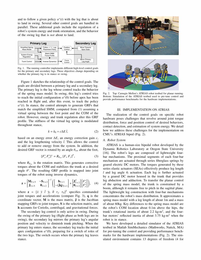
and to follow a given policy α∗(t) with the leg that is aboutto land in swing. Several other control goals are handled inparallel. These additional goals include the regulation of arobot’s system energy and trunk orientation, and the behaviorof the swing leg that is not about to land.
Primary LegSimplified Spring
Mass ModelFollow Leg Placement Policy
Inverse DynamicsTrunk Control
System Energy Regulation
Force Control
Position Control
Match SMM Force Profile
↵⇤(t)
Secondary LegMove Towards
Apex State
Mirror Primary Leg Angle
Fig. 1. The running controller implements different high-level control goalsfor the primary and secondary legs. These objectives change depending onwhether the primary leg is in stance or swing.
Figure 1 sketches the relationship of the control goals. Thegoals are divided between a primary leg and a secondary leg.The primary leg is the leg whose control tracks the behaviorof the spring mass model. In swing, this leg’s control triesto reach the initial configuration α∗(0) before apex has beenreached in flight and, after this event, to track the policyα∗(t). In stance, the control attempts to generate GRFs thatmatch the simplified SMM, computed from (1) assuming avirtual spring between the foot point and the COM of therobot. However, energy and trunk regulation alter this GRFprofile. The stiffness of the virtual leg spring is modulatedthroughout stance,
k = k0 + c∆E l, (2)
based on an energy error ∆E, an energy correction gain c,and the leg lengthening velocity l. This allows the controlto add or remove energy from the system. In addition, thedesired GRF vector is rotated by an angle θrot about the foot,
[F∗x F∗y ]ᵀ = Rθrot [Fx Fy]T , (3)
where Rθrot is the rotation matrix. This generates correctivetorques about the COM and stabilizes the trunk at a desiredangle θ∗. The resulting GRF profile is mapped into jointtorques of the robot using inverse dynamics,
z =
[M5× 5 −S5× 2J2× 5 02× 2
]−1 ( [h5× 1
−(Jq)2× 1
]+
[JT
5× 202× 2
] [F∗xF∗y
] ), (4)
where z = [x y l γl θ τ f τb]T specifies commandedjoint torques and accelerations (compare Fig. 3), q is thecoordinate vector, M is the mass matrix, J is the Jacobianmapping GRFs to joint torques, S is the selection matrix, andh accounts for Coriolis, centrifugal, and gravitational forces.
The secondary leg control is only active in swing. Duringthe swing of the primary leg (flight phase as both legs are inswing), the secondary leg mirrors the primary leg’s angularposition and velocity to diminish trunk pitching. When theprimary leg enters stance, the secondary leg tracks the initialapex configuration α∗(0), preparing for a switch of roles ofthe two legs. The switch occurs when the primary leg leavesstance.
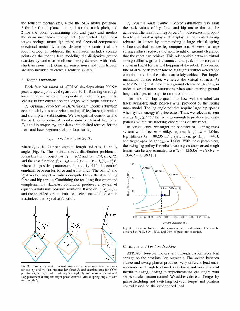
Fig. 2. Top: Carnegie Mellon’s ATRIAS robot testbed for planar running.Bottom: Simulation of the ATRIAS testbed used to pre-tune control andprovide performance benchmarks for the hardware implementations.
III. IMPLEMENTATION ON ATRIASThe realization of the control goals on specific robot
hardware poses challenges that revolve around joint torquedistribution, force and position control of desired behaviors,contact detection, and estimation of system energy. We detailhow we address these challenges for the implementation onCMU’s ATRIAS biped (Fig. 2).
A. Robot System
ATRIAS is a human-size bipedal robot developed by theDynamic Robotics Laboratory at Oregon State University[16]. The robot’s legs are composed of lightweight four-bar mechanisms. The proximal segments of each four-barmechanism are actuated through series fiberglass springs bygeared electric DC motors. The torques generated by theseseries elastic actuators (SEAs) effectively produce leg lengthl and leg angle θl actuation. Each leg is further actuatedby a geared DC motor housed in the trunk that providesleg abduction and adduction. To transfer the planar controlof the spring mass model, the trunk is constrained by aboom, although it remains free to pitch in the sagittal plane.The lightweight leg construction with four-bar mechanismsconcentrates the robot’s mass distribution. It approximates aspring mass model with a leg length of about 1m and a massof about 60kg. Key differences to the spring mass model arethe robot’s COM location about 0.1m above the hips, thetrunk’s rotational inertia of about 2.2 kg·m2, and the four-bar motors’ reflected inertia of about 3.75 kg·m2 when therobot is in stance.
We have developed a detailed simulator of the ATRIAStestbed in Matlab SimMechanics (Mathworks, Natick, MA)for pre-tuning the control and providing performance bench-marks for the hardware implementations (Fig. 2). The sim-ulated environment contains 13 degrees of freedom (4 for
the four-bar mechanisms, 4 for the SEA motor positions,2 for the frontal plane motors, 1 for the trunk pitch, and2 for the boom constraining roll and yaw) and modelsthe main mechanical components (segmented chain, gearstages, springs, motor dynamics) and electrical components(electrical motor dynamics, discrete time control) of therobot testbed. In addition, the simulation includes contactpoints on the robot’s feet, modeling the dissipative groundreaction dynamics as nonlinear spring-dampers with stick-slip transitions [17]. Gaussian sensor noise and joint frictionare also included to create a realistic system.
B. Torque Limitations
Each four-bar motor of ATRIAS develops about 300Nmpeak torque at joint level (gear ratio 50:1). Running on roughterrain forces the robot to operate at motor torque limits,leading to implementation challenges with torque saturation.
1) Optimal Force-Torque Distributions: Torque saturationoccurs mainly in stance when trading off leg force generationand trunk pitch stabilization. We use optimal control to findthe best compromise. A combination of desired leg force,Fl, and hip torque, τH , translates into desired torques for thefront and back segments of the four-bar leg,
τ f /b = τH/2 ± Flls sin (ρ/2) ,
where ls is the four-bar segment length and ρ is the splayangle (Fig. 3). The optimal torque distribution problem isformulated with objectives x1 = τH/2 and x2 = Flls sin (ρ/2)and the cost function f (x1, x2) = −λ1(x1− x∗1)2−λ2(x2− x∗2)2,where the positive parameters λ1 and λ2 shift the controlemphasis between leg force and trunk pitch. The pair x∗1 andx∗2 describes objective values computed from the desired legforce and hip torque. Combining the resulting first-order andcomplementary slackness conditions produces a system ofequations with nine possible solutions. Based on x∗1, x
∗2, λ1, λ2
and the specified torque limits, we select the solution whichmaximizes the objective function.
Fig. 3. Inverse dynamics control during stance computes front and backtorques τ f and τb that produce leg force Fl and accelerations for COMposition (x, y), leg length l, primary leg angle γl, and torso acceleration θ.Leg placement during the flight phase controls virtual spring angle α withrest length l0.
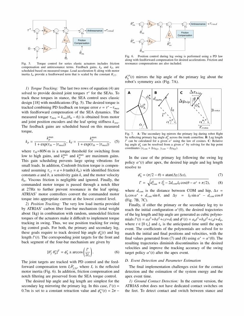
2) Feasible SMM Control: Motor saturations also limitthe peak values of leg force and hip torque that can beachieved. The maximum leg force, Fmax, decreases in propor-tion to the four-bar splay ρ. The splay can be limited duringrebound in stance by commanding a large virtual springstiffness k0 that reduces leg compression. However, a largespring stiffness reduces the apex height or ground clearancethat the robot can achieve. This relationship between virtualspring stiffness, ground clearance, and peak motor torque isshown in Fig. 4 for vertical hopping of the robot. The contourline at 80% peak motor torque highlights stiffness-clearancecombinations that the robot can safely achieve. For imple-mentation on the robot, we select the virtual stiffness (k0= 8820N·m−1) that maximizes ground clearance (4.7cm), inorder to avoid motor saturations when encountering groundheight changes in rough terrain locomotion.
The maximum hip torque limits how well the robot cantrack swing-leg angle policies α∗(t) provided by the springmass model. The leg angle policies require large hip speedswhen system energy Esys decreases. Thus, we select a systemenergy Esys ≥ 445J that is large enough to produce leg anglepolicies within the tracking capabilities of the robot.
In consequence, we target the behavior of a spring masssystem with mass m = 60kg, leg rest length l0 = 1.04m,leg stiffness k0 = 8820N·m−1, system energy Esys = 445J,and target apex height ydes = 1.06m. With these parameters,the swing leg policy for robust running on unobserved roughterrain can be approximated to α∗(t) = 12.835t3 − 2.9736t2 +
1.9343t + 1.1389 [9].
Fig. 4. Contour lines for stiffness-clearance combinations that can beachieved at 75%, 80%, 85%, and 90% of peak motor torque.
C. Torque and Position Tracking
ATRIAS’ four-bar motors act through carbon fiber leafsprings on the proximal leg segments. The switch betweenstance and swing phases produces very different load envi-ronments, with high load inertia in stance and very low loadinertia in swing, leading to implementation challenges withseries elastic actuator control. We address these challenges bygain-scheduling and switching between torque and positioncontrol based on the experienced load.
Antiresonance
Friction Compensation
⌧cmdkp
kd
✓m
+ ++ +
+
++
+ -
+ -
Kff
Im
✓l
0
⌧
⌧⇤
⌧
Fig. 5. Torque control for series elastic actuators includes frictioncompensation and antiresonance terms. Feedback gains, kp and kd , arescheduled based on measured torque. Load acceleration θl along with motorinertia Im provide a feedforward term that is scaled by the constant K f f .
1) Torque Tracking: The last two rows of equation (4) aresolved to provide desired joint torques τ∗ for the SEAs. Totrack these torques in stance, the SEA control uses classicdesign [18] with modifications (Fig. 5). The desired torque istracked combining PD feedback on torque error e = τ∗−τmea
with feedforward compensation of the SEA dynamics. Themeasured torque τmea = ksea(θm − θl) is obtained from motorand joint position encoders and the leaf spring stiffness ksea.The feedback gains are scheduled based on this measuredtorque,
kp =kmax
p
1 + exp(τth − |τmea|), kd =
kmaxd
1 + exp(τth − |τmea|), (5)
where τth=80N·m is a torque threshold for switching fromlow to high gains, and kmax
p and kmaxd are maximum gains.
This gain scheduling prevents large spring vibrations forsmall loads. In addition, Coulomb friction torque is compen-sated assuming τc f = a + b tanh(k θm) with identified frictionconstants a and b, a sensitivity gain k, and the motor velocityθm. Viscous friction is negligible and ignored. Finally, thecommanded motor torque is passed through a notch filterat 27Hz to further prevent resonance in the leaf spring.ATRIAS’ motor controllers convert the commanded motortorque into appropriate current at the lowest control level.
2) Position Tracking: The very low load inertia providedby ATRIAS’ carbon fiber four-bar mechanism (total weightabout 1kg) in combination with random, unmodeled frictiontorques of the actuators make it difficult to implement torquetracking in swing. Thus, we use position tracking for swingleg control goals. For both, the primary and secondary leg,these goals require to track desired hip angle φ∗h(t) and leglength l∗(t). The corresponding joint targets for the front andback segment of the four-bar mechanism are given by
[θ∗f θ∗b]T = φ∗h ± arccos
(l∗
2ls
). (6)
The joint targets are tracked with PD control and the feed-forward compensation term Ir θ
∗f /b, where Ir is the reflected
motor inertia (Fig. 6). In addition, friction compensation andnotch filtering are preserved from the SEA torque control.
The desired hip angle and leg length are simplest for thesecondary leg mirroring the primary leg. In this case, l∗(t) =
0.7m is set to a constant retraction value and φ∗sh (t) = 2π −
Antiresonance
Friction Compensation
+ -
-
+
+
++
+ + +kp
kd
Ir
✓⇤m
✓⇤m ✓⇤m
⌧cmd
✓m
✓m
Fig. 6. Position control during leg swing is performed using a PD lawalong with feedforward compensation for desired accelerations. Friction andresonance compensations are also included.
φ∗ph (t) mirrors the hip angle of the primary leg about the
robot’s symmetry axis (Fig. 7A).
Fig. 7. A: The secondary leg mirrors the primary leg during robot flightby reflecting primary leg angle φp
h across the trunk centerline. B: Leg lengthl∗ can be calculated for a given α∗ using the law of cosines. C: Relativeleg angle φ∗h can be resolved from a given α∗ by solving for the hip pointcoordinates (xcom + ∆xhip, ycom − ∆yhip).
In the case of the primary leg following the swing legpolicy α∗(t) after apex, the desired hip angle and leg lengthresolve to
φ∗h = (π/2 − θ) + atan(∆y/∆x), (7)
l∗ =
√d2
com + l20 − 2dcoml0 cos(θ − α∗ + π/2), (8)
where dcom is the distance between COM and hip, ∆x =
l0 cosα∗ + dcom sin θ, and ∆y = l0 sinα∗ − dcom cos θ(Fig. 7B, 7C).
Finally, if either the primary or the secondary leg try toreach the initial configuration α∗(0), the desired trajectoriesof the leg length and hip angle are generated as cubic polyno-mials l∗(t) = alt3+blt2+clt+dl and φ∗(t) = aφt3+bφt2+cφt+dφ,where t ∈ [0 ta] and ta is the anticipated time until the apexevent. The coefficients of the polynomials are solved for tomatch the initial and final positions and velocities, with thefinal values generated from (7) and (8) using α∗ = α∗(0). Theresulting trajectories diminish discontinuities in the desiredvelocities and improve the tracking accuracy of the swingtarget policy α∗(t) after the apex event.
D. Event Detection and Parameter Estimation
The final implementation challenges exist for the contactdetection and the estimation of the system energy and theapex event time.
1) Ground Contact Detection: In the current version, theATRIAS robot does not have dedicated contact switches onthe feet. To detect contact and switch between stance and
swing control, we rely on a low-pass filtered estimate of thevertical ground reaction force, GRFy = Fl cos(φh + θ), withthe leg force measured from the spring deflections of theSEAs, Fl = (τ f
mea − τbmea)/(2ls sin(ρ/2)).
Based on this estimate, reliable switches between stanceand swing are ensured with a state machine detecting keyevents (Fig. 8). When GRFy exceeds a touch-down thresholdFth1 (20% body weight), the leg switches from swing tostance control. To prevent foot scuffing from triggering falsecontact events, the leg remains locked in stance control onlyif a second threshold Fth2 (50% body weight) is passed. Toexit this stance, the leg has to compress and rebound, duringwhich a drop of GRFy below the 50% threshold triggerstake-off.
Stance
Touch Down
Locked Contact
Rebound
Take Off
SwingGRFy > Fth1
GRFy < Fth1
GRFy < Fth2
GRFy > Fth2
lt � 0 lt�1 < 0
wait(tw)
and
Fig. 8. Reliable switches between stance and swing control states.
2) System Energy: A swing leg policy α∗(t) for robustlocomotion is valid for a particular system energy Esys ofthe spring mass model in flight. This energy is tracked forATRIAS in stance by adapting the virtual leg stiffness (2)based on the energy error ∆E = Esys −E. E is the equivalentspring-mass energy E = 1
2 m(x2 + y2)+mgy of the robot in thepreceding flight phase, where m is the total robot mass, g isthe gravitational acceleration, x and y are the horizontal andvertical velocity of the center of mass at take off, and y is thetake off height. The values of x, y and y are estimated fromthe robot kinematics at the take off event in stance (Fig. 8)using 100ms moving average filters.
3) Time of Apex: The swing leg policy α∗(t) is triggeredat apex. Like system energy, we estimate the time of the apexusing the take off event. From this event, the time it takes toreach apex is estimated as ∆t = y/g.
IV. RESULTS AND DISCUSSION
The implementation of robust running control based on thetheory of the spring mass model introduced a third controllayer to deal with the specific ATRIAS robot platform andits limitations (1st: spring mass model [9], [14]; 2nd: controlmapping to articulated biped [15]; both reviewed in sectionII). To provide a benchmark for what this physical platformshould be capable of with this layered control, we firstpresent results on level and rough terrain running for the highfidelity ATRIAS simulation, and then discuss our preliminaryresults on the actual hardware.
A. Simulation Benchmark Results
The current motor torque saturation of 300N·m limitsATRIAS’s performance. Over flat ground, the simulatedrobot can maintain a constant target apex height with a meanand standard deviation error of 1.061 ± 0.005m at a runningspeed of 2.091 ± 0.017m·s−1 (Fig. 9). The same controllertolerates small terrain height variations up to ±4% of leglength (not shown in Fig. 9).
0.8
0.9
1
1.1
1.2
Ap
ex H
eig
ht (
m)
0 1 2 3 4 5 6 7 8 9 101.5
1.7
1.9
2.1
2.3
2.5
Tim e (s)Sp
ee
d (m
/s)
0.8
0.9
1
1.1
1.2
Ap
ex H
eig
ht (
m)
0 1 2 3 4 5 6 7 8 9 101.5
1.7
1.9
2.1
2.3
2.5
Tim e (s)
Spe
ed
(m/s
)Fig. 9. The simulated system demonstrates steady state running over levelground with constant apex height and forward velocity.
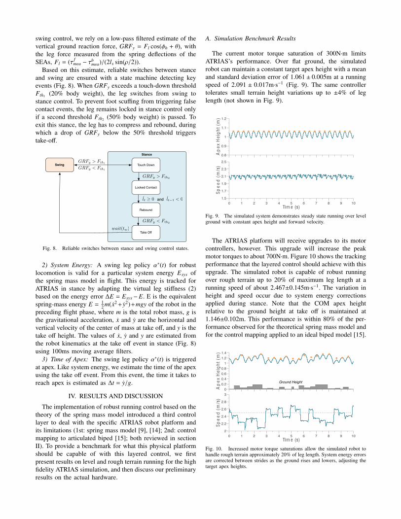
The ATRIAS platform will receive upgrades to its motorcontrollers, however. This upgrade will increase the peakmotor torques to about 700N·m. Figure 10 shows the trackingperformance that the layered control should achieve with thisupgrade. The simulated robot is capable of robust runningover rough terrain up to 20% of maximum leg length at arunning speed of about 2.467±0.145m·s−1. The variation inheight and speed occur due to system energy correctionsapplied during stance. Note that the COM apex heightrelative to the ground height at take off is maintained at1.146±0.102m. This performance is within 80% of the per-formance observed for the theoretical spring mass model andfor the control mapping applied to an ideal biped model [15].
00.20.40.60.81
1.21.4
Ap
ex H
eig
ht (
m)
Ground Height
0 1 2 3 4 5 6 7 8 9 102
2.2
2.4
2.6
2.8
3
Tim e (s)
Spe
ed
(m/s
)
00.20.40.60.81
1.21.4
Ap
ex H
eig
ht (
m)
Ground Height
0 1 2 3 4 5 6 7 8 9 102
2.2
2.4
2.6
2.8
3
Tim e (s)
Spe
ed
(m/s
)
Fig. 10. Increased motor torque saturations allow the simulated robot tohandle rough terrain approximately 20% of leg length. System energy errorsare corrected between strides as the ground rises and lowers, adjusting thetarget apex heights.
B. ATRIAS Hardware Experiments
The transfer of the controller to the robot hardware is anongoing process, which we approach in incremental steps.At the current stage, the embedded control includes thevirtual spring leg behavior in stance with trunk and energyregulation, swing leg mirroring, and the contact detection(section III). The swing leg placement policy α(t)∗ is not yetimplemented. Instead, we use a basic leg placement strategyfor evaluation purposes.
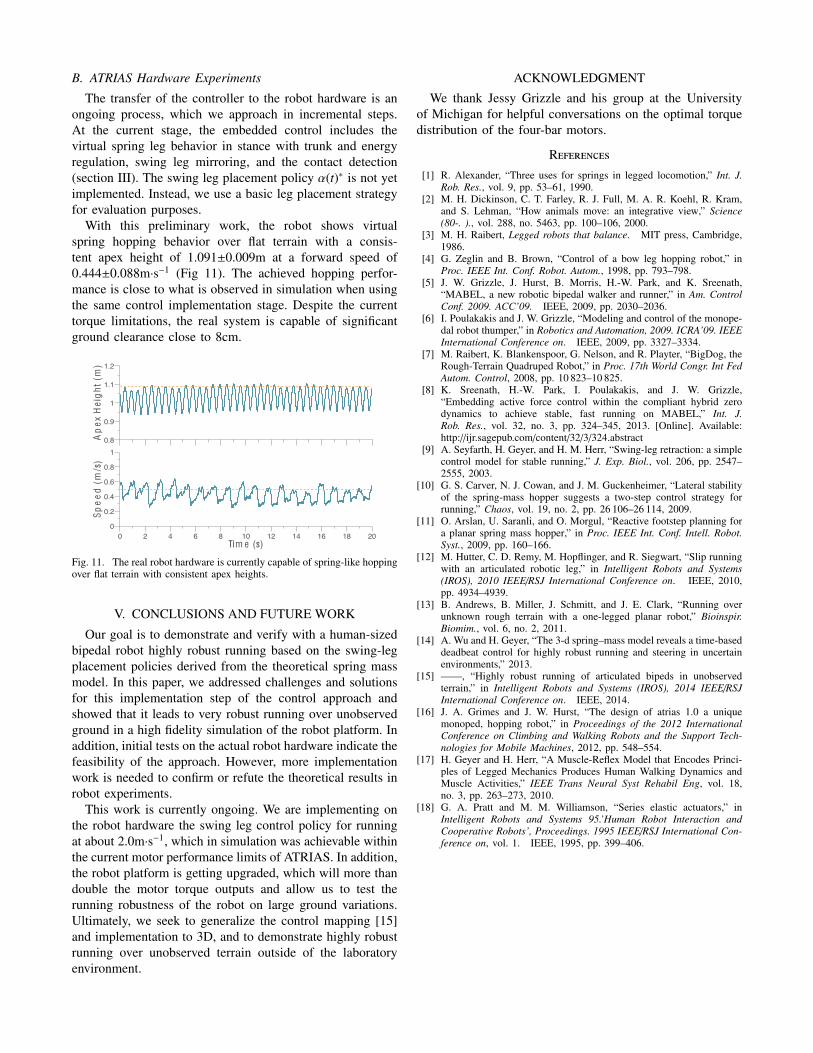
With this preliminary work, the robot shows virtualspring hopping behavior over flat terrain with a consis-tent apex height of 1.091±0.009m at a forward speed of0.444±0.088m·s−1 (Fig 11). The achieved hopping perfor-mance is close to what is observed in simulation when usingthe same control implementation stage. Despite the currenttorque limitations, the real system is capable of significantground clearance close to 8cm.
0.8
0.9
1
1.1
1.2
Ap
ex H
eig
ht (
m)
0 2 4 6 8 10 12 14 16 18 200
0.2
0.4
0.6
0.8
1
Tim e (s)
Spe
ed
(m/s
)
0.6
0.8
1
1.2
1.4
Ap
ex H
eig
ht (
m)
0 2 4 6 8 10 12 14 16 18 200
0.2
0.4
0.6
0.8
1
Tim e (s)
Spe
ed
(m/s
)
Fig. 11. The real robot hardware is currently capable of spring-like hoppingover flat terrain with consistent apex heights.
V. CONCLUSIONS AND FUTURE WORK
Our goal is to demonstrate and verify with a human-sizedbipedal robot highly robust running based on the swing-legplacement policies derived from the theoretical spring massmodel. In this paper, we addressed challenges and solutionsfor this implementation step of the control approach andshowed that it leads to very robust running over unobservedground in a high fidelity simulation of the robot platform. Inaddition, initial tests on the actual robot hardware indicate thefeasibility of the approach. However, more implementationwork is needed to confirm or refute the theoretical results inrobot experiments.
This work is currently ongoing. We are implementing onthe robot hardware the swing leg control policy for runningat about 2.0m·s−1, which in simulation was achievable withinthe current motor performance limits of ATRIAS. In addition,the robot platform is getting upgraded, which will more thandouble the motor torque outputs and allow us to test therunning robustness of the robot on large ground variations.Ultimately, we seek to generalize the control mapping [15]and implementation to 3D, and to demonstrate highly robustrunning over unobserved terrain outside of the laboratoryenvironment.
ACKNOWLEDGMENT
We thank Jessy Grizzle and his group at the Universityof Michigan for helpful conversations on the optimal torquedistribution of the four-bar motors.
References[1] R. Alexander, “Three uses for springs in legged locomotion,” Int. J.
Rob. Res., vol. 9, pp. 53–61, 1990.[2] M. H. Dickinson, C. T. Farley, R. J. Full, M. A. R. Koehl, R. Kram,
and S. Lehman, “How animals move: an integrative view,” Science(80-. )., vol. 288, no. 5463, pp. 100–106, 2000.
[3] M. H. Raibert, Legged robots that balance. MIT press, Cambridge,1986.
[4] G. Zeglin and B. Brown, “Control of a bow leg hopping robot,” inProc. IEEE Int. Conf. Robot. Autom., 1998, pp. 793–798.
[5] J. W. Grizzle, J. Hurst, B. Morris, H.-W. Park, and K. Sreenath,“MABEL, a new robotic bipedal walker and runner,” in Am. ControlConf. 2009. ACC’09. IEEE, 2009, pp. 2030–2036.
[6] I. Poulakakis and J. W. Grizzle, “Modeling and control of the monope-dal robot thumper,” in Robotics and Automation, 2009. ICRA’09. IEEEInternational Conference on. IEEE, 2009, pp. 3327–3334.
[7] M. Raibert, K. Blankenspoor, G. Nelson, and R. Playter, “BigDog, theRough-Terrain Quadruped Robot,” in Proc. 17th World Congr. Int FedAutom. Control, 2008, pp. 10 823–10 825.
[8] K. Sreenath, H.-W. Park, I. Poulakakis, and J. W. Grizzle,“Embedding active force control within the compliant hybrid zerodynamics to achieve stable, fast running on MABEL,” Int. J.Rob. Res., vol. 32, no. 3, pp. 324–345, 2013. [Online]. Available:http://ijr.sagepub.com/content/32/3/324.abstract
[9] A. Seyfarth, H. Geyer, and H. M. Herr, “Swing-leg retraction: a simplecontrol model for stable running,” J. Exp. Biol., vol. 206, pp. 2547–2555, 2003.
[10] G. S. Carver, N. J. Cowan, and J. M. Guckenheimer, “Lateral stabilityof the spring-mass hopper suggests a two-step control strategy forrunning,” Chaos, vol. 19, no. 2, pp. 26 106–26 114, 2009.
[11] O. Arslan, U. Saranli, and O. Morgul, “Reactive footstep planning fora planar spring mass hopper,” in Proc. IEEE Int. Conf. Intell. Robot.Syst., 2009, pp. 160–166.
[12] M. Hutter, C. D. Remy, M. Hopflinger, and R. Siegwart, “Slip runningwith an articulated robotic leg,” in Intelligent Robots and Systems(IROS), 2010 IEEE/RSJ International Conference on. IEEE, 2010,pp. 4934–4939.
[13] B. Andrews, B. Miller, J. Schmitt, and J. E. Clark, “Running overunknown rough terrain with a one-legged planar robot,” Bioinspir.Biomim., vol. 6, no. 2, 2011.
[14] A. Wu and H. Geyer, “The 3-d spring–mass model reveals a time-baseddeadbeat control for highly robust running and steering in uncertainenvironments,” 2013.
[15] ——, “Highly robust running of articulated bipeds in unobservedterrain,” in Intelligent Robots and Systems (IROS), 2014 IEEE/RSJInternational Conference on. IEEE, 2014.
[16] J. A. Grimes and J. W. Hurst, “The design of atrias 1.0 a uniquemonoped, hopping robot,” in Proceedings of the 2012 InternationalConference on Climbing and Walking Robots and the Support Tech-nologies for Mobile Machines, 2012, pp. 548–554.
[17] H. Geyer and H. Herr, “A Muscle-Reflex Model that Encodes Princi-ples of Legged Mechanics Produces Human Walking Dynamics andMuscle Activities,” IEEE Trans Neural Syst Rehabil Eng, vol. 18,no. 3, pp. 263–273, 2010.
[18] G. A. Pratt and M. M. Williamson, “Series elastic actuators,” inIntelligent Robots and Systems 95.’Human Robot Interaction andCooperative Robots’, Proceedings. 1995 IEEE/RSJ International Con-ference on, vol. 1. IEEE, 1995, pp. 399–406.