Robust Quasistatic Finite Elements and Flesh Simulationjteran/papers/TSIF05.pdfRobust Quasistatic...
11
Eurographics/ACM SIGGRAPH Symposium on Computer Animation (2005) K. Anjyo, P. Faloutsos (Editors) Robust Quasistatic Finite Elements and Flesh Simulation Joseph Teran † Eftychios Sifakis ‡ Geoffrey Irving ‡ Ronald Fedkiw ‡ Stanford University Stanford University Stanford University Stanford University Intel Corporation Pixar Animation Studios Industrial Light+Magic Abstract Quasistatic and implicit time integration schemes are typically employed to alleviate the stringent time step re- strictions imposed by their explicit counterparts. However, both quasistatic and implicit methods are subject to hidden time step restrictions associated with both the prevention of element inversion and the effects of discon- tinuous contact forces. Furthermore, although fast iterative solvers typically require a symmetric positive definite global stiffness matrix, a number of factors can lead to indefiniteness such as large jumps in boundary conditions, heavy compression, etc. We present a novel quasistatic algorithm that alleviates geometric and material indefi- niteness allowing one to use fast conjugate gradient solvers during Newton-Raphson iteration. Additionally, we robustly compute smooth elastic forces in the presence of highly deformed, inverted elements alleviating artificial time step restrictions typically required to prevent such states. Finally, we propose a novel strategy for treating both collision and self-collision in this context. Categories and Subject Descriptors (according to ACM CCS): I.3.5 [Computer Graphics]: Computational Geometry and Object Modeling – Physically based modeling; I.3.7 [Computer Graphics]: Three-Dimensional Graphics and Realism – Animation 1. Introduction Fast and robust simulations of elastic solids are becoming in- creasingly important in computer graphics applications due largely to the prominence of virtual characters. Feature films such as Van Helsing, Spiderman, The Lord of the Rings and countless others benefit from the use of humanoid characters in scenes that would be difficult and expensive if not impos- sible to create with live actors, see e.g. [KMGB04, ST04]. Typical models are composed of an underlying skeleton whose motion is prescribed kinematically (from motion cap- ture or traditional animation) and a mechanism for transmit- ting the skeletal motion to skin deformation. Physics based simulations of musculature and fleshy tissues are becoming increasingly popular for producing these deformations, es- pecially when virtual characters undergo contact and colli- sion with the surrounding environment. Moreover, faithfully depicting the artist’s conception of the character requires reasonably high resolution tetrahedral meshes placing addi- tional demands for efficiency on the simulation algorithm. Since explicit time integration schemes can often have strin- gent time step restrictions, various authors have investigated † email: [email protected] ‡ email: {sifakis|irving|fedkiw}@cs.stanford.edu the use of semi-implicit (e.g. [BMF03]), fully implicit (e.g. [TF88b, BW98]) and quasistatic (e.g. [HFS * 01, MMDJ01]) time integration schemes. Quasistatic schemes ignore iner- tial effects and thus are not suitable for simulating less con- strained phenomena such as ballistic motion. However, in applications where inertial effects are relatively small com- pared to the deformation caused by contact, collision, and time varying boundary conditions, quasistatic solvers can of- ten provide a speedup of one to two orders of magnitude over explicit schemes. For example, quasistatic simulations are well suited for flesh deformation where the flesh is rigidly attached to bones and heavily influenced by contact, colli- sion and self-collision. Although implicit and quasistatic schemes remove the time step restriction associated with wave propagation, the Newton-Raphson method used to solve the resulting nonlin- ear equations may produce inverted elements during itera- tion when large time steps are used, bringing the algorithm to a halt. For example, large displacement boundary condi- tions tend to invert elements unless steps are taken to dis- tribute the effects to surrounding elements, and the typical approach is to impose an artificial time step restriction even in the quasistatic case. This has been discussed in both the computer graphics (e.g. [HFS * 01]) and the computational physics (e.g. [GW03]) literature. Even in the case where the c The Eurographics Association 2005.
Transcript of Robust Quasistatic Finite Elements and Flesh Simulationjteran/papers/TSIF05.pdfRobust Quasistatic...
Eurographics/ACM SIGGRAPH Symposium on Computer Animation (2005)K. Anjyo, P. Faloutsos (Editors)
Robust Quasistatic Finite Elements and Flesh Simulation
Joseph Teran† Eftychios Sifakis‡ Geoffrey Irving‡ Ronald Fedkiw‡
Stanford University Stanford University Stanford University Stanford UniversityIntel Corporation Pixar Animation Studios Industrial Light+Magic
Abstract
Quasistatic and implicit time integration schemes are typically employed to alleviate the stringent time step re-strictions imposed by their explicit counterparts. However, both quasistatic and implicit methods are subject tohidden time step restrictions associated with both the prevention of element inversion and the effects of discon-tinuous contact forces. Furthermore, although fast iterative solvers typically require a symmetric positive definiteglobal stiffness matrix, a number of factors can lead to indefiniteness such as large jumps in boundary conditions,heavy compression, etc. We present a novel quasistatic algorithm that alleviates geometric and material indefi-niteness allowing one to use fast conjugate gradient solvers during Newton-Raphson iteration. Additionally, werobustly compute smooth elastic forces in the presence of highly deformed, inverted elements alleviating artificialtime step restrictions typically required to prevent such states. Finally, we propose a novel strategy for treatingboth collision and self-collision in this context.
Categories and Subject Descriptors(according to ACM CCS): I.3.5 [Computer Graphics]: Computational Geometryand Object Modeling – Physically based modeling; I.3.7 [Computer Graphics]: Three-Dimensional Graphics andRealism – Animation
1. Introduction
Fast and robust simulations of elastic solids are becoming in-creasingly important in computer graphics applications duelargely to the prominence of virtual characters. Feature filmssuch as Van Helsing, Spiderman, The Lord of the Rings andcountless others benefit from the use of humanoid charactersin scenes that would be difficult and expensive if not impos-sible to create with live actors, see e.g. [KMGB04, ST04].Typical models are composed of an underlying skeletonwhose motion is prescribed kinematically (from motion cap-ture or traditional animation) and a mechanism for transmit-ting the skeletal motion to skin deformation. Physics basedsimulations of musculature and fleshy tissues are becomingincreasingly popular for producing these deformations, es-pecially when virtual characters undergo contact and colli-sion with the surrounding environment. Moreover, faithfullydepicting the artist’s conception of the character requiresreasonably high resolution tetrahedral meshes placing addi-tional demands for efficiency on the simulation algorithm.
Since explicit time integration schemes can often have strin-gent time step restrictions, various authors have investigated
† email: [email protected]‡ email: {sifakis|irving|fedkiw}@cs.stanford.edu
the use of semi-implicit (e.g. [BMF03]), fully implicit (e.g.[TF88b, BW98]) and quasistatic (e.g. [HFS∗01, MMDJ01])time integration schemes. Quasistatic schemes ignore iner-tial effects and thus are not suitable for simulating less con-strained phenomena such as ballistic motion. However, inapplications where inertial effects are relatively small com-pared to the deformation caused by contact, collision, andtime varying boundary conditions, quasistatic solvers can of-ten provide a speedup of one to two orders of magnitude overexplicit schemes. For example, quasistatic simulations arewell suited for flesh deformation where the flesh is rigidlyattached to bones and heavily influenced by contact, colli-sion and self-collision.
Although implicit and quasistatic schemes remove thetime step restriction associated with wave propagation, theNewton-Raphson method used to solve the resulting nonlin-ear equations may produce inverted elements during itera-tion when large time steps are used, bringing the algorithmto a halt. For example, large displacement boundary condi-tions tend to invert elements unless steps are taken to dis-tribute the effects to surrounding elements, and the typicalapproach is to impose an artificial time step restriction evenin the quasistatic case. This has been discussed in both thecomputer graphics (e.g. [HFS∗01]) and the computationalphysics (e.g. [GW03]) literature. Even in the case where the
c© The Eurographics Association 2005.
Teran et al. / Robust Quasistatic Finite Elements and Flesh Simulation
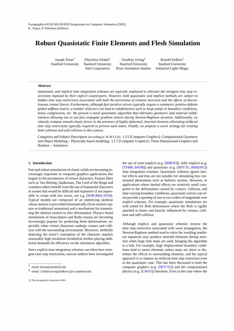
Figure 1: The particles of a tetrahedron mesh are randomlyscattered across a tenfold magnification of its bounding boxand the object is subsequently evolved to steady state usingour robust quasistatic solver. From top to bottom and left toright the Newton iteration counts are 0, 1, 2, 10, 40, and 80.The hands and feet are specified as boundary conditions.
final mesh will be inversion free, artificially small time stepsare required to ensure that every intermediate state consid-ered during Newton-Raphson iteration is also inversion freerestricting the speed at which one can converge to the de-sired solution. Recently, researchers have aimed at handlinginversion using altitude springs [MBTF03], volume preser-vation terms [THMG04], rotated linear models [MG04], etc.However, these methods change or limit the underlying par-tial differential equation, whereas [ITF04] allows for generalnonlinear constitutive models with forces that are smoothenough to be used in conjunction with iterative methods.Thus, we adopt the approach of [ITF04] and extend it to thequasistatic regime removing the artificial time step restric-tion required by other schemes making our solution methodextremely efficient.
In each Newton-Raphson iteration, the nonlinear system ofequations is reduced to a linear system that must be solvedto advance to the next iteration. This linear system is guar-anteed to be symmetric and positive definite in the vicin-ity of equilibrium states, enabling the use of fast conjugategradient solvers. Unfortunately, the use of large time stepsproduces substantial divergence from a steady state, lead-ing to a symmetric linear system that is often indefinite.State of the art finite element packages such as NIKE3D stilluse direct solvers such as that proposed in [TWS80], eventhough such methods are much slower and require consid-erably more memory than iterative methods. [GW03] first
try a fast iterative solver switching to a slower direct methodwhen it fails. [HFS∗01] discussed these issues in the contextof quasistatic simulation pointing out the erratic behavior ofconjugate gradient methods and a preference against directmethods. By adding an artificial “viscosity” to their simu-lations, they were able to obtain reasonable results with aGMRES iterative scheme. In the context of implicit time in-tegration, [CK02] pointed out that extra damping forces suchas those applied in [BW98,VT00] can help to overcome in-definiteness, but not guarantee it. Furthermore, they pointout that this damping degrades the realism of the simulation.Instead, they take a closer look at the problem in the caseof springs identifying compression as a source of indefinite-ness and proposing a technique to guarantee definiteness inthe special case of cloth simulation with springs. A key con-tribution of our paper is a new and general method for guar-anteeing positive definiteness, thus allowing for the use offast conjugate gradient solvers under all circumstances (in-cluding inversion) for arbitrary constitutive models in thefinite element framework. Our method modifies the searchpath followed towards equilibrium without altering the setof equilibrium solutions or the governing equations.
2. Previous Work
[TPBF87, TF88b, TF88a] pioneered deformable modelsin computer graphics including early work on plasticityand fracture. Finite element simulations have been usedto model a hand grasping a ball [GMTT89], for vir-tual surgery [PDA01], fracture [OH99, MMDJ01, OBH02,MBF04], etc. Other work includes the adaptive frameworksof [DDCB01, GKS02, CGC∗02b], the rotation based ap-proaches in [MDM∗02, MG04, CK05] (see also [TW88]),the bending models in [BMF03,GHDS03], the precomputeddata driven models of [JF03], and the point based methodsin [MKN∗04].
The construction of muscles and/or flesh deformation is im-portant for computer graphics characters, and anatomy basedmodeling techniques of varying resolutions have been ap-plied. [WV97,SPCM97] used anatomically based models ofmuscles, tendons and fatty tissue to deform an outer skinlayer. [NTHF02] fit deformable B-spline solids to anatomicdata in order to create volumetric, anisotropic representa-tions of muscles and their internal structures. [AHS03] useda variety of techniques to model a human hand. More biome-chanically accurate techniques for muscle simulation wereproposed in [CZ92,HFS∗01,TBNF03], and a number of re-searchers are working to simulate data from the NIH visiblehuman dataset, e.g. [ZCK98,HFS∗01,DCKY02,TBNF03].
Instead of creating an explicit model for muscle and fattytissue, one can place an articulated skeleton inside the char-acter skin and formulate correspondences between each ver-tex on the skin mesh and the various joints in the skeleton.This is typically called enveloping or skinning and can suf-fer from a number or artifacts especially near joints such as
c© The Eurographics Association 2005.

Teran et al. / Robust Quasistatic Finite Elements and Flesh Simulation
elbows and shoulders. A number of techniques have beenproposed to overcome these difficulties, see for example[LCF00, SRC01, WP02, MG03]. [ACP02] used these tech-niques in conjunction with range scan data, and [KM04]used them to model a human hand. [KJP02] proposed a sim-ilar method that used principal component analysis and a li-brary of deformations precomputed with nonlinear static fi-nite element analysis. Although these techniques are fast anddo not require one to build an underlying muscle model foreach character, they can lead to lower quality results thanfull finite element simulations. A physically based approachwas taken in [JP02] to add ballistic motion to character skinsin otherwise kinematically constructed motions. [CGC∗02a]approaches this problem by embedding the character in acoarse finite element mesh which deforms rigidly with thebones, but obeys a linear finite element model locally to eachbone.
3. Quasistatic Formulation
Using Newton’s second law of motion we can describe theevolution of a deformable body using the equations~xt =~vand~vt = M−1~f(t,~x,~v) where~x,~v and~f denote the positions,velocities and aggregate forces ofall the nodes of the tetra-hedral mesh. (We usex as the vector valued position of asingle node.)M is the mass matrix, which is diagonal in ourlumped mass formulation. The nodal forces can be decom-posed into internal and external forces,~f =~f int +~fext, thelatter being supplied as time varying input to the simulation.
We apply a quasistatic assumption that both the accelerationsand velocities are zero to obtain~f(t,~x,~0) =~0 which statesthat the externally supplied time varying input must be bal-anced by the internal resistance of the material. In particular,we use a nonlinear finite element method to solve for the in-ternal forces, and thus we must invert a nonlinear equationto find the time varying positions~x(t) at any timet. This isaccomplished with a Newton-Raphson iterative solver, andeach step towards the steady state solution begins with thelinearization of the nodal forces about the current solutionestimate~xk, i.e.~f(~xk +∆~xk)≈~f(~xk)+ (∂~f/∂~x)
∣∣∣~xk
∆~xk where
∆~xk =~xk+1 −~xk. Since we desire force equilibrium with~f(~xk+1) =~f(~xk +∆~xk) =~0, we solve the linear system
− ∂~f∂~x
∣∣∣∣∣~xk
∆~xk =~f(~xk) (1)
to find the next iterate~xk+1.
Although the quasistatic assumption does not apply to freefalling, unconstrained, lightly damped objects whose rich-ness of deformation is largely enhanced by the effects of in-ertia, it is a viable modeling strategy for a range of applica-tions in which boundary conditions and external forces pre-dominantly determine the material state (e.g. skeletal mus-cles under a variety of conditions).
4. Strain Energy
For a hyperelastic material, the nodal forces can be definedvia the energy as~f = −∂Ψ/∂~x, and thus we can rewriteequation (1) as
∂ 2Ψ∂~x2
∣∣∣∣~xk
∆~xk = −∂Ψ∂~x
∣∣∣∣~xk
. (2)
That is, the global stiffness matrix−∂~f/∂~x is alwayssym-metric, as a result of the hyperelastic energy having continu-ous second derivatives with respect to the spatial configura-tion. Furthermore, a steady state corresponds to a local min-imum of the hyperelastic energy indicating that the energyHessian,∂ 2Ψ/∂~x2, (or equivalently the global stiffness ma-trix) is positive definite in the vicinity of anisolatedsteadystate. Moreover, systems that possess steady states along acontinuous manifold in configuration space, such as under-constrained bodies with rigid degrees of freedom (e.g. a sin-gle spring with only one fixed endpoint that is otherwise freeto rotate), still exhibit semi-definite stiffness matrices at theirsteady state. Thus, such systems can be reduced to the fullyconstrained case by factoring out the manifold of the config-uration space that does not affect the hyperelastic energy.
Symmetry of the coefficient matrix in the linear system (2)allows for the use of symmetric solvers, and direct meth-ods are commonly used. However, the fact that the stiffnessmatrix is positive definite close to the steady state suggeststhat symmetric positive definite solvers such as the conju-gate gradient methodmight be applicable. This would al-leviate the drawbacks of direct methods including the needto explicitly form the stiffness matrix, the memory demandsincurred by matrix fill during the direct solve, and the exces-sive computational expense of direct solvers as opposed toiterative methods.
Our method modifies the coefficient matrix in equation (2)into a positive definitesymmetric matrix and proceeds tocompute the next iterate∆~xk using this modified system.We emphasize that this modification only alters individualsteps towards a minimum of the strain energy and not thoseminima themselves. These modifications are localized to re-gions of the simulation mesh that contribute to this indefi-niteness. This practice of modifying the Hessian of the opti-mization functional is common in the optimization literature(see e.g. [GMW81]) and is usually referred to as a modifiedNewton method.
5. Finite Element Forces
We follow the notation of [TBNF03], and their geometricinterpretation of the finite element method. Consider a timedependent mapφ from the undeformed material coordinatesX to world coordinatesx. The stress at a pointX in the ma-terial depends on the deformation gradientF(X) = ∂x/∂Xof this mapping. We use constant strain tetrahedral elementswhereF is a constant 3×3 matrix in each tetrahedron. We
c© The Eurographics Association 2005.

Teran et al. / Robust Quasistatic Finite Elements and Flesh Simulation
Figure 2: Illustration of large deformation in conjunctionwith collision. The hands and feet are set as boundary con-ditions for the first row, but only the feet are fixed for themiddle and bottom rows.
define edge vectors for each tetrahedron in both material co-ordinates,dm1 = X1−X0, dm2 = X2−X0, dm3 = X3−X0,and world coordinates,ds1 = x1− x0, ds2 = x2− x0, ds3 =x3− x0, and construct 3×3 matricesDm andDs using theedge vectors as columns. ThenF = DsD−1
m , andD−1m is con-
stant and can be precomputed and stored for efficiency.
For hyperelastic materials, stress is defined as the derivativeof a strain energy typically constructed from various straininvariants, and we use the first Piola-Kirchhoff stress whichis the gradient of the strain energy with respect to the de-formation gradient,P= ∂Ψ/∂F. P maps area weighted nor-mals in material space to forces in world space. The forceon a nodei due to a single tetrahedron incident to it isgi =−P(A1N1 +A2N2 +A3N3)/3, where theA jN j are thearea weighted normals of the faces of the tetrahedron inci-dent to nodei. Since these do not change during the simula-tion, we can precompute a vectorbi such thatgi = Pbi . Forefficiency, we computeg0 =−(g1+g2+g3) and compactlyexpress the other threegi asG = PBm whereG = (g1,g2,g3)andBm = (b1,b2,b3) = −VD−T
m with V the volume of thetetrahedron in material space.
As noted in [ITF04], the first Piola-Kirchhoff stress is in-variant under rotations of either material or world space forisotropic materials. Furthermore, the deformation gradientcan be transformed into a diagonal matrix,F, with an appli-cation of a material and a world space rotation,F = UFVT .This decomposition is obtained from the standard singularvalue decomposition ofF along with the subsequent removal
of any reflections in the orthogonalU andV. This requiresthe negation of the smallest singular value ofF for invertedtetrahedra. Combining the rotational invariance of the firstPiola-Kirchoff stress with the diagonalization of the defor-mation gradient yields
P(F) = UP(UTFV)VT = UP(F)VT (3)
whereP(F) is also diagonal for isotropic materials. This fac-torization is particularly convenient, because it allows for asimple extension of the constitutive model to inverted ele-ments in a smooth manner. That is, one only needs to modifythe diagonalP(F) to be valid for a single negative entry inthe diagonalF. For more details, see [ITF04].
6. Element Stiffness Matrix
The global stiffness matrix in equation (1) is constructedfrom the additive contributions of the element stiffness ma-trices,−∂ f/∂x, which are based on contributions from in-dividual tetrahedra. As a result of this additive decomposi-tion, definiteness of the element stiffness matrices is a suffi-cient condition for definiteness of the global stiffness matrix.Motivated by this fact, we manipulate the element stiffnessmatrix to ensure global definiteness. In section8 we showthat this elemental manipulation amounts to the solution of asingle 3×3 symmetric eigenproblem and a few simple alge-braic operations. In contrast, dealing with the global stiffnessmatrix directly can be prohibitively expensive, especially ifeigenanalysis or Cholesky factorization of that matrix is re-quired, as in most standard approaches to treating locallyindefinite optimization problems [GMW81].
In order to establish the positive definiteness of the elementstiffness matrix, we must ensure thatδxT(−∂ f/∂x)δx =−δxTδ f > 0 for any incrementδx. Using the formulas fromthe last section and some tensor manipulations yields
δxTδ f =
3
∑i=1
δxTi δgi −δxT
0
3
∑i=1
δgi =3
∑i=1
(δxi −δx0)Tδgi
= δDs : δG = tr[δDTs δG] =−Vtr[δDT
s δPD−Tm ]
=−Vtr[D−Tm δDT
s δP] =−Vtr[δFTδP] =−V (δF : δP) .
Since the material element volumeV is always a positiveconstant, the positive definiteness condition reduces toδF :δP > 0 or δF : (∂P/∂F) : δF > 0. Therefore, the positivedefiniteness of the element stiffness matrix is equivalent tothe positive definiteness of the fourth order tensor∂P/∂F.This result is in direct analogy with the energy based formu-lation of the Newton-Raphson iteration system (2), since bydefinitionP = ∂Ψ/∂F and thus∂P/∂F = ∂ 2Ψ/∂F2.
7. Diagonalization
Testing and enforcing positive definiteness of the fourth or-der tensor∂P/∂F directly can be rather unwieldy. Instead,
c© The Eurographics Association 2005.
Teran et al. / Robust Quasistatic Finite Elements and Flesh Simulation
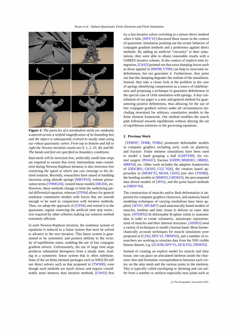
Figure 3: Simulation of quasistatic flesh deformation driven by a kinematic skeleton.
we start as in [ITF04] by rotating both stresses and defor-mations into diagonal space (transforming our configurationusing the rotation matrices that diagonalize the currentF andP). In order to do this, first note thatδP = (∂P(F)/∂F)|F :δF where we explicitly stress the dependency ofP onF withP(F). We can manipulate this equality into
δP =∂UP(UTFV)VT
∂ (UTFV)
∣∣∣∣F
: δ (UTFV)
= U{
∂P(F)∂F
∣∣∣∣UT FV
: UTδFV
}VT
= U{
∂P∂F
∣∣∣∣F
: UTδFV
}VT (4)
where the first equality comes from equation (3) and re-placingδF with a rotated version, the second comes froma change of variables and the fact thatU andV are chosenindependent ofF, and the third comes from choosingU andV to be the rotation matrices that diagonalize the initial valueof F, i.e. where we evaluate∂P/∂F to linearize for iteration.Also in the last equality, we drop the explicit dependence ofP onF.
Equation (4) provides all the information we need for solv-ing the Newton-Raphson iteration system using a conjugategradient solver, since the nodal force differentials can read-ily be computed from the stress differentials asδG = δPBm.Furthermore we have
δP : δF = U{
∂P∂F
∣∣∣∣F
: UTδFV
}VT : δF
= UTδFV :
∂P∂F
∣∣∣∣F
: UTδFV
illustrating that the condition for definiteness,δP : δF > 0,
derived in section6 is equivalent to positive definiteness of(∂P/∂F)|F. We might expect that applying the rotations thatdiagonalize the current deformationF to δP andδF wouldinduce a simple structure for the tensor(∂P/∂F)|F. In factthis tensor turns out to have a block diagonal structure in thecase of isotropic materials.
8. Enforcing Positive Definiteness
In order to reveal the block diagonal structure of(∂P/∂F)|F,we rewrite the 3× 3× 3× 3 fourth order tensor as a9 × 9 matrix. To do this, we consider the rearrange-ment of a 3× 3 matrix S into the 9× 1 vector(s11,s22,s33,s12,s21,s13,s31,s23,s32). We can then represent(∂P/∂F)|F as the 9×9 matrix that maps the vector equiva-lent ofδF to the vector equivalent ofδP. For isotropic mate-rials this matrix is block diagonal with diagonal componentsA, B12, B13 andB23 where
A =
α11+β11+ γ11 γ12 γ13
γ12 α22+β22+ γ22 γ23
γ13 γ23 α33+β33+ γ33
, Bi j =[
αi j βi j
βi j αi j
]Here,
αi j = 2ΨI +4(σ2i +σ
2j )ΨII
βi j = 4σiσ j ΨII −2III ΨIII
σiσ j
γi j =(
2σi 4σ3i
2IIIσi
)∂ 2Ψ
∂ (I , II , III )2
2σ j
4σ3j
2IIIσ j
+4III ΨIII
σiσ j
c© The Eurographics Association 2005.
Teran et al. / Robust Quasistatic Finite Elements and Flesh Simulation
whereΨ = Ψ(I , II , III ) is the strain energy written in termsof the invariantsI = tr C, II = C : C and III = detC withC = FTF and subscripts representing partial derivatives.Also, σ1, σ2 andσ3 are the diagonal components that con-stituteF.
Positive definiteness of(∂P/∂F)|F is equivalent to positivedefiniteness of each of the blocksA, B12, B13 andB23. ForA a simple 3× 3 diagonalization is required, followed bythe clamping of all negative eigenvalues to zero. For the 2×2 matricesB12, B13 andB23 no eigenanalysis is necessarysince the negative eigenvalue, if present, can be clamped tozero analytically.
Our algorithm computes the stress differentialδPas outlinedin equation (4). First we compute the rotated deformationdifferentialUTδFV, and then convert this 3×3 second ordertensor into a 9×1 vector and multiply it by the 9×9 matrixfor (∂P/∂F)|F to carry out the contraction. Of course, weuse the clamped positive definite version of(∂P/∂F)|F. Theresult is then converted from a 9×1 vector back to a 3×3second order tensor, before being premultiplied byU andpostmultiplied byVT .
Since we clamp eigenvalues to zero, the element stiffnessmatrices are only positive semi-definite, not positive defi-nite, which raises the issue of whether the resulting globalstiffness matrix could be semi-definite or ill-conditioned it-self. In practice, the additive contributions of neighboringelements and boundary conditions always lead to a positivedefinite global stiffness matrix, even for configurations asextreme as shown in Figure1. (Note that onecouldclamp toa small positive value as well.) The effect of boundary condi-tions on the definiteness of the stiffness matrix is analogousto that observed in the matrix resulting from the discretiza-tion of the Poisson equation. When all Neumann bound-ary conditions are specified, the resulting matrix is posi-tive semi-definite. In this case a special version of Conju-gate Gradients is still applicable, since an analytic descrip-tion of the null space is available and, similarly, the globalstiffness matrix of an elastic object has a null space corre-sponding to global translation and linearized rotation. Speci-fication of one or more Dirichlet boundary conditions makesthe Poisson matrix strictly positive definite, with positionalconstraints having the same effect on the definiteness of theglobal stiffness matrix for elasticity.
9. Inverted Elements
Typically, realistic constitutive models have infinite strainenergy as the volume of an element approaches zero, and thisdiscourages element inversion when the equations of motionare integrated with a small enough time step to resolve thestiff material response. Nevertheless, each Newton-Raphsoniteration of a quasistatic solver begins with a linearization ofthe elastic forces after which only a finite amount of energyis required to invert the element. In order to efficiently solve
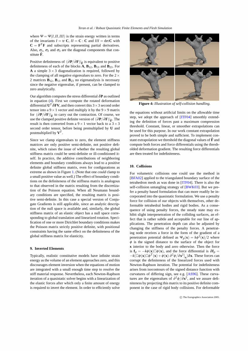
Figure 4: Illustration of self-collision handling.
the equations without artificial limits on the allowable timestep, we adopt the approach of [ITF04] smoothly extend-ing the definition of forces past a maximum compressionthreshold. Constant, linear, or smoother extrapolations canbe used for this purpose. In our work constant extrapolationproved to be both simple and sufficient. To implement con-stant extrapolation we threshold the diagonal values ofF andcompute both forces and force differentials using the thresh-olded deformation gradient. The resulting force differentialsare then treated for indefiniteness.
10. Collisions
For volumetric collisions one could use the method in[BFA02] applied to the triangulated boundary surface of thetetrahedron mesh as was done in [ITF04]. There is also theself-collision untangling strategy of [BWK03]. But we pre-fer a penalty based formulation that can more readily be in-corporated into the quasistatic formulation. We use a penaltyforce for collision of our objects with themselves, other de-formable tetrahedral bodies and rigid bodies. As a conse-quence of using penalty forces, the steady state may ex-hibit slight interpenetration of the colliding surfaces, an ef-fect that is rather subtle and acceptable for our line of ap-plications. The penetration depth can also be adjusted bychanging the stiffness of the penalty forces. A penetrat-ing node receives a force in the form of the gradient of apenetration potential defined asΨp(x) = kφ2(x)/2 whereφ is the signed distance to the surface of the object forx interior to the body and zero otherwise. Then the forceis fp = −kφ(x)∇φ(x), and the force differential isδ fp =−k(∇φ(x)∇φT(x)+ φ(x) ∂ 2φ/∂x2
∣∣x)δx. These forces can
corrupt the definiteness of the linearized forces used withNewton-Raphson iteration. The potential for indefinitenessarises from isocontours of the signed distance function withcurvatures of differing sign, see e.g. [AS96]. These curva-tures are the eigenvalues of∂ 2φ/∂x2, and we assure defi-niteness by projecting this matrix to its positive definite com-ponent in the case of rigid body collisions. For deformable
c© The Eurographics Association 2005.
Teran et al. / Robust Quasistatic Finite Elements and Flesh Simulation
object collisions, we omit the last term altogether. As before,this modification does not change the equilibrium states,only the convergence path towards one of these states.
We take a level set approach (see e.g. [OF02]) to computingpenetration depth as did [FL01,MAC04], but instead of up-dating the level set function as the object deforms we utilizea static level set in material space as in [HFS∗01]. However,many key aspects of our algorithm are significantly differ-ent than that proposed in [HFS∗01]. For each rigid and de-formable object in the scene, we first precompute a signeddistance function on a uniform Cartesian or octree grid asin [GBF03]. This representation is computed in object spacefor rigid bodies and material space for deformable bodiesand is not updated as the simulation progresses. Collectingthe depth, normal and curvature information is straightfor-ward for rigid bodies, but we propose a novel approach fordeformable tetrahedral bodies.
To compute point collisions against deforming tetrahedralbodies, we maintain a bounding box hierarchy for the tetra-hedra in each body. Then for each point, we use this hierar-chy to find any tetrahedra that our candidate point may lieinside (inverted tetrahedra are ignored as they represent neg-ative space). For each tetrahedron, we compute the barycen-tric coordinates of our candidate point to determine if thepoint is either inside or very close to the tetrahedron in ques-tion. We do not require robustness here as this computationis not used to determine whether a point is inside an object,but instead the barycentric coordinates are used to transformthe point from world space to material space, i.e. the pointis placed in material space keeping its same barycentric co-ordinates but using the nodal positions of the material spacetetrahedron.
Then the material space position of the point is used toquery the material space level set to see if the point is in-side the object, and if so the local unit normal and level setvalue are used to estimate the closest point on the surface asxc = x−φN (whereφ is negative inside the object). Ifφ 6= 0atxc this equation can be iterated on to find anxc as close tothe zero level set as is desired. Before the simulation begins,we also precompute a static bounding box hierarchy for thetriangles on the surface of the object, and this is used to findthe triangle closest toxc as well as the barycentric coordi-nates of the point on this triangle closest toxc. Before pro-ceeding, we check to make sure that the local level set valueat this point on the triangle,xt , is larger than that at the orig-inal point x, to ensure thatxt is actually farther outside theobject thanx. This keeps us from incorrectly pulling pointsback towards the object (nonphysical stickiness), because ofrasterization errors with the level set function that cause it tohave a slightly different approximation to the object surfacethan as given by surface triangle mesh. Finally, the barycen-tric coordinates ofxt are used to find the corresponding pointin world space,xs, on the surface of the deforming object.
In this fashion, we do not use the level set in material space
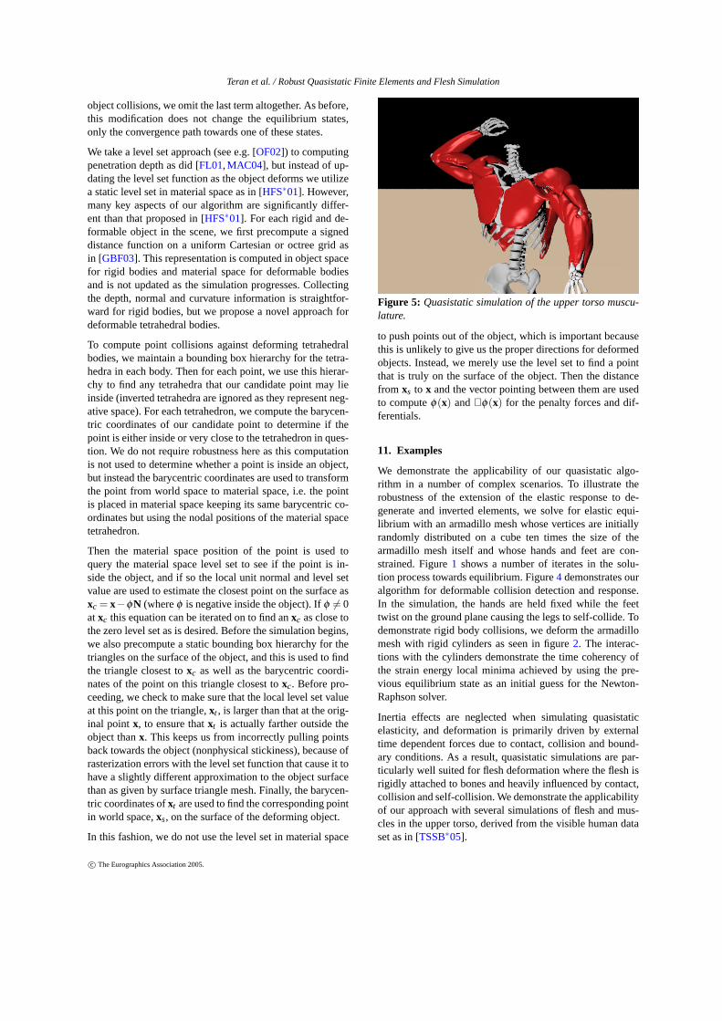
Figure 5: Quasistatic simulation of the upper torso muscu-lature.
to push points out of the object, which is important becausethis is unlikely to give us the proper directions for deformedobjects. Instead, we merely use the level set to find a pointthat is truly on the surface of the object. Then the distancefrom xs to x and the vector pointing between them are usedto computeφ(x) and∇φ(x) for the penalty forces and dif-ferentials.
11. Examples
We demonstrate the applicability of our quasistatic algo-rithm in a number of complex scenarios. To illustrate therobustness of the extension of the elastic response to de-generate and inverted elements, we solve for elastic equi-librium with an armadillo mesh whose vertices are initiallyrandomly distributed on a cube ten times the size of thearmadillo mesh itself and whose hands and feet are con-strained. Figure1 shows a number of iterates in the solu-tion process towards equilibrium. Figure4 demonstrates ouralgorithm for deformable collision detection and response.In the simulation, the hands are held fixed while the feettwist on the ground plane causing the legs to self-collide. Todemonstrate rigid body collisions, we deform the armadillomesh with rigid cylinders as seen in figure2. The interac-tions with the cylinders demonstrate the time coherency ofthe strain energy local minima achieved by using the pre-vious equilibrium state as an initial guess for the Newton-Raphson solver.
Inertia effects are neglected when simulating quasistaticelasticity, and deformation is primarily driven by externaltime dependent forces due to contact, collision and bound-ary conditions. As a result, quasistatic simulations are par-ticularly well suited for flesh deformation where the flesh isrigidly attached to bones and heavily influenced by contact,collision and self-collision. We demonstrate the applicabilityof our approach with several simulations of flesh and mus-cles in the upper torso, derived from the visible human dataset as in [TSSB∗05].
c© The Eurographics Association 2005.

Teran et al. / Robust Quasistatic Finite Elements and Flesh Simulation
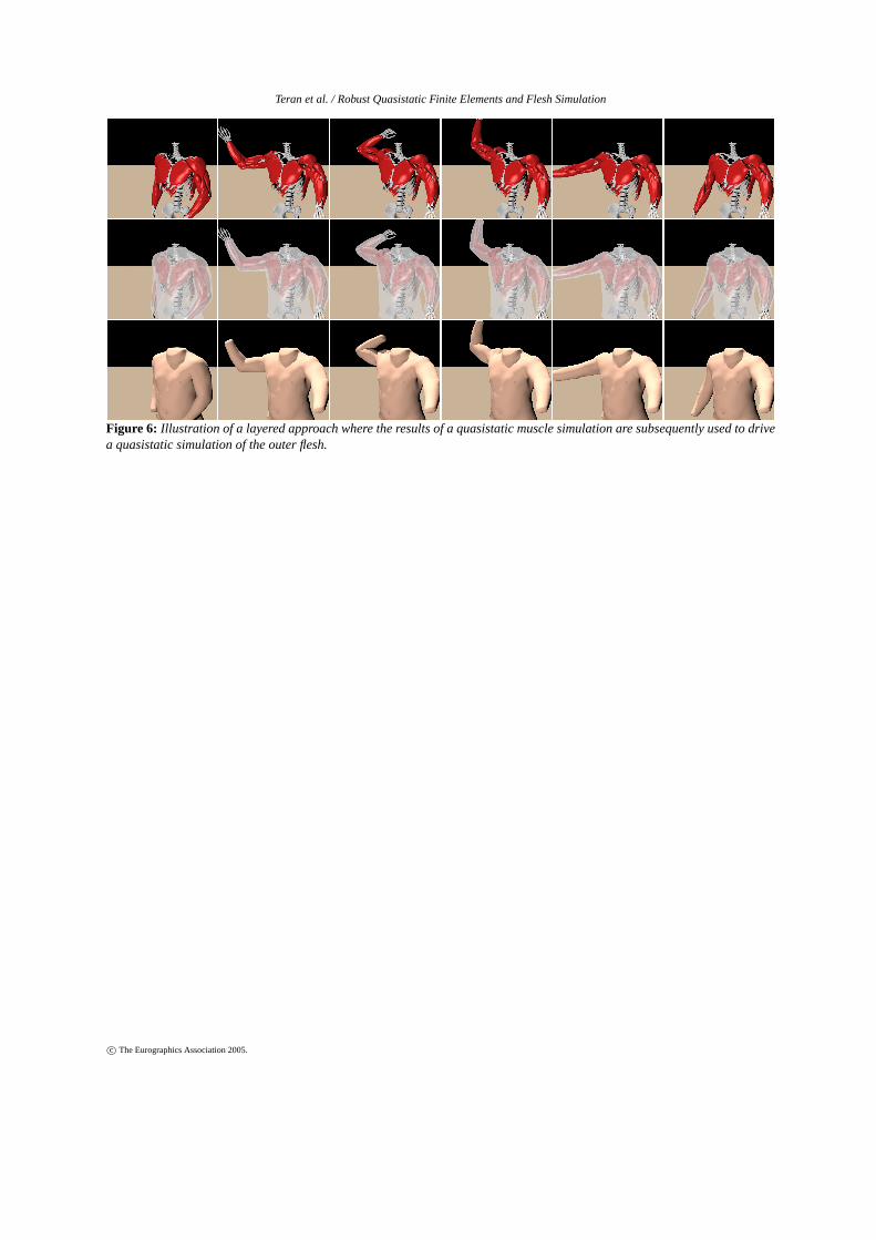
In figure3, we attach the deformable flesh directly to the un-derlying skeleton. The flesh naturally deforms from the in-fluence of the skeleton as well as from self collision, provid-ing realistic deformation and wrinkling of the outer skin. Theflesh mesh consists of 600 thousand tetrahedral elements andwas simulated with a neo-Hookean constitutive model ex-tended to the inverted regime as in [ITF04]. Figure5 showsskeletal muscle in the upper limb simulated with the mus-cle constitutive model outlined in [ITF04] and [TBNF03].Although our quasistatic formulation was only presented forisotropic materials, it is readily extended to the case of sim-ple transverse isotropy, since the strain energy is a sum of anisotropic and a transversely isotropic component with eachterm being a function of their respective associated invari-ants. This property leads to a stiffness matrix which is a sumof an isotropic term (which can be processed in the standardfashion) and a simple anisotropic term whose eigenstructureis easy to manipulate. The resulting simulations are enrichedby muscle activations that are computed from the skeletalmotion as in [TSSB∗05] to produce realistic contractile mo-tion. Finally, figure6 shows a layered approach where weuse the simulated motion of the skeletal muscles as kine-matic boundary conditions for a second flesh only simula-tion to create more realistic muscle based skin deformation.During the second simulation, flesh nodes are constrained tofollow the muscle motion if they are within a tolerance ofthe musculoskeletal surface.
The originally scattered armadillo geometry of figure1 con-sists of 380K tetrahedra and converged to steady state in80 Newton-Raphson iterations requiring 2-3 seconds each,under a neo-Hookean constitutive model (collision handlingdisabled). For the same 380K element armadillo mesh in fig-ure2 the computational cost was approximately 90 secondsper frame. The flesh mesh of figure6 consisted of 600Ktetrahedra and was simulated at 2 minutes per frame. Allsimulations were performed on a 3 GHz pentium 4 worksta-tion. We stress that these are rather large simulation meshes,and meshes on the order of 10 thousand elements can betypically simulated at rates of 5–10 frames per second (com-putational cost scales nonlinearly). This is with tight boundson the tolerance, where additional Newton-Raphson itera-tions lead to no visible changes. Additionaly, the authorsof [SNF05] use our method for a highly constrained facesimulation application and report running times that translateto approximately 30 seconds per frame for a 370K tetrahe-dron mesh with full self and rigid body collision handling, asopposed to 50 minutes per frame, on average, for a fully dy-namic simulation. Moreover, their use of quasistatic (as op-posed to dynamic) simulation allows them to construct a fullsystem Jacobian enabling the solution of an inverse problemto find muscle activations based on surface deformation.
12. Conclusions
We presented a framework for efficient and robust quasista-tic simulation of nonlinear elastic materials using a modifiedNewton-Raphson algorithm that can robustly iterate throughconfigurations that give rise to mesh inversion and buck-ling instabilities. Fast conjugate gradient solvers can be used,since we enforce positive definiteness of the modified linearequilibrium equations at each iteration. This simulation tech-nique is ideal for constrained objects influenced by the mo-tion of their specified boundary conditions. In particular, itis useful for simulating deformable flesh and skin for virtualcharacters whose motion is driven by an underlying kine-matic skeleton.
13. Acknowledgements
Research supported in part by an ONR YIP award anda PECASE award (ONR N00014-01-1-0620), a PackardFoundation Fellowship, a Sloan Research Fellowship,ONR N00014-03-1-0071, ONR N00014-02-1-0720, ARODAAD19-03-1-0331, NSF IIS-0326388, NSF ITR-0205671and NIH U54-GM072970. E.S. was supported in part by aStanford Graduate Fellowship, and G.I. was supported inpart by a National Science Foundation Graduate ResearchFellowship. We would like to thank Mike Houston, ChristosKozyrakis, Mark Horowitz, Bill Dally and Vijay Pande forcomputing resources.
References
[ACP02] ALLEN B., CURLESSB., POPOVIC Z.: Articu-lated body deformation from range scan data. InProc. ofACM SIGGRAPH 2002(2002), pp. 612–619.
[AHS03] ALBRECHT I., HABER J., SEIDEL H. P.:Construction and animation of anatomically based hu-man hand models. InProc. of the 2003 ACM SIG-GRAPH/Eurographics Symp. on Comput. Anim.(2003),pp. 98–109.
[AS96] AMBROSIOL., SONERH. M.: Level set approachto mean curvature flow in arbitrary codimension.J. ofDifferential Geometry 43(1996), 693–737.
[BFA02] BRIDSON R., FEDKIW R., ANDERSONJ.: Ro-bust treatment of collisions, contact and friction for clothanimation. ACM Trans. Graph. (SIGGRAPH Proc.) 21(2002), 594–603.
[BMF03] BRIDSON R., MARINO S., FEDKIW R.: Simu-lation of clothing with folds and wrinkles. InProc. of the2003 ACM SIGGRAPH/Eurographics Symp. on Comput.Anim.(2003), pp. 28–36.
[BW98] BARAFF D., WITKIN A.: Large steps in clothsimulation. InProc. SIGGRAPH 98(1998), pp. 1–12.
[BWK03] BARAFF D., WITKIN A., KASS M.: Untan-gling cloth. ACM Trans. Graph. (SIGGRAPH Proc.) 22(2003), 862–870.
c© The Eurographics Association 2005.
Teran et al. / Robust Quasistatic Finite Elements and Flesh Simulation
[CGC∗02a] CAPELL S., GREEN S., CURLESS B.,DUCHAMP T., POPOVIC Z.: Interactive skeleton-drivendynamic deformations.ACM Trans. Graph. (SIGGRAPHProc.) 21(2002), 586–593.
[CGC∗02b] CAPELL S., GREEN S., CURLESS B.,DUCHAMP T., POPOVIC Z.: A multiresolution frame-work for dynamic deformations. InACM SIGGRAPHSymp. on Comput. Anim.(2002), ACM Press, pp. 41–48.
[CK02] CHOI K.-J., KO H.-S.: Stable but responsivecloth. ACM Trans. Graph. (SIGGRAPH Proc.) 21(2002),604–611.
[CK05] CHOI M. G., KO H.-S.: Modal warping: Real-time simulation of large rotational deformation and ma-nipulation. IEEE Trans. Viz. Comput. Graph. 11(2005),91–101.
[CZ92] CHEN D., ZELTZER D.: Pump it up: Computeranimation of a biomechanically based model of muscleusing the finite element method.Comput. Graph. (SIG-GRAPH Proc.)(1992), 89–98.
[DCKY02] DONG F., CLAPWORTHY G., KROKOS M.,YAO J.: An anatomy-based approach to human musclemodeling and deformation.IEEE Trans. Vis. Comput.Graph. 8, 2 (2002).
[DDCB01] DEBUNNE G., DESBRUN M., CANI M.,BARR A.: Dynamic real-time deformations using space& time adaptive sampling. InProc. SIGGRAPH 2001(2001), vol. 20, pp. 31–36.
[FL01] FISHER S., LIN M. C.: Deformed distance fieldsfor simulation of non-penetrating flexible bodies. InCom-put. Anim. and Sim. ’01(2001), Proc. Eurographics Work-shop, pp. 99–111.
[GBF03] GUENDELMAN E., BRIDSON R., FEDKIW R.:Nonconvex rigid bodies with stacking. ACM Trans.Graph. (SIGGRAPH Proc.) 22, 3 (2003), 871–878.
[GHDS03] GRINSPUN E., HIRANI A., DESBRUN M.,SCHRODER P.: Discrete shells. InProc. of the 2003ACM SIGGRAPH/Eurographics Symp. on Comput. Anim.(2003), pp. 62–67.
[GKS02] GRINSPUN E., KRYSL P., SCHRODER P.:CHARMS: A simple framework for adaptive simulation.ACM Trans. Graph. (SIGGRAPH Proc.) 21(2002), 281–290.
[GMTT89] GOURRET J.-P., MAGNENAT-THALMANN
N., THALMANN D.: Simulation of object and humanskin deformations in a grasping task.Comput. Graph.(SIGGRAPH Proc.)(1989), 21–30.
[GMW81] GILL P. E., MURRAY W., WRIGHT M. H.:Practical Optimization. Academic Press, San Diego,USA, 1981.
[GW03] GUILKEY J., WEISSJ.: Implicit time integration
for the material point method: Quantitative and algorith-mics comparison with the finite element method.Int. J.Numer. Meth. Engng 57(2003), 1323–1338.
[HFS∗01] HIROTA G., FISHER S., STATE A., LEE C.,FUCHS H.: An implicit finite element method for elasticsolids in contact. InProc. of Computer Animation(2001),pp. 136–146.
[ITF04] IRVING G., TERAN J., FEDKIW R.: Invertiblefinite elements for robust simulation of large deformation.In Proc. of the ACM SIGGRAPH/Eurographics Symp. onComput. Anim.(2004), pp. 131–140.
[JF03] JAMES D., FATAHALIAN K.: Precomputing inter-active dynamic deformable scenes.ACM Trans. Graph.(SIGGRAPH Proc.) 22(2003), 879–887.
[JP02] JAMES D., PAI D.: DyRT: Dynamic response tex-tures for real time deformation simulation with graphicshardware. ACM Trans. Graph. (SIGGRAPH Proc.) 21(2002), 582–585.
[KJP02] KRY P. G., JAMES D. L., PAI D. K.: Eigenskin:real time large deformation character skinning in hard-ware. InProceedings of the ACM SIGGRAPH symposiumon Computer animation(2002), ACM Press, pp. 153–159.
[KM04] KURIHARA T., MIYATA N.: Modeling de-formable human hands from medical images. InProc. ofthe 2004 ACM SIGGRAPH/Eurographics Symp. on Com-put. Anim.(2004), pp. 365–373.
[KMGB04] KAUTZMAN R., MAIOLO A., GRIFFIN D.,BUEKER A.: Jiggly bits and motion retargetting: Bringingthe motion of Hyde to life in Van Helsing with dynam-ics. InSIGGRAPH 2004 Sketches & Applications(2004),ACM Press.
[LCF00] LEWIS J., CORDNERM., FONG N.: Pose spacedeformations: A unified approach to shape interpolationa nd skeleton-driven deformation.Comput. Graph. (SIG-GRAPH Proc.)(2000), 165–172.
[MAC04] MARCHAL D., AUBERT F., CHAILLOU
C.: Collision between deformable objects using fast-marching on tetrahedral models. InProceedings of theACM SIGGRAPH symposium on Computer animation(2004), ACM Press.
[MBF04] MOLINO N., BAO J., FEDKIW R.: A virtualnode algorithm for changing mesh topology during simu-lation.ACM Trans. Graph. (SIGGRAPH Proc.) 23(2004),385–392.
[MBTF03] MOLINO N., BRIDSON R., TERAN J., FED-KIW R.: A crystalline, red green strategy for meshinghighly deformable objects with tetrahedra. In12th Int.Meshing Roundtable(2003), pp. 103–114.
[MDM ∗02] MULLER M., DORSEY J., MCM ILLAN L.,JAGNOW R., CUTLER B.: Stable real-time deformations.
c© The Eurographics Association 2005.

Teran et al. / Robust Quasistatic Finite Elements and Flesh Simulation
In ACM SIGGRAPH Symp. on Comput. Anim.(2002),pp. 49–54.
[MG03] MOHR A., GLEICHER M.: Building efficient, ac-curate character skins from examples.ACM Transactionson Graphics 22, 3 (2003), 562–568.
[MG04] MULLER M., GROSSM.: Interactive virtual ma-terials. InGraph. Interface(May 2004), pp. 239–246.
[MKN ∗04] MULLER M., KEISER R., NEALEN A.,PAULY M., CROSSM., ALEXA M.: Point based anima-tion of elastic, plastic and melting objects. InProc. of the2004 ACM SIGGRAPH/Eurographics Symp. on Comput.Anim.(2004), pp. 141–151.
[MMDJ01] MULLER M., MCM ILLAN L., DORSEY J.,JAGNOW R.: Real-time simulation of deformation andfracture of stiff materials. InComput. Anim. and Sim. ’01(2001), Proc. Eurographics Workshop, Eurographics As-soc., pp. 99–111.
[NTHF02] NG-THOW-HING V., FIUME E.: Application-specific muscle representations. InProc. of Gr. Inter. 2002(2002), Sturzlinger W., McCool M., (Eds.), Canadian In-formation Processing Society, pp. 107–115.
[OBH02] O’BRIEN J., BARGTEIL A., HODGINS J.:Graphical modeling of ductile fracture.ACM Trans.Graph. (SIGGRAPH Proc.) 21(2002), 291–294.
[OF02] OSHER S., FEDKIW R.: Level Set Methods andDynamic Implicit Surfaces. Springer-Verlag, 2002. NewYork, NY.
[OH99] O’BRIEN J., HODGINS J.: Graphical modelingand animation of brittle fracture. InProc. SIGGRAPH 99(1999), vol. 18, pp. 137–146.
[PDA01] PICINBONO G., DELINGETTE H., AYACHE N.:Non-linear and anisotropic elastic soft tissue models formedical simulation. InIEEE Int. Conf. Robot. and Au-tomation(2001).
[SNF05] SIFAKIS E., NEVEROV I., FEDKIW R.: Au-tomatic determination of facial muscle activations fromsparse motion capture marker data.to appear in ACMTrans. Graph. (SIGGRAPH Proc.)(2005).
[SPCM97] SCHEEPERSF., PARENT R., CARLSON W.,MAY S.: Anatomy-based modeling of the human muscu-lature.Comput. Graph. (SIGGRAPH Proc.)(1997), 163–172.
[SRC01] SLOAN P., ROSE C., COHEN M.: Shape by ex-ample. InProc. of 2001 Symp. Int. 3D Graph.(2001),pp. 135–143.
[ST04] STINSON W., THURIOT P.: Bulging muscle andsliding skin: Deformation systems for Hellboy. InSIG-GRAPH 2004 Sketches & Applications(2004), ACMPress.
[TBNF03] TERAN J., BLEMKER S., NG V., FEDKIW R.:
Finite volume methods for the simulation of skeletal mus-cle. InProc. of the 2003 ACM SIGGRAPH/EurographicsSymp. on Comput. Anim.(2003), pp. 68–74.
[TF88a] TERZOPOULOSD., FLEISCHERK.: Deformablemodels.The Visual Computer, 4 (1988), 306–331.
[TF88b] TERZOPOULOSD., FLEISCHER K.: Modelinginelastic deformation: viscoelasticity, plasticity, fracture.Comput. Graph. (SIGGRAPH Proc.)(1988), 269–278.
[THMG04] TESCHNER M., HEIDELBERGER B.,MULLER M., GROSSM.: A versatile and robust modelfor geometrically complex deformable solids. InProc.Computer Graphics International(2004), pp. 312–319.
[TPBF87] TERZOPOULOS D., PLATT J., BARR A.,FLEISCHERK.: Elastically deformable models.Comput.Graph. (Proc. SIGGRAPH 87) 21, 4 (1987), 205–214.
[TSSB∗05] TERAN J., SIFAKIS E., SALINAS -BLEMKER
S., NG-THOW-HING V., LAU C., FEDKIW R.: Creat-ing and simulating skeletal muscle from the visible humandata set.IEEE Trans. on Vis. and Comput. Graph. 11, 3(2005), 317–328.
[TW88] TERZOPOULOS D., WITKIN A.: Physicallybased models with rigid and deformable components. InGraphics Interface(1988), pp. 146–154.
[TWS80] TAYLOR R., WILSON E., SACKET S.: Directsolution of equations by frontal and variable band activecolumn methods. InEurope-U.S. Workshop: NonlinearFinite Element Analysis in Structural Mechanics(1980),Springer-Verlag.
[VT00] VOLINO P., THALMAN N.: Implementing fastcloth simulation with collision response. InProceedingsof the International Conference on Computer Graphics(2000), IEEE Computer Society, p. 257.
[WP02] WANG X. C., PHILLIPS C.: Multi-weight en-veloping: Least-squares approximation techniques forskin animation. InProc. ACM SIGGRAPH Symposiumon Computer Animation(2002), pp. 129–138.
[WV97] WILHELMS J., VAN GELDER A.: Anatomicallybased modeling. Comput. Graph. (SIGGRAPH Proc.)(1997), 173–180.
[ZCK98] ZHU Q., CHEN Y., KAUFMAN A.: Real-timebiomechanically-based muscle volume deformation usingFEM. Comput. Graph. Forum 190, 3 (1998), 275–284.
c© The Eurographics Association 2005.
Teran et al. / Robust Quasistatic Finite Elements and Flesh Simulation
Figure 6: Illustration of a layered approach where the results of a quasistatic muscle simulation are subsequently used to drivea quasistatic simulation of the outer flesh.
c© The Eurographics Association 2005.