Frequency Synchronization Algorithm for OFDM over Frequency Selective Fading
Circuits Syst Signal Process (2014) 33:2475–2493DOI 10.1007/s00034-014-9747-z
Robust and Efficient OFDM Synchronization forFPGA-Based Radios
Thinh Hung Pham · Ian V. McLoughlin ·Suhaib A. Fahmy
Received: 15 July 2013 / Revised: 9 January 2014 / Published online: 15 February 2014© Springer Science+Business Media New York 2014
Abstract Orthogonal frequency division multiplexing (OFDM) is a popular modu-lation technique that can combat impulsive noise, is robust to multipath fading, isspectrally efficient, and can allow flexible allocation of spectrum. It has become a keystandard in cognitive radio systems as well as an enabling technology for mobile dataaccess systems. An OFDM receiver’s performance is heavily impacted by the accu-racy of its symbol timing offset (STO) and carrier frequency offset (CFO) estimation.This paper proposes a novel OFDM synchronization method that combines robustperformance with computational efficiency. FPGA prototyping is used to explore thetrade-off between the number of computations to be performed and computation wordlength with respect to both synchronization performance and power consumption.Through simulation, the proposed method is shown to provide accurate fractionalCFO estimation as well as STO estimation in a range of channels. In particular, itcan yield excellent synchronization performance in the face of a CFO that is largerthan many state-of-the-art synchronization implementations can handle. The systemimplementation demonstrates efficient resource usage and reduced power consump-tion compared with existing methods, and this is explored as a fine-grained trade-offbetween performance and power consumption. The result is a robust method suitablefor use in low-power radios, enabling less precise analog front ends to be used.
T. H. Pham · S. A. FahmySchool of Computer Engineering, Nanyang Technological University, Nanyang Avenue,Singapore 639798, Singaporee-mail: [email protected]
S. A. Fahmye-mail: [email protected]
I. V. McLoughlin (B)School of Information Science and Technology, The University of Science and Technology of China,Hefei 230027, Anhui, Chinae-mail: [email protected]
2476 Circuits Syst Signal Process (2014) 33:2475–2493
Keywords OFDM · Synchronization · OFDM Implementation · FPGA ·IEEE 802.16 · Software defined radio
1 Introduction
Orthogonal frequency division multiplexing (OFDM) is an effective modulation tech-nique that has been used in both wired and wireless communication systems. Itsadvantages of combating impulsive noise, its robustness to multipath effects, and itsspectral efficiency have led to OFDM being chosen for various high-bit-rate wire-less transmission systems such as wireless local area networks (WLAN) defined inIEEE 802.11 and the metropolitan area networks (MAN) in IEEE 802.16. OFDMis also a key modulation scheme for cognitive radios systems [15] where it providesrobustness in frequency selective channels and the ability to employ spectrum pooling,where unlicensed users may temporarily access spectrum resources during licensedusers’ idle periods, thus facilitating dynamic spectrum access (DSA) networks. How-ever, OFDM performance is sensitive to receiver synchronization; carrier frequencyoffset (CFO) causes inter-carrier interference, and errors in timing synchronizationcan lead to inter-symbol interference [6]. Therefore, synchronization is critical to theperformance of OFDM systems.
Many techniques have been proposed for effective OFDM synchronization. Thetwo different transmission modes, continuous mode and burst packet mode, may alsorequire different synchronization schemes [1]. In this paper, we investigate synchro-nization for burst packet mode, in which all OFDM frames begin with preamblesymbols, and both frequency offset estimation and timing synchronization have to becompleted within the duration of this preamble. Exploiting the characteristic pream-ble symbol of two identical halves, Schmidl and Cox [18] introduced metrics forautocorrelation-based synchronization, which can be computed iteratively at low costand is robust to frequency offset. However, the resulting metric exhibits a plateauwhich leads to some uncertainty in determining the start of a frame. It is also limitedin terms of CFO estimation.
Kim and Park [9] proposed a method to improve the robustness of fine STO esti-mation in the face of large CFO. The method applies multiple cross-correlations withpre-rotation by all possible integer CFOs to calculate fine STO, assuming integer CFOis less than ±6 sub-carrier spacings. However, the method is unsuited to large CFOoffsets, and the computational cost is significant since all possible integer CFOs mustbe calculated.
Kishore and Reddy [10] introduced new metrics based on cross-correlation betweenthe known and received preamble symbols. These can accurately determine start offrame even at low signal-to-noise ratios (SNRs). Moreover, the method is robust tolarge CFO. However, the cross-correlation operation used in this method is compu-tationally expensive, limiting suitability for implementation, especially in low-powersystems.
This paper proposes a revised synchronization approach which supports the IEEE802.16-2009 preamble [8]. It is robust to large frequency offset, has accurate STOestimation, and is computationally efficient. The novel method is presented along
Circuits Syst Signal Process (2014) 33:2475–2493 2477
with simulations to demonstrate performance. As cognitive radios are increasinglybeing built using FPGAs [12,20], we then present results for an FPGA implementationwith an analysis of computational complexity compared against other state-of-the-artmethods.
In summary, the novel method involves a reformation of the synchronizationsequence, a widened synchronization search space, and a computation engine thatcan formulate the timing metrics with a significant efficiency improvement over exist-ing methods.
This paper is organized as follows: Sect. 2 discusses OFDM synchronization andoutlines the proposed method, which is then simulated and evaluated in Sect. 3. Thehardware implementation is presented and discussed in Sect. 4 and Sect. 5 concludesthe paper.
2 OFDM Synchronization
We first investigate two state-of-the-art OFDM synchronization methods in terms ofperformance and computational complexity, before presenting our proposed methodand evaluating it.
2.1 Existing Methods
Autocorrelation-based approaches are commonly preferred for implementing synchro-nization in practical systems due to low computational complexity [5,11,13,21]. Thestate-of-the-art scheme in [7,17,19] uses autocorrelation-based timing metrics initiallypresented in [18] for frame detection, coarse STO, and fractional CFO estimation, fol-lowed by an additional cross-correlation to compute fine STO and integer CFO.
These timing metrics are defined as:
P(d) =L−1∑
m=0
(r∗d+mrd+m+L)
R(d) =L−1∑
m=0
|rd+m+L |2
M(d) = |P(d)|2(R(d))2 , (1)
where d denotes a time index corresponding to the first sample in a window of 2Lsamples of received signal r , and ∗ denotes complex conjugation. The M(d) metricforms a plateau when the preamble is present in the received window [18]. In imple-mentation, these metrics are generally most efficient to compute in a recursive manneras follows:
P(d + 1) = P(d) + (r∗d+Lrd+2L) − (r∗
d rd+L)
R(d + 1) = R(d) + |rd+2L |2 − |rd+L |2 (2)
2478 Circuits Syst Signal Process (2014) 33:2475–2493
The presence of the preamble can be detected by thresholding the magnitude ofM(d). After detecting the frame, the fractional CFO is estimated based on the angleof the P(d) metric [18]. Before the fine STO estimation is performed using cross-correlation—which is sensitive to CFO—the estimated fractional CFO must be com-pensated by time-domain phase de-rotation of the received samples.
The purpose of timing synchronization is to find a correct starting point for thediscrete Fourier transform (DFT) window used by the receiver for demodulation.It should be noted that coarse time synchronization using autocorrelation (men-tioned above) does not consistently detect the correct starting point; therefore, fineSTO estimation is necessary for accurate timing synchronization. This can be foundaccurately by cross-correlating the received samples with the known preamble todetect the peak which occurs when the received samples match the known pream-ble. Unfortunately, this requires a significant amount of high-speed computation.One way of reducing the overhead of cross-correlation is to use a sign-bit mul-tiplier [19] in place of a full word multiplier. However, this is highly sensitive toCFO.
In practice, fractional CFO can be effectively estimated using autocorrelation onlywithin a limited range; in the case of the IEEE 802.16 preamble, up to ±2 sub-carrierspacings [9]. If the CFO is outside this range, integer CFO has been introduced as amultiple of the coarse CFO’s range. This integer CFO is most commonly estimatedby frequency-domain cross-correlation [2,9]. However, a critical problem arises if theCFO is larger than the range of the coarse CFO. In this case, fractional CFO estimationdoes not correctly estimate the CFO, and hence it is not suitably compensated, leadingto a degradation in fine STO performance.
Previous implementations of such systems tend to assume that CFO is less than therange of the coarse CFO [3,5,7,13,17,19]. However, this necessitates highly accuratetiming at the RF interface, which translates to increased system cost. While the methodgenerally works well and copes with low SNR, it can only operate when the CFO iswithin a limited range.
Kishore and Reddy [10] presented an alternative method using cross-correlation-based timing metrics between the known transmitted and received preamble sym-bols. These metrics are defined similarly to those in [18] but the P(d) metric isreformulated to rely on cross-correlation; cross-correlation presents distinct peakscorresponding to when the received samples match the known transmitted pream-ble samples. A frame is detected when M crosses a threshold and the start offrame is estimated by searching for peaks in M . This method can accurately deter-mine the start of a frame even at low SNR. Moreover, this method is robust tolarge CFO for time synchronization. Simulations in [10] show that time synchro-nization can be performed with a CFO of up to 10.5 carrier spacings. The pricefor this performance is that cross-correlation requires complex computation and alarge number of multiplications are involved. This can be alleviated to some extentby using a multiplierless correlator [22] (as mentioned above), at the expense ofa degraded P metric which is used to estimate frequency offset. So, although thismethod presents a useful solution, it is hampered in practice by computational com-plexity issues. As a result, no practical implementation of that scheme has beenreported.
Circuits Syst Signal Process (2014) 33:2475–2493 2479
Sample index
Val
ue o
f T
imin
g M
etri
c
P' R'
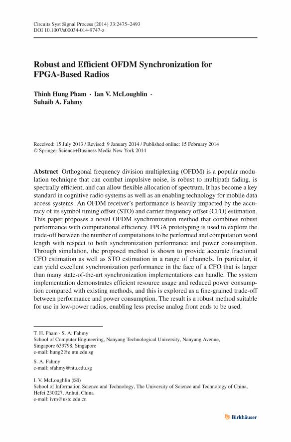
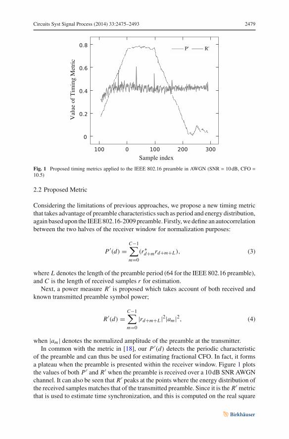
Fig. 1 Proposed timing metrics applied to the IEEE 802.16 preamble in AWGN (SNR = 10 dB, CFO =10.5)
2.2 Proposed Metric
Considering the limitations of previous approaches, we propose a new timing metricthat takes advantage of preamble characteristics such as period and energy distribution,again based upon the IEEE 802.16-2009 preamble. Firstly, we define an autocorrelationbetween the two halves of the receiver window for normalization purposes:
P ′(d) =C−1∑
m=0
(r∗d+mrd+m+L), (3)
where L denotes the length of the preamble period (64 for the IEEE 802.16 preamble),and C is the length of received samples r for estimation.
Next, a power measure R′ is proposed which takes account of both received andknown transmitted preamble symbol power;
R′(d) =C−1∑
m=0
|rd+m+L |2|am |2, (4)
when |am | denotes the normalized amplitude of the preamble at the transmitter.In common with the metric in [18], our P ′(d) detects the periodic characteristic
of the preamble and can thus be used for estimating fractional CFO. In fact, it formsa plateau when the preamble is presented within the receiver window. Figure 1 plotsthe values of both P ′ and R′ when the preamble is received over a 10 dB SNR AWGNchannel. It can also be seen that R′ peaks at the points where the energy distribution ofthe received samples matches that of the transmitted preamble. Since it is the R′ metricthat is used to estimate time synchronization, and this is computed on the real square
2480 Circuits Syst Signal Process (2014) 33:2475–2493
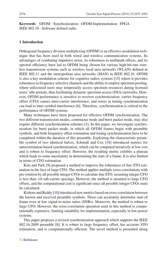
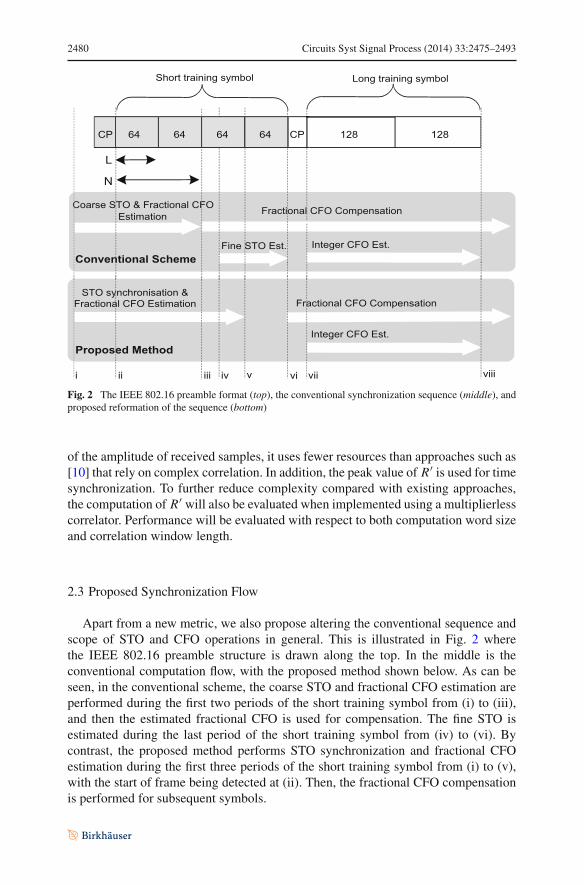
Fig. 2 The IEEE 802.16 preamble format (top), the conventional synchronization sequence (middle), andproposed reformation of the sequence (bottom)
of the amplitude of received samples, it uses fewer resources than approaches such as[10] that rely on complex correlation. In addition, the peak value of R′ is used for timesynchronization. To further reduce complexity compared with existing approaches,the computation of R′ will also be evaluated when implemented using a multiplierlesscorrelator. Performance will be evaluated with respect to both computation word sizeand correlation window length.
2.3 Proposed Synchronization Flow
Apart from a new metric, we also propose altering the conventional sequence andscope of STO and CFO operations in general. This is illustrated in Fig. 2 wherethe IEEE 802.16 preamble structure is drawn along the top. In the middle is theconventional computation flow, with the proposed method shown below. As can beseen, in the conventional scheme, the coarse STO and fractional CFO estimation areperformed during the first two periods of the short training symbol from (i) to (iii),and then the estimated fractional CFO is used for compensation. The fine STO isestimated during the last period of the short training symbol from (iv) to (vi). Bycontrast, the proposed method performs STO synchronization and fractional CFOestimation during the first three periods of the short training symbol from (i) to (v),with the start of frame being detected at (ii). Then, the fractional CFO compensationis performed for subsequent symbols.
Circuits Syst Signal Process (2014) 33:2475–2493 2481
The method used for synchronization based upon these metrics is as follows: First,frame detection is performed by comparing P ′ to R′ with a threshold ζ :
|P ′(d)| > ζ × R′(d). (5)
In order to increase stability, a frame is detected when condition (5) is met for nconsecutive samples (with n = 4 used throughout this paper). The threshold is differentfor each channel and needs to be determined empirically by simulation, in commonwith many other systems, such as [10]. If the threshold is too small, noise may causea failure of detection. Otherwise, if it is too large, the frame detection may be missed.Assuming the channel characteristics are known, the threshold can be selected froma lookup table in a practical system. After a frame is detected, the starting point ofthe short preamble is found by searching for the peaks in R′(d). As can be seen inFig. 1, two peaks in R′(d) will bracket the transition to the plateau in P ′(d) shown atsample indices of −31 and 33, respectively. The second peak is used to determine thestarting point for the DFT window. This is accomplished for the maximum values ofR′(d)+ R′(d − L) over the next L samples after frame detection. Secondly, fractionalCFO estimation and correction is based on the P ′(d) metric and phase rotation as inother work [5,7,13,17–19].
In this proposed method, the fractional CFO is estimated within the preamble toensure that the correct angle of P ′(d) is then available for use in the estimation process.Thus, the estimated fractional CFO will tend to be more accurate as a result. Moreover,this method separates the length of the preamble period, L , from the length of receivedsamples for estimation, C , and as a result, L can be shortened to extend the range offractional CFO, while C can be lengthened to increase robustness to channel noise.For the IEEE 802.16 preamble, C can be in the range of L to 3L to improve overallsynchronization precision, but clearly entails more computation when extended. InSect. 3, which investigates the performance of the proposed method, a suitable valueof C is chosen in order to obtain a good trade-off between accuracy and hardware cost.
3 Simulation
We evaluate the performance of the proposed synchronization method, applied to theIEEE 802.16-2009 downlink preamble, in MATLAB under both AWGN channels andmore realistic SUI channels that are widely used in the literature [9,10].
The Stanford University Interim (SUI) channel model [4] is used to simulate a fre-quency selective channel and takes into account many wireless channel effects includ-ing delay spread, Doppler spread, phase noise, and channel interference. In addition,the value of metrics computed in MATLAB is later verified with corresponding valuesfrom the FPGA simulation, to ensure practical functional equivalence.
In total, 100,000 OFDM frames, preceded by noise with randomly seeded AWGNand followed by preamble and data symbols, are used to evaluate synchronizationperformance for each method. The proposed method is compared to the state-of-the-art methods, in terms of accuracy of both time synchronization and fractionalCFO estimation. The performance of STO estimation is measured in terms of failure
2482 Circuits Syst Signal Process (2014) 33:2475–2493
SNR (dB)
Failr
ate
of f
ram
e sy
nchr
onis
atio
n (%
)
Prop3 Prop2 Prop1SoA K&R
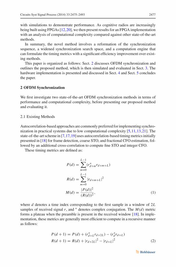
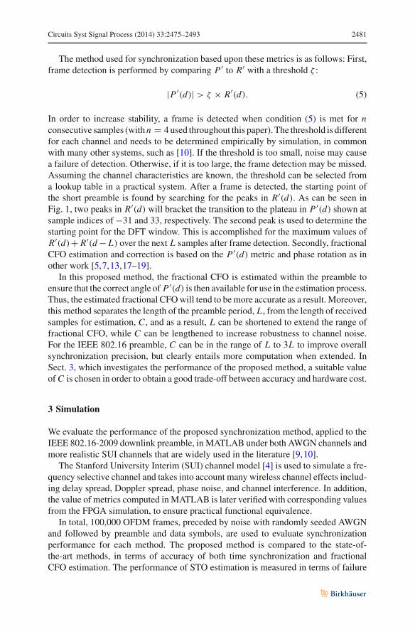
Fig. 3 Performance of time synchronization in AWGN channels with a frequency offset of 0.5 timesubcarrier spacing
rate (%), and the accuracy of CFO estimation is evaluated in terms of mean squareerror (MSE). We separately evaluate the robustness of time synchronization againstlarge CFO for each method. Three versions of the proposed approach are constructedby varying the length, C , of received samples for estimation based on (3). These areinvestigated to determine the trade-off between accuracy and computational cost, withC defined as follows in each case:
– Prop 1: C = L– Prop 2: C = 2L– Prop 3: C = 3L
These are compared to the state-of-the-art method (denoted as SoA) [11,17] and themethod of Kishore and Reddy [10] (denoted as K&R) for a number of evaluation sce-narios. First, the performance of each method is found for AWGN channels beginningwith CFO = 0.5, then AWGN channels with CFO varying from −10 to +10 timescarrier spacing, then SUI1, and finally SUI2 channels.
3.1 Performance in AWGN
Figures 3 and 4 plot the performance results of STO and CFO estimation in AWGNwith a frequency offset of 0.5 subcarrier spacings, respectively. SoA and the proposedmethods have much better performance than K&R in these tests, achieving perfectsynchronization when SNR exceeds 5 dB. Prop1’s STO estimation has slightly betteraccuracy with SNR below 3 dB but is worse at higher SNR than SoA. Increasingthe length of received samples for estimation, i.e., setting C = 2L , allows Prop2 to
Circuits Syst Signal Process (2014) 33:2475–2493 2483
MSE
of
Frac
tiona
l CFO
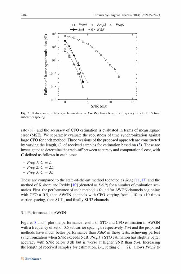
Prop3 Prop2 Prop1SoA K&R
SNR (dB)
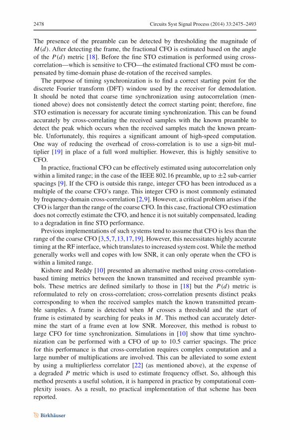
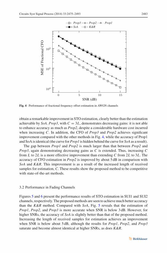
Fig. 4 Performance of fractional frequency offset estimation in AWGN channels
obtain a remarkable improvement in STO estimation, clearly better than the estimationachievable by SoA. Prop3, with C = 3L , demonstrates decreasing gains: it is not ableto enhance accuracy as much as Prop2, despite a considerable hardware cost incurredwhen increasing C . In addition, the CFO of Prop3 and Prop2 achieves significantimprovement compared with the other methods in Fig. 4, while the accuracy of Prop1and SoA is identical (the curve for Prop1 is hidden behind the curve for SoA as a result).
The gap between Prop1 and Prop2 is much larger than that between Prop2 andProp3, again demonstrating decreasing gains as C is extended. Thus, increasing Cfrom L to 2L is a more effective improvement than extending C from 2L to 3L . Theaccuracy of CFO estimation in Prop2 is improved by about 5 dB in comparison withSoA and K&R. This improvement is as a result of the increased length of receivedsamples for estimation, C. These results show the proposed method to be competitivewith state-of-the-art methods.
3.2 Performance in Fading Channels
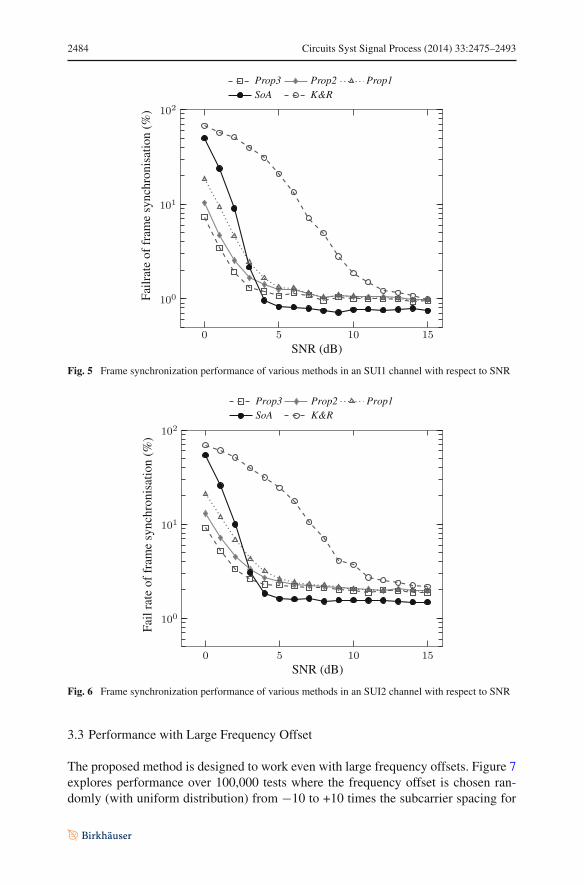
Figures 5 and 6 present the performance results of STO estimation in SUI1 and SUI2channels, respectively. The proposed methods are seen to achieve much better accuracythan the K&R method. Compared with SoA, Fig. 5 reveals that the estimation ofProp1, Prop2, and Prop3 is more accurate when SNR is below 3 dB. However, forhigher SNRs, the accuracy of SoA is slightly better than that of the proposed method.Increasing the length of received samples for estimation achieves an improvementwhen SNR is below about 5 dB, although the results for Prop1, Prop2, and Prop3saturate and become almost identical at higher SNRs, as does K&R.
2484 Circuits Syst Signal Process (2014) 33:2475–2493
SNR (dB)
Failr
ate
of f
ram
e sy
nchr
onis
atio
n (%
)
Prop3 Prop2 Prop1SoA K&R
Fig. 5 Frame synchronization performance of various methods in an SUI1 channel with respect to SNR
SNR (dB)
Fail
rate
offr
ame
sync
hron
isat
ion
(%)
Prop3 Prop2 Prop1SoA K&R
Fig. 6 Frame synchronization performance of various methods in an SUI2 channel with respect to SNR
3.3 Performance with Large Frequency Offset
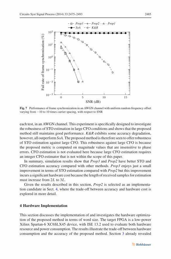
The proposed method is designed to work even with large frequency offsets. Figure 7explores performance over 100,000 tests where the frequency offset is chosen ran-domly (with uniform distribution) from −10 to +10 times the subcarrier spacing for
Circuits Syst Signal Process (2014) 33:2475–2493 2485
SNR (dB)
Fail
rate
offr
ame
sync
hron
isat
ion
(%)
Prop3 Prop2 Prop1SoA K&R
Fig. 7 Performance of frame synchronization in an AWGN channel with uniform random frequency offsetvarying from −10 to 10 times carrier spacing, with respect to SNR
each test, in an AWGN channel. This experiment is specifically designed to investigatethe robustness of STO estimation in large CFO conditions and shows that the proposedmethod still maintains good performance. K&R exhibits some accuracy degradation,however, all outperform SoA. The proposed method is therefore seen to offer robustnessof STO estimation against large CFO. This robustness against large CFO is becausethe proposed metric is computed on magnitude values that are insensitive to phaseerrors. CFO estimation is not evaluated here because large CFO estimation requiresan integer CFO estimator that is not within the scope of this paper.
In summary, simulation results show that Prop3 and Prop2 have better STO andCFO estimation accuracy compared with other methods. Prop3 enjoys just a smallimprovement in terms of STO estimation compared with Prop2 but this improvementincurs a significant hardware cost because the length of received samples for estimationmust increase from 2L to 3L .
Given the results described in this section, Prop2 is selected as an implementa-tion candidate in Sect. 4, where the trade-off between accuracy and hardware cost isexplored in more detail.
4 Hardware Implementation
This section discusses the implementation of and investigates the hardware optimiza-tion of the proposed method in terms of word size. The target FPGA is a low-powerXilinx Spartan-6 XC6SLX45 device, with ISE 13.2 used to evaluate both hardwareresource and power consumption. The results illustrate the trade-off between hardwareconsumption and the accuracy of the proposed method. Section 3 already revealed
2486 Circuits Syst Signal Process (2014) 33:2475–2493
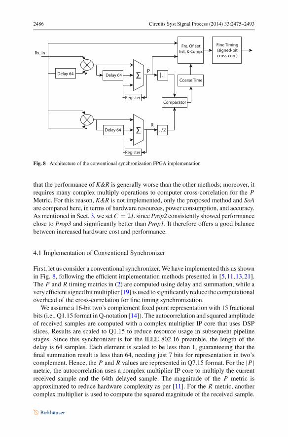
Fig. 8 Architecture of the conventional synchronization FPGA implementation
that the performance of K&R is generally worse than the other methods; moreover, itrequires many complex multiply operations to computer cross-correlation for the PMetric. For this reason, K&R is not implemented, only the proposed method and SoAare compared here, in terms of hardware resources, power consumption, and accuracy.As mentioned in Sect. 3, we set C = 2L since Prop2 consistently showed performanceclose to Prop3 and significantly better than Prop1. It therefore offers a good balancebetween increased hardware cost and performance.
4.1 Implementation of Conventional Synchronizer
First, let us consider a conventional synchronizer. We have implemented this as shownin Fig. 8, following the efficient implementation methods presented in [5,11,13,21].The P and R timing metrics in (2) are computed using delay and summation, while avery efficient signed bit multiplier [19] is used to significantly reduce the computationaloverhead of the cross-correlation for fine timing synchronization.
We assume a 16-bit two’s complement fixed point representation with 15 fractionalbits (i.e., Q1.15 format in Q-notation [14]). The autocorrelation and squared amplitudeof received samples are computed with a complex multiplier IP core that uses DSPslices. Results are scaled to Q1.15 to reduce resource usage in subsequent pipelinestages. Since this synchronizer is for the IEEE 802.16 preamble, the length of thedelay is 64 samples. Each element is scaled to be less than 1, guaranteeing that thefinal summation result is less than 64, needing just 7 bits for representation in two’scomplement. Hence, the P and R values are represented in Q7.15 format. For the |P|metric, the autocorrelation uses a complex multiplier IP core to multiply the currentreceived sample and the 64th delayed sample. The magnitude of the P metric isapproximated to reduce hardware complexity as per [11]. For the R metric, anothercomplex multiplier is used to compute the squared magnitude of the received sample.
Circuits Syst Signal Process (2014) 33:2475–2493 2487
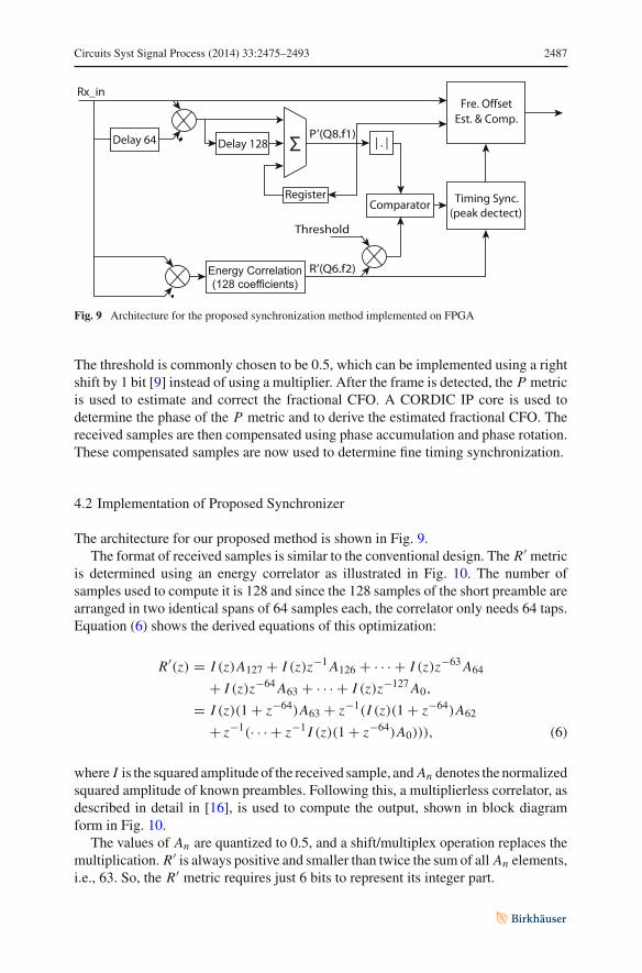
Fig. 9 Architecture for the proposed synchronization method implemented on FPGA
The threshold is commonly chosen to be 0.5, which can be implemented using a rightshift by 1 bit [9] instead of using a multiplier. After the frame is detected, the P metricis used to estimate and correct the fractional CFO. A CORDIC IP core is used todetermine the phase of the P metric and to derive the estimated fractional CFO. Thereceived samples are then compensated using phase accumulation and phase rotation.These compensated samples are now used to determine fine timing synchronization.
4.2 Implementation of Proposed Synchronizer
The architecture for our proposed method is shown in Fig. 9.The format of received samples is similar to the conventional design. The R′ metric
is determined using an energy correlator as illustrated in Fig. 10. The number ofsamples used to compute it is 128 and since the 128 samples of the short preamble arearranged in two identical spans of 64 samples each, the correlator only needs 64 taps.Equation (6) shows the derived equations of this optimization:
R′(z) = I (z)A127 + I (z)z−1 A126 + · · · + I (z)z−63 A64
+ I (z)z−64 A63 + · · · + I (z)z−127 A0,
= I (z)(1 + z−64)A63 + z−1(I (z)(1 + z−64)A62
+ z−1(· · · + z−1 I (z)(1 + z−64)A0))), (6)
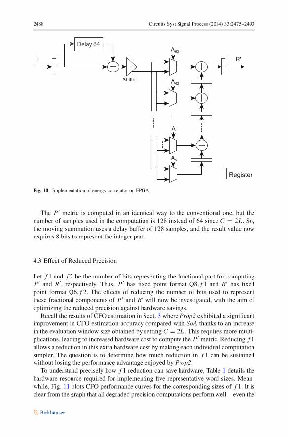
where I is the squared amplitude of the received sample, and An denotes the normalizedsquared amplitude of known preambles. Following this, a multiplierless correlator, asdescribed in detail in [16], is used to compute the output, shown in block diagramform in Fig. 10.
The values of An are quantized to 0.5, and a shift/multiplex operation replaces themultiplication. R′ is always positive and smaller than twice the sum of all An elements,i.e., 63. So, the R′ metric requires just 6 bits to represent its integer part.
2488 Circuits Syst Signal Process (2014) 33:2475–2493
Fig. 10 Implementation of energy correlator on FPGA
The P ′ metric is computed in an identical way to the conventional one, but thenumber of samples used in the computation is 128 instead of 64 since C = 2L . So,the moving summation uses a delay buffer of 128 samples, and the result value nowrequires 8 bits to represent the integer part.
4.3 Effect of Reduced Precision
Let f 1 and f 2 be the number of bits representing the fractional part for computingP ′ and R′, respectively. Thus, P ′ has fixed point format Q8. f 1 and R′ has fixedpoint format Q6. f 2. The effects of reducing the number of bits used to representthese fractional components of P ′ and R′ will now be investigated, with the aim ofoptimizing the reduced precision against hardware savings.
Recall the results of CFO estimation in Sect. 3 where Prop2 exhibited a significantimprovement in CFO estimation accuracy compared with SoA thanks to an increasein the evaluation window size obtained by setting C = 2L . This requires more multi-plications, leading to increased hardware cost to compute the P ′ metric. Reducing f 1allows a reduction in this extra hardware cost by making each individual computationsimpler. The question is to determine how much reduction in f 1 can be sustainedwithout losing the performance advantage enjoyed by Prop2.
To understand precisely how f 1 reduction can save hardware, Table 1 details thehardware resource required for implementing five representative word sizes. Mean-while, Fig. 11 plots CFO performance curves for the corresponding sizes of f 1. It isclear from the graph that all degraded precision computations perform well—even the
Circuits Syst Signal Process (2014) 33:2475–2493 2489
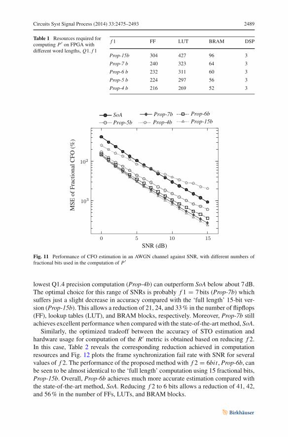
Table 1 Resources required forcomputing P ′ on FPGA withdifferent word lengths, Q1. f 1
f 1 FF LUT BRAM DSP
Prop-15b 304 427 96 3
Prop-7 b 240 323 64 3
Prop-6 b 232 311 60 3
Prop-5 b 224 297 56 3
Prop-4 b 216 269 52 3
MS
E o
f F
ract
iona
l CF
O (
%)
SoAProp-4bProp-5b
Prop-6bProp-7bProp-15b
SNR (dB)
Fig. 11 Performance of CFO estimation in an AWGN channel against SNR, with different numbers offractional bits used in the computation of P ′
lowest Q1.4 precision computation (Prop-4b) can outperform SoA below about 7 dB.The optimal choice for this range of SNRs is probably f 1 = 7 bits (Prop-7b) whichsuffers just a slight decrease in accuracy compared with the ‘full length’ 15-bit ver-sion (Prop-15b). This allows a reduction of 21, 24, and 33 % in the number of flipflops(FF), lookup tables (LUT), and BRAM blocks, respectively. Moreover, Prop-7b stillachieves excellent performance when compared with the state-of-the-art method, SoA.
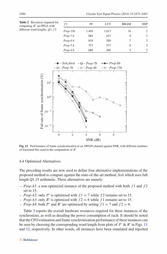
Similarly, the optimized tradeoff between the accuracy of STO estimation andhardware usage for computation of the R′ metric is obtained based on reducing f 2.In this case, Table 2 reveals the corresponding reduction achieved in computationresources and Fig. 12 plots the frame synchronization fail rate with SNR for severalvalues of f 2. The performance of the proposed method with f 2 = 6bit , Prop-6b, canbe seen to be almost identical to the ‘full length’ computation using 15 fractional bits,Prop-15b. Overall, Prop-6b achieves much more accurate estimation compared withthe state-of-the-art method, SoA. Reducing f 2 to 6 bits allows a reduction of 41, 42,and 56 % in the number of FFs, LUTs, and BRAM blocks.
2490 Circuits Syst Signal Process (2014) 33:2475–2493
Table 2 Resources required forcomputing R′ on FPGA withdifferent word lengths, Q1. f 2
f 2 FF LUT BRAM DSP
Prop-15b 1,404 1,017 16 2
Prop-7 b 884 633 8 2
Prop-6 b 818 589 7 2
Prop-5 b 753 537 6 2
Prop-4 b 689 504 5 2
SNR (dB)
Fail
rate
offr
ame
sync
hron
isat
ion
(%)
SoA,thickProp-4bProp-5b
Prop-6bProp-7bProp-15b
Fig. 12 Performance of frame synchronization in an AWGN channel against SNR, with different numbersof fractional bits used in the computation of R′
4.4 Optimized Alternatives
The preceding results are now used to define four alternative implementations of theproposed method to compare against the state-of-the-art method, SoA which uses fulllength Q1.15 arithmetic. These alternatives are namely:
– Prop-A1: a non-optimized instance of the proposed method with both f 1 and f 2set to 15.
– Prop-A2: only P ′ is optimized with f 1 = 7 while f 2 remains set to 15.– Prop-A3: only R′ is optimized with f 2 = 6 while f 1 remains set to 15.– Prop-A4: both P ′ and R′ are optimized by setting f 1 = 7 and f 2 = 6.
Table 3 reports the overall hardware resources required for these instances of thesynchronizer, as well as detailing the power consumption of each. It should be notedthat the CFO estimation and frame synchronization performance of these instances canbe seen by choosing the corresponding word length from plots of P ′ & R′ in Figs. 11and 12, respectively. In other words, all instances have been simulated and reported
Circuits Syst Signal Process (2014) 33:2475–2493 2491
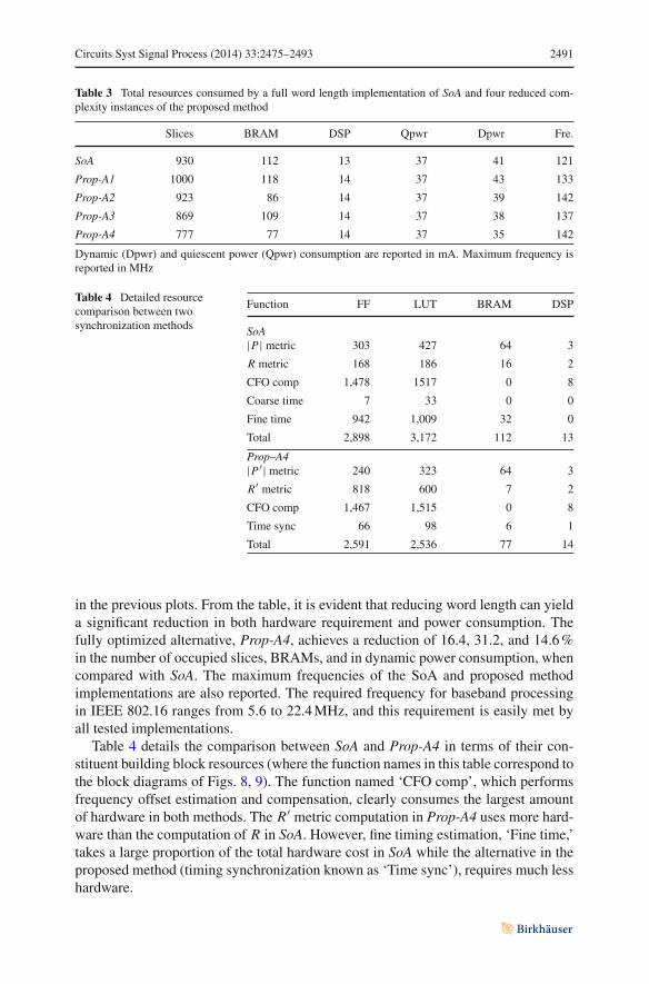
Table 3 Total resources consumed by a full word length implementation of SoA and four reduced com-plexity instances of the proposed method
Slices BRAM DSP Qpwr Dpwr Fre.
SoA 930 112 13 37 41 121
Prop-A1 1000 118 14 37 43 133
Prop-A2 923 86 14 37 39 142
Prop-A3 869 109 14 37 38 137
Prop-A4 777 77 14 37 35 142
Dynamic (Dpwr) and quiescent power (Qpwr) consumption are reported in mA. Maximum frequency isreported in MHz
Table 4 Detailed resourcecomparison between twosynchronization methods
Function FF LUT BRAM DSP
SoA|P| metric 303 427 64 3
R metric 168 186 16 2
CFO comp 1,478 1517 0 8
Coarse time 7 33 0 0
Fine time 942 1,009 32 0
Total 2,898 3,172 112 13
Prop–A4|P ′| metric 240 323 64 3
R′ metric 818 600 7 2
CFO comp 1,467 1,515 0 8
Time sync 66 98 6 1
Total 2,591 2,536 77 14
in the previous plots. From the table, it is evident that reducing word length can yielda significant reduction in both hardware requirement and power consumption. Thefully optimized alternative, Prop-A4, achieves a reduction of 16.4, 31.2, and 14.6 %in the number of occupied slices, BRAMs, and in dynamic power consumption, whencompared with SoA. The maximum frequencies of the SoA and proposed methodimplementations are also reported. The required frequency for baseband processingin IEEE 802.16 ranges from 5.6 to 22.4 MHz, and this requirement is easily met byall tested implementations.
Table 4 details the comparison between SoA and Prop-A4 in terms of their con-stituent building block resources (where the function names in this table correspond tothe block diagrams of Figs. 8, 9). The function named ‘CFO comp’, which performsfrequency offset estimation and compensation, clearly consumes the largest amountof hardware in both methods. The R′ metric computation in Prop-A4 uses more hard-ware than the computation of R in SoA. However, fine timing estimation, ‘Fine time,’takes a large proportion of the total hardware cost in SoA while the alternative in theproposed method (timing synchronization known as ‘Time sync’), requires much lesshardware.
2492 Circuits Syst Signal Process (2014) 33:2475–2493
5 Conclusion
This paper has presented and evaluated a novel algorithm for OFDM synchronizationand discussed its implementation on FPGA, with particular relevance to low-powerdevices. The proposed method is designed to improve CFO estimation accuracy and tobe much more robust to large CFO than common implementations, yet to be suitablefor efficient hardware implementation. Simulations were performed in MATLAB toinvestigate the performance of three versions of the proposed method applied to theIEEE 802.16-2009 downlink preamble, which showed that the method compares verywell to the two existing approaches. Specifically, the STO estimation results of theproposed method demonstrate an improved accuracy and robustness to large CFOcompared with the conventional methods. Similarly, the CFO estimation ability of theproposed method achieves a significant improvement.
The proposed method and current state-of-the-art approaches were implementedon FPGA to evaluate and compare the hardware resources usage and power consump-tion. Several trade-offs were explored in terms of reduced computation word lengthand number of computations, with interesting results. As well as achieving excellentsynchronization performance, the proposed method saves resources compared withthe state-of-the art-system and achieves an overall power saving of 14.6 %.
References
1. B. Ai, Z.X. Yang, C.Y. Pan, J.H. Ge, Y. Wang, Z. Lu, On the synchronization techniques for wirelessOFDM systems. IEEE Trans. Broadcasting 52, 236–244 (2006)
2. K. Bang, N. Cho, J. Cho, H. Jun, K. Kim, H. Park, D. Hong, A coarse frequency offset estimation inan OFDM system using the concept of the coherence phase bandwidth. IEEE Trans. Commun. 49(8),1320–1324 (2001). doi:10.1109/26.939841
3. J. Dowle, S.H. Kuo, K. Mehrotra, I.V. McLoughlin, FPGA-based MIMO and space-time processingplatform. EURASIP J. Appl. Signal Process. Special issue on MIMO implementation 34653, 1–14(2006)
4. V. Erceg, K.V.S. Hari, M.S. Smith, D.S. Baum, Channel models for fixed wireless applications. Tech-nical Report. IEEE802.16a-03/01 (2003)
5. J. Guffey, A. Wyglinski, G. Minden, Agile radio implementation of OFDM physical layer for dynamicspectrum access research. In IEEE Global Telecommunications Conference (GLOBECOM), pp. 4051–4055 (2007). doi:10.1109/GLOCOM.2007.770
6. L. Hanzo, T. Keller, OFDM and MC-CDMA : A Primer. Wiley-IEEE Press (New York, 2006)7. Z. Huang, B. Li, M. Liu, A proposed timing synchronization method for 802.16e downlink. In Inter-
national Symposium on Intelligent Signal Processing and Communication Systems (ISPACS), pp. 1–4(2010). doi:10.1109/ISPACS.2010.5704625
8. IEEE std.802.16-2009: IEEE Standard for Local and Metropolitan Area Networks Part16: Air Interfacefor Fixed Broadband Wireless Access Systems
9. T.H Kim, I.C. Park, Low-power and high-accurate synchronization for IEEE 802.16d systems. IEEETrans. Very Large Scale Integration (VLSI) Syst. 16(12), 1620–1630 (2008). doi:10.1109/TVLSI.2008.2001567
10. C.N. Kishore, V.U. Reddy, A frame synchronization and frequency offset estimation algorithm forOFDM system and its analysis. EURASIP J. Wirel. Commun. Netw. 2006, 1–16 (2006)
11. L. Liu, T. Cheng, Q. Xiaoyu, Q. Jiahui, Research on implementation of OFDM burst acket transmissionon software radio platform of FPGA. In 11th International Conference on Advanced CommunicationTechnology (ICACT), pp. 646–650 (2009)
12. J. Lotze, S.A. Fahmy, J. Noguera, B. Ozgül, L. Doyle, R. Esser, Development framework for imple-menting fpga-based cognitive network nodes. In Proceedings of the IEEE Global CommunicationsConference (GLOBECOM) (2009)
Circuits Syst Signal Process (2014) 33:2475–2493 2493
13. F. Manavi, Y. Shayan, Implementation of OFDM modem for the physical layer of IEEE 802.11astandard based on Xilinx Virtex-II FPGA. In Vehicular Technology Conference, VTC 2004-Spring.IEEE 59th, vol. 3 (2004), pp. 1768–1772. doi:10.1109/VETECS.2004.1390560
14. McLoughlin, I.V.: Computer Architecture: An Embedded Approach. McGraw-Hill, New York City(2011)
15. J. Park, T. Ogunfunmi, Efficient FPGA-based implementations of MIMO-OFDM physical layer. Cir-cuits Syst. Signal Process. 31(4), 1487–1511 (2012). doi:10.1007/s00034-012-9411-4
16. T.H. Pham, S.A. Fahmy, I.V. McLoughlin, Low-power correlation for IEEE 802.16 OFDM synchro-nisation on FPGA. IEEE Trans. Very Large Scale Integr. (VLSI) Syst. 21(8), 1549–1553 (2013)
17. A. Recio, P. Athanas, Physical layer for spectrum-aware reconfigurable OFDM on an FPGA. In 13thEuromicro Conference on Digital System Design: Architectures, Methods and Tools (DSD) (2010), pp.321–327. doi:10.1109/DSD.2010.110
18. T. Schmidl, D. Cox, Robust frequency and timing synchronization for OFDM. IEEE Trans. Commun.45(12), 1613–1621 (1997). doi:10.1109/26.650240
19. L. Schwoerer, VLSI suitable synchronization algorithms and architecture for IEEE 802.11a physicallayer. In IEEE International Symposium on Circuits and Systems (ISCAS), vol. 5 (2002), pp. V721–V724. doi:10.1109/ISCAS.2002.1010805
20. P.D. Sutton, J. Lotze, H. Lahlou, S.A. Fahmy, K. Nolan, B. Özgül, T.W. Rondeau, J. Noguera, L.Doyle, Iris: an architecture for cognitive radio networking testbeds. IEEE Commun. Mag. 48(9), 114–122 (2010)
21. K. Wang, J. Singh, M. Faulkner, FPGA implementation of an OFDM-WLAN synchronizer. In SecondIEEE International Workshop on Electronic Design, Test and Applications (DELTA) (2004), pp. 89–94.doi:10.1109/DELTA.2004.10039
22. K.W. Yip, Y.C. Wu, T.S. Ng, Design of multiplierless correlators for timing synchronization in IEEE802.11a wireless LANs. IEEE Trans. Consum. Electron. 49(1), 107–114 (2003). doi:10.1109/TCE.2003.1205462