Clifford Geetze (August 23, 1926, San Francisco – October 30, 2006, Philadelphia)
Robotics: Science and Systems 2006Philadelphia, PA, USA, August 16-19, 2006
1
Design methodologies for central pattern generators:an application to crawling humanoids
Ludovic Righetti and Auke Jan IjspeertBiologically Inspired Robotics Group
School of Computer and Communication SciencesEcole Polytechnique Federale de Lausanne (EPFL) - Switzerland
Email: [email protected], [email protected]
Abstract— Systems of coupled nonlinear oscillators inspiredfrom animal central pattern generators (CPGs) are increasinglyused for the control of locomotion in robots, in particularfor online trajectory generation. Indeed, such systems presentinteresting characteristics like limit cycle behavior (i.e. stability),synchronization, and the possibility to be entrained and modu-lated by external signals. There are now good methodologies fordesigning systems that exhibit specific gaits, i.e. specific phaserelations between oscillators, however techniques to modulatethe shape of the rhythmic signals in a controlled way are stillmissing.
In this article, we present a method for shaping the signalsof an oscillatory system according to several criteria that arerelevant for locomotion control (but which could also be usefulfor other applications). These criteria include being able to adjustthe relative durations of ascending and descending phases in acycle, and to temporarily modulate the dynamics of one oscillatoraccording to the states of another one. The first criterion isimportant for locomotion in order to adjust the duration of swingand stance phases, while the second allows one to introduce signalshape variations to deal with proper inter-limb coordination.
We apply the method to the design of a system of coupledoscillators used to control crawling in a simulated humanoidrobot. Using some key characteristics of signal shapes extractedfrom recordings of baby crawling, we design the system toproduce stable trot-like crawling gaits. Insights from symmetrygroups’ theory are used to design the right phase lags. Theoscillators are designed such that the speed of locomotion canbe adjusted by varying the duration of the stance phase whilekeeping the duration of the swing phase constant, like in mosttetrapod animals.
I. INTRODUCTION
This work is part of the RobotCub project, a 5-year Euro-pean project whose purpose is to build a 54-degrees of freedomhumanoid robot with the cognitive abilities of a child [1].The project has two main goals: first, to create an open andfreely-available humanoid platform for research in embodiedcognition, and second, to study cognitive development. Like toa child, the robot (called the iCub) should be able to exploreits environment by crawling and sitting to manipulate objects.
This contribution presents a design methodology for thecrawling controller, based on the Central Pattern Generator(CPG) paradigm. CPGs are neural networks located in thespine of vertebrates and are able to automatically generatethe control signals for the coordination of the muscles duringperiodic movements (e.g. locomotion, respiration) [2], [3].Although CPGs are controlled by simple descending paths
from higher parts of the brain, they are able to generate thesignals that control the complex coordination of the musclesduring rhythmic movement. CPGs are oscillatory networksthat can be modeled as coupled oscillators [4], [5]. Modelsof CPGs for robotics applications have proven successful,especially for locomotion control where they are used togenerate joint trajectories [6]–[8]. Their advantage is that itis easy to modulate the trajectories for locomotion and theyhave stability properties that makes them suitable for addingfeedback pathways. However, very few design methodologiesare currently available to construct them [9], [10]. In particular,techniques to modulate the shape of the rhythmic signals in acontrolled way are still missing.
Our design methodology follows a biologically inspired ap-proach. Indeed, to design the controller we study the crawlingbehavior of infants in order to extract important principlesfor our controller. Then we present a mathematical model ofCPG based on coupled nonlinear oscillators to reproduce thecrawling gait of infants. The originality of the model residesboth in the design of the oscillator and in the design of thecoupling scheme of the CPG. Note that while we design a CPGfor a specific task, we develop tools that are general enoughto be used in other applications.
We designed our oscillator from the observation that thegait pattern of animals and humans can be separated into twodistinct phases for each limb. The stance phase is the phaseduring which the limb touches the ground. The swing phaseis the phase during which the limb lifts off the ground. It isa well-known fact that when quadrupeds change their speedof locomotion, they might change their gait and the durationof the stance phase, but the duration of the swing phase tendsto remain the same [11]. However, most of the CPG modelsbased on coupled oscillators are not able to separate the swingand stance phases durations. In this contribution, we presentan oscillator model in which we can independently control theduration of each of these phases. This is an important feature,since during the swing phase, one limb is off the ground,thus making the system less stable and more dependent ondynamical properties of the controlled robot. So it seemsimportant to control independently the duration of both phases.
Furthermore, we present a coupling scheme based on theanalysis of the crawling pattern of real infants to reproducea similar gait. This coupling is based on the fact that the

PSfrag replacementsElbow joint
Shoulder joint
Hip joint
Knee joint
Fig. 1. Schematic of the joint angle we measured. We look at the movementof the limbs in the sagittal plane.
infants have a trot-like gait for the temporal synchronizationof the limbs but the stance and swing phases durations arevery different compared to most trotting animals. Moreover, itappears that there exists a correlation between the movementof a limb during its stance phase and the swing phase of theopposite limb. We reproduce this influence in the couplingscheme we present and we use the theory of symmetricdynamical systems [12]–[14] to infer the architecture of thenetwork of coupled oscillators. The validation of the design isdone by testing the CPG controller with a physics simulationof the iCub, since the real robot is still under construction.
In the next section, we first review data on crawling ininfants (Section II). We then present the design approachbehind our model of coupled oscillators (Section III). Thedesign is done incrementally with first the construction ofa nonlinear oscillator with two controlled time scales, thenthe addition of inter-limb influences between oscillators ofopposite limbs, and finally the addition of inter-limb couplingsbetween the complete four-oscillator system for implementingthe trot-like crawling gait. The model is tested with a rigidarticulated body simulation of the iCub, and compared tothe original infant crawling gaits (Section IV). The paperconcludes with a short discussion (Section V).
II. CRAWLING IN INFANTS
Very few studies about crawling in babies have been made.Some psychological studies about the development of crawlingin infants are available [15], [16] but they all focus on thecognitive development of infants through locomotion and nonehave focused on the kinematic details of crawling babies.
Babies can have various types of crawling and in thiscontribution we only focused on the standard gait [15]. Indeed,this gait is the most widespread one among infants and for afirst study of crawling it seemed to be the most appropriate.This gait corresponds to the locomotion of the baby on itshands and knees, with the phase relation of a trot. Moreinformation about the different types of crawling can be foundin [15].
In order to study crawling in infants, we used recordingsof the trajectories of the limbs of crawling babies. Theserecordings were made in the Department of Psychology atUppsala University, with a Qualisys Motion Capture System.These recordings where then converted into joint angle coor-dinates because this is a more natural coordinate frame forthe control of a robot. Figure 1 shows the basis for the joint
0 3 6
1.5
2
2.5
Time
Join
t Ang
le (
rad)
(a) Left Arm
0 3 6
1.5
2
2.5
Time
Join
t Ang
le (
rad)
(b) Right Arm
0 3 6
1.5
2
2.5
Time
Join
t Ang
le (
rad)
(c) Left Leg
0 3 6
1.5
2
2.5
Time
Join
t Ang
le (
rad)
(d) Right Leg
Fig. 2. Typical evolution of the joint angles of a baby during crawling. Thisis a reconstruction of a crawling sequence from the recordings of a crawlingbaby. We plot the joint angles (in radian) of the 4 limbs. For each limb, weplot the joint angles as defined in Figure 1. Hip and shoulder joints are plottedin plain line, the knee and elbow joints are in dashed line. The vertical linesdelimit the swing and stance phases, the swing phase being the shortest one.
angles and Figure 2 shows a typical crawling gait we got fromthe recordings. In this study we only focus on the joint anglesin the sagittal plane.
The first general remark we can state from these data is thatstandard crawling is a trot-like gait for its temporal relationsbetween limbs. It means that the diagonal limbs (e.g. left armand right leg) are in phase and half a period out of phase withthe opposite limbs. However, this trot-like gait is very differentfrom trot gaits found in animals. Generally, the trot gait is amedium speed gait between walk and gallop and the durationof the stance phase is quite short compared to the swingphase. The baby crawling gait has different properties in termsof these relative durations. Indeed, the stance phase is reallylong compared to the swing phase, it represents about 70% ofa whole cycle. A comparative study between the kinematicsof crawling babies and monkeys can be found in [17] andsupports these remarks about the crawling gait and the relativedurations of the swing and stance phases.
When looking at the movement of the hip and shoulderjoints (as defined in Figure 1), we notice that during the stancephase the joint slows down or even sometimes stops duringthe swing phase of the opposite limb. It is as if the swingphase of a limb was inhibiting the movement of the oppositelimb. This observation is also supported by the data shown in[17], although this fact is not mentioned by the authors.
The knee joint of each limb is folding in order to follow

the movement of the hip. Since the baby is crawling on itsknees, the exact control of this joint is less important (i.e. thetibia tends to simply rest on the ground). The elbow joints arefolding during the swing phase, to allow the arm to reach afurther region in front of the baby but do not move significantlyduring the stance phase.
Our goal here is not to study in detail the crawling sequenceof the baby, but to extract the features that seem important inorder to reproduce the same gait in a robot. The main featureswe would like to emphasize from these observations and fromthe study of [17] are first that the crawling gait is a trot-likegait in terms of phase relations between the limbs but with astance phase that is much longer than the swing phase contraryto usual trot gaits. Second, there is a correlation between theswing phase of a limb and the arrest of movement of the hip(or shoulder) joint of the opposite limb. Third, the elbow isfolding to allow the arm to do the swing phase.
III. MODEL
In this section we construct a model of CPG by meansof coupled oscillators. The CPG will be used to generate thecrawling trajectories for the iCub humanoid robot. To constructa CPG model, we define a number of features we would likeour model to have.
From biology, we know that during locomotion at variousspeeds, the duration of the swing phase of animals is alwaysconstant. Only the duration of the stance phase (and the changeof gait) influence the speed of locomotion [3], [11]. Thus, wewould like to be able to control independently the durationof each of these phases in the CPG. From the observationsof the previous section, we would like our CPG to generate atrot-like gait, with inhibition of the movement of the hip andshoulder joints during the swing phase of the opposite limbs.
From a robotics point of view, the CPG must haveproperties that makes it suitable for the control of a realrobot. We therefore want the CPG to show limit cycle behaviorand to be stable against perturbations, to allow for furtherintegration of sensory feedback. We also want to be ableto smoothly modulate the generated trajectory in frequencyand in amplitude to have a larger range of possible locomotion.
In summary our CPG must have the following properties
• Smooth modulation of the generated trajectory in fre-quency and amplitude
• Independent control of the duration of the swing andstance phases (the ascending and descending phases)
• Trot-like gait with a stance phase much longer than theswing phase
• Inhibition of the movement of the hip and shoulder jointsduring the swing phase of the opposite limbs
• Stability to perturbations to allow feedback integration
A. Two time-scale oscillator
We first present a model of a stable oscillator with thepossibility to control independently the duration of the swingand stance phases and the amplitude of the oscillations.
If we take a simple spring-like oscillatory system, theequation of motion of the joint angle can be expressed as
x = y (1)
y = −Kx (2)
The frequency of oscillations will be√
K and we will haveharmonic oscillations whose amplitude will depend on theinitial conditions of the system.
We want a duration of the stance phase different from theduration of the swing phase, thus we can think of an oscillatorchanging its spring constant according to the phase. It willhave a kstance spring constant during stance phase and kspring
constant during swing phase. The oscillator will switch amongthese two constants according to the phase, that is accordingto the sign of the velocity y of the system. We can thus writea general spring constant as
K = kstance + (kswing − kstance)1
eby + 1(3)
where the exponential function works as a step function whichselects either kswing or kstance according to the sign of thevelocity of movement y, b controls the speed of the switch.
Now we have a system that oscillates with different speedsaccording to the direction of the oscillations. Therefore wecan independently control the duration of the swing and thestance phases.
The problem with such an oscillatory system is that no limitcycle exists. There exist infinitely many periodic orbits aroundthe unstable center 0 and thus the system is not stable. We canpoint the flow toward one periodic orbit by constraining thetotal energy of the system, since it defines the maximum valuex can take in a spring system. The total energy of the systemis defined by
E =1
2(Kx2 + y2) (4)
which is the sum of the potential and kinetic energies of thesystem (we take the mass equal to one). At y = 0 we have
E = 12Kx2, which gives xmax = ±
√
2EK
. We can choose atotal energy such that xmax is bounded to a certain value,E = µ2K
2 and xmax = ±µ.
In order to constraint the amplitude of oscillations, we adda damping term to the preceding equation which bounds thetotal energy of the system. We then rewrite the whole systemas
x = y (5)
y = αy(µ2K − (Kx2 + y2)) − Kx (6)
where α is a constant controlling the speed of convergenceof the energy of the system 1
2 (Kx2 + y2) to the wanted totalenergy 1
2µ2K.The stability of the system can be seen if we set E =
12 (Kx2 + y2), then differentiation with respect to time gives
E =1
2Kx2 + αy2(Kµ2 − E) (7)
−1
1
X
0 1.5 3
0
20
−20
Time
Y
(a) kstance = kswing
−2
0
2
X
0 1.5 3
0
20
−40
Time
Y(b) kstance = 1
3kswing
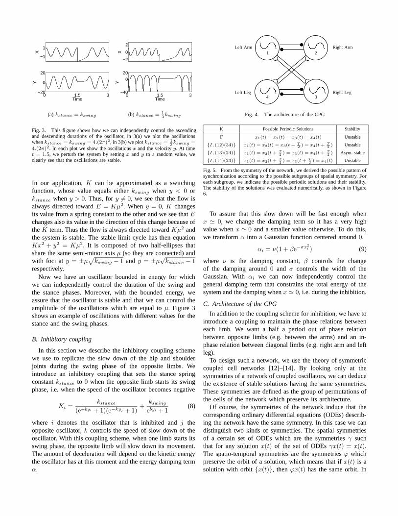
Fig. 3. This figure shows how we can independently control the ascendingand descending durations of the oscillator, in 3(a) we plot the oscillationswhen kstance = kswing = 4.(2π)2, in 3(b) we plot kstance = 1
3kswing =
4.(2π)2. In each plot we show the oscillations x and the velocity y. At timet = 1.5, we perturb the system by setting x and y to a random value, weclearly see that the oscillations are stable.
In our application, K can be approximated as a switchingfunction, whose value equals either kswing when y < 0 orkstance when y > 0. Thus, for y 6= 0, we see that the flow isalways directed toward E = Kµ2. When y = 0, K changesits value from a spring constant to the other and we see that Echanges also its value in the direction of this change because ofthe K term. Thus the flow is always directed toward Kµ2 andthe system is stable. The stable limit cycle has then equationKx2 + y2 = Kµ2. It is composed of two half-ellipses thatshare the same semi-minor axis µ (so they are connected) andwith foci at y = ±µ
√
kswing − 1 and y = ±µ√
kstance − 1respectively.
Now we have an oscillator bounded in energy for whichwe can independently control the duration of the swing andthe stance phases. Moreover, with the bounded energy, weassure that the oscillator is stable and that we can control theamplitude of the oscillations which are equal to µ. Figure 3shows an example of oscillations with different values for thestance and the swing phases.
B. Inhibitory coupling
In this section we describe the inhibitory coupling schemewe use to replicate the slow down of the hip and shoulderjoints during the swing phase of the opposite limbs. Weintroduce an inhibitory coupling that sets the stance springconstant kstance to 0 when the opposite limb starts its swingphase, i.e. when the speed of the oscillator becomes negative
Ki =kstance
(e−byi + 1)(e−kyj + 1)+
kswing
ebyi + 1(8)
where i denotes the oscillator that is inhibited and j theopposite oscillator, k controls the speed of slow down of theoscillator. With this coupling scheme, when one limb starts itsswing phase, the opposite limb will slow down its movement.The amount of deceleration will depend on the kinetic energythe oscillator has at this moment and the energy damping termα.
PSfrag replacements
1 2
34
Right Arm
Right LegLeft Leg
Left Arm
Fig. 4. The architecture of the CPG
K Possible Periodic Solutions Stability
Γ x1(t) = x2(t) = x3(t) = x4(t) Unstable
{I, (12)(34)} x1(t) = x2(t) = x3(t + T2 ) = x4(t + T
2 ) Unstable
{I, (13)(24)} x1(t) = x2(t + T2 ) = x3(t) = x4(t + T
2 ) Asym. stable
{I, (14)(23)} x1(t) = x2(t + T2 ) = x3(t + T
2 ) = x4(t) Unstable
Fig. 5. From the symmetry of the network, we derived the possible pattern ofsynchronization according to the possible subgroups of spatial symmetry. Foreach subgroup, we indicate the possible periodic solutions and their stability.The stability of the solutions was evaluated numerically, as shown in Figure6.
To assure that this slow down will be fast enough whenx ' 0, we change the damping term so it has a very highvalue when x ' 0 and a smaller value otherwise. To do this,we transform α into a Gaussian function centered around 0.
αi = ν(1 + βe−σx2i ) (9)
where ν is the damping constant, β controls the changeof the damping around 0 and σ controls the width of theGaussian. With αi we can now independently control thegeneral damping term that constrains the total energy of thesystem and the damping when x ' 0, i.e. during the inhibition.
C. Architecture of the CPG
In addition to the coupling scheme for inhibition, we have tointroduce a coupling to maintain the phase relations betweeneach limb. We want a half a period out of phase relationbetween opposite limbs (e.g. between the arms) and an in-phase relation between diagonal limbs (e.g. right arm and leftleg).
To design such a network, we use the theory of symmetriccoupled cell networks [12]–[14]. By looking only at thesymmetries of a network of coupled oscillators, we can deducethe existence of stable solutions having the same symmetries.These symmetries are defined as the group of permutations ofthe cells of the network which preserve its architecture.
Of course, the symmetries of the network induce that thecorresponding ordinary differential equations (ODEs) describ-ing the network have the same symmetry. In this case we candistinguish two kinds of symmetries. The spatial symmetriesof a certain set of ODEs which are the symmetries γ suchthat for any solution x(t) of the set of ODEs γx(t) = x(t).The spatio-temporal symmetries are the symmetries ϕ whichpreserve the orbit of a solution, which means that if x(t) is asolution with orbit {x(t)}, then ϕx(t) has the same orbit. In

0 10 20 30
x1
x2
x3
x4
Time
(a) Γ symmetry
0 10 20 30
x1
x2
x3
x4
Time
(b) {I, (12)(34)} symmetry
0 10 20 30
x1
x2
x3
x4
Time
(c) {I, (13)(24)} symmetry
0 10 20 30
x1
x2
x3
x4
Time
(d) {I, (14)(23)} symmetry
Fig. 6. We show the 4 possible patterns of synchrony we predicted fromthe symmetries of the network. We also show their stability properties byperturbing the oscillators. For patterns of Figs. 6(a) and 6(b) at time t = 10swe add a perturbation of 0.01 to x1, we see that such a small perturbationcompletely destroys the patterns and the crawling pattern appears. For thepattern of Figure 6(c), which is the crawling pattern, at time t = 10 we add1.0 to x1 and at time t = 20 we set the state variables of each oscillatorat a random value between [−2, 2], it is clear that this pattern is stable. Thepattern in Figure 6(d) is a pace gait, at time t = 10s we add a random noisebetween [−0.2, 0.2] on each xi. For all the experiment, we set kswing =kstance = π2, c1 = c2 = 1.0, β = 100, σ = 10, ν = 0.45, b = k = 100and µ = 1.
other word, if x(t) is a periodic solution, then ϕx(t) will bethe same solution with some phase shift.
For the crawling gait, if we number the limbs as in Figure4, we want the permutation of the diagonal limbs (13)(24) tobe a spatial symmetry and ((12)(34), 1
2 ) and ((14)(23), 12 ) to
be spatio-temporal symmetries with half a period phase shift.
We can construct a coupled cell network that is symmetricunder the group generated by these symmetries. By the H/Ktheorem, we know that the crawling gait is a periodic solutionof any network having the same symmetries.
Theorem 1: H/K Theorem [14] Let Γ be the symmetrygroup of a coupled cell network in which all cells are cou-pled and the internal dynamics of each cell is at least two-dimensional. Let K ⊂ H ⊂ Γ be a pair of subgroups. Thenthere exist periodic solutions to some coupled cell systemswith spatio-temporal symmetries H and spatial symmetries Kif and only if H/K is cyclic and K is an isotropy subgroup.Moreover, the system can be chosen so that the periodicsolution is asymptotically stable.
In our case, we have
Γ = H ={
I,(
(13)(24), 0)
,(
(12)(34),1
2
)
,(
(14)(23),1
2
)}
andK =
{
I,(
(13)(24), 0)}
We clearly see that H/K ∼= Z2 is cyclic and thus the trot-likegait exists as a solution of the system as long as we choose acoupling scheme such that K is an isotropy subgroup (whichis easy).
We just have to choose a coupling such that the trot gaitis stable, but we already know that it is possible. Since wehave inhibitory coupling between opposite limbs, we addstandard subtractive coupling between these oscillators inorder to enforce the half a period phase shift. As we alsowant in-phase relations between diagonal limbs, we also addadditive coupling between opposite limbs. These couplings arewell studied and we know that they make the desired phaseshifts between 2 oscillators stable [18]. Figure 4 shows thearchitecture of the network with the coupling scheme.
The general equations of the CPG that generates the trajec-tories for the hip and shoulder joints are then
xi = yi (10)
yi = αiyi(Ki(µ2 − x2
i ) − y2i ) − Kixi − c1yj + c2yk
(11)
Ki =kstance
(e−byi + 1)(e−kyj + 1)+
kswing
ebyi + 1(12)
αi = ν(1 + βe−σx2i ) (13)
where i = 1...4 denotes the ith oscillator, j the oppositeoscillator and k the diagonal oscillator, c1 and c2 are positivecoupling constants. We can verify that K is an isotropysubgroup for this set of equations.
Another advantage of this method to design the architectureof the CPG is that we can directly calculate the existence ofother patterns of oscillations by simply calculating the othersubgroups of Γ as is shown in Figure 5. It is very importantto be able to calculate the possible patterns of oscillations andto investigate their stability properties in order to be able toguarantee the behavior of our controller when adding feedbackloops. This method transforms the analytic problems of findingthese modes of oscillations into an algebraic one, which iseasier.
We see that there exist three other oscillatory regimesand we evaluated numerically the stability of each of thesepatterns, as can be seen in Figure 6. We note that the onlystable pattern of oscillation with a wide basin of attraction isthe trot gait. The pace gait has a small region of stability thatis limited and for a random noise between [−0.2, 0.2], thispattern disappears. The two other patterns are unstable. Afterthe perturbations, all these patterns converge to the trot gait.
Now we have a CPG that can generate the trajectoriesfor the hip and shoulder angles. This CPG is stable againstperturbations. We can also smoothly modulate the frequencyof the pattern by changing independently the frequency of the

0 10 20 30
x1
x2
x3
x4
Time
(a) Modulation of the frequency
0 10 20 30
x1
x2
x3
x4
Time
(b) Modulation of the amplitude
Fig. 7. In Figure 7(a) we modulate the frequency of the CPG. Initially wehave kswing = kstance = π2, at t = 10 we set kswing = 4kstance =4π2, which corresponds to a doubling of the speed of the swing and at t = 20we set kstance = 4kswing = 4π2. In Figure 7(b) we modulate the amplitudeof the pattern, we set µ = 1 at t = 0, then µ = 0.5 at t = 10 and µ = 1.5at t = 20. Note that an abrupt change in the control parameters (ki, µ) leadsto a smooth transition in the generated pattern.
0 3 6
1.5
2
2.5
Time
Left
Arm
0 3 6
1.5
2
2.5
Time
Rig
ht A
rm
0 3 6
1.5
2
2.5
Time
Left
Hip
0 3 6
1.5
2
2.5
Time
Rig
ht H
ip
Fig. 8. Comparison of the real trajectories of the hip and shoulder joints andthe trajectories generated by the CPG. The trajectories of the CPG are onlyshifted to oscillate around the same mean values as the real trajectories. Wesee that the trajectories generated by our model fit quite well the real ones,especially for the right limbs.
ascending and descending oscillations. A smooth modulationof the amplitude is straightforward by changing the parameterµ. Examples of such modulations can be seen in Figure 7.
IV. VALIDATION OF THE MODEL
A. Comparison with the real baby
In this section we compare the trajectories of the shoulderand hip joints of a baby with the ones generated by the CPG.In Figure 8 we see the result of the comparison. The theoreticaltrajectories match quite well the experimental ones. This resultshows that the CPG can reproduce the main features ofcrawling and therefore it supports our design methodology.
√kstance
√kswing
2 4 6
5
10
15
20
0.1
0.2
0.3
Fig. 9. Characterization of the speed of the simulated iCub according tothe duration of the stance and swing phases. The left color bar shows thecorrespondence between the colors and the speed (in m · s−1).
B. Crawling on the simulated robot
In this section we show experiments where we use our CPGto control a crawling simulated robot. The simulation is donewith Webots [19], a simulator based on ODE [20], an opensource physics engine for simulating 3D rigid body dynamics.The simulation is as close as possible to the robot currentlyunder construction. This means that we use the correct lengthsand mass distributions for each limbs.
The CPG we developed generates the trajectories for thehip and shoulder joints, so we use these trajectories to controlthe position of the hip and shoulder joints. However, we sawin Section II that the elbow was also used during the swingphase of the corresponding arm. The elbow is folding duringthe swing phase, allowing the arm to reach the region in frontof the baby.
We thus set the angle of the elbow joint according to thephase of the arm, that is, according to the sign of y. Theangle of the elbow, θi, will follow a Gaussian movementcorresponding to
θi = γe−(yi−
√kswing)2
τ (14)
where i corresponds to the left or right arm, γ is the amplitudeof the movement and τ is the width of the Gaussian. TheGaussian is centered on −
√
kswing which corresponds to themaximum speed of the shoulder during the swing phase. Theoscillator reaches this value at x ' 0. The elbow will thenfold during the swing phase, following a Gaussian movementand will not move during the stance phase. We also controlthe DOF of the arm, which is orthogonal to the sagittal plane,in the same way. This allows the hand to have more heightduring the swing phase. Figure 10 shows a crawling sequenceof the simulated robot and of a real baby.
We also investigated the importance of the kswing andkstance constants for the speed of locomotion of the robot.

Fig. 10. We show a sequence of crawling of both a real baby and the simulated robot. There is an interval of 120ms between each picture.
The result of this experiment can be seen in Figure 9. We seein this figure that the simulated robot could crawl up to 0.3m · s−1. A baby crawls around 0.18 m · s−1 [17], so the robotcan attain the speed of a real baby. In this figure, we see thatincreasing kstance increases the speed of the robot. However,we see that beyond a certain value the speed of locomotionbecomes really small, which corresponds to cases where therobot falls. We also note that increasing kswing for a givenkstance does not lead to a significantly faster crawling. Thisseems normal since the swing phase is not the longer part ofthe movement. However the value of kswing is important forthe stability of locomotion, a too slow swing phase leads tocases where the robot falls or the swinging arm touches theground too early, in the middle of the swing phase.
V. CONCLUSION
In this contribution, we presented an oscillator in which wecan independently control the duration of the ascendant anddescendant phases. In locomotion control it enables us to setthe duration of the swing and the stance phases separately.
We also presented an original way of coupling two oscilla-tors, in order to reproduce the inhibited movement of a limbduring the swing phase of the opposite limb. Moreover, weshowed that we can use the theory of symmetric coupledcells to construct the architecture of a network of coupledoscillators, given a desired symmetry in the oscillations. Thisalso allowed us to derive the other patterns of oscillations ournetwork could support in a very simple manner, transformingthe analytic problem into an algebraic one. The CPG weconstructed has several properties that are relevant to robotics:it is stable against perturbations, which is good for sensoryfeedback integration, and we can easily modulate the patternin frequency and amplitude.
Finally we showed that our model of CPG matched quitewell the experimental data of crawling babies and we showedthat it could be successfully used to control a simulatedhumanoid robot.
The oscillator we constructed and the design methodologywe followed to build the network of coupled oscillators aregeneral enough to be used in many other applications whererhythmic pattern generation is necessary.
Our future research goals will be to explore how we canintegrate sensory feedback to deal with unexpected perturba-tions and how we can also control the direction of locomotionwith this CPG. Finally we will test this controller on the realrobot, as soon as it is built.
ACKNOWLEDGMENT
We would like to gratefully acknowledge Kerstin Rosander,Ines Halberstadt and Heiko Backes from Uppsala University(Sweden) for providing the kinematic data of crawling babies.
This work was made possible thanks to the support ofthe European Commission’s Cognition Unit, project no. IST-2004-004370: RobotCub (L.R.) and to a grant from the SwissNational Science Foundation (A.I.).
REFERENCES
[1] G. Sandini, G. Metta, and D. Vernon, “Robotcub: an open frameworkfor research in embodied cognition,” 2004, paper presented at theIEEE-RAS/RJS International Conference on Humanoid Robotics, SantaMonica, CA.
[2] S. Grillner, “Neurobiological bases of rhythmic motor acts in verte-brates,” Science, vol. 228, no. 4696, pp. 143–149, 1985.
[3] G. N. Orlovsky, T. G. Deliagina, and S. Grillner, Neuronal control oflocomotion: from mollusc to man. Oxford University Press, 1999.
[4] J. Collins and S. Richmond, “Hard-wired central pattern generators forquadrupedal locomotion,” Biological Cybernetics, vol. 71, no. 5, pp.375–385, 1994.
[5] N. Kopell and G. Ermentrout, “Coupled oscillators and the design ofcentral pattern generators,” Mathematical Biosciences, vol. 90, no. 1–2,pp. 87–109, 1988.

[6] G. Endo, J. Nakanishi, J. Morimoto, and G. Cheng, “Experimentalstudies of a neural oscillator for biped locomotion with qrio,” inProceedings of the 2005 IEEE International Conference on Roboticsand Automation, Barcelona, Spain, 2005, pp. 598–604.
[7] H. Kimura, S. Akiyama, and K. Sakurama, “Realization of dynamicwalking and running of the quadruped using neural oscillators,” Au-tonomous Robots, vol. 7, no. 3, pp. 247–258, 1999.
[8] G. Taga, “Emergence of bipedal locomotion through entrainment amongthe neuro-musculo-skeletal system and the environment,” Physica D:Nonlinear Phenomena, vol. 75, no. 1–3, pp. 190–208, 1994.
[9] A. Ijspeert, J. Nakanishi, and S. Schaal, “Learning rhythmic move-ments by demonstration using nonlinear oscillators,” in Proceedingsof the IEEE/RSJ Int. Conference on Intelligent Robots and Systems(IROS2002), 2002, pp. 958–963.
[10] L. Righetti and A. Ijspeert, “Programmable central pattern generators:an application to biped locomotion,” in International Conference onRobotics and Automation (ICRA2006), 2006.
[11] T. A. McMahon, Muscles, Reflexes, and Locomotion. PrincetonUniversity Press, 1984.
[12] P. Buono and M. Golubitsky, “Models of central pattern generatorsfor quadruped locomotion. i. primary gaits.” Journal of MathematicalBiology, vol. 42, no. 4, pp. 291–326, 2001.
[13] M. Golubitsky and I. Stewart, The symmetry perspective: from equi-librium to chaos in phase space and physical space. Basel, Boston,Berlin: Birkhauser, 2002.
[14] ——, “Nonlinear dynamics of network: the groupoid formalism,” Bul-letin of the American Mathematical Society, vol. 43, pp. 305–364, 2006.
[15] K. E. Adolph, B. Vereijken, and M. A. Denny, “Learning to crawl,”Child Development, vol. 69, no. 5, pp. 1299–1312, October 1998.
[16] E. Goldfield, “Transition from rocking to crawling: postural constraintson infant movement,” Developmental Psychology, vol. 25, no. 6, pp.913–919, 1989.
[17] C. Niemitz, “Kinematics and ontogeny of locomotion in monkeys andhuman babies,” Zeitschrift fur Morphologie und Anthropologie, vol. 83,pp. 383–400, March 2002.
[18] A. Pikovsky, R. Rosenblum, and J. Kurths, Synchronization, A universalconcept in nonlinear sciences, ser. Cambridge Nonlinear Science Series.Cambridge University Press, Cambridge, UK, 2001, vol. 12.
[19] O. Michel, “Webots: Professional mobile robot simulation,” Interna-tional Journal of Advanced Robotic Systems, vol. 1, no. 1, pp. 39–42,2004.
[20] Open dynamic engine documentation. [Online]. Available:http://www.ode.org