ROBOTIC TECHNOLOGIES FOR A NON-STANDARD … · NON-STANDARD DESIGN AND CONSTRUCTION IN ARCHITECTURE...
92
ROBOTIC TECHNOLOGIES FOR A NON-STANDARD DESIGN AND CONSTRUCTION IN ARCHITECTURE Research project Ref: PTDC/ATP-AQI/5124/2012 REPORT Task 1.1.2 Survey: Robotic Technologies March 2014 Research Institutions: Support:
Transcript of ROBOTIC TECHNOLOGIES FOR A NON-STANDARD … · NON-STANDARD DESIGN AND CONSTRUCTION IN ARCHITECTURE...

ROBOTIC TECHNOLOGIES FOR A NON-STANDARD DESIGN AND CONSTRUCTION IN ARCHITECTURE Research project Ref: PTDC/ATP-AQI/5124/2012
REPORT Task 1.1.2 Survey: Robotic Technologies March 2014
Research Institutions: Support:
Institutions:FAUP - Faculdade de Arquitectura da Universidade do Porto (Promoter)CEAU - Centro de Estudos em Arquitectura e UrbanismoINESC TEC Porto
Sponsor:FCT - Fundação para a Ciência e a TecnologiaFunded by: This work is funded by FEDER Funds through the “Programa Operacional Factores de Competividade - COMPETE” and by National Funds through “FCT - Fundação para a Ciência e a Tecnologia” within the project PTDC/ATP - AQI/5124/2012 entitled “Robotic Technology for a Non-Standard project and construction in Architecture”.
Research Project Coordinator:Prof. Dr. José Pedro Sousa
Task Team:Coordination: António Paulo Moreira, Germano Veiga, José Pedro SousaTeam: Daniel Almeida, Joana Costa, Leonhard Trummer, Luís Ferreira, Manuel Oliveira, Nuno Maia, Pedro Martins and Pedro VarelaSupport: António Valente, Manuel Silva, P. B. de Moura Oliveira.
Period:July 2013 - March 2014
Note:This is the work produced in the scope of a Research Project without any commercial intentions. The purpose of this document is to register and monitorize the developed work.
2

Index
5 Summary
1. Robots7 Kuka Roboter GmbH9 ABB robotics11 Yaskawa Motoman Robotics13 FANUC15 Universal Robots
2. Tools and Accessories17 Spindle19 Gripper21 Rail track23 Rotating Table25 Custom end-effector
3. Applications in Architecture
3.1 Concrete27 Concrete Printing29 Contour Crafting31 [C]space Pavillion33 Diamond Wire Cutting Workshop35 Pinch Wall37 Pre: Vault39 Robotic Casting41 Tailorcrete43 The Perforated Wall 2
3.2 Ceramics / Bricks45 Brickfacade of Keller AG Headquarters47 Flight Assembled Archirecture49 Gantenbein Vineyard Facade51 Pike Loop53 Structural Oscillations55 The Programmed Column 2
3.3 Wood57 ICD/ITKE Research Pavillion 201059 ICD/ITKE Research Pavillion 201161 Robot Chainsaw Stool63 The Sequential Wall65 West est Pavillion
3.4 Metal67 Auto-Eclipsis69 Curved Folding71 Metal Sky73 Workshop Robotic Facade Fabrication
3.5 Styrofoam75 Automated FoamDome77 Hyperbody79 Robotic FOAMing81 Synthetic 2012
3.6 Stone83 MLK Jr. Park Stone Vault
3.7 Others85 ICD ITKE Research Pavillion 201287 Robotic Manipulation Carbon Fibres
4. Applications in other fields89 Delta Robot91 Dual-arm robot
3

4

T.1.2 Survey
Robotic Technologies
T.1.2 SURVEY Robotic Technologies Introduction In the scope of the introductory activities of the project (T1.1, T.1.2 and T1.3), the present task surveys the current state-of-the art in robotic technologies, and their application in the field of architecture. Evolving with the advances of the computer, the development of robotic technologies has spread across different kinds of industries, from the automotive to the pharmaceutical. In the architecture field, the use of robots started to be explored in the 70’s, with the goal of automating the repetitive tasks in the construction of high-rise buildings. The robotic system consisted in a big infrastructure made out of automated cranes, scaffoldings and other devices, occupying the whole construction site. Japan was at the center of this innovation, but the expectations were never fulfilled. The introduction of such robotic technologies required highly standardized building components and assembly processes to be efficient. As result, the creative possibilities in architecture turned out to be very narrow, and these processes came into disuse. In the beginning of the XXI century, Gramazio+Kohler started to explore at the ETH Zurich the use of robotic arms in the architectural construction. With a different vision, instead of being in the construction site, the robotic arm was used to pre-fabricate building parts. At the same time, depending on the end-effector (tool), the robot could perform different fabrication or assembly operations. This fact coupled with its freedom and precision of movements in space drew new conditions to materialize innovative forms and structures, employing different materials. Since then, this technology started to be explored by other architects and researchers, investing in the production of new end-effectors, in the programming of new robotic behaviors, or in finding new applications for the building industry. Its use as a 3D printing technology, and its application in the construction site are some of the current architectural challenges that are being pursued with these technologies. Structure Recognizing this state of the art, the current survey of robotic technologies was structured in the following four categories:
• Robots Provided with multiple rotational axis, the applications of a robotic arm are as endless as the number of tools and accessories attached to it. Unlike conventional CNC machines, each robot brand has its own code to control their robots, meaning that each one has its specific way to control the robot.
• Tools and accessories
The end-effector provides the robot a way to interact with the object. Regarding the fabrication of physical parts, there is a wide landscape of tools and accessories available in the market, while others can be developed for a specific purpose. The most popular end-effectors are the spindle, the gripper or the hot-wire. The most current sensors are dedicated to visual and pressure detection.
5

T.1.2 Survey
Robotic Technologies
• Applications in Architecture
Since Gramazio+Kohler, architects have used the robotic arm to perform different fabrication operations. Aligned with the structure of the research project, it was decided to divide the examples according to the employed materials, like: concrete, ceramics/brick, wood, metal, styrofoam, stone and others.
• Applications in other fields
The origins and developments of the robotic industry tend to occur outside the field of architecture. Thus, it is important to check what’s happening in other fields to find some inspiration for technology transfer and innovation in architecture.
Conclusion This research on Robotic Technologies demonstrates that the industrial robot is an object of research by itself. The main developments are focused in two main areas: the end-effector – to customize the application – and sensors – to set new types of behavior. In this context, a series of activities are planned to improve the capabilities of the team. Training and collaboration with other teams will assist not only the development of practical skills, but also the inspiration to innovate in the field. This is influent in the developments of tasks T2.1, T2.2, T3.1, T3.2 and T4.1.
6
T.1.2 Survey
Robotic Technologies
• Applications in Architecture
Since Gramazio+Kohler, architects have used the robotic arm to perform different fabrication operations. Aligned with the structure of the research project, it was decided to divide the examples according to the employed materials, like: concrete, ceramics/brick, wood, metal, styrofoam, stone and others.
• Applications in other fields
The origins and developments of the robotic industry tend to occur outside the field of architecture. Thus, it is important to check what’s happening in other fields to find some inspiration for technology transfer and innovation in architecture.
Conclusion This research on Robotic Technologies demonstrates that the industrial robot is an object of research by itself. The main developments are focused in two main areas: the end-effector – to customize the application – and sensors – to set new types of behavior. In this context, a series of activities are planned to improve the capabilities of the team. Training and collaboration with other teams will assist not only the development of practical skills, but also the inspiration to innovate in the field. This is influent in the developments of tasks T2.1, T2.2, T3.1, T3.2 and T4.1.
T.1.2 Survey
Robotic Technologies Robots
1
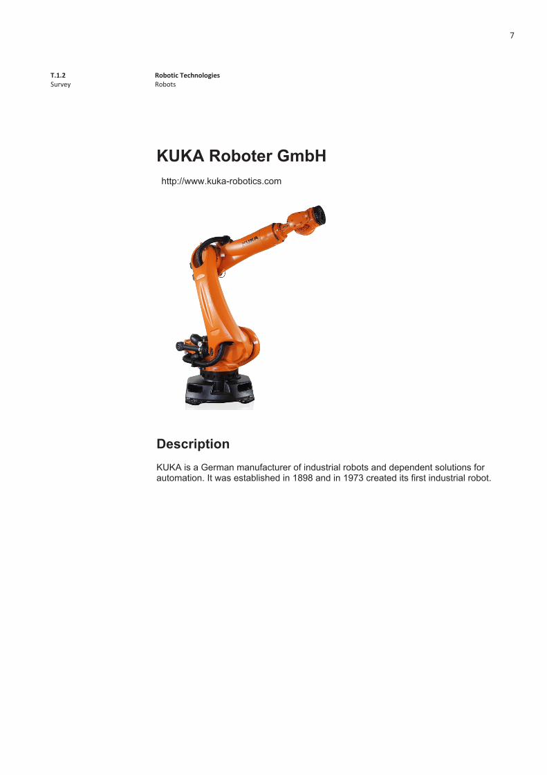
KUKA Roboter GmbH http://www.kuka-robotics.com
Description KUKA is a German manufacturer of industrial robots and dependent solutions for automation. It was established in 1898 and in 1973 created its first industrial robot.
7

8

T.1.2 Survey
Robotic Technologies Robots
1
ABB robotics http://new.abb.com/products/robotics
Description ABB is a leading supplier of industrial robots, modular manufacturing systems and service.
9

10

T.1.2 Survey
Robotic Technologies Robots
1
Yaskawa Motoman Robotics http://www.motoman.com/
Description The Yaskawa Electric is a Japanese manufacturer of servos, machine controllers, AC Motor drives, switches and robots, founded in 1915. Founded in 1989, Yaskawa Motoman robots are heavy duty industrial robots used for example in car manufacturing.
11

12

T.1.2 Survey
Robotic Technologies Robots
1
FANUC
http://www.fanucamerica.com/
Description FANUC had its origins as a part of Fujitsu, but became independent in 1972. Producing NC and servo systems, it is now a global player in robots production for multi-purposes.
13

14

T.1.2 Survey
Robotic Technologies Robots
1
Universal Robots http://www.universal-robots.com/
Description Industrial Robots was established in 2005 with the aim of reinventing the use of robots for the food industry. It was nevertheless applied for many other field. Its main advantages rely on low price, ease of use and safety. It has pressure sensors which make safety guards not necessary.
15

16

T.1.2 Survey
Robotic Technologies Robots
1
Spindle
Description The spindle is a tool which makes a force around a central axis. It is mainly used for milling and drilling, but it can also be used for finishing operations, such as deburring, brushing or filing.
Tools and Acessories
17

18

T.1.2 Survey
Robotic Technologies Robots
1
Gripper
Description A gripper may be used to pick objects. There are some variants which can grip an object by exerting parallel force, or by using three grips instead of two which gives the possibility of handling tubes.
Tools and Acessories
19

20

T.1.2 Survey
Robotic Technologies Robots
1
Rail track
Description Robot tracks expand the working envelope of the robot allowing it to reach further. These rail track are also used in walls or ceilings, liberating floor space for other uses.
Tools and Acessories
21

22
T.1.2 Survey
Robotic Technologies Robots
1
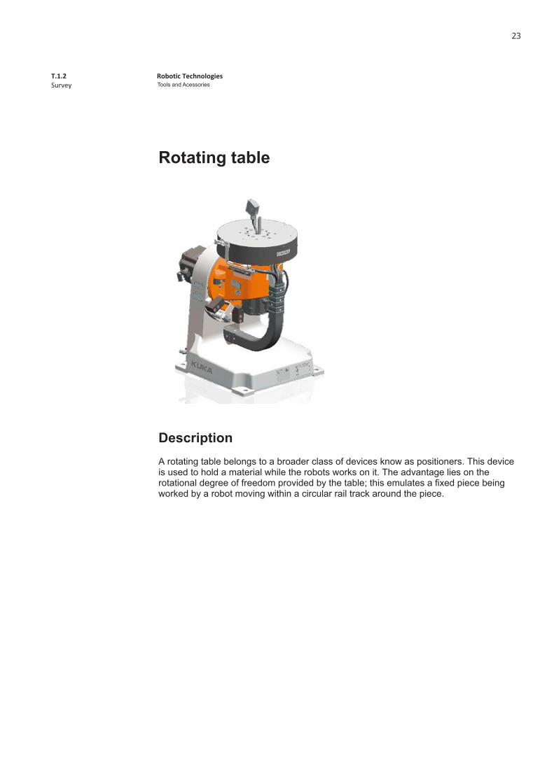
Rotating table
Description A rotating table belongs to a broader class of devices know as positioners. This device is used to hold a material while the robots works on it. The advantage lies on the rotational degree of freedom provided by the table; this emulates a fixed piece being worked by a robot moving within a circular rail track around the piece.
Tools and Acessories
23

24
T.1.2 Survey
Robotic Technologies Robots
1
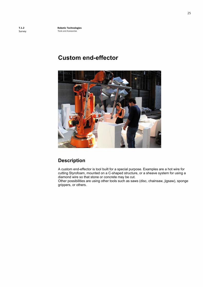
Custom end-effector
Description A custom end-effector is tool built for a special purpose. Examples are a hot wire for cutting Styrofoam, mounted on a C-shaped structure, or a sheave system for using a diamond wire so that stone or concrete may be cut. Other possibilities are using other tools such as saws (disc, chainsaw, jigsaw), sponge grippers, or others.
Tools and Acessories
25

26
T.1.2 Survey
Robotic Technologies Concrete
1
Concrete
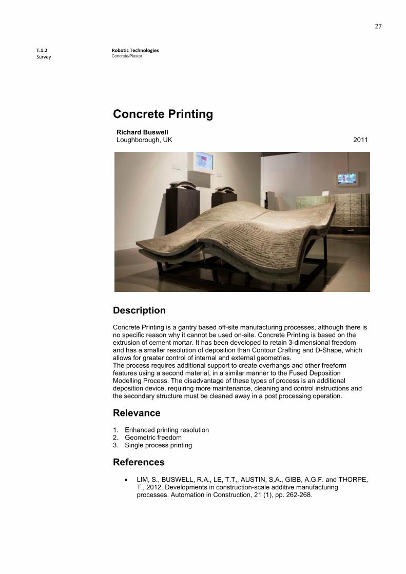
Concrete PrintingRichard Buswell Loughborough, UK 2011
DescriptionConcrete Printing is a gantry based off-site manufacturing processes, although there is no specific reason why it cannot be used on-site. Concrete Printing is based on the extrusion of cement mortar. It has been developed to retain 3-dimensional freedom and has a smaller resolution of deposition than Contour Crafting and D-Shape, which allows for greater control of internal and external geometries. The process requires additional support to create overhangs and other freeform features using a second material, in a similar manner to the Fused Deposition Modelling Process. The disadvantage of these types of process is an additional deposition device, requiring more maintenance, cleaning and control instructions and the secondary structure must be cleaned away in a post processing operation.
Relevance1. Enhanced printing resolution 2. Geometric freedom 3. Single process printing
References LIM, S., BUSWELL, R.A., LE, T.T,, AUSTIN, S.A., GIBB, A.G.F. and THORPE,
T., 2012. Developments in construction-scale additive manufacturing processes. Automation in Construction, 21 (1), pp. 262-268.
T.1.2 Survey
Robotic Technologies Concrete
1
Concrete
Concrete PrintingRichard Buswell Loughborough, UK 2011
DescriptionConcrete Printing is a gantry based off-site manufacturing processes, although there is no specific reason why it cannot be used on-site. Concrete Printing is based on the extrusion of cement mortar. It has been developed to retain 3-dimensional freedom and has a smaller resolution of deposition than Contour Crafting and D-Shape, which allows for greater control of internal and external geometries. The process requires additional support to create overhangs and other freeform features using a second material, in a similar manner to the Fused Deposition Modelling Process. The disadvantage of these types of process is an additional deposition device, requiring more maintenance, cleaning and control instructions and the secondary structure must be cleaned away in a post processing operation.
Relevance1. Enhanced printing resolution 2. Geometric freedom 3. Single process printing
References LIM, S., BUSWELL, R.A., LE, T.T,, AUSTIN, S.A., GIBB, A.G.F. and THORPE,
T., 2012. Developments in construction-scale additive manufacturing processes. Automation in Construction, 21 (1), pp. 262-268.
Concrete/Plaster
27

T.1.2 Survey
Robotic Technologies Concrete
2
Additional Images
1. Finished wall element 2. Wall element in production
3. Functional voids and reinforcement close-up 4. Non-optimal paths and optimal paths
5. Wall element plan
T.1.2 Survey
Robotic Technologies Concrete
2
Additional Images
1. Finished wall element 2. Wall element in production
3. Functional voids and reinforcement close-up 4. Non-optimal paths and optimal paths
5. Wall element plan
Concrete/Plaster
28
T.1.2 Survey
Robotic Technologies Concrete
1
Concrete
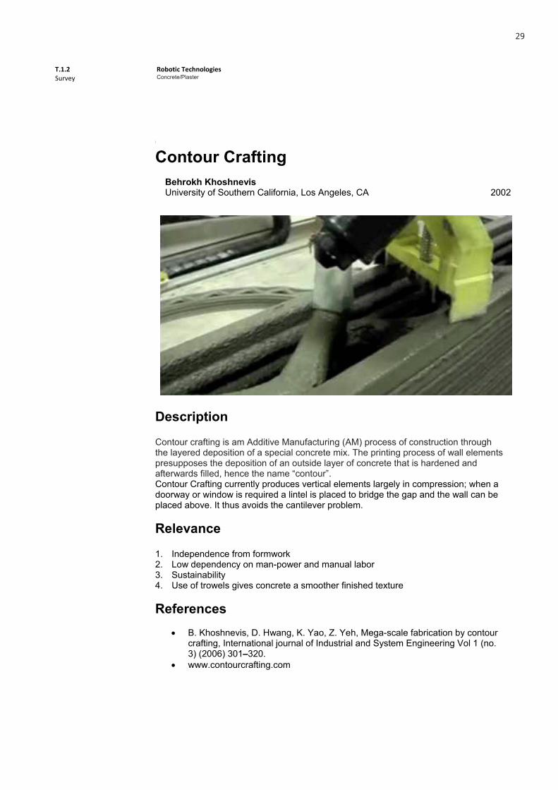
Contour CraftingBehrokh Khoshnevis University of Southern California, Los Angeles, CA 2002
Description
Contour crafting is am Additive Manufacturing (AM) process of construction through the layered deposition of a special concrete mix. The printing process of wall elements presupposes the deposition of an outside layer of concrete that is hardened and afterwards filled, hence the name “contour”. Contour Crafting currently produces vertical elements largely in compression; when a doorway or window is required a lintel is placed to bridge the gap and the wall can be placed above. It thus avoids the cantilever problem.
Relevance
1. Independence from formwork 2. Low dependency on man-power and manual labor 3. Sustainability 4. Use of trowels gives concrete a smoother finished texture
References B. Khoshnevis, D. Hwang, K. Yao, Z. Yeh, Mega-scale fabrication by contour
crafting, International journal of Industrial and System Engineering Vol 1 (no. 3) (2006) 301–320.
www.contourcrafting.com
T.1.2 Survey
Robotic Technologies Concrete
1
Concrete
Contour CraftingBehrokh Khoshnevis University of Southern California, Los Angeles, CA 2002
Description
Contour crafting is am Additive Manufacturing (AM) process of construction through the layered deposition of a special concrete mix. The printing process of wall elements presupposes the deposition of an outside layer of concrete that is hardened and afterwards filled, hence the name “contour”. Contour Crafting currently produces vertical elements largely in compression; when a doorway or window is required a lintel is placed to bridge the gap and the wall can be placed above. It thus avoids the cantilever problem.
Relevance
1. Independence from formwork 2. Low dependency on man-power and manual labor 3. Sustainability 4. Use of trowels gives concrete a smoother finished texture
References B. Khoshnevis, D. Hwang, K. Yao, Z. Yeh, Mega-scale fabrication by contour
crafting, International journal of Industrial and System Engineering Vol 1 (no. 3) (2006) 301–320.
www.contourcrafting.com
Concrete/Plaster
29

T.1.2 Survey
Robotic Technologies Concrete
2
Additional Images
1. Built wall element 2. Built wall element
3. Contour Crafting machine 4. Printing head diagram
5. Large scale process illustration
T.1.2 Survey
Robotic Technologies Concrete
2
Additional Images
1. Built wall element 2. Built wall element
3. Contour Crafting machine 4. Printing head diagram
5. Large scale process illustration
Concrete/Plaster
30

T.1.2 Survey
Robotic Technologies Concrete
1
Concrete
[C]space Pavillion Alan Dempsey; Alvin Huang Architectural Association School, London, UK 2008
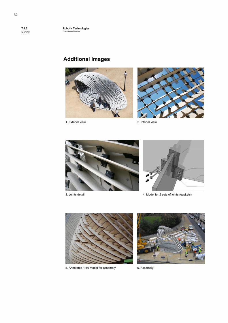
DescriptionThe pavilion is formed by a discontinuous shell structure spanning over 10m made of thin fibre reinforced concrete elements which perform as structure and skin, floor walls and furniture. The jointing of discrete concrete profiles exploits the tensile strength of Fibre-C and a simple intersecting notch joint, which is locked together using a bespoke rubber gasket assembly. The angle of intersection at each joint continuously varies across the structure. The entire design process was conducted using 3D digital and physical modeling, and the design development was completed using rigorous constraint modeling and scripting to control over 850 individually different profiles and 2000 joints. Finally, the elements were manufactured directly from digital models on CNC cutting equipment using standard sized 13mm thick flat sheets of Fibre-C concrete and 15mm thick mild steel plate.
Relevance1. Use of concrete in sheet form with CNC cutting 2. Structural optimization 3. Possibility for re-visitation with robotic technologies 4. Visual porosity
References
T.1.2 Survey
Robotic Technologies Concrete
1
Concrete
[C]space Pavillion Alan Dempsey; Alvin Huang Architectural Association School, London, UK 2008
DescriptionThe pavilion is formed by a discontinuous shell structure spanning over 10m made of thin fibre reinforced concrete elements which perform as structure and skin, floor walls and furniture. The jointing of discrete concrete profiles exploits the tensile strength of Fibre-C and a simple intersecting notch joint, which is locked together using a bespoke rubber gasket assembly. The angle of intersection at each joint continuously varies across the structure. The entire design process was conducted using 3D digital and physical modeling, and the design development was completed using rigorous constraint modeling and scripting to control over 850 individually different profiles and 2000 joints. Finally, the elements were manufactured directly from digital models on CNC cutting equipment using standard sized 13mm thick flat sheets of Fibre-C concrete and 15mm thick mild steel plate.
Relevance1. Use of concrete in sheet form with CNC cutting 2. Structural optimization 3. Possibility for re-visitation with robotic technologies 4. Visual porosity
References
Concrete/Plaster
31
T.1.2 Survey
Robotic Technologies Concrete
2
Additional Images
1. Exterior view 2. Interior view
3. Joints detail 4. Model for 2 sets of joints (gaskets)
5. Annotated 1:10 model for assembly 6. Assembly
T.1.2 Survey
Robotic Technologies Concrete
2
Additional Images
1. Exterior view 2. Interior view
3. Joints detail 4. Model for 2 sets of joints (gaskets)
5. Annotated 1:10 model for assembly 6. Assembly
Concrete/Plaster
32

T.1.2 Survey
Robotic Technologies Concrete
1
Concrete
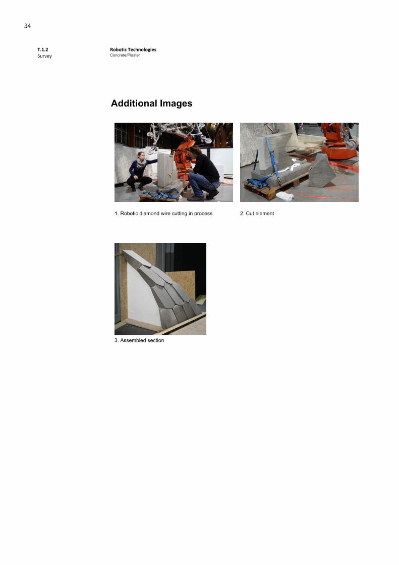
Diamond Wire Cutting WorkshopWes MacGee, Jelle Feringa & Lauren Vasey RobArch 2012, Graz, Austria 2012
Author DescriptionDiamond wire concrete cutting was one of two parallel workshops that took place at the RobArch 2012 Conferences and experimented with cutting concrete slabs with the help of a robotic arm equipped with a diamond wire as the other workshop studied the use of a robotic hotwire for the production of formwork for concrete elements. Around 10 elements were cut and assembled forming a section of a specific surface that was self-supported through compression and locked in place with custom interlocking edges.
RelevanceDiamond wire cutting of concrete is a somewhat technical process, used mainly for purposes not directly concerned with architecture. Although a slow process, it eliminates the need for formwork and proposes interesting opportunities for exploring non-regular joints and assemblies of concrete block elements.
References http://www.robarch2012.org http://amarkalo.blogspot.pt
T.1.2 Survey
Robotic Technologies Concrete
1
Concrete
Diamond Wire Cutting WorkshopWes MacGee, Jelle Feringa & Lauren Vasey RobArch 2012, Graz, Austria 2012
Author DescriptionDiamond wire concrete cutting was one of two parallel workshops that took place at the RobArch 2012 Conferences and experimented with cutting concrete slabs with the help of a robotic arm equipped with a diamond wire as the other workshop studied the use of a robotic hotwire for the production of formwork for concrete elements. Around 10 elements were cut and assembled forming a section of a specific surface that was self-supported through compression and locked in place with custom interlocking edges.
RelevanceDiamond wire cutting of concrete is a somewhat technical process, used mainly for purposes not directly concerned with architecture. Although a slow process, it eliminates the need for formwork and proposes interesting opportunities for exploring non-regular joints and assemblies of concrete block elements.
References http://www.robarch2012.org http://amarkalo.blogspot.pt
Concrete/Plaster
33
T.1.2 Survey
Robotic Technologies Concrete
2
Additional Images
1. Robotic diamond wire cutting in process 2. Cut element
3. Assembled section
T.1.2 Survey
Robotic Technologies Concrete
2
Additional Images
1. Robotic diamond wire cutting in process 2. Cut element
3. Assembled section
Concrete/Plaster
34

T.1.2 Survey
Robotic Technologies Plaster
1
Plaster
Pinch WallJeremy Ficca, Nelly Dacic & Jared Friedman Carnegie Mellon University, Pittsburgh, USA 2012
DescriptionPINCH WALL is a porous cast component wall designed and fabricated by a team of undergraduate architecture students enrolled in Jeremy Ficca’s course, Digital Tectonics: Robotic Fabrication. The system serves as a prototype of a load-bearing, variably porous wall. A hexagonal grid pattern efficiently nests components, while allowing for a variation in hexagonal cell size and proportion in relationship to wall porosity. Students utilized parametric modeling and robotic fabrication in the production of two-part molds for subsequent casting. Each of the 145 unique casts nest tightly against their neighbors and rely upon system of ‘surface valleys’ that ensure proper alignment of units.
RelevanceThe production strategy can be explored in other materials like concrete and proposes a new look into the cast brick as an expressive architectural element, through robotic fabrication. Specifically, this work shows potential in complex geometrical interlocking joints for easy assembly and precise aligning without fastenings.
Publication / Links http://cmu-dfab.org/pinchwall/
Concrete/Plaster
35

T.1.2 Survey
Robotic Technologies Plaster
2
Additional Images
Hexagonal grid design Assembly design
Mold milling Casting process
Cast elements before assembly Detail
T.1.2 Survey
Robotic Technologies Plaster
2
Additional Images
Hexagonal grid design Assembly design
Mold milling Casting process
Cast elements before assembly Detail
Concrete/Plaster
36
T.1.2 Survey
Robotic Technologies Concrete
1
Concrete
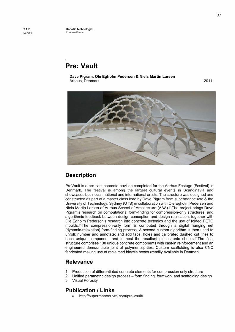
Pre: Vault
Dave Pigram, Ole Egholm Pedersen & Niels Martin Larsen Arhaus, Denmark 2011
Description
PreVault is a pre-cast concrete pavilion completed for the Aarhus Festuge (Festival) in Denmark. The festival is among the largest cultural events in Scandinavia and showcases both local, national and international artists. The structure was designed and constructed as part of a master class lead by Dave Pigram from supermanoeuvre & the University of Technology, Sydney (UTS) in collaboration with Ole Egholm Pedersen and Niels Martin Larsen of Aarhus School of Architecture (AAA).�The project brings Dave Pigram's research on computational form-finding for compression-only structures; and algorithmic feedback between design conception and design realisation; together with Ole Egholm Pederson's research into concrete tectonics and the use of folded PETG moulds.�The compression-only form is computed through a digital hanging net (dynamic-relaxation) form-finding process. A second custom algorithm is then used to unroll; number and annotate; and add tabs, holes and calibrated dashed cut lines to each unique component; and to nest the resultant pieces onto sheets.�The final structure comprises 130 unique concrete components with cast-in reinforcement and an engineered demountable joint of polymer zip-ties. Custom scaffolding is also CNC fabricated making use of reclaimed bicycle boxes (readily available in Denmark Relevance 1. Production of differentiated concrete elements for compression only structure 2. Unified parametric design process – form finding, formwork and scaffolding design 3. Visual Porosity Publication / Links
http://supermanoeuvre.com/pre-vault/
T.1.2 Survey
Robotic Technologies Concrete
1
Concrete
Pre: Vault
Dave Pigram, Ole Egholm Pedersen & Niels Martin Larsen Arhaus, Denmark 2011
Description
PreVault is a pre-cast concrete pavilion completed for the Aarhus Festuge (Festival) in Denmark. The festival is among the largest cultural events in Scandinavia and showcases both local, national and international artists. The structure was designed and constructed as part of a master class lead by Dave Pigram from supermanoeuvre & the University of Technology, Sydney (UTS) in collaboration with Ole Egholm Pedersen and Niels Martin Larsen of Aarhus School of Architecture (AAA).�The project brings Dave Pigram's research on computational form-finding for compression-only structures; and algorithmic feedback between design conception and design realisation; together with Ole Egholm Pederson's research into concrete tectonics and the use of folded PETG moulds.�The compression-only form is computed through a digital hanging net (dynamic-relaxation) form-finding process. A second custom algorithm is then used to unroll; number and annotate; and add tabs, holes and calibrated dashed cut lines to each unique component; and to nest the resultant pieces onto sheets.�The final structure comprises 130 unique concrete components with cast-in reinforcement and an engineered demountable joint of polymer zip-ties. Custom scaffolding is also CNC fabricated making use of reclaimed bicycle boxes (readily available in Denmark Relevance 1. Production of differentiated concrete elements for compression only structure 2. Unified parametric design process – form finding, formwork and scaffolding design 3. Visual Porosity Publication / Links
http://supermanoeuvre.com/pre-vault/
Concrete/Plaster
37

T.1.2 Survey
Robotic Technologies Concrete
2
Additional Images
1. Plan 2. Different structural elements
3. Assembly 4. Scaffolding detail
5. Structure detail 6. Formwork detail
T.1.2 Survey
Robotic Technologies Concrete
2
Additional Images
1. Plan 2. Different structural elements
3. Assembly 4. Scaffolding detail
5. Structure detail 6. Formwork detail
Concrete/Plaster
38

T.1.2 Survey
Robotic Technologies Plaster
1
Plaster
Robotic CastingMartin Bechthold, Nathan King & Stefano Andreani Harvard DRG / Robarch, 2012 2012
DescriptionRobotic casting workshop held at the Robarch 2012 conferences which focused on the design and production of customized bricks from a single mold. The variation of the cast elements was achieved by rotating the mold in 3D space with a robotic arm and through calculating the necessary amount of plaster to be poured in a grasshopper simulation.
RelevanceThe production strategy can be explored in other materials like concrete and proposes interesting, specific design constraints that can be explored. Also, the variation of form is achieved without the need for multiple molds, which can be a relevant strategy for construction economy.
Publication / Links http://research.gsd.harvard.edu/drg/uncategorized/robotic-casting-robarch-
2012/
Concrete/Plaster
39

T.1.2 Survey
Robotic Technologies Plaster
2
Additional Images
Robotic arm with mold Test element
Mold with negative inset element Molds and cast elements
Cast elements before assembly Assembled structure
T.1.2 Survey
Robotic Technologies Plaster
2
Additional Images
Robotic arm with mold Test element
Mold with negative inset element Molds and cast elements
Cast elements before assembly Assembled structure
Concrete/Plaster
40
T.1.2 Survey
Robotic Technologies Concrete
1
Concrete
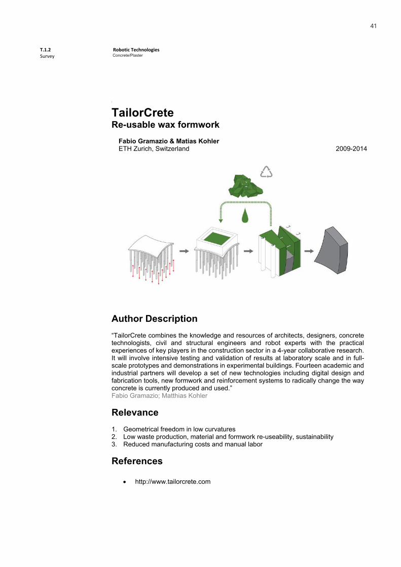
TailorCrete Re-usable wax formwork
Fabio Gramazio & Matias Kohler ETH Zurich, Switzerland 2009-2014
Author Description“TailorCrete combines the knowledge and resources of architects, designers, concrete technologists, civil and structural engineers and robot experts with the practical experiences of key players in the construction sector in a 4-year collaborative research. It will involve intensive testing and validation of results at laboratory scale and in full-scale prototypes and demonstrations in experimental buildings. Fourteen academic and industrial partners will develop a set of new technologies including digital design and fabrication tools, new formwork and reinforcement systems to radically change the way concrete is currently produced and used.” Fabio Gramazio; Matthias Kohler
Relevance1. Geometrical freedom in low curvatures 2. Low waste production, material and formwork re-useability, sustainability 3. Reduced manufacturing costs and manual labor
References
http://www.tailorcrete.com
T.1.2 Survey
Robotic Technologies Concrete
1
Concrete
TailorCrete Re-usable wax formwork
Fabio Gramazio & Matias Kohler ETH Zurich, Switzerland 2009-2014
Author Description“TailorCrete combines the knowledge and resources of architects, designers, concrete technologists, civil and structural engineers and robot experts with the practical experiences of key players in the construction sector in a 4-year collaborative research. It will involve intensive testing and validation of results at laboratory scale and in full-scale prototypes and demonstrations in experimental buildings. Fourteen academic and industrial partners will develop a set of new technologies including digital design and fabrication tools, new formwork and reinforcement systems to radically change the way concrete is currently produced and used.” Fabio Gramazio; Matthias Kohler
Relevance1. Geometrical freedom in low curvatures 2. Low waste production, material and formwork re-useability, sustainability 3. Reduced manufacturing costs and manual labor
References
http://www.tailorcrete.com
Concrete/Plaster
41
T.1.2 Survey
Robotic Technologies Concrete
2
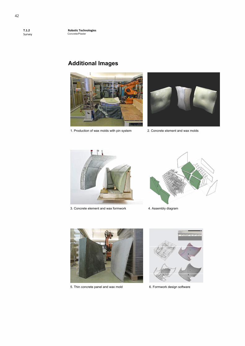
Additional Images
1. Production of wax molds with pin system 2. Concrete element and wax molds
3. Concrete element and wax formwork 4. Assembly diagram
5. Thin concrete panel and wax mold 6. Formwork design software
T.1.2 Survey
Robotic Technologies Concrete
2
Additional Images
1. Production of wax molds with pin system 2. Concrete element and wax molds
3. Concrete element and wax formwork 4. Assembly diagram
5. Thin concrete panel and wax mold 6. Formwork design software
Concrete/Plaster
42
T.1.2 Survey
Robotic Technologies Concrete
1
Concrete
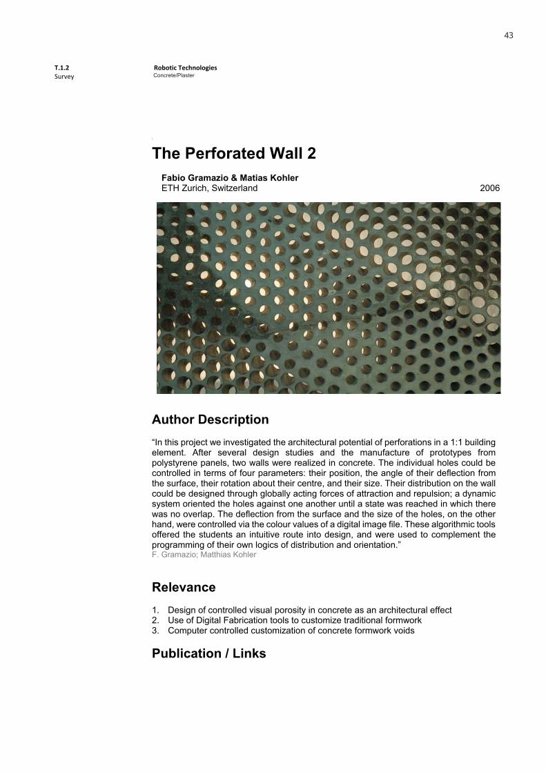
The Perforated Wall 2Fabio Gramazio & Matias Kohler ETH Zurich, Switzerland 2006
Author Description“In this project we investigated the architectural potential of perforations in a 1:1 building element. After several design studies and the manufacture of prototypes from polystyrene panels, two walls were realized in concrete. The individual holes could be controlled in terms of four parameters: their position, the angle of their deflection from the surface, their rotation about their centre, and their size. Their distribution on the wall could be designed through globally acting forces of attraction and repulsion; a dynamic system oriented the holes against one another until a state was reached in which there was no overlap. The deflection from the surface and the size of the holes, on the other hand, were controlled via the colour values of a digital image file. These algorithmic tools offered the students an intuitive route into design, and were used to complement the programming of their own logics of distribution and orientation.” F. Gramazio; Matthias Kohler
Relevance1. Design of controlled visual porosity in concrete as an architectural effect 2. Use of Digital Fabrication tools to customize traditional formwork 3. Computer controlled customization of concrete formwork voids
Publication / Links
T.1.2 Survey
Robotic Technologies Concrete
1
Concrete
The Perforated Wall 2Fabio Gramazio & Matias Kohler ETH Zurich, Switzerland 2006
Author Description“In this project we investigated the architectural potential of perforations in a 1:1 building element. After several design studies and the manufacture of prototypes from polystyrene panels, two walls were realized in concrete. The individual holes could be controlled in terms of four parameters: their position, the angle of their deflection from the surface, their rotation about their centre, and their size. Their distribution on the wall could be designed through globally acting forces of attraction and repulsion; a dynamic system oriented the holes against one another until a state was reached in which there was no overlap. The deflection from the surface and the size of the holes, on the other hand, were controlled via the colour values of a digital image file. These algorithmic tools offered the students an intuitive route into design, and were used to complement the programming of their own logics of distribution and orientation.” F. Gramazio; Matthias Kohler
Relevance1. Design of controlled visual porosity in concrete as an architectural effect 2. Use of Digital Fabrication tools to customize traditional formwork 3. Computer controlled customization of concrete formwork voids
Publication / Links
Concrete/Plaster
43

T.1.2 Survey
Robotic Technologies Concrete
2
Additional Images
1. CNC milling of plywood formwork 2. Formwork assembly
3. Formwork close-up 4. Finished surface
5. Finished panel 6. Finished panels
T.1.2 Survey
Robotic Technologies Ceramic/Brick
1
Ceramic/Brick Brick Facade of Keller AG Headquarter Gramazio & Kohler Pfungen, Swizerland 2012
Description The new front facade for the modification of a former production hall into the new headquarter of the brick manufacturer Keller in Pfungen is a freestanding, sefsupporting construction of bricks in front of a steel-glass facade Relevance The bricks are positioned and glued together by a robot. This new manufacturing process is called ROBmade The slight rotation of the bricks generates a vivid image of light and shadow and enhances the volumetric reading of the diagrid. References
http://www.gramaziokohler.com/web/e/projekte/195.html http://vimeo.com/53318164 http://vimeo.com/72354624 http://robotmetselwerk.nl/en/home-2/about-us/
Concrete/Plaster
44

T.1.2 Survey
Robotic Technologies Ceramic/Brick
1
Ceramic/Brick Brick Facade of Keller AG Headquarter Gramazio & Kohler Pfungen, Swizerland 2012
Description The new front facade for the modification of a former production hall into the new headquarter of the brick manufacturer Keller in Pfungen is a freestanding, sefsupporting construction of bricks in front of a steel-glass facade Relevance The bricks are positioned and glued together by a robot. This new manufacturing process is called ROBmade The slight rotation of the bricks generates a vivid image of light and shadow and enhances the volumetric reading of the diagrid. References
http://www.gramaziokohler.com/web/e/projekte/195.html http://vimeo.com/53318164 http://vimeo.com/72354624 http://robotmetselwerk.nl/en/home-2/about-us/
45

T.1.2 Survey
Robotic Technologies Ceramic/Brick
2
Images
Fabrication Plans
Exterior View 3 Exterior View 4
Interior View
46

T.1.2 Survey
Robotic Technologies Ceramic/Brick
2
Images
Fabrication Plans
Exterior View 3 Exterior View 4
Interior View
T.1.2 Survey
Robotic Technologies Ceramic/Brick
1
Ceramic/Brick
Flight Assembled Architecture
Gramazio & Kohler and Raffaello D`AndreaFRAC Centre Orléans, France 2011-2012
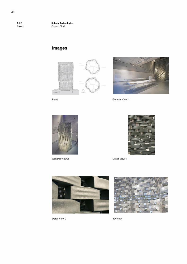
DescriptionFlight Assembled Architecture consists of over 1.500 modules which are placed by a multitude of quadrotor helicopters, collaborating according to mathematical algorithms that translate digital design data to the behavior of the flying machines. In this way, the flying vehicles, together, extend themselves as “living” architectural machines and complete the composition from their dynamic formation of movement and building performance.
RelevanceFlight Assembled Architecture is the first architectural installation assembled by flying robots, free from the touch of human hands. The installation is an expression of a rigorous architectural design by Gramazio & Kohler and a visionary robotic system by Raffaello D’Andrea.
References
http://www.gramaziokohler.com/web/e/projekte/209.html http://vimeo.com/33713231
Gramazio & Kohler and Raffaelo D’Andrea
47
T.1.2 Survey
Robotic Technologies Ceramic/Brick
2
Images
Plans General View 1
General View 2 Detail View 1
Detail View 2 3D View
48

T.1.2 Survey
Robotic Technologies Ceramic/Brick
1
Ceramic/Brick
Gantenbein Vineyard Facade
Gramazio & Kohler Fläsch, Switzerland 2006
DescriptionThe masonry of the vineyard’s façade is a non-standardised brick façade that looks like an enormous basket filled with grapes. According to the angle at which they are set, the individual bricks each reflect light differently and thus take on different degrees of lightness. Similarly to pixels on a computer screen they add up to a distinctive image and thus communicate the identity of the vineyard. The wall elements were manufactured as a pilot project in research facilities at the ETH Zurich, transported by lorry to the construction site, and installed using a crane.
RelevanceThe robotic production method that Gramazio & Kohler developed at the ETH enabled them to lay each one of the 20,000 bricks precisely according to programmed parameters—at the desired angle and at the exact prescribed intervals. The bricklaying aswell as the design process were pioneering works.
References http://dfab.arch.ethz.ch/web/e/forschung/52.html http://www.robmade.ch/en/projects/winery_gantenbein/ http://www.gramaziokohler.com/web/e/bauten/52.html The Robotic Touch - How Robots Change Architecture
49

T.1.2 Survey
Robotic Technologies Ceramic/Brick
2
Images
Concept 3D Model 1 Concept 3D Model 2
Wall Module Exterior View 1
Exterior View 2 Interior View
50
T.1.2 Survey
Robotic Technologies Ceramic/Brick
1
Ceramic/Brick
Pike Loop
Gramazio & Kohler New York, USA 2009
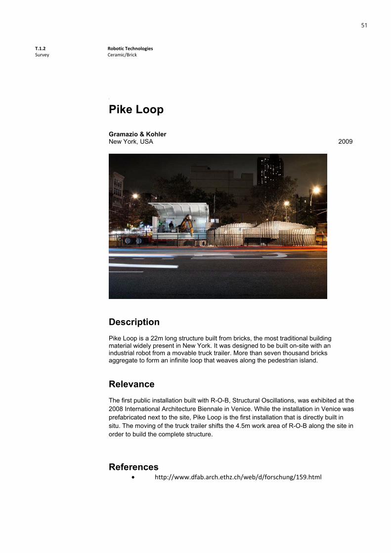
DescriptionPike Loop is a 22m long structure built from bricks, the most traditional building material widely present in New York. It was designed to be built on-site with an industrial robot from a movable truck trailer. More than seven thousand bricks aggregate to form an infinite loop that weaves along the pedestrian island.
RelevanceThe first public installation built with R-O-B, Structural Oscillations, was exhibited at the 2008 International Architecture Biennale in Venice. While the installation in Venice was prefabricated next to the site, Pike Loop is the first installation that is directly built in situ. The moving of the truck trailer shifts the 4.5m work area of R-O-B along the site in order to build the complete structure.
References http://www.dfab.arch.ethz.ch/web/d/forschung/159.html
51
T.1.2 Survey
Robotic Technologies Ceramic/Brick
2
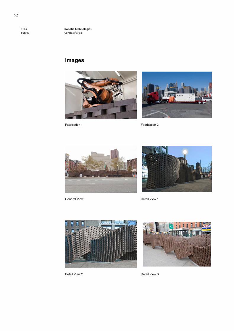
Images
Fabrication 1 Fabrication 2
General View Detail View 1
Detail View 2 Detail View 3
52

T.1.2 Survey
Robotic Technologies Ceramic/Brick
1
Ceramic/Brick
Structural Oscilations
Gramazio&Kohler Venice, Italy 2007-2008
DescriptionFor the exhibition “Explorations” -the Swiss contribution to the 11th Venice Architectural Biennale- Gramazio & Kohler conceived a 100 meter long brick wall to run as a continuous ribbon through the Swiss pavilion. The design of the wall followed algorithmic rules and was built on site at the Giardini, the grounds of the Biennale, by the R-O-B mobile robotic fabrication unit.
RelevanceThe wall’s design was conceived as a system with open parameters. The course of a single, continuous curve carried all the generative information necessary to determine the design. This curve functioned as a conceptual interface, which enabled the needs of the individual exhibited groups to be negotiated.
References http://dfab.arch.ethz.ch/web/e/forschung/142.html
53

T.1.2 Survey
Robotic Technologies Ceramic/Brick
2
Images
Plan Modules
Fabrication General View 1
General View 2 Detail View
54
T.1.2 Survey
Robotic Technologies Ceramic/Brick
1
Ceramic/Brick
The Programmed Column 2 Gramazio & Kohler ETH Zurich, Switzerland 2010
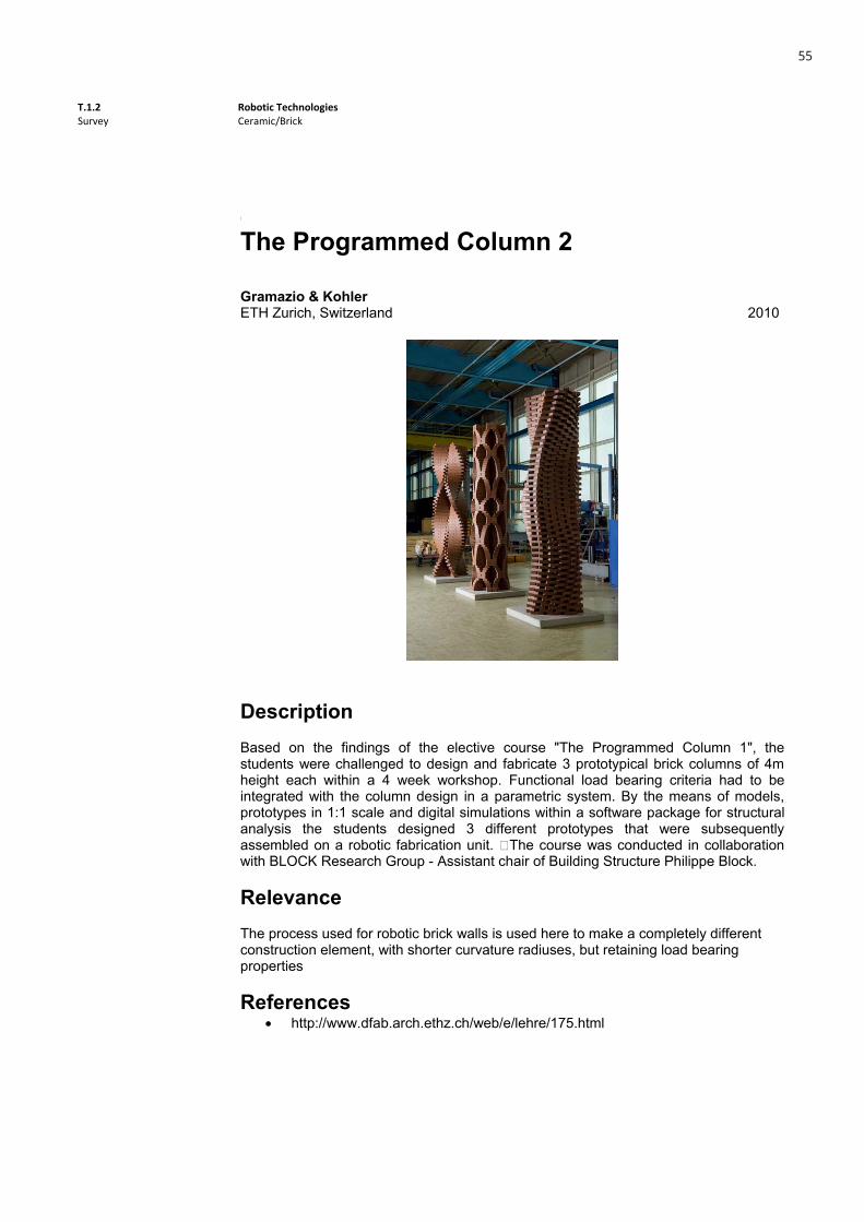
Description Based on the findings of the elective course "The Programmed Column 1", the students were challenged to design and fabricate 3 prototypical brick columns of 4m height each within a 4 week workshop. Functional load bearing criteria had to be integrated with the column design in a parametric system. By the means of models, prototypes in 1:1 scale and digital simulations within a software package for structural analysis the students designed 3 different prototypes that were subsequently assembled on a robotic fabrication unit. �The course was conducted in collaboration with BLOCK Research Group - Assistant chair of Building Structure Philippe Block. Relevance The process used for robotic brick walls is used here to make a completely different construction element, with shorter curvature radiuses, but retaining load bearing properties References
http://www.dfab.arch.ethz.ch/web/e/lehre/175.html
55
T.1.2 Survey
Robotic Technologies Ceramic/Brick
2
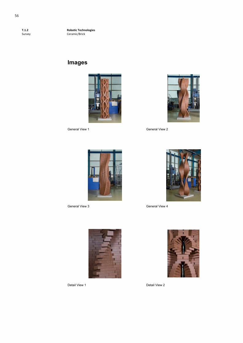
Images
General View 1 General View 2
General View 3 General View 4
Detail View 1 Detail View 2
56

T.1.2 Survey
Robotic Technologies Wood
1
Wood
ICD/ITKE Reaseach Pavillion 2010Achim Menges Stuggart, Germany 2010
DescriptionThe challenge was to build a temporary wooden research pavilion that pretended to demonstrate the latest computational design developments. The building was a research project realized by a partnership between Achim Menges and University of Stuttgart.
Relevance
This research pavilion and its computational form design process, results directly of the physics and mechanics behavior of the material used to its construction. The parametric design and the structure needs were defined through physical experiments. The structure is completely based on the elastic bending behavior of birch plywood strips, which were completely robotically manufactured as planar elements.
References
http://www.achimmenges.net/?p=4443 http://icd.uni-stuttgart.de/?p=4458
57
T.1.2 Survey
Robotic Technologies Wood
2
Images
Caption 1 Caption 2
Caption 3 Caption 4
Caption 5 Caption 6
58
T.1.2 Survey
Robotic Technologies Wood
1
Wood
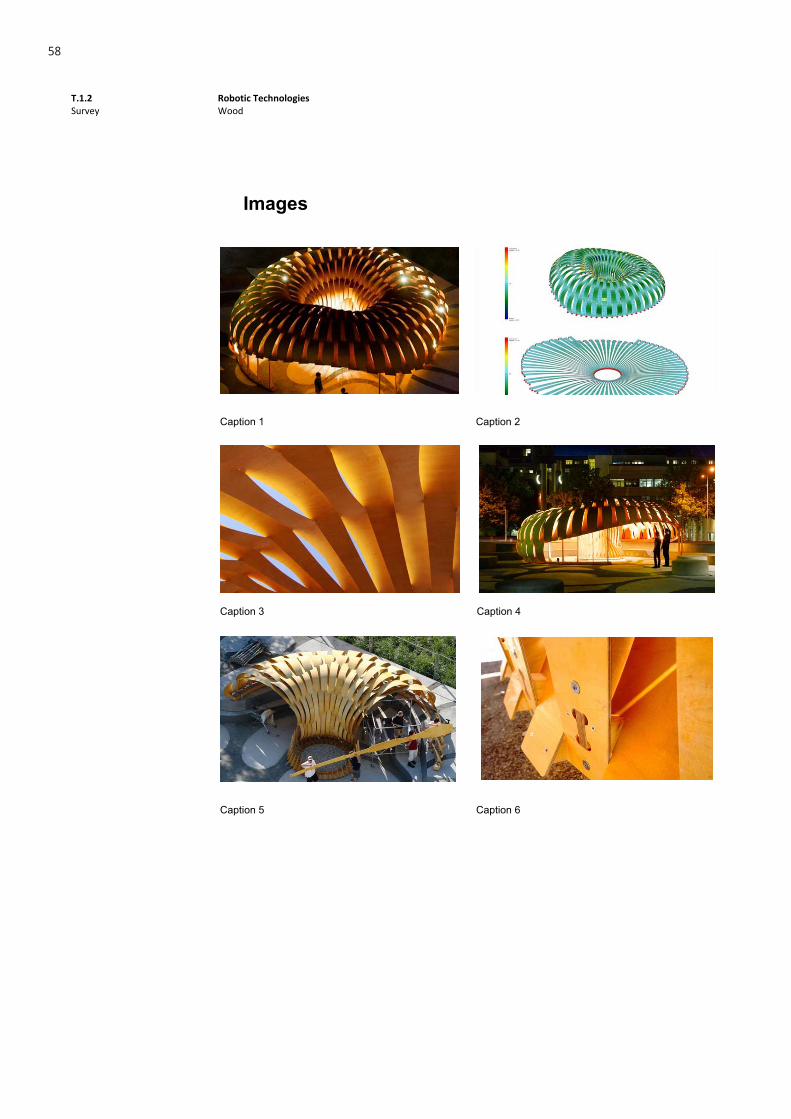
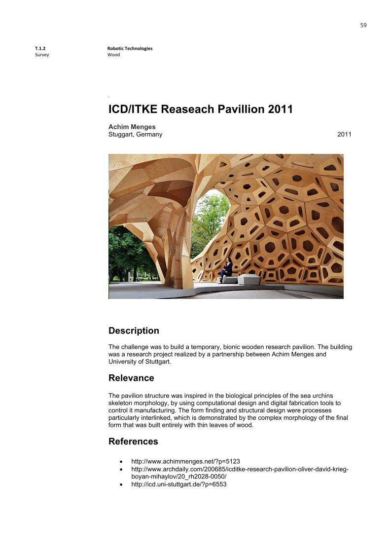
ICD/ITKE Reaseach Pavillion 2011Achim Menges Stuggart, Germany 2011
DescriptionThe challenge was to build a temporary, bionic wooden research pavilion. The building was a research project realized by a partnership between Achim Menges and University of Stuttgart.
Relevance
The pavilion structure was inspired in the biological principles of the sea urchins skeleton morphology, by using computational design and digital fabrication tools to control it manufacturing. The form finding and structural design were processes particularly interlinked, which is demonstrated by the complex morphology of the final form that was built entirely with thin leaves of wood.
References
http://www.achimmenges.net/?p=5123 http://www.archdaily.com/200685/icditke-research-pavilion-oliver-david-krieg-
boyan-mihaylov/20_rh2028-0050/ http://icd.uni-stuttgart.de/?p=6553
59

T.1.2 Survey
Robotic Technologies Wood
2
Images
Caption 1 Caption 2
Caption 3 Caption 4
Caption 5 Caption 6
60

T.1.2 Survey
Robotic Technologies Material
1
Wood
Robot Chainsaw StoolTibor Weissmahr &Tom PawlofskyKarlsruhe, Germany 2013
DescriptionThe Robot Chainsaw Stools has one main purpose: to carve stools from a wooden trunk.
Relevance
The main purpose of this project is to carve furniture from a wooden trunk by using a Robotic Arm with a Chainsaw. The sculpting process is defined by computational means.
References
https://www.youtube.com/watch?v=vgvlP87Ju5Y http://www.theverge.com/2013/1/23/3907726/chainsaw-robot-programmed-to-
carve-two-stools-from-a-single-log
Wood
61

T.1.2 Survey
Robotic Technologies Material
2
Images
Caption 1 Caption 2
Caption 3
Wood
62
T.1.2 Survey
Robotic Technologies Material
1
Wood
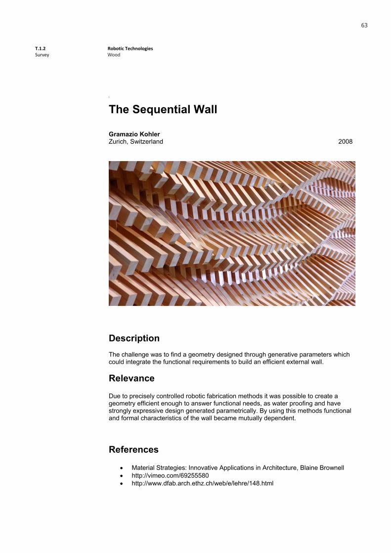
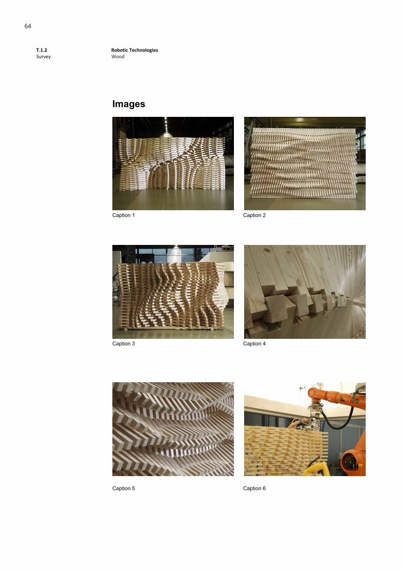
The Sequential Wall
Gramazio Kohler Zurich, Switzerland 2008
DescriptionThe challenge was to find a geometry designed through generative parameters which could integrate the functional requirements to build an efficient external wall.
Relevance
Due to precisely controlled robotic fabrication methods it was possible to create a geometry efficient enough to answer functional needs, as water proofing and have strongly expressive design generated parametrically. By using this methods functional and formal characteristics of the wall became mutually dependent.
References
Material Strategies: Innovative Applications in Architecture, Blaine Brownell http://vimeo.com/69255580 http://www.dfab.arch.ethz.ch/web/e/lehre/148.html
Wood
63
T.1.2 Survey
Robotic Technologies Material
2
Images
Caption 1 Caption 2
Caption 3 Caption 4
Caption 5 Caption 6
Wood
64
T.1.2 Survey
Robotic Technologies Material
1
Wood
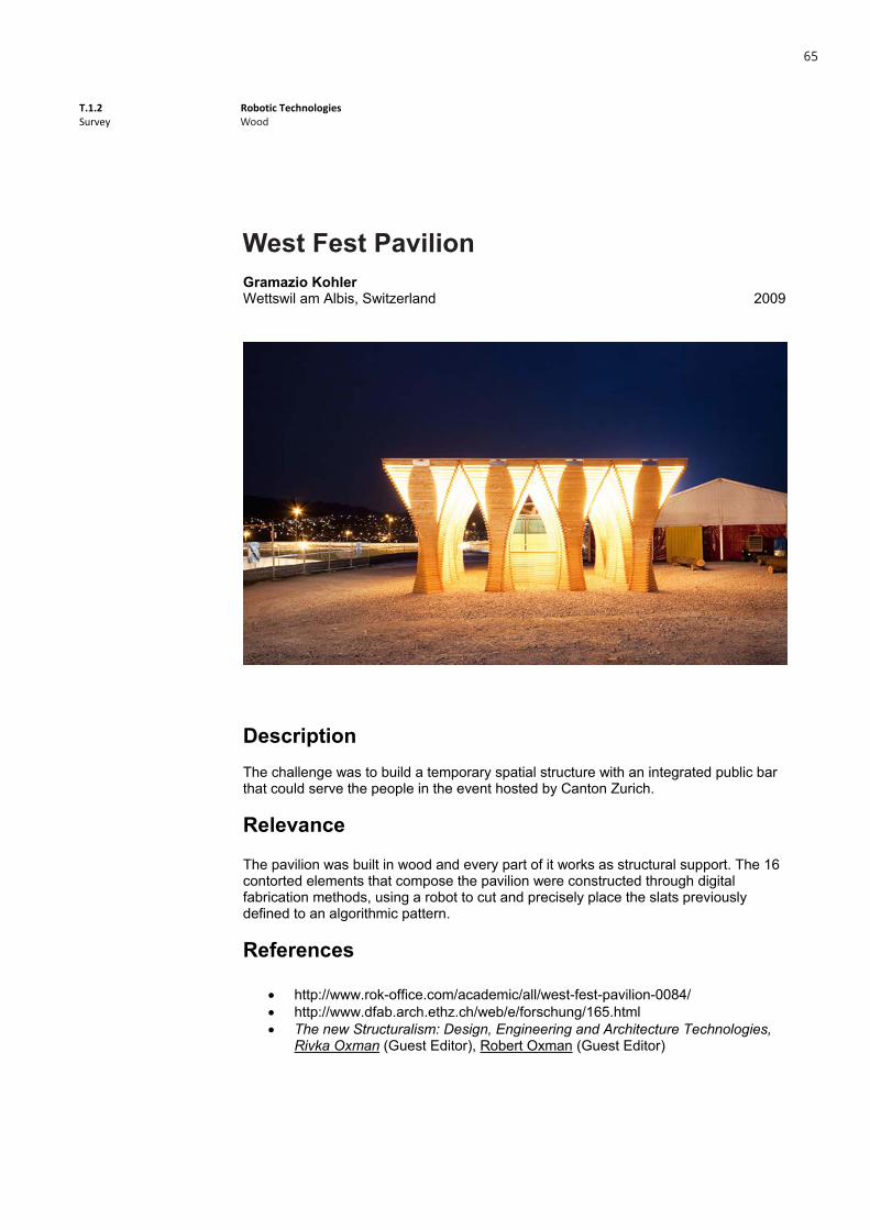
West fest pavilionGramazio Kohler Wettswil am Albis, Switzerland 2009
DescriptionThe challenge was to build a temporary spatial structure with an integrated public bar that could serve the people in the event hosted by Canton Zurich.
Relevance
The pavilion was built in wood and every part of it works as structural support. The 16 contorted elements that compose the pavilion were constructed through digital fabrication methods, using a robot to cut and precisely place the slats previously defined to an algorithmic pattern.
References
http://www.rok-office.com/academic/all/west-fest-pavilion-0084/ http://www.dfab.arch.ethz.ch/web/e/forschung/165.html The new Structuralism: Design, Engineering and Architecture Technologies,
Rivka Oxman (Guest Editor), Robert Oxman (Guest Editor)
Wood
West Fest Pavilion
65

T.1.2 Survey
Robotic Technologies Material
2
Images
Caption 1 Caption 2
Caption 3 Caption 4
Caption 5 Caption 6
Wood
66

T.1.2 Survey
Robotic Technologies Metal
1
Metal
Auto-Eclipsis
Nathan King, Jonathan Grinham, Design Robotics Group_Harvard GSD & SOAS Harvard, USA 2012
DescriptionThis research explores the potential for the robotic fabrication of novel, complex, high performance metal shading systems. The Eclipsis facade system utilizes innovative circular geometry in the form of laser-cut holes to produce a series of folded tabs at calculated degrees to create a specialized yet customizable high-performance facade system. The system's algorithmic logic is designed for customization taking into account varying degrees of privacy, spatial condition and local environmental performance criteria including daylighting and ventilation. The logic of each semi-perforation is simple and controlled by parameters defined only by dimension, location, rotation, and the angle of the folded tab. Complexity emerges in the part-to-whole relationship where the aggregation of instantiated parametric geometry provides regulated infinite-variation of tab size and rotation.
Relevance1. Infinite-variation of tab size and rotation 2. Architectural customization through computational means 3. Low dependency on man-power and manual labor
References http://www.spaghettionastick.com/AUTO-ECLIPSIS
67

T.1.2 Survey
Robotic Technologies Metal
2
Images
Parametric Definition 1 Parametric Definition 2
Fabrication 1 Fabrication 2
Fabrication 3 Fabrication 4
68
T.1.2 Survey
Robotic Technologies Metal
1
Metal
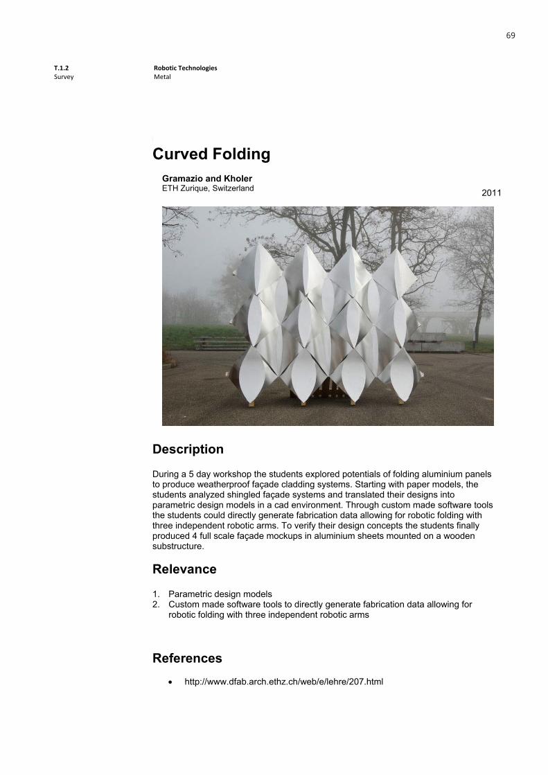
Curved FoldingGramazio and Kholer ETH Zurique, Switzerland 2011
Description
During a 5 day workshop the students explored potentials of folding aluminium panels to produce weatherproof façade cladding systems. Starting with paper models, the students analyzed shingled façade systems and translated their designs into parametric design models in a cad environment. Through custom made software tools the students could directly generate fabrication data allowing for robotic folding with three independent robotic arms. To verify their design concepts the students finally produced 4 full scale façade mockups in aluminium sheets mounted on a wooden substructure.
Relevance
1. Parametric design models 2. Custom made software tools to directly generate fabrication data allowing for
robotic folding with three independent robotic arms
References http://www.dfab.arch.ethz.ch/web/e/lehre/207.html
T.1.2 Survey
Robotic Technologies Metal
1
Metal
Curved FoldingGramazio and Kholer ETH Zurique, Switzerland 2011
Description
During a 5 day workshop the students explored potentials of folding aluminium panels to produce weatherproof façade cladding systems. Starting with paper models, the students analyzed shingled façade systems and translated their designs into parametric design models in a cad environment. Through custom made software tools the students could directly generate fabrication data allowing for robotic folding with three independent robotic arms. To verify their design concepts the students finally produced 4 full scale façade mockups in aluminium sheets mounted on a wooden substructure.
Relevance
1. Parametric design models 2. Custom made software tools to directly generate fabrication data allowing for
robotic folding with three independent robotic arms
References http://www.dfab.arch.ethz.ch/web/e/lehre/207.html
69

T.1.2 Survey
Robotic Technologies Metal
2
Images
General View 1 General View 2
Detail View 1 Detail View 2
Detail View 3 Fabrication
T.1.2 Survey
Robotic Technologies Metal
2
Images
General View 1 General View 2
Detail View 1 Detail View 2
Detail View 3 Fabrication
70

T.1.2 Survey
Robotic Technologies Metal
1
Metal
Metal Sky
GSD Justin Lavallee, Rachel Vroman, Yair Keshet, Sola Grantham Harvard, USA 2011
DescriptionThe project investigates the role of design automation in the context of a parametrically variable design through the design and production of a highly customized, parametrically varied sheet metal ceiling. The integrated design to robotic fabrication process involves the development of a custom automation tool developed for a parametric computational design environment. Design variations allow for individualized sheet metal elements that can be customized without impacting the time and cost of fabrication.
Relevance1. Design automation in the context of a parametrically variable design 2. Elements customized without impact on time and cost of fabrication
References
http://research.gsd.harvard.edu/drg/robotic-systems/metal-sky-2/
71
T.1.2 Survey
Robotic Technologies Metal
2
Images
Detail View 1
72

T.1.2 Survey
Robotic Technologies Metal
1
Metal
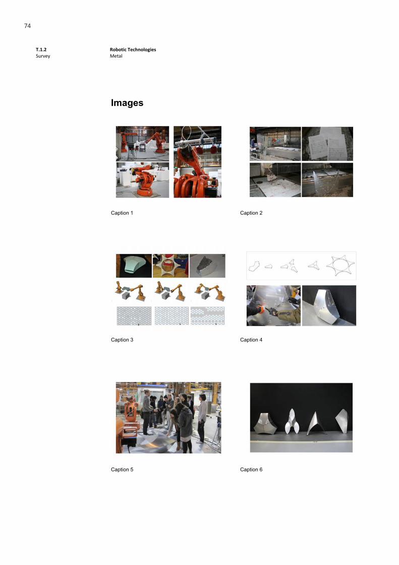
Workshop Robotic Facade Fabrication
Gregory Epps, Daniel Piker & Jelle Feringa Rotterdam, Netherlands 2011
DescriptionRoboFold is an attempt to completely re-think how metal can be formed. It is a system that works with the material and not against it. It is a system built around the gentle bends and sharp crease lines of curved folding in sheet material. It is a system that allows a product to exist at many scales through an iterative design and development process, letting hand folding of paper and other materials naturally exist alongside the robotic folding of metal.
RelevanceThe RoboFold system has the potencial to materialize new aesthetic possibilities, until now only imaginable through the use of digital design tools.
References
http://eliseelsacker.wordpress.com/2012/01/15/robotic-facade-fabrication-at-tudelft/
73
T.1.2 Survey
Robotic Technologies Metal
2
Images
Caption 1 Caption 2
Caption 3 Caption 4
Caption 5 Caption 6
74

T.1.2 Survey
Robotic Technologies Styrofoam
1
Styrofoam
Automated FoamDome
Synthetic Lab & Thibault Schwartz Le Mans - Rotterdam 2012
DescriptionBeing part of the Synthetic 2012 workshop, this project uses a robotic arm driven hot wire to cut the foam into the designed form in order to make the customized components necessary to assemble into the final form.
RelevanceDespite the lack of structural resistance, the usage of the heat sensivity and lightweight properties of the material with the appliance of the robotic arm driven hot wire resulted in a clean, quick and inexpensive way of producing free forms at diverse scales, making this approach adequated for real size models
References http://thibaultschwartz.com/?g1_work=automated‐foamdome‐2synthetic‐
2012
75
T.1.2 Survey
Robotic Technologies Styrofoam
2
Images
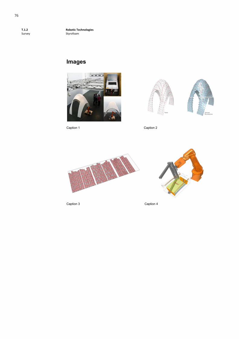
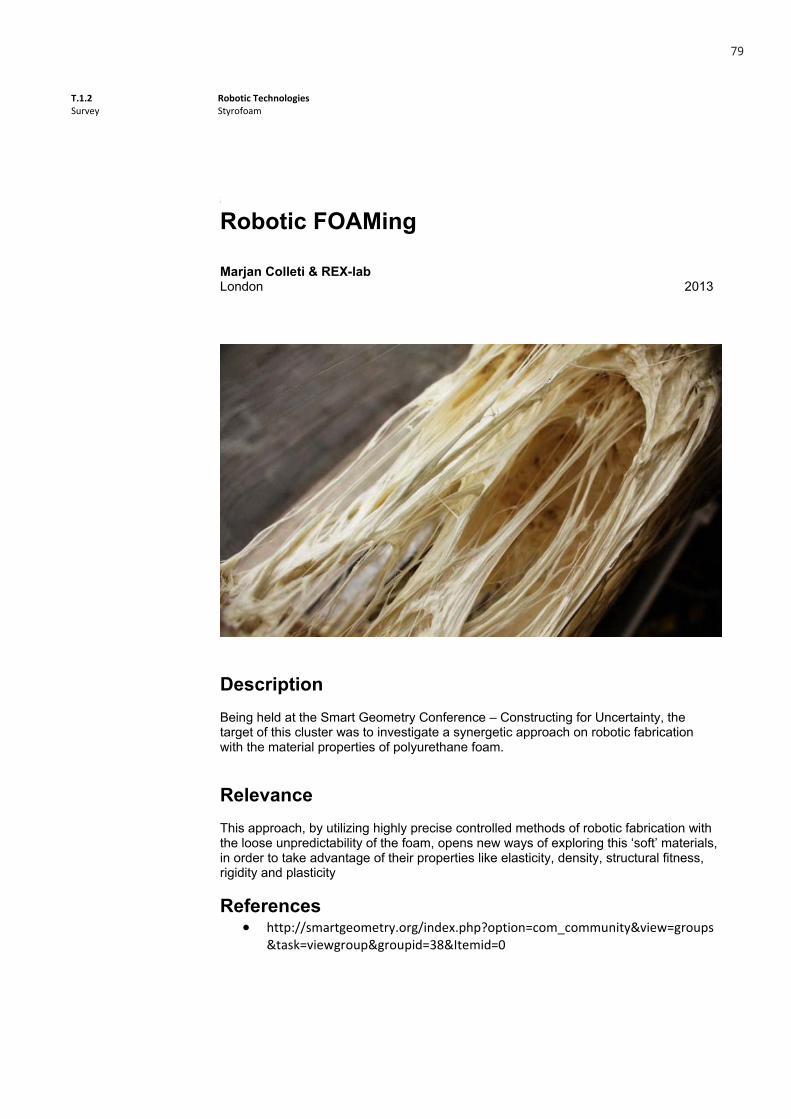
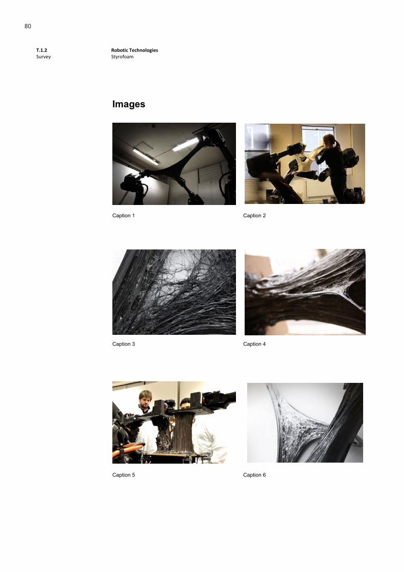
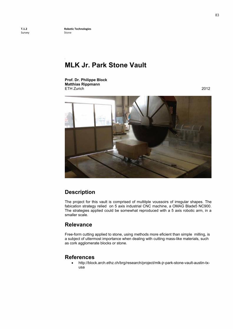
Caption 1 Caption 2
Caption 3 Caption 4
76

T.1.2 Survey
Robotic Technologies Styrofoam
1
Styrofoam
Hyperbody
ROKDelft 2012
DescriptionWith the aim of analyzing and rethinking complex free form geometries in terms of manufacturing constraints, this 2 week digital fabrication workshop used the RhinoVAULT.rv to design a cut-foam pavillion
RelevanceAlthough the individual components must be ruled surfaces, considering the hot-wiring limitations, the overall shape can still be free. Also, in qualitative terms, this approach could be also applied to other materials, like stone or concrete.
References http://designplaygrounds.com/deviants/msc2-studio-at-hyperbody-at-tu-delft/
77

T.1.2 Survey
Robotic Technologies Styrofoam
2
Images
Caption 1 Caption 2
Caption 3 Caption 4
78
T.1.2 Survey
Robotic Technologies Styrofoam
1
Styrofoam
Robotic FOAMing
Marjan Colleti & REX-lab London 2013
DescriptionBeing held at the Smart Geometry Conference – Constructing for Uncertainty, the target of this cluster was to investigate a synergetic approach on robotic fabrication with the material properties of polyurethane foam.
RelevanceThis approach, by utilizing highly precise controlled methods of robotic fabrication with the loose unpredictability of the foam, opens new ways of exploring this ‘soft’ materials, in order to take advantage of their properties like elasticity, density, structural fitness, rigidity and plasticity
References http://smartgeometry.org/index.php?option=com_community&view=groups
&task=viewgroup&groupid=38&Itemid=0
79
T.1.2 Survey
Robotic Technologies Styrofoam
2
Images
Caption 1 Caption 2
Caption 3 Caption 4
Caption 5 Caption 6
80

T.1.2 Survey
Robotic Technologies Styrofoam
1
Styrofoam
Synthetic 2012
Synthetic Lab & Jelle Feringa Le Mans - Rotterdam 2012
DescriptionMaking use of a hot wire driven by a robotic arm, this team was able to sculpt out of various blocks of foam the various components designed previously in the digital environment
RelevanceDespite the lack of structural resistance, the usage of the heat sensivity and lightweight properties of the material with the appliance of the robotic arm driven hot wire resulted in a clean, quick and inexpensive way of producing free forms at diverse scales, making this approach adequated for real size models
References http://synthetic2012.com/synthetic‐foam‐le‐mans‐rotterdam/
81

T.1.2 Survey
Robotic Technologies Styrofoam
2
Images
Caption 1 Caption 2
Caption 3
82
T.1.2 Survey
Robotic Technologies Other
1
Other
MLK Jr. Park Stone Vault
Prof. Dr. Philippe Block Matthias Rippmann ETH Zurich 2012
DescriptionThe project for this vault is comprised of multitple voussoirs of irregular shapes. The fabication strategy relied on 5 axis industrial CNC machine, a OMAG Blade5 NC900. The strategies applied could be somewhat reproduced with a 5 axis robotic arm, in a smaller scale.
RelevanceFree-form cutting applied to stone, using methods more eficient than simple milling, is a subject of uttermost importance when dealing with cutting mass-like materials, such as cork agglomerate blocks or stone.
References http://block.arch.ethz.ch/brg/research/project/mlk-jr-park-stone-vault-austin-tx-
usa
Stone
83

T.1.2 Survey
Robotic Technologies Other
2
Images
Model Model
CNC axis Production detail
Machining process Production detail
Stone
84
T.1.2 Survey
Robotic Technologies Other
1
Other
ICD/ITKE Research Pavillion 2012
Achim Menges Jan Knippers Stuttgart University 2012
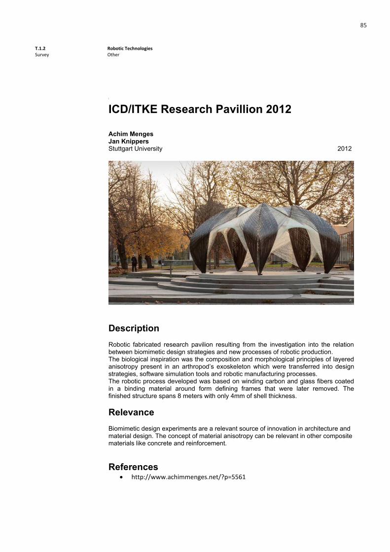
DescriptionRobotic fabricated research pavilion resulting from the investigation into the relation between biomimetic design strategies and new processes of robotic production. The biological inspiration was the composition and morphological principles of layered anisotropy present in an arthropod’s exoskeleton which were transferred into design strategies, software simulation tools and robotic manufacturing processes. The robotic process developed was based on winding carbon and glass fibers coated in a binding material around form defining frames that were later removed. The finished structure spans 8 meters with only 4mm of shell thickness.
RelevanceBiomimetic design experiments are a relevant source of innovation in architecture and material design. The concept of material anisotropy can be relevant in other composite materials like concrete and reinforcement.
References http://www.achimmenges.net/?p=5561
85
T.1.2 Survey
Robotic Technologies Other
2
Images
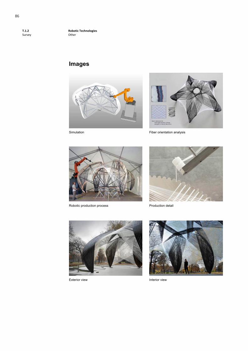
Simulation Fiber orientation analysis
Robotic production process Production detail
Exterior view Interior view
86

T.1.2 Survey
Robotic Technologies Other
1
Other
Robotic Manipulation of Carbon Fiber
Super Tex Composites Place, Country 2013
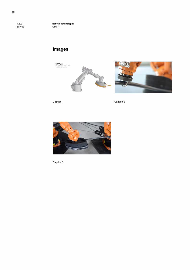
DescriptionThe robotic manipulation of carbon fibers reinforced tubes in the automotive industry allows de development of ultralight chassis performing a base shape. In order to winding for mass production, there were made 3D sketches about the fabrication concept. KUKAprc, (parametric robot control for grasshopper), a visual robot programming, enabled the robot simulation with the winding parameters as well as a dynamic programming with parametric objects. It was possible to simulate a full kinematic robot doing the winding process.
Relevance
1. Programming industrial robots directly out of the parametric modelling environment 2. Mass customization option for the automated generation of numbered robot control
files
References http://www.robotsinarchitecture.org/KUKA KR125/2 http://www.robotsinarchitecture.org/kuka-prc http://www.youtube.com/watch?v=6WrjSBS7XBE
Other
87
T.1.2 Survey
Robotic Technologies Other
2
Images
Caption 1 Caption 2
Caption 3
Other
88

T.1.2 Survey
Robotic Technologies Robots
1
Delta Robot
Description A Delta robot is a kind of parallel mechanism which consists of three arms working in a parallelogram fashion, ensuring that the tip where the end-effector is located is always parallel to the robot. The main advantage of this kind of industrial robot is its speed and precision; this is why it was invented to serve packaging assembly lines.
Applications in other fields
Delta Robot
89

90

T.1.2 Survey
Robotic Technologies Robots
1
Dual Arm Robot
Description This kind of robot is used for manipulation of objects and increased possibilities. One arm may pick an object and move it with a high degree of freedom while the other arm, with a similar high degree of freedom may operate on the objects, assembling, cutting or whichever end-effector is applied.
Applications in other fields
91

92