Robotic hand pose estimation based on stereo vision and...
17
Journal of Intelligent and Robotic Systems manuscript No. (will be inserted by the editor) Robotic hand pose estimation based on stereo vision and GPU-enabled internal graphical simulation Pedro Vicente · Lorenzo Jamone · Alexandre Bernardino Received: ... / Accepted: ... Abstract Humanoid robots have complex kinematic chains whose modeling is error prone. If the robot model is not well calibrated, its hand pose cannot be deter- mined precisely from the encoder readings, and this affects reaching and grasping accuracy. In our work, we propose a novel method to simultaneously i) estimate the pose of the robot hand, and ii) calibrate the robot kinematic model. This is achieved by combining stereo vi- sion, proprioception, and a 3D computer graphics model of the robot. Notably, the use of GPU programming allows to perform the estimation and calibration in real time during the execution of arm reaching movements. Proprioceptive information is exploited to generate hy- potheses about the visual appearance of the hand in the camera images, using the 3D computer graphics model of the robot that includes both kinematic and texture information. These hypotheses are compared with the actual visual input using particle filtering, to obtain both i) the best estimate of the hand pose and ii) a set of joint offsets to calibrate the kinematics of the robot model. We evaluate two different approaches to estimate the 6D pose of the hand from vision (silhouette segmen- tation and edges extraction) and show experimentally that the pose estimation error is considerably reduced with respect to the nominal robot model. Moreover, the GPU implementation ensures a performance about Parts of this manuscript were previously presented at the IEEE International Conference on Autonomous Robot Systems and Competitions (ICARSC 2015), Vila Real P. Vicente, L. Jamone and A. Bernardino Avenida Rovisco Pais, 1 - Torre Norte 1049-001 Lisboa, Portugal Tel.: +351218418050 E-mail: {pvicente,ljamone,alex}@isr.ist.utl.pt Fig. 1: The iCub humanoid robot imagining hypotheses of its hand pose. 3 times faster than the CPU one, allowing real-time operation. Keywords robot hand pose estimation · robot self-calibration · humanoid robots · 3D graphical simulation · GPU programming · online reaching adaptation · computer vision 1 Introduction Everyday tasks like grasping an object with precision or pushing an electrical plug into a socket are quite simple for humans, who deal with these activities on a daily ba- sis, but complex and challenging for autonomous robots. A correct kinematic model of the limbs structure is of paramount importance when performing such tasks. In particular, accurate models of the arms and hands are crucial in order to properly grasp and manipulate ob- jects. Moreover, real time reaching and grasping tasks in robots are very often performed without any visual feed- back control approach [8, 38]. In that case, if the robot
Transcript of Robotic hand pose estimation based on stereo vision and...

Journal of Intelligent and Robotic Systems manuscript No.(will be inserted by the editor)
Robotic hand pose estimation based on stereo vision andGPU-enabled internal graphical simulation
Pedro Vicente · Lorenzo Jamone · Alexandre Bernardino
Received: ... / Accepted: ...
Abstract Humanoid robots have complex kinematic
chains whose modeling is error prone. If the robot model
is not well calibrated, its hand pose cannot be deter-
mined precisely from the encoder readings, and this
affects reaching and grasping accuracy. In our work, we
propose a novel method to simultaneously i) estimate
the pose of the robot hand, and ii) calibrate the robot
kinematic model. This is achieved by combining stereo vi-
sion, proprioception, and a 3D computer graphics model
of the robot. Notably, the use of GPU programming
allows to perform the estimation and calibration in real
time during the execution of arm reaching movements.
Proprioceptive information is exploited to generate hy-
potheses about the visual appearance of the hand in the
camera images, using the 3D computer graphics model
of the robot that includes both kinematic and textureinformation. These hypotheses are compared with the
actual visual input using particle filtering, to obtain
both i) the best estimate of the hand pose and ii) a set
of joint offsets to calibrate the kinematics of the robot
model. We evaluate two different approaches to estimate
the 6D pose of the hand from vision (silhouette segmen-
tation and edges extraction) and show experimentally
that the pose estimation error is considerably reduced
with respect to the nominal robot model. Moreover,
the GPU implementation ensures a performance about
Parts of this manuscript were previously presented at the IEEEInternational Conference on Autonomous Robot Systems andCompetitions (ICARSC 2015), Vila Real
P. Vicente, L. Jamone and A. BernardinoAvenida Rovisco Pais, 1 - Torre Norte1049-001 Lisboa, PortugalTel.: +351218418050E-mail: {pvicente,ljamone,alex}@isr.ist.utl.pt
Fig. 1: The iCub humanoid robot imagining hypotheses
of its hand pose.
3 times faster than the CPU one, allowing real-time
operation.
Keywords robot hand pose estimation · robot
self-calibration · humanoid robots · 3D graphical
simulation · GPU programming · online reaching
adaptation · computer vision
1 Introduction
Everyday tasks like grasping an object with precision or
pushing an electrical plug into a socket are quite simple
for humans, who deal with these activities on a daily ba-
sis, but complex and challenging for autonomous robots.
A correct kinematic model of the limbs structure is of
paramount importance when performing such tasks. In
particular, accurate models of the arms and hands are
crucial in order to properly grasp and manipulate ob-
jects. Moreover, real time reaching and grasping tasks in
robots are very often performed without any visual feed-
back control approach [8,38]. In that case, if the robot
2 Pedro Vicente et al.
internal model is not accurate enough, the tasks will
not be successful. However, a precise analytical model
of the kinematic chain of a humanoid robot with several
degrees of freedom can be difficult to obtain due to hard-
to-model aspects (e.g. friction) and changes that might
occur over time (e.g. misalignment of a joint rotation
axis). Therefore, to correctly estimate the hand pose,
a continuous re-calibration of the model is desirable.
In general, this can be done by exploiting multisensory
information coming from the robot sensors, together
with advanced techniques for learning and estimation.Indeed, if we consider human studies, it is known that
five-months-old infants already use vision to correct the
hand position and orientation during movements [27],
with performance that improves during development [1].
However, after nine months this visual guidance almost
disappears, and children become able to plan a proper
hand trajectory at the movement onset [26]. This might
suggest that an internal model has been learned by com-
bining visual and proprioceptive information during the
first months, and later exploited to improve the control.
Moreover, motor learning theories postulate that learned
internal models might be used to make predictions, that
are combined with the actual sensory feedback through
Bayesian integration to improve the estimation of the
current state of the system [23]. Overall, these studies
put forward the idea that the processes of model cali-
bration and state estimation might support each other
in natural systems, and therefore provide us with fur-
ther motivation to explore similar strategies in artificial
systems.
In our work we propose a novel computational frame-
work to simultaneously i) estimate the 6D pose of therobot hand and ii) calibrate the kinematic model of the
robot arm. While the robot model is exploited to facili-
tate the hand pose estimation, the estimates are used
to calibrate the model itself. These two processes are
realized online in real time during reaching movements.We apply our framework to the iCub humanoid robot
[29].
In this paper we implement the internal model of the
robot in a 3D graphical simulation environment using
the game engine Unityr, modeling both the kinemat-
ics and appearance (texture) of the robot. The nom-
inal kinematics is provided by the iKin library [36],
part of the YARP/iCub software repository (https:
//github.com/robotology). The robot texture is mod-
eled based on the open-source CAD documentation of
the robot, that can be found online at http://wiki.
icub.org/wiki/RobotCub. The internal model is used
to generate hypotheses about the hand appearance in
the eye cameras, based on the arm and head joint angles
(i.e. proprioception). These hypotheses are compared
to the actual hand appearance in the images coming
from the cameras (i.e. stereo vision). Using kernel den-
sity estimation and a maximum likelihood approach, we
compute the estimate of the current hand pose as well
as a set of joint angles corrections to calibrate the model
kinematics.
A preliminary version of the proposed framework has
been presented in a previous work [44], in which we
developed a CPU implementation of the method. We
realized that there was a computational bottleneck in
the hypotheses generation step and in the comparisonto the visual input, which are operations that can be
easily parallelized. To tackle this problem, in this paper,
we present an efficient GPU implementation of our com-
putational framework that makes it possible to use the
system in real time. Moreover, we evaluate two different
approaches for the visual estimation. The first approach
is simpler, and it consists of comparing only the silhou-
ettes of the real and simulated hand, that are obtained
by color-based segmentation. In the second approach,
instead, the edges extracted from the real and simulated
hand are compared. The use of edges provides better
robustness to clutter and illumination conditions than
the first approach based on color segmentation. How-
ever, it is computationally more expensive; this further
justifies the need for a GPU implementation. This paper
is an extended version of the work originally presented
in [45]. The major extensions consist of: a more detailed
description of the GPU implementation; new experimen-
tal data; a comparison between silhouette segmentation
and edges extraction for the visual pose estimation.
The rest of the paper is organized as follows. In Section 2
we report the related work in robotics and we highlightour contribution more specifically. Then in Section 3 we
formulate the problem, while in Section 4 we provide
the details of our proposed solution. In Section 5 we
account for the implementation details as well as for the
robotic platform used. Finally, in Section 6 we presentthe experimental results, and in Section 7 we draw our
conclusions and sketch the future work.
2 Related Work
Estimating the pose of a multifingered hand from vi-
sion is a challenging problem that has been studied in
Human-Computer Interaction (for human hands, see
[11] for a review up to the year 2007) as well as in
robotics (for robot hands). One recurring idea in human
hand pose estimation is to first detect the hand and then
to exploit a kinematics and appearance hand model to
estimate its pose. For example, in [33,34] the hand is
divided into different segments, and detected using skin
color segmentation and edge maps. Then it is compared

Robotic hand pose estimation based on stereo vision and GPU-enabled internal graphical simulation 3
to a 26-DOF model of the human hand using Particle
Swarm Optimization, with a GPU implementation to
speed-up the algorithm and allow it to run it in quasi-
real time. Another example is the work in [46], where
the hand detection is simplified by using a colored glove.
Then a search for a corresponding pose in a database of
examples is performed. A similar approach is described
in [37], where the hand silhouette is matched to a previ-
ously trained database of silhouettes to track the pose
of a human hand.
Since in our case we deal with the pose estimation of arobotic hand, we can use the robot kinematics model to
obtain initial hypotheses of the hand pose, reducing the
problem to a local search.
Concerning visual robot hand detection and representa-
tion, we evaluate two strategies in this paper: one based
on silhouette segmentation and the other based on edges
extraction. The use of edges to detect the hand pose
from vision is inspired by the approach in [6], and it has
also been used in [15] to track the Schunk Dexterous
Hand in a Virtual Visual Servoing approach. A few in-
teresting works in robotics have dealt with the problem
of hand detection by using machine learning techniques.
The Cartesian Genetic Programming method was used
by [25] to learn from visual examples how to detect the
robot hand inside an image. Online Multiple Instance
Learning was used in [7] for the same task, exploit-
ing proprioceptive information from the arm joints and
visual optic flow to automatically label the training im-
ages.
To achieve real-time computation we exploit GPU pro-
gramming, that has been widely used in the last years to
speed-up well-known computer vision algorithms, suchas Canny-Edge detection [35] or image segmentation
procedures [13]. Some authors state that it is possible to
achieve a speed-up of almost 10 times [40] in high-level
computer vision algorithms, when more conservative
ones, and in a wider perspective, claim for 2.5 times onaverage [24].
According to our knowledge, the work in the literature
more similar to ours, with respect to visual robot hand
pose estimation, is [15], where the authors use a 3D-
model based approach, an edge based error function
and graphics acceleration techniques. However, their
optimization method is based on Virtual Visual Servo-
ing [9] that, being a gradient based method, is prone
to converge to local minima. On the contrary, we pro-
pose a particle filtering method that is robust to non-
convex/non-gaussian error functions. Another key fea-
ture of our approach is that, while we exploit a model
of the robot to facilitate the hand detection and pose
estimation, at the same time we continuously calibrate
the model using sensory data.
The calibration of a robot kinematic model (sometimes
also referred as body schema adaptation, borrowing from
human sciences) has been per-se a topic of considerable
attention (see for example [16] for a review up to the
year 2010). A way to simplify the problem is to use
a marker to visually detect the end-effector (i.e. the
robot hand, in the humanoid case). The method used
by [2] requires five minutes of data acquisition during
specific robot movements with a special marker in the
robot wrist. It optimizes offline some parameters of the
kinematic chain (angle offsets and elasticity) of an upperhumanoid torso using non-linear least squares. Online
solutions have been studied for example in [42,21,18],
in which visual markers are used to easily detect the
hand position. The inclusion of additional parts into the
kinematic chain (i.e. tools) has been considered as well
[19,20]. A few marker-free solutions have been explored
as well. In [43] the kinematic chain is decomposed into
smaller segments, and both offline and online learning
solutions are proposed; although it seems that no mark-
ers are used, it is not described how the hand pose
is measured. The research in [22] is also based on a
marker-free correction of the robot kinematics using
RGB-D data. In [12] eye-hand calibration is realized by
performing several ellipsoidal arm movements with a pre-
defined hand pose, tracking the tip of the index finger in
the cameras, and employing optimization techniques to
learn the transformation between the fingertip position
obtained by stereo vision and the one computed from
the forward kinematics. Such transformation is then
used to calibrate the kinematics. The hand orientation
is not considered.
2.1 Our contribution
Automatic calibration and hand pose estimation are im-
portant and challenging skills for humanoid robots with
many degrees of freedom. In our work, we developed
a computational framework to achieve both objectives
simultaneously. Our solution is online, marker-free, fast,
and based on on-board stereo vision and proprioception
(i.e. no external sensor is required). To the best of our
knowledge, this is the first system that meets all these
requirements on a humanoid robot.
In previous work [44] we described a preliminary version
of the system, that we improved in [45] taking advan-
tage of GPU programming to reduce the time needed
for computation. The present manuscript extends the
work in [45] in four main aspects. First, we describe in
full details the GPU implementation, which combines
OpenCV GPU functions [4], OpenGL library [39], and
GPGPU (CUDA) programming [32], and show how this
combination considerably reduces the computation time.

4 Pedro Vicente et al.
Second, we compare two different approaches for the
visual matching of hand pose hypotheses, one based on
silhouette segmentation and the other based on edges ex-
traction. Third, we replicate the experiments performed
in the previous papers by using the new system, with
GPU-enabled computation and edge-based hand pose
estimation, and we show that we can achieve a better
performance. Finally, we show experiments with the new
visual matching strategy in a non-uniform background,
where the previous observation model (silhouette-based)
cannot be exploited.
3 Problem statement
Consider the problem of reaching for an object in the
peripersonal space of a humanoid robotic platform. The
object’s pose is often computed using vision-based meth-
ods, so it is originally described in the camera referenceframe. The conversion of this pose to any other refer-
ence frame (e.g. the hand) will inevitably accumulate
the calibration errors in the serial kinematic chain from
the camera to the end frame. So, if we can obtain a good
estimate of the robot hand pose in the same camera
reference frame, we can achieve two goals:
– to compute the relative pose between the robot handand the object without kinematics calibration errors,
since both the object and the hand pose are com-
puted in the same sensor reference frame.
– to evaluate the error between two different estimates
of the hand pose, obtained using either vision or
proprioception, that will be used to correct the kine-matics model so as to match the visual and the
proprioceptive perceptual systems.
In this paper, we focus on the latter objective. The
former will be subject of future work.
3.1 Parametrization of Calibration Errors
Let us consider the problem of estimating the robot
hand pose in the left camera reference frame. The pose
can be represented by a generic 4× 4 roto-translation
matrix T. Using the robot kinematics function from the
left camera to the hand palm K (·) and the vector ofjoint encoder readings θ (see Fig. 2), an estimate of the
pose can be obtained by:
Tk = K (θ) (1)
However, several sources of error may affect this estimate.
We consider the existence of calibration errors (bias) and
random errors (noise). These sources of errors can be
Fig. 2: The hand pose is a function of the joint angles.
encoded in many different ways. We propose to encode
the errors in the robot’s joint space, i.e.:
θr = θ + β + η (2)
where θr are the real angles; θ are the measured angles;
β are joint offsets representing calibration errors; and
η represents random measurement noise. Given an esti-
mate of the joint offsets β, a better hand pose estimate
can be computed by:
Tj = K (θ + β) (3)
Another possibility could be to encode the errors in
Cartesian space. In this case, the errors would be parame-
trized as roto-translation matrices that compose with
the nominal kinematics function:
T = K (θ) ·Tβ ·Tη (4)
where Tβ encodes the calibration errors and Tη rep-
resents the random noise. Given an estimate of the
calibration error Tβ , the pose estimate would be given
by:
Tc = K (θ) · Tβ (5)
This is the approach taken in a number of works in the
literature, as for example in [12,14,15]. We will show
experimentally that the joint space error parametriza-
tion has advantages over the Cartesian one in terms of
generalization to different parts of the workspace.
3.2 State Model
In our formulation, the adaptation of the robot internal
model consists in estimating the offsets (β) of the joint
angles in the kinematic chain:
β = θr − θ − η (6)

Robotic hand pose estimation based on stereo vision and GPU-enabled internal graphical simulation 5
where η is modeled as a zero-mean Gaussian noise with
covariance Q, η ∼ N (0,Q).
The state vector β is composed of the offsets in the
arm joints angles. In this paper, we only consider the
offsets of the arm to reduce the complexity of the prob-
lem, as the head chain is assumed to be calibrated using
the procedure defined in [30]. Also, miscalibration inthe finger joints has a small impact on the observations
since they are at the end of the kinematic chain.
The offsets in Eq. (6) define the state vector, β =
[β1 β2 β3 β4 β5 β6 β7]T , as an unobserved Markov
process where βi is the offset in joint i of the arm. We
assume an initial distribution p(β0) and a known state
transition distribution p(βt+1|βt). To cope with non-
modeled errors (for instance, about the size of a link)we allow for small changes over time in β via a process
noise vector w and model the system state transition
as:
βt+1 = βt + w (7)
where w ∼ N (0,K) is a zero-mean Gaussian noise
with a given diagonal covariance K = σ2sI7 and σs is
the standard deviation.
3.3 Observation Model
We consider two sources of information in our humanoid
robot: i) the motor encoders (proprioceptive sensing)
and ii) the cameras in the left and right eyes (visual
sensing).
We define the observations as the images acquired
from the cameras of the robot. A random variable ytrepresents the concatenation of the left and right imagesacquired at time step t. Also, we can generate virtual
images using the internal model of the robot, for an
arbitrary value of the state vector β (see Fig. 3):
yt = f(θ + β) (8)
where yt represents the concatenation of the virtual im-
ages in the left and right cameras of the robot simulator
and f(.) encodes the kinematics and texture information
of the robot as well as the environment in the simulation
scenario. The camera model (included in f(.)) introduces
noise through the rasterization and color quantization
processes. Moreover, the complex illumination model
(based on multiple light sources with different intensity,
color, and location in Cartesian space) produces arti-
facts in the simulated images like shadows, specularities,
and glitter which is the typical noise present in the real
images.
From the comparison between the real measurements
yt and the virtual measurements yt, through a suitable
Fig. 3: Generation of virtual images in the Unity iCub
simulator.
function g(yt, yt), we can compute a likelihood of the
state β at time t:
l(βt) = p(yt | βt,θt) = g(yt, yt) (9)
We have defined two different approaches for imple-
menting the comparison function g(·, ·). One is based
on silhouettes segmentation and the other is based onedges extraction.
It is worth noting that due to the redundancy in
the robot kinematics (joints space is 7DOF while hand
pose is 6DOF) different states (β) may correspond to
the same hand pose. Therefore, the likelihood function
l(βt) is multimodal and a particular choice of β will be
just one set of offsets that can explain the hand pose in
the images.
3.3.1 Silhouette segmentation approach
In this approach, we make use of the segmented binary
images from the real and virtual cameras (see Fig. 4).
To compute the similarity between the real and virtual
binary masks (silhouettes) we use the Jaccard coeffi-
cients (sJc) [10]. Let R(y) be the real silhouette and
R(y) the virtual silhouette. The Jaccard coefficients aredefined as:
sJc(y, y) =# (R(y) ∩R(y))
# (R(y) ∪R(y))(10)
where # denotes the number of pixels in the region.
The numerator term in Eq. 10 is measuring how
similar and overlaid the two silhouette regions are and
the denominator is normalizing the metric to a range
[0,1]. Therefore, we define the likelihood model as:
p(yt|βt,θt) ∝ sJc(yt, yt) (11)
This approach requires a good segmentation of the
hand. For example, this can be a feasible observation
model if: the background is uniformly colored and a
good silhouette can be obtained by color segmentation

6 Pedro Vicente et al.
(a) Input image (b) Silhouette Image
Fig. 4: An example of the computation of the silhouette
segmentation in a simulated image of the iCub hand.
(a) Input image (b) Edge Image (c) Distance Trans-form image
Fig. 5: An example of edges extraction and distance
transform in a simulated image of the iCub hand.
methods; or, the head of the robot is static and a sil-
houette can be extracted by background segmentation
methods. However, in more general cases, this approach
may be not very effective due to imprecise or noisy
segmentation, and more robust methods (like the one
described in the following Section) would be preferable.
3.3.2 Edges extraction approach
For this approach, we compute the average distance
between the edges of the real image to the closest edge
in the virtual image and denote this quantity as d. Aperfect match between the real and virtual images would
correspond to d = 0 whereas bad matches would cor-
respond to large values of d. The likelihood function is
thus defined as:
p(yt|βt,θt) ∝ exp−λd (12)
where λ is a tuning parameter to control sensitivity in
the distance metric.
To compute d we make use of the distance transform
[3]. The distance transform (DT) consists of the appli-
cation of an edge detector to the image (e.g. [5]) and
then, for each pixel, compute its distance to the closest
edge point. In Fig. 5 we give an example of one input
image (in this case, from the right eye camera) and
the corresponding edge and distance transform images,
respectively.
Let D(y) be the distance transform of the real images
and E(y) be the edge map of the virtual images (binary
image indicating the edge pixels).
The average distance, d, can be efficiently computed
by:
d =1
k·N∑i=0
E (y(i)) ·D (y(i)) (13)
where k is the number of edge pixels in the virtual image,
and N is the total number of pixels.
4 State Estimation Approach
In our approach, we use a particle filter as the one defined
in [41]. Particle filter is a non-parametric implementa-
tion of the Bayes filter, approximating the posterior
distribution of the state by a set of random samples
called particles denoted by:
Bt := β[1]t ,β
[2]t ,β
[3]t , ...,β
[M ]t (14)
where M is the number of particles, β[m]t (with 1 <
m < M) is one state sample and Bt is the particle set
at time t. The posterior distribution is approximated by
the weighted set of particles:
p(βt|y1:t,θ1:t) ≈M∑m=1
ω[m]δ(βt − β[m]t ) ·
(M∑m=1
ω[m]
)−1
(15)
where ω[m] is the weight of particle m and δ(.) is the
Dirac delta function. In the beginning of each time step t
all the particles have the same weight ω[m] = 1M . Under
the Markov assumption (see Section 3.2) we can compute
recursively p(βt|y1:t,θ1:t) sampling from the previous
state estimation p(βt−1|y1:t−1,θ1:t−1). The four stages
of the particle filter are:
1. prediction - we use the state transition equation
defined in Section 3.2 (Eq.(7));
2. observation - the predicted observation y is gener-
ated using the internal model and compared with to
observation from the cameras, y, by using either the
silhouette or the edges approach (see Section 3.3);
3. update - the measurement likelihood defined for each
approach (Eq.(11) or Eq.(12)) is used to re-weightthe particles according to ω[m] = p(yt|βt,θt);
4. resampling - the particles are sampled according
to their weight. We use the systematic resampling
method [17] to guarantee that a particle with a
weight greater than 1/M is always resampled, where
M is the number of particles.

Robotic hand pose estimation based on stereo vision and GPU-enabled internal graphical simulation 7
4.1 Computing the state estimate
Although the state is represented at each time step as a
distribution approximated by the weighted particles, for
evaluation purposes we must compute our best guess of
the value of the state. For this purpose, we use a kernel
density estimation (KDE) to smooth the weight of the
particles according to the information of neighbor parti-
cles, and choose the particle with the highest smoothed
weight (ω′[i]) as our state estimate:
ω′[i] = ω[i] + α · 1
M
M∑m=0
ω[m] ·K(β[i],β[m]) (16)
where ω[i] is the particle likelihood, α is a smoothing
parameter, M is the number of particles of the filter,
β[i] is the particle we are smoothing. The sum term is
the influence of the neighbors in the score of the particle
i. K is a kernel specifying the influence of a particle in
another one based on their distance. We use a Gaussian
Kernel in our experiments:
K(β[i],β[j]) =1√
2π|Σ|e[− 1
2 (β[i]−β[j])TΣ−1(β[i]−β[j]
)]
(17)
where Σ is the co-variance matrix and |Σ| its determi-nant. The term (β[i] − β[j]) denotes the difference in
the joint space between the two particles (joint offsets).
We assume the joints offsets (β) are independent of
each other, so Σ will be a diagonal matrix Σ = σ2KDEI7,
where σKDE is the standard deviation in each joint,
which we assume to be the same for all joints. Thisparameter defines if two particles are close or not. If wehave a high σKDE it means that all particles are “close”
to each other. On the other hand, if we have a small
σKDE it means that all the particles are “far” from each
other resulting in ω′[i] ≈ ω[i].
4.2 Error metrics
In order to evaluate the accuracy of our method, we
compute both the position and orientation errors be-tween the real and estimated poses. The orientation
error is defined as:
d(Rr, Re) =
√‖logm(RTr Re)‖2F
2
180
π[◦] (18)
where Rr is the real rotation matrix from the eye refer-
ence frame to the hand reference frame and Re is the
estimated one. The principal matrix logarithm, logm
with the Frobenius norm (‖.‖F ), implements the usual
distance on the group of rotations.
Fig. 6: The reference frame of the iCub right hand in the
CAD model of the robot. Axis color notation: x-red; y-
green; z-blue. Based on http://wiki.icub.org/wiki/
ICubFowardKinematics_right (Best viewed in color)
The position error is computed by the Euclidean
distance, d(Pr, Pe):
d(Pr, Pe) =√
(xr − xe)2 + (yr − ye)2 + (zr − ze)2
(19)
where Pr is the real position of the hand in the eye
reference frame in 3D Cartesian space and Pe is the
estimated one.
5 Implementation
5.1 The robotic platform
The iCub (see Fig. 1) is a humanoid robot for research in
artificial intelligence and cognition. It has 53 motors that
move the legs, waist, head, arms, and hands and it has
the average size of a 3-year-old child. It was developed
in the context of the EU project RobotCub (2004-2010)
and subsequently adopted by more than 25 laborato-
ries worldwide. Its stereo vision system (cameras in the
eyeballs), proprioception (motor encoders), touch (tac-
tile fingertips and artificial skin) and vestibular sensing
(IMU on top of the head) are important characteristics
that enable the study of autonomy in humanoid robots.
For the experiments reported in this paper, we used
a novel simulator of the iCub that we developed with
the Unityr game engine. The iCub right hand reference
frame can be seen in Fig. 6. The errors presented in
the results section (Section 6) are computed using this
reference frame.

8 Pedro Vicente et al.
Fig. 7: View of Unityr game engine workspace with iCub model. The hierarchical tree of the components of the
iCub can be seen on the left side.
5.2 The Unityr iCub Simulator
Unityr is a well-known cross-platform game engine de-
veloped by Unity Technologies. We choose this option
to develop our internal graphical simulation due to its
ease of use, efficiency, extensibility and programming
features. It uses the C# programming language for
scripting which we have used extensively to interact
with the other software components in our system. We
imported a previously developed model of the iCub in
the COLLADA file format into the game engine. This
model is based on the CAD model of the real robot. A
hierarchical tree of the robot kinematics (see Fig. 7) was
defined where each node has a reference frame attached
and a pivot point. The rotation of this hierarchical ob-
ject structure is around this pivot point. In other words,
this tree represents the relationship between the several
objects in the model (i.e. the robot body parts). For
instance, the fingers are coupled with the robot hand,
thus, if the hand moves the fingers will move along and
update their absolute position in the world, maintain-
ing the relative pose in the hand reference frame. A
built-in physics engine is present and can be used to
affect objects with gravity, forces, and torques. However,
since our observation model is based on geometrical
and appearance properties, the forces present in the
environment do not influence the results, so we decided
to turn the physics engine off to increase the speed of
image generation. Our goal was to develop a geomet-
ric simulator capable of generating several hundreds of
images per second in a desired pose. In spite of the
high nominal frame rate of the game engine (about 1000
Frames Per Second, FPS) the actual one depends on the
rendered scene (e.g. number of objects/triangles) and
on the CPU and GPU specifications (e.g. number of
cores). Another feature used to increase the generation
speed was the batching method. In order to be able to
use this feature, we define all the objects in the arm
with the same material, decreasing the draw calls in thegame engine. This means that all the body parts have
the same color and the same dynamic properties (which
does not affect the system behavior, since we are only
considering the geometrical and appearance properties
of the model, as mentioned before). Having the same
color is not a problem for both observation methods:in the silhouette method, after the segmentation, we
compare binary images; in the edge method, the most
significant edges are generated by the shape of the bod-
ies (and not by their color). On average, and due to
the high number of different objects of the iCub body,
we reduce to half the number of draw calls, from 500to 250. The cameras in the eyeballs of the robot were
defined using the intrinsic parameters of the real robot
cameras. In computer graphics, the intrinsic parameters
are defined through the Field Of View (FOV) instead
of the focal length. The horizontal field of view (FOVh)
can be computed as:
FOVh = 2 · arctan
(W
2f
)(20)
where, W is the width of the projection plane and f the
focal length.

Robotic hand pose estimation based on stereo vision and GPU-enabled internal graphical simulation 9
Fig. 8: The general workflow of our approach using an
internal model to generate hypotheses.
5.3 General workflow
In Fig. 8 we can see the workflow of one iteration of
our method. Four entities are present: Robot (1), Main
Program (2), Internal Model (3) and Estimated Offsets
(4) and three communications procedures: I), II) and III).
In this paper we will focus on the communication channel
II) and the implementation of the Main Program (2) and
the Internal Model (3). Moreover, it is worth noting that
in the experiments described in this paper we do not use
the real iCub robot, but instead, we use the Unityr iCub
simulator described in Section 5.2; indeed, the simulator
is used both as Robot and as Internal Model. When
using the simulator as Robot, we introduce artificial
errors in the model to simulate a more realistic situation;
this is explained in more details in Section 6. The main
reason for using the simulator only is that we wanted to
perform experiments with a precise ground truth about
the hand pose, in order to validate our computational
framework, and this would not have been possible by
using the real robot unless external sensors were added.
As we will discuss in Section 7, experiments with the
real iCub robot are planned as future work; the general
workflow and the software modules have been designed
already to work with the real iCub robot as well.
The Main Program runs on the CPU and is responsi-
ble for the generation of the particles and for sending the
information required by the Internal Model: the particles
(β); the encoders readings (θ) and the pre-processed
images from the Robot (y). This information is sent to
the Internal Model through communication port II) viathe YARP (Yet Another Robotic Platform) middleware
[28]. The predicted images (y) are then generated inside
the Internal Model based on the encoder readings and
the best choice of particles (i.e. the current estimate of
the joints offsets). Finally, the predicted images are com-
pared to the real images and the likelihood computed
with the observation model (see Section 3.3).
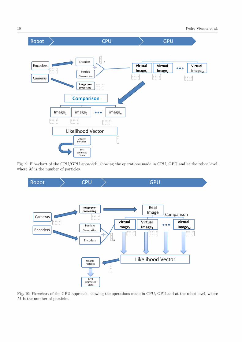
The Internal Model generates the virtual images on
the GPU memory. In order to compare the real and
virtual images we have two possibilities: (i) “download”
the generated images from the GPU to CPU memory
and compare them in CPU (we call this CPU/GPU
approach, see Fig. 9), or (ii) “upload” the real image
from CPU to GPU and compare them inside the GPU
(we call this GPU approach, see Fig. 10). In this work we
have implemented both approaches and compared them.
The latter (GPU approach) is able to achieve up to 3
times speed-up with respect to the former (CPU/GPU
approach).
We will describe in detail the proposed GPU ap-
proach, given its better efficiency. The CPU/GPU inter-
operation and the data structures that are shared and
sent between the two processing units can be seen in
Fig. 10. The CPU is used to communicate with the
robot receiving the data from the cameras and encoders.
It also manages the particle filter steps according to our
filtering approach. The main bulk of data generation
and evaluation is carried out at the GPU level by means
of parallel processing, using the OpenGL, OpenCV and
CUDA libraries. This interoperability will be explained
in Section 5.4.
In section 6.1 we compare the two approaches. We
will benchmark the time needed to generate the images
(frame rate) and how many particles we can evaluate in
one second (particle rate).
5.4 Interoperability between Libraries
The image processing routine necessary to compute the
particles likelihood is implemented in the GPU thanks
to the integration between Unityr, YARP, OpenGL,
OpenCV and CUDA libraries. We use the game engine
software in OpenGL mode launching it with the param-
eter -force-opengl. This feature is important for the
integration of all the libraries. We render the visible
scene in the cameras into a render texture structure
(RenderTexture class) with the format ARGBHalf and
get its pointer within the GPU memory, using the func-
tion GetNativeTexturePtr(). We initialize M render
textures and generate M different scenes according to
the M particles received from the particle filter. Ev-
ery texture has the information of both left and right
cameras.
We receive via YARP the images from the robot vi-
sion. In order to transfer the image data to an OpenGL
structure we use two functions: glBindTexture, to de-
fine the initialized texture as the current one and
glTexImage2D to import the data into the new struc-
ture using the information of the number of channels,
the alignment, and the widthStep. The format used in
OpenGL is GL_RGBA16F.
10 Pedro Vicente et al.
Fig. 9: Flowchart of the CPU/GPU approach, showing the operations made in CPU, GPU and at the robot level,
where M is the number of particles.
Fig. 10: Flowchart of the GPU approach, showing the operations made in CPU, GPU and at the robot level, where
M is the number of particles.

Robotic hand pose estimation based on stereo vision and GPU-enabled internal graphical simulation 11
In this phase, we have the concatenation of the real
images (left and right) and the M generated images
in OpenGL Texture2D. We exploit the CUDA pro-
gramming language from NVIDIA in order to wrap
the information from these OpenGL structures with
the visible scenes to the OpenCV GpuMat class. We
use the functions cudaGraphicsGLRegisterImage and
cudaGraphicsMapResources to access the OpenGL in-
formation by CUDA. The usage of the CUDA function
cudaBindTextureToArray() is now possible, transfer-
ring the image data from OpenGL texture to a CUDAtexture. Unmap and Unregister the OpenGL structures
in CUDA is an important step to guarantee a “clean”
GPU memory. The GPU-accelerated Computer Vision
module from the OpenCV library has some image pro-
cessing functions as well as matrices and per-element
operations. We have defined a CUDA kernel which takes
the information in a CUDA texture and writes the im-
age data in a GpuMat structure using the information
about the data pointer (GpuMat.data), the step size
(GpuMat.step) and the number of columns and rows
(GpuMat.cols, GpuMat.rows), where each thread is re-
sponsible for copying one-pixel information to this new
structure.
All the functions used to achieve the interoperability
between the different libraries are loaded through a
plugin written in C++.
6 Results
In this section we present the results of our experiments
illustrating the following aspects: i) comparison between
CPU/GPU and GPU implementation, in Section 6.1, ii)
comparison between the two observation models (i.e. sil-
houette segmentation vs edge extraction), in Section 6.2,
iii) general results of simultaneous online calibration and
pose estimation, with generalization to different areas of
the robot workspace, in Section 6.3 and iv) robustness
to non-uniform background, in Section 6.4.
The experiments consist of reaching movements towards
a target executed in the Unityr iCub simulator. To
simulate the presence of modeling errors (that we would
have on the real robot) we add artificial joint offsets in
the arm kinematic chain of the simulator; the offsets
have the same order of magnitude of the errors we typi-
cally encounter on the real robot. In the beginning of the
movement, the state that we want to estimate (i.e. the
joint offsets) is initialized from a Normal distribution
with zero mean and standard deviation σ = 5.0◦. As
soon as the robot hand enters the field of view of the
cameras, the particle filter starts estimating the hand
pose and updating the offsets state vector. In the end
of the movement, we evaluate the position and orienta-
tion errors of the estimated pose with respect to ground
truth.
6.1 Comparison between CPU/GPU and GPU
approaches
The GPU implementation of our computational frame-
work is one of the main focus of this paper. Here, we
compare two possible alternatives: i) CPU/GPU and
ii) GPU only. We use a computer equipped with an
Intelr Xeonr Processor W3503 at 2.4 GHz with 2 cores,
2 threads and a 4MB memory cache and an NVidia
GeForce GTX 750 with 512 CUDA Cores, a base clock
of 1020 MHz and 2048 MB of memory.
6.1.1 CPU/GPU methodology
In the CPU/GPU method we generate the virtual images
(either binary or edge images in accordance with the
observation model) on the GPU and “download” them
into the CPU to perform the comparison with the real
ones (see Fig. 9). The shortcoming of this methodologyis the latency between the CPU/GPU data transfer. The
data of the M generated images must be on the CPU in
order to perform the comparison. This method has ap-
plication in machines with a non-dedicated GPU, where
GPGPU programming is not possible. Some computers
have integrated graphics cards which do not support
CUDA or another GPU programming language. For this
reason, the study of this methodology is important as
an alternative to the full GPU-enabled approach.
6.1.2 GPU methodology
The GPU method is our proposed approach for ma-
chines with GPGPU abilities (see Fig. 10). We generate
and compare the virtual images inside the GPU using
the developed iCub internal model. We only upload the
stereo images from the real robot and download the
score/likelihood of each particle, thus saving computa-
tional effort due to the decreased data transfer between
CPU and GPU processing units. For this method a
CUDA compatible graphics card is needed in order to
perform the comparison between the observation and
the generated hypotheses. In Table 1 we can see the com-
putational efficiency of the different options in terms of
particle rate (number of particles evaluated per second)
and Frame rate (number of frames generated per second
on the visual simulator). We can see that the particle
rate is better when the image comparison is made at a
GPU level. This increasing speed can be justified due

12 Pedro Vicente et al.
to the fact that we do not have to copy all the M gen-
erated images (M - particles) into the CPU. The only
data transferred from the GPU to the CPU, as can be
seen in Fig. 10, is the likelihood vector computed by the
comparison between the uploaded real image and the
generated hypotheses. With these results, we can argue
that the GPU methodology presented before is the best
way to branch the algorithm in order to increase the
computational speed.
CPU/GPU GPUParticle Rate ∼ 100 ∼ 250Frame Rate ∼ 200 ∼ 600
Table 1: Comparison between the two different possible
methodologies in particle Rate (particles per second)
and frame Rate (images per second). We can see the
better performance using the GPU only.
6.2 Silhouette segmentation vs Edge extraction
We performed 10 different experiments in order to com-
pare the two proposed observation methods. We have
pre-defined the duration of the reaching movement to be
equal in every experience (90 frames). Each experiment
consists of performing the same reaching movement
twice; using either the silhouette or the edge approach
as the observation method. In each experiment the ini-
tial and final poses of the hand are different. All the
movements have the same duration (90 frames). In these
experiments, we have a uniformly colored background
to perform a better segmentation of the iCub hand in
the image. The silhouette approach requires this par-
ticular background in order to be able to perform a
segmentation of the robotic hand based on color. How-
ever, the edge extraction approach does not require this
uniformly colored background. In order to provide a fair
comparison between the two observation models, we use
the same environment for both.
In Fig. 11 it is shown the mean (bold line) and stan-
dard deviation (shaded-part) of the estimation errors
of the hand pose (position and orientation) (See Fig. 6)
obtained during the experiments. We compare both
methods to the non-Calibrated case (where we use only
the proprioception, i.e., β = 0). The convergence of both
methods and the reduced error compared to the Non-
Calibrated case show that both metrics can be applied
to this problem. Notably, the orientation error using the
edge extraction approach is lower compared with the
silhouette segmentation. The position error of the hand
has similar magnitudes in both cases.
FramesErrors 0 15 30 60 90Orient. Error [◦] 9.00 8.06 6.84 6.07 5.40Pos. Error [mm] 35.87 5.02 3.04 1.87 0.83
Table 2: The convergence of the pose estimation error
during one reaching movement.
Fig. 12: The estimated offsets reach a steady state after
about 30 frames (i.e. 30 iterations of the algorithm),
showing the online calibration of the robot model during
one reaching movement. (Best viewed in color)
6.3 Simultaneous pose estimation and robot calibration
In this section we illustrate the convergence proper-
ties of our algorithm using the GPU methodology (see
Section 6.1) with the edge extraction approach (see Sec-
tion 6.2). In Table 2 we show the estimation error of
the hand, position and orientation, at different frames
(i.e. iterations of the algorithm) in one reaching move-
ment. We can see that the orientation and position
errors significantly decrease during the motion. More-
over, in Fig. 12 we see the online offsets estimation
during the movement. The estimation reaches a steady
state after 30 frames. The calibration parameters in
this figure are the joint offsets that calibrate the robot
model, producing the hand pose estimation error that
is shown in Table 2. This is just one of the possible sets
of joint offsets that calibrate the model: as we explained
in Section 3.3, due to the redundancy of the robot arm
kinematics, other sets of offsets might be equally ef-
fective. Then, to better characterize the convergence
properties of our estimation approach, we perform 10
different reaching movements with different initial and
final hand poses. We use the same artificial offsets (β)
in all the movements. In Table 3 we show the mean and
standard deviation (Std Dev) of the hand pose estima-
tion error at the end of the reaching movements (Frame
90), comparing the online calibration and estimation
with the non-calibrated (without filter) case (β = 0).

Robotic hand pose estimation based on stereo vision and GPU-enabled internal graphical simulation 13
(a) Orientation Error
(b) Position Error
Fig. 11: Position and orientation errors during reaching movements in a uniformly colored background. Comparison
between the silhouette approach, the edges approach, and non-calibrated case. Thick lines represent the mean over
10 movements; the envelopes indicate the standard deviation. (Best viewed in color)
With Filter Without filterErrors Mean Std Dev Mean Std DevOrient. Error [◦] 6.87 2.44 12.34 1.73Pos. Error [mm] 7.81 6.37 41.27 2.74
Table 3: Mean and standard deviation of the final ori-
entation and position errors over several experiments
(different initial and final position).
6.3.1 Generalization and comparison with Cartesian
parametrization
In this section we compare the generalization of the
learned calibration parameters using two different types
of parametrization methods: one in the joint space (pro-
posed in this work) and other in the Cartesian space
(proposed in [12,14,15]). Our approach uses offsets in
the joints to compensate for calibration errors and es-
timate the hand pose (Eq. (3)). Another alternative,
as mentioned in Section 3, is to use a Cartesian error
transformation matrix (Eq. (5)). We can compute Tβ in
Eq. (5) as the error transformation matrix to be applied
to the nominal transformation (see Fig. 13).
In order to compare both methods, we introduce
a given set of artificial joint offsets in the model, and
then perform a reaching movement from an initial pose
toward a final pose; we call this the training movement.
During the movement, we estimate both the joint off-
sets β and the Cartesian error transformation matrix
according to:
Tβ = K (θ)−1K (θ + β) (21)
We retain the values of β and Tβ at the final (training)
pose. Then, we move the hand to six different testing
poses (see Fig. 14). At each pose we estimate the hand
pose using both the joint error parametrization β, and

14 Pedro Vicente et al.
Fig. 13: Cartesian error transformation matrix (Tβ)
between the real hand pose and the hand pose estimated
by using the robot model.
(a) Final training Pose
(b) Testing pose 1 (c) Testing pose 2 (d) Testing pose 3
(e) Testing pose 4 (f) Testing pose 5 (g) Testing pose 6
Fig. 14: Training in a trajectory with a final pose and
testing in different poses. The position and orientation
of the hand are very distinct. Here we show the left
images.
the Cartesian error parametrization Tβ , obtained dur-
ing the training movement, and compare them to ground
truth. In Table 4 we show the position and orientation
errors both in the training pose and in the different
testing poses. We compare the joint offsets parametriza-
tion with the Cartesian parametrization; the nominal
(non-calibrated) case is also shown for reference. It can
be seen that the joint offsets parametrization is better
in all the cases.
Fig. 15: Simulation of a non-uniform environment into
the left and right eyes of the iCub robot.
6.4 Simultaneous pose estimation and robot calibrationwith non-uniform background
We simulated a realistic virtual environment which re-
sults in a non-uniform visual background in the robot
images (see Fig. 15), to evaluate the robustness of our
method to more complex visual scenes. We use the robot
lab project from Unity Technologies that emulates a
laboratory environment which is similar to a realisticbackground. With such non-uniform visual background,
we exploit the edge extraction approach, since the sil-
houette approach is not very effective in this kind of
scenarios, where it is difficult to obtain a good segmen-
tation of the hand. We perform reaching movements,
similar to the ones presented in Section 6.3, with the
new background environment. In Fig. 16, we present
the performance of our approach comparing it to the
non-calibrated case. The computed errors at the end of
the movement (6.61◦ orientation error and 8.69 mm po-
sition error) have the same magnitude as in the uniform
background case (6.87◦ orientation error and 7.81 mm
position error, see Fig. 11) which indicates that our ap-
proach is robust to non-uniform environments. Moreover,
after 70 frames the filter converges to a good solution
with small variance.
7 Conclusions and future work
We presented a method to simultaneously estimate the
pose of the robot hand and to calibrate the robot model
using a GPU-enabled particle filter approach. Our so-
lution is marker-free and solely based on the robot em-
bedded sensors (stereo vision and proprioception). We
use an online estimation technique, and the GPU imple-
mentation allows us to perform the computation in real
time. Indeed, we show that we can increase the speed
of computation almost of a factor of three, with respect
to our previous hybrid CPU/GPU implementation.
We introduce a new approach for the visual estimation of
the hand pose, based on edges extraction, that provides
advantages with respect to silhouette segmentation. In-

Robotic hand pose estimation based on stereo vision and GPU-enabled internal graphical simulation 15
Orientation Error [◦] Position Error [mm]Joint offsets Cartesian Nominal Joint offsets Cartesian Nominal
Final training pose 5.42 5.42 12.28 4.16 4.16 42.05Testing pose 1 6.55 7.2 13.84 9.17 9.30 46.06Testing pose 2 5.53 11.66 13.210 8.14 31.69 41.71Testing pose 3 8.10 14.23 16.50 12.56 35.37 50.15Testing pose 4 7.70 14.3 16.32 13.31 30.97 44.34Testing pose 5 3.44 6.65 9.87 5.60 17.14 33.06Testing pose 6 5.90 6.45 12.30 3.82 4.33 34.96
Table 4: Estimation errors with the joint offsets parametrization, Cartesian parametrization and nominal model
(i.e. non-calibrated). The orientation and position errors are always smaller with the joint offsets parametrization.
(a) Orientation Error
(b) Position Error
Fig. 16: Position and orientations errors during reaching movement with a non-uniform background. Comparison
between edge-based approach and the uncalibrated case.
deed, we show the robustness of the edge extraction
approach to a non-uniform visual background, which
is similar to the environment present in a realistic sce-
nario.
Overall, we show that we can reduce the hand pose
estimation error considerably with respect to using the
nominal (non-calibrated) robot model (of about 2 times
in the hand orientation and 6 times in the hand posi-
tion). Moreover, we achieve good generalization when
calibrating the robot on a single reaching movement
and then testing the calibration in different areas of
the workspace. Therefore, the proposed method can be
used to correct the kinematic model of a robot during
reaching to improve, for instance, the task of grasping
an object. Despite no real world experiments are shown
in this manuscript, the proposed method and the devel-
oped software can be applied immediately to the real
robot.
Indeed, we plan to make real world experiments using ex-
ternal sensing to compute the ground-truth. Setting-up

16 Pedro Vicente et al.
a 3D sensor, for instance, the optitrack motion capture
[31], could be a solution to compute the hand pose in a
real scenario. We also plan to continue improving the
speed of the algorithm implementing the Particle Fil-
ter framework at the GPU architecture and using more
than one iCub model inside the game engine. If we could
generate more hypotheses in real time we could evaluate
more images from our robotic platform. The segmenta-
tion procedure for the silhouette-based approach can be
also improved to cope with more complex backgrounds.
This aspect could be achieved using a 3D vision sys-tem based on the stereo calibrated cameras in the iCub
eyeballs.
Acknowledgements This work was partially supported byFundacao para a Ciencia e Tecnologia (FCT) PLURIAN-UAL budget [UID/EEA/50009/2013] and the EU ProjectsPOETICON++ [FP7-ICT-288382] and LIMOMAN [PIEF-GA-2013-628315].
References
1. Ashmead, D., McCarty, M., Lucas, L., Belvedere, M.:Visual guidance in infants’ reaching toward suddenly dis-placed targets. Child Development 64, 1111–1127 (1993)
2. Birbach, O., Bauml, B., Frese, U.: Automatic and self-contained calibration of a multi-sensorial humanoid’s up-per body. In: Intl. Conf. on Robotics and Automation.Saint Paul, Minnesota, USA (2012)
3. Borgefors, G.: Distance transformations in digital images.Comput. Vision Graph. Image Process. 34(3), 344–371(1986)
4. Bradski, G.: The OpenCV Library. Dr. Dobb’s Journalof Software Tools (2000)
5. Canny, J.: A computational approach to edge detection.IEEE Transactions on Pattern Analysis and MachineIntelligence (1986)
6. Choi, C., Christensen, H.I.: 3d textureless object detectionand tracking: An edge-based approach. In: IROS, pp.3877–3884. IEEE (2012)
7. Ciliberto, C., Smeraldi, F., Natale, L., Metta, G.: Onlinemultiple instance learning applied to hand detection in ahumanoid robot. In: IEEE/RSJ International Conferenceon Intelligent Robots and Systems (IROS), pp. 1526–1532(2011)
8. Ciocarlie, M., Hsiao, K., Jones, E.G., Chitta, S., Rusu,R.B., Sucan, I.A.: Towards Reliable Grasping and Manipu-lation in Household Environments. In: Intl. Symposium onExperimental Robotics (ISER). New Delhi, India (2010)
9. Comport, A., Marchand, E., Pressigout, M., Chaumette,F.: Real-time markerless tracking for augmented reality:the virtual visual servoing framework. IEEE Transactionson Visualization and Computer Graphics 12(04), 615–628(2006)
10. Cox, T.F., Cox, M.: Multidimensional Scaling, SecondEdition, 2 edn. Chapman and Hall/CRC (2000)
11. Erol, A., Bebis, G., Nicolescu, M., Boyle, R.D., Twombly,X.: Vision-based hand pose estimation: A review. Com-puter Vision and Image Understanding 108, 52–73 (2007)
12. Fanello, S.R., Pattacini, U., Gori, I., Tikhanoff, V., Ran-dazzo, M., Roncone, A., Odone, F., Metta, G.: 3d stereo
estimation and fully automated learning of eye-hand coor-dination in humanoid robots. In: IEEE-RAS InternationalConference on Humanoid Robots (2014)
13. Fulkerson, B., Soatto, S.: Really quick shift: Image segmen-tation on a gpu. In: Workshop on Computer Vision usingGPUs, held with the European Conference on ComputerVision (2010)
14. Gratal, X., Romero, J., Bohg, J., Kragic, D.: Visual servo-ing on unknown objects. Mechatronics 22(4), 423 – 435(2012)
15. Gratal, X., Romero, J., Kragic, D.: Virtual visual servoingfor real-time robot pose estimation. In: Proc. of the 18thIFAC World Congress, pp. 9017–9022 (2011)
16. Hoffmann, M., Marques, H., Hernandez Arieta, A., Sum-ioka, H., Lungarella, M., Pfeifer, R.: Body schema inrobotics: A review. IEEE Transactions on AutonomousMental Development 2(4), 304–324 (2010)
17. Hol, J.D., Schon, T.B., Gustafsson, F.: On resampling al-gorithms for particle filters. In: IEEE Nonlinear StatisticalSignal Processing Workshop, pp. 79–82 (2006)
18. Jamone, L., Brandao, M., Natale, L., Hashimoto, K.,Sandini, G., Takanishi, A.: Autonomous online generationof a motor representation of the workspace for intelligentwhole-body reaching. Robotics and Autonomous Systems64(4), 556–567 (2014)
19. Jamone, L., Damas, B., Endo, N., Santos-Victor, J.,Takanishi, A.: Incremental development of multiple toolmodels for robotic reaching through autonomous explo-ration. PALADYN Journal of Behavioral Robotics 03(03),113–127 (2013)
20. Jamone, L., Damas, B., Santos-Victor, J., Takanishi, A.:Online learning of humanoid robot kinematics underswitching tools contexts. In: IEEE-RAS InternationalConference on Robotics and Automation (ICRA), pp.4811–4817 (2013)
21. Jamone, L., Natale, L., Nori, F., Metta, G., Sandini, G.:Autonomous online learning of reaching behavior in ahumanoid robot. International Journal of HumanoidRobotics 09(03), 1250,017 (2012)
22. Klingensmith, M., Galluzzo, T., Dellin, C., Kazemi, M.,Bagnell, J.A., Pollard, N.: Closed-loop servoing usingreal-time markerless arm tracking. In: IEEE-RAS Inter-national Conference on Robotics and Automation (ICRA)- Humanoids Workshop (2013)
23. Kording, K.P., Wolpert, D.M.: Bayesian integration insensorimotor learning. Nature 427, 244–247 (2004)
24. Lee, V.W., Kim, C., Chhugani, J., Deisher, M., Kim, D.,Nguyen, A.D., Satish, N., Smelyanskiy, M., Chennupaty,S., Hammarlund, P., Singhal, R., Dubey, P.: Debunkingthe 100X GPU vs. CPU Myth: An Evaluation of Through-put Computing on CPU and GPU. SIGARCH Comput.Archit. News 38(3), 451–460 (2010)
25. Leitner, J., Harding, S., Frank, M., Forster, A., Schmid-huber, J.: Humanoid learns to detect its own hands. In:IEEE Congress on Evolutionary Computation (CEC), pp.1411–1418 (2013)
26. Lockman, J.J., Ashmead, D.H., Bushnell, E.W.: The de-velopment of anticipatory hand orientation during infancy.Journal of Experimental Child Psychology 37, 176–186(1984)
27. Mathew, A., Cook, M.: The control of reaching movementsby young infants. Child Development 61, 1238–1257(1990)
28. Metta, G., Fitzpatrick, P., Natale, L.: YARP: Yet An-other Robot Platform. International Journal on AdvancedRobotics Systems (2006)

Robotic hand pose estimation based on stereo vision and GPU-enabled internal graphical simulation 17
29. Metta, G., Natale, L., Nori, F., Sandini, G., Vernon, D.,Fadiga, L., von Hofsten, C., Rosander, K., Lopes, M.,Santos-Victor, J., Bernardino, A., Montesano, L.: The icubhumanoid robot: an open-systems platform for researchin cognitive development. Neural Networks 23 (2010)
30. Moutinho, N., Brandao, M., Ferreira, R., Gaspar, J.,Bernardino, A., Takanishi, A., Santos-Victor, J.: Onlinecalibration of a humanoid robot head from relative en-coders, imu readings and visual data. In: IEEE/RSJInternational Conference on Intelligent Robots and Sys-tems (IROS), pp. 2070–2075 (2012)
31. NaturalPoint: Optitrack Motion Capture System. http:
//www.optitrack.com/. [Online; accessed 1-06-2015]32. Nickolls, J., Buck, I., Garland, M., Skadron, K.: Scalable
Parallel Programming with CUDA. Queue 6(2), 40–53(2008)
33. Oikonomidis, I., Kyriazis, N., Argyros, A.: Markerless andefficient 26-dof hand pose recovery. In: 10th Asian Con-ference on Computer Vision. Queenstown, New Zealand(2010)
34. Oikonomidis, I., Kyriazis, N., Argyros, A.: Efficient model-based 3d tracking of hand articulations using kinect. In:Proceedings of the British Machine Vision Conference,pp. 101.1–101.11. BMVA Press (2011)
35. Park, S.I., Ponce, S., Huang, J., Cao, Y., Quek, F.: Low-cost, high-speed computer vision using nvidia’s cuda archi-tecture. In: Applied Imagery Pattern Recognition Work-shop, 2008. AIPR ’08. 37th IEEE, pp. 1–7 (2008)
36. Pattacini, U.: Modular cartesian controllers for humanoidrobots: Design and implementation on the icub. Ph.D.thesis, Italian Institute of Technology (2011)
37. Periquito, D., Nascimento, J., Bernardino, A., Sequeira, J.:Vision-based hand pose estimation: A mixed bottom-upand top-down approach. In: 8th International Conferenceon Computer Vision Theory and Applications (VISAPP).Barcelona, Spain (2013)
38. Saxena, A., Driemeyer, J., Ng, A.Y.: Robotic graspingof novel objects using vision. Int. J. Rob. Res. 27(2),157–173 (2008)
39. Shreiner, D., Sellers, G., Kessenich, J.M., Licea-Kane,B.M.: OpenGL Programming Guide: The Official Guideto Learning OpenGL, Version 4.3, 8th edn. Addison-Wesley Professional (2013)
40. Sinha, S.N., Frahm, J.m., Pollefeys, M., Genc, Y.: GPU-based Video Feature Tracking and Matching. Tech. rep.(2006)
41. Thrun, S., Burgard, W., Fox, D.: Probabilistic Robotics(Intelligent Robotics and Autonomous Agents). The MITPress (2005)
42. Ulbrich, S., de Angulo, V., Asfour, T., Torras, C., Dill-mann, R.: Rapid learning of humanoid body schemas withkinematic bezier maps. In: IEEE-RAS International Con-ference on Humanoid Robots (Humanoids), pp. 431–438(2009)
43. Ulbrich, S., de Angulo, V.R., Asfour, T., Torras, C., Dill-mann, R.: General robot kinematics decomposition with-out intermediate markers. IEEE Trans. Neural Netw.Learning Syst. 23, 620–630 (2012)
44. Vicente, P., Ferreira, R., Jamone, L., Bernardino, A.:Eye-hand online adaptation during reaching tasks in ahumanoid robot. In: Joint IEEE International Conferenceson Development and Learning and Epigenetic Robotics(ICDL-Epirob), pp. 175–180 (2014)
45. Vicente, P., Ferreira, R., Jamone, L., Bernardino, A.:Gpu-enabled particle based optimization for robotic-handpose estimation and self-calibration. In: Robotica / IEEE
International Conference on Autonomous Robot Systemsand Competitions (Robotica/ICARSC) (2015)
46. Wang, R.Y., Popovic, J.: Real-time hand-tracking with acolor glove. ACM Transactions on Graphics 28(3) (2009)


![[25-30 Sep 2011] Surgical Tools Pose Estimation for a Multimodal HMI of a Surgical Robotic Assistant](https://static.fdocuments.us/doc/165x107/558b2f08d8b42ae97d8b4705/25-30-sep-2011-surgical-tools-pose-estimation-for-a-multimodal-hmi-of-a-surgical-robotic-assistant.jpg)