Robotic Fingerspelling Hand for Deaf-Blind Communication
142
6/4/2012 Cal Poly: San Luis Obispo | Mechanical Engineering Dept. ROBOTIC FINGERSPELLING HAND FOR DEAF-BLIND COMMUNICATION T E A M
Transcript of Robotic Fingerspelling Hand for Deaf-Blind Communication

P a g e | 0
Robotic Fingerspelling Hand | 2012
6/4/2012
Cal Poly: San Luis Obispo | Mechanical Engineering Dept.
ROBOTIC FINGERSPELLING HAND FOR DEAF-BLIND COMMUNICATION
T E A M

P a g e | 1
Robotic Fingerspelling Hand | 2012
Robotic Fingerspelling Hand
for Deaf-Blind Communication
June 6, 2012
Mechanical Engineering Department California Polytechnic State University
San Luis Obispo

P a g e | 2
Robotic Fingerspelling Hand | 2012
Capstone Project Partial fulfillment of the requirements for a
Bachelor of Science degree in Mechanical Engineering
Sponsor: The Smith-Kettlewell Eye Research Institute Rehabilitation Engineering Research Center for Blindness and Low Vision
Faculty Advisor: Dr. John R. Ridgely
Team Members:
Brian Fang [email protected] Colby Dixon [email protected] Trevor Wong [email protected]

P a g e | 3
Robotic Fingerspelling Hand | 2012
Acknowledgements
Dr. Deborah Gilden, Associate Director of The Smith-Kettlewell Eye
Research Institute for her sponsorship of this project as well as her words of encouragement throughout the year.
Dr. John Ridgely for his patience as well as all the engineering advice he offered throughout the year as our senior project advisor.
Jerry Vin for all his insight having worked on his iteration of the project for the past two years as a Master’s thesis.
Larry Coolidge for taking the time to assist in our rapid prototyping needs.
Cal Poly Machine Shops for use of their equipment.
Hobby Headquarters of Atascadero, CA for providing discounts on various parts, including servo motors.
ME 405/410 students for allowing us a portion of the Mechatronics lab to work in.

P a g e | 4
Robotic Fingerspelling Hand | 2012
Table of Contents
Chapter 1: Introduction……………………………………………………….. 1.1. Introduction 1.2. Capstone Project 1.3. Project Scope 1.4. Unit System 1.5. Terminology
Chapter 2: Background ……………………………………………………….
2.1. Dexter 2.2. Ralph 2.3. Cal Poly Senior Project 2008 2.4. Cal Poly Senior Project 2009 2.5. Cal Poly Master’s Thesis 2012
Chapter 3: Objective ...………………………………………………………..
3.1. Sponsor’s Requirements 3.2. Engineering Requirements
Chapter 4: Project Management …………………………………………….
4.1. Group/Individual Tasks Chapter 5: Milestones ………………………………………………………... Chapter 6: Design Approach ………………………………………………… Chapter 7: Design Development …………………………………………….
7.1. Unused Concepts 7.2. Used Concepts 7.3. Actuation Methods 7.4. Microcontroller 7.5. Programming 7.6. Hand Size
Chapter 8: Final Design ………………………………………………………
8.1. Motor Housing 8.2. Wrist Movement 8.3. Actuation 8.4. Finger Mechanism 8.5. Thumb Mechanism 8.6. Springs
6
10
14
15
17
20
21
40

P a g e | 5
Robotic Fingerspelling Hand | 2012
Chapter 9: Manufacturing …………………………………………………….
9.1. Rapid Prototyping the Hand 9.2. Construction of the Case 9.3. Other Manufacturing Options
Chapter 10: Testing …………………………………………………………... 10.1. Strength Tests 10.2. Fatigue Test 10.3. Heat Test 10.4. Future Tests Required
Chapter 11: Cost ……………………………………………………………… 11.1. Rapid Prototyping 11.2. Complete Design
Chapter 12: Results & Conclusion……………………………………………… 12.1. Results 12.2. Conclusion 12.3. Future Design
Appendix ……………………………………………………………………….
i. Sources ii. American Manual Alphabet iii. Bill of Materials iv. Quality Function Deployment Table v. Decision Matrices vi. Gantt Chart vii. Design Sequence Flowchart viii. Other Concepts ix. Solid Models x. Rapid Prototyping properties xi. Average electrical costs in California xii. Servo data sheets xiii. Servo shield information xiv. Program state transition diagrams and code xv. Torque calculation code xvi. Anthropometric Data excerpt xvii. Hand Shapes xviii. Installation tips
43
46
50
51
53

P a g e | 6
Robotic Fingerspelling Hand | 2012
Introduction Fluent communication is something that many people take for granted, but there is a
population that faces extreme difficulties with communication due to disabilities such as deaf-
blindness. Most adults with this condition have been diagnosed with Usher’s Syndrome. The typical
progression of Usher’s Syndrome starts with deafness at birth, and blindness occurring later in life.
This puts the affected individual into a position where they already know sign language but not
braille when they lose their sight. The term deaf-blind encompasses those who have completely lost
their hearing and sight as well as those who have only partially lost these senses. For people with
this condition, tactile sensation eventually becomes their main form of communication.
Various methods of tactile communication have been developed, such as the Braille
alphabet and the Tadoma method, but this project will focus on tactile finger-spelling. By feeling the
hand of a finger-speller, a deaf-blind person can read a message letter-by-letter using a learned
alphabet such as the American Sign Language alphabet. In this age of technology, a mechanical
hand that could take the place of a fingerspeller and connect to a computer would be of huge value
to someone who is deaf-blind. Currently there are no commercial mechanical fingerspelling hands.
The deaf-blind community still relies on a translator to communicate with people who do not know
sign language or fingerspelling. If there is a device that could fingerspell simply by typing message,
fluent communication between a deaf-blind individual and an individual with no fingerspelling
experience would achievable.
The Smith-Kettlewell Eye Research Institute in San Francisco, henceforth referred to as
SKERI, had great interest in this project and has gotten universities to try to make it a reality.
Several variations of a robotic fingerspelling hand have been initiated by SKERI, specifically by the
Rehabilitation Engineering Research Center and Dr. Deborah Gilden, who has asked our team to
approach this task from a new angle. The major stakeholders consist of SKERI, the deaf-blind
community, and our team, as the success of this project is important to our education as engineers.
Ultimately, the goal is to open the avenue of electronic communication to the fingerspelling deaf-
blind community. Our main goal is to create a robust, working robotic fingerspelling hand that can
fingerspell every letter in the American Sign Language alphabet. Other specifications that SKERI
require are that the hand is the size of an average person and that is it portable. Specifications that

P a g e | 7
Robotic Fingerspelling Hand | 2012
SKERI would like to see are: battery powered hand, hand size comparable to a small female, and
text to speech.
Capstone Project:
This project has been completed in partial fulfillment of the requirements for a Bachelor’s
Degree in Mechanical Engineering at California Polytechnic State University, San Luis Obispo. All
three of the team members are students in the Mechanical Engineering Department. Trevor Wong
and Colby Dixon will be leaving Cal Poly with their degrees upon completion of this project, and
Brian Fang will be staying to earn his Masters in Mechanical Engineering. The Capstone Project in
the Mechanical Engineering department is meant to be an exercise in teamwork and design,
starting from the brainstorming process and moving all the way through the manufacturing and
testing of a device. All Mechanical Engineering students go through this process with a team that
has been assembled by the department to complement one another.
The process is three quarters; the students are enrolled in ME 428 in the fall, ME 429 in the
winter, and ME 430 in the spring. The first two quarters involve assigned lab time with a project
advisor assigned by the department. In the case of this team, Dr. John Ridgely was assigned our
team due to his expertise in the area of mechatronics, or “Mechanical Electronics”. Throughout the
process, the students are constantly reminded that this is an exercise in the process of mechanical
design. Upon completion of the capstone project, it is the departments hope that the students will
be able to effectively work with a team to design and create a viable solution to some problem, as
well as to communicate effectively with the sponsor who has an interest in the project and supplies
the funding.
Project Scope:
Because so many attempts have been made to create a usable finger-spelling hand, we
made an attempt to build on past successes and failures rather than make the same mistakes. The
goal of this project has increasingly been to just make something work, even if it does not perfectly
mimic the movements of a human hand. We have made an attempt to describe our design to a
point where someone can easily apply what we have learned to a newer design that will address
some of the issues that we have had. A section of design recommendations is included at the end of
the report.

P a g e | 8
Robotic Fingerspelling Hand | 2012
Unit System:
The U.S. Customary Unit system was chosen for this project because it is the most commonly used unit for engineers in the Cal Poly Mechanical Engineering Department. Conversions were very minimal, as most of the specifications for components of the project were described in U.S. Customary, sometimes in addition to Metric units. The anthropometric tables used to determine hand size provide an example of the need for U.S. Customary units, as there are no listings of Metric units in the anthropometric data.
Terminology:
Team HandSpeak: Handspeak is a registered trademark as detailed at handspeak.com. The contents of the website are also copyrighted. The name “Team HandSpeak” is used solely for the purpose of the Mechanical Engineering Capstone project at California Polytechnic State University, San Luis Obispo in the time period of September 2011 through June 2012. The logo for Team HandSpeak is significantly different than the logo for handspeak.com. In the event of any content from handspeak.com being used in Team HandSpeak’s final report, the proper citation will be added as per handspeak.com’s specifications. HandSpeak is not to be used as a brand name or product name in any future revisions of the final design created by Team HandSpeak.
Deaf-blindess: There are various ways to write the term “deaf-blind”. For this report, both “deaf” and “blind” will be fully lowercase unless beginning a sentence or title. Someone who is deaf-blind is considered to have impaired vision and hearing, it does not necessarily mean that they are both legally blind and deaf.
Cal Poly: This capstone project is completed for a bachelor’s degree at California Polytechnic State University, San Luis Obispo. The name of the college is commonly referred to as simply “Cal Poly”, and will be referred to as such for the rest of the report.
Proximal-Medial-Distal Phalanges: The segments of the fingers that are connected by joints are known as “phalanges”. The term “proximal” describes the phalange closest to the hand, “medial” describes the middle phalange, and “distal” describes the tips of the fingers.
Cables: Many different actuating lines were used in the development of the hand. All of them had the characteristic of being small, flexible, able to carry tension, and easily tied at the ends. For this report, items with these characteristics are referred to as the “cables” that transfer power from the motors to the mechanisms. A more descriptive term for our final choice would be “coated wire rope”, but we feel that “cable” is sufficient.
Servos: This term requires the most explanation because it is the least defined. Technically, a “servomechanism” is any mechanical device that has some sort of automatic feedback that tunes the performance of the device. “Servomechanism” is often shortened to “servo”, but can still apply

P a g e | 9
Robotic Fingerspelling Hand | 2012
to any device such as a valve or piston. The term “servo” in our report refers to small Hobby Servo Motors that contain a potentiometer and feedback circuit within the body of the device. This makes the motors much easier to control than attaching our own encoders for example, which would require many more connections and electronics.
Torsion Springs: Truly, a torsion spring is one that stores energy via torsion in the material. The springs used in the hand are referred to as “torsion springs” because they create and resist torque about the pivots. The metal itself is actually storing energy via bending as the coils get tighter.

P a g e | 10
Robotic Fingerspelling Hand | 2012
Background The first attempt at creating a fingerspelling hand was patented in 1978 by the Southwest
Research Institute, henceforth referred to as SWRI. It served to be a proof of concept but failed to
make all the necessary hand-shapes and operate in a fluid manner. Since then there have been five
notable attempts, along with five projects at Cal Poly, three of which are completed and two of
which are currently in progress. Due to the history of engineering on this topic, our team has
chosen to focus our background research on these previous hands and will forgo extensive research
into other far more complicated robotic and prosthetic hands. The following paragraphs will
provide a brief background of the four hands that we benchmarked against and why.
Figure 1. Dexter
DEXTER:
The first hand we will focus on has been dubbed “Dexter” by SKERI. It was built by a team of
Stanford Mechanical Engineering Students in 1985. Dexter was much improved over the hand built
by SWRI and formed all the letters of the alphabet but was extremely bulky and required
compressed air to drive the pneumatic actuators. Although the drive system was impractical and
bulky, the hand itself was quite successful for the level of simplicity in its design. The whole hand
had seven pneumatic actuators. Each finger was actuated by a single pneumatic with a linear spring
to provide some resistance and return. The pneumatic pulled four metal cables. Three of the cables
were used to bend each section of the finger and the last cable was used to straighten the finger.
For the index finger, there was a second pneumatic that twisted the finger so that it could form the
letter R. The thumb was controlled by two pneumatics actuators. The first one controlled the

P a g e | 11
Robotic Fingerspelling Hand | 2012
bending of the thumb across the hand. The second one controlled the thumbs movement to and
away from the hand. Since the hand was made of metal, it is very sturdy and robust. As other
attempts have been bogged down by too many complications, we felt that Dexter was studying for
inspiration. The cable system proved to be very effective in bending the fingers and its overall
design is very robust. Two subsequent Dexter designs later came about and met with mild success.
Figure 2. Ralph
Ralph:
The most successful of the designs seems to be RALPH, for Robotic ALPHabet. This hand was
built in 1994 by the Rehabilitation Research and Development department of the Veterans Affairs.
RALPH fixed many of the problems of the Dexter hands, but still wasn’t quite robust or attractive
enough to be picked up by any commercial companies. RALPH was also only half a hand as it only
had the fingers, no forearm and no wrist. The hand is also very short, which made it hard to read as
it is in an unnatural position for the reader. It was actuated with DC servo motors. The fingers were
made with mechanical linkages rather than wire. RALPH connected to computers using a serial
connection, RS232. The interface with the user was done through a computer. While all the control
was done on the microcontroller in the hand.

P a g e | 12
Robotic Fingerspelling Hand | 2012
Figure 3. Cal Poly Senior Project #1
Cal Poly Senior Project #1:
In January 2008, a senior project team at Cal Poly took on this challenge, accomplishing a
remarkable amount of research and development in their short time frame of six months. They built
a working hand that met many of the requirements for the project. Unfortunately, they ran into a
serious problem when they found that their choice of actuators overheated and limited the use
time of the hand. They chose to build the hand out of aluminum. This resulted in a hand that was
bulky and not lifelike enough to be successful. There is much to learn from their design process and
trial and error.
Figure 4. Cal Poly Senior Project #2
Cal Poly Senior Project #2:
We are also benchmarking against the hand of a Cal Poly interdisciplinary team. Of the
many things that we can learn from this hand is the performance of hobby servos and
manufacturing. The hand had issues with durability, and it broke in several places, but at one time it
was a working device. Each joint was connected with a mechanical linkage, so only one servo was
needed to completely bend a finger. This design does not allow for independent motion of the
distal, intermediate phalanges to the proximal phalange.

P a g e | 13
Robotic Fingerspelling Hand | 2012
Figure 5. Jerry Vin's Graduate Thesis Hand
Jerry Vin:
Another hand is the work of Jerry Vin, a graduate student at Cal Poly. Jerry’s project is
currently in progress and he has expressed interest in offering his experiences to our team. His
design uses eleven DC brushless motors and two DC hobby servos. The index finger is controlled by
three motors. The motors rotate to pull on a cable that bends or straightens the joints. This distal
phalange is linked to the intermediate phalange with a mechanical linkage. As the intermediate-
proximal joint bends, the distal-intermediate joint bends with it. The last motor pulls on a cable that
moves the finger to the side so that it can make the letter V. The ring and pinky finger are controlled
by one motor. The middle finger is actuated exactly like the index finger, except it does not have a
third motor to move it side to side. They are the same as the middle finger, except they do not need
independent control for the intermediate-proximal and proximal-metacarpal joints, so those cables
are threaded through one motor. The thumb is controlled by four motors. One motor was used to
control the distal-proximal joint and another to control the proximal-metacarpal joint. The third
motor is used to move the thumb across the hand. The last motor is to control the thumbs
movement to and away from the hand. As we are somewhat designing in parallel, it seems useful to
benchmark against his work and collaborate with thoughts and positive criticisms.
P a g e | 14
Robotic Fingerspelling Hand | 2012
Objective Our project was to build a device that would be able to communicate with a deaf-blind
person through fingerspelling. The main goal of the project is to have the device form all 26 letters
in the English alphabet and sequence them into words. The next major goal is to make the system
as robust as possible. This means that it will work reliably and smoothly throughout its lifetime. The
device should be portable, as well as allow the user the option of different orientations, such as
horizontal and vertical. The operation of the device will be driven by a computer. This will require a
substantial amount of coding. Few other smaller goals are that the device should not be too loud,
look realistic and easy to fix. The product should be safe. Safety issues include: features ensuring
the hand will not crush a user’s hand, prevention of exposed wires shocking the user, etc.
Sponsor’s Requirements:
• The hand should be able to form all 26 letters of the American Manual Alphabet.
• The hand should be lifelike.
• The hand should be portable and be able to be read in different orientations.
• The hand should be the size of an average adult or smaller.
• The hand should not have any heating issues where the reader would get burned from
touching the hand.
• The hand should be able to form letters at minimum a speed of one letter per second.
• The hand should be able to form letters based off of user input.
• The hand should cost under $1000. Ideally in the $500 range.
Based on the sponsors’ requirements, we came up with the following categories of engineering
targets:
• Internal Temperature – Sustainable heat dispersion
• External Temperature – Temperature on the exterior of the hand
• Input / Output – Ability to spell letters after being typed
• USB or serial port – The type interface with the computer
• Number of interfaces – What programs will be used to connect the computer and hand
• Delay between letters – The time delay between forming letters

P a g e | 15
Robotic Fingerspelling Hand | 2012
• Delay between words – The time delay after finishing spelling a word
• Number of external controls – Number of buttons or switches on the exterior of the hand
• Ability to form letters – The accuracy and ability to form letters
• Ease of Use – How intuitive is the device and the length of the learning curve
• Double letter indication
• Noise Level
• Weight
• Time to attach/detach – The amount of time it will take to detach from a base
• Battery Life
• Usage Voltage – Amount of voltage used to operate the device
• Length of Hand
• Glove – Will a glove be used
• Horizontal - Can the device be used while it is parallel to the floor
• Vertical - Can the device be used while standing upright
• Lap held – Can the device be used while lying on someone’s lap
• To scale – how to scale the fingers relative to each other and palm
• Interior accessibility – The ease of getting to the interior of the device
• Production cost
• Price
• Life-time
• Force to induce
• Force to withstand
Through the process of making a Quality Function Deployment (QFD), we could see what
engineering requirements we should focus on. We weighted customer’s requirements based off
what we felt was most important. From there we put a number from 1-9. A “1” meant that the
engineering requirement was not really relevant to requirement and a “9” for very relevant to
requirement. With the requirements all weighted, we could see that the two most important
engineering requirements we should focus on was the ease of use and weight. The two lowest rated
categories were visual appeal and noise level.

P a g e | 16
Robotic Fingerspelling Hand | 2012
At the bottom of the QFD, we have a set of targets we aimed to meet for each of the
categories listed above. Along with our targets, we benchmarked previous projects on their
performance in each category. Some of the categories were measured with a Yes/No. Yes was used
if the previous projects were able to meet the category requirement and No if it was not able too.
There is also a +, √, - system used to rate categories. A "+" means that the project greatly exceeds
our desired target. A “√” means that the project can meet our target. A "–" means that the project
does not meet our target or cannot meet our target. A "?" meant that weren’t able to obtain
enough information to rate the project properly.
P a g e | 17
Robotic Fingerspelling Hand | 2012
Project Management
In the early stages of development, each member of the team was equally involved in all
aspects of the project. This included background research, preliminary analysis, and production of
conceptual models. Upon choosing the best model to follow through to a final design, each
member’s focus shifted to different tasks in order to accomplish more in the same amount of time.
This is described below.
Brian:
Originally, each member was to design a portion of the hand, Brian’s being the palm.
However, once it was realized that a shield was necessary to power all of the servos, his attention
shifted to designing and building a custom shield. Brian was also in charge of developing the master
program that would be programmed onto the Arduino.
Colby:
Colby was initially in charge of designing the fingers and the base connection to the hand.
He would later continue where Brian left off on designing the palm. This task took a considerable
amount of time as Colby made a conscious effort to make the hand appear more realistic.
Trevor:
Trevor was tasked with designing the thumb. The thumb is the only digit that was simplified
by fixing a joint position and yet was to still be used to form all the letters of the alphabet. Trevor
was also in charge of making the user_task code which is used by the master program, as well as
the code used to tune the servo s/finger positions.
Though the tasks were divided, all the members of our group were able to assist one
another. For example, the programming reached a point where nothing could be verified until the
hand was made, so the team collaborated on the design. All of the members also took part in part
procurement, machining, and assembling of the project.
A summary of the major tasks can be seen in the table below, as well as a list of milestones
which follow. For a visual aide, see the Gantt chart in the appendix.

P a g e | 18
Robotic Fingerspelling Hand | 2012
Table 1. Group/Individual Tasks
Tasks Brian Colby Trevor Base design x Hand design x x x Machining/Rapid prototyping x x x Mechatronics x x Progress documentation x x Shield design x Testing/Evaluating x x x

P a g e | 19
Robotic Fingerspelling Hand | 2012
Milestones
1. Conceptual design review
2. Critical Design Review
3. Working finger model, open/close motion
4. Working thumb model, open/close/rotate
5. Project Update
6. Computer-to-hand recognition of alphabet
7. Palm and back of hand casing , hand assembled
8. Wrist movement and arm completed
9. Adjustable orientation/detachable base assembled
10. Final SKERI meeting
11. Design Expo
12. Industry Expo for SKERI
December 5th 2011
February 3rd 2012
February 20th 2012
March 26th 2012
March 26th 2012
April 19th 2012
April 30th 2012
May 15th 2012
May 15th 2012
May 21st 2012
May 31st 2012
June 28th 2012

P a g e | 20
Robotic Fingerspelling Hand | 2012
Design Approach Our project is somewhat unusual in that each component of the hand can be developed
largely independent of the others. For example, the method by which we curl the individual fingers
has little to do with the type of actuator we use, because almost all of our concepts for the curl can
be driven by any type of spinning shaft. The one exception to this is the idea of linear actuators in
the fingers that act directly on the joint. With this in mind, we assumed a mostly bottom-up design
process in which we made decision matrices for each component. We split the hand into three
major systems: the wrist, the fingers, and the thumb. To further divide the components, each of
these groups has various subsystems that need to be decided on.
After brainstorming many different ideas, we weighed the pros and cons of each idea,
allowing us to eliminate all but a few core concepts. All of these concepts then went into a group of
decision matrices. As an example, four matrices were made for the fingers: the actuators, the drive
mechanism, the curl mechanism, and the range of movement. Some of the matrices may seem
repetitive, such as the drive mechanism for the fingers and for the thumb, but the weights of the
criteria differ, which changes the output. After building our matrices, we can then look at what
combinations will work the best. Each individual component will be tested and prototyped, and
then the whole thing will be brought together.
P a g e | 21
Robotic Fingerspelling Hand | 2012
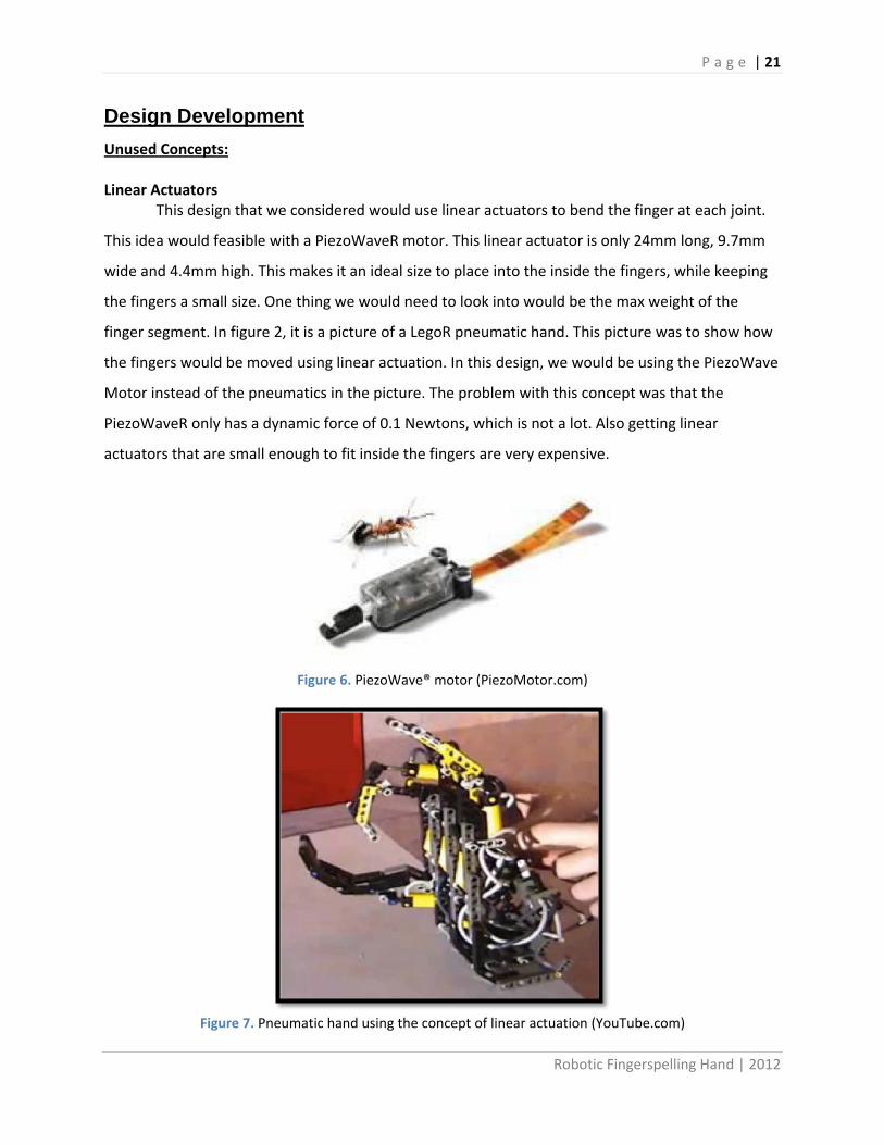
Design Development Unused Concepts: Linear Actuators
This design that we considered would use linear actuators to bend the finger at each joint.
This idea would feasible with a PiezoWaveR motor. This linear actuator is only 24mm long, 9.7mm
wide and 4.4mm high. This makes it an ideal size to place into the inside the fingers, while keeping
the fingers a small size. One thing we would need to look into would be the max weight of the
finger segment. In figure 2, it is a picture of a LegoR pneumatic hand. This picture was to show how
the fingers would be moved using linear actuation. In this design, we would be using the PiezoWave
Motor instead of the pneumatics in the picture. The problem with this concept was that the
PiezoWaveR only has a dynamic force of 0.1 Newtons, which is not a lot. Also getting linear
actuators that are small enough to fit inside the fingers are very expensive.
Figure 6. PiezoWave® motor (PiezoMotor.com)
Figure 7. Pneumatic hand using the concept of linear actuation (YouTube.com)

P a g e | 22
Robotic Fingerspelling Hand | 2012
Flexible Tubing Our fourth concept is the simplest design. It would use a rubber or flexible material along
with one pull string. There are grooves cut at where joints would be to allow the finger to bend
properly. Linear springs could be inserted at the grooves to provide for a faster return to neutral
position. The major problem with this design is that it would be hard to control the movement of
the fingers because the slots would require precise material removal.
Figure 8. Hand with triangular cuts shown
Figure 9. Curled Hand

P a g e | 23
Robotic Fingerspelling Hand | 2012
Used Concepts:
Digit Design
Our first model was inspired by DEXTER. We tried to recreate the mechanism of wrapping
cables around joints and pulling on them like puppet strings. This model proved the concept, but
after more testing we found that just a pulley method to be insufficient for our needs.
Figure 10. Dexter pulley system Top left: bent finger Top right: straight finger Bottom: Finger with pulley
system and platform
Our next design used pulleys to curl the finger. The pulleys would have a 1:1 ratio so that
the second knuckle will rotate with the same angle as the first. This was been incorporated into our
final design to bend the distal knuckle with the medial knuckle. This eliminates many components
as there is no need for a drive or return cable at the knuckle.

P a g e | 24
Robotic Fingerspelling Hand | 2012
Figure 11. Pulley curl system Top: curled finger Bottom: straight finger
This mock-up displays many concepts, while also serving as a test platform. It will allow us
to test many different components such as the cables, motors, controller board, springs and finger
segments.

P a g e | 25
Robotic Fingerspelling Hand | 2012
Figure 12. Test platform with bent finger
Inspired by the cable / housing system used on bicycles, we chose to use Bowden Cables for
power transmission from the motors to the fingers, thumb and wrist. Using this type of system
allows us to mount the motors in the forearm of the device, which will avoid considerable size
constraints in the palm. With the housing passing through the wrist, the hand will be able to twist
relative to the forearm without interrupting the control of the digits. Another advantage is the ease
of adjustment for the cable length. As on bicycles, we can incorporate a threaded barrel adjuster
that will lengthen or shorten the housing length, effectively collecting or releasing cable. Small
Bowden Cable systems are sold for use in robotics such as remote controlled helicopters. We also
have the option of buying the cable (or wire rope) individually and matching it with appropriately
sized tubing. This would require some trial and error.

P a g e | 26
Robotic Fingerspelling Hand | 2012
Figure 13. Bowden cable system
By incorporating torsion springs directly into the knuckles, we avoid the need for return cables. This
cuts our number of cables in half and greatly simplifies the design.
Figure 14. Knuckle return springs

P a g e | 27
Robotic Fingerspelling Hand | 2012
Initially, we thought that we would use pulleys to rotate the knuckles, but after prototyping,
a better method was found. In this design the cable will be connected to a rod near the bottom of
the finger that will provide a moment arm around the joint. It allows a much larger moment arm
than a pulley would, and doesn’t require any tedious installation. Another advantage is that the
shaft for the knuckle does not need to be fixed to the desired phalange, again simplifying design.
Figure 15. Finger drive method
P a g e | 28
Robotic Fingerspelling Hand | 2012
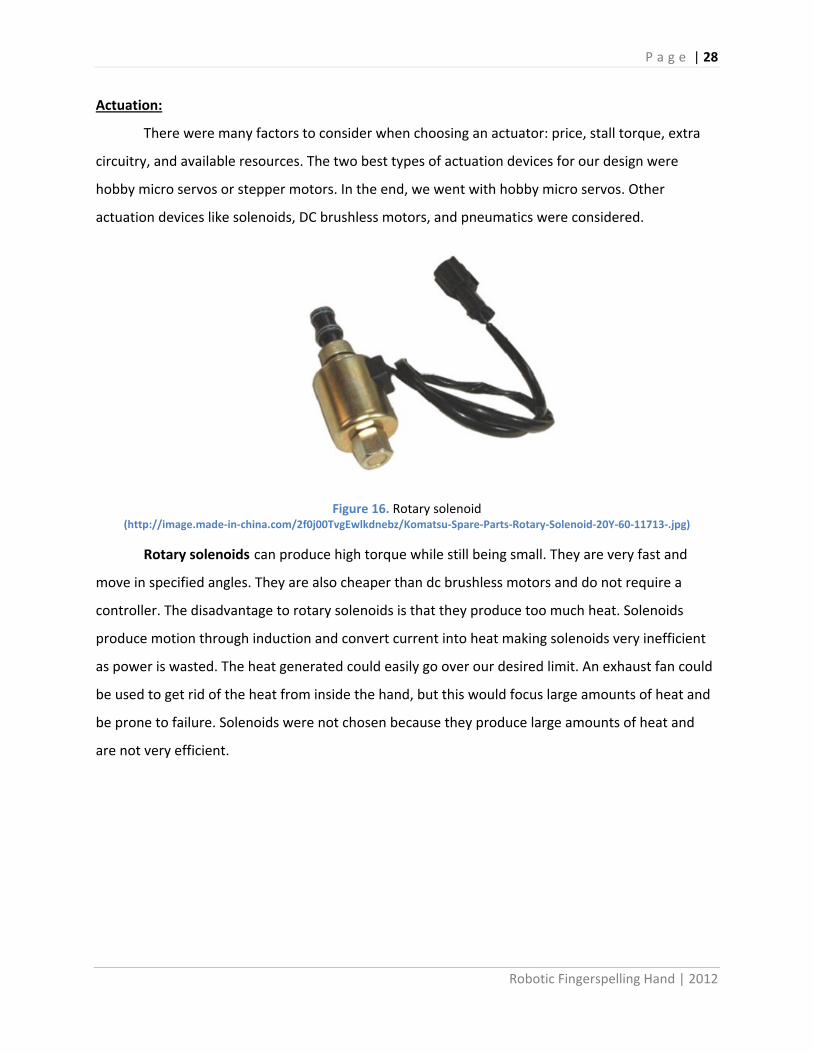
Actuation:
There were many factors to consider when choosing an actuator: price, stall torque, extra
circuitry, and available resources. The two best types of actuation devices for our design were
hobby micro servos or stepper motors. In the end, we went with hobby micro servos. Other
actuation devices like solenoids, DC brushless motors, and pneumatics were considered.
Figure 16. Rotary solenoid
(http://image.made-in-china.com/2f0j00TvgEwlkdnebz/Komatsu-Spare-Parts-Rotary-Solenoid-20Y-60-11713-.jpg)
Rotary solenoids can produce high torque while still being small. They are very fast and
move in specified angles. They are also cheaper than dc brushless motors and do not require a
controller. The disadvantage to rotary solenoids is that they produce too much heat. Solenoids
produce motion through induction and convert current into heat making solenoids very inefficient
as power is wasted. The heat generated could easily go over our desired limit. An exhaust fan could
be used to get rid of the heat from inside the hand, but this would focus large amounts of heat and
be prone to failure. Solenoids were not chosen because they produce large amounts of heat and
are not very efficient.

P a g e | 29
Robotic Fingerspelling Hand | 2012
Figure 17. Maxon Dc brushless motor with encoder
(http://maxonmotorusa.files.wordpress.com/2011/10/ec16_new-sterilizable-and-non-ster.jpg)
DC brushless motors are very durable and have a long life time. They are very efficient,
which allows the hand to operate longer with a battery pack. The biggest DC brushless motors are
expensive and much more expensive when they are very small. They also require motor controllers,
which is extra cost, and a software controller to get exact positioning for the motor. DC brushless
motors were not chosen because the high initial cost and the need of more complicated software
and hardware to control them.
Figure 18. Tolomatic pneumatic cylinders
(http://www.motioncontrolproducts.com/pageimages/erdactuator_large.png)
Pneumatics was considered for a more comprehensive development, even though the
sponsor made it clear that this method was not desirable. The benefit of pneumatics and hydraulics
is that they could be small enough to fit inside the finger and actuate each section. But small
pneumatics and hydraulics are expensive. Pneumatics and hydraulics also require controllers and a

P a g e | 30
Robotic Fingerspelling Hand | 2012
fluid supply, which adds to the cost and weight of the device. Pneumatics was not chosen at the
request of the sponsor.
Figure 19. Stepper motor
(http://www.designworldonline.com/uploads/ImageGallery/step-motor.jpg)
Stepper motors were a good candidate for actuating the hand. They are very accurate due
to the fact that a full rotation is divided into many steps, like an encoder. There would be no need
to write a software controller as stepper motors operate in open control loop. This allows for us to
just send a voltage and the stepper would rotate to desired position. The downsides to stepper
motors are that they tend to be heavy and can lose efficiency if any of the steps are skipped during
a rotation. It is sometimes necessary for stepper motors to have additional hardware in the form of
motor controller. Alone, these controllers would add approximately $120 to the cost of the project,
bringing the total cost of the motors to half of our desired budget.
Figure 20. Hitec HS-625MG Hobby Servo used in project

P a g e | 31
Robotic Fingerspelling Hand | 2012
Hobby micro servos were our final selection. Hobby servos are small, cheap, and can
provide large amounts of torque. Since hobby servos have a built in gear train, a micro servo can
easily provide over 30 ounce-in of torque. Hobby micro servos cost about 13-15 dollars each, so our
cost would only be around $150. This makes servos one of the cheapest actuation devices. The
biggest advantage to going with hobby servos is that they do not require an auxiliary position
controller, which greatly saves cost. Servos have a built in position controller. This makes coding to
control the servos very simple. Servos are also very light weight. Ten servos would weigh no more
than 100 grams. The disadvantages of servos are that they do not have long life and may need to be
replaced frequently. The main reason we chose servos were that they are cheap, light, and very
compact.

P a g e | 32
Robotic Fingerspelling Hand | 2012
Microcontroller: With 10 servos, we need 10 digital pins. This means we need at least ten I/O pins. We have
two options for our circuit board. One option is to design a custom board; we would have a circuit
board that does only what we need and doesn’t have extra unnecessary features. The other option
would be to buy a premade board. Designing a custom board may actually be a cheaper alternative.
With a custom board we can choose a microprocessor that has enough pins for our application and
a few extra for expandability and unplanned additions. Going this route would require a large
amount of time. Designing the board would take 2-3 days. After designing the board, the design
would need to be sent to a board making company. The board would take 1-2 weeks to be made.
After finishing the board, we would need to spend some time to make sure the board is working
properly before we can even start programming.
We decided to buy a premade board. We chose to work with the Arduino platform. The
Arduino Uno is the most common model, with 14 digital pins and 6 analog pins. The other models
like the Arduino Mega have more pins than we require for our application and are more expensive.
Though, they could be easily swapped in place of the Uno for expandability in the future. The price
of the Arduino Uno is around $20-$30. Arduino also has a large amount of C++ libraries for
servomotors. By choosing to go with the Arduino, it allowed us to spend more time on building and
testing our hand.
Figure 21. Arduino Uno board
Since we could not control and power up all 11 servos with the Arduino, we needed a servo
shield that could power the board while the Arduino could control them. All available servo shields
could at most control 2-4 servos. We needed to control 11 servos. We decided to design a servo

P a g e | 33
Robotic Fingerspelling Hand | 2012
shield. We used Eagle PCB to draw the schematic and the board layout. With the board layout
done, we submitted it to a PCB manufacturer, Dorkbot. Their website is
http://dorkbotpdx.org/wiki/pcb_order.
Figure 22. Left PCB without components. Right PCB with all components
For our application, each servo needed to be provided with 6V and 500mA of current to
run at full speed. This means we need a power supply or AC adapter that can supply our system
with 6V and 5.5A. We decided that 4A was enough for the system since servos require 500mA
only when it is moving and does not require the full 500mA when holding a position. When
looking for AC adapters, 6V 4A AC adapters were not common, and were hard to find. So we
found a 12V 4A AC adapter. This AC adapter is much more common. So for our board we had to
look for a 2.5mmID X 5mmOD power plug. From there, we had to regulate the 12V down to 6V
so that the servos could use them. When looking for way to regulate high current, we had a
choice between going with a high current voltage regulator or a two transistor circuit. The high
current voltage regulators that we found had a thermal resistance of 3°C/W. If we go the two
transistor route, the PNP transistor taking all the current would only have a thermal resistance
of 2°C/W. This would make keeping the transistor from overheating and blowing up easier.

P a g e | 34
Robotic Fingerspelling Hand | 2012
Figure 23. PnP transistor and voltage regulator setup to allow for high current voltage regulation
We chose a BDX54C for our PNP transistor and a LM317T for the voltage regulator. The
PNP transistor acts as a pass transistor allowing all the current to pass through it while the
voltage regulator regulates the voltage. The R3 resistor is there to allow some current to go to
the voltage regulator so that it will regulate properly. Using the circuit above, we use a ratio of R1
and R2 to regulator 12V down to around 6V. The resistors we used were 230 and 820, which were
available in our mechatronics room. This gave us an output voltage of 5.74V. With the main part of
our circuit done, it was just connecting pins to allow us to put pin headers to make attaching servos
to the board easier. The servos connected to pins 2-12 of the Arduino board. Pin 13 has a 5k pull
down resistor attached to it to allow us to use a button to trigger a demo mode in the program.
Another button is attached to the reset and ground pin to allow the user to reset the Arduino from
outside the box.
When the board was completely assembled and tested, we noticed that the PNP would heat
up too much and that the heat sink for it was not enough. We tried to fix that by doing two things.
First we added a fan that would blow directly at the heat sink. Second we changed from a 12V 4A
AC adapters to a 9V 4A one. This decreases the power the PNP transistor needs to dissipate by
12W, which is about 25°C decrease in the temperature increase. But we still have a heat issue.
The transistor’s junction temperature is 150°C. With the fan blowing and using a 9V 4A AC
adapter, the transistor can get up to 95°C theoretically. With our infrared heat gun, we were
able to see around how high the temperature got. The results of this testing can be seen in the
testing section of the report. We are still working on a way to use our larger heat sink. We could
not attach it directly to the transistor because of space restrictions. Before when we were
testing with the board outside of the case, we had the larger heat sink attached. With the large

P a g e | 35
Robotic Fingerspelling Hand | 2012
heat sink attached, we could run for a much longer time without worrying too much about
overheating.

P a g e | 36
Robotic Fingerspelling Hand | 2012
Programming: The coding for the project is done in C++, one of the most common programming languages
available. It is written in a very modular fashion, which allows for the program to be modified by
others. If there is a need to change the actuation code or user interface, it can be easily done
without affecting the overall code. With a computer, it uses a terminal program to talk with the
Arduino. The user is able to type in sentences or words into the textbox, or have the hand perform
real time movements using the real time box. The Arduino manufacturers include many libraries in
C++ which is very convenient for us. One of the library files is for servomotors which we used to
actuate the servos.
The main file consists of a constructor and an infinite loop, which runs the program using
cooperative multi-tasking, which makes the runtime more efficient. There are two classes that are
run inside the main file, master_task and user_task. The main file will be supported by other files
which it will use to run, including a user class which takes user input from the computer, and master
class that overlooks everything.
The user_task is in charge of getting user input. User will only accept letters and instruction
keys, if any other key is pressed, nothing will happen. The instructions are: “1” to attach servos, “0”
to detach servos, “[space]“ to delay between words, “-“ or “_” to increase delay between letters or
decrease spelling speed, and “+” or “=” to decrease delay between letters or increase spelling
speed.
User_task has 3 states. The first state waits for a character to be entered. After user gets a
character, it goes to state 2. In state 2, it checks to see if the character is a valid input. If it is a valid
input it will set valid to true, which tells master that a valid character has been gotten. After state 2,
user stays in state 3 until master is done and is ready to get a new character.
The master_task class is the overseer of this entire program. It determines what to do when
something is pressed. After the input of each letter from the user_task, master_task will get the
servo positions that correspond with input letter by referencing a large look-up table. The lookup
table will consist of an integer array of servo positions from 0-180°. These positions are determined
through trial and error during the testing stages of the project. There are #defines for different
angles for each finger. This makes it easier to see if the look up table is correct and makes tuning
the hand a much simpler job. Instead of having to go to each letter and changing the servo angle, it
P a g e | 37
Robotic Fingerspelling Hand | 2012
can be done by changing the servo angle in the #define. Another part of the master is to make sure
that the fingers are not interfering with each other when moving.
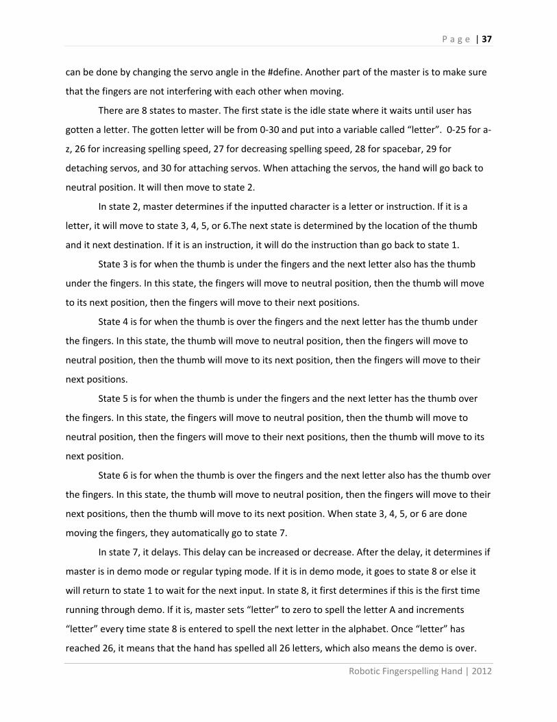
There are 8 states to master. The first state is the idle state where it waits until user has
gotten a letter. The gotten letter will be from 0-30 and put into a variable called “letter”. 0-25 for a-
z, 26 for increasing spelling speed, 27 for decreasing spelling speed, 28 for spacebar, 29 for
detaching servos, and 30 for attaching servos. When attaching the servos, the hand will go back to
neutral position. It will then move to state 2.
In state 2, master determines if the inputted character is a letter or instruction. If it is a
letter, it will move to state 3, 4, 5, or 6.The next state is determined by the location of the thumb
and it next destination. If it is an instruction, it will do the instruction than go back to state 1.
State 3 is for when the thumb is under the fingers and the next letter also has the thumb
under the fingers. In this state, the fingers will move to neutral position, then the thumb will move
to its next position, then the fingers will move to their next positions.
State 4 is for when the thumb is over the fingers and the next letter has the thumb under
the fingers. In this state, the thumb will move to neutral position, then the fingers will move to
neutral position, then the thumb will move to its next position, then the fingers will move to their
next positions.
State 5 is for when the thumb is under the fingers and the next letter has the thumb over
the fingers. In this state, the fingers will move to neutral position, then the thumb will move to
neutral position, then the fingers will move to their next positions, then the thumb will move to its
next position.
State 6 is for when the thumb is over the fingers and the next letter also has the thumb over
the fingers. In this state, the thumb will move to neutral position, then the fingers will move to their
next positions, then the thumb will move to its next position. When state 3, 4, 5, or 6 are done
moving the fingers, they automatically go to state 7.
In state 7, it delays. This delay can be increased or decrease. After the delay, it determines if
master is in demo mode or regular typing mode. If it is in demo mode, it goes to state 8 or else it
will return to state 1 to wait for the next input. In state 8, it first determines if this is the first time
running through demo. If it is, master sets “letter” to zero to spell the letter A and increments
“letter” every time state 8 is entered to spell the next letter in the alphabet. Once “letter” has
reached 26, it means that the hand has spelled all 26 letters, which also means the demo is over.

P a g e | 38
Robotic Fingerspelling Hand | 2012
Master will then detach the servos and delay so the PNP transistor can cool down. After 20 seconds,
the hand will reattach the servo and go to state 1 so it is available to be used again.
We have also included a tuning program for the fingers. This tuning program allows the user
to adjust the finger locations in case of slack in the cable or to change the accent of the hand. The
servos start at a default angle of 140°. In the tuning program, you press “1” to decrease the angle
and “2” is to increase the angle of the servo that controls the knuckle movement. You press “3” to
decrease the angle and “4” to increase the angle of the servo that controls the medial joint. The
program only allows the tuning to go from 20-170°. This is to prevent the user from going to 180° or
0°, where the servo PWM messes up and tries to go beyond its limit. That will cause the servo to fry.
When you want to change fingers to tune, you press “+” or “=” to go to the next finger, and “-“or
“_” to go back to the previous finger. The order that the tuning goes by is thumb, index finger,
middle finger, ring finger, pinky, and wrist. If you press the next finger button when it is at wrist, it
will loop back to the thumb, and if you press the previous finger button when it is at thumb, it will
loop to wrist. You can also detach the servos with the “s” key, and attach the servos with the “g”
key.

P a g e | 39
Robotic Fingerspelling Hand | 2012
Hand Size:
The size of the hand needed to be comparable to that of an adult. To do this, data was obtained from
the 1988 Hand Anthropometry of U.S. Army Personnel, and has been summarized in inches in the tables
below. The data corresponds to the average measurements listed of women, along with their standard
deviations. The dimensioning of the fingerspelling hand will closely adhere to the average values, and
will be adjusted accordingly, within one standard deviation, to account for all the interior components.
This didn’t present too much of a problem as the majority of the larger components are located
elsewhere in the design.
Table 2. Relevant digit measurements from 1988 Anthropometric study
Digit 1 +/-
(inches) Digit 2 +/-
(inches) Digit 3 +/-
(inches) Digit 4 +/-
(inches) Digit 5 +/-
(inches) Thumb Index Middle Ring Pinky Length 2.5 0.19 2.74 0.18 3.04 0.2 2.84 0.2 2.3 0.18 to wrist 4.95 0.34 6.69 0.37 7.02 0.39 6.65 0.38 5.73 0.37 Breadth 0.81 0.05 0.78 0.05 0.76 0.05 0.72 0.05 0.65 0.04 circumference 2.48 0.1 2.41 0.08 2.41 0.07 2.26 0.08 1.99 0.07 Distal 1.21 0.1 1 0.08 1 0.03 1.03 0.09 0.93 0.08 Medial -- -- 0.83 0.09 0.99 0.11 0.9 0.1 0.64 0.09 proximal 0.76 0.11 2.22 0.21 1.96 0.17 1.91 0.13 1.49 0.12
Table 3. Relevant hand/forearm measurements from 1988 Anthropometric study
Inches +/-
hand length 7.11 0.39 hand circumference 7.34 0.34 palm length 3.97 0.22 hand breadth 3.13 0.15 wrist breadth 2.24 0.14 wrist circumference 5.96 0.27 wrist center-of-grip 2.61 0.19 elbow to hand 17.46 0.93 elbow to wrist 10.35 0.61 forearm circumference 10 0.59

P a g e | 40
Robotic Fingerspelling Hand | 2012
Final Design
Motor Housing:
To hold components such as the motors and the microcontroller, a rectangular case was made from 0.220 inch clear acrylic sheets. Acrylic was chosen to display the inner workings of the motors, as well as for its workability with the laser cutting machine on campus. See the manufacturing section for a further description of this process.
The case is sized so that an average-sized person will be able to rest their elbow on the table while feeling the hand, but the case also allows for other orientations. If preferred, the case can be turned around and the user’s wrist can rest on the case. Also, the case can be turned onto its side to read the hand in a horizontal position.
Wrist Movement:
The wrist mechanism allowed for major simplifications over previous hands. Many of the letters of the alphabet are formed by lowering a vertical wrist into a more horizontal position. Also, “J” and “Z” are considered dynamic letters and are formed with scoop and wiggle of the wrist, respectively. Because the wrist has to support the entire hand, it has been a weak spot in many past designs, with the tilt causing the most problems. Tilting the hand to the side applies a large moment to the wrist area, while also throwing off the balance of the entire device. For these reasons, we chose to design our wrist to spin only about a vertical axis by 180°.
This twist about the vertical axis provides us with a degree of freedom that is underutilized in the common ASL alphabet. With the presumption that the deaf-blind are adaptable enough to learn variations on the alphabet, the single twist of the wrist allows for 26 distinct movements and has the ability to replace the tilt of the wrist in letters such as “G” and “H”. This can be thought of as the hands “accent”. Initially, an explanation of the wrist movement and the affected letters should be created using the most recognizable letters for the deaf-blind user.
The hand is supported by an aluminum shaft that was machined into the desired shape and size. The most significant aspect of the wrist shaft is the “D” shaped ends, which sink in to hand on one end, and the wrist servo attachment on the other. This shape acts as a key in the shaft to transfer rotational power. The hand is also screwed onto the shaft, but this is simply to stop it from falling off. Most of the torque should be transmitted through the “D” shape and not through shear in the screw. The lower end of the shaft is not screwed to the servo because its position is fixed by casing for the mechanism. The shaft was designed with a larger diameter section in the middle that sits between 2 flanged, sealed ball bearings. Not only does this hold the bearings into their position in the case, but also holds the wrist shaft in after the top to the case has been screwed in. The 2 bearing, stepped shaft design removes all axial force from the servo, which is not designed to such axial loads.

P a g e | 41
Robotic Fingerspelling Hand | 2012
Problems: To fully utilize the movement of the wrist, it needs to turn by a complete 180°. Unfortunately, the servo that is turning the wrist cannot be driven a full 180° without the likelihood of damage, so the wrist is restricted to move approximately 150°. For future designs, it is recommended to choose a servo that is designed to move more that the common 180°, such as a “sail winch” servo.
Actuation:
In actuating the movements of the hand, our design mimics the human body in that the “muscles”, or servos in our case, are housed remotely and “tendons” transfer mechanical power to the moving parts. A great example of this is readily seen in the way that bicycle brakes and derailleurs are actuated. The system consists of a length of housing that is maintained as some fixed length while flexible cable is allowed to slide through. The cable is fixed to the actuator on one end, and the mechanism on the other. When building the concept models, bicycle cable housing was used but the diameter was far too large for the application inside the hand, considering that the hand needs 11 independent lengths of these housings.
After experimenting with different cables and housings, the products chosen for the final design were found at the local hobby store. The housings are antennae coverings for remote controlled cars, and the cable is nylon-coated stainless steel cable used for actuating the flaps of remote controlled airplanes. The cables are crimped using common bead wire crimps that can be found at most arts and crafts stores. The crimps should be large enough that the cable can loop and pass twice through the crimp.
Problems: The 1/8th inch housing is not flexible enough to allow for totally fluid movement of the wrist. The servo used to twist the wrist is strong enough to overcome this binding of the cable housings, but future designs should strive to find a type of cable housing with more flexibility.
When crimping the nylon-coated cable, the crimps have the tendency to strip the coating from the cable. When this happens, the cable will lose its tension and the exposed metal strands can be dangerous.
Finger Mechanism:
By using springs to return the fingers to a straight position, there is only one actuation cable per joint, and it is simply anchored to the phalange which is desired to move. Past designs had problems with trying to use a continuous cable loop from the motor to the finger that would bend and straighten the finger. The use of springs greatly simplifies this system and allows the hand to be in a natural position even when it is not hooked up to a motor. The difficulty in the design chosen for the fingers is getting enough of a moment arm on the pivot. Because the fingers are so small, there is not much room to pass the cables by the pivot, so they end up with a small moment arm.

P a g e | 42
Robotic Fingerspelling Hand | 2012
The distal and medial phalanges are kinematically tied, and the distal will move any time that the medial moves. This not only mimics the way that a human finger moves, but also eliminates the need for a third actuator on each finger. The movement is achieved by using a short cable anchored to the proximal phalange on one side and the distal phalange on the other and uses a cross pulley mechanism.
Thumb Mechanism:
The thumb has two degrees of freedom, with the outermost joint fixed. With the tip of the thumb bent at a fixed angle, the hand still makes sufficient and intelligible movements and avoids the need for tip actuation. The base of the thumb has the ability to rotate on an axis in plane with the palm and perpendicular to the wrist. This allows for the necessary movements to form letters such as “O”. Due to the positioning of this system, it made more sense to run a true “pull-pull” system as opposed to a single pull with a spring return such as with the fingers. To make the thumb sweep across the palm, the same method was used as with the fingers, but to achieve the letters such as “L”, the thumb needs to sweep 90° from vertical in both directions. Where the fingers use 180° springs that are bent to 90°, the thumb uses a 270° spring that rotates to 90°. This allows the thumb to be held out away from the hand in its neutral position, yet still bend all the way into the palm when actuated.
Springs:
Several different size springs were used in the hand. Initial calculations found that a spring constant of approximately 1 in-lb would be sufficient to hold the fingers in a straight position even if the hand was horizontal and provide the user with enough feedback to let the hand move. With the extremely light weight of the final design, and the small size of the fingers, it was determined that each joint would have a different spring constant, descending from 1 lb-in at the base knuckle, to ¼ lb-in at the tip joint. This is because of the larger moment on the base knuckle. Unfortunately, there is a slight problem with the spring at the base knuckle getting squeezed at a full bend, which causes the finger to stick a little bit. This problem has not caused much trouble because the base knuckle almost never needs to bend all the way to create our shapes.
To reduce slop in the joints, the springs were plastically deformed to rest neutrally at an angle of a little more than 180°. Although they are considered to be 180° springs by the manufacturer, they all rest at some angle slightly less than that. This was an easy solution and made more a more solid hand design.

P a g e | 43
Robotic Fingerspelling Hand | 2012
Manufacturing
The manufacturing of the hand was done largely by the 3D printer (ObJet 250) at Cal Poly.
This machine has the ability to take a solid model file from a program such as SolidWorks and create
that model from a gel called EDEN FullCure 720. The process is fast and is referred to as “rapid
prototyping” for obvious reasons. For example, each finger took close to two and a half hours to
print, which is much quicker than many other manufacturing methods would have been. The
fingers, thumb, palm, and hand were all made using this process. A few of the material properties
are listed in Table 2, while the rest can be found in the appendix.
Table 4. Partial property list of FullCure 720
Objet FullCure 720 Eden
Tensile Strength 8744 psi
Density 0.0426 lb/in^3
Modulus of Elasticity 416150 psi
Hardness 81 M
To be printed, the SolidWorks part was saved as a .STL file which could be read by the rapid
prototyping software. The parts were then positioned on a virtual tray. This part of the process took
some time because the orientation of the part determined how much filler material would need to
be used. Every layer put down by the printer has to lay on top of another layer, so to create voids in
the part the printer would use the filler, or “support” material as a base for the next layer. Our final
print ended up using about 300g of FullCure and 250g of support material. Small modifications were
made to the rapid prototyped parts with a drill and a Dremel tool to provide more clearance for
moving parts.
The case built from the sheets of acrylic was cut from 18” X 24” sheets of acrylic that were cut into pieces using the laser cutter in the Mustang 60 machine shop at Cal Poly. For the most part, these pieces were good to go as soon as they left the machine, but some pieces had to have their edges sanded down to provide for a more flush perpendicular fit. This is because the laser tends to create a slight slope to the edge of the sheet when it cuts through. Any modifications to the acrylic proved to be difficult, and the second version of the case that was created was done so with less need for modification. Drilling through the acrylic is doable but tricky. The material will melt and has a tendency to build up on the drill bit and cause problems for the next hole to be drilled. This can be somewhat remedied by passing the clogged drill bit through a block of wood. This will re-melt the

P a g e | 44
Robotic Fingerspelling Hand | 2012
material and push it to the un-bladed portion of the drill bit, where it can remain or be pulled off of the end. Another tactic is to use pliers to break off the hardened acrylic, but this method is less consistent in its success. A 2-56 tap was used to make threaded holes for the servos to mount into.
Most of the case was assembles using Weld-On #3 Acrylic solvent cement. Unable to find this adhesive at any hardware store, we eventually found it at a glass store. This adhesive works in much the same way as welding materials together, because it liquefies the material and forms a strong bond as long as the surfaces are flush. Care must be taken when working with the adhesive because any of the liquid that drops will mar the acrylic surface. Overall the adhesive worked well and produced clean and strong junctions.
Some components of the case need to be removable such as the top bank of servos. For this we used metal L-brackets to hold things together temporarily. JB Weld was used to fix nuts to the back of the brackets so that the screws could be driven directly into the case without needing access to the inside. On the first version of the case, all 4 sides were permanently fixed with adhesive. This made it very difficult to get down inside to the case, so the front wall of the second case was made to be removable, greatly easing the installation of all the components.
Although this project required relatively little time in the machine shop, some parts were
still manufactured using traditional machines such as the lathe and mill. The wrist shaft required the
most machining. First the shaft was cut to length using the chop-saw with a special blade for cutting
aluminum, and then a lathe was used to face the ends and turn the entire length enough to give it a
nice finish. While leaving the center section untouched, both ends were turned down to a diameter
small enough to pass through the bearings. Then the mill was used to create the “D” flats. Finally
the wrist mount hole was drilled and trapped. Somewhat more tricky to machine was the pins for
the finger joints. Each of these had to be grooved to allow for the e-clips to clip to the side. A
custom grooving tool was made from an old broken parting tool to make the grooves the right size
and depth.
In the future, this hand could be made through injection molding. This way, the hand can be
cheap and affordable as parts will only cost cents to make. But to use injection molding, the
demand for the hand would have to be in the hundreds of thousands. Another solution is to the
hand made with CNC. This solution is more reasonable for production numbers in the hundreds.
The last solution is to have the design and 3d drawings open to the public, so this hand could be
personally made through a rapid prototyping company if this hand is not available commercially.
Using a computer numerical control (CNC) machine is another possible way to create our
parts. CNC can make the parts with high tolerances. We would have blocks of plastic and place it in
P a g e | 45
Robotic Fingerspelling Hand | 2012
the machine. Then based off our computer aided design (CAD) files, it would drill and mill a part for
us. We choose not to go with this process because the machine shop on campus was closed due to
budget cuts. This makes it inconvenient to make parts when we need them. But this is a viable
option for small production amounts of the hand.

P a g e | 46
Robotic Fingerspelling Hand | 2012
Testing
The testing that has been done so far consists of our conceptual models. We have learned a
great deal through tinkering with items easily obtained from the local hobby store. Because of this,
we felt much more confident in our final design than if everything had just been done on paper. We
built a test stand that initially was able to hold a finger or thumb. It later expanded to hold the
entire hand and came into much use in the time leading to our final design. Various servos were set
up and tested on this platform.
Figure 24. Strength test. Cables tied to weights at one end and tied to components on the other end
Strength tests were performed on the cables and fingers. For the cables, we had two, a
weaker cable and our current cable. To test the cables, we tied weights at one end and lifted the
weights with the cable. For the weaker cable, it snapped at 10 lbs. Our current cables snapped at
30lbs. A similar thing was done for the joints in the finger. We tied weights at one end of the cable
and tied the other end to a particular joint we wanted to test. All rapid prototype parts were able to
withstand more force than the cable. Through all this strength testing, we could conclude that the
first thing to fail in our system would be the cables in normal use.

P a g e | 47
Robotic Fingerspelling Hand | 2012
Figure 25. Finger in fatigue test setup hitting the bump switch
Fatigue tests were performed on the fingers, servos, and cables. The comprehensive test
had the assembled prototype monitored while form the letters of the alphabet continuously in a
loop for several hours or until a component breaks. The fingers went through a similar test in which
they looped between fully open and fully closed while hitting a bump switch counter for every
repetition. This test was only done once and it was done using the weaker cables. The weaker cable
was able to last 2700 runs. If the weaker cables were able to perform that well, we expect the
current cables to last at least 3 times longer.
One of our test plans involved the testing of the forces created by the digit. While the digit
was in the test stand, a linear spring scale was placed at a measured distance from the joint in
question. Measuring the forces for the purpose of satisfying our requirements, as well as check the
torque of the motors and springs against the manufacturers’ specifications. In particular, we
intended to find out how much external force is necessary to move the hand out of position, and
the grip strength of the hand in order to make sure the hand grip would not crush the user’s hands.
At the same time, we could make sure that the hand would still be strong enough to overcome the
weight of the user’s hands in order to form letters. A multimeter was simultaneously monitoring
the current drawn by the motor. This test was never fully done. When we attempted, the cables
snapped before we could get a reading, and we ran this test again with the stronger cables. We did
hook up a multimeter to see how much current the servos drew when actuating. The servos drew
about 5oo-800mA when moving and used 300-400mA when holding the finger in full curl position.

P a g e | 48
Robotic Fingerspelling Hand | 2012
After examining previous models that Cal Poly students have produced, we noticed that
many servo horns had sheared, rendering many components useless. Those projects were done
using the standard nylon horns that came with the servos. An alternative to nylon horns is to use
aluminum servo hubs. A fatigue test that will be performed simultaneously with the finger tests, as
the servo hub will be pulling the cable back and forth. This test was never done due to time
restraints. We used the stock nylon horns instead of getting aluminum horns. The stock nylon horns
proved to be strong enough for the application as not one has failed in all our testing.
Figure 26. Infrared heat gun used to check temperature of different components
In addition to fatigue tests, we also planned to perform heat tests. Heat will be generated
by the electronic components. Each servo will require at least 400mA of current to produce its rated
torque, and any leftover current will dissipate into heat. Therefore we used an infrared
thermometer to monitor the hand. Ideally, the highest temperature wouldn’t be much greater than
70°F, which is considered comfortable to human touch. Since the board is enclosed in the case,
there isn’t a likely chance of someone getting burned by it.
The biggest problem that we encountered with our design was overheating of one of our
transistors. This problem is described in detail in the Electrical Design section of the report. The
results of our heat testing showed a remarkable drop in the temperature of the transistor when
using the 9V power supply (circles) instead of the 12V power supply (triangles). It was encouraging
to see a physical effect of our theoretical predictions about heat generation. In the test, there are 3
different states that the servos can be in. When attached (green), the controller is holding the

P a g e | 49
Robotic Fingerspelling Hand | 2012
75
80
85
90
95
100
105
0 100 200 300 400 500 600 700
Tem
pera
ture
(°F)
Time (sec)
detached
running
attached
9V detached
9V running
9V detached
servos in a particular position but they are unmoving. When detached (yellow), the controller is not
sending a signal to the servos but it is plugged in to the power supply. The active state (red) is when
letters are being formed every 2 seconds and therefore the servos are moving often.
We planned to perform a noise test, but we do not currently have any instruments to
measure decibels, so we intend to compare the noise relative to other common devices or
appliances. Ideally, the hand will produce less than 80dB, which is the same amount of noise
produced by a telephone dial tone. The hand does not get very loud. The hand makes the loudest
noise when moving to position and makes a small humming noise when holding positions. Overall
the hand is not that noisy and the sponsors had no comments on the noise.
When the time comes where we have a complete working prototype, it’d be used to
interact with people in the deaf-blind community to test the readability of the hand-shapes. We had
hoped to perform this testing well before the final report was due in order to make the hand
positions as accurate as possible. This test was never done. We could never get in touch with
someone in the deaf-blind community or someone who uses fingerspelling on a daily basis.
Hopefully at the RESNA conference, feedback on the letters and the hand will be relayed back to us.
Figure 27. Compiled transistor temperature readings of heat tests

P a g e | 50
Robotic Fingerspelling Hand | 2012
Cost
Rapid Prototyping: For rapid prototyping, service providers will charge anywhere between five to ten dollars
per cubic inch of the FullCure 720 material. However, the printing software used metric
measurements and so for convenience, we determined the material cost using the FullCure density
of 1.189 g/cm3 and its common rate of $0.50/cm3. In addition to that, providers will also charge
operating fees which would include the amount of electricity used and labor for cleaning the parts.
As of 2011, the average cost of electricity for a medium sized company was about $0.16/kWh. Also,
the Objet 250 printer that was used consumes 1.5kW, so we determined that the rate of electricity
to be $0.24/hr. In Table 3, we provide cost estimation for the material.
Table 5. FullCure 720 cost estimation
Rate Usage Cost
Material $0.50/cm3 300 g $ 126.16 Electricity $0.24/hr 15.5 hr $ 3.72 Cleaning $20/hr 0.333 hr $ 6.67 Total $ 136.55
Complete Design:
Below is summary of major components and the total cost of producing one unit. A full bill
of materials separated by each component can be viewed in the appendix. Note that the cost of the
hand differs from the table above due to the addition of parts; springs, washers, pins, etc.
Table 6. Total cost of one unit
Component Cost Hand $ 159.90 Electronics $ 74.92 Case $ 81.14 Servos & Cables $ 398.75 Total $ 714.71

P a g e | 51
Robotic Fingerspelling Hand | 2012
Results & Conclusion
The two cases that were constructed yielded different results for the hand. The first case
was made prior to the final presentation at The Smith-Kettlewell Eye Research Institute. At the time
of the presentation, the case was not yet implemented, but it was desired by the sponsors to
include more holes for ventilation as there were problems with the heat sink and transistor
overheating. Until a replacement power adapter was delivered, work continued on the case in short
intervals to keep the electronics moderately cool. When the hand was tuned and fully assembled in
the first case, all but the dynamic letters of the alphabet were able to be displayed. There was not
enough room for the housing to move freely if the wrist were to turn.
Although, the hand was able to account for double letters without having to return to a
neutral position and would wiggle one or several digits depending on what letter was being
repeated. This was accomplished due to the logical statements placed in the code. Though, the
code didn’t account for double letters of “L” and “Y” as the logic was based on the position of the
thumb; in our code, both letters have the thumb in a zero position, which bypasses the conditional
statements looking to see whether the thumb or fingers need to move from the previous letter. The
major accomplishment of this design, however, was that it was able to demo the entire alphabet in
less than four seconds by pressing a button on the side of the case. From the terminal, the hand
was able to take letter input in real time, as well as spell out typed words at speeds specified by the
user.
Having come that far, we felt that we would be able to construct a second case that would
account for the ventilation and cable housing problem. By that time, we had also received an
adapter using less voltage which we hoped would address some of the overheating problems. The
end result was that the transistor is still overheating, though not as fast, and also that the speed of
forming letters has dropped to being slightly faster than one letter a second. The hand now
occasionally twitches when forming consecutive letters. We’re not entirely sure what the root
cause of this problem is, but it is being looked into.
Looking back at the requirements listed by our sponsor, we feel that we were or would be
able to accomplish most of them. With a little more time, the wrist could be programmed to do the
dynamic letters, making the hand able to form all the letters of alphabet. We believe the hand is the

P a g e | 52
Robotic Fingerspelling Hand | 2012
smallest and the most lifelike of all the attempts made previously by Cal Poly students. The hand
itself exerts no heat, it can be placed in different positions, and is controllable based off user input.
While we weren’t able to reach the target cost for the project, we feel that the cost is reasonable
for something that can’t be made cheaper through mass production.
Future Designs: If work is to be continued based off this design, here are some of the areas in which it could be improved:
• The first case design didn’t allow enough room for the housing to move during the actuation of the wrist. Construction of the 2nd case took longer than expected and prevented the actual implementation of the wrist actuation for dynamic letters.
• Double letter indication for the letters “L” and “Y” isn’t included. Though, no word in the English language uses consecutive “Y”s.
• The letter “V” was simplified by not splitting the index and middle fingers. However, this may not be considered entirely acceptable.
• A housing that is more flexible and that will not increase friction is needed. The current housing is too still and makes assembling difficult
• Bending of the wrist is necessary to better distinguish between letters.
• A better way to disperse heat from the heat sink is needed. The power adapter was switched from 12V to 9V to reduce heat at the cost of letter formation speed.
• A rechargeable battery would make the design more portable.
• The clear case design was intended to show off the electronic actuation of the hand. Transitioning the case to a forearm design would also make the hand more portable.

P a g e | 53
Robotic Fingerspelling Hand | 2012
Appendix
1. Sources 2. American Manual Alphabet 3. Bill of Materials 4. Quality Function Deployment 5. Decision Matrices 6. Gantt Chart 7. Design Sequence flowchart 8. Other concepts 9. Solid models 10. Rapid Prototyping properties 11. Average electrical costs in California 12. Servo data sheets 13. Servo shield schematics & layout 14. Servo shield components and data sheets 15. Program state transition diagrams and code 16. Torque calculation code 17. Anthropometric Data Excerpt 18. Hand Shapes 19. Installation tips

P a g e | 54
Robotic Fingerspelling Hand | 2012
Bibliography Greiner, Thomas M. (1991) Hand Anthropometry of U.S. Army Personnel. Berliner, Fung, Hansen, & Harris. (2009). Robotic Finger-Spelling Hand Final Report. Garcia, M. L. (2009). Design, Control, and Programming of A Robotic Finger-Spelling Hand. Jaffe, D. L. (1994). Evolution of Mechanical Finger-Spelling Hands for People Who Are Deaf- Blind. Steever, A., Torjesen, L., & Cheung, C. K. (2008). Robotic Finger-Spelling Hand for Tactile Communication with the Deaf-Blind. Tepe, A. (2008). Robotic Finger-Spelling Hand for the Aid of the Deaf and Blind.

P a g e | 55
Robotic Fingerspelling Hand | 2012
American Manual Alphabet
http://upload.wikimedia.org/wikipedia/en/thumb/6/6f/Aslfingerspellalpha.png/220px-Aslfingerspellalpha.png

P a g e | 56
Robotic Fingerspelling Hand | 2012
Bill of Materials
QTY Part No. ITEM COST 20 #10-24 Fasteners $ 2.00
Case
20 #10-24 x 1/2" Phillips pan head machine screw $ 1.80 4 #2-56 x 1/4" Phillips pan head machine screw $ 0.36
10 1" x 1/2" Zinc Corner Brace $ 9.90 1 1/2" Vinyl Bumpers (9 pk) $ 2.99 1 MC-21 Acrylic Sheet (Clear) 18"x24"x.22" $ 18.49 1 8974K113 Aluminum 6061 round 3/4 OD, 12" $ 4.27
10 Black RC Antenna Housing 1/8" OD, 14" $ 4.99 2 6384K363 Steel Ball Bearing, Flanged for 1/2" Shaft $ 21.34 1 Weld-On: Acrylic $ 15.00 1 JFCT2S1.5G #2 Silver plated crimps (100 pk) $ 3.24 Servos &
cables
48 2-56 x 1/2 Flat Phillips Machine Screws $ 1.92 1 8930T16 5ft Nylon Coated SS Wire $ 1.60 3 #517 Du-Bro 2-56 Pull-Pull $ 19.50
10 Hi-Tec 625MG servo $ 341.00 1 Hi-Tec 645MG servo $ 31.49 3 445-2868-ND 10uF capacitor $ 1.86
Electronics
1 CP-202B-ND 2.5mm 5A power jack $ 0.92 1 CF14JT22R0 22 ohm resistor $ 0.20 1 CFR-25JR-52-220R 220 ohm resistor $ 0.20 1 450uF 35v capacitor $ 0.60 1 12R831 830 ohm resistor $ 0.20 1 CENB1040A0903F01 9V 4A adapter $ 22.36 1 Arduino Uno $ 21.45 1 275-644 Black SPST pushbutton $ 3.69 1 CPU Cooler Fan 12V 0.08A $ 4.99 2 HS278-ND Heatsink $ 1.34
24 Pin headers (Male) 2.54mm $ 2.64 1 BDX54C-ND PNP transistor $ 0.62 1 275-644 Red SPST pushbutton $ 3.69 1 Servo Shield $ 9.45 1 LM317TFS-ND Voltage regulator $ 0.71
Continued on next page

P a g e | 57
Robotic Fingerspelling Hand | 2012
QTY Part No. ITEM COST 3 1/4"-28 x3/8" Phillips pan head machine screw $ 0.27
Hand 1 9271K98 180 Degree Torsion Spring (6 pk) $ 7.16 1 9271K142 180 Degree Torsion Spring (6 pk) $ 7.44 1 9271K601 180 Degree Torsion Spring (6 pk) $ 4.63 1 9271K628 270 Degree Torsion Spring $ 0.77 1 Hand (FullCure 720) $ 136.55 8 MRW8 Plastic washer $ 1.20 1 MRW716 Plastic washer $ 0.28 1 49060 Round rod plain steel 1/4 OD, 12" $ 0.88
18 97431A240 Side-Mount External Retaining Ring (E-Style) $ 0.72
Total $ 714.71

` P a g e | 58
Robotic Fingerspelling Hand | 2012

P a g e | 59
Robotic Fingerspelling Hand | 2012
Robotic Hand Decision Matrices
Table 1. Weighted decision matrix to determine actuation of fingers
weight Cable cable/pulley belt/chain Gears linear actuator Friction 5 1 5 2 10 3 15 3 15 3 15 Cost 3 4 12 3 9 2 6 2 6 2 6 Size 4 4 16 4 16 3 12 3 12 4 16 wear/life 2 2 4 2 4 4 8 4 8 2 4 Noise 1 4 4 3 3 2 2 3 3 3 3 Weight 2 5 10 4 8 3 6 3 6 3 6 Implementation 3 5 15 4 12 2 6 3 9 3 9 Fluidity 3 1 3 3 9 3 9 3 9 3 9 Location 3 3 9 3 9 3 9 3 9 3 9
Total 29 78 28 80 25 73 27 77 26 77
Table 2. Weighted decision matrix to determine actuation of thumb
Weight Cable cable/pulley belt/chain Gears linear actuator Friction 3 1 3 2 6 3 9 3 9 3 9 Cost 2 4 8 3 6 2 4 2 4 2 4 Size 4 4 16 4 16 3 12 3 12 4 16 wear/life 3 2 6 2 6 4 12 4 12 2 6 Noise 1 4 4 3 3 2 2 3 3 3 3 Weight 3 5 15 4 12 3 9 3 9 3 9 Implementation 3 5 15 4 12 2 6 3 9 3 9 Fluidity 5 1 5 3 15 3 15 3 15 3 15 Location 2 3 6 3 6 3 6 3 6 3 6
Total 29 78 28 82 25 75 27 79 26 77
Table 3. Decision matrix to determine the DOF for the thumb
1 degree 2 degree
Implementation 3 2 Cost 3 2 Fluidity 1 4
Total 7 8

P a g e | 60
Robotic Fingerspelling Hand | 2012
Table 4. Decision matrix to determine the motor type
servo stepper DC Brushless piezo DC brush size 4 3 3 4 3 cost 4 2 1 1 4 weight 4 2 3 5 3 noise 3 4 5 3 3 life 2 3 4 1 2 Voltage 4 3 4 5 3 Total 21 17 20 19 18
Table 5. Decision matrix to determine the actuation of the wrist
motor gears belt/chain implementation 4 3 4 Cost 3 3 3 Size 2 4 2 Weight 2 3 2 Total 11 13 11

P a g e | 61
Robotic Fingerspelling Hand | 2012
Robotic Hand Gantt Chart

P a g e | 62
Robotic Fingerspelling Hand | 2012

P a g e | 63
Robotic Fingerspelling Hand | 2012
Assembly Concept This concept shows the layout of where all the components would be located. Inside the
hand itself will mostly be springs and cables. The cables will run into the forearm and attach to the
servomotor arms. The motors located at the wrist will allow for a twisting motion to form the
letters J and Z. A slot will be made near the base of the forearm for the USB connection to the
microcontroller.

P a g e | 64
Robotic Fingerspelling Hand | 2012
Engineering Drawings

P a g e | 65
Robotic Fingerspelling Hand | 2012

P a g e | 66
Robotic Fingerspelling Hand | 2012

P a g e | 67
Robotic Fingerspelling Hand | 2012

P a g e | 68
Robotic Fingerspelling Hand | 2012

P a g e | 69
Robotic Fingerspelling Hand | 2012

P a g e | 70
Robotic Fingerspelling Hand | 2012

P a g e | 71
Robotic Fingerspelling Hand | 2012

P a g e | 72
Robotic Fingerspelling Hand | 2012

P a g e | 73
Robotic Fingerspelling Hand | 2012

P a g e | 74
Robotic Fingerspelling Hand | 2012

P a g e | 75
Robotic Fingerspelling Hand | 2012

P a g e | 76
Robotic Fingerspelling Hand | 2012

P a g e | 77
Robotic Fingerspelling Hand | 2012
Rapid Prototyping Properties

P a g e | 78
Robotic Fingerspelling Hand | 2012

P a g e | 79
Robotic Fingerspelling Hand | 2012

P a g e | 80
Robotic Fingerspelling Hand | 2012
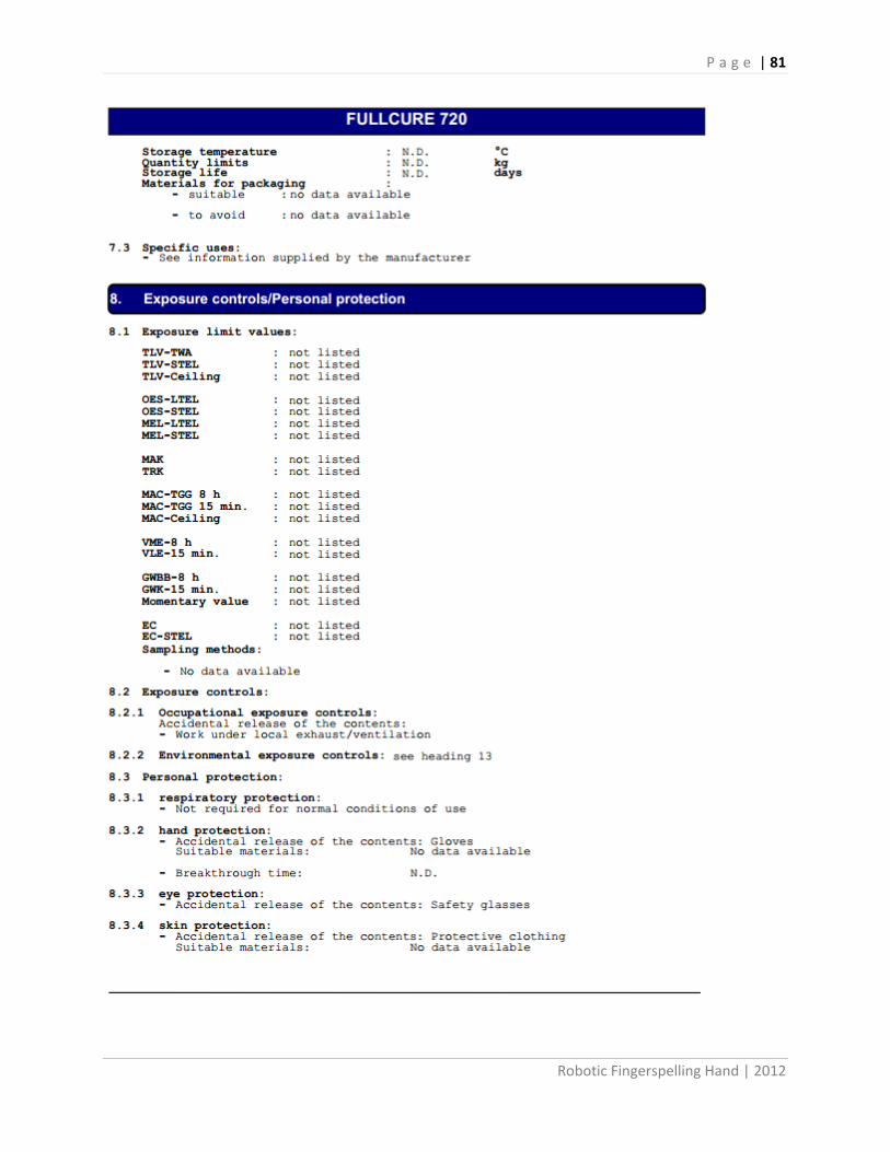
P a g e | 81
Robotic Fingerspelling Hand | 2012

P a g e | 82
Robotic Fingerspelling Hand | 2012

P a g e | 83
Robotic Fingerspelling Hand | 2012

P a g e | 84
Robotic Fingerspelling Hand | 2012

P a g e | 85
Robotic Fingerspelling Hand | 2012

P a g e | 86
Robotic Fingerspelling Hand | 2012

P a g e | 87
Robotic Fingerspelling Hand | 2012
Electricity Costs
Published by the Public Utilities Commission of California
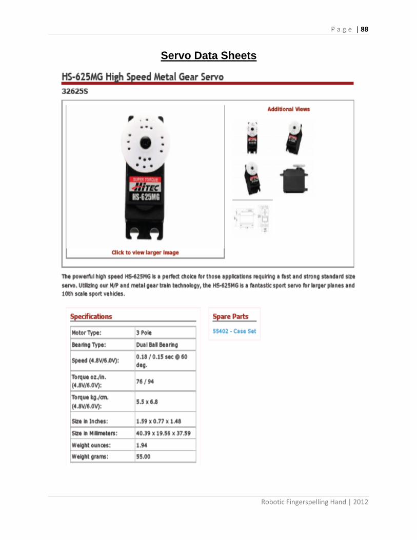
P a g e | 88
Robotic Fingerspelling Hand | 2012
Servo Data Sheets

P a g e | 89
Robotic Fingerspelling Hand | 2012

P a g e | 90
Robotic Fingerspelling Hand | 2012
SERVO Shield Schematic

P a g e | 91
Robotic Fingerspelling Hand | 2012
SERVO Shield PCB Design
Top of Board
Bottom of Board

P a g e | 92
Robotic Fingerspelling Hand | 2012
SERVO Shield BOM

P a g e | 93
Robotic Fingerspelling Hand | 2012

P a g e | 94
Robotic Fingerspelling Hand | 2012

P a g e | 95
Robotic Fingerspelling Hand | 2012

P a g e | 96
Robotic Fingerspelling Hand | 2012
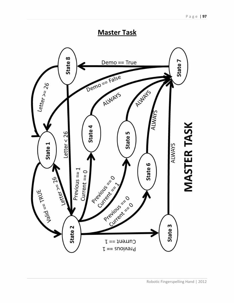
P a g e | 97
Robotic Fingerspelling Hand | 2012
Master Task

P a g e | 98
Robotic Fingerspelling Hand | 2012
Master_task.h //************************************************************************************* /** \file master_task.h * This file contains a task class for the master controller of the project. * * Revisions: * \li 02-06-2012 Created * \li 03-26-2012 Header file accepted by Arduino * \li 04-17-2012 Constructor with pointers accepted in Arduino * License: * This file released under the Lesser GNU Public License, version 2. This program * is intended for educational use only, but it is not limited thereto. */ //************************************************************************************* /// This define prevents this .h file from being included more than once in a .cc file #ifndef _MASTER_TASK_H_ #define _MASTER_TASK_H_ #include <stdlib.h> #include <stdint.h> #include <Servo.h> #include <user_task.h> #if defined(ARDUINO) && ARDUINO >= 100 #include "Arduino.h" #else #include "WProgram.h" #include <pins_arduino.h> #endif class master_task { protected: bool write; // True if motor should be running now bool demo; bool demo_begin; uint8_t state; uint8_t letter; uint8_t thumbdown; uint16_t wordtime; // amount of time to delay between words uint16_t lettertime; // amount of time to delay between uint8_t previousthumb; uint8_t currentthumb; Servo servo1; Servo servo2; Servo servo3; Servo servo4; Servo servo5; Servo servo6; Servo servo7; Servo servo8; Servo servo9; Servo servo10; Servo servo11; user_task *user; public: // The constructor creates a new task object

P a g e | 99
Robotic Fingerspelling Hand | 2012
master_task (user_task*, Servo, Servo)/*, Servo, Servo, Servo, Servo, Servo, Servo, Servo, Servo, Servo); //(task_timer&, time_stamp&)*/; // Tells master that the button was pressed and to run the demo loop void run_demo(void); // Delay between words void wait(uint16_t); // Detaches servos void detach_servos(void); // writes the 0 position to the finger servos void neutral_fingers(void); // writes the zero position to the thumb servos void neutral_thumb(void); // reattaches servos void attach_servos(void); // The run method is where the task actually performs its function void run (void); }; #endif // _MASTER_TASK_H_

P a g e | 100
Robotic Fingerspelling Hand | 2012
Master_task.cpp //************************************************************************************* /** \file master_task.cpp * This file tells the hand what needs to be actuated and when. It also controls the * delay between letters, words, and each time the demo is run. * * Revisions: * \li 02-06-2012 Created * \li 03-26-2012 Header file accepted by Arduino * \li 04-17-2012 Constructor with pointers accepted in Arduino * \li 05-25-2012 fixed demo function/ letter by letter/ sentence input * * License: * This program is intended for fingerspelling use with The Smith-Kettlewell Eye * Research Institute robotic hand, but it is not limited thereto. */ //************************************************************************************* #include <stdlib.h> #include <stdint.h> #include <Arduino.h> #include <user_task.h> #include <Servo.h> #include <master_task.h> #define KNUCKLETHUMB0 140 #define KNUCKLETHUMB30 115 #define KNUCKLETHUMB45 100 #define KNUCKLETHUMB60 80 #define KNUCKLETHUMB90 50 #define MEDIALTHUMB180 140 #define MEDIALTHUMB90 110 #define MEDIALTHUMB80 100 #define MEDIALTHUMB60 95 #define MEDIALTHUMB45 90 #define MEDIALTHUMB30 85 #define MEDIALTHUMB0 80 #define KNUCKLEINDEX0 155 #define KNUCKLEINDEX15 130 #define KNUCKLEINDEX30 125 #define KNUCKLEINDEX45 115 #define KNUCKLEINDEX60 105 #define KNUCKLEINDEX90 95 #define MEDIALINDEX0 110 #define MEDIALINDEX45 85 #define MEDIALINDEX90 65 #define KNUCKLEMIDDLE0 130 #define KNUCKLEMIDDLE30 110 #define KNUCKLEMIDDLE45 105 #define KNUCKLEMIDDLE60 95 #define KNUCKLEMIDDLE90 85 #define MEDIALMIDDLE0 90 #define MEDIALMIDDLE45 65 #define MEDIALMIDDLE90 45 #define KNUCKLERING0 110 #define KNUCKLERING30 80 #define KNUCKLERING45 70 #define KNUCKLERING60 65 #define KNUCKLERING90 55

P a g e | 101
Robotic Fingerspelling Hand | 2012
#define MEDIALRING0 135 #define MEDIALRING45 105 #define MEDIALRING90 80 #define KNUCKLEPINKY0 105 #define KNUCKLEPINKY30 90 #define KNUCKLEPINKY45 75 #define KNUCKLEPINKY60 70 #define KNUCKLEPINKY90 60 #define MEDIALPINKY0 140 #define MEDIALPINKY45 100 #define MEDIALPINKY90 80 #define THUMBIN 1 #define THUMBOUT 0 #define WRISTSTILL 20 #define WRISTTURN 150 uint8_t values [26][13]= { {'A',KNUCKLETHUMB0 ,MEDIALTHUMB90 ,KNUCKLEINDEX90 ,MEDIALINDEX90 ,KNUCKLEMIDDLE90 ,MEDIALMIDDLE90 ,KNUCKLERING90 ,MEDIALRING90 ,KNUCKLEPINKY90 ,MEDIALPINKY90 ,WRISTSTILL ,THUMBOUT}, {'B',KNUCKLETHUMB0 ,MEDIALTHUMB0 ,KNUCKLEINDEX0 ,MEDIALINDEX0 ,KNUCKLEMIDDLE0 ,MEDIALMIDDLE0 ,KNUCKLERING0 ,MEDIALRING0 ,KNUCKLEPINKY0 ,MEDIALPINKY0 ,WRISTSTILL ,THUMBOUT}, {'C',KNUCKLETHUMB60,MEDIALTHUMB45 ,KNUCKLEINDEX45 ,MEDIALINDEX90 ,KNUCKLEMIDDLE30 ,MEDIALMIDDLE90 ,KNUCKLERING45 ,MEDIALRING90 ,KNUCKLEPINKY45 ,MEDIALPINKY90 ,WRISTSTILL ,THUMBOUT}, {'D',KNUCKLETHUMB30,MEDIALTHUMB45 ,KNUCKLEINDEX0 ,MEDIALINDEX0 ,KNUCKLEMIDDLE45 ,MEDIALMIDDLE90 ,KNUCKLERING45 ,MEDIALRING90 ,KNUCKLEPINKY45 ,MEDIALPINKY90 ,WRISTSTILL ,THUMBOUT}, {'E',KNUCKLETHUMB0 ,MEDIALTHUMB0 ,KNUCKLEINDEX0 ,MEDIALINDEX90 ,KNUCKLEMIDDLE0 ,MEDIALINDEX90 ,KNUCKLERING0 ,MEDIALRING90 ,KNUCKLEPINKY0 ,MEDIALPINKY90 ,WRISTSTILL ,THUMBIN }, {'F',KNUCKLETHUMB30,MEDIALTHUMB80 ,KNUCKLEINDEX30 ,MEDIALINDEX90 ,KNUCKLEMIDDLE0 ,MEDIALMIDDLE0 ,KNUCKLERING0 ,MEDIALRING0 ,KNUCKLEPINKY0 ,MEDIALPINKY0 ,WRISTSTILL ,THUMBIN }, {'G',KNUCKLETHUMB0 ,MEDIALTHUMB90 ,KNUCKLEINDEX0 ,MEDIALINDEX0 ,KNUCKLEMIDDLE90 ,MEDIALMIDDLE90 ,KNUCKLERING90 ,MEDIALRING90 ,KNUCKLEPINKY90 ,MEDIALPINKY90 ,WRISTTURN ,THUMBOUT}, {'H',KNUCKLETHUMB0 ,MEDIALTHUMB90 ,KNUCKLEINDEX0 ,MEDIALINDEX0 ,KNUCKLEMIDDLE0 ,MEDIALMIDDLE0 ,KNUCKLERING90 ,MEDIALRING90 ,KNUCKLEPINKY90 ,MEDIALPINKY90 ,WRISTTURN ,THUMBOUT}, {'I',KNUCKLETHUMB0 ,MEDIALTHUMB90 ,KNUCKLEINDEX90 ,MEDIALINDEX90 ,KNUCKLEMIDDLE90 ,MEDIALMIDDLE45 ,KNUCKLERING90 ,MEDIALRING45 ,KNUCKLEPINKY0 ,MEDIALPINKY0 ,WRISTTURN ,THUMBOUT}, {'J',KNUCKLETHUMB0 ,MEDIALTHUMB90 ,KNUCKLEINDEX90 ,MEDIALINDEX90 ,KNUCKLEMIDDLE90 ,MEDIALMIDDLE45 ,KNUCKLERING90 ,MEDIALRING45 ,KNUCKLEPINKY0 ,MEDIALPINKY0 ,WRISTSTILL ,THUMBOUT}, {'K',KNUCKLETHUMB0 ,MEDIALTHUMB80 ,KNUCKLEINDEX0 ,MEDIALINDEX0 ,KNUCKLEMIDDLE45 ,MEDIALMIDDLE0 ,KNUCKLERING90 ,MEDIALRING90 ,KNUCKLEPINKY90 ,MEDIALPINKY90 ,WRISTSTILL ,THUMBOUT}, {'L',KNUCKLETHUMB0 ,MEDIALTHUMB180,KNUCKLEINDEX0 ,MEDIALINDEX0 ,KNUCKLEMIDDLE90 ,MEDIALMIDDLE90 ,KNUCKLERING90 ,MEDIALRING90 ,KNUCKLEPINKY90 ,MEDIALPINKY90 ,WRISTSTILL ,THUMBOUT}, {'M',KNUCKLETHUMB0 ,MEDIALTHUMB30 ,KNUCKLEINDEX60 ,MEDIALINDEX45 ,KNUCKLEMIDDLE60 ,MEDIALMIDDLE45 ,KNUCKLERING45 ,MEDIALRING90 ,KNUCKLEPINKY90 ,MEDIALPINKY90 ,WRISTSTILL ,THUMBIN },

P a g e | 102
Robotic Fingerspelling Hand | 2012
{'N',KNUCKLETHUMB0 ,MEDIALTHUMB30 ,KNUCKLEINDEX60 ,MEDIALINDEX45 ,KNUCKLEMIDDLE60 ,MEDIALMIDDLE45 ,KNUCKLERING90 ,MEDIALRING90 ,KNUCKLEPINKY90 ,MEDIALPINKY90 ,WRISTSTILL ,THUMBIN }, {'O',KNUCKLETHUMB30,MEDIALTHUMB45 ,KNUCKLEINDEX45 ,MEDIALINDEX90 ,KNUCKLEMIDDLE45 ,MEDIALMIDDLE90 ,KNUCKLERING45 ,MEDIALRING90 ,KNUCKLEPINKY45 ,MEDIALPINKY90 ,WRISTSTILL ,THUMBIN }, {'P',KNUCKLETHUMB0 ,MEDIALTHUMB90 ,KNUCKLEINDEX0 ,MEDIALINDEX0 ,KNUCKLEMIDDLE60 ,MEDIALMIDDLE45 ,KNUCKLERING90 ,MEDIALRING90 ,KNUCKLEPINKY90 ,MEDIALPINKY90 ,WRISTSTILL ,THUMBOUT}, {'Q',KNUCKLETHUMB45,MEDIALTHUMB90 ,KNUCKLEINDEX90 ,MEDIALINDEX0 ,KNUCKLEMIDDLE90 ,MEDIALMIDDLE90 ,KNUCKLERING90 ,MEDIALRING90 ,KNUCKLEPINKY90 ,MEDIALPINKY90 ,WRISTSTILL ,THUMBOUT}, {'R',KNUCKLETHUMB30,MEDIALTHUMB45 ,KNUCKLEINDEX15 ,MEDIALINDEX0 ,KNUCKLEMIDDLE0 ,MEDIALMIDDLE0 ,KNUCKLERING30 ,MEDIALRING90 ,KNUCKLEPINKY90 ,MEDIALPINKY90 ,WRISTSTILL ,THUMBOUT}, {'S',KNUCKLETHUMB30,MEDIALTHUMB60 ,KNUCKLEINDEX90 ,MEDIALINDEX90 ,KNUCKLEMIDDLE90 ,MEDIALMIDDLE90 ,KNUCKLERING90 ,MEDIALRING90 ,KNUCKLEPINKY90 ,MEDIALPINKY90 ,WRISTSTILL ,THUMBOUT}, {'T',KNUCKLETHUMB0 ,MEDIALTHUMB45 ,KNUCKLEINDEX45 ,MEDIALINDEX90 ,KNUCKLEMIDDLE90 ,MEDIALMIDDLE90 ,KNUCKLERING90 ,MEDIALRING90 ,KNUCKLEPINKY90 ,MEDIALPINKY90 ,WRISTSTILL ,THUMBIN }, {'U',KNUCKLETHUMB30,MEDIALTHUMB30 ,KNUCKLEINDEX0 ,MEDIALINDEX0 ,KNUCKLEMIDDLE0 ,MEDIALMIDDLE0 ,KNUCKLERING30 ,MEDIALRING90 ,KNUCKLEPINKY90 ,MEDIALPINKY90 ,WRISTSTILL ,THUMBOUT}, {'V',KNUCKLETHUMB30,MEDIALTHUMB80 ,KNUCKLEINDEX0 ,MEDIALINDEX0 ,KNUCKLEMIDDLE90 ,MEDIALMIDDLE90 ,KNUCKLERING0 ,MEDIALRING0 ,KNUCKLEPINKY90 ,MEDIALPINKY90 ,WRISTSTILL ,THUMBOUT}, {'W',KNUCKLETHUMB30,MEDIALTHUMB30 ,KNUCKLEINDEX0 ,MEDIALINDEX0 ,KNUCKLEMIDDLE0 ,MEDIALMIDDLE0 ,KNUCKLERING0 ,MEDIALRING0 ,KNUCKLEPINKY90 ,MEDIALPINKY90 ,WRISTSTILL ,THUMBOUT}, {'X',KNUCKLETHUMB30,MEDIALTHUMB30 ,KNUCKLEINDEX0 ,MEDIALINDEX90 ,KNUCKLEMIDDLE90 ,MEDIALMIDDLE90 ,KNUCKLERING90 ,MEDIALRING90 ,KNUCKLEPINKY90 ,MEDIALPINKY90 ,WRISTSTILL ,THUMBOUT}, {'Y',KNUCKLETHUMB0 ,MEDIALTHUMB180,KNUCKLEINDEX90 ,MEDIALINDEX90 ,KNUCKLEMIDDLE90 ,MEDIALMIDDLE90 ,KNUCKLERING90 ,MEDIALRING90 ,KNUCKLEPINKY0 ,MEDIALPINKY0 ,WRISTSTILL ,THUMBOUT}, {'Z',KNUCKLETHUMB45,MEDIALTHUMB45 ,KNUCKLEINDEX0 ,MEDIALINDEX0 ,KNUCKLEMIDDLE90 ,MEDIALMIDDLE90 ,KNUCKLERING90 ,MEDIALRING90 ,KNUCKLEPINKY90 ,MEDIALPINKY90 ,WRISTTURN ,THUMBOUT} }; master_task::master_task (user_task *usertask, Servo servoone, Servo servotwo)/*, servo servo3, servo servo4, servo servo5, servo servo6, servo servo7, servo servo8, servo servo9, servo servo10,servo servo11)*/ { servo1 = servoone; servo2 = servotwo; user = usertask; letter = 0; write = false; wordtime = 1000; lettertime = 500; previousthumb = 0; currentthumb = 0; state=0; } void master_task::run_demo(void) { demo = true; demo_begin = true;

P a g e | 103
Robotic Fingerspelling Hand | 2012
state = 8; } void master_task::wait(uint16_t delaytime) { for(volatile int i = 0; i<=delaytime; i++) { } } void master_task::detach_servos(void) { servo1.detach(); servo2.detach(); servo3.detach(); servo4.detach(); servo5.detach(); servo6.detach(); servo7.detach(); servo8.detach(); servo9.detach(); servo10.detach(); servo11.detach(); } void master_task::neutral_fingers(void) { servo3.write(KNUCKLEINDEX0); servo4.write(MEDIALINDEX0); servo5.write(KNUCKLEMIDDLE0); servo6.write(MEDIALMIDDLE0); servo7.write(KNUCKLERING0); servo8.write(MEDIALRING0); servo9.write(KNUCKLEPINKY0); servo10.write(MEDIALPINKY0); } void master_task::neutral_thumb(void) { servo1.write(KNUCKLETHUMB0); servo2.write(MEDIALTHUMB180); } void master_task::attach_servos(void) { servo1.attach(11); // KNUCKLETHUMB servo2.attach(2); // MEDIALTHUMB servo3.attach(3); // KNUCKLEINDEX servo4.attach(4); // MEDIALINDEX servo5.attach(5); // KNUCKLEMIDDLE servo6.attach(6); // MEDIALMIDDLE servo7.attach(7); // KNUCKLERING servo8.attach(8); // MEDIALRING servo9.attach(9); // KNUCKLEPINKY servo10.attach(10); // MEDIALPINKY servo11.attach(12); // Wrist neutral_fingers(); neutral_thumb(); } void master_task::run (void) { switch(state)

P a g e | 104
Robotic Fingerspelling Hand | 2012
{ case(0): attach_servos(); state = 1; break; case(1): write = user->got_letter(); if(write==true) { letter = user->input_letter(); user->reset(); state=2; } break; case(2): currentthumb = values[letter][12]; if(letter == 26) { if(lettertime >= 200) { lettertime -= 100; Serial.println(lettertime); } user->get_next_letter(); state = 1; } else if(letter == 27) { if(lettertime <= 2000) { lettertime += 100; Serial.println(lettertime); } user->get_next_letter(); state = 1; } else if (letter == 28) { neutral_finger(); neutral_thumb(); delay(wordtime); user->get_next_letter(); state = 1; } else if (letter == 29) { detach_servos(); user->get_next_letter(); state = 1; } else if (letter == 30) { attach_servos(); user->get_next_letter(); state = 1; } else if (previousthumb == 1 && currentthumb == 1) {

P a g e | 105
Robotic Fingerspelling Hand | 2012
state = 3; } else if (previousthumb == 0 && currentthumb == 1) { state = 4; } else if(previousthumb == 1 && currentthumb == 0) { state = 5; } else { state = 6; } previousthumb = currentthumb; break; case(3): Serial.println("thumb inside to another letter with thumb inside"); Serial.println("Fingers move to zero"); Serial.println("thumb Move to position"); Serial.println("fingers move to position"); neutral_fingers(); delay(100); servo1.write(values[letter][1]); servo2.write(values[letter][2]); servo3.write(values[letter][3]); servo4.write(values[letter][4]); servo5.write(values[letter][5]); servo6.write(values[letter][6]); servo7.write(values[letter][7]); servo8.write(values[letter][8]); servo9.write(values[letter][9]); servo10.write(values[letter][10]); servo11.write(values[letter][11]); state = 7; break; case(4): Serial.println("thumb outside to letter with thumb inside"); Serial.println("thumb move to zero"); Serial.println("fingers move to zero"); Serial.println(" thumb Move to position"); Serial.println(" fingers move to position"); neutral_thumb(); delay(100); neutral_fingers(); delay(100); servo1.write(values[letter][1]); servo2.write(values[letter][2]); delay(150); servo3.write(values[letter][3]); servo4.write(values[letter][4]); servo5.write(values[letter][5]); servo6.write(values[letter][6]); servo7.write(values[letter][7]); servo8.write(values[letter][8]); servo9.write(values[letter][9]);

P a g e | 106
Robotic Fingerspelling Hand | 2012
servo10.write(values[letter][10]); servo11.write(values[letter][11]); state = 7; break; case(5): Serial.println("thumb inside to letter with thumb outside"); Serial.println("fingers move to zero"); Serial.println("thumb move to zero"); Serial.println(" fingers move to position"); Serial.println(" thumb Move to position"); neutral_fingers(); delay(100); neutral_thumb(); delay(100); servo3.write(values[letter][3]); servo4.write(values[letter][4]); servo5.write(values[letter][5]); servo6.write(values[letter][6]); servo7.write(values[letter][7]); servo8.write(values[letter][8]); servo9.write(values[letter][9]); servo10.write(values[letter][10]); servo1.write(values[letter][1]); servo2.write(values[letter][2]); servo11.write(values[letter][11]); state = 7; break; case(6): Serial.println("thumb outside to letter with thumb outside"); Serial.println("thumb move to zero"); Serial.println(" fingers move to position"); Serial.println(" thumb Move to position"); neutral_thumb(); delay(100); servo3.write(values[letter][3]); servo4.write(values[letter][4]); servo5.write(values[letter][5]); servo6.write(values[letter][6]); servo7.write(values[letter][7]); servo8.write(values[letter][8]); servo9.write(values[letter][9]); servo10.write(values[letter][10]); servo1.write(values[letter][1]); servo2.write(values[letter][2]); servo11.write(values[letter][11]); state = 7; break; case(7): Serial.println((char)values[letter][0]); delay(lettertime); user->get_next_letter(); if(demo) { state = 8; }

P a g e | 107
Robotic Fingerspelling Hand | 2012
else { state = 1; } break; case(8): letter ++; if(demo_begin) { demo_begin = false; letter = 0; state = 2; } else if(letter == 26) { demo = false; delay(10000); state = 1; } else { state = 2; } break; default: Serial.println('Error State'); break; } }

P a g e | 108
Robotic Fingerspelling Hand | 2012
Servo Code Servo.h Servo.h - Interrupt driven Servo library for Arduino using 16 bit timers- Version 2 Copyright (c) 2009 Michael Margolis. All right reserved. This library is free software; you can redistribute it and/or modify it under the terms of the GNU Lesser General Public License as published by the Free Software Foundation; either version 2.1 of the License, or (at your option) any later version. This library is distributed in the hope that it will be useful, but WITHOUT ANY WARRANTY; without even the implied warranty of MERCHANTABILITY or FITNESS FOR A PARTICULAR PURPOSE. See the GNU Lesser General Public License for more details. You should have received a copy of the GNU Lesser General Public License along with this library; if not, write to the Free Software Foundation, Inc., 51 Franklin St, Fifth Floor, Boston, MA 02110-1301 USA */ /* A servo is activated by creating an instance of the Servo class passing the desired pin to the attach() method. The servos are pulsed in the background using the value most recently written using the write() method Note that analogWrite of PWM on pins associated with the timer are disabled when the first servo is attached. Timers are seized as needed in groups of 12 servos - 24 servos use two timers, 48 servos will use four. The sequence used to sieze timers is defined in timers.h The methods are: Servo - Class for manipulating servo motors connected to Arduino pins. attach(pin ) - Attaches a servo motor to an i/o pin. attach(pin, min, max ) - Attaches to a pin setting min and max values in microseconds default min is 544, max is 2400 write() - Sets the servo angle in degrees. (invalid angle that is valid as pulse in microseconds is treated as microseconds) writeMicroseconds() - Sets the servo pulse width in microseconds read() - Gets the last written servo pulse width as an angle between 0 and 180. readMicroseconds() - Gets the last written servo pulse width in microseconds. (was read_us() in first release) attached() - Returns true if there is a servo attached. detach() - Stops an attached servos from pulsing its i/o pin. */ #ifndef Servo_h #define Servo_h #include <inttypes.h> /* * Defines for 16 bit timers used with Servo library * * If _useTimerX is defined then TimerX is a 16 bit timer on the curent board * timer16_Sequence_t enumerates the sequence that the timers should be allocated * _Nbr_16timers indicates how many 16 bit timers are available.

P a g e | 109
Robotic Fingerspelling Hand | 2012
* */ // Say which 16 bit timers can be used and in what order #if defined(__AVR_ATmega1280__) || defined(__AVR_ATmega2560__) #define _useTimer5 #define _useTimer1 #define _useTimer3 #define _useTimer4 typedef enum { _timer5, _timer1, _timer3, _timer4, _Nbr_16timers } timer16_Sequence_t ; #elif defined(__AVR_ATmega32U4__) #define _useTimer3 #define _useTimer1 typedef enum { _timer3, _timer1, _Nbr_16timers } timer16_Sequence_t ; #elif defined(__AVR_AT90USB646__) || defined(__AVR_AT90USB1286__) #define _useTimer3 #define _useTimer1 typedef enum { _timer3, _timer1, _Nbr_16timers } timer16_Sequence_t ; #elif defined(__AVR_ATmega128__) ||defined(__AVR_ATmega1281__)||defined(__AVR_ATmega2561__) #define _useTimer3 #define _useTimer1 typedef enum { _timer3, _timer1, _Nbr_16timers } timer16_Sequence_t ; #else // everything else #define _useTimer1 typedef enum { _timer1, _Nbr_16timers } timer16_Sequence_t ; #endif #define Servo_VERSION 2 // software version of this library #define MIN_PULSE_WIDTH 544 // the shortest pulse sent to a servo #define MAX_PULSE_WIDTH 2400 // the longest pulse sent to a servo #define DEFAULT_PULSE_WIDTH 1500 // default pulse width when servo is attached #define REFRESH_INTERVAL 20000 // minumim time to refresh servos in microseconds #define SERVOS_PER_TIMER 12 // the maximum number of servos controlled by one timer #define MAX_SERVOS (_Nbr_16timers * SERVOS_PER_TIMER) #define INVALID_SERVO 255 // flag indicating an invalid servo index typedef struct { uint8_t nbr :6 ; // a pin number from 0 to 63 uint8_t isActive :1 ; // true if this channel is enabled, pin not pulsed if false } ServoPin_t ; typedef struct { ServoPin_t Pin; unsigned int ticks; } servo_t; class Servo { public: Servo();

P a g e | 110
Robotic Fingerspelling Hand | 2012
uint8_t attach(int pin); // attach the given pin to the next free channel, sets pinMode, returns channel number or 0 if failure uint8_t attach(int pin, int min, int max); // as above but also sets min and max values for writes. void detach(); void write(int value); // if value is < 200 its treated as an angle, otherwise as pulse width in microseconds void writeMicroseconds(int value); // Write pulse width in microseconds int read(); // returns current pulse width as an angle between 0 and 180 degrees int readMicroseconds(); // returns current pulse width in microseconds for this servo (was read_us() in first release) bool attached(); // return true if this servo is attached, otherwise false private: uint8_t servoIndex; // index into the channel data for this servo int8_t min; // minimum is this value times 4 added to MIN_PULSE_WIDTH int8_t max; // maximum is this value times 4 added to MAX_PULSE_WIDTH }; #endif

P a g e | 111
Robotic Fingerspelling Hand | 2012
Servo.cpp Servo.cpp - Interrupt driven Servo library for Arduino using 16 bit timers- Version 2 Copyright (c) 2009 Michael Margolis. All right reserved. This library is free software; you can redistribute it and/or modify it under the terms of the GNU Lesser General Public License as published by the Free Software Foundation; either version 2.1 of the License, or (at your option) any later version. This library is distributed in the hope that it will be useful, but WITHOUT ANY WARRANTY; without even the implied warranty of MERCHANTABILITY or FITNESS FOR A PARTICULAR PURPOSE. See the GNU Lesser General Public License for more details. You should have received a copy of the GNU Lesser General Public License along with this library; if not, write to the Free Software Foundation, Inc., 51 Franklin St, Fifth Floor, Boston, MA 02110-1301 USA */ /* A servo is activated by creating an instance of the Servo class passing the desired pin to the attach() method. The servos are pulsed in the background using the value most recently written using the write() method Note that analogWrite of PWM on pins associated with the timer are disabled when the first servo is attached. Timers are seized as needed in groups of 12 servos - 24 servos use two timers, 48 servos will use four. The methods are: Servo - Class for manipulating servo motors connected to Arduino pins. attach(pin ) - Attaches a servo motor to an i/o pin. attach(pin, min, max ) - Attaches to a pin setting min and max values in microseconds default min is 544, max is 2400 write() - Sets the servo angle in degrees. (invalid angle that is valid as pulse in microseconds is treated as microseconds) writeMicroseconds() - Sets the servo pulse width in microseconds read() - Gets the last written servo pulse width as an angle between 0 and 180. readMicroseconds() - Gets the last written servo pulse width in microseconds. (was read_us() in first release) attached() - Returns true if there is a servo attached. detach() - Stops an attached servos from pulsing its i/o pin. */ #include <avr/interrupt.h> #include <WProgram.h> #include "Servo.h" #define usToTicks(_us) (( clockCyclesPerMicrosecond()* _us) / 8) // converts microseconds to tick (assumes prescale of 8) // 12 Aug 2009 #define ticksToUs(_ticks) (( (unsigned)_ticks * 8)/ clockCyclesPerMicrosecond() ) // converts from ticks back to microseconds #define TRIM_DURATION 2 // compensation ticks to trim adjust for digitalWrite delays // 12 August 2009 //#define NBR_TIMERS (MAX_SERVOS / SERVOS_PER_TIMER)

P a g e | 112
Robotic Fingerspelling Hand | 2012
static servo_t servos[MAX_SERVOS]; // static array of servo structures static volatile int8_t Channel[_Nbr_16timers ]; // counter for the servo being pulsed for each timer (or -1 if refresh interval) uint8_t ServoCount = 0; // the total number of attached servos // convenience macros #define SERVO_INDEX_TO_TIMER(_servo_nbr) ((timer16_Sequence_t)(_servo_nbr / SERVOS_PER_TIMER)) // returns the timer controlling this servo #define SERVO_INDEX_TO_CHANNEL(_servo_nbr) (_servo_nbr % SERVOS_PER_TIMER) // returns the index of the servo on this timer #define SERVO_INDEX(_timer,_channel) ((_timer*SERVOS_PER_TIMER) + _channel) // macro to access servo index by timer and channel #define SERVO(_timer,_channel) (servos[SERVO_INDEX(_timer,_channel)]) // macro to access servo class by timer and channel #define SERVO_MIN() (MIN_PULSE_WIDTH - this->min * 4) // minimum value in uS for this servo #define SERVO_MAX() (MAX_PULSE_WIDTH - this->max * 4) // maximum value in uS for this servo /************ static functions common to all instances ***********************/ static inline void handle_interrupts(timer16_Sequence_t timer, volatile uint16_t *TCNTn, volatile uint16_t* OCRnA) { if( Channel[timer] < 0 ) *TCNTn = 0; // channel set to -1 indicated that refresh interval completed so reset the timer else{ if( SERVO_INDEX(timer,Channel[timer]) < ServoCount && SERVO(timer,Channel[timer]).Pin.isActive == true ) digitalWrite( SERVO(timer,Channel[timer]).Pin.nbr,LOW); // pulse this channel low if activated } Channel[timer]++; // increment to the next channel if( SERVO_INDEX(timer,Channel[timer]) < ServoCount && Channel[timer] < SERVOS_PER_TIMER) { *OCRnA = *TCNTn + SERVO(timer,Channel[timer]).ticks; if(SERVO(timer,Channel[timer]).Pin.isActive == true) // check if activated digitalWrite( SERVO(timer,Channel[timer]).Pin.nbr,HIGH); // its an active channel so pulse it high } else { // finished all channels so wait for the refresh period to expire before starting over if( (unsigned)*TCNTn < (usToTicks(REFRESH_INTERVAL) + 4) ) // allow a few ticks to ensure the next OCR1A not missed *OCRnA = (unsigned int)usToTicks(REFRESH_INTERVAL); else *OCRnA = *TCNTn + 4; // at least REFRESH_INTERVAL has elapsed Channel[timer] = -1; // this will get incremented at the end of the refresh period to start again at the first channel } } #ifndef WIRING // Wiring pre-defines signal handlers so don't define any if compiling for the Wiring platform // Interrupt handlers for Arduino #if defined(_useTimer1) SIGNAL (TIMER1_COMPA_vect) { handle_interrupts(_timer1, &TCNT1, &OCR1A); } #endif #if defined(_useTimer3) SIGNAL (TIMER3_COMPA_vect)

P a g e | 113
Robotic Fingerspelling Hand | 2012
{ handle_interrupts(_timer3, &TCNT3, &OCR3A); } #endif #if defined(_useTimer4) SIGNAL (TIMER4_COMPA_vect) { handle_interrupts(_timer4, &TCNT4, &OCR4A); } #endif #if defined(_useTimer5) SIGNAL (TIMER5_COMPA_vect) { handle_interrupts(_timer5, &TCNT5, &OCR5A); } #endif #elif defined WIRING // Interrupt handlers for Wiring #if defined(_useTimer1) void Timer1Service() { handle_interrupts(_timer1, &TCNT1, &OCR1A); } #endif #if defined(_useTimer3) void Timer3Service() { handle_interrupts(_timer3, &TCNT3, &OCR3A); } #endif #endif static void initISR(timer16_Sequence_t timer) { #if defined (_useTimer1) if(timer == _timer1) { TCCR1A = 0; // normal counting mode TCCR1B = _BV(CS11); // set prescaler of 8 TCNT1 = 0; // clear the timer count #if defined(__AVR_ATmega8__)|| defined(__AVR_ATmega128__) TIFR |= _BV(OCF1A); // clear any pending interrupts; TIMSK |= _BV(OCIE1A) ; // enable the output compare interrupt #else // here if not ATmega8 or ATmega128 TIFR1 |= _BV(OCF1A); // clear any pending interrupts; TIMSK1 |= _BV(OCIE1A) ; // enable the output compare interrupt #endif #if defined(WIRING) timerAttach(TIMER1OUTCOMPAREA_INT, Timer1Service); #endif } #endif #if defined (_useTimer3)

P a g e | 114
Robotic Fingerspelling Hand | 2012
if(timer == _timer3) { TCCR3A = 0; // normal counting mode TCCR3B = _BV(CS31); // set prescaler of 8 TCNT3 = 0; // clear the timer count #if defined(__AVR_ATmega128__) TIFR |= _BV(OCF3A); // clear any pending interrupts; ETIMSK |= _BV(OCIE3A); // enable the output compare interrupt #else TIFR3 = _BV(OCF3A); // clear any pending interrupts; TIMSK3 = _BV(OCIE3A) ; // enable the output compare interrupt #endif #if defined(WIRING) timerAttach(TIMER3OUTCOMPAREA_INT, Timer3Service); // for Wiring platform only #endif } #endif #if defined (_useTimer4) if(timer == _timer4) { TCCR4A = 0; // normal counting mode TCCR4B = _BV(CS41); // set prescaler of 8 TCNT4 = 0; // clear the timer count TIFR4 = _BV(OCF4A); // clear any pending interrupts; TIMSK4 = _BV(OCIE4A) ; // enable the output compare interrupt } #endif #if defined (_useTimer5) if(timer == _timer5) { TCCR5A = 0; // normal counting mode TCCR5B = _BV(CS51); // set prescaler of 8 TCNT5 = 0; // clear the timer count TIFR5 = _BV(OCF5A); // clear any pending interrupts; TIMSK5 = _BV(OCIE5A) ; // enable the output compare interrupt } #endif } static void finISR(timer16_Sequence_t timer) { //disable use of the given timer #if defined WIRING // Wiring if(timer == _timer1) { #if defined(__AVR_ATmega1281__)||defined(__AVR_ATmega2561__) TIMSK1 &= ~_BV(OCIE1A) ; // disable timer 1 output compare interrupt #else TIMSK &= ~_BV(OCIE1A) ; // disable timer 1 output compare interrupt #endif timerDetach(TIMER1OUTCOMPAREA_INT); } else if(timer == _timer3) { #if defined(__AVR_ATmega1281__)||defined(__AVR_ATmega2561__) TIMSK3 &= ~_BV(OCIE3A); // disable the timer3 output compare A interrupt #else ETIMSK &= ~_BV(OCIE3A); // disable the timer3 output compare A interrupt #endif timerDetach(TIMER3OUTCOMPAREA_INT); }

P a g e | 115
Robotic Fingerspelling Hand | 2012
#else //For Arduino - in future: call here to a currently undefined function to reset the timer #endif } static boolean isTimerActive(timer16_Sequence_t timer) { // returns true if any servo is active on this timer for(uint8_t channel=0; channel < SERVOS_PER_TIMER; channel++) { if(SERVO(timer,channel).Pin.isActive == true) return true; } return false; } /****************** end of static functions ******************************/ Servo::Servo() { if( ServoCount < MAX_SERVOS) { this->servoIndex = ServoCount++; // assign a servo index to this instance servos[this->servoIndex].ticks = usToTicks(DEFAULT_PULSE_WIDTH); // store default values - 12 Aug 2009 } else this->servoIndex = INVALID_SERVO ; // too many servos } uint8_t Servo::attach(int pin) { return this->attach(pin, MIN_PULSE_WIDTH, MAX_PULSE_WIDTH); } uint8_t Servo::attach(int pin, int min, int max) { if(this->servoIndex < MAX_SERVOS ) { pinMode( pin, OUTPUT) ; // set servo pin to output servos[this->servoIndex].Pin.nbr = pin; // todo min/max check: abs(min - MIN_PULSE_WIDTH) /4 < 128 this->min = (MIN_PULSE_WIDTH - min)/4; //resolution of min/max is 4 uS this->max = (MAX_PULSE_WIDTH - max)/4; // initialize the timer if it has not already been initialized timer16_Sequence_t timer = SERVO_INDEX_TO_TIMER(servoIndex); if(isTimerActive(timer) == false) initISR(timer); servos[this->servoIndex].Pin.isActive = true; // this must be set after the check for isTimerActive } return this->servoIndex ; } void Servo::detach() { servos[this->servoIndex].Pin.isActive = false; timer16_Sequence_t timer = SERVO_INDEX_TO_TIMER(servoIndex); if(isTimerActive(timer) == false) { finISR(timer); } }

P a g e | 116
Robotic Fingerspelling Hand | 2012
void Servo::write(int value) { if(value < MIN_PULSE_WIDTH) { // treat values less than 544 as angles in degrees (valid values in microseconds are handled as microseconds) if(value < 0) value = 0; if(value > 180) value = 180; value = map(value, 0, 180, SERVO_MIN(), SERVO_MAX()); } this->writeMicroseconds(value); } void Servo::writeMicroseconds(int value) { // calculate and store the values for the given channel byte channel = this->servoIndex; if( (channel >= 0) && (channel < MAX_SERVOS) ) // ensure channel is valid { if( value < SERVO_MIN() ) // ensure pulse width is valid value = SERVO_MIN(); else if( value > SERVO_MAX() ) value = SERVO_MAX(); value = value - TRIM_DURATION; value = usToTicks(value); // convert to ticks after compensating for interrupt overhead - 12 Aug 2009 uint8_t oldSREG = SREG; cli(); servos[channel].ticks = value; SREG = oldSREG; } } int Servo::read() // return the value as degrees { return map( this->readMicroseconds()+1, SERVO_MIN(), SERVO_MAX(), 0, 180); } int Servo::readMicroseconds() { unsigned int pulsewidth; if( this->servoIndex != INVALID_SERVO ) pulsewidth = ticksToUs(servos[this->servoIndex].ticks) + TRIM_DURATION ; // 12 aug 2009 else pulsewidth = 0; return pulsewidth; } bool Servo::attached() { return servos[this->servoIndex].Pin.isActive ; }
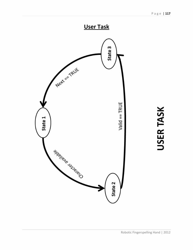
P a g e | 117
Robotic Fingerspelling Hand | 2012
User Task

P a g e | 118
Robotic Fingerspelling Hand | 2012
User_task.h //************************************************************************************* /** \file user_task.h * This file contains a task class for running a user interface for the motor * controller. It has a single-state task which just reads the serial port to see if * the user typed anything * * Revisions: * \li 02-06-2012 Created generic switch cases * \li 03-26-2012 Header file accepted by Arduino * \li 04-17-2012 Constructor with pointers accepted in Arduino * \li 05-02-2012 Added functions to be used with Master_task * * License: * This program is intended for fingerspelling use with The Smith-Kettlewell Eye * Research Institute robotic hand, but it is not limited thereto. */ //************************************************************************************* /// This define prevents this .h file from being included more than once in a .cc file #ifndef _USER_TASK_H_ #define _USER_TASK_H_ #include <stdlib.h> #include <stdint.h> #if defined(ARDUINO) && ARDUINO >= 100 #include "Arduino.h" #else #include "WProgram.h" #include <pins_arduino.h> #endif //------------------------------------------------------------------------------------- /** This class contains a task which... */ class user_task //: public stl_task { // This protected data can only be accessed from this class or its descendents protected: bool valid; bool next; uint8_t letter; uint8_t state; char input_char; public: // The constructor creates a new task object user_task (); // The run method is where the task actually performs its function void run (void); //This function will display an introduction in the serial monitor void intro(void); // This function is a flag to see if a valid letter was received bool got_letter(void); // This function returns the current letter received uint8_t input_letter(void); // This function clears the input variables

P a g e | 119
Robotic Fingerspelling Hand | 2012
void reset(void); // This function tells user when to get the next letter void get_next_letter(void); }; #endif // _TASK_USER_H_

P a g e | 120
Robotic Fingerspelling Hand | 2012
User_task.cpp //************************************************************************************* /** \file user_task.cpp * This file tells the master file what letters (A-Z) are to be formed by accepting * input from the user. It also allows the user to modify the delay between letters. * * Revisions: * \li 02-06-2012 Created generic switch cases * \li 03-26-2012 Header file accepted by Arduino * \li 04-17-2012 Constructor with pointers accepted in Arduino * \li 05-02-2012 Added functions to be used with Master_task * * License: * This program is intended for fingerspelling use with The Smith-Kettlewell Eye * Research Institute robotic hand, but it is not limited thereto. */ //************************************************************************************* #include <stdlib.h> #include <stdint.h> #include "user_task.h" #if defined(ARDUINO) && ARDUINO >= 100 #include "Arduino.h" #else #include "WProgram.h" #include <pins_arduino.h> #endif //------------------------------------------------------------------------------------- /** This constructor creates a user interface task object. It checks if the user has * typed a command at the serial port and if so tells the servos what to do. */ user_task::user_task ()//(task_timer& a_timer, time_stamp& t_stamp) //: stl_task (a_timer, t_stamp) { letter = 0; state = 0; valid = false; next= false; input_char = 0; } //------------------------------------------------------------------------------------- /** This is the function which runs when it is called by the master file. */ void user_task::run (void) { // There's no switch statement because this task only does one thing all the time: // check for a character, and perform a command if(state ==0) { state = 1; intro(); } else if (state == 1) { if (Serial.available() > 0)

P a g e | 121
Robotic Fingerspelling Hand | 2012
{ input_char = Serial.read(); state = 2; } } else if (state ==2) { switch (input_char) { // Pressing the '+' key increases finger-spelling speed case ('+'): case ('='): Serial.print("\nIncreasing speed\n"); valid = true; letter = 26; state = 3; break; // Pressing the '-' key decreases finger-spelling speed case ('_'): case ('-'): Serial.print("\nDecreasing speed\n"); valid = true; letter = 27; state = 3; break; // Pressing the 'space' key provides a space between letters case (' '): Serial.print(" "); valid = true; letter = 28; state = 3; break; // Pressing the '0' key disconnects all servos case ('0'): Serial.print("\nDetach servos\n"); valid = true; letter = 29; state = 3; break; // Pressing the '1' connects all servos for use case ('1'): Serial.print("\nAttach servos\n"); valid = true; letter = 30; state = 3; break; // Pressing the 'A' key forms the corresponding letter of the alphabet case ('A'): case ('a'): Serial.print("A"); valid = true; letter = 0; state = 3; break; // Pressing the 'B' key forms the corresponding letter of the alphabet case ('B'): case ('b'): Serial.print("B");

P a g e | 122
Robotic Fingerspelling Hand | 2012
valid = true; letter = 1; state = 3; break; // Pressing the 'C' key forms the corresponding letter of the alphabet case ('C'): case ('c'): Serial.print("C"); valid = true; letter = 2; state = 3; break; // Pressing the 'D' key forms the corresponding letter of the alphabet case ('D'): case ('d'): Serial.print("D"); valid = true; letter = 3; state = 3; break; // Pressing the 'E' key forms the corresponding letter of the alphabet case ('E'): case ('e'): Serial.print("E"); valid = true; letter = 4; state = 3; break; // Pressing the 'F' key forms the corresponding letter of the alphabet case ('F'): case ('f'): Serial.print("F"); valid = true; letter = 5; state = 3; break; // Pressing the 'G' key forms the corresponding letter of the alphabet case ('G'): case ('g'): Serial.print("G"); valid = true; letter = 6; state = 3; break; // Pressing the 'H' key forms the corresponding letter of the alphabet case ('H'): case ('h'): Serial.print("H"); valid = true; letter = 7; state = 3; break; // Pressing the 'I' key forms the corresponding letter of the alphabet case ('I'): case ('i'): Serial.print("I"); valid = true; letter = 8;

P a g e | 123
Robotic Fingerspelling Hand | 2012
state = 3; break; // Pressing the 'J' key forms the corresponding letter of the alphabet case ('J'): case ('j'): Serial.print("J"); valid = true; letter = 9; state = 3; break; // Pressing the 'K' key forms the corresponding letter of the alphabet case ('K'): case ('k'): Serial.print("K"); valid = true; letter = 10; state = 3; break; // Pressing the 'L' key forms the corresponding letter of the alphabet case ('L'): case ('l'): Serial.print("L"); valid = true; letter = 11; state = 3; break; // Pressing the 'M' key forms the corresponding letter of the alphabet case ('M'): case ('m'): Serial.print("M"); valid = true; letter = 12; state = 3; break; // Pressing the 'N' key forms the corresponding letter of the alphabet case ('N'): case ('n'): Serial.print("N"); valid = true; letter = 13; state = 3; break; // Pressing the 'O' key forms the corresponding letter of the alphabet case ('O'): case ('o'): Serial.print("O"); valid = true; letter = 14; state = 3; break; // Pressing the 'P' key forms the corresponding letter of the alphabet case ('P'): case ('p'): Serial.print("P"); valid = true; letter = 15; state = 3; break;
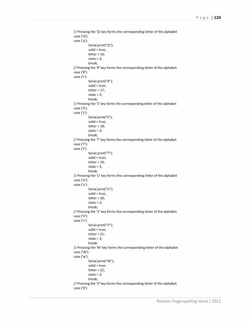
P a g e | 124
Robotic Fingerspelling Hand | 2012
// Pressing the 'Q' key forms the corresponding letter of the alphabet case ('Q'): case ('q'): Serial.print("Q"); valid = true; letter = 16; state = 3; break; // Pressing the 'R' key forms the corresponding letter of the alphabet case ('R'): case ('r'): Serial.print("R"); valid = true; letter = 17; state = 3; break; // Pressing the 'S' key forms the corresponding letter of the alphabet case ('S'): case ('s'): Serial.print("S"); valid = true; letter = 18; state = 3; break; // Pressing the 'T' key forms the corresponding letter of the alphabet case ('T'): case ('t'): Serial.print("T"); valid = true; letter = 19; state = 3; break; // Pressing the 'U' key forms the corresponding letter of the alphabet case ('U'): case ('u'): Serial.print("U"); valid = true; letter = 20; state = 3; break; // Pressing the 'V' key forms the corresponding letter of the alphabet case ('V'): case ('v'): Serial.print("V"); valid = true; letter = 21; state = 3; break; // Pressing the 'W' key forms the corresponding letter of the alphabet case ('W'): case ('w'): Serial.print("W"); valid = true; letter = 22; state = 3; break; // Pressing the 'X' key forms the corresponding letter of the alphabet case ('X'):

P a g e | 125
Robotic Fingerspelling Hand | 2012
case ('x'): Serial.print("X"); valid = true; letter = 23; state = 3; break; // Pressing the 'Y' key forms the corresponding letter of the alphabet case ('Y'): case ('y'): Serial.print("Y"); valid = true; letter = 24; state = 3; break; // Pressing the 'Z' key forms the corresponding letter of the alphabet case ('Z'): case ('z'): Serial.print("Z"); valid = true; letter = 25; state = 3; break; // If the user types anything else, just ignore it default: Serial.println("?"); state = 1; break; } } else if(state == 3) { if(next) { next = false; state = 1; } } return; } /** This function will display an introduction in the serial monitor*/ void user_task::intro(void) { Serial.println("\nThe Smith-Kettlewell Eye Research Institute"); Serial.println("\tRobotic Fingerspelling Hand"); Serial.println("\nBy: Colby Dixon, Brian Fang, Trevor Wong"); Serial.println("Released: June 2012"); Serial.println("\nUser Commands:"); Serial.println("A-Z = Letter to finger-spell\n\"+\" = Increase Speed, \"-\" = Decrease speed"); } /** This function is a flag to see if a valid letter was received*/ bool user_task::got_letter(void) { return valid; }

P a g e | 126
Robotic Fingerspelling Hand | 2012
/** This function returns the current letter received*/ uint8_t user_task::input_letter(void) { return letter; } /** This function clears the input variables*/ void user_task::reset(void) { letter = 0; valid = false; } void user_task::get_next_letter(void) { next = true; }

P a g e | 127
Robotic Fingerspelling Hand | 2012
Motor Torque Code (EES) Formatted Equations:
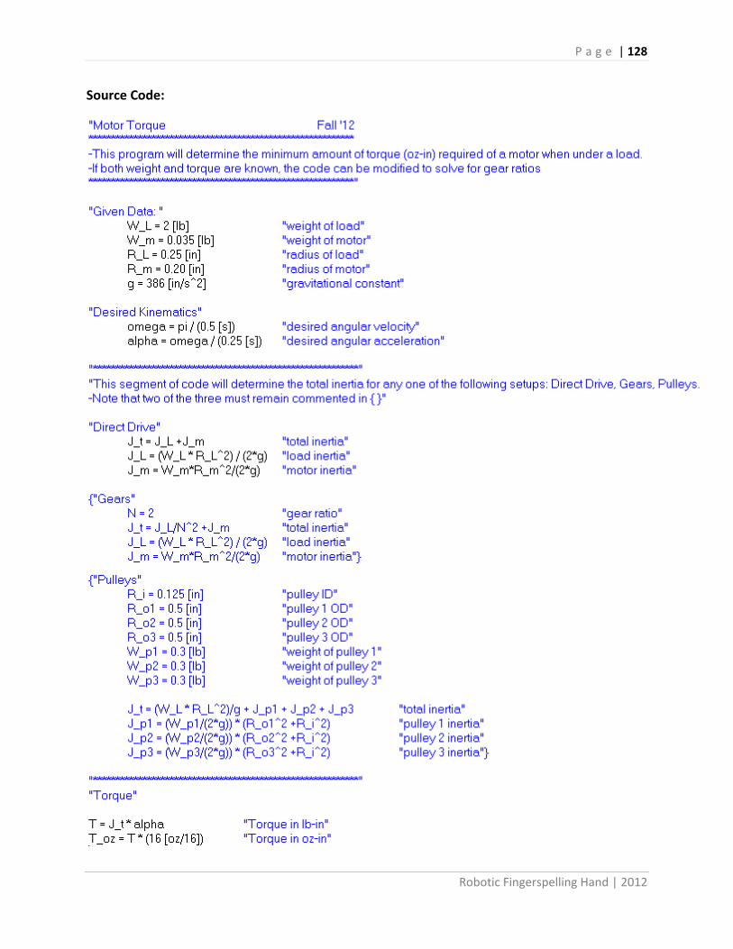
P a g e | 128
Robotic Fingerspelling Hand | 2012
Source Code:

P a g e | 129
Robotic Fingerspelling Hand | 2012
1988 Hand Anthropometric Excerpt
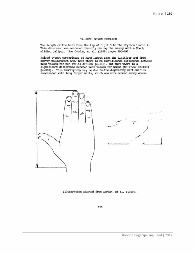
P a g e | 130
Robotic Fingerspelling Hand | 2012

P a g e | 131
Robotic Fingerspelling Hand | 2012

P a g e | 132
Robotic Fingerspelling Hand | 2012
Hand Shapes
A B
C D

P a g e | 133
Robotic Fingerspelling Hand | 2012
E F
G H

P a g e | 134
Robotic Fingerspelling Hand | 2012
I J (twist)
K L

P a g e | 135
Robotic Fingerspelling Hand | 2012
M N
O P

P a g e | 136
Robotic Fingerspelling Hand | 2012
Q R
S T

P a g e | 137
Robotic Fingerspelling Hand | 2012
U V
W X

P a g e | 138
Robotic Fingerspelling Hand | 2012
Y Z (twist)

P a g e | 139
Robotic Fingerspelling Hand | 2012
Installation:
1. Go to the Arduino website and hit the Download tab, or follow this link
http://arduino.cc/en/Main/Software
2. Download to your computer’s OS.
3. Go to the download location and unzip the file
4. Locate the .exe and double click it.
Example:
C:\ … \arduino-1.0.1-windows\arduino-1.0.1
Uploading files to the Arduino:
1. Plug the USB into the Arduino before connecting it to the computer
2. Open Arduino.exe
3. File Open [file name].ino
4. Click the right arrow on the GUI to upload the file
Installing Arduino files to Arduino:
Tuning:
NOTE: The tuning program tunes one finger at a time. The tuning order is: thumb index
middle ring pinky wrist and loops back to the thumb.
1. First, loaded up the degrees.ino to the Arduino.
2. Open terminal.exe
3. Engage the servos by pressing “g”.
4. “1” will decrement the angle of the knuckle servo by 5, which will bend the knuckle joint.
5. “2” will increment the angle of the knuckle servo by 5, which will straighten the knuckle
joint.
6. “3” will decrement the angle of the medial servo by 5, which will bend the medial joint.
7. “4” will increment the angle of the medial servo by 5, which will straighten the medial joint.
8. Record servo angle values that correspond with the angles in the #defines in
master_task.cpp

P a g e | 140
Robotic Fingerspelling Hand | 2012
9. Press “+” to tune the next finger or “-“ to tune the previous finger
Hand Program:
WARNING: The transistor that controls the power does not have the heat sink properly attached
due to space. Running the hand continuously for long periods of time will cause the transistor to
die. It is best to run it at most 2 minutes and let it cool down. To let it cool down, you can press "1",
"0" or the reset button. Even though when the hand is in the neutral position it is on, it is not
drawing any power so the transistor will still cool down.
1. First, loaded up the matrix_test.ino to the Arduino.
2. Once program is uploaded, you can control the hand using the terminal or just run the
demo.
3. To run demo, all you need to do is press the red demo button. The demo will spell through
the alphabet then turn off for a minute to allow the transistor to cool down. Then reengage
the servos and ready to use again.
4. To run real time, you will need to use the terminal.exe provided. In the textbox, you can
type sentences or words and then press enter for the hand to do the commands. The lower
box is for real time, so when you press a letter, the hand will immediately go to that letter.
Figure 28. Demo button to run the alphabet.

P a g e | 141
Robotic Fingerspelling Hand | 2012
Figure 29. The box highlighted in blue is the Textbox for typing in sentences and words. The box highlighted in red is the
Realtime box. When you enter a letter or command in here, the hand will do it immediately.