Robotic Arm for Dental Automation RADA
63
1 Robotic Arm for Dental Automation RADA Kevin Diola Jesus Manuel Garcia Enes Mentese Steve Ringor Jay Ryan Roldan Evan Von Lackum Andrew Wong CMPE/EE 123B Spring 2011
Transcript of Robotic Arm for Dental Automation RADA

1
Robotic Arm for Dental Automation
RADA
Kevin Diola
Jesus Manuel Garcia
Enes Mentese
Steve Ringor
Jay Ryan Roldan
Evan Von Lackum
Andrew Wong
CMPE/EE 123B
Spring 2011

2
Abstract
The Robotic Arm for Dental Automation (RADR) Project is a proof of concept project to explore
the applications of robotics in dentistry. The project will focus on designing a passive robotic
arm (PRA) that will be attached to a six degree of freedom (DOF) industrial robot, the Denso
robot. The passive arm along with a dental drill will be attached to the end effector of the
Denso robot. The passive arms’s end effector will be attached to a patient's jaw or tooth. The
passive robotic arm will sense the patient’s movement, sending feedback in the form of
translation and rotation data to the Denso robot giving it the capability to adjust. This device
will address the age-old problem in dentistry – precision and safety.
The Bionics lab at UCSC currently has a robotic system capable of dental drilling procedures on a
stationary object. The RADR project addresses the ability of the system to detect movement of
the object and accordingly adjust the drill before continuing the procedure. The RADR project
consists of two main parts: a passive robotic arm (PRA) and the electronics and software behind
the arm that detects motion. High resolution encoders at each joint of the PRA provide accurate
position and orientation data of the PRA’s tip (which is attached to the object). This data is
passed to the host computer where it is processed in order to the data in order to detect
movement of the object and adjust the drill.

3
Table of Contents
1. Project Overview ........................................................................................................ 5
2. Mechanical Design ..................................................................................................... 6
a) Passive Robotic Arm .................................................................................................... 6
b) Gripper ..................................................................................................................... 12
c) Enclosure .................................................................................................................. 14
3. Encoders & Line Receivers ........................................................................................ 17
a) Overview ................................................................................................................... 17
b) Selection process ...................................................................................................... 18
c) Line Receivers............................................................................................................ 18
d) PCB ........................................................................................................................... 19
4. Microcontoller .......................................................................................................... 19
a) Overview ................................................................................................................... 19
b) USART232 ................................................................................................................. 21
c) Software .................................................................................................................... 22
d) Quadrature Decoding ............................................................................................... 24
5. Power ....................................................................................................................... 26
6. Denso Control ........................................................................................................... 27
a) Forward Kinematics .................................................................................................. 27
b) Denso Robot & Host Software Interface ................................................................... 28
c) Denso Control ........................................................................................................... 29
d) Drill Control .............................................................................................................. 34
Appendix A: Block Diagram .......................................................................................... 37
Appendix B: Host Software .......................................................................................... 37
Appendix C: Forward Kinematics ................................................................................. 38
Appendix D: Budget ..................................................................................................... 39
Appendix E: Gantt Chart ............................................................................................... 41
Appendix F: Team Charter ............................................................................................ 42
Appendix G: Mechanical Drawings .............................................................................. 49

4
1. Project Overview a) Background The field of dental robotics is still in its infancy. It is a new area of research full of opportunities
with many applications. Some of its popular applications include haptic guided dental implants,
5
user controlled implant surgery using a virtual environment, and preoperative planning.
However, none of these applications involve total automation of the dental process. The area of
automatic robotic dentistry is very new and there is much to learn.
The Bionics Laboratory aims to explore this area by designing a prototype to automate dental
implant and drilling. Their current research effort has yielded the following:
• They were able to map human tooth using a 3D digitizer, the Miscroscribe MX, to create
a point cloud. This point cloud was converted to a Solidworks file to create a model of
the tooth. With this model, they were able to create a path for an industrial robot called
the Denso robot to drill on. After several test runs, they were able to successfully mill a
boundary around a tooth.
• In addition, they were able to control the movement of the Denso robot via
teleoperation using the Microscribe MX. By sending the six joint angles of the
Microscribe MX to the host computer and processing them, the Denso robot mirrors the
movement of the Microscibe MX.
These preliminary results proved that dental operations are achievable with the use of robots.
However, this prototype has areas for improvement that need to be addressed first. First, a
motion sensing device must be implemented to track patient movement. Second, an
appropriate robotic arm must be designed to replace the Denso robot.
b) Objective & Purpose The project is to design a passive robotic arm that will act as a guide and safety precaution for a
Denso robot that is used to automate dental drilling and implant surgery. The passive robotic
arm calculates the position and orientation of the patient's tooth and provides constant
feedback on the tooth's dynamic origin to the Denso robot. The passive robotic arm will
function as follows:
• Detect if there is patient movement. If movement is detected, stop the Denso robot's
current task and control the position and orientation of the Denso robot's end effector
based on the given position and orientation of the passive arm's end effector.
• The system must be able to turn on or off the dental drill if a movement is detected at a
specified tolerance level.
c) Specifications • Design a light weight passive robotic arm with 6 DOF that can determine position and
rotational orientation in space with .1mm accuracy or better
• Control the position and orientation of the Denso robot's end effector based on the
given position and orientation of the passive arm's end effector
• The device must be able to turn off the dental drill when a movement is detected
6
2. Mechanical Design a) Passive Robotic Arm Design Considerations
The passive robotic arm for this project was designed in SolidWorks, a computer aided design
program. SolidWorks enabled us to preview the entire mechanical system before anything was
physically made. This saved us time and allowed us to correct any mistakes or flaws in the
design without any drawbacks or major delays. After many minor revision, two major revisions,
and two final critical design reviews we had our final design of the passive robotic arm and
began the machining phase.
There were three main parameters of the passive robotic arm that had to be accounted for in
our design: mechanical strength, weight, and fluidity of the arm. Considering these parameters,
the materials chose to build our arm with play a crucial role in the arm’s functionality. Some
stationary parts of the arm such as the arm’s segments which gave the arm its length did not
have to be made out of metal, so we substituted much lighter carbon fiber tubes and only use
metal at the joints of the arm where the moving parts were. Minor adjustments like these
allowed us to bring down the total weight of the arm. As for the metal, we chose aluminum
6061 for its strength and lightweight characteristic. Aluminum is also relatively easier to
machine. Stainless steel was also used in the design but at a minimum. Stainless steel is much
stronger than aluminum but unfortunately also weighs more; so we kept its use to a minimum.
We used stainless steel for our joint’s shafts. The strength of the stainless steel shafts would
provide a more rigid design and would hold up against wear that might be caused from the
moving parts rubbing together over time. Fluidity is also very closely linked to strength and
lightness because if the arm is not strong it would bend and if they were not light it would be
massive and heavy, these two characteristics would then make it very difficult for the arm to
move fluidly. In addition, each joint would have a pair of high performance ball bearings in them
to allow the joints to move with ease and with minimum friction. A rotary encoder was
integrated to each joint in order to detect any movement within that joint. These rotary
encoders set parameters of how small our arm could be. The arm’s joints needed to be wide
enough to hold these encoders. The specifications of the high performance ball bears were also
based on the size of these encoders. The widest we could have the ball bearings without
increasing the size of the arm was as wide as the encoder was, and the wider the bearings, the
better. The arm has six joints with six degrees of freedom. The arm is passive so it does not have
any motors to control its movement; instead it has rotary encoders to monitor how much it
moves from the forces applied to the arm. Considering the passive arm’s purpose, designing it
in a way that minimizes rotating friction at the joints will provide the best results. The passive
robotic arm was also designed with modularity in mind. This allows the shafts, joints, and
encoders to easily be disassembled and changed for future improvements.
Joint Assembly
Parts that rotate in reference to other parts are very tricky to design, especially in this
application. The parts should only be able to move the way it is intended to move. In the case of

7
this application, a single joint on the passive arm should only be able to move about one axis.
Any flaw or imperfections in the design may result in wobble and play, which can accumulate
over the arm and translate into a positioning error at the end effector. Even a positioning error
of 1mm can be extremely detrimental considering the fact that an average human tooth is
about 6mm in width. To avoid wobble, we need a rigid design where mating parts have minimal
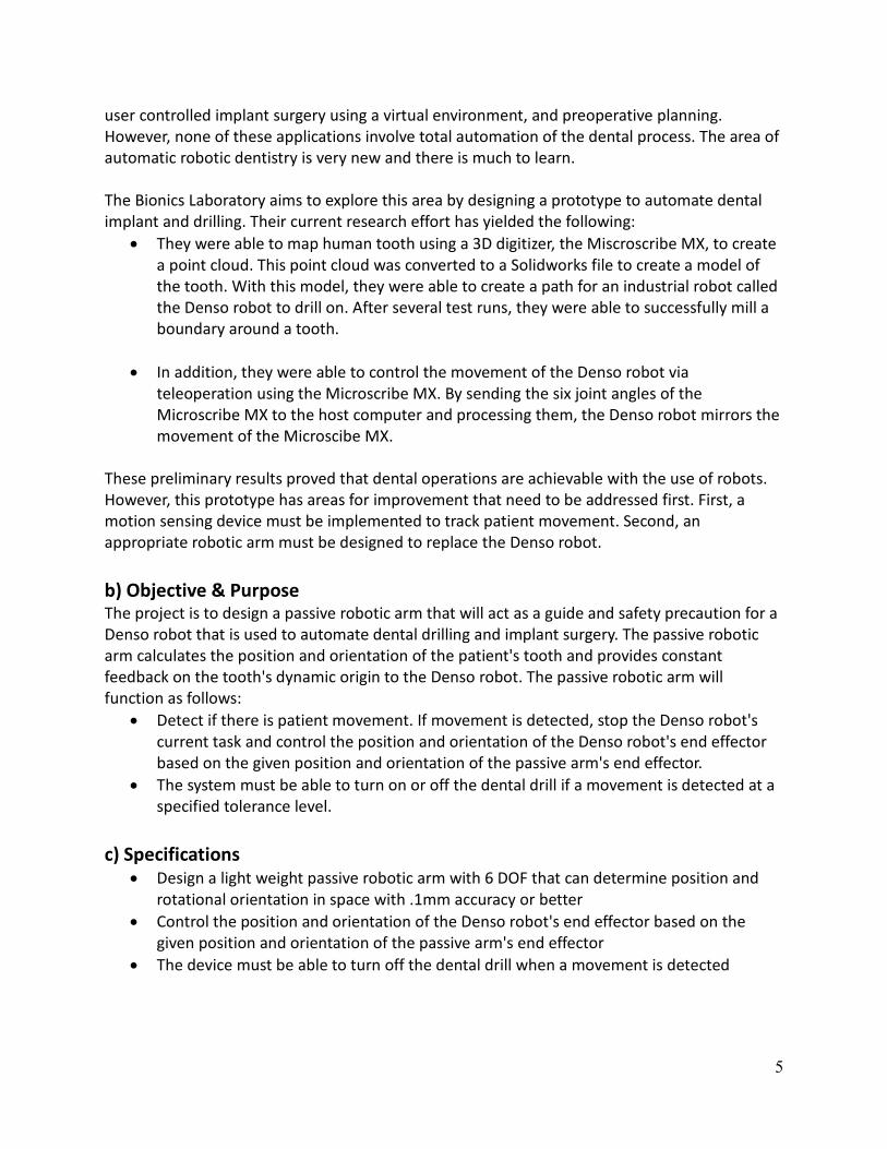
mechanical tolerances if any (press fitted). A sketch of the first joint assembly and its cutout are
depicted in figure 1 and a picture of the final product depicted in figure 2.
In the SolidWorks sketches, the green part is the shaft of the joint, the yellow part is the base
plate of the arm, the blue part is the piece that rotates about the shaft, the orange is the
encoder mounting stands, and finally the red part is the encoder. There are also two ball
bearings, a washer and a nut. The two ball bearings were pressed into the blue part from both
sides with a press fit of .001 inches, while the green shaft was press fitted into the yellow base
plate with a press fit of .003 inches. Getting the press fit right for the ball bearings was very
important because if the press fit was too heavy, in this case more than .001 inches, then the
Figure 1: SolidWorks drawings of the first joint asssembly
Figure 2: Joint 1
assembly final
product
8
ball bearings would be compromised and not spin properly due to the compression. To the
contrary the press fitting of the yellow and green could be heavier because they do not need to
rotate with respect to each other; essentially they become a single part. The reason why this
wasn’t machined as a single part was because the green is stainless steel and the yellow is
aluminum. Making the whole part out of aluminum would render the part too weak and making
the whole part out of stainless steel would render the part too heavy. This is why we did a mix
of the two so that we could get the characteristic of the stainless steel only in the areas that
bear a lot of the torque, which were the joint shafts.
The inner races of the ball bearings, however, were not press fitted to the green shaft in
consideration of modularity. Now the parts can be interchanged whereas if we had press fitted
them to the shafts it would have been a one-time deal. This did raise a new challenge though,
mainly that the blue part could now slip up and out the green shaft. In other words there was
nothing to hold it down. A retainer ring was considered for this task but was determined that it
was not strong enough and could not withstand the forces that would be applied to it. Also a
retainer ring’s position cannot be adjusted, requiring all the parts to have no mechanical
tolerances and to be perfect in their dimensions. On the other hand a simple nut would not
have this limitation and would withstand greater forces. A nut can also be adjusted to the actual
lengths and dimensions of the parts. This allows room for error without the tradeoff of
performance. After considering many options we realized that a simple nut would be the best
option. Fastening a nut down to the washer that rested on the inner race of the top ball bearing
sandwiched the entire joint assembly between the nut and the bearing lip of the green shaft.
This eliminated any potential wobble or play as well as kept the entire assembly rigid and
smooth. We had to be careful not to tighten the nut too much so as to not compromise the
functionality of the ball bearings and not to tighten them too little so as not allow room for
wobble or play. Unfortunately, a regular nut would not hold its position at the optimal
tightening point while the joint was moving. It would tighten and untighten depending on which
way the joint was moving. The main reason for this problem was because the nut was tightening
down on to a small surface area, the rim of the inner race of the bearing (with the washer in
between). We decided to use a nylon lock nut, which tightens down on the threads of a screw
instead. This allowed us to keep the nut stationary at the desired position while there was
movement in the joint.
The encoder mounting plates were a design challenge as well because they needed to hold the
encoder .240 inches above the top surface of the blue part while confined to the width of the
blue part. It had to take up very little space so that all the screws and nuts had clearance and
were accessible. There must not be any forces or strains felt by the encoder other than the
rotating motion of the shaft in order for it to produce the best results. For this reason it is
placed off to the side of the joint with minimal interference and interaction with the joint’s
movements. The encoder mounting stands were also designed with the consideration that the
encoder might need to move if there is any imperfections on the tip of the shaft leading into the
encoder. The encoder mounting stands were designed to flex in order to compensate for any
imperfections that might exist.

9
Passive Robotic Arm Assembly
The six joints on the passive robotic arm were all based on the same design as the first joint as
described above. However, each joint on the passive robotic arm is unique due to its individual
range of motion that allows the arm as a whole to achieve the desired unique positions. Figure
3 depicts the SolidWorks drawing and actual assembled arm.
Starting from the left, joint one, which is hidden inside a cylindrical shell, has a 360 degrees
range of motion. Joint two has a little more than 180 degrees of motion, joint three also has a
little more than 180 degrees of motion but its range is shifted so that the joint can fold into
itself where the two adjacent segments of the arm can be parallel to each other, whereas joint
two and five can’t achieve this. Joint 4 has 360 degrees of motion, joint 5 has 180 and joint six
has 360.
Machining Process of the Passive Robotic Arm
Machining all the parts of the passive robotic arm was a challenge, we had almost no machining
experience and the level of machining that was required was very advanced. It took more than
150 hours of machining time to complete all the parts. The machines that we had access too
were not very accurate or consistent so in order to make a part correctly we had to be very
patient and extremely careful. One of our parts got completely destroy when it was near
completion. Figure 4 displays all the parts of the arm before it was assembled.
Figure 3: SolidWorks drawing and actual assembled arm

10
Press fitting the ball bearings was also a challenge because each part that needed ball bearings
in it needed a ball bearing on both sides of it. This made it difficult because the ball bearing’s
inner races had to be completely concentric with each other so that the shaft would be able to
slip through them with ease, otherwise a concentric shaft would not be able to fit through both
ball bearings.
Final Product
Once all parts were completed and the arm was assembled, we built a stand to mount the
passive robotic arm to. This piece can be seen in figure 5.
Passive Robotic Arm Testing of ± 0.1 mm
The rotary encoders that we have are capable of detecting ± 0.1 mm with the setup and
configuration of the passive robotic arm. However, if there were any play in the passive robotic
arm’s structure, detection of ± 0.1 mm would be very difficult and inaccurate. For example, if
the arm’s structure has play of ± 0.1 mm then that means the arm can move ± 0.1 mm without
its movement being detected. So in order to test for this we have designed a block of aluminum
with two steps of roughly 0.1 mm difference in height from one step to the other (Figure 6).
Figure 4: All the parts of the arm prior to assembly
Figure 5: Assembled arm mounted to
stand, denso drilling robot in
background

11
The idea was to run the end effector of the passive robotic arm along the surface of this block
and when it steps down to the next step a difference of roughly 0.1 mm would be detected in
the corresponding axis depending on how the block was oriented.
Attachment Enhancement of Passive Robotic Arm to Patient
An attachment to a patient’s mouth was not part of our project and could be a whole new
project in itself. However, we did design a platform for researchers, who might continue this
project, to build on.
This piece clamps on to the end effector of the passive robotic arm and has an extending plate
that would go into the patient’s mouth (Figure 7). Presumably whoever picks up this project will
need to design a rigid and robust design of a method to attach this plate to the patient’s lower
and/or upper jaw.
Figure 6: Testing device for +/- .1mm accuracy
Figure 7: Piece for attachment to patient’s mouth
12
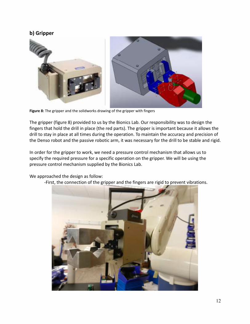
b) Gripper
Figure 8: The gripper and the solidworks drawing of the gripper with fingers
The gripper (figure 8) provided to us by the Bionics Lab. Our responsibility was to design the
fingers that hold the drill in place (the red parts). The gripper is important because it allows the
drill to stay in place at all times during the operation. To maintain the accuracy and precision of
the Denso robot and the passive robotic arm, it was necessary for the drill to be stable and rigid.
In order for the gripper to work, we need a pressure control mechanism that allows us to
specify the required pressure for a specific operation on the gripper. We will be using the
pressure control mechanism supplied by the Bionics Lab.
We approached the design as follow:
-First, the connection of the gripper and the fingers are rigid to prevent vibrations.

13
Figure 9: Denso robot with gripper and fingers attached
-Second, the matting of the drill and the fingers had the proper amount of force applied
by the gripper to prevent the drill from moving.
Figure 10: Two possible orientations of the drill
The design of the fingers gives the drill possible orientations.

14
Figure 11: Fingers constructed for the gripper
The gripper was an important part of this project; this what makes our project functional. When
implemented the gripper we made it versatile so we can allow our clients/users to hold other
mechanisms with the gripper.
c) Enclosure
Figure 12: Solidworks drawing of enclosure
The enclosure is where we have all the circuitry for our passive arm. For example, the

15
microcontroller, power circuits, and encoder circuits are all located inside the enclosure. We had
to design and build the enclosure.
When coming up with the design for the enclosure there are many issues we took into account.
Three major issues that we solved were noise on the signals, the characteristics of the
enclosure, and the accessibility of the electrical components.
Noise on the signals:
Achieving a low noise interference with our signals was the biggest issue with our enclosure
since we wanted .1mm accuracy. Noise was introduced to our signals by the Denso’s
mechanism. The signal to noise ratio equals (mean)/ (standard deviation) = . Also
environmental sources external to our system impacted the way our system function. For these
reasons, we had to consider noise reduction techniques and be aware to properly layout
components in our PCB design.
The following are types of noises we needed to consider:
• Environmental noise:
- This noise occurs because each conductor in the system is potentially an
antenna capable of picking up electromagnetic radiation and converting it to an
electrical signal.
- There are many sources of electromagnetic radiation in the environment;
Examples: AC power lines, radio stations, TV stations.
• Motor noise:
- Motor noise normally produces two types of noises: windage noise and
magnetic noise.
- Windage noise is generated by the interaction of moving parts, such as fans.
This noise is airborne and unlike magnetically generated noise, it does not
manifest itself as a structural vibration of the motors.
- Magnetic noise is usually cause by the interaction of electromagnetic flux waves
with the resonant frequencies of the stator core.
- Electromagnetic fields consist of various harmonics and it is not uniform in the
air gaps.
• Finally, vibration of sheet metal can also cause noise problems.
- The metal sheets can cause vibration noise when the system has to move fast.

16
Figure 13: Enclosure for PRA
The characteristics of the enclosure:
The enclosure was made from lightweight material alloy 3003. We selected aluminum
3003 because it has very good corrosion resistance and strength. Also aluminum 3003 had a
price that fit our budget and our wanted density/weight. We ended up paying $14.10 for a
.063” thickness x 12” x 24” alloy 3003 compare to aluminum 6061, the next lightweight alloy,
$21.13 for a .062” thickness x 12” x 12”. Even though 6061 is better in density (.098 pounds per
cubic inch (lb/cu.in) ), we could still use alloy 3003 with a density of .099 lb/ cu.in, (data in figure
14).
The enclosure needed to be lightweight because of the load limitation of the connection
point where the passive robotic arm would be attached to the Denso robot. Another
characteristic for the enclosure was the dimensions. The dimensions were limited to the space
provided on the Denso robot but it needed to be big enough to contain all the electrical
components, top picture (The enclosure and Denso).
Figure 14
Accessibility of the electrical components:
Modularity and accessibility of the electrical components were taking into consideration, as
well. There are two parts to the enclosure; the bottom part attaches to the Denso (picture
below label Bottom part) and the top cover holds all the electrical components, power circuits,
encoder circuits, and micro-controller (picture below label Top part). The thinking that went
began the design was the following. If we had connected the components to the bottom part

17
like every other enclosure it would have been hard to remove the enclosure from the Denso.
You would have to unscrew the top cover then remove the PCB and micro and then you would
remove the bottom part. However, the way we designed it you unscrew the top cover and you
bring with you all the electrical components leaving the bottom part attach to the Denso.
Another unique update to the enclosure is that the components in the top cover are upside
down. So, when it’s unscrew the components appear upright. This update makes it easer to
troubleshoot the micro or any circuitry.
Figure 15: Top (left) and bottom (right) parts of the enclosure
The enclosure was built to help our system have clear signals, protect our circuits, and make it
easier for us to troubleshoot.
3. Encoders A) Overview
Encoders are used at each joint to enable us to calculate joint angles that are later used in the
forward kinematics. The encoders we used are optical rotary relative encoders. Too enhance the
performance of the encoders we sent the differential encoder signals thrrough line recievers
that provided us with a more relaible signal. We also used a quadrature encoding algorithm to
get the max number of pulses per revolution out of our encoders, this algorithm is explained in
depth later in the report. Since the encoders are relative their absoulute position and direction
must be hard coded into the micro and accounted for in calibration.

18
B) Selection Process
Selecting the encoder was critical in that we needed to get the ±0.1 mm accuracy.
There were three critical constraints for the encoders for this project.
The first constraint was that the encoder needed a resolution to get us that ±0.1 mm
accuracy.
We also had a size constraint on the encoder. We needed the encoder to be < 1 in2.
Since the encoders will be placed on the arm, we needed them to be small enough so
that the arm won’t be very bulky.
Finally, a price constraint was needed. This is a senior design project with limited
funding. Taking that fact into account, we wanted the price to be < $300.00. We felt
this was feasible enough to find an encoder with a high enough precision for this
project.
With these constraints in mind we used AEDA-3300 Series encoders. These are optical
incremental encoder modules. When emitting an LED light, a high-
precision codewheel rotates and produces analog signals. These analog signals are
then processed into digital signals: A, B, and I, as well as their complements: !A, !B, !I.
A oscilloscope view of signals A and B (the signals we needed) are in figure XXX.
C) Line Receivers
The datasheet recommends that we use quad differential line receivers to buffer the signals
from the encoders. Below is a basic overview of the system. I pulled this from the encoder
datasheet.
Figure 16: An oscilloscope view of
of signals A and B. Every edge of
either signal is counted. These
particular signals would cause our
quad decoding software to count
in one direction 12 times. If an
edge of A or B comes twice in a
row before an edge of the other
the count switches direction

19
The schematic describes the encoder signals to the line receiver transferred by a ribbon cable.
The encoders use the analog signals and convert them into digital signals. It then uses a line
driver to output these signals. We then need to use a line receiver to buffer these signals. The
signals most likely will contain noise, so we can filter this out using the correct line receiver.
The line receiver that we used was the AM26LV32IPW. The most important aspect of this
receiver is that it accepts 5-V Logic inputs with a 3.3-V supply. This also means that it outputs
3.3-V signals, which is compatible with the noise margin of the microcontroller. The output
signals of the line receivers have around a 2-ns rise time and were negligible when adding them
into our latency contraints.
D) PCB
The PCB contains the line receivers to buffer the signals from the encoders and pins to send
these signals to the microcontroller. It also contains the power circuit, as well as the drill control
circuit.
Bill of Materials
Quantity Part
2 0.33 uF 0805 Caps
8 0.1 uF 0805 Caps
1 Schottky Diode
11 2-pin Headers
12 100 Ω 0603 SM resistors
3 1K Ω 0603 SM resistors
1 2K Ω 0603 SM resistor
1 470 Ω 0603 SM resistor
1 7805 Linear Regulator (5-V)
1 7833 Linear Regulator (3.3-V)
3 AM26LV32IPW (Line Receivers)
1 7620-E
1 MCP6041
1 TS5A3166
Figure 17: This is the
recommended line receiver circuit
from the encoder/line drive to the
line receiver. This helped us
determine the design of our
system from the arm to the
microcontroller.

20
Another note about the PCB layout was that the transmission lines from the pin headers had a
constraint since they were differential signals. They both needed to be the same length to have
the same time delay, as well as have a trace width constraint. I picked microstrip transmission
lines for the differential signals. The spacing between each line could be at most 5 mils. The
width of them was 26 mils for a 100 Ω transmission line. Each set of differential transmission
lines were then terminated at the line receiver with a 100 Ω resistor.
4. Microcontroller a) Overview The microcontroller that we used to interface the encoders, drill and host computer of the is the
STM32F107 from STMicroelectronics. The characteristics of the STM32F107 microcontroller that
are important for our project are as follows:
- Core: ARM 32-bit Cortex-M3 CPU
- 72 MHz maximum frequency, 1.25 DMIPS/MHz (Dhrytone 2.1)
- Single-cycle multiplication and hardware division
- Memories
- 64 to 256 Kbytes of Flash memory

21
- up to 64 Kbytes of SRAM
- Clock, reset, and Supply Management
- 2.0 to 3.6 V application supply and I/Os
- 3 - to - 25 MHz crystal oscillator
- 2 x 12-bit D/A converters
- Up to 80 fast I/O ports
- 51/80 I/Os, all mappable on 16 external interrupt vectors and almost all 5 V-tolerant
- Communication Interfaces:
- 14 communication interfaces
- Up to 5 USARTs (ISO 7816 interface, LIN, IrDA capability, modem control)
- USB OTG
- CRC calculation unit, 96-bit unique ID
A picture of the microcontroller and its evaluation board from Micrium is shown in figure 17.
Figure 18: STM32F107 Evaluation Board
The reason we incorporated the STM32F107 in our design is because its core processor the
ARM 32-bit Cortex-M3 provides a low-cost platform with a reduced pin count and low-power
consumption, while delivering outstanding computational performance and an advanced
system response to interrupts.
The Arm Cortex-M3 core possesses a nested vectored interrupt controller (NVIC) that is able to
handle up to 67 maskable interrupt channels and 16 priority levels. It supports stacking
(nesting) of interrupts, allowing an interrupt to be serviced earlier by exerting higher priority.
Interrupts that are being serviced are blocked from further activation until the interrupt service
routine is completed; so their priority can be changed without risk of accidential re-entry.
22
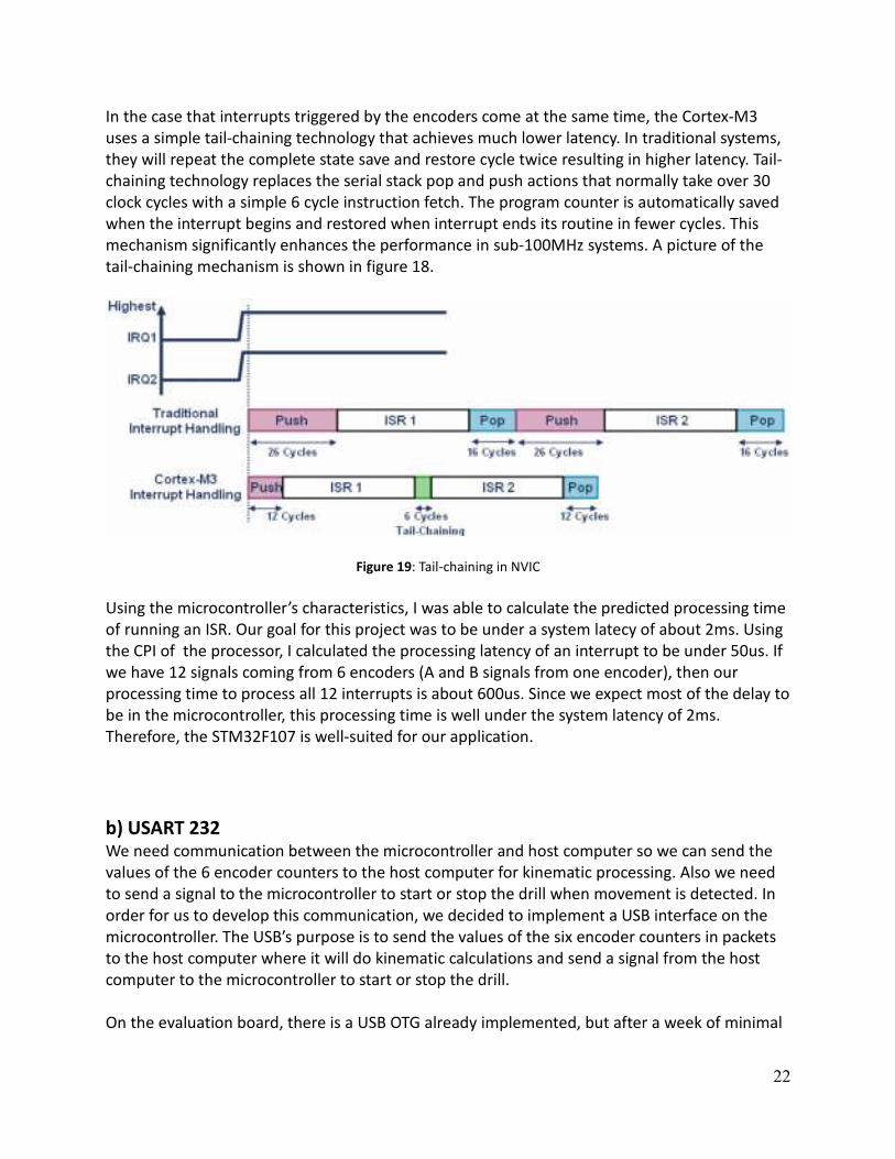
In the case that interrupts triggered by the encoders come at the same time, the Cortex-M3
uses a simple tail-chaining technology that achieves much lower latency. In traditional systems,
they will repeat the complete state save and restore cycle twice resulting in higher latency. Tail-
chaining technology replaces the serial stack pop and push actions that normally take over 30
clock cycles with a simple 6 cycle instruction fetch. The program counter is automatically saved
when the interrupt begins and restored when interrupt ends its routine in fewer cycles. This
mechanism significantly enhances the performance in sub-100MHz systems. A picture of the
tail-chaining mechanism is shown in figure 18.
Figure 19: Tail-chaining in NVIC
Using the microcontroller’s characteristics, I was able to calculate the predicted processing time
of running an ISR. Our goal for this project was to be under a system latecy of about 2ms. Using
the CPI of the processor, I calculated the processing latency of an interrupt to be under 50us. If
we have 12 signals coming from 6 encoders (A and B signals from one encoder), then our
processing time to process all 12 interrupts is about 600us. Since we expect most of the delay to
be in the microcontroller, this processing time is well under the system latency of 2ms.
Therefore, the STM32F107 is well-suited for our application.
b) USART 232 We need communication between the microcontroller and host computer so we can send the
values of the 6 encoder counters to the host computer for kinematic processing. Also we need
to send a signal to the microcontroller to start or stop the drill when movement is detected. In
order for us to develop this communication, we decided to implement a USB interface on the
microcontroller. The USB’s purpose is to send the values of the six encoder counters in packets
to the host computer where it will do kinematic calculations and send a signal from the host
computer to the microcontroller to start or stop the drill.
On the evaluation board, there is a USB OTG already implemented, but after a week of minimal

23
progress, we decided to use the USART on the microcontroller and buy a product that converts
USART signals into differential signals for the USB. The vendor called Future Technology Devices
Internation (FTDI) specializes in converting peripherals to Universal Serial Bus (USB). They sell IC
bridge chips that implement the conversion. As a result, we bought a cable that composes of
the IC bridge chip and a RS232 level shifter on the USB connector. This cable is shown in figure
19.
Figure 20: USB-RS232 Serial Converter Cable
After assigning the converter cable a port and downloading the driver off of FTDI’s website, we
can send our encoder counter values through this cable and send a signal to start or stop the
drill.
c) Software Here is a list of .c files that we developed for our application:
main.c
This is our main file that initializes the following applications:
- Reset and Clock Control
- General Purpose Input/Output Pins
- Nested Vectored Interrupt Controller

24
- External Interrupts
- Digital Analog Converter
- USART
- Window Watchdog
After initializing these applications, the program will continuously transmit the encoder counter
values through the RS232 port, receive the drill status from the host computer, and reset the
watchdog counter when it reaches a specific limit.
usartapp.c
This file composes of our USART application. The following functions are needed to make the
USART operational:
int inc(int c)
- used to increment to the next buffer
void USART2_IRQHandler()
- interrupt service routine for the USART where it transmits/receives data.
void WriteData()
- send the contents of one write buffer to the data register where it transmits data to the host
computer
uint8_t Drill_Control()
- receives the status of the drill control from the host computer which is stored into the first
read buffer
InitUSART()
- initializes the following variables:
- initialize the baud rate to 9600
- set wordlength to 8 bits
- set to one stop bit
- no parity
- sets receive and transmit mode
- disables flow control
- set USART clock and interrupt pin
failurerecovery.c
This file composes of the window watchdog. The window watchdog is used to detect software
faults usually generated by external interference or by unforeseen logical conditions. This
causes the program to abandon its normal procedure. The following functions are developed to

25
implement the window watchdog.
void WWDGInit(void)
- configures WWDG clock, sets watchdog timeout to 4ms, and enables WWDG interrupt
void CheckWindow(void)
- resets the WWDG counter after 4ms
stm32f10x_encd.c
This file handles the interrupts that are triggered by the encoders and appropriately counts each
time one is triggered, explained in more detail later in the report.
stm32f10x_concat.c
This file’s purpose is to divide a 16 bit number into two 8 bit numbers. This is due to our USART
read/write buffer handling only 8 bits of information at a time. This file is composed of two
functions:
uint8_t CounterXA(uint16_t countx)
- receives 16 bits of encoder counter and returns the first 8 bits of the encoder counter
uint8_t CounterXB(uint16_t countx)
- receives 16 bits of encoder counter and returns the last 8 bits of the encoder counter

26
Figure 21: Microcontroller Software Block Diagram
d) Quadrature Decoding Why Quadrature Decoding?
Our encoders provide increment signals that go high 7200 times during a revolution, but this
was not enough for our purpose. Using quadrature decoding we could get 4 times the counts
per revolution; this was essential for the accuracy of our project. Figure 21 shows an
oscilloscope image of 3 increment count, but 12 quadrature decoding counts.

27
This algorithm is used to decode the two signals, A and B, coming from the encoders into counts
that are later translated to angles. This algorithm is contained on the microcontroller and uses
12 interrupts (2 for each encoder) that are triggered on both the negative and positive edge.
The algorithm is essentially a state machine implemented six times (once for each encoder); the
high level state machine diagram is shown in figure XXX.
The actual code contains six sets of four variables: Status, Dir, Count, and Up.
Status (boolean): true when interrupt A was the last interrupt triggered, false when interrupt B
was the last interrupt triggered
Dir (boolean): true when direction of count needs to be changed, false when direction of count
doesn’t need to be changed
Up (boolean): true when count direction is up, false when count direction is down
Count (int): keeps track of count (between 0 and 27799)
A more complex software flow diagram is shown in figure 22.
Figure XXX.
Figure 22: An oscilloscope view of
of signals A and B. If quadrature
decoding was not used this would
provide us with three counts. With
quadrature decoding this enabled
us to see 12 counts for these
particular signals.

28
Figure 23: Flow char of data for quadrature decoding algorithm
5. Power Our system is powered by a Mean Well AC wall adapter that outputs 9V and is able to supply
1.66A. This wall adapter was chosen because we needed to satisfy two requirements: provide
enough input voltage for the standard linear voltage regulators and provide enough current for
all our components. Standard linear voltage regulators require ~2V dropout voltage. Using the
reverse polarity protection diode, the voltage at the regulator input will be 8.3V which enables
allows more than the required 2.0V dropout voltage. In order to choose the wall adapter we
also needed to make sure that it would be able to supply the required 1.12A, calculated in our
power budget below. This adapter can provide up to 14.94W of power, which is more than
enough for our system.
The voltage from the adapter will be dropped down using standard linear voltage regulators to
provide the components with a 5V and 3.3V voltage rail. We chose to use standard regulators,
as opposed to low drop out regulators, because stability of the regulator is less reliant on the
capacitance and equivalent series resistance values of the output capacitors. Efficiency is also
not one of our requirements and the AC adapter can supply the required dropout voltage for
the standard regulators. For the 5V voltage rail, we used a STM L7805ABV because it can handle
current outputs of up to 1.5mA, which is required because the encoders and development
board require about 1.1A. For the 3.3 voltage rail, we used the Texas Instruments UA78M33 to
output 3.3V and supply up to 500mA.

29
Figure 24: Mean Well 9Vdc 1.66A AC Adapter
Component Quantity Voltage
Supply [V]
Maximum Current
Draw [mA]
Power
Encoders 6 5.0V 100 mA 3 W
Development Board 1 5.0V 500 mA 2.5 W
CMOS Analog Switch 1 5.0V 0.1 µA 0.55 µW
Line Receivers 3 3.3V 20 mA 198 mW
Total Power 5.698 W
Total Current 1.12 A
Figure 25: Power Budget
6. Denso & Host Software a) Forward Kinematics Overview
Forward kinematics are equations that describe the position and orientation of the tip of a
robot relative to its base. The variables in the equation are the joint angles and the constants
are link lengths (distances from joint to joint). Forward kinematics are commonly used to
control robotic arms, though are control method is different since the forward kinematics of our
arm is controlling another arm (the Denso robot).
Devin-Hartenburg (DH) Parameters
ai-1: the distance from Zi-1 to Zi measured along Xi
αi-1: the angle from Zi-1 to Zi measured about Xi
di: the distance from Xi-1 to Xi measured along Zi
θi: the angle from Xi-1 to Xi measured about Zi
Transform Matrices
•••• A transform matrix describes the position of jointi relative to jointi-1 as well as the
rotation of axisi with respect to axisi-1 (figure 25)

30
Figure 26: Transform matrix as computed form DH parameters
•••• One transform matrix for each joint and one more for tip
•••• When the transform matrices are multiplied together in order starting with the
transform for the first joint the position and orientation of the tip of the robot is
described relative to the base
•••• Our DH parameters and shown in figure
i ai-1 αi-1 θi di
1 0 0 θ1 d1
2 0 -90 θ2 0
3 a2 0 θ3 0
4 a3 -90 θ 4 d4
5 0 90 θ 5 0
6 0 -90 θ 6 0
7 a6 0 0 d7
Figure 27: DH parameters for PRA, a’s and d’s are adjustable with carbon fiber tube lengths
b) Denso Robot and Host Software Interface The software on the host computer was developed using Visual Basic. The choice of using Visual
Basic was based on the latency and available classes and libraries. We tested Visual Basic’s
latency by coding matrix calculations of kinematics equations and tested how long it took to
finish the calculations. Our results yielded an average of .5usec. In terms of available libraries,
Visual Basic contains built in functions for multithreading and serial communications.
The Denso robot uses Programming Language for Assembly Cell (PAC) to describe and program
robot motion and work. To interface the host software with the Denso robot, we used a
middleware called Orin2. Orin2 is a middleware that offers a standard interface for various
resources including robots. Orin2 is composed of a Controller Access Object (CAO) technology
that enables the user to access robot interface from client applications like Visual Basic.

31
Since the PAC programming is running separately from the Visual Basic program in the host
computer, we had to develop a synchronization protocol between the two software blocks. The
Denso robot has local variables that reside inside the RC7M robot controller, position and
integer variables. By using the Orin2 SDK to interface the two software blocks and access
variables between the two blocks, we used these variables to synchronize processes of the PAC
and visual basic language. We used the integer variables as flags to trigger various functions or
processes and we used the position variables to contain position and orientation command
information for the Denso robot. Figure 26 depicts a diagram of how the Denso and host
software interfaces.
Figure 28: Host and denso block diagram
c) Denso Control The Denso control aspect of the project pertains to algorithms that will control the repositioning
and reorientation of the Denso robot. This will include patient movement algorithm and
repositioning and reorientation algorithm. While the Denso robot performs dental tasks (e.g.
dental implant or crowning tasks), the PRA will constantly feedback the patient movement to
the host computer. If movement is detected, the tasks will pause, stops the drill, and repositions
and reorients the Denso robot, before resuming the procedure.

32
Figure 29: Control flow diagram
From the microcontroller, binary raw data will be sent to the host computer via a USB port.
These binary raw data will be converted to ASCII characters and converted to usable angles. The
kinematics block accepts six joint angles from the Binary to ASCII conversion block and
calculates the PRA’s position and orientation. Both the Motion Detection Block and Demo Task
Block will accept this position and orientation data.
The Motion Detection Block detects if the end effector of the PRA moved. For the PRA attached
to Denso configuration, the base of the PRA will also be moving with the end effector of the
Denso, so the algorithm will start by calculating the transformation matrix of the PRA and Denso
( by multiplying the Denso transform (
, the offset ( ,and the PRA transform (
.
Then compare the previous transformation matrix of the PRA and Denso ( to the current
transformation matrix of the PRA and Denso ( ′ ). Movement is detected if current is not
equal to previous transform ( .

33
Figure 30: Motion Detection with PRA attached to Denso
For the tabletop configuration of the PRA, motion detection was accomplished by just
comparing the previous PRA transform ( to the current PRA transform (
′.
Figure 31: Motion Detection with PRA at tabletop configuration
The Denso task block reads position via points on a text file that contains a task (e.g. dental
drilling or implant surgery), looks for a motion detect flag and also sets the drill enable and
disable command. When there is no motion detected, its function is to just read position via
points and calls the SendVar() function which purpose is to send these via points to the Denso.

34
When the motion detect flag is high, however, it disables the drill, calls Adjust() function to
readjust the target location of the Denso, sets an integer variable within PAC language to
activate the adjust process, and stops reading position via points until the Denso reaches the
target location.
Figure 32: Denso task flow diagram
These two blocks will have to be constantly running, monitoring the motion of the PRA and
updating the movement of the Denso robot from the specified task. To accomplish this, both
blocks are placed on separate threads and Visual Basic’s multithreading library of classes and
functions is used. This has several advantages. First, it frees processor time and enables it to
process two tasks at once. Secondly, the intensive calculations and decision making processes
can be done in the background while the user interface is free to be used by the user
Raw Data Conversion
Input: Counts in binary
Output: Joint angles in ASCII
Function: Accepts binary raw data from the USB and converts them to joint angles in ASCII
Designer: Evan Von Lackum
Kinematics
Input: Joint angles
Output: Position(x,y,z) and Orientation(rx,ry,rz) of PRA
Function: Calculates the kinematics equations of the PRA
Designer: Evan Von Lackum
Motion Detection Algorithm
Input: Position(x,y,z) and Orientation(rx,ry,rz) of PRA, and Position(x,y,z) and Orientation(rx,ry,rz)
of Denso robot
Output: Motion detect flag with current position(x,y,z) and orientation(rx,ry,rz) of PRA, and drill

35
control enable signal
Function: For the PRA attached to the Denso, it constantly compares the position(x,y,z) and
orientation(rx,ry,rz) of PRA to the position(x,y,z) and orientation(rx,ry,rz) of Denso robot to
detect patient movement. For the tabletop configuration, it constantly compares the current
and previous position (x, y, z) and orientation (rx, ry, rz) of PRA. A motion detect flag will
produce a new origin for the Denso robot, disable the drill control signal and enable sleep mode
of the Dental task.
Designer: Jay Roldan
Denso Tasks
Input: Via points of Denso robot
Output: Denso robot position(x,y,z)
Function: Controls the path of the Denso robot to perform actual dental drilling tasks or any
other operations.
Designer: Jay Roldan
Denso Position/Orientation Control
Input: Position(x,y,z) and orientation(rx,ry,rz) of PRA.
Output: Position and orientation of Denso in PAC language
Function: During normal operation, this block specifies the Denso robot path and orientation
based on the PRA’s position and orientation (the origin). Performs reorientation and
readjustment of the Denso path when motion detect flag is enabled. This block will be in PAC
language.
Designer: Jay Roldan
Denso Control Block in PAC
Denso control in PAC language has 3 cases, Home, Adjust, and Traverse.
Home – takes the set home position and move the Denso to that location.
Adjust – takes the current PRA location and moves the Denso to that location. The current PRA
location will also be stored so that it will be the reference movement of the Denso when
performing dental tasks.
Traverse – takes the specified path to traverse during operation and moves the Denso to that
location. All movement are in reference to PRA location.
We used the following local variables within the Denso controller:
PAC Local variables used:
I0 = designates which control case to take (Home, Adjust, Traverse)
I1 = read enable flag for Visual Basic. Signifies movement complete.
P0 = contains position variable for movement OR current position
P1 = contains PRA position variable

36
P2 = contains Denso path position variable
P98 = contains the home position variable
I0 and I1 are integer variables used to access tasks processes and acts as flags. P0-P2 and P98
are position variables. Position variables are composed of seven items, the first three are the
position vector (x, y, and z) in millimeter, the second three are the orientation vector (rotation
on the x, y, and z axis) in degrees, and the last item is the figure, which specifies what the figure
of the Denso robot. This figure must be maintained on every movement of the Denso to avoid
locking up the Denso robot.
d) Drill Control The drill controller allows the host computer to start, stop, and adjust the speed of the dental
drill. This is used to prevent drilling while the Denso arm is adjusting its position. One drill
used for general purpose drilling is the Nakanishi NSK Z500. Since this drill controller is
expensive we were able to borrow one from the Bionics Lab. Therefore we treated this external
drill controller as a black box and try to replicate the signals that are inputted into the controller.
The NSK Z500 comes with the Nakanishi FC40 foot pedal, for the dentist to vary the speed using
their feet. To operate the drill controller, the user first needs to set the maximum speed of the
drill from 0-40000rpm. Depending on how hard the pedal is pushed the speed of the drill will
vary from 0rpm to the maximum speed set.
Figure 33: Nakanishi NSK Z500 Dental Drill Controller w/ FC40 Foot Pedal
To allow the host computer to control the drill we replicate the signals coming from the pedal
into the NSK Z500. The drill’s pedal consists of two parts, a mechanical switch and a
potentiometer. The pedal is then connected to the Z500 via a cable consisting of four wires.
The potentiometer is connected across two wires from the drill controller; call it the speed pins.
The drill controller keeps the current through the potentiometer at a constant 0.1mA. As the
pedal vary the resistance, the voltage across the two pins change. This adjusts the speed of the
drill. The switch is connected across the other two pins from the drill controller; call it the
on/off pins. This switch is used to turn on and off the drill. When the drill is off, the switch is
open causing the voltage across the on/off pins to be 5V and the resistance across the
potentiometer is 50kΩ, which corresponds to 5V across the speed pins. When the drill is on,

37
the switch is closed, causing the voltage across the on/off pins to be 0V. The resistance across
the potentiometer is 0Ω, which corresponds to 0V across the speed pins. While the switch is
closed the varying resistance of the potentiometer causes the voltage across the speed pins to
vary, which in turns changes the speed of the drill.
Figure 34: Original drill control block diagram
Drill Status Switch Setting Potentiometer Speed Pin Settings
On (Max Speed) Closed 0kΩ 0V
On (Intermediate Speed) Closed 0-50kΩ 0-5V
Off Open 50kΩ 4.5-5V Figure 35: Drill control parametes
To replicate the mechanical switch we used a CMOS Analog switch IC, which allows the switch to
open and close depending on the voltage on the input pin of the IC. This IC allows the
microcontroller to easily toggle a switch on the on/off pins by toggling the output of a GPIO pin
in push-pull output mode.
To vary the speed we came up with three options. The first option is to use a digital
potentiometer that is controlled by the microcontroller through SPI. We looked into using a
Microchip MCP41 digital potentiometer. This digipot acts like a regular potentiometer with
three pins; two connected across a resistor and one wiper that connect one end of a resistor to
an intermediate position across the resistor. The second option is to use a DAC to create a
varying voltage across the speed pins. A third option is to have the drill on at its maximum
speed setting and using the NSK Z500 to change the maximum speed which adjusts the current
speed of the drill.
In order to decide which option to implement we looked at some advantages and disadvantages
of each. Of the three, the digital potentiometer is the most similar to the actual pedal but is the

38
most complicated to implement. It would also cause the most latency because it requires
transferring data through SPI. Using the digipot would require sending data from the host to
the microcontroller then from the microcontroller to the digipot. On the other hand using the
DAC would only require receiving data from the host and the microcontroller would change the
output of the DAC by writing to the DAC data register. Considering the tradeoffs of each option
we decided to choose a combination of the second and third option. Since the demo document
did not mention varying the speed, we only needed the DAC to output 0V or 3.3V to turn on
and off the drill. Varying the speed of the drill can be done by varying the maximum speed
while the drill is on.
The 3.3V would then need to be amplified to 5V in order stop the drill. To amplify the output
voltage of the D/A converter we used an operational amplifier in a non-inverting amplifier
configuration to create a gain of 1.5. Since we only have 3.3V and 5V power rails we used a
Microchip MCP6041, which is a rail-to-rail output op amp. This allows 4.7V to be applied across
the speed pins to force the drill to its lowest speed and stop by opening the switch.
Figure 36: Emulated drill control block diagram

39
Appendix A: Block Diagram
Appendix B. Denso Control Software
Denso Control (PAC Language)
PROGRAM radr_ttop1 takearm changework 0 DEFPOS targetloc P[0] = CURPOS P[1] = CURPOS LET P2 = (0,0,0,0,0,0) LETF P98 = CURFIG WHILE I0 > 0 'LOOP INF WEND while i0 <5 if i0 = 0 then ' home LETF P98 = CURFIG MOVE P, P98 P[0] = CURPOS LETP targetloc = pvec(p98) 'let home = reference LETR targetloc = rvec(p98) LET P[1] = (0, 0, 0, 0, 0, 0) 'RESET P1 LET i0 = 4 'exit home LET i1 = 1 'open read command endif

40
if i0 = 2 then 'PATH LET P5 = CURPOS LETF P1 = CURFIG LETP targetloc = PVEC(p1)'pra position LETR TARGETLOC = rvec(P1) '+ rvec(P5) 'absolute rotation LetF targetloc = CURFIG LETF P2 = CURFIG LETR P0 = RVEC(targetloc) LETP P0 = PVEC(targetloc) + PVEC(P2) 'ONLY POSITION MOVE L, P0 LETP P0 = (0, 0, 0) 'RESER POS OF P0 LETR P[1] = (0, 0, 0) 'RESET P1 LETP P2 = (0, 0, 0) LET I0 = 4 'exit home LET i1 = 1 'open read command endif wend END
Appendix C: Forward Kinematics DH parameters
i ai-1 αi-1 θi di
1 0 0 θ1 d1
2 0 -90 θ2 0
3 a2 0 θ3 0
4 a3 -90 θ 4 d4
5 0 90 θ 5 0
6 0 -90 θ 6 0
7 a6 0 0 d7

41
`
`
•••• T01 stands for transfor from base to joint1
•••• T67 stands for transfor from joint 6 to the tip
•••• Multiplying all of these matrices togerther gives you the transform between the base and
the tip (I don’t add these equations because they are extremely long and their calculation
is simple)
Appendix D: Budget
SUBSYSTEM COMPONENT QTY PRICE ($) COST ($)
Sensor System
Encoders (30K
PPR) 12 150 1800
Counters 12 25 300

42
Shielded Cable N/A 20 20
Subtotal 2120
Microcontroller Microcontroller 4 25 100
Dev Kit 1 200 200
Subtotal 300
Power
Plug-in AC
Adapter 1 50 50
Regulators and
Ics N/A 45 45
H-Bridge 4 5 20
Discrete
Components N/A 100 100
Subtotal 215
System Layout PCB 3 100 300
Gripper Materials N/A 25 25
Enclosure
Materials N/A 45 45
Connectors and
Fasteners N/A 50 50

43
Appendix E: Gantt Chart

44
Appendix F: Team Charter
Robotic Arm for Dynamic Registration (RADR)
CMPE/EE 123 A&B Winter/Spring 2011 Group Website: https://sites.google.com/a/slugmail.ucsc.edu/passive-robotic-arm/home
Group Email: [email protected]
Members:
Mission Statement:
Our aim is to explore the applications of robotics in dentistry by designing a passive robotic arm
for dental automation with improved precision and safety. Our operating values are to execute
and elevate timeless “working together” principles, promote and maintain a team culture of
trust, and strive for excellence in all we do.
Project Definition:
The project is to design a passive robotic arm that will act as a guide and safety precaution for a
Denso robot that is used to automate dental drilling and implant surgery. The passive robotic
arm calculates the position and orientation of the patient's tooth and provides constant
feedback on the tooth's dynamic origin to the Denso robot. This is a proof of concept project to
explore the application of robotics in dentistry.
Andrew Wong
EE - Electronics
415 359 8713
Steve Ringor
CMPE – Digital Hardware
805 233 0079
Jesus Manuel Garcia
CMPE – Digital Hardware
831 707 5482
Jay Ryan Roldan
CMPE – Robotics and Control
415 706 7276
Enes Mentese
EE – Electronics
510 637 9132
Kevin Diola
CMPE – Digital Hardware
408 705 7208
Evan Von Lackum
BE – Bio-electronics
415 847 8152

45
Specifications:
− Design a passive robotic arm with 6 DOF that can determine position and rotational
orientation in space with .1mm accuracy or better.
− The passive robotic arm must be lightweight at the end effector.
− Control the position and orientation of the Denso robot's end effector based on the
given position and orientation of the passive arm's end effector.
− The device must be able to turn on or off the dental drill if a movement is detected.
− The output needs to interface with the current Visual Studio program
Optional Specifications:
− Create a UI that will setup the the device, the drill, and the Denso robot
• Improve speed of delay.
Division of Labor:
Mechanical Sub-Team
Enes Mentese
Enes is the Team Leader of the Mechanical Sub-Team. He is responsible for tracking the detailed
sub-plan of the sub-team, monitoring results, and facilitating and setting up meetings of the
sub-team as necessary.
Enes is also the lead engineer on Mechanical Design of the Passive Arm. He will design the
Passive Arm in Solidworks and lead the prototyping and machining process. For a successful
design, the integration of sensors to the Passive Arm and cable management will be considered
in his design process. Having taken the Mechatronics class, he will assist in the system layout
and implementation of noise reduction techniques.
Mechanical Design (Passive Arm):
Mechanical Design of Passive Arm
Research and Selection of Materials
Passive Arm Prototyping
Bend and Torque Tests
Sensor Integration to Passive Arm
Cable Management
Evan Von Lackum
Evan is the team Treasurer. His responsibilities include managing the team budget, parts
purchasing, and creating Bill of Materials (BOM).
Evan is also the lead engineer on Kinematics. He will be heavily involved in the beginning phase
of the design process, researching and calculating the requirements and specification of the
mechanical design which will be the baseline for the Mechanical Design Engineer. He will also
be responsible in any kinematics calculations and programming in the project.

46
Kinematics:
Kinematics Calculations and Programming
Determine Requirements and Specifications of Passive Arm
Encoder specifications and selection
Accuracy Analysis
Arm Calibration
Jesus Manuel Garcia
Jesus is the team Secretary. He will be responsible for documentation during the meeting,
creating minutes, and posting updates on the group website.
Jesus is also the lead engineer on Mechanical Design of Enclosure and Gripper. He will design an
enclosure for the electrical systems of the Passive Arm and a gripper for the drill. He will also
constantly coordinate with the Electronics Sub-Team for the proper layout of electrical systems,
taking into consideration noise reduction techniques.
Mechanical Design (Enclosure and Gripper):
Mechanical Design of Enclosure and Gripper
Research and Selection of Materials
Enclosure and Gripper Prototyping
Rigidity and Vibration Tests
System Layout
PCB Layout
Software and Electronics Sub-Team
Kevin Diola
Kevin is the Team Leader of the Software and Electronics Sub-Team. He is responsible for
tracking the detailed sub-plan of the sub-team, monitoring results, and facilitating and setting
up sub-team meetings as necessary.
Kevin is also the lead engineer on Electronics and Sensors. He will build and test sensor circuits
for the encoders, and program the micro-controller to translate sensor raw data to usable
angles. Kevin will also be responsible for creating a user interface (buttons, LEDS, indicators) for
the Passive Arm.
Electronics and Sensors:
Passive Arm User Interface
Sensor Circuit
Signal Conditioning and Processing
Sensor Testing
Counter Design
Encoder State Machine
Sensor Power Budget

47
Andrew Wong
Andrew is the lead engineer on Drill Control and Power. He will determine the power
requirements of the system, design and build a power system unit, and integrating power
budget of each systems. In addition, Andrew will design and build a drill control circuit including
creating libraries for the drill control which include speed control.
Drill Control and Power:
Drill Control Circuit
Drill Control
speed control
Power Regulation and Distribution
Power System Schematics
Integrated Power Budget
Steve Ringor
Steve is the lead engineer on Micro-Controller. His responsibilities include setting the software
for the micro-controller, setting the interfaces for other components, and ensures that the
system has failure recovery. He will oversee any task that involves micro-controller
programming.
Micro-Controller:
Research and Selection of Micro-controller
Set-up Micro-controller Software
Set-up Interface for other components
Failure Recovery
Micro-controller Power Budget
Jay Ryan Roldan
Jay is the Project Manager of the RADA Team. He will be responsible for coordinating activities
of the team, setting up team meetings, keeping the production schedule, and driving the team
to meet the final project goal.
Jay is also the lead engineer on Software and Denso Control. His main responsibility is to control
the Denso Robot based on the movement of the Passive Arm. In addition, he will make sure that
every software part of the project is working properly.
Software and Denso Control:
Denso Control
Denso Calibration
Denso Task Demo Program
Software Troubleshooting and Debugging
State Machine
Software Block Diagram
Code of Conduct:

48
Meetings
Meetings will be held at least once a week. Agenda for the meeting will be drafted by the
Project Manager with inputs from the team and will be posted online at Passive Robotic Arm
Google Groups. Members are expected to have read any updates on the team website. During
the meeting, each member are expected to update the team on their progress and
communicate any problems encountered. Members are also expected to take notes. At the end
of the meeting, notes will be collected by the Secretary to create a meeting minutes and will be
posted online. Those who will not be able to attend the meeting will have to notify the group at
least 24 hours ahead of time via email. Unexpected tardiness must be reported to their
respective team leaders.
Client Updates
A team representative will meet with the client each week to report team progress. The client
will be informed on any critical changes or problems ahead of time.
Time Commitment
Each team member is required to work at least 30 hours per week in lab. If a member does not
have an assigned task they can work on, he must find ways to help out other members of the
team. If deadline can not be met, members must inform the team ahead of time and propose a
new deadline which will be decided by the team.
Budget
The Treasurer will be responsible for running the team budget. Any purchases using the team
budget must be reported to the Treasurer. Purchases in excess of 25 dollars must be discussed
by the team.
Documentation
Team members are expected to maintain excellent documentation of their work. A team binder
will be made available in the lab at all times that contains schematics, design drawings,
application notes, datasheets, and the likes. Each member will be responsible in maintaining
this binder. All pertinent documents will also be posted online by the team Secretary.
Decision Making and Dispute Resolution
Any critical changes on the project must be decided by the team. The decision must be
unanimous to take effect.
Any dispute will be handled as a group. A team member consistently missing meetings, not
meeting deadlines 50% of the time, not meeting the minimum work contribution (working in
lab 30hrs/wk), or constant disputes with other team members will be subject for termination.
The decision process for termination is as follows:
• A team meeting will be generated, and the individual(s) involved will present their case
to the team. The team will present resolutions and notify the professors. The team
member will then be given a chance to redeem themselves by actively contributing in
the project process, excellent work ethic, and meeting the minimum time commitment

49
as stated above. After a week, the team will decide if the offending member(s) has met
the expected minimum requirements. If not, a voting process will take place to decide
termination. A majority vote of 4 of 6 will result in termination pending approval from
the Instructors.

50
We have read and agree to abide by the guidelines set forth in the Robotic Arm for Dental
Automation Project Charter.
Steve Ringor: _______________________ Date: ___________________
Andrew Wong: _______________________ Date: ___________________
Evan Von Lackum: _______________________ Date: ___________________
Jesus Manuel Garcia: _______________________ Date: ___________________
Kevin Diola: _______________________ Date: ___________________
Enes Mentese: _______________________ Date: ___________________
Jay Ryan Roldan: _______________________ Date: ___________________

51
Appendix G: Mechanical Drawings

52

53

54

55

56

57

58

59

60

61

62

63