RobotC I2C Interface Tutorial Storming Robots Packet … RobotC Tutorial... · then x contains 5,...
25
Storming Robots Computational Thinking and Engineering For Kids 1 | Page RobotC I2C Interface Tutorial RobotC-I2C Interface Packet Scope: This tutorial will show steps to interface with I2C sensors. Before we go into programming to I2C interfaces, there are a few things you should have a fair amount of knowledge, or at least know what they represent: Data structure – “struct” and “array” (this should been introduced in the Programming Packet II) Bits / hexadecimal representation. (in this document) What is a Memory Address? What is a bus? (in this document) Table of Contents
-
Upload
truongquynh -
Category
Documents
-
view
221 -
download
0
Transcript of RobotC I2C Interface Tutorial Storming Robots Packet … RobotC Tutorial... · then x contains 5,...
Storming Robots
Computational Thinking and Engineering For Kids
1 | P a g e
RobotC I2C Interface Tutorial
– Packet II
R o b o t C - I 2 C I n t e r f a c e P a c k e t
Scope: This tutorial will show steps to interface with I2C sensors.
Before we go into programming to I2C interfaces, there are a few things you should have a fair amount of
knowledge, or at least know what they represent:
Data structure – “struct” and “array” (this should been introduced in the Programming Packet II)
Bits / hexadecimal representation. (in this document)
What is a Memory Address? What is a bus? (in this document)
Table of Contents
Storming Robots
Computational Thinking and Engineering For Kids
2 | P a g e
RobotC I2C Interface Tutorial
– Packet II
Storming Robots
Computational Thinking and Engineering For Kids
3 | P a g e
RobotC I2C Interface Tutorial
– Packet II
CH1 – LEARNING ABOUT BITS & BYTES
CH1 – 1 BINARY & HEXADECIMAL BASED
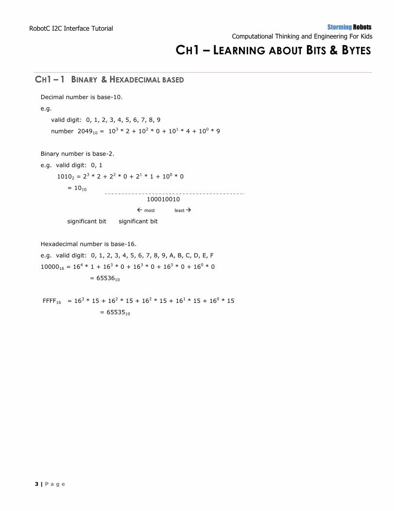
Decimal number is base-10.
e.g.
valid digit: 0, 1, 2, 3, 4, 5, 6, 7, 8, 9
number 204910 = 103 * 2 + 102 * 0 + 101 * 4 + 100 * 9
Binary number is base-2.
e.g. valid digit: 0, 1
10102 = 23 * 2 + 22 * 0 + 21 * 1 + 100 * 0
= 1010
100010010
most least
significant bit significant bit
Hexadecimal number is base-16.
e.g. valid digit: 0, 1, 2, 3, 4, 5, 6, 7, 8, 9, A, B, C, D, E, F
1000016 = 164 * 1 + 163 * 0 + 163 * 0 + 163 * 0 + 160 * 0
= 6553610
FFFF16 = 163 * 15 + 162 * 15 + 162 * 15 + 161 * 15 + 160 * 15
= 6553510
Storming Robots
Computational Thinking and Engineering For Kids
4 | P a g e
RobotC I2C Interface Tutorial
– Packet II
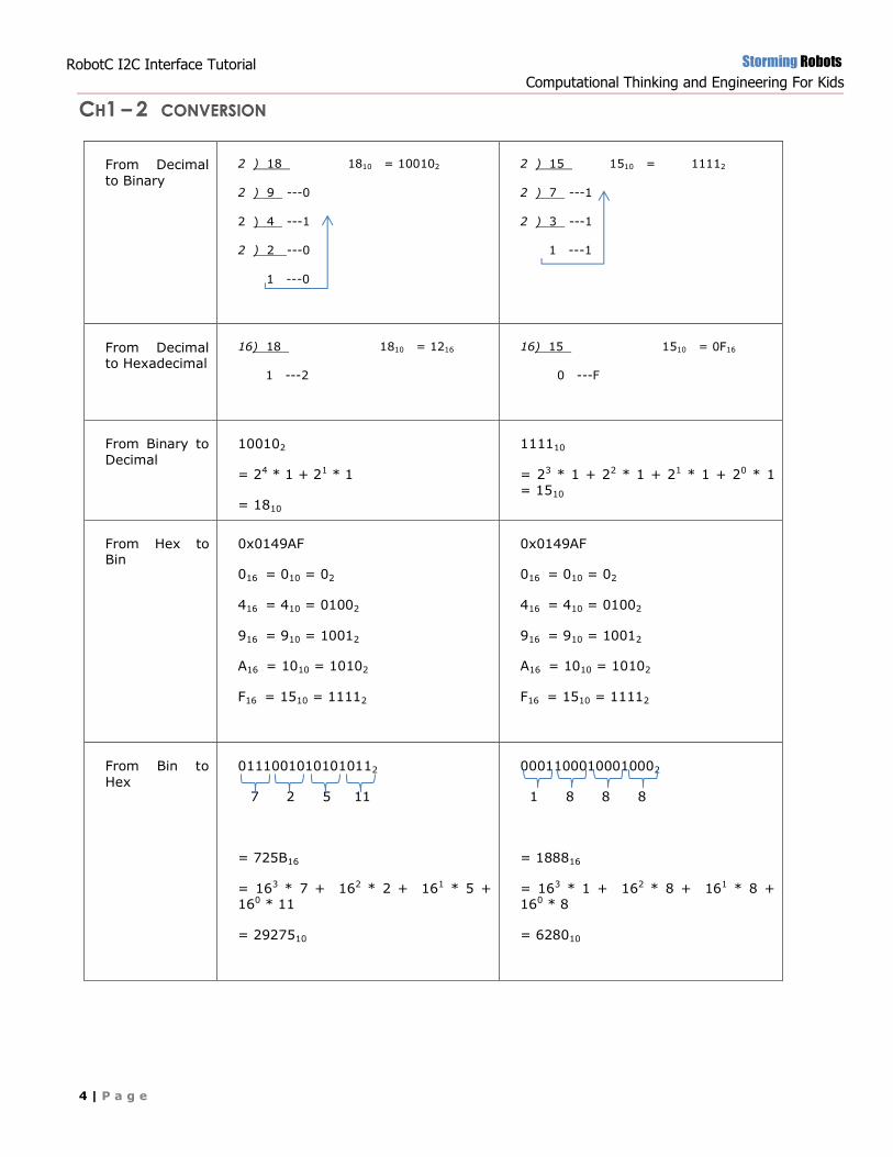
CH1 – 2 CONVERSION
From Decimal
to Binary
2 ) 18 . 1810 = 100102
2 ) 9 ---0
2 ) 4 ---1
2 ) 2 ---0.
1 ---0
2 ) 15 . 1510 = 11112
2 ) 7 ---1.
2 ) 3 ---1.
1 ---1.
From Decimal to Hexadecimal
16) 18 . 1810 = 1216
1 ---2
16) 15 . 1510 = 0F16
0 ---F
From Binary to
Decimal
100102
= 24 * 1 + 21 * 1
= 1810
111110
= 23 * 1 + 22 * 1 + 21 * 1 + 20 * 1 = 1510
From Hex to Bin
0x0149AF
016 = 010 = 02
416 = 410 = 01002
916 = 910 = 10012
A16 = 1010 = 10102
F16 = 1510 = 11112
0x0149AF
016 = 010 = 02
416 = 410 = 01002
916 = 910 = 10012
A16 = 1010 = 10102
F16 = 1510 = 11112
From Bin to
Hex
01110010101010112
7 2 5 11
= 725B16
= 163 * 7 + 162 * 2 + 161 * 5 + 160 * 11
= 2927510
00011000100010002
1 8 8 8
= 188816
= 163 * 1 + 162 * 8 + 161 * 8 + 160 * 8
= 628010
Storming Robots
Computational Thinking and Engineering For Kids
5 | P a g e
RobotC I2C Interface Tutorial
– Packet II
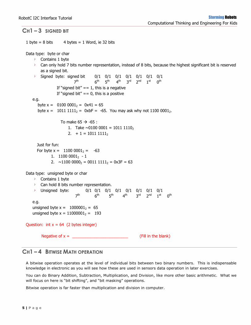
CH1 – 3 SIGNED BIT
1 byte = 8 bits 4 bytes = 1 Word, ie 32 bits
Data type: byte or char
Contains 1 byte
Can only hold 7 bits number representation, instead of 8 bits, because the highest significant bit is reserved
as a signed bit.
Signed byte: signed bit 0/1 0/1 0/1 0/1 0/1 0/1 0/1
7th 6th 5th 4th 3rd 2nd 1st 0th
If “signed bit” == 1, this is a negative
If “signed bit” == 0, this is a positive
e.g.
byte x = 0100 00012 = 0x41 = 65
byte x = 1011 11112 = 0xbF = -65. You may ask why not 1100 00012.
To make 65 -65 :
1. Take ~0100 0001 = 1011 11102
2. + 1 = 1011 11112
Just for fun:
For byte x = 1100 00012 = -63
1. 1100 00012 - 1
2. ~1100 00002 = 0011 11112 = 0x3F = 63
Data type: unsigned byte or char
Contains 1 byte
Can hold 8 bits number representation.
Unsigned byte: 0/1 0/1 0/1 0/1 0/1 0/1 0/1 0/1
7th 6th 5th 4th 3rd 2nd 1st 0th
e.g.
unsigned byte x = 10000012 = 65
unsigned byte x = 110000012 = 193
Question: int x = 64 (2 bytes integer)
Negative of x = _________________________ (Fill in the blank)
CH1 – 4 BITWISE MATH OPERATION
A bitwise operation operates at the level of individual bits between two binary numbers. This is indispensable
knowledge in electronic as you will see how these are used in sensors data operation in later exercises.
You can do Binary Addition, Subtraction, Multiplication, and Division, like more other basic arithmetic. What we
will focus on here is “bit shifting”, and “bit masking” operations.
Bitwise operation is far faster than multiplication and division in computer.
Storming Robots
Computational Thinking and Engineering For Kids
6 | P a g e
RobotC I2C Interface Tutorial
– Packet II
Operator: |
Function: set bits on
e.g. x = 0102; y = 1112, x = x | y, i.e. x == 1112
Operator: &
Function : find out which particular bit(s) is/are set.
e.g. x = 0102; y = 1112, x = x & y, i.e. x == 0102
e.g. x = 1112; y = 1012, x = x & y, i.e. x == 1012
Operator: ^
Function: set bits off or switch bit on& off
e.g. x = 0102; y = 1112, x = x ^ y, i.e. x == 1012
e.g. x = 1012; y = 1012, x = x ^ y, i.e. x == 02
e.g. x = 1; y = 1; x = x^y; i.e. x==0 // great to be used as an on/off switch
e.g. x = 0; y = 1; x = x^y; i.e. x==1
Operator: ~
Function:, is a unary operation that performs logical negation on each bit
e.g. x = 0102; ~x == 1012
e.g. x = 1; ~x == 0 // great to be used to alternate on/off state
e.g. x = 0; ~x == 1
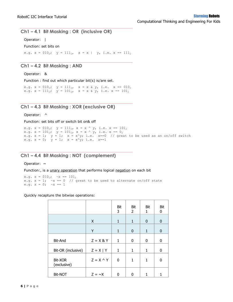
Quickly recapture the bitwise operations:
Bit 3
Bit 2
Bit 1
Bit 0
X 1 1 0 0
Y 1 0 1 0
Bit-And Z = X & Y 1 0 0 0
Bit-OR (inclusive) Z = X | Y 1 1 1 0
Bit-XOR (exclusive)
Z = X ^ Y 0 1 1 0
Bit-NOT Z = ~X 0 0 1 1
Ch1 – 4.1 Bit Masking : OR (inclusive OR)
Ch1 – 4.2 Bit Masking : AND
Ch1 – 4.3 Bit Masking : XOR (exclusive OR)
Ch1 – 4.4 Bit Masking : NOT (complement)
Storming Robots
Computational Thinking and Engineering For Kids
7 | P a g e
RobotC I2C Interface Tutorial
– Packet II
Caution! Do not use bit shift unless you FULLY aware of the signed and unsigned relationship, as well as binary
math operation. If you have to use it, you should write a separate program to test out all signed and signed
situation to ensure you will not have shifting errors.
CH1 – 5 BIT-SHIFT OPERATION
Operator : <<
Function: multiple by 2n
e.g. x = 1010 * 2 1; i.e. 10102 << 1
then x contains 20 , i.e 101002
e.g. x = 1010 * 2 2; i.e. 10102 << 2
then x contains 40 , i.e 1010002
Operator : >>
Function: divided by 2n
e.g. x = 1010 / 2 1; i.e. 10102 >> 1
then x contains 5, i.e 1012
e.g. x = 1010 / 2 2; i.e. 10102 >> 2
then x contains 2, i.e 102 (note that not 2.5 because this is supposed to deal with “int” data type, not float)
CH1 – 6 MORE ON BITS MATH FOR PERFORMANCE
In modern computer architecture, multiplication and division have been optimized to the point that it performs
just as good as bits operation. The only one which will still be faster with bit math is calculating X^n, instead of
using power(X, n).
Pseudo code for doing your power X^n:
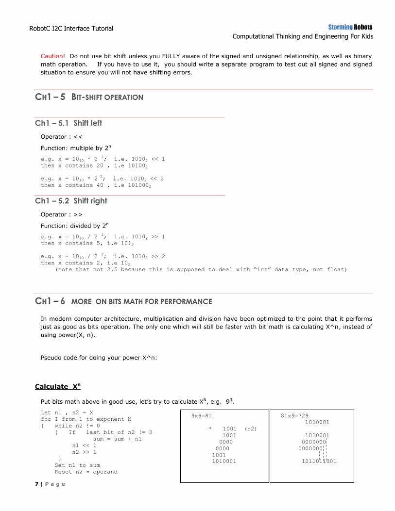
Calculate Xn
Put bits math above in good use, let’s try to calculate XN, e.g. 93.
Let n1 , n2 = X
for I from 1 to exponent N
{ while n2 != 0
{ If last bit of n2 != 0
sum = sum + n1
n1 << 1
n2 >> 1
}
Set n1 to sum
Reset n2 = operand
Ch1 – 5.1 Shift left
Ch1 – 5.2 Shift right
9x9=81
1001 (n1)
* 1001 (n2)
1001
0000
0000
1001 .
1010001
81x9=729
1010001
X 1001
1010001
0000000
0000000
1010001 .
1011011001
Storming Robots
Computational Thinking and Engineering For Kids
8 | P a g e
RobotC I2C Interface Tutorial
– Packet II
}
CH1 – 7 EXERCISE:
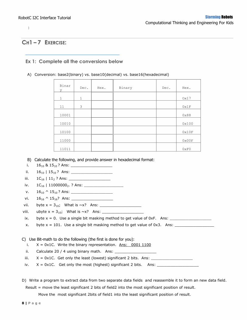
Ex 1: Complete all the conversions below
A) Conversion: base2(binary) vs. base10(decimal) vs. base16(hexadecimal)
Binar
y Dec. Hex. Binary Dec. Hex.
1 1 Ox17
11 3 0x1F
10001 0x88
10010 0x100
10100 0x10F
11000 0x00F
11011 0xF0
B) Calculate the following, and provide answer in hexadecimal format:
i. 1610 & 1510 ? Ans: __________________
ii. 1610 | 1510 ? Ans: __________________
iii. 1C16 | 112 ? Ans: __________________
iv. 1C16 | 110000002. ? Ans: _________________
v. 1610 ^ 1510 ? Ans: __________________
vi. 1616 ^ 1516? Ans: __________________
vii. byte x = 310; What is ~x? Ans: __________________
viii. ubyte x = 310; What is ~x? Ans: __________________
ix. byte x = 0. Use a single bit masking method to get value of 0xF. Ans: __________________
x. byte x = 101. Use a single bit masking method to get value of 0x3. Ans: _________________
C) Use Bit-math to do the following (the first is done for you):
i. X = 0x1C. Write the binary representation. Ans: 0001 1100
ii. Calculate 20 / 4 using binary math. Ans: __________________
iii. X = 0x1C. Get only the least (lowest) significant 2 bits. Ans: __________________
iv. X = 0x1C. Get only the most (highest) significant 2 bits. Ans: __________________
D) Write a program to extract data from two separate data fields and reassemble it to form an new data field.
Result = move the least significant 2 bits of field2 into the most significant position of result.
Move the most significant 2bits of field1 into the least significant position of result.
Storming Robots
Computational Thinking and Engineering For Kids
9 | P a g e
RobotC I2C Interface Tutorial
– Packet II
e.g.
If int field1 = 0xdb02
int field2 = 0x1f06
then int result should be = 0x1011
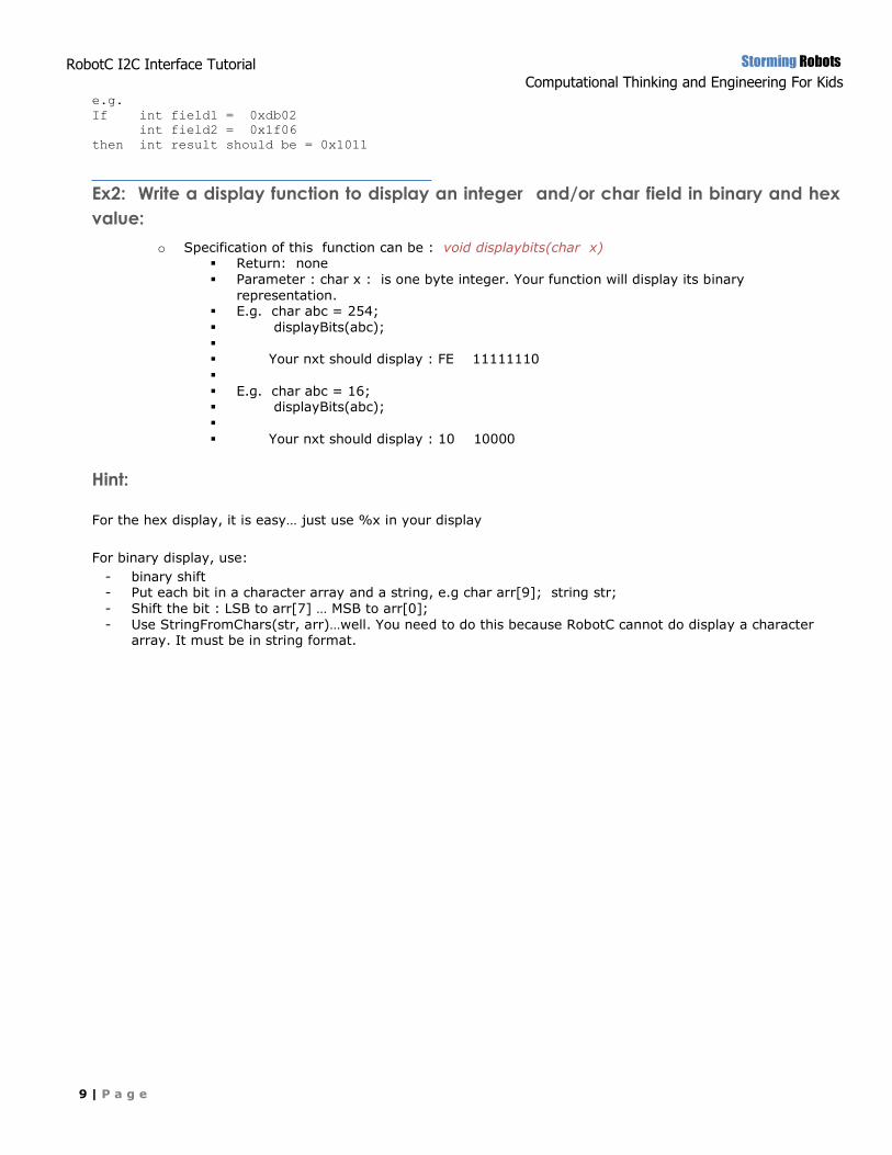
Ex2: Write a display function to display an integer and/or char field in binary and hex
value:
o Specification of this function can be : void displaybits(char x) Return: none
Parameter : char x : is one byte integer. Your function will display its binary
representation. E.g. char abc = 254;
displayBits(abc);
Your nxt should display : FE 11111110
E.g. char abc = 16; displayBits(abc);
Your nxt should display : 10 10000
Hint:
For the hex display, it is easy… just use %x in your display
For binary display, use:
- binary shift - Put each bit in a character array and a string, e.g char arr[9]; string str;
- Shift the bit : LSB to arr[7] … MSB to arr[0];
- Use StringFromChars(str, arr)…well. You need to do this because RobotC cannot do display a character array. It must be in string format.
Storming Robots
Computational Thinking and Engineering For Kids
10 | P a g e
RobotC I2C Interface Tutorial
– Packet II
CH2 – SET AND ACCESS I2C PORTS
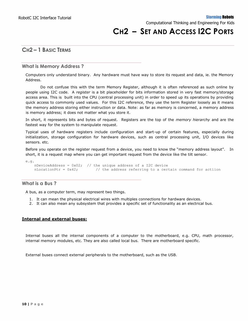
CH2 – 1 BASIC TERMS
Computers only understand binary. Any hardware must have way to store its request and data, ie. the Memory
Address.
Do not confuse this with the term Memory Register, although it is often referenced as such online by
people using I2C code. A register is a bit placeholder for bits information stored in very fast memory/storage
access area. This is built into the CPU (central processing unit) in order to speed up its operations by providing
quick access to commonly used values. For this I2C reference, they use the term Register loosely as it means
the memory address storing either instruction or data. Note: as far as memory is concerned, a memory address
is memory address; it does not matter what you store it.
In short, it represents bits and bytes of request. Registers are the top of the memory hierarchy and are the
fastest way for the system to manipulate request.
Typical uses of hardware registers include configuration and start-up of certain features, especially during
initialization, storage configuration for hardware devices, such as central processing unit, I/O devices like
sensors. etc.
Before you operate on the register request from a device, you need to know the “memory address layout”. In
short, it is a request map where you can get important request from the device like the tilt sensor.
e.g.
nDeviceAddress = 0x02; // the unique address of a I2C device
nLocationPtr = 0x42; // the address referring to a certain command for actiion
A bus, as a computer term, may represent two things.
1. It can mean the physical electrical wires with multiples connections for hardware devices. 2. It can also mean any subsystem that provides a specific set of functionality as an electrical bus.
Internal and external buses:
Internal buses all the internal components of a computer to the motherboard, e.g. CPU, math processor,
internal memory modules, etc. They are also called local bus. There are motherboard specific.
External buses connect external peripherals to the motherboard, such as the USB.
What is Memory Address ?
What is a Bus ?
Storming Robots
Computational Thinking and Engineering For Kids
11 | P a g e
RobotC I2C Interface Tutorial
– Packet II
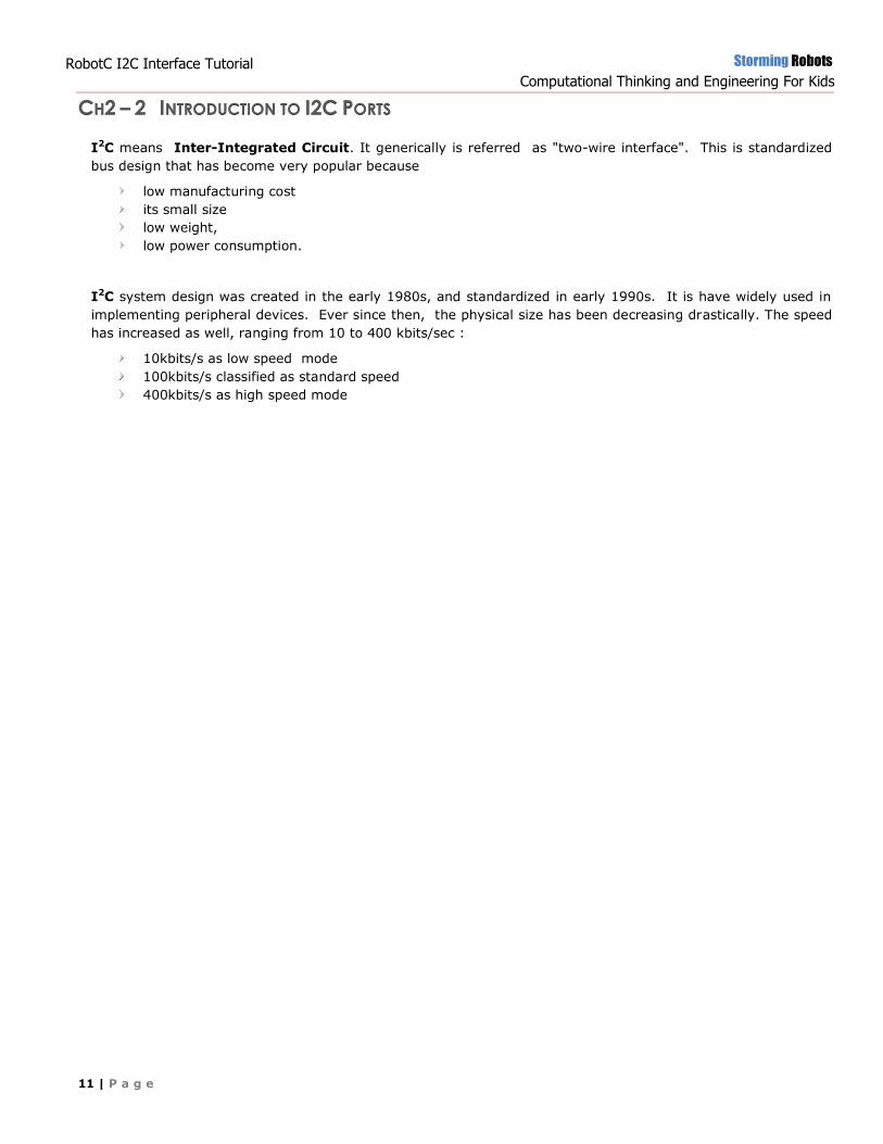
CH2 – 2 INTRODUCTION TO I2C PORTS
I2C means Inter-Integrated Circuit. It generically is referred as "two-wire interface". This is standardized
bus design that has become very popular because
low manufacturing cost
its small size
low weight,
low power consumption.
I2C system design was created in the early 1980s, and standardized in early 1990s. It is have widely used in
implementing peripheral devices. Ever since then, the physical size has been decreasing drastically. The speed
has increased as well, ranging from 10 to 400 kbits/sec :
10kbits/s as low speed mode
100kbits/s classified as standard speed
400kbits/s as high speed mode
Storming Robots
Computational Thinking and Engineering For Kids
12 | P a g e
RobotC I2C Interface Tutorial
– Packet II
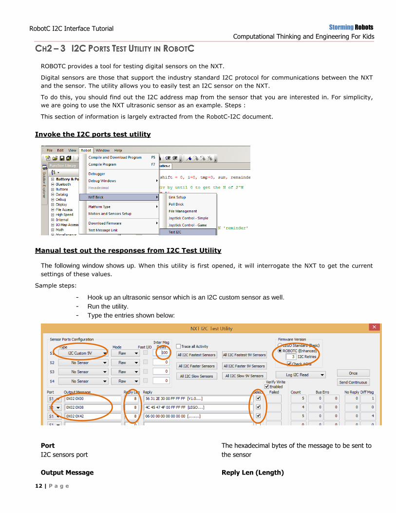
CH2 – 3 I2C PORTS TEST UTILITY IN ROBOTC
ROBOTC provides a tool for testing digital sensors on the NXT.
Digital sensors are those that support the industry standard I2C protocol for communications between the NXT
and the sensor. The utility allows you to easily test an I2C sensor on the NXT.
To do this, you should find out the I2C address map from the sensor that you are interested in. For simplicity,
we are going to use the NXT ultrasonic sensor as an example. Steps :
This section of information is largely extracted from the RobotC-I2C document.
Invoke the I2C ports test utility
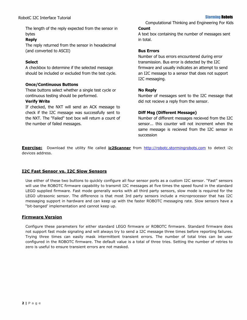
Manual test out the responses from I2C Test Utility
The following window shows up. When this utility is first opened, it will interrogate the NXT to get the current
settings of these values.
Sample steps:
- Hook up an ultrasonic sensor which is an I2C custom sensor as well.
- Run the utility.
- Type the entries shown below:
Port
I2C sensors port
Output Message
The hexadecimal bytes of the message to be sent to
the sensor
Reply Len (Length)
Storming Robots
Computational Thinking and Engineering For Kids
2 | P a g e
RobotC I2C Interface Tutorial
– Packet II
The length of the reply expected from the sensor in
bytes
Reply
The reply returned from the sensor in hexadecimal
(and converted to ASCII)
Select
A checkbox to determine if the selected message
should be included or excluded from the test cycle.
Once/Continuous Buttons
These buttons select whether a single test cycle or
continuous testing should be performed.
Verify Write
If checked, the NXT will send an ACK message to
check if the I2C message was successfully sent to
the NXT. The "Failed" text box will return a count of
the number of failed messages.
Count
A text box containing the number of messages sent
in total.
Bus Errors
Number of bus errors encountered during error
transmission. Bus error is detected by the I2C
firmware and usually indicates an attempt to send
an I2C message to a sensor that does not support
I2C messaging.
No Reply
Number of messages sent to the I2C message that
did not recieve a reply from the sensor.
Diff Msg (Different Message)
Number of different messages recieved from the I2C
sensor... this counter will not increment when the
same message is recieved from the I2C sensor in
succession
Exercise: Download the utility file called ic2Scanner from http://robotc.stormingrobots.com to detect i2c
devices address.
I2C Fast Sensor vs. I2C Slow Sensors
Use either of these two buttons to quickly configure all four sensor ports as a custom I2C sensor. “Fast” sensors
will use the ROBOTC firmware capability to transmit I2C messages at five times the speed found in the standard
LEGO supplied firmware. Fast mode generally works with all third party sensors, slow mode is required for the
LEGO ultrasonic sensor. The difference is that most 3rd party sensors include a microprocessor that has I2C
messaging support in hardware and can keep up with the faster ROBOTC messaging rate. Slow sensors have a
“bit-banged’ implementation and cannot keep up.
Firmware Version
Configure these parameters for either standard LEGO firmware or ROBOTC firmware. Standard firmware does
not support fast mode signaling and will always try to send a I2C message three times before reporting failures.
Trying three times can easily mask intermittent transient errors. The number of total tries can be user
configured in the ROBOTC firmware. The default value is a total of three tries. Setting the number of retries to
zero is useful to ensure transient errors are not masked.
Storming Robots
Computational Thinking and Engineering For Kids
12 | P a g e
RobotC I2C Interface Tutorial
– Packet II
CH2 – 4 WHAT IS I2C ADDRESS, MEMORY ADDRESS & BUS
Computers only understand binary. Any hardware must have way to store its data, i.e. memory address.
Memory Address (sometimes they may refer to as register) is a bit placeholder for bits information stored in
very fast memory/storage access area. This is built into the CPU (central processing unit) in order to speed up
its operations by providing quick access to commonly used values.
In short, it represents bits and bytes of data. True Registers are the top of the memory hierarchy and are the
fastest way for the system to manipulate data.
Typical uses of hardware registers include configuration and start-up of certain features, especially during
initialization, storage configuration for hardware devices, such as central processing unit, I/O devices like
sensors. etc.
Before you operate on the register data from a device, you need to know the “register layout”. In short, it is a
data map where you can get important data from the device like the tilt sensor.
e.g.
nDeviceAddress = 0x02;
nLocationPtr = 0x42;
IMPORTANT: This I2C memory address MUST be even … You will see why when you work with the I2C
code on the Arduino side.
In essence, I2C address is memory address. Distinction should be mentioned:
I2C address : an unique memory address to identify a specific I2C device. In the case when you connect to
multiple I2C devices, you must have an unique memory address to address each single device.
Other Memory addresses are used for certain commands determined by the manufacturer. If you are the one who
create the I2C device, you will be the one who create the I2C unique address, and all other command addresses.
A bus, as a computer term, may represent two things.
It can mean the physical electrical wires with multiples connections for hardware devices.
It can also mean any subsystem that provides the a specific set of functionality as an electrical bus.
The arrangement may use both parallel (multidrop) and bit-serial (daisy chain) connections. One example is
a USB hub.
In essence, a design of bus forms a standard interconnection points for which multiple manufacturers build
compatible and interchangeable interfaces.
Internal and external buses:
Internal buses all the internal components of a computer to the motherboard, e.g. CPU, math processor,
internal memory modules, etc. They are also called local bus. There are motherboard specific.
Memory Address Map
I2C Address vs other Memory Address Commands
Bus
Storming Robots
Computational Thinking and Engineering For Kids
13 | P a g e
RobotC I2C Interface Tutorial
– Packet II
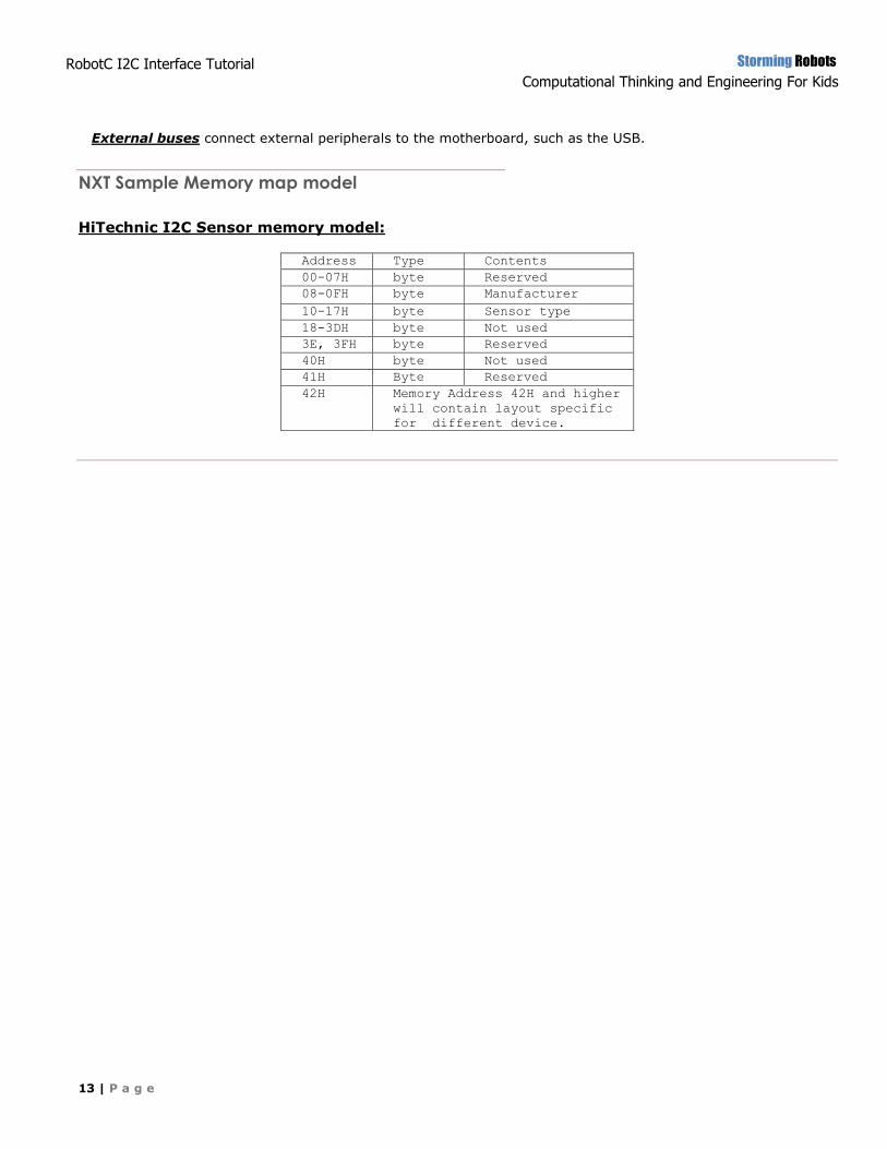
External buses connect external peripherals to the motherboard, such as the USB.
HiTechnic I2C Sensor memory model:
Address Type Contents
00-07H byte Reserved
08-0FH byte Manufacturer
10-17H byte Sensor type
18-3DH byte Not used
3E, 3FH byte Reserved
40H byte Not used
41H Byte Reserved
42H Memory Address 42H and higher
will contain layout specific
for different device.
NXT Sample Memory map model
Storming Robots
Computational Thinking and Engineering For Kids
14 | P a g e
RobotC I2C Interface Tutorial
– Packet II
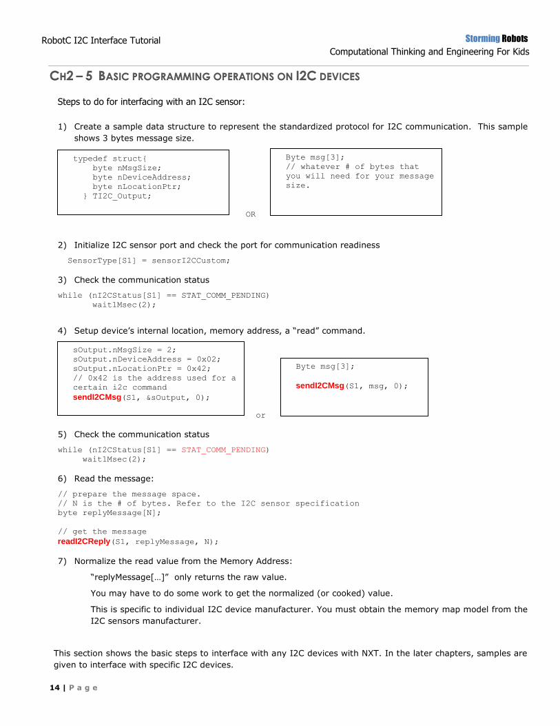
CH2 – 5 BASIC PROGRAMMING OPERATIONS ON I2C DEVICES
Steps to do for interfacing with an I2C sensor:
1) Create a sample data structure to represent the standardized protocol for I2C communication. This sample
shows 3 bytes message size.
OR
2) Initialize I2C sensor port and check the port for communication readiness
SensorType[S1] = sensorI2CCustom;
3) Check the communication status
while (nI2CStatus[S1] == STAT_COMM_PENDING)
wait1Msec(2);
4) Setup device’s internal location, memory address, a “read” command.
or
5) Check the communication status
while (nI2CStatus[S1] == STAT_COMM_PENDING)
wait1Msec(2);
6) Read the message:
// prepare the message space.
// N is the # of bytes. Refer to the I2C sensor specification
byte replyMessage[N];
// get the message
readI2CReply(S1, replyMessage, N);
7) Normalize the read value from the Memory Address:
“replyMessage[…]” only returns the raw value.
You may have to do some work to get the normalized (or cooked) value.
This is specific to individual I2C device manufacturer. You must obtain the memory map model from the
I2C sensors manufacturer.
This section shows the basic steps to interface with any I2C devices with NXT. In the later chapters, samples are
given to interface with specific I2C devices.
typedef struct{
byte nMsgSize;
byte nDeviceAddress;
byte nLocationPtr;
} TI2C_Output;
TI2C_Output sOutput;
Byte msg[3];
// whatever # of bytes that
you will need for your message
size.
sOutput.nMsgSize = 2;
sOutput.nDeviceAddress = 0x02;
sOutput.nLocationPtr = 0x42;
// 0x42 is the address used for a
certain i2c command
sendI2CMsg(S1, &sOutput, 0);
Byte msg[3];
sendI2CMsg(S1, msg, 0);
Storming Robots
Computational Thinking and Engineering For Kids
15 | P a g e
RobotC I2C Interface Tutorial
– Packet II
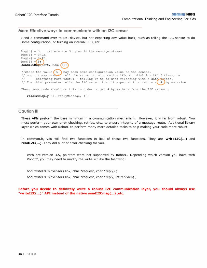
Send a command over to I2C device, but not expecting any value back, such as telling the I2C sensor to do
some configuration, or turning on internal LED, etc.
Msg[0] = 3; //there are 3 bytes in the message stream
Msg[1] = 0x02;
Msg[2] = 0x42;
Msg[3] = 5;
sendI2CMsg(port, Msg, 4);
//where the value 5 may mean some configuration value to the sensor.
// e.g. it may mean to tell the sensor turning on its LED, or blink its LED 5 times, or
// something more useful - telling it to do data filtering with 5 data points.
// The third parameter tells the I2C sensor that it expects it to return a 4 bytes value.
Then, your code should do this in order to get 4 bytes back from the I2C sensor :
readI2CReply(S1, replyMessage, 4);
These APIs preform the bare minimum in a communication mechanism. However, it is far from robust. You
must perform your own error checking, retries, etc., to ensure integrity of a message route. Additional library
layer which comes with RobotC to perform many more detailed tasks to help making your code more robust.
In common.h, you will find two functions in lieu of these two functions. They are writeI2C(…) and
readI2C(…). They did a lot of error checking for you.
With pre-version 3.5, pointers were not supported by RobotC. Depending which version you have with
RobotC, you may need to modify the writeI2C like the following:
bool writeI2C2(tSensors link, char *request, char *reply) ;
bool writeI2C2(tSensors link, char *request, char *reply, int replylen) ;
Before you decide to definitely write a robust I2C communication layer, you should always use
“writeI2C(…)” API instead of the native sendI2Cmsg(…) ,etc.
More Effective ways to communicate with an I2C sensor
Caution !!!
Storming Robots
Computational Thinking and Engineering For Kids
16 | P a g e
RobotC I2C Interface Tutorial
– Packet II
CH2 – 6 INTERFACE WITH NON-NXT I2C DEVICES
2 Big Gotcha-you points to watch out for:
Proprietary libraries
Pull-up resistors
NXT can interface with I2C devices which are not sensors. You should review the devices’ specification, and best
to at least get a logic analyzer to observe the device’s signaling behavior. More examples will be included here:
But in general, you are pretty much on your own!
<…Under construction …>
Storming Robots
Computational Thinking and Engineering For Kids
17 | P a g e
RobotC I2C Interface Tutorial
– Packet II
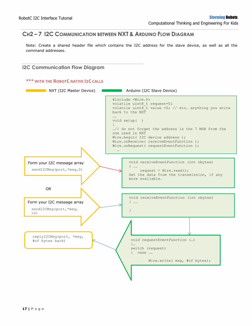
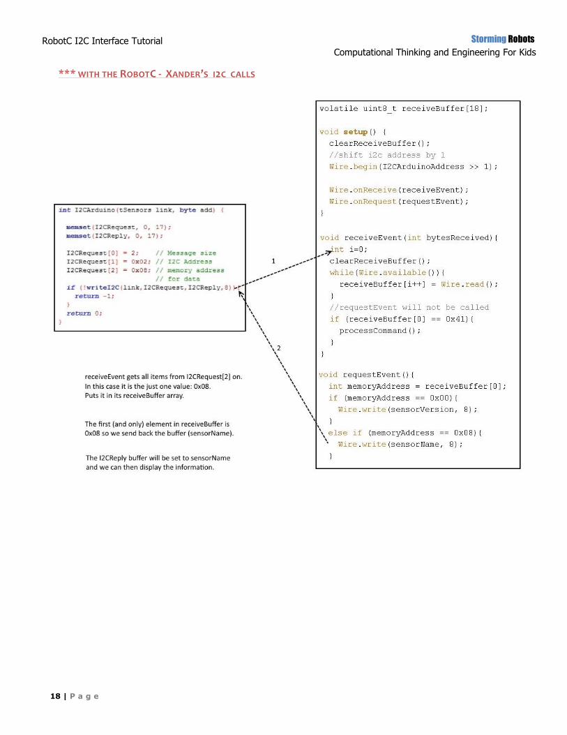
void receiveEventFunction (int nbytes)
{ ….
request = Wire.read();
Get the data from the transmission, if any
more available.
void receiveEventFunction (int nbytes)
{ ….
}
CH2 – 7 I2C COMMUNICATION BETWEEN NXT & ARDUINO FLOW DIAGRAM
Note: Create a shared header file which contains the I2C address for the slave device, as well as all the
command addresses.
*** WITH THE ROBOTC NATIVE I2C CALLS
NXT (I2C Master Device) Arduino (I2C Slave Device)
I2C Communication Flow Diagram
#include <Wire.h>
volatile uint8_t request=0l
volatile uint8_t value =0; // etc… anything you write
back to the NXT
….
void setup( )
{
…// do not forget the address is the 7 MSB from the
one used in NXT
Wire.begin( I2C device address );
Wire.onReceive( receiveEventFunction );
Wire.onRequest( requestEventFunction );
…
}
Form your I2C message array
sendI2CMsg(port,*msg,0)
void requestEventFunction (…)
{…
switch (request)
{ case ….
Wire.write( msg, #of bytes);
replyI2CMsg(port, *msg,
#of bytes back)
OR
Form your I2C message array
sendI2CMsg(port,*msg,
>0)
Storming Robots
Computational Thinking and Engineering For Kids
18 | P a g e
RobotC I2C Interface Tutorial
– Packet II
*** WITH THE ROBOTC - XANDER’S I2C CALLS
Storming Robots
Computational Thinking and Engineering For Kids
19 | P a g e
RobotC I2C Interface Tutorial
– Packet II
CH2 – 7 EXERCISES
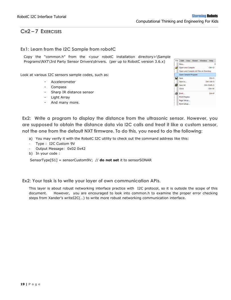
Ex1: Learn from the I2C Sample from robotC
Copy the “common.h” from the <your robotC installation directory>\Sample
Programs\NXT\3rd Party Sensor Drivers\drivers. (per up to RobotC version 3.6.x)
Look at various I2C sensors sample codes, such as:
- Accelerometer
- Compass
- Sharp IR distance sensor
- Light Array
- And many more.
Ex2: Write a program to display the distance from the ultrasonic sensor. However, you
are supposed to obtain the distance data via I2C calls and treat it like a custom sensor,
not the one from the default NXT firmware. To do this, you need to do the following:
a) You may verify it with the RobotC I2C utility to check out the command address like this:
- Type : I2C Custom 9V
- Output Message: 0x02 0x42
b) In your code :
SensorType[S1] = sensorCustom9V; // do not set it to sensorSONAR
Ex2: Your task is to write your layer of own communication APIs.
This layer is about robust networking interface practice with I2C protocol, so it is outside the scope of this
document. However, you are encouraged to look into common.h to examine the proper error checking
steps from Xander’s writeI2C(…) to write more robust networking communication interface.
Storming Robots
Computational Thinking and Engineering For Kids
20 | P a g e
RobotC I2C Interface Tutorial
– Packet II
CH3 – HITECHNIC ACCELEROMETER INTERFACE
Accelerometer is used to measure acceleration. It is used to measure a variety of things that are used in large
array of electronic equipment, and robots including Acceleration, Tilt angle, Vibration, or even Gravity.
Big thanks to MEMS, Micro-Electro-Mechanical-Systems under the category of NanoTechnology. It allows a
single accelerometer along with other transmitters all into a single substrate. While we are entering the
NanoTechnology era, accelerometers will permeate our lives as never before!
Applications:
Wii Game Controller, Car airbag deployment, any system which involves human motion monitoring and many
more.
Some educational videos:
o The Photolithography process used in M.E.M.S.
o Basic MEMS fabrication o Accelerometer measures RC car crash drop from 45ft. - Another Geek Moment
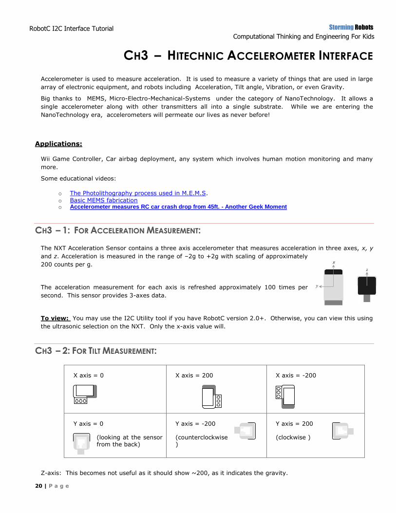
CH3 – 1: FOR ACCELERATION MEASUREMENT:
The NXT Acceleration Sensor contains a three axis accelerometer that measures acceleration in three axes, x, y
and z. Acceleration is measured in the range of –2g to +2g with scaling of approximately
200 counts per g.
The acceleration measurement for each axis is refreshed approximately 100 times per
second. This sensor provides 3-axes data.
To view: You may use the I2C Utility tool if you have RobotC version 2.0+. Otherwise, you can view this using
the ultrasonic selection on the NXT. Only the x-axis value will.
CH3 – 2: FOR TILT MEASUREMENT:
X axis = 0
X axis = 200
X axis = -200
Y axis = 0
(looking at the sensor from the back)
Y axis = -200
(counterclockwise )
Y axis = 200
(clockwise )
Z-axis: This becomes not useful as it should show ~200, as it indicates the gravity.
Storming Robots
Computational Thinking and Engineering For Kids
21 | P a g e
RobotC I2C Interface Tutorial
– Packet II
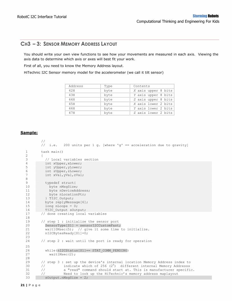
CH3 – 3: SENSOR MEMORY ADDRESS LAYOUT
You should write your own view functions to see how your movements are measured in each axis. Viewing the
axis data to determine which axis or axes will best fit your work.
First of all, you need to know the Memory Address layout.
HiTechnic I2C Sensor memory model for the accelerometer (we call it tilt sensor)
Address Type Contents
42H byte X axis upper 8 bits
43H byte Y axis upper 8 bits
44H byte Z axis upper 8 bits
45H byte X axis lower 2 bits
46H byte Y axis lower 2 bits
47H byte Z axis lower 2 bits
Sample:
//
// i.e. 200 units per 1 g. [where 'g' == acceleration due to gravity]
1 task main()
2 {
3 // Local variables section
4 int xUpper,xLower;
5 int yUpper,yLower;
6 int zUpper,zLower;
7 int xVal,yVal,zVal;
8
9 typedef struct{
10 byte nMsgSize;
11 byte nDeviceAddress;
12 byte nLocationPtr;
13 } TI2C_Output;
14 byte replyMessage[6];
15 long nLoops = 0;
16 TI2C_Output sOutput;
17 // done creating local variables
18
19 // step 1 : initialize the sensor port
20 SensorType[S1] = sensorI2CCustomFast;
21 wait10Msec(5); // give it some time to initialize.
22 nI2CBytesReady[S1]=0;
23
24 // step 2 : wait until the port is ready for operation
25 26 while(nI2CStatus[S1]== STAT_COMM_PENDING)
27 wait1Msec(2);
28
29 // step 3 : set up the device's internal location Memory Address index to
30 // indicate which of 256 (28) different internal Memory Addresss
31 // a "read" command should start at. This is manufacturer specific.
32 // Need to look up the HiTechnic’s memory address maplayout
33 sOutput.nMsgSize = 2;
Storming Robots
Computational Thinking and Engineering For Kids
22 | P a g e
RobotC I2C Interface Tutorial
– Packet II
34 sOutput.nDeviceAddress = 0x02;
35 sOutput.nLocationPtr = 0x42;
36
37 while(true)
38 { ++nLoops; // simple loop count for testing communication.
39 nI2CBytesReady[S1] = 0;
40
41 // step 4 : Send command to the sensor before read
42 sendI2CMsg(S1, sOutput, 6); // send 6 bytes of sOutput
43
44 while (nI2CStatus[S1] == STAT_COMM_PENDING)
45 wait1Msec(2);
46
47 memset(replyMessage, 0, 6);
48
49 if (nI2CStatus[S1] == NO_ERR)
50 {
51
52 // step 5 : read command to get 6 bytes of data and put them in replyMessage
53 readI2CReply(S1, replyMessage[0], 6);
54
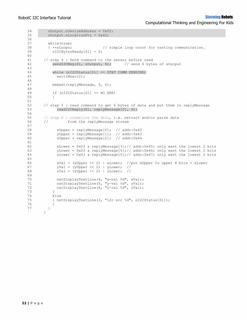
55 // step 6 : normalize the data, i.e. extract and/or parse data
56 // from the replyMessage stream
57
58 xUpper = replyMessage[0]; // addr:0x42
69 yUpper = replyMessage[1]; // addr:0x43
60 zUpper = replyMessage[2]; // addr:0x44
61
62 xLower = 0x03 & replyMessage[3];// addr:0x45; only want the lowest 2 bits
63 yLower = 0x03 & replyMessage[4];// addr:0x46; only want the lowest 2 bits
64 zLower = 0x03 & replyMessage[5];// addr:0x47; only want the lowest 2 bits
65
66 xVal = (xUpper << 2) | xLower; //put xUpper to upper 8 bits + xLower
67 yVal = (yUpper << 2) | yLower; //
68 zVal = (zUpper << 2) | zLower; //
69
70 nxtDisplayTextLine(4, "x-val %d", xVal);
71 nxtDisplayTextLine(5, "y-val %d", yVal);
72 nxtDisplayTextLine(6, "z-val %d", zVal);
73 }
74 Else
75 { nxtDisplayTextLine(3, "i2c err %d", nI2CStatus[S1]);
76 }
77 }
` }
Storming Robots
Computational Thinking and Engineering For Kids
23 | P a g e
RobotC I2C Interface Tutorial
– Packet II
CH4 – OTHER I2C DEVICE INTERFACE
Need the following 2 files from HiTechnic unless you will write your own I2C interfaces. They are at:
File > Open Sample Programs > 3rd Party Sensor Drivers >drivers
common.c, HTIRS2-driver.h
I2C InfraRed Seeker - version sample
HiTechnic has an excellent document about programming interface with Sensors Mux.
More will be added in the future.
HiTechnic InfraRed Seeker
HiTechnic Sensors Mux


![Getting Started in RobotC - RobotC for VEX Workshop · Getting Started in RobotC • // Comment • task • main() • motor[] • {} • wait1Msec() • ; • = • Header • Code](https://static.fdocuments.us/doc/165x107/5d5751e588c9934f278bdeaa/getting-started-in-robotc-robotc-for-vex-workshop-getting-started-in-robotc.jpg)