Robot technology
13
chapter 7 Industrial Robotics CHAPTER CONTENTS 7.1 Robot Anatomy and Related Attributes 7.1.1 Joints and Links 7.1.2 Common Robot Configurations 7.1.3 Joint Drive Systems 7.3 End Effectors 7.4 Sensors in Robotics 7.5 Industrial Robot Applications 7.5.1 Material Handling Applications 7.5.2 Processing Operations 7.5.3 Assembly and Inspection 7.6.1 leadthrough Programming 7.6.2 Robot Programming Languages 7.6.3 Simulation and Off-Line Programming 7.7 Engineering Analysis of Industrial Robots 7.1.1 Introduction to Manipulator Kinematics 7.7.2 Accuracy and Repeatability
-
Upload
niket-kawale -
Category
Education
-
view
1.972 -
download
1
Transcript of Robot technology
chapter 7
Industrial Robotics
CHAPTER CONTENTS
7.1 Robot Anatomy and Related Attributes7.1.1 Joints and Links7.1.2 Common Robot Configurations7.1.3 Joint Drive Systems
7.3 End Effectors
7.4 Sensors in Robotics7.5 Industrial Robot Applications
7.5.1 Material Handling Applications7.5.2 Processing Operations7.5.3 Assembly and Inspection
7.6.1 leadthrough Programming7.6.2 Robot Programming Languages7.6.3 Simulation and Off-Line Programming
7.7 Engineering Analysis of Industrial Robots
7.1.1 Introduction to Manipulator Kinematics7.7.2 Accuracy and Repeatability
Introduction
An industrial robot is a general-purpose, programmable machine possessing certain an-thropomorphic characteristics. The most obvious anthropomorphic characteristic of an in-dustrial robot is its mechanical ann, that is used to perform various industrial tasks. Otherhuman- like characteristics arc the robot's capability to respond to sensory inputs, corn-municate wi-h other machines, and make decisions. These capabilities permit robots toperform a variety of useful tasks. The development of robotics technology followed thedevelopment of nurnencat control (Historical Note 7.1),and the two technologies are quitesimilar. They both involve coordinated control of multiple axes (the axes are calledin robotics), and they both use dedicated digital computers as controllers. Whereas NC ma-chines arc designed to perform specific processes (e.g., machining, sheetmetal hole punch-ing, and thermal cutting), robots are designed for a wider variety of tasks. Typical productionapplications of industrial robots include spot welding, material transfer, machine loading,spray painting, and assembly.
Reasons for the commercial and technological importance of industrial robots in-clude the following:
• Robotscan be substituted for humans in hazardous or uncomfortable work environments.• A robot performs its work cycle with a consistency and repeatability that cannot be
attained by bumans.
• Robots can be reprogrammed. When the production run of the current task is com-pleted, a robot can be reprogrammed and equipped with the necessary tooling toperform an altogether different task.
• Robots are controlled by computers and can therefore be connected to other com-puter systems 10 achieve computer integrated manufacturing.
Historical Note 7.1
The word "robot" entered the English language through a Czechoslovakian play titledUniversal Robots. written by Karel Capek in the early 1920s.The Czech word "robota'' meansforced worker. In the English translation, the word was converted to "robot.t'The story line ofthe play centers around a scientist named Rossum who invents a chemical substance similar[()protoplasm and uses it to produce robots. The scientist's goal is for robots to serve humansand perform physicallabor, Rossum continues to make improvements in his invention, ulti-ruately pcrfectingit.These "perfect beings" begin to resent their subservient rolein society andturn against their masters, killing off allhuman life.
Rossum's invention was pure science fiction (at least in the 19205;howe vcr, advances inthe modern field of biotechnology may ultimately be capable of producing such robotic beings)au: short history must also include mention of two real inventors who made original contri-bullons to the technology of industrial robotics. The first was Cyril W Kenward, a British in-ventor who devised a rnampulator that moved on an x-y-z axis system. In 1954, Kenwardapplied for a British patent for his robotic device, and the patent was issued in I~57
The second inventor was an American named C. Devol is credited withtwo in~'entions related to robotics. The first was a device for magnetically recording electricalsignals so that the SIgnalscould be played back to control the operation of machinery. This de-VIcewas invented around 1946,and a U.S.patent was issued in 1952.Tbe second invention wasa robotic device. developed in the 1950s. that Devol called "Programmed Article. Transfer,"This device was intended for parts handling. The U.S. patent was finally issued in 1961.It wasa rough prot<Jtype for the hydmuJieally driven robots that were later built by Unimatiun, Inc

Chap. 7 I Industrial Robotics
Devol's proved ultimately to be far more important in the development and commercializa-tion of robotics technology, The reason for this was a catalyst in the person of loseph Engelberger. Engelberger had graduated with a degree in physics in 1949.As a student, he had readscience fiction novels about robots. By the mid-1950s. be was working for a company that made
control systems for jet engines. Hence. by the time a chance meeting occurred between En-
Connecticut. Devol described his programmed article transfer invention to Bngelberger. andthey subscqucr.tly began considering bow to develop the device as a commercial product forindustrvIn 1%2, Unimauon, Inc. was founded, with Engelberger as president. The name of thecompany's first product was a polar configuration robot. The first application of aUnimate robot was for unloading a die casting machine at a Ford Motor Company plant.
1ThlS quote was too good to resist. It was borrowed from Groover et al..lnduslrial RobotiCS: Technology,Programming,olldApp!tcoliolU[6]
7.1
The manipulator of an industrial robot is constructed of a series of joints and links. Robotanatomy is concerned with the types and sizes of these joints and links and other aspectsof the manipulator's physical construction.
Joints and Links
of an industrial robot is similar to a joint in the human body: It provides relativemotion between two parts of the body. Each joint, or as it is sometimes called, providesthe robot with a so-called degree-of-freedom (d.of.) of motion. In nearly all cases, only onedegree-of-freedom is associated with a joint. Robots are often classified according to thetotal number of degrees-of-freedom they possess. Connected to each joint are two links, aninput link and an output link. Links are the rigid components of the rabat manipulator. ThepurJXlse of the joint is to provide controlled relative movement between the input link andthe output link.
Most robots are mounted on a stationary base on the floor. Let us refer to that baseand its connection to the first joint as link 0.1t is the input link to joint 1, the first in the se-ries of joints used in the construction of the robot. The output link of joint 1 is link 1. Link1 is the input link to joint 2, whose output link is link 2, and so forth. This joint-link num-bering scheme is illustrated in Figure 7.1.
Nearly all industrial robots have mechanical joints that can be classified into one offive types: two types that provide translational motion and three types that provide rotarymotion. These joint types are illustrated in Figure 7.2 and are based on a scheme describedin [6]. The five joint types are:
(a) Linearjoint(type Ljoint).The relative movement between the input link and the out-put link is a translational sliding motion, with the axes of the two links being parallel.
(b) JOint (type U joint). This is also a translational sliding motion, but theinput and output links are perpendicular to each other during the move.

Sec. 7.1 Robot Anatomy and Related Attributes
1omt2
Figure 7.1 Diagram of robot construction showing how a robot ismade up of a series of joint-link combinations.
(a) Joint
n
J~n
(oj
Input link Output link
Five types of joints commonly used in industrial robotconstruction: (a) linear joint (type L joint), (b) orthogonal joint (typeo joint), (c) rotational joint (type Rjoint),(d) twisting joint (typeTjoint), and (e) revolving joint (type V joint).
Eilckl['arm~l..ink 1
)UnlO
Joint;1
jOutpUllink
Input link
Output link
\lointmotion
Input link
214
(c) Rotational Joml (type joint). This type provides rotational relative motion, with
(d) 'twisting joint (type T jointj.T'his joint also involves rotary motion,but the axis or ro-tation is parallel to the axes of the two links.
(e) Revolvmg joint (type joint, from the "v' in revolving). In this joint type, the axisthe input link is parallel to the axis of rotation of the joint. and the axis of the
put link perpendicular to the axis of rotation.
Each of these joint types has a range over which it can be moved. The range for a transla-tional joint is usually less than a meter. The three types of rotary joints may have a rangeas small as a few degrees or as large as several complete turns
Common Robot Configurations
A rohot manipulator can he divided into two sections: a body-and-arm assembly and aassembly. There are usually three degrees-of-freedom associated with the body-and-
arm, and either two or three degrees-of-freedom associated with the wrist. At the end ot themanipulator's wrist is a device related to the task that must be accomplished by the robot.The device, called an end effector (Section 7.3), is usually either (1) a gripper for holding awurkpan or (2) a TOolfor performing some process. The body-and-arm ortne rotor is usedto position the end effector. and the robot's wrist is used to orient the end effector.
Body-and· Arm Configurations. Given the five types of joints defined above, thereare 5 :x 5 x 5 "" 125 different combinations of joints that can be used to design the body-and-arm assembly for a three-degree-of-freedom robot manipulator. In addition, there aredesign variations within the individual joint types [e.g.. physical size of the joint and rangeof motion). It is somewhat remarkable, therefore, that there are only five basic configura-tions commonly available in commercial industrial robots. These five configurations are:
1 Polar configuration. This configuration (Figure 7.3) consists of a sliding arm (L joint)actuated relative to the body, that can rotate about both a vertical axis (1' joint) anda horizontal axis (Rjoint).
This robot configuration (Figure 7.4) consists of a verticalcolumn, relative to which an arm assembly is moved up or down. The arm can bemoved in and out relative to the axis of the column. Our figure shows one possibleway in which this configuration can be constructed, using a T joint to rotate the col-umn about its axis An 1. joint is used to move the arm assembly vertically along thecolumn, while an 0 joint is used to achieve radial movement of the ann,
3. Cartesian coordinate robot. Other names for this configuration include rectilinearrobot and robot. As shown in Figure 7 5,it is composed of three sliding joints,two of which are orthogonal.
4, Jointed-arm robot. This robot manipulator (Figure 7.6) has the general configurationof a human arm. The jointed arm consists of a vertical column that swivels about the
'I: ,hould be noted thaI Ibere are possible variations in the Join types thai can be used to construct the
2

Sec.7.1 I Robot Anatomy and Related Attributes 215
7.3 Polar coordinate body-and-armassembly.
Cylindrical body-and-ann assembly.
~T~-
7.5 Cartesian coordinate body-and-armassembly.
Jointed-ann body-and-ann assembly.
base using a T joint.At the top of the column is a shoulder joint (shown as anin our figure), whose output link connects to an elbow joint (another R joint)
5. SCARA. SCARA is an acronym for Selective Compliance Assembly Robot Arm.This configuration (Figure 7.7) is similar to the jointed arm robot except that theshoulder and elbow rotational axes are vertical, which means that the arm is veryrigid in the vertical direction. but compliant in the horizontal direction. This permitsIhe robot to perform insertion tasks (for assembly) in a vertical direction, where someside-to-vide alignment may be needed to mate the two parts properly.

Figure 7,7 SCARA bodv-and-arrnassembly. .
Figure 7.8 Typical configuration of a three-degree-of-freedom wrist assembly showing roll, pitch, and yaw.
The robot's wrist is used to establish the orientation of theend effector. Robot wrists usually consist of two or three degrees-of-freedom. Figure 7.8illustrates one possible configuration for a three-degree-of-freedom wrist assembly. Thethree joints are defined as: (1) using a Tjoint to accomplish rotation about the robot'sarm axrs: (2) which involves up-and-down rotation, typically using a R joint; and
yaw, which involves right-and-left rotation, also accomplished by means of anA two-d.o.f wrist typically includes only roll and pitch joints (T and R joints).
To avoid confusion in the pitch and yaw definitions, the wrist roll should be assumedin its center position, as shown in our figure. To demonstrate the possible confusion, con-sider a two-jointed wrist assembly. With the roll joint in its center position, the second joint(Rjoint) provides up-and-down rotation (pitch). However, if the roll position were 90 de-grees from center (either clockwise or counterclockwise), the second joint would providea right-left rotation (yaw).
The SCARA robot configuration (Figure 7.7) is unique in that it typically does nothave a separate wrist assembly. As indicated in our description, it is used for insertion typeassembly operations in that the insertion is made from above. Accordingly. the orientationrequirements are minimal,and the wrist is therefore not needed. Orientation of the objectto be inserted is sometimes required, and an additional rotary joint can be provided for thispurpose. The other four body-and-ann configurations possess wrist assemblies that almostalways consist of combinations of rotary joints of types Rand T.
The letter symbols for the five joint types (L, 0, R, T, andV) can be used to define a joint notation system for the robot manipulator.ln this notationsystem, the manipulator is described by the joint types that make up the body-and-ann as-sembly. followed by the joint symbols that make lip the wrist. For example, the notationTLR: TR represents a five degree-of-freedom manipulator whose body-and-arm is madeup of a twisting joint (joint 1 T),a linear joint (joint 2 L), and a rotational joint (joint3 R). The wrist consists of two joints, a twisting joint (joint 4 T) and a rotational joint(joint 5 '" R). A colon separates the body-and-arm notation from the wrist notation.Typical joint notations for the five common body-and-arm configurations are presented inTable 7.1 . Common wrist joint notations are TRR and TR.
Attachedrobot

217
TABLE
Boov-ena-ArmAlternative
armSCARA
7.3l
LOO (Fiqure 7.517.6)
LVL
Work Volume. The work volume (the term work envelope is also used) of the ma-nipulator is defined as the envelope or space within which the robot can manipulate the endof its wrist. Work volume is determined by the number and types of joints in the manipu-lator (body-and-arm and wrist), the ranges of the various joints, and the physical sizes ofthe links. The shape of the work volume depends largely on the robot's configuration. Apolar configuration robot tends to have a partial sphere as its work volume, a cylindricalrobot has a cylindrical work envelope.and a Cartesian coordinate robot rectangularwork volume.
Joint Orive Systems
Robot joints are actuated using any of three possible types of drive systems: (1) electric,(2) hydraulic, or (3) pneumatic. Electric drive systems use electric motors as joint actuators(e.g., servomotors or stepping motors, the same types of motors used in NC positioningsystems,Chapter 6), Hydraulic and pneumatic drive systems use devices such as linear pis-tons and rotary vane actuators to accomplish the motion of the joint.
Pneumatic drive is typically limited to smaller robots used in simple material trans-fer applications. Electric drive and hydraulic drive are used on more-sophisticated indus-trial robot>. Electric drive has become the preferred drive system in commercially availablerobots, as electric motor technology has advanced in recent years. It is rnore readily adapt-able to computer control, which is the dominant technology used today for robot con-trollers. Electric drive robots are relatively accurate compared with hydraulically poweredrobots. By contrast, the advantages of hydraulic drive include greater speed and strength.
The drive system, position sensors (and speed sensors if used), and feedback controlsystems for the joints determine the dynamic response characteristics of the manipulator.The speed with which the robot can achieve a programmed position and the stability of itsmotion are important characteristics of dynamic response in robotics. Speed refers to theabsolute velocity of the manipulator at its end-of-arm. The maximum speed of a large robotis around 2 rn/sec (6 ft/sec). Speed call be programmed into the work cycle so that differ-ent portions of the cycle are carried out at different velocities. What is sometimes moreimportant than speed is the robot's capability to accelerate and decelerate in a controlledmanner. In many work cycles. much of the robot's movement is performed in a confinedregion of the work volume; hence, the robot never achieves it~ top-rated velocity. In thesecases, nearly all of the motion cycle is engaged in acceleration and deceleration rather thanin constant speed. Other factors that influence speed of motion are the weight (mass) ofthe object that is being manipulated and the precision with which the object must be located

218
at the end of a given move.A term that takes au of these factors into consideration is speedof response, thar refers to the time required the manipulator 10 move from one pointin space to the next. Speed of response is important because influences the robot's cycletime, that in turn affects the production rute in the application. Stability refers to the amountof overshoot and oscillation that occurs in the robot motion at the end-or-arm as at-
dication of less stability. The problem is that robots with greater stability are inherentlyslower in their response, whereas faster robots are generally less stable.
Load carrying capacity depends on the robot's physical size and construction as wellas the force and power that can be transmitted to the end of the wrist. The weight carry-ing capacity of commercial robots ranges from less than 1 kg up to approximately 900 kg(2000 lb). Medium sized robots designed for typical industrial applications have capacitiesin the range 10 to 45 kg (25 to 100 Ib). One factor that should be kept in mind when con-sidering load carrying capacity is that a robot usually works with a tool or gripper attachedto its wrist Grippers are designed to grasp and move objects about the work cell. The netload carrying capacity of the robot is obviously reduced by the weight of the gripper. Ifthe robot is rated at a 10 kg (22 lb} capacity and the weight of the gripper is 4 kg (9 lbs},then the net weight carrying capacity is reduced to 6 kg (13Ib)
7.2 ROBOT CONTROL SYSTEMS
The actuations of the individual joints must be controlled in a coordinated fashion for themanipulator to perform a desired motion cycle. Microprocessor-based controllers are com-monly used today in robotics as the control system hardware. The controller is organizedin a hierarchical structure as indicated in Figure 7.9 so that each joint has its own feedbackcontrol system, and a supervisory controller coordinates the combined actuations of thejoints according to the sequence of the robot program. Different types of control are re-quired for different applications. Robot controllers can be classified into four categories [6]:(1) limited sequence control, (2) playhack with point-to-point control, (3) playback with coo-tinuous path control, and (4) intelligent control.
This is the most elementary control type. It can beutilized only for simple motion cycles, such as pick-and-place operations [i.e., picking an ob-ject up at one location and placing it at another location). It is usually implemented by set-ting limits or mechanical stops for each joint and sequencing the actuation of the joints to
7.9 Hierarchical control structure of a robot microcomput-ercontroller.
Executiveproces>or
Computationsprocessor

Sec. 7.2 Robot Control Systems
has so that the next step in the sequence can beHowever. there is no servo-control to accomplish precise positioning of the joint. Manypneumatically driven robots are limited sequence robots.
Playback robots represent a marc-sophis-ticated form of control than limited sequence robots. Playback control means that the con-troller has a memory to record the sequence of motions in a given work cycle as well as thelocations and other parameters (such as speed) associated with each motion and then to sun-sequently play back the work cycle during execution of the program. It is this playbackfeature that give~ the control type its name. Tnpoint-to-point (PTP) control, individual po-sitions of the robot arm are recorded into memory. These positions are notlimited to me-chanical stops for each joint as in limited sequence robots. Instead. each position in therobot program consists of a set of values reprcsenung locations in the range of each jointof the manipulator. For each position defined the program, the joints arc thus directedto actuate to their respective specified locations. Feedback control is used during the mo-tion cycle to confirm that the individual joints achieve the specified locations in the program
Continuous puth robots have the sameplayback capability as the previous type. The difference between continuous path andpoint-to-point is the same in robotics as it is in NC (Section 6.1.3). A playback robot withcontinuous path control is capable of one or both of the following:
1 Cremer storage capacity. The controller has a far greater storage capacity than itspoint-to-point counterpart, so that the number of locations that can be recorded intomemory is far greater than for point-to-point. Thus, the points constituting the mo-tion cycle can be spaced very closely together to permit the robot to accomplish asmooth continuous motion. In PTP. only the final location of the individual motionelements arc controlled. so the path taken by the arm to reach the final location is notcontrolled. In a continuous path motion, the movement of the arm and wnsr is con-trolled during the motion.
rhe cotJlro!JercolJlpules the path between the starting pointand the ending point of each move using interpolation routines similar to those usedin NC These routines generally include linear and circular interpolation (Table 6.1).
The difference between and continuous path control can be distinguished in the fol-lowing mathematical way. Consider a three-axis Cartesian coordinate manipulator in thatthe end-of-arm is moved in x-y-z spareIn point-to-point systems, the .r, y, and z axes arecontrolled to achieve a specified point location within the robot's work volume. contin-uous path systems. not only are the .r, Land z axes controlled. but the velocities dx/dt.dy/dt.and dzldl are controlled simultaneously to achieve the specified linear or curvilinearpath. Servo-control is used to continuously regulate the position and speed of the manip-ulator. It should be mentioned that a playback robot with continuous path control has thecapacity for PTP control.
Control. Industrial robots are becoming increasingly intelligeru.In thiscontext. an intelligent robot is one that exhibits behavior that makes it seem intelligent.Some of the characteristics that make a robot appear intelligent include the capacity to:
220 Chap.7/ Industrial Robotics
• interact its environment• make decisions when things go wrong during the work cycle• communicate with humans• make computations during the motion cycle
In addition, robots with intelligent control possess playback capability for both PTP orcontinuous path control. These features require (1) a relatively high level of computer con-trol and (2) an advanced programming language to input the decision-making logic and
In our discussion of robot configurations (Section 7.1.2), we mentioned that an endeffec-tor is usually attached to the robot's wrist. The end effector enables the robot to accom-plish a specific task. Because of the wide variety of tasks performed by industrial robots,the end effector must usually be custom-engineered and fabricated for each different ap-plication. The two categories of end effectors are grippers and tools.
Grippers are end effectors used to grasp and manipulate objects during the work cycle.The objects are usually workparts that are moved from one location to another in the cell.Machine loading and unloading applications fall into this category (Section 7.5.1). Owingto the variety of part shapes, sizes, and weights, grippers must usually be custom designed.Types of grippers used in industrial robot applications include the following:
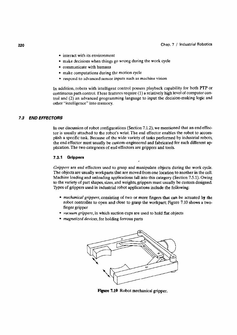
• mechanical grippers, consisting of two or more fingers that can be actuated therobot controller to open and dose to grasp the workpart; Figure 7.10 shows a two-finger gripper
• vacuum grippers, in which suction cups are used to hold flat objects• magnetized devices, for holding ferrous parts
Figure 7.10 Robot mechanical gripper.
Sec, 7.3 I End Effectors
• adhesive devices, where an adhesive substance is used to hold a flexible material such
• simple mechanical devices such as hooks and scoops.
Mechanical grippers are the most common gripper type. Some of the innovationsund advances in mechanical gripper technology include:
• Dual grippers, consisting of two gripper devices in one end effector, which are usefulfor machine loading and unloading. With a single gripper, the robot must reach intothe production machine twice. once to unload the finished part from the machine,and the second time to load the next part into the machine. With a dual gripper, therobot picks up the next workpart while the machine is still processing the precedingpart: when the machine finishes, the robot reaches into the machine once to removethe finished part and load the next part. This reduces the cycle time per part.
• interchangeable fingers that can be used on one gripper mechanism. To accommo-date different parts, different fingers are attached to the gripper.
• Sensory feedback in the fingers that provide the gripper with capabilities such as:(1) sensing the presence of the workpart or (2) applying a specified limited force tothe workpart during gripping (for fragile workparts).
• Multiple fingered grippers that possess the general anatomy of a human hand.• Standard gripper products that are commercially available, thus reducing the need to
custom-design a gripper for each separate robot application.
Tools are used in applications where the robot must perform some processing operationon the workpart. The robot therefore manipulates the tool relative to a stationary or slow-ly moving object (e.g., work part or subassembly). Examples of the tools used as end ef-fectors by robots to perform processing applications include:
• spot welding gun• arc welding tool• spray painting gun• rotating spindle for drilling, routing. grinding, and so forth• assembly tool (e.g., automatic screwdriver)• heating torch• water jet cutting tool.
In each case, the robot must not only control the relative position of the tool with respectto the work as a function of time, it must also control the operation of the tool. For this pur-pose. the robot must be able to transmit control signals to the tool for starting, stopping,and otherwise regulating its actions.
In some applications, multiple tools must be used by the robot during the work cycle,For example. several sizes of routing or drilling bits must be applied to the workpart. Thus,a means of rapidly changing the tools must be provided. The end effector in this case takesthe form of a fast-change tool holder for quickly fastenmg and unfastening the varioustools used during the work cycle.
222 Chap. 7 I Industrial Robotics
7.4
The general topic of sensors as components in control systems is discussed in Chapter 5(Section 5.1). Here we discuss sensors as they are applied in robotics. Sensors used in in-dustrial robotics can be classified into two categories: (1) internal and (2) external. Inter-
robot. These sensors form a feedback control loop with the robot controller. Typical sen-sors used to control the position of the robot arm include potentiometers and optical en-coders. To control the speed of the robot arm, tachometers of various types are used.
External sensors are used to coordinate the operation of the robot with other equip-ment in the cell. In many cases, these external sensors are relatively simple devices.such aslimit switches that determine whether a part has been positioned properly in a fixture orthat indicate that a part is ready to be picked up at a conveyor. Other situations requiremore-advanced sensor technologies, including the following:
• Tactile sensors. Used to determine whether contact is made between the sensor andanother object. Tactile sensors can be divided into two types in robot applications:(1) touch sensors and (2) force sensors, Touch sensors are those that indicate simplythat contact has been made with the object. Force sensors are used to indicate themagnitude of the force with the object. This might be useful in a gripper to measureand control the force being applied to grasp an object.
• Proximity sensors. Indicate when an object is close to the sensor, When this type ofsensor is used to indicate the actual distance of the object, it is called a range sensor.
• Optical sen.wn· .Photocells and other photometric devices can be utilized to detect thepresence or absence of objects and are often used for proximity detection.
• Machine vision. Used in robotics for inspection, parts identification, guidance, andother uses. In Section 23.6, we provide a more-complete discussion of machine vi-sion in automated inspection.
• Other sensors. This miscellaneous category includes other types of sensors that mightbe used in robotics, including devices for measuring temperature, fluid pressure, fluidflow, electrical voltage, current, and various other physical properties.
7.5 INDUSTRIAL ROBOT APPLlCAnONS
One of the earliest installations of an industrial robot was around 1961 in a die caeting op-eration [51.The robot was used to unload castings from the die casting machine. The typ-ical environment in die casting is not pleasant for humans due to the heat and fumes emittedby the casting process. It seemed quite logical to use a robot in this type of work environ-ment in place of a human operator. Work environment is one of several characteristics thatshould be considered when selecting a robot application. The general characteristics orin-dustrial work situations that tend to promote the substitution of robots for human laborare the following:
1. Hazardous work environment for humans. When the work environment is unsafe,unhealthful, hazardous, uncomfortable, or otherwise unpleasant for humans, there isreason to consider an industrial robot for the work. In addition to die casting, thereare many other work situations that are hazardous or unpleasant for humans, in-