Robo 3.1 An Autonomous Wall Following Robot · Robo 3.1 An Autonomous Wall Following Robot Samarth...
34
Robo 3.1 An Autonomous Wall Following Robot Samarth Mehta * Department of Electrical and Computer Engineering Cleveland State University Cleveland, Ohio 44115 May 1, 2008 * Email address: [email protected] . This work was primarily supported by Provost of Cleveland State University through Honors Department under the program called REU (Research Experience for Undergraduates) in Summer 2007.
Transcript of Robo 3.1 An Autonomous Wall Following Robot · Robo 3.1 An Autonomous Wall Following Robot Samarth...
Robo 3.1 An Autonomous Wall Following Robot
Samarth Mehta* Department of Electrical and Computer Engineering
Cleveland State University Cleveland, Ohio 44115
May 1, 2008
* Email address: [email protected]. This work was primarily supported by Provost of Cleveland State University through Honors Department under the program called REU (Research Experience for Undergraduates) in Summer 2007.
Robo 3.1 An Autonomous Wall Following Robot Samarth Mehta
Page 1 of 34
Abstract This report presents a wall following autonomous mobile robot—Robo 3.1. It follows a wall on its left. Robo 3.1 used a PIC 18F4520 microcontroller as its brain. PIC 18F4520 receives input from Ultrasonic Distance Meter (UDM). Some computations are performed on this input and a control signal is generated to control the robot’s position. This control signal is generated through a PD controller, which is implemented in the microcontroller. First, simulations were performed in Matlab to design a PD controller and to understand the overall picture of the robot’s behavior. Afterwards, microcontroller was programmed in C language using a CCS compiler. The robot was fine tuned during the tests. The test results are illustrated. 1. Introduction Autonomous robots are electromechanical devices that are programmed to achieve several goals. They are involved in a few tasks such as moving and lifting objects, gathering information related to temperature and humidity, and follow walls. From a system’s engineering point of view, a well designed autonomous robot has to be adaptable enough to control its actions. In addition, it needs to perform desired tasks precisely and accurately. The overall objective of this project is to follow a wall on its left and maintain a constant distance with it. (Left sides and right sides are considered from robot’s point of view unless it is specified.) In general, the robotic chassis are designed carefully, so that they are balanced. After loading this chassis with the battery packs and other electronics, the chassis become unbalanced. In addition, the plane on which the robot is moving could also be uneven. These result in a veering of the robot. This may cause the robot either to run into a wall, or go farther away form the wall. Therefore, a decent control technique is required to tackle this problem. In summer 2007, a team of six undergraduate students developed a project—Robotic Swarms [8]—under the supervision of a graduate student and an associate professor at Cleveland State University. One of the tasks of this project was to implement a wall following capability in to the robots. A closed loop control technique was used to follow a wall that had large response time to reach to the set value. Therefore, there was a need to develop a system that can improve the response time.
1.1. Literature Search In order to follow a wall and navigate through small pathways, image processing techniques can be used. This technique requires cameras that can be expensive. Reference [9] suggests using two switches on the left of the robot to follow left wall and a bumper switch to detect an obstruction in front. A genetic algorithm using Fuzzy Logic Controller is developed in [7]. A multivariable control and ultrasonic range finders for the measurement of a distance are being used for wall tracking robot in [2]. A Fuzzy Logic Controller is used to drive a robot parallel to the wall with the help of ultrasonic sensors in [13].
Robo 3.1 An Autonomous Wall Following Robot Samarth Mehta
Page 2 of 34
1.2. Summary of Sections Section 2 discusses the choice of controller and mathematical model along with the simulations in Matlab. Section 3 explains hardware and software for motors, Ultrasonic Distance Meter and PD Controller in detail. Section 5 gives the conclusion based on the observations and results. 2. Controller, Mathematical Model and Simulations
2.1. Controller There are several techniques that can be used to control mobile robots. One of the techniques is an open loop control. In the open loop control system of a robot, the inputs such as speed, distance, a path between the start and end points are calculated beforehand. This technique does not handle disturbances or correct one of the parameters that could go wrong. Other technique that can be used is a closed loop control. The closed loop control system can compensate for the errors occur in real time since the inputs are based on the actual conditions and not predefined by the assumptions. In order to have accurate and precise controlled actions of a robot a closed loop system is preferred over an open loop system. There are various types of controllers that can be used in a closed loop control system. The basic controllers that are used widely are Proportional (P) controller, Proportional Integral (PI) controller, Proportional Derivative (PD) controller, and Proportional Integral Derivative (PID) controller. For a wall following robot, PD controller turns out to be a fairly decent controller, which will be discussed in Section 2.3 while discussing simulations of PD controller.
2.2. Mathematical Model Different designs such as legged or wheeled robots have different mathematical models. Furthermore, wheeled robots have several types such as synchronous drive, Omni directional and differential drive [3]. The differential drive method is simple to implement and sharp turns can be made. Therefore, differential drive technique is used for this project. The differential drive robots with wall following robots have a number of applications. For example: building a map of an unknown area, manufacturing, rescue services and various military applications, and collecting data and monitoring various parameters such as temperature and humidity. In general, robot is a non-linear system that can be understood from the following equations [2].
θcos2
rl vvx
+=
•
(1)
Robo 3.1 An Autonomous Wall Following Robot Samarth Mehta
Page 3 of 34
Lvv lr +=
•
θ (2)
θsin2
rl vvy
+=
•
(3),
The following list gives the meaning of the symbols used in the above equations.
lv = left wheel linear velocity
rv = right wheel linear velocity L = distance between two wheels x = horizontal distance •
x = rate of change in horizontal position y = vertical distance •
y = rate of change in vertical position θ = angular position of a robot with respect to x •
θ = rate of change in angular position One can see from the above equations, that the robot has a non-linear system because of cosine and sine terms. In this project, robot needs to maintain a constant distance from a wall, which is a horizontal distance. In this project, a wall following robot does not need to control vertical position. Therefore, there is no need to use (3).
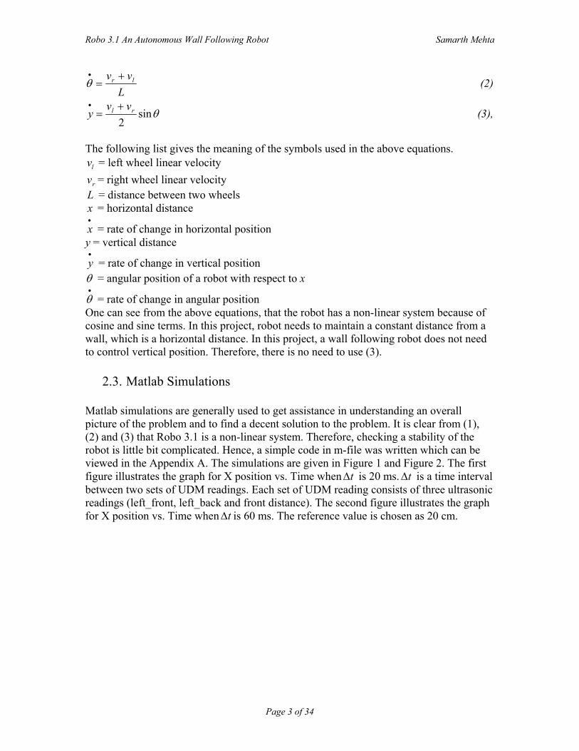
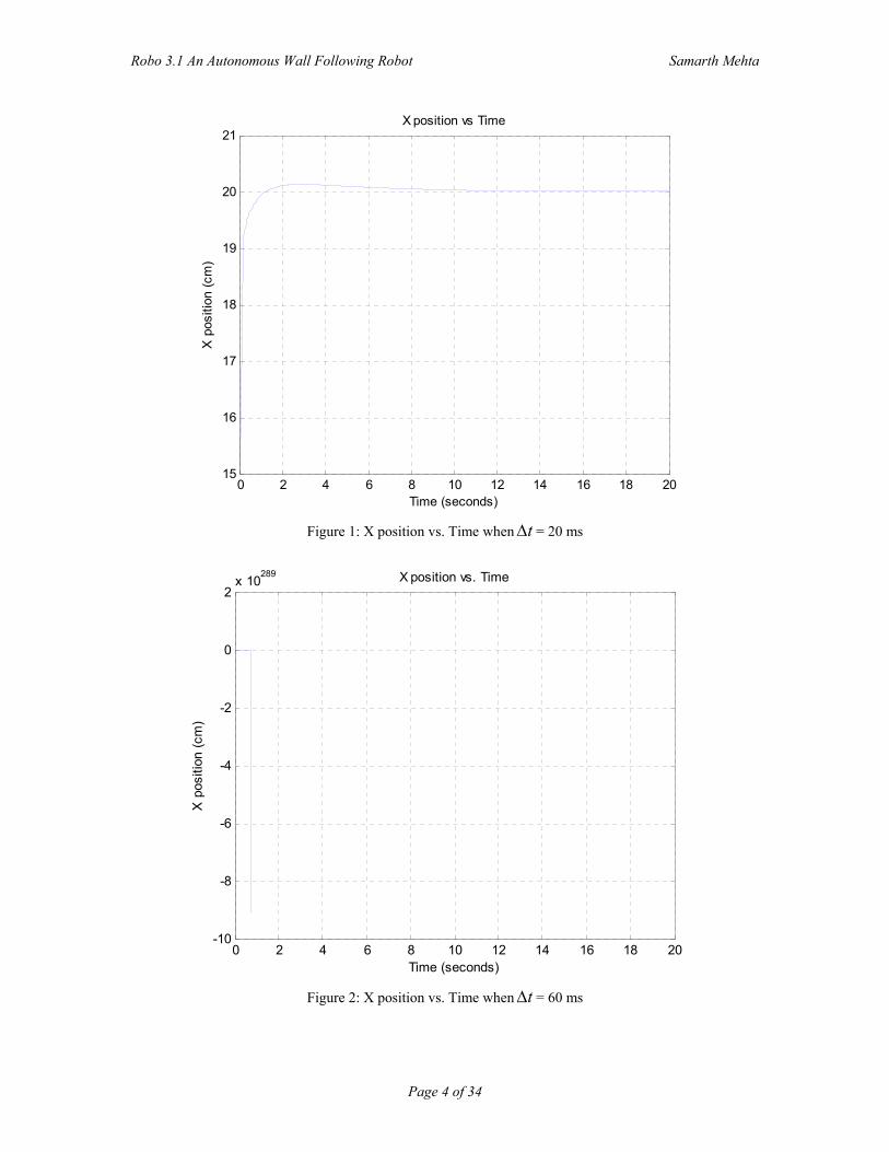
2.3. Matlab Simulations Matlab simulations are generally used to get assistance in understanding an overall picture of the problem and to find a decent solution to the problem. It is clear from (1), (2) and (3) that Robo 3.1 is a non-linear system. Therefore, checking a stability of the robot is little bit complicated. Hence, a simple code in m-file was written which can be viewed in the Appendix A. The simulations are given in Figure 1 and Figure 2. The first figure illustrates the graph for X position vs. Time when t∆ is 20 ms. t∆ is a time interval between two sets of UDM readings. Each set of UDM reading consists of three ultrasonic readings (left_front, left_back and front distance). The second figure illustrates the graph for X position vs. Time when t∆ is 60 ms. The reference value is chosen as 20 cm.
Robo 3.1 An Autonomous Wall Following Robot Samarth Mehta
Page 4 of 34
0 2 4 6 8 10 12 14 16 18 2015
16
17
18
19
20
21
Time (seconds)
X p
ositi
on (c
m)
X position vs Time
Figure 1: X position vs. Time when t∆ = 20 ms
0 2 4 6 8 10 12 14 16 18 20-10
-8
-6
-4
-2
0
2x 10
289
Time (seconds)
X p
ositi
on (c
m)
X position vs. Time
Figure 2: X position vs. Time when t∆ = 60 ms
Robo 3.1 An Autonomous Wall Following Robot Samarth Mehta
Page 5 of 34
Figure 1 proves that gains chosen for PD controller for t∆ = 20 ms are correct. On the other hand, same gains are improper when t∆ = 60 ms as shown in Figure 2. Ultrasonic Distance Meter may take approximately 450 µs to 60 ms. Even if ultrasonic readings are taken continuously without waiting for 10 to 100 µs, t∆ will be about 60 ms in worst case. Tuning a controller based on such wide variations is very difficult. However, it can be concluded from first figure that if t∆ is quite small and if it does not vary with large amount than PD controller can perform appropriately. 3. Hardware and Software
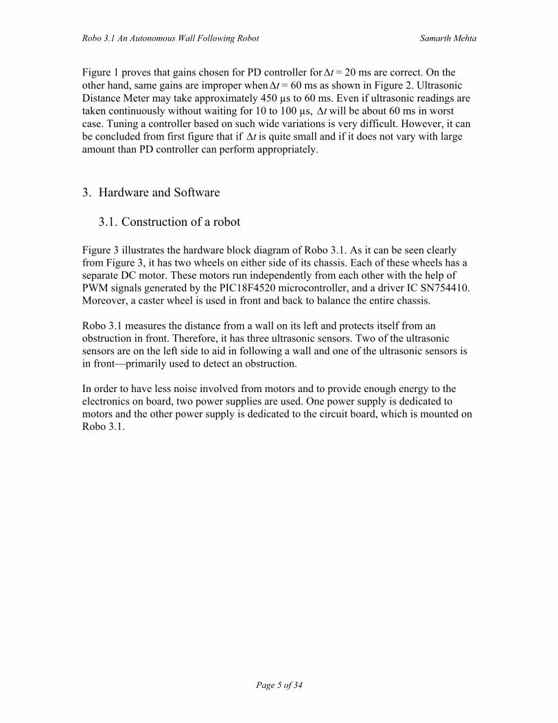
3.1. Construction of a robot Figure 3 illustrates the hardware block diagram of Robo 3.1. As it can be seen clearly from Figure 3, it has two wheels on either side of its chassis. Each of these wheels has a separate DC motor. These motors run independently from each other with the help of PWM signals generated by the PIC18F4520 microcontroller, and a driver IC SN754410. Moreover, a caster wheel is used in front and back to balance the entire chassis. Robo 3.1 measures the distance from a wall on its left and protects itself from an obstruction in front. Therefore, it has three ultrasonic sensors. Two of the ultrasonic sensors are on the left side to aid in following a wall and one of the ultrasonic sensors is in front—primarily used to detect an obstruction. In order to have less noise involved from motors and to provide enough energy to the electronics on board, two power supplies are used. One power supply is dedicated to motors and the other power supply is dedicated to the circuit board, which is mounted on Robo 3.1.
Robo 3.1 An Autonomous Wall Following Robot Samarth Mehta
Page 6 of 34
Figure 3: Hardware Block Diagram of Robo 3.1
3.2. Electronics
PIC 16F877 was used in the class for labs, but PIC18F4520 is chosen over PIC16F877. They both have 8 bit processor, but from Table 1 it can be seen that PIC18F4520 has more resources as compared to PIC16F877. PIC18F4520 can operate faster than PIC16F877, because PIC18F4520 has operating frequency range up to 40 MHz. On the other hand, PIC16F877 can operate up to 20 MHz. PIC18F4520 has more SRAM and Program memory (Flash) and has one extra timer as compared to PIC16F877. PIC18F4520 also has three 16 bit timers as opposed to only one 16 bit timer in PIC16F877.
Robo 3.1 An Autonomous Wall Following Robot Samarth Mehta
Page 7 of 34
Peripherals PIC18F4520 PIC16F877 Operating Frequency DC-40 MHz DC-20 MHz Flash 32k x 8 8k x 14 SRAM 1536 368 EEPROM 256 256 I/O 36 33 A/D Channels 13 8 CCP/ECCP 1/1 2/0 SPI/I2C Y/Y Y/Y EUSART 1 1 Timers 8/16 bits 1/3 2/1
Table 1: Comparison between PIC18F4520 and PIC 16F877 [4], [5]
3.2.1. Ultrasonic Distance Meter (UDM)
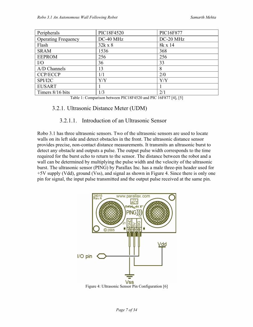
3.2.1.1. Introduction of an Ultrasonic Sensor Robo 3.1 has three ultrasonic sensors. Two of the ultrasonic sensors are used to locate walls on its left side and detect obstacles in the front. The ultrasonic distance sensor provides precise, non-contact distance measurements. It transmits an ultrasonic burst to detect any obstacle and outputs a pulse. The output pulse width corresponds to the time required for the burst echo to return to the sensor. The distance between the robot and a wall can be determined by multiplying the pulse width and the velocity of the ultrasonic burst. The ultrasonic sensor (PING) by Parallax Inc. has a male three-pin header used for +5V supply (Vdd), ground (Vss), and signal as shown in Figure 4. Since there is only one pin for signal, the input pulse transmitted and the output pulse received at the same pin.
Figure 4: Ultrasonic Sensor Pin Configuration [6]
Robo 3.1 An Autonomous Wall Following Robot Samarth Mehta
Page 8 of 34
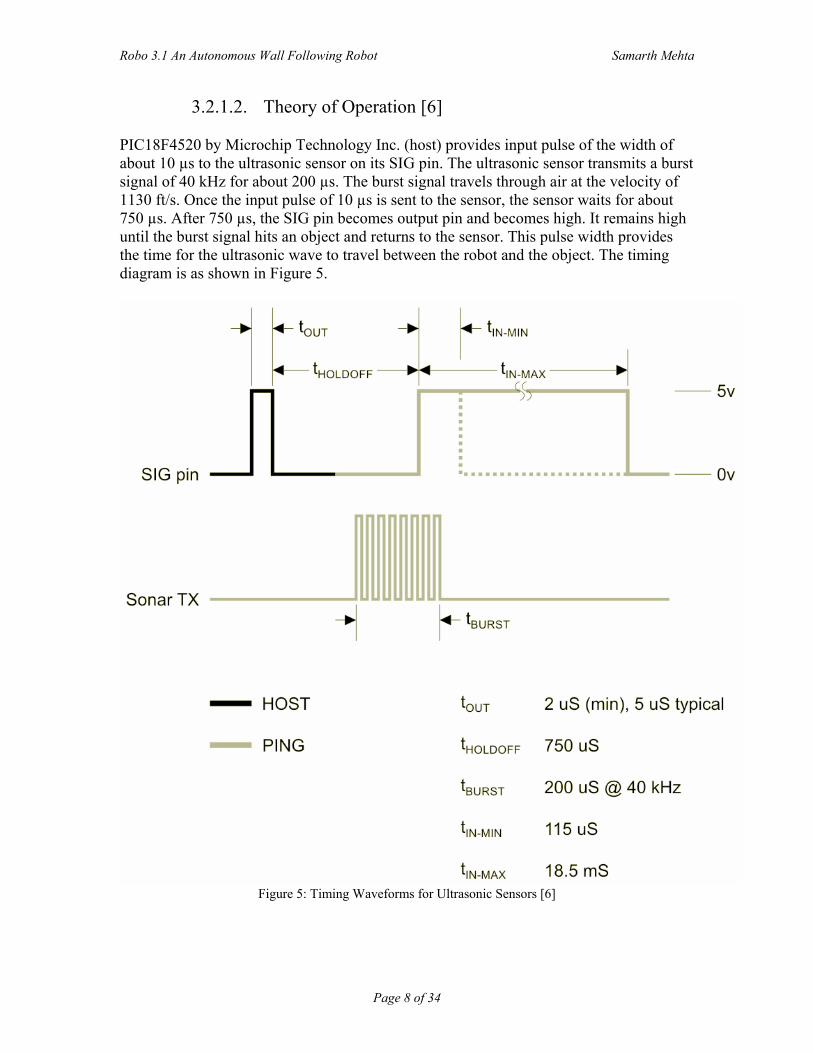
3.2.1.2. Theory of Operation [6] PIC18F4520 by Microchip Technology Inc. (host) provides input pulse of the width of about 10 µs to the ultrasonic sensor on its SIG pin. The ultrasonic sensor transmits a burst signal of 40 kHz for about 200 µs. The burst signal travels through air at the velocity of 1130 ft/s. Once the input pulse of 10 µs is sent to the sensor, the sensor waits for about 750 µs. After 750 µs, the SIG pin becomes output pin and becomes high. It remains high until the burst signal hits an object and returns to the sensor. This pulse width provides the time for the ultrasonic wave to travel between the robot and the object. The timing diagram is as shown in Figure 5.
Figure 5: Timing Waveforms for Ultrasonic Sensors [6]
Robo 3.1 An Autonomous Wall Following Robot Samarth Mehta
Page 9 of 34
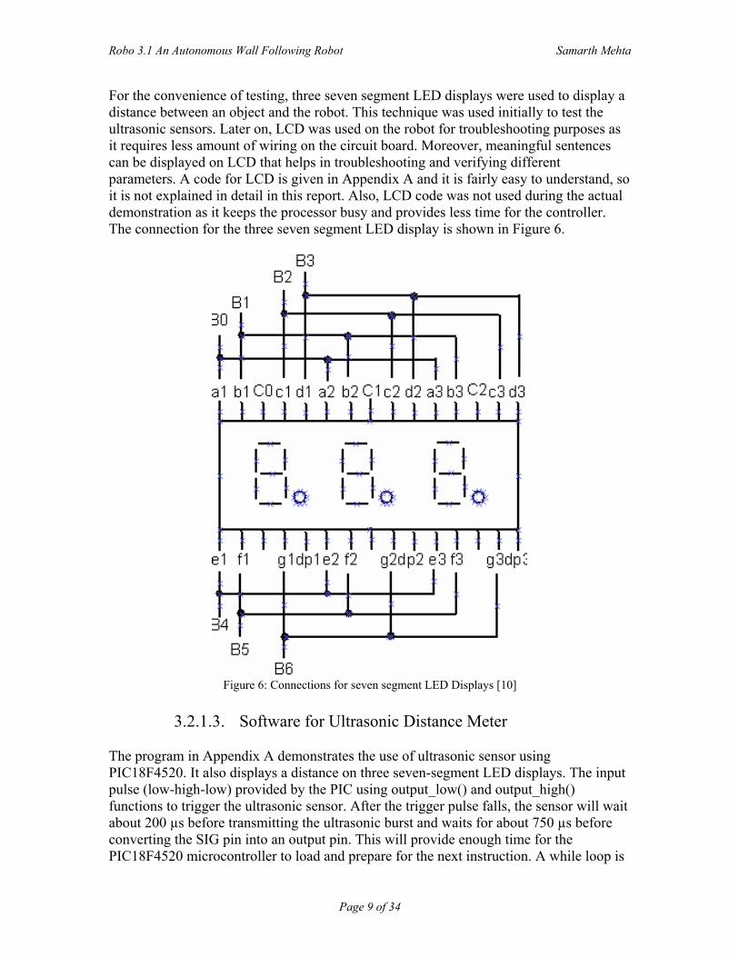
For the convenience of testing, three seven segment LED displays were used to display a distance between an object and the robot. This technique was used initially to test the ultrasonic sensors. Later on, LCD was used on the robot for troubleshooting purposes as it requires less amount of wiring on the circuit board. Moreover, meaningful sentences can be displayed on LCD that helps in troubleshooting and verifying different parameters. A code for LCD is given in Appendix A and it is fairly easy to understand, so it is not explained in detail in this report. Also, LCD code was not used during the actual demonstration as it keeps the processor busy and provides less time for the controller. The connection for the three seven segment LED display is shown in Figure 6.
Figure 6: Connections for seven segment LED Displays [10]
3.2.1.3. Software for Ultrasonic Distance Meter
The program in Appendix A demonstrates the use of ultrasonic sensor using PIC18F4520. It also displays a distance on three seven-segment LED displays. The input pulse (low-high-low) provided by the PIC using output_low() and output_high() functions to trigger the ultrasonic sensor. After the trigger pulse falls, the sensor will wait about 200 µs before transmitting the ultrasonic burst and waits for about 750 µs before converting the SIG pin into an output pin. This will provide enough time for the PIC18F4520 microcontroller to load and prepare for the next instruction. A while loop is
Robo 3.1 An Autonomous Wall Following Robot Samarth Mehta
Page 10 of 34
used to determine when to start the timer. The program control goes in the while loop and remains in it to check if output pin of ultrasonic sensor goes high. As soon as signal goes high, timer1 starts from 0. The Timer 1 interrupt is used to check an overflow. Once Timer 1 has started, program control goes in another while loop and stays there until output pin goes low. As soon as output signal goes low, the Timer 1 value is received using get_timer1() function. The raw time value from Timer 1 must be scaled due to overflow of Timer 1 and the overhead time consumed by the instructions. Also, the total time needs to be divided by two to remove the return trip of the echo pulse. display_number() function is used for displaying distance on the seven-segment display. To save pins on the microcontroller, multiplexing was used. In other words, each digit was displayed for 2 ms and this was done continuously in a loop. Due to the persistence of vision, display looks steady and all three digits can be viewed together.
3.2.2. Motors and driver circuit
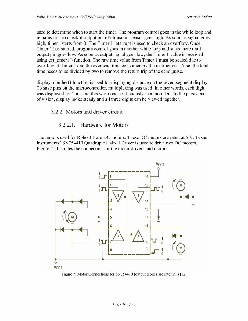
3.2.2.1. Hardware for Motors The motors used for Robo 3.1 are DC motors. These DC motors are rated at 5 V. Texas Instruments’ SN754410 Quadruple Half-H Driver is used to drive two DC motors. Figure 7 illustrates the connection for the motor drivers and motors.
Figure 7: Motor Connections for SN754410 (output diodes are internal.) [12]
Robo 3.1 An Autonomous Wall Following Robot Samarth Mehta
Page 11 of 34
As shown in Figure 7, SN754410 has four buffers and two enable pins. Each enable pin controls two buffers. These enable pins are controlled by the PIC18F4520 microcontroller. When these enable pins are high, the buffers turn on and when enable pins are low, the buffers turn off. By disabling the enable pins, the motors can be turned off. Pin 2 of Buffer 1 and Pin 7of Buffer 2 in SN754410 require PWM and complimentary PWM signals, respectively. Similarly, Pin 10 of Buffer 3 and Pin 15 of Buffer 4 require PWM and complimentary PWM signals, respectively. The PIC18F4520 is capable of providing only two PWM signals that are not complimentary of each other. Therefore, MC74HC00SN NAND gates were used as inverters to provide complimentary PWM signals. IC 7404 can be used instead of IC 7400. IC 7400 was used because of its availability in the lab. Motors are connected as shown on the left in Figure 7. Motors can also be connected as shown on the right in the above figure, but they can run only in one direction. Pin 16 of PIC18F4520 is connected to Pin 2 of the driver IC. Also, the PWM signal on Pin 2 of the driver IC is inverted and connected to Pin 7. Pin 17 of PIC18F4520 was similarly connected to Pin 15 of the driver IC and inverted PWM signal to the Pin 10 of the driver IC.
3.2.2.2. Software for Motors The program in Appendix A gives an example of PWM code that was tested to drive two motors. First, CCP1 and CCP2 are configured for PWM by using setup_ccp1(CCP_PWM) and setup_ccp2(CCP_PWM). Then, Timer 2 was configured by setup_timer_2(T2_DIV_BY_16, 255, 1). Here, the first argument is the mode. T2_DIV_BY_16 means divide the frequency by 16. Mode can be selected as 1, 4 or 16. The second argument indicates the period value. This number is used to determine the PWM period. Timer 2 counts up to the number defined in this second argument. The last argument is the postscale that determines how many timer overflows are allowed before an interrupt occurs. In order to set on time for the PWM signal, set_pwm1_duty (value) or set_pwm2_duty (value) can be used. Once Timer 2 reaches the number equal to the argument, the PWM output switches from high to low. The following equation gives the total PWM period [10].
PWMperiod )1(_241+×××= periodDIVT
clock (4)
In order to find the on time for a particular speed,
Ontime = %100
PWMperiodDutycycle× (5)
Robo 3.1 An Autonomous Wall Following Robot Samarth Mehta
Page 12 of 34
The relation between the speed of a motor at no load and duty cycle is
2100+
=SpeedDutycycle (6)
At 50% duty cycle, the speed of the motor is zero because of PWM and complimentary PWM signals. When duty cycle is over 50%, the speed is positive. On the other hand, when duty cycle is below 50%, the speed is negative. In other words, robot moves forward during the positive speed and backwards during the negative speed. The relation between PWM on time value and actual on time [10] is given by
DIVTclockOntimePWMontime
_21
4××= (7)
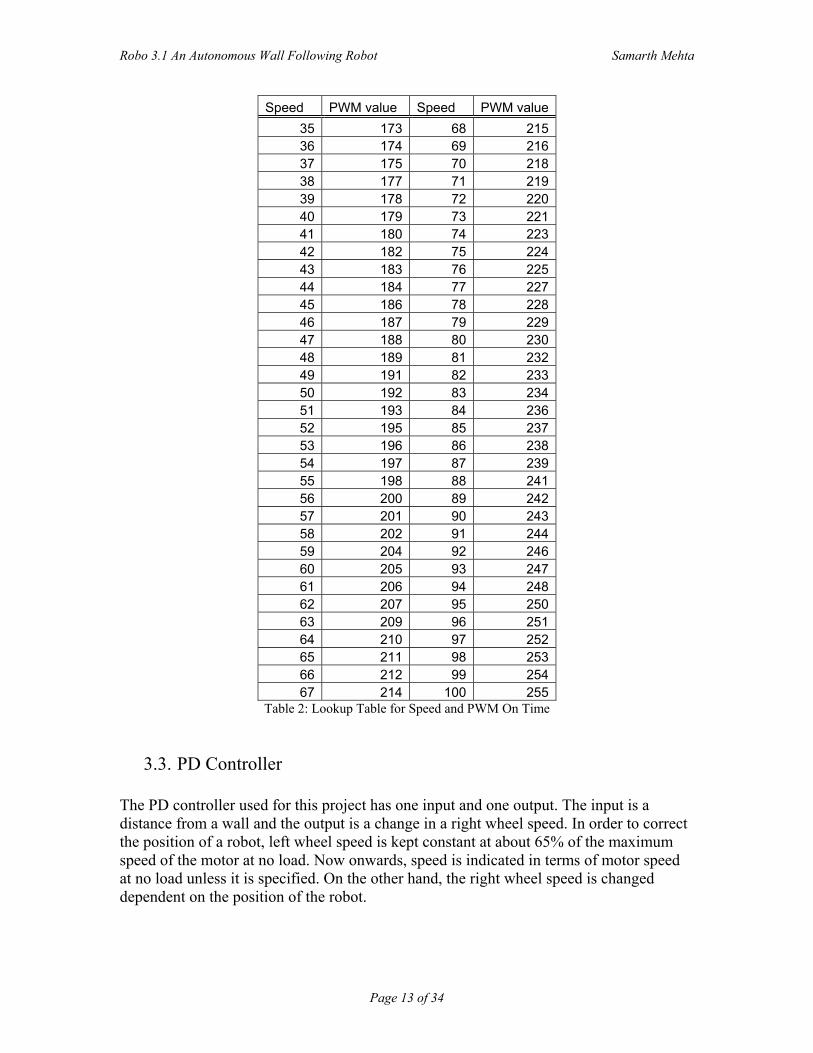
The following list provides the constants that are used for this project. clock = 40 MHz T2_DIV = 16 period = 255 PIC18F4520 was not able to handle these calculations as it requires at least 32 bit registers. Therefore, lookup table was used. Robo 3.1 hardly moves at the speed below 35% of the maximum speed of the motor. Therefore, the lookup table is developed for the speeds from 35% to 100% of the total speed of the motor. The lookup table is given in Table 2.
Robo 3.1 An Autonomous Wall Following Robot Samarth Mehta
Page 13 of 34
Speed PWM value Speed PWM value35 173 68 21536 174 69 21637 175 70 21838 177 71 21939 178 72 22040 179 73 22141 180 74 22342 182 75 22443 183 76 22544 184 77 22745 186 78 22846 187 79 22947 188 80 23048 189 81 23249 191 82 23350 192 83 23451 193 84 23652 195 85 23753 196 86 23854 197 87 23955 198 88 24156 200 89 24257 201 90 24358 202 91 24459 204 92 24660 205 93 24761 206 94 24862 207 95 25063 209 96 25164 210 97 25265 211 98 25366 212 99 25467 214 100 255
Table 2: Lookup Table for Speed and PWM On Time
3.3. PD Controller The PD controller used for this project has one input and one output. The input is a distance from a wall and the output is a change in a right wheel speed. In order to correct the position of a robot, left wheel speed is kept constant at about 65% of the maximum speed of the motor at no load. Now onwards, speed is indicated in terms of motor speed at no load unless it is specified. On the other hand, the right wheel speed is changed dependent on the position of the robot.
Robo 3.1 An Autonomous Wall Following Robot Samarth Mehta
Page 14 of 34
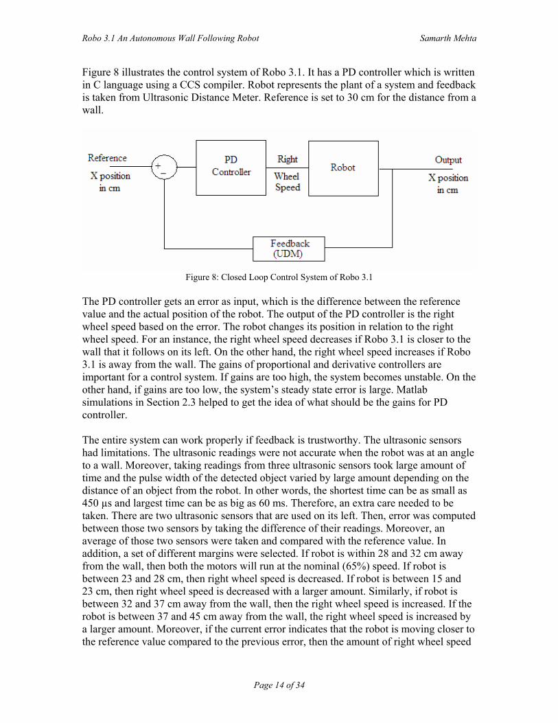
Figure 8 illustrates the control system of Robo 3.1. It has a PD controller which is written in C language using a CCS compiler. Robot represents the plant of a system and feedback is taken from Ultrasonic Distance Meter. Reference is set to 30 cm for the distance from a wall.
Figure 8: Closed Loop Control System of Robo 3.1
The PD controller gets an error as input, which is the difference between the reference value and the actual position of the robot. The output of the PD controller is the right wheel speed based on the error. The robot changes its position in relation to the right wheel speed. For an instance, the right wheel speed decreases if Robo 3.1 is closer to the wall that it follows on its left. On the other hand, the right wheel speed increases if Robo 3.1 is away from the wall. The gains of proportional and derivative controllers are important for a control system. If gains are too high, the system becomes unstable. On the other hand, if gains are too low, the system’s steady state error is large. Matlab simulations in Section 2.3 helped to get the idea of what should be the gains for PD controller. The entire system can work properly if feedback is trustworthy. The ultrasonic sensors had limitations. The ultrasonic readings were not accurate when the robot was at an angle to a wall. Moreover, taking readings from three ultrasonic sensors took large amount of time and the pulse width of the detected object varied by large amount depending on the distance of an object from the robot. In other words, the shortest time can be as small as 450 µs and largest time can be as big as 60 ms. Therefore, an extra care needed to be taken. There are two ultrasonic sensors that are used on its left. Then, error was computed between those two sensors by taking the difference of their readings. Moreover, an average of those two sensors were taken and compared with the reference value. In addition, a set of different margins were selected. If robot is within 28 and 32 cm away from the wall, then both the motors will run at the nominal (65%) speed. If robot is between 23 and 28 cm, then right wheel speed is decreased. If robot is between 15 and 23 cm, then right wheel speed is decreased with a larger amount. Similarly, if robot is between 32 and 37 cm away from the wall, then the right wheel speed is increased. If the robot is between 37 and 45 cm away from the wall, the right wheel speed is increased by a larger amount. Moreover, if the current error indicates that the robot is moving closer to the reference value compared to the previous error, then the amount of right wheel speed
Robo 3.1 An Autonomous Wall Following Robot Samarth Mehta
Page 15 of 34
decreased or increased is small. On the other hand if the current error indicates that the robot is moving away from the reference value as compared to the previous error, then the amount of right wheel speed decreased or increased is large. This explanation holds when front distance is greater than 100 cm. When front distance is less than 100 cm and robot is closer to the wall, the robot turns right for approximately 500 ms at 65% speed. On the other hand, if robot is too away from the wall, it turns left for approximately 250 ms at 65% speed. The ultrasonic sensors gives faulty readings several times, so if robot is within 15 cm from the wall, the robot turns left for approximately 250 ms at 65% speed. Similarly, if robot finds itself more than 45 cm away from the wall, it turns right for approximately 250 ms at 65% speed.
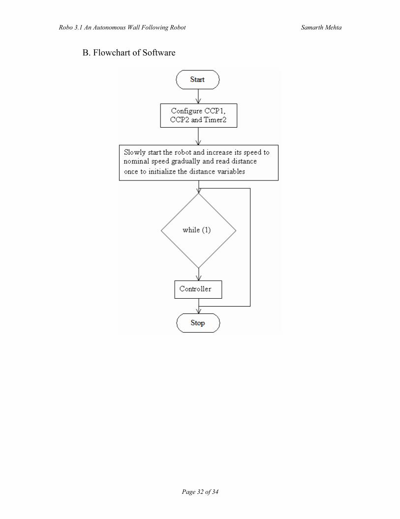
3.4. Integration of Software After knowing about how each of the components (motors, UDM and PD controller) work, it is essential to integrate all the software and execute them on right time for better performance. It is shown in the flowchart in Appendix B. When robot is switched on, the PIC18F4520 configures CCP1, CCP2 and Timer2 module for PWM signals. Then, robot starts slowly with 50% of the maximum speed of the motors at no load and increases its speed up to 65% of the maximum speed. Robo 3.1 also takes at least one ultrasonic reading to initialize ultrasonic distance variables. Next, PD controller part comes in the picture. Based on the distance variables, PD controller sets the right wheel speed. Then, PIC18F4520 reads the corresponding PWM on time value from the lookup table and sets the PWM on time. Once the PWM on time is set, PWM module controls the speed of the right wheel. The program control starts reading ultrasonic readings and based on these readings speed of the motors are calculated again. The procedure repeats continuously. 4. Conclusion
In this report, a differential drive mobile robot is presented which is controlled with the help of a PD controller to maintain a constant distance from the wall. Matlab simulations were carried out to get the overall idea of the problem. The robot successfully follows a wall. Hence, a PD controller is implemented and tested successfully. However, the robot could have followed a wall much smoothly if ultrasonic sensors gave accurate readings when robot was at an angle with the wall. Moreover, a few sensors can be mounted on the right side of the robot, so that robot can travel through narrow paths like in the corridor. A further research can be done where better sensors can be used. In addition, a 32 bit microcontroller or DSPIC can be used, so that calculations for on time of a PWM signal can be performed by the robot itself rather than looking up in a table. Also, a microcontroller that has more CCP modules can be used, so that ultrasonic sensors can be controlled through those modules along with the motors.
Robo 3.1 An Autonomous Wall Following Robot Samarth Mehta
Page 16 of 34
References [1] Chris Churavy, Maria Baker, Samarth Mehta, Ishu Pradhan, Nina Scheidegger, Steven Shanfelt, Rick Rarick, and Dan Simon, Cleveland State University, Department of Electrical and Computer Engineering, IEEE Potential (Unpublished), October 2007. [2] Mehmet Ergezer, Multivariable Control Methods for Wall Tracking Robot,
Cleveland State University, Department of Electrical and Computer Engineering, Project Paper, 2006.
[3] M.I.Rieiro , P.Lima, Kinematics Models of Mobile Robots, http://omni.isr.ist.utl.pt/~mir/cadeiras/robmovel/Kinematics.pdf, April 2002. [4] Microchip Inc., PIC16F87X Datasheet, www.microchip.com, 2001. [5] Microchip Inc., PIC18F2420/2520/4420/4520 Datasheet, www.microchip.com, 2007. [6] Parallax Inc., PING 28015 Datasheet, http://www.parallax.com/Portals/0/Downloads/docs/prod/acc/28015-PING- v1.5.pdf , February 2008 [7] R. Braunstingl, J. Mujika, J. P. Uribe, A wall following robot with a fuzzy logic controller optimized by a genetic algorithm, Fuzzy Systems 1995, vol. 5, pp 77-82, March 1995. [8] Robotic Swarms Project, http://embeddedlab.csuohio.edu/RoboticSwarms/, 2007 [9] Simple Wall Follower Robot and Code, http://www.cse.uta.edu/Robots/RobotCode.asp [10] Testing Kit using CCS Compiler, 2007 [11] Texas Instruments, SN754410 Datasheet, www.ti.com, November 1995. [12] Texas Instruments, L293D Datasheet, www.ti.com, November 2004. [13] Vamsi Mohan Peri, Fuzzy Logic Controller for an Autonomous Robot, Cleveland State University, Department of Electrical and Computer Engineering, Masters Thesis, 2005.
Robo 3.1 An Autonomous Wall Following Robot Samarth Mehta
Page 17 of 34
Appendices
A. Software Listing 1. Integrated code
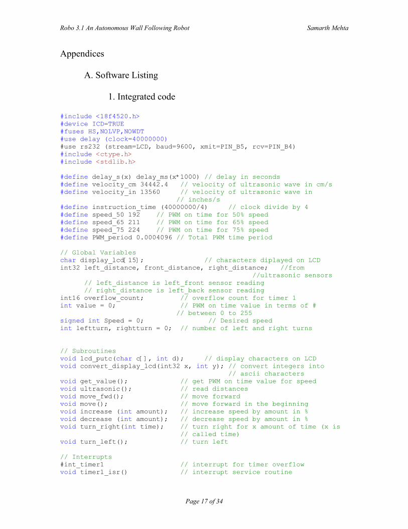
#include <18f4520.h> #device ICD=TRUE #fuses HS,NOLVP,NOWDT #use delay (clock=40000000) #use rs232 (stream=LCD, baud=9600, xmit=PIN_B5, rcv=PIN_B4) #include <ctype.h> #include <stdlib.h> #define delay_s(x) delay_ms(x*1000) // delay in seconds #define velocity_cm 34442.4 // velocity of ultrasonic wave in cm/s #define velocity_in 13560 // velocity of ultrasonic wave in // inches/s #define instruction_time (40000000/4) // clock divide by 4 #define speed_50 192 // PWM on time for 50% speed #define speed_65 211 // PWM on time for 65% speed #define speed_75 224 // PWM on time for 75% speed #define PWM_period 0.0004096 // Total PWM time period // Global Variables char display_lcd[15]; // characters diplayed on LCD int32 left_distance, front_distance, right_distance; //from
//ultrasonic sensors // left_distance is left_front sensor reading // right_distance is left_back sensor reading int16 overflow_count; // overflow count for timer 1 int value = 0; // PWM on time value in terms of # // between 0 to 255 signed int Speed = 0; // Desired speed int leftturn, rightturn = 0; // number of left and right turns // Subroutines void lcd_putc(char c[], int d); // display characters on LCD void convert_display_lcd(int32 x, int y); // convert integers into
// ascii characters void get_value(); // get PWM on time value for speed void ultrasonic(); // read distances void move_fwd(); // move forward void move(); // move forward in the beginning void increase (int amount); // increase speed by amount in % void decrease (int amount); // decrease speed by amount in % void turn_right(int time); // turn right for x amount of time (x is
// called time) void turn_left(); // turn left // Interrupts #int_timer1 // interrupt for timer overflow void timer1_isr() // interrupt service routine
Robo 3.1 An Autonomous Wall Following Robot Samarth Mehta
Page 18 of 34
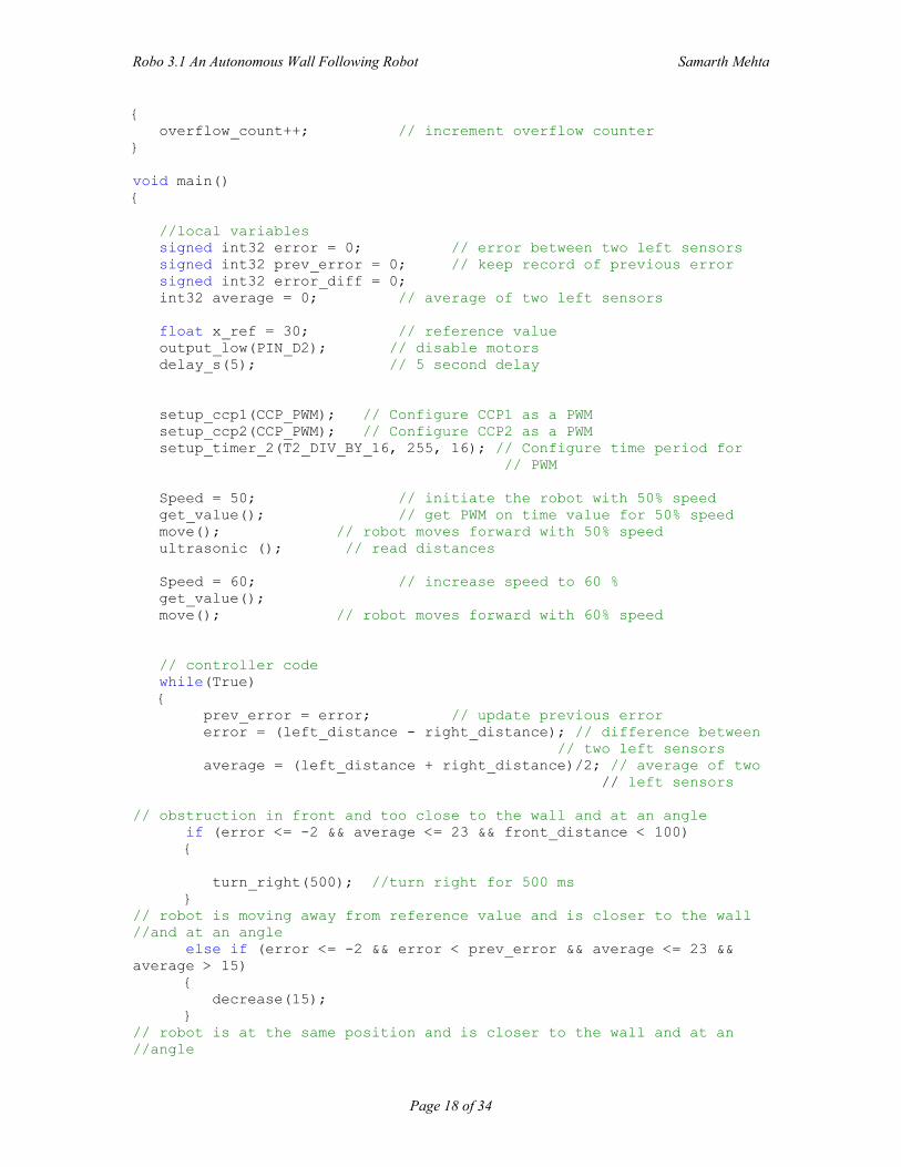
{ overflow_count++; // increment overflow counter } void main() { //local variables signed int32 error = 0; // error between two left sensors signed int32 prev_error = 0; // keep record of previous error signed int32 error_diff = 0; int32 average = 0; // average of two left sensors float x_ref = 30; // reference value output_low(PIN_D2); // disable motors delay_s(5); // 5 second delay setup_ccp1(CCP_PWM); // Configure CCP1 as a PWM setup_ccp2(CCP_PWM); // Configure CCP2 as a PWM setup_timer_2(T2_DIV_BY_16, 255, 16); // Configure time period for
// PWM Speed = 50; // initiate the robot with 50% speed get_value(); // get PWM on time value for 50% speed move(); // robot moves forward with 50% speed ultrasonic (); // read distances Speed = 60; // increase speed to 60 % get_value(); move(); // robot moves forward with 60% speed // controller code while(True) { prev_error = error; // update previous error error = (left_distance - right_distance); // difference between
// two left sensors average = (left_distance + right_distance)/2; // average of two // left sensors
// obstruction in front and too close to the wall and at an angle if (error <= -2 && average <= 23 && front_distance < 100) { turn_right(500); //turn right for 500 ms } // robot is moving away from reference value and is closer to the wall //and at an angle else if (error <= -2 && error < prev_error && average <= 23 && average > 15) { decrease(15); } // robot is at the same position and is closer to the wall and at an //angle
Robo 3.1 An Autonomous Wall Following Robot Samarth Mehta
Page 19 of 34
else if (error <= -2 && error == prev_error && average <= 23 && average > 15) { decrease(0); } // robot is moving closer to the reference value and is closer to the //wall and at an angle else if (error <= -2 && error > prev_error && average <= 23 && average > 15) { decrease(5); } // robot is moving away from reference value and is closer to the wall else if (error < prev_error && average < 28 && average > 23 ) { decrease(10); } // robot is moving closer to reference value and is closer to the wall else if (error > prev_error && average < 28 && average > 23 ) { decrease(5); } // robot is at the same position and is closer to the wall else if (error == prev_error && average < 28 && average > 23 ) { decrease(0); } // obstruction in front and too away from the wall and at an angle else if ( error >= 2 && error > prev_error && average >= 37 && front_distance < 100 ) { turn_left(); } // robot is moving away from the reference value and is away from the //wall and at an angle else if (error >= 2 && error > prev_error && average > 37 && average < 45) { increase(10); } // robot is at the same position and is away from the wall and at an //angle else if (error >= 2 && error == prev_error && average > 37 && average < 45) { increase(0); } // robot is moving closer to the reference value and is away from the //wall and is at an angle else if (error >= 2 && error < prev_error && average > 37 && average < 45) { increase(5); } // robot is moving away from the reference value and is away from the //wall else if ( error > prev_error && average > 32 && average < 37 )
Robo 3.1 An Autonomous Wall Following Robot Samarth Mehta
Page 20 of 34
{ increase(10); } // robot is moving closer to the reference value and is away from the // wall else if ( error < prev_error && average > 32 && average < 37 ) { increase(5); } // robot is at the same position and is away from the wall else if ( error == prev_error && average > 32 && average < 37 ) { increase(0); } // robot is at an angle less than 90 degrees with respect to x axis and // closer to the wall else if (error >= 2 && error > prev_error && average < 15) { increase(1); } // robot is at an angle greater than 90 degrees with respect to x axis // and closer to the wall else if (error >= 2 && error < prev_error && average < 15 ) { decrease(1); } // robot is at an angle greater than 90 degrees with respect to x axis // and away from the wall else if (error >= 2 && error > prev_error && average > 45) { decrease(10); } // if robot is too close to the wall decrease right wheel speed by the // largest amount, //However, it's been checked again after this sequence and corrected by // a turn. else if (error >= 2 && error < prev_error && average < 15 ) { decrease(20); } // for minor corrections in angle else if (error<=-2) { decrease(1); } // for minor corrections in angle else if (error>=2) { increase(1); } // else nominal speed when robot is between 28 and 32 cm away from the // wall else { Speed = 65; get_value(); move_fwd(); // set right wheel speed to 65%
Robo 3.1 An Autonomous Wall Following Robot Samarth Mehta
Page 21 of 34
} // robot is too close to the wall (for immediate correction) if (average < 20 ) { turn_right(250); } // obstruction detected in front and robot is between 28 and 32 cm else if (front_distance <= 50 ) { turn_right(500); } // robot is too away from the wall (for immediate correction) else if (average > 40 ) { turn_left(); } // else nominal speed when robot is between 28 and 32 cm away from the // wall else { Speed = 65; get_value(); move_fwd(); // increase right wheel speed to 75% } } } void turn_right(int time) { if (rightturn <= 2) { set_pwm1_duty(speed_65); // This sets the on time for PIN # // 17(left motor) nominal speed set_pwm2_duty(45); // This sets the on time for PIN #
// 16(right motor) output_high(PIN_D2); // enable motors delay_ms(time); output_low(PIN_D2); // disable motors ultrasonic(); // get UDM reading rightturn++; // increment right turn count } else { rightturn = 0; // reset the right turn count Speed = 65; // set nominal speed get_value(); move_fwd(); // move forward } } void turn_left() { if(leftturn <= 2) { set_pwm1_duty(45); // This sets the on time for PIN #
// 17(left motor)nominal speed
Robo 3.1 An Autonomous Wall Following Robot Samarth Mehta
Page 22 of 34
set_pwm2_duty(speed_65); // This sets the on time for PIN # // 16(right motor)
output_high(PIN_D2); // enable motors delay_ms(250); output_low(PIN_D2); // disable motors ultrasonic(); // get UDM reading leftturn++; // increment left turn count } else { leftturn = 0; // reset left turn count Speed = 65; // set nominal speed get_value(); move_fwd(); // move forward } } void decrease(int amount) { Speed = Speed - amount; // decrease speed by the amount get_value(); move_fwd(); // decrease right wheel speed } void increase (int amount) { Speed = Speed + amount; // increase speed by the amount get_value(); move_fwd(); // increase right wheel speed } void get_value() // lookup table for PWM on time { int32 temp_value = 0; if (Speed == 0) value = 128; else if (Speed < 35) value = 160; else if (Speed == 35) value = 173; else if (Speed == 36) value = 174; else if (Speed == 37) value = 175; else if (Speed == 38) value = 177; else if (Speed == 39) value = 178; else if (Speed == 40) value = 179; else if (Speed == 41) value = 180; else if (Speed == 42) value = 182; else if (Speed == 43) value = 183;
Robo 3.1 An Autonomous Wall Following Robot Samarth Mehta
Page 23 of 34
else if (Speed == 44) value = 184; else if (Speed == 45) value = 186; else if (Speed == 46) value = 187; else if (Speed == 47) value = 188; else if (Speed == 48) value = 189; else if (Speed == 49) value = 191; else if (Speed == 50) value = 192; else if (Speed == 51) value = 193; else if (Speed == 52) value = 195; else if (Speed == 53) value = 196; else if (Speed == 54) value = 197; else if (Speed == 55) value = 198; else if (Speed == 56) value = 200; else if (Speed == 57) value = 201; else if (Speed == 58) value = 202; else if (Speed == 59) value = 204; else if (Speed == 60) value = 205; else if (Speed == 61) value = 206; else if (Speed == 62) value = 207; else if (Speed == 63) value = 209; else if (Speed == 64) value = 210; else if (Speed == 65) value = 211; else if (Speed == 66) value = 212; else if (Speed == 67) value = 214; else if (Speed == 68) value = 215; else if (Speed == 69) value = 216; else if (Speed == 70) value = 218; else if (Speed == 71) value = 219; else if (Speed == 72)
Robo 3.1 An Autonomous Wall Following Robot Samarth Mehta
Page 24 of 34
value = 220; else if (Speed == 73) value = 221; else if (Speed == 74) value = 223; else if (Speed == 75) value = 224; else if (Speed == 76) value = 225; else if (Speed == 77) value = 227; else if (Speed == 78) value = 228; else if (Speed == 79) value = 229; else if (Speed == 80) value = 230; else if (Speed == 81) value = 232; else if (Speed == 82) value = 233; else if (Speed == 83) value = 234; else if (Speed == 84) value = 236; else if (Speed == 85) value = 237; else if (Speed == 86) value = 238; else if (Speed == 87) value = 239; else if (Speed == 88) value = 241; else if (Speed == 89) value = 242; else if (Speed == 90) value = 243; else if (Speed == 91) value = 244; else if (Speed == 92) value = 246; else if (Speed == 93) value = 247; else if (Speed == 94) value = 248; else if (Speed == 95) value = 250; else if (Speed == 96) value = 251; else if (Speed == 97) value = 252; else if (Speed == 98) value = 253; else if (Speed == 99) value = 254; else if (Speed >= 100) value = 255;
Robo 3.1 An Autonomous Wall Following Robot Samarth Mehta
Page 25 of 34
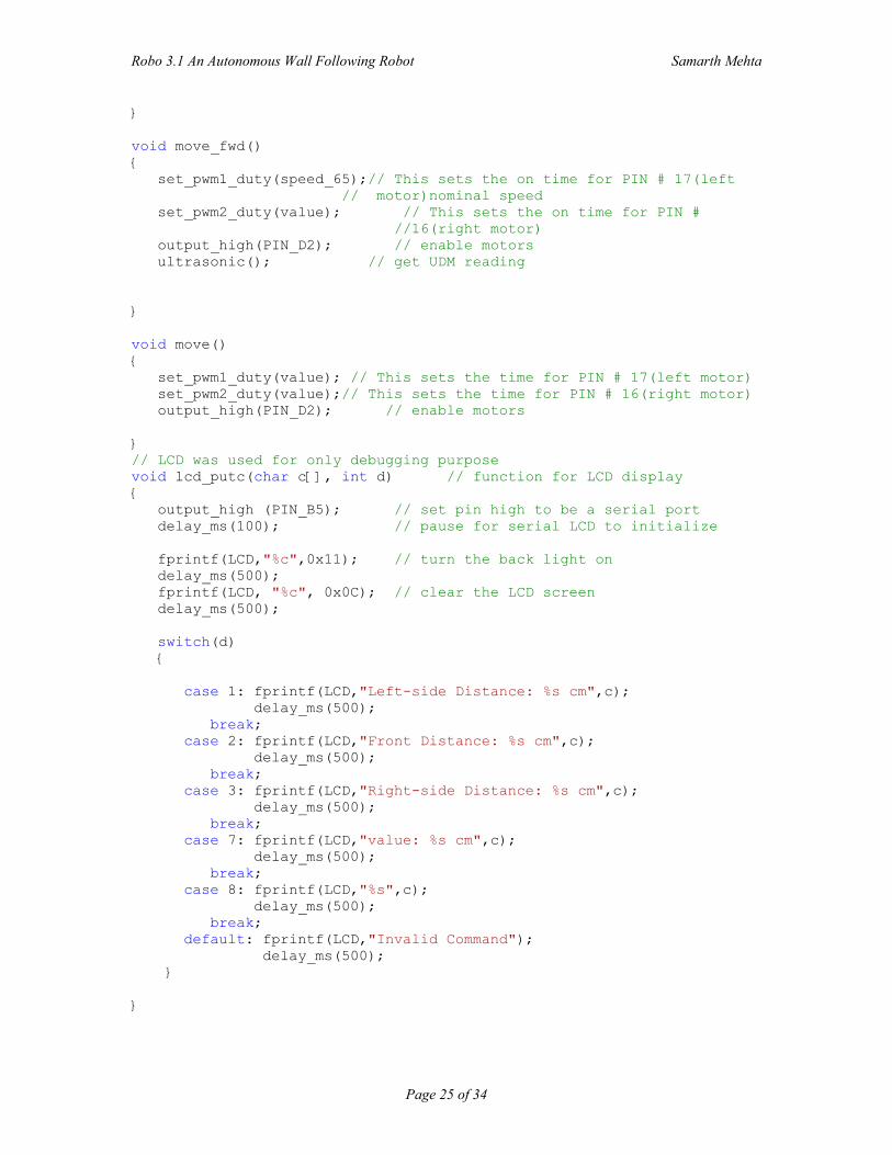
} void move_fwd() { set_pwm1_duty(speed_65);// This sets the on time for PIN # 17(left // motor)nominal speed set_pwm2_duty(value); // This sets the on time for PIN # //16(right motor) output_high(PIN_D2); // enable motors ultrasonic(); // get UDM reading } void move() { set_pwm1_duty(value); // This sets the time for PIN # 17(left motor) set_pwm2_duty(value);// This sets the time for PIN # 16(right motor) output_high(PIN_D2); // enable motors } // LCD was used for only debugging purpose void lcd_putc(char c[], int d) // function for LCD display { output_high (PIN_B5); // set pin high to be a serial port delay_ms(100); // pause for serial LCD to initialize fprintf(LCD,"%c",0x11); // turn the back light on delay_ms(500); fprintf(LCD, "%c", 0x0C); // clear the LCD screen delay_ms(500); switch(d) { case 1: fprintf(LCD,"Left-side Distance: %s cm",c); delay_ms(500); break; case 2: fprintf(LCD,"Front Distance: %s cm",c); delay_ms(500); break; case 3: fprintf(LCD,"Right-side Distance: %s cm",c); delay_ms(500); break; case 7: fprintf(LCD,"value: %s cm",c); delay_ms(500); break; case 8: fprintf(LCD,"%s",c); delay_ms(500); break; default: fprintf(LCD,"Invalid Command"); delay_ms(500); } }
Robo 3.1 An Autonomous Wall Following Robot Samarth Mehta
Page 26 of 34
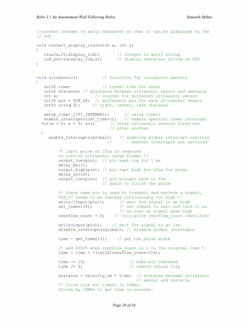
//convert integer to ascii character so that it can be displayed on the // LCD void convert_display_lcd(int32 x, int y) { itoa(x,10,display_lcd); // integer to ascii string lcd_putc(display_lcd,y); // display character string on LCD } void ultrasonic() // fuinction for ultrasonic sensors { int32 time; // travel time for sonar int32 distance; // disctance between ultrasonic sensor and obstacle int x; // counter for different ultrasonic sensor int32 pin = PIN_D4; // differenct pin for each ultrasonic sensor int32 ultra[3]; // right, center, left distance setup_timer_1(T1_INTERNAL); // using timer1 enable_interrupts(int_timer1); // enable specific timer interrupt for(x = 0; x < 3; x++) // three ultrasonic sensors fired one
// after another { enable_interrupts(global); // enabling global interrupt controls // whether interrupts are serviced /* input pulse of 10us is required to turn-on ultrasonic range finder */ output_low(pin); // pin kept low for 1 ms delay_ms(1); output_high(pin); // pin kept high for 10us for pulse delay_us(10); output_low(pin); // pin brought back to low // again to finish the pulse /* Since same pin is used to transmit and recieve a signal, PIN_C7 needs to be checked continuously for high */ while(!input(pin)); // wait for signal to go high set_timer1(0); // set timer1 to zero and turn it on // as soon as signal goes high overflow_count = 0; // initialize overflow_count identifier while(input(pin)); // wait for signal to go low disable_interrupts(global); // disable global interrupts time = get_timer1(); // get the pulse width /* add 65535 when overflow_count is 1 to the original time */ time = time + ((int32)overflow_count<<16); time -= 15; // subtract overhead time /= 2; // remove return trip distance = velocity_cm * time; // distance between ultrasonic // sensor and obstacle /* clock tick for timer1 is 10MHz. divide by 10MHz to get time in seconds.
Robo 3.1 An Autonomous Wall Following Robot Samarth Mehta
Page 27 of 34
division in the end gives less error, since more significant numbers can give closer value */ distance /= instruction_time; // get original distance in cm ultra[x] = distance; pin++; } left_distance = ultra[0]; // left_front distance front_distance = ultra[1]; // front distance right_distance = ultra[2]; // left_back distance }
2. Code for Motor and PWM signal (Test Version) [10] (Note: Notice the clock speed.)
#include <18F4520.h> #device ICD = TRUE #fuses HS,NOWDT,NOPROTECT,NOLVP #use delay(clock=3686400) #use rs232 (DEBUGGER) void main() { float desired = 50; float calculated = 0; int value = 0; setup_ccp1(CCP_PWM); // Configure CCP1 as a PWM setup_ccp2(CCP_PWM); // Configure CCP2 as a PWM // The cycle time will be (1/clock)*4*t2div*(period+1) // In this program clock=3686400 and period=63 (below) // selections the cycle time is: // (1/3.6M)*4*1*64 = 69.4 us or 14.4 khz setup_timer_2(T2_DIV_BY_1, 127, 1); calculated = (desired+100)/2; value = 1.28 * calculated; set_pwm1_duty(value); // This sets the time the pulse is // high each cycle.
// the high time will be: // if value is INT: // value*4*(1/clock)*t2div
// for example a value of 30 and t2div // of 1 the high time is 12us set_pwm2_duty(value); } //main
Robo 3.1 An Autonomous Wall Following Robot Samarth Mehta
Page 28 of 34
3. Code for Ultrasonic (Test version) [10] (Note: Notice the clock speed.)
#include <18F4520.h> /* pic 18f4520 */ #fuses HS,NOWDT,NOPROTECT,NOLVP /* basic hardware */ #use delay(clock=20000000) /* 20MHz clock */ #use rs232(baud=9600, xmit=PIN_C6, rcv=PIN_C7) #include <ctype.h> #define clock 20000000 #define velocity_cm 34442.4 /* velocity of ultrasonic wave in cm/s */ #define velocity_in 13560 /*velocity of ultrasonic wave in inches/s */ #define instruction_time clock/4 /* hex code for lighting LEDs in seven-segment display corresponding to the numbers */ byte CONST LED_MAP[10] = {0x3f,0x06,0x5b,0x4f,0x66,0x6d,0x7d,0x07,0x7f,0x67}; int16 overflow_count; #int_timer1 /* interrupt for timer overflow */ void timer1_isr() /* interrupt service routine */ { overflow_count++; /* increment overflow counter */ } void display_number(int32 n) /* display for distance measurement on 3-digit seven-segment LED display */ { int32 i = 0; output_b(LED_MAP[n/100]); /* leftmost (first) seven-segment display */ output_low(PIN_C0); /* turn-on leftmost seven-segment LED display and keep others off */ delay_ms(2); output_high(PIN_C0); /* turn-off leftmost LED display */ i = n%100; output_b(LED_MAP[i/10]); /* centeral (second) seven-segment display */ output_low(PIN_C1); /* turn-on centeral seven-segment LED display and keep others off */ delay_ms(2); output_high(PIN_C1); /* turn-off central LED display */ output_b(LED_MAP[i%10]); /* rightmost (third) seven-segment display */ output_low(PIN_C2); /* turn-on rightmost seven-segment LED display and keep others off */ delay_ms(2); output_high(PIN_C2); /* turn-off rightmost LED display */ }
Robo 3.1 An Autonomous Wall Following Robot Samarth Mehta
Page 29 of 34
void main() { int32 time; int32 distance; setup_timer_1(T1_INTERNAL); /* using timer1 */ enable_interrupts(int_timer1); /* enable specific timer interrupt */ delay_ms(5000); /* 5 sec delay in the beginning to give enough time to hardware to get ready */ do { int32 c; enable_interrupts(global); /* enabling global interrupt controls whether interrupts are serviced */ /* input pulse of 10us is required to turn-on ultrasonic range finder */ output_low(PIN_C3); /* PIN_C3 kept low for 1 ms */ delay_ms(1); output_high(PIN_C3); /* PIN_C3 kept high for 10us for pulse */ delay_us(10); output_low(PIN_C3); /* PIN_C3 brought back to low again to finish the pulse */ /* Since same pin is used to transmit and recieve a signal, PIN_C3 needs to be checked continuously for high */ while(!input(PIN_C3)); /* wait for signal to go high */ set_timer1(0); /* set timer1 to zero and turn it on as soon as signal goes high */ overflow_count = 0; /* initialize overflow_count identifier */ while(input(PIN_C3)); /* wait for signal to go low */ disable_interrupts(global); /* disable global interrupts */ time = get_timer1(); /* get the pulse width */ /* add 65535 when overflow_count is 1 to the original time */ time = time + ((int32)overflow_count<<16); time -= 15; /* subtract overhead */ time /= 2; /* remove return trip */ distance = velocity_cm * time; /* distance between ultrasonic sensor and obstacle */ /* clock tick for timer1 is 5MHz. divide by 5MHz to get time in seconds. division in the end gives less error, since more significant numbers can give closer value */ distance /= instruction_time;
Robo 3.1 An Autonomous Wall Following Robot Samarth Mehta
Page 30 of 34
for(c = 0; c <= 200; c++) display_number(distance); /* display number on 7-segment
display */ } while (TRUE); }
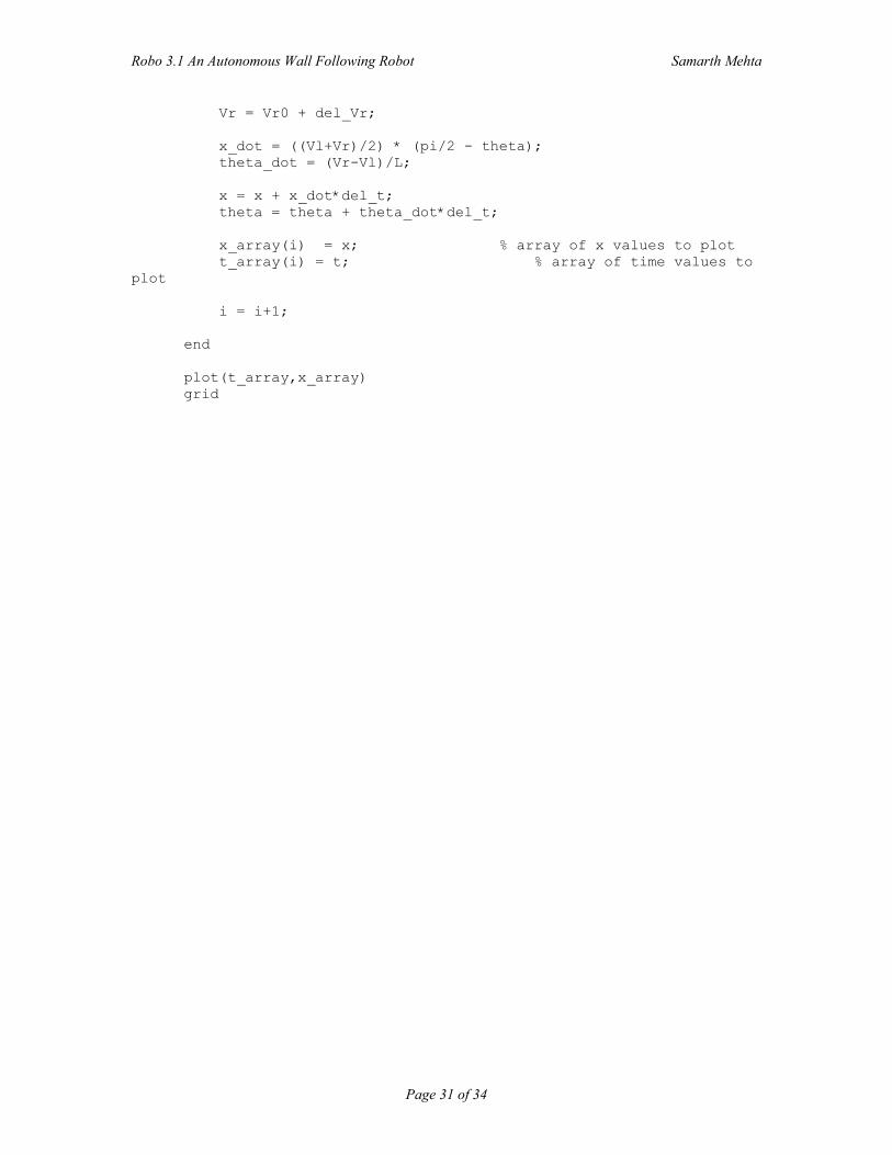
4. Matlab Simulation Code % Initial Conditions theta = pi/2 % angle between robots vertical axis and x axis Vr0 = 9.14 % Right wheel speed x = 15 ; % Distance between wall and the robot % Constants K = 0.5; % proportional constant D = 150; % Dervative constant I = 0; % Integral constant L = 18.5; % distance between two wheels Vl = Vr0 % Left wheel speed del_t = .02; % Time interval between 2 UDM readings x_ref = 20; % Reference distance of 20 cm final_t = 20; % final time array_size = ceil(final_t/10*del_t) % array size for x position
and time %Initialized Variables x_array = zeros(1,array_size) % array for x values t_array = zeros(1,array_size) % array for time values e = 0; % error i = 1; % count for array indices integral_control = 0; % integral controller gain for t = 0: del_t: final_t % for loop % Formula for change in x position prev_e = e; % error(t-delta_t) e = x_ref - x; del_e = e - prev_e; % delta_e = error - error(t-
delta_t) prev_integral_control = integral_control; % sum of old integral control intgral_control = prev_integral_control + I*del_e* del_t; %Controller del_Vr = -K*e - D*del_e - integral_control; % delta_Vr
Robo 3.1 An Autonomous Wall Following Robot Samarth Mehta
Page 31 of 34
Vr = Vr0 + del_Vr; x_dot = ((Vl+Vr)/2) * (pi/2 - theta); theta_dot = (Vr-Vl)/L; x = x + x_dot*del_t; theta = theta + theta_dot*del_t; x_array(i) = x; % array of x values to plot t_array(i) = t; % array of time values to
plot i = i+1; end plot(t_array,x_array) grid
Robo 3.1 An Autonomous Wall Following Robot Samarth Mehta
Page 32 of 34
B. Flowchart of Software
Robo 3.1 An Autonomous Wall Following Robot Samarth Mehta
Page 33 of 34
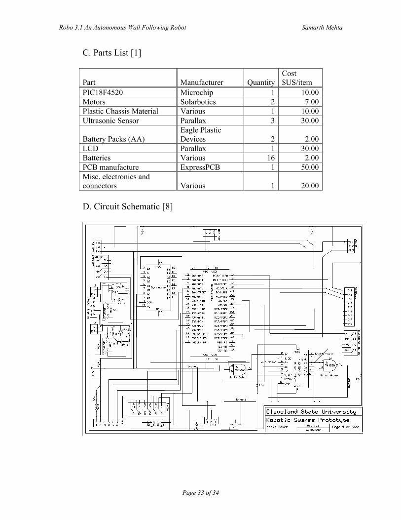
C. Parts List [1]
Part Manufacturer QuantityCost $US/item
PIC18F4520 Microchip 1 10.00 Motors Solarbotics 2 7.00 Plastic Chassis Material Various 1 10.00 Ultrasonic Sensor Parallax 3 30.00
Battery Packs (AA) Eagle Plastic Devices 2 2.00
LCD Parallax 1 30.00 Batteries Various 16 2.00 PCB manufacture ExpressPCB 1 50.00 Misc. electronics and connectors Various 1 20.00 D. Circuit Schematic [8]


![[ , ] Autonomous Human Robot Interactive Skills](https://static.fdocuments.us/doc/165x107/577cc35f1a28aba71195d883/-autonomous-human-robot-interactive-skills.jpg)