
ROBIN - Jacks Small Engines engines... · robin america, inc. ... ey08 ey15 ey 15v ey20 ey2ov ey23...
19
Transcript of ROBIN - Jacks Small Engines engines... · robin america, inc. ... ey08 ey15 ey 15v ey20 ey2ov ey23...
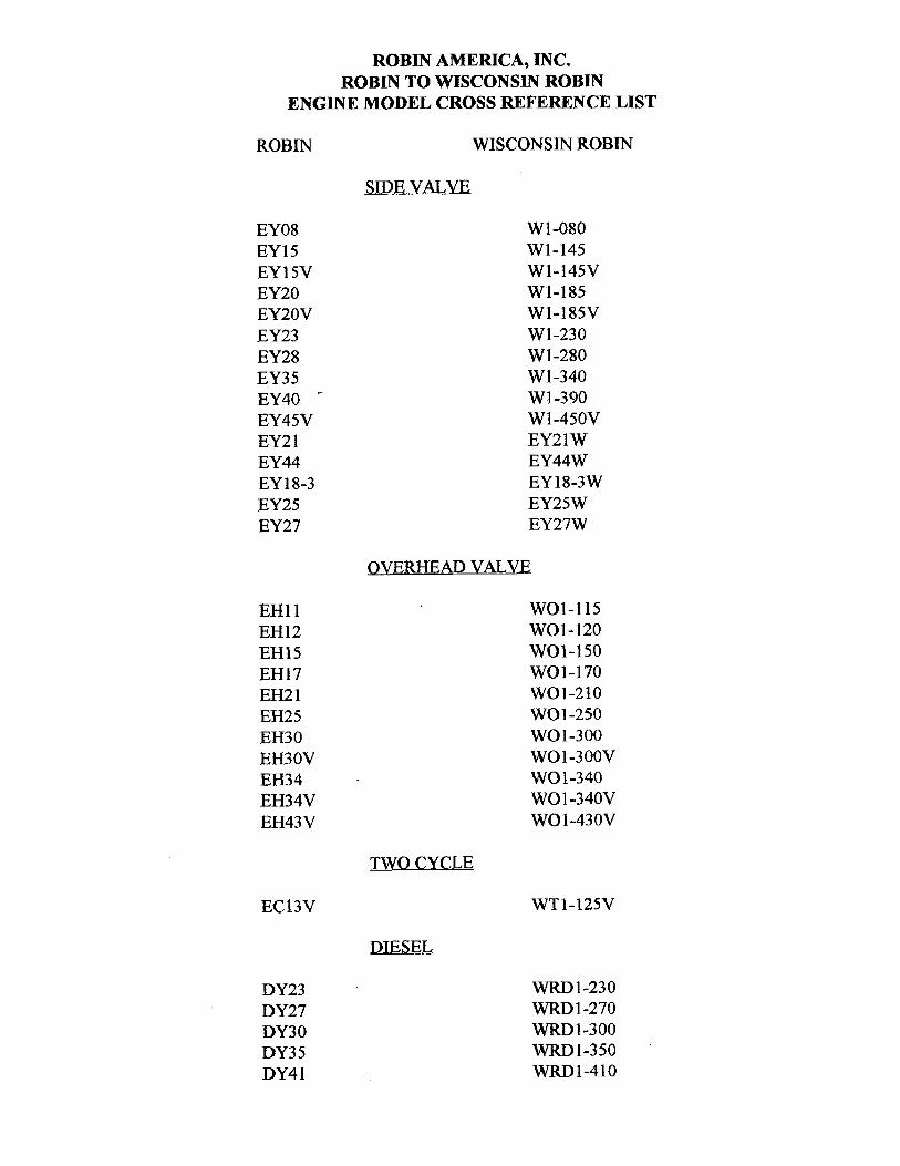
ROBIN AMERICA, INC. ROBIN TO WISCONSIN ROBIN
ENGINE MODEL CROSS REFERENCE LIST
ROBIN
EY08 EY15 EY 15V EY20 EY2OV EY23 EY28 EY3 5 EY40 - EY45V EY2 1 EY44 EY 18-3 EY25 EY27
EH11 EH12 EH15 EH17 EH21 EH25 EH30 EH30V EH34 EH34V EH43V
EC13V
DY23 DY27 DY30 DY3 5 DY4 1
WISCONSIN ROBIN
SIDE VALVE
W 1-080 W1-145 W1-145V W1-185 W1-185V W1-230 W 1-280 W 1-340 W 1-390 Wl-45OV EY21W EY44W EY18-3W EY25W EY27W
OVERHEAD VALVE
WO1-115 wo1-120 WO1-150 WO1-170 wo1-210 WOl-250 WO 1-300 WO1-300V WO1-340 WO 1 -340V WO 1-43 OV
TWO CYCLE
WT1-125V
DIESEL
WRD 1-230 WRD 1-270 -1-300 WRD1-350 WRD1-410
0
0
0
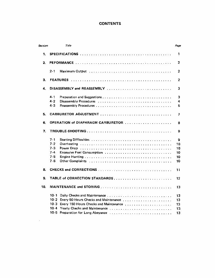
CONTENTS
Section Title Page
1 . SPECIFICATIONS . . . . . . . . . . . . . . . . . . . . . . . . . . . . . . . . . . . . . . . . . 1
2 . PEFORMANCE . . . . . . . . . . . . . . . . . . . . . . . . . . . . . . . . . . . . . . . . . . . 2
2-1 MaximumOutput . . . . . . . . . . . . . . . . . . . . . . . . . . . . . . . . . . . . . 2
3 . FEATURES . . . . . . . . . . . . . . . . . . . . . . . . . . . . . . . . . . . . . . . . . . . . . 2
4 . DISASSEMBLY and REASSEMBLY . . . . . . . . . . . . . . . . . . . . . . . . . . . . . 3
4-1 Preparation and Suggestions . . . . . . . . . . . . . . . . . . . . . . . . . . . . . . . 3 4-2 Disassembly Procedures . . . . . . . . . . . . . . . . . . . . . . . . . . . . . . . . . 4 4-3 Reassembly Procedures . . . . . . . . . . . . . . . . . . . . . . . . . . . . . . . . . . 5
5 . CARBURETOR ADJUSTMENT . . . . . . . . . . . . . . . . . . . . . . . . . . . . . . . . 7
6 . OPERATION of DIAPHRAGM CARBURETOR . . . . . . . . . . . . . . . . . . . . . 8
7 . TROUBLE-SHOOTING . . . . . . . . . . . . . . . . . . . . . . . . . . . . . . . . . . . . . . 9
7-1 Starting Difficulties . . . . . . . . . . . . . . . . . . . . . . . . . . . . . . . . . . . . 9 7-2 Overheating . . . . . . . . . . . . . . . . . . . . . . . . . . . . . . . . . . . . . . . . . 10 7-3 Power Drop . . . . . . . . . . . . . . . . . . . . . . . . . . . . . . . . . . . . . . . . . 10 7-4 Excessive Fuel Consumption . . . . . . . . . . . . . . . . . . . . . . . . . . . . . . 10 7-5 Engine Hunting . . . . . . . . . . . . . . . . . . . . . . . . . . . . . . . . . . . . . . . 10 7-6 Other Complaints . . . . . . . . . . . . . . . . . . . . . . . . . . . . . . . . . . . . . 10
8 . CHECKS and CORRECTIONS . . . . . . . . . . . . . . . . . . . . . . . . . . . . . . . . . 1-1
9 . TABLE of CORRECTION STANDARDS . . . . . . . . . . . . . . . . . . . . . . . . . . 12
10 . MAINTENANCE and STORING . . . . . . . . . . . . . . . . . . . . . . . . . . . . . . . . 13
10-1 Daily Checks and Maintenance . . . . . . . . . . . . . . . . . . . . . . . . . . . . . 13 10-2 Every 50 Hours Checks and Maintenance . . . . . . . . . . . . . . . . . . . . . . 13 10-3 Every 150 Hours Checks and Maintenance . . . . . . . . . . . . . . . . . . . . . 13
10- 5 Preparation for Long Abeyance . . . . . . . . . . . . . . . . . . . . . . . . . . . . 13 10-4 Yearly Checks and Maintenance . . . . . . . . . . . . . . . . . . . . . . . . . . . . 13
FU
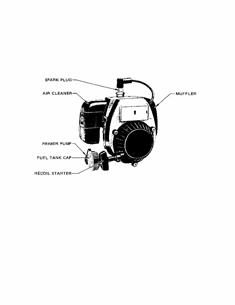
SPARK PLUG
AIR CLEANER
PRIMER PUMP
IEL TANK CAP
MUFFLER
RECOIL STARTER-
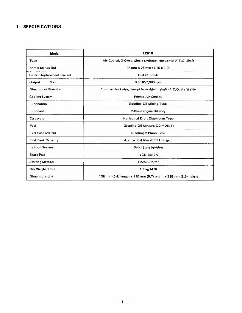
1. SPECIFICATIONS
Model ECOl R
Air-Cooled, 2-Cycle, Single Cylinder, Horizontal P.T.O. Shaft
Bore x Stroke (in)
Piston Displacement (cu. in)
Output Max.
15.4 cc (0.94)
0.6 HP17.000 rpm
Direction of Rotation
Forced Air Cooling Cooling System
Counter-clockwise, viewed from driving shaft (P.T.O. shaft) side
Lubrication I Gasoline-Oil Mixing Type
Lubricant 2-Cycle engine Oil only
Carburetor I Horizontal Draft Diaphragm Type
Fuel Gasoline-Oil Mixture (20 - 25: 1)
Fuel Feed System
Approx. 0.4 liter (0.1 1 U.S. gal.) Fuel Tank Capacity
Diaphragm Pump Type
Ignition System I Solid State Ignition
Spark Plug
Recoil Starter Starting Method
NGK BM-7A
Dry Weight (Ibs.) I 1.8 kg (4.0)
Dimensions (in) 1 3 8 m m (5.4) length x 170 mm (6.7) width x 225 mm (8.9) height
- 1 -
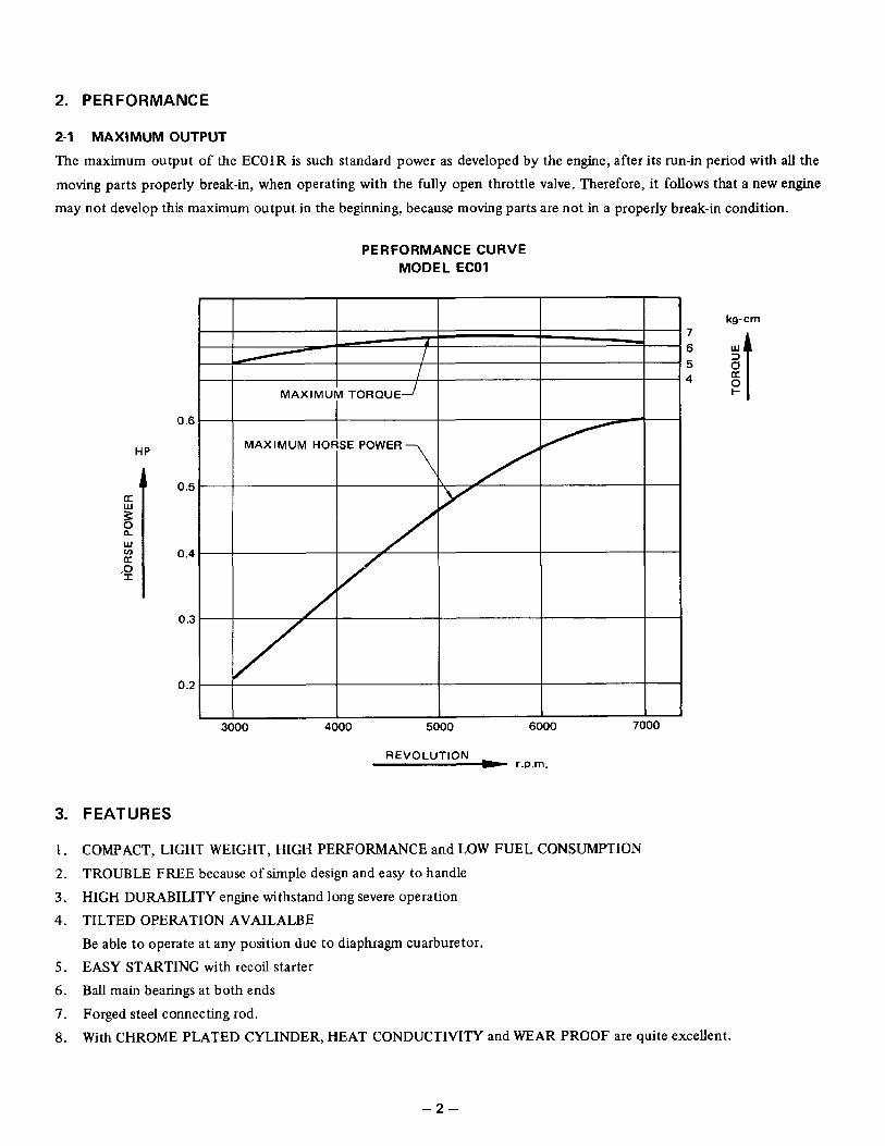
2. PERFORMANCE ,-
2-1 MAXIMUM OUTPUT
The maximum output of the ECOlR is such standard power as developed by the engine, after its run-in period with all the moving parts properly break-in, when operating with the fully open throttle valve. Therefore, it follows that a new engine may not develop this maximum output in the beginning, because moving parts are not in a properly break-in condition.
PERFORMANCE CURVE MODEL ECOl
3.
1.
2.
3.
4.
5.
6 .
7.
a.
I
I I I I I
MAXIMUM TORQUE--/ I
0.5
0.4
0.3
0.2
3000 4000 5000
REVOLUTION r.p.rn.
FEATURES
kg-crn 7
5 4 0
COMPACT, LIGHT WEIGHT, HIGH PERFORMANCE and LOW FUEL CONSUMPTION TROUBLE FREE because of simple design and easy to handle HIGH DURABILITY engine withstand long severe operation TILTED OPERATION AVAILALBE Be able to operate at any position due to diaphragm cuarburetor. EASY STARTING with recoil starter B d main bearings at both ends
Forged steel connecting rod. With CHROME PLATED CYLINDER, HEAT CONDUCTIVITY and WEAR PROOF are quite excellent.
,
4. DISASSEMBLY and REASSEMBLY
PREPARATION and SUGGESTIONS
When disassembling the engine, memorize the locations of individual parts so as to be able to reassemble them correct-
ly. Tag parts if there is a possibility of confusion. Prepare several boxes to keep parts belonging to certain groups together. Group those parts related each other, tentatively assembling where they belong, immediately after removing, in order
to prevent missing and misplacing.
Handle the disassembled parts carefully and wash them in kerosene.
Use the correct tools in the correct way. Standard tools required for disassembling and reassembling: a. Work table b. Washing pan c. Disassembling tools d. Washing oil (kerosene or gasoline), 2 cycle-oil e. Emery paper, cloth Before starting to disassemble the engine, drain fuel.
Tighten the screws of the cylinder, crankcase, connecting rod, spark plug, and flywheel to the specified torque values. Use new packings and gaskets in reassembly. Immediately before assembling parts, wash them in fresh gasoline or kerosene and blow them dry. Apply 2 cycle-oil on rotating and sliding parts.
Take care not to contaminate the parts by dust during assembling.
Tighten bolts, nuts and screws with proper torque according to their sizes. If small screws are tightened too tight, they may get broken. After completely assembling the engine, turn it by hand and check if there is any abnormality or loose members.
-3-
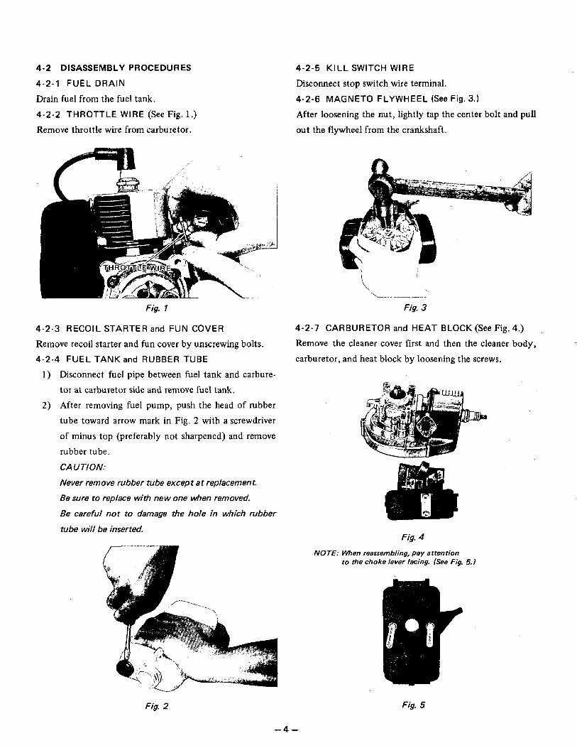
4-2 DISASSEMBLY PROCEDURES
4-2-1 FUEL DRAIN
Drain fuel from the fuel tank. 4-2-2 THROTTLE WIRE (See Fig. 1.) Remove throttle wire from carburetor.
Fig. 1
4-2 -3 RECOIL STARTER and FUN COVER
Remove recoil starter and fun cover by unscrewing bolts. 4-2-4 FUEL TANK and RUBBER TUBE
1) Disconnect fuel pipe between fuel tank and carbure- tor at carburetor side and remove fuel tank.
2) After removing fuel pump, push the head of rubber
tube toward arrow mark in Fig. 2 with a screwdriver of minus top @referably not sharpened) and remove rubber tube. CAUTION:
Never remove rubber tube except at replacement.
Be sure to replace with new one when removed.
Be careful not to damage the hole in which rubber
tube will be inserted.
4-2-5 KILL SWITCH WIRE
Disconnect stop switch wire terminal. 4-2-6 MAGNETO FLYWHEEL (See Fig. 3.)
After loosening the nut, Iightly tap the center bolt and pull out the flywheel from the crankshaft.
i I
Fig. 3
4-2-7 CARBURETOR and HEAT BLOCK (See Fig. 4.)
Remove the cleaner cover first and then the cleaner body,
carburetor, and heat block by loosening the screws. /"
Fig. 4
NOTE: When reassembling, pay attention to the choke lever facing. (See Fig. 5.)
,
Fig. 2
- 4 -
Fig. 5
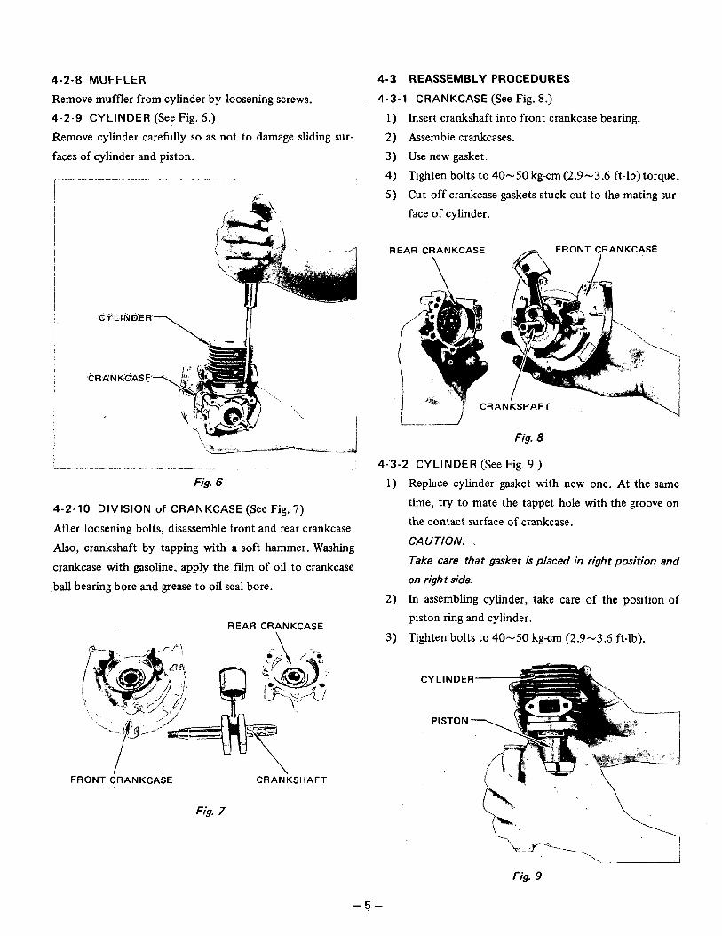
4-2-8 MUFFLER
Remove muffler from cylinder by loosening screws. 4-2-9 CYLINDER (See Fig. 6 . ) Remove cylinder carefully so as not to damage sliding sur- faces of cylinder and piston.
I
j L.-
,- I
4-2-10 DIVISION of CRANKCASE (See Fig, 7)
After loosening bolts, disassemble front and rear crankcase.
Also, crankshaft by tapping with a soft hammer. Washing crankcase with gasoline, apply the film of oil to crankcase
ball bearing bore and grease to oil seal bore.
REAR CRANKCASE
FRONT CRANKCASE CRANKSHAFT
Fig. 7
4-3 REASSEMBLY PROCEDURES
4-3-1 CRANKCASE (See Fig. 8.)
1) Insert crankshaft into front crankcase bearing. 2) Assemble crankcases. 3) Use new gasket. 4) Tighten bolts to 40-50 kg-cm(2.9-3.6 ft-1b)torque. 5) Cut off crankcase gaskets stuck out to the mating sur-
face of cylinder.
REAR CRANKCASE - FRONT CRANKCASE
Fig. 8
4-3-2 CYLINDER (See Fig. 9.) Replace cylinder gasket with new one. At the same time, try to mate the tappet hole with the groove on the contact surface of crankcase, CAUTION: ,
Take care that gasket is placed in right position and
on right side.
In assembling cylinder, take care of the position of piston ring and cylinder.
Tighten bolts to 40-50 kg-cm (2.9-3.6 ft-lb).
-5-
4-3-3 CARBURETOR and HEAT BLOCK
1) Use new gasket. 2) Tighten bolts to 40-50 kg-cm (2.9-3.6 ft-lb).
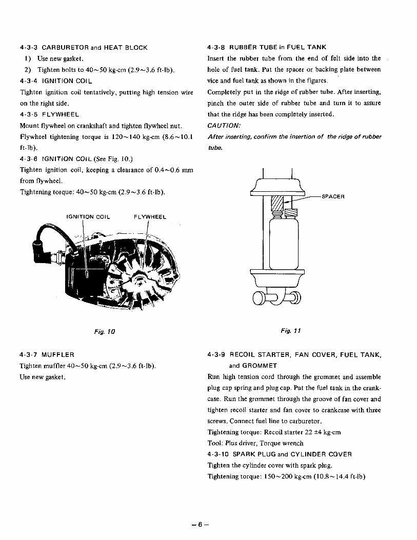
4-3-4 IGNITION COIL
Tighten ignition coil tentatively, putting high tension wire on the right side. 4-3 -5 FLYWHEEL
Mount flywheel on crankshaft and tighten flywheel nut. Flywheel tightening torque is 120-140 kg-cm (8.6-10.1 ft- lb). 4-3-6 IGNITION COIL (See Fig. 10.)
Tighten ignition coil, keeping a clearance of 0.4-0.6 mm from flywheel.
Tightening torque: 40-50 kg-cm (2.9-3.6 ft-lb).
4-3 -8 RUBBER TUBE in FUEL TANK
Insert the rubber tube from the end of felt side into the hole of fuel tank. Put the spacer or backing plate between
vice and fuel tank as shown in the figures.
Completely put in the ridge of rubber tube. After inserting, pinch the outer side of rubber tube and turn it to assure that the ridge has been completely inserted.
CAUTION:
After inserting, confirm the insertion of the ridge of rubber
tube.
,
IGNITION COIL FLYWHEEL
Fig. 10
4-3-7 MUFFLER
Tighten muffler 40-50 kg-cm (2.9-3.6 ft-lb). Use new gasket.
4-3 -9 RECOIL STARTER, FAN COVER, FUEL TANK,
and GROMMET
Run high tension cord through the grommet and assemble plug cap spring and plug cap. Put the fuel tank in the crank-
case. Run the grommet through the groove of fan cover and tighten recoil starter and fan cover to crankcase with three screws. Connect fuel line to carburetor. Tightening torque: Recoil starter 22 k4 kg-cm Tool: Plus driver, Torque wrench 4-3-10 SPARK PLUG and CYLINDER COVER
Tighten the cylinder cover with spark plug. Tightening torque: 150-200 kg-cm (10.8-14.4 ft-lb)
Fig. 1 1
,”
- 6 -
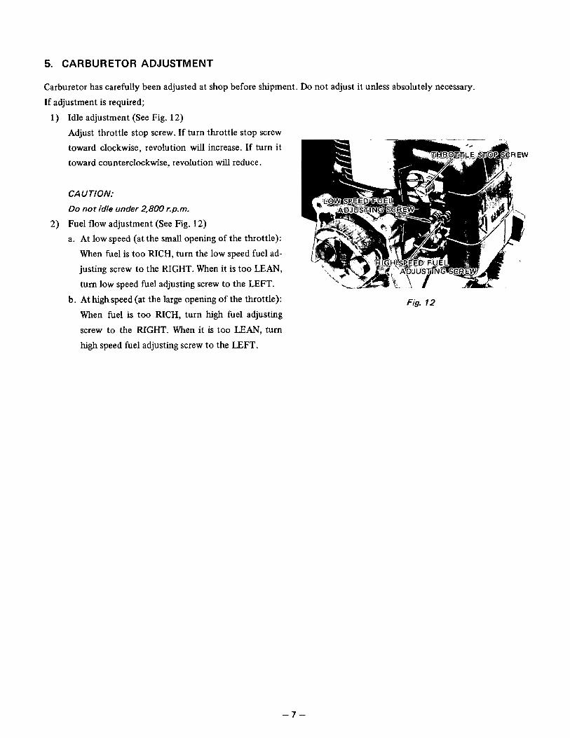
5. CARBURETOR ADJUSTMENT
Carburetor has carefully been adjusted at shop before shipment. Do not adjust it unless absolutely necessary.
If adjustment is required; Idle adjustment (See Fig. 12)
Adjust throttle stop screw. If turn throttle stop screw toward clockwise, revolution will increase. If turn it toward counterclockwise, revolution will reduce.
CAUTION:
Do not idle under 2,800 ?.p.m.
Fuel flow adjustment (See Fig. 12) a. At low speed (at the small opening of the throttle):
When fuel is too RICH, turn the low speed fuel ad- justing screw to the RIGHT. When it is too LEAN, turn low speed fuel adjusting screw to the LEFT.
b. At high speed (at the large opening of the throttle):
When fuel is too RICH, turn high fuel adjusting screw to the RIGHT. When it is too L E A N , turn
high speed fuel adjusting screw to the LEFT.
Fig. 12
- 7 -
6. OPERATION OF DIAPHRAGM CARBURETOR
When the engine runs, positive pressure and negative pressure will alternately occur in the crankcase. This alternation
in pressure is led to the reverse side of fuel pump diaphragm so that the top side will work as fuel pump. The fuel drawn up by fuel pump enters pressure compensating diaphragm chamber through the felt, rubber tube in fuel tank, fuel pipe and needle valve. The fuel in pressure compensating laphragm chamber is sent by pressure, so that the fuel pressure becomes higher
than atmospheric pressure and pushes down the pressure compensating diaphragm. When the pressure Compensating diaphragm is pushed downwards, the arm connected to needle valve turns by the
strength of spring and pushes up the needle valve, which shuts out the supply of fuel. The fuel in pressure compensating diaphragm chamber is measured by high speed fuel adjusting screw and low speed fuel adjusting screw, entering the engine through the carb venturi. Then, the pressure is present compensating dia- phragm chamber becomes lower than atmospheric pressure and the diaphragm is pushed up against the strength of spring. When the pressure compensating diaphragm is pushed up, the arm turns against the spring and lowers needle valve, which admits fuel to enter. After this, the same operation 1) - 6 ) are repeated.
NOTE: OPERATION OF TICKLER LEVER
When tickler lever is pushed down, the lever connected to needle valve turns against the strength of spring, lower-
ing needle valve, which allows fuel to enter.
In a condition of I ) , if primer pump is repeatedly pushed, fuel is pumped up from the tank and air in pressure
compensating diaphragm chamber is exhausted through the overflow valve, so that the pressure compensating
diaphragm chamber is filled with fuel.
Further, when primer pump is operated continuously, fuel is forced to flow into the overflow pipe through the
overflow valve and, at the same time, a little amount of fuel is sent to carb venturi through the high speed fuel ad-
justing screw and the low speed fuel adjusting screw.
A l i t t le amount of fuel sent to carb venturi by the operation of 31, if recoil starter is pulled, it is taken into the
engine, and becomes somewhat rich and suitable fuel for easy starting of the engine.
,-
- a -
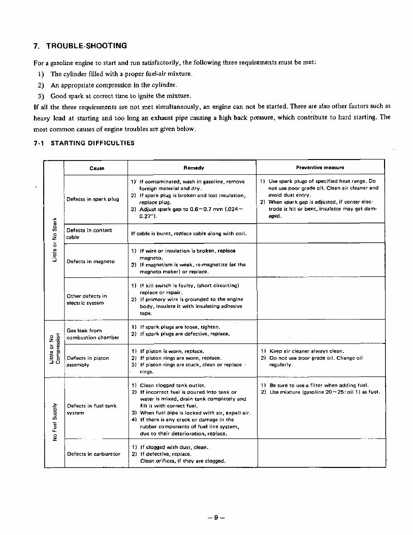
7. TROUBLE-SHOOTING
I For a gasoline engine to start and run satisfactorily, the following three requirements must be met: 1) The cylinder filled with a proper fuel-air mixture.
2) An appropriate compression in the cylinder. 3) Good spark at correct time to ignite the mixture.
If all the three requirements are not met simultaneously, an engine can not be started. There are also other factors such as
heavy load at starting and too long an exhaust pipe causing a high back pressure, which contribute to hard starting. The most common causes of engine troubles are given below.
7-1 STARTING DIFFICULTIES
Cause
Defects in spark plug
Defects in contact :able
Defects in magneto
Other defects in electric system
Gas leak from combustion chamber
Defects in piston assembly
Defects in fuel tank svstem
Defects in carburetor
Remedy
1 )' If contaminated, wash in gasoline, remove , foreign material and dry.
2) If spark plug is broken and lost insulation,
3) Adjust spark gap to 0.6-0.7 mm L024- replace plug.
0.27").
If cable is burnt, replace cable along with coil.
1) If wire or insulation is broken, replace
2) If magnetism is weak, re-magnetize (at the magneto.
magneto maker) or replace.
1) If kil l switch i s faulty, (short circuiting) replace or repair.
2) If primary wire is grounded to the engine body, insulate it with insulating adhesive tape.
1) If spark plugs are loose, tighten. 2) If spark plugs are defective, replace.
1) If piston is worn, replace. 2) If piston rings are worn, replace. 3) If piston rings are stuck, clean or replace
rings.
1) Clean clogged tank outlet. 2) If incorrect fuel is poured into tank or
water i s mixed, drain tank completely and fill it with correct fuel.
3) When fuel pipe i s locked with air, expel1 air. 4) If there is any crack or damage in the
rubber components of fuel line system, due to their deterioration, replace.
1 ) If clogged with dust, clean. 2) If defective, replace.
Clean orifices, if they are clogged.
Preventive measure
1 ) Use spark plugs of specified heat range. D o not use poor grade oi l . Clean air cleaner and avoid dust entry.
trode is hit or bent, insulator may get dam- aged.
2 ) When spark gap is adjusted, i f center elec-
1 ) Keep air cleaner always clean. 2) Do not use poor grade oil. Change oil
regularly.
1 ) Be sure to use a filter when adding fuel. 2) Use mixture (gasoline 20-25:o i l 1 ) as fuel.
- 9 -
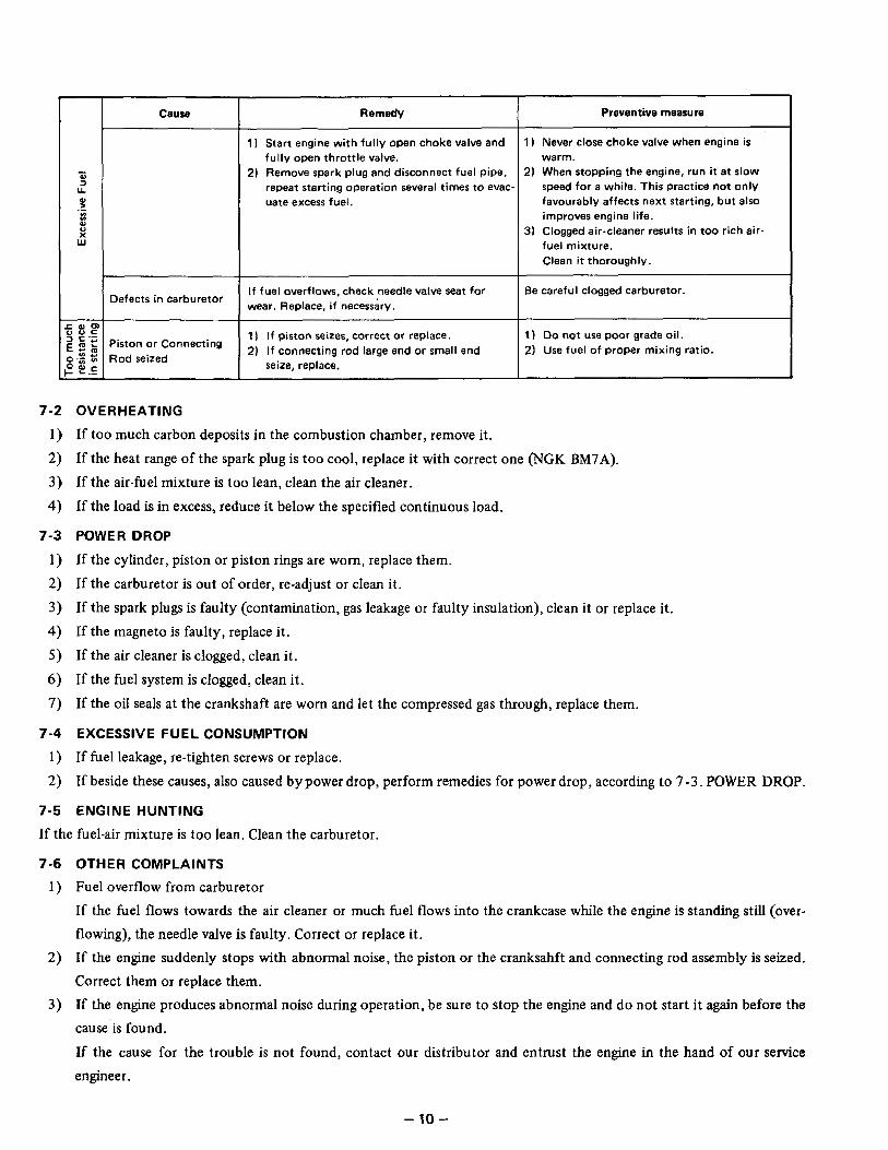
I Defects in carburetor
Remedy Preventive measure
1 ) Start engine with fully open choke valve and warm. fully open throttle valve.
1 ) Never close choke valve when engine is
2) Remove spark plug and disconnect fuel pipe, 2) When stopping the engine, run it at slow repeat starting operation several times t o evac- speed fo r a while. This practice not only uate excess fuel. favourably affects next starting, bu t also
improves engine life.
fuel mixture. Clean it thoroughly.
3) Clogged air-cleaner results in too r ich air-
If fuel overflows, check needle valve seat for wear. Replace, i f necessary.
Be careful clogged carburetor.
2) Use fuel of proper mixing ratio. 2) If connecting rod large end or small end 1 I Do not use poor grade oil. 1 ) I f piston seizes, correct or replace.
seize, replace.
7-2 OVERHEATING
1 ) If too much carbon deposits in the combustion chamber, remove it. 2) If the heat range of the spark plug is too cool, replace it with correct one (NGK BM7A).
3) If the air-fuel mixture is too lean, clean the air cleaner.
4) If the load is in excess, reduce it below the specified continuous load.
7-3 POWER DROP
1 ) If the cylinder, piston or piston rings are worn, replace them. 2) If the carburetor is out of order, re-adjust or clean it.
3) If the spark plugs is faulty (contamination, gas leakage or faulty insulation), clean it or replace it. 4) If the magneto is faulty, replace it.
5) If the air cleaner is clogged, clean it.
6 ) If the fuel system is clogged, clean it.
7) If the oil seals at the crankshaft are worn and let the compressed gas through, replace them.
7-4 EXCESSIVE FUEL CONSUMPTION
1) If fuel leakage, re-tighten screws or replace.
2) If beside these causes, also caused by power drop, perform remedies for power drop, according to 7 -3 . POWER DROP.
7-5 ENGINE HUNTING
If the fuel-air mixture is too lean. Clean the carburetor.
7 -6
1)
2)
3)
OTHER COMPLAINTS
Fuel overflow from carburetor If the fuel flows towards the air cleaner or much fuel flows into the crankcase while the engine is standing still (over- flowing), the needle valve is faulty. Correct or replace it. If the engine suddenly stops with abnormal noise, the piston or the cranksahft and connecting rod assembly is seized. Correct them or replace them. If the engine produces abnormal noise during operation, be sure to stop the engine and do not start it again before the ,
cause’is found.
If the cause for the trouble is not found, contact our distributor and entrust the engine in the hand of our service engineer.
- 10-
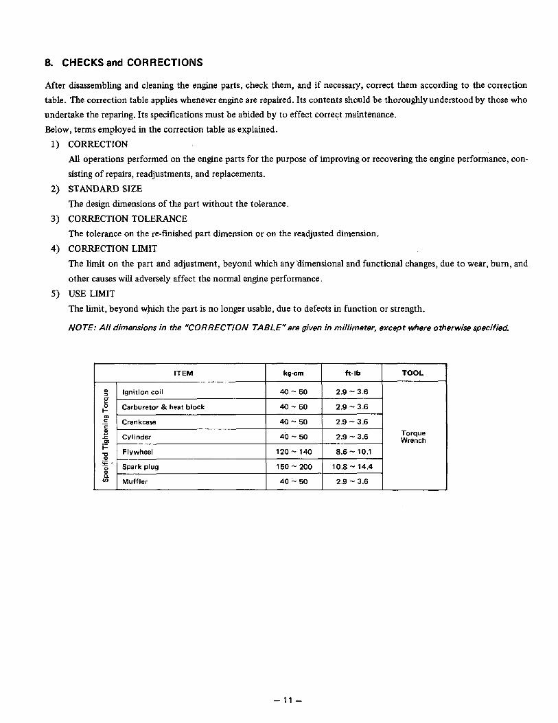
8. CHECKS and CORRECTIONS
After disassembling and cleaning the engine parts, check them, and if necessary, correct them according to the correction table. The correction table applies whenever engine are repaired. Its contents should be thoroughlyunderstood by those who undertake the reparing. Its specifications must be abided by to effect correct maintenance. Below, terms employed in the correction table as explained.
CORRECTION All operations performed on the engine parts for the purpose of improving or recovering the engine performance, con-
sisting of repairs, readjustments, and replacements. STANDARD SIZE The design dimensions of the part without the tolerance.
CORRECTION TOLERANCE The tolerance on the re-fmished part dimension or on the readjusted dimension.
CORRECTION LIMIT The limit on the part and adjustment, beyond which any 'dimensional and functional changes, due to wear, burn, and other causes will adversely affect the normal engine performance.
USE LIMIT
The limit, beyond whch the part is no longer usable, due to defects in function or strength.
NOTE: All dimensions in the "CORRECTION TABLE"are given in millimeter, except where otherwise specified.
ITEM TOOL ft- Ib kg-em
5
2.9 - 3.6 4b - 50 Cylinder 2
2.9 - 3.6 40 - 50 Crankcase .E
2.9 - 3.6 40 - 50 Carburetor 81 heat block
2.9 - 3.6 40 - 50 Ignition coil
Torque m Wrench F
Flywheel 120 - 140 8.6 - 10.1
.G Spark plug 150 - 200 10.8 -. 14.4
0 ) '
c a
01 .- "
a a Muffler 40 - 50 2.9 - 3.6
- 11 -
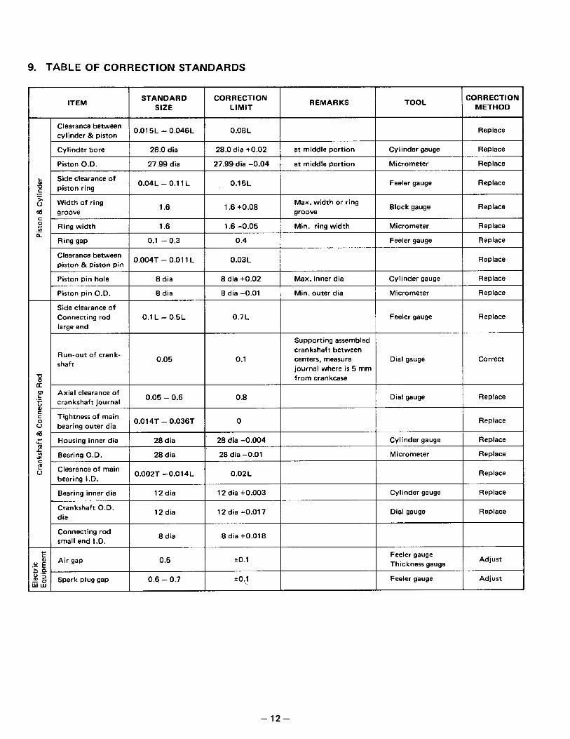
9. TABLE OF CORRECTION STANDARDS ,
T "+ REMARKS ITEM I STAl,SARD I CORRECTION LIMIT
SORRECTIOA METHOD
Replace
Replace
Replace
Replace
Replace
Replace
Replace
Replace
Replace
Replace
Replace
Correct
Replace
Replace
Replace
Replace
Replace
Replace
Replace
Adjust
Adjust
Clearance between cylinder & piston
0.01 5L - 0.046L 0.08 L
a t middle portion I Cylinder gauge Cylinder bore I 28.0 dia I 28.0 dia +0.02
Piston O.D. I 27.99 dia I 27.99 dia -0.04 at middle portion I Micrometer
Side clearance of piston ring
0.04L - 0.1 1 L I 0.15L Feeler gauge
I 1.6 +0.08 Max. width or r ing groove
Block gauge -
Min. ring width Micrometer
Feeler gauge
Ring width I 1.6 I 1.6 -0.05
Ring gap I 0.1 - 0.3 I 0.4
Clearance between piston & piston pin
0.004T - 0.01 1 L I 0.03L
Piston pin hole I 8 dia I 8 dia +0.02 Max. inner dia I Cylinder gauge
Piston pin O.D. I 8 dia I 8 dia -0.01 Min. outer dia I Micrometer
Feeler gauge Side clearance of Connecting rod 0.1 L - 0.5L
~~~~
Supporting assembled crankshaft between centers, measure journal where is 5 mm from crankcase
Dial gauge
Dial gauge Axial clearance of crankshaft journal
I 0.05 - 0.6 I 0.8
Tightness of main bearing outer dia
I 0.01 4T - 0.036T
Housing inner dia I 28 dia I 28 dia -0.004
Bearing O.D. I 28d ia 1 28 dia -0.01 Micrometer
Clearance of main bearing I.D.
0.002T -0.014L 1 0.02L I Cylinder gauge Bearing inner dia I 12 dia I 12 dia +0.003
Crankshaft O.D. dia
12 dia 12 dia -0.01 7 I Dial gauge
Connecting rod small end I.D. I 8 dia 8 dia +0.018
Feeler gauge Thickness gauge A i r gap 0.5 * O . l
Spark plug gap 0.6 - 0.7 *O .l I Feeler gauge
- 12-
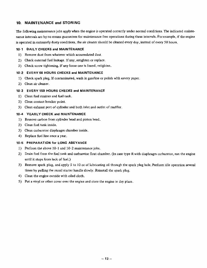
10. MAINTENANCE and STORING
The following maintenance jobs apply when the engine is operated correctly under normal conditions. The indicated mainte- nance intervals are by no means guarantees for maintenance free operations during these intervals. For example, if the engine is operated in extremely dusty conditions, the air cleaner should be cleaned every day, instead of every 50 hours.
10-1 DAILY CHECKS and MAINTENANCE
I
1) Remove dust from whatever which accumulated dust. 2) Check external fuel leakage. If any, retighten or replace. 3) Check screw tightening. If any loose one is found, retighten.
10-2 EVERY 50 HOURS CHECKS and MAINTENANCE
1) Check spark plug. If contaminated, wash in gasoline or polish with emery paper. 2) Clean air cleaner.
10-3 EVERY 150 HOURS CHECKS and MAINTENANCE
1) Clean fuel strainer and fuel tank. 2) Clean contact breaker point.
3) Clean exhaust port of cylinder and both inlet and outlet of muffler.
10-4 YEARLY CHECK and MAINTENANCE
1) Remove carbon from cylinder head and piston head. 2) Clean fuel tank inside. 3) Clean carburetor diaphragm chamber inside. 4) Replace fuel line once a year.
10-5 PREPARATION for LONG ABEYANCE
Perform the above 10- 1 and 10-2 maintenance jobs. Drain fuel from the fuel tank and carburetor float chamber. (In case type R with diaphragm carburetor, run the engine
until it stops from lack of fuel.) Remove spark plug, and apply 5 to 10 cc of lubricating oil through the spark plug hole. Perform idle operation several times by pulling the recoil starter handle slowly. Reinstall the spark plug.
Clean the engine outside with oiled cloth. Put a vinyl or other cover over the engine and store the engine in dry place.
- 13-
Industrial Engines