Boylestad Solutions Manual Electronic Devices and Circuits Th
Upload
kelsie-bylesCategory
view
213download
0
Robert BoylestadDigital Electronics
Copyright ©2002 by Pearson Education, Inc.Upper Saddle River, New Jersey 07458
All rights reserved.
Chapter 20: pnpn and Other Devices

Slide 1
Robert BoylestadDigital Electronics
Copyright ©2002 by Pearson Education, Inc.Upper Saddle River, New Jersey 07458
All rights reserved.
Part I: pnpn Devices
1. SCR – Silicon-Controlled Rectifier2. SCS – Silicon-Controlled Switch3. GTO – Gate Turn-Off Switch4. LASCR – Light-Activated SCR5. Shockley Diode6. Diac7. Triac

Slide 2
Robert BoylestadDigital Electronics
Copyright ©2002 by Pearson Education, Inc.Upper Saddle River, New Jersey 07458
All rights reserved.
1. SCR – Silicon-Controlled Rectifier
The SCR is a switching device for high voltage and current operations.
Schematic Symbol:

Slide 3
Robert BoylestadDigital Electronics
Copyright ©2002 by Pearson Education, Inc.Upper Saddle River, New Jersey 07458
All rights reserved.
SCR Basic OperationTurning - on
To turn the SCR on:1. forward bias the anode-cathode 2. apply sufficient gate voltage (Vgate) and Gate current (IGT)
Once the SCR is turned it remains latched on, even if the gate signal is removed. The SCR like a diode only conducts in one direction.
Slide 4
Robert BoylestadDigital Electronics
Copyright ©2002 by Pearson Education, Inc.Upper Saddle River, New Jersey 07458
All rights reserved.
SCR Basic OperationForced - on
An SCR can be forced on by
•Excessively high voltage from anode to cathode• High frequency signal from gate to cathode• High temperatures

Slide 5
Robert BoylestadDigital Electronics
Copyright ©2002 by Pearson Education, Inc.Upper Saddle River, New Jersey 07458
All rights reserved.
SCR Basic OperationTurning - off
Removing the gate voltage cannot turn off an SCR. It is latched on.
To turn the SCR off:• Remove the power source from anode to cathode• Reverse bias the anode-cathode
Both of the above can be accomplished with commutation circuitry.

Commutation circuitry is simply a switching device connected in parallel with the SCR.
A control signal activates the switching circuitry and provides a low impedance bypass for the anode to cathode current. This momentary loss of current through the SCR will turn it off.
The switching circuitry can also apply a reverse bias voltage across the SCR, which also will turn the SCR off.
Slide 6
Robert BoylestadDigital Electronics
Copyright ©2002 by Pearson Education, Inc.Upper Saddle River, New Jersey 07458
All rights reserved.
SCR Basic OperationCommutation

Slide 7
Robert BoylestadDigital Electronics
Copyright ©2002 by Pearson Education, Inc.Upper Saddle River, New Jersey 07458
All rights reserved.
SCR characteristics
The SCR has a characteristic horizontal voltage swing. The voltage across the SCR (VF) is high before it fires, but then it drops significantly once it begins conducting. The SCR only conducts in one direction.The SCR will “fire “ (turn on) if the voltage from anode to cathode is greater or equal to the forward breakover voltage (V(BR)F). In this instance the gate current (IG) can be 0.As more gate current is applied (IG1, IG2), less forward voltage (VF1, VF2, VF3) is required.Holding current (IH) is the minimum required current from anode to cathode.Reverse breakdown voltage is the maximum reverse bias voltage for the SCR.

Slide 8
Robert BoylestadDigital Electronics
Copyright ©2002 by Pearson Education, Inc.Upper Saddle River, New Jersey 07458
All rights reserved.
SCRs and Temperature
As temperature increases, the SCR requires less forward voltage and gate current to fire.
This means that at higher temperatures the SCR may fire by mistake!!

Slide 9
Robert BoylestadDigital Electronics
Copyright ©2002 by Pearson Education, Inc.Upper Saddle River, New Jersey 07458
All rights reserved.
SCR Terminal Identification
The SCR has three terminal Anode (A), Cathode (K), and the Gate (G).

Slide 10
Robert BoylestadDigital Electronics
Copyright ©2002 by Pearson Education, Inc.Upper Saddle River, New Jersey 07458
All rights reserved.
SCR Applications
The gate voltage can be set to fire the SCR at any point in the AC cycle. Remember the SCR is only a switch!
In this case the SCR fires as soon as the AC cycle crosses 0. Therefore it acts like a half-wave rectifier.

Slide 11
Robert BoylestadDigital Electronics
Copyright ©2002 by Pearson Education, Inc.Upper Saddle River, New Jersey 07458
All rights reserved.
SCR Applications (cont’d)
In this circuit, the SCR fires later in the cycle.
As you can see when the SCR fires provides more information than at what gate voltage.Therefore SCR firing is indicated by angle; i.e. at what degree in the AC cycle.In this circuit the SCR fires at 90, therefore it conducts for 90.The half-wave rectifier example fires at 0;therefore it conducts for 180.

Slide 12
Robert BoylestadDigital Electronics
Copyright ©2002 by Pearson Education, Inc.Upper Saddle River, New Jersey 07458
All rights reserved.
SCR Applications (cont’d)
• Battery-charging regulator• Temperature controller circuit• Emergency-lighting system
In these applications the SCR gate circuit is used to monitor a situation and trigger the SCR to turn on a portion of the circuit.

Slide 13
Robert BoylestadDigital Electronics
Copyright ©2002 by Pearson Education, Inc.Upper Saddle River, New Jersey 07458
All rights reserved.
2. SCS – Silicon-Controlled Switch
This device is like an SCR except that it has two gates: Cathode gate and an Anode gate.
Schematic Symbol:

Slide 14
Robert BoylestadDigital Electronics
Copyright ©2002 by Pearson Education, Inc.Upper Saddle River, New Jersey 07458
All rights reserved.
SCS Basic Operation
Either gate can fire the SCS. A positive pulse or voltage on the Cathode gate or a negative pulse or voltage on the Anode gate will fire the SCR. The SCS only conducts in one direction.The gates can also turn the SCS off. A negative pulse or voltage on the Cathode gate or a positive pulse or voltage on the Anode gate will fire the SCR.The difference between the gates: The Anode gate requires higher voltages than the Cathode gate.

Slide 15
Robert BoylestadDigital Electronics
Copyright ©2002 by Pearson Education, Inc.Upper Saddle River, New Jersey 07458
All rights reserved.
Comparison of SCR and SCS
The SCS has a much lower power capability compared to the SCR.
The SCS has faster switching times than the SCR.
The SCS can be switched off by gate control.

Slide 16
Robert BoylestadDigital Electronics
Copyright ©2002 by Pearson Education, Inc.Upper Saddle River, New Jersey 07458
All rights reserved.
SCS Applications
• Pulse generator• Voltage sensor• Alarm circuits

Slide 17
Robert BoylestadDigital Electronics
Copyright ©2002 by Pearson Education, Inc.Upper Saddle River, New Jersey 07458
All rights reserved.
SCS Pin Identification

Slide 18
Robert BoylestadDigital Electronics
Copyright ©2002 by Pearson Education, Inc.Upper Saddle River, New Jersey 07458
All rights reserved.
3. GTO – Gate Turn-Off Switch
GTO is similar to the SCR, except that the gate can turn the GTO on and off. It only conducts in one direction.
Schematic Symbol:

Slide 19
Robert BoylestadDigital Electronics
Copyright ©2002 by Pearson Education, Inc.Upper Saddle River, New Jersey 07458
All rights reserved.
Comparison of GTO and SCR
GTO is a low power device.
The gate signal necessary to fire the GTO is larger than the SCR gate signal.
The gate signal necessary to turn the GTO off is similar to that of SCS.
The switching rate for turning the GTO off is much faster than the SCR.
Slide 20
Robert BoylestadDigital Electronics
Copyright ©2002 by Pearson Education, Inc.Upper Saddle River, New Jersey 07458
All rights reserved.
GTO Applications
• Counters• Pulse generators• Oscillators• Voltage regulators

Slide 21
Robert BoylestadDigital Electronics
Copyright ©2002 by Pearson Education, Inc.Upper Saddle River, New Jersey 07458
All rights reserved.
GTO Pin Identification

Slide 22
Robert BoylestadDigital Electronics
Copyright ©2002 by Pearson Education, Inc.Upper Saddle River, New Jersey 07458
All rights reserved.
4. LASCR – Light-Activated SCR
This is an SCR that is fired by a light beam striking the gate to cathode junction or by applying a gate voltage.
Schematic Symbol:

Slide 23
Robert BoylestadDigital Electronics
Copyright ©2002 by Pearson Education, Inc.Upper Saddle River, New Jersey 07458
All rights reserved.
LASCR Pin Identification

Slide 24
Robert BoylestadDigital Electronics
Copyright ©2002 by Pearson Education, Inc.Upper Saddle River, New Jersey 07458
All rights reserved.
LASCR Applications
• Optical light controls• Relays• Phase control• Motor control• Computer applications
Slide 25
Robert BoylestadDigital Electronics
Copyright ©2002 by Pearson Education, Inc.Upper Saddle River, New Jersey 07458
All rights reserved.
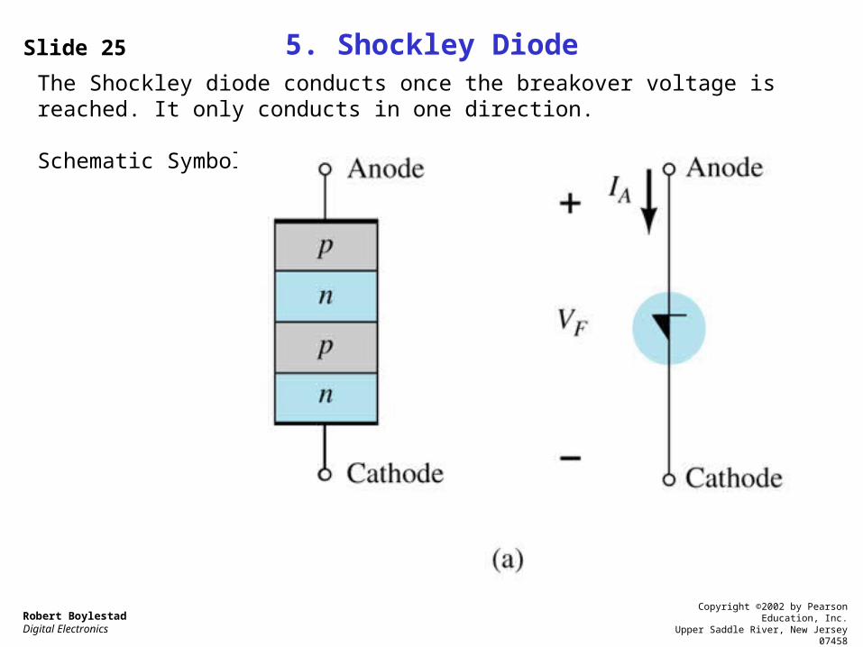
5. Shockley DiodeThe Shockley diode conducts once the breakover voltage is reached. It only conducts in one direction.
Schematic Symbol:

Slide 26
Robert BoylestadDigital Electronics
Copyright ©2002 by Pearson Education, Inc.Upper Saddle River, New Jersey 07458
All rights reserved.
Shockley Diode Basic Operation
The Shockley diode must be forward biased, and then once the voltage reaches the breakover level it will conduct. Like an SCR it only conducts in one direction.

Slide 27
Robert BoylestadDigital Electronics
Copyright ©2002 by Pearson Education, Inc.Upper Saddle River, New Jersey 07458
All rights reserved.
Shockley Diode Application
• Trigger switch for an SCR

Slide 28
Robert BoylestadDigital Electronics
Copyright ©2002 by Pearson Education, Inc.Upper Saddle River, New Jersey 07458
All rights reserved.
6. Diac
The Diac is also a breakover type device.
Schematic Symbol:
Slide 29
Robert BoylestadDigital Electronics
Copyright ©2002 by Pearson Education, Inc.Upper Saddle River, New Jersey 07458
All rights reserved.
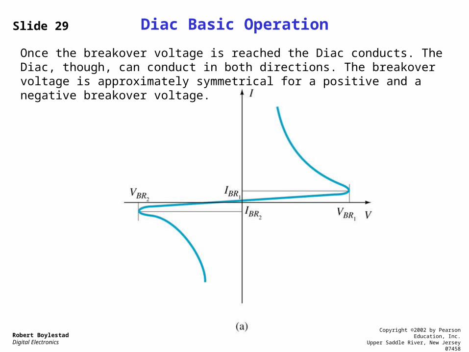
Diac Basic Operation
Once the breakover voltage is reached the Diac conducts. The Diac, though, can conduct in both directions. The breakover voltage is approximately symmetrical for a positive and a negative breakover voltage.

Slide 30
Robert BoylestadDigital Electronics
Copyright ©2002 by Pearson Education, Inc.Upper Saddle River, New Jersey 07458
All rights reserved.
Diac Applications
• Trigger circuit for the Triac• Proximity sensor circuit

Slide 31
Robert BoylestadDigital Electronics
Copyright ©2002 by Pearson Education, Inc.Upper Saddle River, New Jersey 07458
All rights reserved.
7. Triac
The Triac is like a Diac with a gate control.
Schematic Symbol:

Slide 32
Robert BoylestadDigital Electronics
Copyright ©2002 by Pearson Education, Inc.Upper Saddle River, New Jersey 07458
All rights reserved.
Triac Basic Operation
When fired by the gate or by exceeding the breakover voltage, the Triac conducts in both directions.

Slide 33
Robert BoylestadDigital Electronics
Copyright ©2002 by Pearson Education, Inc.Upper Saddle River, New Jersey 07458
All rights reserved.
Triac Pin Identification

Slide 34
Robert BoylestadDigital Electronics
Copyright ©2002 by Pearson Education, Inc.Upper Saddle River, New Jersey 07458
All rights reserved.
Triac Applications
AC power control circuits

Slide 35
Robert BoylestadDigital Electronics
Copyright ©2002 by Pearson Education, Inc.Upper Saddle River, New Jersey 07458
All rights reserved.
Part II: Other Devices
1. UJT – Unijunction Transistor2. Phototransistors3. Opto-Isolators4. PUT – Programmable UJT

Slide 36
Robert BoylestadDigital Electronics
Copyright ©2002 by Pearson Education, Inc.Upper Saddle River, New Jersey 07458
All rights reserved.
1. UJT – Unijunction Transistor
The UJT is also basically a switching device.
Schematic Symbol:

Slide 37
Robert BoylestadDigital Electronics
Copyright ©2002 by Pearson Education, Inc.Upper Saddle River, New Jersey 07458
All rights reserved.
UJT Basic Operation
Even though the UJT is a switching device it works very differently from the SCR variety of devices.
The equivalent circuit indicates that the UJT is like a diode and a resistive voltage divider circuit. The resistance exhibited by RB1 is variable; it is dependent on the value of current IE.

Slide 38
Robert BoylestadDigital Electronics
Copyright ©2002 by Pearson Education, Inc.Upper Saddle River, New Jersey 07458
All rights reserved.
UJT Characteristic Curve
A voltage is applied across the UJT (VBB) and to the Emitter input (VE). Once VE reaches a peak value (Vp) the UJT begins to conduct. At the point where VE = Vp, the current IE is at minimum. This is the threshold value of VE that puts the UJT into conduction. Once conducting, IE increases and VE decreases. This phenomenon occurs because the internal resistance labeled RB1 in the equivalent circuit decreases as the UJT conducts more and more. This is called negative resistance.

Slide 39
Robert BoylestadDigital Electronics
Copyright ©2002 by Pearson Education, Inc.Upper Saddle River, New Jersey 07458
All rights reserved.
UJT Characteristic Curves (cont’d)
As VBB increases so does the VE threshold voltage that is necessary to put the UJT into conduction.

Slide 40
Robert BoylestadDigital Electronics
Copyright ©2002 by Pearson Education, Inc.Upper Saddle River, New Jersey 07458
All rights reserved.
UJT Vp Voltage
The value of VE necessary to put the UJT into conduction is called Vp.
Vp can be calculated:
Vp = VBB
Where is the intrinsic stand-off ratio, and its value is available from the specification sheet of the UJT.

Slide 41
Robert BoylestadDigital Electronics
Copyright ©2002 by Pearson Education, Inc.Upper Saddle River, New Jersey 07458
All rights reserved.
UJT Pin Identification

Slide 42
Robert BoylestadDigital Electronics
Copyright ©2002 by Pearson Education, Inc.Upper Saddle River, New Jersey 07458
All rights reserved.
UJT Applications
The UJT is used almost exclusively as a trigger circuit for SCRs.

Slide 43
Robert BoylestadDigital Electronics
Copyright ©2002 by Pearson Education, Inc.Upper Saddle River, New Jersey 07458
All rights reserved.
UJT SCR Trigger Waveform
The UJT waveform to the SCR gate is almost a sawtooth like oscillator output. Hence this trigger circuit is sometimes called a relaxation oscillator. The rate at which the waveform repeats depends on the capacitor value, the external resistor, and .

Slide 44
Robert BoylestadDigital Electronics
Copyright ©2002 by Pearson Education, Inc.Upper Saddle River, New Jersey 07458
All rights reserved.
2. PhototransistorThis transistor is biased on by a light beam, which produces a base current. The greater the intensity of the light beam, the higher the resulting base and collector currents.It is sometimes called a photodetector.
Schematic Symbol:

Slide 45
Robert BoylestadDigital Electronics
Copyright ©2002 by Pearson Education, Inc.Upper Saddle River, New Jersey 07458
All rights reserved.
Phototransistor Pin Identification

Slide 46
Robert BoylestadDigital Electronics
Copyright ©2002 by Pearson Education, Inc.Upper Saddle River, New Jersey 07458
All rights reserved.
Phototransistor Applications
• Punch-card readers• Lighting control• Level indication• Relays• Counting system
Slide 47
Robert BoylestadDigital Electronics
Copyright ©2002 by Pearson Education, Inc.Upper Saddle River, New Jersey 07458
All rights reserved.
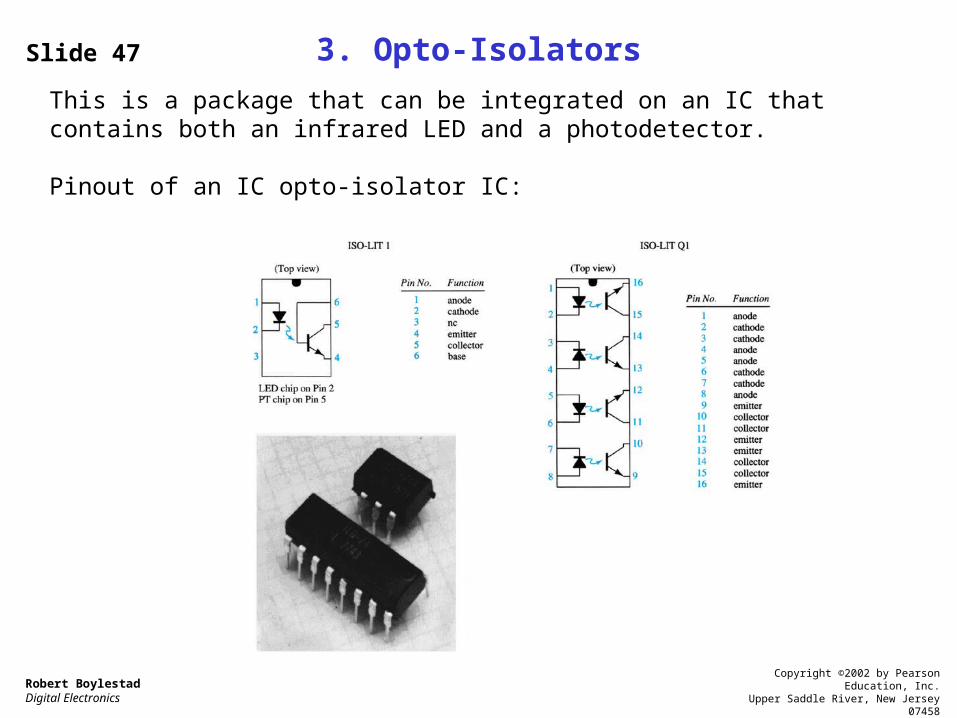
3. Opto-Isolators
This is a package that can be integrated on an IC that contains both an infrared LED and a photodetector.
Pinout of an IC opto-isolator IC:
Slide 48
Robert BoylestadDigital Electronics
Copyright ©2002 by Pearson Education, Inc.Upper Saddle River, New Jersey 07458
All rights reserved.
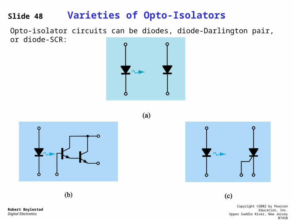
Varieties of Opto-Isolators
Opto-isolator circuits can be diodes, diode-Darlington pair, or diode-SCR:

Slide 49
Robert BoylestadDigital Electronics
Copyright ©2002 by Pearson Education, Inc.Upper Saddle River, New Jersey 07458
All rights reserved.
4. PUT – Programmable UJT
The PUT is more like an SCR in some of its operating characteristics, than a UJT.
Schematic Symbol:

Slide 50
Robert BoylestadDigital Electronics
Copyright ©2002 by Pearson Education, Inc.Upper Saddle River, New Jersey 07458
All rights reserved.
PUT Characteristics
Like the UJT, the PUT has a negative resistance region. But this region is unstable in the PUT. The PUT is operated between the on and off states.
Slide 51
Robert BoylestadDigital Electronics
Copyright ©2002 by Pearson Education, Inc.Upper Saddle River, New Jersey 07458
All rights reserved.
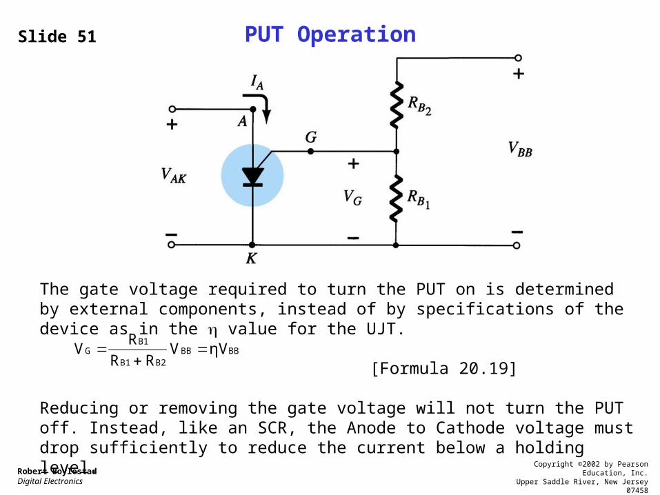
PUT Operation
The gate voltage required to turn the PUT on is determined by external components, instead of by specifications of the device as in the value for the UJT.
[Formula 20.19]
Reducing or removing the gate voltage will not turn the PUT off. Instead, like an SCR, the Anode to Cathode voltage must drop sufficiently to reduce the current below a holding level.
BBBBB2B1
B1G ηVV
RR
RV

Slide 52
Robert BoylestadDigital Electronics
Copyright ©2002 by Pearson Education, Inc.Upper Saddle River, New Jersey 07458
All rights reserved.
Applications of the PUT
The PUT is used as a trigger device for an SCR. Like the UJT, a relaxation oscillator circuit is used to trigger the PUT, which then fires the SCR.