ROADS AND MARITIME SERVICES (RMS) RMS … · 2.2 Fibre-reinforced Concrete ... A membrane...
28
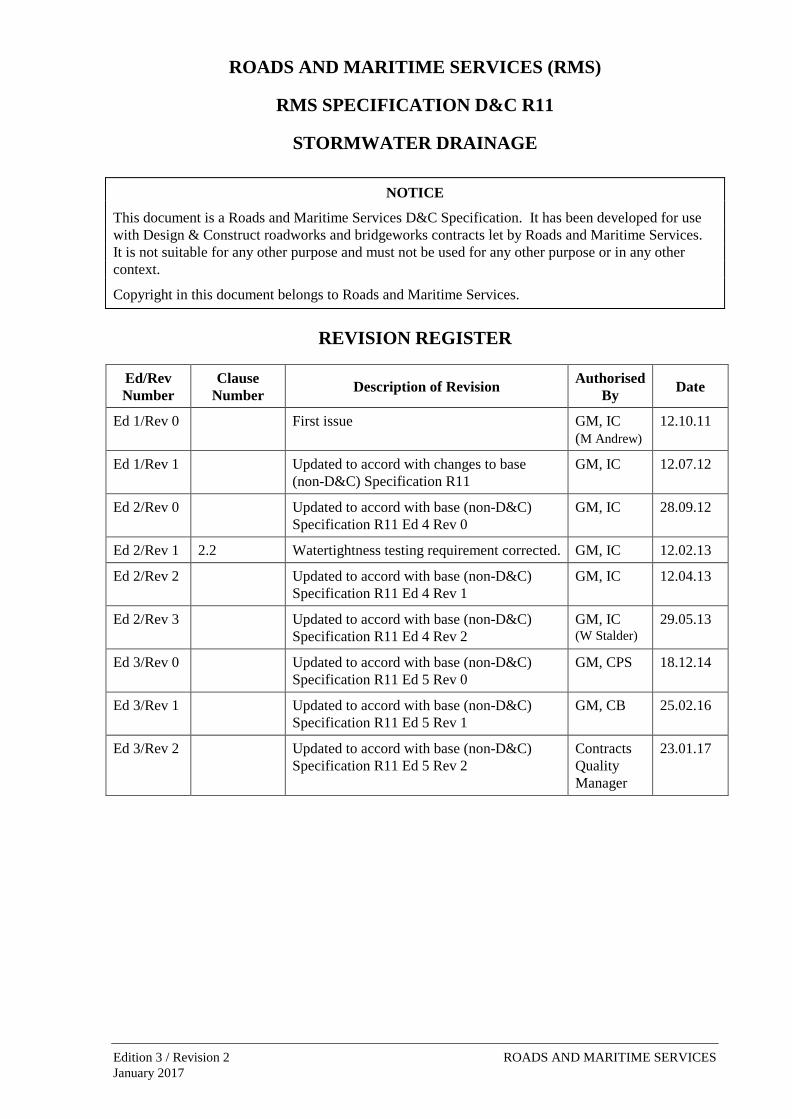
ROADS AND MARITIME SERVICES (RMS) RMS SPECIFICATION D&C R11 STORMWATER DRAINAGE NOTICE This document is a Roads and Maritime Services D&C Specification. It has been developed for use with Design & Construct roadworks and bridgeworks contracts let by Roads and Maritime Services. It is not suitable for any other purpose and must not be used for any other purpose or in any other context. Copyright in this document belongs to Roads and Maritime Services. REVISION REGISTER Ed/Rev Number Clause Number Description of Revision Authorised By Date Ed 1/Rev 0 First issue GM, IC (M Andrew) 12.10.11 Ed 1/Rev 1 Updated to accord with changes to base (non-D&C) Specification R11 GM, IC 12.07.12 Ed 2/Rev 0 Updated to accord with base (non-D&C) Specification R11 Ed 4 Rev 0 GM, IC 28.09.12 Ed 2/Rev 1 2.2 Watertightness testing requirement corrected. GM, IC 12.02.13 Ed 2/Rev 2 Updated to accord with base (non-D&C) Specification R11 Ed 4 Rev 1 GM, IC 12.04.13 Ed 2/Rev 3 Updated to accord with base (non-D&C) Specification R11 Ed 4 Rev 2 GM, IC (W Stalder) 29.05.13 Ed 3/Rev 0 Updated to accord with base (non-D&C) Specification R11 Ed 5 Rev 0 GM, CPS 18.12.14 Ed 3/Rev 1 Updated to accord with base (non-D&C) Specification R11 Ed 5 Rev 1 GM, CB 25.02.16 Ed 3/Rev 2 Updated to accord with base (non-D&C) Specification R11 Ed 5 Rev 2 Contracts Quality Manager 23.01.17 Edition 3 / Revision 2 ROADS AND MARITIME SERVICES January 2017
Transcript of ROADS AND MARITIME SERVICES (RMS) RMS … · 2.2 Fibre-reinforced Concrete ... A membrane...
ROADS AND MARITIME SERVICES (RMS)
RMS SPECIFICATION D&C R11
STORMWATER DRAINAGE
NOTICE
This document is a Roads and Maritime Services D&C Specification. It has been developed for use with Design & Construct roadworks and bridgeworks contracts let by Roads and Maritime Services. It is not suitable for any other purpose and must not be used for any other purpose or in any other context.
Copyright in this document belongs to Roads and Maritime Services.
REVISION REGISTER
Ed/Rev Number
Clause Number Description of Revision Authorised
By Date
Ed 1/Rev 0 First issue GM, IC (M Andrew)
12.10.11
Ed 1/Rev 1 Updated to accord with changes to base (non-D&C) Specification R11
GM, IC 12.07.12
Ed 2/Rev 0 Updated to accord with base (non-D&C) Specification R11 Ed 4 Rev 0
GM, IC 28.09.12
Ed 2/Rev 1 2.2 Watertightness testing requirement corrected. GM, IC 12.02.13
Ed 2/Rev 2 Updated to accord with base (non-D&C) Specification R11 Ed 4 Rev 1
GM, IC 12.04.13
Ed 2/Rev 3 Updated to accord with base (non-D&C) Specification R11 Ed 4 Rev 2
GM, IC (W Stalder)
29.05.13
Ed 3/Rev 0 Updated to accord with base (non-D&C) Specification R11 Ed 5 Rev 0
GM, CPS 18.12.14
Ed 3/Rev 1 Updated to accord with base (non-D&C) Specification R11 Ed 5 Rev 1
GM, CB 25.02.16
Ed 3/Rev 2 Updated to accord with base (non-D&C) Specification R11 Ed 5 Rev 2
Contracts Quality Manager
23.01.17
Edition 3 / Revision 2 ROADS AND MARITIME SERVICES January 2017

SPECIFICATION D&C R11
STORMWATER DRAINAGE Copyright – Roads and Maritime Services
IC-DC-R11
VERSION FOR: DATE:
Edition 3 / Revision 2 ROADS AND MARITIME SERVICES January 2017

Stormwater Drainage D&C R11
CONTENTS
CLAUSE PAGE
FOREWORD ............................................................................................................................................... II RMS Copyright and Use of this Document ................................................................................... ii Base Specification ......................................................................................................................... ii
1 GENERAL ........................................................................................................................................ 1 1.1 Scope .............................................................................................................................. 1 1.2 Structure of Specification ............................................................................................... 1 1.3 Definitions ...................................................................................................................... 2
2 MANUFACTURED DRAINAGE PRODUCTS ....................................................................................... 2 2.1 Precast Reinforced Concrete Pipes ................................................................................ 2 2.2 Fibre-reinforced Concrete Pipes ..................................................................................... 4 2.3 Precast Reinforced Concrete Box Culvert Units and Link Slabs ................................... 4 2.4 Other Precast Drainage Products .................................................................................... 4 2.5 Marking on Precast Units ............................................................................................... 6 2.6 Certificate of Conformity ............................................................................................... 7
3 SOIL AND GRAVEL MATERIALS ..................................................................................................... 7 3.1 Bedding and Support Fill Material ................................................................................. 7 3.2 Material Adjacent to Weepholes .................................................................................... 7 3.3 Fill Material for Embankments in Open Drains ............................................................. 8
4 CONSTRUCTION .............................................................................................................................. 8 4.1 General ........................................................................................................................... 8 4.2 Construction of Open Drains .......................................................................................... 8 4.3 Excavation for Drainage Structures ............................................................................. 10 4.4 Installation of Precast Concrete and Fibre-reinforced Concrete Pipe .......................... 11 4.5 Construction of Reinforced Concrete Box Culverts Using Precast Units .................... 12 4.6 Construction of Cast-in-place Reinforced Concrete Box Culverts .............................. 12 4.7 Construction of “Other Drainage Structures” .............................................................. 13 4.8 Weepholes .................................................................................................................... 14 4.9 Backfilling and Compaction ......................................................................................... 14 4.10 Disposal of Surplus Excavated Material ...................................................................... 16 4.11 Construction Traffic ..................................................................................................... 16
5 CONSTRUCTION TOLERANCES AND INSPECTION .......................................................................... 16 5.1 Construction Tolerances ............................................................................................... 16 5.2 Inspection ..................................................................................................................... 17
ANNEXURES R11/A TO R11/B – (NOT USED) ........................................................................................ 18
ANNEXURE R11/C – SCHEDULES OF HOLD POINTS, WITNESS POINTS AND IDENTIFIED RECORDS ....... 18 C1 Schedule of Hold Points and Witness Points ............................................................... 18 C2 Schedule of Identified Records .................................................................................... 18
ANNEXURE R11/D – PLANNING DOCUMENTS ........................................................................................ 19
ANNEXURES R11/E TO R11/K – (NOT USED) ........................................................................................ 19
ANNEXURE R11/L – MINIMUM FREQUENCY OF TESTING ..................................................................... 20
Ed 3 / Rev 2 i

D&C R11 Stormwater Drainage
ANNEXURE R11/M – REFERENCED DOCUMENTS................................................................................... 21
LAST PAGE OF THIS DOCUMENT IS .......................................................................................................... 22
FOREWORD
RMS COPYRIGHT AND USE OF THIS DOCUMENT
Copyright in this document belongs to Roads and Maritime Services.
When this document forms part of a deed
This document should be read with all the documents forming the Project Deed.
When this document does not form part of a deed
This copy is not a controlled document. Observe the Notice that appears on the first page of the copy controlled by RMS. A full copy of the latest version of the document is available on the RMS Internet website: http://www.rms.nsw.gov.au/business-industry/partners-suppliers/specifications/index.html
BASE SPECIFICATION
This document is based on Specification RMS R11 Edition 5 Revision 2.
ii Ed 3 / Rev 2

(RMS COPYRIGHT AND USE OF THIS DOCUMENT - Refer to the Foreword after the Table of Contents)
RMS SPECIFICATION D&C R11
STORMWATER DRAINAGE
1 GENERAL
1.1 SCOPE
This Specification sets out the requirements for construction of stormwater drainage systems, including the requirements for the supply of manufactured drainage products.
The requirements set out in this specification also applies to the construction of pedestrian and fauna crossings under roadways using box or pipe culverts.
1.2 STRUCTURE OF SPECIFICATION
This Specification includes a series of annexures that detail additional requirements.
1.2.1 (Not Used)
1.2.2 (Not Used)
1.2.3 Schedules of HOLD POINTS, WITNESS POINTS and Identified Records
The schedules in Annexure R11/C list the HOLD POINTS and WITNESS POINTS that must be observed. Refer to Specification RMS D&C Q6 for the definitions of HOLD POINTS and WITNESS POINTS.
The records listed in Annexure R11/C are Identified Records for the purposes of RMS D&C Q6 Annexure Q/E.
1.2.4 Planning Documents
The PROJECT QUALITY PLAN must include each of the documents and requirements shown in Annexure R11/D and must be implemented.
1.2.5 Minimum Frequency of Testing
The Inspection and Test Plan must nominate the proposed testing frequency to verify conformity of the item, which must not be less than the frequency specified in Annexure R11/L.
Where a minimum frequency is not specified, nominate an appropriate frequency.
Sampling and testing of materials and components, including placed fill, must comply with RMS D&C Q6.
1.2.6 Referenced Documents
Standards, specifications and test methods are referred to in abbreviated form (e.g. AS 1234). For convenience, the full titles are given in Annexure R11/M.
Ed 3 / Rev 2 1
(RMS COPYRIGHT AND USE OF THIS DOCUMENT - Refer to the Foreword after the Table of Contents)
D&C R11 Stormwater Drainage
1.3 DEFINITIONS
The terms “you” and “your” mean “the Contractor” and “the Contractor’s” respectively.
The following definitions are applicable to this Specification:
Contaminated material
Material classified as Restricted, Hazardous or Special Waste in accordance with EPA Waste Classification Guidelines.
Drainage structures
Devices to control stormwater flowing into and through a stormwater drainage system including culverts, inlet and outlet structures, junction boxes, gully pits, drop structures, headwalls, wingwalls, energy dissipators, and ancillary hardware such as grates, frames and step irons, as well as subsurface drainage pipes at pits, headwalls and wingwalls.
Geocomposite membrane
A membrane comprising a plastic permeable core enclosed in a geotextile.
Open drain An open channel constructed to intercept and redirect surface runoff water including catch drains, diversion drains, batter drains, inlet and outlet drains and diversion banks associated with stormwater drainage systems.
Inadequate Foundation Material
Material beneath or adjacent to the proposed drainage structure(s), which is deemed to be of insufficient strength to support the structure and loads on the structure, or material whose characteristics are deemed to adversely affect the performance or construction of the drainage structure.
Select Fill Fill material of specified quality placed against or adjacent to structures. This material is different from Selected Material.
Stormwater drainage system
One or more drainage structures and/or open drains arranged to collect and convey surface runoff water.
2 MANUFACTURED DRAINAGE PRODUCTS
2.1 PRECAST REINFORCED CONCRETE PIPES
The manufacturer must implement and maintain a Quality Management System in accordance with AS/NZS ISO 9001 as a means of ensuring that the manufactured precast concrete pipes conform to the requirements of the Specification.
Precast reinforced concrete pipes must comply with AS 4058 and the following requirements:
(I) Referring to Clause 6.1 of AS 4058, the following apply (the statements reproduced from AS 4058 are shown below in italics):
(a) Intended service requirements:
(i) Application: drainage.
(ii) Installation environment: normal, unless specified or shown otherwise on the Design Documentation drawings.
(b) Pipe size class or DN: as shown on the Design Documentation drawings.
2 Ed 3 / Rev 2

(RMS COPYRIGHT AND USE OF THIS DOCUMENT - Refer to the Foreword after the Table of Contents)
Stormwater Drainage D&C R11
(c) Pipe load class: as shown on the Design Documentation drawings.
(d) Pipe pressure or watertightness class:
(i) Non-pressure drainage pipes: (A) watertightness: only type testing is required, in accordance with AS 4058. (B) New Zealand application: not applicable. (C) nominated field test pressure: not applicable.
acceptance criteria: not applicable.
(ii) Pressure pipes: not applicable.
(e) Jacking loads: not applicable, unless pipe jacking is specified in the Design Documentation drawings.
(f) Pipe joint type: flexible, spigot and socket joint with rubber ring. Flush or butt joints must not be used.
(g) Confirm effective pipe length with supplier: not applicable.
(h) Elastomer type for elastomeric seal joints: must be natural rubber.
(i) Type tests and routine tests other than those “required” by Table 5.1 of AS 4058: not applicable.
(j) Means of demonstrating finished product compliance: in accordance with AS 4058.
(k) Place and rate of delivery: advise purchaser of place and rate of delivery.
(l) Place of acceptance: advise purchaser if other than the place of manufacture.
(m) Specific requirements for cement: cement must comply with Clause 2.2.1 of AS 4058.
(n) Type of admixtures: no variation from those permitted in Clause 2.2.5 of AS 4058.
(o) Other specific material requirements: other than the maximum chloride ion content specified in part II(c) of this clause, no variation from those permitted in Clauses 2.2 to 2.4 of AS 4058.
(p) Finishing and repair material specifications: no variation from those permitted by Clause 3.4.5 of AS 4058.
(q) Special pipe surface treatment or lining: not required, unless specified in the Design Documentation drawings.
(r) Marking requirements, if other than on the outside of the pipe: must be duplicated on the inside of the pipe, in accordance with Clause 2.5 of this Specification.
(II) In addition:
(a) the design diameter as defined in AS 4058 must not be less than 95% of the nominal size shown on the Design Documentation drawings for all classes of pipes up to and including Class 4;
(b) aggregates used in manufacture of reinforced concrete pipes must comply with Specification RMS D&C R53;
(c) the acid-soluble chloride ion content in concrete where steel reinforcement is present must not exceed 0.8 kg/m3 when tested in accordance with AS 1012.20.
Ed 3 / Rev 2 3

(RMS COPYRIGHT AND USE OF THIS DOCUMENT - Refer to the Foreword after the Table of Contents)
D&C R11 Stormwater Drainage
2.2 FIBRE-REINFORCED CONCRETE PIPES
The manufacturer must implement and maintain a Quality Management System in accordance with AS/NZS ISO 9001 as a means of ensuring that the manufactured precast concrete pipes conform to the requirements of the Specification.
Fibre-reinforced concrete pipes must comply with AS 4139 and the following requirements:
(I) Referring to Clause A1 in Appendix A of AS 4139, the following apply (the statements reproduced from AS 4139 are shown below in italics):
(a) Nominal pipe size: as shown on the Design Documentation drawings.
(b) Intended application: drainage.
(c) Pipe load class and installation conditions: as shown on the Design Documentation drawings.
(d) Type of joint: flexible, elastomeric, double V-ring joints, type (b)(i), as shown in Figure M1 in Appendix M of AS 4139. Elastomeric seals must comply with AS 1646. Butt joints must not be used.
(e) Tests other than those required by Clause 11.1 of AS 4139, “strength requirement”: not applicable.
(f) Any other special requirement: see (II) below.
(g) Specific requirements concerning repair of defects: not applicable. Pipes supplied with repaired defects must not be used in the Project Works.
(h) Statement of information supplied by manufacturer: provide to the Project Verifier, before commencement of delivery to the Site, all the information listed in Clause A2 of AS 4139 as well as the maximum recommended angular joint deflection.
(i) Place and rate of delivery: advise purchaser of place and rate of delivery.
(II) In addition:
(a) the internal diameter must not be less than 95% of the nominal size shown on the Design Documentation drawings for all classes of pipes.
2.3 PRECAST REINFORCED CONCRETE BOX CULVERT UNITS AND LINK SLABS
Design, testing, manufacture, and delivery to site of precast concrete box culvert units must be in accordance with Specification RMS D&C R16.
2.4 OTHER PRECAST DRAINAGE PRODUCTS
In Clause 2.4, references to “other drainage products” means drainage products other than precast reinforced concrete pipes, fibre-reinforced concrete pipes and precast reinforced concrete box culvert units and link slabs.
2.4.1 Design of “Other Drainage Products”
Where the supplier of the drainage product is responsible for its design, the design must be in accordance with the Standards shown in Table R11.1 for the particular type of structure or component.
4 Ed 3 / Rev 2

(RMS COPYRIGHT AND USE OF THIS DOCUMENT - Refer to the Foreword after the Table of Contents)
Stormwater Drainage D&C R11
Table R11.1 - Design Standards for “Other Drainage Products”
Item Description Standard
1 Members subject to traffic and/or earth pressure loading (1) AS 5100
2 Concrete water retaining structures:
(a) capacity > 25,000 litre (1) AS 3735
(b) capacity ≤ 25,000 litre AS 3600
3 Other concrete components AS 3600
4 Other non-concrete components appropriate AS
Notes: (1) Design and development must also comply with Specification RMS Q6 Clause 7.3.
Provide as part of the Quality Records the following:
(a) product drawings, including full dimensions of the product, reinforcement details, cover (if reinforced concrete), recommended attachment to adjoining structures and design lifting points, and certified by a structural engineer eligible for Corporate Membership of Engineers Australia and experienced in the design of structures;
(b) details of methods for manufacture, testing and installation including where applicable, clearance to pit shaft ends, pipe to pit jointing, headwall to cast-in-situ curtain wall structure attachment and step iron positioning.
A Hold Point applies to the supply of precast members subject to traffic and/or earth pressure loads, and concrete water retaining structures with capacity greater than 25,000 litres (items 1 and 2(a) in Table R11.1).
HOLD POINT
Process Held: Supply of precast concrete members subject to traffic and/or earth pressure loading, and water retaining structures with capacity greater than 25,000 litres.
Submission Details: At least 7 days prior to the date of delivery, submit the documents specified in Clause 2.4.1.
Release of Hold Point: The Nominated Authority will consider the documents and may audit the Quality Records prior to authorising the release of the Hold Point.
Where any of the above documents have been submitted previously, not more than 36 months prior to their intended use, in lieu of re-submission of the documents, you may advise the Project Verifier of the previous submission, and certify their applicability to this Deed.
2.4.2 Manufacture of “Other Drainage Products”
Manufacture of precast concrete members must be in accordance with Specification RMS D&C B115, except that the concrete used must comply with Specification RMS D&C R53 instead of RMS D&C B80.
Ed 3 / Rev 2 5

(RMS COPYRIGHT AND USE OF THIS DOCUMENT - Refer to the Foreword after the Table of Contents)
D&C R11 Stormwater Drainage
The acid-soluble chloride ion content in concrete where steel reinforcement is present must not exceed 0.8 kg/m3 when tested in accordance with AS 1012.20.
2.4.3 Precast Concrete Pits
If precast units are proposed for use to construct drainage pits, the base units (or any other riser units to which incoming drainage pipes will be joined) must be manufactured specifically to suit the design configuration of the particular pit with pre-formed knockouts only in the walls that require them. Standard precast pit base units with thinned wall sections on all four sides are not acceptable.
2.4.4 Access Covers and Grates
Metal access covers, grates and frames must comply with AS 3996. Covers and grates must not dislodge or rock in their frame when subjected to traffic loading. Covers and grates must be of the lift-out type, unless otherwise specified or shown on the Design Documentation drawings.
Access covers must be Load Class D, unsealed, solid-top or recessed with concrete infill, and manufactured from cast iron.
Grates and frames must be Load Class D, bicycle safe in all directions and manufactured from galvanised structural steel or ductile iron unless otherwise specified or shown on the Design Documentation drawings. Grates must include a fastening device which prevents their opening without the use of a tool.
Surface openings for grates in footpaths must comply with the requirements of AS 3996 for pedestrian areas.
2.4.5 Ladders and Step Irons
Ladders, including individual-rung ladders (step irons), must comply with AS 1657.
Ladders must be fabricated from steel, and hot-dip galvanized in accordance with AS/NZS 4680 after fabrication.
2.5 MARKING ON PRECAST UNITS
For all precast units with inner and outer surfaces, such as pipes or pits, markings must be made on both surfaces of the component.
For precast headwalls, markings must be made, as a minimum, on the side of the unit that will be exposed after installation.
Markings on the inside of pipes must, as a minimum, include the following:
(a) manufacturer’s name or registered mark;
(b) date of manufacture;
(c) pipe load class.
and may be painted on if located on the obvert of the pipe.
Markings for other precast units must include, in addition to items (a) and (b) above, the following:
(i) location of manufacture;
(ii) maximum mass of unit in kilograms;
6 Ed 3 / Rev 2

(RMS COPYRIGHT AND USE OF THIS DOCUMENT - Refer to the Foreword after the Table of Contents)
Stormwater Drainage D&C R11
(iii) any other identification necessary to directly relate the unit to tested samples, e.g. batch number;
(iv) inspection status.
2.6 CERTIFICATE OF CONFORMITY
Prior to incorporating into the Project Works any supplied manufactured drainage products, provide a signed certificate stating that the materials used and the finished product conform to the requirements of this Specification.
The certificate described above must describe the item and identify the inspection and test records that verify conformity of the item, and must be available for inspection as part of the Quality Records.
HOLD POINT
Process Held: Incorporation into the Works of any supplied manufactured drainage product.
Submission Details: Certificate of conformity, at least 7 days prior to incorporation into the Project Works.
Release of Hold Point: The Nominated Authority may inspect the Quality Records prior to authorising the release of the Hold Point.
3 SOIL AND GRAVEL MATERIALS
3.1 BEDDING AND SUPPORT FILL MATERIAL
3.1.1 Type BH Select Fill
Type BH Select Fill for Bed and Haunch zones must have the following properties:
(a) a particle size distribution, determined by Test Method RMS T201, within the limits set out in Table 6 in AS 3725 (or Table 5.1 in AS 1597.2); and
(b) a Plasticity Index, determined by Test Method RMS T109, of not more than 6.
3.1.2 Type SO Select Fill
Type SO Select Fill for Side and Overlay zones of pipes and box culverts and adjacent to other drainage structures must have the following properties:
(a) a maximum particle dimension of 53 mm; and
(b) a Plasticity Index, as determined by Test Method RMS T109, of between 2 and 12.
3.2 MATERIAL ADJACENT TO WEEPHOLES
Material placed adjacent to weepholes must be clean, graded, hard and durable crushed stone or river gravel conforming to the following requirements:
(a) maximum particle dimension of 53 mm; and
Ed 3 / Rev 2 7

(RMS COPYRIGHT AND USE OF THIS DOCUMENT - Refer to the Foreword after the Table of Contents)
D&C R11 Stormwater Drainage
(b) no more than 5% by mass passes the 9.5 mm AS sieve.
3.3 FILL MATERIAL FOR EMBANKMENTS IN OPEN DRAINS
Material for construction of embankments in open drains, such as diversion banks, must have:
(a) a particle size distribution, determined by RMS T107, such that between 20% and 60% inclusive by mass of material passes the 425 micron sieve; and
(b) a Plasticity Index, as determined by Test Method RMS T109, of between 15 and 30.
4 CONSTRUCTION
4.1 GENERAL
4.1.1 Setting Out
Set out the stormwater drainage systems as shown on the Design Documentation drawings in sufficient detail to identify:
(a) the locations, lengths and levels at outlets and inlets of pipes and box culvert structures;
(b) the locations and levels of gully pits, junction boxes, energy dissipators, and inlet and outlet structures;
(c) the locations and levels of the ends of wingwalls and headwalls; and
(d) the locations and levels of open drains.
HOLD POINT
Process Held: Construction of each drainage system.
Submission Details: Notification that set out of drainage system has been completed.
Release of Hold Point: The Nominated Authority will inspect the set out prior to authorising the release of the Hold Point.
Unless shown otherwise on the Design Documentation drawings, locate catch drains at a distance of not closer than 2.5 m from the top of the batter in cuttings, or the toe of batter in embankments.
4.1.2 Erosion and Sedimentation Control
For each part of a drainage system, complete the required erosion and sedimentation control measures prior to commencement of the drainage works (except those parts of the drainage system forming part of the control measures).
4.2 CONSTRUCTION OF OPEN DRAINS
4.2.1 Excavation of Open Drains
Excavate open drains (including topsoil) to the dimensions shown on the Design Documentation drawings.
8 Ed 3 / Rev 2

(RMS COPYRIGHT AND USE OF THIS DOCUMENT - Refer to the Foreword after the Table of Contents)
Stormwater Drainage D&C R11
Where dimensions are not shown, the open drain must have a minimum depth of 300 mm, a minimum waterway area of 0.2 m2, with side batter slopes not steeper than 2H:1V.
Grade the open drains to a slope of not less than 0.5% to ensure a free flow of water. Where this is not feasible, notify the Project Verifier.
HOLD POINT
Process Held: Construction of open drains with grade less than 0.5%.
Submission Details: Notification that 0.5% minimum grade cannot be achieved.
Release of Hold Point: The Nominated Authority will consider the matter, and will direct you further, prior to authorising the release of the Hold Point.
Extend open drains as necessary to natural drainage depressions or to a drainage system.
Trim open drains to produce a uniform surface free of irregularities. Compact the surfaces of drains to be lined to the requirements of Clause 4.9.2.
Deal with surplus materials from the construction of open drains in accordance with the requirements of Clause 4.9.3.
4.2.2 Embankments in Open Drains
Where construction of an embankment is required to form an open drain, clear, grub and strip of topsoil the affected area prior to placing the fill material. If inadequate foundation material is encountered, deal with the inadequate foundation material in accordance with the requirements of Clause 4.3.3.
Place fill material complying with Clause 3.3 in layers not exceeding 200 mm in depth, and compact to the requirements of Clause 4.9.2.
On completion of its construction, vegetate in accordance with Specification RMS D&C R178.
4.2.3 Lining
Unless otherwise shown on the Design Documentation drawings, line open drains with:
(a) organic fibre mat and vegetation, where the longitudinal grade of the completed drain is between 1% and 5% inclusive; or
(b) concrete where the longitudinal grade of the completed drain is less than 1% or greater than 5%.
Use rock mattresses only where shown on the Design Documentation drawings. Rock mattresses must comply with Specification RMS D&C R55.
Concrete lining must have a minimum compacted thickness of 100 mm measured at right angles to the surface of the lining, and must be colour matched with that of its surroundings.
Ed 3 / Rev 2 9

(RMS COPYRIGHT AND USE OF THIS DOCUMENT - Refer to the Foreword after the Table of Contents)
D&C R11 Stormwater Drainage
Install the type of lining in accordance with the following Specifications:
Type of Lining Specification
Cast-in-place concrete and sprayed concrete RMS D&C R53
Organic fibre mat RMS D&C R178
Wire mattresses RMS D&C R55
4.2.4 Movement Joints in Concrete Linings
Provide movement joints in concrete lining at intervals of not more than 3.0 m along the open drain to control cracking.
Movement joints must be straight narrow grooves, at 90° (± 5°) to the line of the drain, 20 (± 5) mm deep. Install expansion joint material complying with RMS D&C 3204 to the full depth of the concrete lining at every fifth movement joint.
4.3 EXCAVATION FOR DRAINAGE STRUCTURES
WITNESS POINT
Process: Excavation for pipe installation and other drainage structures.
Submission Details: Notification to the Nominated Authority, not later than 24 hours but not earlier than 5 working days, of the anticipated date of completion of excavation and preparation of foundations.
4.3.1 Excavation for Pipe Installation
Excavate trenches for pipe installation to the widths shown in RMS Model Drawing R0240 - 01 and AS 3725. Do not excavate more than 50 mm beyond the specified width of the trench for the part of the trench below the level of the top of the pipe, on either side of the trench, as this may affect the design pipe load class. (Refer to Model Drawing R0240 - 01.)
For pipes under embankments:
(i) where “Embankment Condition” installation is specified, construct first the embankment to a height of at least 0.7 times the external diameter of the pipe above the top of the bed zone, and for a minimum lateral distance past the boundary of the trench of 2.5 times the external diameter of the pipe;
(ii) where “Trench Condition” installation is specified, construct first the embankment to the level of the underside of the Selected Material Zone;
prior to excavating the trench and installation of the pipes.
Provide an alternative flow channel where appropriate.
4.3.2 Excavation for Drainage Structures Other Than Pipes
For drainage structures other than pipes, extend the excavation so that, for all points on the walls of the structure, the clear width between the structure wall and the face of the excavation is at least 300 mm.
10 Ed 3 / Rev 2
(RMS COPYRIGHT AND USE OF THIS DOCUMENT - Refer to the Foreword after the Table of Contents)
Stormwater Drainage D&C R11
When excavating for construction of box culverts and rock is encountered over part of the foundation, excavate the whole of the foundation area to a depth of 300 mm below the level of the bottom of the blinding layer and replace it with Type BH Select Fill, compacted to the requirements of Clause 4.9.2.
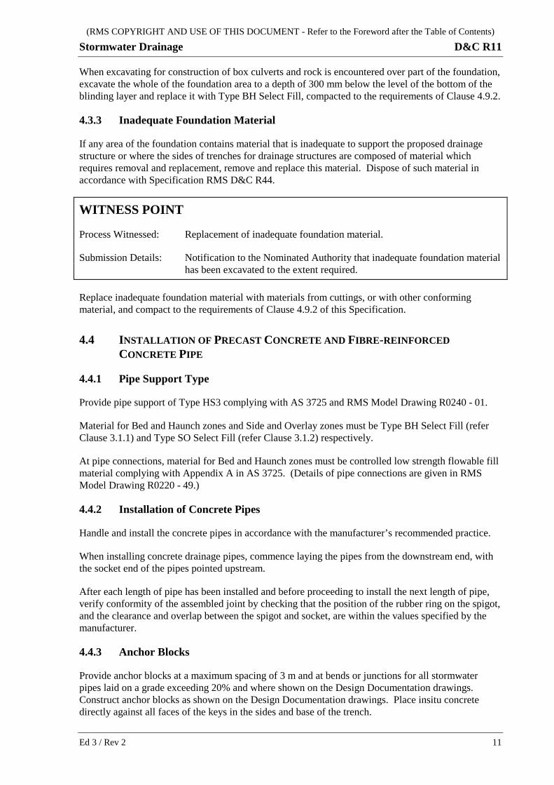
4.3.3 Inadequate Foundation Material
If any area of the foundation contains material that is inadequate to support the proposed drainage structure or where the sides of trenches for drainage structures are composed of material which requires removal and replacement, remove and replace this material. Dispose of such material in accordance with Specification RMS D&C R44.
WITNESS POINT
Process Witnessed: Replacement of inadequate foundation material.
Submission Details: Notification to the Nominated Authority that inadequate foundation material has been excavated to the extent required.
Replace inadequate foundation material with materials from cuttings, or with other conforming material, and compact to the requirements of Clause 4.9.2 of this Specification.
4.4 INSTALLATION OF PRECAST CONCRETE AND FIBRE-REINFORCED CONCRETE PIPE
4.4.1 Pipe Support Type
Provide pipe support of Type HS3 complying with AS 3725 and RMS Model Drawing R0240 - 01.
Material for Bed and Haunch zones and Side and Overlay zones must be Type BH Select Fill (refer Clause 3.1.1) and Type SO Select Fill (refer Clause 3.1.2) respectively.
At pipe connections, material for Bed and Haunch zones must be controlled low strength flowable fill material complying with Appendix A in AS 3725. (Details of pipe connections are given in RMS Model Drawing R0220 - 49.)
4.4.2 Installation of Concrete Pipes
Handle and install the concrete pipes in accordance with the manufacturer’s recommended practice.
When installing concrete drainage pipes, commence laying the pipes from the downstream end, with the socket end of the pipes pointed upstream.
After each length of pipe has been installed and before proceeding to install the next length of pipe, verify conformity of the assembled joint by checking that the position of the rubber ring on the spigot, and the clearance and overlap between the spigot and socket, are within the values specified by the manufacturer.
4.4.3 Anchor Blocks
Provide anchor blocks at a maximum spacing of 3 m and at bends or junctions for all stormwater pipes laid on a grade exceeding 20% and where shown on the Design Documentation drawings. Construct anchor blocks as shown on the Design Documentation drawings. Place insitu concrete directly against all faces of the keys in the sides and base of the trench.
Ed 3 / Rev 2 11

(RMS COPYRIGHT AND USE OF THIS DOCUMENT - Refer to the Foreword after the Table of Contents)
D&C R11 Stormwater Drainage
4.4.4 Sealing of Lifting Holes and Joints
Seal all lifting holes in the pipes, and all flush or butt joints used to extend existing pipes, to prevent the ingress of materials.
4.4.5 Subsurface Drainage Pipe at Discharge End of Pipes
Install a subsurface drainage pipe, complying with Specification RMS D&C 3552, at the discharge end of pipes at gully pits, junction boxes and headwalls unless the Design Documentation drawings specifically direct the subsurface drainage be omitted.
Unless otherwise shown on the Design Documentation drawings, the subsurface drainage pipe must be a 3 m length of 100 mm diameter subsoil pipe laid beside, and 100 mm above the invert level of the drainage pipe discharging through the wall of the pit or headwall. The subsoil pipe must be straight and discharge through the same wall as the drainage pipe. Seal the subsoil pipe at the upstream end and enclose it in a seamless tubular filter fabric complying with RMS D&C 3553.
4.5 CONSTRUCTION OF REINFORCED CONCRETE BOX CULVERTS USING PRECAST UNITS
4.5.1 Base Slab and Link Slab
Construct base slabs for the precast concrete box culvert units to the details shown on the Design Documentation drawings. Unless shown otherwise on the Design Documentation drawings, base slabs of box culverts using precast units must be cast-in-place reinforced concrete, cast on a blinding layer of 50 mm thick plain concrete.
Concrete work, including reinforcing steel and other embedded items, for base slabs and link slabs must comply with RMS D&C B80. Plain concrete for the blinding layer must comply with RMS D&C R53.
4.5.2 Installation of Precast Units
Install precast concrete crown units in accordance with the details shown on the Drawings. Where not shown on the Drawings, install them in accordance with Clause 5.4 of AS 1597.2.
4.5.3 Sealing and Finishing
After installation of the precast crown units, seal the transverse joint between adjacent units all round with a 250 mm wide, self-adhering membrane of rubberised asphalt integrally bonded to polypropylene mesh (e.g. Bituthene or approved equivalent), of minimum 1.6 mm thickness, unless shown otherwise on the Design Documentation drawings.
Seal lifting holes to prevent the ingress of materials. Cut off the protruding lifting hooks and coat the exposed steel with epoxy to prevent corrosion of the steel.
4.6 CONSTRUCTION OF CAST-IN-PLACE REINFORCED CONCRETE BOX CULVERTS
Construct cast-in-place reinforced box culverts in accordance with the Design Documentation drawings.
12 Ed 3 / Rev 2

(RMS COPYRIGHT AND USE OF THIS DOCUMENT - Refer to the Foreword after the Table of Contents)
Stormwater Drainage D&C R11
Concrete work, including reinforcing steel and other embedded items, for cast-in-place box culverts must comply with Specification RMS D&C B80.
4.7 CONSTRUCTION OF “OTHER DRAINAGE STRUCTURES”
In Clause 4.7, references to “other drainage structures” means “drainage structures other than pipes and box culverts”, and include gully pits, junction boxes, drop structures, inlet and outlet structures, headwalls, wingwalls and energy dissipators.
4.7.1 General
Construct “other drainage structures” in accordance with the Design Documentation drawings. Where precast units are used for the drainage structures, install the precast units in accordance with this Specification, RMS Model Drawings and the manufacturer’s recommendations.
Construct the “other drainage structures” as soon as possible and not later than 14 days after the installation of associated pipes, box culverts or open drains.
Concrete work for cast-in-place “other drainage structures” must comply with Specification RMS D&C R53, unless shown otherwise on the Design Documentation drawings.
4.7.2 Foundations for “Other Drainage Structures”
For precast pits, install the precast pit on top of a minimum 50 mm thick DGB20 bedding material, complying with Specification RMS D&C 3051, or controlled low strength flowable fill material complying with Appendix A in AS 3725, to support the precast pit uniformly.
For drainage structures other than precast drainage pits, provide a foundation of unreinforced concrete complying with Specification RMS D&C R53 not less than 50 mm thick, to uniformly support the structure unless shown otherwise on the Design Documentation drawings.
WITNESS POINT
Process Witnessed: Construction of drainage structures other than pipes and box culverts.
Submission Details: Notify the Nominated Authority at least 7 days prior to the date of commencement of the work.
4.7.3 Precast Headwalls
For precast headwalls for pipes of 300 mm to 1200 mm diameter, provide a curtain wall at the outer edge of the apron in accordance with the RMS Model Drawings. Do not use precast headwalls for pipes greater than 1200 mm diameter unless approved otherwise by the RMS Representative.
Do not use multi-piece modular precast headwalls unless approved otherwise by the RMS Representative.
4.7.4 Ladder
For all pits, such as junction box, gully pit, drop structure, etc, which are deeper than 600 mm, install an individual-rung ladder (step irons) in accordance with AS 1657 on one internal wall for the full depth of the structure.
Ed 3 / Rev 2 13

(RMS COPYRIGHT AND USE OF THIS DOCUMENT - Refer to the Foreword after the Table of Contents)
D&C R11 Stormwater Drainage
The top of the uppermost rung must not be more than 600 mm below the top of the pit. The top of the bottom rung must not be more than 500 mm or less than 300 mm above the invert of the pit. Rung spacings must be 300 mm ± 50 mm.
4.7.5 Isolation Joint
Install an isolation joint where a drainage structure will abut a structure or concrete pavement. The isolation joint must be 10 mm wide using preformed jointing filler complying with RMS D&C 3204.
4.8 WEEPHOLES
Where weepholes are provided in walls (whether retaining walls, headwalls, wingwalls or side wall of box culverts), place crushed stone or river gravel complying with Clause 3.2 in a continuous layer along the line of the weepholes and adjacent to the weepholes, on the fill side of the wall.
The gravel layer must extend to a height of not less than 450 mm vertically above the level of invert of the weepholes, and 300 mm horizontally into the fill.
Provide a geotextile complying with Specification RMS D&C R63 as separation between the gravel layer and the adjacent fill, with the geotextile wrapped over the top of the gravel layer.
Alternatively, subject to the RMS Representative’s concurrence, you may substitute the gravel layer with a geocomposite membrane of equivalent drainage capacity.
4.9 BACKFILLING AND COMPACTION
4.9.1 Backfilling
Backfill the Side and Overlay zones of box culverts (as shown in Figure 1.1 of AS 1597.2) with Type SO Select Fill.
For pipes and box culverts located within a rock fill embankment, provide a minimum thickness of 1000 mm of Type SO Select Fill within the Side and Overlay zones, separated from the surrounding rock fill by a geotextile complying with Specification RMS D&C R63.
Outside the Side and Overlay zones, backfill with general fill material excavated from cuttings or other suitable material.
Unless otherwise specified, place fill material for the foundations, bedding, support and general backfill in layers not exceeding 150 mm compacted thickness. Compact the fill material to the requirements of Clause 4.9.2 of this Specification.
Do not carry out backfilling against cast-in-place box culverts until the compressive strength of the concrete has reached at least 75% of the specified 28 day strength, and against other concrete drainage structures until at least 7 days has elapsed after placing the last concrete in the structure, unless accepted otherwise by the Project Verifier.
When backfilling against box culverts, the difference in level of the backfill on opposing sides of the culvert must not exceed 500 mm, to minimise differential loading on the structure. Compact first the fill placed immediately next to the structure, and then progressively work outwards towards the face of the excavation, to prevent wedge action between the excavation and the walls of the structure.
14 Ed 3 / Rev 2

(RMS COPYRIGHT AND USE OF THIS DOCUMENT - Refer to the Foreword after the Table of Contents)
Stormwater Drainage D&C R11
4.9.2 Compaction
Provide, as part of the PROJECT QUALITY PLAN, procedures for achieving adequate compaction of the Select Fill in Bed, Haunch, Side and Overlay zones around pipes in trenches.
Compact the foundations and fill material placed to achieve the minimum characteristic value of relative compaction for the particular type of material, as shown in Table R11.2.
Control the moisture content of the foundations and fill material to prevent loss of density and strength in nearby earthworks through over wetting.
Table R11.2 – Minimum Characteristic Value of Relative Compaction
Description of Material Min. Relative Compaction
Trimmed surface of excavated open drains to a depth of 150 mm, before placing lining or spreading topsoil for vegetation or fill material in embankments of open drains
95%
Material in trench base or foundation to a depth of 150 mm below the bottom of the Bed zone or blinding layer, and material replacing inadequate foundation material 95%
Select Fill in the Bed, Haunch, Side and Overlay zones adjacent to pipe culverts, and general backfill material 95%
Select Fill in the Side and Overlay zones of box culverts 98%
Backfill material within the Selected Material Zone of the adjoining earthworks (refer Specification RMS D&C R44) 102%
4.9.3 Determination of Field Density and Relative Compaction
Determine the field (insitu) density using either Test Methods RMS T173 using a nuclear gauge, RMS T119 using the sand replacement method, or RMS T165 using the fixed volume extractive method. The situations where these test methods are applicable are shown in Table R11.3.
Table R11.3 – Applicable Test Methods for Determining Field Density and Relative Compaction
Fill Material Properties Test Method / Actions
≤ 20% by mass retained on 37.5 mm AS sieve Either T173 (nuclear gauge) or T119 (sand replacement method)
> 20%, ≤ 40% by mass retained on 37.5 mm AS sieve T119 (sand replacement method) (1)
> 40% by mass retained on 37.5 mm AS sieve Report only % by mass of oversize material (2)
Fine to medium grained cohesionless materials, including one size material or gap graded material
T165 (fixed volume extractive method)
Notes: (1) If % by mass retained on 37.5 mm AS sieve is between 20% and 40%, do not use the nuclear gauge method. (2) If % by mass retained on 37.5 mm AS sieve is greater than 40%, do not report the relative compaction as the
test result obtained is not valid.
Do not use RMS T173 (nuclear gauge) for insitu density tests if the layer thickness exceeds 300 mm.
Ed 3 / Rev 2 15

(RMS COPYRIGHT AND USE OF THIS DOCUMENT - Refer to the Foreword after the Table of Contents)
D&C R11 Stormwater Drainage
Calculate the relative compaction using Test Method RMS T166.
Determine the characteristic value of relative compaction in accordance with Specification RMS D&C Q6. Round off the relative compaction value and the characteristic relative compaction value to the nearest 0.1%.
4.10 DISPOSAL OF SURPLUS EXCAVATED MATERIAL
Dispose of as spoil any surplus excavated material in accordance with Specification RMS D&C R44.
4.11 CONSTRUCTION TRAFFIC
Where you propose to move heavy construction plant and vehicles over pipe or box culvert structures, design and provide protective measures for each crossing in accordance with the Deed.
HOLD POINT
Process Held: Moving heavy construction plant or vehicles over pipe or box culvert structures.
Submission Details: Certificate and verification of protective measures.
Release of Hold Point: The Nominated Authority may examine the submitted documents, prior to authorising the release of the Hold Point.
5 CONSTRUCTION TOLERANCES AND INSPECTION
5.1 CONSTRUCTION TOLERANCES
Construct the stormwater drainage system so that water flows through the system without unintended ponding, and within the construction tolerances in Table R11.4:
Table R11.4 - Maximum Construction Tolerances
Component Attribute Tolerance
Concrete pipes, box culverts, headwalls and wingwalls, energy dissipators, inlet and outlet structures
Location (plan)
Within 200 mm of the plan position shown on the Design Documentation drawings or specified at any point
Invert level Within 20 mm of the design level at any point
Gully pits and junction boxes Location (plan)
Within 200 mm longitudinally and 20 mm laterally of the plan position, with reference to the control line for the road shown on the Design Documentation drawings
Outlet invert level
Within 20 mm of the invert level shown on the Design Documentation drawings
16 Ed 3 / Rev 2

(RMS COPYRIGHT AND USE OF THIS DOCUMENT - Refer to the Foreword after the Table of Contents)
Stormwater Drainage D&C R11
Component Attribute Tolerance
Lintels, covers and gratings Line The tolerances specified for the adjoining material; e.g. RMS D&C R15 for kerbs and gutters, RMS D&C R116 or RMS D&C R119 for asphalt and RMS D&C R83 for concrete base.
Precast concrete box culvert units
Step between units
On the internal faces of the walls and roof, no step between adjacent units must exceed 20 mm. Steps between 10 mm and 20 mm must be smoothed to a standard of durability equal to the rest of the culvert.
Open drains Location The tolerances specified for the adjoining material, including RMS D&C R44 for berm drains and batter drains
Level Within 50 mm of the design level at any point provided that there is a continuous downgrade in the direction of flow not less than 0.5% at any point
Waterway area
Not less than 95% of the design cross sectional area at any point
Shape Not more than a 50 mm departure from a 3 m straight edge placed on the bottom or a side of the open drain at any point
Trenches for precast concrete and fibre-reinforced concrete pipe drainage structures
When measured horizontally at any point within the trench at right angles to the line of the pipes:
Position of trench face:
Within 100 mm of the design location
Excavation width:
Not less than the specified width; Not more than the specified width plus 100 mm
5.2 INSPECTION
Carry out closed-circuit television (CCTV) inspections of all pipe and box culverts with dimensions that restrict human access, to verify that the works have been constructed within the specified tolerances, the flow of water is not obstructed by waste construction material left inside, and to check for visible signs of defects, at the following times:
(a) on completion of the subject drainage structure and prior to commencement of the overlying pavement, and
(b) no more than 14 days prior to Completion.
On completion of the inspections, submit to the Principal a report of these inspections and any nonconformity detected. Include any video recordings taken during the CCTV inspection.
The inspection and reporting must be accordance with WSA 05 – 2008.
Ed 3 / Rev 2 17
(RMS COPYRIGHT AND USE OF THIS DOCUMENT - Refer to the Foreword after the Table of Contents)
D&C R11 Stormwater Drainage
ANNEXURES R11/A TO R11/B – (NOT USED)
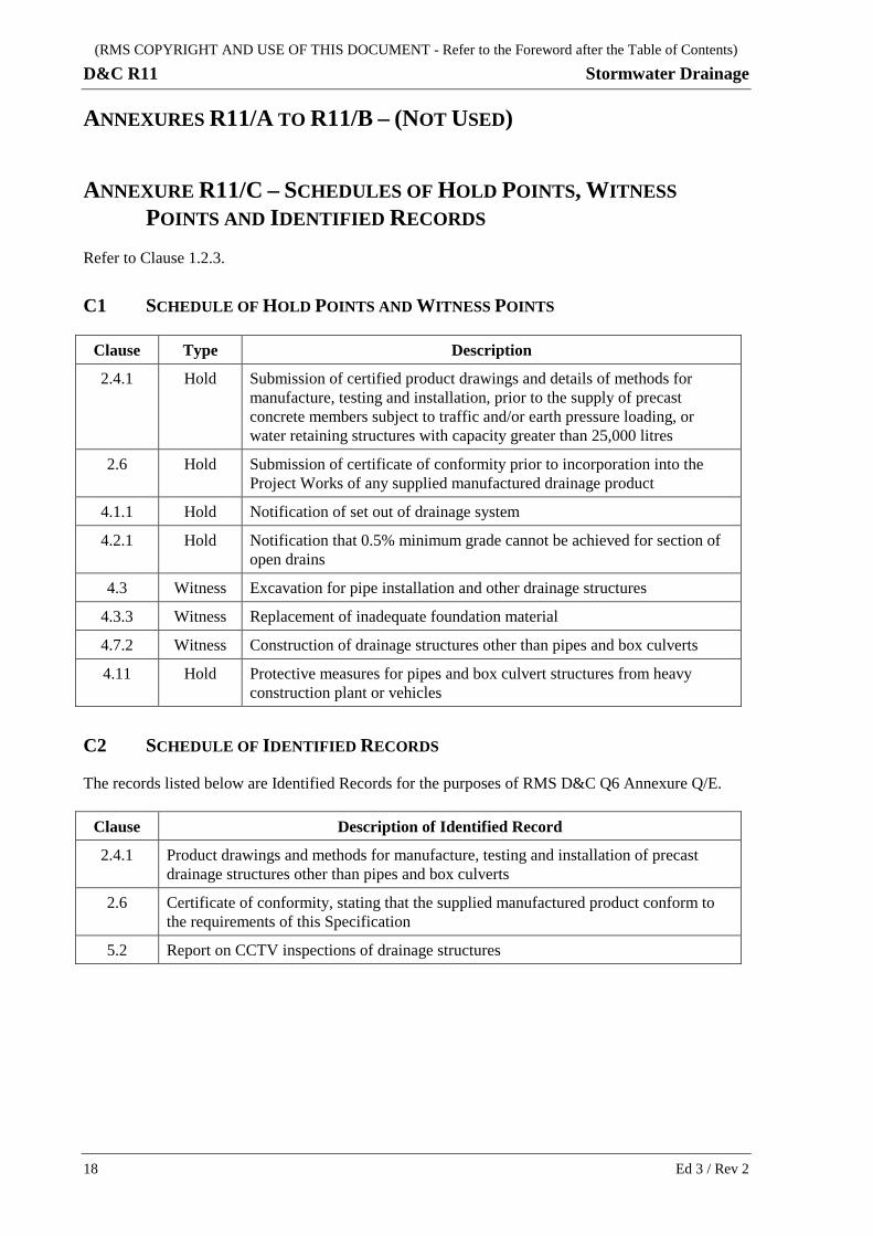
ANNEXURE R11/C – SCHEDULES OF HOLD POINTS, WITNESS POINTS AND IDENTIFIED RECORDS
Refer to Clause 1.2.3.
C1 SCHEDULE OF HOLD POINTS AND WITNESS POINTS
Clause Type Description
2.4.1 Hold Submission of certified product drawings and details of methods for manufacture, testing and installation, prior to the supply of precast concrete members subject to traffic and/or earth pressure loading, or water retaining structures with capacity greater than 25,000 litres
2.6 Hold Submission of certificate of conformity prior to incorporation into the Project Works of any supplied manufactured drainage product
4.1.1 Hold Notification of set out of drainage system
4.2.1 Hold Notification that 0.5% minimum grade cannot be achieved for section of open drains
4.3 Witness Excavation for pipe installation and other drainage structures
4.3.3 Witness Replacement of inadequate foundation material
4.7.2 Witness Construction of drainage structures other than pipes and box culverts
4.11 Hold Protective measures for pipes and box culvert structures from heavy construction plant or vehicles
C2 SCHEDULE OF IDENTIFIED RECORDS
The records listed below are Identified Records for the purposes of RMS D&C Q6 Annexure Q/E.
Clause Description of Identified Record
2.4.1 Product drawings and methods for manufacture, testing and installation of precast drainage structures other than pipes and box culverts
2.6 Certificate of conformity, stating that the supplied manufactured product conform to the requirements of this Specification
5.2 Report on CCTV inspections of drainage structures
18 Ed 3 / Rev 2

(RMS COPYRIGHT AND USE OF THIS DOCUMENT - Refer to the Foreword after the Table of Contents)
Stormwater Drainage D&C R11
ANNEXURE R11/D – PLANNING DOCUMENTS Refer to Clause 1.2.4.
The following documents are a summary of documents that must be included in the PROJECT QUALITY PLAN. The requirements of this Specification and others included in the deed must be reviewed to determine additional documentation requirements.
Clause Description
2.4 Detailed drawings and methods for manufacture, testing and installation of precast drainage structures other than pipes and box culverts.
2.6 Certificate of conformity that pipes, culverts, precast concrete units, access covers, road grates and frames, comply with the requirements of this Specification.
4.9.2 Procedures for achieving adequate compaction of Select Fill in Bed, Haunch, Side and Overlay zones around pipes in trenches.
ANNEXURES R11/E TO R11/K – (NOT USED)
Ed 3 / Rev 2 19

(RMS COPYRIGHT AND USE OF THIS DOCUMENT - Refer to the Foreword after the Table of Contents)
D&C R11 Stormwater Drainage
ANNEXURE R11/L – MINIMUM FREQUENCY OF TESTING Refer to Clause 1.2.5. Clause Characteristic Analysed Test Method Minimum Frequency of Testing
2.1 Precast concrete pipes: AS 4058 As specified in Clause 2.1 and AS 4058
2.2 Fibre reinforced concrete pipes: AS 4139 As specified in Clause 2.2 and AS 4139
3.1 Select Fill in Bed and Haunch zones:
Particle size distribution RMS T201 - One per 50 m3 or part thereof prior to placement
Plasticity Index RMS T109 - One per 100 m3 or part thereof prior to placement
3.1 Select Fill in Side and Overlay zones:
Particle size distribution RMS T201 - One per 100 m3 or part thereof prior to placement
Plasticity Index RMS T109 - One per 200 m3 or part thereof prior to placement
4.9.2 Compaction:
Surface of excavated open drains
Foundations and trench bases
Select Fill
General fill
Selected Material Zone
RMS T166 - In accordance with the
requirements of Specification RMS D&C Q6 Annexure L3
20 Ed 3 / Rev 2
(RMS COPYRIGHT AND USE OF THIS DOCUMENT - Refer to the Foreword after the Table of Contents)
Stormwater Drainage D&C R11
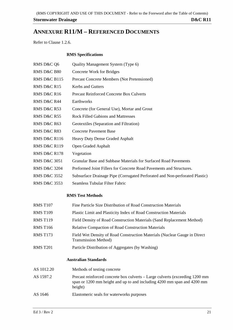
ANNEXURE R11/M – REFERENCED DOCUMENTS Refer to Clause 1.2.6.
RMS Specifications
RMS D&C Q6 Quality Management System (Type 6)
RMS D&C B80 Concrete Work for Bridges
RMS D&C B115 Precast Concrete Members (Not Pretensioned)
RMS D&C R15 Kerbs and Gutters
RMS D&C R16 Precast Reinforced Concrete Box Culverts
RMS D&C R44 Earthworks
RMS D&C R53 Concrete (for General Use), Mortar and Grout
RMS D&C R55 Rock Filled Gabions and Mattresses
RMS D&C R63 Geotextiles (Separation and Filtration)
RMS D&C R83 Concrete Pavement Base
RMS D&C R116 Heavy Duty Dense Graded Asphalt
RMS D&C R119 Open Graded Asphalt
RMS D&C R178 Vegetation
RMS D&C 3051 Granular Base and Subbase Materials for Surfaced Road Pavements
RMS D&C 3204 Preformed Joint Fillers for Concrete Road Pavements and Structures.
RMS D&C 3552 Subsurface Drainage Pipe (Corrugated Perforated and Non-perforated Plastic)
RMS D&C 3553 Seamless Tubular Filter Fabric
RMS Test Methods
RMS T107 Fine Particle Size Distribution of Road Construction Materials
RMS T109 Plastic Limit and Plasticity Index of Road Construction Materials
RMS T119 Field Density of Road Construction Materials (Sand Replacement Method)
RMS T166 Relative Compaction of Road Construction Materials
RMS T173 Field Wet Density of Road Construction Materials (Nuclear Gauge in Direct Transmission Method)
RMS T201 Particle Distribution of Aggregates (by Washing)
Australian Standards
AS 1012.20 Methods of testing concrete
AS 1597.2 Precast reinforced concrete box culverts – Large culverts (exceeding 1200 mm span or 1200 mm height and up to and including 4200 mm span and 4200 mm height)
AS 1646 Elastomeric seals for waterworks purposes
Ed 3 / Rev 2 21

(RMS COPYRIGHT AND USE OF THIS DOCUMENT - Refer to the Foreword after the Table of Contents)
D&C R11 Stormwater Drainage
AS 1657 Fixed platforms, walkways, stairways and ladders – Design, construction and installation
AS 3600 Concrete structures
AS 3725 Design for installation of buried concrete pipes
AS 3735 Concrete structures retaining liquids
AS 3996 Access covers and grates
AS/NZS 4058 Precast concrete pipes (pressure and non-pressure)
AS 4139 Fibre-reinforced concrete pipes and fittings
AS/NZS 4680 Hot-dip galvanized (zinc) coatings on fabricated ferrous articles
AS 5100 Bridge design
AS/NZS ISO 9001 Quality management systems – Requirements
Other Documents
WSA 05 – 2008 Conduit Inspection Reporting Code of Australia
22 Ed 3 / Rev 2