Road Marking Guidelines
159
Pavement Marking Manual Safety and Service Division
-
Upload
matthew-macowan -
Category
Documents
-
view
240 -
download
0
Transcript of Road Marking Guidelines
7/25/2019 Road Marking Guidelines
http://slidepdf.com/reader/full/road-marking-guidelines 1/159
Pavement Marking Manual
Safety and Service Division

7/25/2019 Road Marking Guidelines
http://slidepdf.com/reader/full/road-marking-guidelines 2/159
Department of Planning, Transport and Infrastructure (DPTI)
Pavement Marking Manual
First Published : September 2004
Version 4.0 : March 2015
This manual was developed by Technical Services, Safety and Service Division.
It has been approved and authorised for use by DPTI staff and its authorised agents and other Road Authorities as defined by the Road Traffic Act, by :
Stephen Pascale
A/Manager, Technical Services
Extracts may be reproduced providing the subject is kept in context and the source is acknowledged.
Every effort has been made to supply complete and accurate information. This document is subject to
continual revision and may change.
All printed copies are uncontrolled unless otherwise marked.
For information regarding the interpretation of this document please contact:
Technical Services,DPTI
Telephone: (08) 8343 2289
Facsimile: (08) 8343 2630
Pavement Marking ManualUNCONTROLLED COPY WHEN PRINTED

7/25/2019 Road Marking Guidelines
http://slidepdf.com/reader/full/road-marking-guidelines 3/159
Pavement Marking Manual
Revisions
Revision to this document will be made from time to time. Revisions will only be published on
the DPTI Home page (http://www.dpti.sa.gov.au/standards/tass).
It will be the responsibility of the users of this document to ensure that the most current revisionis followed.
Version Month/Year Part/Section Description of Revision Approved By
Sept 2004 Removal of 'Draft' status S.C
1.0 Sept 2005 Minor changes in section A, Major alterations in section B S.C
2.0 March 2007 Minor changes in section B, section C added S.C
3.0 Dec 2010 All Issued for comment, changes and additions to section B and C S.C
3.1 Oct 2012 Part C 2.23 Coloured bicycle lane - high potential conflict removed S.C
4.0 March 2015 All Changes and additions to all sections S.C
4.0 May 2015 Part C 3.14 Removed the Stop and Give Way line placement notes S.C
UNCONTROLLED COPY WHEN PRINTED

7/25/2019 Road Marking Guidelines
http://slidepdf.com/reader/full/road-marking-guidelines 4/159
Pavement Marking Manual
INTRODUCTIONThis manual specifies the lines, patterns, symbols, letters and numerals,
pavement bars and markers used in or on roads, road related areas and
other places including kerbs, for the purpose of regulating, guiding and
warning road users, and provides guidelines for appropriate use.
TYPES OF MARKINGSThis Section describes the types of markings including paint substitutes,pavement bars, raised pavement markers and coloured and/or textured
surfaces.
It details the actual dimensions and other specification attributes of
markings which need not be shown on traffic control and road design
drawings.
DESIGN GUIDEThis section describes the requirements for the correct and consistentuse of pavement markings in South Australia.
It is intended that the section provide specific diagrammatic examples of
the application of markings and where necessary explain to the designer the reasons why certain treatments are used. It also provides references
to the Code of Technical Requirements (The Code), Australian
Standards, Austroads and Department of Planning, Transport and
Infrastructure (DPTI) Operational Instructions.
All road authorities including their consultants and contractors are
required to conform to this manual.
A
B
C
UNCONTROLLED COPY WHEN PRINTED
7/25/2019 Road Marking Guidelines
http://slidepdf.com/reader/full/road-marking-guidelines 5/159
Pavement Marking Manual
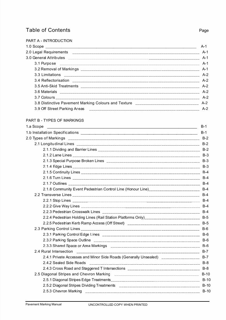
Table of Contents Page
PART A - INTRODUCTION
1.0 Scope ________________________________________________________________________________________________________ A-1
2.0 Legal Requirements ____________________________________________________________ A-1
3.0 General At tributes ______________________________________________________________ A-1
3.1 Purpose __________________________________________________________________ A-1
3.2 Removal of Markings ________________________________________________________ A-1
3.3 Limitations ________________________________________________________________ A-2
3.4 Reflectorisation ____________________________________________________________ A-2
3.5 Anti-Skid Treatments ________________________________________________________ A-2
3.6 Materials __________________________________________________________________ A-2
3.7 Colours ____________________________________________________________________ A-2
3.8 Distinctive Pavement Marking Colours and Texture ______________________________ A-2
3.9 Off Street Parking Areas ____________________________________________________ A-2
PART B - TYPES OF MARKINGS
1.a Scope ________________________________________________________________________ B-1
1.b Installati on Specif ications ________________________________________________________ B-1
2.0 Types of Markings ______________________________________________________________ B-2
2.1 Longitudinal Lines __________________________________________________________ B-2
2.1.1 Dividing and Barrier Lines ________________________________________________ B-2
2.1.2 Lane Lines ____________________________________________________________ B-3
2.1.3 Special Purpose Broken Lines ____________________________________________ B-3
2.1.4 Edge Lines ____________________________________________________________ B-32.1.5 Continuity Lines ________________________________________________________ B-4
2.1.6 Turn Lines ____________________________________________________________ B-4
2.1.7 Outlines ______________________________________________________________ B-4
2.1.8 Community Event Pedestrian Control Line (Honour Line)________________________ B-4
2.2 Transverse Lines ____________________________________________________________ B-4
2.2.1 Stop Lines ____________________________________________________________ B-4
2.2.2 Give Way Lines ________________________________________________________ B-4
2.2.3 Pedestrian Crosswalk Lines ______________________________________________ B-4
2.2.4 Pedestrian Holding Lines (Rail Station Platforms Only)__________________________ B-5
2.2.5 Pedestrian Kerb Ramp Access (Off Street) __________________________________ B-52.3 Parking Control Lines ________________________________________________________ B-6
2.3.1 Parking Control Edge Lines ______________________________________________ B-6
2.3.2 Parking Space Outline __________________________________________________ B-6
2.3.3 Shared Space or Area Markings __________________________________________ B-6
2.4 Rural Intersection __________________________________________________________ B-7
2.4.1 Private Accesses and Minor Side Roads (Generally Unsealed) __________________ B-7
2.4.2 Sealed Side Roads ____________________________________________________ B-8
2.4.3 Cross Road and Staggered T Intersections __________________________________ B-8
2.5 Diagonal Stripes and Chevron Marking ________________________________________ B-10
2.5.1 Diagonal Stripes Edge Treatments__________________________________________ B-102.5.2 Diagonal Stripes Dividing Treatments ______________________________________ B-10
2.5.3 Chevron Marking ______________________________________________________ B-10
UNCONTROLLED COPY WHEN PRINTED

7/25/2019 Road Marking Guidelines
http://slidepdf.com/reader/full/road-marking-guidelines 6/159
Pavement Marking Manual
2.6 Arrows ____________________________________________________________________ B-11
2.6.1 Arrows - Common Type __________________________________________________ B-11
2.6.2 Arrows - Special Type____________________________________________________ B-12
2.6.3 Arrows - Lane Change __________________________________________________ B-13
2.6.4 Arrows - Expressway Exit ________________________________________________ B-13
2.7 Messages and Symbols ______________________________________________________ B-14
2.7.1 Letters and Numbers ____________________________________________________ B-14
2.7.2 Words________________________________________________________________ B-14
2.7.3 Bicycle and Pedestrian Pavement Symbols __________________________________ B-18
2.7.4 International Symbol of Access ____________________________________________ B-22
2.7.4a Accessible Boarding Indicator Patch (station platforms only) ______________ B-22
2.7.4b Identification of Dedicated Parking Space for People With Disabilities ______ B-22
2.7.4.1 Station Platforms ________________________________________________ B-23
2.7.4.2 Dedicated Parking Space Identification & Delineation (angle Parking) ______ B-24
2.8 Railway Level Cross ing Pavement Message ____________________________________ B-25
2.9 Railway Level Crossings Yellow Box Markings __________________________________ B-26
2.10 Zigzag School Zone Markings ________________________________________________ B-27
2.11 Point to Point Safety Camera Markings (Stub Line) ______________________________ B-27
2.12 Raised Road Pavement Markings ____________________________________________ B-27
2.12.1 On Street ____________________________________________________________ B-27
2.12.2 Off Street (Watts Profile 1.2m Length Only)__________________________________ B-28
2.13 Pavement Bars ____________________________________________________________ B-28
2.14 Raised Pavement Markers __________________________________________________ B-30
2.14.1 Dividing and Barrier Lines (Separates Opposing Traffic Flows Only) ______________ B-30
2.14.2 Lane Lines __________________________________________________________ B-33
2.14.3 Edge Lines __________________________________________________________ B-34
2.14.4 Corner Islands ________________________________________________________ B-35
2.14.4.1 Speed Limit <80 ______________________________________________ B-35
2.14.4.2 Speed Limit >90 ______________________________________________ B-35
2.14.5 Freeway/Expressway Type Ramps ________________________________________ B-36
2.14.6 Urban Arterial Road ____________________________________________________ B-39
2.14.7 Rural Multi-lane Road __________________________________________________ B-40
2.14.8 Rural Two-lane Two-way Road __________________________________________ B-41
2.14.9 Rural Intersections ____________________________________________________ B-42
2.14.10 Overtaking Lane - Merge Area Delineation Treatment 80km/h or Greater ________ B-45
2.14.11 Wide Dividing Line Treatment __________________________________________ B-46
2.15 Distinctive Coloured Pavement Areas ________________________________________ B-47
2.16 Outlines and Painted Kerbs __________________________________________________ B-48
2.16.1 Medians ____________________________________________________________ B-48
2.16.2 Roundabouts ________________________________________________________ B-50
2.16.3 Through Lanes and Auxiliary Right Turn Lanes ______________________________ B-51
2.16.4 Other Raised Islands __________________________________________________ B-52
2.16.5 Pedestrian Refuges ____________________________________________________ B-53
2.16.6 Local Area Traffic Management (LATM) ____________________________________ B-53
2.17 Barrier Line Installation ____________________________________________________ B-54
2.17.1 Intersections__________________________________________________________ B-542.17.2 Property Accesses ____________________________________________________ B-54
UNCONTROLLED COPY WHEN PRINTED
7/25/2019 Road Marking Guidelines
http://slidepdf.com/reader/full/road-marking-guidelines 7/159
Pavement Marking Manual
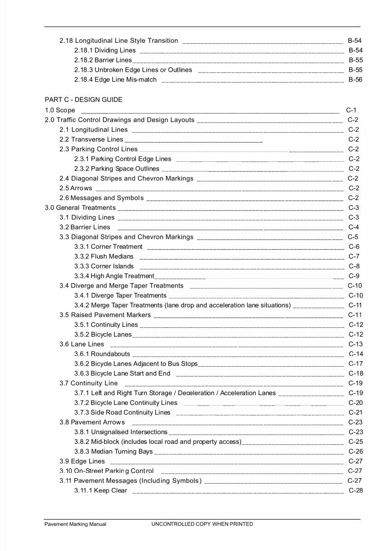
2.18 Longitudinal Line Style Transition ____________________________________________ B-54
2.18.1 Dividing Lines ________________________________________________________ B-54
2.18.2 Barrier Lines__________________________________________________________ B-55
2.18.3 Unbroken Edge Lines or Outlines ________________________________________ B-55
2.18.4 Edge Line Mis-match __________________________________________________ B-56
PART C - DESIGN GUIDE
1.0 Scope ________________________________________________________________________ C-1
2.0 Traffic Control Drawings and Design Layouts ________________________________________ C-2
2.1 Longitudinal Lines __________________________________________________________ C-2
2.2 Transverse Lines ____________________________________________________________ C-2
2.3 Parking Control Lines ________________________________________________________ C-2
2.3.1 Parking Control Edge Lines ______________________________________________ C-2
2.3.2 Parking Space Outlines __________________________________________________ C-2
2.4 Diagonal Stripes and Chevron Markings ________________________________________ C-2
2.5 Arrows ____________________________________________________________________ C-2
2.6 Messages and Symbols ______________________________________________________ C-2
3.0 General Treatments ______________________________________________________________ C-3
3.1 Dividing Lines ______________________________________________________________ C-3
3.2 Barrier L ines ______________________________________________________________ C-4
3.3 Diagonal Stripes and Chevron Markings ________________________________________ C-5
3.3.1 Corner Treatment ______________________________________________________ C-6
3.3.2 Flush Medians ________________________________________________________ C-7
3.3.3 Corner Islands ________________________________________________________ C-8
3.3.4 High Angle Treatment____________________________________________________ C-9
3.4 Diverge and Merge Taper Treatments __________________________________________ C-10
3.4.1 Diverge Taper Treatments ________________________________________________ C-10
3.4.2 Merge Taper Treatments (lane drop and acceleration lane situations) ______________ C-11
3.5 Raised Pavement Markers ____________________________________________________ C-11
3.5.1 Continuity Lines ________________________________________________________ C-12
3.5.2 Bicycle Lanes__________________________________________________________ C-12
3.6 Lane Lines ________________________________________________________________ C-13
3.6.1 Roundabouts __________________________________________________________ C-14
3.6.2 Bicycle Lanes Adjacent to Bus Stops________________________________________ C-17
3.6.3 Bicycle Lane Start and End ______________________________________________ C-18
3.7 Continuity Line ____________________________________________________________ C-193.7.1 Left and Right Turn Storage / Deceleration / Acceleration Lanes __________________ C-19
3.7.2 Bicycle Lane Continuity Lines ____________________________________________ C-20
3.7.3 Side Road Continuity Lines ______________________________________________ C-21
3.8 Pavement Arrows __________________________________________________________ C-23
3.8.1 Unsignalised Intersections ________________________________________________ C-23
3.8.2 Mid-block (includes local road and property access)____________________________ C-25
3.8.3 Median Turning Bays ____________________________________________________ C-26
3.9 Edge Lines ________________________________________________________________ C-27
3.10 On-Street Parking Cont rol __________________________________________________ C-27
3.11 Pavement Messages (Includ ing Symbols) ______________________________________ C-273.11.1 Keep Clear __________________________________________________________ C-28
UNCONTROLLED COPY WHEN PRINTED

7/25/2019 Road Marking Guidelines
http://slidepdf.com/reader/full/road-marking-guidelines 8/159
Pavement Marking Manual
3.11.2 Speed Limits __________________________________________________________ C-29
3.11.3 Other Messages ______________________________________________________ C-29
3.12 Kerb Extensions Markings __________________________________________________ C-29
3.13 Standard Intersections (Local Urban Roads) ____________________________________ C-31
3.14 Give Way and Stop Line Markings ____________________________________________ C-31
3.15 Changed Priority __________________________________________________________ C-33
3.16 Roundabouts ______________________________________________________________ C-34
3.16.1 Single Lane Roundabout ________________________________________________ C-34
3.16.2 Multi-lane T-intersection Roundabout ______________________________________ C-35
3.16.3 Bicycle Lane Approach and Exit to a Single Lane Roundabout __________________ C-35
3.17 Signalised Intersections ____________________________________________________ C-36
3.17.1 Pedestrian Crosswalk Lines______________________________________________ C-37
3.17.2 Stop Lines __________________________________________________________ C-38
3.17.3 Turn Lines____________________________________________________________ C-39
3.17.4 Pavement Arrows______________________________________________________ C-40
3.17.4.1 Multiple Turn Lanes ____________________________________________ C-41
3.17.5 Lane Lines __________________________________________________________ C-44
3.17.6 Non-reflective Raised Pavement Markers __________________________________ C-45
3.18 Expressways ______________________________________________________________ C-46
3.18.1 Expressway Exit Lane Arrows ____________________________________________ C-46
3.19 Path Treatments ____________________________________________________________ C-47
3.19.1 Destination Group Layout ______________________________________________ C-47
3.19.2 Connector Group Layout ________________________________________________ C-47
3.19.3 Shared Use Path T Intersection Layout ____________________________________ C-48
3.19.4 Shared Use Path Intersection Layout ______________________________________ C-49
3.19.5 Shared Use Path T Intersection Offset Layout ______________________________ C-503.20 Pedestr ian Facili ties ________________________________________________________ C-51
3.20.1 Pedestrian Refuge ____________________________________________________ C-51
3.20.2 Emu Crossing ________________________________________________________ C-52
3.20.3 Koala Crossing________________________________________________________ C-53
3.20.4 Wombat and Zebra Crossing ____________________________________________ C-54
3.20.5 Pedestrian Actuated Crossing ____________________________________________ C-55
3.21 School Zones ______________________________________________________________ C-56
3.21.1 Zigzag Marking Position ________________________________________________ C-56
3.21.2 Basic School Zone ____________________________________________________ C-57
3.21.3 Curved Alignment______________________________________________________ C-573.21.4 At Intersections and Emu Crossing ________________________________________ C-58
3.21.5 Undivided Multi-lane Road ______________________________________________ C-58
3.21.6 Divided Multi-lane Road ________________________________________________ C-59
3.22 Bus Facilities ______________________________________________________________ C-59
3.22.1 Placing of Lane Messages ______________________________________________ C-60
3.22.2 Full-time / Part-time Bus Lanes __________________________________________ C-62
3.22.3 Parking Bays in Bus Lanes ______________________________________________ C-63
3.22.4 Bus Only ____________________________________________________________ C-63
3.23 Distinctive Coloured Bicycle Lanes __________________________________________ C-65
3.23.1 Left Turn Deceleration Lane______________________________________________ C-653.23.2 Left Turn Acceleration Lane ______________________________________________ C-66
UNCONTROLLED COPY WHEN PRINTED

7/25/2019 Road Marking Guidelines
http://slidepdf.com/reader/full/road-marking-guidelines 9/159
Pavement Marking Manual
3.23.3 High Angle Left Turn Lane ______________________________________________ C-67
3.23.4 Minor Side Road Junction ______________________________________________ C-67
3.23.5 Bicycle Storage Area (with a bicycle lane) __________________________________ C-68
3.23.6 Bicycle Storage Area (without a bicycle lane) ________________________________ C-69
3.24 Other Bicycle Facilities ______________________________________________________ C-70
3.24.1 Indented Hook Turn ____________________________________________________ C-70
3.24.2 Detector Loop ________________________________________________________ C-71
4.0 Rural Treatments ________________________________________________________________ C-72
4.1 Divided Roads ______________________________________________________________ C-72
4.2 Multi-Lane Undiv ided Roads __________________________________________________ C-72
4.3 Dividing Lines on Rural Roads ________________________________________________ C-72
4.4 Barrier Lines on Rural Roads ________________________________________________ C-72
4.5 Wide Line Div iding Treatments ________________________________________________ C-73
4.6 Lane Lines on Rural Roads __________________________________________________ C-73
4.7 Edge lines on Rural Roads ____________________________________________________ C-744.7.1 Narrow Rural Two-lane Two-way Road ______________________________________ C-74
4.7.2 Standard Rural Two-lane Two-way Road ____________________________________ C-75
4.7.3 Wide Sealed Shoulder Rural Two-lane Two-way Road__________________________ C-76
4.7.4 Multi-lane Divided Road__________________________________________________ C-77
4.8 Audio Tacti le Line Marking (ATLM) ____________________________________________ C-78
4.9 Overtaking Lane Treatments __________________________________________________ C-79
4.9.1 Overtaking Lane - Diverge ______________________________________________ C-79
4.9.2 Overtaking Lane - Merge ________________________________________________ C-80
4.10 Slow Vehicle Turnouts ______________________________________________________ C-81
4.11 Rest Areas ________________________________________________________________ C-834.11.1 Roads With Edge lines__________________________________________________ C-83
4.11.2 Roads Without Edge lines ______________________________________________ C-84
4.11.3 Full Acceleration / Deceleration Lane ______________________________________ C-85
4.11.4 Sealed Shoulders Only__________________________________________________ C-86
4.12 Structures and Obstructions ________________________________________________ C-87
4.13 Floodways and Causeways __________________________________________________ C-89
UNCONTROLLED COPY WHEN PRINTED

7/25/2019 Road Marking Guidelines
http://slidepdf.com/reader/full/road-marking-guidelines 10/159
Pavement Marking Manual
THIS PAGE HAS BEEN LEFT INTENTIONALLY BLANK

7/25/2019 Road Marking Guidelines
http://slidepdf.com/reader/full/road-marking-guidelines 11/159
Pavement Marking Manual A-1
Introduction
PART AINTRODUCTION
1.0 SCOPE
This manual specifies the lines, patterns, symbols, letters and numerals, pavement bars andmarkers used in or on roads, road related areas and other places including kerbs, for the
purpose of regulating, guiding and warning road users, and provides guidelines for appropriate
use.
2.0 LEGAL REQUIREMENTS
An "Instrument of General Approval" has been issued by the Minister for Transport andInfrastructure to Councils, the Commissioner of Highways, and some other road authorities to
use traffic control devices, which includes pavement markings. The conditions of this general
approval, which are required by law under the Road Traffic Act, are contained in Part 2 - Code
of Technical Requirements (The Code) which forms part of ‘Manual of Legal Responsibilitiesand Technical Requirements for Traffic Control Devices’. One of the conditions of general
approval is the requirement that the design, installation, alteration and removal of pavement
markings be in accordance with the Code.
This manual has been developed to conform with the Code and takes into consideration the
relevant Australian Road Rules, Australian Standards, Austroads guidelines and Department of
Planning, Transport and Infrastructure (DPTI) Operational Instructions.
Pavement markings not conforming to this Manual and the Code, such as innovative or non-
standard treatments are not authorised to be used under the Instrument of General Approval
issued by the Minister. Authorisation for such treatments may only be given by the Manager,Technical Services, Department of Planning, Transport and Infrastructure (DPTI), acting as the
Minister’s delegate.
3.0 GENERAL ATTRIBUTES
3.1 PURPOSE
A system of clear, effective and consistently applied pavement markings is essential for the proper regulations, warning and guidance of drivers, cyclists, pedestrians and other
road users.
Pavement markings may guide traffic or give advance warning or may impose restrictions
which are supported by the Road Traffic Act. They may act as a supplement to other
traffic control devices or may be used alone to convey certain regulations, warnings and
guidance.
It is therefore important to ensure that the use of the markings conforms with the legal
requirement mentioned above before they are approved, installed, altered or removed to
avoid possible conflict or confusion, legal or otherwise.
3.2 REMOVAL OF MARKINGS
Where traffic conditions are altered and the existing pavement markings no longer apply
it is essential that those markings be removed, covered or obliterated. It is important that
the end result of removing or covering markings does not leave an impression of the
marking on the road surface which may otherwise be interpreted as a marking in any
lighting and/or weather conditions. It is also important that any covering material create a
surface of a similar skid resistance to that of the surrounding road surface.
In rare cases, redundant pavement markings may be allowed to fade but only whenthese markings cannot be misinterpreted or otherwise create a confusing message to the
road user which may create a safety hazard.
Substantial changes to pavement markings will usually require pavement resurfacing.
UNCONTROLLED COPY WHEN PRINTED

7/25/2019 Road Marking Guidelines
http://slidepdf.com/reader/full/road-marking-guidelines 12/159
Pavement Marking Manual A-2
Introduction
UNCONTROLLED COPY WHEN PRINTED
3.3 LIMITATIONS
Pavement markings have the following limitations:
(a) They may not be clearly visible if the road is wet or dusty, for example near an edge of a median.
(b) They are subject to traffic wear and usually require frequent maintenance.(c) They can be obscured by traffic.
(d) Their effect on skid resistance requires careful choice of materials and precludes the
use of large marked surface areas.
(e) They cannot be applied to unsealed roads.
In spite of these limitations they have the advantage under favourable conditions of
conveying information to the driver without diverting attention from the road.
3.4 REFLECTORISATION
All longitudinal lines except zig zag markings shall be reflectorised. Lane change arrows
as shown in Part B 2.6.3 and painted kerbs as shown in Part B 2.16 shall also be
reflectorised.
3.5 ANTI-SKID TREATMENT
An anti-skid treatment shall be applied to all markings other than longitudinal lines.
3.6 MATERIALS
Road pavements may be marked with paint, thermoplastics, pre-cut sheeting, raised
pavement markers (retro-reflective, non reflective or illuminated) or pavement bars.
3.7 COLOURS
Pavement markings shall be white unless specified as yellow or blue. Yellow shall be used
on pavement bars and to define tram only lanes and areas where parking/stoppingrestrictions apply. Blue is used for disability access. Raised pavement markers may be
white, red or yellow.
Black paint may be used in the gaps and around the edges of pavement markings to
heighten contrast where a light coloured pavement does not allow adequate markingdefinition to be obtained. Where this is being considered advice should first be sought
from Manager, Technical Services, DPTI.
In situations such as community events on temporarily closed roads light blue coloured
pavement markings (known as honour lines) may be used to define pedestrian
boundaries. The preferred width of the line is 50mm (75mm max) and shall be non-
reflective. It should be painted with one coat and allowed to fade, or removed after theevent, to ensure road users are not confused by the markings. These markings are not
considered traffic control devices
3.8 DISTINCTIVE PAVEMENT MARKING COLOURS AND TEXTURE
There is a trend by road authorities to use distinctive coloured pavements and/or textures
to highlight the road surface in a visual, tactile or audible manner. Such treatments may
supplement traffic control devices (e.g. Bus Only areas, bicycle lanes and islands) or theymay be aesthetic marking devices to supplement streetscape designs. For commonly used
distinctive coloured pavement marking used in South Australia, refer to Part B 2.15.
3.9 OFF STREET PARKING AREAS
AS 2890.1 and AS 2890.6 are used in South Australia for off street car parking pavement
markings.

7/25/2019 Road Marking Guidelines
http://slidepdf.com/reader/full/road-marking-guidelines 13/159
PART BTYPES OF MARKINGS
1.0 SCOPE
This Section describes the types of marking used including paint substitutes, pavement bars, raised
pavement markers and coloured areas.
It details the actual dimensions and other specification attributes of markings which need not
be shown on traffic control and road design drawings.
IMPORTANT :
All drawings are not to scale. The reader shall use the dimensions specified throughout the manual.
DO NOT SCALE OFF DRAWINGS.
1.1 INSTALLATION SPECIFICATIONS
DPTI shall and all other road authorities should require pavement marking to be installed in
accordance with DPTI Master Specification Division 2: Roadworks
Part 245 Supply of Materials for Pavement Markings
Part 246 Application of Pavement Marking
Part 247 Application of Audio Tactile Line Marking
These documents can be found at http://www.dpti.sa.gov.au/contractor_documents/specifications
Pavement Marking Manual B-1
Types of Markings
B
UNCONTROLLED COPY WHEN PRINTED
7/25/2019 Road Marking Guidelines
http://slidepdf.com/reader/full/road-marking-guidelines 14/159
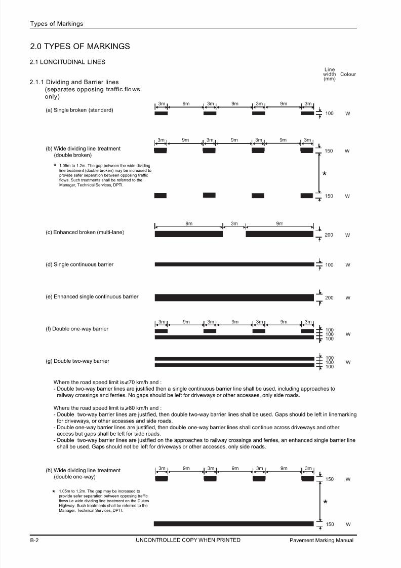
2.1 LONGITUDINAL LINES
2.1.1 Dividing and Barrier lines
(separates opposing traffic flows
only)
(a) Single broken (standard)
(b) Wide dividing line treatment
(double broken)
(c) Enhanced broken (multi-lane)
(d) Single continuous barrier
(e) Enhanced single continuous barrier
(f) Double one-way barrier
(g) Double two-way barrier
(h) Wide dividing line treatment(double one-way)
Pavement Marking ManualB-2
Types of Markings
3m 9m 3m 9m 3m 9m 3m (mm)
100 W▼
▼
▼ ▼
▼ ▼
▼ ▼
▼ ▼
▼ ▼
▼ ▼
▼ ▼
W200
▼
▼
9m 3m 9m ▼ ▼
▼ ▼
▼ ▼
2.0 TYPES OF MARKINGS
Linewidth(mm)
Colour
Where the road speed limit is <70 km/h and :
- Double two-way barrier lines are justified then a single continuous barrier line shall be used, including approaches to
railway crossings and ferries. No gaps should be left for driveways or other accesses, only side roads.
Where the road speed limit is >80 km/h and :
- Double two-way barrier lines are justified, then double two-way barrier lines shall be used. Gaps should be left in linemarking
for driveways, or other accesses and side roads.
- Double one-way barrier lines are justified, then double one-way barrier lines shall continue across driveways and otheraccess but gaps shall be left for side roads.
- Double two-way barrier lines are justified on the approaches to railway crossings and ferries, an enhanced single barrier line
shall be used. Gaps should not be left for driveways or other accesses, only side roads.
UNCONTROLLED COPY WHEN PRINTED
3m 9m 3m 9m 3m 9m 3m
150 W▼
▼
▼ ▼
▼ ▼
▼ ▼
▼ ▼
▼ ▼
▼ ▼
▼ ▼
150 W▼
▼
*1.05m to 1.2m. The gap between the wide dividing
line treatment (double broken) may be increased to
provide safer separation between opposing traffic
flows. Such treatments shall be referred to the
Manager, Technical Services, DPTI.
*
3m 9m 3m 9m 3m 9m 3m
150 W▼
▼
▼ ▼
▼ ▼
▼ ▼
▼ ▼
▼ ▼
▼ ▼
▼ ▼
150 W▼
▼
*
1.05m to 1.2m. The gap may be increased to
provide safer separation between opposing trafficflows i.e wide dividing line treatment on the Dukes
Highway. Such treatments shall be referred to the
Manager, Technical Services, DPTI.
*

7/25/2019 Road Marking Guidelines
http://slidepdf.com/reader/full/road-marking-guidelines 15/159
Pavement Marking Manual B-3
Types of Markings
B
Linewidth(mm)
Colour
W80▼
▼
UNCONTROLLED COPY WHEN PRINTED
(i) Wide dividing line treatment
(double two-way)
(j) Continuous
(bicycle and shared paths off road)
2.1.2 Lane lines
(a) Standard broken
(b) Continuous
2.1.3 Special purpose broken lines
2.1.4 Edge lines
(a) ** Standard
- All roads with sealed shoulders
unless (b) below, applies.
(b) ** Enhanced- Dukes Highway
- Sturt Highway
- Riddoch Highway
- Pt Wakefield Highway
- Augusta Highway- Princes Highway
(Murray Bridge toTailem Bend)
- Port River Expressway
- Northern Expressway- Southern Expressway
- North-South Motorway
- All dual carriageway roads with
sealed shoulders > 0.5m
150 W▼
▼
150 W▼
▼
*
1.05m to 1.2m. The gap may be increased to
provide safer separation between opposing traffic
flows i.e wide dividing line treatment on the Dukes
Highway. Such treatments shall be referred to the
Manager, Technical Services, DPTI.
*
** Note: Should there be just a few kilometres of sealed shoulder >0.5 metres in the
middle of a route (between townships) with sealed shoulder <0.5 metres, the edge line
should be applied with a transition to existing, refer to Part B 2.18.4
Colour : W = White, Y = Yellow and B = Blue

7/25/2019 Road Marking Guidelines
http://slidepdf.com/reader/full/road-marking-guidelines 16/159
Pavement Marking ManualB-4
Types of Markings
W100▼
▼
600mm stripe and gap ▼
▼ ▼
▼ ▼
▼ ▼
▼ ▼
▼ ▼
▼ ▼
▼ ▼
▼ ▼
▼ ▼
▼ ▼
▼ ▼
▼ ▼
▼
Linewidth(mm)
Colour
UNCONTROLLED COPY WHEN PRINTED
ads as determine
2.1.5 Continuity lines
(a) Standard
(b) Enhanced (used in conjunction with
150mm edge lines)
2.1.6 Turn lines
2.1.7 Outlines
(a) Standard
(b) Enhanced (roads where 150mm edgelines are used, see Part B 2.1.4 (b)
2.1.8 Community event pedestrian control
line (honour line)
2.2 TRANSVERSE LINES
2.2.1 Stop li nes
(a) Standard (<70 km/h)
(b) Enhanced (>80 km/h
2.2.2 Give way lines
(a) Standard (<70 km/h)
(b) Enhanced (>80 km/h)
2.2.3 Pedestrian crosswalk lines
(a) Standard (pedestrian actuated crossings,pedestrian crossings at signalised
intersections, koala and emu crossings)
NOTE: When a road is resealed or a new
scheme is required, the above
shall be used.
(b) Previous standard (For maintenance
purposes only. Not to be used forplanning/design)
450
▼
▼W
600mm stripe and gap ▼
▼ ▼
▼ ▼
▼ ▼
▼ ▼
▼ ▼
▼ ▼
▼ ▼
▼ ▼
▼ ▼
▼ ▼
▼ ▼
▼ ▼
▼
600
▼
▼
W
600mm stripe and gap ▼
▼ ▼
▼ ▼
▼ ▼
▼ ▼
▼ ▼
▼ ▼
▼ ▼
▼ ▼
▼ ▼
▼ ▼
▼ ▼
▼ ▼
▼
150▼
▼ W
▼ ▼
▼ ▼
▼ ▼
▼ ▼
▼ ▼
▼ ▼
▼ ▼
▼ ▼
▼ ▼
▼ ▼
▼ ▼
▼ ▼
▼ ▼ ▼
▼ ▼ ▼
600mm stripe and 300mm gap
150▼
▼ W
1m stripe and 300mm gap
▼ ▼
▼ ▼
▼ ▼
▼ ▼
▼ ▼
▼ ▼
▼ ▼
▼ ▼
▼ ▼
B50▼ ▼

7/25/2019 Road Marking Guidelines
http://slidepdf.com/reader/full/road-marking-guidelines 17/159
Pavement Marking Manual B-5
Types of Markings
B
Linewidth(mm)
Colour
UNCONTROLLED COPY WHEN PRINTED
* ▼ ▼
▼ ▼
▼ ▼
▼ ▼
▼ ▼
▼ ▼
▼ ▼
▼ ▼
▼ ▼
▼ ▼
▼ ▼
▼ ▼
▼ ▼*
W
3m min
off street
6m min
on street
(wombat)▼
600mm stripe and gap
K e r b
K er b
▼
Y100▼
▼
* Equal, 600mm or less
2.2.5 Pedestrian kerb ramp access (off street)
Access to kerb ramps between parking spaces may be marked with diagonal stripes to discourage drivers from impeding
access to the ramp. Where marked they shall be white.
150mm
approx
600mm
Detail A
2 0 0
- 3 0 0
m m
100mm
100mm45%
parking aisle
See Detail A
path / walkway
1.8m (preferred)
NOTE : For new works and large car parks, consideration should be
given to raised kerb extensions and/or formal pedestriancrossings e.g wombat crossings.
(c) Wombat and Zebra crossings
2.2.4 Pedestrian holding li nes (rail station platforms only)Refer to Part B 2.7.4.1 for layout of platform markings.
(a) Platform edge hazard line
(b) Platform ‘wait behind’ line
Colour : W = White, Y = Yellow and B = Blue

7/25/2019 Road Marking Guidelines
http://slidepdf.com/reader/full/road-marking-guidelines 18/159
Pavement Marking ManualB-6
Types of Markings
UNCONTROLLED COPY WHEN PRINTED
Y100
▼
▼
Y100▼
▼
▼ ▼
▼ ▼
▼ ▼ ▼ ▼
▼ ▼
▼ ▼
▼ ▼
600mm stripe and 900mm gap
Y100▼
▼
▼ ▼ ▼ ▼
▼ ▼
▼ ▼
▼ ▼
▼ ▼
▼ ▼
900mm stripe and 600mm gap
2.3 PARKING CONTROL LINES
2.3.1 Parking control edge lines
(a) *No Stopping at all times
(b) *Restricted parking other than
Clearway
2.3.2 Parking space outline
(a) All vehicles/*no restrictions
(individual bays may be marked)
(b) *Restricted vehicle type and/or part-
time restriction (individual bays
may be marked).
(3) **Parking for people with disabilities
* Restricted Parking: Parking restriction by time and/or by vehicle type
Y100▼
▼
** Dedicated parking spaces for people with disabilities shall be outlined
on all sides excepting any side delineated by a kerb, barrier or wall.
2.3.3 Shared space or area markings
Within off street car parking areas, shared areas or spaces located adjacent to the longitudinal side only of dedicated angle
parking spaces for people with disabilities shall have a yellow outline and yellow diagonal stripes with a slip resistant surface.
Yellow diagonal stripes shall not be used in trafficked areas including walkways within or partly within a shared area, parkingaisles or roadways.
Walkways within or partly within a shared area or space shall be marked with yellow 100mm wide unbroken longitudinal lines on
both sides of the walkway excepting any side delineated by a kerb, barrier or wall (see Part B 2.7.4.2).
150mm
approx
600mm
2 0 0
- 3 0 0
m m
100mm
100mm 45%
dedicated
space
Colour : W = White, Y = Yellow and B = Blue

7/25/2019 Road Marking Guidelines
http://slidepdf.com/reader/full/road-marking-guidelines 19/159
Pavement Marking Manual B-7
Types of Markings
B
UNCONTROLLED COPY WHEN PRINTED
2.4 RURAL INTERSECTIONS
For more information regarding gaps in barrier lines see Part B 2.18.
For more intersection examples see Part B 2.14.6 - 2.14.8, Part C 3.7 and 3.13 - 3.15.
2.4.1 Private accesses and minor side roads (generally unsealed)
TP
TP
TP
privateaccess
TP
TP
TP
TP
private
access
TP
TP
TP
TP
private
access
10m *
10m *
TP
TP
TP
TP
private
access
10m
10m
5m
Inset B
TP
TP
10m
Inset A
TP
TP
road
road
road
road
road
road
road
road
TP
10m
10m
TP
TP
NOTES: 1. The gap in the edge line for side roads starts/ends at the tangent point or clear of the vehicle turning envelope.
2. Where sufficient width is available on the sealed shoulder or apron, a Give Way line or Stop line (in accordance with
AS1742.2 - 2009 Section 2.5.4) may be installed. See Inset A for example.
3. Continuity line may be used across wide side roads, generally wider than 12m TP to TP. See Inset B for example and
Part C 3.7.
4. Edge line type (see part B 2.1.4) or no edge line.
* Australian Road Rule 134 allows a driver to cross double one-way barrier lines to enter or leave the road. Nevertheless a gap of 10m
is provided to provide drivers with a visual cue to the location of a side road and where to prop.
7/25/2019 Road Marking Guidelines
http://slidepdf.com/reader/full/road-marking-guidelines 20/159
Pavement Marking ManualB-8
Types of Markings
UNCONTROLLED COPY WHEN PRINTED
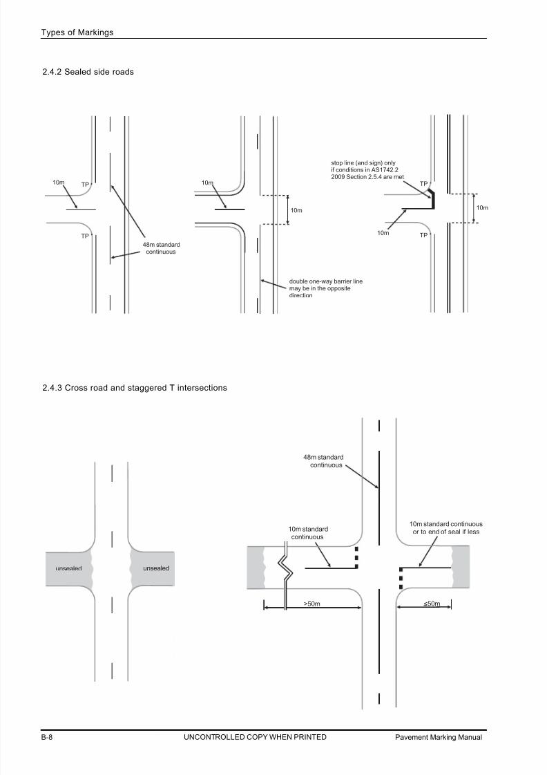
2.4.2 Sealed side roads
2.4.3 Cross road and staggered T intersections
10m TP
TP
10m
10m
TP
TP
10m
double one-way barrier linemay be in the oppositedirection
10m
stop line (and sign) onlyif conditions in AS1742.22009 Section 2.5.4 are met
48m standard continuous
48m standard continuous
10m standard continuous
10m standard continuous or to end of seal if less
unsealed unsealed
>50m <50m

7/25/2019 Road Marking Guidelines
http://slidepdf.com/reader/full/road-marking-guidelines 21/159
Pavement Marking Manual B-9
Types of Markings
B
UNCONTROLLED COPY WHEN PRINTED
5m
TP
TP
TP
TP
TP
TP
TP
TP
10m
10m
TP
TP
TP
TP
5mcL
cL
gap in continuousline only
2.4.3 Cross road and staggered T intersections (cont)
10m
TP
TP
TP
TP
10m3m minimum
5m
TP
TP
TP
TP
5mcL
cL
Note: For small offsets consider using continuity line across the side roads, see Part C 3.7

7/25/2019 Road Marking Guidelines
http://slidepdf.com/reader/full/road-marking-guidelines 22/159
Pavement Marking ManualB-10
Types of Markings
UNCONTROLLED COPY WHEN PRINTED
2.5 DIAGONAL STRIPES AND CHEVRON MARKINGS
▼
▼
▼
▼
Outline / Edgeline
100mm▼
▼
▼
1 .0 m
▼
▼
* 1 . 0
m
▼
**100mm
100mm
▼
▼
▼
X
~ 450
~ 450
Outline / Edgeline
100mm▼
▼
▼
1 . 0 m
▼
▼
* 1 . 0
m
▼
**100mm
100mm
▼
▼
▼
▼
▼
X
~ 450
Outline / Edgeline
100mm▼
▼
▼
~ 450
▼
▼
Edge o f wa ter table or seal
1 . 0 m
▼
▼
* 1 . 0
m
▼
▼
**100mm100mm
▼
▼
▼
X
2.5.2 Diagonal stripes dividing treatment
2.5.3 Chevron markings
* 1st diagonal marking or chevron is placed where the width of the treatment is 1.0m.
2.5.1 Diagonal stripes edge treatment
** In rare cases wider outlines/edge lines may be specified on traffic control drawings.
~ 45%= nominally 45 degrees
x - Spacing may be modified to suit corner islands, flush medians and merges.
For design details see Part C 3.3 and Part C 3.12.
Indicates direction of travel

7/25/2019 Road Marking Guidelines
http://slidepdf.com/reader/full/road-marking-guidelines 23/159
Pavement Marking Manual B-11
Types of Markings
B
UNCONTROLLED COPY WHEN PRINTED
2.6 ARROWS
X= 100Y
Centre of lane
Centre of lane
Centre of lane
2.6.1 Arrows - common types

7/25/2019 Road Marking Guidelines
http://slidepdf.com/reader/full/road-marking-guidelines 24/159
Pavement Marking ManualB-12
Types of Markings
UNCONTROLLED COPY WHEN PRINTED
Centre of lane
Centre of lane
X= 100Y
Centre of lane(a) Double turn
arrow
(b) U- turn arrow
(c) 45% turn
arrow
(d) Through right
left turn arrow
Centre of lane
Centre of lane
2.6.2 Arrows - special types

7/25/2019 Road Marking Guidelines
http://slidepdf.com/reader/full/road-marking-guidelines 25/159
Pavement Marking Manual B-13
Types of Markings
B
UNCONTROLLED COPY WHEN PRINTED
900 650
2m
4m
2m
2m
4m
e d g e of l a n e
e
d g e of l a n e
c e n t r e l i n e
of l a n e
150
e d g e of l a n e
e
d g e of l a n e
c e n t r e l i n e
of l a n e
875
3.1m
2.7m
2m
4m
150
725
630200
200
1880
1000
1400
580
550
1310
780
600
780
880
860
780
1500
7500
60
e d g e of l a n e
e d g e of l a n e
c e n t r e l i n e
of l a n e
780
2.6.3 Arrows - lane change
2.6.4 Arrows - expressway exit
NOTES: 1. Lane change arrows shall not be used in SA without the
approval of Manager, Technical Services, DPTI,
other than at the termination of overtaking lanes.
2. Previous arrow design may continue to be used for
maintenance purpose only.

7/25/2019 Road Marking Guidelines
http://slidepdf.com/reader/full/road-marking-guidelines 26/159
Pavement Marking ManualB-14
Types of Markings
UNCONTROLLED COPY WHEN PRINTED
NOTES:
The grid width (X) is constant at 100 mm, but the grid height
(Y) may vary as follows:
Y = Height of letter or numeral required (mm)40
However the word AHEAD may be made narrower
(eg grid width reduced to 75mm) to fit into a lane.
2.7.1 Letters and Numerals
Letters and numerals other than those shown in Words (Part B 2.7.2) are available from Australian Standard 1742.2.
The length of letters and numerals shall be 2.5m where the speed limit is up to 80km/h and 5.0m at higher speed
limits unless otherwise specified.
2.7.2 Words
Refer to Part C 3.11.1 for the placement of KEEP CLEAR messages and Part B 2.8 for the placement of RAIL Xmessages.
2.7 MESSAGES AND SYMBOLS
X Y

7/25/2019 Road Marking Guidelines
http://slidepdf.com/reader/full/road-marking-guidelines 27/159
Pavement Marking Manual B-15
Types of Markings
B
UNCONTROLLED COPY WHEN PRINTED
YX
NOTES:
The grid width (X) is constant at 100 mm, but the grid height (Y) may vary as follows:
Y = Height of letter or numeral required (mm)40
2.7.2 Words (cont)

7/25/2019 Road Marking Guidelines
http://slidepdf.com/reader/full/road-marking-guidelines 28/159
Pavement Marking ManualB-16
Types of Markings
UNCONTROLLED COPY WHEN PRINTED
Y
NOTES:
The grid width (X) is constant at 100 mm, but the grid height (Y) may vary as follows:Y = Height of letter or numeral required (mm)
40
2.7.2 Words (cont)

7/25/2019 Road Marking Guidelines
http://slidepdf.com/reader/full/road-marking-guidelines 29/159
Pavement Marking Manual B-17
Types of Markings
B
UNCONTROLLED COPY WHEN PRINTED
YX
NOTES:
The grid width (X) is constant at 100 mm, but the grid height (Y) may vary as follows:Y = Height of letter or numeral required (mm)
40
2.7.2 Words (cont )

7/25/2019 Road Marking Guidelines
http://slidepdf.com/reader/full/road-marking-guidelines 30/159
Pavement Marking ManualB-18
Types of Markings
UNCONTROLLED COPY WHEN PRINTED
XXX= 50
2.7.2 Words (cont)
2.7.3 Bicycle and pedestrian pavement symbols
X
X
C e n
t r e o f l a n e
Pedestrian pavement symbol
(path only)
X=75mm
X
X
C e n t r e o f
l a n e
Arrow pavement symbol
(path only)
X=100mm

7/25/2019 Road Marking Guidelines
http://slidepdf.com/reader/full/road-marking-guidelines 31/159
Pavement Marking Manual B-19
Types of Markings
B
UNCONTROLLED COPY WHEN PRINTED
2.7.3 Bicycle and pedestrian pavement symbols (cont)
Y
X
X
w a t e r t a b l e
k e r b
l a n e l i n e
do not paint part of the bicycle symbolindicated in gray.
50mmFor bicycle lanes less then 1.2m, bicycle pavement symbol may be reducedproportionally. As an atternative parts of the bicycle pavement symbol may
be omitted to ensure the symbol fits within the lane (refer to right diagram).
Bicycle pavement symbol
Road X = 65mm
Path X = 28mm
Road Y = 1800mm
Path Y = 800mm

7/25/2019 Road Marking Guidelines
http://slidepdf.com/reader/full/road-marking-guidelines 32/159
Pavement Marking ManualB-20
Types of Markings
UNCONTROLLED COPY WHEN PRINTED
X
X
300mm
1220mm
2.7.3 Bicyc le and pedestrian pavement symbols (cont)
X=30mm
No-Bicycles Pavement symbol for path use

7/25/2019 Road Marking Guidelines
http://slidepdf.com/reader/full/road-marking-guidelines 33/159
Pavement Marking Manual B-21
Types of Markings
B
UNCONTROLLED COPY WHEN PRINTED
X X
2.7.3 Bicyc le and pedestrian pavement symbols (cont)
X=24mm
Al l skaters prohibited

7/25/2019 Road Marking Guidelines
http://slidepdf.com/reader/full/road-marking-guidelines 34/159
Pavement Marking ManualB-22
Types of Markings
UNCONTROLLED COPY WHEN PRINTED
2.7.4 International symbol of access
2.7.4.a Accessible boarding indicator patch (station platforms only)
1000mm
786mm1000mm
160mm
2.7.4.b Identification of dedicated parking space for people with disabilities
1200mm max
1200mm max 800 - 1000mm
NOTE:The grid is for positional purposes
The colour used for the blue background
shall be “Ultramarine” (AS2700-B21)
Symbol shall be centrally located
within the blue background
The colour used for the blue background
shall be “Ultramarine” (AS2700-B21)
Symbol shall be centrally locatedwithin the blue background

7/25/2019 Road Marking Guidelines
http://slidepdf.com/reader/full/road-marking-guidelines 35/159
Pavement Marking Manual B-23
Types of Markings
B
UNCONTROLLED COPY WHEN PRINTED
2.7.4.1 Station p latforms
100mm yellow line
100mm white line
6 0 0
m m
6 0 0
m m
PLATFORM AREA
Accessible Boarding Indicator Patch
Tactile ground surface indicators
Note : For design requirements specific to station platforms, contact DPTI Technical Services.

7/25/2019 Road Marking Guidelines
http://slidepdf.com/reader/full/road-marking-guidelines 36/159
Pavement Marking ManualB-24
Types of Markings
UNCONTROLLED COPY WHEN PRINTED
2.7.4.2 Dedicated parking space identification & delineation (angle parking)
Each dedicated parking space for people with disabilities shall be identified by a white symbol of access on a bluebackground in the centre of the space between 500mm and 600mm from its entry point.
kerb, bar rier or wall
500 to
600mm
other parking
spaces
dedicated space
Parking aisle
2.4m 2.4m
Either :
- end of parking module
- dedicated space
- other parking spaces
shar ed space
bollard
800mm
50+ _
ker b, barr ier or wall
500 to
600mm
primary access
path
other parking
spaces
dedicated space
2.4m
Either :
- end of parking module
- dedicated space
- other parking spaces
Tactile ground
surface indicators
Parking aisle
2.4m minimum
when adjacent to a dedicated
parking space for people with
disabilities.
Note : The primary access path or the shared
space can be located on the left or
right side of the dedicated space.
7/25/2019 Road Marking Guidelines
http://slidepdf.com/reader/full/road-marking-guidelines 37/159
Pavement Marking Manual B-25
Types of Markings
B
UNCONTROLLED COPY WHEN PRINTED
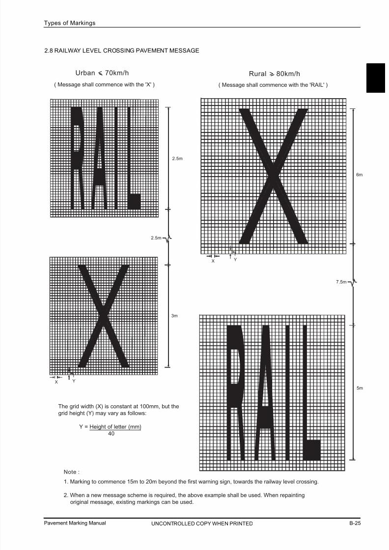
2.8 RAILWAY LEVEL CROSSING PAVEMENT MESSAGE
5m
6m
7.5m
3m
Urban < 70km/h Rural > 80km/h
( Message shall commence with the 'X' ) ( Message shall commence with the 'RAIL' )
Note :
1. Marking to commence 15m to 20m beyond the first warning sign, towards the railway level crossing.
2. When a new message scheme is required, the above example shall be used. When repainting
original message, existing markings can be used.
2.5m
YX
YX
2.5m
The grid width (X) is constant at 100mm, but the
grid height (Y) may vary as follows:
Y = Height of letter (mm)
40

7/25/2019 Road Marking Guidelines
http://slidepdf.com/reader/full/road-marking-guidelines 38/159
Pavement Marking ManualB-26
Types of Markings
UNCONTROLLED COPY WHEN PRINTED
2.9 RAILWAY LEVEL CROSSINGS YELLOW BOX MARKINGS
150mm yellow lines
0.5m gap
5 . 0 m m
i n i m u m
R A I L W A Y
T R A C K S
150mm yellow lines
45% 2 . 0 m
2 . 0 m
Parallel to track
45%
150mm
NOTE:
When a new scheme is required, the above example shall be used.When repainting original box markings, existing lines can be used.
Refer to AS1742.7 for the warrants for box markings.
0.5m
150mm0.5m
150mm
If a bicycle lane is installed

7/25/2019 Road Marking Guidelines
http://slidepdf.com/reader/full/road-marking-guidelines 39/159
Pavement Marking Manual B-27
Types of Markings
B
UNCONTROLLED COPY WHEN PRINTED
2.12 RAISED ROAD PAVEMENT MARKINGS
Includes Flat-top Road Humps, Watts profile (3.7m length), Wombat Crossings (on street and off street) and
Raised Intersections.
1000
See Detail A Nominal start of ramp
Nominal start of ramp
'Inverted Piano Key' marking
400mm
Kerbface
400mm
1000mm
0 to 300mm
200mm
Kerbface Detail A
(measurements are in mm)
500
200
200
200
500
500
200
200mm
1000mm
0 to 300mm
Nominal topof ramp
2.10 ZIGZAG SCHOOL ZONE MARKINGS
1.1m
6.0m
30.0m
150mm
NOTE:
ZIGZAG marking commences 30m in advance of School Zone Sign.
2.11 POINT TO POINT SAFETY CAMERA MARKINGS (STUB LINE)
Edge line or
lane line
400mm
100mm
400mm
Dividing line
100mm
400mm
D i r e c t i o n o f t r a v e l
D i r e c t i o n o f t r a v e l
D i r e
c t i o n o f t r a v e l
2.12.1 On street

7/25/2019 Road Marking Guidelines
http://slidepdf.com/reader/full/road-marking-guidelines 40/159
Pavement Marking ManualB-28
Types of Markings
UNCONTROLLED COPY WHEN PRINTED
2.13 PAVEMENT BARS
2.12.2 Off st reet (Watts profile 1.2m length only)
500
See Detail B Detail B
(measurements are in mm)
500
200 200
200
500
300
200 Edge of road hump
Edge of road hump
Edge of road
The transverse part of the pavement marking is placedon the original road in front of the road hump.
1200
r o a d h u m p
100mm radius
385mm
200mm
PLAN
FRONT ELEVATION END ELEVATION
10mm
nominal 140mm r adius
chamfer 1 in 5
all round
NOTE: 1. Not to scale
2. Size B Bars 50mm nominal height.

7/25/2019 Road Marking Guidelines
http://slidepdf.com/reader/full/road-marking-guidelines 41/159
Pavement Marking Manual B-29
Types of Markings
B
UNCONTROLLED COPY WHEN PRINTED
75mm
Outline or edge line
75mm min
Single row Double row, triple row etc
90%
75mm
Outline or edge line
90%
NOTE:
Pavement bars shall not be used where *85th percentile approach speeds are greater than 75km/h. (The use of yellowRRPMs is an alternative, refer to inset Part B 2.14.9).
Standard pavement bar median may be supplemented by RRPMs where physical turning control is less important. See
Part B 2.14.9.
Pavement bars shall always be placed at 90 degrees to the direction of traffic.
90%
A
A
BB
90%
Where used to supplement diagonal markings or chevrons,
pavement bars shall be placed centrally (longitudinally)
between the markings
* 85th percentile speed (V85 km/h) - the speed at or below which 85% of vehicles are observed to travel under free-flowing conditions past a nominated
point. A vehicle is considered to be operating under free-flowing conditions when the preceding vehicle has at least 4 s headway and there is no apparent
Control of turn ing movements at intersections
Note :
75mm gap
1.5m
The 9m length using 4 bars at 3m spacing may be extended to 18m using 7 bars at 3m spacing.
3m 750mm
1.5m
400mm 750mm
9m10m taper
100mm
attempt to overtake the vehicle ahead.
2.13 PAVEMENT BARS (cont )

7/25/2019 Road Marking Guidelines
http://slidepdf.com/reader/full/road-marking-guidelines 42/159
Pavement Markings ManualB-30 UNCONTROLLED COPY WHEN PRINTED
Types of Markings
2.14.1 Dividing and Barrier lines
(separates opposing traffic flowsonly)
(a) Single broken (standard), unlit
(b) Single broken (standard), lit
(c) Enhanced broken (multi-lane),
unlit
(d) Enhanced broken (multi-lane),
lit
(e) Single continuous (standard),
unlit
2.14 RAISED PAVEMENT MARKERS
4.5m
24m
4.5m
12m
24m
25mm min
50mm max
1.5m
24m
1.5m
12m
SYMBOLS FOR RAISED PAVEMENT MARKERS
Retroreflective raised pavement marker :
Unidirectional - White
Marker Symbol
Line extension on symbol indicates direction of reflection.
Lane lines, small* channelizing island outline,
painted or raised - all sides.
COLOUR OF RETROREFLECTIVE RAISED PAVEMENT
MARKERS TO AUGMENT PAINTED LINES
Appl ications RRPM colour
Left hand edgeline, divided and 2-way roads.
Left side of diverge outline, including expressway
exit nose, and approach end of large island.
White
Red
Yellow
Dividing lines, right hand edgeline (divided road),
median island outline, painted or raised - all sides.
Tram lane lines.
Right side (when viewed in the direction of travel)of exit lane on diverge outline, including
expressway exit nose, and approach end of large
island.
* A small island should generally be regarded as one with no side
longer than 12m including approach and departure markings.
Non-retroreflective raised pavement marker
- Yellow
- Red
Face of marker to be normal to direction of travel.
Bidirectional - Yellow

7/25/2019 Road Marking Guidelines
http://slidepdf.com/reader/full/road-marking-guidelines 43/159
Pavement Markings Manual B-31
B
Types of Markings
UNCONTROLLED COPY WHEN PRINTED
(f) Single continuous (standard),
lit
(g) Enhanced continuous barrier,
unlit
(h) Enhanced continuous barrier,
lit
(i) Double one-way barrier, unlit
(j) Double one-way barrier, lit
(k) Double two-way barrier, unlit
(l) Double two-way barrier, lit
(m) Outline urban roads, unlit
12m
25mm min
50mm max
4.5m
24m
25mm min
50mm max
4.5m
12m
25mm min
50mm max
24m
25mm min
50mm max
12m
25mm min
50mm max
24m
25mm min
50mm max
12m
25mm min
50mm max
median or island kerb
24m 25mm min
50mm max
edge of kerb
7/25/2019 Road Marking Guidelines
http://slidepdf.com/reader/full/road-marking-guidelines 44/159
Pavement Marking ManualB-32
Types of Markings
UNCONTROLLED COPY WHEN PRINTED
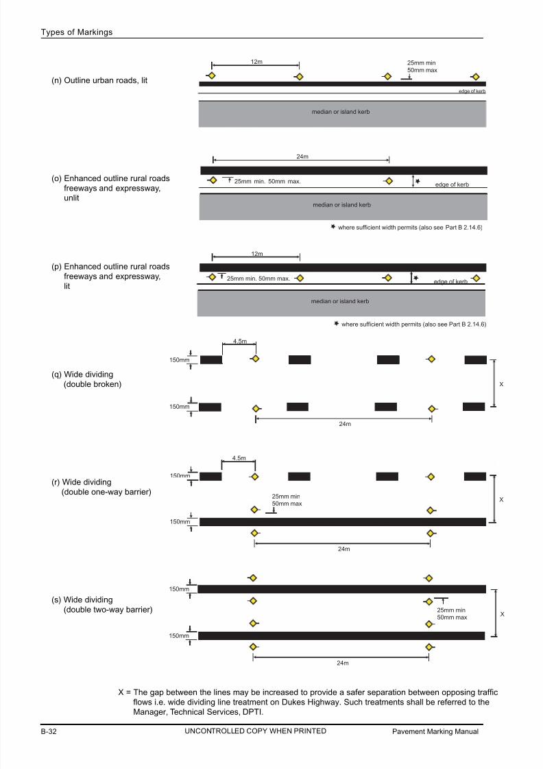
(n) Outline urban roads, lit
(o) Enhanced outline rural roads
freeways and expressway,unlit
(p) Enhanced outline rural roadsfreeways and expressway,
lit
(q) Wide dividing
(double broken)
(r) Wide dividing
(double one-way barrier)
(s) Wide dividing
(double two-way barrier)
24m
4.5m
150mm
150mm
X
24m
25mm min
50mm max
4.5m
150mm
150mm
X
24m
25mm min
50mm max
150mm
150mm
X
X = The gap between the lines may be increased to provide a safer separation between opposing traffic
flows i.e. wide dividing line treatment on Dukes Highway. Such treatments shall be referred to the
Manager, Technical Services, DPTI.
12m 25mm min
50mm max
median or island kerb
edge of kerb
25mm min. 50mm max.
24m
where sufficient width permits (also see Part B 2.14.6)
median or island kerb
edge of kerb
12m
25mm min. 50mm max.
median or island kerb
where sufficient width permits (also see Part B 2.14.6)
edge of kerb

7/25/2019 Road Marking Guidelines
http://slidepdf.com/reader/full/road-marking-guidelines 45/159
Pavement Marking Manual B-33
Types of Markings
B
UNCONTROLLED COPY WHEN PRINTED
24m
25mm min
50mm max
12m
25mm min
50mm max
4.5m
24m
4.5m
12m
Note: Direction of travel is left to right in above diagrams.
2.14.2 Lane lines
(a) Broken, unlit
(b) Broken, lit
(c) Continuous, unlit. Markersmay be on left or right of line.
(d) Continuous, lit. Markers may
be on left or right of line.
(e) Special purpose lane line,
unlit
(f) Special purpose lane line,
lit
1.5m
24m
1.5m
12m

7/25/2019 Road Marking Guidelines
http://slidepdf.com/reader/full/road-marking-guidelines 46/159
Pavement Marking ManualB-34
Types of Markings
UNCONTROLLED COPY WHEN PRINTED
2.14.3 Edge lines
(a) Standard, unlit
(b) Standard, lit
(c) Enhanced, unlit
(d) Enhanced, lit
24m
25mm min
50mm max
12m
25mm min
50mm max
24m
25mm min
50mm max
12m
25mm min
50mm max
Note: Direction of travel is left to right in above diagrams.
NOTES: 1. Edge lines in the merge taper on overtaking lanes from this specification (see Part B 2.14.10).
2. RRPM shall not be used on narrow sealed shoulders <0.5 metres.3. RRPM shall be placed to the left of the edge line (direction of travel) where sealed shoulder width is > 0.5 metres.
7/25/2019 Road Marking Guidelines
http://slidepdf.com/reader/full/road-marking-guidelines 47/159
Pavement Marking Manual B-35
Types of Markings
B
UNCONTROLLED COPY WHEN PRINTED
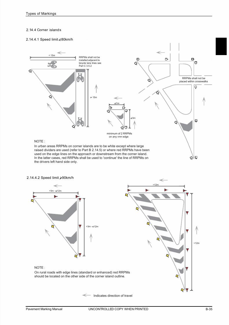
2.14.4 Corner islands
Indicates direction of travel
In urban areas RRPMs on corner islands are to be white except where large
raised dividers are used (refer to Part B 2.14.5) or where red RRPMs have been
used on the edge lines on the approach or downstream from the corner island.
In the latter cases, red RRPMs shall be used to 'continue' the line of RRPMs on
the drivers left hand side only.
NOTE :
On rural roads with edge lines (standard or enhanced) red RRPMs
should be located on the other side of the corner island outline.
NOTE :
minimum of 2 RRPMs
on any one edge
RRPMs shall not be
placed within cr osswalks
< 15m
> 15m
<3m
<3m
>3m - <12m
>3m - <12m
>12m
>12m
RRPMs shall not beinstalled adjacent to
bicycle lane lines see
Part C 3.5.2
2.14.4.1 Speed limit <80km/h
2.14.4.2 Speed limit >90km/h

7/25/2019 Road Marking Guidelines
http://slidepdf.com/reader/full/road-marking-guidelines 48/159
Pavement Marking ManualB-36
Types of Markings
UNCONTROLLED COPY WHEN PRINTED
2.14.5 Freeway/Expressway type ramps
(a) Preferred
Indicates direction of travel
kerb or edge of seal
N*
6m
6m
N*
6m
6m
N*
N* = 12m lit or 24m unl it
kerb or
edge of seal
N*
6m
6m
N*
6m
6m
N*
RRPMs should be placed on the
median traffic island or shoulder
side where sufficient pavement
width permits.
NOTE :

7/25/2019 Road Marking Guidelines
http://slidepdf.com/reader/full/road-marking-guidelines 49/159
Pavement Marking Manual B-37
Types of Markings
B
UNCONTROLLED COPY WHEN PRINTED
2.14.5 Freeway/Expressway type ramps (cont )
(b) Alternative
Indicates direction of travel
kerb or
edge of seal
N*
6m
N*
6m 6m
6m
N*
N*
N* = 12m lit or 24m unlit
N*
N*
6m
6m6m
6m
N*
N*
kerb or
edge of seal
This treatment narrows the lane
width and may not be consistant
with RRPM locations before and
after the ramp.
NOTE :

7/25/2019 Road Marking Guidelines
http://slidepdf.com/reader/full/road-marking-guidelines 50/159
Pavement Marking ManualB-38
Types of Markings
UNCONTROLLED COPY WHEN PRINTED
2.14.5 Freeway/Expressway type ramps (cont )
(c) Two lane exit

7/25/2019 Road Marking Guidelines
http://slidepdf.com/reader/full/road-marking-guidelines 51/159
Pavement Marking Manual B-39
Types of Markings
B
UNCONTROLLED COPY WHEN PRINTED
2.14.6 Urban arterial road
Generally no
RRPMs on
continuity lines.
raised divider
for RRPMs on urban corner
islands see Part B 2.14.4.1
kerb
kerb
kerb
200m maximum
between bicycle
symbols.
red RRPMs on edge lines
in urban areas is optional.RRPMs shall not be
installed adjacent to
bicycle lane lines see
Part C 3.5.2

7/25/2019 Road Marking Guidelines
http://slidepdf.com/reader/full/road-marking-guidelines 52/159
Pavement Marking ManualB- 40
Types of Markings
UNCONTROLLED COPY WHEN PRINTED
2.14.7 Rural multi -lane road
edge of seal
for RRPMs on rural corner
islands see Part B 2.14.4.2
sealed shoulder
> 0.5m
X2
X
200
200
If the intersection is litRRPM spacing is 12m
NOTE :

7/25/2019 Road Marking Guidelines
http://slidepdf.com/reader/full/road-marking-guidelines 53/159
Pavement Markings Manual B- 41
Types of Markings
B
UNCONTROLLED COPY WHEN PRINTED
2.14.8 Rural two-lane two-way road
TP
TP
Unsealed
extend edge line into
side road where seal onside road extends > 50m
48m standard
continuous
48m standard
continuous > 50m
Unsealed
Continuity line may be used across
side roads. See Part B 2.4 and
Part C 3.7
NOTE :
< 50m

7/25/2019 Road Marking Guidelines
http://slidepdf.com/reader/full/road-marking-guidelines 54/159
Pavement Markings ManualB- 42
Types of Markings
UNCONTROLLED COPY WHEN PRINTED
2.14.9 Rural i ntersection
(a) Auxi liary Left Turn (AUL)
Generally no RRPMs
on continuity lines
Start laying yellow RRPM's
before first diagonal marking
then every 24m.
(b) Channelised Right Turn (CHR and CHRS)
See Inset A on the next
page for more detail
F o r s t o r a g e
a n d t a p e r l e n g t h s r e f e r t o A u s t r o a d s
G u i d e t o R o a d D e s i g n P a r t 4 A .
See Inset B on the next
page for more detail

7/25/2019 Road Marking Guidelines
http://slidepdf.com/reader/full/road-marking-guidelines 55/159
Pavement Markings Manual B- 43
Types of Markings
B
UNCONTROLLED COPY WHEN PRINTED
2.14.9 Rural intersection (cont)
125mm
from
1.5m
3m
1.5m
400mm
750mm
9m
650mm
Note :
The 9m length using 4 sets of RRPM's
at 3m spacing may be extended to 18m
using 7 sets of RRPM's at 3m spacing.
200 200
125
C CL Lto
CL
200
200
X2
X
Inset A
Inset B

7/25/2019 Road Marking Guidelines
http://slidepdf.com/reader/full/road-marking-guidelines 56/159
Pavement Markings ManualB- 44
Types of Markings
UNCONTROLLED COPY WHEN PRINTED
2.14.9 Rural intersection (cont)
2 0 0 m m

7/25/2019 Road Marking Guidelines
http://slidepdf.com/reader/full/road-marking-guidelines 57/159
Pavement Marking Manual B- 45
Types of Markings
B
UNCONTROLLED COPY WHEN PRINTED
e d g e l i n e
e d g e l i n e
2 4 m
2 4 m
1 2 m
1 2 m
1 2 m
1 2 m
1 2 m
1 2 m
1 2 m
1 2 m
1 2 m
1 2 m
1 2 m
1 2 m
1 2 m
1 2 m
1 2 m
2 4 m
2 4 m
2 4 m
2 4 m
2 4 m
2
4 m
2 4 m
2 4 m
2 4 m
2 4 m
2 4 m
2 4 m
2 4 m
2 4 m
4 8 m
4 8 m
2.14.10 Overtaking lane - merge area delineation treatment 80km/h or greater

7/25/2019 Road Marking Guidelines
http://slidepdf.com/reader/full/road-marking-guidelines 58/159
Pavement Marking ManualB-46
Types of Markings
UNCONTROLLED COPY WHEN PRINTED
1.05m to 1.2m
12m
Wide Dividing Line Treatment
RRPMs past this point seePart B 2.14.1 (q), (r) and (s)
start 70m taper
30mminimum
2.14.11 Wide divid ing line t reatment

7/25/2019 Road Marking Guidelines
http://slidepdf.com/reader/full/road-marking-guidelines 59/159
Pavement Marking Manual B-47
Types of Markings
B
UNCONTROLLED COPY WHEN PRINTED
2.15 DISTINCTIVE COLOURED PAVEMENT AREAS
Only the following AS2700 colours shall be used:
(a) Bus Only areas (not bus lanes) - Red (Signal Red, R13).(b) Bicycle lanes - Green (Emerald, G13).
(c) Full time signalised pedestrian crossings (only) - Yellow (Golden Yellow, Y14).
(d) Accessible boarding indicator patch and identification of dedicated parking spaces for people with disabilities - Blue
(Ultramarine, B21) (refer to Part B 2.7.4).
(e) Islands and medians with diagonal stripes and chevron markings - Red (Terra Cotta, R52).
The above coloured pavement areas shall be treated with skid resistant material to a minimum value 45 BPN (BritishPendulum Number).
Distinctive coloured pavements for areas other than those stated above shall be referred to Manager, Technical Services,
DPTI.
Bicycle Lane
line or kerb
Bicycle Lane line
No gap between green
distinctive pavement marking
and continuity line
continuity lines
No gap between red
distinctive pavement
marking and lane line
continuity line

7/25/2019 Road Marking Guidelines
http://slidepdf.com/reader/full/road-marking-guidelines 60/159
Pavement Marking ManualB-48
Types of Markings
UNCONTROLLED COPY WHEN PRINTED
2.16 OUTLINES AND PAINTED KERBS
- Raised median kerbs shall be outlined where the adjacent through lane width is 3.0m or greater in width.
- Raised median kerbs shall be painted where the adjacent through lane width is less than 3.0m.
- Raised median kerbs in auxiliary right turn lanes shall not be outlined unless the right turn lane is greater than or
equal to 3.0m in width.
- Raised islands, other than raised medians and roundabouts shall be outlined unless the adjacent lane is a bicycle
lane less than or equal to 1.5m wide.
- All roundabouts and splitter island kerbs shall be painted and may be outlined.
- Outlines on raised islands and medians shall be standard continuous, except on roads where 150mm edge lines are
used (refer to Part B 2.1.7)
2.16.1 Medians
Isolated openings in median kerbs left for drainage purposes shall not be painted.
< 2.0m
TP
TP
6.0m min
TP
TP
6.0m min
TP
TP
< 2.0m
6.0m min
6.0m min
TP
TP
> 2.0m
TP
TP
TP
6.0m min
6.0m min
TP
TP

7/25/2019 Road Marking Guidelines
http://slidepdf.com/reader/full/road-marking-guidelines 61/159
Pavement Marking Manual B-49
Types of Markings
B
UNCONTROLLED COPY WHEN PRINTED
TP
TP
6.0m min
6.0m min
TP
TP
TP
TP
6.0m min
6.0m min
TP
TP
TP
TP
TP
6.0m min
6.0m min
TP
TP
> 3.0m
TP
TP
TP
6.0m min
6.0m min
TP
TP

7/25/2019 Road Marking Guidelines
http://slidepdf.com/reader/full/road-marking-guidelines 62/159
Pavement Marking ManualB-50
Types of Markings
UNCONTROLLED COPY WHEN PRINTED
2.16.2 Roundabouts
Kerbs on roundabouts including stand alone splitter islands shall be fully painted. On roundabouts with provision for heavy
vehicle movements i.e. with mountable or semi-mountable areas, the first 200mm of the mountable or semi-mountable
area shall be painted white. The kerb of the central or main island in these circumstances may be painted.
inner island kerb
painting optional
mountable
area
100mm outline
200mm of mountable or
semi-mountable area

7/25/2019 Road Marking Guidelines
http://slidepdf.com/reader/full/road-marking-guidelines 63/159
Pavement Marking Manual B-51
Types of Markings
B
UNCONTROLLED COPY WHEN PRINTED
2.16.3 Through lanes and auxiliary right turn lanes
Outlines and median kerb painting for auxiliary right turn lanes <3.0m
Outlines and median kerb painting for auxiliary right turn lanes >3.0m
<3.0m
<3.0m
<3.0m
>3.0m
<3.0m
>3.0m
6.0m min
>3.0m
>3.0m
>0.15m TP
TP
6.0m min
TP
TP
6.0m min
TP
6.0m min
TP
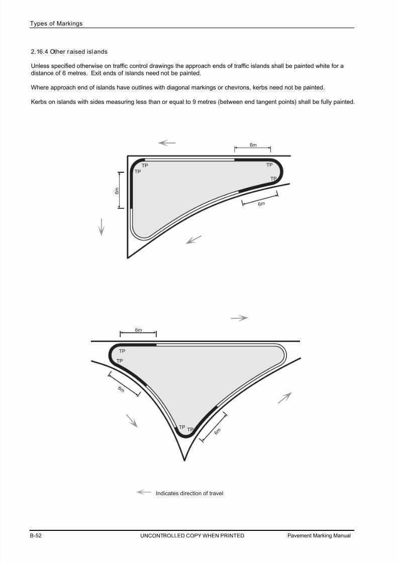
7/25/2019 Road Marking Guidelines
http://slidepdf.com/reader/full/road-marking-guidelines 64/159
Pavement Marking ManualB-52
Types of Markings
UNCONTROLLED COPY WHEN PRINTED
2.16.4 Other raised islands
Unless specified otherwise on traffic control drawings the approach ends of traffic islands shall be painted white for a
distance of 6 metres. Exit ends of islands need not be painted.
Where approach end of islands have outlines with diagonal markings or chevrons, kerbs need not be painted.
Kerbs on islands with sides measuring less than or equal to 9 metres (between end tangent points) shall be fully painted.
6 m
6m
TP
6 m
TPTP
TP
6m
TPTP
TP
TP
6 m
6 m
Indicates direction of travel

7/25/2019 Road Marking Guidelines
http://slidepdf.com/reader/full/road-marking-guidelines 65/159
Pavement Marking Manual B-53
Types of Markings
B
UNCONTROLLED COPY WHEN PRINTED
2.16.5 Pedestrian Refuges
Adjacent lane > 3.0m
Adjacent lane < 3.0m
as above but no outline, add line across opening as prolongation of kerb line.
2.16.6 Local Area Traffic Management (LATM)
For each length of kerb 24m or less, the entire kerb must be painted. Where the length of kerb is greater than 24m, at
least 6m of kerb from each end must be painted.
The kerb is painted the full length where the width of the adjacent lane is less than 3m. Otherwise the usual markingsfor medians apply.
It is not necessary to delineate the drainage channel formed by the existing kerb and kerb extensions, unless pedestriansafety is compromised or it forms part of a by-pass of the device for cyclists.
Typical installations of RRPMs at LATM treatments are shown in AS1742.13-2009.
100mm outline
painted kerb
for taper treatments
see Part C 3.4.2

7/25/2019 Road Marking Guidelines
http://slidepdf.com/reader/full/road-marking-guidelines 66/159
Pavement Markings ManualB-54
Types of Markings
UNCONTROLLED COPY WHEN PRINTED
2.18 LONGITUDINAL LINE STYLE TRANSITIONS
2.18.1 Dividing lines
Broken (standard) to enhanced
broken
Continuous to enhanced continuous
Enhanced continuous to standard
outline
2.17 BARRIER LINE INSTALLATION
2.17.1 Intersections
Gaps shall be provided in double two way barrier lines and shall generally be 10m wide and centrally placed at the
intersecting centre point of the side road.
Where barrier lines are required for vertical or horizontal alignment sight restrictions take precedence over standard rural
two lane, two way road intersection treatments.
2.17.2 Property accesses
Gaps should not generally be provided in double two way barrier lines. Leaving a gap allows a driver to legally enter and
leave the road as well as U-turns at a place where there may be a restricted sight distance due to horizontal or vertical
curves. A gap may only be provided where a survey determines that sufficient sight distance is available to safely allowall movements.
Where provided the gap shall generally be 5m. The gap may be increased at wider accesses or where the turning
vehicle envelope would otherwise cross the double two way barrier lines.
Centre line 200mm
100mm
12m
Centre line
100mm
200mm
Centre line 100mm
100mm
200mm
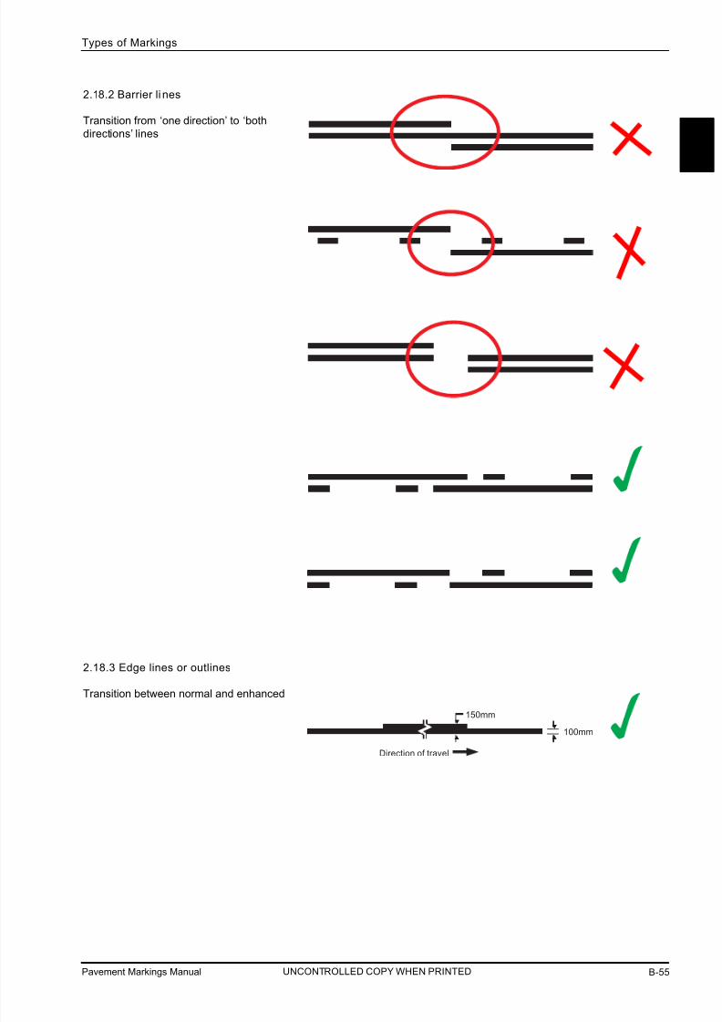
7/25/2019 Road Marking Guidelines
http://slidepdf.com/reader/full/road-marking-guidelines 67/159
Pavement Markings Manual B-55
Types of Markings
B
UNCONTROLLED COPY WHEN PRINTED
Direction of travel
100mm▼
▼
150mm▼
▼
2.18.2 Barrier li nes
Transition from ‘one direction’ to ‘both
directions’ lines
2.18.3 Edge lines or outlines
Transition between normal and enhanced

7/25/2019 Road Marking Guidelines
http://slidepdf.com/reader/full/road-marking-guidelines 68/159
Pavement Markings ManualB-56
Types of Markings
UNCONTROLLED COPY WHEN PRINTED
2.18.4 Edge l ine mis-match
A mis-match of the edge line road markings may result where a change of lane width occurs after sealing the road
shoulders, resealing works or road reconstruction. Where this occurs, a transition of the edge line between the new
and existing markings shall be made as indicated in the diagrams below.
transition edge linea minimum of 24m
standard edge lineon sealed shoulders
xisting surface
edge of seal
seal width <6.8m (no edge line)
work
new work
10d
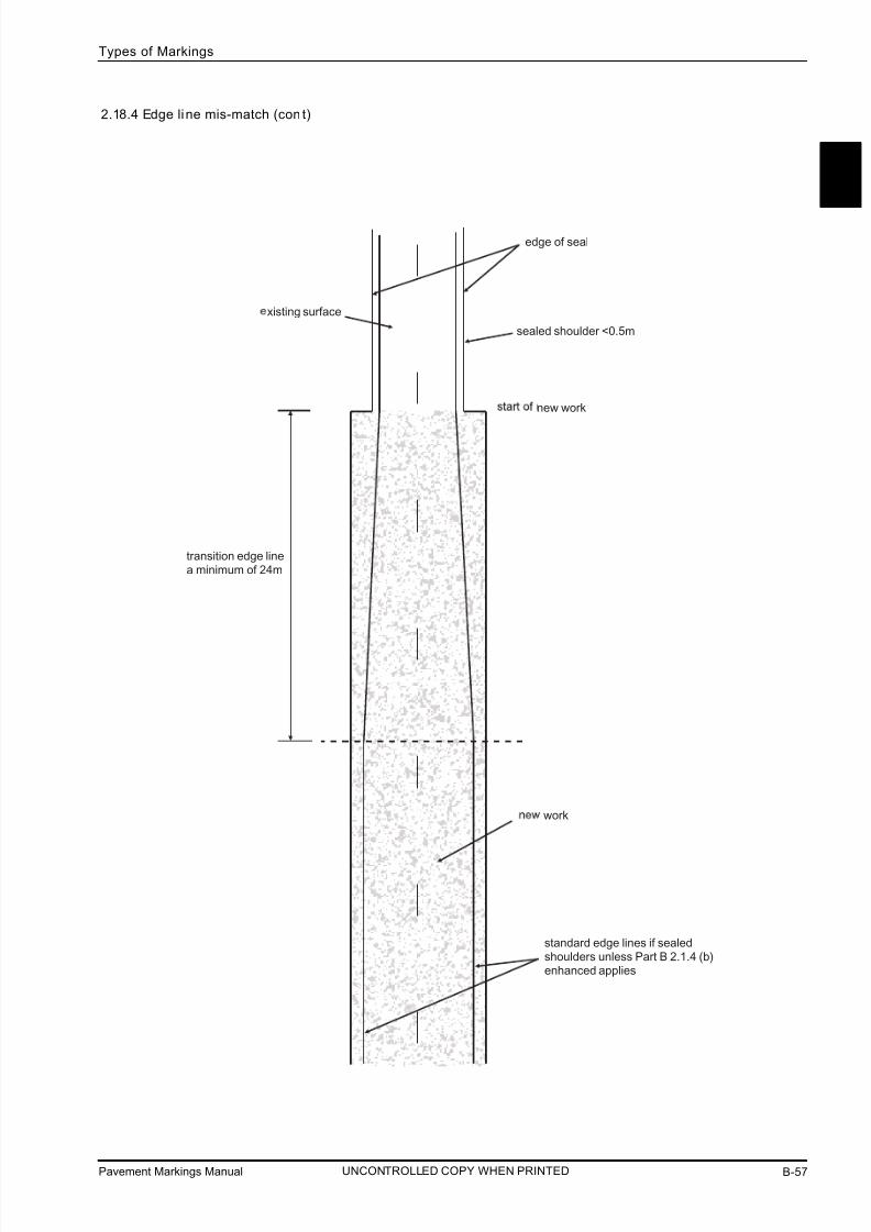
7/25/2019 Road Marking Guidelines
http://slidepdf.com/reader/full/road-marking-guidelines 69/159
Pavement Markings Manual B-57
Types of Markings
B
UNCONTROLLED COPY WHEN PRINTED
transition edge linea minimum of 24m
standard edge lines if sealedshoulders unless Part B 2.1.4 (b)enhanced applies
edge of seal
xisting surface
sealed shoulder <0.5m
work
new work
2.18.4 Edge line mis-match (con t)

7/25/2019 Road Marking Guidelines
http://slidepdf.com/reader/full/road-marking-guidelines 70/159
Pavement Markings Manual
Types of Markings
THIS PAGE HAS BEEN LEFT INTENTIONALLY BLANK
UNCONTROLLED COPY WHEN PRINTED

7/25/2019 Road Marking Guidelines
http://slidepdf.com/reader/full/road-marking-guidelines 71/159
Pavement Markings Manual C-1
Design Guide
PART CDESIGN GUIDE
1.0 SCOPE
This section contains the requirements for the correct and consistent use of pavement
markings on roads in South Australia.
It is intended that this section provides specific diagrammatic examples (i.e. not to scale or
proportion) of the application of markings and where necessary explain to the designer the
reasons why certain treatments are used. It also provides references to:
The Road Traffic Act
Australian Road Rules (ARR)
DPTI Code of Technical Requirements (the Code)
Australian Standards (AS)
Austroads Guide to Traffic Management (GTM)
Austroads Guide to Road Design (GRD)
Master Specifications (MS)
DPTI Traffic Engineering and Road Management Operational Instructions (OI)
All road authorities including their consultants and contractors are required to conform to this
manual.
NOTE:
Dimensioning Convention
Give Way, Stop lines and pavement messages are generally measuredfrom either the leading or trailing edge of the line or message.
x
lane lines
y
stop line
crosswalk line
All markings (longitudinal and transverse) are dimensioned centre
to centre, except for Give Way, Stop lines and pavement messages.
trailing edge
leading edge
All drawings are not to scale. The r eader shall use the dimensions
specified throughout the manual. DO NOT SCALE OFF DRAWINGS.
UNCONTROLLED COPY WHEN PRINTED
C

7/25/2019 Road Marking Guidelines
http://slidepdf.com/reader/full/road-marking-guidelines 72/159
2.0 TRAFFIC CONTROL DRAWINGS AND DESIGN LAYOUTS
2.1 LONGITUDINAL LINES
Longitudinal lines shall be shown on all traffic control drawings. This includes edge lines and outlines.
Dimensions to kerbs shall be to the kerb face. Dimensions to longitudinal lines (other than zigzag school zone markings )shall be to the centre of the line. Dimensions of barrier lines shall be to the centre of the combination of the two parallel
lines.
2.2 TRANSVERSE LINES
Transverse lines shall be shown on all traffic control drawings. Dimensions shall be clearly shown to either the leading or trailing face of all transverse lines, except pedestrian cross walk lines. Pedestrian crosswalk lines shall be dimensioned
to the centre of the line.
2.3 PARKING CONTROL LINES
2.3.1 Parking Control Edge lines
All parking control lines (where used) shall be shown on traffic control drawings.
Parking control edge lines shall be marked in a consistent alignment parallel to and approximately 400mm from the
kerb or edge of seal. This is to ensure that the line is not marked on the water table.
2.3.2 Parking Space Outli nes
Parking space outlines shall be shown and dimensioned on traffic control drawings.
2.4 DIAGONAL STRIPES AND CHEVRON MARKINGS
Diagonal stripes and chevron marking shall be shown on traffic control drawings.
2.5 ARROWS
All arrows shall be shown on traffic control drawings and may be dimensioned longitudinally. Arrows shall be located
centrally within the lane width as shown in Part B 2.6.
2.6 MESSAGES AND SYMBOLS
All messages and symbols shall be shown and the longitudinal spacing dimensioned longitudinally on traffic control
drawings.
Messages and symbols shall be located centrally within the lane such that a minimum of 150mm gap is maintained
between the edge of the message or symbol and the centre of any adjacent longitudinal line or to the edge of seal.
Spacing between letters to form commonly used words are shown in Part B 2.7.2.
Bicycle symbols shall be located approximately 100mm from the bicycle lane line adjacent to the traffic lane. Where thebicycle lane is less than 1.4 metres wide it will be necessary to reduce the width of the symbol. This will be achieved bymasking part of the rear wheel to preserve the 100mm gap between the edge of the symbol and the centre of lane line.
Symbols on paths shall be located centrally within the designated area of travel i.e. between the left edge of the path and
the separation line. Examples for both symbols and messages on paths is shown in Part C 3.19.
Pavement Marking ManualC-2
Design Guide
UNCONTROLLED COPY WHEN PRINTED

7/25/2019 Road Marking Guidelines
http://slidepdf.com/reader/full/road-marking-guidelines 73/159
Pavement Marking Manual C-3
Design Guide
References
ARR 132, 134, 208 (6)
AS1742.2 Section 5
GTM Part 10
OI 2.15
OI 2.27
OI 2.40
3.0 GENERAL TREATMENTS
General treatments are considered those that apply in all built up areas. These include
local residential roads, collector roads, arterial roads and expressway type roads in or near
cities and townships. They may include roads of any speed environment.
3.1 DIVIDING LINES
There is no traffic volume warrant for the provision of dividing lines on urban roads in South
Australia. It is important for designers to remember that the use of single continuous dividing
line prohibits certain crossing movements, including U turns, but does not prohibit entering or
leaving the road. U turns should generally not be restricted by the use of single continuouslines unless site distance is poor or special facilities have been provided to satisfy U turn
demand within the section of road.
Parking is also prohibited if the parked vehicle is less then 3 metres from the dividing line as
specified in ARR 208 (6).
Any assessment for the need for dividing lines should take the following into consideration:
All ‘arterial’ roads shall be provided with dividing lines in urban areas, and shall be
augmented with RRPMs.
All ‘collector’ roads should be provided with dividing lines.
Local roads may be provided with dividing lines. Installing dividing lines on narrow roads may
have implications for parking.
Where provided between major intersections dividing lines should be broken, and shall be
standard width for two lane roads and enhanced for multi lane roads.
Where provided on minor or local roads at intersections, short sections of continuous
dividing lines may be provided (see intersection examples in Part B 2.4.2, 2.4.3, 2.14.8,2.14.9 and Part C 3.13).
Double barrier lines, i.e. multiple lines consisting of combinations of broken and continuouslines or double continuous lines, are not used on urban roads.
Broken dividing lines on arterial roads continue through minor road intersections.
On any road, a break is provided in continuous dividing lines through intersections (see
Part B 2.4 for examples).
Dividing lines are not normally necessary on minor road approaches to major roads. However
there may be situations where such lines could provide additional guidance to road users.
Such cases include :
- Wide side roads
- Multi lane side roads- High volumes of right turn movements into and/or from minor road
Dividing lines should not be provided on minor road approaches where right turn and through
movements are prevented or prohibited from the minor road.
Dividing lines should always be provided on minor road approaches that have give way or stop
lines (also see Part C 3.13).
UNCONTROLLED COPY WHEN PRINTED
C
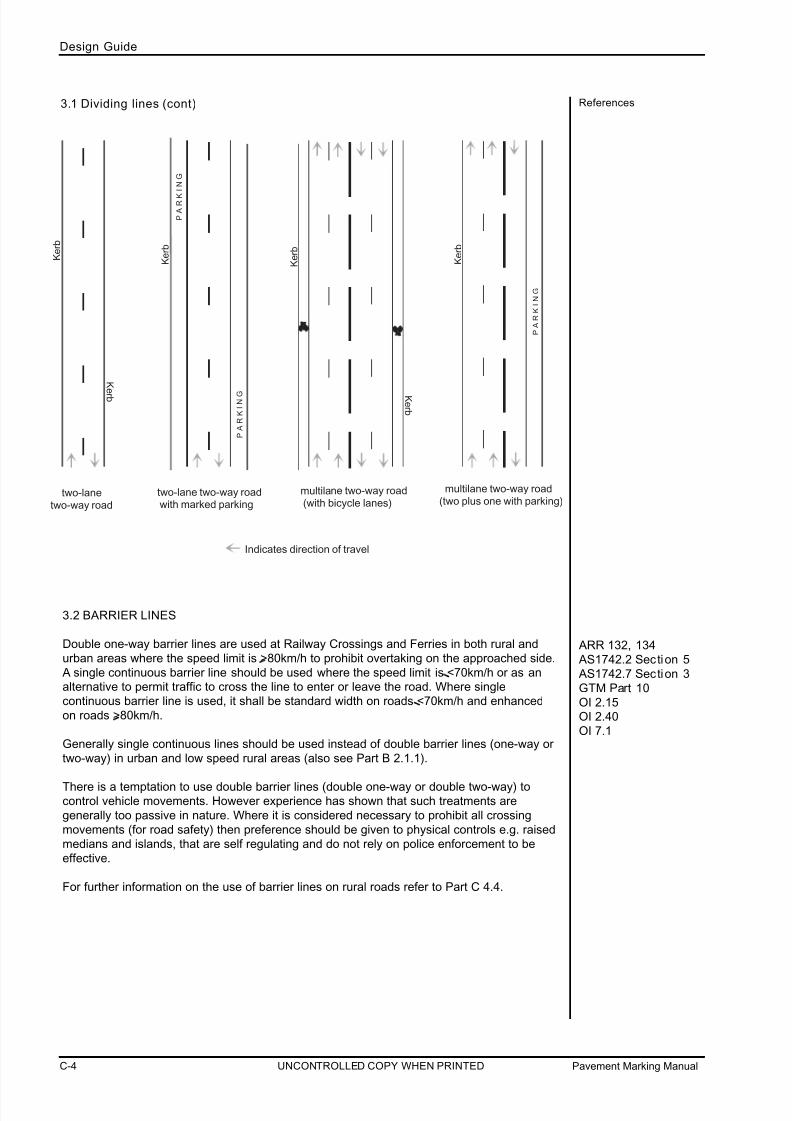
7/25/2019 Road Marking Guidelines
http://slidepdf.com/reader/full/road-marking-guidelines 74/159
Pavement Marking ManualC-4
Design Guide
UNCONTROLLED COPY WHEN PRINTED
References
ARR 132, 134
AS1742.2 Section 5
AS1742.7 Section 3
GTM Part 10
OI 2.15OI 2.40
OI 7.1
two-lanetwo-way road
two-lane two-way road with marked parking
multilane two-way road (with bicycle lanes)
multilane two-way road(two plus one with parking)
Indicates direction of travel
K e r b
K
e r b
P
A
R K
I N G
P
A
R K
I N G
P
A
R K
I N G
K e r b
K e r b
K e r b
K e r b
3.2 BARRIER LINES
Double one-way barrier lines are used at Railway Crossings and Ferries in both rural and
urban areas where the speed limit is >80km/h to prohibit overtaking on the approached side.
A single continuous barrier line should be used where the speed limit is <70km/h or as analternative to permit traffic to cross the line to enter or leave the road. Where single
continuous barrier line is used, it shall be standard width on roads <70km/h and enhanced
on roads >80km/h.
Generally single continuous lines should be used instead of double barrier lines (one-way or
two-way) in urban and low speed rural areas (also see Part B 2.1.1).
There is a temptation to use double barrier lines (double one-way or double two-way) tocontrol vehicle movements. However experience has shown that such treatments are
generally too passive in nature. Where it is considered necessary to prohibit all crossing
movements (for road safety) then preference should be given to physical controls e.g. raised
medians and islands, that are self regulating and do not rely on police enforcement to be
effective.
For further information on the use of barrier lines on rural roads refer to Part C 4.4.
3.1 Dividing lines (cont)
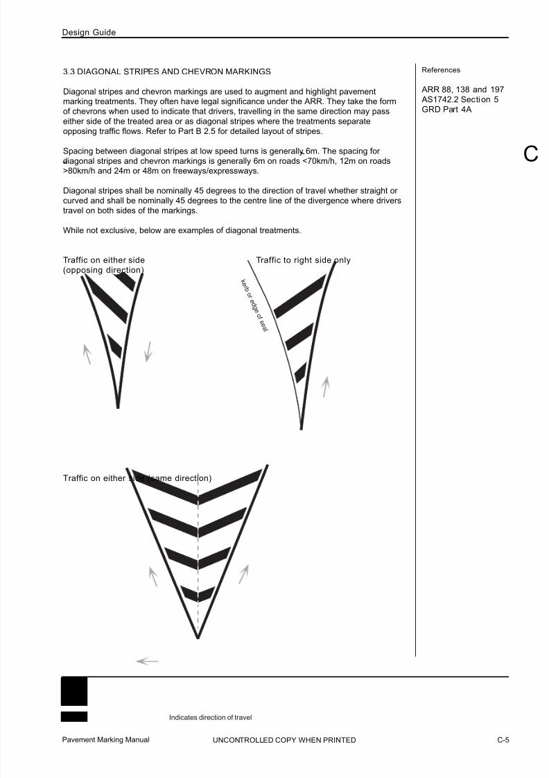
7/25/2019 Road Marking Guidelines
http://slidepdf.com/reader/full/road-marking-guidelines 75/159
Indicates direction of travel
k e r b o r e
d g e o f s
e a l
Pavement Marking Manual C-5
Design Guide
References
ARR 88, 138 and 197
AS1742.2 Section 5
GRD Part 4A
3.3 DIAGONAL STRIPES AND CHEVRON MARKINGS
Diagonal stripes and chevron markings are used to augment and highlight pavementmarking treatments. They often have legal significance under the ARR. They take the form
of chevrons when used to indicate that drivers, travelling in the same direction may pass
either side of the treated area or as diagonal stripes where the treatments separate
opposing traffic flows. Refer to Part B 2.5 for detailed layout of stripes.
Spacing between diagonal stripes at low speed turns is generally 6m. The spacing for
diagonal stripes and chevron markings is generally 6m on roads <70km/h, 12m on roads>80km/h and 24m or 48m on freeways/expressways.
Diagonal stripes shall be nominally 45 degrees to the direction of travel whether straight or
curved and shall be nominally 45 degrees to the centre line of the divergence where drivers
travel on both sides of the markings.
While not exclusive, below are examples of diagonal treatments.
Traffic on either side Traffic to right side only
(opposing direction)
Traffic on either side (same direction)
UNCONTROLLED COPY WHEN PRINTED
C

7/25/2019 Road Marking Guidelines
http://slidepdf.com/reader/full/road-marking-guidelines 76/159
References
ARR 138 (2)(a)
3.3.1 Corner Treatment
On curved alignments, where diagonal markings are not parallel, the spacing of the markings
shall be measured at the outline or edge line.
*Nominal spacing between stripes is 6 metres and nominally 45 degrees to the tangent alongthe edge line but may be varied. For rural treatments the spacing may be increased depending
on the radius of the curve. Where the section to be striped is short it is preferable to provide
stripes closer together (as close as 3 metres) to ensure the stripes provide the desired effect.
o
45
o
45
Indicates direction of travel
6m*
The use of diagonal stripes is discouraged on left turn treatments,where the left turn driver has priority i.e. AUL type treatment seePart B 2.14.9. Stripes are a passive treatment and in this locationare usually driven over regularly, requiring additional maintenance.They can also be a slip hazard with differential skid resistancebetween the painted area and the pavement.
nominally
nominally
nominally
edge line
Pavement Marking ManualC-6
Design Guide
UNCONTROLLED COPY WHEN PRINTED

7/25/2019 Road Marking Guidelines
http://slidepdf.com/reader/full/road-marking-guidelines 77/159
Pavement Marking Manual C-7
Design Guide
References
ARR 138
3.3.2 Flush medians
Flush medians (also known as painted islands) may separate lanes dividing opposing traffic
streams, while allowing access to and from the road or entrance to a turning lane.
It should be noted that unlike raised medians, flush medians do not provide physical control of
traffic movements nor do they have the advantages of being clearly visible, especially at night
and in wet weather.
Spacing between median breaks
Diagonal marking variations for median breaks
* Generally spacing between diagonal markings should be 12m. Spacing may be varied
between 10 - 15m to suit median lengths. Spacing must be consistent along entire length
of each median section. Although it is preferable to provide at least 2 diagonal markings
in short lengths, one marking may be used in cases of very short lengths.
*12m
UNCONTROLLED COPY WHEN PRINTED
C
*15m
45m
widest
point
taper point
Indicates direction of travel
w idest
point
*15m
widest
point
>10m
but <20m
widest
point
>10m
widest point

7/25/2019 Road Marking Guidelines
http://slidepdf.com/reader/full/road-marking-guidelines 78/159
References
ARR 62, 69 (2A) and72 (4)
3.3.3 Corner islands
The use of very small corner islands (less than 3m sides) should be avoided. Such islands
cause confusion to drivers regarding give way responsibilities when turning at intersections.
Chevrons and diagonal stripes may be used between the outline and the kerb of a raised
island where better turning control is required. However, they should only be augmented with
diagonal stripes where the distance between the kerb and outline is greater than 1.0m.
Flush Corner Island
Corner Islands both flush and raised for left turning vehicles should be augmented withchevron markings for the guidance of both left turn and through vehicles. The treatment also
clearly define the differences in the ARR between turning movement priorities at intersections.
Raised Corner Island
3m
3m
3m
3m 3m3m>1m
<1m
Indicates direction of travel
<3m
<3m
>3m - <12m
>3m - <12m1m
1m
Pavement Marking ManualC-8
Design Guide
UNCONTROLLED COPY WHEN PRINTED

7/25/2019 Road Marking Guidelines
http://slidepdf.com/reader/full/road-marking-guidelines 79/159
Pavement Marking Manual C-9
Design Guide
References
ARR 138 (2) (a)
3.3.4 High angle treatment
Diagonal stripes adjacent to kerbs at left turn treatments may be placed to guide standard
design vehicles through left turns.
Vehicles such as semi-trailers are permitted to turn over diagonal stripes to complete turns.
Diagonal markings may be supplemented with pavement bars to promote lane compliance.
Special purpose lanes and corner island treatments, adjacent to motor vehicle through lanes.
k e r b
UNCONTROLLED COPY WHEN PRINTED
C

7/25/2019 Road Marking Guidelines
http://slidepdf.com/reader/full/road-marking-guidelines 80/159
References
GRD Part 4A
GRD Part 3 Section 9
ARR 135, 137, 138 AS1742.2 Section 2
GRD Part 3 Section 9
3.4 DIVERGE AND MERGE TAPER TREATMENTS
For overtaking lanes see Part C 4.9 and for diverges at kerb extensions see Part C 3.12, the
approaches to intersections e.g. CHR type treatments, see Austroads Guide to Road Design
Part 4A.
3.4.1 Diverge taper treatments
It is often necessary to move traffic laterally across a section of road without merging lanes.
Examples include divergence of lanes to avoid pedestrian refuges, on street parking areas
and at the start of median sections.
It is preferable to provide as long a divergence length as possible, especially where two or more adjacent lanes must diverge and also if visibility to the island is reduced by vertical or
horizontal alignment. The following diverge calculation provides a minimum length. However,
experience has shown that greater lengths should be provided whenever possible. For
example, extra taper length is important for pedestrian refuge situations to provide additional
protection for pedestrians and to avoid damage to signs and pedestrian hand rails (see Part C
3.20.1).
Undivided to divided
The following example may be applied to locations where road widening has been undertaken
predominantly on one side of the road.
W
Td = V W
3.6S
painted median is preceded by a
enhanced single barrier line extending
for 30m minimum (this may be double
one-way or double two-way barrier line
on rural roads)
Td = diverge length (m) V = design speed or speed limit (km\h) W = lateral movement (m) S = rate of lateral movement (m/s) (0.6 m/s for multi-lane roads otherwise 1.0m/s)
A longer transistion taper is required for multi-lane
roads to ensure drivers in all lanes understand the
need to diverge together.
Pavement Marking ManualC-10
Design Guide
UNCONTROLLED COPY WHEN PRINTED

7/25/2019 Road Marking Guidelines
http://slidepdf.com/reader/full/road-marking-guidelines 81/159
Pavement Marking Manual C-11
Design Guide
References
ARR 149
AS1742.2 Section 4
GRD Part 4A
AS1742.2 Section 5.6
3.4.2 Merge taper treatments (lane drop situations)
‘Zip merge’, is the preferred merge treatment in
urban areas with a speed limit of less than 80km/h
This is a minimum merge taper length. However,
experience has shown that greater lengths should
be provided, to assist drivers undertake the‘zip merge’.
Tm = Merge length
V = Design speed or speed limit *(km/h)
Y = Lateral movement (m)
S = Rate of lateral movement
for a merge, S = 0.6m/sec
for a 3.5m lane width, Tm = 70 x 3.5
3.6 x 0.6 = 110m
Lane termination is required for areas where the
road is restricted.
Design Speedor Speed L imi t (km/h)* x
< 60 36m
< 80 48m
*whichever is higher
‘Zip merges’ are not to be used on roads with a
speed limit of 80 km/h or greater.
3.5 RAISED PAVEMENT MARKERS
Painted lines, stripes and chevrons may be augmented with retroreflective raised pavementmarkers (RRPMs) to improve their visual properties (see Part B 2.14).
As a minimum on arterial roads, RRPMs shall be provided on all dividing lines in urban areas
and should be provided on dividing lines in rural areas. RRPMs should also be provided on
lane lines, special purpose lane lines and flush island outlines.
RRPMs enhance longitudinal lines to such an extent that they discourage crossingmovements. For this reason RRPMs shall not be used on continuity lines except in
circumstances shown (see Part C 3.5.1).
RRPMs may be used on collector and local roads if additional delineation treatment is
considered necessary.
Standard spacing is 12m on lit and 24m on unlit roads.
For the use of non-reflective pavement markers through intersections, refer to Part C 3.17.6.
lane widths
3.5m
m e d i an
note :
no continuity
lines
Tm = V Y
3.6 S
x
direction
of travel
Y
kerb, edge of seal
or edge line
UNCONTROLLED COPY WHEN PRINTED
C

7/25/2019 Road Marking Guidelines
http://slidepdf.com/reader/full/road-marking-guidelines 82/159
References3.5.1.Continuity lines
Generally RRPMs are not required on continuity lines. However, in some rare cases they maybe required to provide guidance:
- on tapers where traffic is required to deviate from their path eg. trapped lane situation.
- on long lengths of curvilinear continuity lines.
Note:
- RRPMs shall not be used on continuity lines in merging situations.- Where used, spacing shall be generally the same as that applied to lane lines i.e 12m
on lit and 24m on unlit roads.
3.5.2 Bicycle lanes
The provision of RRPMs can be hazardous to cyclists when placed adjacent bicycle lane lines.This is particularly the case for part-time bicycle lanes when cyclists are required to ride
around parked cars outside bicycle lane operating times. Therefore it is recommended that
RRPMs not be located adjacent to or near part-time bicycle lane lines. It may also be
appropriate to not install RRPMs on full-time bicycle lanes in areas where cyclists are required
to ride around buses and other vehicles legitimately stopped on the road.
12m
where RRPMs on continuity lines are used, it must
be shown / indicated on the design drawings.
Pavement Marking ManualC-12
Design Guide
UNCONTROLLED COPY WHEN PRINTED

7/25/2019 Road Marking Guidelines
http://slidepdf.com/reader/full/road-marking-guidelines 83/159
Pavement Marking Manual C-13
Design Guide
References
ARR 146, 147, 148
AS1742.2 Section 5
3.6 LANE LINES
Lane lines divide two or more lines of traffic travelling in the same direction and shall be
provided on roads where traffic is expected to travel in more than one lane.
When re-allocating the carriageway width to allow cyclists and drivers to travel side by side
within the wide kerbside lane, the minimum lane width shall be 3.7m.
Lane lines are normally standard broken. However, continuous lane lines may be required
between exclusive through and exclusive turn lanes on approaches to intersections (see PartC 3.7). They may also be used to restrict lane changing mid-block.
Lane lines should be continued through minor road intersections.
At a lane drop, the lane line should cease before the taper commences. This distance is
shown in the table in Part C 3.4.2.
For lane lines on the approach to signalised intersections see Part C 3.17.5.
For the use of continuity lines as lane lines (including the length of continuous line) see
Part C 3.7.
continuity linessee Part C 2.7
lane dropsee Part C 2.4.2
length of unbroken lane line see Part C 2.7
5 m
7 .5 m
UNCONTROLLED COPY WHEN PRINTED
C

7/25/2019 Road Marking Guidelines
http://slidepdf.com/reader/full/road-marking-guidelines 84/159
References
ARR Part 9
AS1742.2 Section 5
GTM Part 6
GTM Part 10
3.6.1 Roundabouts
Lane lines on the approach to a multilane roundabout are positioned as they would be for
other intersections. The lane lines within the circulating lanes and leading out of a
roundabout, known as special purpose lines, provide added guidance through the curves
while negotiating within and exiting the roundabout. Lane lines must be curved where
necessary to ensure this guidance is further enhanced.
The exit line extends from within the circulatingpath and continues into the exit road.
Starting position for exit line, see inset for each exit line around the roundabout.
Additional two exit linesshould be provided after the exit.
exit area
Exit line placement
Pavement Marking ManualC-14
Design Guide
UNCONTROLLED COPY WHEN PRINTED

7/25/2019 Road Marking Guidelines
http://slidepdf.com/reader/full/road-marking-guidelines 85/159
Pavement Marking Manual C-15
Design Guide
ReferencesMulti-lane roundabout with two single lane approaches
and two sing le lane exits
Multi-lane roundabout wi th two lane approaches and twolane exits
UNCONTROLLED COPY WHEN PRINTED
C

7/25/2019 Road Marking Guidelines
http://slidepdf.com/reader/full/road-marking-guidelines 86/159

7/25/2019 Road Marking Guidelines
http://slidepdf.com/reader/full/road-marking-guidelines 87/159
Pavement Marking Manual C-17
Design Guide
References
ARR 77, 183, 187, 195
ker b
m e d i a n ( o r o t h e r d i v i d i n g t r e a t m e n t )
c a r p a r k
c a r p
a r k
b u s s t o p
2 0
m
kerb
Standard
continuous line
i n d e n t e d b u s s t o p
1 0 m
bus stop
sign
Standar d
continuous line
3.6.2 Bicycle lanes adjacent to bus stops
NOTE:
For bus stop design requirements, refer to GD800 (www.dpti.sa.gov.au/standards/roads-all)
UNCONTROLLED COPY WHEN PRINTED
C
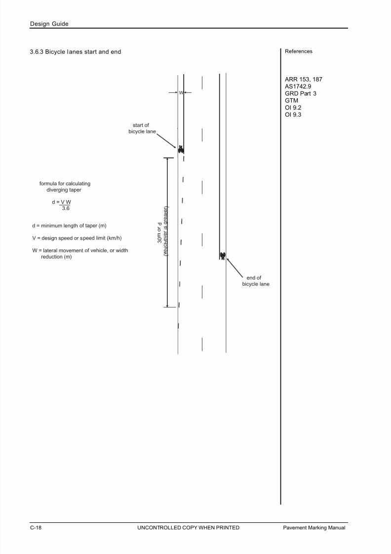
7/25/2019 Road Marking Guidelines
http://slidepdf.com/reader/full/road-marking-guidelines 88/159
References
ARR 153, 187
AS1742.9
GRD Part 3
GTM
OI 9.2OI 9.3
3.6.3 Bicycle lanes start and end
start of
bicycle lane
end of bicycle lane
W
3 0 m
o r d
( w h i c h e v e r i s g r e a t e r )
formula for calculating
diverging taper
d = V W 3.6
d = minimum length of taper (m)
V = design speed or speed limit (km/h)
W = lateral movement of vehicle, or width
r eduction (m)
Pavement Marking ManualC-18
Design Guide
UNCONTROLLED COPY WHEN PRINTED

7/25/2019 Road Marking Guidelines
http://slidepdf.com/reader/full/road-marking-guidelines 89/159
Pavement Marking Manual C-19
Design Guide
References
ARR 147, 148
3.7 CONTINUITY LINES
Continuity lines generally provide longitudinal ‘continuity’ to traffic along lengths of road where
lane lines or other longitudinal lines either cannot or should not be provided. They are used to
substitute lane, dividing or edge lines where it is intended that the line be crossed by traffic
turning or lane changing.
Where they are used in lieu of a lane or dividing line it is important to remember that theymay continue to have the same legal effect in regard to traffic movements.
Examples of continuity lines include :
To provide continuity at very wide straight openings across side roads or other entry and
exit points along a road or across those openings that are subject to significant vertical
or horizontal changes. Continuity lines should only be provided for such situations where
it is likely that through traffic would otherwise loose continuity of travel (see Part C 3.7.3 and
3.15 for example).
At the start and end of auxiliary and special purpose lanes to indicate the section of road
that should be crossed to access or exit the auxiliary lane. Examples include:
- Acceleration and deceleration lanes (see below)
- Bus lanes (Part C 3.22.2 - 4)- Bicycle lanes (Part C 3.6.3)
- Overtaking lanes (Part C 4.9)
- Slow vehicle turnouts (Part C 4.10)
Across side roads and other sections of road to indicate the continuance of bicycle lanes.
Across median openings where the median is greater than 2 metres in width.
3.7.1 Left and right turn storage / deceleration / acceleration lanes
x kerb or edge of bitumen
A
x
A
kerb or edge of bitumen
A x
<72m 0m (all continuity line)
72m - 120m 12m continuous line120m - 180m 24m continuous line
>180m 36m continuous line
UNCONTROLLED COPY WHEN PRINTED
C

7/25/2019 Road Marking Guidelines
http://slidepdf.com/reader/full/road-marking-guidelines 90/159
References3.7.2 Bicycle lane continuity lines
k e r b
turning vehicle envelope
Note:
1. Check turning vehicle envelope forstandard design vehicle.
2. Bicycle lane continuity lines to extend across turning vehicle envelope.
3. Bicycle logo not to be placed within bicycle lane continuity lines.
k e r b
P A R K I N G
P A R K I N G
k e r b k
e r b
Pavement Marking ManualC-20
Design Guide
UNCONTROLLED COPY WHEN PRINTED

7/25/2019 Road Marking Guidelines
http://slidepdf.com/reader/full/road-marking-guidelines 91/159
Pavement Marking Manual C-21
Design Guide
References
UNCONTROLLED COPY WHEN PRINTED
C
3.7.3 Side road continuity lines
- Side roads >12m wide
- Continuity line may be used across
narrower side roads if there is a loss of continuity of edge line due to the
road geometry.- Edge line and barrier / dividing line
type will vary.
Notes

7/25/2019 Road Marking Guidelines
http://slidepdf.com/reader/full/road-marking-guidelines 92/159
References3.7.3 Side road continuity lines (cont)
CREST VERTICAL CURVE
5 . 0
0
5 . 0
0
1 0 . 0
0
1 5 . 0
0
2 0 . 0
0
2 5 . 0
0
3 0 . 0
0
3 5 . 0
0
4 0 . 0
0
4 5 . 0
0
5 0 . 0
0
5 5 . 0
0
1 0 . 0
0
1 5 . 0
0
2 0 . 0
0
2 5 . 0
0
3 0 . 0
0
3 5 . 0
0
4 0 . 0
0
4 5 . 0
0
5 0 . 0
0
5 5 . 0
0
Pavement Marking ManualC-22
Design Guide
UNCONTROLLED COPY WHEN PRINTED

7/25/2019 Road Marking Guidelines
http://slidepdf.com/reader/full/road-marking-guidelines 93/159
Pavement Marking Manual C-23
Design Guide
UNCONTROLLED COPY WHEN PRINTED
C
References3.8 PAVEMENT ARROWS
3.8.1 Unsignalised intersections
(a) Auxi liary Left Turn (AUL)
TP
6m
15m-30m
15m-30m
first arrow placedat full lane width
these distances
must be equal
(b) Channelised Right Turn (CHR)
7.5m
5m
6m
15m-30m
15m-30m
first arrow placedat full lane width
these distances
must be equal

7/25/2019 Road Marking Guidelines
http://slidepdf.com/reader/full/road-marking-guidelines 94/159
References3.8.1 Unsignalised intersections (cont)
(c) Channelised Left Turn (CHL)
TP
6m
15m-30m
15m-30m
first arrow placed
at full lane width
these distances
must be equal
Pavement Marking ManualC-24
Design Guide
UNCONTROLLED COPY WHEN PRINTED

7/25/2019 Road Marking Guidelines
http://slidepdf.com/reader/full/road-marking-guidelines 95/159
Pavement Marking Manual C-25
Design Guide
UNCONTROLLED COPY WHEN PRINTED
C
References3.8.2 Mid-block (includes local road and property access)
7.5m5m6m15m-30mfirst arrow placed
at full lane width
TP
25m minimum for 2 turn arrows*
kerb or edge line
Note: For longer turning lanes, see arrow
placement for AUL, CHR & CHL
treatments on the previous pages
* If lane is <25m but >12m then place one arrow
mid-way along lane. If lane is <12m then no arrows.
7.5m 5m >12m*
single arrow placed
mid-way along lane
(minus taper)
kerb or edge line
7.5m5m<12m*
no arrow
25m minimum for 2 turn arrows*
6m 15m-30m
kerb or edge line
first arrow placed
at full lane width
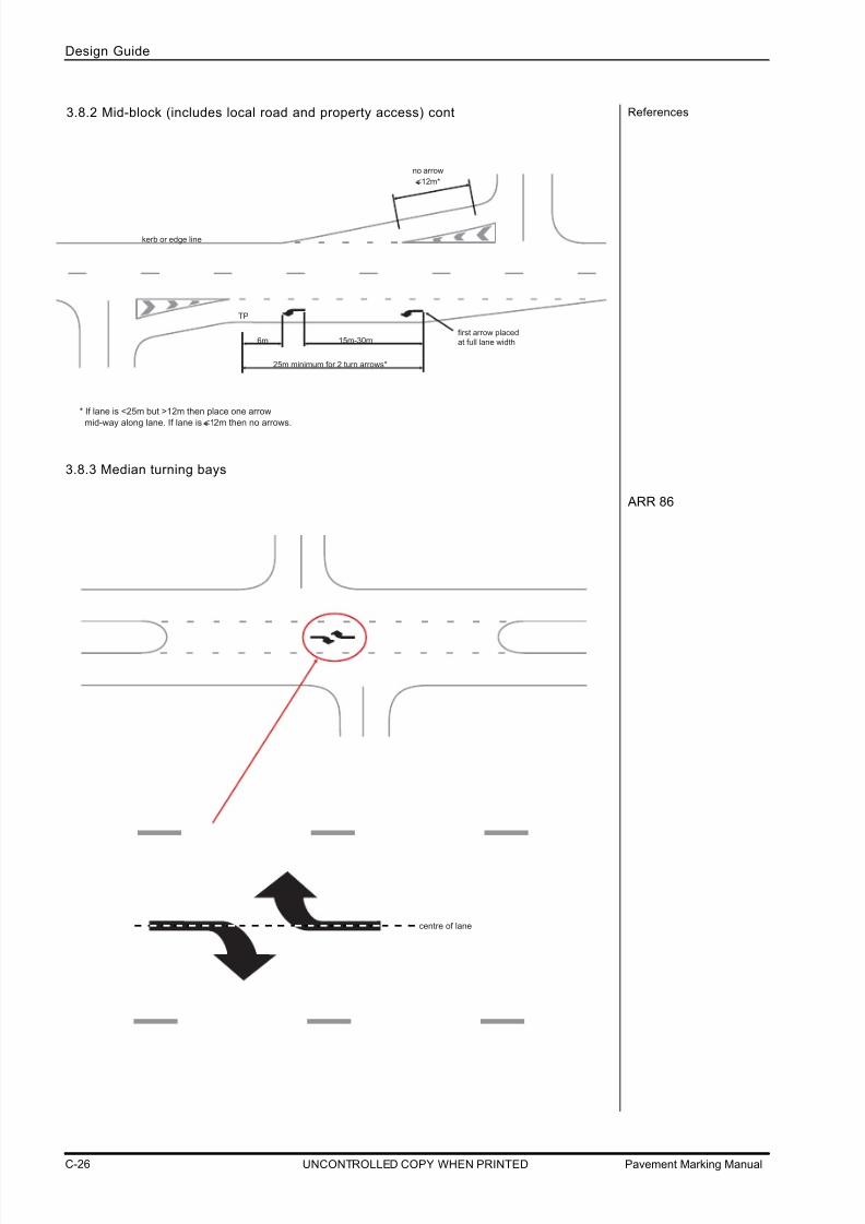
7/25/2019 Road Marking Guidelines
http://slidepdf.com/reader/full/road-marking-guidelines 96/159
References
ARR 86
3.8.3 Median turning bays
TP
25m minimum for 2 turn arrows*
6m 15m-30mfirst arrow placed
at full lane width
* If lane is <25m but >12m then place one arrow
mid-way along lane. If lane is <12m then no arrows.
<12m*
no arrow
kerb or edge line
3.8.2 Mid-block (includes local road and property access) cont
centre of lane
Pavement Marking ManualC-26
Design Guide
UNCONTROLLED COPY WHEN PRINTED
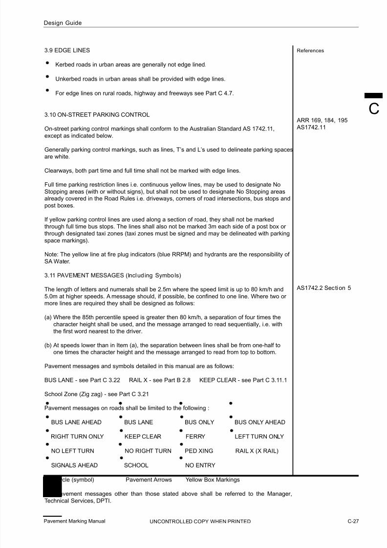
7/25/2019 Road Marking Guidelines
http://slidepdf.com/reader/full/road-marking-guidelines 97/159
Pavement Marking Manual C-27
Design Guide
UNCONTROLLED COPY WHEN PRINTED
C
References
ARR 169, 184, 195
AS1742.11
AS1742.2 Section 5
3.9 EDGE LINES
Kerbed roads in urban areas are generally not edge lined.
Unkerbed roads in urban areas shall be provided with edge lines.
For edge lines on rural roads, highway and freeways see Part C 4.7.
3.10 ON-STREET PARKING CONTROL
On-street parking control markings shall conform to the Australian Standard AS 1742.11,
except as indicated below.
Generally parking control markings, such as lines, T’s and L’s used to delineate parking spaces
are white.
Clearways, both part time and full time shall not be marked with edge lines.
Full time parking restriction lines i.e. continuous yellow lines, may be used to designate No
Stopping areas (with or without signs), but shall not be used to designate No Stopping areasalready covered in the Road Rules i.e. driveways, corners of road intersections, bus stops and
post boxes.
If yellow parking control lines are used along a section of road, they shall not be marked
through full time bus stops. The lines shall also not be marked 3m each side of a post box or
through designated taxi zones (taxi zones must be signed and may be delineated with parking
space markings).
Note: The yellow line at fire plug indicators (blue RRPM) and hydrants are the responsibility of
SA Water.
3.11 PAVEMENT MESSAGES (Including Symbols)
The length of letters and numerals shall be 2.5m where the speed limit is up to 80 km/h and5.0m at higher speeds. A message should, if possible, be confined to one line. Where two or more lines are required they shall be designed as follows:
(a) Where the 85th percentile speed is greater then 80 km/h, a separation of four times the
character height shall be used, and the message arranged to read sequentially, i.e. with
the first word nearest to the driver.
(b) At speeds lower than in Item (a), the separation between lines shall be from one-half toone times the character height and the message arranged to read from top to bottom.
Pavement messages and symbols detailed in this manual are as follows:
BUS LANE - see Part C 3.22 RAIL X - see Part B 2.8 KEEP CLEAR - see Part C 3.11.1
School Zone (Zig zag) - see Part C 3.21
Pavement messages on roads shall be limited to the following :
BUS LANE AHEAD BUS LANE BUS ONLY BUS ONLY AHEAD
RIGHT TURN ONLY KEEP CLEAR FERRY LEFT TURN ONLY
NO LEFT TURN NO RIGHT TURN PED XING RAIL X (X RAIL)
SIGNALS AHEAD SCHOOL NO ENTRY
Bicycle (symbol) Pavement Arrows Yellow Box Markings
For pavement messages other than those stated above shall be referred to the Manager,
Technical Services, DPTI.

7/25/2019 Road Marking Guidelines
http://slidepdf.com/reader/full/road-marking-guidelines 98/159
References
AS1428.1
AS1742.9
OI 2.12
ARR 96
AS1742.2 Section5OI 2.23
Pavement messages for road related areas shall be limited to the following:
Bicycle (symbol) Access (symbol) Bicycle Prohibited (symbol)
Path Arrows Pedestrian (symbol) Skater Prohibited (symbol)
3.11.1 Keep c lear
The keep clear pavement message shall only be used in accordance with Operational
Instruction 2.23 KEEP CLEAR Pavement Markings.
Keep clear pavement markings shall consist of the words “KEEP CLEAR” and:
Be positioned wholly within a single lane where possible.
Shall have 2.5m letter height with 2.5m spacing between words.
Shall have a letter style as shown in AS1742.2 and Part B 2.7.2.
Where two or more lanes in the same direction are to be marked with KEEP CLEAR, the
message may be staggered at wide side roads or driveways.
The spacing of the letters in the word CLEAR may be reduced to fit the whole word into
the lane.
If the lane widths in the same direction are, on average, less than 3.3m wide then a single
KEEP CLEAR message may be used across 2 lanes or 2 messages across 3 lanes.
Single lane
Multi-lane (preferred)
2.5m
2.5m
2.5m
2.5m
2.5m
2.5m
150mm line, positioned to the limitsof the required keep clear area. e.g.in line with side road kerbs.
Note: a single message coveringtwo lanes may be adequate.The words may be spaced
wider to suit.
Pavement Marking ManualC-28
Design Guide
UNCONTROLLED COPY WHEN PRINTED

7/25/2019 Road Marking Guidelines
http://slidepdf.com/reader/full/road-marking-guidelines 99/159
Pavement Marking Manual C-29
Design Guide
UNCONTROLLED COPY WHEN PRINTED
C
References3.11.2 Speed limits
Speed limit pavement messages shall not be used in South Australia.
3.11.3 Other messages
Where it is desired to use other pavement messages, the matter shall be referred to theManager, Technical Services, DPTI.
3.12 KERB EXTENSION MARKINGS
Kerb extensions are used to reduce road widths, especially in pedestrian crossing locations.
As the name suggests, kerb extensions should preferably consist of raised areas bordered
by semi mountable median type kerbing. However, they may also consist of pavement
markings designated by outline markings with diagonal stripes, and pavement bars and/or
RRPMs.
Kerb extensions may also be used to physically control the movement of vehicles, such as a
traffic divergence on a road section or to create a high angle entry to the main road.
Note: Diagonal stripes should be placed at 6m spacing on the divergence
taper section and then at 12m spacing for long parallel sections
up to 200m. For sections longer than 200m where diagonal stripes
are considered necessary they may be spaced at up to 24m in urban
areas and up to 48m in high speed rural areas.
taper length determined in
accordance with Part C 3.4
raised
kerb or edge of seal
Indicates direction of travel

7/25/2019 Road Marking Guidelines
http://slidepdf.com/reader/full/road-marking-guidelines 100/159
References
ARR 195
10m
20m
Busstop
0
10m
6m
Standardcontinuous line
may be supplemented
with pavement bars for
positive lane control
refer to Part B 2.13
3m
3m
No painted kerb extension
Painted kerbextension
nominally 10m
Painted kerb extensions
Pavement Marking ManualC-30
Design Guide
UNCONTROLLED COPY WHEN PRINTED

7/25/2019 Road Marking Guidelines
http://slidepdf.com/reader/full/road-marking-guidelines 101/159
Pavement Marking Manual C-31
Design Guide
UNCONTROLLED COPY WHEN PRINTED
C
References
ARR 170
3.14 GIVE WAY AND STOP LINE MARKINGS
width = 450mm (<80km/h)width = 600mm (>80km/h)
Note: Examples shown apply for both GIVE WAY and STOP locations.
kerb
x placement of give way line may have to bef urther in advance of the roundabout to allowf or the wider swept path of some lar ger vehiclestravelling ar ound the roundabout.
x =
typical no special
tur n requir ements
typical no specialturn r equirements
3.13 STANDARD INTERSECTIONS (Local Urban Roads)
Local or minor roads need not to be line marked. However, where they are, it is preferred to
provide a single dividing line to the extent of the limit of the No Stopping restriction from the
intersection (only) on the road with priority.
The controlled road approaches i.e. the road under Give Way or Stop sign control must be
provided with a give way or stop line. The provision of a dividing line from the give way or
stop line is preferred.
The dividing line would not normally extend beyond 10m from the kerb alignment of the
intersecting road. This length of line matches the road rule which prohibits stopping within10m of an intersecting road.
10m
minimum
kerb
dividing line
10m
minimum
5m 5m

7/25/2019 Road Marking Guidelines
http://slidepdf.com/reader/full/road-marking-guidelines 102/159
References
nominally 10m
kerb or edge of seal
kerb or edge line
or edge of seal
edge lineedge line
ker b or edge lineor edge of seal
kerb or edge line
or edge of seal
ker b or edge lineor edge of seal
Pavement Marking ManualC-32
Design Guide
UNCONTROLLED COPY WHEN PRINTED
3.14 GIVE WAY AND STOP LINE MARKINGS (cont)

7/25/2019 Road Marking Guidelines
http://slidepdf.com/reader/full/road-marking-guidelines 103/159
Pavement Marking Manual C-33
Design Guide
UNCONTROLLED COPY WHEN PRINTED
C
References3.15 CHANGED PRIORITY
Changed priorit y intersection
5 m
7 .5 m
enhanced
kerb or
edgeline

7/25/2019 Road Marking Guidelines
http://slidepdf.com/reader/full/road-marking-guidelines 104/159
References
The Code Section 7 AS1742.2 Section 2
AS1742.2 Section 5
ARR Part 9
3.16 ROUNDABOUTS
Give Way l ines
All roundabouts shall be provided with give way lines at the point drivers are expected to
‘hold’ to give way before entering the circulating lane(s). To determine the location of the
give way line it is important to consider sight distance to approaching vehicles from the right
while ensuring that the holding vehicle is not placed within the turning path of vehicles
travelling within the circulating lane(s), see Part C 3.14.
Special purpose and lane lines
Refer to Part C 3.6.1.
Note: Spiral lane line markings i.e. where additional lanes are created within a
roundabout shall not be used in SA without the authorisation of Manager,
Technical Services, DPTI.
Pavement arrows
Pavement arrows, while not used on single lane roundabouts, shall be used on anyapproach to the roundabout which has more than one lane. See part C 3.6.1 for examples.
Splitter islands
Splitter islands, raised or flush, shall be provided on each approach. A standard single
continuous barrier line should be marked on the approach to a splitter island.
Painted kerb and outlines
All roundabouts, splitter islands and kerb extensions shall be painted and may be outlined.For semi-mountable central islands and splitter islands refer to Part B 2.16.
kerbextension
3.16.1 Single lane roundabout
Pavement Marking ManualC-34
Design Guide
UNCONTROLLED COPY WHEN PRINTED

7/25/2019 Road Marking Guidelines
http://slidepdf.com/reader/full/road-marking-guidelines 105/159
Pavement Marking Manual
Design Guide
C-35
C
UNCONTROLLED COPY WHEN PRINTED
References3.16.2 Multi-lane T-intersection roundabout
3.16.3 Bicycle lane approach and exit to a single lane roundabout
locate start of bicycle lane outside turning envelop
design vehicletur ning template
locate end of bicycle lane
outside turning envelop

7/25/2019 Road Marking Guidelines
http://slidepdf.com/reader/full/road-marking-guidelines 106/159
References3.17 SIGNALISED INTERSECTIONS
Signalised intersection treatment index
52
6
1
4
3
1 Pedestrian cros swalk lines (page C-37)
3 Turn lines (page C-39)
4 Pavement arrows (page C-40)
6 Non-reflect ive raised (page C-45)
2 Stop lines (page C-38) 5 Lane lines (page C-44)
pavement markers
Pavement Marking ManualC-36
Design Guide
UNCONTROLLED COPY WHEN PRINTED
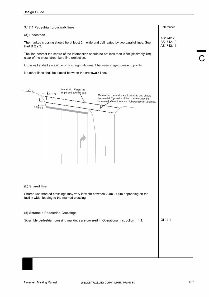
7/25/2019 Road Marking Guidelines
http://slidepdf.com/reader/full/road-marking-guidelines 107/159
Pavement Marking Manual C-37
Design Guide
C
UNCONTROLLED COPY WHEN PRINTED
References
AS1742.2 AS1742.10
AS1742.14
OI 14.1
3.17.1 Pedestrian crosswalk lines
(a) Pedestrian
The marked crossing should be at least 2m wide and delineated by two parallel lines. SeePart B 2.2.3.
The line nearest the centre of the intersection should be not less then 0.6m (desirably 1m)
clear of the cross street kerb line projection.
Crosswalks shall always be on a straight alignment between staged crossing points.
No other lines shall be placed between the crosswalk lines.
(b) Shared Use
Shared use marked crossings may vary in width between 2.4m - 4.0m depending on the
facility width leading to the marked crossing.
(c) Scramble Pedestrian Crossings
Scramble pedestrian crossing markings are covered in Operational Instruction 14.1.
0.6 - 1m
line width 150mm,1mstr ipe and 300mm gap
kerb
1.2 m mi n
Gener ally cr osswalks ar e 2.4m wide and shouldbe parallel. The width of the cr osswalkmay beincr eased where ther e are high pedestrian volumes.

7/25/2019 Road Marking Guidelines
http://slidepdf.com/reader/full/road-marking-guidelines 108/159

7/25/2019 Road Marking Guidelines
http://slidepdf.com/reader/full/road-marking-guidelines 109/159
Pavement Marking Manual C-39
Design Guide
C
UNCONTROLLED COPY WHEN PRINTED
References
AS1742.2
AS1742.14
3.17.3 Turn lines
Turn lines may be used within signalised intersections to indicate the proper course to be
followed by turning vehicles. They shall always be used within an intersection where there
is more than one turning lane for turns in a particular direction. They are not required when
the path to be followed is obvious to drivers under all conditions.
Turn lines should not be carried through pedestrian crosswalks but may continue after to
continue guidance. The radius of the turn line should be as large as possible and not less
than 7m.
line width 100mm,600mm str ipe and600mm gap
turn lines not to becarr ied through cr osswalk

7/25/2019 Road Marking Guidelines
http://slidepdf.com/reader/full/road-marking-guidelines 110/159
References
ARR 92
ARR Part 4
3.17.4 Pavement arrows
Pavement arrows may only be used at an intersection.
Drivers are legally required to travel in the direction of the arrow at the intersection. Arrows
shall only be used in lanes where the movements differ from the ARR (refer to the
Intersection Pavement Arrows table (Page C-43)). For example, since drivers are permitted to
turn left or travel through an intersection from the left lane, a pavement arrow indicating these
directions shall not be used in the lane.
Intersection pavement arrows shall not be used:
For turns that are restricted during certain hours of the day, or
In bicycle and bus lanes.
When used, a minimum of 3 arrows shall be used on the approach to the intersection unless
insufficient length is available (refer below). The arrow closest to the intersection shall be
placed 6 metres from the stop line or from the tangent point of the start of a curve for a turnlane. The last arrow shall be marked at a point where the full width ot the lane occurs. Arrows
between these two should be equally spaced as close to 30 metres as possible (tail to tail).However, to ensure a minimum of three arrows are provided, spacing may be reduced to a
minimum of 15 metres.
The minium number of three arrows may be reduced when the lane is short or access to a
side road is permitted such that there is insufficient length to physically install the arrows atthe minimum 15 metres spacing. In such cases the last arrow shall be aligned with the end of
the opening.
The minimum number of 3 arrows Modifying the number and start of showing the equal spacing range arrows due to a side road access
15 - 30m
first arrow placed,
at full lane width
6m
15 - 30m
.
15 - 30m
6m
TP
distance
measured
fr om TP
6m
Side r oad
Insufficient length to
install 3 arrows at the
minimum 15m spacing
first arrow aligned with
end of the opening
Arrows not installed
prior to or across the
side road intersection
Pavement Marking ManualC-40
Design Guide
UNCONTROLLED COPY WHEN PRINTED

7/25/2019 Road Marking Guidelines
http://slidepdf.com/reader/full/road-marking-guidelines 111/159
Pavement Marking Manual C-41
Design Guide
C
UNCONTROLLED COPY WHEN PRINTED
References
AS1742.2 Section 2
3.17.4.1 Multiple turn lanes
6m
ONLY
BUS
TP
continuous linelenght r efer toPart C 3.7

7/25/2019 Road Marking Guidelines
http://slidepdf.com/reader/full/road-marking-guidelines 112/159
References3.17.4.1 Multiple turn lanes (cont)
T-Intersection combinations of left/right arrows are required to allow the movements intended.
1 row only
3 rows where lengthof lanes per mit
3 r ows wher e lengthof lanes permit
Pavement Marking ManualC-42
Design Guide
UNCONTROLLED COPY WHEN PRINTED

7/25/2019 Road Marking Guidelines
http://slidepdf.com/reader/full/road-marking-guidelines 113/159
Pavement Marking Manual C-43
Design Guide
UNCONTROLLED COPY WHEN PRINTED
D e s c r i p t i o n o f r e q u i r e m e n t s
T w o l a n e
T h r e e l a n e
F o u r l a n e
L e g a l m
a n o e u v r e s i f l a n e u n m a r k e d
L e g a l m
a n o e u v e r s i f l e f t l a n e o n l y m a r k e d
L e g a l m
a n o e u v r e s i f r i g h t l a n e o n l y m a r k e d
M a r k i n g s f o r t w o e x c l u s i v e l e f t t u r n l a n e s
M a r k i n g s f o r t w o e x c l u s i v e r i g h t t u r n l a n e
s
M a r k i n g s f o r s h a r e d l e f t t u r n a n d t h r o u g h
f r o m
l a n e a d
j a c e n t t o l e f t t u r n l a n e
M a r k i n g s f o r s h a r e d r i g h t t u r n a n d t h r o u g
h f r o m
l a n e a d
j a c e n t t o r i g h t t u r n l a n e
M a r k i n
g s f o r s h a r e d l e f t t u r n a n d t h r o u g h
f r o m
l a n e a d
j a c e n t t o t w o e x c l u s i v e l e f t t u r n l a n e
M a r k i n g s f o r s h a r e d r i g h t t u r n a n d t h r o u g
h f r o m
l a n e a d
j a c e n t t o t w o e x c l u s i v e r i g h t t u r n l a n e
M a r k i n g s t o i n d i c a t e l e f t l a n e p r o h i b i t i o n
M a r k i n g s t o i n d i c a t e r i g h t l a n e p r o h i b i t i o n
N o t e s :
1
B l a c k s y m b o l s i n d i c a t e a r r o w s t o b e m a r k e d .
2
G r e y
s y m b o l s i n d i c a t e m a n o e u v r e s w h i c h
a r e p e r m i t t e d b y r e g u l a t i o n s b u t w h i c
h n e e d n o t b e m a r k e d .
3
O n s
o m e i n t e r s e c t i o n a p p r o a c h e s ,
i t m a y b e n e c e s s a r y t o c o m b i n e t w o o r m o r e
o f t h e m a r k i n g m e t h o d s s h o w n .
4
A r r o w s f o r a l l m o v e m e n t s s h a l l b e m a r k e d
o n m u l t i - l a n e s i d e r o a d a p p r o a c h e s t o s i g n a l c o n t r o l l e d " T " i n t e r s e c t i o n s a n d o n a l l m u l t i - l a n e a p p r o a c h e s t o r o u
n d a b o u t s .
N O T A P P L I C A B L
E
N O T A P P L I C A B L
E
U s e o f I n t e r s e c t i o n P a v
e m e n t A r r o w s

7/25/2019 Road Marking Guidelines
http://slidepdf.com/reader/full/road-marking-guidelines 114/159
References
ARR 146, 147, 148
3.17.5 Lane lines
On the immediate approaches to traffic signals, the use of lane lines is essential where the
approach width will accommodate two or more traffic streams.
On the approach lane lines should cease with a full line segment at the stop line. This may
require a shorter gap segment, or a longer line segment.
On exits from intersections where pedestrian crosswalks exist, lane lines should start as
close as practicable (but not closer than 300mm) to the crosswalk.
For zip merges on the exit from intersections, refer to Part C 3.4.2.
For the use of continuity lines as lane lines, refer to Part C 3.7.
Pavement Marking ManualC-44
Design Guide
UNCONTROLLED COPY WHEN PRINTED

7/25/2019 Road Marking Guidelines
http://slidepdf.com/reader/full/road-marking-guidelines 115/159
Pavement Marking Manual C-45
Design Guide
C
UNCONTROLLED COPY WHEN PRINTED
References
AS1742.2 Section 5
3.17.6 Non-reflecti ve raised pavement markers
Drivers may require guidance through intersections by the placement of Non-Reflective
Raised Pavement Markers (NRPM) within the intersection for non-turning traffic.Treatment is normally applicable only to wide signalised intersections on multilane roads.
NRPM must be placed such that they do not interfere with the alignment of the cross
movement lanes.
Typical situations are:
Lanes on opposite sides of the intersection offset by half a lane width or more.
Drivers required to steer a curved course through the intersection.
Highly skewed intersections where the travel distance within the intersection is
excessive.
Features such as tram lines or adverse geometry which may make the course
difficult to follow.
Typical situation
Location of guidance markers

7/25/2019 Road Marking Guidelines
http://slidepdf.com/reader/full/road-marking-guidelines 116/159
References
AS1742.2 Section 3
3.18 EXPRESSWAYS
3.18.1 Expressway exi t lane arrows
Expressway exit lane arrows shall only be used where multiple lanes exit onto a ramp.
mid - block left lane
becomes trap lane
entry ramp continues as
trap lane to next exit
50m
Pavement Marking ManualC-46
Design Guide
UNCONTROLLED COPY WHEN PRINTED
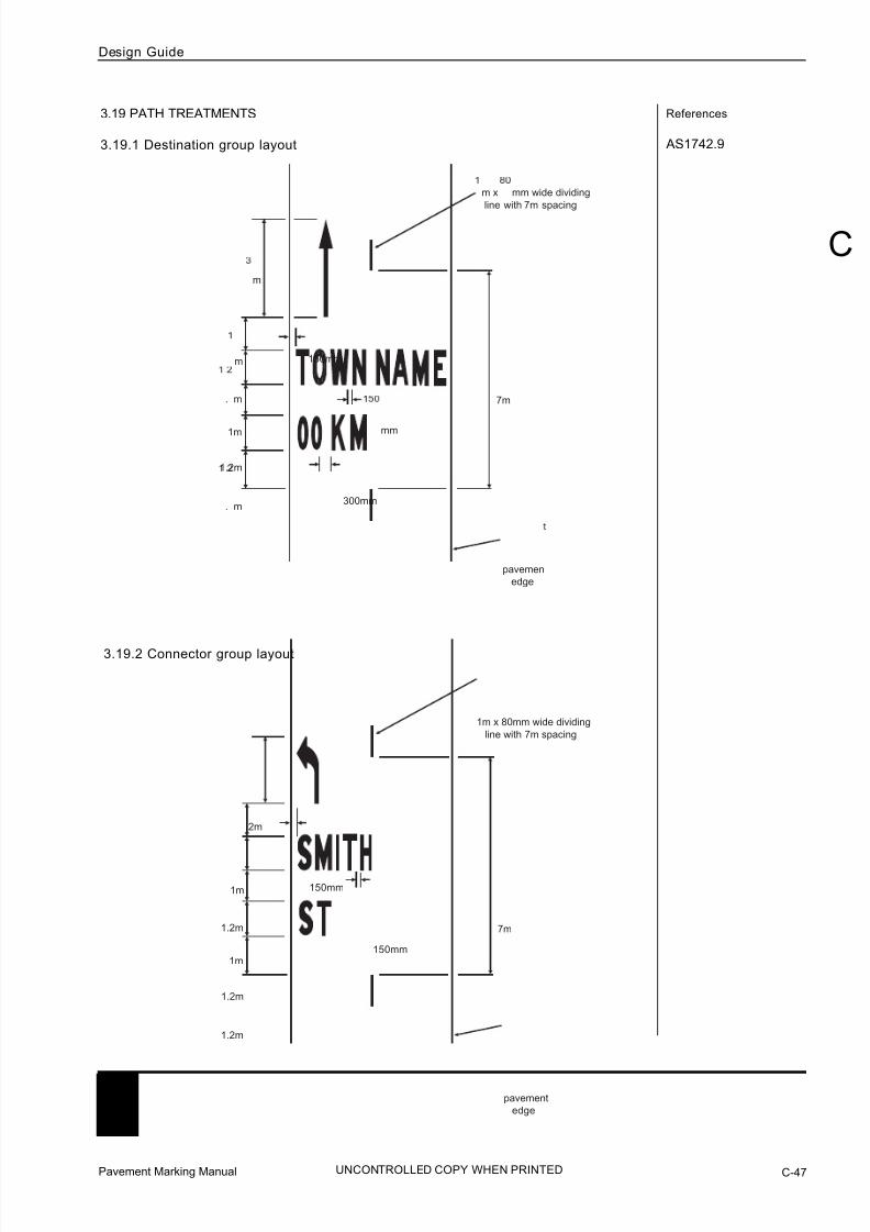
7/25/2019 Road Marking Guidelines
http://slidepdf.com/reader/full/road-marking-guidelines 117/159
Pavement Marking Manual C-47
Design Guide
C
UNCONTROLLED COPY WHEN PRINTED
References
AS1742.9
7m
. m
1.2m
1m
. m
m
m
150mm
300mm
m x mm wide dividing
line with 7m spacing
pavemen
edge
mm
3.19 PATH TREATMENTS
3.19.1 Destination group layout
7m
1.2m
1.2m
1m
1.2m
1m
2m
150mm
150mm
pavement
edge
1m x 80mm wide dividing
line with 7m spacing
3.19.2 Connector group layout

7/25/2019 Road Marking Guidelines
http://slidepdf.com/reader/full/road-marking-guidelines 118/159
References3.19.3 Shared use paths, T in tersection layout
5m
10m
m
10m
50m
15m min
destination group
ee Part C 3.19.1or typical layout
connector group
see Part C 3.19.2
for typical layout
0m
15m min
12m x 80mm wide
single continuous line
1m x 7m gap x 80mm wide
dividing line
ymbol groups should
be spaced at not more
than 200m intervals
connector path eg.
SMITH STREET
destination group
see Part C 3.19.1for typical layout
onnector group
ee Part C 3.19.2
for typical layout
Pavement Marking ManualC-48
Design Guide
UNCONTROLLED COPY WHEN PRINTED

7/25/2019 Road Marking Guidelines
http://slidepdf.com/reader/full/road-marking-guidelines 119/159
Pavement Marking Manual C-49
Design Guide
C
UNCONTROLLED COPY WHEN PRINTED
References3.19.4 Shared use paths, intersection layout
m
10m
15m min
25m
connector path eg.
MITH TREE
m
1 m
connector path eg.
NE AVEN
15m min
m
1 m min
symbol groups shoul
be spaced at not more
than 2 m intervals
estination group
see Part .1 .1
for typical layout
onnector group
see Part .1 .
or typical layout
destination groupsee Part C 3.19.1
or typical layout
connector group
see Part .19.2
for typical layout
connector group
see Part C 3.19.2
for typical layout
connector group
see Part C .19.
or typical layout
1 m x mm wi e
ingle continuous line
1m x 7m gap x 80mm wide
dividing line

7/25/2019 Road Marking Guidelines
http://slidepdf.com/reader/full/road-marking-guidelines 120/159
References3.19.5 Shared use paths, T intersection offset layout
m
10m
0m
m
m
15m min
m
m
1 m min
symbol groups shoul
be spaced at not more
then m intervals
connector path eg.
SMITH STREE
onnector path eg.
JONES AVENUE
m
destination group
see Part C 3.19.1
for typical layout
connector group
see Part C 3.19.2
for typical layout
destination group
see Part C 3.19.1
for typical layou
onnector group
see Part C 3.19.2
for typical layout
connector group
see Part C 3.19.2
for typical layout
connector group
see Part C 3.19.2
for typical layout
12m x 80mm wide
single continuous line
1m x 7m gap x 80mm wide
ivi ing line
12m x 80mm wide
ingle continuous line
Pavement Marking ManualC-50
Design Guide
UNCONTROLLED COPY WHEN PRINTED

7/25/2019 Road Marking Guidelines
http://slidepdf.com/reader/full/road-marking-guidelines 121/159
Pavement Marking Manual C-51
Design Guide
C
UNCONTROLLED COPY WHEN PRINTED
References
AS1742.10
3.20 PEDESTRIAN FACILITIES
There are a number of distinctive facilities to assist the safe passage of pedestrians walking
adjacent to and across roads. The distinctive features including the legal effect for some of
these facilities is partly created by the pavement markings.
These facilities are:
Pedestrian refuge
Emu crossing
Koala crossing
Wombat crossing
Pedestrian actuated crossing
3.20.1 Pedestrian refuge
Refuges shall be outlined and the outline shall continue past the pedestrian opening.
Where pedestrian openings are provided through medians, outlines shall also continue
past the opening or a line placed across the opening as shown in Part B 2.16.5.
Where the pedestrian refuge divides opposing traffic movements unidirectional yellow
RRPMs shall be provided at 6.0m spacings. White RRPMs shall be provided at the samespacing where the refuge separates traffic travelling in the same direction.
Special purpose broken line should be used for lane line for short isolated pedestrian refuges
on multi-lane roads.
Pedestrian refuges are either short lengths of raised medians used on roads for the sole
purpose of providing a staging area for pedestrians crossing the road or are long lengths of
median through which ‘cut outs’ or ‘walkthroughs’ may be provided.
minimum treatment for
two-lane two-way
W
30m min
Td = V W 3.6
Td = diverge length (m)
V = design speed or speed limit (km\h)
W = lateral movement (m)
S = rate of lateral movement (m/s)
(0.6 m/s for multi-lane two-way
undivided and preferred for
two-lane two-way)
3m
multi-lane two-way undivided and preferred
treatment for two-lane two-way
W
30m min
Td = V W 3.6S
enhanced
enhanced broken line
(9m line 3m gap 200wide)
standardlane line
special purpose broken line

7/25/2019 Road Marking Guidelines
http://slidepdf.com/reader/full/road-marking-guidelines 122/159
References
The Code Section 8 AS1742.10
3.20.2 Emu crossing
two-lane two-way road
two-lane two-way road (with kerb extensions)
6m 2.4m - 6m
6m
post and flag
single broken
dividing line
kerb
kerb
standard stop line
post and flag
postpost
post post
6m 2.4m - 6m
6m
kerb
kerb
standard stop line
kerb
extension
post and flag
single broken
dividing line
post and flag
postpost
postpost
kerb extension
kerb
extension
Pavement Marking ManualC-52
Design Guide
UNCONTROLLED COPY WHEN PRINTED

7/25/2019 Road Marking Guidelines
http://slidepdf.com/reader/full/road-marking-guidelines 123/159
Pavement Marking Manual C-53
Design Guide
C
UNCONTROLLED COPY WHEN PRINTED
References
AS1742.10
6m 2.4m - 6m
6m
kerb
kerb
standard stop line
twin alternate yellow
flashing signals
kerb
extension
single broken
dividing line
kerb extension
kerb
extension
3.20.3 Koala crossing
two-lane two-way road
two-lane two-way road (with kerb extensions)
6m 2.4m - 6m
6mtwin alternate yellow
flashing signals
kerb
kerb
standard stop linesingle broken
dividing line

7/25/2019 Road Marking Guidelines
http://slidepdf.com/reader/full/road-marking-guidelines 124/159
References
The Code Section 8 AS1742.10
3.20.4 Wombat and Zebra crossings
Wombat crossing
two-lane two-way road
divided carriageway
Zebra crossing
off-street
10m minimum**
6.6m minimum
6m minimum
raised median raised median
10m minimum**
1.2m min1.2m min
** A single barrier line should be provided on
each approach if the road has a dividing line
* Equal, 0.3m minimum
4m minimum
6.6m minimum
6m minimum
1.2m min1.2m min
* Equal, 0.3m minimum
Top of rampTop of ramp **
Top of rampTop of ramp **
Pavement Marking ManualC-54
Design Guide
UNCONTROLLED COPY WHEN PRINTED

7/25/2019 Road Marking Guidelines
http://slidepdf.com/reader/full/road-marking-guidelines 125/159
Pavement Marking Manual C-55
Design Guide
C
UNCONTROLLED COPY WHEN PRINTED
References
AS1742.10
3.20.5 Pedestrian actuated crossing
Undivided roads
two-lane two-way
four-lane two-way
6m
6m
single post with
pedestrian push button
kerb
kerb
standard stop line
20m single continuous
barrier line (optional)
refer to Part C 3.1
5m preferred
(2.4m min)
kerb
kerb
standard stop line
6m
6m
single post with
pedestrian push button
20m single enhanced continuous
barrier line (optional) refer to Part C 3.1
5m preferred
(2.4m min)

7/25/2019 Road Marking Guidelines
http://slidepdf.com/reader/full/road-marking-guidelines 126/159
References
ARR 23
The Code Section 4
3.21 SCHOOL ZONES
A zigzag marking is used to increase driver awareness of a school zone. It is placed in
advance of a School Zone sign, subject to site conditions.
Zigzag pavement markings shall be used at all School Zones.
Typically the trailing end of the zigzag marking is placed at the school zone sign with the
marking commencing 30m in advance of the sign.
‘SCHOOL’ pavement messages may be used where visibility to the R3-SA58 School Zone
sign is limited by the horizontal or vertical alignment of the road. This message may
supplement the WG-SA106 School Zone warning sign(s) in which case the message shall
be adjacent the sign see Part C 3.21.3.
Other markings, such as speed limits, coloured patches or symbols shall not be used.
The zigzag markings must be as shown in Part B 2.9, unless otherwise indicated in the
following examples.
3.21.1 Zigzag marking position
(a) Parking prohibited at all times.
(b) Adjacent indented parking lane and full time bicycle lane.
(c) Adjacent wide kerbside lane.
edgeline or edge of seal
dividing line or centre of road
zigzag positioned centrally in lane
R3-SA58
kerb extensions may be presentto provide protected parking lane
bicycle lane (full time)
marked parking lane
zigzag positionedcentrally in lane
median or dividing line
R3-SA58
R3-SA58
a part-time bicycle lane may be installed
zigzag positionedcentrally in lane
median or dividing line
lane widtha (see below)
indicates direction of travel
R3-SA58
R3-SA58
Pavement Marking ManualC-56
Design Guide
UNCONTROLLED COPY WHEN PRINTED

7/25/2019 Road Marking Guidelines
http://slidepdf.com/reader/full/road-marking-guidelines 127/159
Pavement Marking Manual C-57
Design Guide
C
UNCONTROLLED COPY WHEN PRINTED
References(d) Part time parking restriction.
3.21.2 Basic school zone
3.21.3 Curved alignment
lane width
a (see below)
dividing line or centre of road
Width of lane Value of a
less than or equal to 4.0m 0.2m
between 4.0m to 6.0m 0.6m
greater than 6.0m 1.2m
R3-SA58
R3-SA58
R4-SA59R3-SA58
R4-SA59R3-SA58
R3-SA58R4-SA59
R3-SA58R4-SA59
R 4 - S
A 5 9
R 3 - S
A 5
8
R 3 - S A 5 8
R 4 - S A 5 9
R 3 - S A 5 8
R 4 - S A 5 9
1
2
R 4 - S
A 5 9
R 3 - S
A 5 8
WG-SA106 S C H O O L
indicates direction of travel
Notes :
1. ‘SCHOOL’ pavement message may be used
adjacent to a WG-SA106 School Zone warning
sign where sight distance to the R3-SA58School Zone sign may be restricted.
2. Zigzag shall follow the curve of the road.

7/25/2019 Road Marking Guidelines
http://slidepdf.com/reader/full/road-marking-guidelines 128/159
References3.21.4 At intersections and Emu crossings
3.21.5 Undivided multi-lane road
Notes :
1. Zigzag marking should be 30m long but may be reduced to a minimum of 21m.
2. Zigzag markings must not extend into an intersection. It must be clear of the
prolongation of the kerb or edge of road by at least 1.0m.
3. Prolongation of kerb or edge of road.
4. Zigzag marking may retain its length by extending past the School Zone sign i.e.where sign installation may be restricted due to driveways.
3.0m min
1
2
1
1.0m min
23
30m
3 1
21m min
for Emu crossingsrefer to Part C 2.20.2
R3-SA58
R3-SA58
1.0m min
4
30m
1.0m min
2
3
R3-SA58
R3-SA581
R4-SA59R3-SA58
R3-SA58R4-SA59
R3-SA58
R3-SA58
indicates direction of travel
Pavement Marking ManualC-58
Design Guide
UNCONTROLLED COPY WHEN PRINTED

7/25/2019 Road Marking Guidelines
http://slidepdf.com/reader/full/road-marking-guidelines 129/159
Pavement Marking Manual C-59
Design Guide
C
UNCONTROLLED COPY WHEN PRINTED
References
3.22 BUS FACILITIES
Bus facilities on roads include part time Bus Lanes, full time Bus Lanes and Bus Only areas.
All three are pavement marked differently.
General requirements:
For Bus Lane widths on an urban arterial road agreement shall be sought from
Operational Services, DPTI.
At the start of a Bus Lane where road users are required to diverge to avoid entering the
lane, a continuity line transition shall be provided.
Full time Bus Lanes shall have an continuous lane line.
Part time Bus Lanes shall have a special purpose broken lane line.
BUS LANE AHEAD pavement messages placed in advance of the continuity line transition
are preferred for both full and part time Bus Lanes.
BUS LANE pavement messages must be placed at the start of both full and part time Bus
Lanes after intersections and at intervals not exceeding 200 metres.
BL pavement messages shall not be used.
Continuity line transitions lines shall be
- Not less than 35 metres where traffic is not required to merge with another lane of traffic
to avoid entering the Bus lane.
- Full merging transition length where traffic is required to merge with another lane.
Pavement messages need not be in lateral alignment with Bus lane signs.
Red pavement colouring in a lane or part of a lane shall only be used with a Bus Only
pavement message. Red shall not be used for any other purpose.
3.21.6 Divided mult i-lane road
indicates direction of travel
R3-SA58
R3-SA58
R4-SA59
R4-SA59
R4-SA59
R4-SA59 R3-SA58
R3-SA58
>3m
<3m

7/25/2019 Road Marking Guidelines
http://slidepdf.com/reader/full/road-marking-guidelines 130/159
References
AS1742.12
3.22.1 Placing of l ane messages
bus lane
2.5m 1.2m - 2.5m 2.5m 2.5m1.2m - 2.5m
2.5m 1.2m - 2.5m 2.5m
special purpose broken line
bus lane
2.5m 1.2m - 2.5m 2.5m
continuous lane line
2.5m 1.2m - 2.5m 2.5m
continuous lane line
Indicates direction of travel
Bus Lane Ahead
Part Time Bus Lane
Full Time Bus Lane
Bus Only
Pavement Marking ManualC-60
Design Guide
UNCONTROLLED COPY WHEN PRINTED

7/25/2019 Road Marking Guidelines
http://slidepdf.com/reader/full/road-marking-guidelines 131/159
Pavement Marking Manual C-61
Design Guide
C
UNCONTROLLED COPY WHEN PRINTED
References
6.2m - 7.5m
35m
kerb
35m - 100m
continuity
line
3.22.1 Placing of lane messages (cont )

7/25/2019 Road Marking Guidelines
http://slidepdf.com/reader/full/road-marking-guidelines 132/159
References
ARR 154, 158, 187
AS1742.12 Section 6
3.22.2 Full -time / Part-time bus lanes
Full-time bus lane
10m
to50m
200m max
100m
7.5m
35m
30m to100m
12.5m
Part-time bus lane
10m
to50m
200m max
7.5m
35m
30m to100m
12.5m
special purpose broken linecontinuous lane line
Pavement Marking ManualC-62
Design Guide
UNCONTROLLED COPY WHEN PRINTED

7/25/2019 Road Marking Guidelines
http://slidepdf.com/reader/full/road-marking-guidelines 133/159
Pavement Marking Manual C-63
C
Design Guide
C
UNCONTROLLED COPY WHEN PRINTED
References
AS1742.12
GRD Part 3
3.22.3 Parking bays in Bus Lanes
Parking bays should not normally be marked in part-time bus lanes. However, when they
are required, they should be marked with “T” and “L” markings.
3.22.4 Bus Only

7/25/2019 Road Marking Guidelines
http://slidepdf.com/reader/full/road-marking-guidelines 134/159
Pavement Marking ManualC-64
Design Guide
UNCONTROLLED COPY WHEN PRINTED
References3.22.4 Bus Only (cont )
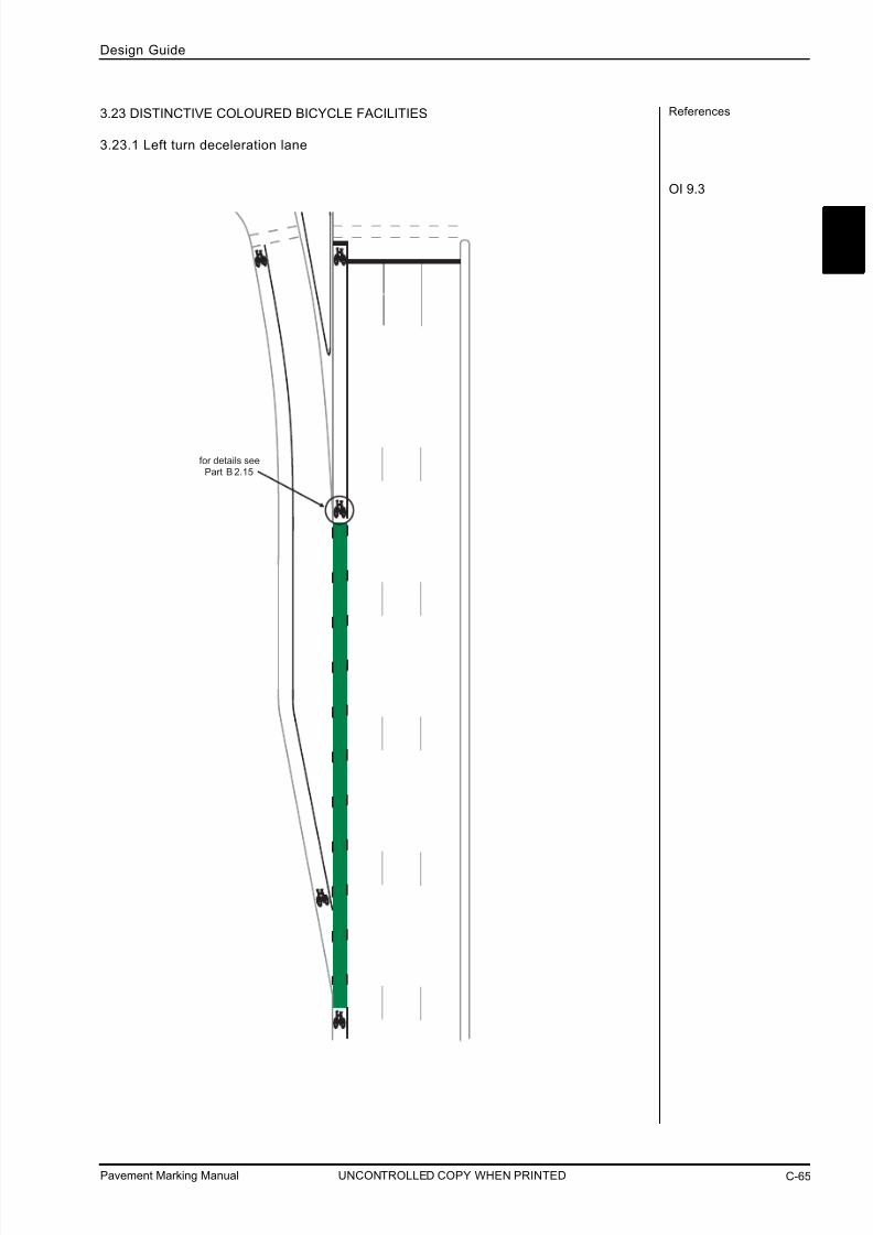
7/25/2019 Road Marking Guidelines
http://slidepdf.com/reader/full/road-marking-guidelines 135/159

7/25/2019 Road Marking Guidelines
http://slidepdf.com/reader/full/road-marking-guidelines 136/159
Pavement Marking ManualC-66
Design Guide
UNCONTROLLED COPY WHEN PRINTED
References
OI 9.3
3.23.2 Left turn acceleration lane

7/25/2019 Road Marking Guidelines
http://slidepdf.com/reader/full/road-marking-guidelines 137/159
Pavement Marking Manual C-67
C
Design Guide
C
UNCONTROLLED COPY WHEN PRINTED
References
OI 9.3
OI 9.3
3.23.3 High angle left turn lane
3.23.4 Minor side road junction
for the extent of continuityline see Part C 3.7.3

7/25/2019 Road Marking Guidelines
http://slidepdf.com/reader/full/road-marking-guidelines 138/159
Pavement Marking ManualC-68
Design Guide
UNCONTROLLED COPY WHEN PRINTED
References3.23.5 Bicyc le storage area (with a bicycle lane)
NOTES: 1. For bicycle logo details see AS1742.3 - 2000.
2. Green coloured pavement surface shall be Emerald Green G13.
4.0m minimum
k e r b
x*x*x*
x* symbols to be
evenly spaced
place symbol at the
start of the continuity line
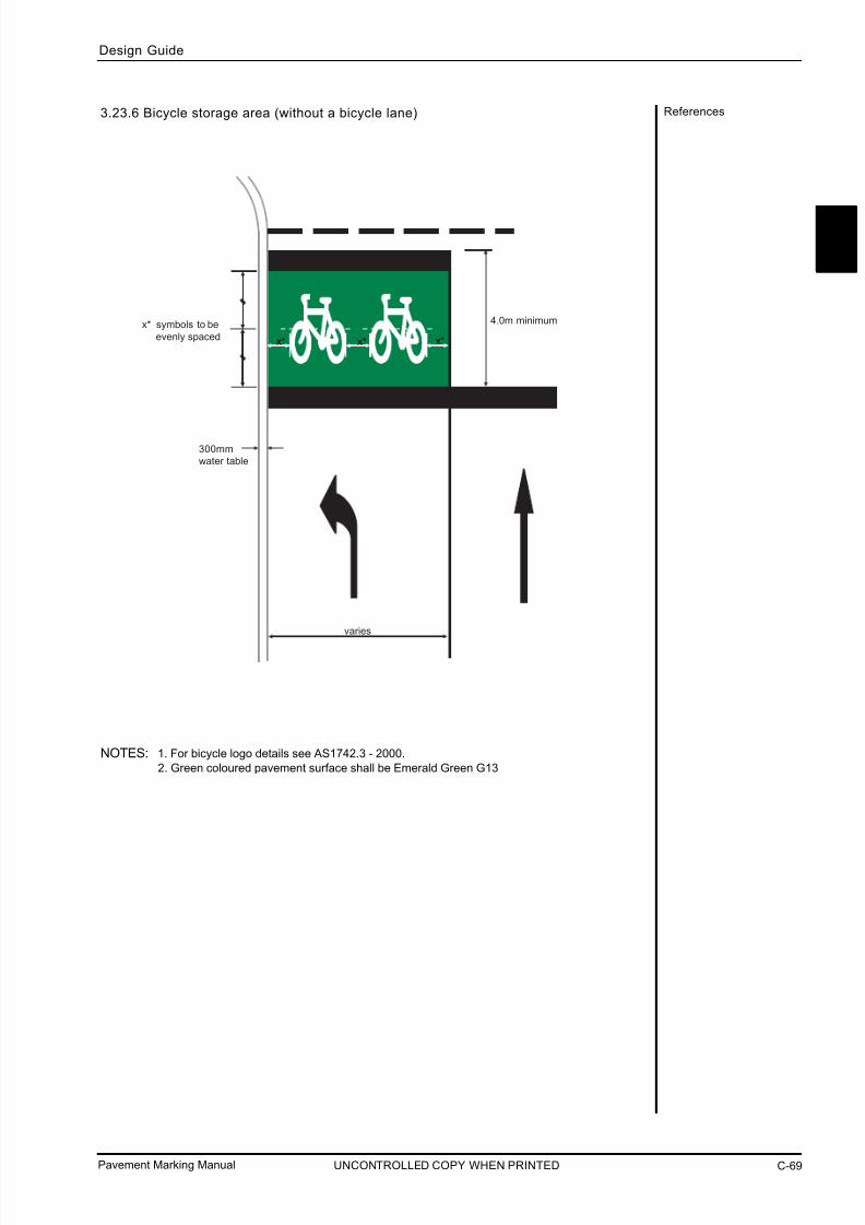
7/25/2019 Road Marking Guidelines
http://slidepdf.com/reader/full/road-marking-guidelines 139/159
Pavement Marking Manual C-69
C
Design Guide
C
UNCONTROLLED COPY WHEN PRINTED
References3.23.6 Bicycle storage area (without a bicycle lane)
NOTES: 1. For bicycle logo details see AS1742.3 - 2000.
2. Green coloured pavement surface shall be Emerald Green G13
4.0m minimum
x*x*x*
x* symbols to be
evenly spaced
varies
300mm
water table

7/25/2019 Road Marking Guidelines
http://slidepdf.com/reader/full/road-marking-guidelines 140/159
3.24 OTHER BICYCLE FACILITIES
3.24.1 Indented hook turn
holding rail
3m
3m
1.2m
6m
5.8m
1.5m
1.8m
start continuity line
References
Pavement Marking ManualC-70
Design Guide
UNCONTROLLED COPY WHEN PRINTED

7/25/2019 Road Marking Guidelines
http://slidepdf.com/reader/full/road-marking-guidelines 141/159
Pavement Marking Manual C-71
C
Design Guide
C
UNCONTROLLED COPY WHEN PRINTED
References3.24.2 Detector loop
160mm
kerb or edge line
250mm
500mm
300mm
6 diamond markings
(100mm x 100mm)
at 300mm centers
lane line
stop line
250mm

7/25/2019 Road Marking Guidelines
http://slidepdf.com/reader/full/road-marking-guidelines 142/159
Pavement Marking ManualC-72
Design Guide
UNCONTROLLED COPY WHEN PRINTED
References
GRD Part 3GRD Part 4A
ARR 132, 134
AS1742.2 Section 5
AS1742.7 Section 3
OI 2.15
4.0 RURAL TREATMENTS
This section details the pavement marking differences between the general or urban
treatments and those in rural areas. In cases other than those listed below, treatments should
be the same for both built up urban and rural situations.
4.1 DIVIDED RURAL ROADS
Although most of the design details for treatments between intersections in this section relate
to undivided roads, the same principles, with the exception of dividing lines, should be applied
for divided roads.
4.2 MULTI-LANE UNDIVIDED RURAL ROADS
Multi-lane undivided roads shall not be used in high speed rural environments with the
exception of specific treatments such as overtaking lanes, channelised right turn treatment
(CHR) and channelised left turn treatment (CHL).
4.3 DIVIDING LINES ON RURAL ROADS
Dividing lines shall be installed in accordance with AS1742.2 other than at isolatedintersections treatments. The use of single continuous barrier lines as dividing lines are not
recommended in high speed rural environments. Although such lines prohibit certain crossing
movements, including u-turns, they do not prohibit entering or leaving the road (see Barrier
Lines on Rural Roads).
Any assessment for the need for dividing l ines needs to consider the following:
All rural ‘arterial’ roads shall be provided with dividing lines and should be augmented with
RRPMs.
All rural ‘collector’ roads should be provided with dividing lines.
Local rural roads may be provided with dividing lines. Installing dividing lines on narrow
roads may have implications for parking.
Where provided between major rural intersections dividing lines should be broken, and
shall be standard width for 2 lane roads and enhanced for multi lane roads.
Where provided on minor or local rural roads at intersections, short sections of single
continuous barrier line may be provided.
Dividing lines on rural arterial roads through minor road intersections are generally broken
(see Part B 2.4 Rural Intersections).
4.4 BARRIER LINES ON RURAL ROADS
A single continuous barrier line should be used through rural townships as an alternative to
double two-way barrier lines. This allows the line to be crossed by traffic entering or leaving
the road.
Barrier lines on high speed rural roads shall only consist of double lines, either ‘Double One
Way Barriers’ or ‘Double Two Way Barriers’ to create ‘No Overtaking Zones’ and shall be
restricted to locations with either horizontal or vertical sight restrictions or both and only be
determined in accordance with AS1742.2.
Double barrier lines, one way or two way, are not generally used in SA to prohibit overtaking
at isolated locations unless there are sight restrictions which meet the requirements for suchlines.
The only exceptions to the above requirement include:
Railway level crossings in accordance with Australian Standards Manual of Uniform Traffic
Control Devices (AS1742.7). Overtaking lanes in accordance with this document and Operational Instruction 2.15
Ferry approaches in accordance with Australian Standards Manual of Uniform Traffic
Control Devices.

7/25/2019 Road Marking Guidelines
http://slidepdf.com/reader/full/road-marking-guidelines 143/159
Pavement Marking Manual C-73
C
Design Guide
C
UNCONTROLLED COPY WHEN PRINTED
References
AS1742.2
4.5 WIDE DIVIDING LINE TREATMENTS
For wide dividing line treatments the following requirements for the establishment of no-
overtaking zones apply. For all other locations, refer to AS1742.2.
For 110km/h design speed
Minimum overtaking sight distance 590m
Barrier line distance 280m
Maximum length with no Barrier Lines 55m*
Minimum length of Barrier Lines 165m
Minimum distance between Barrier Lines 310m
For 120km/h design speed
Minimum overtaking sight distance 690m
Barrier line distance 330m
Maximum length with no Barrier Lines 60m*
Minimum length of Barrier Lines 180m
Minimum distance between Barrier Lines 350m
*where a short length of road has substandard overtaking sight distance, barrier lines should
not be marked e.g. short sag (floodway) on an otherwise level road.
4.6 LANE LINES ON RURAL ROADS
Lane lines i.e. lines dividing lanes of the same direction traffic, must be provided on roadswhere traffic is expected to travel in more than one line of traffic.
Lanes should not be marked on a rural road where it would result in lane widths of less than
3.2 metres. Restricted access routes may require greater lane widths.
Lane lines are normally standard broken. However, unbroken lane lines may be used between
exclusive through and exclusive turn lanes on approaches to intersections.
Lane lines on rural roads should be continued through minor road intersections.
All multi lane divided rural roads shall be provided with enhanced edge l ines and outlines.
Multi lane divided rural road
enhanced edge line
sealed shoulder or emergency stopping lane
dividing strip (kerbed)(unkerbed)
enhanced edge line
175mm
min
enhanced outline
sealed shoulder or emergency stopping lane

7/25/2019 Road Marking Guidelines
http://slidepdf.com/reader/full/road-marking-guidelines 144/159
Pavement Marking ManualC-74
Design Guide
UNCONTROLLED COPY WHEN PRINTED
References
AS1742.2 Section 4
AS1742.2 Section 5
GRD Part 3
AS1742.2 Section 4
4.7.1 Narrow rural two-lane two-way road (sealed width >5.5m, <6.8m)
> 5.5m
u n s e a l e
d
s h o u l d e r
u n s e al e d s h o ul d er
edge of seal(no edge line unless
AS1742.2 clause 4.2.2.1 (b) or clause 5.3.2.4 applies)
4.7 EDGE LINES ON RURAL ROADS
Edge lines shall be provided on all rural roads to ensure the lane width does not exceed 3.5
metres.
Edge lines provide a clear definition of the lane both day and night and discourage traffic from
travelling on shoulders.
Practices regarding lane and sealed shoulder widths including the issues relating to pavement
depth, should be considered before providing an edge line.
Part C 4.7.1 and 4.7.2 show best practice in regard to installing edge lines.
Part C 4.7.3 and 4.7.4 indicates a required treatment.

7/25/2019 Road Marking Guidelines
http://slidepdf.com/reader/full/road-marking-guidelines 145/159
Pavement Marking Manual C-75
Design Guide
UNCONTROLLED COPY WHEN PRINTED
C
References4.7.2 Standard ru ral two-lane two-way road
(sealed width >6.8m)
> 6.4m
> 6.8m
(seal width)
standard edge line
u n
s e a l e d
s h o
u l d e r
u n s e al e d s h o ul d er
edge of seal
minimum width 200mm
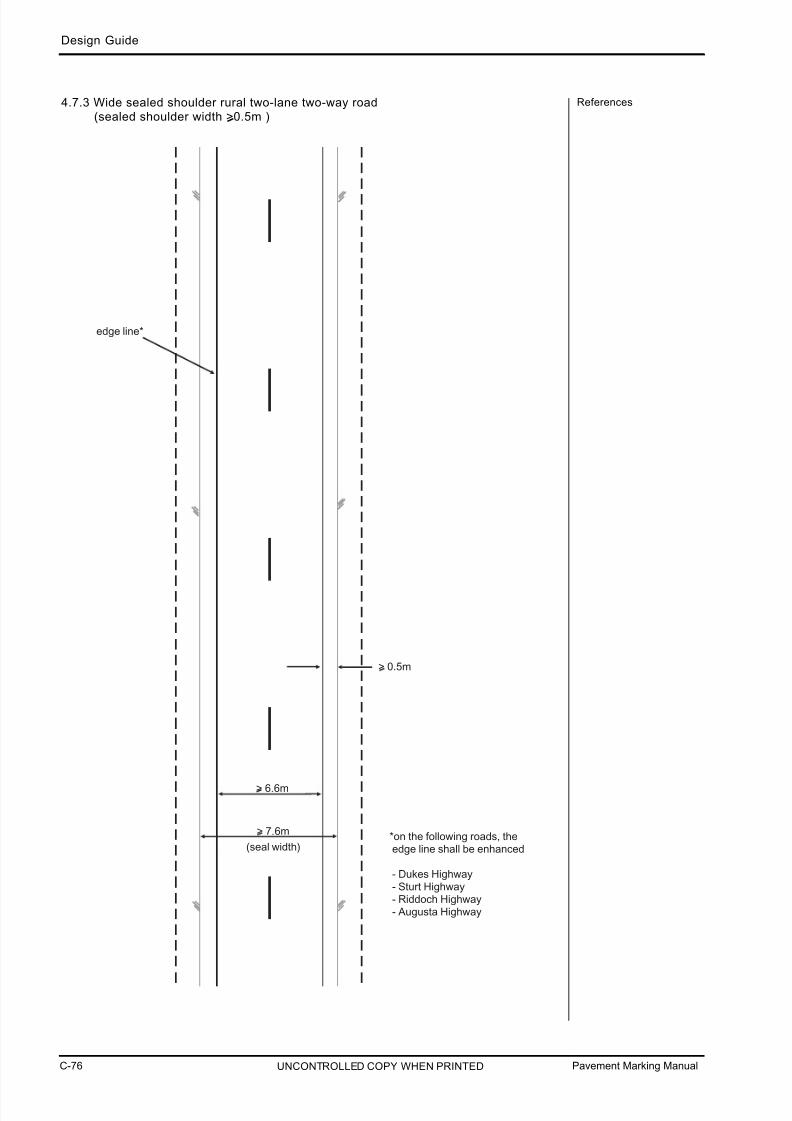
7/25/2019 Road Marking Guidelines
http://slidepdf.com/reader/full/road-marking-guidelines 146/159
Pavement Marking ManualC-76
Design Guide
UNCONTROLLED COPY WHEN PRINTED
References4.7.3 Wide sealed shoulder rural two-lane two-way road(sealed shoulder width >0.5m )
> 6.6m
> 7.6m
(seal width)
edge line*
> 0.5m
*on the following roads, the edge line shall be enhanced
- Dukes Highway - Sturt Highway - Riddoch Highway - Augusta Highway
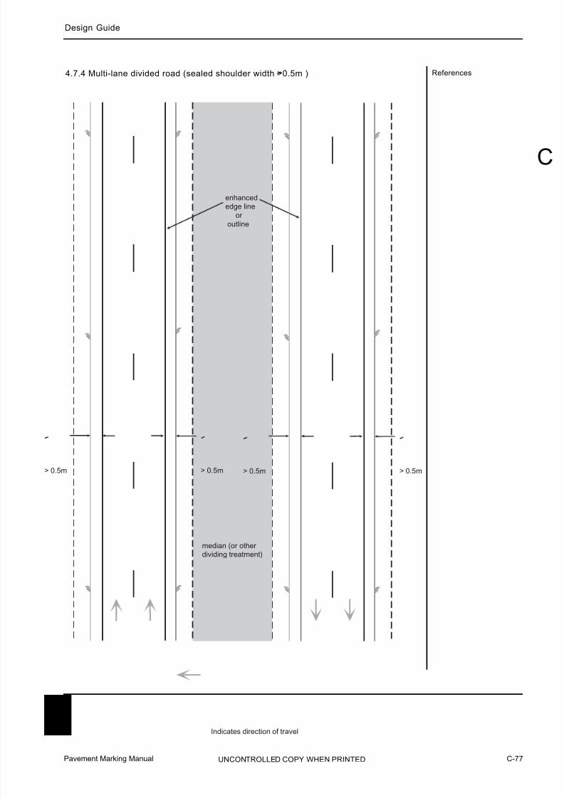
7/25/2019 Road Marking Guidelines
http://slidepdf.com/reader/full/road-marking-guidelines 147/159
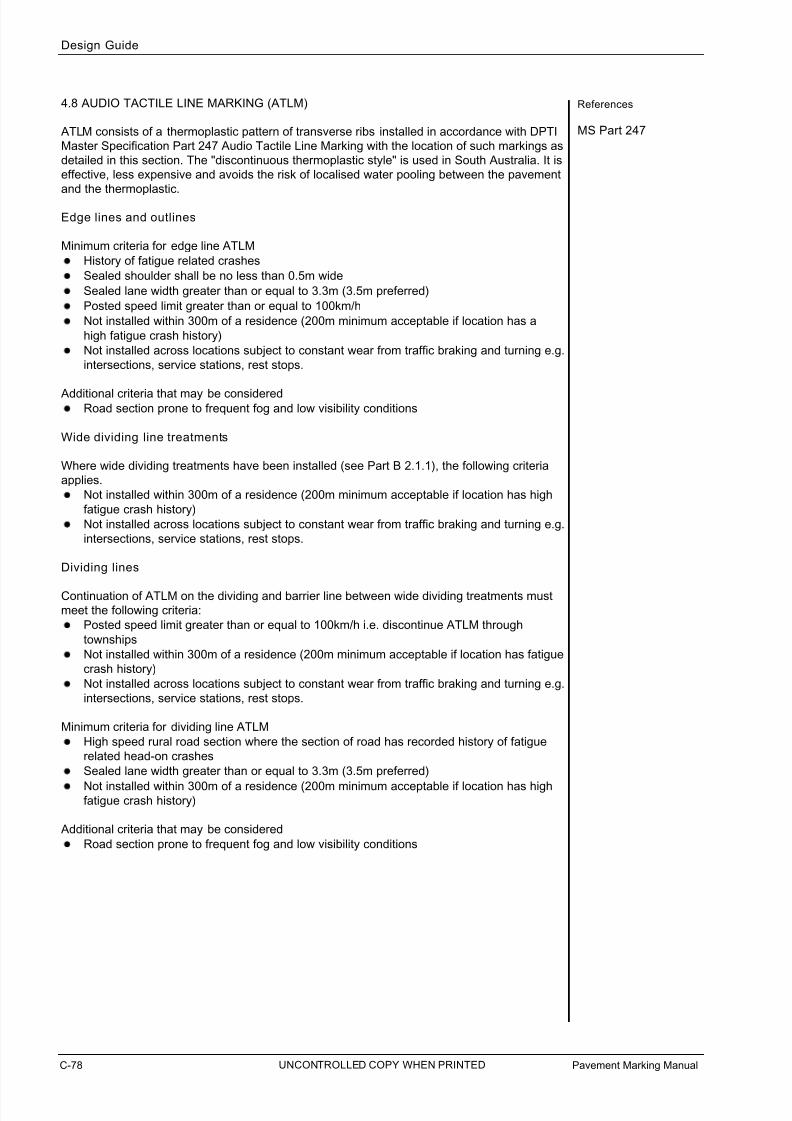
7/25/2019 Road Marking Guidelines
http://slidepdf.com/reader/full/road-marking-guidelines 148/159
Pavement Marking ManualC-78
Design Guide
UNCONTROLLED COPY WHEN PRINTED
References
MS Part 247
4.8 AUDIO TACTILE LINE MARKING (ATLM)
ATLM consists of a thermoplastic pattern of transverse ribs installed in accordance with DPTI
Master Specification Part 247 Audio Tactile Line Marking with the location of such markings as
detailed in this section. The "discontinuous thermoplastic style" is used in South Australia. It is
effective, less expensive and avoids the risk of localised water pooling between the pavement
and the thermoplastic.
Edge lines and outlines
Minimum criteria for edge line ATLM
History of fatigue related crashes
Sealed shoulder shall be no less than 0.5m wide
Sealed lane width greater than or equal to 3.3m (3.5m preferred)
Posted speed limit greater than or equal to 100km/h
Not installed within 300m of a residence (200m minimum acceptable if location has a
high fatigue crash history)
Not installed across locations subject to constant wear from traffic braking and turning e.g.
intersections, service stations, rest stops.
Additional criteria that may be considered Road section prone to frequent fog and low visibility conditions
Wide dividing line treatments
Where wide dividing treatments have been installed (see Part B 2.1.1), the following criteria
applies.
Not installed within 300m of a residence (200m minimum acceptable if location has high
fatigue crash history)
Not installed across locations subject to constant wear from traffic braking and turning e.g.
intersections, service stations, rest stops.
Dividing lines
Continuation of ATLM on the dividing and barrier line between wide dividing treatments must
meet the following criteria:
Posted speed limit greater than or equal to 100km/h i.e. discontinue ATLM through
townships
Not installed within 300m of a residence (200m minimum acceptable if location has fatigue
crash history)
Not installed across locations subject to constant wear from traffic braking and turning e.g.
intersections, service stations, rest stops.
Minimum criteria for dividing line ATLM
High speed rural road section where the section of road has recorded history of fatigue
related head-on crashes
Sealed lane width greater than or equal to 3.3m (3.5m preferred)
Not installed within 300m of a residence (200m minimum acceptable if location has highfatigue crash history)
Additional criteria that may be considered
Road section prone to frequent fog and low visibility conditions

7/25/2019 Road Marking Guidelines
http://slidepdf.com/reader/full/road-marking-guidelines 149/159
Pavement Marking Manual C-79
Design Guide
UNCONTROLLED COPY WHEN PRINTED
C
References
AS1742.2 Section 2
GRD Part 3OI 2.15
4.9 OVERTAKING LANE TREATMENTS
More details in Operational Instruction 2.15 Overtaking Lanes.
C
e d g e l i n e
e d g e l i n e
V C
C
D = VW 3
W
km/h m
75 - 90 60
>90 96
85
D = Diverge
V = Design Speed (km/h)
W = Lateral movement (m)
4.9.1 Overtaking lane - diverge

7/25/2019 Road Marking Guidelines
http://slidepdf.com/reader/full/road-marking-guidelines 150/159
Pavement Marking ManualC-80
Design Guide
UNCONTROLLED COPY WHEN PRINTED
References4.9.2 Overtaking lane - merge
A
V A
km/h m
<75 100
75-90 150
>90 250
85
.
.
A2
W4-9C
W8-15C
G9-73B
W

7/25/2019 Road Marking Guidelines
http://slidepdf.com/reader/full/road-marking-guidelines 151/159
Pavement Marking Manual C-81
C
Design Guide
UNCONTROLLED COPY WHEN PRINTED
References
ARR 167, 168, 169
AS1742.2 Section 4
GRD Part 3
4.10 SLOW VEHICLE TURNOUTS
Slow vehicle turnouts are short sections of sealed shoulder or added lane to provide drivers of
slow-moving vehicles an area to be overtaken or passed by another vehicle where constraints
do not allow provision of a full overtaking or climbing lane. Located on low speed, winding or
hilly two-lane two-way roads, which have limited passing opportunities, they consist of a
widened unobstructed sealed shoulder and are most effective if used in a series along a
section of road.
Turnouts should be located where drivers of slow moving vehicles believe their use will notresult in undue delay. Turnouts should not be interspersed with overtaking or climbing lanes.
Drivers should have a clear view of the entire turnout to determine whether it is available for
use and to anticipate the movement of any other vehicles which may be exiting. Experience
suggests that turnouts which cannot be seen for some distance by approaching drivers are
less likely to be used.
A total length of 80-100m (including tapers) is considered suitable for most environments.
Total length should not exceed 160m. The lengths below are provided as a guide.
Mean Approach *Rec. overallSpeed (km/h) Length (m)
<50 60
50 - 59 8060 - 69 100
70 - 79 135
>80 160
* These lengths are based on the assumption that slow moving vehicles enter the turnout
8km/h slower than the mean speed of the through traffic. They are sufficient to allow a vehicle
to enter the turnout at the assumed speed, coast to the midpoint and then, if necessary, stopin the remaining length using a deceleration rate of 3 m/s .
No Parking or No Stopping?
If the driver of the slow moving vehicle were to stop in the slow vehicle turnout to allow
multiple vehicles to pass and No Stopping signs and/or yellow edge lines were installed, the
driver could be committing an offense under ARR 167 and ARR 169 respectively. Therefore,No Stopping signs and yellow edge lines shall not be used.
No Parking signs shall be installed to allow drivers to stop for short periods (up to 2 minutes -
see ARR 168).
2

7/25/2019 Road Marking Guidelines
http://slidepdf.com/reader/full/road-marking-guidelines 152/159
Pavement Marking ManualC-82
Design Guide
UNCONTROLLED COPY WHEN PRINTED
References
GRD Part 6
edge linesedge of seal
edge of seal
edge lines
e d g e
o f u n s e a l e d s h o u l d e r
g e n e r a l l y 8 0 m -
1 0 0 m
1 5 m -
3 0 m
1 5 m -
3 0 m
3.7m
min1.0m
Slow vehicle turnout

7/25/2019 Road Marking Guidelines
http://slidepdf.com/reader/full/road-marking-guidelines 153/159
Pavement Marking Manual C-83
C
Design Guide
UNCONTROLLED COPY WHEN PRINTED
References
ARR 150 (1B), (3)
OI 20.3
4.11 REST AREAS
Rest areas may be lay bys, truck (only) parking bays, information bays, and points of interest
sites. These may be sealed or unsealed.
4.11.1 Roads wi th edge lines
acceleration
lane
sealed shoulder only
(typically >3.0m)
edge of
existing seal
continuity line
edge line
sealed
shoulder only
length of continuity line for both accelerationand deceleration (if provided) see Part C 3.7 *
*
*

7/25/2019 Road Marking Guidelines
http://slidepdf.com/reader/full/road-marking-guidelines 154/159
Pavement Marking ManualC-84
Design Guide
UNCONTROLLED COPY WHEN PRINTED
References4.11.2 Roads wi thou t edge lines
narrow sealed shoulder
may exist after opening
continuity line
deceleration lane
(if necessary)
edge of
existing seal

7/25/2019 Road Marking Guidelines
http://slidepdf.com/reader/full/road-marking-guidelines 155/159
Pavement Marking Manual C-85
C
Design Guide
UNCONTROLLED COPY WHEN PRINTED
References4.11.3 Full acceleration / deceleration lane
acceleration
lane
>3.5m
deceleration
lane
150m min
(30mtaper)
edge of seal

7/25/2019 Road Marking Guidelines
http://slidepdf.com/reader/full/road-marking-guidelines 156/159
Pavement Marking ManualC-86
Design Guide
UNCONTROLLED COPY WHEN PRINTED
References4.11.4 Sealed shoulders only
100m min
(30m
taper)
edge of seal
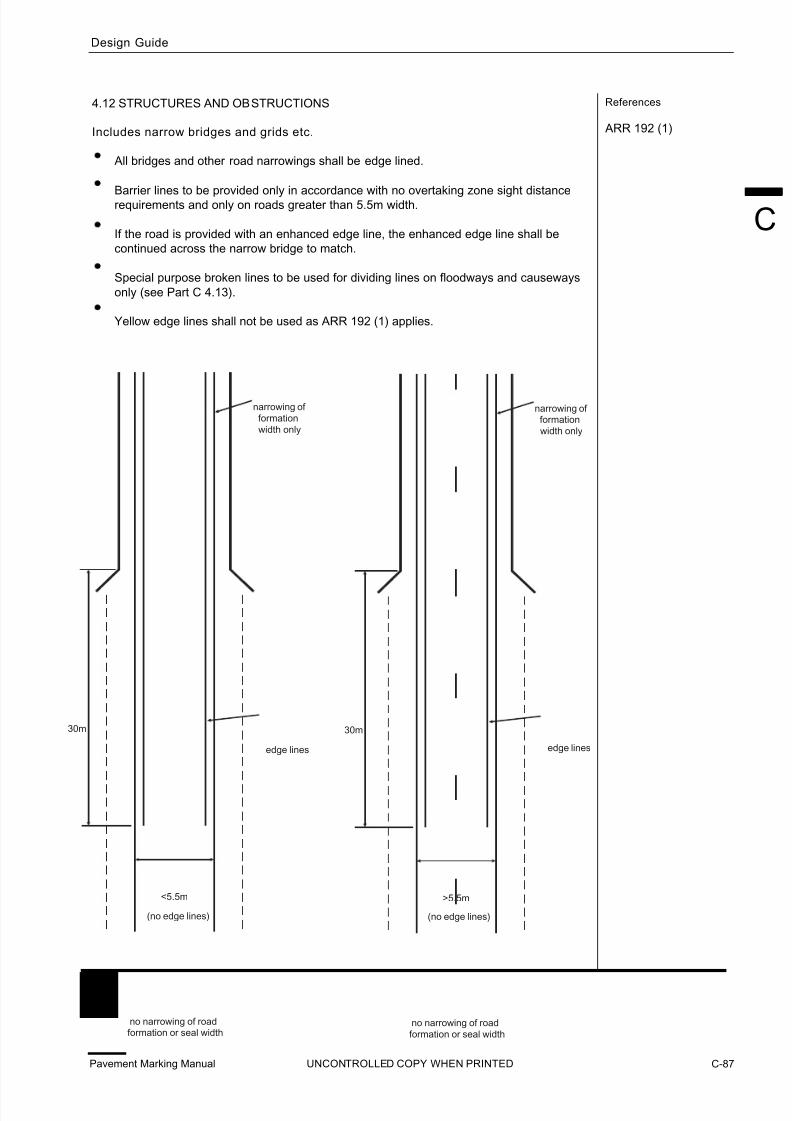
7/25/2019 Road Marking Guidelines
http://slidepdf.com/reader/full/road-marking-guidelines 157/159
Pavement Marking Manual C-87
C
Design Guide
UNCONTROLLED COPY WHEN PRINTED
References
ARR 192 (1)
4.12 STRUCTURES AND OBSTRUCTIONS
Includes narrow bridges and grids etc.
All bridges and other road narrowings shall be edge lined.
Barrier lines to be provided only in accordance with no overtaking zone sight distancerequirements and only on roads greater than 5.5m width.
If the road is provided with an enhanced edge line, the enhanced edge line shall be
continued across the narrow bridge to match.
Special purpose broken lines to be used for dividing lines on floodways and causeways
only (see Part C 4.13).
Yellow edge lines shall not be used as ARR 192 (1) applies.
30m
narrowing of formation
width only
edge lines
>5.5m
no narrowing of road
formation or seal width
30m
narrowing of
formation
width only
edge lines
<5.5m
no narrowing of roadformation or seal width
(no edge lines) (no edge lines)

7/25/2019 Road Marking Guidelines
http://slidepdf.com/reader/full/road-marking-guidelines 158/159
Pavement Markings ManualC-88
Design Guide
UNCONTROLLED COPY WHEN PRINTED
ReferencesGrid example
edge lines
>6.8m
narrowing of road formation and/or seal width
100mminimum
existing roadedge line if provided
narrowing of sealed width
grid
(edge lined)

7/25/2019 Road Marking Guidelines
http://slidepdf.com/reader/full/road-marking-guidelines 159/159