Road Engineering & Geotechnical Branch, JKR Ir. Liew · PDF fileRoad Engineering &...
47
Road Engineering & Geotechnical Branch, JKR Ir. Liew Shaw Shong 22 September 2014
Transcript of Road Engineering & Geotechnical Branch, JKR Ir. Liew · PDF fileRoad Engineering &...

Road Engineering & Geotechnical Branch, JKRIr. Liew Shaw Shong
22 September 2014

Section 71 of the Street, Drainage & Building Act, 1974
Misconstruction / Lack of Supervision
RM500,000 / 10 Years Imprisonment
Engineering Purposes
Strength to take imposed static & dynamic Stresses
Stiffness to control DeformationPermeability Characteristics
Collapsibility of Soil Matrix Structure
ErodibilityAvailability of Materials
Efforts needed for Economical & Efficient Compaction

What is Compaction?

?
?
?


?
Terminology
Lift (Max. thickness per lift subject to materials and compaction equipment)(1st Layer or 1st Lift)
(2nd Layer or 2nd Lift)
(3rd Layer or 3rd Lift)

Suitability of Fill Materials
Availability of Materials & Engineering solutions
Engineering Characteristics of MaterialsStrength, Stiffness, Permeability, Collapsibility &
ErodibilityParticle sizes, Grading, Plastic Index, Liquid Limit,
Slakability, Toughness, Hardness
Efforts needed for Economical & Efficient Compaction
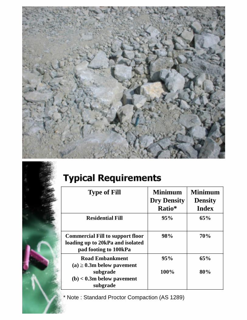
Type of Fill Minimum Dry Density
Ratio*
Minimum Density Index
Residential Fill 95% 65%
Commercial Fill to support floor loading up to 20kPa and isolated
pad footing to 100kPa
98% 70%
Road Embankment(a) 0.3m below pavement
subgrade(b) < 0.3m below pavement
subgrade
95%
100%
65%
80%
* Note : Standard Proctor Compaction (AS 1289)

Method Specifications
End Product Specifications
Performance Specifications
Too Wet
- Excessive Consolidation Settlement
- Low Strength
- Plastic Fill
Too Dry
- Vulnerable to Collapse Settlement
- Brittle Fill
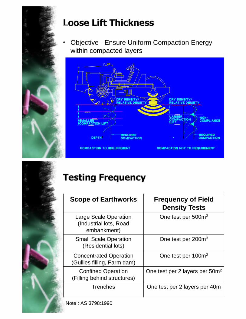
Objective - Ensure Uniform Compaction Energy within compacted layers
Scope of Earthworks Frequency of Field Density Tests
Large Scale Operation(Industrial lots, Road
embankment)
One test per 500m3
Small Scale Operation(Residential lots)
One test per 200m3
Concentrated Operation(Gullies filling, Farm dam)
One test per 100m3
Confined Operation(Filling behind structures)
One test per 2 layers per 50m2
Trenches One test per 2 layers per 40m
Note : AS 3798:1990

Whenever soil is placed as an engineering fill, it is normally compacted to a dense state, so as to obtain satisfactory engineering properties
Control of the degree of compaction is necessary to achieve a satisfactory result at reasonable cost
Laboratory compaction tests provide the basis for procedures used on site
Laboratory and Field Tests
Stage Tests Purpose
Stage 1 Proctor Test or Vibrating Hammer
To obtain maximum dry density and optimum moisture contentof fill soil material
Stage 2 Trial Compaction(First time trial and error of FDT test at site to determine compaction effort)
Stage 3Field Density Tests (FDT - Sand replacement method) & Moisture Content
Compare compacted field dry density to maximum dry density

Laboratory and Field Tests
Proctor Tests by R.R. Proctor (1920)Compaction effort (energy)Soil typesWater contentDry unit weight

Adopted Standards for Compaction Tests
Standard Proctor Test OR Modified Proctor Test?
1)Standard Proctor Test(2.5 kg rammer)
2)Modified Proctor Test(4.5 kg rammer)

2.5 kg or 4.5 kg rammer? (BS 1377-4:1990)
Maximum size of bulk soil particle?
Fine grain Medium-gravel size Coarse-gravel size
Percentage (%) of passing 37.5mm sieve and 20mm sieve?

Size of Mould?
1L mould or CBR mould? (BS 1377-4:1990)
1L mouldMould Volume =1000 mm3
CBR mouldMould Volume = 2305 mm3

Soil particles susceptible to crushing (deform)during compaction?Grading
ZoneMinimum percentagepassing test sieves
Minimum mass ofprepared soil required
Type of mould used
20 mm 37.5 mm NO YES(1) 100 % 100 %
6 kg 15 kg 1L(2) 95 % 100 %(3) 70 % 100 %
15 kg 40 kg CBR(4) 70 % 95 %(5) 70 % 90 %(X) < 70 % < 70 % TEST NO APPLICABLE
NO Soil particles not susceptible to crushing during compaction.
YES Soil particles susceptible to crushing during compaction.
Soil particles susceptible to crushing (deform) during compaction? (BS 1377-4:1990)
NO Soil particles not susceptible to crushing during compaction.
YES Soil particles susceptible to crushing during compaction.
of
of
of
of

BS 1377-4:1990: Summary of Preparation Method for Compaction Tests
Layers and time of rammer blows? (BS 1377-4:1990)
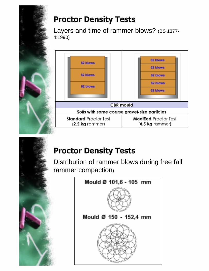
Layers and time of rammer blows? (BS 1377-4:1990)
Distribution of rammer blows during free fall rammer compaction)

Cautious notes
> 6 mm on top of mouldafter compaction
Void in the mould after compaction
< 6 mm on top of mouldafter compaction
REJECT REJECT OK
Repeat minimum 5 times whole mouldcompaction.
Obtain moisture content of each soil samples
Compute the bulk density, (in Mg/m3), of each compacted specimen:-
Compute the dry density, d (in Mg/m3), of each compacted specimen

0 10 20 30Moisture Content, w (%)
1.2
1.6
2
2.4
2.8
4.5kg Rammer
2.5kg Rammer
d = w Gs(1 - A)/(1 + w Gs)

Plot Dry Density vsMoisture Content curve
Plot 0%, 5%, 10% of Saturation Line
Determine:-1) Maximum Dry
Density (Mg/m3)2) Optimum
moisture Content (%)

Source: ELE International
IMPORTANT NOTE :Always check the
moisture content(s) are in acceptable range?

Comparison of compaction on dry side .vs. wet side
Factors consideredCharacteristic of compaction equipment
Weight and sizeOperation frequency and frequency range
Soil CharacteristicInitial densitySoil typeSize and shape of soil particleMoisture Content
Compaction ProcedureNo. of passes of the rollerLayer thicknessFrequency of operation of vibratorTowing speed

Scale of compaction?Large earthwork platform ?Beside Retaining Structures?Confined space?
Source of bulk filling material?Imported bulk filling material?Cut material (borrow pit) within site?
Compaction equipmentSmooth wheel roller (400kPa)Rubber tire roller (700kPa)Sheepsfoot roller (1.4 to 7MPa)Tamping foot roller (1.4 to 8.4MPa)Grid roller (1.4 to 6.2 MPa)Vibrating plateDynamic compactionVibrocompaction

To determine the compaction effort (no of passes) and loose lift thickness for compaction at site.
Description Compactor Capacity Typical valueNo of passes 20-30 tonne roller
compactorstart 6 passes (e.g.: 6, 8,10, 12, 14 passes)
1 tonne roller compactor Start 20 passes (e.g.: 20, 22, 25 passes)
Loose lift thickness
20-30 tonne roller compactor
400 mm 500 mm
1 tonne roller compactor 200 mm 300 mm

Trial Compaction
Test no.Dry
Density (Mg/m3)
Maximum Dry
Density (Mg/m3)
Compaction Achieved (%)
Moisture Content
(%)*
No. of Passes
Thickness of Fill, (mm)
FD1 1.527 1.734 88.1 16.29 6 passes 500
FD2 1.443 1.734 83.2 16.81 8 passes 500
FD3 1.433 1.734 82.6 17.1 10 passes 500
FD4 1.659 1.736 95.6 14.67 6 passes 450
FD5 1.641 1.736 94.5 15.45 8 passes 450
FD6 1.63 1.736 93.9 16.48 10 passes 450
8 passes with maximum loose lift thickness of 450mm are established from Trial Compaction
To obtain field dry density after compaction.
Verification test / control test for quality of compaction.


Determine moisture content at laboratory (Oven or Microwave Oven)
Determine moisture content at field (Speedy Tester)

Scope of Earthworks Frequency of Field Density Tests
Large Scale Operation(Industrial lots, Road
embankment)
One test per 500m3
Small Scale Operation(Residential lots)
One test per 200m3
Concentrated Operation(Gullies filling, Farm dam)
One test per 100m3
Confined Operation(Filling behind structures)
One test per 2 layers per 50m2
Trenches One test per 2 layers per 40m
Note : AS 3798:1990

Numbering sequence of FDT (no repeat of naming)
Reduced level (Important: to check thickness of lift)
Moisture Content (Important: must be in the reasonable range of fill soil type)
Passed 95% of relative density of Standard Proctor Test?
Sieve analysis should be included together with Proctor Test (for soil with gravels).
Plasticity Index to test for clay existence in bulk soil as fill material.


Standard Proctor Test Results
Some results
95.2 96.0 95.5 95.2 95.2 95.2 95.3 95.1 95.3 95.3 95.4 95.0

Summary of compaction test :-2010 Nos of FDT done.FDT test generally consistence.Good record of FDT points (Zoning, etc) except for typo error.Only issue - Crusher run with higher moisture content redo Standard Proctor Test to verify moisture content by independent laboratory.
Backfilling works at RC Retaining Wall (Inverted-L)

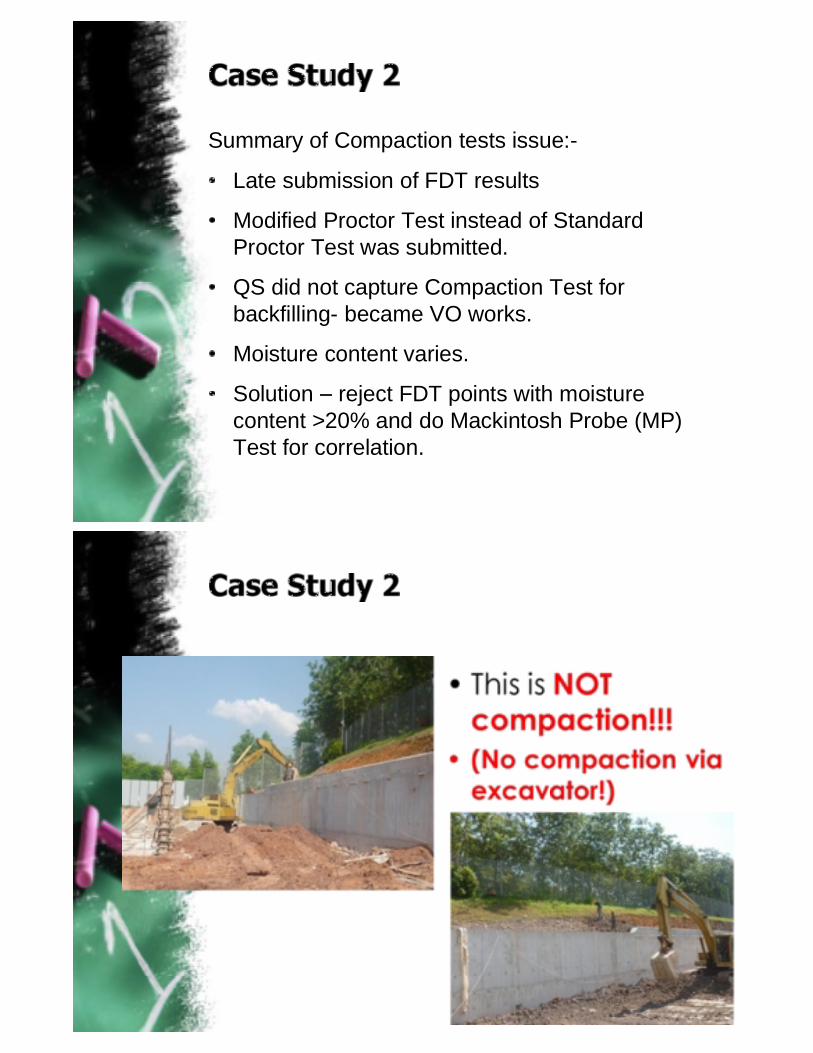
Summary of Compaction tests issue:-
Late submission of FDT results
Modified Proctor Test instead of Standard Proctor Test was submitted.
QS did not capture Compaction Test for backfilling- became VO works.
Moisture content varies.
Solution reject FDT points with moisture content >20% and do Mackintosh Probe (MP) Test for correlation.
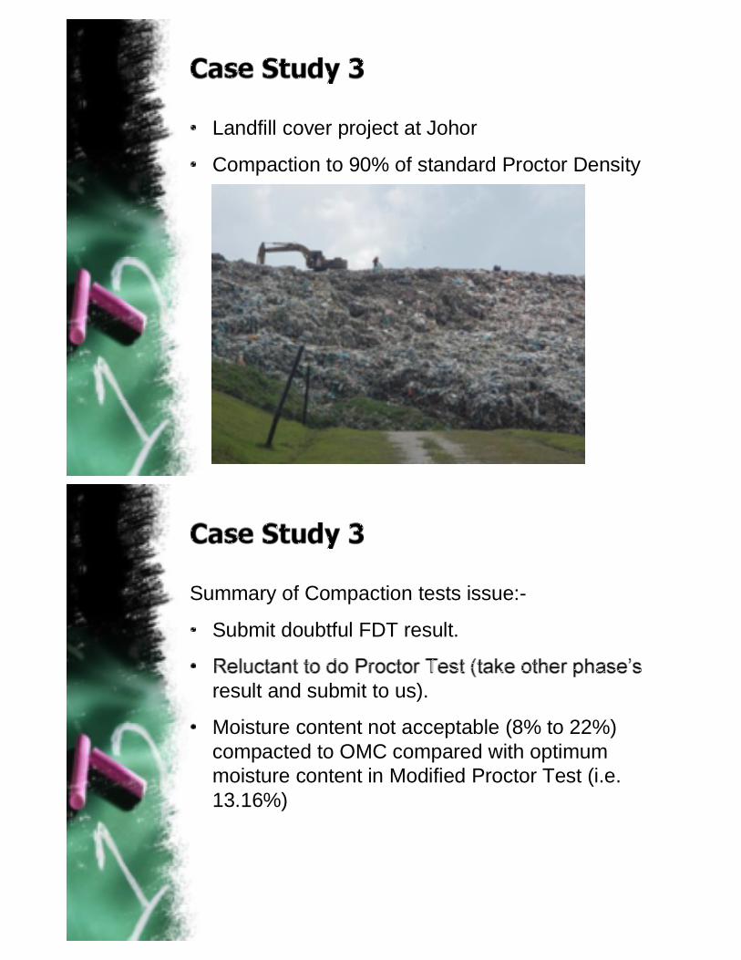
Landfill cover project at Johor
Compaction to 90% of standard Proctor Density
Summary of Compaction tests issue:-
Submit doubtful FDT result.
result and submit to us).
Moisture content not acceptable (8% to 22%) compacted to OMC compared with optimum moisture content in Modified Proctor Test (i.e. 13.16%)

Solution:-
Do trial pit and re-do FDT test.
Do Mackintosh Probe Test for correlation.
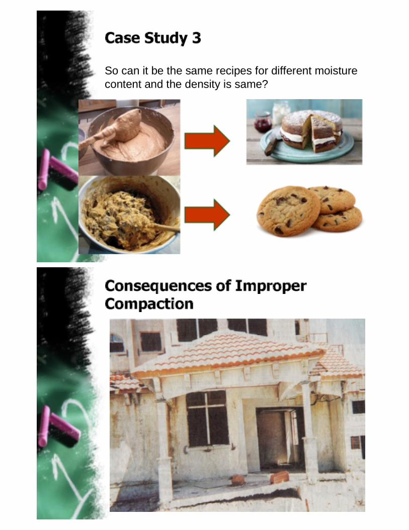
So can it be the same recipes for different moisture content and the density is same?

Weak Strength
Tension Cracks
Leaking Pipe
Tilting
Leaking Water
Original Ground
Leaking Water
Instability (Creeping Movement)
Distortion
3m
1.51
1.51
Lateral MovementSettlement

Gap (75mm)
Void (150mm)
Total/Differential Platform Settlement
Differential Settlement
Depressions

Differential Settlement
Shear Cracks
Differential Settlement
Shear Cracks
Sagging

Poor Compaction
or Thin Fill
Poor Compaction
or Thin Fill
Very Poor Compaction
or Thick Fill
Fill Settlement Fill SettlementExcessive Fill
Settlement
Weep Hole Drain
Shear Cracks
Cast-In-Situ R.C. Monsoon Drain
Collapse Settlement of New Fill

Collapse Settlement of New Fill
Downdrag on Pile
Downdrag from Piles
Structural Cracks

Erosion of DrainHigh Permeability of Poorly Compacted
Soil by Surface Runoff
Consideration of compaction pressure in a restrained condition
h v
ka
Retaining Structure
Earth Pressure Envelope including Compaction Effort
Retaining Structure
Earth Pressure Envelope without Compaction EffortKa

Distance from Wall
Resultant Pressure Distribution from Compaction Effort
Retaining Structure
Distance from Wall
Retaining Structure
Minimum 1.5 m away from face of wall
Each fill material shall have own compaction test as referenceOnly specify the actual required compaction effort or reasonable compaction practiceControls on loose lift thickness, moisture content at placement & particle sizeField tests with sufficient statisticsLight compaction on last layer to prevent rain water ingressionCompaction pressureSupervision
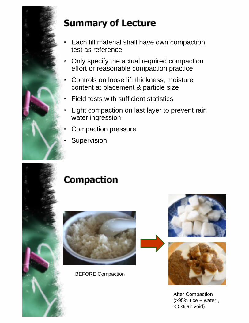
BEFORE Compaction
After Compaction(>95% rice + water , < 5% air void)