Road Corridor Planning
58
City of Ottawa Road Corridor Planning & Design Guidelines URBAN & VILLAGE COLLECTORS RURAL ARTERIALS & COLLECTORS DELCAN Corporation The Planning Partnership October 2008
-
Upload
azharudin-zoechny -
Category
Documents
-
view
25 -
download
0
description
Urban planning sample
Transcript of Road Corridor Planning
City of Ottawa Road Corridor Planning & Design Guidelines URBAN & VILLAGE COLLECTORS
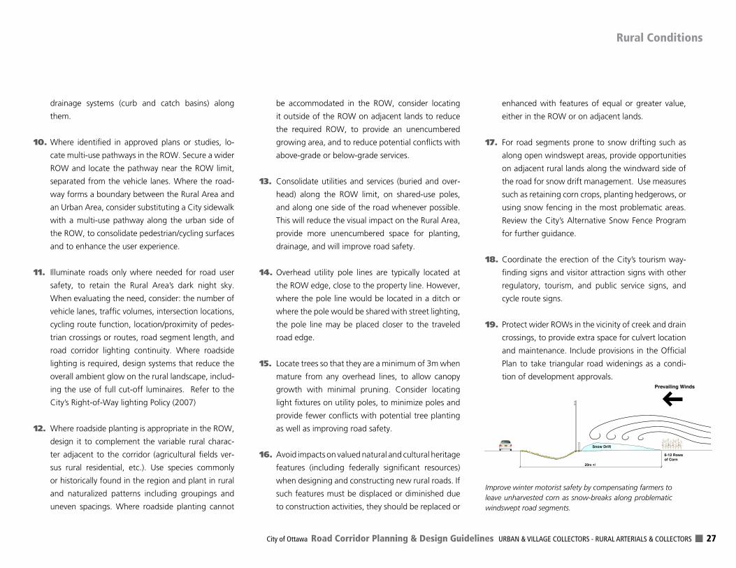
RURAL ARTERIALS & COLLECTORS
DELCAN CorporationThe Planning Partnership
October 2008
City of Ottawa Road Corridor Planning & Design Guidelines URBAN & VILLAGE COLLECTORS - RURAL ARTERIALS & COLLECTORS 1
Contents
1.0 Introduction ................................................................................... 2
2.0 Utility & Role of the Guidelines ................................................. 4
3.0 Study Process & Stakeholder Involvement ............................. 5
4.0 The Basis for Sustainable Road Corridors .............................. 6
5.0 Planning & Design Guidelines for Corridor Components ...... 10
6.0 Rural Conditions ......................................................................... 26
7.0 A Road Typology ........................................................................ 28
8.0 Green Streets ............................................................................... 33
9.0 Implementation .......................................................................... 36
APPENDIX A: Demonstration Cross-sections & Right-of-way Width Requirements ....................... 39
APPENDIX B: Road Design SpecificationGuidelines ......................................... 55
List of Photos ....................................................................................... 57
Council Approved on March 26, 2008
DELCAN Corporation - The Planning Partnership 2
Introduction
1.0
The City of Ottawa continues to show leadership in the
pursuit of sustainable urban transportation. Its award-
winning Regional Road Corridor Design Guidelines (2000)
has been widely referenced in urban transportation re-
search across Canada. Those guidelines were pioneering
in their recognition that Arterial Roads play a pivotal role
in shaping the public space and landscape character of
a City, while providing mobility choices, accessibility, and
space for vital City services and utilities. The document
had a strong influence on the ensuing City of Ottawa Of-
ficial Plan (2003). The guidelines remain highly relevant
today and continue to guide the construction and retro-
fit of the City’s Arterial Road network.
As a follow-on project, the City has now prepared these
guidelines which address the following roads as classi-
fied in the Official Plan:
1. Major Collector and Collector Roads in the Urban
Area and Villages; and,
2. Arterial Roads and Collector Roads in the Rural
Area.
Major Collector and Collector Roads in the Urban
Area, Rural Area, and Villages are designated in the Of-
ficial Plan (Annex 1, Section 1.0) to:
1. Connect communities and distribute traffic between
the arterial system and the local road system;
2. Act as shorter links (than Arterial Roads);
3. Provide direct access to adjacent properties where
such access will not introduce traffic safety or capacity
concerns;
4. Accommodate the safe and efficient operation of
transit services;
5. Be the principal streets in urban and Village neigh-
bourhoods;
6. Be used by local residents, delivery and commercial
vehicles, transit and school buses, cyclists, and pedes-
trians;
7. Operate with reduced speed and volume of traffic
(than Arterial Roads);
8. Be more accommodating (than Arterial Roads) for cy-
clists and pedestrians; and,
9. Include tree plantings, bus stops, community mailbox-
es and other streetscape features to create roadways
that are integrated with their neighbourhood.
Designated “Major” Collectors act as a connection be-
tween Arterial Road and Collector Roads. Higher traffic
volumes and a greater mix of vehicle types and sizes are
to be accommodated than compared to Collector Roads.
There are no Major Collectors designated in the Rural
Area or Villages.
Arterial Roads are the major roads of the City desig-
nated to carry large volumes of traffic over the longest
distances. This system provides links to provincial and in-
ter-provincial roads. Vehicular access to adjacent proper-
ties should be controlled to reduce turning movements
and potential conflicts. Other than these principles, the
Official Plan’s Road Classification system provides little
guidance on the planned characteristics of Arterial Roads
in the Rural Area.
It is important to note that the Regional Road Corridor
Design Guidelines addressed Arterial Roads in the Urban
Area and those with a “mainstreet” function in the Vil-
lages. The City of Ottawa has also completed urban de-
sign guidelines for Arterial Mainstreets and Traditional
Mainstreets through its Ottawa by Design program. No
further design guidance for mainstreets in Villages is pro-
vided in this document.
This document will also be highly valued in guiding the
design of these important Roads throughout its vast
2,700+ square kilometres of urban, village and rural
communities.
City of Ottawa Road Corridor Planning & Design Guidelines URBAN & VILLAGE COLLECTORS - RURAL ARTERIALS & COLLECTORS 3
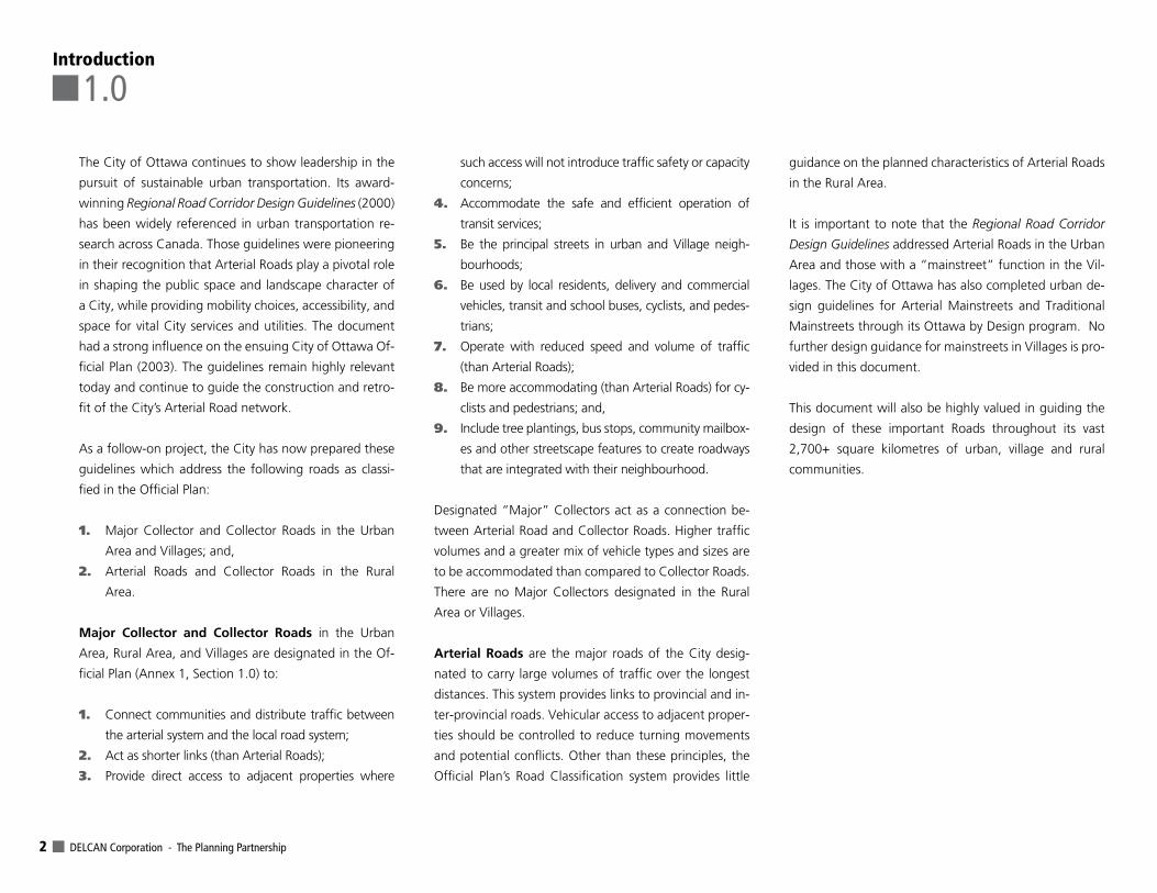
Above: Urban Road NetworkBelow: Central Area Network
Left: Rural Road Network
Introduction
1-1
1-2
DELCAN Corporation - The Planning Partnership 4
As with the Regional Road Corridor Design Guidelines,
these guidelines are to be used by anyone involved in
the planning and design of new collector and rural Arte-
rial Roads, or their reconstruction. This includes munici-
pal staff and elected officials, citizens, community and
interest groups, developers, and design professionals in
various disciplines. The guidelines are to be used in the
following circumstances:
> The preparation and review of Community Design
Plans;
> The design and review of Plans of Subdivision;
> The implementation of Zoning By-Laws and Site
Plans;
> The design of Roads to be constructed new, recon-
structed or rehabilitated; and,
> The selection and harmonization of appropriate
right-of-way (ROW) protection policies in the City’s
next update of its Official Plan.
It is important to note that the guidelines are not in-
tended to be an encyclopedic “how-to” design manual.
Their role is simply to provide general design guidance,
acknowledging that some of the concepts and dem-
onstrations require detailed design investigations, and
may not be achievable in all circumstances. They do not
constitute city standards, although they may inform the
continual evolution of standards. On this basis, the role
of the document is to focus on key design elements and
cross-section demonstrations that are specific to the road
types in question and that introduce new thoughts and
ideas that are important to the Ottawa context and not
referenced in other related documents. These other sup-
porting documents include, but are not limited to (listed
alphabetically):
> Context Sensitive Solutions in Designing Major Ur-
ban Thoroughfares for Walkable Communities: An
ITE Proposed Recommended Practice (ITE, 2006);
> Environmental Noise Control Guidelines (City of Ot-
tawa, 2006);
> Geometric Design Guide for Canadian Roads (Trans-
portation Association of Canada, 1999);
> Geometric Design Standards for Ontario Highways
(Ontario Ministry of Transportation);
> Greening Guidelines for Regional Roads (Regional
Municipality of Ottawa-Carleton, 1992);
> Ottawa Cycling Plan [Draft] (City of Ottawa, 2005);
> Pedestrian Plan (City of Ottawa, In-Process 2007);
> Promoting Sustainable Transportation Through Site
Design: An ITE Proposed Recommended Practice (In-
stitute of Transportation Engineers, 2004);
> Postal Delivery Standards Manual (Canada Post,
2004);
> Right-of-Way Cross Sections for New Residential
Roads [Memo] (City of Ottawa, 2007);
> Right-of-Way Lighting Policy (City of Ottawa,
2007);
> Rural Pathways Plan (Stantec Consulting Ltd. &
Stonestable Consulting, 2006);
> Street Design Policy Special Streets (City of Ottawa,
2006);
> Tree Planting Advice (Hydro Ottawa);
> Urban Design Guidelines for Arterial Mainstreets
(City of Ottawa, 2006);
> Urban Design Guidelines for Greenfield Neighbour-
hoods [Draft] (City of Ottawa, 2007);
> Urban Design Guidelines for Traditional Mainstreets
(City of Ottawa, 2006); and,
> Utility Coordination Committee Guidelines and Poli-
cies (City of Ottawa, Ongoing).
It is also important to consider the Regional Road Cor-
ridor Design Guidelines as a companion document. Al-
though those guidelines address designated Arterial
Roads, which are the major roads of the City, much of
the design guidance is relevant to urban Major Collector
and Collector Roads and there is no need to reinvent
or re-package the information. Where new ideas and
other innovations have emerged, these are documented.
For specific technical design issues, reference should be
made to City of Ottawa Standard Tender Documents,
Volumes I and II.
These guidelines are presented in a format that is simple,
succinct, user-friendly, broadly accessible, and focused
on select matters of concern for these road corridors
both today and in the future.
Utility & Role of the Guidelines
2.0
City of Ottawa Road Corridor Planning & Design Guidelines URBAN & VILLAGE COLLECTORS - RURAL ARTERIALS & COLLECTORS 5
These guidelines have benefited from the input of a
Working Group that was formed for the project. This
group helped to identify matters of concern that are ad-
dressed in the document. Their input was highly appreci-
ated. Participants included representation from:
> Various City of Ottawa departments;
> Community Associations;
> Homebuilders and Land Developers;
> Other consultants; and,
> Interest Groups.
The group met during the course of the study and pro-
vided input in a round-table setting. Minutes were cir-
culated and follow-on discussions were held. Other
matters were introduced through individual submissions
and small group meetings. Additional comments were
received during a Public Open House in June, 2007, and
the draft Guidelines were circulated for broad public re-
view. Adjustments were made to reflect this input.
In addition to the Working Group input, the study con-
sultants and City staff carried out a best practices scan.
This included a review of related documents from several
agencies and jurisdictions. As is often the case, some of
the best practices originated in Ottawa and have been
included in the guidelines.
Study Process & Stakeholder Involvement
3.03-1
3-2
DELCAN Corporation - The Planning Partnership 6
The underlying basis of these road corridor design guide-
lines is set out in the City’s Official Plan (2003). The de-
sign objectives vary depending on whether the land use
context is urban, Village, or rural in nature. This is con-
sistent with the recent emphasis in transportation plan-
ning on “Context Sensitive Solutions”, “Smart Growth”,
and “Sustainable Infrastructure”.
4.1 OfficialPlanDirectionThe Official Plan’s Guiding Principles (Section 1.6) and
Strategic Directions (Section 2.0) specifically-related to
these guidelines are to:
> Build a transportation system that emphasizes tran-
sit, walking and cycling;
> Design attractive communities where buildings,
open space and transportation work well together;
> Build communities that are easy to get around and
barrier-free for the disabled;
> Develop a green City with a network of open spaces
and to recognize that trees are an important way of
maintaining environmental integrity;
> Provide a range of mobility choices and accessibility
options;
> Pursue land use patterns that reduce the need to
travel;
> Reduce the amount of land used for new transpor-
tation facilities;
> Ensure the provision of facilities for pedestrians
and cyclists in the construction or reconstruction of
roadways;
> Minimize capital and operating costs, ensure relia-
bility of level of service, and mitigate environmental
impacts of infrastructure;
> Reduce air pollution and greenhouse gas emissions
from private automobile use;
> Reduce traffic;
> Reduce Road construction disruption; and,
> Accommodate the movement of people during
peak hours.
The Official Plan’s targets (Section 2.3.1) for the modal
share distribution of peak-hour trips are 10% walking,
3% cycling, and 30% transit by the year 2021.
Section 4.3 of the Official Plan also establishes the poli-
cies used to review development applications that relate
to walking, cycling, transit and roads. Key policies related
to this study include:
> On new plans of subdivision, provide the opportu-
nity for direct transit routes through a community
and require all buildings to be within 400m walking
distance of a transit stop;
> Provide sidewalks on both sides of Arterial Roads,
Major Collector and Collector Roads in the Urban
Area and Villages; and,
> Provide a sidewalk or multi-use pathway on at least
one side of all roads in the Urban Area that serve
transit.
The design of the City’s Major Collector and Collector
Roads in the Urban Area and the Arterial and Collector
Roads in the Rural Area must be consistent with this Of-
ficial Plan direction.
The Basis for Sustainable Road Corridors
4.0
City of Ottawa Road Corridor Planning & Design Guidelines URBAN & VILLAGE COLLECTORS - RURAL ARTERIALS & COLLECTORS 7
4.2 Pursuing Sustainable InfrastructureFurther to the Official Plan’s guiding principle of a green
and environmentally-sensitive City, the following ten
(10) additional criteria should also be considered in the
pursuit of smart and sustainable infrastructure solutions
for road corridors in Ottawa. These criteria reflect current
thinking. Road designs should:
1. Be financially sustainable to construct and main-
tain;
2. Minimize the use of land;
3. Be efficient to maintain over their life-cycle;
4. Emphasize green living elements for oxygen produc-
tion, carbon dioxide consumption, and many other
benefits;
5. Provide infiltration opportunities for storm water,
and retain water for living materials;
6. Reduce waste associated with construction and
maintenance activities;
7. Use recycled materials where feasible;
8. Preserve and conserve existing infrastructure where
practical;
9. Lead to the remediation of unfavourable environ-
mental conditions; and,
10. Engage stakeholders and respond to their current
and future needs.
Ottawa’s urban collectors and rural roads should advance
environmental quality by showcasing a range of sustain-
able infrastructure innovations. They are excellent candi-
dates for incentive-based or pilot infrastructure projects
such as:
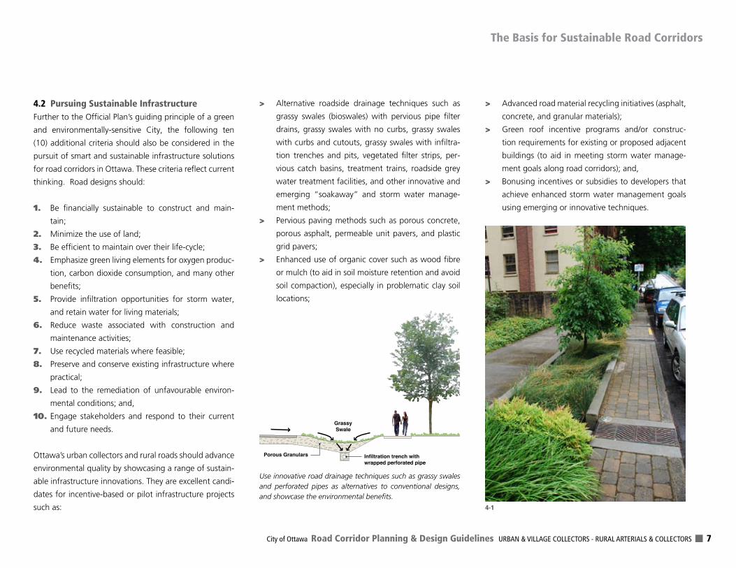
> Alternative roadside drainage techniques such as
grassy swales (bioswales) with pervious pipe filter
drains, grassy swales with no curbs, grassy swales
with curbs and cutouts, grassy swales with infiltra-
tion trenches and pits, vegetated filter strips, per-
vious catch basins, treatment trains, roadside grey
water treatment facilities, and other innovative and
emerging “soakaway” and storm water manage-
ment methods;
> Pervious paving methods such as porous concrete,
porous asphalt, permeable unit pavers, and plastic
grid pavers;
> Enhanced use of organic cover such as wood fibre
or mulch (to aid in soil moisture retention and avoid
soil compaction), especially in problematic clay soil
locations;
> Advanced road material recycling initiatives (asphalt,
concrete, and granular materials);
> Green roof incentive programs and/or construc-
tion requirements for existing or proposed adjacent
buildings (to aid in meeting storm water manage-
ment goals along road corridors); and,
> Bonusing incentives or subsidies to developers that
achieve enhanced storm water management goals
using emerging or innovative techniques.
The Basis for Sustainable Road Corridors
Porous Granulars
GrassySwale
Infiltration trench with wrapped perforated pipe
Use innovative road drainage techniques such as grassy swales and perforated pipes as alternatives to conventional designs, and showcase the environmental benefits.
4-1
DELCAN Corporation - The Planning Partnership 8
4.3 Functional Objectives for Collector Roads in Urban Areas & VillagesThe following are the functional objectives for road cor-
ridors in the Urban Area and in Villages:
Urban Fabric: establish the spatial organization and fab-
ric of a community and express its visual character and
identity.
Community Connector: create identifiable corridors
that connect uses within a community as well as con-
necting the community to the Arterial Road system, and
other communities.
Public Space: serve as an important public space that
can accommodate pedestrian activity and social interac-
tion in a safe and comfortable environment.
Green Space: form part of the green and sustainable
imprint of a community as well as being tree-lined routes
linking open spaces. They should also be capable of ac-
commodating multi-use pathways as part of the City’s
Greenspace Network, located in green and open space
settings, where designated in the Official Plan.
Access Provider: provide access to individual properties
in accordance with their roadway classification designa-
tion, with the frequency of access being dependant on
the context as well as traffic safety and capacity consid-
erations.
Multi-Modal Route: safely and efficiently provide for
movement in all modes, with an emphasis on walking,
cycling, transit use, along with private automobiles and
service vehicles.
Goods Movement: provide for movement of goods and
materials carried in a range of vehicle types, particularly
those roads designated by the City as Truck Routes.
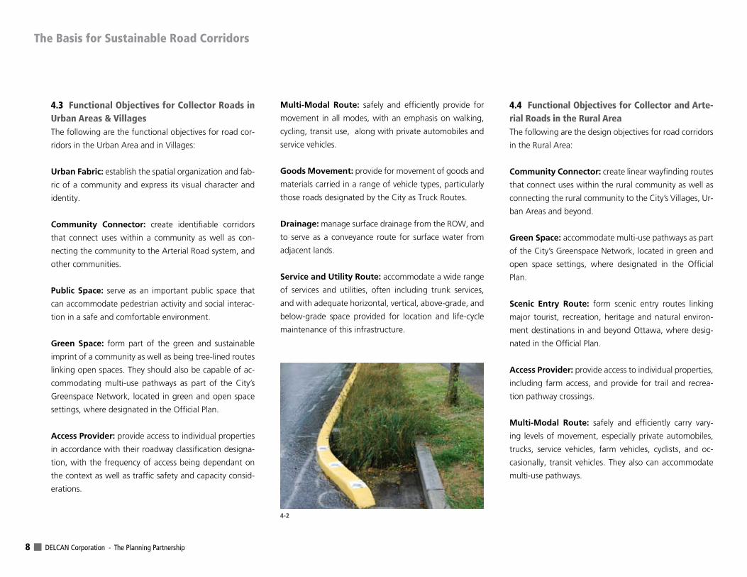
Drainage: manage surface drainage from the ROW, and
to serve as a conveyance route for surface water from
adjacent lands.
Service and Utility Route: accommodate a wide range
of services and utilities, often including trunk services,
and with adequate horizontal, vertical, above-grade, and
below-grade space provided for location and life-cycle
maintenance of this infrastructure.
4.4 Functional Objectives for Collector and Arte-rial Roads in the Rural AreaThe following are the design objectives for road corridors
in the Rural Area:
Community Connector: create linear wayfinding routes
that connect uses within the rural community as well as
connecting the rural community to the City’s Villages, Ur-
ban Areas and beyond.
Green Space: accommodate multi-use pathways as part
of the City’s Greenspace Network, located in green and
open space settings, where designated in the Official
Plan.
Scenic Entry Route: form scenic entry routes linking
major tourist, recreation, heritage and natural environ-
ment destinations in and beyond Ottawa, where desig-
nated in the Official Plan.
Access Provider: provide access to individual properties,
including farm access, and provide for trail and recrea-
tion pathway crossings.
Multi-Modal Route: safely and efficiently carry vary-
ing levels of movement, especially private automobiles,
trucks, service vehicles, farm vehicles, cyclists, and oc-
casionally, transit vehicles. They also can accommodate
multi-use pathways.
The Basis for Sustainable Road Corridors
4-2
City of Ottawa Road Corridor Planning & Design Guidelines URBAN & VILLAGE COLLECTORS - RURAL ARTERIALS & COLLECTORS 9
Goods Movement: provide for movement of goods
and materials carried in heavy vehicles as well as farm
vehicles, particularly those Roads designated by the City
as Truck Routes.
Drainage: manage surface drainage from the ROW, and
in some cases, to manage overland drainage from adja-
cent rural lands.
Service and Utility Route: accommodate a limited
range of services and utilities, often including above-
grade utility poles, anchors and guys, and with adequate
horizontal, vertical, above-grade, and below-grade space
provided for location and maintenance of this infrastruc-
ture.
These objectives also apply to road segments within Vil-
lages at the rural-village fringe, with an added empha-
sis on pedestrian and cycling movements in the Village
context.
The Basis for Sustainable Road Corridors
DELCAN Corporation - The Planning Partnership 10
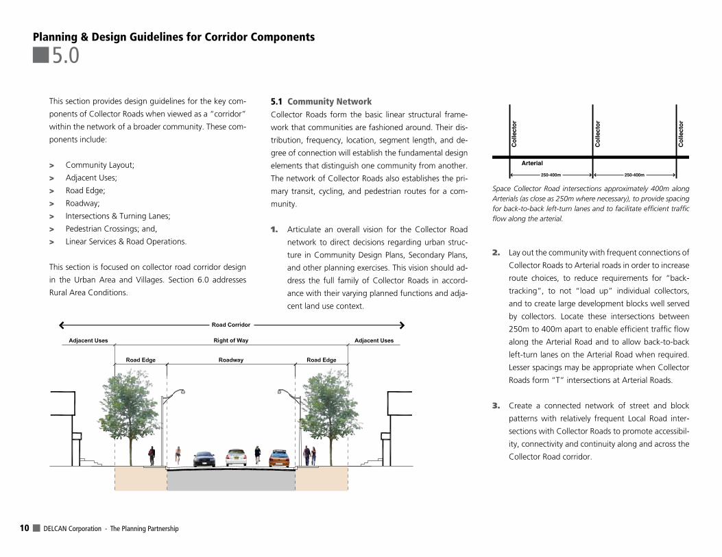
This section provides design guidelines for the key com-
ponents of Collector Roads when viewed as a “corridor”
within the network of a broader community. These com-
ponents include:
> Community Layout;
> Adjacent Uses;
> Road Edge;
> Roadway;
> Intersections & Turning Lanes;
> Pedestrian Crossings; and,
> Linear Services & Road Operations.
This section is focused on collector road corridor design
in the Urban Area and Villages. Section 6.0 addresses
Rural Area Conditions.
5.1 Community NetworkCollector Roads form the basic linear structural frame-
work that communities are fashioned around. Their dis-
tribution, frequency, location, segment length, and de-
gree of connection will establish the fundamental design
elements that distinguish one community from another.
The network of Collector Roads also establishes the pri-
mary transit, cycling, and pedestrian routes for a com-
munity.
1. Articulate an overall vision for the Collector Road
network to direct decisions regarding urban struc-
ture in Community Design Plans, Secondary Plans,
and other planning exercises. This vision should ad-
dress the full family of Collector Roads in accord-
ance with their varying planned functions and adja-
cent land use context.
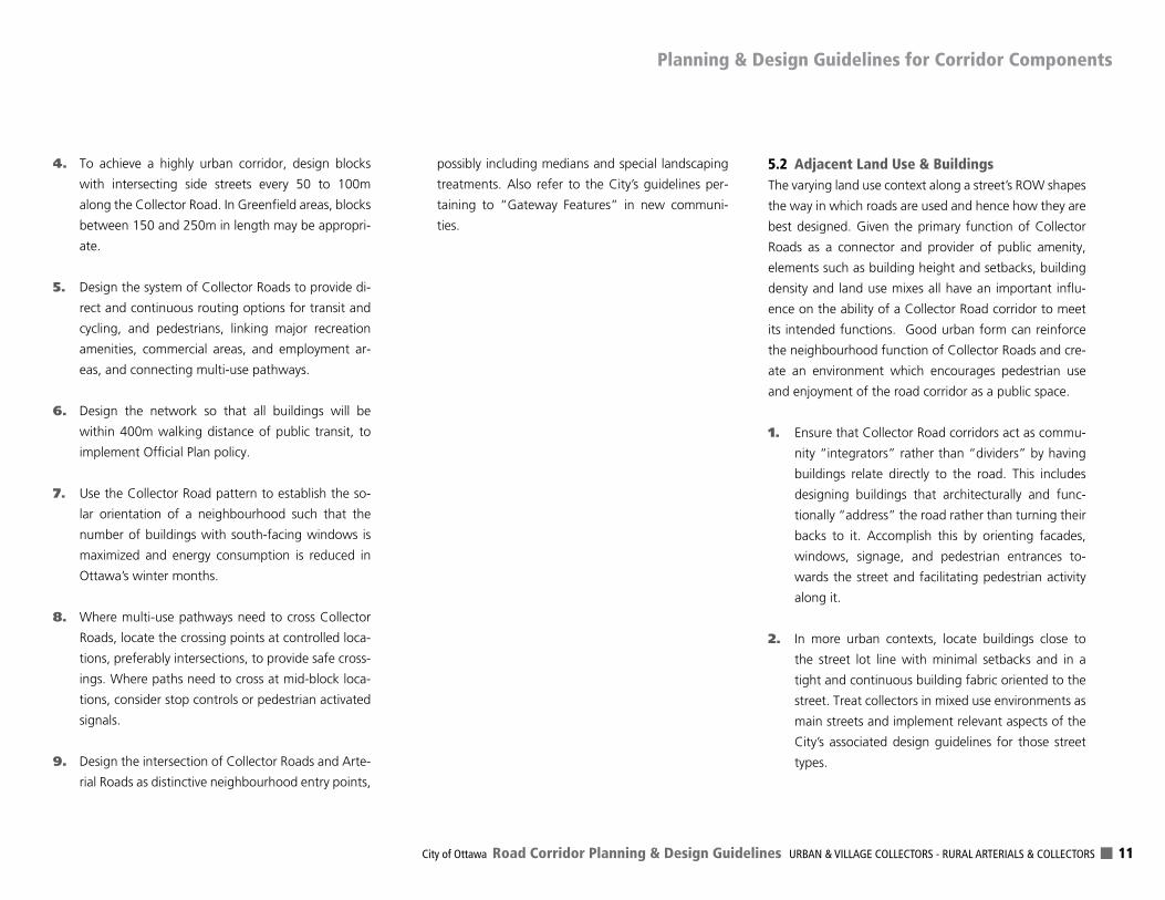
2. Lay out the community with frequent connections of
Collector Roads to Arterial roads in order to increase
route choices, to reduce requirements for “back-
tracking”, to not “load up” individual collectors,
and to create large development blocks well served
by collectors. Locate these intersections between
250m to 400m apart to enable efficient traffic flow
along the Arterial Road and to allow back-to-back
left-turn lanes on the Arterial Road when required.
Lesser spacings may be appropriate when Collector
Roads form “T” intersections at Arterial Roads.
3. Create a connected network of street and block
patterns with relatively frequent Local Road inter-
sections with Collector Roads to promote accessibil-
ity, connectivity and continuity along and across the
Collector Road corridor.
Planning & Design Guidelines for Corridor Components
5.0
250-400m 250-400m
Arterial
Col
lect
or
Col
lect
or
Col
lect
or
Space Collector Road intersections approximately 400m along Arterials (as close as 250m where necessary), to provide spacing for back-to-back left-turn lanes and to facilitate efficient traffic flow along the arterial.
City of Ottawa Road Corridor Planning & Design Guidelines URBAN & VILLAGE COLLECTORS - RURAL ARTERIALS & COLLECTORS 11
4. To achieve a highly urban corridor, design blocks
with intersecting side streets every 50 to 100m
along the Collector Road. In Greenfield areas, blocks
between 150 and 250m in length may be appropri-
ate.
5. Design the system of Collector Roads to provide di-
rect and continuous routing options for transit and
cycling, and pedestrians, linking major recreation
amenities, commercial areas, and employment ar-
eas, and connecting multi-use pathways.
6. Design the network so that all buildings will be
within 400m walking distance of public transit, to
implement Official Plan policy.
7. Use the Collector Road pattern to establish the so-
lar orientation of a neighbourhood such that the
number of buildings with south-facing windows is
maximized and energy consumption is reduced in
Ottawa’s winter months.
8. Where multi-use pathways need to cross Collector
Roads, locate the crossing points at controlled loca-
tions, preferably intersections, to provide safe cross-
ings. Where paths need to cross at mid-block loca-
tions, consider stop controls or pedestrian activated
signals.
9. Design the intersection of Collector Roads and Arte-
rial Roads as distinctive neighbourhood entry points,
possibly including medians and special landscaping
treatments. Also refer to the City’s guidelines per-
taining to “Gateway Features” in new communi-
ties.
5.2 Adjacent Land Use & BuildingsThe varying land use context along a street’s ROW shapes
the way in which roads are used and hence how they are
best designed. Given the primary function of Collector
Roads as a connector and provider of public amenity,
elements such as building height and setbacks, building
density and land use mixes all have an important influ-
ence on the ability of a Collector Road corridor to meet
its intended functions. Good urban form can reinforce
the neighbourhood function of Collector Roads and cre-
ate an environment which encourages pedestrian use
and enjoyment of the road corridor as a public space.
1. Ensure that Collector Road corridors act as commu-
nity “integrators” rather than “dividers” by having
buildings relate directly to the road. This includes
designing buildings that architecturally and func-
tionally “address” the road rather than turning their
backs to it. Accomplish this by orienting facades,
windows, signage, and pedestrian entrances to-
wards the street and facilitating pedestrian activity
along it.
2. In more urban contexts, locate buildings close to
the street lot line with minimal setbacks and in a
tight and continuous building fabric oriented to the
street. Treat collectors in mixed use environments as
main streets and implement relevant aspects of the
City’s associated design guidelines for those street
types.
Planning & Design Guidelines for Corridor Components
DELCAN Corporation - The Planning Partnership 12
3. Where direct driveway access is undesirable for traf-
fic safety reasons, use side-lotting and single loaded
side streets as techniques to achieve the desired
building orientation while providing for safe access
and adequate space for utilities. Front-lotting with
rear lane access may be appropriate in some circum-
stances such as within or near Mixed Use Centres
and Town Centres.
4. Avoid rear-lotting along Collector Roads. Front adja-
cent uses onto the roads and avoid conditions where
sound attenuation fences would be required.
5. Avoid locating street townhomes and narrow-lot
detached homes with front driveways along Collec-
tor Roads that would lead to an excessive number of
driveways and turning movements.
6. Avoid garages that protrude in front of the house
and ensure that driveways are not wider than the
garage. Use shared driveways where possible. De-
sign front porches and associated detailing to mini-
mize the effect of large garage doors along the
street.
7. Provide off-street parking and vehicle access to the
rear or side of buildings, using rear lanes where ap-
propriate. Buffer parking lots from the street with
dense landscape strips and/or low fences along the
street lot line on adjacent lands. Provide breaks in
the buffer to enable pedestrian routes from the
sidewalk into the parking lot.
8. Locate community serving uses such as schools,
community and neighbourhood parks, minor com-
mercial uses and places of worship with frontage
and orientation along collector streets and in loca-
tions that can become focal points for community
interaction. Site these buildings close to the street,
and with no parking located between the building
and the street.
9. Locate land uses requiring large lots (including me-
dium and high density uses served by private roads
or lanes) along Collector Roads to consolidate and
minimize driveway connections. Ensure that the
buildings address the road.
10. In the cases where a Collector Road separates signif-
icantly different land uses (i.e. residential from retail
or business park), tie the two street edges together
to maximize community integration. Accomplish
this through consistency in landscape treatment,
lighting, building setbacks, building orientation, and
signage.
11. Where a Collector Road corridor runs through or
adjacent to a Heritage Conservation District or a
federally significant area, and is requiring rehabilita-
tion, design the corridor elements (including street
lighting and street furniture) to reflect and reinforce
the characteristics of the district, and respect any
planning or design guidelines that may apply.
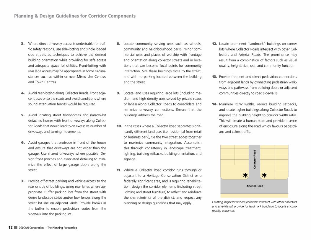
12. Locate prominent “landmark” buildings on corner
lots where Collector Roads intersect with other Col-
lectors and Arterial Roads. The prominence may
result from a combination of factors such as visual
quality, height, size, use, and community function.
13. Provide frequent and direct pedestrian connections
from adjacent lands by connecting pedestrian walk-
ways and pathways from building doors or adjacent
communities directly to road sidewalks.
14. Minimize ROW widths, reduce building setbacks,
and locate higher buildings along Collector Roads to
improve the building height to corridor width ratio.
This will create a human scale and provide a sense
of enclosure along the road which favours pedestri-
ans and calms traffic.
Col
lect
or R
oad
Arterial Road
fi fi
Creating larger lots where collectors intersect with other collectors and arterials will provide for landmark buildings to locate at com-munity entrances.
Planning & Design Guidelines for Corridor Components
City of Ottawa Road Corridor Planning & Design Guidelines URBAN & VILLAGE COLLECTORS - RURAL ARTERIALS & COLLECTORS 13
5.3 Road EdgeThe road edge is the space between the curb and the
ROW limit. This is the space dedicated to the non-travel
functions of the roadway, and which defines the public
space component of the road corridor. Trees and other
plants, light/utility poles, road signs, sidewalks or multi-
use pathways, driveways, transit stops, and street fur-
niture are located within this space. Available space is
often limited. In Urban Area and Village collectors, the
road edge provides for pedestrian travel and social in-
teraction and must therefore be designed to provide a
welcoming at-grade environment.
5.3.1 Pedestrian and Cyclist Facilities
Accommodating pedestrian movement and providing
an attractive walking environment are key objectives in
the design of Collector Road corridors. This is required
to fulfill the multi-modal function of the roadway and to
promote pedestrian activity in accordance with Official
Plan policy. See also Section 5.6 regarding pedestrian
crossings.
1. Provide sidewalks on both sides of Arterial Roads,
Major Collector and Collector Roads in the Urban
Area and Villages, in accordance with Official Plan
policy.
2. Provide an effective sidewalk width of at least
1.8m on Collector Roads (2m along Major Collec-
tor Roads), which allows for pedestrians (including
wheelchair users) to pass each other on the side-
walk.
3. Provide a paved pedestrian width of 3m or greater
along Collector Roads in areas with high pedestrian
volumes and/or outdoor amenities (patios, benches,
etc.), or that have a mainstreet type function. En-
sure that these wide sidewalks are located along the
curb and are not mistaken for multi-use pathways
(encouraging cycling), through the use of appropri-
ate surface designs.
4. Ensure that other road edge elements (street furni-
ture, landscaping, and utilities) do not obstruct or
interfere with pedestrian movement or road main-
tenance activities.
4. Locate bicycle racks not closer than 0.3m to curb
or building faces, and orient them so that the clear
sidewalk width is maintained.
5.3.2 Road Edge Landscaping
Attractive landscaping features can contribute to the
overall visual environment and “feel” of a Collector
Road and further encourage walking, leading to a more
active streetscape. Plantings also bring many environ-
mental and health benefits (See also Section 8.0 “Green
Streets”). Regard for the City’s Tree Planting Guidelines
should also be made.
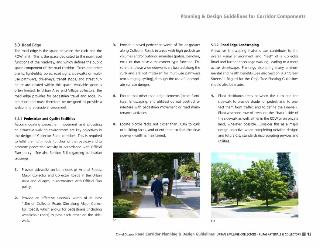
1. Plant deciduous trees between the curb and the
sidewalk to provide shade for pedestrians, to pro-
tect them from traffic, and to define the sidewalk.
Plant a second row of trees on the “back” side of
the sidewalk as well, either in the ROW or on private
land, wherever possible. Consider this as a major
design objective when completing detailed designs
and future City standards incorporating services and
utilities.
5-25-1
Planning & Design Guidelines for Corridor Components
DELCAN Corporation - The Planning Partnership 14
2. When selecting landscape materials (trees, shrubs,
and other vegetation), consider tolerance to salt
spray, sun, shade, wind, and soil conditions, and use
native plant species whenever possible.
3. Use low water demand species, especially in areas
of Ottawa’s problematic marine clay soils that are
prone to differential settlement issues. Follow the
City’s planting guidelines for species selection.
4. Where space permits, locate trees at least 2m to
2.5m from the curb to allow for snow management
and to protect the trees from road salt spray. Offset
them 1.0m from street lights to minimize light inter-
ference.
5. Plant trees no more than 9m apart to provide for a
continuous tree canopy.
6. Provide a permeable surface area of 10m2 minimum
for trees. In highly urban contexts without green
boulevards, provide a continuous planting soil
trench of at least 2m wide and 2m deep.
7. In districts where the desire for enhanced street-
scapes has been identified, choose plantings and
special surface treatments that compliment the
character of surrounding land uses and buildings.
8. Co-ordinate the placement of landscaping features
to minimize conflicts with required servicing and
utility elements.
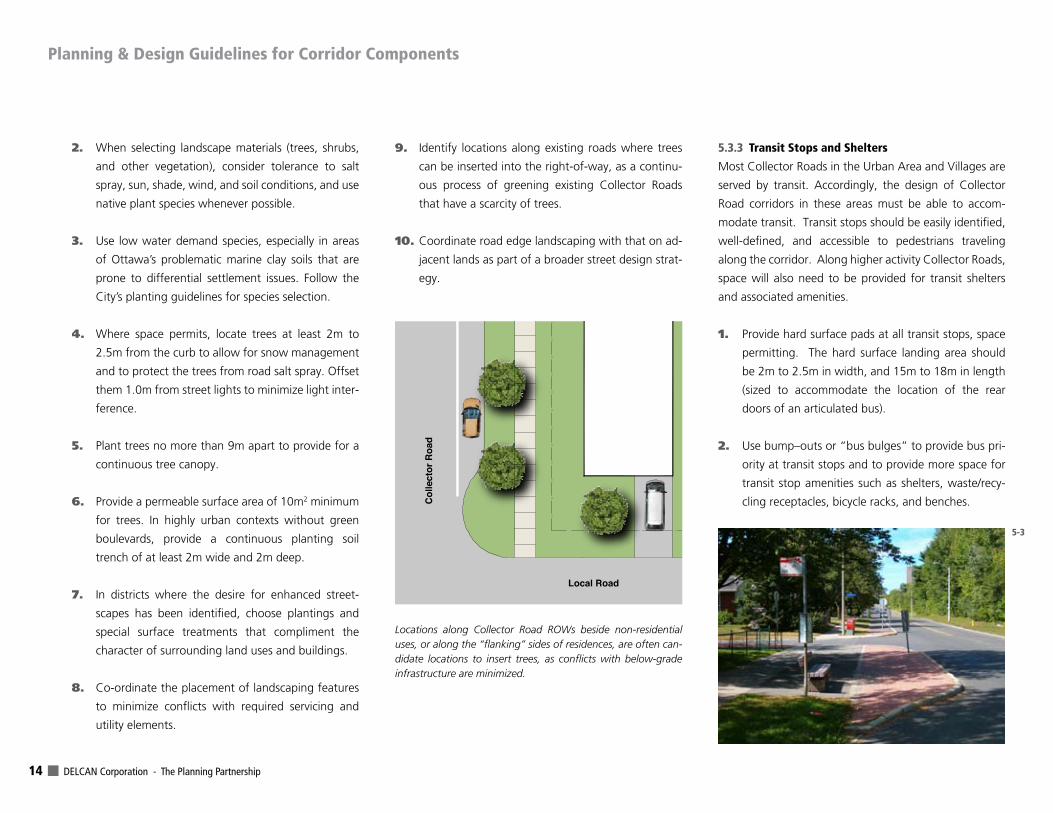
9. Identify locations along existing roads where trees
can be inserted into the right-of-way, as a continu-
ous process of greening existing Collector Roads
that have a scarcity of trees.
10. Coordinate road edge landscaping with that on ad-
jacent lands as part of a broader street design strat-
egy.
5.3.3 Transit Stops and Shelters
Most Collector Roads in the Urban Area and Villages are
served by transit. Accordingly, the design of Collector
Road corridors in these areas must be able to accom-
modate transit. Transit stops should be easily identified,
well-defined, and accessible to pedestrians traveling
along the corridor. Along higher activity Collector Roads,
space will also need to be provided for transit shelters
and associated amenities.
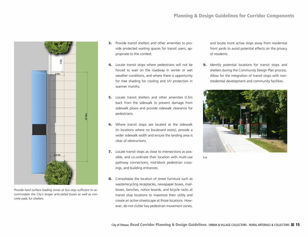
1. Provide hard surface pads at all transit stops, space
permitting. The hard surface landing area should
be 2m to 2.5m in width, and 15m to 18m in length
(sized to accommodate the location of the rear
doors of an articulated bus).
2. Use bump–outs or “bus bulges” to provide bus pri-
ority at transit stops and to provide more space for
transit stop amenities such as shelters, waste/recy-
cling receptacles, bicycle racks, and benches.
Local Road
Col
lect
or R
oad
Locations along Collector Road ROWs beside non-residential uses, or along the “flanking” sides of residences, are often can-didate locations to insert trees, as conflicts with below-grade infrastructure are minimized.
5-3
Planning & Design Guidelines for Corridor Components
City of Ottawa Road Corridor Planning & Design Guidelines URBAN & VILLAGE COLLECTORS - RURAL ARTERIALS & COLLECTORS 15
3. Provide transit shelters and other amenities to pro-
vide protected waiting spaces for transit users, ap-
propriate to the context.
4. Locate transit stops where pedestrians will not be
forced to wait on the roadway in winter or wet
weather conditions, and where there is opportunity
for tree shading for cooling and UV protection in
warmer months.
5. Locate transit shelters and other amenities 0.5m
back from the sidewalk to prevent damage from
sidewalk plows and provide sidewalk clearance for
pedestrians.
6. Where transit stops are located at the sidewalk
(in locations where no boulevard exists), provide a
wider sidewalk width and ensure the landing area is
clear of obstructions.
7. Locate transit stops as close to intersections as pos-
sible, and co-ordinate their location with multi-use
pathway connections, mid-block pedestrian cross-
ings, and building entrances.
8. Consolidate the location of street furniture such as
waste/recycling receptacles, newspaper boxes, mail-
boxes, benches, notice boards, and bicycle racks at
transit stop locations to maximize their utility and
create an active streetscape at those locations. How-
ever, do not clutter key pedestrian movement zones,
and locate more active stops away from residential
front yards to avoid potential effects on the privacy
of residents.
9. Identify potential locations for transit stops and
shelters during the Community Design Plan process.
Allow for the integration of transit stops with non-
residential development and community facilities.
Provide hard surface loading zones at bus stop sufficient to ac-commodate the City’s longer articulated buses as well as con-crete pads for shelters.
5-35-4
Planning & Design Guidelines for Corridor Components
DELCAN Corporation - The Planning Partnership 16
5.4 RoadwayThe roadway is the portion of the public ROW dedicated
to vehicular travel (bicycles, cars, buses, trucks, and emer-
gency vehicles). It may also include a median, and any
space for on-road parking. The roadway design should
accommodate travel by all modes while reinforcing the
role of the street as a public space, and supporting com-
munity activities along the road edge and adjacent lands.
Efforts to calm traffic and to narrow the roadway are
also an increasing City priority in the Urban Area.
5.4.1 Cycling
Collector Roads serve as an important part of the City’s
cycling network, allowing cyclists to travel within and be-
tween neighbourhoods without the need to use higher-
speed and volume Arterial Roads. Accommodation of
cyclists on Collector Roads throughout the Urban Area is
therefore a key concern.
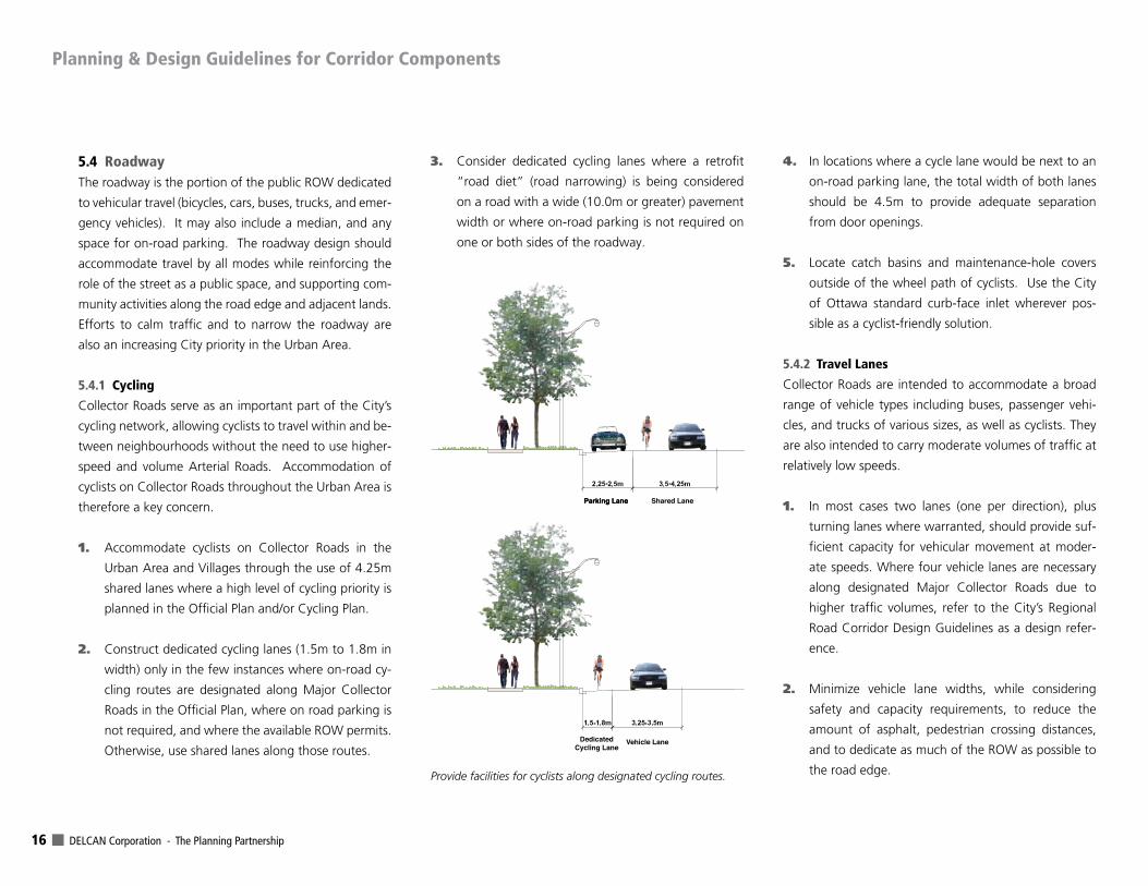
1. Accommodate cyclists on Collector Roads in the
Urban Area and Villages through the use of 4.25m
shared lanes where a high level of cycling priority is
planned in the Official Plan and/or Cycling Plan.
2. Construct dedicated cycling lanes (1.5m to 1.8m in
width) only in the few instances where on-road cy-
cling routes are designated along Major Collector
Roads in the Official Plan, where on road parking is
not required, and where the available ROW permits.
Otherwise, use shared lanes along those routes.
3. Consider dedicated cycling lanes where a retrofit
“road diet” (road narrowing) is being considered
on a road with a wide (10.0m or greater) pavement
width or where on-road parking is not required on
one or both sides of the roadway.
4. In locations where a cycle lane would be next to an
on-road parking lane, the total width of both lanes
should be 4.5m to provide adequate separation
from door openings.
5. Locate catch basins and maintenance-hole covers
outside of the wheel path of cyclists. Use the City
of Ottawa standard curb-face inlet wherever pos-
sible as a cyclist-friendly solution.
5.4.2 Travel Lanes
Collector Roads are intended to accommodate a broad
range of vehicle types including buses, passenger vehi-
cles, and trucks of various sizes, as well as cyclists. They
are also intended to carry moderate volumes of traffic at
relatively low speeds.
1. In most cases two lanes (one per direction), plus
turning lanes where warranted, should provide suf-
ficient capacity for vehicular movement at moder-
ate speeds. Where four vehicle lanes are necessary
along designated Major Collector Roads due to
higher traffic volumes, refer to the City’s Regional
Road Corridor Design Guidelines as a design refer-
ence.
2. Minimize vehicle lane widths, while considering
safety and capacity requirements, to reduce the
amount of asphalt, pedestrian crossing distances,
and to dedicate as much of the ROW as possible to
the road edge.
Parking LaneParking Lane Shared Lane
DedicatedCycling Lane
Vehicle Lane
Provide facilities for cyclists along designated cycling routes.
Planning & Design Guidelines for Corridor Components

City of Ottawa Road Corridor Planning & Design Guidelines URBAN & VILLAGE COLLECTORS - RURAL ARTERIALS & COLLECTORS 17
3. Provide wider lanes in the range of 3.5 to 4.25m for
roads with higher speeds and volumes and mix of
traffic including trucks, buses and larger vehicles as
well as cyclists. For Collectors in Villages and more-
urban contexts, use narrower lanes ranging from
3.0 to 3.5m, with turning lanes at 3.0m.
4. When reconstructing Collector Roads, reduce exist-
ing lane widths to the minimum appropriate widths,
in favour of increasing space for pedestrians, cycling
lanes (where appropriate) and road edge landscap-
ing, to reduce infrastructure life cycle requirements.
5.4.3 On-Road Parking
Given the primary objective for Collector Roads to sup-
port adjacent neighbourhood functions, on-road parking
should generally be provided to meet the needs of resi-
dents, visitors or customers of adjacent land uses. On-
road parking can also provide for traffic calming of Col-
lector Roads if used appropriately. However, provision of
excessive space for on-road parking may result in situa-
tions where more parking is provided than is required.
This leads to unnecessary pavement width, where space
could be better used for road-edge functions such as
landscaping, sidewalks, etc., or where the ROW width
could be reduced.
1. Provide on-road parking on roads with land uses
that are directly accessible from the corridor. This
will calm traffic, separate pedestrians from traffic,
and promote corridor-oriented community activity.
2. Provide bump-outs to define road segments with full
time on-road parking. Bump-outs delineate vehicle
lanes, calm traffic speeds, reduce pedestrian cross-
ing distances, and to provide space for tree plant-
ing, street furniture, transit stops and bicycle park-
ing between the vehicle lanes and the sidewalk.
3. In road retrofits using bump-outs to create a park-
ing lane, use paint striping along the parking lane
to announce and delineate the new use of the road
surface.
4. In areas with lower parking demands, such as along
natural areas or in lower density single detached
housing areas, consider on-road parking on one
side of the street only to reduce pavement width.
Alternate the single parking lane from one side to
the other along the street so that the benefits of
additional landscaping can be shared among both
sides.
5. Plant trees in bump-out areas where appropriate. If
not, construct the sub-grade to the same standard
as under the road pavement to maintain the struc-
tural integrity of the roadway and reduce future
maintenance or re-construction costs. This also al-
lows the bump-out area to be easily converted to
travel lanes or parking if ever appropriate.
6. Construct on-road parking lanes 2.5m wide, with
2.25m acceptable in constrained areas or on lower Use Bump-outs at corners or at the middle of long blocks to define the parking lane and calm traffic.
5-5
Planning & Design Guidelines for Corridor Components
DELCAN Corporation - The Planning Partnership 18
speed/volume roads. Where a parking lane is used
as a travel lane or turn lane during peak hours, it
should be of a lane width appropriate to the street.
7. Limit on-road parking in corridors with dedicated
cycling lanes to reduce conflicts.
5.4.4 Medians
For higher activity Collector Roads with wider ROWs,
there may be the need or desire for placement of a medi-
an between opposing traffic lanes. Medians may also be
used to define a unique urban district or gateway area.
1. Limit the use of medians to reduce the road corridor
width. Use medians as a traffic control measure only
after other measures are considered.
2. Restrict the use of medians to locations at major
intersections along the busiest Collector Roads to
protect left turn lanes, or to control traffic turning
movements at specific locations.
3. Where used at intersections, design the median
with a sufficient width (1.5m) for traffic signal infra-
structure that may be required.
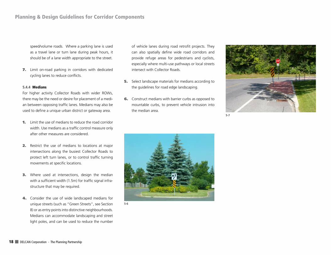
4. Consider the use of wide landscaped medians for
unique streets (such as “Green Streets”, see Section
8) or as entry points into distinctive neighbourhoods.
Medians can accommodate landscaping and street
light poles, and can be used to reduce the number
of vehicle lanes during road retrofit projects. They
can also spatially define wide road corridors and
provide refuge areas for pedestrians and cyclists,
especially where multi-use pathways or local streets
intersect with Collector Roads.
5. Select landscape materials for medians according to
the guidelines for road edge landscaping.
6. Construct medians with barrier curbs as opposed to
mountable curbs, to prevent vehicle intrusion into
the median area.5-7
5-6
Planning & Design Guidelines for Corridor Components
City of Ottawa Road Corridor Planning & Design Guidelines URBAN & VILLAGE COLLECTORS - RURAL ARTERIALS & COLLECTORS 19
5.5 Intersections, Driveways & Turning LanesCollector Roads provide the basic spine of a neighbour-
hood and connect adjacent land uses via a wide array
of intersecting streets, lanes, and driveways. When well-
designed as a system, these elements will lead to a high
degree of community connectivity and a pedestrian/cy-
clist/transit focus that is desired in Ottawa’s neighbour-
hoods.
1. Keep corner curb radii at driveways and intersec-
tions to the minimum possible, to shorten cross-
walk distances and calm turning movements. Use
wider curb radii on corners where Collector Roads
intersect with other collectors and arterials, to ac-
commodate the needs of the range of transit vehi-
cles and trucks using them.
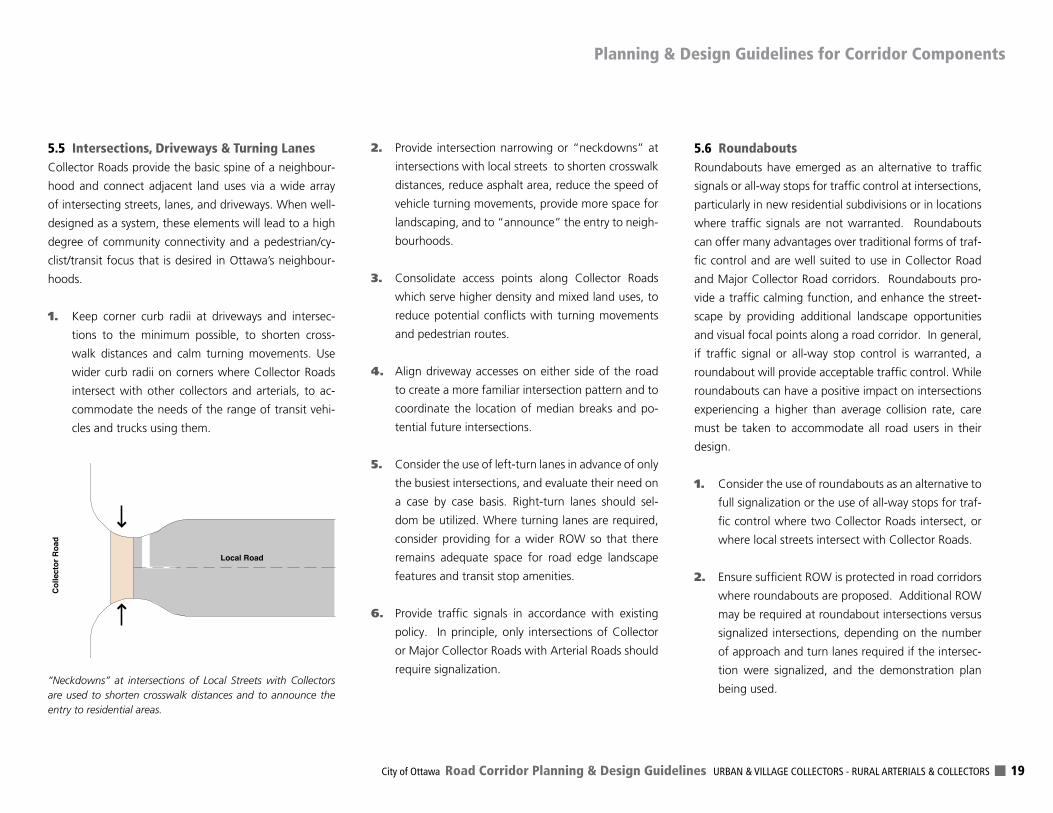
2. Provide intersection narrowing or “neckdowns” at
intersections with local streets to shorten crosswalk
distances, reduce asphalt area, reduce the speed of
vehicle turning movements, provide more space for
landscaping, and to “announce” the entry to neigh-
bourhoods.
3. Consolidate access points along Collector Roads
which serve higher density and mixed land uses, to
reduce potential conflicts with turning movements
and pedestrian routes.
4. Align driveway accesses on either side of the road
to create a more familiar intersection pattern and to
coordinate the location of median breaks and po-
tential future intersections.
5. Consider the use of left-turn lanes in advance of only
the busiest intersections, and evaluate their need on
a case by case basis. Right-turn lanes should sel-
dom be utilized. Where turning lanes are required,
consider providing for a wider ROW so that there
remains adequate space for road edge landscape
features and transit stop amenities.
6. Provide traffic signals in accordance with existing
policy. In principle, only intersections of Collector
or Major Collector Roads with Arterial Roads should
require signalization.
5.6 RoundaboutsRoundabouts have emerged as an alternative to traffic
signals or all-way stops for traffic control at intersections,
particularly in new residential subdivisions or in locations
where traffic signals are not warranted. Roundabouts
can offer many advantages over traditional forms of traf-
fic control and are well suited to use in Collector Road
and Major Collector Road corridors. Roundabouts pro-
vide a traffic calming function, and enhance the street-
scape by providing additional landscape opportunities
and visual focal points along a road corridor. In general,
if traffic signal or all-way stop control is warranted, a
roundabout will provide acceptable traffic control. While
roundabouts can have a positive impact on intersections
experiencing a higher than average collision rate, care
must be taken to accommodate all road users in their
design.
1. Consider the use of roundabouts as an alternative to
full signalization or the use of all-way stops for traf-
fic control where two Collector Roads intersect, or
where local streets intersect with Collector Roads.
2. Ensure sufficient ROW is protected in road corridors
where roundabouts are proposed. Additional ROW
may be required at roundabout intersections versus
signalized intersections, depending on the number
of approach and turn lanes required if the intersec-
tion were signalized, and the demonstration plan
being used.
Local Road
Col
lect
or R
oad
“Neckdowns” at intersections of Local Streets with Collectors are used to shorten crosswalk distances and to announce the entry to residential areas.
Planning & Design Guidelines for Corridor Components
DELCAN Corporation - The Planning Partnership 20
3. Avoid mixing different traffic control treatments
within a road corridor, and avoid placing rounda-
bouts in proximity to a downstream signalized inter-
section to reduce the possibility of queues blocking
the roundabout.
4. Design the roundabout to accommodate a range
of vehicles, with particular attention to transit and
emergency vehicle requirements.
5. In road corridors with designated on-street cycling
lanes, terminate the cycle lane well in advance (25-
30m) of the roundabout entry, to allow cyclists to
merge into the vehicle stream. Bicycle lanes should
not be provided within the roundabout. At loca-
tions with higher bicycle volumes, consider provi-
sion of an off-street multi-use pathway for cyclists.
6. Provide pedestrian crossings at roundabout intersec-
tions at a location 7.5m (one car length) in advance
of the roundabout entry. Use a median island to
allow for a pedestrian refuge.
7. Locate transit stops to avoid potential vehicle queues
extending back into the roundabout.
8. Understand that roundabouts may not be appropri-
ate at locations where transit routes intersect, as the
impact of the roundabout on transit stop location
may result in longer than desirable walking distanc-
es for transit riders transferring between routes.
9. Do not place benches, public art, or other features
in the centre island which may attract pedestrians.
Locate such amenities in a safer location in the road
edge.
10. Give special design consideration when locating
roundabouts in areas with high levels of elderly,
disabled, or visually impaired pedestrian activity.
5.7 Pedestrian CrossingsPedestrian crossings include instances where sidewalks
cross driveways, and where pedestrian routes cross vehi-
cle lanes at crosswalks. These are among the few loca-
tions where pedestrians need to share space with motor-
ized vehicles. The safety and convenience of pedestrians
is of paramount importance.
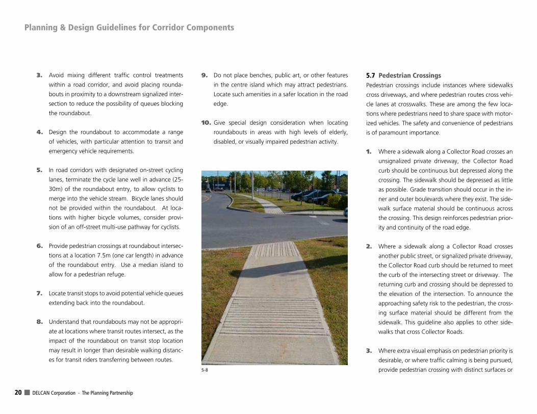
1. Where a sidewalk along a Collector Road crosses an
unsignalized private driveway, the Collector Road
curb should be continuous but depressed along the
crossing. The sidewalk should be depressed as little
as possible. Grade transition should occur in the in-
ner and outer boulevards where they exist. The side-
walk surface material should be continuous across
the crossing. This design reinforces pedestrian prior-
ity and continuity of the road edge.
2. Where a sidewalk along a Collector Road crosses
another public street, or signalized private driveway,
the Collector Road curb should be returned to meet
the curb of the intersecting street or driveway. The
returning curb and crossing should be depressed to
the elevation of the intersection. To announce the
approaching safety risk to the pedestrian, the cross-
ing surface material should be different from the
sidewalk. This guideline also applies to other side-
walks that cross Collector Roads.
3. Where extra visual emphasis on pedestrian priority is
desirable, or where traffic calming is being pursued,
provide pedestrian crossing with distinct surfaces or 5-8
Planning & Design Guidelines for Corridor Components
City of Ottawa Road Corridor Planning & Design Guidelines URBAN & VILLAGE COLLECTORS - RURAL ARTERIALS & COLLECTORS 21
markings. In such instances, the pedestrian cross-
ing may retain a surface elevation that is continuous
with the sidewalk. The crossing surface may differ
from the roadway (or driveway) and the sidewalk
surfaces. The use of such designs may be reviewed
on a case by case basis, taking into account emer-
gency service vehicle needs, pedestrian and vehicle
traffic volumes, and accident history at the cross-
ing.
4. Design sidewalk cross-slopes as well as the slope
and surface transition at depressed curbs or cross-
ings to be as gentle and barrier-free as possible.
5. Include safeguards such as detectable warning sur-
faces, directional textures, warning signs, audible
signals, paint markings, and clear sight lines, where
sidewalks or multi-use pathways cross intersections
or driveways, so that cyclists and pedestrians of all
ability are made aware of approaching crosswalks
and their routes.
6. Orient the direction of curb ramps and their surface
treatments at pedestrian crossings in the same direc-
tion as the crossing, so that visually impaired people
are directed correctly, as well as providing a tactile
warning sidewalk surface (perpendicular grooves) in
advance of the ramp.
7. Avoid locating individual formal pedestrian crossings
at mid-block locations. Where they are absolutely
necessary, provide traffic signals in accordance with
City warrants. Pedestrian routes should be designed
so that crossings are consolidated at traffic intersec-
tions.
8. Reduce pavement width through the use of bump-
outs at pedestrian crossing locations to reduce
crossing distances and to provide greater visibility at
crossing points.
9. Use textured pavement, coloured pavement, or oth-
er treatments to delineate high priority pedestrian
crossings such as near schools or crossings of multi-
use pathways.
5.8 Linear Services, Utilities & Road OperationsOne of the fundamental functions of Collector Roads in
the Urban Area is to provide a corridor for many vital
City services and utilities. These include water, wastewa-
ter, and stormwater services as well as utilities including
electric, gas, and telecommunications. Postal service also
needs to be accommodated. Collector Road corridors
must be well-illuminated, well-drained, and as cost ef-
fective as possible to construct and maintain over their
life-cycle.
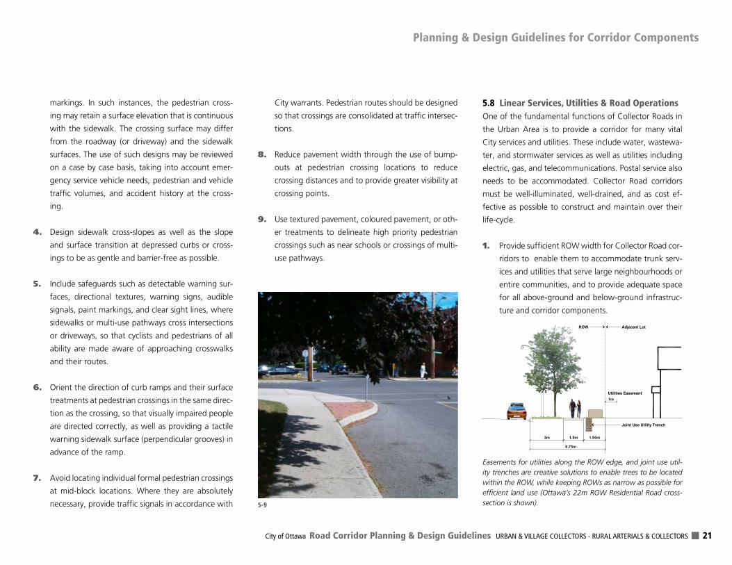
1. Provide sufficient ROW width for Collector Road cor-
ridors to enable them to accommodate trunk serv-
ices and utilities that serve large neighbourhoods or
entire communities, and to provide adequate space
for all above-ground and below-ground infrastruc-
ture and corridor components.
Adjacent Lot
Utilities Easement
Joint Use Utility Trench
ROW
Easements for utilities along the ROW edge, and joint use util-ity trenches are creative solutions to enable trees to be located within the ROW, while keeping ROWs as narrow as possible for efficient land use (Ottawa’s 22m ROW Residential Road cross-section is shown).5-9
Planning & Design Guidelines for Corridor Components
DELCAN Corporation - The Planning Partnership 22
2. Provide adequate space and separations for the lo-
cation, access and maintenance of services and utili-
ties. Use shared use trenches (as per City of Ottawa
Utility Coordinating Committee Guidelines), shared
use poles, and other creative measures to balance
the use of space for all corridor components and to
minimize ROW widths.
3. Where there is a municipal objective to minimize the
width of ROWs, use easements on adjacent land to
provide for the location, operation and maintenance
of utilities. Obtain these easements at no cost to the
City or the utilities.
4. Bury utilities in new Collector Roads in the Urban
Area, with the exception of: industrially-zoned ar-
eas, instances where it is appropriate for electrical
trunk overhead lines to follow a Collector Road cor-
ridor, and locations where consistency with over-
head service is required.
5. For new road construction, assign the costs associ-
ated with the burying of utilities to the developer.
At no cost to the utility or the City, the developer
will provide any requested easements to provide for
the location of or access to services, ducts, chamber
cables or padmounted equipment, as well as provid-
ing vaults located within buildings where required.
6. When preparing Community Design Plans for Tra-
ditional Mainstreets, Mixed Use Centres, and other
areas where reduced ROW widths are proposed and
utilities are to be buried, include provisions that in-
form developers and other stakeholders of the im-
plications associated with burying and that utility
easements and utility equipment may need to be
provided outside of the ROW and/or in buildings at
no cost to the City or utilities.
7. Where electrical service is to be buried in narrow
road corridors with narrow road edges, including
designs with sidewalks located along or near the
ROW limit, provide appropriate space in the road
edges for ducts (contiguously under the sidewalk)
and cable chambers, as well as padmounted equip-
ment and switches as required. Easements for the
location of or access to infrastructure on adjacent
land may be required. Shared vault space in build-
ings may also be required.
8. Where electrical service is to be buried in road cor-
ridors with wider road edges, including designs that
have a grassy boulevard between the sidewalk and
ROW limit, provide boulevards that are wide enough
(2.0m minimum) to accommodate pad-mounted
equipment and switches. Do so to minimize the
width of easement that may be required on adja-
cent land and to minimize the need to protect the
transformer or switch with bollards.
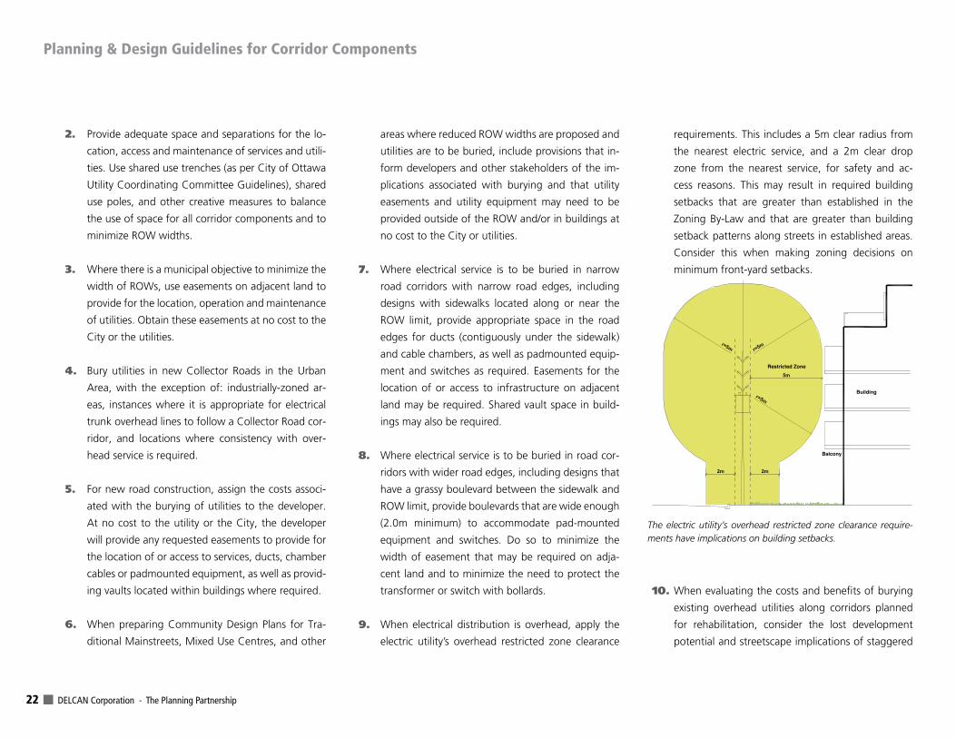
9. When electrical distribution is overhead, apply the
electric utility’s overhead restricted zone clearance
requirements. This includes a 5m clear radius from
the nearest electric service, and a 2m clear drop
zone from the nearest service, for safety and ac-
cess reasons. This may result in required building
setbacks that are greater than established in the
Zoning By-Law and that are greater than building
setback patterns along streets in established areas.
Consider this when making zoning decisions on
minimum front-yard setbacks.
10. When evaluating the costs and benefits of burying
existing overhead utilities along corridors planned
for rehabilitation, consider the lost development
potential and streetscape implications of staggered
Building
Balcony
Restricted Zone
The electric utility’s overhead restricted zone clearance require-ments have implications on building setbacks.
Planning & Design Guidelines for Corridor Components
City of Ottawa Road Corridor Planning & Design Guidelines URBAN & VILLAGE COLLECTORS - RURAL ARTERIALS & COLLECTORS 23
building setbacks that may result from the applica-
tion of the electric utility’s overhead restricted zone
clearance requirements.
11. Where utilities are located near the ROW limit or on
adjacent lands under easement, require buildings to
be set back from the ROW limit an appropriate dis-
tance to provide for the operation and maintenance
of utilities. For example, additional separation is re-
quired when gas service is located on adjacent lands
in the area between pad-mount transformers and
buildings/structures (such as in four-party shared
use trench arrangements), to enable access to the
utility.
12. Where reduced building setbacks are proposed, en-
sure that adequate clearance for utility assets, for
protective devices (such as bollards if needed), and
for work on the assets is retained. This is to avoid,
for example, the need for permanent blast protec-
tion walls around surface mounted electrical equip-
ment, the dangerous and costly collapse of utility
trenches for building encroachments, or the costly
excavation work by hand near utilities.
13. Locate surface-mounted utility equipment (trans-
former pads, telecommunication pedestals, etc.)
away from driveways, intersections, sight triangles,
or key view lines, in accordance with the City’s
Guidelines for Utility Pedestals Within the Road
Right-of-Way (2003) and Utility Coordination Com-
mittee Guidelines.
14. Where surface-mounted utility equipment needs to
be located on adjacent lands (subject to easements),
locate it to the side or rear of buildings, at corners of
parking lots, and buffer its visual impacts with land-
scaping that is well-integrated with the site while
providing access to the infrastructure.
15. Follow the electric utility’s “Tree Planting Advice”
when planting near distribution assets, including the
requirement that trees under overhead lines need to
be species that grow to less then 6m in height at
maturity.
16. Consider trees in the road corridor as an important
public asset and coordinate service and utility de-
signs to provide space for trees so that their benefits
can be maximized and conflicts with services and
utilities are minimized.
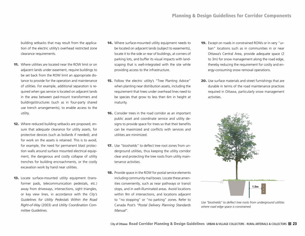
17. Use “bioshields” to deflect tree root zones from un-
derground utilities, thus keeping the utility corridor
clear and protecting the tree roots from utility main-
tenance activities.
18. Provide space in the ROW for postal service elements
including community mail boxes. Locate these amen-
ities conveniently, such as near pathways or transit
stops, and in well-illuminated areas. Avoid locations
within 9m of intersections, and locations adjacent
to “no stopping” or “no parking” zones. Refer to
Canada Post’s “Postal Delivery Planning Standards
Manual”.
19. Except on roads in constrained ROWs or in very “ur-
ban” locations such as in communities in or near
Ottawa’s Central Area, provide adequate space (2
to 3m) for snow management along the road edge,
thereby reducing the requirement for costly and en-
ergy-consuming snow removal operations.
20. Use surface materials and street furnishings that are
durable in terms of the road maintenance practices
required in Ottawa, particularly snow management
activities.
Use “bioshields” to deflect tree roots from underground utilities where road edge space is constrained.
Planning & Design Guidelines for Corridor Components
DELCAN Corporation - The Planning Partnership 24
21. Design road sub-grades to carry higher vehicle vol-
umes and heavier vehicles such as buses that may
be using the corridors regularly.
22. Design roadway lighting to correspond to the road’s
land use context. Specific pedestrian-scale light-
ing should be considered on collectors in priority
mixed-use or mainstreet environments. Reference
should be made to the ROW Lighting Policy (2007)
for specific policies and standards when completing
designs.
23. Use joint-service (street light and utilities) poles to
reduce the number of poles in the corridor when
utilities are overhead.
24. Consider the use of innovative or emerging best
practices for sustainable and “green” infrastructure,
including those presented in Section 4.2.
5.9 RetrofittingMeasuresandRoadDietsSuccessful new neighbourhoods are designed with the
objective of achieving an efficient and balanced trans-
portation system, with traffic management measures
built into the design. For the retrofit of existing corridors
experiencing traffic concerns, traffic management ap-
proaches will differ depending on the nature and func-
tion of the road in question. A “road diet” or narrowing
is a traffic management technique used to reduce the
number of vehicle travel lanes, primarily those with traf-
fic safety issues (speeding, collisions) which may be the
result of excessive vehicle capacity.
1. Design new Collector Road corridors to be efficiently
and safely used and to prevent the need for retrofit-
ting with traffic management or road diet measures
after build-out.
2. Use bump-outs along reconstructed Collector Roads
that have on-road parking, to better define the trav-
el lanes, to create road edge friction, and to create
protected parking bays.
3. Avoid constructing new Collector Roads in suburban
settings that have design elements more reflective
of Arterial Road design (such as four traffic lanes) as
this may set the stage for future conflicts between
the intended function of the roadway and its opera-
tional reality (such as high speeds).
4. Assess the potential of any proposed traffic man-
agement measures to negatively impact the multi-
modal and goods movement function of a Collector
Road, before implementation.
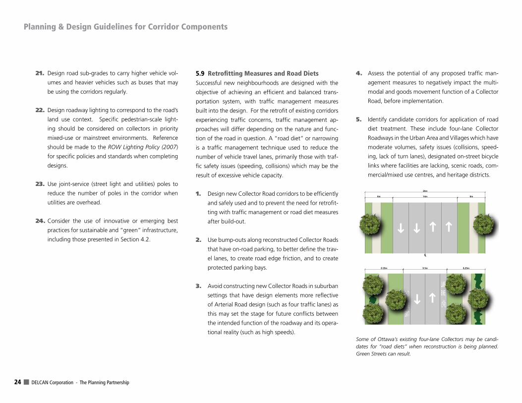
5. Identify candidate corridors for application of road
diet treatment. These include four-lane Collector
Roadways in the Urban Area and Villages which have
moderate volumes, safety issues (collisions, speed-
ing, lack of turn lanes), designated on-street bicycle
links where facilities are lacking, scenic roads, com-
mercial/mixed use centres, and heritage districts.
CL
Some of Ottawa’s existing four-lane Collectors may be candi-dates for “road diets” when reconstruction is being planned. Green Streets can result.
Planning & Design Guidelines for Corridor Components
City of Ottawa Road Corridor Planning & Design Guidelines URBAN & VILLAGE COLLECTORS - RURAL ARTERIALS & COLLECTORS 25
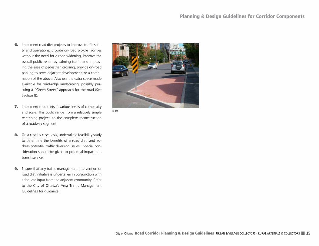
6. Implement road diet projects to improve traffic safe-
ty and operations, provide on-road bicycle facilities
without the need for a road widening, improve the
overall public realm by calming traffic and improv-
ing the ease of pedestrian crossing, provide on-road
parking to serve adjacent development, or a combi-
nation of the above. Also use the extra space made
available for road-edge landscaping, possibly pur-
suing a “Green Street” approach for the road (See
Section 8).
7. Implement road diets in various levels of complexity
and scale. This could range from a relatively simple
re-striping project, to the complete reconstruction
of a roadway segment.
8. On a case by case basis, undertake a feasibility study
to determine the benefits of a road diet, and ad-
dress potential traffic diversion issues. Special con-
sideration should be given to potential impacts on
transit service.
9. Ensure that any traffic management intervention or
road diet initiative is undertaken in conjunction with
adequate input from the adjacent community. Refer
to the City of Ottawa’s Area Traffic Management
Guidelines for guidance.
5-10
Planning & Design Guidelines for Corridor Components
DELCAN Corporation - The Planning Partnership 26
The design of the City’s Collector and Arterial Roads in
the Rural Area should respond to the unique land use
context and rural drainage systems (roadside ditches) that
differentiate their cross-sections. Whereas the design of
urban roads is more influenced by adjacent land uses,
buildings, pedestrian activity, and public space functions,
the design focus on roads located in the Rural Area is on
integration with the landscape and natural processes.
1. Minimize the displacement of rural lands by keeping
the required ROW as narrow as possible, working
within designated ROW widths wherever feasible.
Achieve this efficiency by reducing the number of
lanes and reducing lane widths wherever feasible,
avoiding wide medians where safe to do so, while
maintaining safe road cross-sections and appropri-
ate roadside drainage.
2. For roads that travel along the boundary of the des-
ignated Urban Area and the Rural Area, provide an
urban cross-section on the designated Urban side of
the road and provide a rural cross-section along the
Rural side. Protect ROWs accordingly for those seg-
ments.
3. Use open grassy swales and ditches (rather than road
edge curbs, catch basins and storm water pipes) or
other creative options for roadside drainage in the
Rural Area, to better reflect the rural setting, ac-
cept adjacent farmland drainage, control the rate of
discharge, encourage groundwater infiltration, and
manage surface water quality. Where the drainage
swale may become too deep and/or wide to resolve
grades, consider a combination of grassy swale and
perforated pipe system under the swale. Use these
solutions for Village collectors that are intended to
have a rural type (non-curb) cross-section and where
sidewalks need to fit within the available ROW.
4. Along roadside ditches, use gentle side slopes, pref-
erably 4:1 and not steeper than 3:1, to accommo-
date grass, plantings, and maintenance activities and
to address road safety (vehicle recovery and roll-over
avoidance). Where steeper ditch slopes are required
in constrained areas, plant low maintenance vegeta-
tion.
5. Consider paving a portion (0.5m up to 1.5m) of road
shoulders when rehabilitating, resurfacing, or con-
structing new rural arterials and collectors. Do this
to improve traffic safety by providing additional re-
covery area, minimizing roll-over risk, and reducing
risk of collision with fixed objects, particularly along
higher speed roads. Take advantage of the added
value for farm vehicle movement and cycling, walk-
ing, jogging, running along the road edge. Decisions
regarding shoulder paving should be made on a case
by case basis while having regard to the road desig-
nation in the Official Plan and the Cycling Plan and
Pedestrian Plan, the cost to implement, as well as fu-
ture Road Design Guidelines that may provide further
guidance including potential life cycle cost benefits.
6. Where paved shoulders are to be provided, con-
struct “rumble strips” on a pilot project basis to
test their road safety advantages and operational
requirements, and to evaluate their impact on cy-
clists. Where paved shoulders are used by cyclists,
the width of the rumble strip and a 0.3m clear
zone should be in addition to the desired shoulder
width.
7. Provide safe passenger waiting areas at bus stop
locations along rural roads by widening the road
shoulder, or ideally, by providing hard surface pads
that could accommodate a bus shelter.
8. Provide culverts and lanes to permit farm vehicles
to cross the roadway and to access adjacent lands
where required, and involve landowners in the
choice of location when constructing new roads.
9. To reduce the required ROW and maintain a rural
character, avoid the use of raised curb medians un-
less needed for road safety. As an alternative, con-
sider the use of grooved rumble strips, separated
paint lines, turf swales, and other creative designs
that have the affect of separating opposing traffic
lanes. When evaluating the need for separation,
consider traffic speeds, traffic volumes, traffic mix,
number of lanes, left-turn lane locations, and ad-
jacent land uses. At the rural/urban interface, and
when there is no reasonable solution to providing
raised curb medians, consider the need for piped
Rural Conditions
6.0
City of Ottawa Road Corridor Planning & Design Guidelines URBAN & VILLAGE COLLECTORS - RURAL ARTERIALS & COLLECTORS 27
drainage systems (curb and catch basins) along
them.
10. Where identified in approved plans or studies, lo-
cate multi-use pathways in the ROW. Secure a wider
ROW and locate the pathway near the ROW limit,
separated from the vehicle lanes. Where the road-
way forms a boundary between the Rural Area and
an Urban Area, consider substituting a City sidewalk
with a multi-use pathway along the urban side of
the ROW, to consolidate pedestrian/cycling surfaces
and to enhance the user experience.
11. Illuminate roads only where needed for road user
safety, to retain the Rural Area’s dark night sky.
When evaluating the need, consider: the number of
vehicle lanes, traffic volumes, intersection locations,
cycling route function, location/proximity of pedes-
trian crossings or routes, road segment length, and
road corridor lighting continuity. Where roadside
lighting is required, design systems that reduce the
overall ambient glow on the rural landscape, includ-
ing the use of full cut-off luminaires. Refer to the
City’s Right-of-Way lighting Policy (2007)
12. Where roadside planting is appropriate in the ROW,
design it to complement the variable rural charac-
ter adjacent to the corridor (agricultural fields ver-
sus rural residential, etc.). Use species commonly
or historically found in the region and plant in rural
and naturalized patterns including groupings and
uneven spacings. Where roadside planting cannot
be accommodated in the ROW, consider locating
it outside of the ROW on adjacent lands to reduce
the required ROW, to provide an unencumbered
growing area, and to reduce potential conflicts with
above-grade or below-grade services.
13. Consolidate utilities and services (buried and over-
head) along the ROW limit, on shared-use poles,
and along one side of the road whenever possible.
This will reduce the visual impact on the Rural Area,
provide more unencumbered space for planting,
drainage, and will improve road safety.
14. Overhead utility pole lines are typically located at
the ROW edge, close to the property line. However,
where the pole line would be located in a ditch or
where the pole would be shared with street lighting,
the pole line may be placed closer to the traveled
road edge.
15. Locate trees so that they are a minimum of 3m when
mature from any overhead lines, to allow canopy
growth with minimal pruning. Consider locating
light fixtures on utility poles, to minimize poles and
provide fewer conflicts with potential tree planting
as well as improving road safety.
16. Avoid impacts on valued natural and cultural heritage
features (including federally significant resources)
when designing and constructing new rural roads. If
such features must be displaced or diminished due
to construction activities, they should be replaced or
enhanced with features of equal or greater value,
either in the ROW or on adjacent lands.
17. For road segments prone to snow drifting such as
along open windswept areas, provide opportunities
on adjacent rural lands along the windward side of
the road for snow drift management. Use measures
such as retaining corn crops, planting hedgerows, or
using snow fencing in the most problematic areas.
Review the City’s Alternative Snow Fence Program
for further guidance.
18. Coordinate the erection of the City’s tourism way-
finding signs and visitor attraction signs with other
regulatory, tourism, and public service signs, and
cycle route signs.
19. Protect wider ROWs in the vicinity of creek and drain
crossings, to provide extra space for culvert location
and maintenance. Include provisions in the Official
Plan to take triangular road widenings as a condi-
tion of development approvals.
Rural Conditions
Prevailing Winds
Snow Drift
6-12 Rowsof Corn
Improve winter motorist safety by compensating farmers to leave unharvested corn as snow-breaks along problematic windswept road segments.
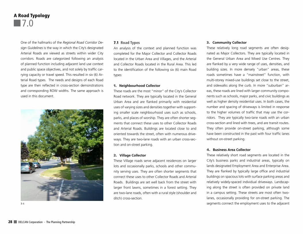
DELCAN Corporation - The Planning Partnership 28
One of the hallmarks of the Regional Road Corridor De-
sign Guidelines is the way in which the City’s designated
Arterial Roads are viewed as streets within wider City
corridors. Roads are categorized following an analysis
of planned function including adjacent land use context
and public space objectives, and not solely by traffic car-
rying capacity or travel speed. This resulted in six (6) Ar-
terial Road types. The needs and designs of each Road
type are then reflected in cross-section demonstrations
and corresponding ROW widths. The same approach is
used in this document.
7.1 Road TypesAn analysis of the context and planned function was
completed for the Major Collector and Collector Roads
located in the Urban Area and Villages, and the Arterial
and Collector Roads located in the Rural Area. This led
to the identification of the following six (6) main Road
types:
1. Neighbourhood Collector
These roads are the most “minor” of the City’s Collector
Road network. They are typically located in the General
Urban Area and are flanked primarily with residential
uses of varying sizes and densities together with support-
ing smaller scale neighbourhood uses such as schools,
parks, and places of worship. They are often shorter seg-
ments that connect these uses to other Collector Roads
and Arterial Roads. Buildings are located close to and
oriented towards the street, often with numerous drive-
ways. They are two-lane roads with an urban cross-sec-
tion and on-street parking.
2. Village Collector
These Village roads serve adjacent residences on larger
lots and occasionally parks, schools and other commu-
nity serving uses. They are often shorter segments that
connect these uses to other Collector Roads and Arterial
Roads. Buildings are set well back from the street with
larger front lawns, sometimes in a forest setting. They
are two-lane roads, often with a rural style (shoulder and
ditch) cross-section.
3. Community Collector
These relatively long road segments are often desig-
nated as Major Collectors. They are typically located in
the General Urban Area and Mixed Use Centres. They
are flanked by a very wide range of uses, densities, and
building sizes. In more densely “urban” areas, these
roads sometimes have a “mainstreet” function, with
multi-storey mixed-use buildings set close to the street,
and sidewalks along the curb. In more “suburban” ar-
eas, these roads are lined with larger community compo-
nents such as schools, major parks, and civic buildings as
well as higher density residential uses. In both cases, the
number and spacing of driveways is limited in response
to the higher volumes of traffic that may use the cor-
ridors. They are typically two-lane roads with an urban
cross-section and lined with trees, and are transit routes.
They often provide on-street parking, although some
have been constructed in the past with four traffic lanes
without on-street parking.
4. Business Area Collector
These relatively short road segments are located in the
City’s business parks and industrial areas, typically on
lands designated Employment Area and Enterprise Area.
They are flanked by typically large office and industrial
buildings on spacious lots with surface parking areas and
relatively widely-spaced individual driveways. Landscap-
ing along the street is often provided on private land
in a campus setting. These streets are most often two-
lanes, occasionally providing for on-street parking. The
segments connect the employment uses to the adjacent 7-1
A Road Typology
7.0
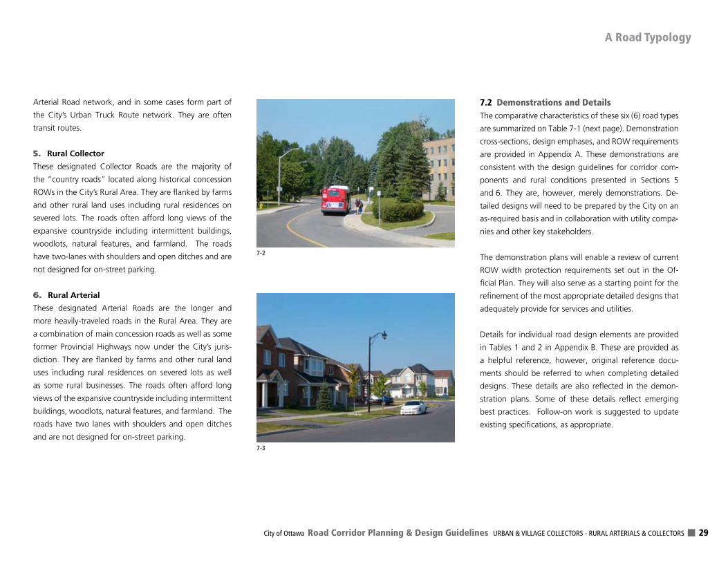
City of Ottawa Road Corridor Planning & Design Guidelines URBAN & VILLAGE COLLECTORS - RURAL ARTERIALS & COLLECTORS 29
Arterial Road network, and in some cases form part of
the City’s Urban Truck Route network. They are often
transit routes.
5. Rural Collector
These designated Collector Roads are the majority of
the “country roads” located along historical concession
ROWs in the City’s Rural Area. They are flanked by farms
and other rural land uses including rural residences on
severed lots. The roads often afford long views of the
expansive countryside including intermittent buildings,
woodlots, natural features, and farmland. The roads
have two-lanes with shoulders and open ditches and are
not designed for on-street parking.
6. Rural Arterial
These designated Arterial Roads are the longer and
more heavily-traveled roads in the Rural Area. They are
a combination of main concession roads as well as some
former Provincial Highways now under the City’s juris-
diction. They are flanked by farms and other rural land
uses including rural residences on severed lots as well
as some rural businesses. The roads often afford long
views of the expansive countryside including intermittent
buildings, woodlots, natural features, and farmland. The
roads have two lanes with shoulders and open ditches
and are not designed for on-street parking.
7.2 Demonstrations and DetailsThe comparative characteristics of these six (6) road types
are summarized on Table 7-1 (next page). Demonstration
cross-sections, design emphases, and ROW requirements
are provided in Appendix A. These demonstrations are
consistent with the design guidelines for corridor com-
ponents and rural conditions presented in Sections 5
and 6. They are, however, merely demonstrations. De-
tailed designs will need to be prepared by the City on an
as-required basis and in collaboration with utility compa-
nies and other key stakeholders.
The demonstration plans will enable a review of current
ROW width protection requirements set out in the Of-
ficial Plan. They will also serve as a starting point for the
refinement of the most appropriate detailed designs that
adequately provide for services and utilities.
Details for individual road design elements are provided
in Tables 1 and 2 in Appendix B. These are provided as
a helpful reference, however, original reference docu-
ments should be referred to when completing detailed
designs. These details are also reflected in the demon-
stration plans. Some of these details reflect emerging
best practices. Follow-on work is suggested to update
existing specifications, as appropriate.
A Road Typology
7-3
7-2
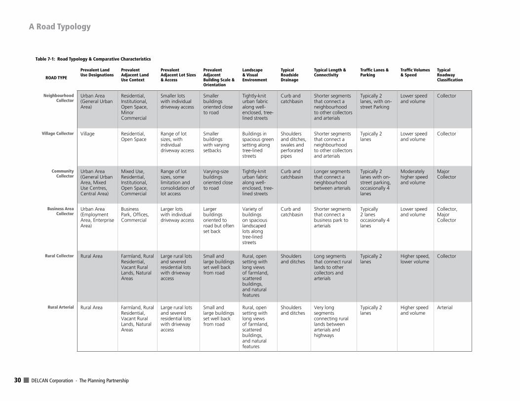
DELCAN Corporation - The Planning Partnership 30
A Road Typology
ROAD TYPE
Prevalent Land Use Designations
Prevalent Adjacent Land Use Context
Prevalent Adjacent Lot Sizes & Access
Prevalent Adjacent Building Scale & Orientation
Landscape & Visual Environment
Typical Roadside Drainage
Typical Length & Connectivity
Traffic Lanes & Parking
Traffic Volumes & Speed
Typical Roadway Classification
Neighbourhood Collector
Urban Area (General Urban Area)
Residential, Institutional, Open Space, Minor Commercial
Smaller lots with individual driveway access
Smaller buildings oriented close to road
Tightly-knit urban fabric along well-enclosed, tree-lined streets
Curb and catchbasin
Shorter segments that connect a neighbourhood to other collectors and arterials
Typically 2 lanes, with on-street Parking
Lower speed and volume
Collector
Village Collector Village Residential, Open Space
Range of lot sizes, with individual driveway access
Smaller buildings with varying setbacks
Buildings in spacious green setting along tree-lined streets
Shoulders and ditches, swales and perforated pipes
Shorter segments that connect a neighbourhood to other collectors and arterials
Typically 2 lanes
Lower speed and volume
Collector
Community Collector
Urban Area (General Urban Area, Mixed Use Centres, Central Area)
Mixed Use, Residential, Institutional, Open Space, Commercial
Range of lot sizes, some limitation and consolidation of lot access
Varying-size buildings oriented close to road
Tightly-knit urban fabric along well-enclosed, tree-lined streets
Curb and catchbasin
Longer segments that connect a neighbourhood between arterials
Typically 2 lanes with on-street parking, occasionally 4 lanes
Moderately higher speed and volume
Major Collector
Business Area Collector
Urban Area (Employment Area, Enterprise Area)
Business Park, Offices, Commercial
Larger lots with individual driveway access
Larger buildings oriented to road but often set back
Variety of buildings on spacious landscaped lots along tree-lined streets
Curb and catchbasin
Shorter segments that connect a business park to arterials
Typically 2 lanes occasionally 4 lanes
Lower speed and volume
Collector, Major Collector
Rural Collector Rural Area Farmland, Rural Residential, Vacant Rural Lands, Natural Areas
Large rural lots and severed residential lots with driveway access
Small and large buildings set well back from road
Rural, open setting with long views of farmland, scattered buildings, and natural features
Shoulders and ditches
Long segments that connect rural lands to other collectors and arterials
Typically 2 lanes
Higher speed, lower volume
Collector
Rural Arterial Rural Area Farmland, Rural Residential, Vacant Rural Lands, Natural Areas
Large rural lots and severed residential lots with driveway access
Small and large buildings set well back from road
Rural, open setting with long views of farmland, scattered buildings, and natural features
Shoulders and ditches
Very long segments connecting rural lands between arterials and highways
Typically 2 lanes
Higher speed and volume
Arterial
Table 7-1: Road Typology & Comparative Characteristics
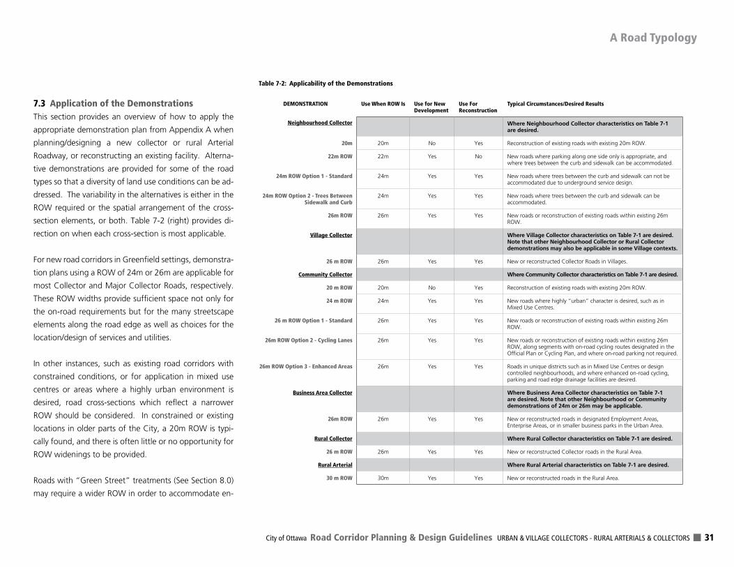
City of Ottawa Road Corridor Planning & Design Guidelines URBAN & VILLAGE COLLECTORS - RURAL ARTERIALS & COLLECTORS 31
7.3 Application of the DemonstrationsThis section provides an overview of how to apply the
appropriate demonstration plan from Appendix A when
planning/designing a new collector or rural Arterial
Roadway, or reconstructing an existing facility. Alterna-
tive demonstrations are provided for some of the road
types so that a diversity of land use conditions can be ad-
dressed. The variability in the alternatives is either in the
ROW required or the spatial arrangement of the cross-
section elements, or both. Table 7-2 (right) provides di-
rection on when each cross-section is most applicable.
For new road corridors in Greenfield settings, demonstra-
tion plans using a ROW of 24m or 26m are applicable for
most Collector and Major Collector Roads, respectively.
These ROW widths provide sufficient space not only for
the on-road requirements but for the many streetscape
elements along the road edge as well as choices for the
location/design of services and utilities.
In other instances, such as existing road corridors with
constrained conditions, or for application in mixed use
centres or areas where a highly urban environment is
desired, road cross-sections which reflect a narrower
ROW should be considered. In constrained or existing
locations in older parts of the City, a 20m ROW is typi-
cally found, and there is often little or no opportunity for
ROW widenings to be provided.
Roads with “Green Street” treatments (See Section 8.0)
may require a wider ROW in order to accommodate en-
A Road Typology
DEMONSTRATION Use When ROW Is Use for New Development
Use For Reconstruction
Typical Circumstances/Desired Results
Neighbourhood Collector Where Neighbourhood Collector characteristics on Table 7-1 are desired.
20m 20m No Yes Reconstruction of existing roads with existing 20m ROW.
22m ROW 22m Yes No New roads where parking along one side only is appropriate, and where trees between the curb and sidewalk can be accommodated.
24m ROW Option 1 - Standard 24m Yes Yes New roads where trees between the curb and sidewalk can not be accommodated due to underground service design.
24m ROW Option 2 - Trees Between Sidewalk and Curb
24m Yes Yes New roads where trees between the curb and sidewalk can be accommodated.
26m ROW 26m Yes Yes New roads or reconstruction of existing roads within existing 26m ROW.
Village Collector Where Village Collector characteristics on Table 7-1 are desired. Note that other Neighbourhood Collector or Rural Collector demonstrations may also be applicable in some Village contexts.
26 m ROW 26m Yes Yes New or reconstructed Collector Roads in Villages.
Community Collector Where Community Collector characteristics on Table 7-1 are desired.
20 m ROW 20m No Yes Reconstruction of existing roads with existing 20m ROW.
24 m ROW 24m Yes Yes New roads where highly “urban” character is desired, such as in Mixed Use Centres.
26 m ROW Option 1 - Standard 26m Yes Yes New roads or reconstruction of existing roads within existing 26m ROW.
26m ROW Option 2 - Cycling Lanes 26m Yes Yes New roads or reconstruction of existing roads within existing 26m ROW, along segments with on-road cycling routes designated in the Official Plan or Cycling Plan, and where on-road parking not required.
26m ROW Option 3 - Enhanced Areas 26m Yes Yes Roads in unique districts such as in Mixed Use Centres or design controlled neighbourhoods, and where enhanced on-road cycling, parking and road edge drainage facilities are desired.
Business Area Collector Where Business Area Collector characteristics on Table 7-1 are desired. Note that other Neighbourhood or Community demonstrations of 24m or 26m may be applicable.
26m ROW 26m Yes Yes New or reconstructed roads in designated Employment Areas, Enterprise Areas, or in smaller business parks in the Urban Area.
Rural Collector Where Rural Collector characteristics on Table 7-1 are desired.
26 m ROW 26m Yes Yes New or reconstructed Collector roads in the Rural Area.
Rural Arterial Where Rural Arterial characteristics on Table 7-1 are desired.
30 m ROW 30m Yes Yes New or reconstructed roads in the Rural Area.
Table 7-2: Applicability of the Demonstrations
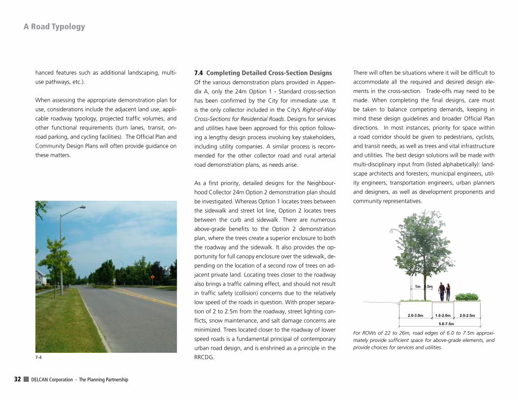
DELCAN Corporation - The Planning Partnership 32
hanced features such as additional landscaping, multi-
use pathways, etc.).
When assessing the appropriate demonstration plan for
use, considerations include the adjacent land use, appli-
cable roadway typology, projected traffic volumes, and
other functional requirements (turn lanes, transit, on-
road parking, and cycling facilities). The Official Plan and
Community Design Plans will often provide guidance on
these matters.
7.4 Completing Detailed Cross-Section Designs Of the various demonstration plans provided in Appen-
dix A, only the 24m Option 1 - Standard cross-section
has been confirmed by the City for immediate use. It
is the only collector included in the City’s Right-of-Way
Cross-Sections for Residential Roads. Designs for services
and utilities have been approved for this option follow-
ing a lengthy design process involving key stakeholders,
including utility companies. A similar process is recom-
mended for the other collector road and rural arterial
road demonstration plans, as needs arise.
As a first priority, detailed designs for the Neighbour-
hood Collector 24m Option 2 demonstration plan should
be investigated. Whereas Option 1 locates trees between
the sidewalk and street lot line, Option 2 locates trees
between the curb and sidewalk. There are numerous
above-grade benefits to the Option 2 demonstration
plan, where the trees create a superior enclosure to both
the roadway and the sidewalk. It also provides the op-
portunity for full canopy enclosure over the sidewalk, de-
pending on the location of a second row of trees on ad-
jacent private land. Locating trees closer to the roadway
also brings a traffic calming effect, and should not result
in traffic safety (collision) concerns due to the relatively
low speed of the roads in question. With proper separa-
tion of 2 to 2.5m from the roadway, street lighting con-
flicts, snow maintenance, and salt damage concerns are
minimized. Trees located closer to the roadway of lower
speed roads is a fundamental principal of contemporary
urban road design, and is enshrined as a principle in the
RRCDG.
There will often be situations where it will be difficult to
accommodate all the required and desired design ele-
ments in the cross-section. Trade-offs may need to be
made. When completing the final designs, care must
be taken to balance competing demands, keeping in
mind these design guidelines and broader Official Plan
directions. In most instances, priority for space within
a road corridor should be given to pedestrians, cyclists,
and transit needs, as well as trees and vital infrastructure
and utilities. The best design solutions will be made with
multi-disciplinary input from (listed alphabetically): land-
scape architects and foresters, municipal engineers, util-
ity engineers, transportation engineers, urban planners
and designers, as well as development proponents and
community representatives.
For ROWs of 22 to 26m, road edges of 6.0 to 7.5m approxi-mately provide sufficient space for above-grade elements, and provide choices for services and utilities.
7-4
A Road Typology
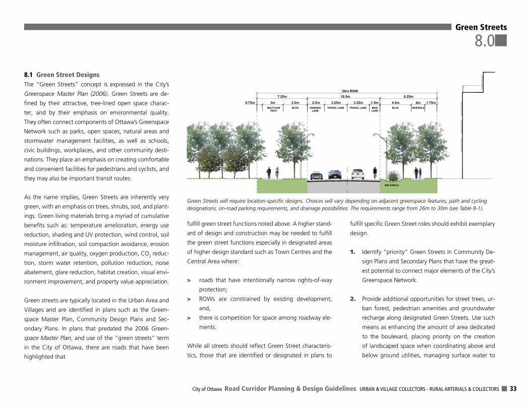
City of Ottawa Road Corridor Planning & Design Guidelines URBAN & VILLAGE COLLECTORS - RURAL ARTERIALS & COLLECTORS 33
8.1 Green Street DesignsThe “Green Streets” concept is expressed in the City’s
Greenspace Master Plan (2006). Green Streets are de-
fined by their attractive, tree-lined open space charac-
ter, and by their emphasis on environmental quality.
They often connect components of Ottawa’s Greenspace
Network such as parks, open spaces, natural areas and
stormwater management facilities, as well as schools,
civic buildings, workplaces, and other community desti-
nations. They place an emphasis on creating comfortable
and convenient facilities for pedestrians and cyclists, and
they may also be important transit routes.
As the name implies, Green Streets are inherently very
green, with an emphasis on trees, shrubs, sod, and plant-
ings. Green living materials bring a myriad of cumulative
benefits such as: temperature amelioration, energy use
reduction, shading and UV protection, wind control, soil
moisture infiltration, soil compaction avoidance, erosion
management, air quality, oxygen production, CO2 reduc-
tion, storm water retention, pollution reduction, noise
abatement, glare reduction, habitat creation, visual envi-
ronment improvement, and property value appreciation.
Green streets are typically located in the Urban Area and
Villages and are identified in plans such as the Green-
space Master Plan, Community Design Plans and Sec-
ondary Plans. In plans that predated the 2006 Green-
space Master Plan, and use of the “green streets” term
in the City of Ottawa, there are roads that have been
highlighted that
fulfill green street functions noted above. A higher stand-
ard of design and construction may be needed to fulfill
the green street functions especially in designated areas
of higher design standard such as Town Centres and the
Central Area where:
> roads that have intentionally narrow rights-of-way
protection;
> ROWs are constrained by existing development;
and,
> there is competition for space among roadway ele-
ments.
While all streets should reflect Green Street characteris-
tics, those that are identified or designated in plans to
fulfill specific Green Street roles should exhibit exemplary
design.
1. Identify “priority” Green Streets in Community De-
sign Plans and Secondary Plans that have the great-
est potential to connect major elements of the City’s
Greenspace Network.
2. Provide additional opportunities for street trees, ur-
ban forest, pedestrian amenities and groundwater
recharge along designated Green Streets. Use such
means as enhancing the amount of area dedicated
to the boulevard, placing priority on the creation
of landscaped space when coordinating above and
below ground utilities, managing surface water to
Green Streets
8.0
MULTI-USE PATH
SIDEWALK BLVD.
ROW
BLVD. PARKING LANE
TRAVEL LANE TRAVEL LANE BIKE LANE
BIO-SWALE
Green Streets will require location-specific designs. Choices will vary depending on adjacent greenspace features, path and cycling designations, on-road parking requirements, and drainage possibilities. The requirements range from 26m to 30m (see Table 8-1).
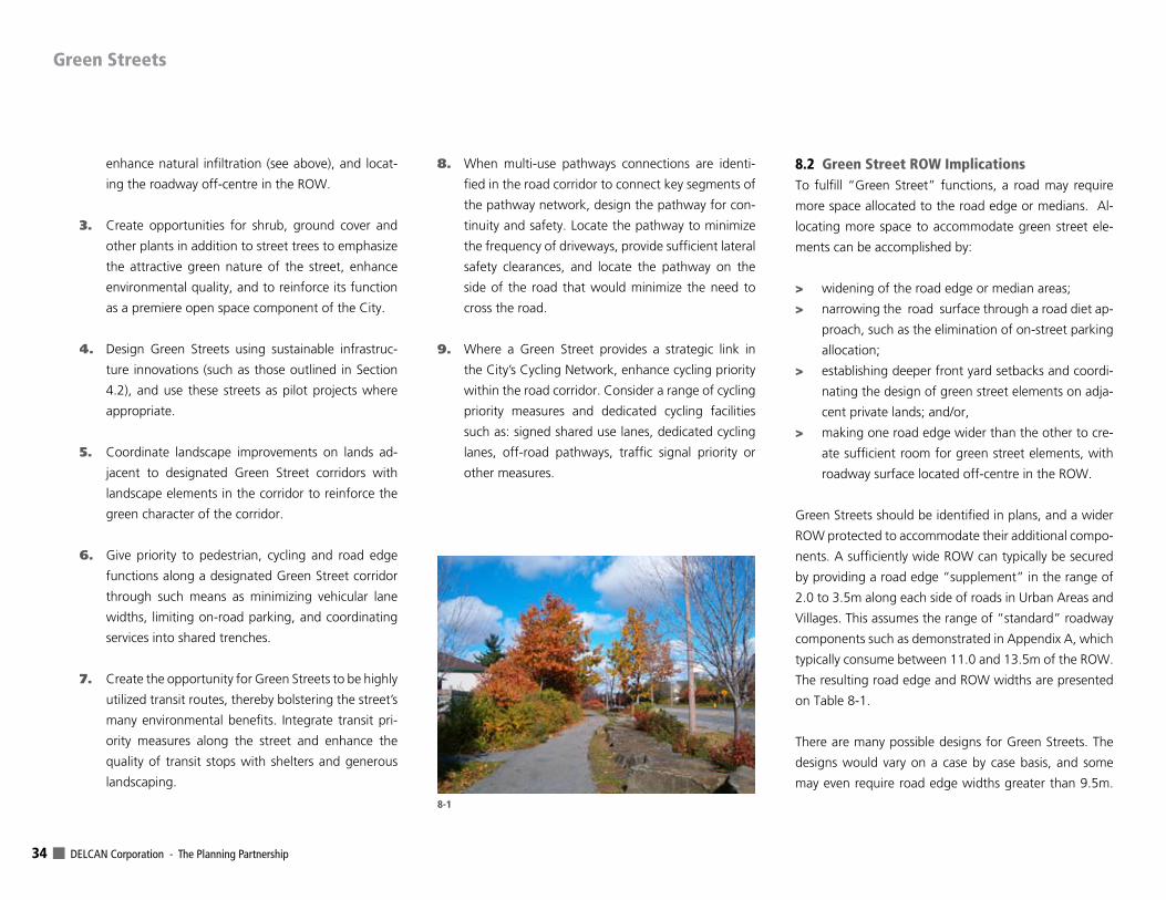
DELCAN Corporation - The Planning Partnership 34
enhance natural infiltration (see above), and locat-
ing the roadway off-centre in the ROW.
3. Create opportunities for shrub, ground cover and
other plants in addition to street trees to emphasize
the attractive green nature of the street, enhance
environmental quality, and to reinforce its function
as a premiere open space component of the City.
4. Design Green Streets using sustainable infrastruc-
ture innovations (such as those outlined in Section
4.2), and use these streets as pilot projects where
appropriate.
5. Coordinate landscape improvements on lands ad-
jacent to designated Green Street corridors with
landscape elements in the corridor to reinforce the
green character of the corridor.
6. Give priority to pedestrian, cycling and road edge
functions along a designated Green Street corridor
through such means as minimizing vehicular lane
widths, limiting on-road parking, and coordinating
services into shared trenches.
7. Create the opportunity for Green Streets to be highly
utilized transit routes, thereby bolstering the street’s
many environmental benefits. Integrate transit pri-
ority measures along the street and enhance the
quality of transit stops with shelters and generous
landscaping.
8. When multi-use pathways connections are identi-
fied in the road corridor to connect key segments of
the pathway network, design the pathway for con-
tinuity and safety. Locate the pathway to minimize
the frequency of driveways, provide sufficient lateral
safety clearances, and locate the pathway on the
side of the road that would minimize the need to
cross the road.
9. Where a Green Street provides a strategic link in
the City’s Cycling Network, enhance cycling priority
within the road corridor. Consider a range of cycling
priority measures and dedicated cycling facilities
such as: signed shared use lanes, dedicated cycling
lanes, off-road pathways, traffic signal priority or
other measures.
8.2 Green Street ROW ImplicationsTo fulfill “Green Street” functions, a road may require
more space allocated to the road edge or medians. Al-
locating more space to accommodate green street ele-
ments can be accomplished by:
> widening of the road edge or median areas;
> narrowing the road surface through a road diet ap-
proach, such as the elimination of on-street parking
allocation;
> establishing deeper front yard setbacks and coordi-
nating the design of green street elements on adja-
cent private lands; and/or,
> making one road edge wider than the other to cre-
ate sufficient room for green street elements, with
roadway surface located off-centre in the ROW.
Green Streets should be identified in plans, and a wider
ROW protected to accommodate their additional compo-
nents. A sufficiently wide ROW can typically be secured
by providing a road edge “supplement” in the range of
2.0 to 3.5m along each side of roads in Urban Areas and
Villages. This assumes the range of “standard” roadway
components such as demonstrated in Appendix A, which
typically consume between 11.0 and 13.5m of the ROW.
The resulting road edge and ROW widths are presented
on Table 8-1.
There are many possible designs for Green Streets. The
designs would vary on a case by case basis, and some
may even require road edge widths greater than 9.5m.
Green Streets
8-1
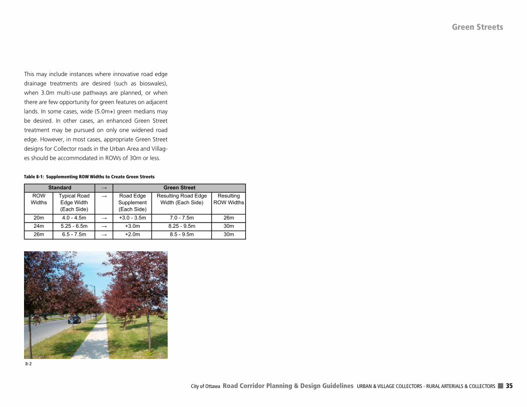
City of Ottawa Road Corridor Planning & Design Guidelines URBAN & VILLAGE COLLECTORS - RURAL ARTERIALS & COLLECTORS 35
This may include instances where innovative road edge
drainage treatments are desired (such as bioswales),
when 3.0m multi-use pathways are planned, or when
there are few opportunity for green features on adjacent
lands. In some cases, wide (5.0m+) green medians may
be desired. In other cases, an enhanced Green Street
treatment may be pursued on only one widened road
edge. However, in most cases, appropriate Green Street
designs for Collector roads in the Urban Area and Villag-
es should be accommodated in ROWs of 30m or less.
ROWWidths
Typical Road Edge Width (Each Side)
Road Edge Supplement(Each Side)
Resulting Road Edge Width (Each Side)
ResultingROW Widths
20m 4.0 - 4.5m +3.0 - 3.5m 7.0 - 7.5m 26m24m 5.25 - 6.5m +3.0m 8.25 - 9.5m 30m26m 6.5 - 7.5m +2.0m 8.5 - 9.5m 30m
Standard Green Street
Table 8-1: Supplementing ROW Widths to Create Green Streets
8-2
Green Streets
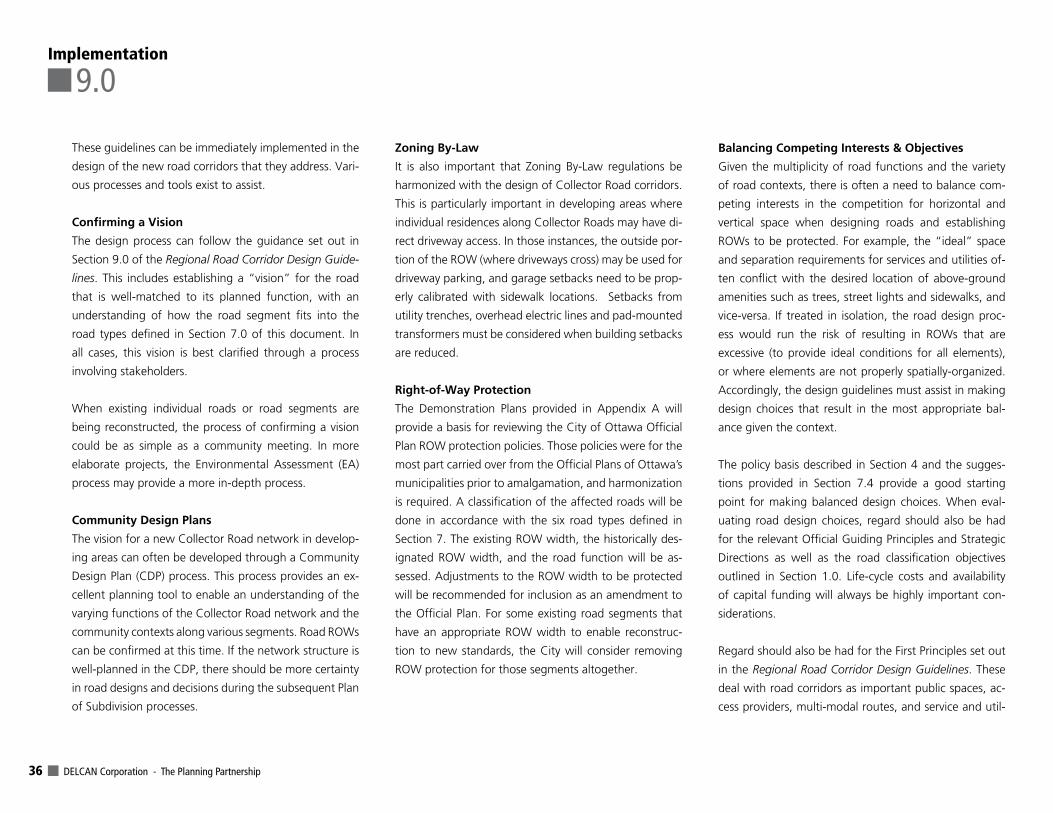
DELCAN Corporation - The Planning Partnership 36
These guidelines can be immediately implemented in the
design of the new road corridors that they address. Vari-
ous processes and tools exist to assist.
Confirming a Vision
The design process can follow the guidance set out in
Section 9.0 of the Regional Road Corridor Design Guide-
lines. This includes establishing a “vision” for the road
that is well-matched to its planned function, with an
understanding of how the road segment fits into the
road types defined in Section 7.0 of this document. In
all cases, this vision is best clarified through a process
involving stakeholders.
When existing individual roads or road segments are
being reconstructed, the process of confirming a vision
could be as simple as a community meeting. In more
elaborate projects, the Environmental Assessment (EA)
process may provide a more in-depth process.
Community Design Plans
The vision for a new Collector Road network in develop-
ing areas can often be developed through a Community
Design Plan (CDP) process. This process provides an ex-
cellent planning tool to enable an understanding of the
varying functions of the Collector Road network and the
community contexts along various segments. Road ROWs
can be confirmed at this time. If the network structure is
well-planned in the CDP, there should be more certainty
in road designs and decisions during the subsequent Plan
of Subdivision processes.
Zoning By-Law
It is also important that Zoning By-Law regulations be
harmonized with the design of Collector Road corridors.
This is particularly important in developing areas where
individual residences along Collector Roads may have di-
rect driveway access. In those instances, the outside por-
tion of the ROW (where driveways cross) may be used for
driveway parking, and garage setbacks need to be prop-
erly calibrated with sidewalk locations. Setbacks from
utility trenches, overhead electric lines and pad-mounted
transformers must be considered when building setbacks
are reduced.
Right-of-Way Protection
The Demonstration Plans provided in Appendix A will
provide a basis for reviewing the City of Ottawa Official
Plan ROW protection policies. Those policies were for the
most part carried over from the Official Plans of Ottawa’s
municipalities prior to amalgamation, and harmonization
is required. A classification of the affected roads will be
done in accordance with the six road types defined in
Section 7. The existing ROW width, the historically des-
ignated ROW width, and the road function will be as-
sessed. Adjustments to the ROW width to be protected
will be recommended for inclusion as an amendment to
the Official Plan. For some existing road segments that
have an appropriate ROW width to enable reconstruc-
tion to new standards, the City will consider removing
ROW protection for those segments altogether.
Balancing Competing Interests & Objectives
Given the multiplicity of road functions and the variety
of road contexts, there is often a need to balance com-
peting interests in the competition for horizontal and
vertical space when designing roads and establishing
ROWs to be protected. For example, the “ideal” space
and separation requirements for services and utilities of-
ten conflict with the desired location of above-ground
amenities such as trees, street lights and sidewalks, and
vice-versa. If treated in isolation, the road design proc-
ess would run the risk of resulting in ROWs that are
excessive (to provide ideal conditions for all elements),
or where elements are not properly spatially-organized.
Accordingly, the design guidelines must assist in making
design choices that result in the most appropriate bal-
ance given the context.
The policy basis described in Section 4 and the sugges-
tions provided in Section 7.4 provide a good starting
point for making balanced design choices. When eval-
uating road design choices, regard should also be had
for the relevant Official Guiding Principles and Strategic
Directions as well as the road classification objectives
outlined in Section 1.0. Life-cycle costs and availability
of capital funding will always be highly important con-
siderations.
Regard should also be had for the First Principles set out
in the Regional Road Corridor Design Guidelines. These
deal with road corridors as important public spaces, ac-
cess providers, multi-modal routes, and service and util-
Implementation
9.0
City of Ottawa Road Corridor Planning & Design Guidelines URBAN & VILLAGE COLLECTORS - RURAL ARTERIALS & COLLECTORS 37
ity routes. How do alternative designs meet all of these
criteria? A holistic understanding of these varying road
objectives and a constant consideration of trade-offs and
innovative solutions is required.
Finally, the City will be informed by these guidelines
when preparing and updating its road design manuals,
specifications, detailed cross-sections, and in preparing
site-specific designs. Those tools will establish municipal
standards governing construction, and will be effective in
promoting designs for all above-grade and below-grade
infrastructure that are compatible with the planning and
design guidance provided in this document and other
related city documents.
Implementation

DELCAN Corporation - The Planning Partnership 38
City of Ottawa Road Corridor Planning & Design Guidelines URBAN & VILLAGE COLLECTORS - RURAL ARTERIALS & COLLECTORS 39
APPENDIX A includes the following demonstration cross-
sections and right-of-way width requirements:
Neighbourhood Collector20m ROW
22m ROW
24m ROW - Option 1 - Standard
24m ROW - Option 2 - Trees Between Sidewalk & Curb
26m ROW
Village Collector26m ROW
Community Collector20m ROW
24m ROW
26m ROW - Option 1 - Standard
26m ROW - Option 2 - Cycling Lanes
26m ROW - Option 3 - Enhanced Areas
Business Area Collector26m ROW
Rural Collector26m ROW
Rural Arterial30m ROW
Note that these designs are merely demonstrations and need to be tested and refined by stakeholders following a detailed design process. In the interim, designs need to reference the latest version of the City of Ottawa and utilities’ technical design guidelines, standards and specifications.
ADemonstration Cross-Sections & Right-of-way Width Requirements
A
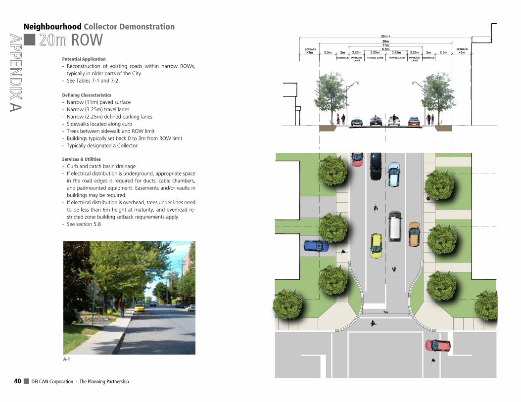
DELCAN Corporation - The Planning Partnership 40
Neighbourhood Collector Demonstration
SIDEWALK SIDEWALKPARKINGLANE
PARKINGLANE
TRAVEL LANE TRAVEL LANE
SETBACK SETBACK
ROW
A
Potential Application
- Reconstruction of existing roads within narrow ROWs, typically in older parts of the City.
- See Tables 7-1 and 7-2.
DefiningCharacteristics
- Narrow (11m) paved surface- Narrow (3.25m) travel lanes- Narrow (2.25m) defined parking lanes- Sidewalks located along curb- Trees between sidewalk and ROW limit- Buildings typically set back 0 to 3m from ROW limit - Typically designated a Collector
Services & Utilities
- Curb and catch basin drainage- If electrical distribution is underground, appropriate space
in the road edges is required for ducts, cable chambers, and padmounted equipment. Easements and/or vaults in buildings may be required.
- If electrical distribution is overhead, trees under lines need to be less than 6m height at maturity, and overhead re-stricted zone building setback requirements apply.
- See section 5.8
A-1
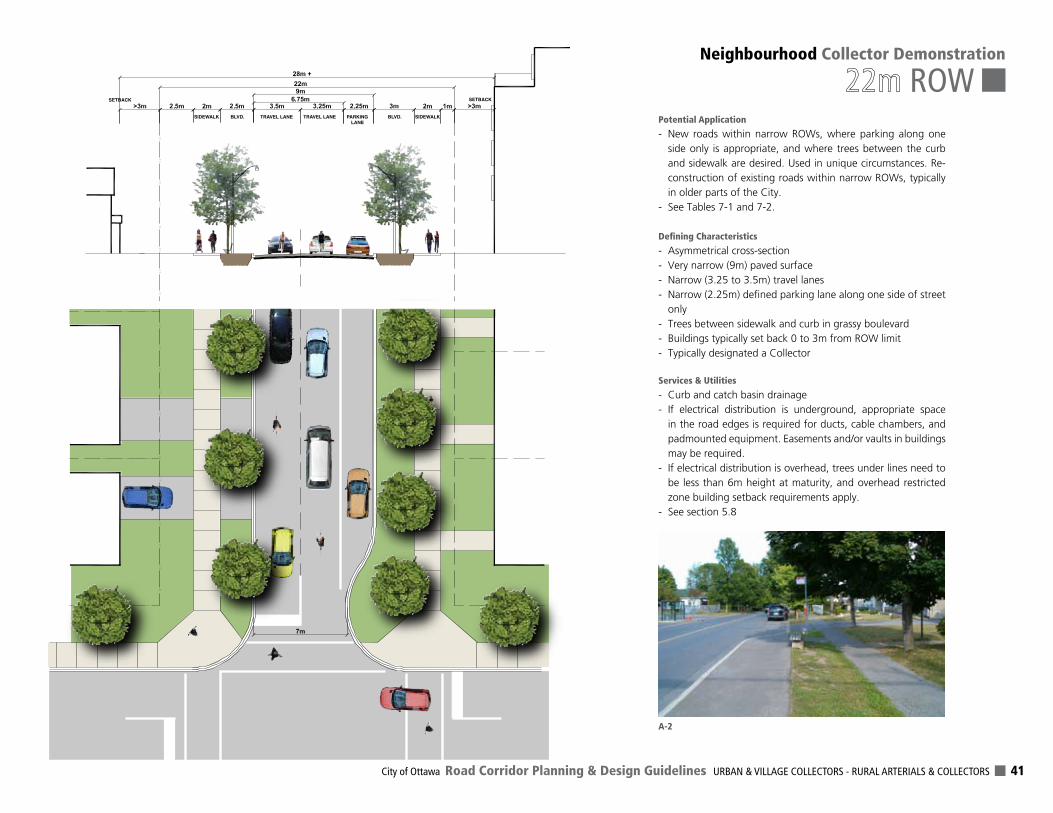
City of Ottawa Road Corridor Planning & Design Guidelines URBAN & VILLAGE COLLECTORS - RURAL ARTERIALS & COLLECTORS 41
Neighbourhood Collector Demonstration
ROWSIDEWALK SIDEWALKBLVD. BLVD.PARKING
LANETRAVEL LANE TRAVEL LANE
SETBACK SETBACK
A-2
Potential Application
- New roads within narrow ROWs, where parking along one side only is appropriate, and where trees between the curb and sidewalk are desired. Used in unique circumstances. Re-construction of existing roads within narrow ROWs, typically in older parts of the City.
- See Tables 7-1 and 7-2.
DefiningCharacteristics
- Asymmetrical cross-section- Very narrow (9m) paved surface- Narrow (3.25 to 3.5m) travel lanes- Narrow (2.25m) defined parking lane along one side of street
only- Trees between sidewalk and curb in grassy boulevard- Buildings typically set back 0 to 3m from ROW limit - Typically designated a Collector
Services & Utilities
- Curb and catch basin drainage- If electrical distribution is underground, appropriate space
in the road edges is required for ducts, cable chambers, and padmounted equipment. Easements and/or vaults in buildings may be required.
- If electrical distribution is overhead, trees under lines need to be less than 6m height at maturity, and overhead restricted zone building setback requirements apply.
- See section 5.8
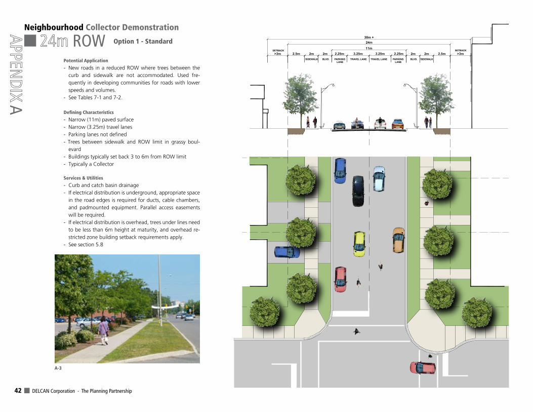
DELCAN Corporation - The Planning Partnership 42
Neighbourhood Collector Demonstration
ROW
A
Option 1 - Standard
SIDEWALK SIDEWALKBLVD. BLVD.
SETBACK SETBACK
PARKINGLANE
PARKINGLANE
TRAVEL LANE TRAVEL LANE
A-3
Potential Application
- New roads in a reduced ROW where trees between the curb and sidewalk are not accommodated. Used fre-quently in developing communities for roads with lower speeds and volumes.
- See Tables 7-1 and 7-2.
DefiningCharacteristics
- Narrow (11m) paved surface- Narrow (3.25m) travel lanes- Parking lanes not defined- Trees between sidewalk and ROW limit in grassy boul-
evard- Buildings typically set back 3 to 6m from ROW limit - Typically a Collector
Services & Utilities
- Curb and catch basin drainage- If electrical distribution is underground, appropriate space
in the road edges is required for ducts, cable chambers, and padmounted equipment. Parallel access easements will be required.
- If electrical distribution is overhead, trees under lines need to be less than 6m height at maturity, and overhead re-stricted zone building setback requirements apply.
- See section 5.8
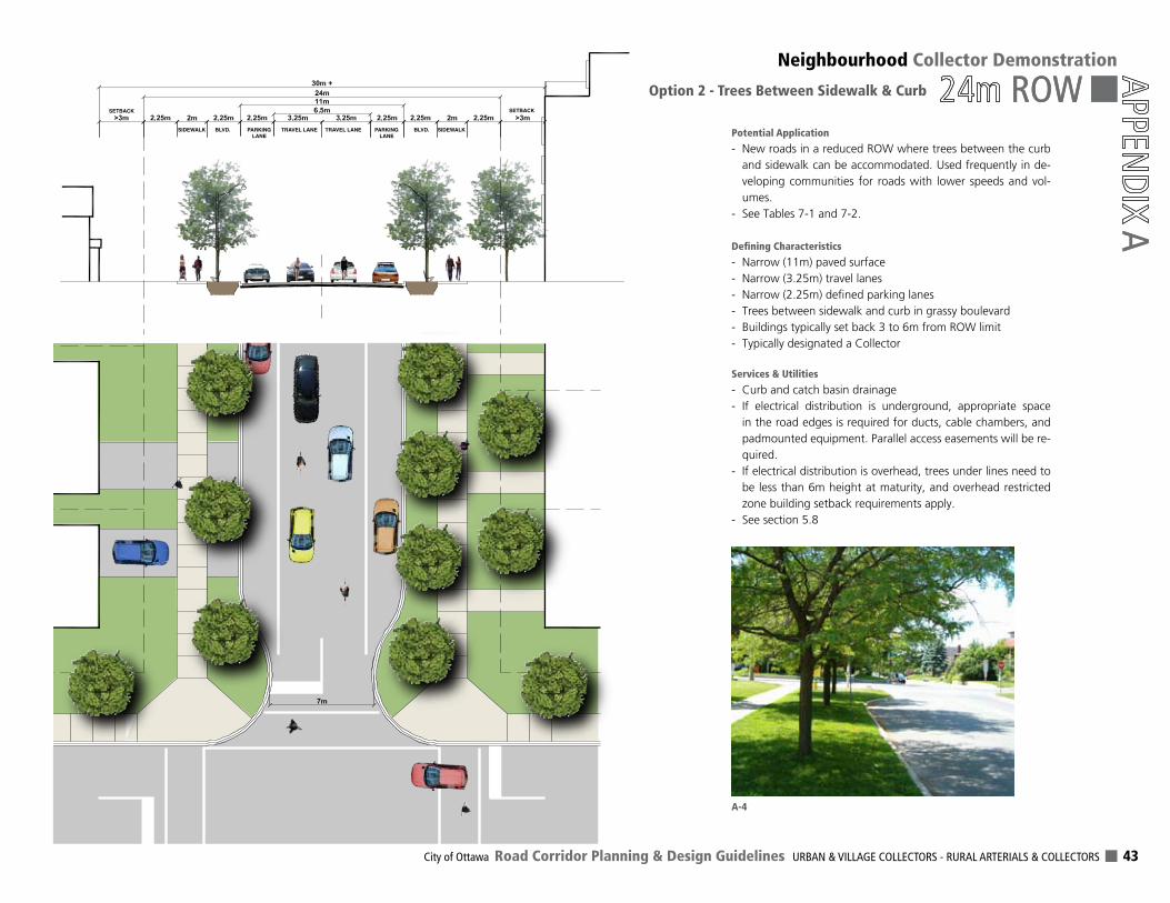
City of Ottawa Road Corridor Planning & Design Guidelines URBAN & VILLAGE COLLECTORS - RURAL ARTERIALS & COLLECTORS 43
ROWNeighbourhood Collector Demonstration
ROW
AOption 2 - Trees Between Sidewalk & Curb
SIDEWALK SIDEWALKBLVD. BLVD.PARKINGLANE
PARKINGLANE
TRAVEL LANE TRAVEL LANE
SETBACK SETBACK
A
A-4
Potential Application
- New roads in a reduced ROW where trees between the curb and sidewalk can be accommodated. Used frequently in de-veloping communities for roads with lower speeds and vol-umes.
- See Tables 7-1 and 7-2.
DefiningCharacteristics
- Narrow (11m) paved surface- Narrow (3.25m) travel lanes- Narrow (2.25m) defined parking lanes- Trees between sidewalk and curb in grassy boulevard- Buildings typically set back 3 to 6m from ROW limit - Typically designated a Collector
Services & Utilities
- Curb and catch basin drainage- If electrical distribution is underground, appropriate space
in the road edges is required for ducts, cable chambers, and padmounted equipment. Parallel access easements will be re-quired.
- If electrical distribution is overhead, trees under lines need to be less than 6m height at maturity, and overhead restricted zone building setback requirements apply.
- See section 5.8
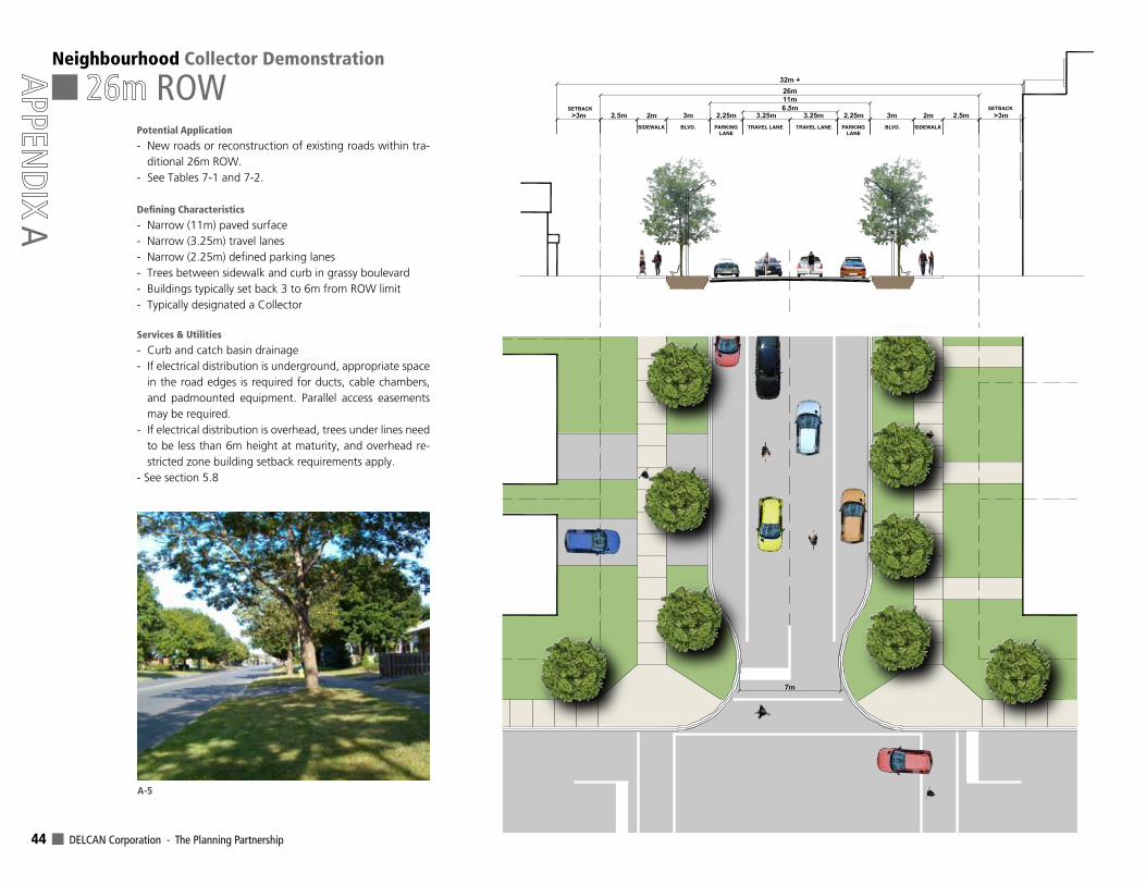
DELCAN Corporation - The Planning Partnership 44
SIDEWALK SIDEWALKBLVD. BLVD.PARKINGLANE
PARKINGLANE
TRAVEL LANE TRAVEL LANE
SETBACK SETBACK
Neighbourhood Collector Demonstration
ROW
A
A-5
Potential Application
- New roads or reconstruction of existing roads within tra-ditional 26m ROW.
- See Tables 7-1 and 7-2.
DefiningCharacteristics
- Narrow (11m) paved surface- Narrow (3.25m) travel lanes- Narrow (2.25m) defined parking lanes- Trees between sidewalk and curb in grassy boulevard- Buildings typically set back 3 to 6m from ROW limit - Typically designated a Collector
Services & Utilities
- Curb and catch basin drainage- If electrical distribution is underground, appropriate space
in the road edges is required for ducts, cable chambers, and padmounted equipment. Parallel access easements may be required.
- If electrical distribution is overhead, trees under lines need to be less than 6m height at maturity, and overhead re-stricted zone building setback requirements apply.
- See section 5.8
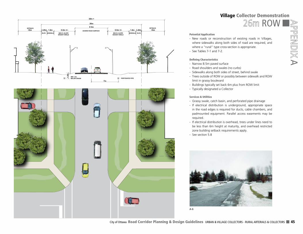
City of Ottawa Road Corridor Planning & Design Guidelines URBAN & VILLAGE COLLECTORS - RURAL ARTERIALS & COLLECTORS 45
Village Collector Demonstration
ROW
A
SIDEWALKBLVD. BLVD.SIDEWALKMIN 6% SLOPEGRASSY SWALE
MIN 1.5m BELOW GRADE
MIN 6% SLOPEGRASSY SWALE
SHARED ROAD SURFACE
PERFORATED PIPE
SETBACK SETBACK
A-6
Potential Application
- New roads or reconstruction of existing roads in Villages, where sidewalks along both sides of road are required, and where a “rural” type cross-section is appropriate.
- See Tables 7-1 and 7-2.
DefiningCharacteristics
- Narrow 8.5m paved surface- Road shoulders and swales (no curbs)- Sidewalks along both sides of street, behind swale- Trees outside of ROW or possibly between sidewalk and ROW
limit in grassy boulevard- Buildings typically set back 6m plus from ROW limit - Typically designated a Collector
Services & Utilities
- Grassy swale, catch basin, and perforated pipe drainage- If electrical distribution is underground, appropriate space
in the road edges is required for ducts, cable chambers, and padmounted equipment. Parallel access easements may be required.
- If electrical distribution is overhead, trees under lines need to be less than 6m height at maturity, and overhead restricted zone building setback requirements apply.
- See section 5.8
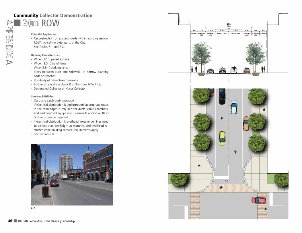
DELCAN Corporation - The Planning Partnership 46
SIDEWALK SIDEWALKPLANTINGBED
PLANTINGBED
PARKINGLANE
PARKINGLANE
TRAVEL LANE TRAVEL LANE
Community Collector Demonstration
ROW
A
A-7
Potential Application
- Reconstruction of existing roads within existing narrow ROW, typically in older parts of the City.
- See Tables 7-1 and 7-2.
DefiningCharacteristics
- Wider (12m) paved surface- Wider (3.5m) travel lanes- Wide (2.5m) parking lanes- Trees between curb and sidewalk, in narrow planting
beds or trenches- Possibility of distinctive crosswalks- Buildings typically set back 0 to 3m from ROW limit - Designated Collector or Major Collector
Services & Utilities
- Curb and catch basin drainage- If electrical distribution is underground, appropriate space
in the road edges is required for ducts, cable chambers, and padmounted equipment. Easements and/or vaults in buildings may be required.
- If electrical distribution is overhead, trees under lines need to be less than 6m height at maturity, and overhead re-stricted zone building setback requirements apply.
- See section 5.8
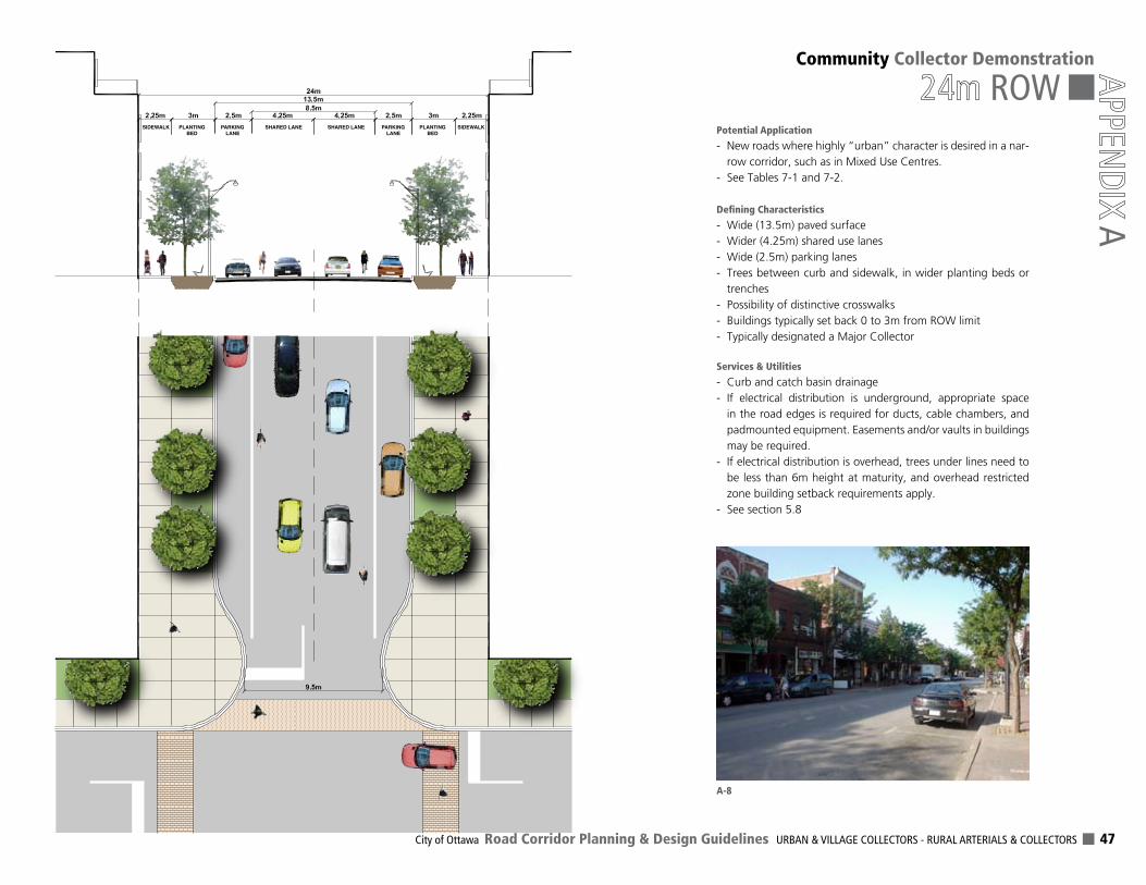
City of Ottawa Road Corridor Planning & Design Guidelines URBAN & VILLAGE COLLECTORS - RURAL ARTERIALS & COLLECTORS 47
Community Collector Demonstration
ROW
A
SIDEWALK SIDEWALKPLANTINGBED
PLANTINGBED
PARKINGLANE
PARKINGLANE
SHARED LANE SHARED LANE
A-8
Potential Application
- New roads where highly “urban” character is desired in a nar-row corridor, such as in Mixed Use Centres.
- See Tables 7-1 and 7-2.
DefiningCharacteristics
- Wide (13.5m) paved surface- Wider (4.25m) shared use lanes- Wide (2.5m) parking lanes- Trees between curb and sidewalk, in wider planting beds or
trenches- Possibility of distinctive crosswalks- Buildings typically set back 0 to 3m from ROW limit - Typically designated a Major Collector
Services & Utilities
- Curb and catch basin drainage- If electrical distribution is underground, appropriate space
in the road edges is required for ducts, cable chambers, and padmounted equipment. Easements and/or vaults in buildings may be required.
- If electrical distribution is overhead, trees under lines need to be less than 6m height at maturity, and overhead restricted zone building setback requirements apply.
- See section 5.8
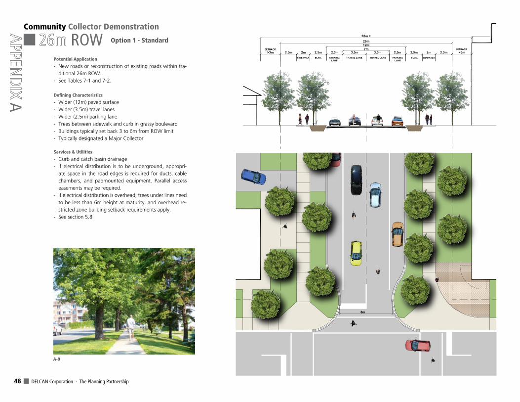
DELCAN Corporation - The Planning Partnership 48
Community Collector Demonstration
ROW
A
Option 1 - Standard
SIDEWALK SIDEWALKBLVD. BLVD.PARKINGLANE
PARKINGLANE
TRAVEL LANE TRAVEL LANE
SETBACK SETBACK
A-9
Potential Application
- New roads or reconstruction of existing roads within tra-ditional 26m ROW.
- See Tables 7-1 and 7-2.
DefiningCharacteristics
- Wider (12m) paved surface- Wider (3.5m) travel lanes- Wider (2.5m) parking lane- Trees between sidewalk and curb in grassy boulevard- Buildings typically set back 3 to 6m from ROW limit - Typically designated a Major Collector
Services & Utilities
- Curb and catch basin drainage- If electrical distribution is to be underground, appropri-
ate space in the road edges is required for ducts, cable chambers, and padmounted equipment. Parallel access easements may be required.
- If electrical distribution is overhead, trees under lines need to be less than 6m height at maturity, and overhead re-stricted zone building setback requirements apply.
- See section 5.8
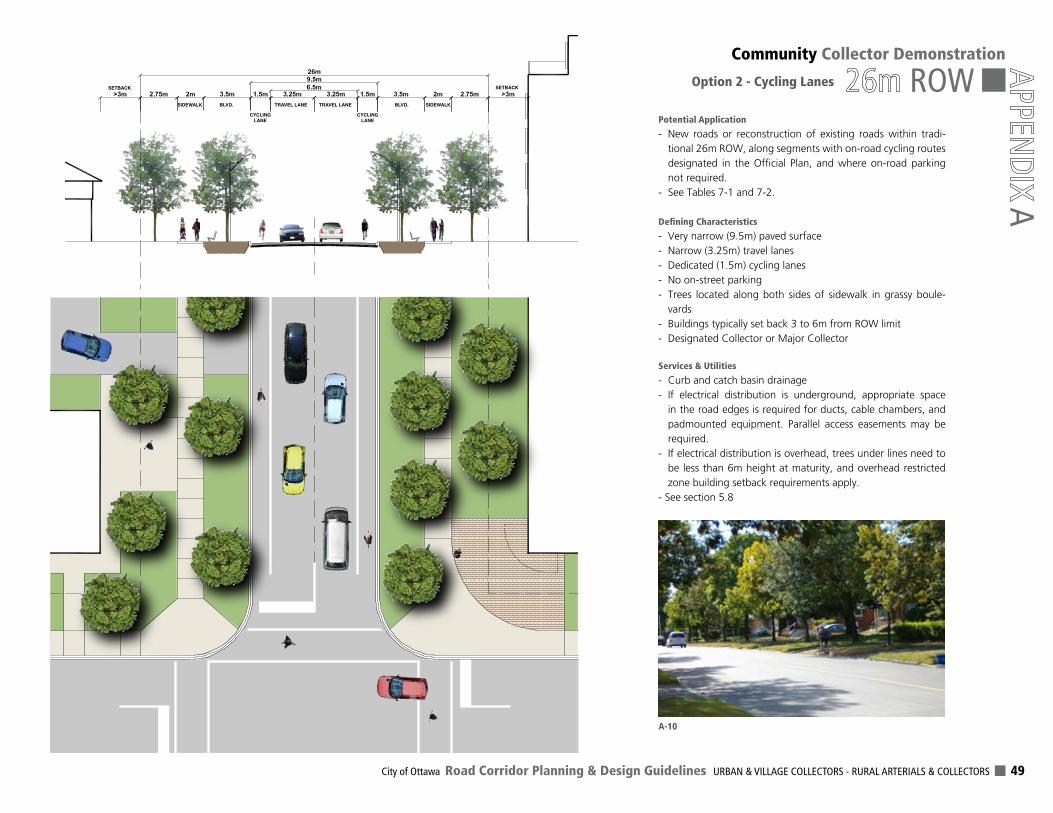
City of Ottawa Road Corridor Planning & Design Guidelines URBAN & VILLAGE COLLECTORS - RURAL ARTERIALS & COLLECTORS 49
Community Collector Demonstration
ROW
AOption 2 - Cycling Lanes
SIDEWALK SIDEWALKBLVD. BLVD.
CYCLINGLANE
CYCLINGLANE
TRAVEL LANE TRAVEL LANE
SETBACK SETBACK
A-10
Potential Application
- New roads or reconstruction of existing roads within tradi-tional 26m ROW, along segments with on-road cycling routes designated in the Official Plan, and where on-road parking not required.
- See Tables 7-1 and 7-2.
DefiningCharacteristics
- Very narrow (9.5m) paved surface- Narrow (3.25m) travel lanes- Dedicated (1.5m) cycling lanes- No on-street parking- Trees located along both sides of sidewalk in grassy boule-
vards- Buildings typically set back 3 to 6m from ROW limit - Designated Collector or Major Collector
Services & Utilities
- Curb and catch basin drainage- If electrical distribution is underground, appropriate space
in the road edges is required for ducts, cable chambers, and padmounted equipment. Parallel access easements may be required.
- If electrical distribution is overhead, trees under lines need to be less than 6m height at maturity, and overhead restricted zone building setback requirements apply.
- See section 5.8
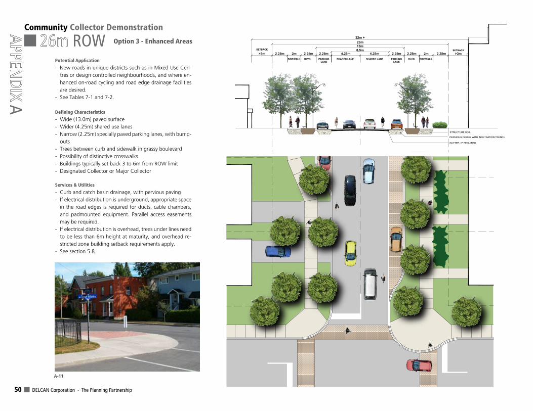
DELCAN Corporation - The Planning Partnership 50
Community Collector Demonstration
ROW
A
Option 3 - Enhanced Areas
SIDEWALK SIDEWALKBLVD. BLVD.PARKINGLANE
PARKINGLANE
SHARED LANE SHARED LANE
SETBACK SETBACK
STRUCTURE SOIL
PERVIOUS PAVING WITH INFILTRATION TRENCH
GUTTER, IF REQUIRED
A-11
Potential Application
- New roads in unique districts such as in Mixed Use Cen-tres or design controlled neighbourhoods, and where en-hanced on-road cycling and road edge drainage facilities are desired.
- See Tables 7-1 and 7-2.
DefiningCharacteristics
- Wide (13.0m) paved surface- Wider (4.25m) shared use lanes- Narrow (2.25m) specially paved parking lanes, with bump-
outs- Trees between curb and sidewalk in grassy boulevard- Possibility of distinctive crosswalks- Buildings typically set back 3 to 6m from ROW limit- Designated Collector or Major Collector
Services & Utilities
- Curb and catch basin drainage, with pervious paving- If electrical distribution is underground, appropriate space
in the road edges is required for ducts, cable chambers, and padmounted equipment. Parallel access easements may be required.
- If electrical distribution is overhead, trees under lines need to be less than 6m height at maturity, and overhead re-stricted zone building setback requirements apply.
- See section 5.8
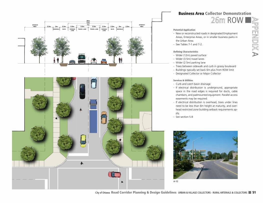
City of Ottawa Road Corridor Planning & Design Guidelines URBAN & VILLAGE COLLECTORS - RURAL ARTERIALS & COLLECTORS 51
Business Area Collector Demonstration
ROW
A
SIDEWALK SIDEWALKBLVD. BLVD.PARKINGLANE
PARKINGLANE
TRAVEL LANE TRAVEL LANE
SETBACK SETBACK
A-12
Potential Application
- New or reconstructed roads in designated Employment Areas, Enterprise Areas, or in smaller business parks in the Urban Area.
- See Tables 7-1 and 7-2.
DefiningCharacteristics
- Wider (12m) paved surface- Wider (3.5m) travel lanes- Wider (2.5m) parking lane- Trees between sidewalk and curb in grassy boulevard- Buildings typically set back 6m plus from ROW limit- Designated Collector or Major Collector
Services & Utilities
- Curb and catch basin drainage- If electrical distribution is underground, appropriate
space in the road edges is required for ducts, cable chambers, and padmounted equipment. Parallel access easements may be required.
- If electrical distribution is overhead, trees under lines need to be less than 6m height at maturity, and over-head restricted zone building setback requirements ap-ply.
- See section 5.8
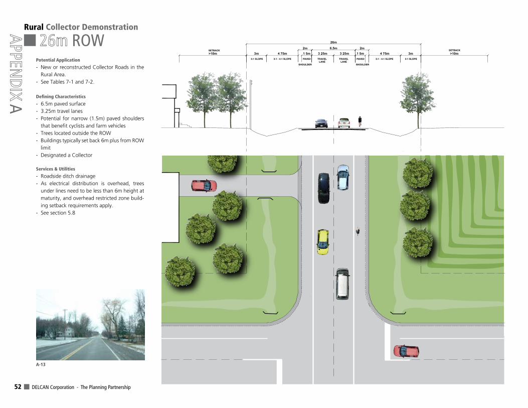
DELCAN Corporation - The Planning Partnership 52
3:1 SLOPE 3:1 SLOPE3:1 - 4:1 SLOPE 3:1 - 4:1 SLOPE
SHOULDER SHOULDER
TRAVELLANE
TRAVELLANE
SETBACK SETBACK
PAVEDPAVED
Rural Collector Demonstration
ROW
A
A-13
Potential Application
- New or reconstructed Collector Roads in the Rural Area.
- See Tables 7-1 and 7-2.
DefiningCharacteristics
- 6.5m paved surface- 3.25m travel lanes- Potential for narrow (1.5m) paved shoulders
that benefit cyclists and farm vehicles- Trees located outside the ROW- Buildings typically set back 6m plus from ROW
limit- Designated a Collector
Services & Utilities
- Roadside ditch drainage- As electrical distribution is overhead, trees
under lines need to be less than 6m height at maturity, and overhead restricted zone build-ing setback requirements apply.
- See section 5.8

City of Ottawa Road Corridor Planning & Design Guidelines URBAN & VILLAGE COLLECTORS - RURAL ARTERIALS & COLLECTORS 53
Rural Arterial Demonstration
ROW
A
3:1 SLOPE 3:1 SLOPE4:1 SLOPEPAVEDPAVED4:1 SLOPE
SHOULDER SHOULDER
TRAVELLANE
TRAVELLANE
SETBACK SETBACK
A-14
Potential Application
- New or reconstructed Arterial Roads in the Rural Area.
- See Tables 7-1 and 7-2.
DefiningCharacteristics
- 7.0m paved surface- 3.5m travel lanes- Potential for narrow (1.5m) paved
shoulders that benefit cyclists and farm vehicles
- Trees located outside the ROW- Buildings typically set back 6m plus
from ROW limit- Designated an Arterial
Services & Utilities
- Roadside ditch drainage- As electrical distribution is overhead,
trees under lines need to be less than 6m height at maturity, and overhead restricted zone building setback re-quirements apply.
- See section 5.8

DELCAN Corporation - The Planning Partnership 54
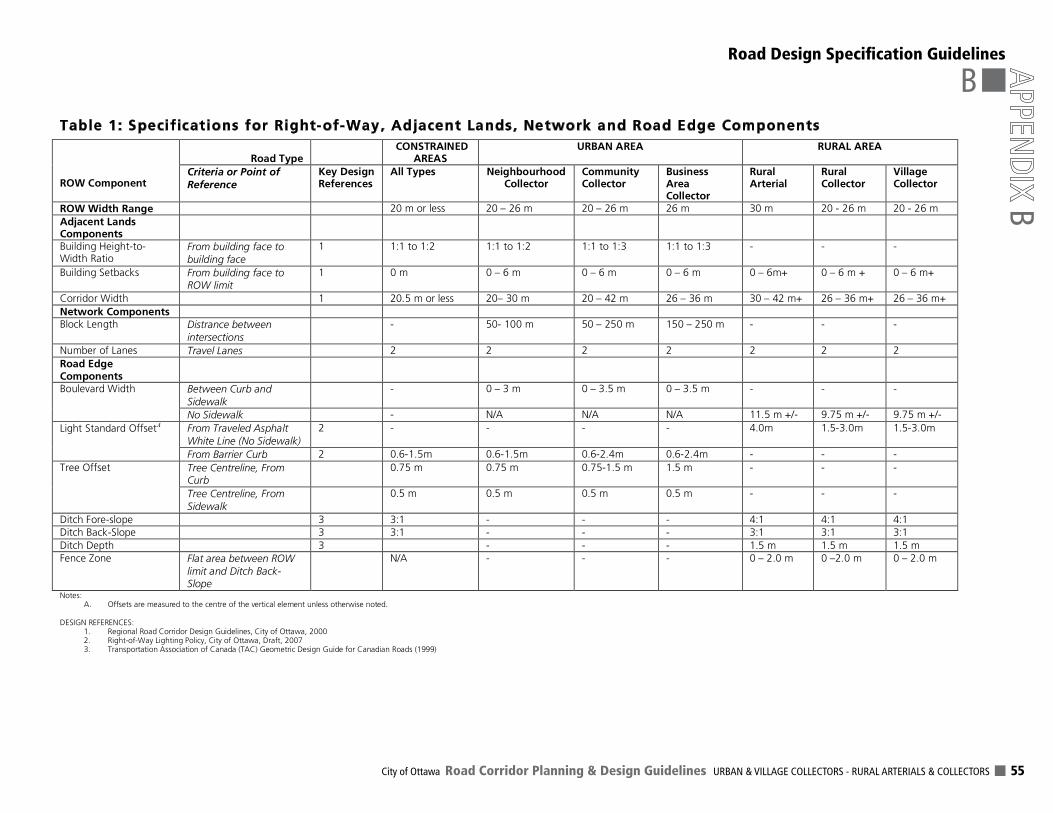
City of Ottawa Road Corridor Planning & Design Guidelines URBAN & VILLAGE COLLECTORS - RURAL ARTERIALS & COLLECTORS 55
B
BRoadDesignSpecificationGuidelines
Table 1: Specifications for Right-of-Way, Adjacent Lands, Network and Road Edge Components
Notes: A. Offsets are measured to the centre of the vertical element unless otherwise noted.
DESIGN REFERENCES: 1. Regional Road Corridor Design Guidelines, City of Ottawa, 2000 2. Right-of-Way Lighting Policy, City of Ottawa, Draft, 2007 3. Transportation Association of Canada (TAC) Geometric Design Guide for Canadian Roads (1999)
Road Type
CONSTRAINED AREAS
URBAN AREA
RURAL AREA ROW Component
Criteria or Point of
Reference
Key Design References
All Types Neighbourhood Collector
Community Collector
Business Area Collector
Rural Arterial
Rural Collector
Village Collector
ROW Width Range 20 m or less 20 – 26 m 20 – 26 m 26 m 30 m 20 - 26 m 20 - 26 m
Adjacent Lands Components
Building Height-to-Width Ratio
From building face to building face
1 1:1 to 1:2 1:1 to 1:2 1:1 to 1:3 1:1 to 1:3 - - -
Building Setbacks From building face to ROW limit
1 0 m 0 – 6 m 0 – 6 m 0 – 6 m 0 – 6m+ 0 – 6 m + 0 – 6 m+
Corridor Width 1 20.5 m or less 20– 30 m 20 – 42 m 26 – 36 m 30 – 42 m+ 26 – 36 m+ 26 – 36 m+
Network Components
Block Length Distrance between intersections
- 50- 100 m 50 – 250 m 150 – 250 m - - -
Number of Lanes Travel Lanes 2 2 2 2 2 2 2
Road Edge Components
Between Curb and Sidewalk
- 0 – 3 m 0 – 3.5 m 0 – 3.5 m - - - Boulevard Width
No Sidewalk - N/A N/A N/A 11.5 m +/- 9.75 m +/- 9.75 m +/-
From Traveled Asphalt White Line (No Sidewalk)
2 - - - - 4.0m 1.5-3.0m 1.5-3.0m Light Standard OffsetA
From Barrier Curb 2 0.6-1.5m 0.6-1.5m 0.6-2.4m 0.6-2.4m - - -
Tree Centreline, From Curb
0.75 m 0.75 m 0.75-1.5 m 1.5 m - - - Tree Offset
Tree Centreline, From Sidewalk
0.5 m 0.5 m 0.5 m 0.5 m - - -
Ditch Fore-slope 3 3:1 - - - 4:1 4:1 4:1
Ditch Back-Slope 3 3:1 - - - 3:1 3:1 3:1
Ditch Depth 3 - - - 1.5 m 1.5 m 1.5 m
Fence Zone Flat area between ROW limit and Ditch Back-Slope
N/A - - - 0 – 2.0 m 0 –2.0 m 0 – 2.0 m
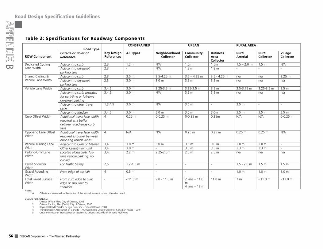
DELCAN Corporation - The Planning Partnership 56
B
RoadDesignSpecificationGuidelines
Table 2: Specifications for Roadway Components
Road Type
CONSTRAINED URBAN
RURAL AREA ROW Component
Criteria or Point of
Reference
Key Design References
All Types Neighbourhood Collector
Community Collector
Business Area Collector
Rural Arterial
Rural Collector
Village Collector
Adjacent to curb 2,3 1.2m N/A 1.5m 1.5m 1.5 – 2.0 m 1.5 m N/A Dedicated Cycling Lane Width Adjacent to on-street
parking lane
2,3 - N/A 1.8 m 1.8 m - - -
Adjacent to curb 2,3 3.5 m 3.5-4.25 m 3.5 – 4.25 m 3.5 - 4.25 m n/a n/a 3.25 m Shared Cycling & Vehicle Lane Width Adjacent to on-street
parking lane
2,3 3.0 m 3.0 m 3.5 m 3.5 m n/a n/a n/a
Adjacent to curb 3,4,5 3.0 m 3.25-3.5 m 3.25-3.5 m 3.5 m 3.5-3.75 m 3.25-3.5 m 3.5 m
Adjacent to curb, provides for part-time or full-time on-street parking
3,4,5 3.0 m N/A 3.5 m 3.5 m n/a n/a n/a
Adjacent to other travel Lane
1,3,4,5 3.0 m N/A 3.0 m - 3.5 m - -
Vehicle Lane Width
Adjacent to Median 3,4,5 3.0 m 3.0 m 3.0 m 3.0m 3.5 m 3.5 m 3.5 m
Curb Offset Width Additional travel lane width required as a buffer between road edge curb face
4 0.25 m 0-0.25 m 0-0.25 m 0.25m N/A N/A 0-0.25 m
Opposing Lane Offset Width
Additional travel lane width required as buffer between opposing vehicle lanes
4 N/A N/A 0.25 m 0.25 m 0.25 m 0.25 m N/A
Adjacent to Curb or Median 3,4 3.0 m 3.0 m 3.0 m 3.0 m 3.0 m 3.0 m - Vehicle Turning Lane Width Other Cases(minimum) 3,4 3.0 m - 3.3 m 3.3 m 3.3 m 3.3 m -
Parking-Only Lane Width
Located along curb, full-time vehicle parking, no cycling
3,4 2.2 m 2.25-2.5m 2.5 m 2.5 m n/a n/a n/a
Paved Shoulder Width
For Traffic Safety 2,5 1.2-1.5 m - - - 1.5 - 2.0 m 1.5 m 1.5 m
Gravel Rounding Width
From edge of asphalt 4 0.5 m - - - 1.0 m 1.0 m 1.0 m
Total Paved Surface Width
From curb edge to curb edge or shoulder to shoulder
- <11.0 m 9.0 - 11.0 m 2 lane – 11.0 m 4 lane – 13 m
11.0 m 7 m <11.0 m <11.0 m
Notes: A. Offsets are measured to the centre of the vertical element unless otherwise noted.
DESIGN REFERENCES: 1. Ottawa Official Plan, City of Ottawa, 2003 2. Ottawa Cyclilng Plan [Draft], City of Ottawa, 2005 3. Regional Road Corridor Design Guidelines, City of Ottawa, 2000 4. Transportation Association of Canada (TAC) Geometric Design Guide for Canadian Roads (1999) 5. Ontario Ministry of Transportation Geometric Deign Standards for Ontario Highways
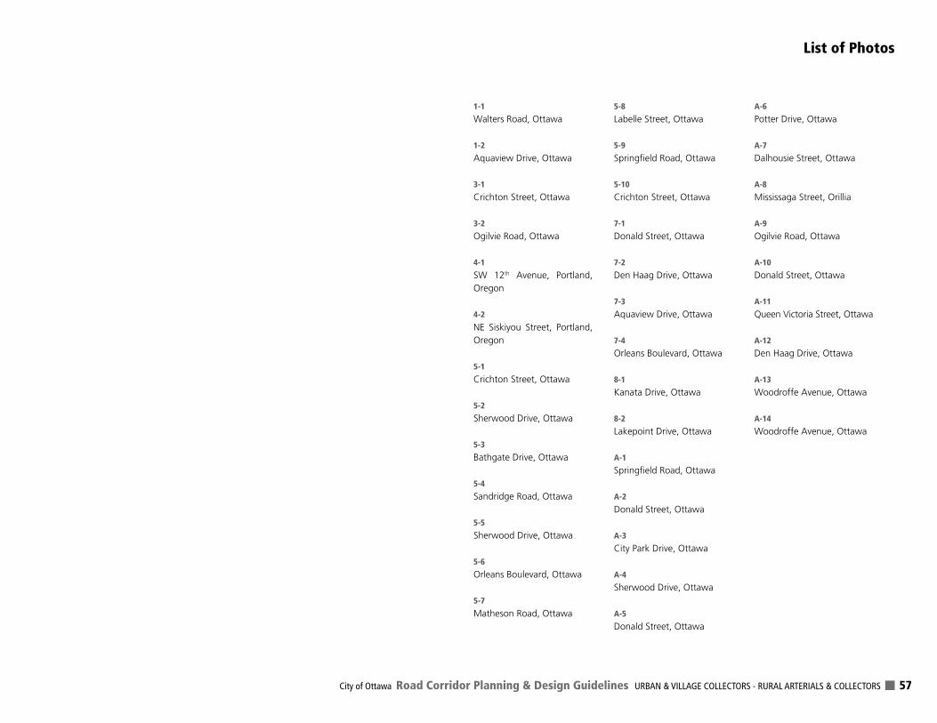
City of Ottawa Road Corridor Planning & Design Guidelines URBAN & VILLAGE COLLECTORS - RURAL ARTERIALS & COLLECTORS 57
List of Photos
1-1
Walters Road, Ottawa
1-2
Aquaview Drive, Ottawa
3-1
Crichton Street, Ottawa
3-2
Ogilvie Road, Ottawa
4-1
SW 12th Avenue, Portland, Oregon
4-2
NE Siskiyou Street, Portland, Oregon
5-1
Crichton Street, Ottawa
5-2
Sherwood Drive, Ottawa
5-3
Bathgate Drive, Ottawa
5-4
Sandridge Road, Ottawa
5-5
Sherwood Drive, Ottawa
5-6
Orleans Boulevard, Ottawa
5-7
Matheson Road, Ottawa
5-8
Labelle Street, Ottawa
5-9
Springfield Road, Ottawa
5-10
Crichton Street, Ottawa
7-1
Donald Street, Ottawa
7-2
Den Haag Drive, Ottawa
7-3
Aquaview Drive, Ottawa
7-4
Orleans Boulevard, Ottawa
8-1
Kanata Drive, Ottawa
8-2
Lakepoint Drive, Ottawa
A-1
Springfield Road, Ottawa
A-2
Donald Street, Ottawa
A-3
City Park Drive, Ottawa
A-4
Sherwood Drive, Ottawa
A-5
Donald Street, Ottawa
A-6
Potter Drive, Ottawa
A-7
Dalhousie Street, Ottawa
A-8
Mississaga Street, Orillia
A-9
Ogilvie Road, Ottawa
A-10
Donald Street, Ottawa
A-11
Queen Victoria Street, Ottawa
A-12
Den Haag Drive, Ottawa
A-13
Woodroffe Avenue, Ottawa
A-14
Woodroffe Avenue, Ottawa