RO System Design & CSMPRO program - csmfilter.com Guide CSMPRO v5.0.pdf · I. System Design...
27
RO System Design & CSMPRO program Woongjin Chemical Co. Ltd Filter Division
-
Upload
nguyentram -
Category
Documents
-
view
213 -
download
0
Transcript of RO System Design & CSMPRO program - csmfilter.com Guide CSMPRO v5.0.pdf · I. System Design...

RO System Design & CSMPRO program
Woongjin Chemical Co. Ltd Filter Division
CONTENTS I. System Design
II. CSMPRO Introduction
III. Practice CSMPRO

I. System Design

- 4 -
I. System Design Consideration of Feed Source, Application
The membrane system design depends on
Feed Source, Feed Quality, Feed/Product Flow, and Required Product Quality.
• Water Source - Well Water / Surface Water / Sea Water / Effluent Water
• Feed Quality - Pretreatment System / Feed Water Quality
• Feed / Product flow - Required Product Flow Rate / Recovery
• Required product quality - Application / Specify Water Quality Needed after RO Treatment

- 5 -
Selection of configuration and No. Passes
• Plug flow - The standard flow configuration, where the feed water is passed once through the system.
• Concentrate Recirculation - Common system used in commercial application, as well as in larger systems when the number of
elements is too small to achieve a sufficiently high system recovery with plug flow.
• Double Pass system - Combination system of two conventional RO system where permeate of the first system becomes
the feed for the second system. It is used to produce ultra pure water for semi-conductor and pharmaceutical and sea water desalination.
• Permeate Blending - The system, where some ratio of feed water or permeate of 1st pass is mixed to final product. The
smaller system can be achieved.
I. System Design

- 6 -
Membrane Type Selection
Membranes are selected by
Feed Concentration, Fouling Tendency, Required Rejection and Energy Requirements.
• Feed Concentration – Under 1,000 mg/L ; BL series
– Under 10,000 mg/L ; BN, BE
– Under 50,000 mg/L ; SHN, SHA, SHF
• Application – Softening, Concentration, 1st Pass of Seawater ; NF
– Wastewater reuse, Zero discharge ; FEn, FL, FLR
– Ultra pure water, HERO System ; HUE, UL
• Energy Requirements – Low pressure requirement ; BL, FL, UL
– Normal pressure requirement ; BE, FEn, HUE
– High pressure requirement ; BR, SHN, SHA, SHF
• Membrane Dimension
Under 4040 Size
8040 Size
1 m3/hr 2m3/hr 3 m3/hr 4 m3/hr 5 m3/hr
I. System Design

- 7 -
Determining of Average Flux
The average permeate flux should be determined by the
Feed Water Quality (SDI) as well as Feed Water Sources
Kinds of feed
water source
RO
Perme
ate
Well
Water Surface Water
Filtered Municipal Effluent
(Wastewater) Seawater
MF or UF
Pretreatment
Conven-
tional
Well
or MF
Open
intake
SDI < 1 < 3 < 3 < 5 < 3 < 5 < 3 < 5
Average Flux
(gfd) 21-25 16-20 13-17 12-16 10-14 8-12 8-12 7-10
I. System Design
* The above table is not absolutely correct but guide line.
Recommend to contact RO design expert .
- 8 -
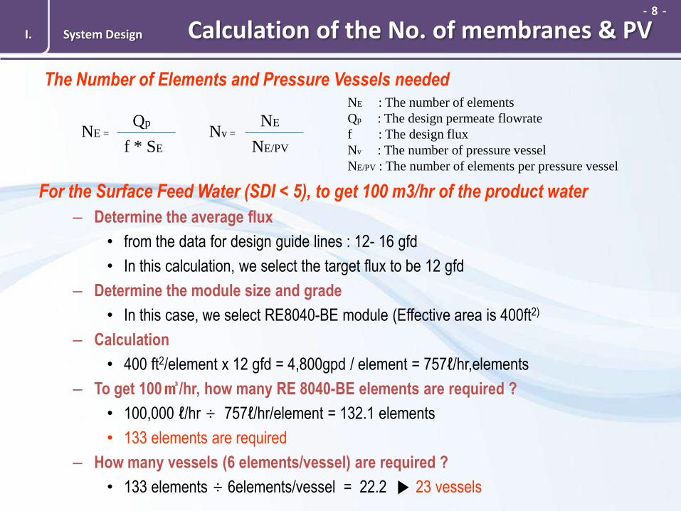
Calculation of the No. of membranes & PV
For the Surface Feed Water (SDI < 5), to get 100 m3/hr of the product water
– Determine the average flux
• from the data for design guide lines : 12- 16 gfd
• In this calculation, we select the target flux to be 12 gfd
– Determine the module size and grade
• In this case, we select RE8040-BE module (Effective area is 400ft2)
– Calculation
• 400 ft2/element x 12 gfd = 4,800gpd / element = 757ℓ/hr,elements
– To get 100㎥/hr, how many RE 8040-BE elements are required ?
• 100,000 ℓ/hr ÷ 757ℓ/hr/element = 132.1 elements
• 133 elements are required
– How many vessels (6 elements/vessel) are required ?
• 133 elements ÷ 6elements/vessel = 22.2 ▶ 23 vessels
The Number of Elements and Pressure Vessels needed
NE =
f * SE
Qp Nv =
NE/PV
NE
NE : The number of elements
Qp : The design permeate flowrate
f : The design flux
Nv : The number of pressure vessel
NE/PV : The number of elements per pressure vessel
I. System Design

- 9 -
Determining of System Array
The number of stages is a function of the planned system recovery,
the number of elements per vessel and the feed water quality.
• Designed system recovery depends on feed water source and quality in general
– For the Sea water feed : 30 - 60%
– For the Brackish water feed : 75 - 85%
– For the RO permeate feed : 85 - 95%
• Array on system recovery - Less than the 50% Recovery : one array
- Less than the 80% Recovery : two array
- over 80% Recovery : three array
For the RO permeate : System is designed to get 90% recovery with 2 array
For the Waste water : System is designed to get 75% recovery with 3 array
I. System Design
* The above table is not absolutely correct but guide line.
Recommend to contact RO design expert .

- 10 -
Consideration in Design
• Improve product quality
- Use part or all seawater elements for brackish feed water
- Use seawater elements in one or both stages of double pass system
- Recycle permeate of last stage into feed
- Use Split partial blending in double pass system
• Increase system recovery - Feed the concentrate to a second system, after specific pretreatment
- Recycle the concentrate to feed stream
• Obtain high system recovery and uniform permeate flow - Use booster pumps between stages to compensate for osmotic pressure increase
- Use permeate back pressure from first to last stage
- Use Hybrid system design with tighter membranes in the first stage than in the second stage
• Reduce the plant capacity to obtain just the required permeate quality
- Blend the permeate with feed water
I. System Design

- 11 -
Guideline for feedwater quality I. System Design
Component Unit Max. level Comments & conditions
SDI 1 5
MFI 1 4 Target <1
Oil & Grease mg/L 0.1 Target = 0
TOC mg/L 3
Synthetic organic compounds(SOC) have generally more adverse
effects on RO/NF membranes compared with natural organic
matters(NOM)
COD mg/L 10
BOD mg/L 5
Free Chlorine mg/L 0.1 Recommends removing residual free chlorine by pre-treatment prior
to membrane exposure.
TSS mg/L 1 Target=0
Ferrous iron
(Fe2+) mg/L 4 pH<6, oxygen <0.5ppm
Ferric iron
(Fe3+)
Manganese
Aluminum
mg/L 0.05 These accelerate oxidation of membrane
under existing an oxidizing component in feed water.

II. CSMPRO Introduction

- 13 -
II. CSMPRO Introduction Major Features
1. Live up to date ◆ Automatically download new files via internet before
execution of the program
◆ All data files and program files are included
2. Support to multiple language ◆ English, Korean, Chinese, Japanese are supported
◆ Able to add new languages
3. Easy Design ◆ Automatic array design ◆ Must be reviewed by an expert engineer
4. Various Output Print ◆ Save in PDF, RTF (Editable by MS Word) format ◆ Copy into a clipboard and paste on any program
which support OLE
5. Improved User interface ◆ Support a multicase design in a single file
◆ Support CPEX / OPEX
◆ Divinatory designs a layout to find what user wants
- 14 -
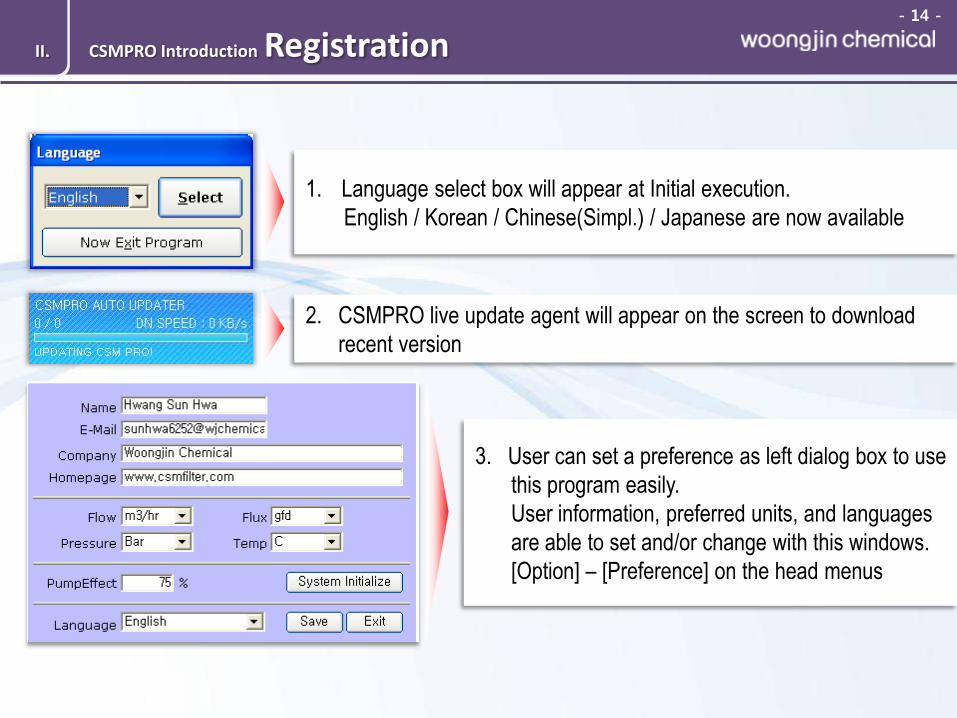
Registration
1. Language select box will appear at Initial execution.
English / Korean / Chinese(Simpl.) / Japanese are now available
2. CSMPRO live update agent will appear on the screen to download
recent version
3. User can set a preference as left dialog box to use
this program easily.
User information, preferred units, and languages
are able to set and/or change with this windows.
[Option] – [Preference] on the head menus
II. CSMPRO Introduction

- 15 -
Registration
Project Information Area
Projection Area
Unit Area
II. CSMPRO Introduction

- 16 -
System Design - Feed
1
2
3
4
5
6
7
8
1. Using this if there are multiple feed water sources
2. Select feed water source.
3. Feed water concentration.
Using TDS term or Ionic concentration
4. Feed flow for each feed source.
This is used for multiple feed waters
5. Temperature of feed water
6. Additional feed water quality.
No use for calculation but for understand
the feed water condition
7. Conductivity will be calculated
automatically, but it’s not exact.
There is no exact conversion
factor between TDS and Conductivity.
And input feed water pH.
8. Using this button to balance ion
concentration between anion and cation
II. CSMPRO Introduction

- 17 -
System Design – Scale Calculation
1
2
3
4
5
6
2. System Saturation Information pH is able to adjust with
option [pH Adjustment]
3. Execution Buttons [Calculation] button must be clicked
to activate, after all kinds of acting
4. Softening By using this option, almost Ca++,
Mg++ will changed into Na+
5. pH Adjustment By using this option, Chemical
consumption can be calculated
1. Important information to evaluate scale calculation
6. Anti-scalent Only using for chemical consumption
to evaluate operating cost
II. CSMPRO Introduction
- 18 -
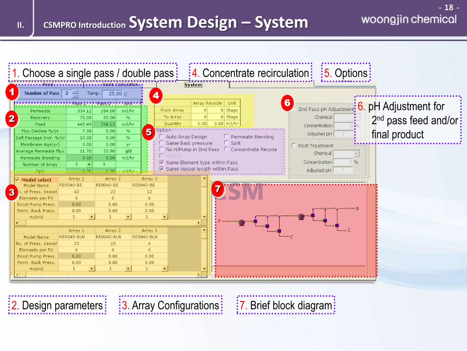
System Design – System
1
1. Choose a single pass / double pass
2
2. Design parameters
3
3. Array Configurations
4
4. Concentrate recirculation
5
5. Options
6 6. pH Adjustment for
2nd pass feed and/or
final product
7
7. Brief block diagram
II. CSMPRO Introduction

- 19 -
Diagram
Block Diagram with brief information
After click a [RESULT], the program will show a this diagram. Some information
including flow, TDS, pressure, flow diagram and recovery is demonstrated on the
results.
For more details, choose a [Result Scan] Tab.
II. CSMPRO Introduction

- 20 -
Result Scan
1 2
3
4
5
6 7
1. Overall projection data
2. Errors and Warnings
3. Toggle buttons for pass and each array data
4. Overall pass information
5. Each pass or array details
6. Ionic concentration information for
selected pass or array 7. Saturation Information
Limitation Warning
Limitation tool tip will be appeared when mouse pointer locate on a red values which
exceeded than limitation in Each pass or array details (5) and saturation information (7)
II. CSMPRO Introduction

- 21 -
Cost II. CSMPRO Introduction
1
4
3
2
5
6
7
1. Toggle buttons for pass selection
4. Capital Cost
3. System Information
7. [Calculation] button must
be clicked to see the result
after all kinds of acting
5. Operation Cost Check box should be selected to insert values.
6. Membrane Replacement
2. Unit Conversion
- 22 -
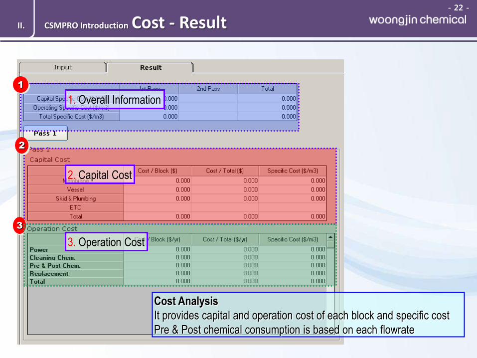
Cost - Result II. CSMPRO Introduction
1
2
3
1. Overall Information
2. Capital Cost
3. Operation Cost
Cost Analysis
It provides capital and operation cost of each block and specific cost
Pre & Post chemical consumption is based on each flowrate

- 23 -
Print Out
Several Option to use it easily
Save as PDF format
Save as RTF format – editable with MS Word
Copy and paste on any other applications
Directly print out
II. CSMPRO Introduction

III. Practice CSMPRO
- 25 -
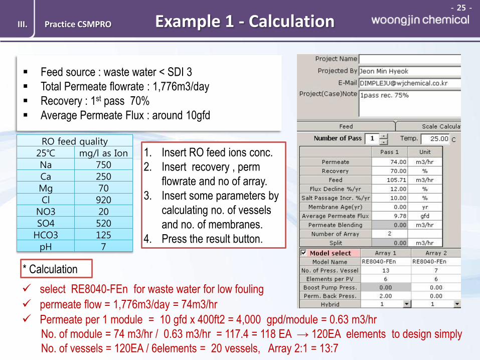
Example 1 - Calculation III. Practice CSMPRO
Feed source : waste water < SDI 3
Total Permeate flowrate : 1,776m3/day
Recovery : 1st pass 70%
Average Permeate Flux : around 10gfd
RO feed quality 25℃ mg/l as Ion Na 750
Ca 250
Mg 70
Cl 920 NO3 20
SO4 520 HCO3 125 pH 7
select RE8040-FEn for waste water for low fouling
permeate flow = 1,776m3/day = 74m3/hr
Permeate per 1 module = 10 gfd x 400ft2 = 4,000 gpd/module = 0.63 m3/hr
No. of module = 74 m3/hr / 0.63 m3/hr = 117.4 = 118 EA → 120EA elements to design simply
No. of vessels = 120EA / 6elements = 20 vessels, Array 2:1 = 13:7
1. Insert RO feed ions conc.
2. Insert recovery , perm
flowrate and no of array.
3. Insert some parameters by
calculating no. of vessels
and no. of membranes.
4. Press the result button.
* Calculation
- 26 -
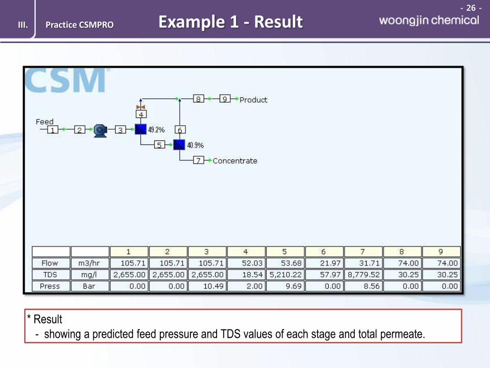
Example 1 - Result III. Practice CSMPRO
* Result
- showing a predicted feed pressure and TDS values of each stage and total permeate.


![Sony Fe2 Chassis Kd28dx40u [ET]](https://static.fdocuments.us/doc/165x107/5535bcd64a7959361a8b46c3/sony-fe2-chassis-kd28dx40u-et.jpg)