RN52 Bluetooth Audio Evaluation Kit User's...
37
2014 Microchip Technology Inc. DS50002153A RN52 Bluetooth ® Audio Evaluation Kit User’s Guide
-
Upload
trinhduong -
Category
Documents
-
view
219 -
download
0
Transcript of RN52 Bluetooth Audio Evaluation Kit User's...
2014 Microchip Technology Inc. DS50002153A
RN52 Bluetooth® AudioEvaluation Kit User’s Guide

DS50002153A-page 2 2014 Microchip Technology Inc.
Information contained in this publication regarding deviceapplications and the like is provided only for your convenienceand may be superseded by updates. It is your responsibility toensure that your application meets with your specifications.MICROCHIP MAKES NO REPRESENTATIONS ORWARRANTIES OF ANY KIND WHETHER EXPRESS ORIMPLIED, WRITTEN OR ORAL, STATUTORY OROTHERWISE, RELATED TO THE INFORMATION,INCLUDING BUT NOT LIMITED TO ITS CONDITION,QUALITY, PERFORMANCE, MERCHANTABILITY ORFITNESS FOR PURPOSE. Microchip disclaims all liabilityarising from this information and its use. Use of Microchipdevices in life support and/or safety applications is entirely atthe buyer’s risk, and the buyer agrees to defend, indemnify andhold harmless Microchip from any and all damages, claims,suits, or expenses resulting from such use. No licenses areconveyed, implicitly or otherwise, under any Microchipintellectual property rights.
Note the following details of the code protection feature on Microchip devices:
• Microchip products meet the specification contained in their particular Microchip Data Sheet.
• Microchip believes that its family of products is one of the most secure families of its kind on the market today, when used in the intended manner and under normal conditions.
• There are dishonest and possibly illegal methods used to breach the code protection feature. All of these methods, to our knowledge, require using the Microchip products in a manner outside the operating specifications contained in Microchip’s Data Sheets. Most likely, the person doing so is engaged in theft of intellectual property.
• Microchip is willing to work with the customer who is concerned about the integrity of their code.
• Neither Microchip nor any other semiconductor manufacturer can guarantee the security of their code. Code protection does not mean that we are guaranteeing the product as “unbreakable.”
Code protection is constantly evolving. We at Microchip are committed to continuously improving the code protection features of ourproducts. Attempts to break Microchip’s code protection feature may be a violation of the Digital Millennium Copyright Act. If such actsallow unauthorized access to your software or other copyrighted work, you may have a right to sue for relief under that Act.
Microchip received ISO/TS-16949:2009 certification for its worldwide headquarters, design and wafer fabrication facilities in Chandler and Tempe, Arizona; Gresham, Oregon and design centers in California and India. The Company’s quality system processes and procedures are for its PIC® MCUs and dsPIC® DSCs, KEELOQ® code hopping devices, Serial EEPROMs, microperipherals, nonvolatile memory and analog products. In addition, Microchip’s quality system for the design and manufacture of development systems is ISO 9001:2000 certified.
QUALITYMANAGEMENTSYSTEMCERTIFIEDBYDNV
== ISO/TS16949==
Trademarks
The Microchip name and logo, the Microchip logo, dsPIC, FlashFlex, KEELOQ, KEELOQ logo, MPLAB, PIC, PICmicro, PICSTART, PIC32 logo, rfPIC, SST, SST Logo, SuperFlash and UNI/O are registered trademarks of Microchip Technology Incorporated in the U.S.A. and other countries.
FilterLab, Hampshire, HI-TECH C, Linear Active Thermistor, MTP, SEEVAL and The Embedded Control Solutions Company are registered trademarks of Microchip Technology Incorporated in the U.S.A.
Silicon Storage Technology is a registered trademark of Microchip Technology Inc. in other countries.
Analog-for-the-Digital Age, Application Maestro, BodyCom, chipKIT, chipKIT logo, CodeGuard, dsPICDEM, dsPICDEM.net, dsPICworks, dsSPEAK, ECAN, ECONOMONITOR, FanSense, HI-TIDE, In-Circuit Serial Programming, ICSP, Mindi, MiWi, MPASM, MPF, MPLAB Certified logo, MPLIB, MPLINK, mTouch, Omniscient Code Generation, PICC, PICC-18, PICDEM, PICDEM.net, PICkit, PICtail, REAL ICE, rfLAB, Select Mode, SQI, Serial Quad I/O, Total Endurance, TSHARC, UniWinDriver, WiperLock, ZENA and Z-Scale are trademarks of Microchip Technology Incorporated in the U.S.A. and other countries.
SQTP is a service mark of Microchip Technology Incorporated in the U.S.A.
GestIC and ULPP are registered trademarks of Microchip Technology Germany II GmbH & Co. KG, a subsidiary of Microchip Technology Inc., in other countries.
All other trademarks mentioned herein are property of their respective companies.
© 2014, Microchip Technology Incorporated, Printed in the U.S.A., All Rights Reserved.
Printed on recycled paper.
ISBN: 978-1-63276-021-0
RN52 Bluetooth Audio Evaluation Kit User’s Guide
Object of Declaration: RN52 Bluetooth Audio Evaluation Kit
2014 Microchip Technology Inc. DS50002153A-page 3

RN52 Bluetooth Audio Evaluation Kit User’s Guide
NOTES:
2014 Microchip Technology Inc. DS50002153A-page 4

RN52 BLUETOOTH AUDIOEVALUATION KIT USER’S GUIDE
Table of Contents
Preface ........................................................................................................................... 7
Chapter 1. Overview1.1 Introduction ................................................................................................... 131.2 RN52 Evaluation Kit Features ...................................................................... 131.3 RN52 Evaluation Kit Contents and Part Details ........................................... 141.4 RN-52-EK Evaluation Board ......................................................................... 151.5 RN52 Evaluation Kit Related Information Contents ..................................... 17
Chapter 2. Getting Started2.1 Introduction ................................................................................................... 192.2 Hardware Requirements .............................................................................. 192.3 Power Up the Board ..................................................................................... 202.4 Using the Evaluation Kit ............................................................................... 20
Chapter 3. Application Demonstrations3.1 Audio Demonstration .................................................................................... 273.2 HSP/HFP Demonstration ............................................................................. 28
Appendix A. RN52 Audio Evaluation Kits SchematicsA.1 Introduction .................................................................................................. 29A.2 RN52 Evaluation Kits Schematic ................................................................. 29A.3 RN52 Evaluation Kits PCB Layout and Assemble Drawings ....................... 31A.4 RN52 Evaluation Kits Bill of Materials .......................................................... 34A.5 RN52 Evaluation Kits Physical Dimensions ................................................. 35
Worldwide Sales and Service .................................................................................... 37
2014 Microchip Technology Inc. DS50002153A-page 5
RN52 Bluetooth Audio Evaluation Kit User’s Guide
DS50002153A-page 6 2014 Microchip Technology Inc.
NOTES:
RN52 BLUETOOTH AUDIOEVALUATION KIT USER’S GUIDE
Preface
INTRODUCTION
This chapter contains general information that will be useful to know before using the Product Name. Items discussed in this chapter include:
• Document Layout
• Conventions Used in this Guide
• Warranty Registration
• Recommended Reading
• The Microchip Web Site
• Development Systems Customer Change Notification Service
• Customer Support
• Document Revision History
DOCUMENT LAYOUT
This user’s guide describes how to use the RN52 Bluetooth Audio Evaluation Kit. The document is organized as follows:
• Chapter 1. “Overview” – This chapter introduces the RN52 Bluetooth Audio Evaluation Kit and provides an overview of various features.
• Chapter 2. “Getting Started” – This chapter describes the hardware components and setup of the RN52 Bluetooth Audio Evaluation Kit.
• Chapter 3. “Application Demonstrations” – This chapter describes the application demonstrations of the RN52 Bluetooth Audio Evaluation Kit.
• Appendix A. “RN52 Audio Evaluation Kits Schematics” – This appendix includes a schematic of the RN-52-EK Evaluation Board, and the Bill of Materials.
NOTICE TO CUSTOMERS
All documentation becomes dated, and this manual is no exception. Microchip tools and documentation are constantly evolving to meet customer needs, so some actual dialogs and/or tool descriptions may differ from those in this document. Please refer to our web site (www.microchip.com) to obtain the latest documentation available.
Documents are identified with a “DS” number. This number is located on the bottom of each page, in front of the page number. The numbering convention for the DS number is “DSXXXXXA”, where “XXXXX” is the document number and “A” is the revision level of the document.
For the most up-to-date information on development tools, see the MPLAB® IDE on-line help. Select the Help menu, and then Topics to open a list of available on-line help files.
2014 Microchip Technology Inc. DS50002153A-page 7
RN52 Bluetooth Audio Evaluation Kit User’s Guide
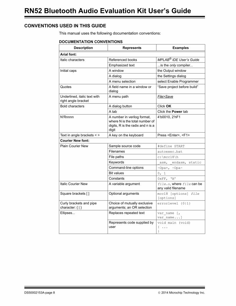
CONVENTIONS USED IN THIS GUIDE
This manual uses the following documentation conventions:
DOCUMENTATION CONVENTIONS
Description Represents Examples
Arial font:
Italic characters Referenced books MPLAB® IDE User’s Guide
Emphasized text ...is the only compiler...
Initial caps A window the Output window
A dialog the Settings dialog
A menu selection select Enable Programmer
Quotes A field name in a window or dialog
“Save project before build”
Underlined, italic text with right angle bracket
A menu path File>Save
Bold characters A dialog button Click OK
A tab Click the Power tab
N‘Rnnnn A number in verilog format, where N is the total number of digits, R is the radix and n is a digit
4‘b0010, 2‘hF1
Text in angle brackets < > A key on the keyboard Press <Enter>, <F1>
Courier New font:
Plain Courier New Sample source code #define START
Filenames autoexec.bat
File paths c:\mcc18\h
Keywords _asm, _endasm, static
Command-line options -Opa+, -Opa-
Bit values 0, 1
Constants 0xFF, ‘A’
Italic Courier New A variable argument file.o, where file can be any valid filename
Square brackets [ ] Optional arguments mcc18 [options] file [options]
Curly brackets and pipe character: |
Choice of mutually exclusive arguments; an OR selection
errorlevel 0|1
Ellipses... Replaces repeated text var_name [, var_name...]
Represents code supplied by user
void main (void) ...
DS50002153A-page 8 2014 Microchip Technology Inc.
Preface
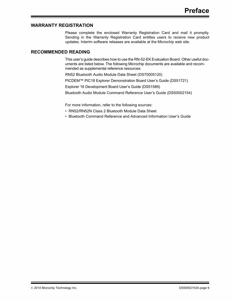
WARRANTY REGISTRATION
Please complete the enclosed Warranty Registration Card and mail it promptly.Sending in the Warranty Registration Card entitles users to receive new productupdates. Interim software releases are available at the Microchip web site.
RECOMMENDED READING
This user’s guide describes how to use the RN-52-EK Evaluation Board. Other useful doc-uments are listed below. The following Microchip documents are available and recom-mended as supplemental reference resources:
RN52 Bluetooth Audio Module Data Sheet (DS70005120)
PICDEM™ PIC18 Explorer Demonstration Board User’s Guide (DS51721)
Explorer 16 Development Board User’s Guide (DS51589)
Bluetooth Audio Module Command Reference User’s Guide (DS50002154)
For more information, refer to the following sources:
• RN52/RN52N Class 2 Bluetooth Module Data Sheet
• Bluetooth Command Reference and Advanced Information User’s Guide
2014 Microchip Technology Inc. DS50002153A-page 9

RN52 Bluetooth Audio Evaluation Kit User’s Guide
THE MICROCHIP WEB SITE
Microchip provides online support via our web site at http://www.microchip.com. This web site is used as a means to make files and information easily available to customers. Accessible by using your favorite Internet browser, the web site contains the following information:
• Product Support – Data sheets and errata, application notes and sample programs, design resources, user’s guides and hardware support documents, latest software releases and archived software
• General Technical Support – Frequently Asked Questions (FAQs), technical support requests, online discussion groups, Microchip consultant program member listing
• Business of Microchip – Product selector and ordering guides, latest Microchip press releases, listing of seminars and events, listings of Microchip sales offices, distributors and factory representatives
DEVELOPMENT SYSTEMS CUSTOMER CHANGE NOTIFICATION SERVICE
Microchip’s customer notification service helps keep customers current on Microchip products. Subscribers will receive e-mail notification whenever there are changes, updates, revisions or errata related to a specified product family or development tool of interest.
To register, access the Microchip web site at http://www.microchip.com, click on Cus-tomer Change Notification and follow the registration instructions.
The Development Systems product group categories are:
• Compilers – The latest information on Microchip C compilers and other language tools. These include the MPLAB® C compiler; MPASM™ and MPLAB 16-bit assemblers; MPLINK™ and MPLAB 16-bit object linkers; and MPLIB™ and MPLAB 16-bit object librarians.
• Emulators – The latest information on the Microchip MPLAB REAL ICE™ in-circuit emulator.
• In-Circuit Debuggers – The latest information on the Microchip in-circuit debugger, MPLAB ICD 3.
• MPLAB IDE – The latest information on Microchip MPLAB IDE, the Windows® Integrated Development Environment for development systems tools. This list is focused on the MPLAB IDE, MPLAB SIM simulator, MPLAB IDE Project Manager and general editing and debugging features.
• Programmers – The latest information on Microchip programmers. These include the MPLAB PM3 device programmer and the PICkit™ 3 development programmers.
DS50002153A-page 10 2014 Microchip Technology Inc.
Preface
CUSTOMER SUPPORT
Users of Microchip products can receive assistance through several channels:
• Distributor or Representative
• Local Sales Office
• Field Application Engineer (FAE)
• Technical Support
Customers should contact their distributor, representative or Field Application Engineer (FAE) for support. Local sales offices are also available to help customers. A listing of sales offices and locations is included in the back of this document.
Technical support is available through the web site at: http://support.microchip.com
DOCUMENT REVISION HISTORY
Revision A (March 2014)
This is the initial released version of this document.
2014 Microchip Technology Inc. DS50002153A-page 11
RN52 Bluetooth Audio Evaluation Kit User’s Guide
NOTES:
DS50002153A-page 12 2014 Microchip Technology Inc.
RN52 BLUETOOTH AUDIOEVALUATION KIT USER’S GUIDE
Chapter 1. Overview
1.1 INTRODUCTION
This user’s guide describes the hardware and software setup for the RN52 Bluetooth® Audio Evaluation Kit. This kit contains the hardware needed to evaluate the RN52 Bluetooth audio module. The RN52 module is mounted to an evaluation board that demonstrates the module’s key features. The evaluation board contains:
• Dual-channel audio output and input
• Easy access to GPIO pins
• Built-in amplifier for stereo audio output
• 6 push buttons to control audio playback
• Status LEDs
• Connections for the programmer and UART interfaces
The RN52 supports the following Bluetooth profiles:
• A2DP stereo audio (Sink mode with support for Sub-Band Coding (SBC), Advanced Audio Coding (AAC) and aptX® codecs
• AVRCP media player remote control
• HFP/HSP for accepting a phone call with 3-way calling and caller-ID support
• Support for Clear Voice Capture® (cVc) voice enhancement through HFP/HSP
• SPP (allows the module to receive serial data over the UART)
• iAP profile discovery for iOS devices
The evaluation kit can be used to configure and program the Bluetooth module using the command interface, create connections, and transfer data. The command interface is made up of simple ASCII commands. For more details, refer to the “RN52 Bluetooth Audio Module Data Sheet”, “Bluetooth Audio Module Command Reference User’s Guide”, and “Bluetooth Command Reference and Advanced Information User’s Guide”.
For data sheet and other details related to RN52 module, refer to the Microchip web site at http://www.microchip.com.
This chapter discusses the following topics:
• RN52 Evaluation Kit Features
• RN52 Evaluation Kit Contents and Part Details
• RN-52-EK Evaluation Board
• RN52 Evaluation Kit Related Information Contents
1.2 RN52 EVALUATION KIT FEATURES
1.2.1 RN52 Evaluation Board Features
The RN52 Evaluation Board has the following features:
• Fully qualified Bluetooth version 3.0 module, fully compatible with Bluetooth ver-sion 2.1 + Enhanced Data Rate (EDR), 1.2, and 1.1
• Backwards-compatibility with Bluetooth version 2.0, 1.2, and 1.1
• Software configurable through commands over UART console interface
2014 Microchip Technology Inc. DS50002153A-page 13

RN52 Bluetooth Audio Evaluation Kit User’s Guide
• Dedicated GPIO pins enable MCUs to access control and status functions effi-ciently
• Embedded RN-52 module with postage-stamp size form factor of 13.5 x 26.0 x 2.7 mm
• Embedded Bluetooth stack profiles: A2DP, AVRCP, HFP/HSP, and SPP
• Dual-channel, differential audio input and output for highest quality audio
• Supports iAP profile to discover iOS devices and apps (requires a special firm-ware build)
• Integrated amplifier for driving 16 Ω speakers
• UART (SPP) data connection interfaces
• External audio CODECs supported via S/PDIF and I2S interface
• Castellated SMT pads for easy and reliable PCB mounting
• Environmentally friendly, RoHS compliant
• Certifications: FCC, IC, and CE
• Bluetooth SIG certified
1.3 RN52 EVALUATION KIT CONTENTS AND PART DETAILS
The evaluation kit includes the hardware required to connect the evaluation board to the host computer. See Table 1-1. To evaluate the module on the evaluation board, the user needs a computer with a USB port running the Microsoft Windows or Mac OS-X operating system.
Depending on the development kit ordered, the package contains the following:
• RN-52-EK Board - Contains the Bluetooth module and connectors. Supports Standard application firmware (A2DP/AVRCP/SPP) master and slave
• Mini-USB cable - Links user’s computer to the evaluation board
• Stereo mini-speakers - Rechargeable battery-powered speakers
Table 1-1 lists the part number of RN-52-EK Evaluation Kit.
TABLE 1-1: RN52 EVALUATION KIT PART DETAILS
Note: Prior to the evaluation, install the FTDI driver for the USB cable. If the driv-ers are not automatically installed, download and install the FTDI drivers from the Microchip web site at http://ww1.microchip.com/down-loads/en/DeviceDoc/FTDI-Drivers.zip for FTDI Chipset Drivers.
Description Part Number
RN52 Evaluation board RN-52-EK
Mini-USB cable —
Duo Rechargeable Mini-Speaker Set (includes Universal 3.5mm Audio Plug and USB cable)
—
Hands Free Clip on Mini Lapel Microphone
—
DS50002153A-page 14 2014 Microchip Technology Inc.
Overview
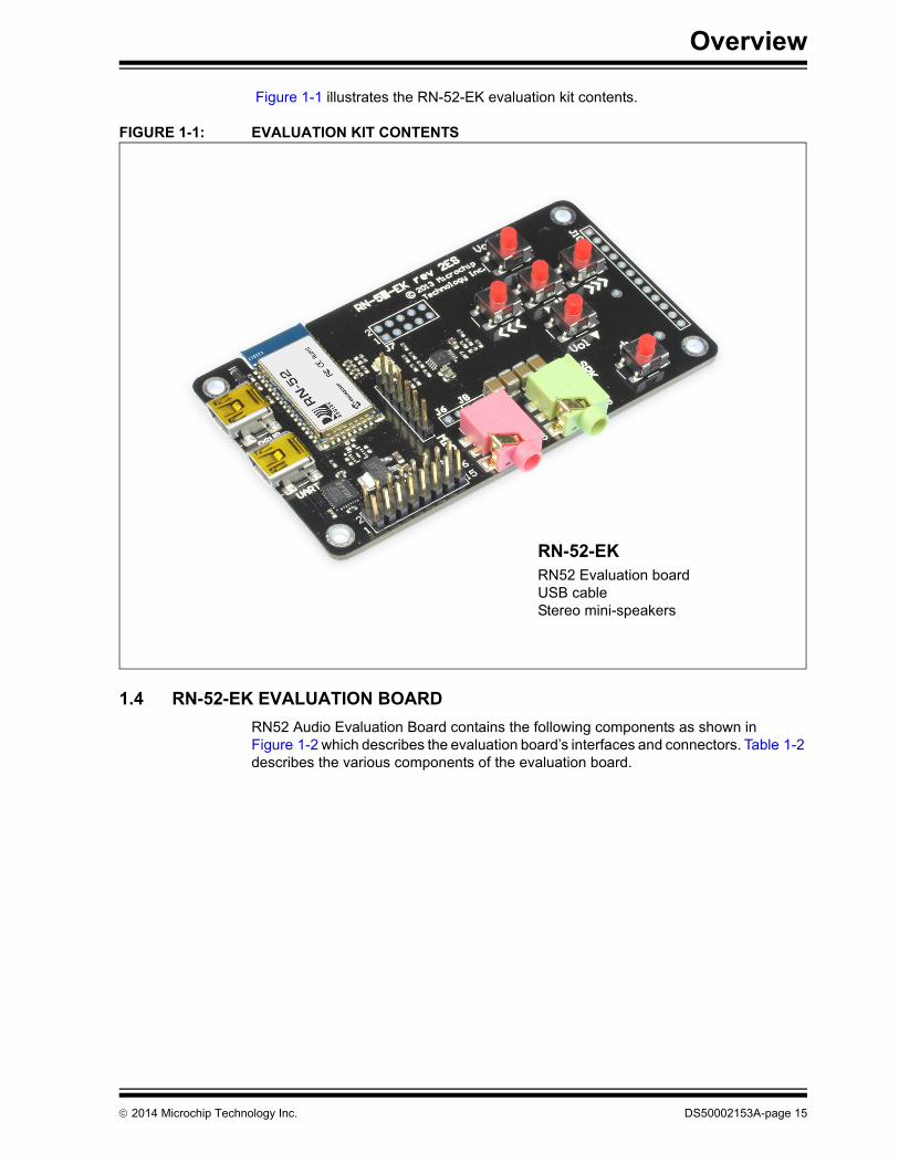
Figure 1-1 illustrates the RN-52-EK evaluation kit contents.
FIGURE 1-1: EVALUATION KIT CONTENTS
1.4 RN-52-EK EVALUATION BOARD
RN52 Audio Evaluation Board contains the following components as shown in Figure 1-2 which describes the evaluation board’s interfaces and connectors. Table 1-2 describes the various components of the evaluation board.
RN-52-EKRN52 Evaluation board USB cable Stereo mini-speakers
2014 Microchip Technology Inc. DS50002153A-page 15
RN52 Bluetooth Audio Evaluation Kit User’s Guide
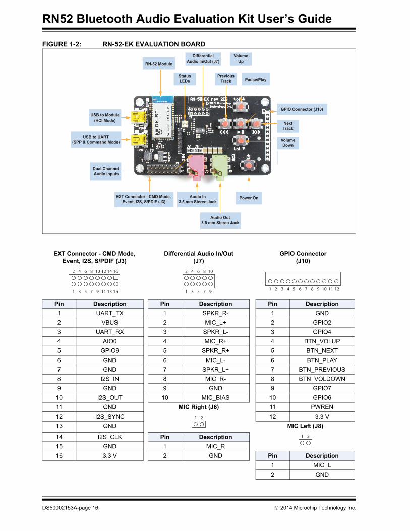
FIGURE 1-2: RN-52-EK EVALUATION BOARD
EXT Connector - CMD Mode, Event, I2S, S/PDIF (J3)
Differential Audio In/Out (J7)
GPIO Connector (J10)
Pin Description Pin Description Pin Description
1 UART_TX 1 SPKR_R- 1 GND
2 VBUS 2 MIC_L+ 2 GPIO2
3 UART_RX 3 SPKR_L- 3 GPIO4
4 AIO0 4 MIC_R+ 4 BTN_VOLUP
5 GPIO9 5 SPKR_R+ 5 BTN_NEXT
6 GND 6 MIC_L- 6 BTN_PLAY
7 GND 7 SPKR_L+ 7 BTN_PREVIOUS
8 I2S_IN 8 MIC_R- 8 BTN_VOLDOWN
9 GND 9 GND 9 GPIO7
10 I2S_OUT 10 MIC_BIAS 10 GPIO6
11 GND MIC Right (J6) 11 PWREN
12 I2S_SYNC 12 3.3 V
13 GND MIC Left (J8)
14 I2S_CLK Pin Description
15 GND 1 MIC_R
16 3.3 V 2 GND Pin Description
1 MIC_L
2 GND
EXT Connector - CMD Mode, Event, I2S, S/PDIF (J3)
USB to Module(HCI Mode)
USB to UART(SPP & Command Mode)
Dual Channel Audio Inputs
Audio In3.5 mm Stereo Jack
Audio Out3.5 mm Stereo Jack
StatusLEDs
DifferentialAudio In/Out (J7)
VolumeUp
PreviousTrack Pause/Play
VolumeDown
NextTrack
Power On
GPIO Connector (J10)
RN-52 Module
161412
151311
2 10864
1 9753
2 10864
1 9753 12112 108641 9753
1 2
1 2
DS50002153A-page 16 2014 Microchip Technology Inc.
Overview
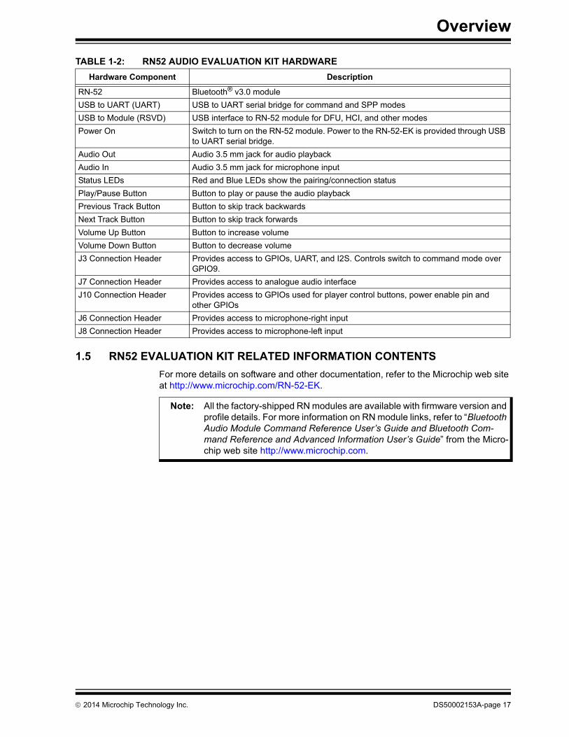
TABLE 1-2: RN52 AUDIO EVALUATION KIT HARDWARE
1.5 RN52 EVALUATION KIT RELATED INFORMATION CONTENTS
For more details on software and other documentation, refer to the Microchip web site at http://www.microchip.com/RN-52-EK.
Hardware Component Description
RN-52 Bluetooth® v3.0 module
USB to UART (UART) USB to UART serial bridge for command and SPP modes
USB to Module (RSVD) USB interface to RN-52 module for DFU, HCI, and other modes
Power On Switch to turn on the RN-52 module. Power to the RN-52-EK is provided through USB to UART serial bridge.
Audio Out Audio 3.5 mm jack for audio playback
Audio In Audio 3.5 mm jack for microphone input
Status LEDs Red and Blue LEDs show the pairing/connection status
Play/Pause Button Button to play or pause the audio playback
Previous Track Button Button to skip track backwards
Next Track Button Button to skip track forwards
Volume Up Button Button to increase volume
Volume Down Button Button to decrease volume
J3 Connection Header Provides access to GPIOs, UART, and I2S. Controls switch to command mode over GPIO9.
J7 Connection Header Provides access to analogue audio interface
J10 Connection Header Provides access to GPIOs used for player control buttons, power enable pin and other GPIOs
J6 Connection Header Provides access to microphone-right input
J8 Connection Header Provides access to microphone-left input
Note: All the factory-shipped RN modules are available with firmware version and profile details. For more information on RN module links, refer to “Bluetooth Audio Module Command Reference User’s Guide and Bluetooth Com-mand Reference and Advanced Information User’s Guide” from the Micro-chip web site http://www.microchip.com.
2014 Microchip Technology Inc. DS50002153A-page 17

RN52 Bluetooth Audio Evaluation Kit User’s Guide
NOTES:
DS50002153A-page 18 2014 Microchip Technology Inc.

RN52 BLUETOOTH AUDIOEVALUATION KIT USER’S GUIDE
Chapter 2. Getting Started
2.1 INTRODUCTION
This chapter describes how the RN52 Audio Evaluation Kit board works using the ASCII command set. Certain hardware and software/utilities are essential to support the evaluation/development of demo applications. This chapter discussess the follow-ing topics:
• Hardware Requirements
• Software/Utility Requirements
• Module Configuration
2.2 HARDWARE REQUIREMENTS
Along with an USB cable RN-52-EK boards are required for evaluation hardware setup and to run the firmware/demo appplications.
2.2.1 Hardware Setup
To setup the evaluation hardware, perform the following steps:
1. Connect the mini-USB cable to your computer’s USB port and to the evaluation board’s UART (USB-UART bridge) connector. This connection provides power to the board, and provides a virtual serial data port connection to the command console and in SPP mode.
2. Prior to the evaluation, install the FTDI driver for the USB cable.
3. Note down the assigned computer COM port to which the RN-52-EK is attached through the cable connected.
4. Connect the portable mini-speaker 3.5 mm to the stereo audio out connector (J9).
Figure 2-1 shows the completed hardware setup for the evaluation board.
Note: If the drivers are not automatically installed, download and install the FTDI drivers from the Microchip web site at http://ww1.microchip.com/down-loads/en/DeviceDoc/FTDI-Drivers.zip for FTDI Chipset Drivers.
2014 Microchip Technology Inc. DS50002153A-page 19

RN52 Bluetooth Audio Evaluation Kit User’s Guide
FIGURE 2-1: CONNECTED HARDWARE SETUP
2.3 POWER UP THE BOARD
To power-up the board, connect the board to a power source via USB, and then press and hold the evaluation board’s power-on button until the speakers issue a two-tone alert. The RN52 evaluation board’s status LEDs give user a visual confirmation that the board is powered up and operating. See Table 2-1.
2.4 USING THE EVALUATION KIT
This section of the user’s guide assumes that users have a basic working knowledge of Bluetooth operation and communications. To configure the Bluetooth devices, a Bluetooth-enabled PC (either built-in or using a USB Bluetooth dongle) is required. Only one device can be configured at a time. Once programmed and configured, device settings are saved (independent of power down) until they are explicitly changed or the factory defaults are restored.
The RN52 uses simple ASCII commands sent over UART interface to: set commands to configure the Bluetooth module and get commands to echo the current configuration. Configuration settings modified with the set command do not take effect until the mod-ule has been rebooted, even though the get command may show otherwise.
TABLE 2-1: RN52 AUDIO EVALUATION BOARD STATUS LEDS
LED Status Description
Blue and red Flashing The RN52 module is discoverable
Blue only Flashing The module is connectable
Red only Flashing The module is connected
Note: For detailed information on the ASCII comands used to configure the Blue-tooth module, refer to the “Bluetooth Command Reference and Advanced Information User’s Guide”.
DS50002153A-page 20 2014 Microchip Technology Inc.
Getting Started
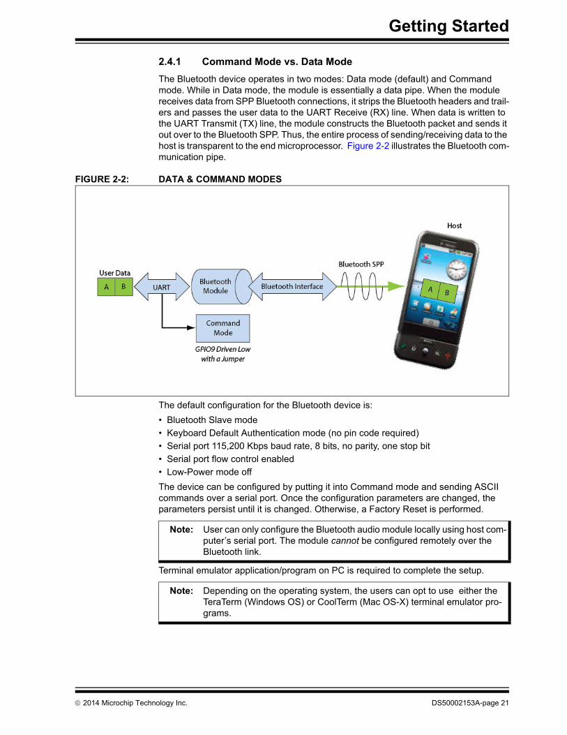
2.4.1 Command Mode vs. Data Mode
The Bluetooth device operates in two modes: Data mode (default) and Command mode. While in Data mode, the module is essentially a data pipe. When the module receives data from SPP Bluetooth connections, it strips the Bluetooth headers and trail-ers and passes the user data to the UART Receive (RX) line. When data is written to the UART Transmit (TX) line, the module constructs the Bluetooth packet and sends it out over to the Bluetooth SPP. Thus, the entire process of sending/receiving data to the host is transparent to the end microprocessor. Figure 2-2 illustrates the Bluetooth com-munication pipe.
FIGURE 2-2: DATA & COMMAND MODES
The default configuration for the Bluetooth device is:
• Bluetooth Slave mode
• Keyboard Default Authentication mode (no pin code required)
• Serial port 115,200 Kbps baud rate, 8 bits, no parity, one stop bit
• Serial port flow control enabled
• Low-Power mode off
The device can be configured by putting it into Command mode and sending ASCII commands over a serial port. Once the configuration parameters are changed, the parameters persist until it is changed. Otherwise, a Factory Reset is performed.
Terminal emulator application/program on PC is required to complete the setup.
Note: User can only configure the Bluetooth audio module locally using host com-puter’s serial port. The module cannot be configured remotely over the Bluetooth link.
Note: Depending on the operating system, the users can opt to use either the TeraTerm (Windows OS) or CoolTerm (Mac OS-X) terminal emulator pro-grams.
2014 Microchip Technology Inc. DS50002153A-page 21

RN52 Bluetooth Audio Evaluation Kit User’s Guide
2.4.2 Configure the Module Using the UART
Setup the RN-52-EK hardware as described in Section 2.2.1 “Hardware Setup”. With the Bluetooth device connected and powered on, run a terminal emulator and open the COM port to which the RN-52-EK link cable is connected. Configure the virtual COM port connected to the RN-52-EK USB interface with the default settings (115,200 Kbps baud, no parity, 8 bits, 1 stop bit).The terminal emulator’s communication settings should be the default serial port settings.
Command mode can be switched through the UART interface via the USB connector at any time when the device does NOT have a Bluetooth connection, as well as under certain conditions. If the device is in configuration mode and a connection occurs, the device exits configuration mode and data passes back and forth from the remote device.
2.4.3 Enter Command Mode
The RN52 module enters Command mode when GPIO09 goes low. The RN52 module leaves command mode and enters data mode when GPIO09 goes high. With the RN-52-EK evaluation board, use a jumper to switch between command and data modes.
Launch a terminal emulator and specify the adapter’s default settings. Figure 2-3 shows the serial port settings dialog box for TeraTerm (open this dialog box by choosing Setup > Serial Port).
FIGURE 2-3: SERIAL PORT SETTINGS IN TERATERM
To place the module on the RN-52-EK evaluation board into Command mode, connect a jumper to header pins 5 (GPIO9) and 6 (GND) on J3. Refer to Figure 2-4 and its Con-nector-Pin details. After entering Command mode, the module sends CMD to the UART as acknowledgement.
Note: Local configuration can be used at any time when the device does NOT have a Bluetooth connection, as well as under certain conditions. If the device is in Configuration mode and a connection occurs, the device exits Configuration mode and data passes back and forth from the remote device.
DS50002153A-page 22 2014 Microchip Technology Inc.

Getting Started
FIGURE 2-4: GPIO9 LOCATION
Type the following commands into the Tera Term console:
+ // Turn on local echo
v // Display the firmware version
d // Display the current settings
q // Show the connection status
To switch into Data mode, remove the jumper from header pins 5 (GPIO9) and 6 (GND) on J3. When leaving Command mode, the module sends END to the UART. Figure 2-5 shows the Tera Term console after performing these actions.
FIGURE 2-5: COMMAND MODE ACTIONS IN A SERIALTERMINAL EMULATOR
GPIO9
2014 Microchip Technology Inc. DS50002153A-page 23

RN52 Bluetooth Audio Evaluation Kit User’s Guide
2.4.4 Making a Bluetooth Connection
By default, the Bluetooth adapter acts as a slave and the PC is the master. Connect to the Bluetooth adapter using the computer’s Bluetooth device manager, which varies depending on the operating system. Regardless of the operating system, the process is the same: Discovery, Pairing, and Connecting.
2.4.4.1 DISCOVERY
When the RN-52-EK is turned on, the Blue and Red LED should blink and the adapter should be discoverable. Open the host PC’s Bluetooth device manager and choose to add a new device. The Bluetooth device manager’s icon is located at the bottom right corner on the host’s computer screen in the taskbar for Windows; and at the upper right corner for Mac OS-X. The Bluetooth device manager displays a list of discoverable Bluetooth devices. The board displays as RN52-XXXX, where XXXX is the last 4-digits of the module’s MAC address.
2.4.4.2 PAIRING
The module supports the following pairing methods:
• Legacy Pairing using PIN code
• Secure Simple Pairing (SSP)
- Just Works
- Numeric Comparison using Yes/No Keyboard IO
The RN-52 module can be configured through command console to use either of the above pairing methods.
To pair with the module, double click its name in the Bluetooth device scan list. The default authentication mode is Just Works which requires no user interaction. The link key is generated, stored and a connection gets established. For subsequent connec-tions, the stored link keys are compared and the connection is established. The mod-ule’s firmware automatically stores up to 8 pairings from remote hosts in a first in, first out fashion.
If the remote Bluetooth device does not require authentication, a connection can occur without the pairing process. However, the Bluetooth specification requires that if either device involved in the pairing process requires authentication, the other device must participate to ensure a secure link. Microchip modules default to Just Works mode and do not require authentication.
In numeric comparison using yes/no keyboard IO mode, the user is shown a 6-digit number on both the module console and the pairing device display. The user has to ver-ify that the numbers match or do not match on both devices by entering yes or no. A command is provided to enter yes or no on the module command console.
In legacy pairing mode, the pairing device requests a 4-digit fixed PIN for authentica-tion. In this case, use the module’s default PIN code, 1234, as the pass key. After enter-ing the PIN code, the Bluetooth devices are compared. If a match is found, a link key is generated and stored. Usually, but not always, the remote device stores the link key. For subsequent connections, the devices compare link keys. If correct, there is no need to re-enter the PIN code. The PIN code can be set as desired using command console.
To remove the stored link key on the remote device, you typically “unpair” or remove the device from the Bluetooth manager. The pairing information can be reset by exe-cuting the reset Paired Device List (PDL) on the command console. You can change the PIN code to remove the link key on the Bluetooth adapter, forcing a new pin code exchange to occur upon subsequent connection attempts.
DS50002153A-page 24 2014 Microchip Technology Inc.

Getting Started
Figure 2-6 shows examples of Bluetooth devices discovered list and pair/connect inter-faces.
FIGURE 2-6: PAIRING/CONNECTING WITH THE BLUETOOTH® ADAPTER
2.4.4.3 CONNECTING
If the pairing with the device is successful, the module can connect to the device. Click connect using the pair/connect interface to establish a connection.
Once connected, the module enables Advanced Audio Distribution Profile (A2DP) for audio playback and Audio Video Remote Control Profile (AVRCP) for player control.
Additionally, a Serial Port Profile (SPP) link can be established by opening the virtual COM port available on the RN52 module from a PC over its Bluetooth device.
When connecting to a PC using SPP, after the Bluetooth device manager completes pairing/connecting, it issues a message that the Bluetooth device is installed on COM port X where the specific COM port is unique to the user’s computer. After connecting successfully, the data can be transmitted and received on the Bluetooth COM port link in Data mode.
In some cases, the Bluetooth device manager creates two COM ports. In this situation, use the incoming port to wait for the module to initiate a connection. Open the outgoing port to establish a connection to the module.
Note: For detailed information on the pairing mode commands, refer to the “Blue-tooth Command Reference and Advanced Information User’s Guide”.
2014 Microchip Technology Inc. DS50002153A-page 25

RN52 Bluetooth Audio Evaluation Kit User’s Guide
NOTES:
DS50002153A-page 26 2014 Microchip Technology Inc.

RN52 BLUETOOTH AUDIOEVALUATION KIT USER’S GUIDE
Chapter 3. Application Demonstrations
3.1 AUDIO DEMONSTRATION
In this demonstration, user can play an audio stream on the RN-52-EK using a com-puter or smartphone. The evaluation board broadcasts the audio through the mini-speakers. The following are the steps to perform the demonstration:
1. Connect the RN-52-EK to a host device (PC or smartphone) that has an audio source.
2. Connect a pair of headphones or self-powered speakers to the RN-52-EK board’s audio out connector (J9).
3. Open the audio source on the host device. Microchip recommends using a media player (e.g., Microsoft Media Player, iTunes, and Android).
4. Start the audio stream on the media player.
When the RN-52-EK is connected to an audio source compatible with Bluetooth AVRCP, the audio control buttons are used to:
• Control the volume output
• Go to the previous track
• Go to the next track
• Start/stop playing the current track
Figure 3-1 shows the location of the audio control buttons.
FIGURE 3-1: AUDIO CONTROL BUTTONS
The RN-52 module supports SBC codec, AAC and aptX optional codecs for audio play-back using A2DP profile. The optional codec is negotiated during connection if sup-ported on the connecting device. If optional codecs are not supported, the RN-52
VolumeUp
PreviousTrack Pause/Play
VolumeDown
NextTrack
2014 Microchip Technology Inc. DS50002153A-page 27

RN52 Bluetooth Audio Evaluation Kit User’s Guide
defaults to the mandatory SBC codec. The optional codecs can be enabled or disabled using the Command mode. For more information on the audio codecs, refer to the “RN52 Bluetooth Audio Module Data Sheet”.
3.2 HSP/HFP DEMONSTRATION
In this demonstration, the RN52EK user can explore the hands-free profile setting to receive an incoming voice call from a paired smartphone. This demonstration requires a microphone. It would be good to use a PC headset/microphone (with two-plugs). The following are the steps to perform the demonstration:
1. Connect the RN-52-EK via a USB cable to a PC that has a terminal emulator.
2. Connect the headset/microphone to the RN-52-EK board’s audio out connector (J9) and audio in (J5) respectively.
3. From the phone’s Bluetooth control panel, pair and connect the RN-52-EK to a smartphone that supports the A2DP and HFP/HSP Bluetooth profiles.
4. On host PC, identify the virtual serial port connection to the RN-52-EK UART USB port.
5. In a terminal emulator, open this port with the settings: 115,200 Kbps baud rate, 8 bits, no parity, one stop bit.
6. Connect a jumper to header pins 5 and 6 (GPIO9) on J3. Refer back to Figure 2-4. The terminal emulator displays CMD, indicating that the RN52 module is in command mode and the user can connect to it via the UART.
7. Try the following commands:
D—Display settings
H—Help
Q—Connection status (a non-zero value indicates the device is connected)
From CMD mode in the terminal emulator, enter the “Q” command to retrieve connection status. The second byte should indicate state “03” (connected).
8. From another phone, initiate a call to the smartphone that is paired with the RN-52-EK. The A2DP stream pauses and the ringtone plays on the head-set/microphone.
9. The music pauses on the smartphone and the ringtone plays.
10. From CMD mode in the terminal emulator, enter the “Q” command to retrieve connection status. The second byte should indicate state “05” (incoming call).
11. From CMD mode in the terminal emulator, enter the “C” command to accept the incoming call.
12. From CMD mode in the terminal emulator, enter the “Q” command to retrieve connection status. The second byte should indicate state “06” (active call).
13. End the call from smartphone. The call can also be dropped using the “E” com-mand from CMD mode.
14. Issue “Q” command in CMD mode, the second byte must state “0C” to indicate A2DP music stream is playing.
15. Follow the instructions on Section 3.1 “Audio Demonstration” and initiate an A2DP audio stream.
The RN-52 module supports cVc voice enhancement. It includes echo cancellation, noise suppression, and optional automatic gain control algorithms. The cVc voice enhancement can be enabled or disabled using the Command mode. For more infor-mation on cVc, refer to the “RN52 Bluetooth Audio Module Data Sheet”.
DS50002153A-page 28 2014 Microchip Technology Inc.

RN52 BLUETOOTH AUDIOEVALUATION KIT USER’S GUIDE
Appendix A. RN52 Audio Evaluation Kits Schematics
A.1 INTRODUCTIONThis appendix provides the RN52 Evaluation Boards schematic, PCB layout and Bill of Materials (BOM).
• RN52 Evaluation Kits Schematic
• RN52 Evaluation Kits PCB Layout and Assemble Drawings
• RN52 Evaluation Kits Bill of Materials
• RN52 Evaluation Kits Physical Dimensions
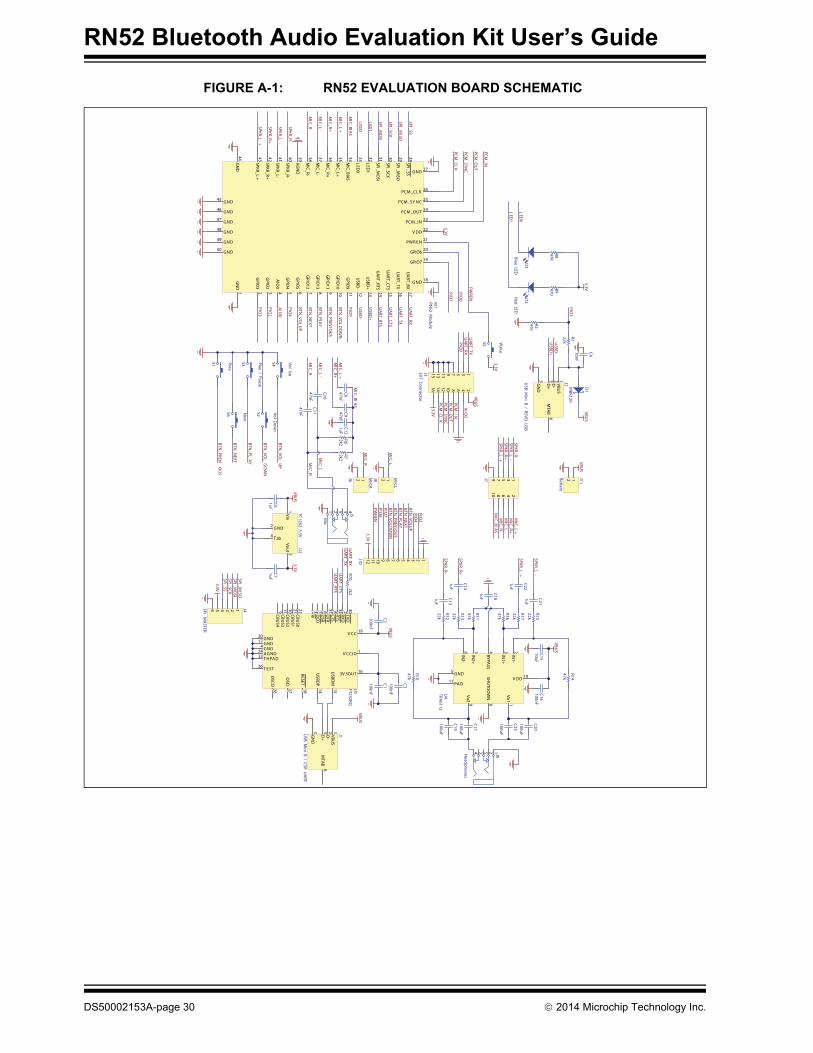
A.2 RN52 EVALUATION KITS SCHEMATIC
Figure A-1 shows the RN-52-EK schematic.
2014 Microchip Technology Inc. DS50002153A-page 29
RN52 Bluetooth Audio Evaluation Kit User’s Guide
FIGURE A-1: RN52 EVALUATION BOARD SCHEMATIC
VBUS
VBUS
RESET18
3V 3OUT 16USBD
P14
USBD
M15
GND17
CBUS2
10CBU
S121
V CCIO 1
CBUS3
11
CBUS4
9
CBUS0
22
GND20
RI3
DCD
7D
SR6
DTR
31CTS
8RTS
32RXD
2TXD
30
V CC 19
OSCI
27
OSCO
28
A GND24
T E ST26
GND4
T HPA D33
FT232RQU
1
GN
D5
D+
3D
-2
VBUS
1
MTA
B6
USB M
ini B / CSR UA
RT
J1
123456 J4SPI MA
STER
SPI_MISO
SPI_MO
SISPI_SCKSPI_SS
3.3V
UA
RT_RXU
ART_TX
UA
RT_CTSU
ART_RTS
Vin1
GND2Vout 3
T ab4
TC1262-3.3VU
2
1uFC6
1uFC7
VBUS
3.3V
100nF
C3100nF
C1
100nF
C2
Blue LED
D3
Red LED
D2
S2 Vol Dow
n
S3 Play / Pause
S6 Next
S1 Prev
S4 Vol Up
BTN_VO
LU
P
BTN_VO
LD
OW
N
BTN_N
EXT
BTN_PL
AY
BTN_PREVI
OU
S
47RR8
470R9
3.3V
GN
D5
D+
3D
-2
VBUS
1
MTA
B6
USB M
ini B / RSVD U
SB
J2
GPIO
45
GPIO
56
GPIO
127
GPIO
138
GPIO
119
GPIO
1010
GPIO
911
USBD
-12
USBD
+13
UA
RT_RTS14
UA
RT_CTS15
UA
RT_TX16
PCM_CL K 26
SPI_SS28
SPI_MISO
29
SPI_SCK30
PCM_IN 23
V DD 22
LED0
33
MIC_BIA
S34
MIC_L+
35
MIC_R+
36
MIC_L-
37
MIC_R-
38
PCM_OUT 24
GPIO7 19
PCM_SY NC 25
SPI_MO
SI31
LED1
32
PWR E N 21
GPIO6 20
UA
RT_RX17
AIO
04
GPIO
23
AG
ND
39
SPKR_R-40
GN
D1
GND 18
GND 27
GN
D44
GPIO
32
SPKR_L-41
GND50
GND49
GND48
GND47
GND46
GND45
SPKR_R+42
SPKR_L+
43
M1
RN52 M
odule
PIO7
PIO6
LED0
LED1
LED0
LED1
VBUS
USBD
-U
SBD+
SPI_MISO
SPI_MO
SI
SPI_SCK
SPI_SS
3.3V
SPKR_R-
SPKR_L-
SPKR_R+
SPKR_L+
S5 Wake
3.3V
PCM_CL
K
PCM_SYN
C
PCM_O
UT
PCM_IN
SPKR_R-
SPKR_L-
SPKR_R+
SPKR_L+
VBUS
47kR2
22k
R1PIO
3
1uF
C21
1uF
C22
1uF
C131uF
C14
1uFC12
2k2R7
2k2R6
47nFC847nF
C10
47nF
C11 47nFC9
MIC_L
MIC_R
1uF
C18
22k
R17
22k
R15
47k
R11
22k
R13
47k
R14
47k
R10
47k
R16
22k
R12
12
34
56
78
910
1112
1314
1516
J3EXT Connector PCM_CL
KPCM
_SYNC
PCM_O
UT
PCM_IN
3.3V
IN1+
3
IN1-
2
Vo29
BYPASS
4
IN2-
8
IN2+
7
SHU
TDO
WN
6
GND5
V DD 10
Vo11
PA D11
U4
TPA6112
100uF
C23100uF
C20
100uF
C17
100uF
C19
10uFC15
100nFC16
MBR120
D1
10nF
C4
VBUS
PIO9
3.3V
BTN_VO
LDO
WN
BTN_PREVIO
US
BTN_PLA
YBTN
_NEXT
BTN_VO
LUP
PIO2
PIO6
PIO7
12J8 MICL
12J6 MICR
MIC_L
MIC_R
12 J11
Battery
VBUS
123456789101112
J10
12
34
56
78
910
J7
PIO4
PWREN
PWREN
SPKR_R-SPKR_L
-SPKR_R+SPKR_L
+
MIC_BIA
S
MIC_L
+
MIC_R+
MIC_L
-
MIC_R-
MIC_L
+M
IC_R+M
IC_L-
MIC_R-
MIC_BIA
S
AIO
0
UA
RT_RX
UA
RT_TX
UA
RT_CTS
UA
RT_RTS
USBD
-
USBD
+
BTN_VO
LU
P
BTN_VO
LD
OW
N
BTN_N
EXT
BTN_PLA
Y
BTN_PREVIO
US
PIO3
PIO9
PIO2
PIO4
AIO
0
MIC_L
+M
IC_R+
MIC_L
-
MIC_R-
MIC_BIA
S
35 421 J5
Mic
3 54 2 1 J9Headphones
2k2R70
UA
RT_RXU
ART_TX
DS50002153A-page 30 2014 Microchip Technology Inc.

RN52 Audio Evaluation Kits Schematics
A.3 RN52 EVALUATION KITS PCB LAYOUT AND ASSEMBLE DRAWINGS
The RN52 Evaluation Board is a 2-layer, FR4, 0.062 inch, plated through a hole PCB construction. Figure A-2 through Figure A-7 show the PCB constructions and Assem-bly Drawings.
FIGURE A-2: RN52 EVALUATION BOARD TOP SILKSCREEN
FIGURE A-3: RN52 EVALUATION BOARD BOTTOM SILKSCREEN
2014 Microchip Technology Inc. DS50002153A-page 31

RN52 Bluetooth Audio Evaluation Kit User’s Guide
FIGURE A-4: RN52 EVALUATION BOARD TOP COPPER
FIGURE A-5: RN52 EVALUATION BOARD BOTTOM COPPER
DS50002153A-page 32 2014 Microchip Technology Inc.

RN52 Audio Evaluation Kits Schematics
FIGURE A-6: RN52 EVALUATION BOARD TOP ASSEMBLY
FIGURE A-7: RN52 EVALUATION BOARD BOTTOM ASSEMBLY
2014 Microchip Technology Inc. DS50002153A-page 33
RN52 Bluetooth Audio Evaluation Kit User’s Guide
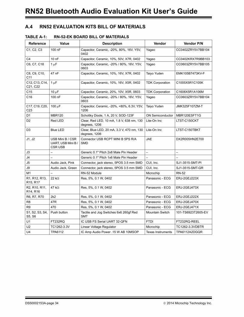
A.4 RN52 EVALUATION KITS BILL OF MATERIALS
TABLE A-1: RN-52-EK BOARD BILL OF MATERIALS
Reference Value Description Vendor Vendor P/N
C1, C2, C3 100 nF Capacitor, Ceramic, -20%, 80%, 16V, Y5V, 0402
Yageo CC0402ZRY5V7BB104
C4 10 nF Capacitor, Ceramic, 10%, 50V, X7R, 0402 Yageo CC0402KRX7R9BB103
C6, C7, C18 1 F Capacitor, Ceramic, -20% / 80%, 16V, Y5V, 0603
Yageo CC0603ZRY5V7BB105
C8, C9, C10, C11
47 nF Capacitor, Ceramic, 10%, 16V, X7R, 0402 Taiyo Yuden EMK105B7473KV-F
C12, C13, C14, C21, C22
1 F Capacitor, Ceramic, 10%, 16V, X5R, 0402 TDK Corporation C1005X5R1C105K
C15 10 F Capacitor, Ceramic, 20%, 10V, X5R, 0603 TDK Corporation C1608X5R1A106M
C16 100 nF Capacitor, Ceramic, -20% / 80%, 16V, Y5V, 0603
Yageo CC0603ZRY5V7BB104
C17, C19, C20, C23
100 F Capacitor, Ceramic, -20%, +80%, 6.3V, Y5V, 1206
Taiyo Yuden JMK325F107ZM-T
D1 MBR120 Schottky Diode, 1 A, 20 V, SOD-123F ON Semiconductor MBR120ESFT1G
D2 Red LED Clear, Red LED, 10 mA, 1.8 V, 638 nm, 130 degrees, 1206
Lite-On Inc LTST-C150CKT
D3 Blue LED Clear, Blue LED, 20 mA, 3.3 V, 470 nm, 130 degrees, 1206
Lite-On Inc LTST-C150TBKT
J1, J2 USB Mini B / CSR UART, USB Mini B / CSR USB
Connector USB RCPT MINI B 5PS R/A SMD
JAE DX2R005HN2E700
J3 – Generic 0.1" Pitch 2x8 Male Pin Header – –
J4 – Generic 0.1" Pitch 1x6 Male Pin Header – –
J5 Audio Jack, Pink Connector, jack stereo, 5POS 3.5 mm SMD CUI, Inc. SJ1-3515-SMT-PI
J9 Audio Jack, Green Connector, jack stereo, 5POS 3.5 mm SMD CUI, Inc. SJ1-3515-SMT-GR
M1 – RN-52 Module Microchip RN-52
R1, R12, R13, R15, R17
22 k Res, 5%, 0.1 W, 0402 Panasonic - ECG ERJ-2GEJ223X
R2, R10, R11, R14, R16
47 k Res, 5%, 0.1 W, 0402 Panasonic - ECG ERJ-2GEJ473X
R6, R7, R70 2k2 Res, 5%, 0.1 W, 0402 Panasonic - ECG ERJ-2GEJ222X
R8 47R Res, 5%, 0.1 W, 0402 Panasonic - ECG ERJ-2GEJ470X
R9 470 Res, 5%, 0.1 W, 0402 Panasonic - ECG ERJ-2GEJ471X
S1, S2, S3, S4, S5, S6
Push button Tactile and Jog Switches 6x6 260gf Red SMT
Mountain Switch 101-TS6923T2605-EV
U1 FT232RQ IC USB FS Serial UART 32-QFN FTDI FT232RQ-REEL
U2 TC1262-3.3V Linear Voltage Regulator Microchip TC1262-3.3VDBTR
U4 TPA6112 IC Amp Audio Power .15 W AB 10MSOP Texas Instruments TPA6112A2DGQR
DS50002153A-page 34 2014 Microchip Technology Inc.

RN52 Audio Evaluation Kits Schematics
A.5 RN52 EVALUATION KITS PHYSICAL DIMENSIONS
Figure A-8 shows the physical dimensions of the RN52 Evaluation Board.
FIGURE A-8: RN-52 PHYSICAL DIMENSIONS
2014 Microchip Technology Inc. DS50002153A-page 35

RN52 Bluetooth Audio Evaluation Kit User’s Guide
NOTES:
DS50002153A-page 36 2014 Microchip Technology Inc.

DS50002153A-page 37 2014 Microchip Technology Inc.
AMERICASCorporate Office2355 West Chandler Blvd.Chandler, AZ 85224-6199Tel: 480-792-7200 Fax: 480-792-7277Technical Support: http://www.microchip.com/supportWeb Address: www.microchip.com
AtlantaDuluth, GA Tel: 678-957-9614 Fax: 678-957-1455
Austin, TXTel: 512-257-3370
BostonWestborough, MA Tel: 774-760-0087 Fax: 774-760-0088
ChicagoItasca, IL Tel: 630-285-0071 Fax: 630-285-0075
ClevelandIndependence, OH Tel: 216-447-0464 Fax: 216-447-0643
DallasAddison, TX Tel: 972-818-7423 Fax: 972-818-2924
DetroitNovi, MI Tel: 248-848-4000
Houston, TX Tel: 281-894-5983
IndianapolisNoblesville, IN Tel: 317-773-8323Fax: 317-773-5453
Los AngelesMission Viejo, CA Tel: 949-462-9523 Fax: 949-462-9608
New York, NY Tel: 631-435-6000
San Jose, CA Tel: 408-735-9110
Canada - TorontoTel: 905-673-0699 Fax: 905-673-6509
ASIA/PACIFICAsia Pacific OfficeSuites 3707-14, 37th FloorTower 6, The GatewayHarbour City, KowloonHong KongTel: 852-2401-1200Fax: 852-2401-3431
Australia - SydneyTel: 61-2-9868-6733Fax: 61-2-9868-6755
China - BeijingTel: 86-10-8569-7000 Fax: 86-10-8528-2104
China - ChengduTel: 86-28-8665-5511Fax: 86-28-8665-7889
China - ChongqingTel: 86-23-8980-9588Fax: 86-23-8980-9500
China - HangzhouTel: 86-571-8792-8115 Fax: 86-571-8792-8116
China - Hong Kong SARTel: 852-2943-5100 Fax: 852-2401-3431
China - NanjingTel: 86-25-8473-2460Fax: 86-25-8473-2470
China - QingdaoTel: 86-532-8502-7355Fax: 86-532-8502-7205
China - ShanghaiTel: 86-21-5407-5533 Fax: 86-21-5407-5066
China - ShenyangTel: 86-24-2334-2829Fax: 86-24-2334-2393
China - ShenzhenTel: 86-755-8864-2200 Fax: 86-755-8203-1760
China - WuhanTel: 86-27-5980-5300Fax: 86-27-5980-5118
China - XianTel: 86-29-8833-7252Fax: 86-29-8833-7256
China - XiamenTel: 86-592-2388138 Fax: 86-592-2388130
China - ZhuhaiTel: 86-756-3210040 Fax: 86-756-3210049
ASIA/PACIFICIndia - BangaloreTel: 91-80-3090-4444 Fax: 91-80-3090-4123
India - New DelhiTel: 91-11-4160-8631Fax: 91-11-4160-8632
India - PuneTel: 91-20-3019-1500
Japan - OsakaTel: 81-6-6152-7160 Fax: 81-6-6152-9310
Japan - TokyoTel: 81-3-6880- 3770 Fax: 81-3-6880-3771
Korea - DaeguTel: 82-53-744-4301Fax: 82-53-744-4302
Korea - SeoulTel: 82-2-554-7200Fax: 82-2-558-5932 or 82-2-558-5934
Malaysia - Kuala LumpurTel: 60-3-6201-9857Fax: 60-3-6201-9859
Malaysia - PenangTel: 60-4-227-8870Fax: 60-4-227-4068
Philippines - ManilaTel: 63-2-634-9065Fax: 63-2-634-9069
SingaporeTel: 65-6334-8870Fax: 65-6334-8850
Taiwan - Hsin ChuTel: 886-3-5778-366Fax: 886-3-5770-955
Taiwan - KaohsiungTel: 886-7-213-7830
Taiwan - TaipeiTel: 886-2-2508-8600 Fax: 886-2-2508-0102
Thailand - BangkokTel: 66-2-694-1351Fax: 66-2-694-1350
EUROPEAustria - WelsTel: 43-7242-2244-39Fax: 43-7242-2244-393Denmark - CopenhagenTel: 45-4450-2828 Fax: 45-4485-2829
France - ParisTel: 33-1-69-53-63-20 Fax: 33-1-69-30-90-79
Germany - DusseldorfTel: 49-2129-3766400
Germany - MunichTel: 49-89-627-144-0 Fax: 49-89-627-144-44
Germany - PforzheimTel: 49-7231-424750
Italy - Milan Tel: 39-0331-742611 Fax: 39-0331-466781
Italy - VeniceTel: 39-049-7625286
Netherlands - DrunenTel: 31-416-690399 Fax: 31-416-690340
Poland - WarsawTel: 48-22-3325737
Spain - MadridTel: 34-91-708-08-90Fax: 34-91-708-08-91
Sweden - StockholmTel: 46-8-5090-4654
UK - WokinghamTel: 44-118-921-5800Fax: 44-118-921-5820
Worldwide Sales and Service
03/13/14