
Rmbridgee Modguide
66
RM Bridge Professional Engineering Software for Bridges of all Types MODELER USER GUIDE RM Bridge V8i August 2012
description
medeler guide for RM user
Transcript of Rmbridgee Modguide

RM Bridge Professional Engineering Software for Bridges of all Types
MODELER USER GUIDE
RM Bridge V8i
August 2012

RM Bridge
M o d e l e r U s e r G u i d e
© Bentley Systems Austria
This document is an integral part of the program package RM Bridge. Duplication and
dissemination is only allowed with explicit permission of Bentley Systems,
Incorporated.
© 2012, Bentley Systems, Incorporated. All Rights Reserved.

RM Bridge Contents
M o d e l e r U s e r G u i d e I
© Bentley Systems Austria
Contents
1 General Information ............................................................................................... 1-1
1.1 Introduction .................................................................................................... 1-1
1.2 Program Start ................................................................................................. 1-1
1.3 Input Conventions .......................................................................................... 1-2
1.4 Definitions ..................................................................................................... 1-3
1.4.1 Bridge Axes ............................................................................................... 1-3
1.4.2 Segments .................................................................................................... 1-3
1.4.3 Cross-Sections ........................................................................................... 1-5
1.4.4 Parts ........................................................................................................... 1-5
1.4.5 Variables .................................................................................................... 1-8
2 Main Input Window ............................................................................................... 2-1
2.1 Program Version, Project Directory .............................................................. 2-2
2.2 General Toolbar ............................................................................................. 2-2
2.3 Navigation Panel ............................................................................................ 2-3
2.4 Unit Control ................................................................................................... 2-3
2.5 Axis, Cross-Section and Segment List Windows .......................................... 2-3
2.6 Edit Functions ................................................................................................ 2-4
2.7 Zoom functions .............................................................................................. 2-4
2.7.1 Icons ........................................................................................................... 2-5
2.7.2 Free-Hand Symbols ................................................................................... 2-5
2.8 Modeling Functions ....................................................................................... 2-6
2.9 Recalculation Functions ................................................................................. 2-7
2.10 File Functions ................................................................................................ 2-7
3 Plan View Geometry .............................................................................................. 3-1
3.1 Introduction .................................................................................................... 3-1
3.2 Toolbar for Horizontal Axis Construction ..................................................... 3-1
3.3 3D Points ........................................................................................................ 3-2

RM Bridge Contents
M o d e l e r U s e r G u i d e I I
© Bentley Systems Austria
4 Vertical View Geometry ........................................................................................ 4-1
4.1 Introduction .................................................................................................... 4-1
4.2 Toolbar for Vertical Axis Construction ......................................................... 4-2
5 Cross-Section Definition ........................................................................................ 5-1
5.1 Introduction .................................................................................................... 5-1
5.2 Construction Line (CL) Toolbar .................................................................... 5-3
5.3 Variables and Cross-Section Input ................................................................ 5-6
5.4 Part, Formula and Point Lists ........................................................................ 5-6
5.5 Layers ............................................................................................................. 5-6
5.6 Cross-Section Lock ........................................................................................ 5-7
5.7 Element Definition ......................................................................................... 5-7
5.7.1 Icons ........................................................................................................... 5-7
5.7.2 Individual Mesh Refinement ..................................................................... 5-9
5.7.3 Copying Elements ...................................................................................... 5-9
5.8 Link Segments ............................................................................................. 5-11
5.8.1 Principles ................................................................................................. 5-11
5.8.2 Link Segment Cross-Section ................................................................... 5-12
5.9 Reference Points .......................................................................................... 5-13
5.9.1 Icons ......................................................................................................... 5-13
5.9.2 Local Mesh Refinement ........................................................................... 5-13
5.10 Dimension Line ............................................................................................ 5-15
5.11 Import and Management of Cross-Sections ................................................. 5-15
6 Formulas ................................................................................................................ 6-1
6.1 Introduction .................................................................................................... 6-1
6.2 Expressions and Tables .................................................................................. 6-1
6.3 Formula Input Window .................................................................................. 6-3
7 Segment Definition ................................................................................................ 7-1
7.1 Introduction .................................................................................................... 7-1
7.2 Further Functions in the “Segment Management Window” .......................... 7-3
7.2.1 Connections between two nodes ................................................................ 7-4
7.2.2 Modelling Supports with Spring Elements ................................................ 7-7

RM Bridge Contents
M o d e l e r U s e r G u i d e I I I
© Bentley Systems Austria
7.2.3 Cross members ......................................................................................... 7-10
7.3 Copying Segments or Sequences ................................................................. 7-14
7.3.1 Copying Complete Segments ................................................................... 7-14
7.3.2 Copying Sequences of a Segment ............................................................ 7-14
7.4 Existing FE-Cross-Sections at the Segment Points ..................................... 7-16
7.5 Active Segment Point Details ...................................................................... 7-16
7.6 Stay cable input ............................................................................................ 7-17
7.7 Segment Type „Free Pier“ ........................................................................... 7-17
7.8 Link Segments ............................................................................................. 7-17
8 Creating the RmBridge Analysis Model ................................................................ 8-1

RM Bridge General Information
M o d e l e r U s e r G u i d e 1 - 1
© Bentley Systems Austria
1 General Information
1.1 Introduction
Every structural analysis is based on mathematical models. The quality of the answers
gained from such models depends strongly on the quality of the approximations and
generalizations that underlie each particular model.
Such approximations are necessary to describe geometric properties and the resistance
behavior of structures among others.
The Modeler of RmBridge (formerly geometric preprocessor GP) was invented in order
to achieve high accuracy in describing the geometry of bridges.
The RmBridge Modeler is a geometric pre-processor for the definition of structural
bridge systems. It supports the construction of road axes in both plan view and elevation
and generates structural information for bridges along such road axes. Powerful
interactive tools allow the definition of cross-sections for these bridges. The Modeler
transforms the individual axes together with the associated cross-sections into a
structural database and makes this information available for analysis in RmBridge.
Describing general concepts and the basic program functions is the aim of this ‘Modeler
User Guide’. Detailed input descriptions are given through online help texts by pressing
the <F1> -button. They are not repeated in this book.
The input follows some basic rules, which comply with most Windows applications.
The database of the Modeler is part of the RmBridge database. However, it consists of
files (gpdata*.gp9) which are separate from the actual analysis database (db-*.rm9) of
RmBridge. The Modeler database is stored in the RmBridge project directory in parallel
tot he analysis database. The file management is either done by respective functions in
the Modeler or by Windows applications such as the Windows Explorer.
General bridge modeling concepts are discussed in the “RmBridge Analysis User
Guide”.
1.2 Program Start
The Modeler is started in the main menu of RmBridge, either by selecting the main
menu function Modeler, or by selecting the respective function <Modeler in the
navigation tree.
The main input window with presentation of the axes in plan is presented on selecting
the Modeler (see Figure 8 - Main input window). In this window, new axes can be input
and existing axes modified. The main graphic presentation window of the Modeler
overlaps the main graphics window of RmBridge. The small RmBridge graphics
window beneath the navigation tree remains related to the RmBridge analysis database

RM Bridge General Information
M o d e l e r U s e r G u i d e 1 - 2
© Bentley Systems Austria
and shows the current calculation model. The navigation window remains unchanged,
only the sub-functions of the Modeler are presented in addition to the RmBridge
analysis functions.
Any already defined axes are directly presented in the graphics window when the
Modeler is started. An empty window appears if no axes have yet been defined. The
respective icons for defining or modifying axes are arranged at the left edge of the
graphics window. The user can switch to the other functions of the Modeler, e.g. cross-
section definition or segment definition, by selecting the respective function in the
navigation tree.
On selecting the exit button ( -Icon) or any other RmBridge function outside the
modeler, the program leaves the Modeler level and returns to the RmBridge analysis
level (without automatic update of the RmBridge analysis model). The analysis model
update is performed by pressing the Remodel button replacing in the Modeler the
RmBridge Recalc button (see section 2.1 and chapter 8).
1.3 Input Conventions
All communication between the user and the Modeler is done interactively and all
modifications to the model are updated immediately in the representations on the
graphic screen. A special input sequence is not required – any part of the structure can
be defined independently - and default values are usually provided for information that
is not explicitly entered. The structural data can be passed on to the analysis database of
RmBridge at any point, and more information can be added to the analysis model at a
later stage with using the input functions provided directly in the RmBridge GUI.
Two types of input windows are used in the Modeler: Multi-tasking windows and
single-tasking windows. Multi tasking windows can be opened and worked on
simultaneously. They are not active when a single-tasking window is open. Single-
tasking windows are used for the definition of objects and must be closed by clicking on
<Ok> or <Cancel> .
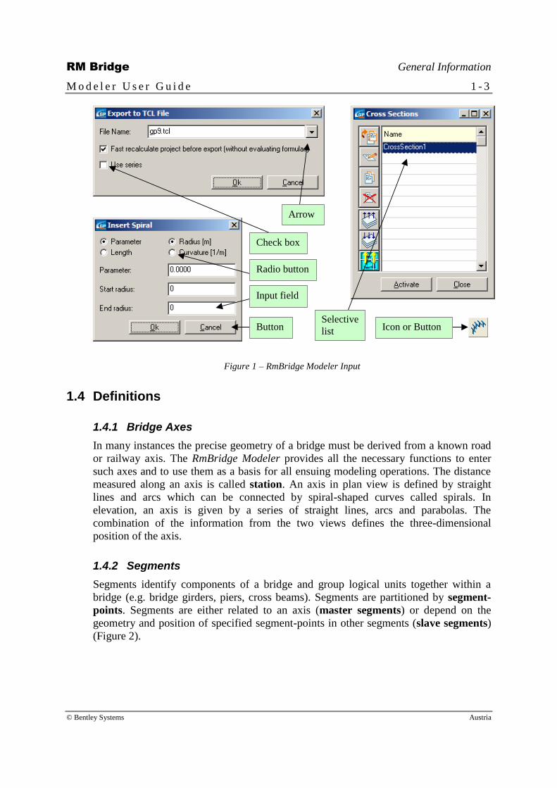
Input fields within such input windows provide the means to enter numbers or strings,
so-called radio buttons offer choices of alternative options and check-boxes (or option
fields) allow the activation or de-activation of program options which do not exclude
each other. Buttons are used to trigger actions such as <Ok> or <Calculate> while
icons or symbols call whole program sequences which usually require additional input
through input windows.
Existing objects are often represented in selective lists which are usually accessed by
clicking the arrow next to an input window (Figure 1), or by double clicking on the
corresponding line.
RM Bridge General Information
M o d e l e r U s e r G u i d e 1 - 3
© Bentley Systems Austria
Icon or Button
Radio button
Input field
Button Selective
list
Check box
Arrow
Figure 1 – RmBridge Modeler Input
1.4 Definitions
1.4.1 Bridge Axes
In many instances the precise geometry of a bridge must be derived from a known road
or railway axis. The RmBridge Modeler provides all the necessary functions to enter
such axes and to use them as a basis for all ensuing modeling operations. The distance
measured along an axis is called station. An axis in plan view is defined by straight
lines and arcs which can be connected by spiral-shaped curves called spirals. In
elevation, an axis is given by a series of straight lines, arcs and parabolas. The
combination of the information from the two views defines the three-dimensional
position of the axis.
1.4.2 Segments
Segments identify components of a bridge and group logical units together within a
bridge (e.g. bridge girders, piers, cross beams). Segments are partitioned by segment-
points. Segments are either related to an axis (master segments) or depend on the
geometry and position of specified segment-points in other segments (slave segments)
(Figure 2).

RM Bridge General Information
M o d e l e r U s e r G u i d e 1 - 4
© Bentley Systems Austria
Axis
Bridge
Main
girders
Piers
Cross
beams
Axis Structural
points
Master segment (main girders)
Slave
origin
Slave
reference
line
Reference
line for pier
Supports Pylon
Figure 2 - Master segments and slave segments
Segments are connected at segment-points. The slave origin specifies the position of
the reference line for the slave segment. The connection point(s) specify the position of
the physical connection between segments. These connections in the structural model
are usually made with eccentric spring elements with a physical length of zero. Each
segment-point becomes a node in RmBridge and structural elements are generated
between each two neighboring nodes within a segment for the analysis in RmBridge.

RM Bridge General Information
M o d e l e r U s e r G u i d e 1 - 5
© Bentley Systems Austria
Slave reference line
Segment points Segment point
(master)
Slave origin
Segment point
slave
Eccentric
connections
Spring
elements Connection
points
Figure 3 - Connection between master segment and slave segment
1.4.3 Cross-Sections
Cross-sections of segments are modeled with cross-section elements (Figure 4). These
three and four-sided elements are used in RmBridge to compute all relevant cross-
section properties.
Certain reference points within the cross-section such as reinforcement-points, stress
check points, connection points, temperature points or geometry points can be identified
during the cross-section input sequence in the Modeler.
1 1 1 1 1 1 1 1
2 2
2 2
2 2
2 2
1 1 1 1 1 1 1 1
1 1
1 1 1 1 Part
numbers
Segment points
Figure 4 - Cross-sections and Cross-section elements.
1.4.4 Parts
Cross-sections can be split into parts. Each part consists of a number of cross-section
elements or, alternatively, a number of other parts (Figure 4, Figure 5). These parts can
be referenced to create a multiple series of structural elements within a single segment.
Parts can also be used to define composite action within a beam, consisting of two to
eight parts (Figure 6).

RM Bridge General Information
M o d e l e r U s e r G u i d e 1 - 6
© Bentley Systems Austria
Only web
(cross-section A)
Only flange
(cross-section B)
Composite section
(cross-section C=A+ B)
Segment points
= Nodes
Figure 5 - Flange & web forming a composite cross-section

RM Bridge General Information
M o d e l e r U s e r G u i d e 1 - 7
© Bentley Systems Austria
Modeler:
1 series of segment points
1 part
RmBridge:
1 series of structural nodes
1 series of structural elements
Modeler:
1 series of segment points
3 parts (A, B, C=A+B)
RmBridge:
1 series of structural nodes
3 series of structural elements
Modeler:
1 series of segment points
2 parts (A, B)
RmBridge:
2 series of structural nodes
2 series of structural elements
A
B
C=A+B
(composite)
Modeler:
1 series of segment points
12 parts (A-K)
RmBridge:
4 series of structural nodes
12 series of structural elements
B
A
E
D
H
G
K
J
C=A+B F=D+E L=J+K I=G+H
B A
Figure 6 - Examples for parts forming various cross-sections

RM Bridge General Information
M o d e l e r U s e r G u i d e 1 - 8
© Bentley Systems Austria
1.4.5 Variables
Certain geometric parameters may vary along an axis according to simple mathematical
rules (e.g. variations in cross-sections (Figure 7), distance of lanes from the main axis).
These rules, or functions, can be entered and referenced in the relevant input sequences.
H=f(station)
t=f(station)
Figure 7 - Cross-section shape & formulas

RM Bridge Main Input Window
M o d e l e r U s e r G u i d e 2 - 1
© Bentley Systems Austria
2 Main Input Window
When the Modeler has been started, the main input window as shown in Figure 8 is
displayed. Axes, cross-sections, segments etc. may be defined with the respective
functions in the navigation tree, and the data are graphically presented in the graphics
window. The main window is also the input pad for axis definition in plan view.
Status-bar
Menu bar
Main toolbar
3D-view toolbar
3D-view orientation
Main 3D-View
Detailed
3D-View
Navigation
tree window
Figure 8 - Main input window
Program
version
Project
directory
Application
control

RM Bridge Main Input Window
M o d e l e r U s e r G u i d e 2 - 2
© Bentley Systems Austria
2.1 Program Version, Project Directory
The top-most line of the window is related to the super-ordinate RmBridge project and
shows the active project directory and the release number of used RmBridge program
version. The application control button at the top right allows for the program to be
minimized into a small icon (usually at the bottom of the window) or to maximize
the window. Only the -button is related to the Modeler session. It terminates the
Modeler input session and the program returns to the RmBridge analysis level.
However, no update of the analysis model is automatically performed when the Modeler
level is left.
In order to check the Modeler data, to create the respective geometry data of the
analysis model and to update the analysis model in the RmBridge database, the function
Remodel must be selected and started with the corresponding options (see chapter 8,
Creating the RmBridge Analysis Model).
2.2 General Toolbar
This toolbar provides access to some basic functions which can be called upon at any
point in an RmBridge session.
......... <show log-file> View history of program logs.
......... <explorer> Open the current project folder in windows-explorer.
......... <error> View warnings and errors of the recent calculation.
......... <calculator> Open windows calculator.
......... <text editor> Open and edit text files from the current project.
......... <Crt> Open and view plot files from the current project.
......... <freehand symbols> Show freehand symbols for view settings.
......... <RM-setup> Change GUI presentation parameters.
......... <print> Print plot files.
......... <help> View online help.

RM Bridge Main Input Window
M o d e l e r U s e r G u i d e 2 - 3
© Bentley Systems Austria
......... <manuals> View user guides online.
......... <Tdf> View tdf-report files.
2.3 Navigation Panel
In the navigation panel you can switch between three tabs:
<Navigation>: Selection of the different RmBridge functions or
sub-functions of the modeler respectively (axes, cross-sections, segments, ...). If
a super-ordinate RmBridge function is selected, the program leaves the Modeler
level without update of the analysis model and returns to the RmBridge level.
Within the Modeler the functions for defining and modifying axes, cross-section,
segments, etc. can be easily selected.
< >> >: Recent projects list. The previously used project directories are
listed. With double click it is easy to switch between different projects
(equivalent to File Open RmBridge Project.
<Disk:Size>: Allows for using Windows Explorer features within the project
directory.
2.4 Unit Control
In the configuration window shown on selecting Modeler Options Units the user
can change the units of the Modeler database for structural dimensions, cross-section
dimension, angles and temperatures. The data in the database are then presented in the
selected units in all input and output windows of the Modeler.
In general, all user-defined units shall be defined in the super-ordinate RmBridge level,
and to avoid defining deviating units in the Modeler. Different units in the analysis
model and the Modeler may cause severe problems, especially if variables as tables or
mathematical expressions are defined and used in the project.
2.5 Axis, Cross-Section and Segment List Windows
Every project may consist of an unlimited number of axes, segments or cross-sections.
Input actions always refer to the active object that is displayed in the corresponding
window. Clicking on the axis, cross-section or segment list icons at the top right of the
main window (Figure 8) leads to an input list, which contains all existing objects of the
selected type. Use the functions described in chapter 2.6 to modify the list or click on
the object in the list which needs to be activated for the ensuing input actions.
RM Bridge Main Input Window
M o d e l e r U s e r G u i d e 2 - 4
© Bentley Systems Austria
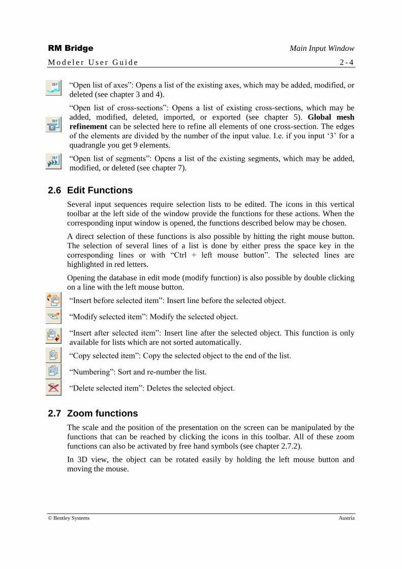
“Open list of axes”: Opens a list of the existing axes, which may be added, modified, or
deleted (see chapter 3 and 4).
“Open list of cross-sections”: Opens a list of existing cross-sections, which may be
added, modified, deleted, imported, or exported (see chapter 5). Global mesh
refinement can be selected here to refine all elements of one cross-section. The edges
of the elements are divided by the number of the input value. I.e. if you input ‘3’ for a
quadrangle you get 9 elements.
“Open list of segments”: Opens a list of the existing segments, which may be added,
modified, or deleted (see chapter 7).
2.6 Edit Functions
Several input sequences require selection lists to be edited. The icons in this vertical
toolbar at the left side of the window provide the functions for these actions. When the
corresponding input window is opened, the functions described below may be chosen.
A direct selection of these functions is also possible by hitting the right mouse button.
The selection of several lines of a list is done by either press the space key in the
corresponding lines or with “Ctrl + left mouse button”. The selected lines are
highlighted in red letters.
Opening the database in edit mode (modify function) is also possible by double clicking
on a line with the left mouse button.
“Insert before selected item”: Insert line before the selected object.
“Modify selected item”: Modify the selected object.
“Insert after selected item”: Insert line after the selected object. This function is only
available for lists which are not sorted automatically.
“Copy selected item”: Copy the selected object to the end of the list.
“Numbering”: Sort and re-number the list.
“Delete selected item”: Deletes the selected object.
2.7 Zoom functions
The scale and the position of the presentation on the screen can be manipulated by the
functions that can be reached by clicking the icons in this toolbar. All of these zoom
functions can also be activated by free hand symbols (see chapter 2.7.2).
In 3D view, the object can be rotated easily by holding the left mouse button and
moving the mouse.

RM Bridge Main Input Window
M o d e l e r U s e r G u i d e 2 - 5
© Bentley Systems Austria
2.7.1 Icons
“Full view”: Fit the entire project to the screen.
“Enlarge”, “Smaller”: Zoom into / out of the current plot.
“Shift left”, “Shift right”: Move the current plot left / right.
“Shift up”, “Shift down”: Move the current plot up / down.
“Redraw view”: Redraw the current screen.
2.7.2 Free-Hand Symbols
The RmBridge Modeler also recognizes a range of so-called free-hand symbols for
different screen manipulations. These functions are available in all graphic windows.
The symbols are drawn using the left mouse button while holding down the <Ctrl> -
button at the same time. The following symbols are available:
RM Bridge Main Input Window
M o d e l e r U s e r G u i d e 2 - 6
© Bentley Systems Austria
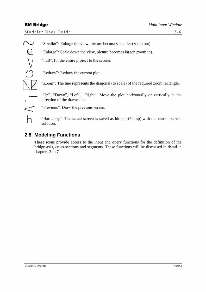
“Smaller”: Enlarge the view; picture becomes smaller (zoom out).
“Enlarge”: Scale down the view, picture becomes larger (zoom in).
“Full”: Fit the entire project to the screen.
“Redraw”: Redraw the current plot.
“Zoom”: The line represents the diagonal (to scale) of the required zoom rectangle.
“Up”, “Down”, “Left”, “Right”: Move the plot horizontally or vertically in the
direction of the drawn line.
“Previous”: Draw the previous screen.
“Hardcopy”: The actual screen is saved as bitmap (*.bmp) with the current screen
solution.
2.8 Modeling Functions
These icons provide access to the input and query functions for the definition of the
bridge axis, cross-sections and segments. These functions will be discussed in detail in
chapters 3 to 7.

RM Bridge Main Input Window
M o d e l e r U s e r G u i d e 2 - 7
© Bentley Systems Austria
“Open 3D-view”: Opens the window for a three-dimensional view of the defined
structure.
“Show ground plan”: Pops up the plan view window. (see chapter 3, Plan View
Geometry).
“Show elevation window”: Opens the input window for the definition of the axis in
vertical view (see chapter 4, Vertical View Geometry).
“Show cross-section window”: Opens the input window for the definition of cross-
sections (see chapter 5, Cross-Section Definition).
“Open segment points of current segment”: Opens the input window for section points
(see chapter 7, Segment Definition).
“Opens list of formulas and tables”: Opens the input window for arithmetic formulas
and tables (see chapter 6, Formulas).
2.9 Recalculation Functions
“Fast recalculation”: This button can be used to calculate all assigned FE-cross-sections
in the segment list.
“Recalculation with formula evaluation”: This button can be used to update FE-cross-
sections after a formula or table has been modified. In contrast to the button above, all
variable values are calculated by evaluating the formula and table expressions. This
type of calculation is more time consuming and is only necessary if a used formula or
table has been changed before.
2.10 File Functions
The functions in this toolbar manage the import and the export of data.
“Import from TCL file”: Data are read from an ASCII file created by ASCII export of
the Modeler database. The objects are transferred into the database. Note that only files
containing Modeler data can be read within the Modeler. These are TCL files created
from the Modeler level. TCL files describing the RmBridge analysis model cannot be
read, if the Modeler level is active.
“Export to TCL file”: The Modeler database is read and stored in an ASCII file in TCL
format for backup purposes (default name gp9.tcl). .
RM Bridge Plan View Geometry
M o d e l e r U s e r G u i d e 3 - 1
© Bentley Systems Austria
3 Plan View Geometry
3.1 Introduction
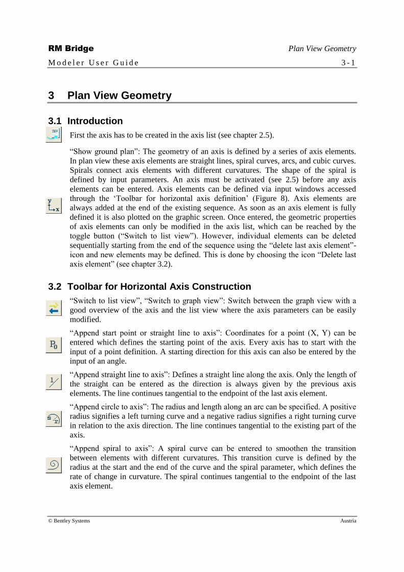
First the axis has to be created in the axis list (see chapter 2.5).
“Show ground plan”: The geometry of an axis is defined by a series of axis elements.
In plan view these axis elements are straight lines, spiral curves, arcs, and cubic curves.
Spirals connect axis elements with different curvatures. The shape of the spiral is
defined by input parameters. An axis must be activated (see 2.5) before any axis
elements can be entered. Axis elements can be defined via input windows accessed
through the ‘Toolbar for horizontal axis definition’ (Figure 8). Axis elements are
always added at the end of the existing sequence. As soon as an axis element is fully
defined it is also plotted on the graphic screen. Once entered, the geometric properties
of axis elements can only be modified in the axis list, which can be reached by the
toggle button (“Switch to list view”). However, individual elements can be deleted
sequentially starting from the end of the sequence using the “delete last axis element”-
icon and new elements may be defined. This is done by choosing the icon “Delete last
axis element” (see chapter 3.2).
3.2 Toolbar for Horizontal Axis Construction
“Switch to list view”, “Switch to graph view”: Switch between the graph view with a
good overview of the axis and the list view where the axis parameters can be easily
modified.
“Append start point or straight line to axis”: Coordinates for a point (X, Y) can be
entered which defines the starting point of the axis. Every axis has to start with the
input of a point definition. A starting direction for this axis can also be entered by the
input of an angle.
“Append straight line to axis”: Defines a straight line along the axis. Only the length of
the straight can be entered as the direction is always given by the previous axis
elements. The line continues tangential to the endpoint of the last axis element.
“Append circle to axis”: The radius and length along an arc can be specified. A positive
radius signifies a left turning curve and a negative radius signifies a right turning curve
in relation to the axis direction. The line continues tangential to the existing part of the
axis.
“Append spiral to axis”: A spiral curve can be entered to smoothen the transition
between elements with different curvatures. This transition curve is defined by the
radius at the start and the end of the curve and the spiral parameter, which defines the
rate of change in curvature. The spiral continues tangential to the endpoint of the last
axis element.

RM Bridge Plan View Geometry
M o d e l e r U s e r G u i d e 3 - 2
© Bentley Systems Austria
“Append cubic curve to axis”: A cubic element is connected to the previous axis
element. The input can be done either by radius with start and end radius or curvature
with start and end curvature. The curve continues tangentially to the endpoint of the
last axis element.
“Delete last axis element”: The undo icon deletes the last axis element in the active axis
after this action is confirmed one more time. This action can be repeated to delete
further axis segments.
3.3 3D Points
In addition to the axis definition the Modeler allows for defining and managing arbitrary
points in space. These points are named objects with the coordinates in space as
properties. They can be used in various situations as reference objects (e.g. as start point
of “Segments”).
The 3D point management also offers interfaces to other programs with a point database
(e.g. road planning software or geodesy programs). They allow taking over points from
point lists of other programs or storing such point lists for being used in other programs.
Note that the sequence of the coordinate values is X, Z, Y in the RmBridge coordinate
system, corresponding to the common sequence in geodesy applications, where X and Y
are the coordinate in ground plan and Z indicates the altitude.

RM Bridge Vertical View Geometry
M o d e l e r U s e r G u i d e 4 - 1
© Bentley Systems Austria
4 Vertical View Geometry
4.1 Introduction
First the axis has to be created in the axis list (see chapter 2.5).
“Show elevation window”: The axis elements to describe the geometry of an axis in
elevated view available in the Modeler are straight lines, arcs and parabolas. These axis
elements can be entered in two ways: sequentially, or as a tangent polygon to be
rounded with parabolas in a further step. Horizontal co-ordinates and distances in these
input procedures are always measured along the axis (station). The station range of the
axis definition in elevated view may differ from that in plan view. A mouse-click on
the corresponding icon in the ‘Modeling functions’ toolbar (see chapter 2.8, Modeling
Functions and Figure 8) activates the input window for the axis in elevation as shown
in Figure 9.
Please note that an axis must be activated in the “Axis management window” and that
every axis must be defined in all three dimensions, i.e. in plan and elevated view.
Name of the active axis Close window
Graphic screen for
the axis in vertical
projection
Toolbar for vertical
axis construction
Status and prompt
Zoom functions
Figure 9 - Input window for axes in vertical view

RM Bridge Vertical View Geometry
M o d e l e r U s e r G u i d e 4 - 2
© Bentley Systems Austria
4.2 Toolbar for Vertical Axis Construction
“Switch to list view”, “Switch to graph view”: Switch between the graph view with a
good overview of the axis and the list view where the corresponding values can be
easily modified.
“Append start point or straight line to axis”: Coordinates for a point (X, Y) can be
entered which defines the starting point of the axis. Every axis has to start with the
input of a point definition. A starting direction for this axis can also be entered by the
input of an angle.
“Append straight line by station”: A straight line of specified length can be entered.
The line continues tangential to the endpoint of the last axis element.
“Append straight line by station and height”: Defining the station or station increment
and the elevation at the end of the line specifies a straight line. The line continues
tangential to the endpoint of the last axis element.
“Append circle by station and radius”: Defines an arc. A radius and the length of the
arc can be entered. The arc continues tangential to the endpoint of the last axis element.
“Append circle by station and height”: The station or station increment in combination
with the elevation of the axis at the end define the geometry an arc element. The circle
continues tangential to the endpoint of the last axis element.
“Append parabola to axis”: A parabolic element is defined by the elevation at the end
and a station or station increment. The parabola continues tangential to the endpoint of
the last axis element.
“Delete last axis element”: The undo icon deletes the last axis element in the active
series after one more confirmation. This action can be repeated to delete further axis
segments.
“Parabola by rounding a tangent point”: Fits a parabola between two tangential straight
lines.
“Parabola by rounding a polygon of 3 lines”: Fits a parabola to a series of three straight
lines. The first and third straight line each serve as a tangent to the parabola and the
middle line is eliminated after clicking on this line.

RM Bridge Cross-Section Definition
M o d e l e r U s e r G u i d e 5 - 1
© Bentley Systems Austria
5 Cross-Section Definition
5.1 Introduction
The geometry of cross-sections is defined by connecting intersection points of
construction lines (CL). Construction lines are entered using the tools in the CL-toolbar
at the top left hand side of the Cross-section input window (Figure 12). Each
construction line (CL) is constructed in relation to at least one other construction line or
to one of the two default construction lines ‘CL1’ and ‘CL2’, the two axes of the cross-
section. The intersection point of ‘CL1’ and ‘CL2’ marks the point where the axis
intersects the cross-section plane.
Each cross-section is partitioned into cross-section elements. A cross-section element is
a two-dimensional three or four-sided area enclosed by parts of CL's. All relevant cross-
sectional properties are computed from this cross-section element mesh, the direction of
input has no influence on the result. Adjacent cross-section elements must share corner
nodes to ensure correct connectivity in the cross-section element mesh (Figure 10), even
across part boundaries.
The sides of the cross-section elements must not intersect.
1 1 1
2
2
2
wrong
1
2
2
2 correct
1 1 1 1
Figure 10 - Connectivity of cross-section elements over part-boundaries
Cross-section elements with different properties can be grouped into cross-section parts.
Figure 12 shows the connection between CL’s, cross-section elements and parts.
Certain “reference points” within the cross-section such as reinforcement-points, stress
check points, connection points, temperature points or geometry points can be
identified. These points may consist of single points or be integrated in polygons.
A solid graphic cursor signifies that an input function is active. Use the <Escape> -
button to terminate an input sequence and to switch the cursor back to a dashed line
type. Please note that a cross-section must be activated in the “Cross-section
management window”. The logic connection between cross-section geometry and
segment-points is made at a later point (chapter 7, Segment Definition).

RM Bridge Cross-Section Definition
M o d e l e r U s e r G u i d e 5 - 2
© Bentley Systems Austria
CL1
CL2
Construction
lines
Cross-section
elements Parts
Figure 11 - Construction lines – cross-section elements – parts
The icons at the top left of the cross-section window are pop out icons, which can be
accessed by hitting the right mouse button and choose from the list (Figure 12).
There are several possibilities of automatic element mesh refinement:
Global mesh refinement: All elements are subdivided automatically (see chapter 2.5).
Local mesh refinement: Elements containing a reference point are refined (see
chapter 5.9).
Individual mesh refinement: An individual refinement of any element can be defined
(see chapter 5.7).

RM Bridge Cross-Section Definition
M o d e l e r U s e r G u i d e 5 - 3
© Bentley Systems Austria
Cross-section
lock
CL-toolbar
Dimension line
Zoom functions
Status and prompt line
Delete
construction
lines
Create element Stiffeners
Create link
Reference points
Elongation or shortening
of construction lines
Part list Variable list Layers
Reference
sets list
Figure 12 - Cross-section input window
5.2 Construction Line (CL) Toolbar
CL’s are always defined in relation to one or more existing CL’s. These dependencies
are stored and can be viewed at a later stage. In order to create a new CL, an existing
CL must be activated and the dependencies entered (e.g. parallel, at an angle…). An
existing CL stays active until an input function is quit (<Esc>) and the cursor line type
has switched back to dash. Information about active CL’s can be requested via the
“Modify” -button in the “Edit toolbar” (chapter 2.6). Prompts in the “Status and prompt
lines” ask for the necessary information for these geometric operations. Numeric input
(e.g. distances) is specified in the “variable list”. That may be a constant value or a
variable, which may be defined in the input field at the bottom right of the window.
“Parallel translation”: Generates a CL at a certain distance parallel to an existing CL.
The distance is measured perpendicular to the reference CL (Figure 13a). Follow the
prompts and enter the distance through the “formula and parameter list”.

RM Bridge Cross-Section Definition
M o d e l e r U s e r G u i d e 5 - 4
© Bentley Systems Austria
“Parallel translation along an axis”: Generates a CL at a certain distance parallel to an
existing CL. The distance is measured parallel to one of the axes (‘CL1’ or ‘CL2’)
(Figure 13b). Follow the prompts and enter the distance through the “formula and
parameter list”.
“Parallel translation along a point”: Generates a CL at a certain distance parallel to an
existing CL. The distance is measured perpendicular to the reference CL starting at a
specified point (Figure 13c). Follow the prompts and enter the distance through the
“formula and parameter list”.
“2 Intersection points”: Click on two existing intersection points of CL’s to specify a
new CL. Use the trim-functions or to crop the CL or to activate the whole CL.
“Absolute angle”: Click on an existing intersection point of two CL’s and generate a
new CL with an absolute angle (angle from the horizontal axis anticlockwise) given by
the “formula and parameter list” (Figure 13d). Use the trim-functions or to
activate the whole CL or to crop the CL.
“Angle relative to a base line”: Click on an existing intersection point of two CL’s,
specify one of the two reference CL’s as a reference line to generate a new CL at an
angle to the reference line given by the “formula and parameter list” (Figure 13e). Use
the trim-functions or to activate the whole CL or to crop the CL.
“Intersection polygon”: This function supports the definition of polygons which serve
the same purpose as construction lines. The polygon is defined by a series of CL-
intersection points and an optional parallel distance given by the “formula and
parameter list”.
“Parallel translation of a polygon”: A polygon parallel to an existing polygon at an
orthogonal distance given by the “formula and parameter list” can be created by this
function.
“Trim polygon”: An intersecting CL can trim a polygon.
“Delete unused construction lines”: Deletes all polygons and CL’s, which are not
referenced by cross-section elements, parts or reference points.
“Elongation or shortening at begin”: Trims the positive side of the active CL at x/y = 0.
Use this function again to un-do the trim function. This function also changes the
default for new CL’s, note the status line.
“Elongation or shortening at end”: Trims the negative side of the active CL at x/y = 0.
Use this function again to un-do the trim function. This function also changes the
default for new CL’s, note the status line.
“Change side”: Switches a parallel or an angle to the other side of the reference CL. A
CL must be activated for this function.
“Change object color”: The color of the constructions lines may be changed directly by
pressing the icon.

RM Bridge Cross-Section Definition
M o d e l e r U s e r G u i d e 5 - 5
© Bentley Systems Austria
Reference CL
Distance
(variable field)
New CL
(a)
Reference CL
Distance
parallel to axis
(variable field)
New CL
(b)
Reference CL
Distance
(variable field)
New CL
(c)
Reference point
(intersection point
of two CLs)
Absolute angle
(variable field)
New CL (d)
Reference point
(intersection point
of two CLs)
Relative angle
(variable field) New CL (e)
Reference point
(intersection point
of two CLs)
Reference CL
Figure 13 - CL definition

RM Bridge Cross-Section Definition
M o d e l e r U s e r G u i d e 5 - 6
© Bentley Systems Austria
5.3 Variables and Cross-Section Input
During the definition of construction lines (CL’s) for the cross-section input, certain
values have to be specified to define the exact position of CL’s in relation to others (e.g.
angles, orthogonal distances). These values are entered through the “Variable list” (see
Figure 12). If the user types a numeric value directly into the input field, then this value
will be taken as constant for every station along the axis. Alternatively the little arrow
next to the input field can be clicked. This leads to the actual “Variable list”. This list is
manipulated by the usual edit functions (see chapter 2.6, Edit Functions). Each
parameter is assigned to an alphanumeric name, a default value for representation
during the axis-independent cross-section definition and a dimension-type). At a
different point during the input session, a station-dependent function can be defined (see
chapter 6, Formulas). The cross-section parameter can be related to this function (see
chapter 7) and all elements that are related to the variable CL can be computed in their
true, station dependent shape.
5.4 Part, Formula and Point Lists
When cross-section elements are generated they are assigned to the part number which
is specified in the “Part list window” (see Figure 12).This list contains the numbers,
reference points and composite definitions. The part number is plotted in the middle of
each cross-section element. A valid part number must be specified when elements are
created. If a new part is created a part reference point for this part must be defined.
Some functions require the input of numeric or parametric data. These values can be
directly entered in the “Variable list window”. In some instances this value is not
constant for all cross-sections in a segment. Alphanumeric parameters can be specified
for these situations and can be activated by clicking on the arrow next to the selection
window (Details see chapter 6, Formulas).
Reference points can be specified for stress checks, reinforcement specification and
temperature definitions or to be used as connection or geometry points. These points are
grouped together logically and a group name must be specified through the “Reference
points list” before such points are defined.
5.5 Layers
All the different drawing elements can be defined on different layers to obtain clearly
arranged cross-sections. Up to ten layers are possible.
The layers window can be opened by clicking on the arrow beside “Layers” at the
bottom left of the window. The active layer may be chosen (only one at a time
possible). An unlimited amount of visible ones can be displayed at once.

RM Bridge Cross-Section Definition
M o d e l e r U s e r G u i d e 5 - 7
© Bentley Systems Austria
5.6 Cross-Section Lock
Once a cross-section is assigned to a structural element (see chapter 8 Creating the R)
the cross-section is “locked”. It cannot be modified unless it is “unlocked” by clicking
this icon. This prevents accidental changes to data that may already be used for analysis
in RmBridge.
5.7 Element Definition
This group of functions supports the definition of cross-section elements. These three-
or four-sided cross-section elements are the basis for a cross-sectional finite elements
(FE) analysis that determines the structural cross-section properties. Every cross-section
element must be assigned to a part number, which needs to be entered in the “Part list
window”.
5.7.1 Icons
“Linear 4-point element”: Generates a linear cross-section element. Click on three
intersection points of CL’s to define the first three points of a cross-section element. By
clicking on the first intersection point once again a three-node element will be created
(Figure 14b). Click on a fourth intersection point of two CL’s to define the fourth node
of a four-node cross-section element (Figure 14a). By clicking on the right mouse
button or the <Esc> -button the input is terminated.
“Linear 8-point element”: Generates a cross-section element, which allows for curved
edges. These elements need the definition of three or four corner points and one point
for each curved side. To create a three-sided cross-section element (Figure 14d) six
intersection points have to be clicked. Click on the first intersection point once again
the three-sided cross-section element is defined. Continue with the definition of point
number seven and eight for a four-node element (Figure 14c).
Copy functions see chapter 5.7.3.
“Rounding an element edge”: This function turns a linear cross-section element side
into a quadrangular cross-section element side. A rounding radius can be specified that
determines the curvature of the side. A positive radius signifies outward bulging of the
cross-section element (Figure 14e) and a negative radius signifies inward bulging
(Figure 14f).
“Assign element to active part”: Re-assigns a cross-section element to the active part
number.
“Shear lag property”: Toggles the shear state of a cross-section element. Cross-section
elements can be switched to a state where they only carry shear loads (no bending!) and
back to a state where they carry both, shear and bending. This function controls the
definition of effective widths (shear lag).

RM Bridge Cross-Section Definition
M o d e l e r U s e r G u i d e 5 - 8
© Bentley Systems Austria
“Assign shear factors”: Shear factors for Qy, Qz, and Mx may be entered.
“Create stiffener at element edge”: This function allows creating bracings at existing
cross-section elements easily. Follow the prompts and modify the dimensions of the
bracing in the opened input window “New element Stiffener” (Figure 15). Note: It is
not yet possible to combine stiffener with local or individual mesh refinement.
linear Mixed – linear &
curved sides
(a)
(b)
(c)
(d)
(e)
(f) -R
+R
curved parabolic
Figure 14 - Cross-section elements.
Thickness 2
Depth
Width
Angle 1 Angle 2
Thickness 1 Thickness 3
Figure 15 - Bracing elements

RM Bridge Cross-Section Definition
M o d e l e r U s e r G u i d e 5 - 9
© Bentley Systems Austria
5.7.2 Individual Mesh Refinement
When selecting an element and hitting the “Modify”-button, an individual mesh
refinement can be chosen by selecting a refinement type of the list (Figure 16).
Figure 16 - Individual mesh refinement
If other border elements exist where edges are parted, the neighboring elements are also
refined automatically, corresponding to the prior refined element (see chapter 5.9.2,
Local Mesh Refinement).
5.7.3 Copying Elements
There are four different possibilities to copy elements within a cross-section. The copied
elements depend geometrically on their source elements. If the geometry of the source
element is changed, the geometry of the dependent elements changes as well.
Construction lines and reference points are not copied.
“Copy elements to active part”: With this function one or more elements of a part can be
copied to an active part. The current part (to which the new element should be copied to) has
to be activated in the input field for parts. The position of the copied element relative to its
active part position is the same as the relative position of the source element to its part
position. Elements get copied to the active part by clicking the source elements. Follow the
prompts in the command line.
1
1 1
1
2
Source element Copied element
1
Part position 1 2
Part position 2
Figure 17 - Copying of elements to an active part

RM Bridge Cross-Section Definition
M o d e l e r U s e r G u i d e 5 - 1 0
© Bentley Systems Austria
“Copy elements by mirroring”: With this function one or more elements can be mirrored
relative to a specified axis. The mirror axis is a chosen construction line.
1 1
1
1
Source element 1 Copied element 1
1
1
Mir
ror
axis
Source element 2 Copied element 2
1
1
Figure 18 - Copying of element by mirroring
Note that after copying, rotating and mirroring elements, the position of the axis
(intersection point of construction line 1 and 2) has the desired position in your defined
overall cross-section.
RM Bridge Cross-Section Definition
M o d e l e r U s e r G u i d e 5 - 1 1
© Bentley Systems Austria
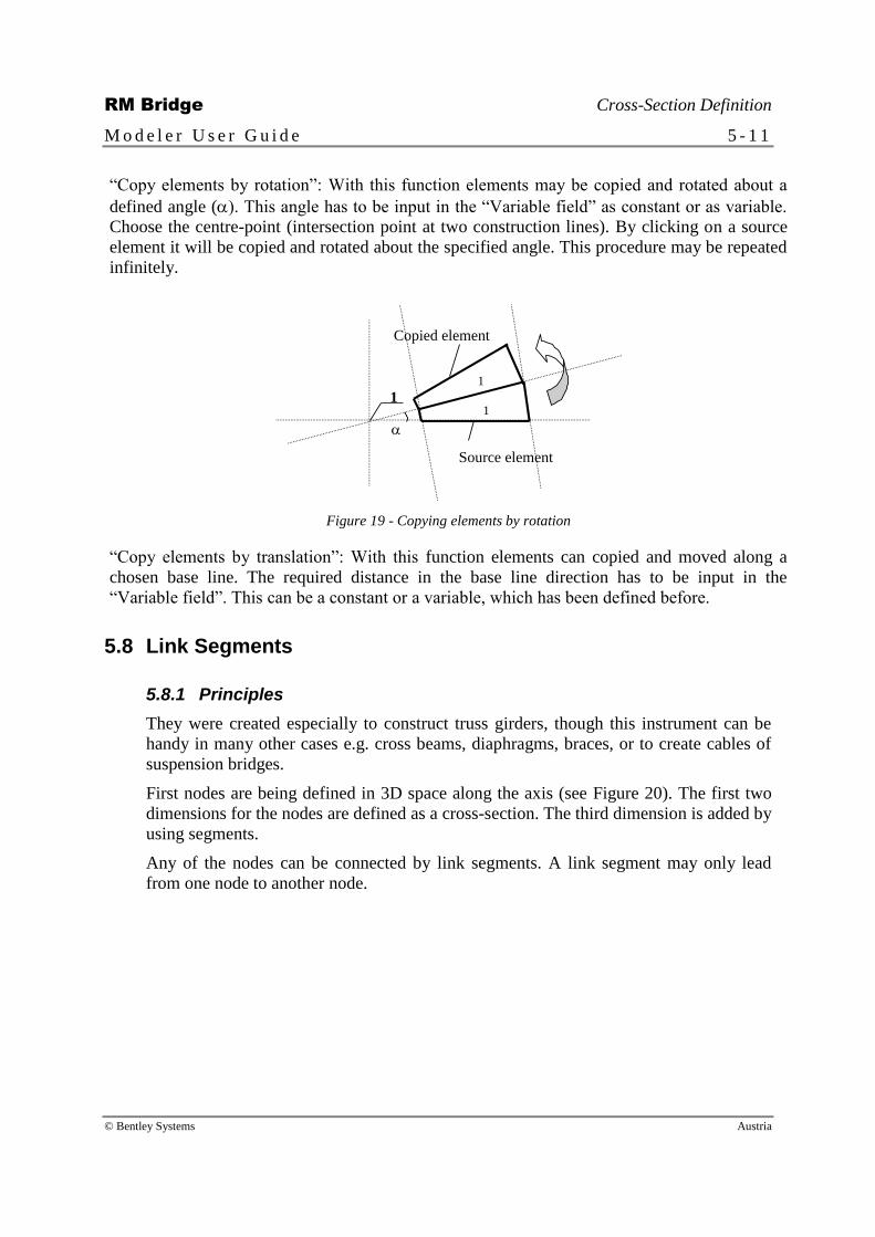
“Copy elements by rotation”: With this function elements may be copied and rotated about a
defined angle (). This angle has to be input in the “Variable field” as constant or as variable.
Choose the centre-point (intersection point at two construction lines). By clicking on a source
element it will be copied and rotated about the specified angle. This procedure may be repeated
infinitely.
1 1
1
Source element
Copied element
Figure 19 - Copying elements by rotation
“Copy elements by translation”: With this function elements can copied and moved along a
chosen base line. The required distance in the base line direction has to be input in the
“Variable field”. This can be a constant or a variable, which has been defined before.
5.8 Link Segments
5.8.1 Principles
They were created especially to construct truss girders, though this instrument can be
handy in many other cases e.g. cross beams, diaphragms, braces, or to create cables of
suspension bridges.
First nodes are being defined in 3D space along the axis (see Figure 20). The first two
dimensions for the nodes are defined as a cross-section. The third dimension is added by
using segments.
Any of the nodes can be connected by link segments. A link segment may only lead
from one node to another node.

RM Bridge Cross-Section Definition
M o d e l e r U s e r G u i d e 5 - 1 2
© Bentley Systems Austria
Figure 20: Truss girder definition with link segments.
It is necessary to define at least two cross-sections: one for the geometrical definition of
the cross-section of e.g. truss girders, and the second to define the cross-section of the
link segment beam. It is possible to define different cross-sections at begin and end of
every “Link segment”.
The cross-sections of the link segments are easily defined as any other girder.
5.8.2 Link Segment Cross-Section
To define the location of the link segments in 3D space you have got to define nodes.
The first two dimensions are added in the cross-section window. This is done by adding
“parts”. Open the parts window by clicking on the arrow beside “Part:” at the bottom of
the cross-section window. Then hit the “insert” icon. Select “Cable” or “Node”,
depending on what you want to create. For truss girders you have to choose “Node”. If
you choose “Cable” the link segments that you create is only able to support tensions.
After that you have got to define which nodes the link segments are connecting.
“Create link”: This is done by choosing this icon at the top of the cross-section screen.
After clicking on two nodes, an input window pops up (You can also double-click on
the same node for link segments along the axis!).
Here you have to input
a name (which you need later in the segment list),
2D location between the created nodes (“Parts”-you have to take care of the order of
your input),
the position of the beams of the link segments (You can change the starting and
ending location by clicking on the button <Change> - the position of the link
segments and the position of the beams can be different!),
and the segment point steps (you can imagine it as the third dimension).
For every location in space you have to create an own link segment.

RM Bridge Cross-Section Definition
M o d e l e r U s e r G u i d e 5 - 1 3
© Bentley Systems Austria
Note: The position of the link segment can be different to the position of the
beam itself.
Further definition for link segments see chapter 7.8, Link Segment.
5.9 Reference Points
The functions in this toolbar facilitate the definition of points within a cross-section.
These points can be used as:
“Reinforcement points” specify the position of conventional reinforcement bars
within the cross-section.
“Stress-check points” provide stress results, which can be requested at a later stage
and can be used for various design checks (e.g. fibre stress check).
“Temperature points” definition for temperature loading definition.
“Connection Points” specify the actual points of contact between segments
(Figure 3).
“Geometry points” for the positioning of internal cables.
Points are grouped together logically. Group names must be assigned in the “Reference
points list”.
5.9.1 Icons
“Reference point at an intersection point”: Intersection points of CL’s can be identified
as reference points in this function.
“Reference point relative to an elements node”: Allows the definition of reference
points in relation to cross-section element nodes. The two offset distances to the node
in X and Y direction (DX, DX) and the types must be specified.
“Reference point relative to element edges”: Two orthogonal distances from two
element edges (DX, DX) give the position of reference points generated by this
function.
“Reference point relative to the center of gravity or the assigned part”: The selected
reference point is always located in the center of gravity of every cross-section along
the axis, even if the cross-section is varying. The center of gravity in X or Y direction
may be selected.
“Reference point with absolute coordinates”: Points can be entered with their co-
ordinates and their types.
5.9.2 Local Mesh Refinement
The local refinement can be used for stress check points. While inserting of modifying
stress check points the “Activate local refinement” may be selected. The element where

RM Bridge Cross-Section Definition
M o d e l e r U s e r G u i d e 5 - 1 4
© Bentley Systems Austria
this point is situated is automatically refined. The refinement depends on where the
stress check point is located in the element – see Figure 21.
If the point is in the centre (point 1) the element is refined like the left element in
Figure 21.
If the point is near to the edge in the centre (point 2) the element is parted like in the
centre.
If it is near to a corner (point 3) the refined mesh looks like in the picture on the
right.
1
2
1
3 2
3
Figure 21 - Local mesh refinement.
If other border elements exist where edges are parted, the neighbouring elements are
refined automatically, corresponding to the prior refined element. In Figure 21 these are
the points 2 and 3. The refinement looks as in the Figure 22.
Figure 22. Mesh refinement – bordering elements.

RM Bridge Cross-Section Definition
M o d e l e r U s e r G u i d e 5 - 1 5
© Bentley Systems Austria
5.10 Dimension Line
“Length dimensioning”: This tool allows a simple definition of dimension lines within
a cross-section. An existing CL as a reference line for the dimension line and two
points between which the distance has to be measured have to be selected. The
dimension is drawn over the first selected dimension line.
“Angle dimensioning”: With this simple angle dimensioning tool it is possible to
measure an angle between two CL’s. The dimension value is drawn along a defined
CL.
5.11 Import and Management of Cross-Sections
“Import cross-section from catalogue”: This button, offered in the “cross management
window” (Figure 23), opens a catalogue with already existing cross-sections (Figure
24). Different types of cross-sections can be selected. The name of the new cross-
section - given by the user - cannot be equal to an existing cross-section name. With the
<Apply> -button the currently chosen cross-section will be copied into the current
project.
Opens the cross-section
catalogue (Import of a
cross section into the
current project) Writes selected cross-
section to the cross-
section catalogue
Import of DXF files
(AutoCAD)
Figure 23 - Cross-section management window
It is recommended to save your own catalogue into a ASCII-file after modifying
it, but don’t use the name gpcata_e.dat (English version) in the
program directory, because this file will be overwritten by an
update or a de-installation of GP. The access to ASCII-
interface of catalogue is possible in the cross-section
management window.
RM Bridge Cross-Section Definition
M o d e l e r U s e r G u i d e 5 - 1 6
© Bentley Systems Austria
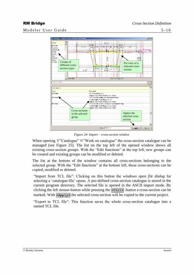
Groups of
different cross-
section types
Pre-view of a
selected cross-
section
Cross-sections
in the selected
group
Applys the
selected cross-
section
Figure 24- Import – cross-section window
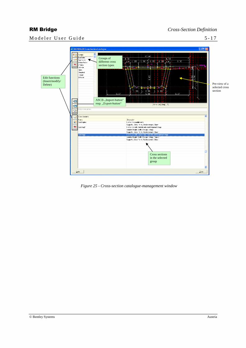
When opening ”Catalogue” ”Work on catalogue” the cross-section catalogue can be
managed (see Figure 25). The list on the top left of the opened window shows all
existing cross-section groups. With the “Edit functions” at the top left, new groups can
be created and existing groups can be modified or deleted.
The list at the bottom of the window contains all cross-sections belonging to the
selected group. With the “Edit functions” at the bottom left, these cross-sections can be
copied, modified or deleted.
“Import from TCL file”: Clicking on this button the windows open file dialog for
selecting a ‘catalogue-file’ opens. A pre-defined cross-section catalogue is stored in the
current program directory. The selected file is opened in the ASCII import mode. By
clicking the left mouse-button while pressing the <Ctrl> -button a cross-section can be
marked. With <Apply> the selected cross-section will be copied to the current project.
“Export to TCL file”: This function saves the whole cross-section catalogue into a
named TCL file.
RM Bridge Cross-Section Definition
M o d e l e r U s e r G u i d e 5 - 1 7
© Bentley Systems Austria
Pre-view of a
selected cross
section
Edit functions
(Insert/modify/
Delete)
ASCII-„Import-button“
resp. „Export-button“
Cross sections
in the selected
group
Groups of
different cross
section types
Figure 25 - Cross-section catalogue-management window
RM Bridge Cross-Section Definition
M o d e l e r U s e r G u i d e 5 - 1 8
© Bentley Systems Austria
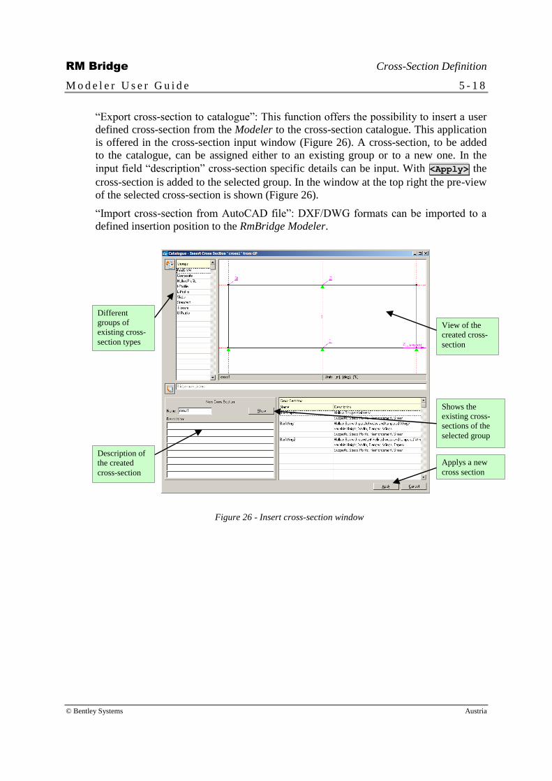
“Export cross-section to catalogue”: This function offers the possibility to insert a user
defined cross-section from the Modeler to the cross-section catalogue. This application
is offered in the cross-section input window (Figure 26). A cross-section, to be added
to the catalogue, can be assigned either to an existing group or to a new one. In the
input field “description” cross-section specific details can be input. With <Apply> the
cross-section is added to the selected group. In the window at the top right the pre-view
of the selected cross-section is shown (Figure 26).
“Import cross-section from AutoCAD file”: DXF/DWG formats can be imported to a
defined insertion position to the RmBridge Modeler.
View of the
created cross-
section
Description of
the created
cross-section
Shows the
existing cross-
sections of the
selected group
Applys a new
cross section
Different
groups of
existing cross-
section types
Figure 26 - Insert cross-section window

RM Bridge Formulas
M o d e l e r U s e r G u i d e 6 - 1
© Bentley Systems Austria
6 Formulas
6.1 Introduction
Certain geometric parameters may vary along an axis in accordance with certain
(mathematical) rules (e.g. variations in the flange depth, distance between two main
girders). These rules, or functions, must be taken into account at three different stages
during the input in the Modeler (Figure 27). Firstly, the variable parts of a cross-section
must be identified as such (see chapter 5.3, Variables and Cross-Section Input).
Secondly, the actual rules must be entered. This is the purpose of the functions
explained in this chapter. And thirdly, the cross-section parameter must be related to
the appropriate mathematical expression, so that the exact position of the variable parts
can be computed as functions of the station along a segment.
constant
constant
constant
fh(s)
Stations – s
fh(s)
s=a s=b
fh(s=a)
fh(s=b)
constant
constant
Figure 27 - Variable flange depth
6.2 Expressions and Tables
The respective variation rules can be entered in two different ways – mathematical
expressions or tables. For the definition of both the following pre-defined functions are
available:

RM Bridge Formulas
M o d e l e r U s e r G u i d e 6 - 2
© Bentley Systems Austria
Station values “sg” (global station), “sl” (local station), “sp” (segment
point number).
Constants “pi” and “e”.
Basic trigonometric functions “cos()”, “sin()”, “tan()”, “acos()”, “asin()”,
“atan()”. Please note that all angles are given in radians!
Basic exponential and logarithmic functions “sqr()”, “ln()”, “log()”,
“exp()” with (exp(2.5) = e2.5
).
Logic functions “abs()”, “min()”, “max”, “hright()”, “hleft()”, “dirac()”,
“diract()”.
abs(a) gives the absolute value of the argument.
min(a,b) gives the smaller value of two arguments.
max(a,b) gives the greater value of two arguments.
hright(a,b) =1 if a>b, else =0
hleft(a,b) =1 if a<b, else =0
dirac(a,b,eps) =1 if b-eps<a<b+eps, else =0 (Figure 28a).
diract(a,b,eps1, eps2) = triangular interpolation (Figure 28b).
(a) 1
0
dirac() eps
a b
(b) 1
0
diract() eps1
a b
eps2
Figure 28 - Logical functions dirac() and diract()
Mathematical expressions can be entered alphanumerically (e.g. x^2/sg+cos(sg-50)). An
internal interpreter converts the expression into station-dependent geometric properties.
In many instances it is more practical to enter the station-dependent information for
certain known points and to interpolate between these points. For these cases, so-called
tables can be generated. Two values need to be entered for each discrete point – the
station (Var A) and the value of the function at this station (Var B). A number of
different interpolation functions are available in the Modeler (constant (Figure 29a),
linear (Figure 29b) and three different parabolic functions (Figure 29c-e)).
Both, mathematical expressions and tables, can reference other functions – both built in
or user-defined at a different point in the formula window. The <i> -button brings up a
graphic representation of the active table. For expression names only use characters a-z,
A-Z in the first position and in addition 0-9 and the symbol ‘_’ thereafter. Do not use
predefined function names.
Note: It is not allowed to use identical names for tables or functions as for
existing names of already defined variables.

RM Bridge Formulas
M o d e l e r U s e r G u i d e 6 - 3
© Bentley Systems Austria
(a)
a
b
(b)
a
b
(c)
a
b (d)
a
b
(e)
a
b
constant linear
parabolic 0 parabolic 1
parabolic 2
Figure 29 - Interpolation functions for tables
6.3 Formula Input Window
Formulas consist of a name for subsequent identification, a mathematical expression, its
actual value, its type and an additional description.

RM Bridge Formulas
M o d e l e r U s e r G u i d e 6 - 4
© Bentley Systems Austria
Mathematical
expressions and
table lists
Table
values Point edit
functions
Table
display
Table Load/Save
functions
Figure 30 - Formula input window.
The “Edit functions” described in chapter 2.6 (icons at the left side of the window) serve
as tools to work on the “Mathematical expressions and tables list”. The “Point edit
functions” provide access to the “Table points” of the active table. An active table can
be displayed on a separate graphic window by clicking on the <i> –button (Figure 30).
With the tools at the bottom of the window, one or several tables may be saved or
existing tables can be loaded. So, modifying and editing tables is easily done in the text
editor.
The actual or all defined tables can be saved to a simple ASCII format by clicking the
button <Save> respectively <Save all tables> . The ASCII files can be edited,
modified and extended. <Load> reads the changed file and updates the listing. Different
input types can be selected. <Load all tables> loads all saved tables and overwrites
the existing ones. This is a very powerful and easy to handle input facility for tables.

RM Bridge Segment Definition
M o d e l e r U s e r G u i d e 7 - 1
© Bentley Systems Austria
7 Segment Definition
7.1 Introduction
Segment information is built from data generated by the functions described in
previous chapters. The geometry of segments in longitudinal direction depends on the
reference line (or axis for master segments) and in orthogonal directions on the shape
of the cross-section. All geometry definitions may be given in terms of formulas.
Segment points govern the degree of structural discretization within segments. The
structural system for RmBridge, which will be generated from the Modeler data, will
have a structural node at each segment point and structural elements between the
respective consecutive nodes.
Please note that a segment and an axis must be activated in the “Segment management
window” and the “Axis management window”.
Segment
point list
Active segment
point details -
before
Active
segment
point details -
after
Select active
segment
point details
Figure 31 - Segment definition input window
RM Bridge Segment Definition
M o d e l e r U s e r G u i d e 7 - 2
© Bentley Systems Austria
The following segment types are available in the RmBridge Modeler:
Main Girder
Pier
Cable
Free Pier
Cross Member
RM Bridge Segment Definition
M o d e l e r U s e r G u i d e 7 - 3
© Bentley Systems Austria
7.2 Further Functions in the “Segment Management Window”
“Toggle segment point/element view”: Switch between segment point and element
view. In segment point view the start and the end points of segments are shown
(=connection between segments), whereas in element view only the elements
(segments) can be changed.
“Move segment points”: To move segment points, mark one line in the segment list and
hit the “Move segment points” button. All the following segments to the end will be
selected. As “Station difference” enter a value for the displacement of the segments.
This displacement must not exceed the previous segment.
“Fast recalculation”: This button produces updated data if cross-sections have been
modified after they having been assigned to segment points previously. All cross-
section inputs have to be marked by an „OK“ in the segment point list.
“Recalculation with formula evaluation”: In contrast to the button “Recalculate”, all
variable values are calculated by evaluating the formula expressions.
“Show coordinates”: Shows the co-ordinates of the existing segment points.
“Show graph”: The existing FE cross-sections of the active segment can be displayed
by using this button (including formula evaluation).
<Connection> “Connection”: Defines connections between segments or
between a segment and a rigid support point (see chapter 7.2.1,
Connections).
<New “sg”-table>
“New “sg”-table”: This function is used to define tables with
the functions “sg”, “sl” and “sp” (station dependent functions),
which will be assigned to the segment points. The function “sg”
returns the global station at the segment point. The function “sl”
returns the local station at the segment point. Local means that
the station at the 1st segment point is 0.0 and the station of all
following points are related to the first one. The function “sp”
returns the number of the segment point.
<Points by Ref.-Segment>
“Points by reference segment”: Segment points related to points
of a reference segment can be defined. To each reference point,
a point in the current segment will be searched, where their
distance line is positioned normal to the axis of the current
segment. Optionally, two different tables may be built and
stored in files that consists of the distances between the points
and the angles between the cross-sections at the points,
respectively.
“Segment point details”: Switch between variable view
(variable definition) and parts view (material, numbering and
group definition).
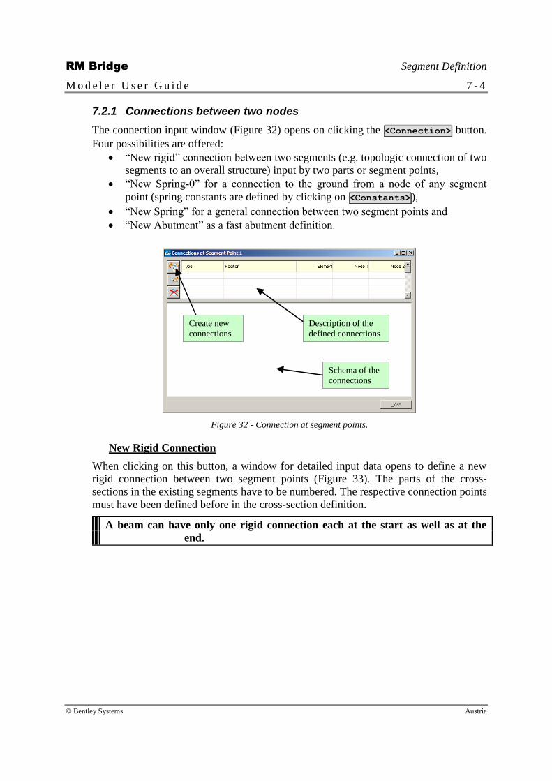
RM Bridge Segment Definition
M o d e l e r U s e r G u i d e 7 - 4
© Bentley Systems Austria
7.2.1 Connections between two nodes
The connection input window (Figure 32) opens on clicking the <Connection> button.
Four possibilities are offered:
“New rigid” connection between two segments (e.g. topologic connection of two
segments to an overall structure) input by two parts or segment points,
“New Spring-0” for a connection to the ground from a node of any segment
point (spring constants are defined by clicking on <Constants>),
“New Spring” for a general connection between two segment points and
“New Abutment” as a fast abutment definition.
Description of the
defined connections
Create new
connections
Schema of the
connections
Figure 32 - Connection at segment points.
New Rigid Connection
When clicking on this button, a window for detailed input data opens to define a new
rigid connection between two segment points (Figure 33). The parts of the cross-
sections in the existing segments have to be numbered. The respective connection points
must have been defined before in the cross-section definition.
A beam can have only one rigid connection each at the start as well as at the
end.

RM Bridge Segment Definition
M o d e l e r U s e r G u i d e 7 - 5
© Bentley Systems Austria
First segment point
Connection-part of
the segment-point
2nd
connection-point
(segment, part)
Figure 33 - Rigid connection between two segment points
New Spring-0
With this function a spring element between an existing connection point (reference
point) of a cross-section and the “earth” (node 0) can be defined. Springs of this type
can be connected to a structural node of any segment point. The element number, the
spring constants and the direction of the spring have to be specified using the button
<Constants> in the input window shown in Figure 34.
Select a segment-
point for the
connection
Select a
defined
connection-
point
Selection if nodes
should be defined
by parts or by free
node number
Define the
constants of
the springs
Figure 34 - Spring to node 0 (rigid base)
New Spring
This function opens a window where springs between two connection points in the
cross-section can be defined. At least one node of a spring element has to be connected
to a structural node. The other node can be situated at a connection point anywhere

RM Bridge Segment Definition
M o d e l e r U s e r G u i d e 7 - 6
© Bentley Systems Austria
within the cross-section. The element number, the spring constants and the direction of
the spring have to be specified using the button <Constants> in this input window.
Select the segment-
points of the 2-node-
spring
Select the
connection-
points
Select a segment
for the spring
connection
Define the
constants
Figure 35 - Spring between two nodes
New Abutment
The RmBridge Modeler provides the possibility of a quick and easy abutment definition
(standard abutment with 2 bearings).
Figure 36 - Abutment definition for a hollow box bridge
In most cases the Modeler automatically recognises the corresponding connection
points depending on the position of the segment. It is just necessary to enter the element
numbers of the springs, modify the spring constants, if necessary, and enter the node

RM Bridge Segment Definition
M o d e l e r U s e r G u i d e 7 - 7
© Bentley Systems Austria
number where the spring-0 should be connected to. For conventional input see chapter
0.0.0.
7.2.2 Modelling Supports with Spring Elements
Supports with a discrete stiffness can be defined by using spring elements. The local
orientation of these springs in comparison to the global coordinate system of RmBridge
is shown in Figure 37. The Modeler automatically creates the local coordinate system of
these spring elements, taking into account the plan angle α2 of the superstructure
elements the spring is connected to. The local axis xL of the springs is always oriented
in the global YG direction, i.e. the elevation angle α1 will be set to 90°. The plan angle
α2 will always be zero. The angle β will be created as the angle between the global X-
axis and the tangent to the horizontal projection of the respective superstructure axis.
XG XG
2=0°
1=90°
=90° I
xL yL
zL
ZG
YG
K
YG
ZG
=0°
xL
yL zL
I
K
2=0°
1=90°
Figure 37 - Orientation of spring elements, for the final RM “Left Hand System”
Figure 37 shows the generated axis system for superstructure axes in global x (β = 0)
and z (β=90°) directions. To achieve a consistent logical model of the support spring,
the axis, the cross-sections of girder elements, the segment numbering and assignment,
and the part numbering and assignment must have been defined before.
Note that any angle β directly defined by the user will be added to the default
angle derived from the superstructure axis direction, i.e. angles entered by the
user represent the angle between the superstructure axis direction and the main
principal inertia plane of the pier or bearing modeled by the spring.
Simple Supports connected to a Structural Node
Using the <Connection> -button in the „Segment input-window“ allows for creating a
support by selecting „New Spring-0“. This spring element connects the node “0” (rigid
base) with the defined connection point (“CP0”) of the cross-section at the specified

RM Bridge Segment Definition
M o d e l e r U s e r G u i d e 7 - 8
© Bentley Systems Austria
segment point. By using the <Constants> -button the stiffness of the spring element
can be modified. It must be carefully checked if any rotational stiffness term (CMY,
CMY, CMZ) must be entered in order to avoid torsion freedom of the connected
superstructure.
Be careful when defining the stiffness because of the local co-ordinate system
(Xlocal, Ylocal, Zlocal) differing from the global system (see 7.2.2).
The structural length of spring elements is zero per definition with a length of zero. An
appropriate eccentric connection from the connection point “CP0” to the structural node
is generated automatically in the Modeler.
Structural node 101
“CP0”
CP0“ Spring “0”
Spring-element 1101
Co-ordinate -system
structure (global)
Co-ordinate -system
spring (local)
AXIS
1
Yglobal
Zglobal
Xglobal
Xlocal
Zlocal Ylocal
CMX
CMY
CMZ
Figure 38 - Simple support and connection to the structural node
Definition of a simply supported Pier
First, a new segment (slave segment) and a cross-section for the pier have to be defined.
In the “Segment list window” (Figure 8) the name of the segment and the type of the
segment “Pier” have to be entered. The default for the direction of the cross-section of
the pier is exactly horizontal. By entering an angle a rotation of the pier about the
vertical axis can be defined. With the input of the reference-segment and one connection
point, the position of the pier is exactly defined in relation to the main girder. In the
“Segment point list” (Figure 31) the height of the pier and the segment points, which
govern the degree of structural discretization within the segment can be entered (the
height 0.00 m should be defined at the top of the pier).
The master-segment and the slave-segment have to be connected. This function is
offered in the “Segment input-window” of the “pier segment”. By using the button
<Connection> a “New spring” between the two segments can be created. The input
terms are the two segments (seg1, seg2) to be connected, the corresponding segment
points and the parts of the cross-sections as well as the number of the element (1105).

RM Bridge Segment Definition
M o d e l e r U s e r G u i d e 7 - 9
© Bentley Systems Austria
Also the position of the element and the connection points belonging to them (“CP0”,
“CP1”) are requested in this input window (Figure 39).
The connection from the pier to the “earth” will be defined as a support spring (“New
spring-0”) (see chapter 0.0.0).
Co-ordinate -system
structure (global)
Co-ordinate -system
spring (local)
Length of zero
Spring-element 1105
node 1105
node 101
Support-spring 1100
“CP0“
+0,00
(spring – “0”)
seg1 (master-segment)
seg2 (slave-segment)
“CP1“
Yglobal
Zglobal
Xglobal
Xlocal
Zlocal Ylocal
CMX
CMY
CMZ
Figure 39 - Pier support definition
Multiple Bearing/Spring Support Definition
A predefined input window of the following definition is described in chapter 0.0.0.
First, the required connection points (called in the following “CP0”, “CP1” and “CP2”)
have to be defined in the “cross-section window” (see chapter 5.9). The connection to
the “earth” will be created with a “New spring-0” over the <Connection> -button in the
“Segment input-window”. After the input of the segment points, the element number,
the connection point and the “Free node number”, (1100) the spring can be generated
(The connection to “Node 0” will be created automatically.). The input of “free node
number” is necessary because otherwise the connection from “CP0” would be created
directly to the structural node (101) (see chapter 0.0.0).
By clicking on the <Constants> -button the corresponding stiffness of the spring
(KN/m) as well as a deviation from the direction of the local co-ordinate system can be
entered and modified.
The connection to the structural node (101) will be defined eccentrically with two
spring elements created as “New springs”. In the input window the segments, the
segment points, the start node (1100), the element number (1101, 1102) as well as their
element position (“CP1”, “CP2”) have to be entered (see Figure 40).
The structural interpretation of this input sequence is an eccentric connection between
node 1100 and node 101. The stiffness of the two piers will be regulated by the spring
constants of the spring elements situated in “CP1” and “CP2”.

RM Bridge Segment Definition
M o d e l e r U s e r G u i d e 7 - 1 0
© Bentley Systems Austria
spring 101
“CP0”
(spring 1100)
“CP2” “CP1”
Co-ordinate -system
structure (global)
Co-ordinate -system
spring (local)
AXIS 1
(spring-element 1101)
Spring-element 1100
Yglobal
Zglobal
Xglobal
Xlocal
Zlocal Ylocal
CMX
CMY
CMZ
Node “0”
(spring-element 1102)
Figure 40 - Multiple spring supports
7.2.3 Cross members
Cross members are needed for the simulation of transverse structural behaviour of
roadway slabs (double T-beams, multiple box-sections….). Two examples are shown in
Figure 41 - Examples for cross-member definitions.
Part 1
Cross-member element Cross-member elements
Part 2 Part 1 Part 2 Part 3 Part 4
Figure 41 - Examples for cross-member definitions
For a reasonable cross-member definition a minimum of two parts must be
defined to be connected by cross-members.
Where cross members need to be positioned between two main girders, connection
points have to be defined in the respective cross-sections (see chapter 5.9).
New cross members are constructed like any segment by inserting a new segment and
define as segment type “Cross member”. First, all parameters of one cross member
segment is defined and after that it may be copied (see chapter 7.3).
The geometry of a cross member is defined by its connection points and the associated
parts of the cross-section (Figure 41 - Examples for cross-member definitions).

RM Bridge Segment Definition
M o d e l e r U s e r G u i d e 7 - 1 1
© Bentley Systems Austria
Details about the material as well as the cross-section of the cross member can be
defined in the pop-up window after pressing <Additional Parameters> .
Assignment of cross-sections to the cross-members
7.2.3..1 Generating tables for b1 and b2
Already defined tables can be assigned to the width of the reference cross-section. If the
main-girder elements have different element lengths, with this feature the cross-sections
for the cross-members can be created with the corresponding width (the width of the
cross members varies with the element length of the main-girder).
This requires that the reference cross-section be created with the variable
dimensions b1 and b2 (see Figure 42).
7.2.3..2 Use of the function _hdp (half distance between two segment points)
The width of cross-sections (b1, b2) depends on the adjacent element lengths before and
after segment points of the main-girder (b1=L1/2, b2=L2/2) (see also chapter 0.0.0).
Instead of assigning tables with the corresponding width of the cross section, there is
also the possibility to assign the function _hdp(-1) and _hdp(1). When using these
functions, the program automatically calculates the width of the cross-sections from the
adjacent half girder element length for generating the appropriate cross-sections. The
expression _hdp(-1) delivers the half element length “before the segment point” and
_hdp(1) the adjacent half element length “after the segment point”. This expression can
be combined also with formulas and other expressions.
Note, that for arranging the cross-sections at the correct position, the
eccentricity check boxes (Y, Z) have to be clicked in the input field of the cross-
member definition.
Figure 42 - Variable defined reference cross section
Comments on eccentricities in Y and Z-direction
The following example shows a general view of a double T-beam. The plotted cuboids
represent a cross-member element, which is connected at two defined connection points
between two series of longitudinal girders.

RM Bridge Segment Definition
M o d e l e r U s e r G u i d e 7 - 1 2
© Bentley Systems Austria
Figure 43 - General view of a double T-beam
Cross-section arrangement in longitudinal direction (plan view):
Figure 44 - Plan view of cross members cross-sections
Li Element length
bi Half element length (bi=Li/2)

RM Bridge Segment Definition
M o d e l e r U s e r G u i d e 7 - 1 3
© Bentley Systems Austria
Created Cross-section of the Cross-member:
Figure 45 - Cross-section of the cross-member
Note that in the Modeler GUI cross-sections are generally presented as views
against the axis direction. In order to define the eccentric position of cross-
member elements properly, they must usually be oriented from the right main
girder to the left main girder, e.g. from axis 2 axis 1 as shown in Figure 43 -
General view of a double T-beam).
Position of the cross-section of the cross-member without consideration of the
eccentricities:
Figure 46 - Cross-section without eccentricities
This means that the drawn cross-section (see Figure 45) will be input at the specified
connection points in the middle of the upper edge of the cross-section with b1=b2
=(L1+L2)/2.
Position of the cross-section of the cross-member with consideration of the Z-
eccentricity:
Figure 47 - Cross-section considering the Z-eccentricity

RM Bridge Segment Definition
M o d e l e r U s e r G u i d e 7 - 1 4
© Bentley Systems Austria
The cross-section of the cross-member will be inserted according to the defined
geometry in z-direction and in y-direction at the upper edge of the cross-section.
Position of the cross-section considering both eccentricities (Y, Z):
In this case the cross-section will be inserted according to the defined cross-section (see
above Figure 45) at the specified connection point.
7.3 Copying Segments or Sequences
The RmBridge Modeler offers the possibility to copy complete segments in a simple
way (e.g. pier segments, longitudinal girders, etc) and to insert them at a desired
position. It is also possible to copy segment parts within a segment, allowing for an
efficient definition of the complete segment.
7.3.1 Copying Complete Segments
In the “Segment input window” this function offers the possibility to copy complete
segments and to insert them at a desired position. At first, the segment to be copied has
to be marked. By clicking on the “Copy” function in the “Edit-toolbar” the segment will
be duplicated. The opened input window “Copy Segment” allows for specifying the
position of the copied part exactly.
All definitions in this segment will be copied. The segment may be introduced by
the user individually. Afterwards, the user can modify the attributes.
7.3.2 Copying Sequences of a Segment
With this function specified, sections (sequences) of a segment can be copied. The
advantage of this feature is that recurrent identical sections can be copied and must not
to be recreated.
The section of the segment to be copied can be marked by clicking the first and the last
line of the desired section with the left mouse button and the pressed key <Ctrl>
simultaneously. The marked lines change to highlighted red.
Afterwards click on the “Copy” function in the “Edit-toolbar” and the information
window, which is shown in the lower picture (Figure 48.) is displayed. There you can
check if the chosen section of the segment is the desired one and after clicking <OK> the
sequence of the segment is copied subsequent after the cursor position (dotted line).
All definitions in the copied section, used cross-sections, attachment pier segments and
support definitions are taken along.

RM Bridge Segment Definition
M o d e l e r U s e r G u i d e 7 - 1 5
© Bentley Systems Austria
Figure 48 - Copying sequences of a segment
The numbering of copied elements and spring elements has to be assigned
afterwards by editing subsequently. This guarantees that the user can create the
numbering in accordance with his personal ideas.

RM Bridge Segment Definition
M o d e l e r U s e r G u i d e 7 - 1 6
© Bentley Systems Austria
7.4 Existing FE-Cross-Sections at the Segment Points
All segment points of the active segment are shown in this list. It can be manipulated
with the general edit functions described in chapter 2.6. New points can be added and
existing points modified or deleted. For each segment point several pieces of
information need to be entered:
The cross-sections immediately to the left and immediately to the right of the section
point
Parameter “DCROSS” (transversal shift of the cross-section at the section point)
Parameter “DVERT” (vertical shift of the cross-section at the section point)
Parameter “DA” (rotation angle about the segment reference line)
Parameter “DB” (rotation angle about the horizontal cross-section axis)
This segment point specific information can be edited in the input window shown in
Figure 49 for one or more segment points.
Figure 49 - “Modify segment point” input window
7.5 Active Segment Point Details
If variables have been used during the definition of a cross-section, then these variable
parameters have to be coupled with formulas to enable the station-dependent
computation of cross-section geometries. These specifications are made for each side
(left and right) for each segment point.
The assignment of tables to the respective segment-points takes place in the “variable-
list” after the “segment-input window” has been opened (the radio-button “variables
must be activated). By double-clicking a line of the variable lists or by pressing the

RM Bridge Segment Definition
M o d e l e r U s e r G u i d e 7 - 1 7
© Bentley Systems Austria
symbol “Modify” on the left side of the variable lists, the input window for the
assignment of expressions opens. By clicking on the desired line and pressing the key
<Ctrl> simultaneously (the marked line is highlighted with red color) a new “value” or
“table” can be assigned in the input field “expression” directly or selectively by clicking
on the arrow-button. To copy variables from begin to the end of the segment or vice
versa (left table to the right), select the desired lines of the table and copy the desired
expressions from the one table to the other by hitting the <All> or the < > key.
Note that if you change tables or formulas, you have to reassign these tables or
formulas to the specified variables.
7.6 Stay cable input
It is very easy to build up the whole model of a stayed cable bridge using the RmBridge
Modeler. In addition to the already discussed topics for modeling the main girder and
piers, the user has to define the stay cables. For each stay cable an additional segment
using the segment type “Cable” has to be created. Connection points at the
corresponding cross sections where the cables shall be connected have to be predefined.
The cable creating steps are the same as with cross members, described in chapter 7.2.3.
7.7 Segment Type „Free Pier“
The segment type “Pier” needs an absolute connection to a segment type “Main Girder”.
Which means: no “pier segment” if there is no “Main girder segment”.
Since it might be reasonable to generate a pier on its own without going through a main
girder segment definition, the “Free Pier” can be defined as well.
The segment type “Free Pier” needs no connection to an existing segment but the
definition of free points in the point management window (name, x-,y-,z-coordinates) to
define the geometrical definition. These free points have to be selected when defining
the new segment using the type “Free Pier”.
7.8 Link Segments
To prepare the cross-sections for the link segment definition see chapter 5.8, Link
Segments.
You have to add one segment in the segment list to define the main girder (which is
shown in the segment list window as <Base Segment>).
Open the segment point list of the girder and part it in so many segments, that you can
define all the nodes of the main (truss) girder (you have to adjust that definition with the
link segment definition in the cross-section window).
To define the link segments corresponding to the main girder, press <Link Segments>
“Create Link Segment” at the top of the segment list window.

RM Bridge Segment Definition
M o d e l e r U s e r G u i d e 7 - 1 8
© Bentley Systems Austria
In the popup window you input
the link segment name defined in the cross-section window,
the points and positions where this link segment shall be created,
the activation or deactivation of the link segment (when deactivated, link segments
will not be calculated),
the position of the link segments - at the begin or at the end of the segment,
the cross-sections of the link segment beams,
the link segment cross-section plane (normal to cross-section, vertical and horizontal
in elevation),
and you can insert hinges.
Note: It’s very useful to control the connections of the link segments with the
‘3D view’ window while creating them.
After that, you choose ‘ Parts’ and hit the ‘Edit’ icon on the left side of the segment
list window.
Here you apply a group, a material and a numbering of the link segment beams (They
are named ‘B’ plus the chosen number).
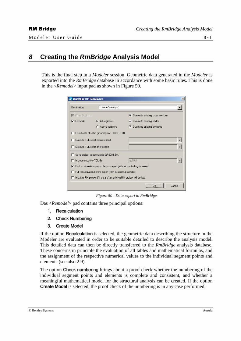
RM Bridge Creating the RmBridge Analysis Model
M o d e l e r U s e r G u i d e 8 - 1
© Bentley Systems Austria
8 Creating the RmBridge Analysis Model
This is the final step in a Modeler session. Geometric data generated in the Modeler is
exported into the RmBridge database in accordance with some basic rules. This is done
in the <Remodel> input pad as shown in Figure 50.
Figure 50 - Data export to RmBridge
Das <Remodel> pad contains three principal options:
1. Recalculation
2. Check Numbering
3. Create Model
If the option Recalculation is selected, the geometric data describing the structure in the
Modeler are evaluated in order to be suitable detailed to describe the analysis model.
This detailed data can then be directly transferred to the RmBridge analysis database.
These concerns in principle the evaluation of all tables and mathematical formulas, and
the assignment of the respective numerical values to the individual segment points and
elements (see also 2.9).
The option Check numbering brings about a proof check whether the numbering of the
individual segment points and elements is complete and consistent, and whether a
meaningful mathematical model for the structural analysis can be created. If the option
Create Model is selected, the proof check of the numbering is in any case performed.

RM Bridge Creating the RmBridge Analysis Model
M o d e l e r U s e r G u i d e 8 - 2
© Bentley Systems Austria
If the option Create Model is selected, the data of the analysis model are created and
stored in the RmBridge analysis database. Additional options govern, whether the
existing RmBridge analysis database shall be initialized before inserting the Modeler
data, or whether the new data only replace those data of the analysis database, which
have been defined in the Modeler database.
Other additional options can be set in the <Options> menu. They allow for the data of
different object categories (cross-sections, segments, etc) to be excluded or included in
the transfer process.
This <Options> menu also governs the storage of backup files for saving the current
status of the Modeler database. These backup files are TCL files in ASCII format.
Different export possibilities are available.


