River Bank Foundation - University of Minnesota
38
MIPSYCON 2016 Luke Karels and Duane Phillips Stanley Consultants, Inc. River Bank Foundation Design
Transcript of River Bank Foundation - University of Minnesota

MIPSYCON 2016
Luke Karels and Duane PhillipsStanley Consultants, Inc.
River Bank Foundation Design

Objective and Basis
• Presentation of design and construction considerations for river bank and river crossing foundations on transmission line projects.
• Topics Covered• Loading• Structure Types• Design Process and Alternatives• Constructability and Construction Methodology
• Project Examples: • 2,700‐foot crossing of Missouri River• Multiple crossings of Minnesota River

Examples ‐ Foundations

Basic Foundation Design

Loading Factors
Significantly higher load due to wire
selection (strength) and tension.
Resulting ground line moments significantly
higher.
Total loading may result in alternative
designs.

Loading Considerations
• Guyed vs. self‐supporting• Deadend vs. tangent• Required additions• Markings, lighting, maintenance, underbuild
• Geotechnical (soils/rock)• Environmental concerns• Water flow, flooding, debris, wildlife

• Conductor point loads
• Pole self‐weight
• Wind loads• Wind on pole
• Wind on wire
• Ice loads
• Hardware
• Maintenance/construction loads• Stringing loads
Pole Loads ‐General
Conductor Resultant Load
• Conductor weight, ice, and wind combined
Ice
WindWind H Load
Ice V Load
Conductor V Load
NESC with “K” Overload Factor
Resultant Actual Load

Structure Types
Monopoles

Structure Types
Multi‐Pole Structures

Structure Types
Lattice Structures

Structure Loads
Transverse and longitudinal load due to conductor tension
• Changes in line direction• Span length variation• Unbalanced ice• Broken wires• Dynamic loads

• Single Pole w/o Guys (self‐supporting)• Large overturning
moment (M)
• Relatively small horizontal load (H)
• Vertical load (V) driven by structure/foundation weight and wire
• Typically use drilled piers, driven steel caissons
Foundation Design Process

Foundation Design Process
Lattice tower w/o guys
• Small base moment• Relatively small shear load• Large vertical load, downward or upward• Typically use caissons, spread footings, or driven piles

• Borings taken at each pole location:• Identify cobbles, boulders or
other obstructions
• Drivability a concern
• Soil profile:• Low blow counts
• Soft organic swamp deposits (organic clay, organic silt, peat)
• Loose alluvial deposits (loose silty sand, silt)
• Glacial till (stiff sandy lean clay, stiff clayey sand)
Subsurface Conditions

River Crossing Challenges
• Potential challenges include:• Dynamic terrain changes• Unique structure loading• Poor soil conditions• Unfavorable construction
access• Environmental restrictions
• Must use communication and collaboration to overcome challenges• Engineers, owners, and
contractors must work together

Design Alternatives

Alternatives
Considerations:
• Cost• Material availability• Procurement schedule• Hauling requirements• Required construction equipment• Access requirements• Maintenance requirements
Traditional Drilled Piers
• Deep, permanent casing, spoils, many concrete trucks (access)
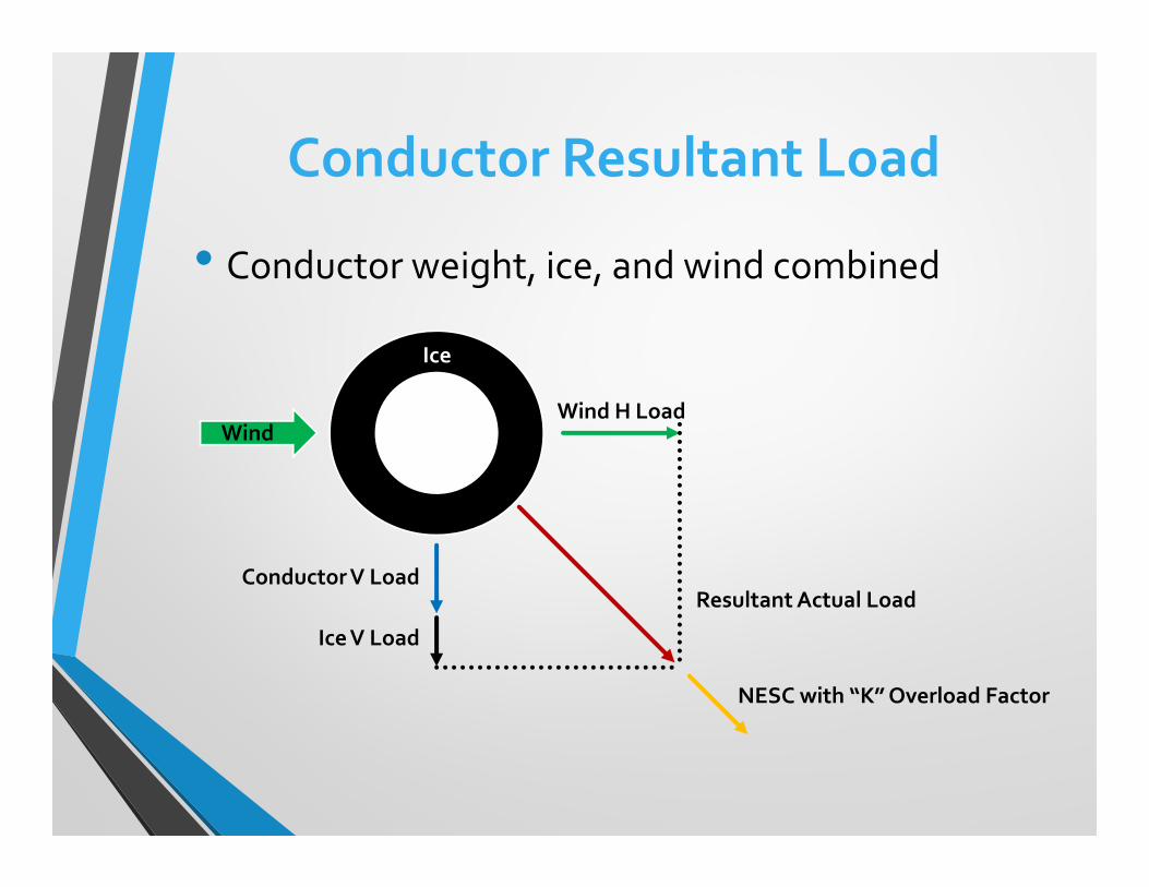
Vibratory Caissons
• Eliminate need for large amounts of concrete
• Minimal equipment needed
• Requires soils conducive to vibratory installation
• Concrete, pad excavation with high water table
Driven Piles with Pile Cap

Drilled Pier with Casing

Drilled Pier with Casing

Driven Pile with Pile Cap

Micropiles
Vibratory Caisson “Socket” Connection

Vibratory Caisson

Design Considerations

Typical Long Span Concepts
• Tension vs. Height• ↑Tension →↑ Load and ↑Galloping• ↓Tension →↑ Sag →↑Height
• Tangent vs. Deadend• Typically trade height for load and type

Operational Considerations
Terrain → access for construction and maintenance
Additional Support → lighting, supplemental power
Ground → geotech, grounding, ground water, flood plains
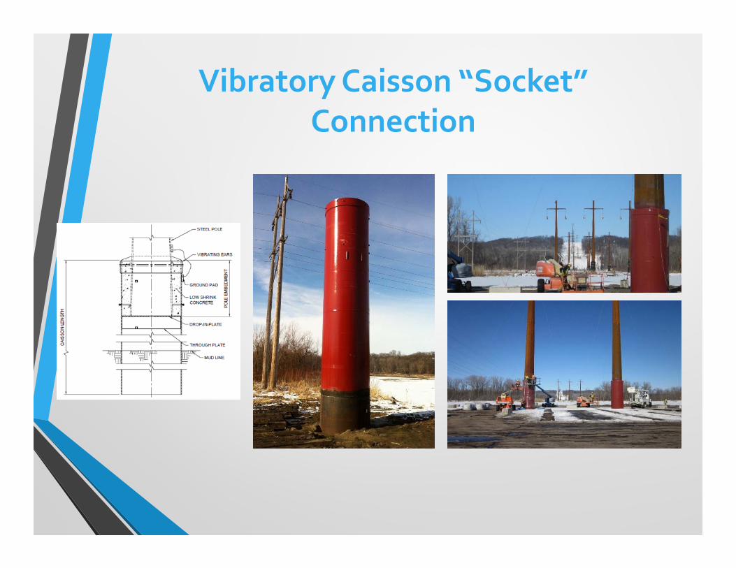
Flowing Water → flood plains, debris damage, erosion

Flood Plain Factors
Height of foundation vs. flood plain levels
Loading from flowing water and ice
Loading from floating debris
Soil erosion from water flow
Soil bearing and skin friction assumptions

100‐Year Flood Levels
Riverbank Erosion Example

Riverbank Erosion Example

Riverbank Erosion Example

Constructability

Site Conditions
Space Availability →Can we build there?
Site Access →Can we get there?
Weather→When can we gain access and for how long?Environmental →Are there any environmental limitations to accessibility?Maintenance→When do we need to get there in the future? How will we get there (once contractor is long gone)?

Installation Factors
Site access for materials and equipment
Limitations to construction sequence for installation
Locations to set‐up construction equipment
Environmental factors that would limit construction
Scheduling and coordination concerns
Construction Methods
Experience and expertise of contractors
Detailed review of methods (and alternatives) and expectations
Site access requirement reviews
Review of equipment to be used during installation
Observation with design support during installation

Collaborate with all partiesThoughtful planning Dynamic communication Efficient execution
Conduct thorough data collectionKnow what you are dealing with Study various alternatives Identify all possible obstacles
Define project constraintsScope/budget/schedule
Create sub‐project to enhance focus
Keys to Success

Luke Karels and Duane PhillipsStanley Consultants, Inc.
River Bank Foundation Design
QUESTIONS?