Ritter Contact D720 - Welcome to Ritter Dental Australia Contact H User Manual.pdf · Wiring...
86
Ritter Contact D720 Dental Work Place - Operating Instructions - Maintenance Instructions - Mounting Instructions J-1136EN, V.02.02.03 Ritter Concept GmbH Bahnhofstraße 65, 08297 Zwönitz Fon: 037754/13-0, Fax: 037754/13-342 e-mail: [email protected] Internet: http://www.ritterconcept.de
Transcript of Ritter Contact D720 - Welcome to Ritter Dental Australia Contact H User Manual.pdf · Wiring...

Ritter Contact D720
Dental Work Place- Operating Instructions- Maintenance Instructions- Mounting Instructions
J-1136EN, V.02.02.03
Ritter Concept GmbHBahnhofstraße 65, 08297 Zwönitz
Fon: 037754/13-0, Fax: 037754/13-342
e-mail: [email protected]: http://www.ritterconcept.de

ForewordContact D720
J-1136EN, V.02.02.03 3
Dear User,
Congratulations for choosing your new Ritterequipment and thank you very much for yourconfidence!
This modern equipment was produced to thehighest standards by our development andproduction engineers.
You and your staff will get real benefit and advan-tages out of your new Ritter equipment when youadhere to the technical and operating instruc-tions given during the demonstration while theequipment was put into operation at yoursurgery.
During daily practice, one or the other questionmay arise which will be answered by our opera-ting instructions.
For easy operating, consideration of technicalaspects and legal regulations and observation ofthe maintenance instructions, we recommendthat you and your staff study this manual verycarefully.
In case of technical problems - call our servicehotline phone 00 49 (0)37754 / 13-290.
And now enjoy your Ritter equipment!

Contact D720
J-1136EN, V.02.02.03 5
Table of Contents
MAINTENANCE INSTRUCTIONS
Contents 67
Daily 69
Weekly 73
Quarterly 75
Cleaning 84
Failure codes 85
MOUNTING INSTRUCTIONS
Contents 89
Transport of the unit column 91
Transport of the patient chair 92
Mounting 93
How to open the unit column 94
Mounting plan Contact D720 95
Mounting of the instrument carrier 97
Installation plan 99
Valve block 101
Air and water plan (WES D628) 103
Air and water plan Contact 105
Wiring diagram 107
Technical Data 6
Table of dimensions 7
General instructions 8
OPERATING INSTRUCTIONS Dentist's Unit
Table of content 13
Description 15
Order of instruments, instrumentation 16
Operation, burr change 17
Control elements 18
Control elements, foot panel 20
Control elements, 4-pedal foot controller 21
Programming the instruments 22
Instruments, Special functions of the foot panel 23
Air turbine 24
Micromotor 25
Ultrasonic scaler: ZEG 27
Topjet six-function syringe 29
Electro-surgical unit: Elektrotom 190 30
X-ray viewer 32
Dental operating light 33
OPERATING INSTRUCTIONS Patient Chair
Contents 37
Description 39
Working Area 40
Operation 41
Control elements, manual control 42
Program control, programming the chair positions 43
Safety stops 44
Head supports, handgrip 45
OPERATING INSTRUCTIONS Assistant's Unit
Contents 49
Description 51
Working area 52
Control elements 53
Cup filling 54
Bowl flush 55
Saliva ejector, surgical suction 56
Suction handpiece 57
Topjet six-function syringe 58
Curing light: Lysta 59
Hydrocolloid quick connection 60
Hygiene System H1 61
Amalgam Separator MST 1 62
Water Disinfection System WES D628 63
Valve for bowl rinse 64
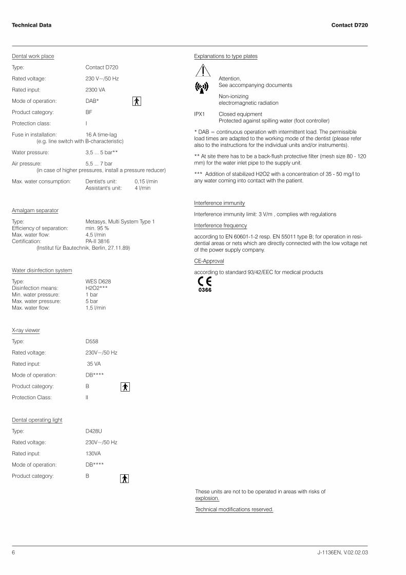
Dental work place
Type: Contact D720
Rated voltage: 230 V~/50 Hz
Rated input: 2300 VA
Mode of operation: DAB*
Product category: BF
Protection class: I
Fuse in installation: 16 A time-lag(e.g. line switch with B-characteristic)
Water pressure: 3,5 ... 5 bar**
Air pressure: 5,5 ... 7 bar(in case of higher pressures, install a pressure reducer)
Max. water consumption: Dentist's unit: 0,15 l/minAssistant's unit: 4 l/min
Amalgam separator
Type: Metasys, Multi System Type 1Efficiency of separation: min. 95 %Max. water flow: 4,5 l/minCertification: PA-II 3816
(Institut für Bautechnik, Berlin, 27.11.89)
Water disinfection system
Type: WES D628Disinfection means: H2O2***Min. water pressure: 1 barMax. water pressure: 5 barMax. water flow: 1,5 l/min
X-ray viewer
Type: D558
Rated voltage: 230V~/50 Hz
Rated input: 35 VA
Mode of operation: DB****
Product category: B
Protection Class: II
Dental operating light
Type: D428U
Rated voltage: 230V~/50 Hz
Rated input: 130VA
Mode of operation: DB****
Product category: B
Contact D720
6 J-1136EN, V.02.02.03
Technical Data
Explanations to type plates
Attention,See accompanying documents
Non-ionizingelectromagnetic radiation
IPX1 Closed equipmentProtected against spilling water (foot controller)
* DAB = continuous operation with intermittent load. The permissibleload times are adapted to the working mode of the dentist (please referalso to the instructions for the individual units and/or instruments).
** At site there has to be a back-flush protective filter (mesh size 80 - 120mm) for the water inlet pipe to the supply unit.
*** Addition of stabilized H2O2 with a concentration of 35 - 50 mg/l toany water coming into contact with the patient.
Interference immunity
Interference immunity limit: 3 V/m , complies with regulations
Interference frequency
according to EN 60601-1-2 resp. EN 55011 type B; for operation in resi-dential areas or nets which are directly connected with the low voltage netof the power supply company.
CE-Approval
according to standard 93/42/EEC for medical products
These units are not to be operated in areas with risks ofexplosion.
Technical modifications reserved.
Contact D720
J-1136EN, V.02.02.03 7
Table of dimensions
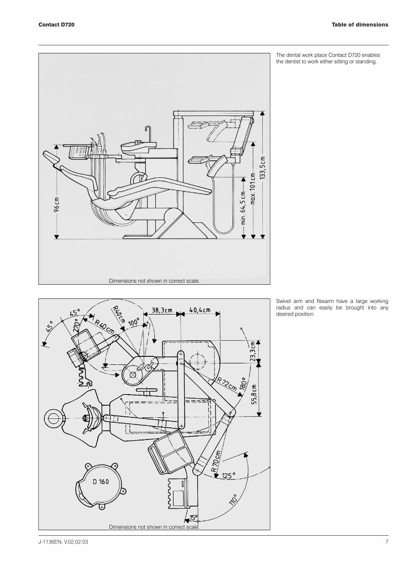
The dental work place Contact D720 enablesthe dentist to work either sitting or standing.
Swivel arm and flexarm have a large workingradius and can easily be brought into anydesired position.
Dimensions not shown in correct scale.
Dimensions not shown in correct scale.

Contact D720
8 J-1136EN, V.02.02.03
General instructions
The unit can be sold with or without HF electro-surgical unit. The specialobligations resulting from the classification have to be adherred to, i.e. theuser is obliged to perform technical. A the stock book (MPG § 22 andMPBetreibV §§ 5 ... 9.
The safety standards for medical products (MPG) and all legal obligationsare to be fully observed by the user.
Scope and schedules of safety-relevant inspections according to § 6 ofMPBetreibV 29.06.98 are as follows:
At least once a year the following safety-relevant inspections according toDIN VDE 0750 and DIN VDE 0751 have to be performed.
Visual inspection of equipment and accessories,inspection of groundconductor according to DIN VDE 0751,measurement of leakage currentaccording to DIN VDE 0751,performance test of the equipment giving dueregard to the accompanying documents.
We recommend to keep an equipment control log for documenting theresults of the safety-relevant inspections.
Please do not forget to return us the guarantee card within 15 days afterinstallation of the unit.
Our equipment complies to the safety standards for medical products(MPG) resp. the regulation 93/42/EEC for medical products.It alsocomplies to the VDE-requirements for electromedical devices DIN IEC601, part 1 / DIN VDE 0750, part 1.It is suited for connection to supplylines installed according to the VDE 0107 regulations for medically usedrooms.
We can only accept responsibility for the safety properties of our equip-ment, if installation, maintenance, repair and modifications are carried outby our workshop or by a person explixitly authorized by us. Further, theequipment has to be correctly handled according to our operatinginstructions.
In case of failure, structural parts effecting the security of the device are tobe replaced by original parts only.
In case of repair, the technician must issue a certificate as to the kind andextent of work performed and, if applicable, indicate any changes ofnominal data and operating range.The certificate must contain the date ofrepair, the name of the executing company and a signature (according toMPG, DIN VDE 0750 / DIN VDE 0751).
Close to the equipment do not operate any apparatus producing electro-magnetic emissions (such as wireless phones, micro-wave therapeuticsdevices,...).
According to law, electric equipment is to be disposed by authorizeddisposal firms only.
0366
In case of maintenance work or troubleshooting - Caution!Cut-off power supply first!
Ritter Concept GmbHBahnhofstraße 65, 08297 Zwönitz
Fon: 037754/13-0, Fax: 037754/13-342
e-mail: [email protected]: http://www.ritterconcept.de
Contact D720
J-1136EN, V.02.02.03 9
Notes
Contact D720Notes
10 J-1136EN, V.02.02.03

Ritter Contact D720
Dental unitOperating instructions
Ritter Concept GmbHBahnhofstraße 65, 08297 Zwönitz
Fon: 037754/13-0, Fax: 037754/13-342
e-mail: [email protected]: http://www.ritterconcept.de


Table of contentContact D720, Dentist's unit
J-1136EN, V.02.02.03 13
Table of content 13
Description 15
Order of instruments, instrumentation 16
Operation, burr change 17
Control elements 18
Control elements, foot panel 20
Control elements, 4-pedal foot controller 21
Programming the instruments 22
Instruments, Special functions of the foot panel 23
Air turbine 24
Micromotor 25
Ultrasonic scaler: ZEG 27
Topjet six-function syringe 29
Electro-surgical unit: Elektrotom 190 30
X-ray viewer 32
Dental operating light 33


Contact D720, Dentist's Unit
J-1136EN, V.02.02.03 15
Description
We recommend you to read this service manualvery carefully in order to have full knowledge ofall the advantages this dental work place is offe-ring you.
Contact D720, Dentist's Unit
Dentist's unit with free hanging instrumentHoses. Instrument section on flexarm. Supplyunit integrated in pedestal of supportingcolumn. Unit-mounting of dental operation lightStarlite D 428 as well as of X-ray viewer possible.Optionally, the dental work place can beequipped with the water disinfection systemWES D 628.
The main characteristics are:
� Compact configuration, little spacerequirement.
� Practice-adapted instrumentation with instru-ments on different levels
� Illumination for 3 burr instruments.� Motor control with firm tractive power in
every speed range. Setting for torque limita-tion.
� Reverse suction-free spray supply to all burrinstruments.
� Clear indicator fields showing the set func-tions.
� Programming of the functions and of the setvalues on different levels (Standard program,Alternative programs).
� Blocking of each chair function when anyinstrument is in operation.
� Integrated digital clock with STOP functionfor curing light.
� Single combined foot panel for dentist's unitand patient chair.
� Control elements for patient chair and assi-stant's unit.
� Instrument hoses with hose couplings. Waterdisinfection with very precise dosage. Safetyfor patient and equipment.
� Easy to move swivel arm (precision needle bearing) with pneumatic brakes.
� Small X-ray viewer integrated in controlpanel.
� Wear-resistant switch elements, pressuretransducer technique.
� Integrated double tray.� New design hinge connection, easy to clean.� Varnished surfaces, easy to clean.� Functional design, practice-oriented.� Optionally, the Contact D720 can be
equipped either with 4-pedal foot controlleror pilot foot switch.
Technical modifications reserved.

Contact D720,Dentist's unitOrder of instruments, instrumentation
16 J-1136EN, V.02.02.03
Order of instruments
The order of the instruments is ergonomical andadapted to the practice when working withhanging instrument hoses.
Instrumentation (example)
The instrumentation on the right shows a unitequipped with 5 instruments:
illuminated turbineilluminated micromotorilluminated micromotorPiezon scaler (optionally with light)Topjet six-function syringe
Operation, burr change Contact D720,Dentist's unit
J-1136EN, V.02.02.03 17
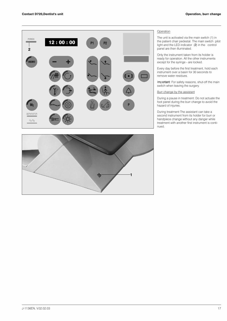
Operation
The unit is activated via the main switch (11) inthe patient chair pedestal. The main switch pilotlight and the LED indicator (22) in the controlpanel are then illuminated.
Only the instrument taken from its holder isready for operation. All the other instrumentsexcept for the syringe - are locked.
Every day before the first treatment, hold eachinstrument over a basin for 30 seconds toremove water residues.
IImmppoorrttaanntt:: For safety reasons, shut-off the mainswitch when leaving the surgery.
Burr change by the assistant
During a pause in treatment: Do not actuate thefoot panel during the burr change to avoid thehazard of injuries.
During treatment:The assistant can take asecond instrument from its holder for burr orhandpiece change without any danger whiletreatment with another first instrument is conti-nued.
1
12 : 00 : 002

Contact D720, Dentist's UnitControl elements
18 J-1136EN, V.02.02.03
20
1
22
23
12 : 00 : 00
15
16
14
12
17
7
21
8
9
13
11
2
19
10
6
4
5
3
18
UnitMain switch
1 Main switch at the patient chair or atconnection box ON/OFF
2 LED indicator illuminated:Unit ON via main switch
Starlite D428
33 key, dental operating light ON/OFF
X-ray viewer
44 X-ray viewer55 key, X-ray viewer ON/OFF66 film holder (magnet)
Patient chair
77 key, patient chair UP/DOWN88 ey, backrest UP/DOWN99 program key P1,1st treatment position1100 program key P2, 2nd treatment position1111 program key, mouth rinse position1122 program key, exit position
Cuspidor (assistant's unit)
1133 key, cup filler1144 key, bowl flush1155 LED indicator for amalgam separator
Water disinfection system
1166 LED indicator for water disinfectant (H2O2)
Bell, door opener
1177 key for door opener
Time setting
For time setting (1188)), all instruments must be intheir holders:� press key MEMO ((1199) (LED indicator must
light up)� press key MINUS (2200)) for setting the hours� press key PLUS ((2211) for setting the minutes� press key MEMO ((1199)) (LED indicator must
extinguish)
The seconds cannot be set.

Control elementsContact D720, Dentist's Unit
J-1136EN, V.02.02.03 9
20
M1 40000
21
18
31 28
29 30
33 32
26 27
24
19
25
Attention! The LED indicators of keys (24,26, 27, 28, 29, 30, 31, 32, 33) are only illu-minated when the instrument is takenfrom its holder.
The display (1188)) will indicate different information:
� time (when all instruments are parked)- theinstrument removed from the holder(T1 = turbine 1, M1 = micromotor 1, ZEG = scaler, SP = syringe, ECH = electro-surgical handpiece).
� The preselected speed or torque limitation ofthe micromotor, intensity of the electrosurgical unit or of the scaler, syringe heatingON. This information appears only then whenthe instrument is taken from its holder.
1199 program preparation key (MEMO)2200,,2211 key for setting speed, torque limitation and
intensity (also syringe heating).2244 Key, torque limitation of micromotor ON/OFF.2255 Program change-over key for instruments.
Instrument light:
2266 Key, instrument light ON/OFFLED indicator illuminated:instrument light ON.
2277 Key, intensity of instrument light MEDIUMLIGHT/MAXIMUM LIGHTLED indicator illuminated:instrument light at MAXIMUM LIGHT intensity.
Direction of motor rotation
2288 Key, direction of micromotor rotation.LED indicator illuminated: reverse operation ofmicromotor ON.
Spraywater for burr instruments
2299 Key, spraywater for burr instruments ON/OFF.LED indicator illuminated: spraywater for burrinstruments ON.
Chip blower
30 Key, chip blower constantly ON during drillingoperation. LED indicator illuminated: chipblower ON
Topjet syringe
3311 Key, syringe heating ON/OFF. LED indicatorilluminated: syringe heating ON
Ultrasonic scaler:
32 Key, endodontic function (root canaltreatment) ON/OFF. LED indicator illuminated:endodontic function ON

Contact D720, Dentist's unitControl elements, foot panel
20 J-1136EN, V.02.02.03
Foot panel -Functions of the different keys
All functions needed during treatmentcan be obtained and controlled via thekeys of the foot panel.
All keys have several functions - exceptfor the keys and .Which one ofthe functions is activated depends onwhether you are in the chair and instru-ment operation or in the Ritter IBW soft-ware operation. Further details areoutlined in the corrresponding sectionsof this operating instruction.
Symbols
n The indicated function is obtained by one short pressure of the key
nn The indicated function is obtained by twice shortly pressing the key
nnn The indicated function is obtained by longer pressure > 1 second of the key
Change of direction of micromotorrotation normal / reverse rotation
Instrument illumination
No function
Automatic movement to rinsing position
Automatic movement to exit position
Activation of the instrument function wheninstrument is out of holder Infinetelyvariable or preset speed or automaticmovement to exit position when allinstruments are in their holders
Keys are for chair positioning orwhen working with Ritter IBW software:Keys are for cursor control of RitterIBW software.
P1 Automatic movement to treatmentposition P1
Instrument spray
No function
P2 Automatic movement to treatmentposition P2
Chipblower ON (as long as key is beingpressed)
No function
Control elements, 4-pedal foot controllerContact D720, Dentist's unit
J-1136EN, V.02.02.03 21
1 2
3 4
5
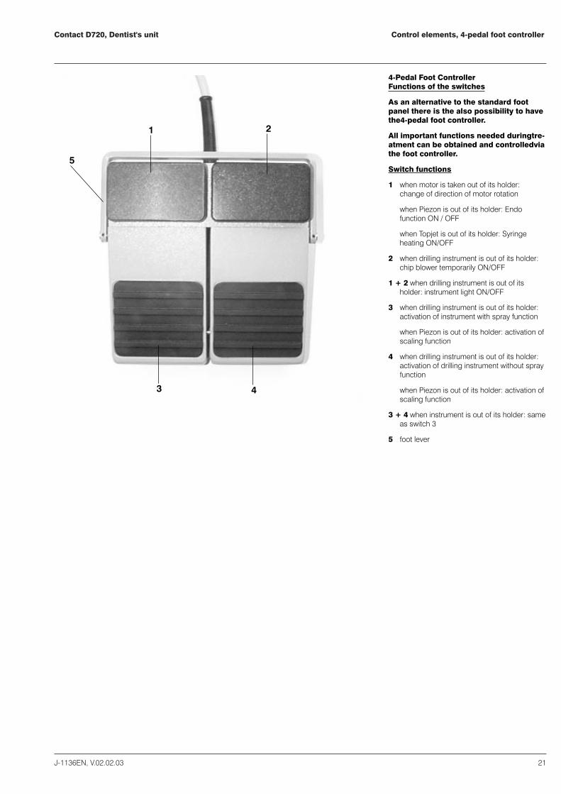
4-Pedal Foot ControllerFunctions of the switches
As an alternative to the standard footpanel there is the also possibility to havethe4-pedal foot controller.
All important functions needed duringtre-atment can be obtained and controlledviathe foot controller.
Switch functions
1 when motor is taken out of its holder:change of direction of motor rotation
when Piezon is out of its holder: Endofunction ON / OFF
when Topjet is out of its holder: Syringeheating ON/OFF
2 when drilling instrument is out of its holder:chip blower temporarily ON/OFF
1 + 2 when drilling instrument is out of itsholder: instrument light ON/OFF
3 when drilling instrument is out of its holder:activation of instrument with spray function
when Piezon is out of its holder: activation ofscaling function
4 when drilling instrument is out of its holder:activation of drilling instrument without sprayfunction
when Piezon is out of its holder: activation ofscaling function
3 + 4 when instrument is out of its holder: sameas switch 3
5 foot lever

Contact D720, Dentist's Unit
22 J-1136EN, V.02.02.03
Programming the instruments
20
M1 40000
21
18
28
29 30
26 27
24
19
25
Programming the instruments
All integrated functions can be programmed foreach instrument so that they are already presel-ected when the instrument is taken from itsholder.
Moreover, for each instrument two differentprograms can be stored (for two operators, forexample).
� SSttaannddaarrdd PPrrooggrraamm:: LCD indicator (18) does not blink.
� AAlltteerrnnaattiivvee PPrrooggrraamm::LCD indicator (18) blinks constantly in one-second intervals.
� Changing from one program to the other isperformed by pressing program change-over key (25) - whereby all instruments haveto be in their holders.
The functions are stored individually for eachin-strument, which for this purpose must bere-moved from its holder.
Example of program storage for micromotorAlternative Program
� All handpieces must be in their holders.
� Press program change-over key (25) tochange to the Alternative Program (LCDindicator (18) blinks constantly in one-second intervals).
� Take handpiece from its holder. Now, pressany of the desired key functions (keys 2244,,2266,, 2277,, 2288,, 2299 3300).
� Press the PLUS or MINUS key ((2200 or 2211) toset the speed. Indicated on LCD display(1188).
� Program storage is completed bypressingMEMO key (1199) and programchange-over key ((2255). Extinguishing of theLED indicator in the MEMO key confirms thatthe program has been stored.
For storing the Standard Program, pleaseproceed in the same way, however, withoutpressing MEMO key (1199)) and program change-over key ((2255))..
In case that one or the other of the preselectedfunctions of an instrument should be changedor deleted, change over to the alternativeprogram by pressing program change-over key(25), take the handpiece from its holder and addor delete the desired function by briefly pres-singthe appropriate function key. Thesechanges, however, are maintained only untilthenext change-over to the Standard Programismade. All programmed functions are stillpresent and unchanged after the handpiece hasbeen returned into its holder again.
The instrument Standard Program haspriority,that means, after activating the dental-work place via the main switch the StandardProgram will automatically be operative.
Contact D720, Dentist's unit
J-1136EN, V.02.02.03 23
Instruments, Special functions of the footpanel
134135136107107
108
108
137
112
111
134135136107107
108
108
137
112
111
138 139
140 141
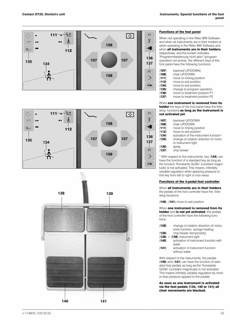
Functions of the foot panel
When not operating in the Ritter IBW Softwareand when all instruments are in their holders orwhen operating in the Ritter IBW Software andwhen all instruments are in their holders,respectively, and the screen indicates"Programmbedienung nicht aktiv" (programoperation not active), the different keys of thefoot panel have the following functions:
(107) backrest UP/DOWN((108) chair UP/DOWN (111) move to rinsing position(112) move to exit position(134) move to exit position(135) change to program operation(136) move to treatment position P1(137) move to treatment position P2
When one instrument is removed from itsholder the keys of the foot panel have the follo-wing functions as long as the instrument isnot activated yet:
(107) backrest UP/DOWN(108) chair UP/DOWN(111) move to rinsing position(112) move to exit position(134) activation of the instrument function1)
(135) change of rotation direction of motor or instrument light
(136) spray(137) chip blower
1) With respect to the instruments, key (134) canhave the function of a standard key as long asthe function "Konstante Größe" (constant magni-tude) is not activated. This means, infenitelyvariable regulation when applying pressure tothis key from left to right or vice versa.
Functions of the 4-pedal-foot controller
When all instruments are in their holders,the pedals of the foot controller have the follo-wing functions:
(140), (141) move to exit position
When one instrument is removed from itsholder and is not yet activated, the pedalsof the foot controller have the following func-tions:
(138) change of rotation direction of motor, endo function, syringe heating
(139) chip blower (temporarily)(138) + (139) instrument light(140) activation of instrument function with
water(141) activation of instrument function
without water
With respect to the instruments, the pedals(140) and (141) can have the function of stan-dard foot pedals as long as the "KonstanteGröße" (constant magnitude) is not activated.This means infinitely variable regulation by moreor less pressure applied to the pedals.
As soon as one instrument is activatedvia the foot pedals (134, 140 or 141) allchair movements are blocked.

Contact D720, dentist's unit
24 J-1136EN, V.02.02.03
Air turbine
3435
38 39
40 41
3736
T1 100 %
18
29 30
26 27
Operation
Take the handpiece from its holder.
The turbine is activated via the foot panel (34) orthe foot controller pedals (40, 41).
The turbine speed appears in the LCD display(18) as 100 % value and cannot be changed.
Turbine light
The turbine light is switched ON (and OFF, resp.)by key (26) (LED indicator illuminated). Theturbine light extinguishes 5 seconds after takingthe foot from the foot panel / foot controller orimmediately after returning the handpiece into theholder and illuminates again when taking thehandpiece from its holder and applying pressureto the foot panel (34) or foot controller pedals (40,41).
The light intensity can be increased by pressingkey (27) and is confirmed by illumination of theLED indicator.
There are two degrees of light intensity:MEDIUM intensity (26)MAXIMUM intensity (26 + 27)
Spraywater
The turbine spraywater is switched on by key (29)LED indicator illuminates.
Chip blower
For an increased air stream and better chipremoval during the drilling operation, the chipblower can be switched for continuous operationby pressing key (30) in the control panel.
Programmable functions
Functions of the turbine: turbine light, spraywaterand continuous chip blower operation areprogrammable.
Foot panel
34 operation of turbine35 pressing key twice within half a second,
turbine light ON/OFF36 key, spray ON/OFF37 key, chip blower air only
4-Pedal-foot controller
4400 operation of turbine with spray4411 operation of turbine without spray4400 ++ 4411 operation of turbine with spray3388 ++ 3399 turbine light ON/OFF3399 chip blower
Delayed function of the chip blower whenactivated via the foot panel.
Immppoorrttaanntt:: Please read the turbine manufacturer'sinstructions very carefully.
Contact D720, Dentist's Unit
J-1136EN, V.02.02.03 25
Micromotor
3435 3736
20
M1 40000
21
18
28
29 30
26 27
24
19
38 39
40 41
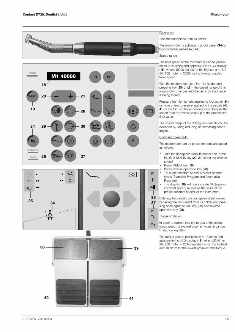
IOperation
Take the handpiece from its holder.
The micromotor is activated via foot panel ((34) orfoot controller pedals (4400,, 4411).
Speed range
The final speed of the micromotor can be presel-ected in 24 steps and appears in the LCD display(1188), where 40000 stands for the highest and 400(KL 700 motor = 2000) for the lowest preselec-table speed.
With the micromotor taken from its holder andpressing key (2200) or (2211), the speed range of thismicromotor changes and the last indicated valueis being stored.
Pressure from left to right applied to foot panel (3344)or more or less pressure applied to the pedals (4400,4411) of the foot controller continuously changes thespeed from the lowest value up to the preselectedfinal value.
The speed range of the drilling instruments can beextended by using reducing or increasing contra-angles.
Constant Speed (MF)
The micromotor can be preset for constant speedas follows:
� Take the handpiece from its holder and pressPLUS or MINUS key (2200, 2211) to set the desiredspeed.
� Press MEMO key (1199)� Press reverse operation key (2288)� Thus, the constant speed is preset on both
levels (Standard Program and AlternativeProgram)
� The display (1188) will now indicate MF (sign forconstant speed) as well as the value of thepreset constant speed for the instrument.
Deleting the preset constant speed is performedby taking the instrument from its holder and pres-sing once again MEMO key (1199) and reverseoperation key (2288).
Torque limitation
In order to warrant that the torque of the micro-motor does not exceed a certain value, it can belimited via key (2244).
The torque can be preselected in 13 steps andappears in the LCD display (1188), where 22 Nmm(KL 700 motor = 25 Nmm) stands for the highestand 10 Nmm for the lowest preselectable torque.

Contact D720, Dentist's Unit
26 J-1136EN, V.02.02.03
Micromotor
When the micromotor is taken from its holderand pressing key (2244), the value of the torquecan be preselected with keys (2200 or 2211) and thelast indicated value is being stored.
Micromotor light (2266, 2277)
Please refer to turbine light.
Reverse operation of the micromotor
Reverse operation of the micromotor is effectedby key (2288). LED indicator illuminates.
Spraywater
Spraywater for the micromotor is switched onvia key (2299). LED indicator illuminates.
Chip blower with continuous operation
For an increased air stream and better chipremoval during the drilling operation, the chipblower can be switched for continuous opera-tion by pressing key (3300) in the control panel.
Programmable functions
Functions of the micromotor: speed range,torque limitation, micromotor light, reverseoperation, spraywater and continuous chipblower operation are programmable.
Foot panel
3344 operation of micromotor and speedregulation
3355 pressing key once:reverse operation of micromotor ON/OFFpressing key twice (within half a second):instrument light ON/OFF
3366 key, spray ON/OFF3377 key, chip blower, air only
4-Pedal-foot controller
4400 operation of micromotor with spray4411 operation of micromotor without spray4400 + 4411 operation of micromotor with spray3388 + 3399 instrument light ON/OFF3388 reverse operation of micromotor ON/OFF3399 Chip blower
Immppoorrttaanntt:: Please read the micromotor manu-facturer's instructions very carefully.

Contact D720, Dentist's unit
J-1136EN, V.02.02.03 27
Ultrasonic scaler: ZEG
43
34
20
ZEG 100 %
21
18
28
32
19
38
40 41
26 27
35
39
Technical data:
mode of operation: DAB*
optionally with light
BF
MMoorree tteecchhnniiccaall ddaattaa aanndd ooppeerraattiinngg hhiinnttss ccaann bbeeffoouunndd iinn tthhee ooppeerraattiinngg iinnssttrruuccttiioonnss ffoorr tthhee hhaanndd--ppiieeccee wwhhiicchh aarree eenncclloosseedd!!
Operation
Take the handpiece from its holder.
The scaler is activated via foot panel, key (3344) orfoot controller pedals (4400, 4411).
*DAB = continuous operation with intermittentload. The permissible load times are adapted tothe working mode of the dentist.
Intensity
The intensity of the scaler can be preselected in5-percent-steps and appears in the LCD display(1188), whereby 100 % stands for the highest and20 % for the lowest preselectable intensity.
With the handpiece taken from its holder andpressing key (2200 or 2211), the intensity can bechanged.
Pressure from left to right applied to key (3344) ofthe foot panel or more or less pressure appliedto the foot pedals (4400, 4411) continuously changesthe speed from the lowest value up to thepreselected final value.
Constant Intensity (ZF)
The ultrasonic scaler can be preset for constantintensity:
� Take the handpiece from its holder andpress PLUS or MINUS key (2200, 2211) to set thedesired intensity.
� Press MEMO key (1199)� Press reverse operation key (2288)� Thus, the constant intensity is preset on both
levels (Standard Program and AlternativeProgram)
� The display (1188) will now indicate ZF (sign forconstant intensity) as well as the value of thechosen preset constant intensity.
Deleting the preset constant intensity isperformed by taking the instrument from itsholder and pressing once again MEMO key (19)and reverse operation key (2288).
Endo Function
The endodontic function (root canal treatment)is activated by key (3322). LED indicator illumi-nates.
Water regulation
For water regulation, the scaler Piezon PZ isprovided with a knurled nut (3333) on the hand-piece.

Contact D720, Dentist's Unit
28 J-1136EN, V.02.02.03
Ultrasonic scaler: ZEG
Handpiece light (26, 27)
visit to turbine light
Programmable functions
Functions of the scaler: intensity and Endofunction are programmable.
Foot panel
34 Operation of the scaler and intensityregulation.
35 pressing key twice within half a second,handpiece light ON/OFF
4-Pedal foot controller
40 or/and 41 operation of the scaler38 Endo function ON/OFF3388 ++ 3399 handpiece light ON/OFF
Important: Please read the manufacturer'sinstructions for the ultrasonic scaler verycarefully.
Contact D720, Dentist's unit
J-1136EN, V.02.02.03 29
Topjet six-function syringe
44 47
45
46
20
SP kalt
21
18
31
38
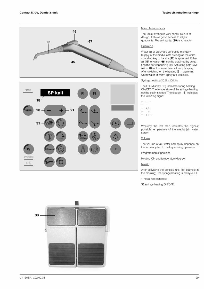
Main characteristics
The Topjet syringe is very handy. Due to itsdesign, it allows good access to all jawquadrants. The syringe tip (39) is rotatable.
Operation
Water, air or spray are controlled manuallySupply of the media lasts as long as the corre-sponding key of handle (4477) is epressed. Eitherair (4455) or water (46) can be obtained by actua-ting the corresponding key. Actuating both keys(4455 + 4466) at the same time will supply spray.After switching on the heating (3311), warm air,warm water or warm spray are available.
Syringe heating (20 % - 100 %)
The LCD display (1188) indicates syring heatingON/OFF. The temperature of the syringe heatingcan be set in 5 steps. The display (1188) indicatesthe following signs:
� - - -� - -� +/-� ++� +++
Whereby the last step indicates the highestpossible temperature of the media (air, water,spray).
Volume
The volume of air, water and spray depends onthe force applied to the keys during operation.
Programmable functions
Heating ON and temperature degree.
Notes:
After activating the dentist's unit (for example inthe morning), the syringe heating is always OFF.
4-Pedal foot controller
3388 syringe heating ON/OFF.

Contact D720, Dentist's unit
30 J-1136EN, V.02.02.03
Electro-surgical unit: Elektrotom 190
Technical Data
supply voltage: 33V DC
rated input: 75 VA
rated frequency: 500 kHz ± 10 %
max. HF-rated capacity: 50 W / 400 W
mode of operation: DAB(ED=25 %)*
Operation
Take the handpiece from its holder. The electro-surgical handpiece is activated via the key (3344)of the foot panel or pedal (4400,, 4411) of the footcontroller.
*DAB = continuous operation with intermittentload. In case of an operation of 25 % this corre-sponds for instance 6 sec. OPERATING TIME -15 sec. PAUSE.
Intensity
The intensity of the electro-surgical unit can bepreselected in 5-percent-steps and appears inthe LCD display (1188), whereby 100 % stands forthe highest and 20 % for the lowest preselec-table intensity.
With the handpiece taken from its holder andpressing key (2200 or 2211), the intensity can bechanged. Pressure from left to right applied tokey (3344) of the foot panel or more or less pres-sure to pedals (4400, 4411) of the 4-pedal footcontroller continuously changes the speed fromthe lowest value up to the preselected finalvalue.
Constant Intensity
The electro-surgical unit can be preset forconstant intensity:
� Take the handpiece from its holder and press PLUS or MINUS key (2200, 2211) to set the desired intensity.
� Press MEMO key (1199)� Press reverse operation key (2288)� Thus, the constant intensity is preset on both
levels (Standard Program and AlternativeProgram).
� The display (1188) now indicates EF sign forcontant intensity) as well as the value of thechosen preset contant intensity.
Deleting the preset constant intensity isperformed by taking the instrument from itsholder and pressing once again MEMO key (1199)and reverse operation key (2288).
Automatic operation
For automatic operation of the electro-surgicalunit press key (3333). LED indicator illuminated.
34
20
ECH 100 %
21
18
28
33
19
40 41
Contact D720, Dentist's unit
J-1136EN, V.02.02.03 31
Electro-surgical unit: Elektrotom 190
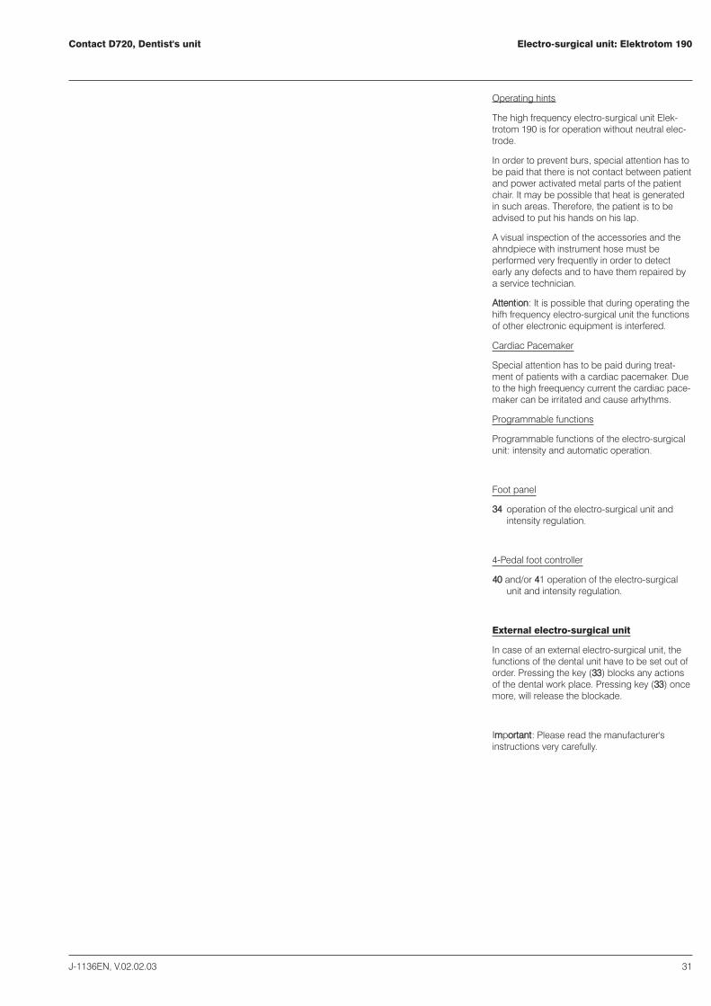
Operating hints
The high frequency electro-surgical unit Elek-trotom 190 is for operation without neutral elec-trode.
In order to prevent burs, special attention has tobe paid that there is not contact between patientand power activated metal parts of the patientchair. It may be possible that heat is generatedin such areas. Therefore, the patient is to beadvised to put his hands on his lap.
A visual inspection of the accessories and theahndpiece with instrument hose must beperformed very frequently in order to detectearly any defects and to have them repaired bya service technician.
AAtttteennttiioonn: It is possible that during operating thehifh frequency electro-surgical unit the functionsof other electronic equipment is interfered.
Cardiac Pacemaker
Special attention has to be paid during treat-ment of patients with a cardiac pacemaker. Dueto the high freequency current the cardiac pace-maker can be irritated and cause arhythms.
Programmable functions
Programmable functions of the electro-surgicalunit: intensity and automatic operation.
Foot panel
3344 operation of the electro-surgical unit andintensity regulation.
4-Pedal foot controller
4400 and/or 4411 operation of the electro-surgicalunit and intensity regulation.
External electro-surgical unit
In case of an external electro-surgical unit, thefunctions of the dental unit have to be set out oforder. Pressing the key (3333) blocks any actionsof the dental work place. Pressing key (3333) oncemore, will release the blockade.
IImmppoorrttaanntt: Please read the manufacturer'sinstructions very carefully.

Contact D720, Dentist's unitX-ray viewer
32 J-1136EN, V.02.02.03
Optionally, the dentist's unit can be equippedwith X-ray viewer D558 (5500).
The X-ray viewer has an illuminated panoramicscreen of 29 cm x 12.5 cm and is mounted tothe carrier arm of the tray table (5511).
Main Characteristics
� horizontally movable by 90 º.� uniform illumination of the screen with a
powerful light of 12,000 Lux� the screen is inclined by 15 o which allows
optimum posture and best vision for theoperator.
� easy to clean due to its rounded shape.
Control elements
5522 screen5533 film holder5544 switch
Operation
Switch (5544) ON/OFF when the dental work placeis switched ON.
50
52
53
54
51
Dental operating lightContact D720,Dentist's unit
J-1136EN, V.02.02.03 33
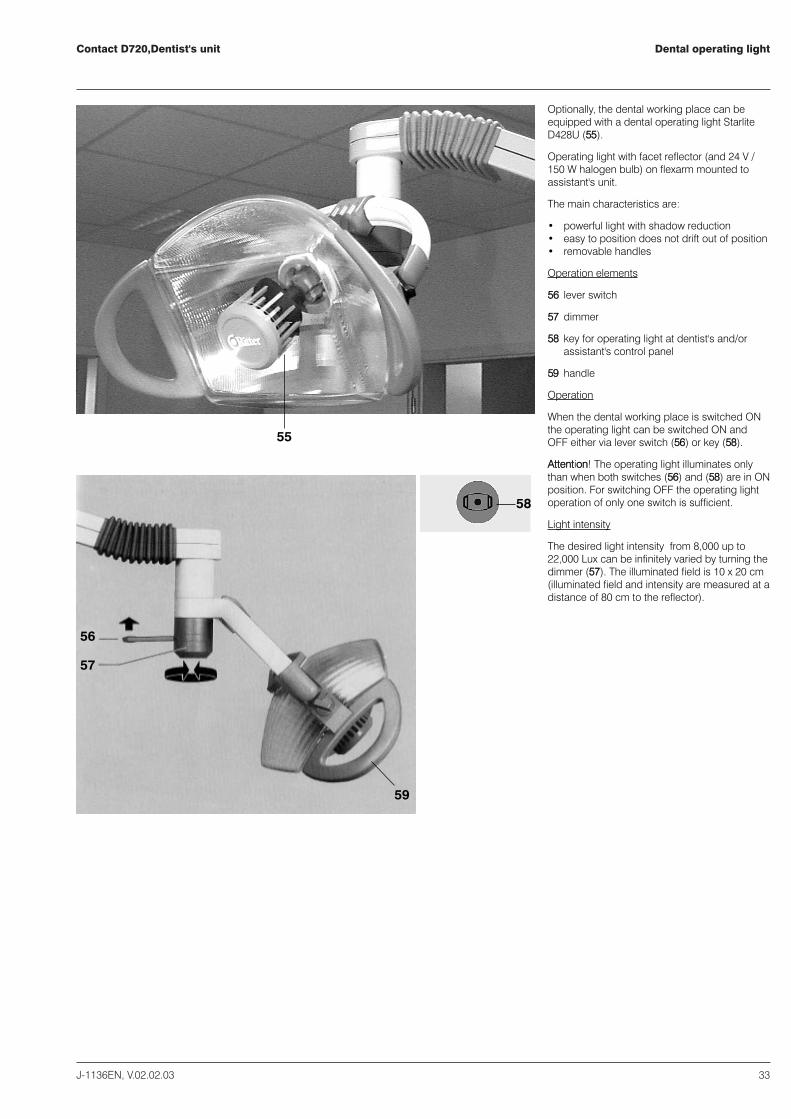
55
56
57
59
58
Optionally, the dental working place can beequipped with a dental operating light StarliteD428U (5555).
Operating light with facet reflector (and 24 V /150 W halogen bulb) on flexarm mounted toassistant's unit.
The main characteristics are:
� powerful light with shadow reduction� easy to position does not drift out of position� removable handles
Operation elements
5566 lever switch
5577 dimmer
5588 key for operating light at dentist's and/orassistant's control panel
5599 handle
Operation
When the dental working place is switched ONthe operating light can be switched ON andOFF either via lever switch (5566) or key (5588).
AAtttteennttiioonn!! The operating light illuminates onlythan when both switches (5566) and (5588) are in ONposition. For switching OFF the operating lightoperation of only one switch is sufficient.
Light intensity
The desired light intensity from 8,000 up to22,000 Lux can be infinitely varied by turning thedimmer (5577). The illuminated field is 10 x 20 cm(illuminated field and intensity are measured at adistance of 80 cm to the reflector).
Contact D720, Dentist's unit
34 J-1136EN, V.02.02.03
Notes
Ritter Contact D720Dental patient chair- Operating instructions
Ritter Concept GmbHBahnhofstraße 65, 08297 Zwönitz
Fon: 037754/13-0, Fax: 037754/13-342
e-mail: [email protected]: http://www.ritterconcept.de


ContentsContact D720, Patient Chair
J-1136EN, V.02.02.03 37
Contents 37
Description 39
Working Area 40
Operation 41
Control elements, manual control 42
Program control, programming the chair positions 43
Safety stops 44
Head supports, handgrip 45


DescriptionContact D720, Patient Chair
J-1136EN, V.02.02.03 39
Technical modifications reserved.
We recommend you to read this service manualvery carefully in order to have full knowledge ofall the advantages this chair is offering you.
Contact D720, Patient Chair
Free programmable motor chair for dentists andorthodontists.
The main characteristics are:
� quickset programming for four chairpositions
� maintenance-free spindle motors, veryreliable and extremely quiet
� great height adjustment for working in sittingor standing position
� large adjustment range of backrest forreclined and upright backrest position
� backrest with integrated arm support� slim backrest for more leg room� comfortable seat portion, soft and anatomi-
cally shaped� small, round head support, enables the
dentist to get even closer to the patient(standard type).As an option: Longish head support andchildren's head wedge.
� large adjustment angle of head support foreasier treatment of upper and lower jaw
� recessed backrest portion for head supportto allow better support of small patients
� handgrip for patient� operation of patient chair either manually via
dentist's unit and assistant's unit or via thefoot panel or the optional pilot foot switch
� safety stops, in order to avoid the hazards ofinjury, especially during programmed opera-tions

Contact D720, Patient ChairWorking Area
40 J-1136EN, V.02.02.03
The patient chair allows the dentist to workeither sitting or standing.
Differentiated movement between backrestinclination and seat inclination, mechanicallycoupled.
SS highest backrest position
MM medium backrest position
TT lowest backrest position
Dimensions of patient chair
OperationContact D720, Patient Chair
J-1136EN, V.02.02.03 41
1
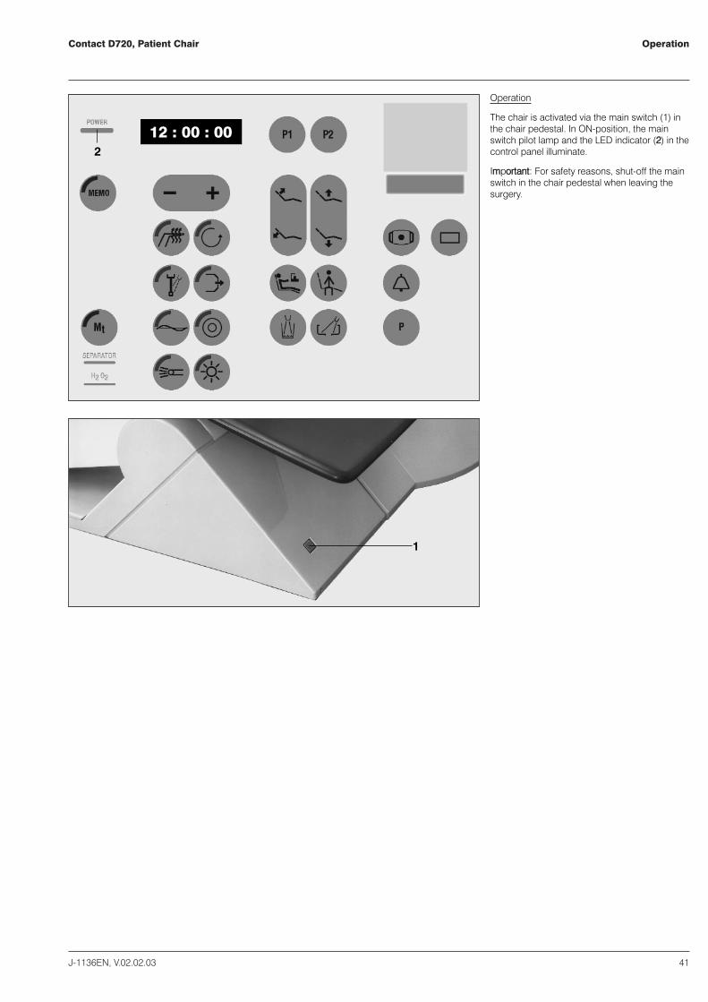
Operation
The chair is activated via the main switch (11) inthe chair pedestal. In ON-position, the mainswitch pilot lamp and the LED indicator (22) in thecontrol panel illuminate.
IImmppoorrttaanntt:: For safety reasons, shut-off the mainswitch in the chair pedestal when leaving thesurgery.
12 : 00 : 002
Contact D720, Patient ChairControl elements, manual control
42 J-1136EN, V.02.02.03
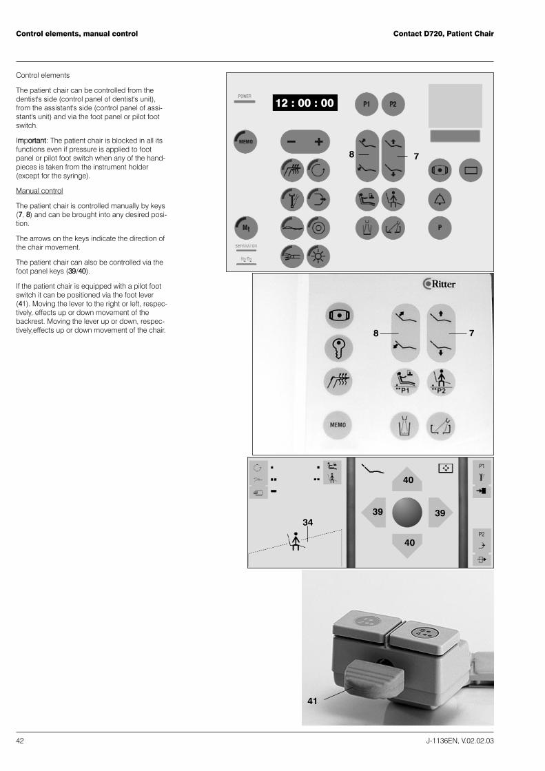
Control elements
The patient chair can be controlled from thedentist's side (control panel of dentist's unit),from the assistant's side (control panel of assi-stant's unit) and via the foot panel or pilot footswitch.
IImmppoorrttaanntt:: The patient chair is blocked in all itsfunctions even if pressure is applied to footpanel or pilot foot switch when any of the hand-pieces is taken from the instrument holder(except for the syringe).
Manual control
The patient chair is controlled manually by keys(77, 88) and can be brought into any desired posi-tion.
The arrows on the keys indicate the direction ofthe chair movement.
The patient chair can also be controlled via thefoot panel keys (3399/4400).
If the patient chair is equipped with a pilot footswitch it can be positioned via the foot lever(4411). Moving the lever to the right or left, respec-tively, effects up or down movement of thebackrest. Moving the lever up or down, respec-tively,effects up or down movement of the chair.
3939
40
40
34
41
78
12 : 00 : 00
78
Program control, programming the chairpositions
Contact D720, Patient Chair
J-1136EN, V.02.02.03 43
343736
1413
15
12
9
11
10
19
38
12 : 00 : 00
42
43
44 44
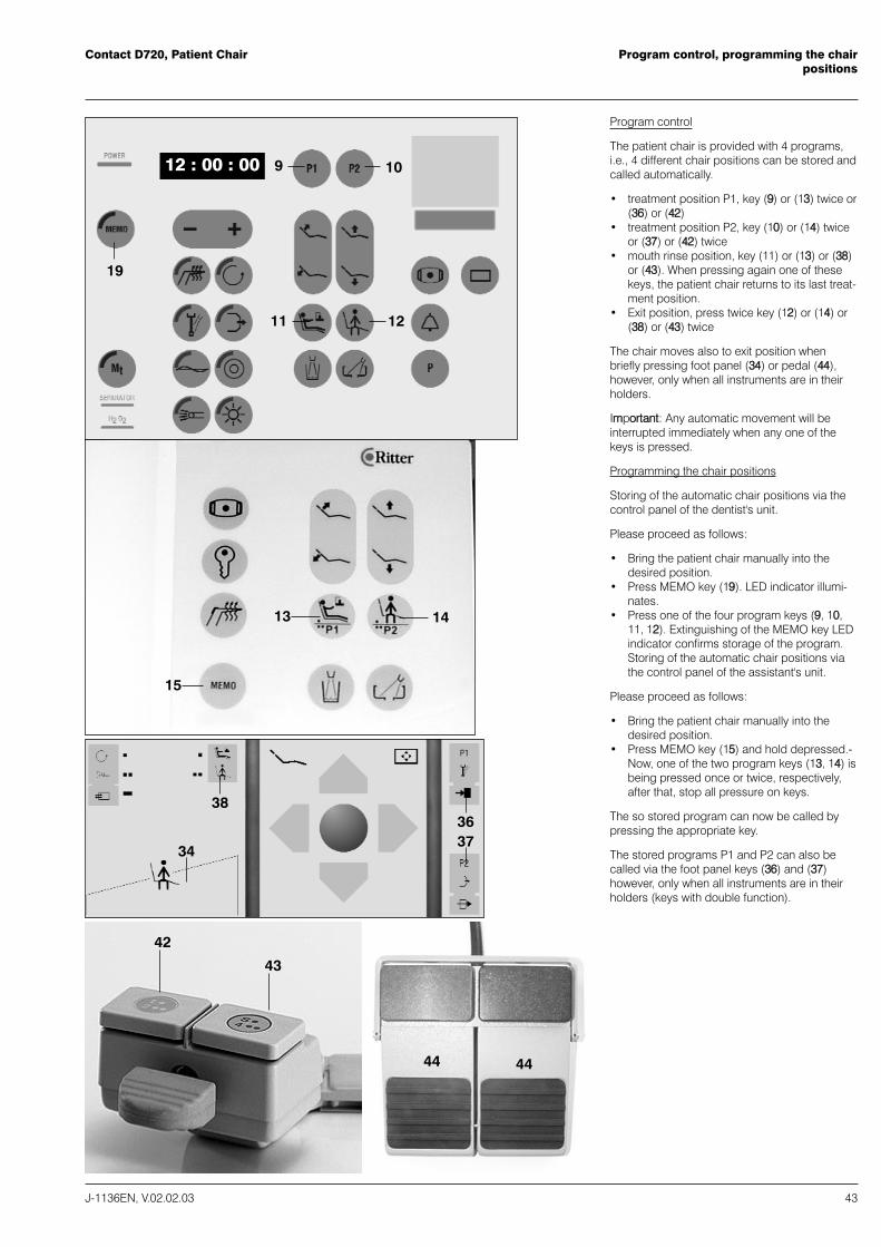
Program control
The patient chair is provided with 4 programs,i.e., 4 different chair positions can be stored andcalled automatically.
� treatment position P1, key (99) or (1133) twice or(3366) or (4422)
� treatment position P2, key (1100) or (1144) twiceor (3377) or (4422) twice
� mouth rinse position, key (1111) or (1133) or (3388)or (4433). When pressing again one of thesekeys, the patient chair returns to its last treat-ment position.
� Exit position, press twice key (1122) or (1144) or(3388) or (4433) twice
The chair moves also to exit position whenbriefly pressing foot panel (3344) or pedal (4444),however, only when all instruments are in theirholders.
IImmppoorrttaanntt:: Any automatic movement will beinterrupted immediately when any one of thekeys is pressed.
Programming the chair positions
Storing of the automatic chair positions via thecontrol panel of the dentist's unit.
Please proceed as follows:
� Bring the patient chair manually into thedesired position.
� Press MEMO key (1199). LED indicator illumi-nates.
� Press one of the four program keys (99,, 1100,,1111,, 1122). Extinguishing of the MEMO key LEDindicator confirms storage of the program.Storing of the automatic chair positions viathe control panel of the assistant's unit.
Please proceed as follows:
� Bring the patient chair manually into thedesired position.
� Press MEMO key (1155) and hold depressed.-Now, one of the two program keys (1133,, 1144) isbeing pressed once or twice, respectively,after that, stop all pressure on keys.
The so stored program can now be called bypressing the appropriate key.
The stored programs P1 and P2 can also becalled via the foot panel keys (3366) and (3377)however, only when all instruments are in theirholders (keys with double function).
Contact D720, Patient chairSafety stops
44 J-1136EN, V.02.02.03
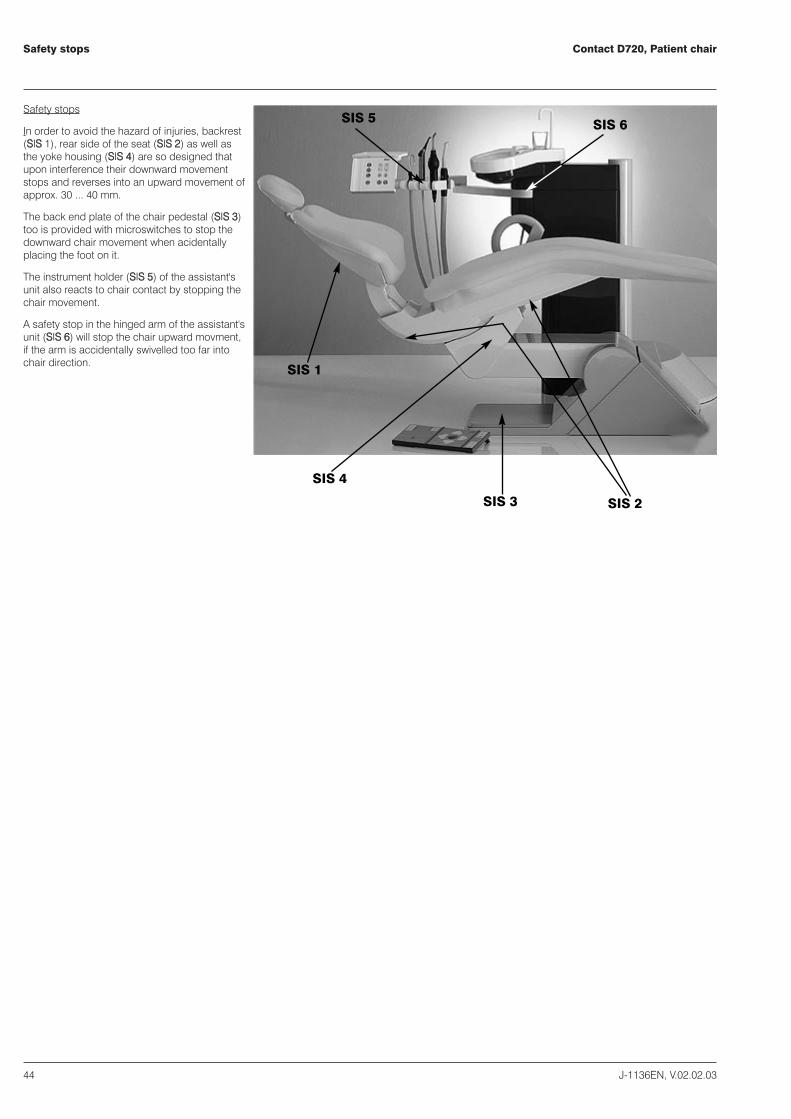
Safety stops
In order to avoid the hazard of injuries, backrest(SSIISS 11), rear side of the seat (SSIISS 22) as well asthe yoke housing (SSIISS 44) are so designed thatupon interference their downward movementstops and reverses into an upward movement ofapprox. 30 ... 40 mm.
The back end plate of the chair pedestal (SSIISS 33)too is provided with microswitches to stop thedownward chair movement when acidentallyplacing the foot on it.
The instrument holder (SSIISS 55) of the assistant'sunit also reacts to chair contact by stopping thechair movement.
A safety stop in the hinged arm of the assistant'sunit (SSIISS 66) will stop the chair upward movment,if the arm is accidentally swivelled too far intochair direction.
SIS 1
SIS 4
SIS 3 SIS 2
SIS 5 SIS 6

Head supports, handgripContact D720, Patient Chair
J-1136EN, V.02.02.03 45
Head support
Extension and tilting of the head support can
be easily performed with one hand only. Theheight adjustment of the head support is infini-tely variable (self-locking). The extension lengthis approx. 15 cm.
For tilting backwards, locking device (5500) has tobe released by pulling.Tilting forwards can beperformed without pulling the locking device.The head support can be taken off and insertedagain without problems.
Handgrip
The handgrip (5511) supports the patient whenmouth rinsing.
Illustration on the left:Longish head support
Illustration on the right:Standard head support and children's headwedge
50
51

Contact D720, Patient chairNotes
46 J-1136EN, V.02.02.03

Ritter Contact D720
Assistant's UnitOperating instructions
Ritter Concept GmbHBahnhofstraße 65, 08297 Zwönitz
Fon: 037754/13-0, Fax: 037754/13-342
e-mail: [email protected]: http://www.ritterconcept.de

ContentsContact D720, Assistant's unit
J-1136EN, V.02.02.03 49
Contents 49
Description 51
Working area 52
Control elements 53
Cup filling 54
Bowl flush 55
Saliva ejector, surgical suction 56
Suction handpiece 57
Topjet six-function syringe 58
Curing light: Lysta 59
Hydrocolloid quick connection 60
Hygiene System H1 61
Amalgam Separator MST 1 62
Water Disinfection System WES D628 63
Valve for bowl rinse 64

Contact D720, Assistant's unit
J-1136EN, V.02.02.03 51
Description
Technical modifications reserved.
We recommend you to read this service Manualvery carefully in order to have full knowledge ofall the advantages this assistant's unit is offeringyou.
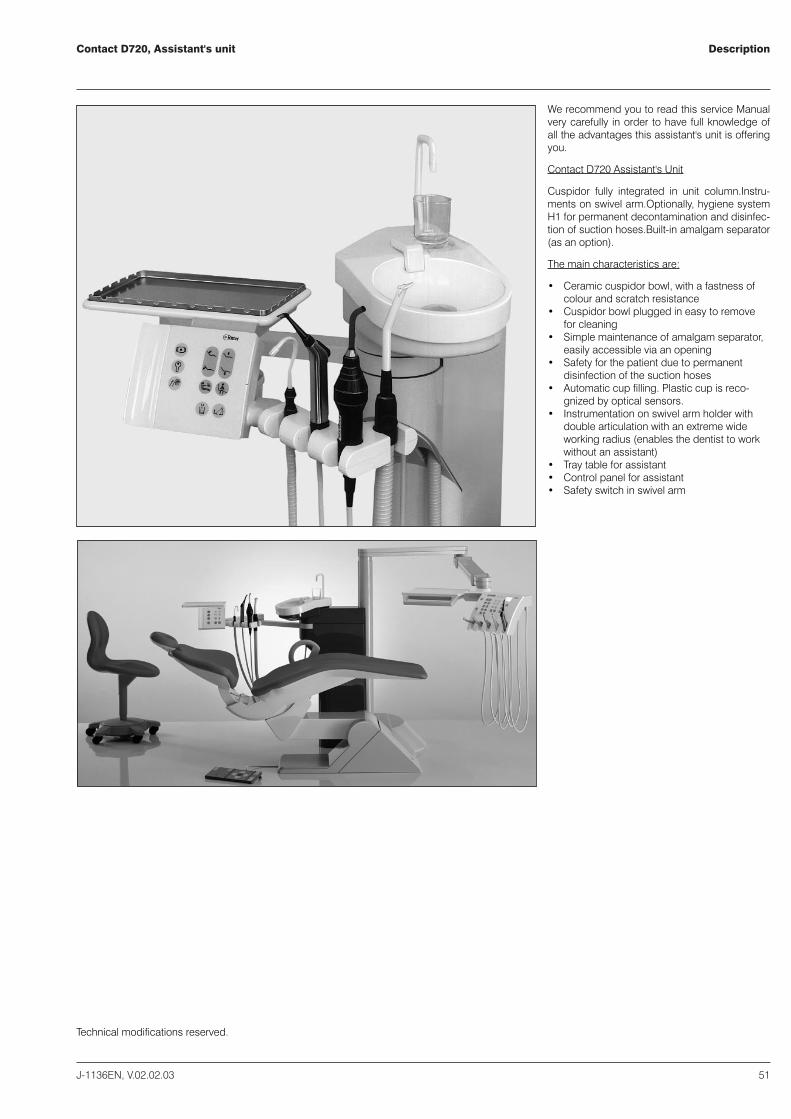
Contact D720 Assistant's Unit
Cuspidor fully integrated in unit column.Instru-ments on swivel arm.Optionally, hygiene systemH1 for permanent decontamination and disinfec-tion of suction hoses.Built-in amalgam separator(as an option).
The main characteristics are:
� Ceramic cuspidor bowl, with a fastness ofcolour and scratch resistance
� Cuspidor bowl plugged in easy to removefor cleaning
� Simple maintenance of amalgam separator,easily accessible via an opening
� Safety for the patient due to permanentdisinfection of the suction hoses
� Automatic cup filling. Plastic cup is reco-gnized by optical sensors.
� Instrumentation on swivel arm holder withdouble articulation with an extreme wideworking radius (enables the dentist to workwithout an assistant)
� Tray table for assistant� Control panel for assistant� Safety switch in swivel arm

Contact D720, Assistant�s unitWorking area
52 J-1136EN, V.02.02.03
The assistant's unit is integrated in the unitcolumn. No cables or supply hoses on thefloor.
The double-arm of the assistant's unit has anextremely wide working radius. Instrumentholder and control panel with tray table can bebrought very close to the patient or swivelledfar off in order to give the assistant space.
Dimensions are not shown in correct scale.
Dimensions are not shown in correct scale.

Control elementsContact D720, Assistant's unit
J-1136EN, V.02.02.03 53
1
57
63
3
65
66
67
56
58
606259
61
8
11
13
7
12
91
1516
68
212 : 00 : 00
52 53 54 55
56
11 main switch ON/OFF2 LED indicator illuminated: work place ON via
main switch 3 key, dental operating light ON/OFF77 key, patient chair UP/DOWN88 key, backrest UP/DOWN1111 program key, mouth rinsing position, treat-
ment position 1112 program key, exit position, treatment position
2113 key, cup filler114 key, bowl flush115 amalgam separator, LED indicator blinks
slowly (2-second intervals): amalgamcollector is 95 % full LED indicator blinksquickly (1-second intervals): centrifugedisturbance
1166 water disinfection system LED indicatorblinks: water disinfectant H2O2 must berefilled LED indicator constantly illuminated:disturbance of water disinfection system
52 cuspidor bowl53 pipe for bowl flush. The pipe can be taken
off for cleaning the bowl. Before doing so, itis absolutely necessary to switch off the unitvia the main switch (11) in the patient chairpedestal!
54 cup, not transparent55 cup filler. Can be taken off for cleaning the
bowl. Before doing so, it is absolutely neces-sary to switch off the unit via the main switch(11) in the patient chair pedestal!
566 swivel arm with double articulation577 tray table588 instrument holder599 saliva ejector6600 spray suction6611 syringe662 curing light663 control panel, assistant's unit665 door opener6666 key, syringe heating ON/OFF6677 Memo key6688 hydrocolloid quick-connection optionally,
the assistant's unit can be provided with ahydrocolloid quick- connection
Keys (1111) and (112) have double functions:Pres-sing them quickly twice corresponds to
1111 treatment position P1112 treatment position P2
AAtttteennttiioonn!!
Switch off the unit at the main switch in thepatient chair pedestal before removing cup fillerand pipe for bowl flush.

Contact D720, Assistant's UnitCup filling
54 J-1136EN, V.02.02.03
13 14
69
68
70
5553
19
19
12 : 00 : 00
13 14
Cup filling
To fill the cup, there is a choice of two programs- either MANUAL AUTOMATIC or SEMI-AUTO-MATIC. Factory setting is manual automatic. Asubsequent change can be made by the servicetechnician.
The filling level is dependent on the previousmanual cup filling procedure. Place glass orplastic cup on the support plate. Press MEMOkey (1199) of dentist's control panel (LED indicatorilluminated). Now, press key (113) until the glassor plastic cup has reached the desired fillinglevel. Extinguishing of the MEMO key LED indi-cator and three beeps confirm that program-ming of the filling level has been stored.Alternatively, cup filling level can also be storedby simultaneously pressing keys (1199) and (113) ofthe assistant's unit until the desired filling levelis reached. Recommended filling level: twothirds of the glass or plastic cup.
Accidential excess water will vanish via the cupsupport plate.
MANUAL AUTOMATIC
By pressing key (113) the glass or plastic cup isbeing filled. The filling procedure stops automa-tically. Premature stop of filling procedure: presskey (113) once more.
SEMI-AUTOMATIC
The glass or plastic cup is automatically filledafter placing it onto the support plate (with atime lag of 3 seconds).
By pressing key (113) the filling level can beincreased.
Factory setting is manual automatic.
A subsequent change can be made by theservice technician.
IImmppoorrttaanntt:: Do not use any transparent glasses.The water intensity of the cup filler (55) is regu-lated with adjustment knob (6699). Turning the nobto the left increases and turning the knob to theright reduces the water intensity, respectively.This adjustment knob is to be found in the unitcolumn, behind door (6688) which has a magneticlock.

Bowl flush Contact D720, Assistant's unit
J-1136EN, V.02.02.03 55
Manual bowl flush
The bowl flush starts when pressing key (114) and stopsautomatically after approx. 20 seconds.Premature stopof bowl flush: press key (114) once more.
Automatic bowl flush
Automatic bowl flush starts when taking the glass fromthe support plate.
The flushing time is constant and set for 20 seconds.
Factory setting is automatic bowl flush, however, this cansubsequently be changed by the service technician.
The flushing intensity of the bowl flush pipe (53) is regu-lated by adjustment knob (7700). Turning the knob to theleft increases and turning the knob to the right reducesthe flushing intensity, respectively. This adjustment knobis to be found in the unit column behind door (6688) whichhas a magnetic lock.

Contact D720, Assistant's UnitSaliva ejector, surgical suction
56 J-1136EN, V.02.02.03
71 72 59 73
75 74
Saliva ejector
The handpiece can be equipped with commonsuction tips (7711). When taking the saliva ejectorfrom its holder, the central aspiration system isactivated.The handpieces which remain in theirinstrument holders are shut-off.
Design and size of the handpiece (599) alloweasy handling with one hand. With thumb andforefinger sleeve (772) and tip (7711) can be turnedinto the desired position without torsion of thehose (773).
Surgical suction
The handpiece can be equipped with commonsurgical tips (775).
When taking the surgical suction (774) from itsholder, the central aspiration system isactivated.
When returning the handpiece into the holder,the aspiration system is shut-off.
The handpiece can also be equipped withcommon saliva ejector suction tips.

Suction handpieceContact D720, Assistant's unit
J-1136EN, V.02.02.03 57
6076 6077
close
open
Suction handpiece
The handpiece can be equipped with commonsuction tips (7766).
When taking the suction handpiece (6600) from itsholder, the central aspiration system isactivated.
The rotatable sleeve (7777) allows handling withone hand. With thumb and forefinger sleeve (7777)and tip (7766) can be turned into the desired posi-tion without torsion of the hose (7788).
When returning the handpiece into the instru-ment holder, the aspiration system is shut-off.
The suction handpiece can also be equippedwith a surgical tip when using an adaptationsleeve.

Contact D720, Assistant's UnitTopjet six-function syringe
58 J-1136EN, V.02.02.03
66
44 47
45
46Main characteristics
The Topjet syringe is very handy. Due to itsdesign, it allows good access to all jawquadrants. The syringe tip (44) is rotatable.
Syringe handpiece with disposable tip
Disposable tip with adapter optionally.
Order No. F 317-075 - disposable tip (100pieces)
Order No. F 317-074 - adapter
Operation
Water, air or spray are controlled manually.Supply of the media lasts as long as the corre-sponding key of handle (477) is depressed. Eitherair (45) or water (466) can be obtained by actua-ting the corresponding key. Pressing both keys(45 ++ 466) at the same time will provide spray.After switching on the heating (6666) warm air,warm water or warm spray are available.
Syringe heating
When switching ON the heating for the assi-stant's syringe there is one beep to be heard,when switching OFF - two beeps. The tempera-ture of the syringe media (air, water, spray)preselected at the dentist's unit applies also forthe assistant's syringe.
Volume
The volume of air, water or spray depends on theforce applied to the keys during operation.
Note:
After activating the unit (for example in themorning), the syringe heating is always OFF.

Curing light: LystaContact D720, Assistant's unit
J-1136EN, V.02.02.03 59
00 :4018
20 21
62
81 82 62
Technical data
supply voltage: 24 V ACrated input: 70 Wvoltage supply to bulb: 8.9 V DCmode of operation: DAB (ED = 50 %)*
*DAB = Continuous operation with intermittentload. In case of an operation of 50 % this corre-sponds for instance 10 min (24 cycles) OPERA-TING TIME - 10 min PAUSE
Operation
Take the handpiece (662) from its holder. Thedisplay (1188) indicates the number 40. Thismeans that the curing light is switched on for 40seconds after pressing switch (882). After 40seconds, the light beam will extinguish automa-tically. Four beeps indicate the end of the curingcycle.
The standard cycle of 40 seconds can bereduced or increased via keys (200,, 211) beforepressing switch (882). In case of overheating, thelamp is temporarily switched off automaticallyvia a thermoprotection switch. It is possible toerform several curing cycles consecutively.
Operating hints
Please adhere to the composite material manu-facturer's instructions as different materials andshades have specific curing characteristics. Aprecondition for proper curing of the compositematerial is that light guide and blue filter areclean (please refer to "Maintenance"). Clean veryfrequently with isopropyl alcohol. Avoid anycontact between the polished end of the lightguide (8811) and non-cured composite material. Ifnecessary, clean with alcohol. Hold the hand-piece in such a way that the vent slots are notcovered by your hand.
Do not look directly into the curing beam.

Contact D720, Assistant's unitHydrocolloid quick connection
60 J-1136EN, V.02.02.03
67
83
The plug nipple (883) of the hydrocolloid quickconnection (6677) is suited for a ¼" hose whichserves as coolant water supply line to the hydro-colloid moulding spoon.
The nipple (in the accessories) is plugged intothe quick connect and secured with the lockinglever in the annular groove of the quick connectbushing. Prior to connection, assure properwater discharge of the coolant water dischargepipe into the cuspidor bowl as the coolant watersupply is released automatically as soon as theconnection is made.
IImmppoorrttaanntt!! As soon as the connection ismade,take assistant's Topjet out of its port andlay it down. This will prevent that the coolantwater supply is stopped prematurely. This couldhappen, because after two minutes the mainvalves will shut automatically if they were notactivated during this period of time.

Hygiene System H1Contact D720, Assistant's unit
J-1136EN, V.02.02.03 61
96 95 94
97 93The hygiene system H1 can be ooppttiioonnaallllyy inte-grated into the assistant's unit. Factory standardis the suction system S1 for which the followingdoes not apply.
Function of Hygiene System H1
The hygiene system H1 takes care of cleaningthe suction hoses. It works automatically andreduces the hazard of infection brought aboutby the secretion-carrying tubes. As long as aspi-ration takes place, the hygiene system takescare of permanent cleaning and disinfecton ofthose parts of the aspiration system whichconstantly become contaminated.
IImmppoorrttaanntt:: Please do not use any additionalcleaning or disinfection means as this couldcause negative interactions of the differentchemicals.
Initial cleaning program
Whenever the unit main switch is switched ON,the aspiration system becomes activated andthe initial cleaning program starts automaticallyfor approx. 20 seconds (approx. 10 seconds persuction hose). This means that an increaseddosage of chemicals takes place in order toremove foam and any residues which may havedetached over night. The suction handpiecesremain in their place, the shut-off valves of thehhaannddppiieecceess, hhoowweevveerr,, mmuusstt bbee ooppeenneedd. Takingthe suction handpiece from its holder andworking with it will not interfere with the program.
Permanent cleaning ot the suction hoses
Starting at that moment when taking one (orboth) suction instrument from its holder untilplacing it back again, contamination is impos-sible due to permanent water rinsing. The peri-odical dosage of chemicals disinfects andremoves the foam within the aspiration system.
The ratio chemicals/water can be changed bythe service technician.
Special cleaning program
We recommend to apply the special cleaningprogram at least once a day (in the evening) orafter heavy contamination of the aspirationsystem (with blood, purulent etc.). The specialcleaning program is activated by pressing keyPUSH (9977) and lasts approx. 3minutes. LEDindicator (9966) blinks. The suction handpiecesremain in their place, tthhee sshhuutt--ooffff vvaallvvee ooff tthheehhaannddppiieeccee,, hhoowweevveerr,, mmuusstt bbee ooppeenneedd..
Control Unit (993)
994 LED indicator blinks red (and single beepwhenever a suction handpiece is removedfrom its holder): disturbance of the hygienesystem. However, operation still possible.Call service technician.
995 LED indicator blinks yellow (and singlebeep whenever a suction handpiece isremoved from its holder): replacement of thechemical tank necessary.
9966 LED indicator blinks yellow - this indicatesthat the special cleaning program is ON
9977 PUSH key for activating the special cleaning-gram.
Contact D720, Assistant's unitAmalgam Separator MST 1
62 J-1136EN, V.02.02.03
12:00:00
15
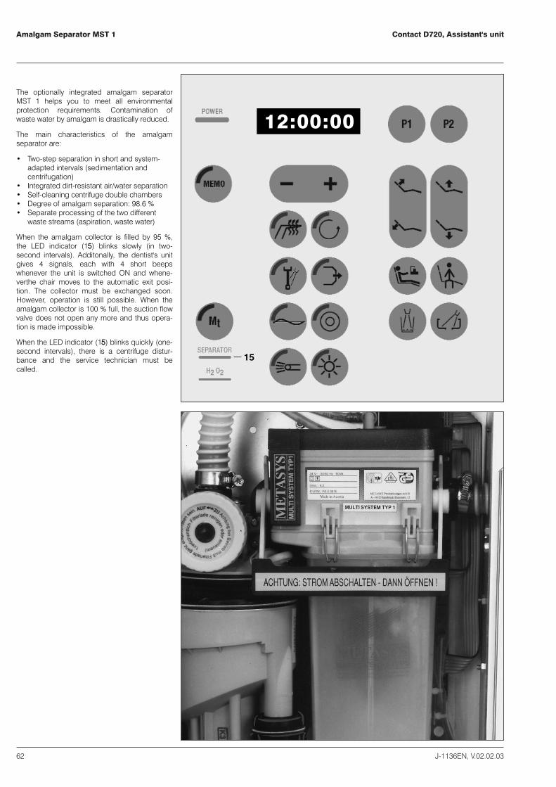
The optionally integrated amalgam separatorMST 1 helps you to meet all environmentalprotection requirements. Contamination ofwaste water by amalgam is drastically reduced.
The main characteristics of the amalgamseparator are:
� Two-step separation in short and system-adapted intervals (sedimentation andcentrifugation)
� Integrated dirt-resistant air/water separation� Self-cleaning centrifuge double chambers� Degree of amalgam separation: 98.6 %� Separate processing of the two different
waste streams (aspiration, waste water)
When the amalgam collector is filled by 95 %,the LED indicator (115) blinks slowly (in two-second intervals). Additonally, the dentist's unitgives 4 signals, each with 4 short beepswhenever the unit is switched ON and whene-verthe chair moves to the automatic exit posi-tion. The collector must be exchanged soon.However, operation is still possible. When theamalgam collector is 100 % full, the suction flowvalve does not open any more and thus opera-tion is made impossible.
When the LED indicator (115) blinks quickly (one-second intervals), there is a centrifuge distur-bance and the service technician must becalled.

Water Disinfection System WES D628Contact D720, Assistant's unit
J-1136EN, V.02.02.03 63
16
By means of the optional water disinfectionsystem WES D 628 the patient water, i.e. instru-ment spray water and mouth rinsing water, isbeing pretreated. The effective substance isH2O2 with an initial concentration of 3 % whichin the system becomes diluted to a 35 ... 50mg/l employable solution.
If the tank for the disinfectant H2O2 is almostempty, the LED indicator (1166) blinks. The tankmust be refilled with 1 liter of Formatex (OrderNo. U 4700).
If the LED indicator (1166) is constantly illumi-nated, the water disinfection system has afailure and the service technician must becalled.
In case of failure of the water disinfectionsystem, the unit is automatically switched overto normal, non-treated water and operation withthe unit can be continued.

Contact D720, Assistant's unitValve for bowl rinse
64 J-1136EN, V.02.02.03
1
3
2
Optionally, the assistant's unit can be providedwith a valve for bowl rinsing. This valve elimi-nates suction noises at the cuspidor bowl.
In order to warrant proper function of this valve,the automatic cleaning process has to beactivated at least twice a day.
The valve for bowl rinsing (11) and the controlelement (2) are integrated in the column of theassistant's unit.
For activating the automatic cleaning processpress key (3).
The manufacturer's instructions have to beadherred to.

Ritter Contact D720
Dental work placeMaintenance instructions
Ritter Concept GmbHBahnhofstraße 65, 08297 Zwönitz
Fon: 037754/13-0, Fax: 037754/13-342
e-mail: [email protected]: http://www.ritterconcept.de

ContentsContact D720, maintenance
J-1136EN, V.02.02.03 67
Contents 67
Daily 69
Weekly 73
Quarterly 75
Cleaning 84
Failure codes 85
Technical modifications reserved.

DailyContact D720, Maintenance
J-1136EN, V.02.02.03 69
Important: The instrument hoses are notto be cleaned in a thermodisinfector.The hoses can be subjected to amaximum temperature of 40°C.
Conformity with the hygienic standards as wellas good performance of the equipment arewarranted by adherring to the recommendati-onsfor disinfection, cleaning and maintenance.
Burr instruments
- Before the first treatment, let instruments runfor approx. 30 seconds to purge all spraytubes.
-Clean and maintain turbine, handpiecesand contra-angle attachments.
IImmppoorrttaanntt:: Please read the manufacturer'sinstructions for the burr instruments verycarefully.

Contact D720, Maintenance Daily
70 J-1136EN, V.02.02.03
6897
96
Conformity with the hygienic standards as wellas good performance of the equipment arewarranted by adherring to the recommendati-onsfor disinfection, cleaning and maintenance.
Burr instruments
- Before the first treatment, let instruments runfor approx. 30 seconds to purge all spraytubes.
-Clean and maintain turbine, handpiecesand contra-angle attachments.
IImmppoorrttaanntt:: Please read the manufacturer'sinstructions for the burr instruments verycarefully.
Saliva ejector, Surgical suction, Suction hand-piece
Unscrew handpiece from hose. Clean acces-sible hose ends and handpieces. Lubricate O-rings with vaseline and reassemble handpieceto the hose.
Unsuited and not permitted are cleaning agentsbased on quaternary ammonium compositions,cleaning agents containing phenol and alde-hyde as well as foam generating agents.
For dosage directions, please refer to therecommendations given for the individual clea-ning and disinfection agents.
DailyContact D720,Maintenance
J-1136EN, V.02.02.03 71
55
53
52
84
85
86
68
5
4
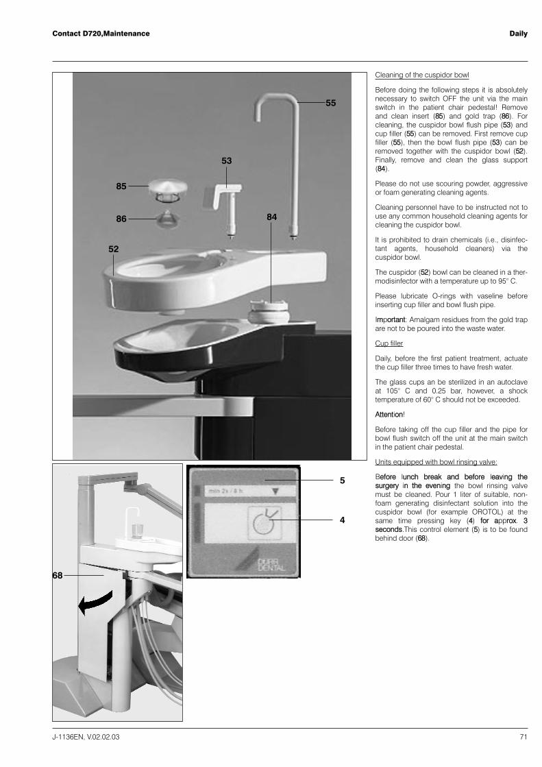
Cleaning of the cuspidor bowl
Before doing the following steps it is absolutelynecessary to switch OFF the unit via the mainswitch in the patient chair pedestal! Removeand clean insert (8855) and gold trap (8866). Forcleaning, the cuspidor bowl flush pipe (5533) andcup filler (5555) can be removed. First remove cupfiller (5555), then the bowl flush pipe (5533) can beremoved together with the cuspidor bowl (5522).Finally, remove and clean the glass support(8844).
Please do not use scouring powder, aggressiveor foam generating cleaning agents.
Cleaning personnel have to be instructed not touse any common household cleaning agents forcleaning the cuspidor bowl.
It is prohibited to drain chemicals (i.e., disinfec-tant agents, household cleaners) via thecuspidor bowl.
The cuspidor (5522) bowl can be cleaned in a ther-modisinfector with a temperature up to 95° C.
Please lubricate O-rings with vaseline beforeinserting cup filler and bowl flush pipe.
IImmppoorrttaanntt:: Amalgam residues from the gold trapare not to be poured into the waste water.
Cup filler
Daily, before the first patient treatment, actuatethe cup filler three times to have fresh water.
The glass cups an be sterilized in an autoclaveat 105° C and 0.25 bar, however, a shocktemperature of 60° C should not be exceeded.
AAtttteennttiioonn!!
Before taking off the cup filler and the pipe forbowl flush switch off the unit at the main switchin the patient chair pedestal.
Units equipped with bowl rinsing valve:
BBeeffoorree lluunncchh bbrreeaakk aanndd bbeeffoorree lleeaavviinngg tthheessuurrggeerryy iinn tthhee eevveenniinngg the bowl rinsing valvemust be cleaned. Pour 1 liter of suitable, non-foam generating disinfectant solution into thecuspidor bowl (for example OROTOL) at thesame time pressing key (44) ffoorr aapppprrooxx.. 33sseeccoonnddss.This control element (55) is to be foundbehind door (6688).

Contact D720, Maintenance Daily
72 J-1136EN, V.02.02.03
68
88 + 89
89 88
Separation filter (filter sieve)
It is recommended to wear protective gloves.
Open cover (8877) via the opening for the suctionhose (snap lock). Horizontally! take out theseparation filter container (8899) together with thefilter (filter sieve) (8888).
Lift out the separation filter (8888) from the filtercontainer (8899) and rinse the filter or, if necessary,replace the filter by a new one (Order No. F31323 for filter,Order No. F 31324 for filtercontainer).
It is not permitted to operate the aspirationsystem without separation filter.
IImmppoorrttaanntt:: The contents of the filter (amalgamparticles) are not to be poured into the wastewater.

WeeklyContact D720, Maintenance
J-1136EN, V.02.02.03 73
95 98
90 91 92
90
68
Filter drawer
The filter drawer (9922) must be inspected once aweek and exchanged if necessary (at least aftertwo or three months, Order No. F 30440, 10pieces per pack). The filter drawer is to be foundin the unit column behind door (6688) which has amagnetic lock. Unscrew cap (9900) and inspectwasher (9911). If washer is damaged, it must bereplaced (Order No. F30442). Tighten cap (99OO)again and secure tight fit.
It is not permitted to operate the aspirationsystem without filter drawer.
IImmppoorrttaanntt:: The contents of the filter drawerarenot to be poured into the waste water. Amalgamparticles are to be disposed into a sparemalgam waste container.
Unit equipped with hygiene system H1:
Exchange of the chemical cartridge
If the LED indicator (9955) blinks and a beep isheard whenever a suction hose is taken from itsholder, the chemical cartridge (9988) must beexchanged.
First, switch OFF main switch. Open door (6688) inthe unit column (magnetic lock). Press the frontlocking mechanism (9988) and horizontally takethe cartridge from its guide rails. The new, filledcartridge is placed on the guide rails, insertedand locked by pressure to the front edge of thecartridge. Turn ON main switch again. The initialcleaning program will start automatically (andlasts for approx. 20 seconds).
Contact D720, Maintenance Weekly
74 J-1136EN, V.02.02.03
129
129
6
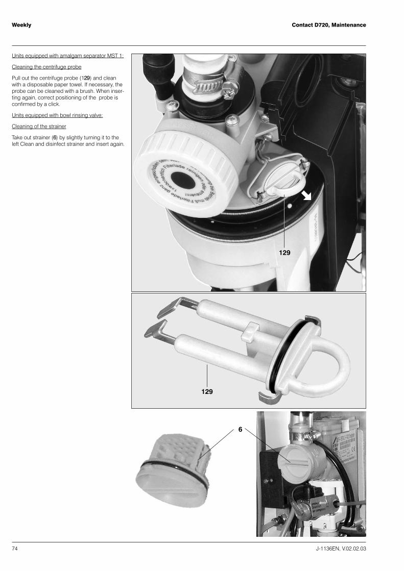
Units equipped with amalgam separator MST 1:
Cleaning the centrifuge probe
Pull out the centrifuge probe (112299) and cleanwith a disposable paper towel. If necessary, theprobe can be cleaned with a brush. When inser-ting again, correct positioning of the probe isconfirmed by a click.
Units equipped with bowl rinsing valve:
Cleaning of the strainer
Take out strainer (66) by slightly turning it to theleft Clean and disinfect strainer and insert again.

QuarterlyContact D720, Maintenance
J-1136EN, V.02.02.03 75
Check the H2O2 concentration
If the water disinfection system WES D 628 isintegrated in the dental work place, the H2O2concentration must be checked.
Operate cup filler three times. Determine theH2O2 concentration of the rinsing cup wateraccording to the instructions given for the teststicks. The test area must be dark blue(35 ... 50 mg/l). Please observe the expiry dateindicated on the package.
Test sticks (100 pieces per package) -
Order No. U 4701.
Contact D720, Maintenance Quarterly
76 J-1136EN, V.02.02.03
111
110109
112
108
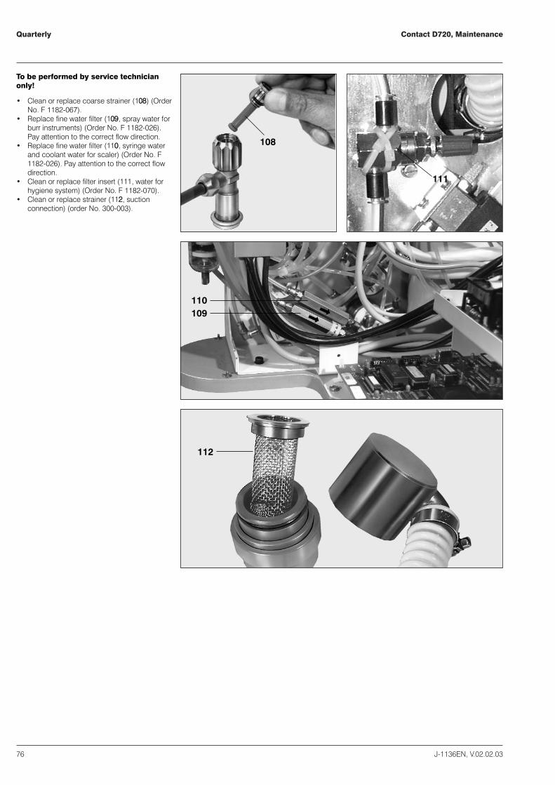
To be performed by service technicianonly!
� Clean or replace coarse strainer (110088) (OrderNo. F 1182-067).
� Replace fine water filter (110099, spray water forburr instruments) (Order No. F 1182-026).Pay attention to the correct flow direction.
� Replace fine water filter (111100, syringe waterand coolant water for scaler) (Order No. F1182-026). Pay attention to the correct flowdirection.
� Clean or replace filter insert (111111, water forhygiene system) (Order No. F 1182-070).
� Clean or replace strainer (111122, suctionconnection) (order No. 300-003).

When necessaryContact D720,Maintenance
J-1136EN, V.02.02.03 77
113
Empty turbine exhaust air oil container (111133)and replace cotton wool.
The specified obligatory protective filter (111144) atsite must be subjected to regular maintenance.Please adhere to the manufacturer's instruc-tions.

Contact D720, Maintenance When necessary
78 J-1136EN, V.02.02.03
Important: The instrument hoses are notto be cleaned in a thermodisinfector. Thehoses can be subjected to a temperatureof maximum 40° C.
44
45, 46
SterilisierenSterilize
StériliserEsterilizar
DesinfizierenDisinfectDésinfecterDesinfectar
SterilisierenSterilize
StériliserEsterilizar
DesinfizierenDisinfectDésinfecterDesinfectar
47 115 116Syringe handpiece
Sterilize syringe tip (4444) and handle (4477) withsuperheated steam not exceeding 135° C.
The handle can be removed for cleaning orsterilization. Press button (111166) and pull valvebody (111155) with hose out of the handle (4477). Donot pull hose. Turn tip (4444) slightly to separate itfrom the handle. When reassembling handleand valve body, take care that keys (4455,, 4466) onhandle point downwards and are not pressed.Push valve body into handle with activatingparts pointing downwards. The button mustjump into the groove of the handle.
Syringe tip
Due to the lime content of the water, the nozzleof the syringe tip (4444) will clog after some time.Therefore, clean nozzle from time to time withthe cleaning pin (in the accessories).
Ultrasonic scaler
� Sterilize the instrument insert of theultrasonic scaler in the autoclave with atemperature up to 135° C.
� Replace the scaler tip.
Electro-surgical unit
� Sterilize electrodes and transparent plasticprotective cap of the electro-surgicalhandpiece in the autoclave with atemperature up to 135° C.
� Disinfect electro-surgical handpiece andcable.
When necessaryContact D720, Maintenance
J-1136EN, V.02.02.03 79
SterilisierenSterilize
StériliserEsterilizar
DesinfizierenDisinfectDésinfecterDesinfectar
117 118
81
62
117117 118beschichtetcoatedsurface avec filmrecubierta
beschichtetcoatedsurface avec filmrecubierta
unbeschichtetuncoatedsurface sans filmno recubierta
unbeschichtetuncoatedsurface sans filmno recubierta
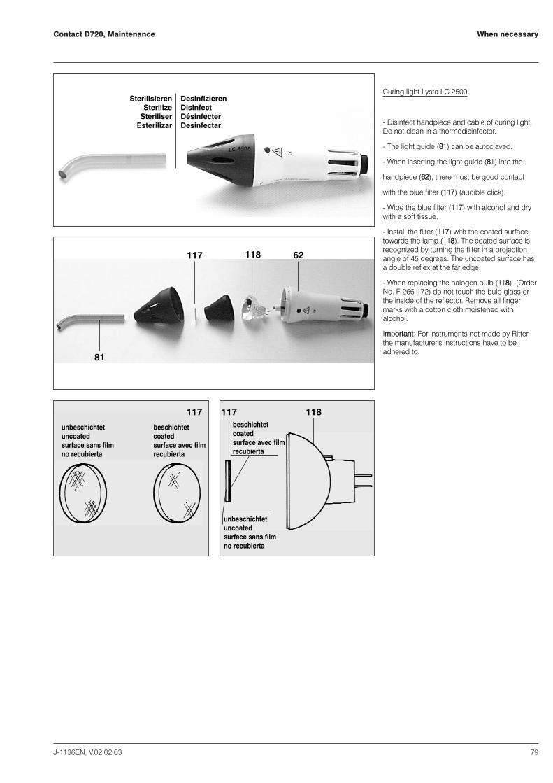
Curing light Lysta LC 2500
- Disinfect handpiece and cable of curing light.Do not clean in a thermodisinfector.
- The light guide (8811) can be autoclaved.
- When inserting the light guide (8811) into the
handpiece (6622), there must be good contact
with the blue filter (111177) (audible click).
- Wipe the blue filter (111177) with alcohol and drywith a soft tissue.
- Install the filter (111177) with the coated surfacetowards the lamp (111188). The coated surface isrecognized by turning the filter in a projectionangle of 45 degrees. The uncoated surface hasa double reflex at the far edge.
- When replacing the halogen bulb (111188) (OrderNo. F 266-172) do not touch the bulb glass orthe inside of the reflector. Remove all fingermarks with a cotton cloth moistened withalcohol.
IImmppoorrttaanntt:: For instruments not made by Ritter,the manufacturer's instructions have to beadhered to.
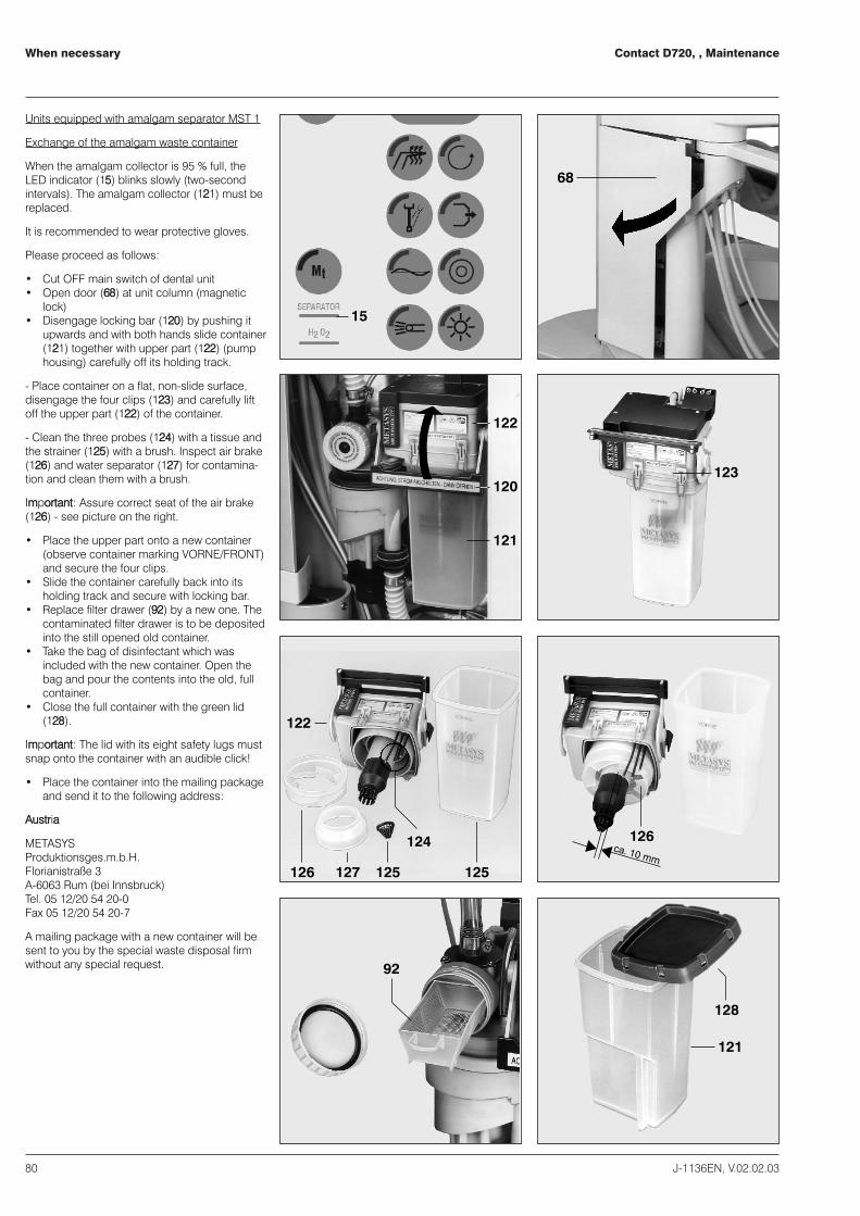
Contact D720, , Maintenance When necessary
80 J-1136EN, V.02.02.03
68
15
122
120
121
123
122
121
128
127 125 125
126
126
124
92
ca. 10 mm
Units equipped with amalgam separator MST 1
Exchange of the amalgam waste container
When the amalgam collector is 95 % full, theLED indicator (1155) blinks slowly (two-secondintervals). The amalgam collector (112211) must bereplaced.
It is recommended to wear protective gloves.
Please proceed as follows:
� Cut OFF main switch of dental unit� Open door (6688) at unit column (magnetic
lock)� Disengage locking bar (112200) by pushing it
upwards and with both hands slide container(112211) together with upper part (112222) (pumphousing) carefully off its holding track.
- Place container on a flat, non-slide surface,disengage the four clips (112233) and carefully liftoff the upper part (112222) of the container.
- Clean the three probes (112244) with a tissue andthe strainer (112255) with a brush. Inspect air brake(112266) and water separator (112277) for contamina-tion and clean them with a brush.
IImmppoorrttaanntt:: Assure correct seat of the air brake(112266) - see picture on the right.
� Place the upper part onto a new container(observe container marking VORNE/FRONT)and secure the four clips.
� Slide the container carefully back into itsholding track and secure with locking bar.
� Replace filter drawer (9922) by a new one. Thecontaminated filter drawer is to be depositedinto the still opened old container.
� Take the bag of disinfectant which wasincluded with the new container. Open thebag and pour the contents into the old, fullcontainer.
� Close the full container with the green lid(112288).
IImmppoorrttaanntt:: The lid with its eight safety lugs mustsnap onto the container with an audible click!
� Place the container into the mailing packageand send it to the following address:
AAuussttrriiaa
METASYSProduktionsges.m.b.H.Florianistraße 3A-6063 Rum (bei Innsbruck)Tel. 05 12/20 54 20-0Fax 05 12/20 54 20-7
A mailing package with a new container will besent to you by the special waste disposal firmwithout any special request.
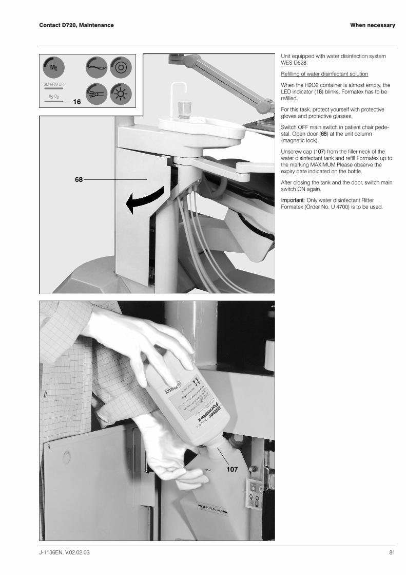
When necessaryContact D720, Maintenance
J-1136EN, V.02.02.03 81
68
16
107
Unit equipped with water disinfection systemWES D628:
Refilling of water disinfectant solution
When the H2O2 container is almost empty, theLED indicator (1166) blinks. Formatex has to berefilled.
For this task, protect yourself with protectivegloves and protective glasses.
Switch OFF main switch in patient chair pede-stal. Open door (6688) at the unit column(magnetic lock).
Unscrew cap (110077) from the filler neck of thewater disinfectant tank and refill Formatex up tothe marking MAXIMUM.Please observe theexpiry date indicated on the bottle.
After closing the tank and the door, switch mainswitch ON again.
IImmppoorrttaanntt:: Only water disinfectant RitterFormatex (Order No. U 4700) is to be used.
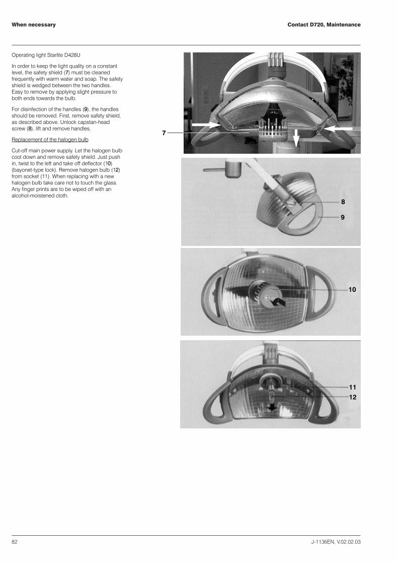
Contact D720, Maintenance When necessary
82 J-1136EN, V.02.02.03
7
8
9
10
1112
Operating light Starlite D428U
In order to keep the light quality on a constantlevel, the safety shield (77) must be cleanedfrequently with warm water and soap. The safetyshield is wedged between the two handles.Easy to remove by applying slight pressure toboth ends towards the bulb.
For disinfection of the handles (99), the handlesshould be removed. First, remove safety shield,as described above. Unlock capstan-headscrew (88), lift and remove handles.
Replacement of the halogen bulb
Cut-off main power supply. Let the halogen bulbcool down and remove safety shield. Just pushin, twist to the left and take off deflector (1100)(bayonet-type lock). Remove halogen bulb (1122)from socket (1111). When replacing with a newhalogen bulb take care not to touch the glass.Any finger prints are to be wiped off with analcohol-moistened cloth.
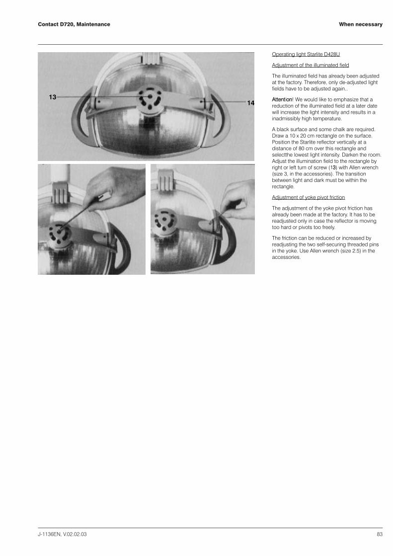
When necessaryContact D720, Maintenance
J-1136EN, V.02.02.03 83
1314
Operating light Starlite D428U
Adjustment of the illuminated field
The illuminated field has already been adjustedat the factory. Therefore, only de-adjusted lightfields have to be adjusted again..
AAtttteennttiioonn!! We would like to emphasize that areduction of the illuminated field at a later datewill increase the light intensity and results in ainadmissibly high temperature.
A black surface and some chalk are required.Draw a 10 x 20 cm rectangle on the surface.Position the Starlite reflector vertically at adistance of 80 cm over this rectangle andselectthe lowest light intensity. Darken the room.Adjust the illumination field to the rectangle byright or left turn of screw (1133) with Allen wrench(size 3, in the accessories). The transitionbetween light and dark must be within therectangle.
Adjustment of yoke pivot friction
The adjustment of the yoke pivot friction hasalready been made at the factory. It has to bereadjusted only in case the reflector is movingtoo hard or pivots too freely.
The friction can be reduced or increased byreadjusting the two self-securing threaded pinsin the yoke. Use Allen wrench (size 2.5) in theaccessories.
Contact D720, Maintenance
84 J-1136EN, V.02.02.03
Cleaning
Cleaning of the dental work place
Clean painted and plastic parts with water andsoap.
For disinfection and cleaning only use thoseagents recommended by us, for exampleEsemfix, Mikrozid Liquid, Incidin or Incidur.
We would like to emphasize that the manufactu-rer's instructions must be strictly adherred towhen handling disinfectants. Otherwise, even ifapplying the recommended agents, discoloringof covers cannot be excluded entirely.
When wearing disposable gloves made of latex,discoloring of the plastic parts may occur. Nosuch discoloring was registered with disposablegloves made of silicone, vinyl or polyethylene.
Do not use any metal polish.
Dry drops of water, blood or chemicals imme-diately.
Cleaning of upholstery and covers
Use only warm water and soap. Remove soapresidues with a damp sponge. Dry with a softcloth.

Failure codesContact D720, Maintenance
J-1136EN, V.02.02.03 85
12 : 00 : 00
130
131
132
Under certain circumstances the equipment willgive optical and/or acoustic signals which allowtracing of the failure.
Optical signals:
LLEEDD ((113311)) bblliinnkkss iinn ttwwoo--sseeccoonndd iinntteerrvvaallss::
� suction still working - amalgam separatorhas reached a filling level of 95 %.
� suction not working - amalgam separator100 % full.
This signal is coupled with an acoustic signal.
LLEEDD ((113311)) bblliinnkkss iinn oonnee--sseeccoonndd iinntteerrvvaallss::
Centrifuge failure of amalgam separatorcall service technician.
LLEEDD bblliinnkkss ttwwiiccee sshhoorrttllyy iinn ffoouurr--sseeccoonndd iinntteerrvvaallss::
Refill water disinfectant solution.
LLEEDD ((113322)) ccoonnssttaannttllyy iilllluummiinnaatteedd::
Failure of the water disinfection system,
no safe function, - call service technician.
LLEEDD ((113322)) bblliinnkkss sslloowwllyy ((33 sseeccoonnddss oonn 00..55sseeccoonnddss ooffff))::
Incorrect dosage, no safe function - call servicetechnician.
SSiiggnnaall iinn DDiissppllaayy ((113300))
� SSIISSxx - xx stands for a figure between 1 and 6:Safety stop activated - possibly one of theswitches blocked (please refer to operatinginstructions "patient chair") or call servicetechnician.
� SSiixxaakkttiivv - x stands for a figure between 1and 6: safety stop activated during chairmovement - eliminate interferece.
This optical signal is coupled with an acousticsignal.
Acoustic signals:
LLoonngg bbeeeepp wwhheenn iinniittiiaattiinngg cchhaaiirr mmoovveemmeennttoorr dduurriinngg cchhaaiirr mmoovveemmeenntt::
One safety stop was activated, see opticalsignal in display.
FFoouurr ggrroouuppss ooff ffoouurr sshhoorrtt bbeeeeppss aafftteerr aaccttiivvaattiinnggaanndd dduurriinngg cchhaaiirr mmoovveemmeenntt ttoo eexxiitt ppoossiittiioonn::
Amalgam separator has reach a filling level of95 %, see optical blinking signals.

Contact D720, MaintenanceNotes
86 J-1136EN, V.02.02.03


![1350 ritter[1]](https://static.fdocuments.us/doc/165x107/558a55ded8b42a88468b458c/1350-ritter1.jpg)