RITES LIMITED Dist. Birbhum, West Bengal. PART-1 TECHNICAL BID CONTENTS Section-1 : Notice Inviting...
94
Signature of the tenderer Under seal of the firm 1 RITES LIMITED OPEN TENDER NOTICE No. 26/OT/E.Rly-BHP/Gitanjali- RPF Office/2012 Dated 24.05.2012 Tender and Contract document for Construction of RPF Office, GRP Barrack & other establishment in connection with construction of Gitanjali Museum at Bolpur, Dist. Birbhum, West Bengal. PART-1 TECHNICAL BID CONTENTS Section-1 : Notice Inviting Tender and Instructions to Tenderers Section-2 : Tender and Contract Form Section-3 : Special Conditions of Contract Section-4 : Schedule A to F Section-5: Technical Specifications Section-6: Drawings Section-7: General Conditions of Contract PART- 2 FINANCIAL BID SCHEDULE (BILL) OF QUANTITIES Issued to (name of Tenderer):________________________________________________ Address of tenderer: _________________________________________________ Signature of officer issuing the documents_____________ Designation ____________________ Date of Issue_________________ RITES Ltd. (A Govt. of India Enterprise) Kolkata Project Office 56, C.R. Avenue, 2 nd Floor Kolkata-700 012 e. mail: [email protected] Phone No.: 033-22367118/7146/7162/7143(Fax)
Transcript of RITES LIMITED Dist. Birbhum, West Bengal. PART-1 TECHNICAL BID CONTENTS Section-1 : Notice Inviting...

Signature of the tenderer
Under seal of the firm 1
RITES LIMITED
OPEN TENDER NOTICE No. 26/OT/E.Rly-BHP/Gitanjali-
RPF Office/2012 Dated 24.05.2012
Tender and Contract document for Construction of RPF Office, GRP Barrack
& other establishment in connection with construction of Gitanjali Museum at
Bolpur, Dist. Birbhum, West Bengal.
PART-1
TECHNICAL BID
CONTENTS
Section-1 : Notice Inviting Tender and Instructions to Tenderers
Section-2 : Tender and Contract Form
Section-3 : Special Conditions of Contract
Section-4 : Schedule A to F
Section-5: Technical Specifications
Section-6: Drawings
Section-7: General Conditions of Contract
PART- 2
FINANCIAL BID
SCHEDULE (BILL) OF QUANTITIES
Issued to (name of Tenderer):________________________________________________
Address of tenderer: _________________________________________________
Signature of officer issuing the documents_____________
Designation ____________________
Date of Issue_________________
RITES Ltd. (A Govt. of India Enterprise)
Kolkata Project Office
56, C.R. Avenue, 2nd Floor Kolkata-700 012
e. mail: [email protected]
Phone No.: 033-22367118/7146/7162/7143(Fax)

Signature of the tenderer
Under seal of the firm 2
RITES LTD.
(A Govt. of India Enterprise)
REGIONAL PROJECT OFFICE, 56, C.R. Ave. (2nd fl),
Kolkata-12
Phone No. 033-2236 7118/46/62 FAX-033 2236 7143
NIT No. 26/OT/E.Rly-BHP/Gitanjali-RPF Office/2012
Dated 24.05.2012
General Manager (Projects), RITES Ltd. invites sealed
tenders for ‘Construction of RPF Office, GRP Barrack &
other establishment in connection with construction of
Gitanjali Museum at Bolpur, Dist. Birbhum, W.B’.
Estimated Cost: Rs76.26 lakh (Approx), EMD:
Rs.76,300/- Completion period: 04 (Four) months. Sale of
Tender Documents: 25.05.2012 to 05.06.2012. Last date of Submission of Tender: 07.06.2012 up to 14.00 Hrs.
Date of opening of Tender: From 14.30 Hrs on 07.06.2012.
Tender documents can be purchased from the above address
at a cost of Rs.5,000/- in the form of DD/PO/BC drawn on
any Schedule Bank in favour of RITES Ltd., payable at
Kolkata. For complete Tender Documents including
qualifying criteria etc. please visit: (www.rites.com) or
contact this office. Addendum/corrigendum, if any, would
be hoisted on the websites only.
Signature of the tenderer
Under seal of the firm 3
PART -1
TECHNICAL BID
SECTION-1
NOTICE INVITING TENDER & INSTRUCTION TO TENDERERS

Signature of the tenderer
Under seal of the firm 4
SECTION 1
NOTICE INVITING TENDER AND INSTRUCTIONS TO TENDERERS
1.0 GENERAL
1.1 Tender Notice
Tenders are invited by RITES Ltd., a Public Sector Enterprise under the Ministry of Railways,
acting for and on behalf of E.Rly as an Agent/Power of Attorney Holder, from working
contractors (including contractors who have executed works within the last five years reckoned
from the scheduled date of opening of tender) of Railways, CPWD, MES, DOT, RITES, State
PWD or any other Central / State Government Undertaking, Municipal Body, Autonomous Body
of Central/State Governments or Public Ltd., Co. listed on BSE/NSE for the work of “
Construction of RPF Office, GRP Barrack & other establishments at Bolpur, Dt-Birbhum.WB”
(Note : Throughout these bidding documents, the terms ‘bid’ and ‘tender’ and their derivatives are
synonymous).
1.2 Estimated Cost of Work
The work is estimated to cost Rs 76,26,092.40(Rupees Seventy six lakh twenty six thousand
ninety two and paise forty only). This Estimate, however, is given merely as a rough guide.
1.3 Time for Completion
The time allowed for completion will be 04 months from the date of start which is defined in
Schedule F under Clause 5.1a of Clauses of Contract.
1.4 Brief Scope of Work Construction of RCC double storied building with electrification
work
1.5 Availability of Site
The site for the work is available
2.0 QUALIFICATION CRITERIA TO BE SATISFIED
2.1 The Qualification Criteria to be satisfied are given at Annexure I enclosed.
2.2 The Qualification Criteria to be satisfied will depend on the category of works, whether
Normal or Large. The work for which the Tender is being invited falls under the
category of -Normal
2.3 The Qualification Criteria to be satisfied will also depend on whether the Work falls in
Normal area or Difficult area. The work for which this Tender has been invited falls
under -Normal area
2.4 In this Tender Joint Venture is not allowed.
2.5 The documents to be furnished by the Bidder to prove that he is satisfying the
Qualification Criteria laid down should all be in the Bidder’s name, except in cases where
though the name has changed, the owners continued to remain the same and in cases of
amalgamation of entities.
3.0 FORMAT AND CHECK LIST FOR SUBMISSION OF INFORMATION ON
QUALIFICATION CRITERIA

Signature of the tenderer
Under seal of the firm 5
3.1 Other than Joint Ventures
The Tenderer shall furnish a Letter of Transmittal as given in Annexure II A enclosing
the documents mentioned therein/listed in para 1(a) of Annexure IA.
4.0 CONTENTS OF TENDER DOCUMENT
4.1 Each set of Tender or Bidding Document will comprise the Documents listed below and
addenda issued in accordance with para 7 :
PART – 1 :- Technical Bid Packet (Read with Correction Slip Nos.1 to _____)
Section 1 Notice Inviting Tender and Instructions to Tenderers.
Section 2 Tender and Contract Form.
Section 3 Special Conditions.
Section 4 Schedules A to F
Section 5 Technical Specifications
Section 6 Drawings -Nil
PART – 2 :- Financial Bid Packet
Schedule of Quantities (Bill of Quantities)
PART – 3:- General Conditions of Contract (read with correction Slip Nos. 1 to ________)
Section 7 Conditions of Contract
Section 8 Clauses of Contract
Section 9 RITES Safety Code
Section 10 RITES Model Rules for protection of Health and Sanitary arrangements
for Workers
Section 11 RITES Contractor’s Labour Regulations
4.2 General Conditions of Contract (Compilation of Sections 7 to 11) with upto date
correction slips is also available in RITES website <www.rites.com>
5.0 ISSUE OF TENDER DOCUMENT
5.1 A complete set of Tender Document (Technical and Financial Bid) described in Para 4.1
above can be seen in the office of the General Manager (Projects), 56, C.R. Avenue,
2nd Floor, Kolkata – 700 012 between hours of 11.00 AM and 4.00 PM every day except
on Saturdays, Sundays and Public Holidays.
5.2 One set of Tender Document may be purchased from the office of the General Manager
(Projects); 2nd floor, 56-C.R.Avenue;Kolkata-700012 from 25.05.2012 to 05.06.2012 for a
non refundable fee per set of Rs.5,000/- (Rupees five thousand only) in the form of
Demand Draft/ Pay Order/ Banker’s cheque drawn on any Scheduled Bank payable at
Kolkata in favour of RITES Ltd., on submission of an application.
5.3 Tender Documents including drawings can also be downloaded from RITES Website
(www.rites.com) and in such a case, the Tenderer shall deposit the cost of tender
documents along with submission of tender, failing which his tender shall not be opened.
Signature of the tenderer
Under seal of the firm 6
The cost of tender documents shall be deposited in the form of a separate Banker’s cheque
/ Demand Draft / Pay Order and enclosed in the envelope containing the Earnest Money
Deposit. The amendments / clarifications to the Tender documents will also be available
on the above website.
5.4 Tender Documents downloaded from RITES website shall be considered valid for
participating in the tender process. During the scrutiny of downloaded tender document,
if any modification / correction etc. is noticed as compared to the original documents
posted on the website, the bid submitted by such a Tenderer is liable to be rejected. In
case the bid of a Tenderer who has downloaded the document from website is accepted
the contract shall be executed in the original / manual tender document issued by the
concerned RITES officer.
5.5 Clarifications on Tender Documents
A prospective Tenderer requiring any clarification on the Tender Document may notify
Sibesh Ghosal, SDGM/Civil (The official nominated for this purpose) in writing or by
telefax/ or by E-mail at the following Postal Address/ Fax No./E-mail address: Office of
the General Manager(P);2nd floor-Metro Railway Service Building;56-
C.R.Avenue;Kolkata-700012 /033-22367143/[email protected]
In cases where Pre-Bid Meeting is not proposed to be held, request for clarifications
including request for Extension of Time for submission of Bid, if any, must be received
not later than 10 (ten) days prior to the deadline for submission of tenders. Details of such
questions raised and clarifications furnished will be uploaded in RITES website without
identifying the names of the Bidders who had raised the questions. Any modification of
the Tender Document arising out of such clarifications will also be uploaded on RITES
website only.
In cases where Pre-Bid Meeting is proposed to be held, provisions in para 6.0 below may
be referred to.
6.0 PRE-BID MEETING -NO
7.0 AMENDMENT OF TENDER DOCUMENT
7.1 Before the deadline for submission of tenders, the Tender Document may be modified by
RITES Ltd. by issue of addenda/corrigendum. Issue of addenda / corrigenda will however
be stopped 7 days prior to the deadline for submission of tenders as finally stipulated.
7.2 Addendum/corrigendum, if any, will be hosted on website only and shall become a part of
the tender document. All Tenderers are advised to see the website for addendum/
corrigendum to the tender document which may be uploaded upto 7 days prior to the
deadline for submission of Tender as finally stipulated.
7.3 To give prospective Tenderers reasonable time in which to take the addenda/ corrigenda
into account in preparing their tenders, extension of the deadline for submission of tenders
may be given as considered necessary by RITES.

Signature of the tenderer
Under seal of the firm 7
8.0 TENDER VALIDITY
8.1 The Tender shall be valid for a period of 90 days from the due date for submission of
Tender or any extended date as indicated in sub para below.
8.2 In exceptional circumstances, during the process of evaluation of tenders and prior to the
expiry of the original time limit for Tender Validity, the Employer may request that the
Tenderers may extend the period of validity for a specified additional period. The request
and the tenderer’s response shall be made in writing. A Tenderer may refuse the request
without forfeiting his Earnest Money. A Tenderer agreeing to the request will not be
permitted to modify his Financial Bid to a higher amount but will be required to extend
the validity of the Earnest Money for the period of the extension.
9.0 EARNEST MONEY
9.1 The Tender should be accompanied by Earnest Money of Rs. 76,300/- (Rupees seventy
six thousand three hundred only) in any of the forms given below:-
Banker’s Cheque / Pay Order/ Demand Draft payable at Kolkata, drawn in favour of
RITES Ltd.
9.2 Any Tender not accompanied by Earnest Money in an acceptable form shall be rejected by
the Employer as non-responsive.
9.3 Refund of Earnest Money:
a) Single Packet System
After evaluation of the Financial Bids, the Earnest Money of unsuccessful Tenderers will
be returned without interest within 28 days of the end of Tender Validity Period subject to
provisions of Para 9.4 (b).
9.4 The Earnest Money is liable to be forfeited
a) if after bid opening, but before expiry of bid validity or issue of Letter of
Acceptance, whichever is earlier, any Tenderer
i) withdraws his tender or
ii) makes any modification in the terms and conditions of the tender which are
not acceptable to the Employer.
b) in case any statement/information/document furnished by the Tenderer is found to
be incorrect or false.
c) in the case of a successful Tenderer, if the Tenderer
i) fails to furnish the Performance Guarantee within the period specified under
Clause 1 of “Clauses of Contract”. or
ii) fails to commence the work without valid reasons within the period as
specified in Schedule F after the date of issue of Letter of Acceptance or
from the first date of handing over of the site, whichever is later.

Signature of the tenderer
Under seal of the firm 8
In case of forfeiture of E.M. as prescribed hereinabove, the Tenderer shall not be allowed
to participate in the retendering process of the work.
10.0 ALTERNATIVE PROPOSALS BY THE TENDERERS
The Tenderers shall submit offers which comply strictly with the requirements of the
Tender Document as amended from time to time as indicated in Para 7.0 above.
Alternatives or any modifications shall render the Tender invalid.
11.0 SUBMISSION OF TENDER
11.1 Two Packet System and Single Packet System: THIS TENDER IS SINGLE PACKET
SYSTEM
(a) Two Packet System
The tenderer shall submit the Tender in original in two packets as under:-
PACKET A :- TECHNICAL BID
Envelope 1 Earnest Money & Cost of Tender Document if the bid is
submitted on the document downloaded from RITES
website
Envelope 2 “Authority to Sign”, ‘Integrity Pact’ (when applicable) and
Qualification Information along with all enclosures /
documents as per Letter of Transmittal/ Checklist given in
Annexure II A/ II B (L)/IIB(N). As regards “Authority to
Sign” Para 11.2 below may be referred to. As regards
‘Integrity Pact’, para 11.7 below may be referred to.
Technical Bid (Part 1 and Part 3) (Refer Para 4.1) including
signature on Tender Form (Section 2) duly witnessed after
filling up blanks therein.
Each page of the above documents including all Drawings
should bear the dated initials of the Tenderer along with the
seal of the Company, in token of confirmation of having
understood the Contents.
PACKET B :- FINANCIAL BID
Envelope 3 Schedule/Bill of Quantities.
Each page of the Financial Bid (Part 2 – Refer Para 4.1) should be signed by the Tenderer
along with the seal of the company. In the last page of Financial Bid, at the end, the
Tenderer should sign in full with the name of the Company, Seal of the Company and
Date.
All rates and amounts, both in figures and words, must be written in indelible ink. Each
Correction, Cutting, Addition and overwriting should be initialed by the Tenderer.

Signature of the tenderer
Under seal of the firm 9
The rates must be quoted in decimal coinage. Amounts must be quoted in full rupees by
ignoring fifty paise and less and considering more than fifty paise as rupee one. If the
same item figures in more than one section/part of Schedule of Quantities, the Tenderer
should quote the same rate for that item in all sections/parts. If different rates are quoted
for the same item, the least of the different rates quoted only shall be considered for
evaluation of that item in all sections/parts of the Schedule of Quantities.
Instructions contained in subsequent Para 17.6 (a) on “Item rate tender” and 17.6 (b) on
“Percentage rate tender” may be carefully studied and complied with.
b) Single Packet System : Both Technical Bid (including signature on Tender Form in
Section 2 duly witnessed) and Financial Bid Documents will be submitted in one Packet.
Precautions as described above for Two Packet System shall be observed by the tenderers.
11.2 Authority to Sign
a) If the applicant is an individual, he should sign above his full type written name
and current address.
b) If the applicant is a proprietary firm, the Proprietor should sign above his full type
written name and the full name of his firm with its current address.
c) If the applicant is a firm in partnership, the Documents should be signed by all the
partners of the firm above their full type written names and current addresses.
Alternatively the Documents should be signed by the person holding Power of
Attorney for the firm in the Format at Annexure IV.
d) If the applicant is a limited Company, or a Corporation, the Documents shall be
signed by a duly authorized person holding Power of Attorney for signing the
Documents in the Format at Annexure IV.
11.3 Items to be kept in mind while furnishing details
While filling in Qualification Information documents and the Financial Bid, following
should be kept in mind:
i) There shall be no additions or alterations except those to comply with the
instructions issued by the Employer or as necessary to correct errors, if any, made
by the Tenderers.
ii) Conditional Offer/ Tender will be rejected. Unconditional rebate/ discounts in the
Financial offer will however be accepted.
iii) The Employer reserves the right to accept or reject any conditional
rebate/discounts. While evaluating the Bid Price, the conditional rebates/discounts
which are in excess of the requirements of the bidding documents or otherwise
result in accrual of unsolicited benefits to the Employer, shall not be taken into
account.
11.4 Sealing and Marking of Tenders [This tender is single packet system]

Signature of the tenderer
Under seal of the firm 10
11.4.1 Two Packet System
(a) PACKET A – TECHNICAL BID
Envelopes 1 & 2 as described in Para 11.1 (a) above should be sealed separately
superscribing “Technical Bid” with Envelope Number, Name of the work and Name
of the tenderer. In addition, the following should also be superscribed on the respective
envelopes.
Envelope 1 i) Earnest Money
ii) Cost of Tender Document if the Bid is submitted
on the document downloaded from RITES website.
Envelope 2 i) Authority to Sign, ‘Integrity Pact’ (when
applicable as per para 11.7 below) and Qualification
Information/ documents as per checklist in
Annexure IIA / IIB(L)/ II B (N).
ii) Technical Bid including Drawings
Both the envelopes should be put in a packet which should be sealed. The following
should be superscribed on the packet:
i) Packet A – Technical Bid
ii) Name of the Work
iii) Name of the Tenderer
(b) PACKET B – FINANCIAL BID
Envelope 3 – Financial Bid should be put in Packet B which should be sealed. The
following should be superscribed on the packet.
i) Packet B - Financial Bid
ii) Name of the work
iii) Name of the tenderer
(c) Both packets A and B should be put inside an outer envelope and sealed. This envelope
should be superscribed with the following details:
i) Tender for (Name of work)
ii) Tender number
iii) Date and time of opening of Tender
iv) From (Name of Tenderer)
v) Addressed to ---- (RITES Officer inviting the Tender)

Signature of the tenderer
Under seal of the firm 11
11.4.2 Single Packet System
Two envelopes of Technical Bid and one of Financial Bid shall be made out as stipulated
in Para 11.4.1 (a) and (b) above with the Name of the work and Name of the Tenderer
superscribed on each of the envelopes. All the three envelopes shall be put in a Single
Packet which shall be superscribed in the same manner as given in Para 11.4.1 (c) above.
11.4.3 If the envelopes and packets are not superscribed and sealed as indicated in Paras 11.4.1/
11.4.2 above, the Employer will assume no responsibility for the misplacement or
premature opening of the Tender.
11.5 Deadline for submission of Tender
11.5.1 Tenders must be received by the Employer at the following address not later than 14.00
Hrs. on 07.06.2012. In the event of the specified date for the submission of the Tender
being declared a holiday due to Strike/Bandh or on any account by the Employer, the
Tenders will be received up to the appointed time on the next working day.
Address for submission of Tender: Office of the General Manager (Projects),
RITES Limited,
56, C.R. Avenue, 2nd Floor,
Kolkata – 700 012.
11.5.2 The Employer may extend the deadline for submission of Tenders by issuing an
amendment in writing in accordance with Para 7.3 in which case all rights and obligations
of the Employer and the Tenderer previously subject to the original deadline will be
subject to new deadline.
11.6 Late Tender / Delayed Tender
Any Tender received by the Employer after the specified date and time of receipt of
Tender will be returned unopened to the Tenderer.
11.8 Modification and Withdrawal of Bids
11.8.1 Tenderers may modify or withdraw their bids by giving notice in writing before the
deadline prescribed in para 11.5 for submission of Bids.
11.8.2 Each modification or withdrawal notice shall be prepared, sealed, marked and delivered in
accordance with paras 11.1, 11.2 and 11.4 with the outer envelopes additionally marked
‘Modification’ or ‘Withdrawal’ as appropriate.
The envelopes for modifications on ‘Technical Bid’ and ‘Financial Bid’ shall be submitted
in separate sealed envelopes and marked as ‘Modifications of Technical Bid’ or
‘Modifications of Financial Bid’ as the case may be.
11.8.3 No bid may be modified after the deadline for submission of Bids except as indicated
below. If a Bidder makes a suo moto offer of rebate / discount in his Financial Bid after
the deadline for submission of Bids, such offer will not be considered for Financial
evaluation of Tenders. But if the Tenderer is successful in the Bid based on his original
offer without considering the suo moto offer, the rebate / discount offered will be taken
into account for incorporation in the Contract Agreement.

Signature of the tenderer
Under seal of the firm 12
11.8.4 Withdrawal or modification of a Bid, subject to provisions in Para 11.8.3 above, after the
deadline for submission of Bids shall result in forfeiture of the Earnest Money.
12.0 TENDER OPENING, EVALUATION AND CLARIFICATIONS OF
APPLICATIONS
12.1 The Employer will open all the Tenders received (except those received late or delayed)as
described in para 12.2/12.3 below, in the presence of the Tenderers or their representatives
who choose to attend at 14.30 Hrs. on 07.06.2012 in the office of the General Manager
(Projects), RITES Ltd. In the event of the specified date of the opening being declared a
holiday by the Employer, the Tenders will be opened at the appointed time and location on
the next working day.
12.2 Single Packet System
(a) Envelope 1 of all the Tenders will be opened first and checked. If the Earnest Money
furnished is not for the stipulated amount or is not in an acceptable form and where
applicable the Cost of Tender Document has not been furnished for the correct amount
and in an acceptable form, the remaining envelopes will be returned to the tenderer
concerned unopened at the time of opening of the Tender itself. The Envelopes no. 2 of
Technical Bid and no. 3 of Financial Bid of other Tenderers who have furnished Earnest
Money and where applicable the Cost of Tender Document, in acceptable form will then
be opened. The Tenderer’s name, the presence of Earnest Money, the Authority to Sign
the Tender, amount quoted and such other details as the Employer may consider
appropriate will be announced by the Employer.
13.0 INSPECTION OF SITE BY THE TENDERERS
Tenderers are advised to inspect and examine the site and its surroundings and satisfy
themselves before submitting their Tenders, as to the nature of the ground and sub-soil (as
far as is practicable), the form and nature of the site, the means of access to the site, the
accommodation they may require and in general shall themselves obtain all necessary
information as to risks, contingencies and other circumstances which may influence or
affect their Tender. A Tenderer shall be deemed to have full knowledge of the site
whether he inspects it or not and no extra charges consequent on any misunderstanding or
otherwise shall be allowed. The Tenderer shall be responsible for arranging and
maintaining at his own cost all materials, tools & plants, water, electricity, access,
facilities for workers and all other services required for executing the work unless
otherwise specifically provided for in the contract documents. Submission of a tender by
a Tenderer implies that he has read this notice and all other contract documents and has
made himself aware of the scope and specifications of the work to be done and of
conditions and rates at which stores, tools and plant etc. will be issued to him by the
Employer and local conditions and other factors having a bearing on the execution of the
work.
14.0 EMPLOYER’S RIGHT ON ACCEPTANCE OF ANY TENDER
(i) If required, the Employer may ask any Tenderer the breakdown of unit rates. If the
Tenderer does not submit the clarification by the date and time set in the Employers
request for clarification, such Tender is likely to be rejected.
(ii) The competent authority on behalf of the Employer does not bind himself to accept
the lowest or any other Tender and reserves to himself the authority to reject any or all
Signature of the tenderer
Under seal of the firm 13
the Tenders received without the assignment of any reason. All Tenders in which any
of the prescribed conditions is not fulfilled or any condition is put forth by the
Tenderer shall be summarily rejected.
15.0 CANVASSING PROHIBITED
Canvassing whether directly or indirectly, in connection with tenders is strictly prohibited
and the tenders submitted by the Contractors who resort to canvassing will be liable to
rejection.
16.0 EMPLOYER’s RIGHT TO ACCEPT WHOLE OR PART OF THE TENDER
The competent authority on behalf of the Employer reserves to himself the right of
accepting the whole or any part of the tender and the Tenderer shall be bound to perform
the same at the rates quoted.
17.0 MISCELLANEOUS RULES AND DIRECTIONS
17.1 The Tenderer shall not be permitted to tender for works if his near relative is posted as
Associated Finance Officer between the grades of AGM(F) and J.M (F) in the concerned
SBU Unit of RITES or as an officer in any capacity between the grades of GGM/GM and
Engineer (both inclusive) of the concerned SBU of the Employer. He shall also intimate
the names of persons who are working with him in any capacity or are subsequently
employed by him and who are near relatives to any Gazetted officer in the organization of
the Employer. Any breach of this condition by the Tenderer would render his Tender to be
rejected.
No Engineer of Gazetted rank or other Gazetted Officer employed in Engineering or
Administrative duties in an Engineering Department of the Organisation of the Employer
is allowed to work as a contractor for a period of one year after his retirement from the
Employer’s service without the previous permission of the Employer in writing. The
contract is liable to be cancelled if either the Contractor or any of his employees is found
any time to be such a person who had not obtained the permission of the Employer as
aforesaid before submission of the tender or engagement in the Contractor’s service.
17.2 If required by the Employer, the Tenderers shall sign a declaration under the officials
Secret Act 1923, for maintaining secrecy of the tender documents drawings or other
records connected with the work given to them. The unsuccessful Tenderers shall return
all the drawings given to them.
17.3 Use of correcting fluid anywhere in tender document is not permitted. Such tender is liable
for rejection.
17.4 a) In case of percentage Rate Tender only percentage quoted shall be considered. Any
tender containing item rates is liable to be rejected. Percentage quoted by the Tenderer in
percentage rate tender shall be accurately filled in figures and words so that there is no
discrepancy. If, for any Schedule in Financial Bid, the total amount has been indicated by
the Tenderer and if discrepancy is noticed in the percentages quoted in words and figures,
then the percentage which corresponds with the total amount, shall, unless otherwise
proved be taken as correct. If the total amount is not worked out or if worked out, it does
not correspond with the percentages written either in figures or in words, then the
percentage quoted by Tenderer in words shall be taken as correct. When the percentages
quoted by the Tenderer in figures and in words tally but the total amount is not worked out
correctly, the percentage quoted by the Tenderes shall be taken as correct, unless proved
otherwise and the total amount worked out accordingly.
Signature of the tenderer
Under seal of the firm 14
17.5 (a) In Percentage Rate Tender, the Tenderer shall quote percentage below / above (in figures
as well as in words) at which he will be willing to execute the work. He shall also work
out the total amount of his offer and the same should be written in figures as well as in
words in such a way that no interpolation is possible. In case of figures, the word “Rs”
should be written before the figure rupees and word ‘P’ after the decimal figures
(eg.) Rs.2.15 P and in case of words the word “Rupees” should precede and the word
“Paisa” should be written at the end.
17.6 Sales-tax/VAT (except Service Tax), purchase tax, turnover tax or any other tax/ Cess on
material, labour and Works in respect of this Contract shall be payable by the Contractor
and the Employer will not entertain any claim whatsoever in respect of the same.
However, in respect of Service Tax, same shall be paid by the Contractor to the concerned
department on demand and it will be reimbursed to him by the Engineer-in-Charge after
satisfying that it has been actually and genuinely paid by the Contractor.
17.7 Each Bidder shall submit only one Bid either as an individual or as a Proprietor in a
Proprietary firm or as a Partner in a Partnership firm or as a Director of a limited
Company/Corporation . Any Bidder who has submitted a Bid for a work, shall not be a
witness for any other Bidder for the same work. Failure to observe the above stipulations
would render all such Tenders submitted as a Bidder and / or as a witness, liable to
summary rejection.
17.8 The Contractor shall be fully responsible for all matters arising out of the Performance of
the Contract and shall, at his own expense, comply with all laws/ acts/ enactments/
orders/ regulations/ obligations whatsoever of the Government of India, State
Government, Local Body and any Statutory Authority.
18.0 SIGNING OF CONTRACT AGREEMENT
18.1 The Tenderer whose tender has been accepted will be notified of the award by the
Employer by issue of a `Letter of Acceptance’ ‘ prior to expiration of the Bid Validity
period, in the form at Annexure VI.
The Letter of Acceptance will be sent to the Contractor in two copies one of which he
should return promptly, duly signed and stamped. The Letter of Acceptance will be a
binding Contract between the Employer and the Contractor till the formal Contract
Agreement is executed.
18.2 Within the period as specified in Clause 1 of `Clause of Contract’, of the date of issue of
Letter of Acceptance, the successful Tenderer shall deliver to the Employer, Performance
Guarantee and Additional Performance Guarantee (where applicable) in the format
prescribed.
18.3 The Tenderer whose Tender is accepted shall be required to submit at his cost stamp
papers of appropriate value as per the provisions of Indian Stamp Act within 15 days of
the date of issue of Letter of Acceptance.
18.4 At the same time the Employer notifies the successful Tenderer that his Tender has been
accepted, the Employer will direct him to attend the Employer’s office within 28 days of
issue of Letter of Acceptance for signing the Agreement in the proforma at Annexure
VII. The Agreement will however be signed only after the Contractor furnishes
Performance Guarantee and Additional Performance Guarantee (where applicable) and
hence, where justified, the period of 28 days stipulated above will be extended suitably.

Signature of the tenderer
Under seal of the firm 15
ANNEXURE – I
QUALIFYING CRITERIA FOR WORKS CONTRACTS
1. WORK EXPERIENCE
a) Similar Works Experience
(i) For works in normal areas (other than difficult areas)
The Bidder should have satisfactorily completed in his own name at least
one similar work of minimum value of Rs. 61,00,874/- OR at least two
similar works each of minimum value of Rs.38,13,046/- OR at least three
similar works each of minimum value of Rs.30,50,437/- during the last 5
(five) years prior to the last stipulated date for submission of the Bid.
Works completed prior to the cut off date shall not be considered.
Similar Works
Similar Works shall mean the work of- Construction of Building work
Notes :
- A weightage of 5% (compounded annually from the date of completion of the work to the
submission of the Bid) shall be given for equating the value of works of the previous years
to the current year.
- Only such works shall be considered where physical completion of entire work is over or
commissioning of work has been done, whichever is earlier.
- The Bidder should submit the details of such similar completed works as per the format at
Proforma-1 enclosed.
- Works carried out by another Contractor on behalf of the Bidder on a back to back basis
will not be considered for satisfaction of the Qualification Criterion by the Bidder.
- Credential certificates issued by Govt. Organizations/ Semi Govt. Organizations/ Public
Sector Undertakings/ Autonomous bodies of Central/State Governments / Municipal
bodies/ Public Ltd. Cos. listed on BSE/NSE shall only be accepted for assessing the
eligibility of a Tenderer.
- The cut off date shall be calculated backwards from the last stipulated date for submission/
opening of Tender i.e. for a Tender which is being opened on 06.08.2011, the cut off date
shall be 07.08.06.
2. POINTS TO NOTE ON SATISFACTION OF QUALIFYING CRITERIA IN CASE
OF BOTH LARGE AND NORMAL WORKS
a) Sub-Contractor’s Experiences and Resources
Sub-Contractors’ Experiences and Resources will not be taken into account in
determining the Bidder’s compliance with the qualifying criteria.

Signature of the tenderer
Under seal of the firm 16
b) Experiences and Resources of the Parent Company and other subsidiary
companies
If the Bidder is a wholly owned subsidiary of a company, the experience and
resources of the owner/parent company or its other subsidiaries will not be taken
into account. However, if the Bidder is a Company, the Experience and Resources
of its subsidiaries will be taken into consideration.
6. DECLARATION BY THE BIDDER
Even though the Bidders may meet the above qualifying criteria, they are subject to be
disqualified if they have
a) Made misleading or false representation in the forms, statements and attachments
in proof of the qualification requirements. In such a case, besides Tenderer’s
liability to action under para 9.4 of Instructions to Tenderers, the Tenderer is liable
to face the penalty of banning of business dealings with him by RITES.
b) Records of poor performance such as abandoning the work, not properly
completing the contract, inordinate delays in completion, litigation history or
financial failures etc.
c) Their business banned or suspended by any Central/State Government Department/
Public Undertaking or Enterprise of Central/State Government and such ban is in
force.
d) Not submitted all the supporting documents or not furnished the relevant details as
per the prescribed format.
A declaration to the above effect in the form of affidavit on stamp paper of Rs. 10/- duly
attested by Notary/Magistrate should be submitted as per format given in Proforma 3
enclosed.
Signature of the tenderer
Under seal of the firm 17
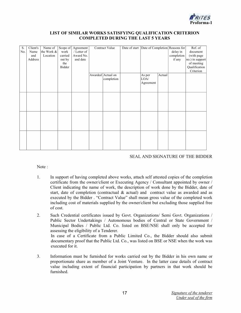
Proforma-1
LIST OF SIMILAR WORKS SATISFYING QUALIFICATION CRITERION
COMPLETED DURING THE LAST 5 YEARS
S.
No.
Client's
Name
and
Address
Name of
the Work &
Location
Scope of
work
carried
out by
the
Bidder
Agreement
/ Letter of
Award No.
and date
Contract Value Date of start Date of Completion Reasons for
delay in
completion
if any
Ref. of
document
(with page
no.) in support
of meeting
Qualification
Criterion
Awarded Actual on
completion
As per
LOA/
Agreement
Actual
SEAL AND SIGNATURE OF THE BIDDER
Note :
1. In support of having completed above works, attach self attested copies of the completion
certificate from the owner/client or Executing Agency / Consultant appointed by owner /
Client indicating the name of work, the description of work done by the Bidder, date of
start, date of completion (contractual & actual) and contract value as awarded and as
executed by the Bidder . “Contract Value” shall mean gross value of the completed work
including cost of materials supplied by the owner/client but excluding those supplied free
of cost.
2. Such Credential certificates issued by Govt. Organizations/ Semi Govt. Organizations /
Public Sector Undertakings / Autonomous bodies of Central or State Government /
Municipal Bodies / Public Ltd. Co. listed on BSE/NSE shall only be accepted for
assessing the eligibility of a Tenderer.
In case of a Certificate from a Public Limited Co., the Bidder should also submit
documentary proof that the Public Ltd. Co., was listed on BSE or NSE when the work was
executed for it.
3. Information must be furnished for works carried out by the Bidder in his own name or
proportionate share as member of a Joint Venture. In the latter case details of contract
value including extent of financial participation by partners in that work should be
furnished.

Signature of the tenderer
Under seal of the firm 18
4. If a Bidder has got a work executed through a Subcontractor on a back to back basis, the
Bidder cannot include such a work for his satisfying the Qualification Criterion even if
the Client has issued a Completion Certificate in favour of that Bidder.
5. Only similar works completed during the last 5 years prior to the last stipulated date for
submission of Bid, which meet the Qualification Criterion need be included in this list.

Signature of the tenderer
Under seal of the firm 19
Proforma 3
DECLARATION BY THE BIDDER
(Affidavit on Non-Judicial Stamp Paper of Rs.10/- duly attested by Notary / Magistrate)
This is to certify that We, M/s. __________________________, in submission of this offer
confirm that:-
i) We have not made any misleading or false representation in the forms, statements and
attachments in proof of the qualification requirements;
ii) We do not have records of poor performance such as abandoning the work, not properly
completing the contract, inordinate delays in completion, litigation history or financial
failures etc.
iii) No Central / State Government Department/ Public Sector Undertaking or Enterprise of
Central / State Government has banned/suspended business dealings with us as on date.
iv) We have submitted all the supporting documents and furnished the relevant details as per
prescribed format.
v) List of Similar Works satisfying Qualification Criterion indicated in Proforma 1 does not
include any work which has been carried out by us through a Subcontractor on a back to
back basis.
vi) The information and documents submitted with the Tender and those to be submitted
subsequently by way of clarifications / making good deficient documents are correct and
we are fully responsible for the correctness of the information and documents submitted
by us.
vii) We understand that in case any statement/information/document furnished by us or to be
furnished by us in connection with this offer, is found to be incorrect or false, our EMD in
full will be forfeited and business dealings will be banned.
SEAL, SIGNATURE & NAME OF THE BIDDER
signing this document
ANNEXURE I A

Signature of the tenderer
Under seal of the firm 20
CHECK LIST OF DOCUMENTS TO BE SUBMITTED
1. a) BY BIDDERS OTHER THAN JOINT VENTURES
i) Work Experience
- Similar Work Experience : Proforma 1 of Annexure I with details of 1, 2
or 3 works as the case may be, which satisfy requisite qualification
criterion with self attested copies of supporting document (Refer Para 2a of
Annexure I).
ii) Declaration by Bidder
Proforma 3 (Refer Para 6 of Annexure I)

Signature of the tenderer
Under seal of the firm 21
ANNEXURE II A
QUALIFICATION INFORMATION/CHECKLIST OF DOCUMENTS
--LETTER OF TRANSMITTAL BY OTHER THAN JOINT VENTURES
(on letter head of the Applicant)
From To
_____________ RITES Ltd._________
(Authority Inviting Tender)
Sir,
Sub: Submission of Qualification information /documents as per Checklist.
1. I/We hereby submit the following documents in support of my/our satisfying the
Qualification Criteria laid down for the work:-
a) Self attested copy of a certificate, confirming that the applicant is a working contractor
or has executed any work within the last five years reckoned from the date of opening
of Tender, issued by Railways, CPWD, MES, DOT, RITES, State PWD or any other
Central/State Government Undertaking, Municipal Body, Autonomous Body of
Central or State Government or Public Limited Company listed on NSE/BSE.
b) Work Experience
i) Similar Work Experience :- In Proforma 1 with details of 1 / 2 / 3 works as
applicable and self attested copies of supporting documents as mentioned therein.
2. In addition the following supporting documents are also enclosed.
a) Self attested copy of Partnership Deed/Memorandum and Articles of Association
of the Firm.
b) Self attested copies of PAN/TAN issued by the Income Tax Department.
c) Declaration – Proforma 3
d) Self attested copy of Sales Tax, Works Contract Tax, Service Tax Registration
Certificate (as applicable).
e) Self attested copy of Registration under Labour Laws, like PF, ESI etc.
f) Self attested copy of ISO 9000 Certificate ( if any)
2. I authorize you to approach any Bank, Individual, Employer, Firm or Corporation,
whether mentioned in the enclosed documents or not, to verify our competence and
general reputation.
3. I also enclose written Power of Attorney of the signatory of the Tender on behalf of the
Tenderer.
Yours faithfully,
Encl: As in Paras 1, 2 & 4
Signature of Applicant
with Name _________________
Date with seal
Signature of the tenderer
Under seal of the firm 22
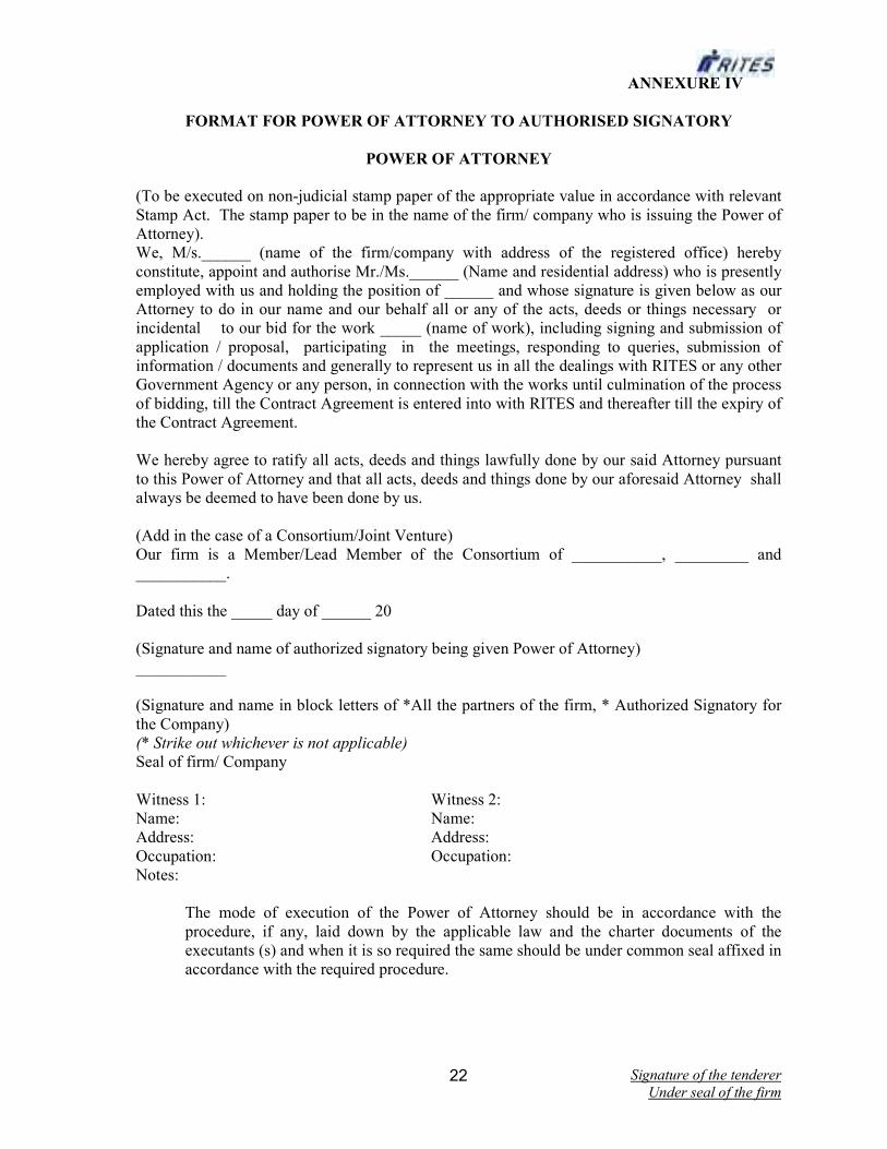
ANNEXURE IV
FORMAT FOR POWER OF ATTORNEY TO AUTHORISED SIGNATORY
POWER OF ATTORNEY
(To be executed on non-judicial stamp paper of the appropriate value in accordance with relevant
Stamp Act. The stamp paper to be in the name of the firm/ company who is issuing the Power of
Attorney).
We, M/s.______ (name of the firm/company with address of the registered office) hereby
constitute, appoint and authorise Mr./Ms.______ (Name and residential address) who is presently
employed with us and holding the position of ______ and whose signature is given below as our
Attorney to do in our name and our behalf all or any of the acts, deeds or things necessary or
incidental to our bid for the work _____ (name of work), including signing and submission of
application / proposal, participating in the meetings, responding to queries, submission of
information / documents and generally to represent us in all the dealings with RITES or any other
Government Agency or any person, in connection with the works until culmination of the process
of bidding, till the Contract Agreement is entered into with RITES and thereafter till the expiry of
the Contract Agreement.
We hereby agree to ratify all acts, deeds and things lawfully done by our said Attorney pursuant
to this Power of Attorney and that all acts, deeds and things done by our aforesaid Attorney shall
always be deemed to have been done by us.
(Add in the case of a Consortium/Joint Venture)
Our firm is a Member/Lead Member of the Consortium of ___________, _________ and
___________.
Dated this the _____ day of ______ 20
(Signature and name of authorized signatory being given Power of Attorney)
___________
(Signature and name in block letters of *All the partners of the firm, * Authorized Signatory for
the Company)
(* Strike out whichever is not applicable)
Seal of firm/ Company
Witness 1: Witness 2:
Name: Name:
Address: Address:
Occupation: Occupation:
Notes:
The mode of execution of the Power of Attorney should be in accordance with the
procedure, if any, laid down by the applicable law and the charter documents of the
executants (s) and when it is so required the same should be under common seal affixed in
accordance with the required procedure.

Signature of the tenderer
Under seal of the firm 23
ANNEXURE VI
(FORM OF LETTER OF ACCEPTANCE)
(By REGD POST / ACK.DUE)
(On the letter head of RITES)
NO. : RITES/ Dated :
To
_________________aggregate
(Name & Address of the Contractor)
Dear Sirs,
Sub: TENDER No. FOR THE WORK OF
Ref: Your Tender dated _________________ and letters dated _____________
and this office letter Nos. ___________ dated___________ in reply to the same.
This is to notify you that your Tender for the work under reference has been accepted by the
Competent Authority of RITES LIMITED for a total Contract Price of Rs. _______ (Rupees
_____________only) in its capacity as an Agent /Power of Attorney Holder acting for and on
behalf of ______ (the Employer).
Pursuant to Clause 1 of the Contract, you are required to furnish irrevocable Performance
Guarantee for an amount equivalent to 5% (Five percent) of the Contract Price and an Additional
Performance Guarantee for an amount of Rs. ------------ (if applicable). The Guarantee Bonds
aggregating for an amount of Rs.______________ are required to be submitted within ___ days
of issue of this Letter of Acceptance. Bank Guarantees issued by the following Banks will not be
acceptable _____________________ (Names of Banks _________)
The time of ________months allowed for execution of the work will be reckoned from the date of
start as defined in Schedule F or from the first day of the handing over of the site, whichever is
later, in accordance with phasing, if any, indicated in tender document.
You are requested to contact _________ (complete designation and address of the Project
Coordinator) for carrying out the contract.
You are also requested to attend this office within Twenty Eight days from the date of issue of
this letter for execution of the formal agreement. It may be noted that no payment shall be made
for any work carried out by you till the Agreement is executed and till such time the Performance
Guarantee and Additional Performance Guarantee (where applicable) has/have been submitted by
you.
This Letter of Acceptance is being sent to you in duplicate and you are requested to return without
delay one copy of the letter duly signed and stamped, as a token of your acknowledgement.
Signature of the tenderer
Under seal of the firm 24
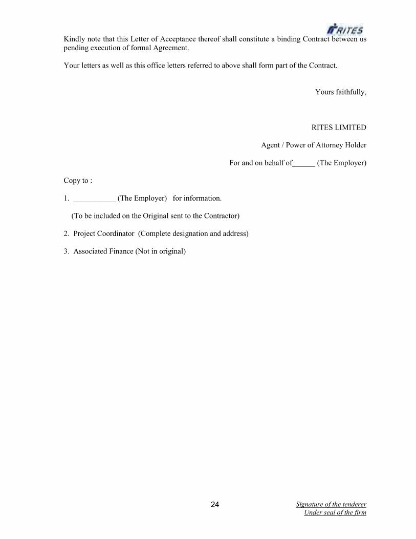
Kindly note that this Letter of Acceptance thereof shall constitute a binding Contract between us
pending execution of formal Agreement.
Your letters as well as this office letters referred to above shall form part of the Contract.
Yours faithfully,
RITES LIMITED
Agent / Power of Attorney Holder
For and on behalf of______ (The Employer)
Copy to :
1. ___________ (The Employer) for information.
(To be included on the Original sent to the Contractor)
2. Project Coordinator (Complete designation and address)
3. Associated Finance (Not in original)
Signature of the tenderer
Under seal of the firm 25
ANNEXURE VII
FORM OF AGREEMENT
(ON NON JUDICIAL STAMP PAPER OF APPROPRIATE VALUE)
Agreement No. ________ dated _________
THIS AGREEMENT is made on ________ day of ______ Two thousand ________ between
RITES Ltd. a Government of India Enterprise and a Company registered under Companies Act,
1956 having its registered office at SCOPE Minar, Laxmi Nagar, Delhi - 110092 and its
Corporate Office at RITES BHAWAN, Plot No.1, Sector 29, Gurgaon (Haryana) representing
through ____________, RITES LIMITED acting for and on behalf of and as an Agent /Power of
Attorney Holder of _____ hereinafter called the Employer (which expression shall, wherever the
context so demands or requires, include their successors in office and assigns) on one part and
M/s.______ hereinafter called the Contractor (which expression shall wherever the context so
demands or requires, include his/ their successors and assigns) of the other part.
WHEREAS the Employer is desirous that certain works should be executed viz.___________
(brief description of the work) and has by Letter of Acceptance dated ____ accepted a tender
submitted by the Contractor for the execution, completion, remedying of any defects therein and
maintenance of such works at a total Contract Price of Rs. ______ (Rupees ______________
only)
NOW THIS AGREEMENT WITNESSETH as follows:-
1. In this Agreement words and expressions shall have the same meaning as are respectively
assigned to them in the Conditions of Contract hereinafter referred to.
2. The following documents in conjunction with addenda/ corrigenda to Tender Documents
shall be deemed to form and be read and construed as part of this agreement viz.
The Letter of Acceptance dated______.
Priced Schedule (Bill) of Quantities
Notice Inviting Tender and Instructions to Tenderers.
RITES Tender and Contract Form
Special Conditions
Schedules A to F.
Technical Specifications
Drawings
Amendments to Tender Documents (List enclosed)
General Conditions of Contract (read with Correction Slip Nos. 1 to --) comprising of
(i) Conditions of Contract
(ii) Clauses of Contract
(iii) RITES Safety Code
(iv) RITES - Model Rules for the protection of Health and Sanitary
arrangements for Workers
(v) RITES – Contractor's Labour Regulations.
3. In consideration of the payment to be made by the Employer to the Contractor as
hereinafter mentioned, the Contractor hereby covenants with the Employer to execute,
complete, remedy defects therein and maintain the works in conformity in all respects
with the provisions of the Contract.
Signature of the tenderer
Under seal of the firm 26
4. The Employer hereby covenants to pay to the Contractor in consideration of the execution,
completion, remedying of any defects therein and maintenance of the works, the contract
price or such other sum as may become payable under the provisions of the contract at the
time and in the manner prescribed by the Contract.
IN WITNESS whereof the parties hereto have caused their respective common seals to be
hereinto affixed (or have herewith set their respective hands and seals) the day and year first
above written.
SIGNED, SEALED AND DELIVERED BY
____________________________
In the capacity of _____
On behalf of M/s. _________
(The Contractor)
In the presence of
Witnesses (Signature, Name &
Designation)
1.
2.
______________________________
representing RITES LIMITED
In the capacity of Agent / Power of
Attorney Holder
For and on behalf of _________
(The Employer)
In the presence of
Witnesses (Signature, Name &
Designation)
1.
2.

Signature of the tenderer
Under seal of the firm 27
ANNEX-A
Guidelines on Banning of Business Dealings
1. Introduction
1.1 RITES, being a Public Sector Enterprise and ‘State’, within the meaning of Article 12 of
Constitution of India, has to ensure preservation of rights enshrined in Chapter III of the
Constitution. RITES has also to safeguard its commercial interests. It is not in the interest
of RITES to deal with Agencies who commit deception, fraud or other misconduct in the
execution of contracts awarded / orders issued to them. In order to ensure compliance with
the constitutional mandate, it is incumbent on RITES to observe principles of natural
justice before banning the business dealings with any Agency.
1.2 Since banning of business dealings involves civil consequences for an Agency concerned,
it is incumbent that adequate opportunity of hearing is provided and the explanation, if
tendered, is considered before passing any order in this regard keeping in view the facts and
circumstances of the case.
2. Scope
2.1 The procedure of (i) Suspension and (ii) Banning of Business Dealing with Agencies, has
been laid down in these guidelines.
2.2 It is clarified that these guidelines do not deal with the decision of the Management not to
entertain any particular Agency due to its poor / inadequate performance or for any other
reason.
2.3 The banning shall be with prospective effect, i.e., future business dealings.
3. Definitions
In these Guidelines, unless the context otherwise requires:
i) `Bidder / Contractor / Supplier' in the context of these guidelines is indicated as
‘Agency’.
ii) ‘Competent Authority’ and ‘Appellate Authority’ shall mean the following:
a) The Director shall be the ‘Competent Authority’ for the purpose of these
guidelines. MD, RITES shall be the ‘Appellate Authority’ in respect of
such cases.
b) MD, RITES shall have overall power to take suo-moto action on any
information available or received by him and pass such order(s) as he may
think appropriate, including modifying the order(s) passed by any authority
under these guidelines.
iii) ‘Investigating Department’ shall mean any Department, Division or Unit
investigating into the conduct of the Agency and shall include the Vigilance
Department, Central Bureau of Investigation, the State Police or any other
Signature of the tenderer
Under seal of the firm 28
department set up by the Central or State Government having powers to
investigate.
4. Initiation of Banning / Suspension:
Action for banning / suspension business dealings with any Agency should be initiated by
the department/ unit having business dealings with them after noticing the irregularities or
misconduct on their part.
5. Suspension of Business Dealings
5.1 If the conduct of any Agency dealing with RITES is under investigation by any
department, the Competent Authority may consider whether the allegations under
investigation are of a serious nature and whether pending investigation, it would be
advisable to continue business dealing with the Agency. If the Competent Authority, after
consideration of the matter including the recommendation of the Investigating
Department/Unit, if any, decides that it would not be in the interest to continue business
dealings pending investigation, it may suspend business dealings with the Agency. The
order to this effect may indicate a brief of the charges under investigation. The order of
such suspension would operate for a period not more than six months and may be
communicated to the Agency as also to the Investigating Department.
The Investigating Department/Unit may ensure that their investigation is completed and
whole process of final order is over within such period.
5.2 As far as possible, the existing contract(s) with the Agency may be continued unless the
Competent Authority, having regard to the circumstances of the case, decides otherwise.
5.3 If the Agency concerned asks for detailed reasons of suspension, the Agency may be
informed that its conduct is under investigation. It is not necessary to enter into
correspondence or argument with the Agency at this stage.
5.4 It is not necessary to give any show-cause notice or personal hearing to the Agency before
issuing the order of suspension. However, if investigations are not complete in six months
time, the Competent Authority may extend the period of suspension by another three
months, during which period the investigations must be completed.
6. Grounds on which Banning of Business Dealings can be initiated
6.1 If the security consideration, including questions of loyalty of the Agency to the State, so
warrants;
6.2 If the Director / Owner of the Agency, proprietor or partner of the firm, is convicted by a
Court of Law for offences involving moral turpitude in relation to its business dealings
with the Government or any other public sector enterprises or RITES, during the last five
years;
6.3 If there is strong justification for believing that the Directors, Proprietors, Partners, owner
of the Agency have been guilty of malpractices such as bribery, corruption, fraud,
substitution of tenders, interpolations, etc;

Signature of the tenderer
Under seal of the firm 29
6.4 If the Agency employs a public servant dismissed / removed or employs a person
convicted for an offence involving corruption or abetment of such offence;
6.5 If business dealings with the Agency have been banned by the Govt. or any other public
sector enterprise;
6.6 If the Agency has resorted to Corrupt, fraudulent practices including
misrepresentation of facts;
6.7 If the Agency uses intimidation / threatening or brings undue outside pressure on the
Company (RITES) or its official in acceptance / performances of the job under the
contract;
6.8 If the Agency indulges in repeated and / or deliberate use of delay tactics in complying
with contractual stipulations;
6.9 Based on the findings of the investigation report of CBI / Police against the Agency for
malafide / unlawful acts or improper conduct on his part in matters relating to the
Company (RITES) or even otherwise;
6.10 Established litigant nature of the Agency to derive undue benefit;
6.11 Continued poor performance of the Agency in several contracts;
(Note: The examples given above are only illustrative and not exhaustive. The Competent
Authority may decide to ban business dealing for any good and sufficient reason).
7. Banning of Business Dealings
7.1 A decision to ban business dealings with any Agency shall apply throughout the
Company.
7.2 If the Competent Authority is prima-facie of view that action for banning business
dealings with the Agency is called for, a show-cause notice may be issued to the Agency
as per paragraph 8.1 and an enquiry held accordingly.
8. Show-cause Notice
8.1 In case where the Competent Authority decides that action against an Agency is called for,
a show-cause notice has to be issued to the Agency. Statement containing the imputation
of misconduct or mis-behaviour may be appended to the show-cause notice and the
Agency should be asked to submit within 30 days a written statement in its defence. If no
reply is received, the decision may be taken ex-parte.
8.2 If the Agency requests for inspection of any relevant document in possession of RITES,
necessary facility for inspection of documents may be provided.
8.3 After considering the reply of the Agency and other circumstances and facts of the case, a
final decision for Company-wide banning shall be taken by the Competent Authority. The
Competent Authority may consider and pass an appropriate speaking order:
a) For exonerating the Agency if the charges are not established;
Signature of the tenderer
Under seal of the firm 30
b) For banning the business dealing with the Agency.
8.4 The decision should be communicated to the Agency concerned along with a reasoned
order. If it decided to ban business dealings, the period for which the ban would be operative
may be mentioned.
9. Appeal against the Decision of the Competent Authority
9.1 The Agency may file an appeal against the order of the Competent Authority banning
business dealing, etc. The appeal shall lie to Appellate Authority. Such an appeal shall be
preferred within one month from the date of receipt of the order banning business dealing,
etc.
9.2 Appellate Authority would consider the appeal and pass appropriate order which shall be
communicated to the Agency as well as the Competent Authority.
10. Review of the Decision by the Competent Authority
Any petition / application filed by the Agency concerning the review of the banning order
passed originally by Competent Authority under the existing guidelines either before or
after filing of appeal before the Appellate Authority or after disposal of appeal by the
Appellate Authority, the review petition can be decided by the Competent Authority upon
disclosure of new facts /circumstances or subsequent development necessitating such
review.
11. Circulation of the names of Agencies with whom Business Dealings have been
banned.
11.1 Depending upon the gravity of misconduct established, the Competent Authority of
RITES may circulate the names of Agency with whom business dealings have been
banned, to the Ministry of Railways and PSUs of Railways, for such action as they deem
appropriate.
11.2 If Ministry of Railways or a Public Sector Undertaking of Railways request for more
information about the Agency with whom business dealings have been banned a copy of
the report of Inquiring Authority together with a copy of the order of the Competent
Authority/ Appellate Authority may be supplied.
12. Restoration
12.1 The validity of the banning order shall be for a specific time & on expiry of the same, the
banning order shall be considered as "withdrawn".
12.2 In case any agency applies for restoration of business prior to the expiry of the ban order,
depending upon merits of each case, the Competent Authority which had passed the
original banning orders may consider revocation of order of suspension of business/lifting
the ban on business dealings at an appropriate time. Copies of the restoration orders shall
be sent to all those offices where copies of Ban Orders had been sent.

Signature of the tenderer
Under seal of the firm 31
PART-1
SECTION 2
TENDER AND CONTRACT FOR WORKS
Signature of the tenderer
Under seal of the firm 32
SECTION 2
TENDER AND CONTRACT FORM FOR WORKS
To
__________________________
Tender Accepting Authority/RITES
[Refer Schedule F (Conditions of Contract)]
Name, Designation / Address
Sub: TENDER FOR THE WORK OF ___________ ______________
(TENDER No. ______________________ ISSUED BY ____________)
TENDER
1. I/We have read and examined the Notice Inviting Tender and Instructions to Tenderers,
Special Conditions, Schedules A to F, Technical Specifications, Drawings, Schedule /
Bill of Quantities and General Conditions of Contract as well as other documents and
rules referred to in GCC and all the details contained in the Tender Document for the
work.
2. I/We hereby tender for the execution and completion of the work and remedy any defects
therein, specified in the Schedule of Quantities within the time specified in Schedule “F”,
and in accordance in all respects with the specifications, designs, drawings and
instructions in writing referred to in Notice Inviting Tender and Instructions to Tenderers
and in Clause 11 of the Clauses of Contract and with such materials as are provided for,
by, and in respects in accordance with, such conditions so far as applicable.
3. We agree that our tender shall remain valid for a period of 90 days from the due date for
submission of bid or extended date as stipulated and not to make any modifications in its
terms and conditions.
4. A sum of Rs. ___________ (Rupees _________ only) is hereby forwarded in the form of
Banker’s cheque/Pay Order /Demand Draft issued in favour of RITES Ltd., payable at
_________ as the Earnest Money.
5. If I/We withdraw my/our tender during the period of tender validity or before issue of
Letter of Acceptance which ever is earlier or make modifications in the Terms and
Conditions of the Tender which are not acceptable to the Employer, then the Employer
shall, without prejudice to any other right or remedy, be at liberty to forfeit entire Earnest
Money absolutely.
6. If I/We fail to furnish the prescribed Performance Guarantee and Additional Performance
Guarantee (if applicable) within prescribed period, I/We agree that the said Employer
shall, without prejudice to any other right or remedy, be at liberty to forfeit the said
Earnest Money absolutely.
7. If, I/We fail to commence the work within the specified period, I/We agree that the
Employer shall, without prejudice to any other right or remedy available in law, be at
liberty to forfeit the Earnest Money and Performance Guarantee and Additional
Performance Guarantee (if applicable) absolutely.
Signature of the tenderer
Under seal of the firm 33
8. Further, I/We hereby agree that in case of forfeiture of Earnest Money or both Earnest
Money & Performance Guarantee and Additional Performance Guarantee (if applicable)
as aforesaid in paras 5 to 7, I/We shall be debarred from participation in re-tendering
process of the work.
9. On issue of Letter of Acceptance by the Employer, I/We agree that the said Earnest
Money shall be retained by the Employer towards Security Deposit, to execute all the
works referred to in the Tender document upon the Terms and Conditions contained or
referred to therein and to carry out such deviations as may be ordered, upto maximum of
the percentage mentioned in Schedule F at rates as stipulated in relevant Clauses of
contract and those in excess of that limit at the rates to be determined in accordance with
the provisions contained in Clauses 12.2 and 12.3 of the tender form.
10. I/We hereby agree that I/ We shall sign the Formal Agreement with the Employer within
28 days from the date of issue of Letter of Acceptance. In case of any delay, I/We agree
that we shall not submit any Bill for Payment till the Contract Agreement is signed.
11. I/We hereby declare that I/We shall treat the tender documents, drawings and other
records connected with the work as secret/confidential documents and shall not
communicate information derived there from to any person other than a person to whom
I/We am/are authorized to communicate the same or use the information in any manner
prejudicial to the safety of the Employer/State.
12. I/We hereby declare that I/We have not laid down any condition/deviation to any content
of Technical Bid and/or Financial Bid. I/We agree that in case any condition is found to
be quoted by us in the Technical and/or Financial Bid, my/our Tender may be rejected.
13. I/We understand that the Employer is not bound to accept the lowest or any tender he may
receive. I/We also understand that the Employer reserves the right to accept the whole or
any part of the tender and I/We shall be bound to perform the same at the rates quoted.
14. Until a formal agreement is prepared and executed, this bid together with our written
acceptance thereof shall constitute a binding contract between us and RITES.
15. I am/We are signing this Tender offer in my / our capacity as one/those authorized to sign
on behalf of my/our company/as one holding the Power of Attorney issued in my favour
as Lead Member by the Members of the Joint Venture.
Signature of Authorized Person/s
Date
Name/s & Title of Signatory
Name of Tenderer
Postal Address
Seal
Witness
Signature
Name
Postal Address
Occupation

Signature of the tenderer
Under seal of the firm 34
PART-1
SECTION – 3
SPECIAL CONDITIONS OF CONTRACT
Signature of the tenderer
Under seal of the firm 35
SECTION 3
SPECIAL CONDITIONS
Special Conditions relating to existing Clauses of Contract: 1) The salient terms and conditions besides the General conditions of contract and Instruction to
Tenderers are given below: -
2) Tender(s) should quote his/their rates on percentage rate basis neatly in figure as well as in words.
Tenders containing erasures and alternation of the tender documents are liable to be rejected. Any
correction made by the Tenderer(s) in his/their entries must be attested by him/them, failing which
the Tender is liable to be rejected at the discretion of RITES Ltd.
3) The quoted rates should be inclusive of Inspection Charges and all taxes and duties of Central,
State, Local bodies including Loading, transportation, unloading and stacking at site store,. The
quoted rate shall remain firm during the currency of the Contract.
4) Period of Maintenance/Defect Liability period: As per clauses of contract in GCC applicable to
this work-12 months from date of completion
5) The Contractor has to work along with other agencies in and around the area allotted for his works.
He should execute all his works in complete co-ordination and co-operation with all such agencies
and provide access to other agencies so that at no time either his work or the work of other
agencies is stopped or delayed. In case of any dispute in this regard, the decision of Engineer-in-
charge or his representative will be final and binding on the Contractor. No claim for idle labour,
plant and machinery under any circumstances will be entertained by the RITES.
6) SERVICE ROAD: - Contractor will provide service road/roads for movement of materials as per
direction of Engineer-in-charge. Contractor will also maintain these service roads in safe and fit
condition at his own cost. He will however have no authority to prevent use of such roads by
Employer/RITES and other bonafide contractors working at site. Employer/RITES will, however,
have the authority to disallow any movement on the road, which in their opinion is not in the
interest of work. If the contractor fails to provide service road to the satisfaction of the Engineer-in-charge it will be provided by the Engineer-in-charge at Contractor’s cost. However in case any
such road is not required for the purpose of the work, nothing shall be deducted from contractor’s
payments on this account.
7) The contractor shall, after completion of work, clear the site of all debris and left over materials, at
his own expense to the entire satisfaction of Engineer In charge.
8) Contractor should be registered with the concerned department of Employees Provident Fund
Organisation (EPFO). No payment shall be released to the contractor until and unless the
contractor submits the registration certificate and upto date deposit receipt of provident
fund due to be deposited by him.
9) At the time of submission of RA/Final bill a certificate shall be submitted by the contractor
regarding upto date clearance of payment to his/their sub contractors, vendors, suppliers, labour
contractor etc. if any
10) The Schedule of items of work to be carried out, provided in the SCHEDULE OF QUANTITIES”
gives only brief description of each of the items. Execution of these items will be governed by the
Technical specifications. For detailed specifications reference may be made to Section 5
“Technical Specifications” in general and in particular to the various Guidelines and Specifications listed in Para 1.0 “Preamble to Technical Specification” of Section 5. RITES'
representative at site will be fully empowered to provide guidance in the matter of execution of the
works and his instructions will be final and binding in this regard.
Signature of the tenderer
Under seal of the firm 36
11) The Contractor will bear all medical expenses and make immediate arrangement for medical
attention to his labourer, if inhered on duty. He will provide “Medical Aid” Box at site at his cost.
12) No material, equipment or machinery will be supplied by RITES/Client. You have to arrange all
labour, materials or machinery for loading, transportation, unloading and stacking at site at your
own cost.
13) On submission of bills to Site-In-Charge, RITES at site office, it will be recorded in RITES
Measurement Book at site which are to be countersigned by a person of suppliers having Power of
Attorney to sign the bills & M.Bs.
14) No payment will be made unless copy of the current & valid S.T.C.C. or exemption certification
are submitted prior to or along with the bills and no payment will be made without obtaining
insurance policies for the work such as Contractor’s all risk policy, workmen compensation policy,
plant & equipment policy etc.
15) Contractor shall submit to RITES the entry challan of incoming materials like cememt,rod,brick
etc. for verification of Stores and record.
16) Contractor should maintain the daily cement consumption & steel consumption register. Engineer
- in - charge or his representative may check the registers and the challans at any time.
17) NIGHT WORK:- The contractor would be required to carry out the work even at night, without
conferring any right on the contractor for claiming for extra payment for introducing night
working. The decision of the Engineer-in-charge in this regard will be final and binding on the
contractor. Contractor shall make his own arrangement for sufficient illumination at site. Nothing
extra will be paid for doing works at night.
18) FIRST AID:-The contractor shall maintain in a readily accessible place first aid appliance including an adequate supply of sterilized dressing and sterilized cotton wool. The appliances shall
be placed under the charge of responsible person who shall be readily available during working
hours.
19) The contractor shall also provide, fix & be responsible for the maintenance of all stakes, templates
profiles, levels marks, points etc. and must take all necessary precautions to prevent these being
removed altered or disturbed and will be held responsible for the consequences of such removal, alteration or disturbances should the same take place and for their efficient reinstatement.
20) HANDING OVER OF SITE :-Efforts will be made by the Employer to hand over the site to the
Contractor free of encumbrance. However, in case of any delay in handing over of the site to the
Contractor, the Employer shall only consider suitable extension of time for the execution of the
work. It should be clearly understood that the Employer shall not consider any other
compensation whatsoever viz. towards idleness of contractor’s labour equipment etc.
21) The Employer reserves the right to hand over the site in parts progressively to the Contractor. The
Contractor will be required to do the work on such released-fronts in parts without any reservation
whatsoever.
22) The access roads near, to the work site may not be available at the time of Mobilisation by the
Contractor. The Contractor shall plan his work within the plant area as per available roads at site.
All drainage of works area and all other weather truckable/haulage roads as required by the
Contractor shall be constructed and maintained during the construction period by the Contractor at
his own cost.

Signature of the tenderer
Under seal of the firm 37
23) Completion Drawing: Completion drawings for the works executed shall be prepared by the
contractor at his cost on tracing paper. The contractor will supply five copies of ammonia print of
completion drawing duly signed along with original tracing plan with the final bill.
26) The work will be executed as per rule of local authority.
27) No water point & electric point will be provided by RITES
28) Site office & labour camp are to be constructed as per prevalent norms
29) Labour , working staff to be engaged for the work are to be guided by prevalent rule.
30) No extra payment will be made for any dewatering/bailing out water from excavation-pit.
Signature of the tenderer
Under seal of the firm 38
PART-1
SECTION 4
SCHEDULE – A TO F

Signature of the tenderer
Under seal of the firm 39
SECTION 4
PROFORMA OF SCHEDULES
(Operative Schedules to be supplied separately to each intending Tenderer)
SCHEDULE ‘A’
Schedule of quantities ( As per Bill of Quantities attached)
(BOQ to be attached with Financial Bid)
SCHEDULE ‘B’ –
Schedule of materials to be issued to the contractor. (Refer Clause 10 of Clauses of Contract)
S.No Description of
items
Quantity Rates in Figures & words at
which the material will be
charged to the contractor
Place of Issue
1 2 3 4 5
- Not Applicable -
SCHEDULE ‘C’ –
Tools and plants to be hired to the contractor. (Refer clause 34 of Clauses of Contract).
S.No Description Hire charges per day Place of Issue
1 2 3 4
- Not Applicable -
SCHEDULE ‘D’
Extra schedule for specific requirements/documents for the work, if any.
- Not Applicable -
Signature of the tenderer
Under seal of the firm 40
SCHEDULE ‘E’ –
Schedule of components of Cement, Steel, other materials, POL,
Labour etc .for price escalation. (Refer Clause 10CC of Clauses
of Contract).
(To be worked out and filled by NIT approving authority. The
Components and their percentages may be modified depending on
the nature of work)
CLAUSE 10 CC
Component of Cement (Xc)
expressed as percent of total value of work _______%
Component of steel (X5)
expressed as percent of total value of work ______%
Component of other materials (XM) (except cement & steel)
expressed as per cent of total value of work ______%
Component of labour (Y)
expressed as percent of total value of work _______%
Component of P.O.L (Z)
expressed as percent of total value of work _______%
______________
Total 100 %_
SCHEDULE ‘F’
Reference to General Conditions of Contract
Name of Work :Construction of RPF Office,GRP Barrack & other establishments at Bolpur,Dt-
Birbhum,WB
Estimated cost of work Rs. 76,26,092.40
Earnest money : Rs. 76,300/-
Performance Guarantee (Ref. Clause 1) 5% of Tendered value.
Security Deposit: (Refer clause 1A) 5% of Tendered value
Notice Inviting Tender and Instruction to Tenderers
Officer inviting tender : : Office of the General Manager(P);2nd floor-Metro Railway Service
Building;56-C.R.Avenue;Kolkata-700012
Signature of the tenderer
Under seal of the firm 41
CONDITIONS OF CONTRACT
Definitions
2 (iv) Employer E.Rly
2(v) Engineer-in-Charge General Manager(P)/RITES Ltd
(Authority competent to execute Contract
Agreement as per Item 7.2 of SOP)
2(vii) Accepting Authority General Manager(P)/RITES Ltd
(Authority competent to accept Tenders as per
Item 3.1/3.2/ 3.3 of SOP as applicable)
2(ix) Percentage on cost of materials
and labour to cover all 15%
overheads and profits.
2(x) Standard Schedule of Rates E.Rly Unified SOR-2011 (to be modified as per
requirement and as applicable)
2(xiii) Date of commencement of work 15 days from the date of issue of LOA or the first
date of handing over of site whichever is later
9 (a) (ii) General Conditions of Contract RITES General Conditions of Contract
2011 Edition as modified & corrected upto
C.S.No. _______________ dated -------
CLAUSES OF CONTRACT
Clause 1
1 (i) Time allowed for submission of
P.G. from the date of issue of
Letter of Acceptance subject 15 days.
to maximum of 15 days
Maximum allowable extension
beyond the period provided in
(i) above subject to a maximum of 7 days.
7 days
Clause 2
Authority for fixing compensation under
Clause 2 General Manager(P)
(Authority competent to accept Tender)
Clause 2A
Whether Clause 2A shall be applicable NO

Signature of the tenderer
Under seal of the firm 42
Clause 5
5.1 (a) Time allowed for execution of work 04 (four) months from the date of start
Date of start 15 days from the date of issue of
Letter of Acceptance or the first date
of handing over of site whichever is
later
5.1 (b) TABLE OF MILESTONE(S) :NIL
S.No Description of Milestone
(Physical)
Time allowed in days
(from date of start)
Amount to be withheld in
case of non achievement
of milestone
1
2
3
4
Clause 6 A Whether Clause 6 or 6A applicable 6
Clause 7
Gross work to be done together with net
payment/adjustment of advances for
material collected, if any, since the last such Rs 19 lakh
payment for being eligible to interim payment
Clause 10A
i) Whether Material Testing Laboratory is to
be provided at site. YES
ii) If “YES” list of equipments to be provided As per IS code
Clause 10 B
Whether Clause 10 B(ii) to (v) applicable NO
Clause 10 CC
Whether Clause 10CC applicable NO
Clause 11
Specifications to be followed for execution
of work CIVIL WORKS
E.Rly Unified Schedule-2011/IS code
.
ELECTRICAL WORKS
CPWD General Specifications
Part I Internal 2005
Part II External 1994

Signature of the tenderer
Under seal of the firm 43
Part III Lifts & Escalators 2003
Part IV Substations 2007
Part V Wet Riser
Sprinkler System 2006
Part VI Heating, Ventilation &
Air Conditioning Works 2005
Part VII DG Sets 2006
Clause 12
Clause 12.2 Deviation Limit beyond which i) For Non-foundation items.
12.3 & 12.5 Clauses 12.2,12.3 & 12.5shall Plus 25%
apply Minus No limit
ii) For Foundation Items
Plus 100%
Minus No limit
Note: For Earthwork, individual classi-
fication quantity can vary to any extent
but overall Deviation Limits will be as
above.
12.5 Definition of Foundation item if
other than that described in
Clause 12.5 No
Clause 16 Competent Authority for
deciding reduced rates General Manager(RITES)
(Authority Competent to accept Tender)
Clause 18 List of mandatory machinery, tools & plants to be deployed by the Contractor at
site:-
As per IS code
Clause 25
25 (i) Appellate Authority - ED/RITES
(The Authority immediately above
Engineer-in-charge to whom the
Engineer-in-charge report)
ED/RITES
Appointing Authority - (The Authority competent to appoint
Arbitrator as per Item 9.2 of SOP)
Clause 36 (i) & (iii)
Minimum Qualifications & Experience required and Discipline to which should belong
Designation Minimum
Qualification
Minimum
working
experience
Discipline to
which should
belong
Number
Principal Technical
Representative
Degree 05 yrs Civil Engg 1
Deputy Technical
Representative
Diploma 02 yrs Electrical
Engg
1

Signature of the tenderer
Under seal of the firm 44
36 (iv) Recovery for non-deployment of Principal Technical Representative and Deputy
Technical Representative
Designation Rate of Recovery per month (in Rs.) for non-
deployment
Principal Technical
Representative
30000/-
Deputy Technical Representative 15000/-
Clause 42
i)(a) Schedule/statement for determining Eastern Rly Unified SOR-2011
theoretical quantity of cement &
bitumen on the basis of Delhi
Schedule of Rates printed by CPWD
ii) Variations permissible on theoretical
quantities
a) Cement
- for works with estimated cost 3% plus / minus
put to tender not more than Rs.5 lakhs
- for works with estimated cost put to 2% plus / minus
tender more than Rs.5 lakhs
b) Bitumen for All Works 2.5% plus only & nil on minus side
c) Steel Reinforcement and structural 2% plus / minus
steel sections for each diameter,
section and category
d) All other materials Nil
RECOVERY RATES FOR QUANTITIES BEYOND PERMISSIBLE VARIATION
Sl.
No.
Description of
Item
Rates in figures and words at which recovery shall be made
from the Contractor
Excess beyond permissible
variation
Less use beyond the
permissible variation
1 Cement
2 Steel
reinforcement
3 Structural Sections
4 Bitumen issued
free
5 Bitumen issued at
stipulated fixed
price

Signature of the tenderer
Under seal of the firm 45
Clause 46
Clause 46.10
Details of temporary accommodation
including number of rooms and their
sizes as well as furniture to be made
available by the Contractor NIL
Whether Clause 46.11.1A applicable NO
Whether Clause 46.13A applicable NO
Clause 46.17
City of Jurisdiction of Court Kolkata
Clause 47.2.1
Sum for which Third Party Rs. 01 lakh Lakhs per occurrence
Insurance to be obtained. with the number of occurrences limited to four.
Clause 55
Whether clause 55 shall NO
be applicable.
If yes, time allowed for completion -
of sample floor/unit.
Signature of the tenderer
Under seal of the firm 46
Section - 5
TECHNICAL SPECIFICATIONS
Signature of the tenderer
Under seal of the firm 47
SECTION 5
TECHNICAL SPECIFICATIONS
1.0 STANDARD SPECIFICATIONS ISSUED BY CPWD
1.1 Civil Engineering Works
CPWD Specification 2009 Vol. I & II. These Specifications have replaced CPWD
Specifications 1996 along with Correction Slips issued on them. These Specifications
cover all types of Building Works. The specifications are available as a printed document
issued by CPWD and also in soft copy PDF Format in CPWD website.
1.2 Electrical Engineering Works
Part No. Description Year of issue
I Internal 2005
II External 1994
III Lifts and Escalators 2003
IV Sub Stations 2007
V Wet Riser and Sprinkler Systems 2006
VI Heating, Ventilations & Air
Conditioning Works 2005
VII D.G.Sets 2006
The above documents are available as Priced Document issued by CPWD and in soft copy
PDF Format in CPWD website.
2.0 STANDARD SPECIFICATIONS ISSUED BY MINISTRY OF SURFACE
TRANSPORT
Specifications for Road and Bridge works (Fourth Revision) August 2001 have been
published by Indian Road Congress as a priced document. These Specification cover
exhaustively various Road and Bridge works.
3.0 STANDARD SPECIFICATIONS ISSUED BY INDIAN RAILWAYS
Railway Board vide their letter No. 2009/LMD/01/03 dated 14/01/2010 have advised that
they have approved issue of “Indian Railways Unified Standard Specifications or
Materials and works with corresponding Indian Railways Unified Standard Schedule of
items (for rates of Materials and works)”. These documents are to be published by
Northern Railway on behalf of Railway Board after the Zonal Railways have made out
“Schedule of Rates” as applicable to them based on “Standard Analysis of Rates of items”.
These Specification however cover only Building and Road works generally on the lines
of CPWD and Ministry of Surface Transport. They do not cover Track works which are
governed by Manuals and RDSO/Indian Railway Specifications. Pending publication of
Signature of the tenderer
Under seal of the firm 48
Unified Standard Specifications, the specifications issued by the zonal Railways will be
applicable.
4.0 SPECIAL SPECIFICATIONS :
4.1 Work is to be carried out as per drawing
5. DISTRIBUTION BOARDS.
5.1. GENERAL:
5.1.1 Distribution boards for power and light circuit distribution shall be factory built and shall
be suitable for 415 volts, 3 phase or 230 volts single phase supply as specified in BOQ.
The distribution boards shall conform to IS 8623 (for factory built assembles)
5.2 TYPE:
5.2.1 Distribution Board shall be double door type suitable for flush installation. The boards
shall be of cabinet design, totally enclosed and shall provide protection against ingress to
IP 42/ IP43 of IS 2147. However, if none of the types available from the approved makes
meets the above requirement, alternative makes can be offered with technical literature
and copy of test certificate with the approval of the Engineer-in-charge.
5.3. COMPONENTS:
5.3.1 Distribution boards shall generally be provided with the following major components:
a. Miniature circuit breakers
b. Residual current circuit breaker.
c. Insulated Bus Bars
d. Neutral links/bus
d. Earth Bus
e. Loose Wire Box
5.3.2 Distribution board shall be provided with MCB and or Residual current circuit breaker as
mentioned in drawings and BOQ. Residual current (earth leakage) circuit breaker shall be
current operated type and of 30mA sensitivity unless otherwise stated. RCCB shall be
mounted within distribution board box. Distribution board box, MCBs, RCCBs used shall
be of one same manufacturer/make. Standard size DB manufactured by approved
manufacturer shall be used. In case size specified in BOQ is not standard size of
manufacturer, in that case next higher standard size distribution board box shall be used
with incoming & outgoing MCB as specified in BOQ. Additional cutout/space for
outgoing MCB shall be plugged with blank plates. No extra cost shall be paid for using
bigger/higher size distribution board box and blank plates.
5.4. MINIATURE CIRCUIT BREAKERS:
5.4.1 Miniature Circuit Breakers for lighting circuits shall be of “B” curve. Where as the circuits
feeding discharge lamps (HPMV / MH / HPSV) halogen lamps, all power outlet points,
equipment/machinery shall be of “C” Curve (Motor circuit) types. All miniature circuit
breakers shall be of 10 KA rated rupturing capacity unless otherwise stated. MCBs shall
generally conform to IS 8828. The miniature circuit breakers shall be suitable for snap
fixing on a standard DIN rail. The MCBs shall be suitable for operating under full load
under ambient temperature condition (i.e. 10 Dg C to 55 Dg C in India).
5.4.1 MCBs shall have terminals suitable for receiving Aluminium cables of adequate cross-
section (upto 32 Amp rating 16 sq mm and for 40, 50, 63 Ampere rating 35 sqmm cable).
Three phase MCBs shall have common trip bar so that all the poles make and break

Signature of the tenderer
Under seal of the firm 49
simultaneously. Miniature circuit breakers shall be quick make & quick break type with
trip free mechanism. MCB shall have thermal & magnetic short circuit protection.
5.5 RESIDUAL CURRENT CIRCUIT BREAKERS:
5.5.1 Residual current leakage circuit breakers shall be used as incomers in distribution boards
only wherever specially called for in BOQ, RCCB shall be suitable for incorporation in
standard DB manufactured by the approved manufactures. RCCB shall be of core balance
type and shall not cause nuisance tripping the RCCB shall be rated for 30mA fault circuit
tripping. RCCB shall be provided with test push button to test the healthiness of the
circuit.
5.6. BUS BARS
5.6.1 The bus bars shall be flameproof insulated copper and duly tinned or plated. The bus
bar rating shall be at least 100 amperes.
5.6.1.1 Three phase DBs shall have single piece bus bar and coupling link avoiding drilling
and bolting of bus bars.
5.6.1.2 However, if the above `unique bus bars' system is not available from the approved
manufacturers alternative makes can be offered with full technical particulars.
5.6.1.3 Neutral busbars shall be provided with the same number of terminals as there are single
ways on the board, in addition to the terminals for incoming mains. An earth bar of similar
size as the neutral bar shall also be provided. Phase barrier shall be fitted and all live parts
shall be screened from the front.
5.7. CABINET
5.7.1 The DB cabinet shall be made of at least 1.6mm thick sheet steel duly stove enameled or
powder coated (as per standards manufacturing product). The cabinet shall be suitable for
either recess mounting or surface mounting. The cabinet shall be provided with conduit /
cable entry knockouts at top and bottom or plates shall be of detachable construction. The
cabinet shall be dust and vermin proof with proper gaskets for the front door.
5.7.2 The DB cabinet and internal mounting arrangement shall be such that the entire bus and
MCB assembly can be easily detachable from the cabinet.
5.7.3 Distribution Board shall be double door type and suitable for flush installation. All
distribution boards shall be of three phase (415 Volts), [Three row 24/30/42 Module, 4
Pole modular I/C] or single phase (240 volts) [One row 8/10/14 Module] type with
incoming MCB and/or RCCB as in Schedule of quantities. Three phase DBs shall have
4Pole MCB as incommer (this MCB shall not be accommodated in the three rows) and
each row shall have one 2PoleRCCBand balance MCBs or Blanking plates. e.g. A 3 row,
24 module DB shall have 1 No. 4Pole MCB as incommer, 3 No. 2Pole RCCB / ELCBs
(one for each phase) and 18 No. SP MCBs or Blanking Plates. (Six for each
phase).Similarly a Single Phase DB shall have a 2Pole MCB as incomer and
2PoleRCCBand balance MCBs or Blanking plates.
5.7.4 Ample clearance shall be provided between all live metal and the earth case and adequate
space for all incoming and outgoing cables. All distribution board enclosures shall have an
etched zinc base stove painted followed by synthetic stove enameling, colour light grey.
Signature of the tenderer
Under seal of the firm 50
5.8. DIRECTORY
5.8.1 Distribution boards shall be provided with a write and protect directory indicating the
area of loads served by each circuit breakers, the rating of breakers, size of conductors etc.
The directory shall be in front of the cabinet. DAP Lines, Dwarka, N.Delhi Elect. Specs-
37 ES Elecserve Consultants Pvt Ltd.
5.9. INSTALLATION:
5.9.1 Distribution boards shall be surface mounted or recessed mounted as required. DBs shall
be mounted at the locations as shown on the approved execution drawings.
5.9.2 Surface boards shall be fixed with suitable angle iron clamps and bolts. All the
cables/conduits shall be properly terminated using glands/ check nuts etc. Wiring shall be
properly terminated using crimping lugs/ sockets and PVC identification ferrules.
Distribution boards shall be bonded to the earth at least at two points using brass bolts and
lugs. Suitable name plate and danger plate, indicating the voltage shall be fixed to the
front cover.
5.10. TESTING:
5.10.1 Distribution boards shall be tested at factory as per I.S. 8623 and original test certificate
shall be furnished.
The Contractor shall submit a write up of the Operation of the panel and get it
approved by the owner / Engineer-in-charge before fabrication of the panel
MEDIUM VOLTAGE DISTRIBUTION SYSTEM
(Internal Lighting & Power wiring)
1.0 GENERAL:
1.1 Medium voltage distribution system shall be applicable for wiring 3 phase, 4 wire 415
volts. 50 Hz, AC supply and single phase, 2 wire 230 volts, 50 Hz, AC supply.
1.2 This section covers the general technical requirements & measurement of the various
components in internal electrical installation works.
2.0. REGULATION & STANDARDS:
2.1 The system shall be governed by the requirements of IS: 732 and I.E. Rules and NEC. IS
Standards and Codes applicable for medium voltage distribution is also listed in
specification.
2.2 The definitions of terms shall be in accordance with IS: 732-1989 (Indian Standard Code
of Practice for Electrical Wiring), except for the definitions of point, circuit, & sub-main
wiring, which are defined in clauses hereunder.
2.3 The conventional signs & symbols for technical work shall be as shown in drawing.
3.0 POINT WIRING
3.1 A point (other than socket outlet point) shall include all work necessary in complete
wiring to the following outlets from the controlling switch or MCB. The scope of wiring

Signature of the tenderer
Under seal of the firm 51
for a point shall however, includes the wiring work necessary in tapping from another
point in the same distribution circuit.
a) Ceiling rose or connector ( in the case of points for ceiling / exhaust fan points,
prewired light and call bells)
b) Ceiling rose (in case of pendants except stiff pendants).
c) Back plate (in case of stiff pendants.)
d) Lamp holder (in case of goose neck type wall brackets, batten holders and fittings
which are not pre-wired).
Note: In case of call bell points, the words “controlling switch or MCB” shall be read as
“from the ceiling rose meant for connection to bell push”.
3.2 Following shall be deemed to be included in point wiring.
a) Conduit, conduit accessories for the same and wiring cables between the switch box and
the point outlet. See also (g) below.
b) All fixing accessories such as clips, nails, screws, Phil plug etc. as required.
c) Metal switch boxes for control switches, regulators, sockets etc. recessed or surface
type, and
i) Phenolic laminated sheet covers over the same for piano type switches.
ii) Screw less modular plates cover the same for modular type switches and MCBs.
d) Outlet boxes, junction boxes, pull through boxes etc. but excluding metal boxes if any,
provided with switch boards for loose wires / conduit terminations.
e) Control switch piano type , modular type , MCB as specified in the BOQ f) Three pin or
six pin socket, ceiling rose or connector as required (2 pin & 5 pin socket outlet shall not
be permitted).
g) Connections to ceiling rose, connector, socket outlet, lamp holder, switch etc.
h) Interconnecting wiring between points in the same circuit, in the same switch box or
from another switch box.
i) Protective ( loop earthing) conductor from one metallic switch box to another in the
distribution circuits & for socket outlets.( the length of protective conductor run along the
circuits / sub-mains is included in the scope of points wiring j) Bushed conduit / porcelien
tubing where wiring cables pass through wall etc.
3.3 MEASUREMENTS
3.3.1 Point wiring (other than socket outlet point)
i) Unless other wise specified there shall be no linear measurement for point wiring, light
points, fan points, Ex fan points & call bell points. These shall be measured on unit bases
by counting.
ii) No separate measurement shall be made for interconnections between points in the
same distribution circuits & for the circuit protective (loop earthing) conductors between
metallic switch boxes.
3.3.2 Point wiring for socket outlet points.
i) The light plug 5A/ 6A & power plug 15A / 16A points wiring shall be measured on unit
bases by counting.
ii) The metal box with cover, switch / MCB, socket outlet & other accessories shall also
be a part of the above measurement and paid in the same item.
iii) The power point outlet may be 15A/5A or 16A/6A six pin socket outlet, where so
specified in the tender documents.
3.3.3 Group Control / Loop Points wiring.

Signature of the tenderer
Under seal of the firm 52
i) In the case of points with more than one point controlled by the same switch, the same
point shall be measured in parts i.e. (a) from the switch to the first point outlet as one point
and for the subsequent points, shall be treated as separate (loop ) point (s).
ii) No recovery shall be made for non provision of more than one switch / MCB. In such
cases.
3.3.4 Twin control light points wiring.
i) A light point controlled by 2 Nos. of two way switches shall be measured as one point
from the fitting to switches on either side.
ii) No recovery shall be made for non provision of more than one ceiling rose or connector
in such cases.
3.3.5 Multiple controlled call bell points.
i) In the case of call bell with a single call bell outlet, controlled from more than one place,
the points shall be measured in parts i.e. (a) from the call bell outlet to the nearest ceiling
rose meant for connection to bell push treated as one point and (b) form that ceiling rose to
the subsequent points, shall be treated as separate point(s). No recovery shall be made for
non provision of more than one ceiling rose or connector for connection to call bell in
such cases.
4.0 CIRCUIT AND SUB-MAIN WIRING.
Circuit wiring
Circuit wiring shall mean the wiring from the distribution board upto the tapping to the
nearest first point of the distribution circuit viz upto the nearest switch box and up to the
next switch board is same circuit is looped to any nearest switch board.
4.1 Sub- main wiring
Sub- main wiring shall mean wiring from one main distribution board to another. 4.2
Measurement of Circuit & Sub-Main wiring.
i) Circuit & Sub-Main wiring shall be measured on unit basis. The measurement shall
include all lengths from end to end of conduit or PVC casing capping as the case may be.
ii) Protective (loop earthing) conductors which are run along the circuit wiring and the
sub-main wiring shall be included in the above measurement.
5.0 OUTLET BOXES.
5.1 The switch box shall be made of metal on all side except on the front. In the case of cast
iron boxes, wall thickness shall be at least 3mm and incase of welded mild steel / G.I.
boxes the wall thickness shall not be less than 1.2mm for boxes upto a size of 20x 30cm
and above this size 1.6mm M.S. boxes shall be used. Clear depth of the box shall not be
less than 50mm and this shall be increased suitable to accommodate mounting of fan
regulators in flush pattern. All fitting shall be fitted in flush pattern. Outlet boxes shall be
suitable for light & power accessories as specified elsewhere. Cost of outlet boxes,
modular cover plates (for modular switches / sockets & MCB points) & phenolic
laminated sheets (for piano type switch / sockets) shall deemed to be included in the rate
of point wiring. In case of piano type switches 3mm thick phenolic laminated sheet shall
be fixed on the front with brass screws.
6.0 6 & 16 AMP SWITCH SOCKET OUTLET- MODULAR RANGE
6.1 Switch socket outlet on lighting circuit shall be of 5 pin 6 Amp outlet and shall have safety
shutters. The switch shall be of rocker mechanism type with silver safety contact. Switch
and socket outlet shall be separate unit in modular range and shall be modular type.
Signature of the tenderer
Under seal of the firm 53
6.2 Switch socket outlet on power circuit shall be of 6 pin 16 /6Amp outlet and shall have
safety shutters. The switch shall be of rocker mechanism type with silver contract. Switch
and socket outlet shall be separate unit in modular range and shall be modular type.
6.3 All control for metal halide lights shall be with MCBs of 10A / 16A, C-Curve, 10kA,
unless otherwise stated. The MCBs shall be of rocker mechanism type. Metal halide light
control MCBs shall be 10A rating for control of upto three points & 16A rating for four
points.
6.4 Telephone Outlets.
6.4.1 Each telephone outlet shall be provided RJ -11 type with shutter.
6.5 Computer Outlets.
6.5.1 Each computer outlet shall be provided RJ -45 type with shutter.
6.5.2 Industrial Type Sockets:
6.5.3 Industrial type sockets shall be provided wherever specifically called for Industrial sockets
shall be totally metal clad with porcelain base incorporating the pins. Socket shall have 3
pins for single phase applications and 4 pins / 5pins and scraping earth for 3 phase
applications. The sockets shall be provided with suitable metal clad plug top with suitable
cable entry. Sockets shall have metal covers with chain. Industrial type sockets shall be
provided with a suitable sheet steel housing made of 1.6mm with the socket mounted in
flush with cover of the housing & housing shall have the provision for providing of SP/DP
MCB for SPN socket and TP/FP MCB for TPN socket out lets.
6.6 For window type Air Conditioning units, water coolers, Hand dryers etc 20 Amp 2 pin
with earth metal clad socket outlet with plug shall be provided near the A.C. unit. Single
pole miniature circuit breaker of suitable rating in M.S. box the shall be provided
separately to control the supply.
7.0 M.S. / PVC CONDUIT & ACCESSORIES:
7.0.1 M.S. / PVC Conduits shall bear ISI certification mark and as approved by the Engineer-in-
charge.
7.0.2 In case, any of the above makes does not bear ISI certification mark, the contractor shall
furnish a list of makes, which bear ISI certification mark, to choose from the list
7.0.3 The conduit shall be routine tested at the works, as per IS specifications and original test
certificate shall be furnished along with each major consignment delivered.
7.0.4 In general, conduits shall be of good quality and shall confirm to the following
requirement :
i. shall be free from sharp edge.
ii. Wall thickness in case of PVC conduit shall be uniform as far as possible (2mm or
more for conduits in slab or in floor and 1.6 mm or more else where).
iii Wall thickness In case of M.S. conduit-Conduits upto 32mm dia shall be of 1.6 mm &
above 32 mm dia of 2 mm.
iv. Ends shall be suitable to Running joint.
v. Min. size of conduit to be used is 20 mm.
7.0.5 Conduits accessories such as bends, inspection tees, round junction boxes, elbows, draw
boxes, etc. shall be of good quality and shall generally in conformity with IS
specifications.
8.1 Installation of Conduits:
81.1. Open / Surface Conduit System:
8.1.2 Wherever, specifically called for, surface conduit system shall be adopted. Conduits shall
be run in square and symmetrical lines. Before the conduits are installed the exact route
shall be marked at site and approval of the Engineer-in-charge shall be obtained. Conduits
shall be fixed by saddles, secured by suitable rawl plugs, at an interval of not more than

Signature of the tenderer
Under seal of the firm 54
0.6 Meter. Wherever couplers, bends or similar fittings are used, the saddles shall be
provided on either side. PVC Conduits & accessories shall be joint by couplers and by
adhesive only. MS conduits & accessories shall be joint by threading system only. In long
distance, straight runs of conduits inspection boxes shall be provided. Ends of the conduits
shall not have any sharp edges nor any burrs left to avoid damage to the insulation of the
conductors.
8.1.3 Bends in conduit runs shall be done by bending conduits by heating or using bending m/c
or any other suitable device approved by the architect / Engineer-incharge. Bends which
cannot be made by the above method shall be accomplished by introducing solid /
inspection bends. Not more than two equivalent 90 Deg bends shall be used in a conduit
run from outlet to outlet.
8.1.4 All the conduit openings shall be properly plugged with PVC Stoppers / bushes. A
breather - drainer shall be provided in the lowest position of the conduit system. The
required conduits shall be suitably routed at site by the contractor with due consideration
to a neat layout & ease of maintenance.
8.2 Recessed Conduit System :
8.2.1 All the conduits including, bends, unions, junction boxes etc. shall be cleaned and fixed in
position. Conduits that are to be taken in the ceiling slab shall be laid on the prepared
shuttering work of the ceiling slab before concrete is poured. The conduits shall be
properly fixed into sockets, bends, junction boxes, outlet possible to facilitate easy
drawing of wires through them. Before conduits are laid in the ceiling the positions of
outlet points, control box point, junction boxes shall be set out clearly so as to minimise
offsets and bends. Conduit recessed in walls shall be fixed by means of steel hooks/staples
at an interval of not more than 0.6 Meter. Before conduit is concealed in the walls, all
chases, grooves shall be neatly made to proper dimensions to accommodate the required
number of conduits. The outlet boxes, point control boxes, inspection and draw boxes
shall be fixed as and when conduit is laid. The Recessing of conduits in walls shall be so
arranged as to allow at least 12mm thick plaster cover on the same. All grooves, chases
etc. shall be refilled with cement mortar and finished upto the unfinished wall surface,
before the general contractor takes up plastering of walls. Where conduits pass through
expansion joint in the building, adequate expansion fittings or other approved devices
shall be used to take care of any relative movement. Wherever a conduit terminates into
point control boxes, distribution boards etc. conduits shall be fixed properly to the boxes,
boards etc.
8.2.2 Running joints in conduits wherever necessary shall be joint in aligned position by
threaded accessories. After conduits, junction boxes, outlets shall be properly plugged
with PVC stoppers or with any other suitable material so that water, mortar, vermin or any
other foreign material does not enter into the conduit system. A breather drainer shall
provided in lowest position of the conduit for draining and ventilating. All conduit ends
terminating into an outlet, draw box, junction box, point control boxes etc. shall be
provided with bushes of PVC after the conduit ends are properly filed to remove burrs and
sharp edges.
8.2.3 Separate conduits shall be used for wiring lighting circuits of different lighting distribution
systems such as normal AC/DC emergency etc. Also, wires for lighting & power
receptacle will be run in separate conduits.
8.2.4 When conduits enter from non-air-conditioned area into air-conditioned area or from
pressurised rooms into non-pressurised ones, a junction box of adequate size shall be
installed to break the continuity of such conduits and the conduit opening in the boxes
shall be sealed.
8.2.5 Suitable pipe/conduit sleeves shall be used when wires are passed through walls/floors and
the open ends of such sleeves shall be sealed.

Signature of the tenderer
Under seal of the firm 55
8.2.6 The internal area of conduit shall be 2.5 times the total area of wires/cables to be pulled
through it. A table is given herewith as a guideline.
8.2.7 PVC conduits shall not be used inside false ceiling under any circumstances.
Nominal size Max. No. of 650/1100V Grade, Single core PVC Insulated cable of
conduit mm 2.5mm sq. 4mm sq. 6mm sq. 10mm sq. 16mm sq.
S B S B S B S B S B
20 5 3 3 2 2 2 - -
25 8 6 6 5 5 4 4 3 2 2
32 12 10 10 8 8 7 6 5 3 3
40 16 12 10 8 6 6 5
8.3 WIRING CONDUCTORS:
8.3.1 All wiring conductors shall be FRLS PVC insulated, stranded flexible copper conductors
of 1100V grade. Wiring conductors shall conform in all respects to IS: 694 (Latest
Edition) and to be approved from Engineer-in-charge. Solid conductor may be used only if
specifically called for.
8.3.2 The current ratings for wiring conductors shall be based on the following parameters :
i. Ambient Temperature - 40 Dg. C
ii. Conductor Temperature - 70 Dg. C
8.3.3 Wiring conductors shall be supplied in Red, Black, Yellow, Blue colours for easy
identification of wires. The wiring conductors shall be supplied in coil of standard length.
The wiring conductor shall bear manufacturer's trademark, name, voltage grade, size, IS
etc.
8.3.4 Installation of wiring conductors/ Cables:
8.3.4.1 The wiring conductors shall not be drawn into the conduits until the works of any nature
that may cause damage to the wires are completed. Before drawing the wires the conduits
shall be thoroughly cleaned, drained and ventilated. Proper care shall be taken in pulling
the wires. The installation and termination of wires shall be carried out with due regard to
the following
8.3.4.2 While drawing the wiring conductors, care shall be taken to avoid scratches and kinks
cause breakage of conductors. There shall be no sharp ends in the conduit system.
8.3.4.3 Insulation shall be shaved off like sharpening a pencil.
8.3.4.4 Strands of the wires shall not be cut for connecting to the terminals or lugs. The terminals
shall have adequate cross section to take all the strands.
8.3.4.5 Ends of the wiring conductors shall be terminated by using crimping sockets. Soldering of
sockets shall not be done unless otherwise approved by the Engineerin- charge.
8.3.4.6 Brass flat washers of large area shall be used for bolted terminals.
8.3.4.7 Bimetallic connections should be used wherever copper conductors are tapped from
aluminium mains or vise - versa.
8.3.4.8 All switches shall be wired on phase. Connection shall be made only after testing the
wires for continuity, cross phase etc with the help of a continuity tester
8.3.4.9 The wiring system envisaged is generally shown on the layout drawing and line diagrams,
however, a brief account of the general wiring system is given below:
8.3.5.1 Sub main wiring: Wiring from meter board/ main switch boards to the individual
distribution boards.
8.3.5.2 Circuit wiring: Wiring from DBs to the point control boxes for lighting, fans, 6A
sockets, call bell etc.
8.3.5.3 Power Wiring: Wiring from DBs to the power socket outlets.
8.3.6 The sub-main wiring shall be either in 3 phase, 4 wire, or single phase, 2 wire system. Each
sub-main circuit shall also have its own copper earth continuity wire. The number and size of
copper earth continuity wire shall be as per the detailed drawings and specification.
Signature of the tenderer
Under seal of the firm 56
8.3.7 Circuit wiring shall generally be of single phase system. However, a maximum of 3 to 4
single phase circuits belonging to the same phase / pole can be installed in the same conduit or
raceway. Each circuit wiring shall be provided with suitable copper earth continuity conductor as
per specification. Not more than ten light points / fan points shall be grouped on one lighting
circuit. The load per circuit shall not exceed
800 watts. The minimum size of conductor for wring of lighting circuits shall not less than 2.5 Sq.
mm in case of copper conductor. Power wiring shall not have more than two sockets connected to
one circuit. 4 Sq. mm copper conductors shall be used. All the wiring shall be carried out in
looping-in-loop system.
8.3.8 The maximum number of various size conductors that could be drawn into various sizes of
conduits shall be as per table II IS: 732 (Latest Edition) the wiring shall be colour coded for easy
identification of phases and neutral. The following colour shall be adopted :
Phases : R-Red
Y- Yellow/ White
B- Blue
Neutral : Black
Earth : Green
8.3.9 All circuit wiring shall be provided with printed PVC identification ferrules at either end
bearing the circuit number and designation
8.3.10 Where even looping back system is used the wiring shall be done without any junction or
connector boxes on the line. Where joint box system is used, all joints in conductor shall be made
by means of approved mechanical connectors in suitable & approved joint boxes. No bars or twist
joints shall be made at intermediate points in the through run of wires.
8.3.11 Size of wire shall be chosen to limit voltage drop to within 5%.
8.3.12 A loading of 100 w & 500 w will be assumed for single phase 6 A & 16 Amp receptacles.
8.3.13 Unless specifically noted otherwise, lighting panels, light control switches, & receptacles
shall be installed as per drawings /as per site conditions.
SECTION-IV
LIGHTING FIXTURES & FANS
1.0 LIGHT FIXTURES
1.1 Luminaries shall be supplied as per the design specified in the Schedule of Quantities.
Luminaries shall be complete in all respects with basic mounting channel, lamp holders, starter
with holder, copper / electronic ballast, connector block, internal wiring and decorative
attachments, if any.
1.2 The light fixtures and fans shall be assembled and installed in position complete and ready for
service in accordance with the detailed drawings, manufacturer’s
instructions and to the satisfaction of the Engineer-in-charge.
1.3 Light fixtures in general shall be recessed type in false ceiling or surface mounted on soffit of
slab or wall with anchor fastener. Luminaries shall be installed as specified on the drawings.
Wherever luminaries are fixed on the false ceiling, suitable supporting and fixing arrangements
independent of the frame, work of false ceiling shall be provided.
1.4 Suspended type fluorescent light fixture shall be fixed to circular junction box with a metallic
ball and socket arrangement and comprising of suspension pipes etc, for installing the luminaries.
1.5 Fixtures shall be suspended true to alignment plumb level and capable of resisting all lateral
and vertical forces and shall be fixed as required. It is the duty of the Contractor to make these
provisions at the appropriate stage & locations shown on the drawings.
1.6 All the materials used in the construction of luminaries shall be of such quality, design and
construction that will provide adequate protection in normal use, against mechanical, electrical
failure/faults and exposure to the risk of injury or electric shock & shall withstand the effect of
exposure to atmosphere.

Signature of the tenderer
Under seal of the firm 57
1.7 A suitable capacitor to improve the power factor of luminaries to at least 0.9 lag shall be
provided. Capacitors shall be hermetically sealed.
1.8 Erection of fixtures shall include assembling of all components of the fixtures such as chokes,
condensers, starters, igniter, decorative attachments, etc.
1.9 Bulkhead fittings shall be of cast iron/cast aluminium body suitably painted white inside and
grey outside complete with heat resistant glass cover, lamp holder and wire guard suitable for
11/9 watts Compact Fluorescent lamp.
1.10 External and road light fittings shall be weather proof fittings of approved design so as to
effectively prevent the admission of moisture. An insulating distance piece of moisture proof
material shall be inserted between the lamp holder nipple and the fitting. Flexible cord conductors
and cord grip lamp holders must not be used where exposed to weather.
1.3 LAMPS
1.3.1 Fluorescent lamps shall conform to IS in all respects. Fluorescent lamps shall be of bi-pin
pattern. The colour of the light shall be white or cool day light, as required. Unless otherwise
specified the lamps shall be of 36 W or 18 W and 1200 / 600 mm long.
1.3.2 All fluorescent lamps shall be of 3250 lumens output for 36W & 1300 lumens output for
18W lamps.
1.4 LAMP HOLDERS, CEILING ROSES ETC.
1.4.1 Accessories for light outlets such as lamp holders, ceiling roses etc. shall be in conformity
with requirements of relevant IS Specifications. Only approved make of accessories shall be
supplied.
1.5 BALLASTS
1.5.1 All ballast in general shall be Electronic and shall be silent in operation. Ballast shall have a
long life and shall be highly reliable High frequency and suitable to work on DG as well as on
inverter power supply, hum free, flicker free, electronic ballast shall be used for fluorescent / CFL
lamps. The ballast provided with to work on 0.98 power factor with system losses of 76 watts for
2 nos. x 36W fluorescent lamps & on voltages between 180V to 270 V, protection against spike,
high voltage & disturbance in circuit. The ballast shall be tested as per IS 13021 for high voltage
insulation resistance. The THD shall be less than 10 %.
2. CEILING FANS:
2.1 Ceiling fans shall conform to IS; 374 (Latest Edition) all respects fan shall be smooth and
silent in operation. The fan motor shall be a capacitor type motor with internal starter and external
rotor pattern. The blades shall be made of aluminium sheets panted in off white shade. The design
and construction of blades shall be such that maximum quantity of air is displace in smooth
manner. The motor and blades shall be statically and dynamically balances. The fan shall be
provided with double ball bearings which are accessible for lubrication. The ceiling fan shall be
provided with rubber shackle and a down rod of at least 12” long. The suspension arrangement.
Fans shall be provided with bottom cover and a top canopy. A regulator for 5 speed operation and
stop shall be provided with every fan. Electronic step regulators shall be provided, if specified.
2.2 Ceiling fans shall be suspended from the special hooks or special fan hook boxes. Where
hooks are used the wiring to the fan shall from the ceiling rose. Wherever special fan hook boxes
are used, the fan wiring shall, be terminated in porcelain/PVC three-way connectors. Lead-in -
wires shall have cross-section area of not less than 1.5 mm (copper).
2.3 All ceiling fans shall be installed of a height not less than 2.75 mtr above the floor level.
2.4 In rooms having fluorescent lamp lighting fixtures and ceiling fans, the fans shall be installed
with their blades at least 100 mm above the lighting fixtures or else the distance between light
fixture and fan shall be sufficient enough, so that light is not obstructed by the movement of fan.
3.0 EXHAUST FANS
3.1 Propeller type exhaust fan shall conform to IS: 3212 (latest Edition) in all respects. The motor
shall be of die cast aluminium case. The fan motor shall be of squirrel cage induction design.
Singly phase motors shall be capacitor-start and run type. Exhaust fans be provided with a special

Signature of the tenderer
Under seal of the firm 58
anti-corrosive treatment to withstand normal concentrations of chemical fumes in the
environment.
3.2 The fan shall be designed to withstand the effects of moisture under normal conditions of use.
The design of motor and its windings shall be such that moisture in surroundings is not absorbed
by the windings. Exhaust fans shall be complete with mounting rings, ring arms and realign
suspension. The motor and blades shall be statically and dynamically balances. The blades shall
of the mild steel sheets and so designed that they operate smoothly with minimum noise. The fans
shall be finished to be a glossy grade shade with approved enamel paint. The fans shall also be
provided with gravity louvers for exhaust arrangement or bird screen for inlet arrangement.
3.3 Exhaust fans shall be fixed at the locations shown on the drawings. The fans shall be
fixed by means of rag bolts grouted in wall. Exhaust fan be connected to the exhaust
fan point by means of a flexible cord.
4.0 AIR-CIRCULATORS
4.1 Oscillating type Air-circulator fans shall conform to IS: 2997 (latest Edition) in all respects.
The fan motor shall be of Single phase 1430 RPM motor & shall be capacitor-start and run type
with double ball bearings for longer life. The fans shall be epoxy powder coated
4.2 The motor and blades shall be statically and dynamically balances. The blades shall
aerodynamically designed for higher air delivery, Smooth operation and low noise level. The air
delivery shall be 18000M≥/H at a distance of 3.6Mtrs. The noise level shall not exceed 68dbA
4.1 Air-circulator shall be fixed at the locations shown on the drawings. The fans shall be fixed by
means of MS mounting bracket.
4.2 Air-circulators shall be index able to different positions upto 85° and the oscillation to 90° for
total flexibility.
4.3 Choke type regulator for variation of speed shall be provided with each fan.
4.4 The Air-circulators shall have sturdy brazed wire guards both for front and rear duly powder
coated and shall be corrosion resistant.
EARTHING FOR ELECTRICAL WORK
1 GENERAL:
1.1 All non-current carrying metal parts of the electrical installation shall be earthed as per IS
3043 as amended upto date. All metal conduit, trunkings, cable armour,
switchgear, distribution boards, meters, light fixtures, fans and all other metal parts forming part
of the work shall be bonded together and connected by two separate and distinct conductors to
earth electrodes. Earthing shall also be in conformity with the provisions of Rules 32, 61, 62, 67
and 88 of IER 1956 as amended upto date. These specifications apply to both copper and GI
earthing systems. The material to be used shall be as per that given in BOQ.
2. EARTHING CONDUCTORS:
2.1 All earthing conductors shall be of high conductivity copper or GI and shall be protected
against mechanical damage and corrosion. The size of earth conductors shall not be less than half
that of the largest current carrying conductor. The connection of earth continuity conductors to
earth bus and earth electrodes shall be strong and sound and shall be easily accessible. The earth
conductors shall be rigidly fixed to the walls / slab / floor, cable trenches, cable trays or conduit
and cable by using suitable clamps made of non-ferrous metal compatible with the earthing
conductor.
2.2 The following earthing conductors are required to be used for various sections of the
installations or as per BOQ.
2.2.1 All fixtures - lighting, fan and switch enclosures, lighting conduits shall be earthed with 1.5
sq.mm copper conductor, PVC/FRLS insulated wires.
2.2.2 3rd pin of power socket outlets upto 20A shall be earthed with 4.0sqmm copper conductor
FRLS/PVC insulated wire.
2.2.3 All single phase switches and DBs above 20A and upto 30A rating shall be earthed with one
run of 10 SWG bare copper wire.
Signature of the tenderer
Under seal of the firm 59
2.2.4 All single phase switches and DBs above 30A and upto 63A rating shall be earthed with one
run of 8 SWG bare copper wires.
2.2.5 All three phase switches / DBs upto 30A rating shall be earthed with 2 runs of 8 SWG bare
copper wire.
2.2.6 All three phase switches / DBs above 30A upto 63A be earthed with 2 runs of 6 SWG
copper wires.
2.2.7 All three phase switches / DBs above 63A and upto 100A shall be earthed with 2 runs of 4
SWG copper wire.
2.2.8 All three phase switches/DBs of 200A rating and above shall be earthed with 2 runs of 25 x
3mm copper tapes/GI tapes.
2.2.9 All motor frames shall be earthed by two earthing conductors of specified cross section.
2.3. Main earth bus shall be taken from the main medium voltage panel to the earth electrodes.
The number of electrodes required shall be arrived at taking into consideration the anticipated
fault on the medium voltage network and soil resistivity.
2.4 All the sub-mains and sub-circuits shall be provided with earth continuity conductors as
specified and connected to the main earth bus. Earthing conductors for equipment shall be run
from the exposed metal surface of the equipment and connected to a suitable point on the sub-
main or main earthing bus. All switches shall be connected through double earthing conductor to
the earth bus Earthing conductors shall be terminated at the equipment using suitable lugs, bolts,
washers and nuts.
2.5 All conduits, cable armouring, raceway, rising mains etc. shall be connected to the earth all
along their run by earthing conductors of suitable cross sectional area, sprinkler pipes, LPG pipes,
water pipes, steel structural elements, cable trays / racks, lighting conductors shall not be used as
a means of earthing an installation. The electrical resistance of earthing conductors shall be low
enough to permit the passage of fault current necessary to operate a fuse / protective device a
circuit breaker and shall not exceed 2 ohms. As rough guide the following sizes of earth
continuity conductors shall be used for circuit wiring. Size of circuit wires/cables Size of Copper
Earth wire
a. 1.5 sq.mm 1.5 sq.mm
b. 2.5 sq.mm 2.5 sq.mm
c. 4. Sq.mm 4. Sq.mm
d. 6sq.mm 6. Sq.mm
e. 10sq.mm 10. Sq.mm
f. 16. Sq.mm 16. Sq.mm
g. 25/35 sq.mm 16 sq.mm
2.6 All single phase wiring shall have one run of earth wire and three phases wiring shall be
provided with two runs of earth wires.
3.0 LOGIC EARTHING
3.1 Separate Earthing pits with 600 x 600 x 3 mm copper plate. For single phase one earth pit
should be provided and for 3 phase two earth pits shall be provided. All the joints in the earthing
circuit shall be mechanical type with crimped joints. Power and data cable shall be run in separate
conduits at a minimum distance of 300mm; however they may cross each other at right angles
where-ever necessary. Voltage between earth & neutral should be equal to or less than 3 Volts for
logic earthing.
4.0 PLATE EARTH ELECTRODE ( As per BOQ & CPWD Specs)
4.1 Earthing shall be provided with Copper or GI plate electrode of following minimum
dimensions.
I. Copper Plate Electrode : 600mm x 600mm x 3.15mm thick.
ii. GI Plate Electrode : 600mm x 600mm x 6.3mm thick.
4.2.1 The electrode shall be buried in ground with its faces vertical and not less than 3.5 meters
below ground level. 50mm dia medium class GI pipe shall be provided on the top of this plate for
watering the earth electrode. A GI funnel with stainless steel wire mesh strainer shall be fixed on

Signature of the tenderer
Under seal of the firm 60
the top of this pipe Earth electrode the attiring funnel attachment shall be housed in masonry
concrete watering chamber / enclosure of not less than 600 x 600 x 400mm deep. A cast iron or
MS hinged cover on a cast iron or MS frame having locking arrangement shall be provided at top
of this watering chamber. The earth electrodes shall be situated not less than 2 meters from the
building. Care shall be taken that the excavation for earth electrode may not affect the column
footing or foundation of the building. In such cases electrodes may be further away from the
building. Distance between any two adjacent earth pits shall not be less than 2 mtrs
The electrode shall be buried in ground with 6 kg of common salt, 100 kg of fine charcoal
powder, two number earthing conductor size 50 x 6mm GI for GI plate earth pit or two number
earthing conductor size 50 x 6 mm Copper for Copper plate earth pit from the plate to the ground
level as per the revised IS 3043 standard, required hardwares & miscellaneous items. The work
involves digging, putting in the salt & charcoal, connecting earthing conductor to plate, installing
the watering pipe, back filling the soil & constructing the watering chamber at the site as
specified.
PIPE EARTH ELECTRODE (As per BOQ & CPWD Specs)
5.1 Earthing shall be provided with Pipe electrode of following minimum dimensions.
I. CI pipe Electrode : 100mm dia.
ii. GI Pipe Electrode : 40mm dia or 50mm dia B Class ( as per BOQ).
4.2.2 The electrode shall be buried in ground not less than 4.5 meters below ground level. GI Pipe
type pit 40mm / 50mm dia medium class GI pipe shall be which shall also be used as watering the
earth electrode. A GI funnel with stainless steel wire mesh strainer shall be fixed on the top of this
pipe Earth electrode the attiring funnel attachment shall be housed in masonry concrete watering
chamber / enclosure of not less than 600 x 600 x 400mm deep. A cast iron or MS hinged cover on
a cast iron or MS frame having locking arrangement shall be provided at top of this watering
chamber. The earth electrodes shall be situated not less than 2 meters from the building. Care
shall be taken that the excavation for earth electrode may not affect
the column footing or foundation of the building. In such cases electrodes may be further away
from the building. Distance between any two adjacent earth pits shall not be less than 2 mtrs.
4.2.3 The electrode shall be buried in ground with 3 kg of common salt, 50 kg of fine charcoal
powder. The pit shall be made as per the amended upto date IS 3043 standard, required hardwares
& miscellaneous items. The work involves digging, putting in the salt & charcoal, connecting
earthing conductor to plate, installing the pipe, back filling the soil & constructing the watering
chamber at the site as specified.
5.2.4 The bottom end of the pipe electrode shall be cut at an angle of 45° and 12.5 mm dia
through holes shall be drilled in the pipe electrode at an interval of 150mm radially and 75mm
axially in the entire length of the pipe, starting from the bottom to 1000mm below the top of the
pipe electrode.
TESTING OF ELECTRICAL INSTALLATION:
1.0 Testing & installation shall be as per IS: 732-1963.
1.1 The insulation resistance measured as above shall not be less than 50 divided by the number
of points on the circuits provided that the whole installation shall be required to have an insulation
resistance greater than one meg-ohm.
1.2 Control rheostats, heating and power appliance and electrical signs may, if required, be
disconnected from the circuit during the test, but in event the insulation resistance between the
case or frame work and all live parts of each rheostat appliance and sign shall not be less than that
specified in the relevant Indian Standard Specification or where there is no such specifications
shall not be less than half meg-ohm.
1.3 The insulation resistance shall also be measured between all conductors connected to one pole
or phase conductor of the supply and all the conductors connected to the middle wire or the
neutral or to the other pole or phase conductors of the supply and its value shall not be less than
specified in sub-clause (1.2).

Signature of the tenderer
Under seal of the firm 61
1.4 On completion of an electrical installation (or an extension to an installation) a certificate
shall be furnished by the contractor, counter signed by the licensed supervisor under whose direct
supervision the work has been carried out.
2. Testing of Earth Continuity Path:
2.1 The earth continuity conductor including metal conduits and metallic enclosures or in all cases
shall be tested for electric continuity and the electrical resistance of the same along with the
earthing lead but excluding any added resistance or earth leakage circuit breaker measured from
the connection with the earth electrodes to any point in the earth continuity conductor in the
complete installation shall not exceed one ohm.
2.2 Before a completed installation or an extension to an existing installation is put into service it
shall be tested as per IS-732. The following tests shall be specifically carried out for all lighting
installations.
2.2.1 Insulation Resistance
2.2.2 Testing of earth continuity path.
2.2.3 Testing of polarity of single pole switches.
3.0 Lighting circuits shall be tested in the following manner:
3.1 All switches 'on' and consuming devices in circuit, both polls connected together, to obtain
resistance to earth.
3.2 Between polls with lamps and other consuming devices remove and switches 'on' and-
3.3 With lamps and other consuming devices in position but switches 'off'.
4.0 RESISTANCE TO EARTH.
4.1 The resistance of earthing system shall not exceed one ohm.
5.0 ARTIFICIAL TREATMENT OF SOIL
5.1 If the earth resistance is too high and the multiple electrode earthing does not give adequate
low resistance to earth, then the soil resistivity immediately surrounding the earth electrodes shall
be reduced by addition of sodium chloride, calcium chloride, sodium carbonates copper sulphate,
salt and soft coke or charcoal in suitable
proportions.
CABLES
1. GENERAL
1.1 HT/MV cables shall be supplied, inspected, laid tested and commissioned in accordance with
drawings, specifications relevant Indian Standards Specifications and cables manufacturer’s
instructions. The cable shall be delivered at site in original drums with manufacturer’s name
clearly written on the drum.
1.2 The recommendations of the cable manufacturer with regard to jointing and sealing shall be
strictly followed.
2. MATERIAL
2.1 The cables shall be XLPE insulated Aluminium / copper conductor armoured cable
conforming to 1S:7098 (Part-I) laid in trenches, ducts, cable trays or and underground as shown
on drawings.
2.2 The HT cable shall be of approved make ISI marked, Armoured power cable, stranded
compacted circular Aluminium conductor shielded with extruded semiconducting compound,
cross linked Polyethylene insulated shielded with extruded semi conducting compound and
copper tape, shielded cores laid up. Inner sheath of wrapped thermo plastic taped, single layer of
flat galvanised Steel Strip armoured and PVC (Type-ST2), sheathed overall suitable for 11 KV /
33 KV (earthed) cable to IS-7098 (PART-II) 1985 LATEST.
2.3 The HT cable shall be supplied as per the description and IS given above
3. INSPECTION
3.1 All cables shall be inspected upon receipt at site and checked for any damage during transit.
4. JOINTS IN CABLES
4.1 The Contractor shall take care to see that all the cables received at site are apportioned to
various locations in such a manner as to ensure maximum utilization and avoidance of jointing

Signature of the tenderer
Under seal of the firm 62
cables. This apportioning shall be got approved by the Engineer-in-charge before the cables are
cut to lengths. Straight joints shall be avoided and shall need prior approval of the Engineer-in-
charge in case the joints are unavoidable.
5. LAYlNG OF CABLES
5.1 Cables shall be laid by skilled and experienced workmen using adequate rollers to minimize
stretching of the cable. The cable drums shall be placed on jacks before unwinding the cable.
Great care shall be exercised in laying cables to avoid forming kinks, the drums shall be unrolled
and cables run over wooden rollers in trenches at intervals not exceeding 2 meters. HV Cables
shall be laid at a depth of 1.2 meters below ground level & MV Cables shall be laid at a depth of
0.75 meters below ground level. A cushion of sand, not less than 80 mm shall be provided both
above and below the cable and joint boxes and other accessories. Cables shall not be laid in the
same trench or along side a water main. The cable shall first be laid in excavated trench 80 mm
layer of sand and shall be spread over the cable. The cable then shall be lifted and placed over the
sand bed. The second layer of 80 mm sand shall then be sprayed over the cable. The relative
position of the cables, laid in the same trench shall be reserved and the cables shall not cross each
other as far as possible. At all changes in directions in horizontal and vertical planes, the cable
shall be bent smooth with a radius of bend not less than 8 times the diameter of cable. Minimum 3
meters long loop shall be provided at both sides of every straight joint and 3 meters at each end of
cable. Distinguishing marks shall be made on the cable ends for identification. Insulation tapes of
appropriate voltage and in red, yellow and blue colours shall be wrapped just below the sockets
for phase identification.
6. PROTECTION OF CABLES
6.1 The cables shall be protected by bricks on the top layer of the sand for the full length of
underground cable. Where more than one cable is running in the same trench, the bricks shall
cover all the cables and shall project a minimum of approximately 80 mm on either side of the
cables. Cables under road crossings and any other places subject to heavy traffic shall be
protected by running them through Hume Pipes of suitable size. The depth of the Hume Pipe shall
be one meter below the finished ground level.
7. EXCAVATION & BACK FILL
7.1 All excavation and back fill including timbering, shoring and pumping required for the
installation of the cables shall be carried out by the Contractor in accordance with the drawings
and requirements laid down elsewhere. Trenches shall be dug true to line and grades. Back fill for
trenches shall be filled in layer not exceed 150 mm. Each layer shall be properly rammed and
consolidated before laying the next layer. The Contractor shall restore all surface, road ways, side
walks, curbs, walls / slab / floor or other works cut by excavation to their original condition,
satisfactory to the
Engineer-in-charge.
8. TESTING OF CABLES
8.1 Prior to burying of cables, following tests shall be carried out:
8.2 Insulation test between phases and phase and earth for each length of cable before and after
jointing.
8.3 On completion of cable laying work, the following test shall be conducted in the presence of
the Engineer-in-charge/ representative of the Engineer-in-charge.
i. Insulation Resistance Test (Sectional and overall)
ii. Continuity Resistance Test.
iii. Sheathing Continuity Test.
iv. Earth Test.
8.4 All tests shall be carried out in accordance with relevant Indian Standard Code of Practice and
Indian Electricity Rules. The Contractor shall provide necessary instruments, equipment and
labour, for conducting the above test and shall bear all expenses in connection with such tests. All
Signature of the tenderer
Under seal of the firm 63
tests shall be carried, out in the presence of the Engineer-in-charge/ representative of the
Engineer-in-charge.
8. 5 All cables before laying should be tested with 1000 V megger up to and including 1.1
KV grade or with 2500 / 5000 V megger for cables of higher voltage. The cable cores should be
tested for continuity, insulation resistance etc. All cables should be tested during laying and
before covering. After laying and jointing the cable should be subjected to a 15 minutes pressure
test.
8.6 After laying of cable and jointing, the cables should be subjected to a high voltage test as per
guidelines of BIS: 1255-91983 and the results to be recorded.
LIGHTNING PROTECTION SYSTEM
1.0 Conductors of the lightning protection system shall not be connected with the conductors of
the safety earthing system above ground level.
2.0 Down conductors shall be cleated on outer side of the building wall at 750 mm interval or
welded to outside building columns at 1000mm interval.
3.0 Connection between each down conductor and plate/pipe electrode shall be made via test link
located approximately 1000 mm above ground level.
4.0 Lightening conductors shall not pass through or run inside G.I. conduits.
5.0 All metallic structures within a vicinity of 2000 mm in air shall be bonded to the conductors
of lightning protection system.
6.0 For substation and switchyards shield wires shall be provided for lightning protection . Unless
otherwise stated, this shall comprise 7/3. 65mm, 70mm2 galvanised steel wire strung across
pinnacles of the tower structures. These shall be brought down on
every alternate tower upto the test link mounted at 1000 m form ground level. Conductor from
test link will be connected to the main earth grid or to plate/pipe electrode which in turn are
connected to main grid.
7.0 Wherever required, if indicated in drawings, for fuel-oil and other inflammable liquid storage
tanks lightning protection shall be provided with horizontal conductors strung between tall poles
covering the entire areas.
CABLE TERMINATION
1.0 All cables that will be laid by the contractor shall be connected at both ends to switchgear,
panels, equipment, local push buttons, instruments or junction /marshalling boxes terminals as the
case may be.
2.0 The scope of termination at each end shall include dressing and connection of all the cores of
the cables. The following shall be included in the scope of work:
3.0 Making the requisite holes in the bottom / gland plate of the switchgear for cable
boxes/glands,
4.0 Fixing the cable boxes / glands, terminating the cables in the cable boxes / glands.
5.0 Earthing the cable armour, crimping the cable lugs on each core (for PILC cables, the bare
conductor from cable box shall be taped up to the lug).
6.0 Neatly clamping the cables inside switchgear/ panels’ cable alleys, wiring though and
connecting to correct terminals as per the wiring diagrams and cable schedules. The cable and
core identifying lugs and ferrules respectively shall be supplied and installed by the
CONTRACTOR as part of cable termination work.
7.0 All cable terminations shall be solderless crimping type. Proper crimping tools of Dowell or
equivalent make shall be used by the CONTRACTOR. The crimping tools used shall be subject
to the Engineer-in-charge’s approval.
8.0 Cores shall be provided with following colour scheme for PVC insulation.
a 3Core - Red, Yellow and Blue.
b 3/4 Core - Red, Yellow, Blue, Black (Black is for neutral).
9.0 The manufacturer’s instructions mentioned in the jointing kit should be followed.
Signature of the tenderer
Under seal of the firm 64
9.1 Insulation resistance of cables to be jointed should be measured with 1000 V megger upto 1.1
KV grade and with 2500 V/ 5000 V megger for cables of higher voltage. Unless insulation
resistance value of cables are satisfactory the jointing should not be done.
9.2 Before jointing work is taken up safety precautions like insulation, earthing etc. should be
observed to ensure that the cable would not be inadvertently charged. Metallic armour and
external bonding should be connected to earth.
9.3 Identification of cables should be very properly done before jointing is taken up. Proper
identification of individual core is also very important to avoid any cross connection and damage
to installation.
CABLE TRAYS
1.0 Cable trays of ladder and or perforated types and the associate accessories such as jointing
plates, tees, elbows etc. Shall be fabricated from 2 mm thick galvanized /CRCA steel sheets, cable
tray covers (if required) shall be fabricated from 16 gauge(1.60mm thick) G.I. / CRCA sheets.
2.0 The cable trays to be supplied in standard lengths of 2500mm and clear inside widths of trays
shall be as follows:
a) perforated type trays: 150,200,300,450,600 & 900mm
b) ladder type trays: 300,450,600,750 & 900mm
3.0 MS Cable trays, accessories and covers shall be mounted with one of coat of red oxide zinc
chromate primer and two site coats of aluminium above primer paint for indoor use. GS cable
trays & GS accessories for GS cable trays do not need such treatment unless otherwise called for.
4.0 For outdoor use cable trays, accessories and covers shall be either galvanised or made of
aluminum as specifically mention in the BOQ
5.0 For use in corrosive atmosphere both indoors and outdoors the cable trays, accessories &
covers shall be as per note no. 4 above.
6.0 The spacing of rungs for ladder type of rays to be 250mm unless otherwise noted.
7.0 All finished cable trays and accessories shall be free from sharp edges and corners, burs and
unevenness.
8.0 The details of accessories etc. Shown are typical and do not cover the entire range of the
same. Fabrication of accessories not covered here shall be done with the help of relevant shop
drawings.
9.0 INSTALLATION OF CABLE TRAYS
9.1 Cable trays shall be installed generally at the elevations shown in respective cable tray layout
drawings, if any major modifications in the drawings are envisaged in the field these should be
carried out after getting approval from the Engineer-in-charge. It shall be the responsibility of the
electrical contractor to mark up all the field modifications on the latest issues of the drawings &
return two copies of all such as constructed drawings to Engineer-in-charge for updating the
relevant tracing / drawings.
9.2 Unless otherwise specifically mentioned, all cable tray mounting works shall be carried out as
per drawings
9.3 When cable trays are used in trenches and tunnels, the carrier structure for mounting the trays
shall be supplied and installed as per drawings
9.4 The type and size of tray to be used will be as mentioned in the individual layout drawings.
9.5 The maximum size of cable tray when used in trenches and tunnels shall be of 600 mm width.
9.6 Cable trays shall be bolted to the mounting/carriers structures.
9.7 Vertical trays (raceways) and all outdoor cable trays shall be provided with removable 16
gauge painted G.S. sheet covers.
9.8 Each continuous laid out length of cable tray shall be earthed at minimum two places by GI.
flats of minimum size 25x3 m (unless otherwise noted) to the earthing system.
The distance between earthing points shall not exceed 10 meters.
9.9 The support structure for the erection of cable tray shall be of Galvanised Steel / Mild steel
painted as per drawing.
Signature of the tenderer
Under seal of the firm 65
FIRE DETECTION & ALARM SYSTEM.
1.0 SCOPE
1.1 This specification outlines the requirements for an automatic fire alarm & detection system.
1.2 The work described in this specification consists of all labour, materials, equipment and
services necessary and required to complete and test the automatic fire alarm detection system.
Any material not specifically mentioned in this specification or not shown on drawings but
required for proper performance and operation shall be furnished and installed for a complete and
operational system.
1.3 The contractor shall furnish, and install complete and ready for intended use and operation, an
automatic fire alarm detection system including control panel (s) initiating devices (manual pull
stations, automatic smoke and heat detectors, etc. (indicting devices (hooters, bells, visual
warning signals, etc.) and supervisory devices (duct smoke detectors, etc.), annunciators, wiring
apparatus and accessories and all wiring and connections to devices
furnished by others.
1.4 The installation and locations of equipment and devices in the building shall be governed by
the specifications and drawings with due regard to actual site conditions, manufacturers’
recommendations, ambient factors affecting the equipment, and other operations in the vicinity. If
any departure from the specifications or drawings is necessary., approval shall be
obtained from the engineer-in-charge before work is started thereon.
1.5 The system and components shall be supplied by one manufacturer of established reputation
and experience who shall have produced similar apparatus for a period of at least
three (3) years and who shall be able to refer to similar installations rendering satisfactory
service within the same geographic area.
1.6 Materials and equipment shall be new, first grade, standard, current products of the
manufacturer and shall be suitable for this system. Where two or more pieces of equipment
performing the same function are required, they shall be exact duplicates produced by the same
manufacturer.
1.7 All individual components and composite systems shall be designed for continuous operation
without undue heating or change in rated values, and shall be properly fused.
1.8 All materials, devices, and equipment shall be compatible with the circuits or systems in
which they are utilized.
2.0 REFERENCE STANDARDS
IS 2175-1988 Specification for heat sensitive detectors for use in automatic electrical fire alarm
systems.
IS 2189-1988 Code of practice for selection, installation and maintenance of automatic fire
detection system.
IS 11360-1985 Specification for Smoke Defectors for use in Automatic Electrical Fire Alarm
System.
IS 732-1963 Code of practice for electrical wiring installation (system voltage not exceeding
650 Volts).
UL "UNDERWRITERS/F.O.C." Specifications for detectors.
IS 1584 (Part.l) for PVC insulated copper conductor armoured cable.
IS 694 PVC insulated copper conductor flexible wire.
IS 1653 for M.S. Conduits.
All items and installation shall be according to the Indian Standards. Where these standards do
not exist, they shall conform to the Indian Standards or any other internationally accepted
standard.
3.0 EQUIPMENTS
3.1 SMOKE DETECTORS (IONISATION TYPE)
3.1.1 The detector head should be cylindrical incorporating two lonisation chambers and double
source with electronic circuitry mounted on a printed circuit board. The radio active source shall
be Americium 241 with a maximum activity of 0.9 micro curie. One chamber shall be sealed from

Signature of the tenderer
Under seal of the firm 66
the environment and other open to the atmosphere. A LED lamp should be incorporated which
should turn on when a fire is sensed enabling immediate identification of
the detector.
3.1.2 Detectors should be capable of sensing fire in the smoldering or incipient stage. Smoke
detectors shall be sensitive to products of combustion of all materials like wood, paper, ammonia
processing paper, cloth, PVC, Bakelite, nylon, foam rubber, acrylic, thermocole, photofilm,
leather etc. The detector head shall be fixed to the base by a twist lock action. The enclosure shall
be off white textured, high impact plastic. Units shall be suitable for mounting directly to a 75
mm round box.
3.1.3 The detector sensivity shall remain constant and not vary with change in ambient
temperature, humidity, pressure or voltage upto 10%. The performance of the detectors shall not
be effected by air currents upto 5 Mtr/Sec. Detectors shall be suitably protected against dust
accumulation and increase of moisture etc. (Maximum ambient temperature 40 deg C.)
3.1.4 It should be possible to functionally test the detector as well as assess its actual sensitivity
without having to remove it. Insect screen to protect the detector shall be provided. The detector
shah be UL listed / F.O.C.approved.
3.2 HEAT DETECTORS
3.2.1 The heat detector shall be of fixed temperature cum rate of rise of temperature type. and
shall be plug-in-type with a cylindrical head, housing a thermister as the temperature sensing
element. The detector shall be designed to operate when the temperature at the detectors exceeds
a predetermined value (57 deg C). They shall be suitable for operation on rate of rise and fixed
temperature setting.
3.2.2 Electrical contacts and other moving parts of the detector shall be enclosed in such a manner
that will afford protection against moisture, dust, insects and other foreign matter.
All make and break contacts shall be silver or its alloy of equivalent characteristics. Any
adjustment made in the factory shall be securely sealed and any adjusting screws shall be of
appropriate type with reliable means of locking. The means of adjustment should be rendered
inaccessible to prevent tampering when the detector is mounted metal. It should have the
provision of connecting to a response indicator. The detector shall be suitable for 2 wire
connections with minimum current consumption.
3.2.3 The detectors shall meet the performance requirements as per clause 5 of I. S. 2175-1977
and U.L, U.S.A.
3.3 MANUAL CALL POINTS
3.3.1 Manual call points shall consist, of a push button switch housed in a dust tight sheet steel
enclosure of 1.6mm thick sheet to manually initiate audio visual alarms .These shall be
sealed with a breakable glass cover fixed in such a way that actuating push button is kept
depressed as long as the glass is intact and released when the glass is broken. The front
face of the manual call box shall have an area not less than 5000 Sq. mm in the shape of a
square or rectangle.
3.3.2 A small steel hammer shall be attached to the assembly with a steel chain to facilitate
breaking of glass. The manual call points shall be suitable for surface or partly recessed
mounting. 5 mm high red painted/printed words “IN CASE OF FIRE BREAK GLASS” shall
be provided on the front face.
3.4 ELECTRONIC HOOTER
3.4.1 It should be wall/ceiling mounted with a speaker to cover the required audible range of 25
meters. The enclosure should be M.S. Sheet of 16 SWG duly painted and marked ’FIRE
ALARM”. The hooter should also be able to work as a public address speaker.
3.5 RESPONSE INDICATORS
3.5.1 Lamp assembly consisting of lamp holder and lamp shall be suitable for mounting on walls,
partition etc., outside a cabin, and directly connected to the detector inside the cabin. In
normal circumstances the lamp should not glow but in the event the detector inside the
cabin senses a fire, the lamp should glow steady glow.
Signature of the tenderer
Under seal of the firm 67
3.6 ILLUMINATED SIGNS
3.6.1 These shall be suitable for mounting on’ either ceiling or wall and shall be connected to the
main control panel. ‘EXIT’ or ‘NO EXIT’ as required shall be painted in bold red letters on a
white Perspex sheet back lighted by incandescent / CFL lamp with battery backup of 30 min.
It shall be suitable for operation at 24 Volts DC. The approx. preferred dimensions (L x B)
shall be 450 x 225 mm.
3.7 MAIN CONTROL PANEL (MCP)
3.7.1 The main control panel shall be of modular construction type and consisting of all solid state
circuitry enclosed in 16 gauge sheet steel dust and vermin proof enclosure. The panel
provides power to audio alarms for fire and also feeds supply to indicator signs.
3.7.2 The supply unit inside the MCP shall consist of transformers, bridge rectifier, filter
condenser
card and regulator cards. Secondary of the step down 230/240 Volts transformer shall feed
a silicon diode bridge rectifier to get D.C. output that is filtered by filter condenser assembly
to minimize ripple on secondary side. Unregulated D.C. supply shall finally be regulated to
24 Volts D.C. C. by regulator card containing integrated circuits.
3.7.3 Following switches, push buttons and indications shall be provided on panel face:
1. Mains ‘ON’ switch with indication.
2. ‘System ON’ indication.
3. ‘Mains Failure’ indication.
4. ‘Battery low’ indication.
5. ‘Lamp test’ push button.
6. ‘Fire’ indication.
7. ‘Fault’ indication.
8. ‘Fire’ ‘test push button per zone.
9. ‘Zone-isolate’ switch per zone.
10. ‘Standby on’ indication.
11. ‘System reset push button.
12. ‘Alarm cancel’ push button
13. .‘Trickle boost’ toggle switch.
14. Open / short circuit fault.
3.7.4 Control panel shall be complete with screw type terminal block and cable glands. Two
potential free contacts under fire condition shall be provided for purchaser’s use.
3.7.5 Necessary end of line resistors shall be included in the MCP for the system. It shall be
possible for the system to monitor the removal and pilferage of any of the detectors. The
panel shall be complete with all internal wiring labels, and duly painted with two coats of red
oxide primer and one coat of spray paint as required.
3.7.6 The panel is to be provided with a mimic diagram on a white/red acrylic sheet of suitable
size mounted on a M.S. sheet box with suitable grills etc., screen printed and with LED
indications for each zone/zonal panel as required.
3.8 ZONAL FIRE ALARM PANEL
3.8.1 The Zonal panel shall be similar to the MCP as specified above, but this panel shall be
provided with a mimic diagram only for each zone as required, and the power supply to
operate this panel shall be drawn from the MCP. It should be suitable for wall mounting.
3.9 BATTERY & BATTERY CHARGER
3.9.1 Adequately rated batteries shall be connected via mains failure relay contact across 24 Volts
regulated DC supply. In normal condition, battery shall be kept on constant trickle charge.
Battery can be boost charged by manually operating trickle/boost toggle switch when battery
low indication is observed on the control panel. In case of mains failure, battery shall
automatically feed full supply load of the entire system consisting of fire alarm, and exit
signs etc. Battery capacity shall fully meet the requirements of CL. 5.2 IS 2189.
4 WIRING

Signature of the tenderer
Under seal of the firm 68
4.1 Wiring for fire alarm system in general shall comply with IS 2189-88 and IS 732 - 63. The
detectors shall be wired upto the main junction boxes by 2/3 core 1.5 Sq. mm FRLS
insulated copper conductor wires of 1100 Volts grade in concealed conduits of 25 mm and
20 mm dia. Crimping type lugs shall also be included by the tenderers in his scope for
termination wherever necessary.
5.0 TESTS
5.1 All items shall be tested as per relevant standards and test certificates/listing shall be
furnished by the supplier as issued by F.O.C. U.K. or U.L. USA.
6.0 GUARANTEED PERFORMANCE
6.1 All items shall be guaranteed for proper technical performance for a period of 18 months
from the date of handing over of the commissioned installation.
7.0 PAINTING
7.1 All items shall be given two coats of primer. The final shade shall be of colour to be
specified later to match interior decor.
8.0 INFORMATION REQUIRED
8.1 As per data sheets attached.
9.0 ADJUSTMENTS
9.1 The sensitivity of all detectors shall be set/adjusted by the supplier to suit the site conditions.
10.0 COMMISSIONING AND ACCEPTANCE TESTS
10.1 The commissioning and acceptance tests shall be apart from the standard or routine tests
prescribed and normally conducted by the manufacturer/contractor and will be irrespective
of the fact whether the same are covered by such tests or not.
10.2 Each zone shall be tested by a test fire or by a heat source, such as hair dryer or shielded
heat lamp below any one detector selected arbitrarily and the time required for detection
shall be noted.
10.3 Each sounder circuit shall be energised separately and the sound level reading taken to
check for conformity with the minimum standards.
10.4 Open circuit and removal of detector for each detection circuit shall be tested.
10.5 Short circuit for each detection circuit will be tested.
10.6 Mains failure performance.
10.7 Battery disconnection test.
10.8 Open circuit of each sounder circuit to be tested.
10.9 Short circuit of each sounder circuit to be tested.
10.10 The results of the above tests either by fault warning or fire alarm shall be recorded in the
log books which will be signed both by the contractor and the employer.
11.0. APPROVAL OF FIRE ALARM DETECTION SYSTEM
11.1 The Contractor has to get the drawings for Fire Alarm Detection System approved from the
local fire authorities. On completion of the work, the Contractor has to get the installation
approved and obtain a certificate from the local fire authorities and hand-over the same to
the Engineer-in-charge. The fees required for obtaining the approval shall be reimbursed by
the Owner on actuals on submission of documentary proof. The contractor shall be
responsible for obtaining the required approval from Tariff advisory committee and other
statutory authorities.
1.0 Connections/Completion Certificate:
It will be the responsibility of the Contractor to get the works approved and obtain
completions, stage completions and occupancy certificates and necessary connection for
building work, Electrical work, main water supply & sewerage connection, NOC from
Fire Authority / Local Municipal / Govt. Authorities or other local authorities of
respective region at his own cost. Rates quoted shall cover all expenses to be borne for

Signature of the tenderer
Under seal of the firm 69
obtaining above approvals / certificates. However any statutory fees to be paid on account
of above shall be paid by the Employer.
The date of virtual completion shall be only after the building and external works are
virtually complete as certified by the Engineer and all required connections and NOCs for
main Electric supply, water supply, sewerage connection, NOCs and completion
certificates from Fire Authority / Local Municipal / Govt. Authorities or other local
authorities of respective region, obtained by the contractor and handed over to the
Employer.
Neither RITES nor Architectural Consultant will be responsible for obtaining any approval
from the aforesaid authorities whatsoever. Contractor will be solely responsible for
obtaining stage wise approvals, final approval required in overall completion of the project,
so as to enable the client/owner to take over possession of the premises.
2.0 Where no specific reference has been made to any Standard Specifications in any of the items
under this Section, the following shall be the order of precedence:
(i) Building Works
CPWD Specifications
IS Specifications
(ii) Road Works
MOST Specifications
IS Specifications
(iii) Electrical Works
IS Specifications
British Standards/American Standards
(iv) Miscellaneous Works not covered under item (i) to (iv) above
IS Specifications.
Signature of the tenderer
Under seal of the firm 70
LIST OF APPROVED MAKES (Civil work)
S. No. Description Approved Makes
1. Sanitary ware (Vitreous China) Hindustan/Parryware/Neycer/CERA
2. Seat Covers Commander, Parryware , Hindware
3. C.P. Fittings Gem/Parko/Jaquar/Kingstone
4. C.P. Brass Accessories Parko/Kingstone/Gem/Jaquar
5. Stainless Steel Sink Neelkanth/AMC/Jayna
6. G.I. Pipes Tata/Jindal (Hissar) /RK
7. G.I. Fittings UNIK/R brand/KS/Zoloto-M
8. Ball Valves Zoloto/AM/Leader
9 Butterfly Valves Audco/Intervalve/Keystone/Venus/KSB
10. Non return Valves Gunmetal or C.I. Leader/Zoloto/Kirloskar/IVC
11. CI Pipes/Fittings & Manhole covers RIF/Neco/Bombay Iron Works
12 CI Pipes “Class LA’ IISCO/Kesoram/Electro Steel
13. Stoneware pipes/traps Perfect/Burn/’ISI’ marked
14 UPVC pipes/fittings Supreme/Finolex/Polypack/Prince
15 Insulation UP Twiga/Lloyd’s India Ltd. Or equivalent
16. SFRC Manhole Covers/Gratings K.K. Manholes/Moonlite/S.K. Precast
Concrete/Pragati Concrete.
17 RCC Pipes I.H.P./Akshay/ISI Marked
18. Hand Drier KOPAL/Argah/U-Tec/AOS –Robo
19 Automatic Flushing Angash International/KOPAL
20 Geyser Venus/Recold
21 PVC Storage Tank Sintex/Uniplas
22 Flush valves Gem/Jagaur/Orient
23. (i) Cement (Grey)
(ii) White Cement
ACC/L&T/J.K./BIRLA/VIKRAM/Raymonds
J.K. /BIRLA
24. T.M.T. Steel SAIL/TATA/RINL/IISCO
25. Structural steel SAIL/TATA/JRINL/IISCO
26. Flush Doors Duraboard /Kit ply / Merino Ply ISI marked
27. Vitrified Ceramic Tiles Diamontile / Marbo Granit/ Granamite/ Boss
Signature of the tenderer
Under seal of the firm 71
28. Stainless Steel Jindal/SAIL/Golden
29. Aluminium Sections Hindalco/Jindal/Mahavir/Indal
30. Glass (Toughened) Saint Gobain/Modi Float/Asahi Float
31 Polycarbonate Sheet Danpalon/Alcox/Polygal
32. Interlocking Cement Concrete precast
paver blocks
Hindustan Tiles/Nimco Prefab/K.K. Manholes.
33. Stainless Steel Sink Jayna/Neelkanth/Venus/Racold
34. HDPF Water Supply Pipes Duraline/Oriplast/Hallmark/Pioneer
35. Gunmetal gate valves, Non return valves Leader/Zoloto
36 Paint/primer/oil bound distemper
Acrylic paint
1st Quality paints of Asian/ Berger / Nerolac /
ICI / Acro paints
37. Ceramic Tiles (For walls & floors) Kajaria/Somany/Orient/Bell/Johnson
38. Precast mosaic & P.C. Tiles NITCO/MODERN
39. Anodized aluminum fittings for
doors/windows
Crown/ALANS/Classic/Bharat/ Argent
40. Mild Steel Butt Hinges/Piano Hinges Jolly/Garg/AMIT/ASI Supreme
41. Pre-laminated particle board – Exterior
grade
Novopan/Merino /Anchorlam/Bhutan Board
42. Water Proof cement paint Snowcem/Asian Paints/Berger
43 Ready Mixed Concrete ACC/L&T /AHLCON/ JK Cement /Unitech
/Grasim
44 Block Board /Ply Phenol bonded boards of Merino/ Duro /
Samrat / Kit Ply
45 Fire cum smoke check Doors Navair/Adhunik
46 Nuts Bolts /Screws Kundan/Puja/Atul
47 Perquet Floor Nemo /Prima/Pergo
48 Mineral Fiber Ceiling Lloyd/Nittobo/ Armstrong
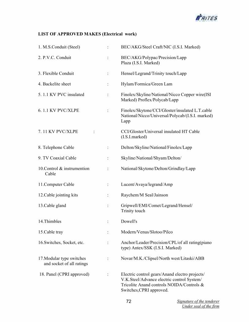
Signature of the tenderer
Under seal of the firm 72
LIST OF APPROVED MAKES (Electrical work)
1. M.S.Conduit (Steel) : BEC/AKG/Steel Craft/NIC (I.S.I. Marked)
2. P.V.C. Conduit : BEC/AKG/Polypac/Precision/Lapp
Plaza (I.S.I. Marked)
3. Flexible Conduit : Hensel/Legrand/Trinity touch/Lapp
4. Backelite sheet : Hylam/Formica/Green Lam
5. 1.1 KV PVC insulated : Finolex/Skyline/National/Nicco Copper wire(ISI
Marked) Proflex/Polycab/Lapp
6. 1.1 KV PVC/XLPE : Finolex/Skytone/CCI/Gloster/insulated L.T.cable
National/Nicco/Universal/Polycab/(I.S.I. marked)
Lapp
7. 11 KV PVC/XLPE : CCI/Gloster/Universal insulated HT Cable
(I.S.I.marked)
8. Telephone Cable : Delton/Skyline/National/Finolex/Lapp
9. TV Coaxial Cable : Skyline/National/Shyam/Delton/
10.Control & instrumention : National/Skytone/Delton/Grindlay/Lapp
Cable
11.Computer Cable : Lucent/Avaya/legrand/Amp
12.Cable jointing kits : Raychem/M Seal/Jainson
13.Cable gland : Gripwell/EMI/Comet/Legrand/Hensel/
Trinity touch
14.Thimbles : Dowell's
15.Cable tray : Modern/Venus/Slotoo/Pilco
16.Switches, Socket, etc. : Anchor/Leader/Precision/CPL/of all rating(piano
type) Antex/SSK (I.S.I. Marked)
17.Modular type switches : Novar/M.K./Clipsel/North west/Litaski/ABB
and socket of all ratings
18. Panel (CPRI approved) : Electric control gears/Anand electro projects/
V.K.Steel/Advance electric control System/
Tricolite Anand controls NOIDA/Controls &
Switches,CPRI approved.
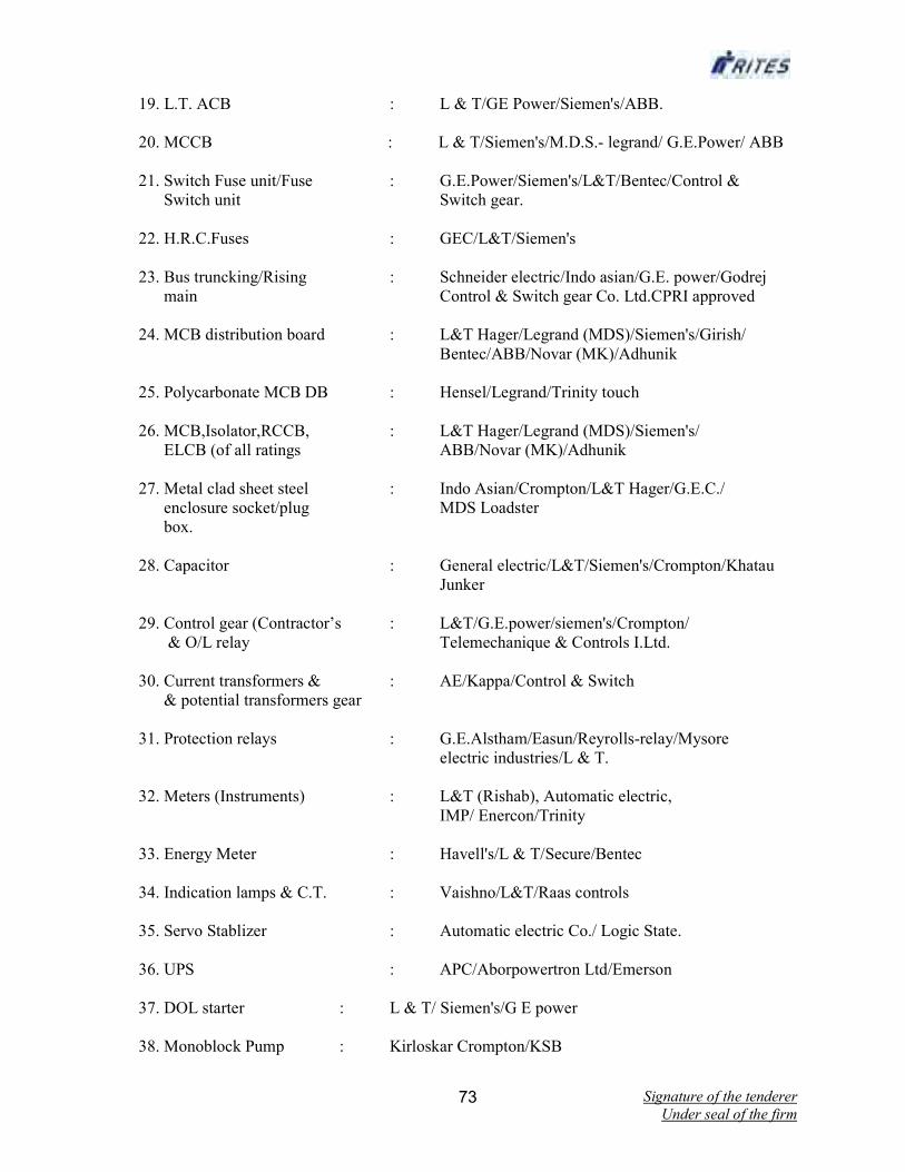
Signature of the tenderer
Under seal of the firm 73
19. L.T. ACB : L & T/GE Power/Siemen's/ABB.
20. MCCB : L & T/Siemen's/M.D.S.- legrand/ G.E.Power/ ABB
21. Switch Fuse unit/Fuse : G.E.Power/Siemen's/L&T/Bentec/Control &
Switch unit Switch gear.
22. H.R.C.Fuses : GEC/L&T/Siemen's
23. Bus truncking/Rising : Schneider electric/Indo asian/G.E. power/Godrej
main Control & Switch gear Co. Ltd.CPRI approved
24. MCB distribution board : L&T Hager/Legrand (MDS)/Siemen's/Girish/
Bentec/ABB/Novar (MK)/Adhunik
25. Polycarbonate MCB DB : Hensel/Legrand/Trinity touch
26. MCB,Isolator,RCCB, : L&T Hager/Legrand (MDS)/Siemen's/
ELCB (of all ratings ABB/Novar (MK)/Adhunik
27. Metal clad sheet steel : Indo Asian/Crompton/L&T Hager/G.E.C./
enclosure socket/plug MDS Loadster
box.
28. Capacitor : General electric/L&T/Siemen's/Crompton/Khatau
Junker
29. Control gear (Contractor’s : L&T/G.E.power/siemen's/Crompton/
& O/L relay Telemechanique & Controls I.Ltd.
30. Current transformers & : AE/Kappa/Control & Switch
& potential transformers gear
31. Protection relays : G.E.Alstham/Easun/Reyrolls-relay/Mysore
electric industries/L & T.
32. Meters (Instruments) : L&T (Rishab), Automatic electric,
IMP/ Enercon/Trinity
33. Energy Meter : Havell's/L & T/Secure/Bentec
34. Indication lamps & C.T. : Vaishno/L&T/Raas controls
35. Servo Stablizer : Automatic electric Co./ Logic State.
36. UPS : APC/Aborpowertron Ltd/Emerson
37. DOL starter : L & T/ Siemen's/G E power
38. Monoblock Pump : Kirloskar Crompton/KSB

Signature of the tenderer
Under seal of the firm 74
39. Transformer : G.E.Alstom Ltd./Crompton/Kanber/ Kirloskar
Electric Co.
40. 11KV Switchgear/VCB : G.E.Alstom Ltd/Crompton/Mysore/Siemen's
M.E.I./ABB/Beclory
41. ACSR Conductor : As approved by Engineer-in-charge
42. Insulator L.T. & H.T : - Do -
43. Tag Block : Krone or Krone type wire less as per specification
(I.S.I)
44. D.G.Set engine : Kisloskar/Cummins/Caterpiller
45. Alternator : Kisloskar/Cummins/AVK/Jyoti/KEC
46. AMF relays : Puneet Industrial Controls.
47. M.S.Stepped tobular pole : ASPL or approved equivalent.
48. RCC/PCC Poles : Hindustan Prefab or an approved equivalent.
49. Ceiling Fans : G.E.Alstoms/Bajaj/Crompton/Khaitan/Orient/
Usha - as approved by Engineer-in-charge.
50. Cabin Fans : Alstoms/Bajaj/Crompton/Khaitan/
51. Exhaust/Axial flow/Ventilation : G.E.Alstoms/Crompton gears
fan
52. Flexible pipe : Lapp/Rodex
53. Light Fixtures/Fittings : Philips/Crompton/Bajaj/KeSelec/Decon/K.Lite
and lamps
54. Heat detector : Appollo/Edward/System Sensor/Novar
55 Smoke detector : Appollo/Edward/System Sensor/Novar
56. Manual call point : AGNI/Alert/Vijay/Prakash/Novar.
57. Response Indicator : AGNI/Alert/Vijay/Prakash/Novar.
58. Hooters : AGNI/Alert/Prakash/Novar.
59. Fire Control panel : AGNI/Prakash/Edward/Novar/
(Main,repeater or zonal) Notifier/Morley.
60. Battery : Exide/Hitechi/SFM Sealed/Prestolite
61. Battery charger : Voltstat/Statcon

Signature of the tenderer
Under seal of the firm 75
62. Paint/Primer : Berger/Asian
63. Loud Speaker : Philips/Ahuja
64. Amplifier : Philips/Ahuja
65. Ceiling Speaker : Philips/Ahuja
66. Any other item : Samples to be produced to the Architect for
approval for use in the work.
Signature of the tenderer
Under seal of the firm 76
LIST OF DRAWINGS ENCLOSED-Nil
Signature of the tenderer
Under seal of the firm 77
PART- 2
FINANCIAL BID

Signature of the tenderer
Under seal of the firm 78
PART - 2
FINANCIAL BID
SCHEDULE (BILL OF QUANTITIES)
NAME OF WORK:-Construction of RPF Office,GRP Barrack & other establishments at
Bolpur,Dt-Birbhum.WB
POINTS TO BE NOTED WHILE QUOTING RATES
1) Where Tender has been invited on Percentage Rate basis, percentages on the Estimated Cost
(whether above or below) are to be quoted for each of the Schedules.
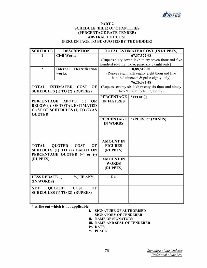
Signature of the tenderer
Under seal of the firm 79
PART 2
SCHEDULE (BILL) OF QUANTITIES
(PERCENTAGE RATE TENDER)
ABSTRACT OF COST
(PERCENTAGE TO BE QUOTED BY THE BIDDER)
SCHEDULE DESCRIPTION TOTAL ESTIMATED COST (IN RUPEES)
1 Civil Works 67,37,572.68
(Rupees sixty seven lakh thirty seven thousand five
hundred seventy two & paise sixty eight only)
2 Internal Electrification
works.
8,88,519.80
(Rupees eight lakh eighty eight thousand five
hundred nineteen & paise eighty only)
TOTAL ESTIMATED COST OF
SCHEDULES (1) TO (2) (RUPEES)
76,26,092.48 (Rupees seventy six lakh twenty six thousand ninety
two & paise forty eight only)
PERCENTAGE ABOVE (+) OR
BELOW (-) OF TOTAL ESTIMATED
COST OF SCHEDULES (1) TO (2) AS
QUOTED
PERCENTAGE
IN FIGURES
* (+) or (-)
PERCENTAGE
IN WORDS
* (PLUS) or (MINUS)
TOTAL QUOTED COST OF
SCHEDULS (1) TO (2) BASED ON
PERCENTAGE QUOTED (+) or (-)
(RUPEES)
AMOUNT IN
FIGURES
(RUPEES)
AMOUNT IN
WORDS
(RUPEES)
LESS REBATE ( %), IF ANY
(IN WORDS)
Rs.
NET QUOTED COST OF
SCHEDULES (1) TO (2) (RUPEES)
* strike out which is not applicable i. SIGNATURE OF AUTHORISED
SIGNATORY OF TENDERER
ii. NAME OF SIGNATORY
iii. NAME AND SEAL OF TENDERER
iv. DATE v. PLACE

Signature of the tenderer
Under seal of the firm 80
E S T I M A T E
SL
No
Description of items Unit Quantity Rate Amount
Schedule – 1 (Civil works)
1 Earthwork in excavation as per approved drawings and
dumping at embankment site or spoil heap,with in
railway land ,including 50 m lead and 1.5m lift,the lead
to be measured from the centre of gravity of
excavation to centre of gravity of spoil heap ;the lift to
be measured from natural ground level and paid for in
layers of 1.5 m each including incidental work,as per
specification all kind of soil.
cum 700.00 88.16 61,712.00
2 Earthwork in excavation as per approved drawings and
dumping at embankment site or spoil heap,with in
railway land ,including 50 m lead and lift more than
1.50m to 3.0 m lift ,the lead to be measured from the
centre of gravity of excavation to centre of gravity of
spoil heap ;the lift to be measured from natural ground
level and paid for in layers of above1.5 m each
including incidental work,as per specification all kind of
soil.
cum 140.00 96.78 13,549.20
3 Filling watering and ramming earth in 15 cm layers in
floors and foundations with surplus earth from
foundations including 50 m lead and 1.5 m lift
cum 840.00 20.40 17,136.00
4 Supplyingand filling sand in plinth and under floors
including watering ,ramming, consolidating, and
dressing complete.
cum 230 359.67 82,724.10
5 Dressing surface (average excavation of filling upto 15
cm ) including removing vegation in all kind of soil
payment against this item is to be made only if it is not
included in earth work item
sqm 200 5.94 1,188.00
7 Providing and laying in position cement concrete of
specified proportion excluding cost of
cement,centering and shuttering-All work upto plinth
level Cement Concrete 1:3:6 (1 cement : 3 coarse sand
: 6 graded stone aggregate 20 mm nominal size )
cum 15 2139.85 32,097.75
8 Providing and laying in position cement concrete of
specified proportion excluding cost of
cement,centering and shuttering-All work upto plinth
level Cement Concrete(1:3:6 1 cement : 3 coarse sand :
6 graded stone aggregate 40 mm nominal size )
cum 80 2002.39 160,191.20
9 Providing and laying in position cement concrete of
specified proportion excluding cost of
cement,centering and shuttering-All work upto plinth
level Cement Cement Concrete(1:5:10)
cum 3 1924.87 5,774.61
10 Making Plinth Protection with bricks of class
designation 7.5 laid on edge in cemeny mortar 1:6 with
12 mm th bed of cement mortar 1:6 over 75 mm bed
of cement dry brick aggregate 40 mm nominal size
rammed ,consolidated and grouted with fine sand and
the top of the bricks pointed with cement mortar 1:3
with non-modular bricks.
Sqm 300 415.33 124,599.00
11 Centering and shuttering including strutting proping
etc and removal of form for Foundations, footings,
bases of columns etc.
Sqm 100 145.90 14,590.00
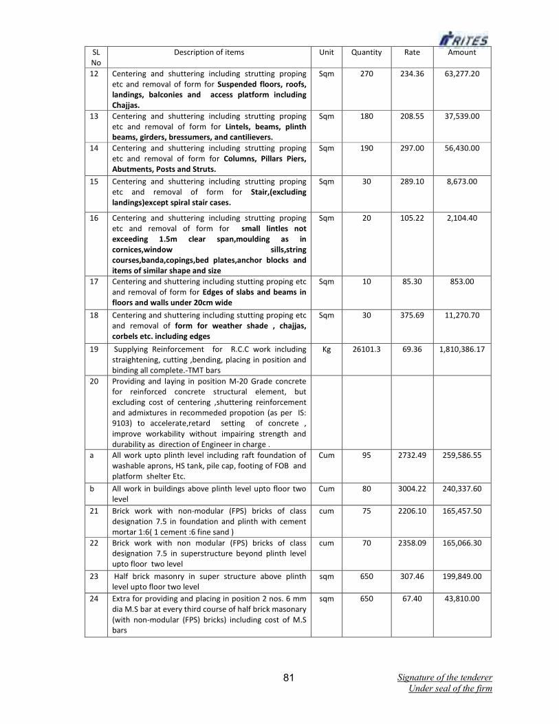
Signature of the tenderer
Under seal of the firm 81
SL
No
Description of items Unit Quantity Rate Amount
12 Centering and shuttering including strutting proping
etc and removal of form for Suspended floors, roofs,
landings, balconies and access platform including
Chajjas.
Sqm 270 234.36 63,277.20
13 Centering and shuttering including strutting proping
etc and removal of form for Lintels, beams, plinth
beams, girders, bressumers, and cantilievers.
Sqm 180 208.55 37,539.00
14 Centering and shuttering including strutting proping
etc and removal of form for Columns, Pillars Piers,
Abutments, Posts and Struts.
Sqm 190 297.00 56,430.00
15 Centering and shuttering including strutting proping
etc and removal of form for Stair,(excluding
landings)except spiral stair cases.
Sqm 30 289.10 8,673.00
16 Centering and shuttering including strutting proping
etc and removal of form for small lintles not
exceeding 1.5m clear span,moulding as in
cornices,window sills,string
courses,banda,copings,bed plates,anchor blocks and
items of similar shape and size
Sqm 20 105.22 2,104.40
17 Centering and shuttering including stutting proping etc
and removal of form for Edges of slabs and beams in
floors and walls under 20cm wide
Sqm 10 85.30 853.00
18 Centering and shuttering including stutting proping etc
and removal of form for weather shade , chajjas,
corbels etc. including edges
Sqm 30 375.69 11,270.70
19 Supplying Reinforcement for R.C.C work including
straightening, cutting ,bending, placing in position and
binding all complete.-TMT bars
Kg 26101.3 69.36 1,810,386.17
20 Providing and laying in position M-20 Grade concrete
for reinforced concrete structural element, but
excluding cost of centering ,shuttering reinforcement
and admixtures in recommeded propotion (as per IS:
9103) to accelerate,retard setting of concrete ,
improve workability without impairing strength and
durability as direction of Engineer in charge .
a All work upto plinth level including raft foundation of
washable aprons, HS tank, pile cap, footing of FOB and
platform shelter Etc.
Cum 95 2732.49 259,586.55
b All work in buildings above plinth level upto floor two
level
Cum 80 3004.22 240,337.60
21 Brick work with non-modular (FPS) bricks of class
designation 7.5 in foundation and plinth with cement
mortar 1:6( 1 cement :6 fine sand )
cum 75 2206.10 165,457.50
22 Brick work with non modular (FPS) bricks of class
designation 7.5 in superstructure beyond plinth level
upto floor two level
cum 70 2358.09 165,066.30
23 Half brick masonry in super structure above plinth
level upto floor two level
sqm 650 307.46 199,849.00
24 Extra for providing and placing in position 2 nos. 6 mm
dia M.S bar at every third course of half brick masonary
(with non-modular (FPS) bricks) including cost of M.S
bars
sqm 650 67.40 43,810.00

Signature of the tenderer
Under seal of the firm 82
SL
No
Description of items Unit Quantity Rate Amount
25 Half brick masonary with bricks of class designation 7.5
in foundation and plinth in cement mortar 1:4
sqm 20 265.31 5,306.20
26 Brick edging 7 cm wde 11.4 cm deep to plinth
protection /along road edges with brick of class
designation 7.5 including grouting with cement
mortar1:4
m 200 19.81 3,962.00
27 Providing and fixing factory made uPVC door frame
made of uPVC extruded section profile size 50mmx
60mm (+/-1 mm)with wall thickness 2 mm +-0.2
mm,corners of door frame to be mitered and joined at
corners by means of plastic,galvanized brackets and
stainless steel screws. Hinge side verticalof frames
reinforced by galvanized MS tube of size 19mmx38 mm
and1mm +/-0.1mm wall thickness and 3 nos stainless
steelhinges fixed to frame complete as per direction of
Engineer in charge.
m 50 292.54 14,627.00
28 Providing and fixing to existing door frame 24 mm thick
factory made PVC door shutters made of style and rails
of a PVC hollow section of size 34 mmx24 mm with a
wall thickness 2mm+/- 0.2 mm.The styles and rails
mitered cut and joined at corners by means of M.S
galvanized /plastic brackets of size 75 mmx220mm
having wall thickness 1.0 mm/solid and fix with stailess
steel screws .The style of shutter reinforced by
inserting galvanized M.S tube of size 19mmx19mm
with a wall thickness 1mm+/- 0.1mm. The shutter
frame filled with a PVC multi chambered single panel of
size 20 mm x762mm with a wall thickness 1 mm+/-
0.1mm .The panels filled vertically and tie bar at two
places by inserting horizentally 0.6mm galvanized M.S
rod and fasstened with nuts and washers. All complete
as per manufacturer's specification and direction of
Engineer-In-Charge.
Sqm 20 1694.99 33,899.80
29 Providing and fixing flush door shutter to Is:2202 part-I
non decorative type, coreof block boardconstruction
with frame of first class hard wood and well matched
commercial 3-ply veneering with vertical grains or
cross bands and face veneers on both faces of shutters
with 30 mm th including ISI marked stainless steel butt
hinges with necessary screws.
Sqm 25 1286.46 32,161.50
30 Providing and fixing M.s door100 mm handles with
necessary screws etc complete.
Each 24 22.15 531.60
31 Providing and fixing M.S sliding door bolts generally
conforming to IS :281,bright satin finish or black stone
enamelled with nuts and screws etc. Complete of size
of250mmx16 mm
Each 12 178.34 2,140.08
32 Providing and fixing M.S tower bolts generally
conforming to IS :204(part I) with necessary screws etc
complete of size 200mmx10mm
Each 40 70.30 2,812.00
33 Providing and fixing aluminium hanging floor Single
rubber door stopper ISI marked anodised (anodic
coating not less than grade AC 10 as per IS:1868
transparent or dyed to required colour and shed with
necessary screws etc complete.
Each 30 37.93 1,137.90
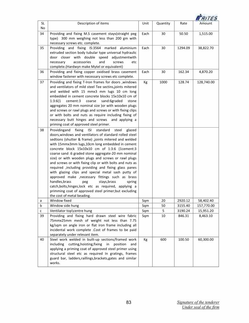
Signature of the tenderer
Under seal of the firm 83
SL
No
Description of items Unit Quantity Rate Amount
34 Providing and fixing M.S casement stays(straight peg
type) 300 mm weighing not less than 200 gm with
necessary screws etc. complete.
Each 30 50.50 1,515.00
35 Providing and fixing IS:3564 marked aluminium
extruded section body tubular type universal hydraulic
door closer with double speed adjustmentwith
necessary accessories and screws etc
complete.(Hardwyn make Mytel or equivalent)
Each 30 1294.09 38,822.70
36 Providing and fixing copper oxidised brass casement
window fastener with necessary screws etc complete.
Each 30 162.34 4,870.20
37 Providing and fixing T-Iron frames for doors ,windows
and ventilators of mild steel Tee sectins,joints mitered
and welded with 15 mmx3 mm lugs 10 cm long
embedded in cement concrete blocks 15x10x10 cm of
1:3:6(1 cement:3 coarse sand:6graded stone
aggregates 20 mm nominal size )or with wooden plugs
and screws or rawl plugs and screws or with fixing clips
or with bolts and nuts as require including fixing of
necessary butt hinges and screws and applying a
priming coat of approved steel primer.
Kg 1000 128.74 128,740.00
38 Providingand fixing ISI standard steel glazed
doors,windows and ventilators of standard rolled steel
sedtions (shutter & frame) ,joints mitered and welded
with 15mmx3mm lugs,10cm long embedded in cement
concrete block 15x10x10 cm of 1:3:6 (1cement:3
coarse sand :6 graded stone aggregate-20 mm nominal
size) or with wooden plugs and screws or rawl plugs
and screws or with fixing clip or with bolts and nuts as
required ,including providing and fixing glass panes
with glazing clips and special metal sash putty of
approved make ,necessary fittings such as brass
handles,brass peg stays,brass spring
catch,bolts,hinges,lock etc as required, applying a
primming coat of approved steel primer;but excluding
the cost of metal beading.
a Window fixed Sqm 20 2920.12 58,402.40
b Window side hung Sqm 50 3155.40 157,770.00
c Ventilator top\centre hung Sqm 5 3190.24 15,951.20
39 Providing and fixing hard drawn steel wire fabric
75mmx25mm mesh of weight not less than 7.75
kg/sqm on angle iron or flat iron frame including all
incidental work complete .Cost of frames to be paid
separately under relevant item.
Sqm 10 846.31 8,463.10
40 Steel work welded in built-up sections/framed work
including cutting,hoisting,fixing in position and
applying a priming coat of approved steel primer using
structural steel etc as required In gratings, frames
guard bar, ladders,raillings,brackets,gates and similar
works.
Kg 600 100.50 60,300.00

Signature of the tenderer
Under seal of the firm 84
SL
No
Description of items Unit Quantity Rate Amount
41 Providing and fixing in position collapose steel
shutters with vertical channels 20mm x 10mmx 2 mm
and braced with flat iron diagonals 20mmx 5mmx5mm
size with top & bottom rail of T- iron
40mmx40mmx6mm with 40mm dia. Steel pulleys
complete with bolts nuts, locking arrangement,
stoppers, handles and hold fasts including applying a
priming coat of approved steel primer.
sqm 6.3 3457.49 21,782.19
42 Cement concrete flooring 1:2:4 finished with a floating
coat of neat cement including cement slurry but
excluding the cost of nosing of steps etc complete( 40
mm thick with 20 mm nominal size stone aggregate)
Sqm 100 138.25 13,825.00
43 Cement plaster 18 mm th. skirting (up to 30 cm height)
with cement mortar1:3(1 cement:3 coarse sand)
finished with a floating coat of neat cement.
Sqm 220 118.29 26,023.80
44 Providing and fixing glass strips in joints of
terrazzo/cement concrete floors 40 mm deep and 4
mm thick in joints of terrazo/ cement concrete floors.
m 500 27.57 13,785.00
45 Kota stone slab flooring 20 mm thick of size up to
60cmx60cm over 20 mm (average) thick base of 1:4
cement mortar (1 cement:4 coarse sand) and jointed
with gray cement slurry mixed with pigment to match
the shade of the slab including rubbing and polishing
complete.
Sqm 300 1169.69 350,907.00
46 Kota stone slab 25 mm thick in riser of steps , skirting
,dado and pillars laid on12 mm(average) thick cement
mortar 1:3 (1 cement :3 coarse sand) and jointed with
grey cement slurry mixed withpigment to match the
slab ,including rubbing and polishing complete:
Sqm 60 1031.57 61,894.20
47 Providing and fixing 1 st quality ceramic tiles 200x200
mm conforming to group B-III (Ceramic wall tiles) of IS
;15622 of manufactures approved by railway in all
colours ,shades,and design as approved by the
Engineer -in- charge in skirting,riser of steps and dado
over 12 mm th bed of cement mortar 1:3 )1 cement:3
coarse sand) including pointing in white cement mixed
with pigment of matching shade complete
Sqm 150 673.21 100,981.50
48 Providing and fixing ceramic tiles conforming to IS:
15622 of manufactures approved by railway in all
colours,shades,design and abrasion resistance class as
approved by the Engineer -in -Charge in floors and
landings over 20mm thick bed of cement mortar 1:4( 1
cement:3 coarse sand) including pointing in white
cement mixed with pigment of matching shade
complete of Group-B-1-a of IS: 15622(Vitrified tiles) of
size above 400mm x 400mm upto 600mm x 600mm
Sqm 100 1102.32 110,232.00
49 12 mm cement plaster of mix 1: 6 ( 1 cement :6 fine
sand )
Sqm 900 62.44 56,196.00
50 15 mm cement plaster on the rough side of single or
half brick wall of mix 1:6( 1 cement :6 fine sand )
Sqm 800 71.55 57,240.00
51 Cement plaster to ceiling of mix of 6 mm cement
plaster of mix 1:3 ( 1 cement :3 fine sand )
Sqm 700 55.56 38,892.00
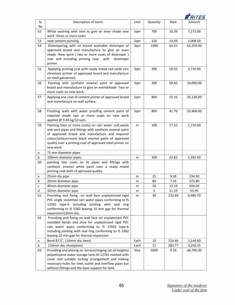
Signature of the tenderer
Under seal of the firm 85
SL
No
Description of items Unit Quantity Rate Amount
52 White washing with lime to give an even shade new
work -three or more coats
Sqm 700 10.39 7,273.00
53 neat cement punning Sqm 150 13.39 2,008.50
54 Distempering with oil bound washable distemper of
approved brand and manufacture to give an even
shade -New work ( two or more coats of distemper )
over and including priming coat with distemper
primer.
Sqm 1000 63.25 63,250.00
55 Applying priming coat with ready mixed red oxide zinc
chromate primer of approved brand and manufacture
on steel galvanised.
Sqm 200 18.55 3,710.00
56 Painting with synthetic enamel paint of approved
brand and manufacture to give an evendshade- Two or
more coats on new work.
Sqm 200 50.45 10,090.00
57 Applying one coat of cement primer of approved brand
and manufacture on wall surface.
Sqm 800 25.16 20,128.00
58 Finishing walls with water proofing cement paint of
required shade two or more coats on new work
applied @ 3.84 kg/10 sqm.
Sqm 800 41.76 33,408.00
59 Painting (two or more coats) on rain water ,soil,waste
and vent pipes and fittings with synthetic enamel paint
of approved brand and manufacture and required
colour/anticorrosive black enamel paint of approved
quality over a priming coat of approved steel primer on
new work
m 100 17.10 1,710.00
a 75 mm diameter pipes
b 100mm diameter pipes. m 100 22.82 2,282.00
60 painting two coats on GI pipes and fittings with
synthetic enamel white paint over a ready mixed
priming coat both of aptroved quality
a 25mm dia pipe m 25 9.38 234.50
b 20mm diameter pipe. m 80 7.16 572.80
c 40mm diameter pipe. m 50 13.19 659.50
d 32mm diameter pipe. m 5 11.19 55.95
61 Providing and fixing on wall face unplasticised rigid
PVC single socketted rain water pipes conforming to IS
13592 type-A including jointing with seal ring
conforming to IS 5382 leaving 10 mm gap for thermal
expansion110mm dia.
m 30 232.69 6,980.70
62 Providing and fixing on wall face on unplaticised PVC
moulded bends and shoe for unplasticised rigid PVC
rain water pipes conforming to IS 13592 type-A
including jointing with seal ring conforming to IS 5382
leaving 10 mm gap for thermal expansion-
a Bend 87.5°, 110mm dia, bend. Each 10 214.46 2,144.60
b 110mm dia, shoe(plain). Each 15 283.77 4,256.55
63 Providing and placing on terrace/staging (at all heights)
polyethylene water storage tank ISI:12701 marked with
cover and suitable locking arrangement and making
necessary holes for inlet, outlet and overflow pipes but
without fittings and the base support for tank.
litre 5000 9.34 46,700.00
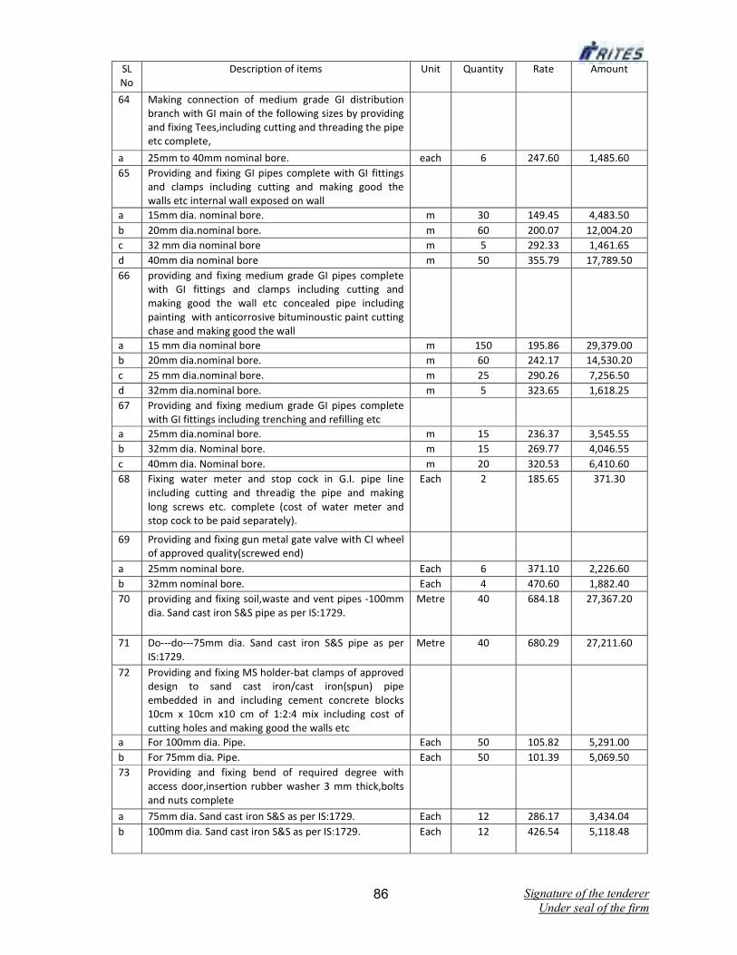
Signature of the tenderer
Under seal of the firm 86
SL
No
Description of items Unit Quantity Rate Amount
64 Making connection of medium grade GI distribution
branch with GI main of the following sizes by providing
and fixing Tees,including cutting and threading the pipe
etc complete,
a 25mm to 40mm nominal bore. each 6 247.60 1,485.60
65 Providing and fixing GI pipes complete with GI fittings
and clamps including cutting and making good the
walls etc internal wall exposed on wall
a 15mm dia. nominal bore. m 30 149.45 4,483.50
b 20mm dia.nominal bore. m 60 200.07 12,004.20
c 32 mm dia nominal bore m 5 292.33 1,461.65
d 40mm dia nominal bore m 50 355.79 17,789.50
66 providing and fixing medium grade GI pipes complete
with GI fittings and clamps including cutting and
making good the wall etc concealed pipe including
painting with anticorrosive bituminoustic paint cutting
chase and making good the wall
a 15 mm dia nominal bore m 150 195.86 29,379.00
b 20mm dia.nominal bore. m 60 242.17 14,530.20
c 25 mm dia.nominal bore. m 25 290.26 7,256.50
d 32mm dia.nominal bore. m 5 323.65 1,618.25
67 Providing and fixing medium grade GI pipes complete
with GI fittings including trenching and refilling etc
a 25mm dia.nominal bore. m 15 236.37 3,545.55
b 32mm dia. Nominal bore. m 15 269.77 4,046.55
c 40mm dia. Nominal bore. m 20 320.53 6,410.60
68 Fixing water meter and stop cock in G.I. pipe line
including cutting and threadig the pipe and making
long screws etc. complete (cost of water meter and
stop cock to be paid separately).
Each 2 185.65 371.30
69 Providing and fixing gun metal gate valve with CI wheel
of approved quality(screwed end)
a 25mm nominal bore. Each 6 371.10 2,226.60
b 32mm nominal bore. Each 4 470.60 1,882.40
70 providing and fixing soil,waste and vent pipes -100mm
dia. Sand cast iron S&S pipe as per IS:1729.
Metre 40 684.18 27,367.20
71 Do---do---75mm dia. Sand cast iron S&S pipe as per
IS:1729.
Metre 40 680.29 27,211.60
72 Providing and fixing MS holder-bat clamps of approved
design to sand cast iron/cast iron(spun) pipe
embedded in and including cement concrete blocks
10cm x 10cm x10 cm of 1:2:4 mix including cost of
cutting holes and making good the walls etc
a For 100mm dia. Pipe. Each 50 105.82 5,291.00
b For 75mm dia. Pipe. Each 50 101.39 5,069.50
73 Providing and fixing bend of required degree with
access door,insertion rubber washer 3 mm thick,bolts
and nuts complete
a 75mm dia. Sand cast iron S&S as per IS:1729. Each 12 286.17 3,434.04
b 100mm dia. Sand cast iron S&S as per IS:1729. Each 12 426.54 5,118.48

Signature of the tenderer
Under seal of the firm 87
SL
No
Description of items Unit Quantity Rate Amount
74 Providing and fixing plain bend of required degree
a 75mm dia. Sand cast iron S&S as per IS:1729. Each 10 243.17 2,431.70
b 100mm dia. Sand cast iron S&S as per IS:1729. Each 10 288.63 2,886.30
75 Providing and fixing single equal plain junction of
required degree
a 100mmx100mmx100mm sand cast iron S&S as per
IS:1729.
Each 10 401.88 4,018.80
b 75mmx75mmx75mm sand cast iron S&S as per IS:1729. Each 10 298.45 2,984.50
76 Providing and fixing Single unequal plain junction of
required degree.
a 100mmx100mmx75mm sand cast iron S&S as per
IS:1729.
Each 10 493.60 4,936.00
77 Providing and fixing terminal guard
a 100mm sand cast iron S&S as per IS:1729. Each 10 298.13 2,981.30
b 75mm sand cast iron S&S as per IS:1729. Each 10 169.15 1,691.50
78 Providing ,Laying and jointing glazed stoneware pipes
grade "A" as per IS :651 including bendsetc.with stiff
mixture of cement mortar in the proportion of 1:1(1
cement:1fine sand) including testing of joints etc
complete.
a 150mm diameter. m 40 308.87 12,354.80
79 providing and laying cement concrete 1:5:10(1
cement:5 coarse sand:10 grade stone aggregate 40 mm
nominal size ) upto haunches of S.W pipes including
bed concrete as per standard design
a 150mm diameter S.W. pipe. m 40 219.44 8,777.60
80 Makiing soak pit 2.5m diameter, 3m deep with
45cmx45cm dry brick honey comb shaft with bricks-FPS
bricks- of class designation 7.5 and S.W. drain pipes
100mm diameter, 1.8m long complete as per standard
design, including excavation complete.
Each 2 12619.61 25,239.22
81 Providing and fixing square mouth S.W gulley trap
grade "A" complete with C.I grating brick masonry
chamber with water tight C.I cover with frame of
300x300 mm size (inside) the weight of cover to be not
less than 4.50 Kg and frame to be not less than 2.7 kg
as per standard design.
a 150mmx100mm size 'P' type with F.P.S. bricks class
designation 7.5.
Each 10 1266.81 12,668.10
82 Making connection of drain sewer line with existing
manhole including breaking into and making good the
walls , floor with cement concrete 1:2:4 mix(1
cement:2 coarse sand:4 graded stone aggregates 20
mm nominal size)cement plastered on both sides with
cement mortar 1:3 (1cement :3 coarse sand)finished
with a floating coat of neat cement and making
necessary channels for the drain etc comlete.
a For pipes 100mm to 230mm dia. Each 15 184.55 2,768.25

Signature of the tenderer
Under seal of the firm 88
SL
No
Description of items Unit Quantity Rate Amount
83 Constructing brick masonry chamber for under ground
C.I inspection chamber and bends with 7.5 class
designation bricks in cement mortar 1:4(1 cement:4
coarse sand) C.I cover with frame (light duty) 455
mmx610 mm internal dimension ,total weight of cover
with frame to be not less than 38 kg(weight of cover23
kg and weight of frame15 kg) R.C.C top slab with1:2:4
mix (1 cement:2coarse sand:4 graded stone aggregate
20 mm nominal size) foundation concrete 1:5:10 (1
cement:5 fine sand: 10 gradeded stone aggeregate 40
mm nominal size ),inside plastering 12 mm thick with
cement mortar1:3(1cement :3 coarse sand) finished
smooth with a floating coat of neat cement on walls
and bed concrete etc.complete as per standard design
a Inside dimensions 500mmx700mm and 45cm deep for
pipe line with one or two inlets with F.P.S. bricks.
Each 10 3481.80 34,818.00
84 Constructing brick masonry manhole in cement mortar
1:4(1 cement :4 coarse sand) R.C.C topslab with 1:2:4(1
cement :2 coarse sand:4 graded stone aggregate 20
mm nominal size),foundation concrete 1:4:8 mix (1
cement:4 coarse sand:8 graded stone aggregates 40
mm nominal size) inside plastering 12 mm thick with
cement mortar 1:3 (1 cement:3 coarse sand) finished
with floating coat of neat cement and making channels
in cement concrete 1;2:4 (1 cement:2:coarse sand:4
graded stone aggregate 20 mm nominal size )finished
with a floating coat of neat cement concrete as per
standard design
a Inside size 90cmx80cm and 45cm deep including C.I.
cover with frame (light duty) 455mmx610mm internal
dimensions total weight of cover and frame to be not
less than 38 kg (weight of cover 23kg and weight of
frame 15kg) with F.P.S> brickes class designation 7.5.
Each 6 4673.34 28,040.04
85 Providing and fixing stainless steel AISI304 (18/8)
kitchen sink with drain board as per IS:13983 with C.I
Brackets and stainless steel plug 40 mm including
painting of fitting and brackets,cutting and making
good the walls whenever required.
a 510mmx1040mm bowl depth 250 mm Each 2 6262.30 12,524.60
86 Providing and fixing Basin /sink waste (C.P Brass)
coupling with chain and stopper complete
a Waste 32 mm Each 2 130.36 260.72
87 Providing and fixing P.V.C waste pipe for sink or wash
basin including P.V.C waste fittings complete
a flexible pipe 32 mm dia Each 12 78.20 938.40
88 Providing and fixing C.P brass bib cock, 15 mm nominal
bore of approved quality conforming to Is:8931
Each 10 469.88 4,698.80
89 Providing and fixing C.P brass stop cock,15 mm
nominal bore,(concealed) of standard design and of
approved make conforming to IS 8931
Each 10 404.48 4,044.80

Signature of the tenderer
Under seal of the firm 89
SL
No
Description of items Unit Quantity Rate Amount
90 Providing and fixing wash basin with C.I/M.s
brackets,15 mm C.P brass pillar taps,32 mm C.P brass
waste of standard pattern,including painting and
fittings and brackets,cutting and making good the walls
wherever required White vitreous china flat back wash
basin size550mmx400mm with single 15 mm C.P brass
pillar tap
Each 8 1435.23 11,481.84
91 Providing and fixing white vitreous china flat black or
wall corner type lipped front urinal basin of
430mmx260mmx350mm and 340mmx 410mmx 265
mm size respectively with automatic flushing cistern
,with stasndard flush pipe and C.P brass spreaders with
brass unions and G.I clamps complete,including
painting of fittings and brackets ,cutting and making
good the walls and floors ,wherever required.
a Range of four urinal basin with 15 litres white P.v.c
automatic flushing cistern.
Each 3 8275.13 24,825.39
92 Providing and fixing C.P brass shower rose with 15 mm
or 20 mm inlet
a 100 mm diameter Each 4 233.07 932.28
93 Providing and fixing C.P brass long nose bib cock ,15
mm nominal bore ,of approved quality conforming to
IS standards and weighing not less than 810 gm
Each 10 464.19 4,641.90
94 providing and fixing white vitreous china pedestral
type water closet (European type w.c pan) with seat
and lid ,10 litres low level white P.V.C flushing cistern
with manually controlled device (handle lever)
conforming to IS :7231, with all fittings and fixtures
complete including cutting and making good the walls
and floors wherever required,
a W.C pan with ISI marked white solid plastic seat and
lid
Each 6 2986.84 17,921.04
95 providing and fixing water closet sqatting pan (Indian
type W.Cpan) with 100 mm sand cast iron "p" or "s"
trap , 10 lts low level white PVC flushing cistern with
mannually controlled device ,(handle lever) conforming
to IS 7231, with all fittings and fixtures complete
including cutting and making good the walls and floors
wherever required.
a white vitreous China Orrissa pattern W.c pan of size
580mm x 440mm with intregal type foot rests.
Each 6 3128.93 18,773.58
96 Providing and fixing towel ring (C.P) of approved make
170 mm dia having approx . Weight 490 gm
Each 5 185.09 925.45
97 Providing and fixing C.P brass soap dish holder having a
length of 138 mm ,102mm wide, 75mm high with
concealed fitting arrangements weighing approx 110
gm
Each 5 162.36 811.80
98 Providing and fixing mirror of 5.5 mm thickness of float
glass (of approved quality)required shape and size with
plastic moulded frame of approved make and shade
with 6 mm thick hard board backing.
a Rectangular shape 453mmx357 mm (outer dimension) Each 5 810.94 4,054.70
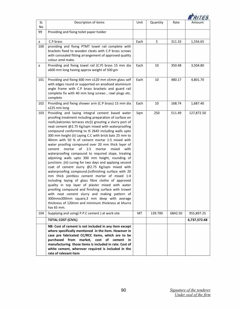
Signature of the tenderer
Under seal of the firm 90
SL
No
Description of items Unit Quantity Rate Amount
99 Providing and fixing toilet paper holder
a C.P brass Each 5 311.33 1,556.65
100 providing and fixing PTMT towel rail complete with
brackets fixed to wooden cleats with C.P brass screws
with concealed fitting arrangement of approved quality
colour amd make.
a Providing and fixing towel rail (C.P) brass 15 mm dia
x600 mm long having approx weight of 500 gm
Each 10 350.48 3,504.80
101 Providing and fixing 600 mm x120 mm x5mm glass self
with edges round or supported on anodised aluminium
angle frame with C.P brass brackets and guard rail
complete fix with 40 mm long screws , rawl plugs etc.
complete
Each 10 480.17 4,801.70
102 Providing and fixing shower arm (C.P brass) 15 mm dia
x225 mm long
Each 10 168.74 1,687.40
103 Providing and laying integral cement based water
proofing treatment including preparation of surface on
roofs,balconies terraces etc(i) grouting a slurry port of
neat cement @2.75 Kg/sqm mixed with waterproofing
compound conforming to IS 2645 including walls upto
300 mm height (ii) Laying C.C with brick bats 25 mm to
40mm with 50 % of cement mortar 1:5 mixed with
water proofing compound over 20 mm thick layer of
cement mortar of 1:5 mortar mixed with
waterproofing compound to required slope, treating
adjoining walls upto 300 mm height, rounding of
junctions .(iii) curing for two days and applying second
coat of cement slurry @2.75 Kg/sqm mixed with
waterproofing compound.(iv)finishing surface with 20
mm thick jointless cement mortar of mixed 1:4
including laying of glass fibre clothe of approved
quality in top layer of plaster mixed with water
proofing compound and finishing surface with trowel
with neat cement slurry and making pattern of
300mmx300mm square,3 mm deep with average
thickness of 120mm and minimum thickness at khurra
has 65 mm.
Sqm 250 511.49 127,872.50
104 Supplying and using( P.P.C cement ) at work site MT 139.700 6842.50 955,897.25
TOTAL COST (CIVIL) 6,737,572.68
NB: Cost of cement is not included in any item except
where specifically mentioned in the item. However in
case pre fabricated CC/RCC items, which are to be
purchased from market, cost of cement in
manufacturing those items is included in rate. Cost of
white cement, wherever required is included in the
rate of relevant item

Signature of the tenderer
Under seal of the firm 91
SL
No
Description of items Unit Quantity Rate Amount
Schedule- 2 (A) Internal Electrification works
SI.
No.
Description of Items Unit Qty Rate per
Unit
Amount
Total Rs.
1 Supply, installation, testing & commissioning of 2 X 4'-
0''x18w T -5, Batten type fluorescent light titting
indoor conforming to IS 10322 Part-5, section 2/82
with Electronic ballast, PF improvement capacitor,
starter, rotary holders, ete., including lamp, supply,
connection from ceiling rose using 3 Core PVC flexible
chord wire using wooden round blocks, M.S. down rod
M.S. bracket pipe on wall. etc., fIXing arrangement
suitable at site locations, etc., (Inside Service Building).
(Make: Phillips, Bajaj, Havells)
No. 40 1958.00 78320.00
2 Supply, fixing, testing & commissioning of AC Ceiling
Fan 1200 mm sweep (confirming to IS 374/79) with
tive star marking ( ••••• ) complete with double ball
bearing, condenser, etc. in the ceiling of building with
suitable hooking arrangements with flush mounting,
supply, connection from ceiling rose 3 core PVC
flexible chord wire as per standards.
No. 30 1932.00 57960.00
3 Supply, fixing, testing & commissioning of Electronic
Fan Regulator (Flush type) 200V complete with
provision of new termination on decolom TW
board.(OSWAL / RIDER /ANCHOR)
No. 30 191.10 5733.00
4 Supply,fixing,testing & commssioning of Exhaust Fan
450mm including wall opening with plastering for
housing exhaust fan with 3 core x 1.5 sqmm PVC
insulated copper cable .(Make : Bajaj.Havells, Usha)
No 8 2981.25 23850.00
5 Supply fIXing, testing & commissioning of CFL Bracket
light fittings, holder alongwith 18W CFL lamp
No. 25 225.00 5625.00
6 Supply & wiring for light point / fan point / exhaust fan
point /call bell point / 5A plug point with PVC
insulated copper conductor single core cable of size1.5
sq.mm -2 nos. & 1 no. 14SWG tinned copper wire for
earth continuity in recessed PVC conduit, including
provision of control switches terminating on a
decoIom finish TW board with testing &
commissioning. (Reputed ISI mark)
Point 25 499.00 12475.00
7 Wiring for circuit/sub main wiring alongwith earth
wire of the following sizes of PVC insulated copper
conductor, single core cable in surface / recessed PVC
conduit as required
(j) 2 x 2.5 sq.mm + 1 x 2.5 sq.mm Mtr. 100 131.00 13100.00
(ii) 2x 4 sq.mm + 1 x4sq.mm Mtr. 60 162.00 9720.00
(iii) 4x6sq.mm + 2x6sq.mm Mtr. 40 358.00 14320.00
8 Supplying and fixing following piano type switch /
socket on existing switching box J cover including
connections etc. as required (Make: Anchor, Havells,
Capri)
0.00
(i) 3 pin 5/6 amps socket outlet No. 20 35.50 710.00
(ii) 15/16 amps switch No. 10 61.50 615.00
(iii) 6 pin 15/16 amps socket outlet No. 5 73.00 365.00

Signature of the tenderer
Under seal of the firm 92
SL
No
Description of items Unit Quantity Rate Amount
9 Supplying and fixing following size I modules, GI box
alongwith modular base & cover plate modular
switches in recess etc. as required
(I) 1 or 2 module (75 mm x 75 mm) No. 40 142.00 5680.00
10 Supplying and fixing following size PVC conduit along
with accessories in surface / recess including cutting
the wall and making good the same in case of
recessed conduit as required
(i) 25 mm Mtr 200 64.50 12900.00
11 Supplying and fIxing following way, single pole and
neutral, prewired, sheet steel, MCB distribution board,
240 volts, on surface I recess, complete with loose
wire box, terminal blocks, duly prewired with suitable
size FR PVC insulated copper conductor up to terminal
blocks, tinned copper busbar, neutral link, earth bar,
din bar, detachable gland plate, interconnections,
phosphatized and powder cainted includlna earthina
etc. as reouired. (But without MCB/RCCB/Isolator)
2 + 4 way, Single door Each 10 1717.00 17170.00
12 Supplying and fIXing 5 amps to 32 amps rating, 240
volts, 'B' series, MCB suitable for lighting and other
loads of the following poles in the existing MCB DB
cornolete with connections, testing and
(i) Single pole Each 2 98.90 197.80
13 Meter & Panel Set 1 3509.00 3509.00
Supply & fixing of cubical type metal board fablicated
with 16SWG MS sheet duly painted with primer and
two coats of approved paint, of size 300 X 250 X 200
mm complete with following fittings
(a) Wooden plank for fixing meter in each
compartment
(b) Supply and fIXing double pole of 32 A ELCB Isolator
for each meter.
(c) House Service meter single phase, Non drawable
type, Amps 10- 20 make GEC, and connections of
above items to supply in all respect complete as
required
Sub Total (A) 262249.80

Signature of the tenderer
Under seal of the firm 93
SL
No
Description of items Unit Quantity Rate Amount
Schedule- 2 (B)
1 Supply, testing and commissioning of XLPEinsu!ated
and PVC sheathed aluminium conductor armoured
power cable 1.1 KV grade conforming to IS: 7098(Part-
1) of following sizes
i) 3.5x35sqmm Mtr 300 308.76 92628.00
ii) 3.5x50 sq mm Mtr 300 398.45 119535.00
2 Laying of one number PVC insulated and PVC
sheathed/XLPE aluminium conductor armoured power
cable 1100 Volt grade directly in ground including
excavation, sand cushioning, protective covering of
brick and refilling of trench etc. as required at site of
size 25 sqmm including road crossing
Mtr 600 109.20 65520.00
3 Supplying & laying of 100mm dia ( G.I pipe) for
tracklroad crossing as required and as per the
direction of Engineer-in-Charge including MV cable
laying of 25 sqmm in the pipe leading in walls
Mtr 100 619.88 61988.00
4 Supply, installation, connection, testing and
commissioning of 40mm dia, 3 metre long G.I. Pipe
earth electrodes, complete with pit and all necessary
materials including excavation of earth pit, filling with
Charcoal and salt, back filling around the GJ. Pipe
earth electrodes and complete including
supply/leadingl1aying/burring and concealing of
4SWG GI Wire from earth electrode to proposed
MOB/SOB of elseWhere and in manner as per
standards.
Nos 4 2537.00 10148.00
5 Supply and installation of factory fabricated and wired
metal clad, dust complete with following MCBslHRC
fuses and instrument chamber and vermin proof,
floorlwall mounting panel TPN switch Board etc.
complete in all respect. The board shall have TPN
Aluminium Bus Bar as per IS: The switches shall be
complete with suitable cable sockets, compression
glands. The switch board shall be cubicle type,
fabricated from 1.6 mm thick CRCA sheet and duly
painted as per specifications as required.
Set 1 33000.00 33000.00
Incoming (O/S Dormitory and Half O/S Dormitory)
2x 125 A TPN FSU with 100 Amps HRC Fuses, and 200
Amps AI Bus Bar
Outgoing
40 Amps. 4 Pole MCB -5 Nos.
6 Supply, Errection & Commisioning of 9 mtr length
Tubuler pole having cross arm bracket of length 1.5
mtr, top cap etc.
No 8 15870.00 126960.00
7 OPTAL 1 New -IP 66 Architectural Street light in
pressure die cast aluminium in two tone color with
ocean green on top cover & contrasting light grey
finish on bottom suitable for low wattage HID lamps
with sagged tempered glass lense 1x150W MH (T)
(E27) Housing ballast with lamp.
No 8 5530.00 44240.00

Signature of the tenderer
Under seal of the firm 94
SL
No
Description of items Unit Quantity Rate Amount
8 Erection of tubler pole with required fittings and cable
jointing arrangement.
No 8 2803.00 22424.00
(a) Supply of XLPE Al armoured LT cable, 4 X 16 sq.mm
1100 volt grade.
Mtrs 200 209.00 41800.00
(b) Laying of cable / cables in under ground along the
road through cable trench etc . as per standard
drawing including necessary termination , connection
and testing.
Mtrs 100 80.27 8027.00
Sub Total – Schedule 2 (B) 626270.00
Grand Total of Schedule – 2 (A) + 2 (B) 888519.80