Contaminated land: dealing with hydrocarbon contamination Assessing risks to other receptors.

Risks of Contaminated Land to Buildings, BuildingMaterials and Services
A literature review
Research and DevelopmentTechnical Report
P331

Research Contractor:BRE (and M A Smith Environmental Consultancy)
Risks of contaminated land to buildings, buildingmaterials and services A literature review
R&D Technical Report P331
Stephen Garvin, Richard Hartless, Mike Smith, Steven Manchester and Paul Tedd
Publishing OrganisationEnvironment AgencyRio HouseWaterside DriveAztec WestAlmondsburyBristol BS32 4UD
Tel: 01454 624400 Fax: 01454 624409
ISBN: 1 85705 247 1
© Environment Agency 2000
All rights reserved. No part of this document may be produced, stored in a retrieval system, ortransmitted, in any form or by any means, electronic, mechanical, photocopying, recording orotherwise without the prior permission of the Environment Agency.
The views expressed in this document are not necessarily those of the Environment Agency.Its officers, servants or agents accept not liability whatsoever for any loss or damage arisingfrom the interpretation or use of the information, or reliance upon the views contained herein.
Dissemination statusInternal: Released to RegionsExternal: Public Domain
Statement of UseThis document provides a literature review of information on the assessment and managementof risks from land contamination to buildings and can be used by Environment Agencyofficers, consultants, industry and others for information on such literature.
Research ContractorThis document was produced under R&D Project P5-035 by:
BRE (and M A Smith Environmental Consultancy)Bucknalls LaneGarstonWatfordHertsWD2 7JR
Tel: 01923 664000 Fax: 01923 664010
Environment Agency Project ManagerThe Environment Agency’s Project Manager for R&D Project P5-035 wasJane Morris, Head Office

R&D Technical Report P331 Page i
CONTENTS
1 INTRODUCTION........................................................................................................................................ 3
1.1 BACKGROUND............................................................................................................................................ 31.2 SCOPE AND STRUCTURE OF THE LITERATURE REVIEW............................................................................... 41.3 REFERENCES (SECTION 1) .......................................................................................................................... 6
2 BUILDING MATERIALS IN CONTAMINATED LAND ...................................................................... 8
2.1 BACKGROUND............................................................................................................................................ 82.2 GENERAL PRINCIPLES .............................................................................................................................. 102.3 CONCRETE ............................................................................................................................................... 122.4 REINFORCED CONCRETE .......................................................................................................................... 272.5 ASBESTOS CEMENT.................................................................................................................................. 312.6 MASONRY................................................................................................................................................ 322.7 METALS ................................................................................................................................................... 352.8 ORGANIC MATERIALS .............................................................................................................................. 422.9 PROBLEM INVESTIGATION AND REMEDIAL ACTION ................................................................................. 502.10 IMPLEMENTATION OF RISK MANAGEMENT ACTION.................................................................................. 512.11 CONCLUSIONS .......................................................................................................................................... 522.12 REFERENCES (SECTION 2) ........................................................................................................................ 53
3. SUBTERRANEAN FIRES ............................................................................................................................. 85
3.1 BACKGROUND.......................................................................................................................................... 853.2 SURVEYS.................................................................................................................................................. 853.3 HAZARDS ................................................................................................................................................. 853.4 SITE INVESTIGATION AND RISK ASSESSMENT........................................................................................... 863.5 EVALUATION AND SELECTION OF REMEDIAL MEASURES........................................................................... 863.6 CONCLUSIONS .......................................................................................................................................... 863.7 REFERENCES (SECTION 3) ........................................................................................................................ 87
4. BUILDING ON FILL...................................................................................................................................... 88
4.1 BACKGROUND.......................................................................................................................................... 884.2 HAZARDS ................................................................................................................................................. 884.3 RISK ASSESSMENT.................................................................................................................................... 884.4 GROUND WATER LEVEL AND FLOW......................................................................................................... 894.5 EVALUATION AND SELECTION OF REMEDIAL MEASURES........................................................................... 894.6 CONCLUSIONS .......................................................................................................................................... 894.7 REFERENCES (SECTION 4) ........................................................................................................................ 89
5. EXPANSIVE SLAGS ...................................................................................................................................... 91
5.1 HAZARD ................................................................................................................................................... 915.2 BACKGROUND.......................................................................................................................................... 915.3 SLAG STABILITY....................................................................................................................................... 945.4 RISK ASSESSMENT .................................................................................................................................... 975.5 EVALUATION AND SELECTION OF REMEDIAL MEASURES......................................................................... 1015.6 REFERENCES (SECTION 5) ...................................................................................................................... 102

R&D Technical Report P331 Page 1
EXECUTIVE SUMMARY
This literature review is concerned with the risks from contaminated land to buildings,building materials and services and provides a summary of relevant international literaturethat is available on the subject. The report is structured into five sections, as follows:
Section 1 IntroductionSection 2 Building materials in contaminated landSection 3 Subterranean firesSection 4 Building on fillSection 5 Expansive slags
In 1994 the Building Research Establishment (BRE) published BRE Report, BR255, theperformance of building materials in contaminated land. This was an extensive reportcovering the mechanisms of chemical attack by contaminants on building materials andaspects of risk management. In the intervening period there has been research reported on theperformance of building materials in aggressive environments. Whilst not all of this researchis specific to the contaminated land environment, other aggressive situations are relevant andguidance can be developed from these situations.
The sections on subterranean fires and risks posed by expansive slags cover specific problems.Whilst these risks are of concern they affect only a limited number of contaminated sites in theUnited Kingdom. In addition, the volume of literature that has been published on these aspectsis small by comparison with aggressive attack on building materials. Geotechnical risks arenot unique to contaminated ground. All sites should be assessed with regard to the presence offill or other potential hazards. Consequently, the section on geotechnical risks provides only abrief resume of the current situation.
The review process comprised the following stages:
• Extensive searching of Chemical Abstracts, BRIX (building research index) and otherdatabases has been undertaken. Papers gathered by BRE in recent years have also beenincluded. Identification was made of several hundred potentially useful papers throughthese sources.
• A sifting process that used the abstracts of the papers to narrow this review to one hundredpapers. These papers were ordered and reviewed (in addition, a number of others werealready known to BRE, e.g. work by the Water Research Centre (WRc) and theConstruction Industry Research and Information Association (CIRIA)).
• Preparation of this review included adding nearly 60 papers on top of those already citedin BRE Report BR255 (1994) all of which remain valid sources of reference.
The health and safety risks of landfill gas to building occupants are widely acknowledged.However, this review does not attempt to cover these issues as they are well coveredelsewhere and guidance on protection of buildings and risk assessment has been developed.
The report has been structured so that each section can be used as a stand-alone document.References, tables and figures are grouped at the end of each section.

R&D Technical Report P331 Page 2
Keywords
Buildings
Combustible Materials
Contaminated Land
Contaminants
Contamination
Concrete
Brick
Blocks
Mortar
Steel
Copper
Lead
Plastics
Reinforced Concrete
Rubbers
Sulfate
Sulfide
Acid
Chloride
Risk
Hazard
Subterranean Fires
Fill
Blastfurnace Slag
Steelmaking Slag
Steel Slag

R&D Technical Report P331 Page 3
1 INTRODUCTION
1.1 Background
In common with many other countries, the United Kingdom has a legacy of landcontamination arising from industrial development and related operational practices. In somesituations contaminants may pose a risk to human health, the environment and other receptors.The latter may include building and civil engineering structures. The UK has a policy andlegal framework aimed at minimising the future incidence of contaminated land; ensuringappropriate action is taken when dealing with contamination so that it presents nounacceptable risks. The UK also aims to increase the amount of brownfield land that isreclaimed and recycled for beneficial use. Thus, the use of a consistent, predictable and clearapproach to managing land contamination is required. Accordingly, the Department of theEnvironment, Transport and the Regions (DETR) and the Environment Agency have fundedstudies to develop a Handbook of Model Procedures for the management of contaminatedland. Although, the Model Procedures cover the generic risks from contaminated land, there isa need for more detailed guidance on the assessment and management of risks to buildings,building materials and services.
The report is based on a review of published information available internationally. It:
• Reviews currently available guidance on the assessment and management of risks tobuildings and other structures, building materials and services from land contamination.
• Is intended to provide information for use in developing guidance on risk assessment andmanagement for building on contaminated land.
• Is intended to be used as both a stand alone document and to support the guidance oncedeveloped.
Parties involved in building on contaminated sites can use it for the purposes of gainingbackground information and obtaining further sources of reference. These parties includeconstruction clients, developers, main contractors, ‘specialist’ contractors, consultingengineers, material producers, local authorities and regulators.
The literature review has shown that there is a considerable amount of information that can beused in the development of guidance on assessing and managing the risks to buildings. Muchis known of issues such as sulfate attack on concrete and guidance is available on this issue.However, there is less literature available on other contaminants and on the issue of multiplecontaminants and how they affect the performance of materials.
CIRIA (1995) has reviewed the hazards and risks to construction in the redevelopment ofcontaminated sites. The construction activities that were determined to be most likely tointeract with contamination in the ground were as follows:
• Ground improvement, such as the need to assess if fills will accommodate the weight ofstructures;
• Foundation construction, including the materials used to construct the foundations;• Services such as water and drainage, electrical cables and gas supply lines.

R&D Technical Report P331 Page 4
Advice is provided on reducing the risks from any hazards that remain in the ground after anyremedial works. In terms of materials durability the ground conditions are important becauseof the following:
• Working conditions are usually less conducive to high quality workmanship.• Material degradation in the ground is difficult to monitor once a building is constructed.• Remedial measures for failure are difficult and usually expensive to implement and
monitor.
CIRIA states that there are three basic methods of countering risk of degradation to materials,as follows:
• Remove or modify the critical media (i.e. the contamination).• Provide a protective system.• Select more durable materials.
In addition, careful attention must be paid to design (e.g. thickness of sections) as these canaffect vulnerability to attack and to buildability as this will govern whether the necessaryquality of construction can be achieved.
1.2 Scope and Structure of the Literature Review 1.2.1 Scope
This report deals with the risks to buildings, other structures and services arising from thefollowing:
• Ground conditions aggressive to building materials• Subterranean fires• Unstable fill materials• Expansive slags
The majority of the literature review is concerned with the performance of building materialsin contaminated land. In 1994 an extensive review of the performance of building materials incontaminated land was published by BRE, as BRE Report BR255, 1994. This review includedan extensive amount of literature on materials such as concrete, reinforced concrete, metals,plastics and rubbers in chemically aggressive environments. However, there is a limitedamount of information that relates specifically to building materials in contaminated land. Themost usable guidance is perhaps the performance of building materials in sulfate containingsoils which is published in BRE Digest 363 (BRE 1996). This Digest contains guidancerelated to the performance of different types of concrete in response to differing sulfateconcentrations and type. In effect BRE Digest 363 provides a risk assessment procedure forcertain ground conditions.
Cairney (1995) has written on the risks to building materials in his book on assessing risksfrom contaminated land. In a similar manner to BR255 this publication was not able touncover much in the way of specific data on the performance of building materials incontaminated land.

R&D Technical Report P331 Page 5
In developing guidance on materials in contaminated land it must be recognised that there is aconsiderable amount of general information on durability that could be reviewed. However,problems can occur for those producing guidelines. For example, there are instances whereresearch reports contradict each others findings and where guidance is unclear on issues ofcontaminant concentrations and ground conditions. A classic example is whether the presenceof chlorides inhibits or enhances sulfate attack on concrete.
The literature review has been undertaken through the following means:
• On-line database searching through STN International of Chemical Abstracts. The searchfocussed on research in the past five years (since publication of BRE Report 255“Performance of building materials in contaminated land”, 1994) on durability of concrete,plastics, metals and masonry.
• Searches involving the use of the key words ‘contaminated land’ and its effect on buildingmaterials produced little information, indicating the lack of research in this specific area.Therefore, the approach adopted was to have ‘building’ as the highest level key word. Arange of generic material key words, such as ‘concrete’, ‘cement’, ‘polymer’, ‘plastic’,‘rubber’, were used together with appropriate phrases such as ‘degradation’,‘deterioration’, ‘biodegradation’ and ‘biodeterioration’. In addition, more specific keywords such as ‘hydrolysis’, ‘acid attack’, ‘corrosion’, ‘permeation’ were used dependingon the context of the search. A similar approach was adopted in the searches carried outfor BR 255.
• Such searching revealed nearly 250 papers that could potentially be used, but sifting ofthese papers using their abstracts reduced the total to about 100. The sifting was carriedout by study of the abstracts and titles, only those papers that clearly considered buildingmaterials in aggressive ground or other relevant environments were subsequently orderedand reviewed. Papers from BRE’s own literature databases, BRIX (Building ResearchIndex) and FLAIR have supplemented this total as have other papers known to BRE (e.g.CIRIA reports and WRc publications).
• Separate searches on subterranean fires only revealed two Russian papers on the subjectand these did not add greatly to the existing literature already known to BRE.
• Chemical Abstracts was not searched for geotechnical papers since they are unlikely to bestored on the database. It was considered that BRE’s own databases contained all therelevant information.
The health and safety risks of landfill gas to building occupants are widely acknowledged(DETR 1991). However, this review does not attempt to cover these issues as they are wellcovered elsewhere and guidance on protection of buildings and risk assessment has beendeveloped (BRE 1991, CIRIA 1995a, DETR 1997, CIRIA 1995b). 1.2.2 Structure
The literature review is structured into five sections, as follows:
Section 1 Introduction Section 2 Building materials in contaminated land Section 3 Subterranean fires Section 4 Building on fill Section 5 Expansive slags

R&D Technical Report P331 Page 6
Section two forms the majority of the report for the reasons explained in the scope. The otherparts are included due to the risks they pose to buildings. However, the available literature onthese issues is not as extensive as that for the performance of building materials. The sectionson subterranean fires and risks posed by expansive slags cover specific problems. Whilst theserisks are of concern they affect only a relatively small percentage of the total number ofcontaminated sites in the United Kingdom. In addition, the volume of literature that has beenpublished on these aspects is small by comparison with aggressive attack on buildingmaterials. The geotechnical risks are not unique to contaminated ground. All sites should beassessed with regard to the presence of fill or other potential hazard and consequently thesection in this literature review is brief.
The report has been structured so that each part can be used as a stand-alone document.Tables, figures and references that are used have been included at the end of the relevant partof the report.
The sections of the report are structured to reflect the (draft) Model Procedures for theManagement of Contaminated Land (DETR 1999). In particular the sections are subdivided inorder to address issues related to the following:
• Hazard – identification and estimation,• Procedure for risk assessment,• Procedure for evaluation and selection of remedial measures, and,• Implementation of risk management plan.
1.3 References (Section 1)
Building Research Establishment, ‘Construction of New Buildings on Gas ContaminatedLand’, BRE Report BR212, 1991.
Building Research Establishment (BRE) Paul V, ‘The Performance of Building Materials inContaminated Land’, BRE Report BR255, Construction Research Communications Ltd,Watford, 1994.
Building Research Establishment, ‘Sulfate and Acid Resistance of Concrete in the Ground’,BRE Digest 363, 1996 (new edition).
Cairney T, ‘Risk of Attack on Construction Materials, in the Re-Use of Contaminated Land’,Wiley, Chichester, 1995.
Construction Industry Research and Information Association, ‘Protecting Development fromMethane’, CIRIA Report 149, London, 1995a.
Construction Industry Research and Information Association, ‘Risk Assessment for Methaneand Other Gases in the Ground’, CIRIA Report 152, London, 1995b.
Department of the Environment, Transport and the Regions, ‘Landfill gas, WasteManagement Paper No. 27’, London, Stationery Office, 1991.
Department of the Environment, Transport and the Regions, ‘Passive Venting of Soil Gases
R&D Technical Report P331 Page 7
Beneath Buildings’, Guide for Design, vol. 1, London, September 1997.
Department of the Environment, Transport and the Regions, Handbook of Model Proceduresfor the Management of Contaminated Land, Contaminated Land Research Report, CLR 11,1999.

R&D Technical Report P331 Page 8
2 BUILDING MATERIALS IN CONTAMINATED LAND
2.1 Background
Building materials are often subjected to aggressive environments that cause them to undergophysical or chemical changes. These changes may result in loss of strength or other propertiesthat will put at risk their structural integrity or ability to perform to design requirements.Aggressive environments include severe climates, coastal locations, polluted atmospheres andaggressive soils. The latter aspect is of particular concern in this review. Aggressiveenvironments can result in increased maintenance requirements, a reduction in the service lifeof materials and buildings and ultimately risks to health and safety or the environment.
In aggressive soils the potential for contaminant attack depends on the following:
• The presence of water as a carrier of aggressive contaminants (except in the case of free-phase organic contamination).
• The availability of the contaminant in terms of concentration, solubility and replenishmentrate of the aggressive solution.
• Contact between the contaminant and the building material.• The sensitivity of the material to the contaminant, in other words the inherent durability of
the material and the properties that cause it to react or not with the contaminant.
Other factors also influence whether or not deterioration will take place and the rate ofdeterioration (Al-Wakeel 1996). Identification and management of these factors are part of therisk management process. Risk factors include the following:
• The use of unsuitable materials, for example the wrong choice of cement or aggregates formortar and concrete.
• Poor production or placing of concrete that leaves the concrete with a more open texture,lacking in cover to reinforcement or highly permeable.
• Placing a vulnerable material in an aggressive environment without appropriate protectionor full protection from ground conditions.
• Lack of maintenance, as many materials require maintenance such as cleaning to removeaggressive substances.
The design of the building or its components will also dictate the potential for contaminants toattack building materials and therefore cause damage to the structure. Issues such as thethickness of walls and whether the material is part of a piled foundation, foundation strip orwall contribute to the degree of attack experienced. In general the thicker the buildingmaterial, in whatever form, then the less likelihood there is for contaminant attack to causedamage to the component or structure. More slender elements are potentially more at risk andare likely to fail faster than thicker elements.
The potential for contaminant attack to cause damage to the structure also depends on whethercontaminant ingress into porous materials such as concrete and masonry can be encouraged byboth ground conditions and the structure design. A particular example is where ground floorslabs allow evaporation of water from their upper surface and therefore result in the capillaryforces that draw contaminated groundwater from soils or fill. This has been known to cause

R&D Technical Report P331 Page 9
damage where ground floor slabs have been laid on sulfate contaminated fill.
The design of a new building and its location on site may be deliberately chosen to minimisethe potential for contaminant attack. Where a site investigation shows that there is a hot spotof a particular type of contaminant that will attack building materials then this part of the sitecould be contained, treated, removed or left undeveloped apart from perhaps landscaping.However, to manage contamination in such a way would require flexibility in the developmentprocess of a site and this may not always be appropriate.
There are few standard methodologies or commonly used practices that are used to test thedurability of materials in aggressive media. Perhaps the most complex material to test isconcrete as it contains cement, aggregate and other components. The methods used to assessdurability are often based on ‘in-house’ methods or are experiment specific. These tests alsotend to be long term (up to several years) in order to estimate likely field performance. Zivica(1998) has developed a methodology for the assessment of the chemical resistance of cementbased materials. This uses mathematical modelling to model the experimental observationsand link these with the material properties and the nature of the aggressive media.
Exposure classes for concrete related to environmental conditions are given in the EuropeanPre-Standard ENV 206 (CEN 1990a). These classifications are essentially qualitative, asshown in Table 1 (CEN 1990b).
Barry (1983) identified the susceptibility of 55 common construction materials to attack frommore than 140 generic or specific chemical compounds. Similar corrosion charts, showing theeffects of a large range of chemicals on concrete, plastics and rubbers, are given in reports byCommittee 515 the American Concrete Institute (ACI 1985) and the Water Research Centre(Crathorne et al 1987). These lists are of limited value in determining the effect ofcontaminated land on building materials. They deal with the effects of single chemicals inconcentrated solutions and do not consider the in-ground environment.
In some cases the type and quality of a building material that is used for a specificenvironment can be adjusted to suit the aggressive conditions, for example, this is possible inthe case of concrete. However, in other cases there may be a limit on the durability that can beexpected of the materials, or uncertainty as to the full range of conditions that are likely to beencountered. In these cases it has been suggested that protective coatings could be used for theprotection of building materials. A guidance document on coatings for steel and concrete in acontaminated land environment has been produced (Garvin et al 1995).
The review covers the common types of materials used in the ground, either in the buildingstructure or in services such as water or sewage pipes. The review does not cover materialssuch as timber that are not used generally for foundations or services and therefore in belowground situations. There may, however, be some need to consider their durability when usedas fencing or temporary structures.

R&D Technical Report P331 Page 10
2.2 General Principles 2.2.1 Site Investigation for Contaminants and Building Materials
In order to assess whether or not there is a risk posed to building materials from substances inthe ground and how to best manage that risk it is first of all necessary to determine the type,nature and concentration of potentially hazardous substances. This will normally be carriedout using sampling of soils and ground water using trial pits and boreholes on site. Thesampling of soils and ground waters should follow the same good practice principles asdetailed in guidance documents (BSI 1999, CIRIA 1995). However, if the site investigationhas not been designed to specifically include contaminants or ground conditions that willaffect building materials then further specific supplementary site investigations may berequired.
Recommended procedures for the analysis of sulfates and related ions in the ground are givenin BRE Report BR279 (BRE 1995) and BS7755: Section 3.11. Figure 1 shows the varioussteps for the classification of sulfate in the ground. In recent editions of BRE Digest 363 (BRE1996) the acid soluble sulfate content of the soil has been recognised as too harsh a means ofassessing the sulfate conditions in the soil. The current recommended procedures are to use a2:1 water:soil extract and carry out analysis of the extracted solution. The sulfate classificationof the site can also be made on the basis of ground water analysis. The main difficulty inclassifying sites on the basis of ground water alone lies in the difficulty of obtaining samplesthat are not diluted or contaminated with surface water.
In cases where there is an existing development it may be necessary to carry out sampling ofthe materials in a building. This may be required as a result of deterioration or contaminationof the materials. There is no specific guidance on sampling of building materials in theground. This is likely to be expensive as it will require excavation of the surrounding groundto access foundations or services. Advice on sampling concrete for assessment of its conditionis given in BS1881: 1983 (BSI 1983).
In cases where existing buildings have been subjected to contaminant attack that threatens theintegrity or lifetime of the building it is necessary to undertake some remedial measures.These measures depend on the type of building material and the form in which it isconstructed. A general review of investigation of problems and remedial measures is includedat the end of this section. However, there will be specific issues for different buildingmaterials and sites that will dictate that the measures chosen will be site specific. There isconsiderable knowledge of the repair of reinforced concrete in above ground situation,however, there is little specific information on below ground reinforced concrete structures. 2.2.2 Hazard Identification and Assessment
The identification of hazards from contamination is based initially on the site investigationreport that details the following information:
• The contaminants that are present on the site - there are a number of contaminants that areknown to attack certain materials.
• The nature of the contaminant - for example, calcium sulfate has a much lower solubility

R&D Technical Report P331 Page 11
than sodium or magnesium sulfate and is therefore generally considered a lesser concernwith regard to chemical attack. Therefore, if the site investigation considers only total (acidsoluble) concentrations in soils then the potential for chemical attack may be overestimatedin the case of concrete.
• The concentration of the contaminants - in general the higher the concentration then thegreater is the hazard.
• The potential mobility of the contaminants - sites with aqueous (soluble) and liquid phasecontaminants and appreciable ground water flow will be more aggressive than lowsolubility and static ground water.
• The solubility of metal ions and salts - contaminants that are not soluble will not in generalreact with materials.
• The nature of the soil - more open textured and permeable soils will increase the potentialfor contaminants to reach the materials.
2.2.3 Risk Assessment
The processes of risk assessment for building materials are concerned with knowledge of thesite conditions (the hazards) and determining whether the contaminants can react with orpermeate the building materials. Risk assessment and risk management can be consideredusing a source - pathway - receptor model. In this model the source is a contaminant at somepoint in the ground, the pathway is the soil itself and the receptor is the building material.
The results of all the individual chemical analyses should be made available to the specifier inorder to estimate the risks to the materials. For concrete, if classification is based solely on thebasis of ground waters then it should correspond to the highest sulfate concentration recorded.If classification is based solely on a small number of soil samples and the results vary widelyit is best to take more samples. When there are a larger number of results available then it issuggested that the site classification should be based on the mean of the highest 20% of theresults (BRE Digest 363, 1996). For other materials it may be more appropriate to use thehighest concentrations. For example, in the case of organic chemicals that attack certain typesof plastic it may be necessary to consider the highest concentration in all cases. 2.2.4 Evaluation and selection of remedial measures
The risks can be managed by the evaluation and selection of appropriate remedial measuresand a strategy for future monitoring. Remedial and protective measures fall into the followingcategories:
• Excavation and removal of the hazard (contaminated soil) from the site, thereby removingthe risks to the materials. This form of remediation can be applied to existing or newbuildings. For existing buildings it may be used where there are known problems ofcontaminant attack and it is necessary to removal soil for repair of the material in any case.The soil would be replaced with well compacted clean backfill.
• Treatment or stabilisation of contaminated soil in order to destroy, remove or renderharmless the contaminant. There are a variety of treatment technologies that could beapplied; selection of the measure will depend on the type of contamination and the natureof the ground. This form of remedial measure may be applied to new buildings or existingbuildings.
• Containment of contamination may in some cases be appropriate to restrict the mobility ofcontaminants and therefore reduce the risk of contact with materials. In some cases a

R&D Technical Report P331 Page 12
simple cover system may suffice, otherwise cut-off walls may be required to restrictmobility. This form of remedial measure may be applied to new buildings or existingbuildings.
• The specification of types of concrete, plastic, metals, steel and masonry that are resistantto the type and concentrations of contaminants on the site can often be an appropriate formof action. The specification should also take account of the nature of the ground and thepermeability of the ground. This form of action would best be applied to new buildingsituations. The cost of using a higher specification material should be compared with thecost of undertaking the other forms of remedial measures that are described above.
• Additional protection can be added to materials in order to prevent contact withcontaminants. This could be applied to new buildings or as a remedial measure for existingbuildings. Additional protection may take the form of sacrificial layers, surface coating,wrapping in plastic membranes, galvanising metal or the use of containment cut-off walls.
In general, the specification of suitably resistant materials is normally selected as the remedialmeasure where the concern is only over materials durability. However, where there are otherrisks, such as to human health, it is often necessary to undertake excavation and removal,containment or treatment.
It is important when considering how to provide services on contaminated sites that futuremaintenance and in particular the health and safety of those carrying out such works isconsidered. It should, as far as practical, be possible to excavate the services to carry outrepairs, possibly 20 or more years in the future, without having to take special precautions toprotect the workers. This will commonly require either clean backfill in the trenches orplacing of services in a clean cover system.
The following sections contain information that is relevant to risk assessment for variousbuilding materials in contaminated land. This includes the contaminants that are known toattack materials, the quantification of the risks where it is known and the measures that can betaken to overcome those risks.
2.3 Concrete
There are a number of mechanisms by which contaminants attack concrete, including thefollowing (BRE 1994):
• Hydrolysis of the hardened cement paste.• Chemical corrosion as a result of exchange reactions between calcium in calcium
hydroxide (free lime hydrate) and ions in the aggressive solutions.• Expansive reactions as a result of chemical reaction or salt crystallisation. 2.3.1 Sulfate Attack
Hazard Sulfate attack on concrete is characterised by expansion, leading to loss of strength andstiffness, cracking, spalling and eventual disintegration (BRE 1994, ACI 1991, Crammond1993). There are three principle forms of sulfate attack, as follows:
• Formation of gypsum through reaction of calcium hydroxide and sulfate ions.

R&D Technical Report P331 Page 13
• Ettringite formation through reaction of tricalcium aluminate and sulfate ions.• Thaumasite formation as a result of reaction between calcium silicate hydrates, carbonate
ions (from aggregates) and sulfate ions.
Boxes 1 and 2 provide more information on these forms of sulfate attack.
BOX 2.1: Gypsum and Ettringite Gypsum is formed as a result of a cation-exchange reaction between calcium in the cement hydratesand sulfate solution. Depending on the counter ion present in the sulfate solution, both calciumhydroxide and calcium silicate hydrate can be converted to gypsum. Removal of calcium hydroxideand its replacement by gypsum leads initially to an increase in the stiffness and the strength of theconcrete, due to pore filling. However, this is followed by expansion, leading to cracking anddeformation. Calcium, sodium and magnesium sulfates react in the presence of calcium hydroxide with bothcalcium aluminate and calcium monosulphoaluminate hydrates to form ettringite (Biczok 1972, Lea1970). The exact mechanism by which ettringite formation causes expansion in concrete is unclear.However, it is thought that expansion may be caused by the exertion of pressure on the pore walls ofthe concrete (Lawrence 1990, Mehta 1983).
BOX 2.2: Thaumasite Thaumasite is a calcium silicate carbonate sulfate hydrate that can form in certain types of concreteand mortar, either alongside ettringite and gypsum or by itself (Crammond 1985). It is formed in thereaction of calcite, gypsum and calcium silicate hydrate. The breakdown of the calcium silicatebinder during thaumasite formation results in a reduction in the strength of the concrete, whicheventually deteriorates into a mush. Concrete that has suffered deterioration caused by thaumasiteformation typically exhibits a white pulpy mass between the aggregate grains. The thaumasite form of sulfate attack is potentially more serious than gypsum and ettringite.Ettringite formation is limited by the tricalcium aluminate content of the cement, but the amount ofthaumasite is much larger as it is formed from the dominant calcium silicate hydrate fraction of thehardened cement paste. The rate of thaumasite formation is generally low, unless the following environmental conditions aresatisfied: • high humidity;• low temperature;• initial reactive alumina (Al2O3) content between 0.4 and 1.0%;• adequate supply of available sulfate and carbonate anions. The recognition and diagnosis of thaumasite attack is detailed in papers by Hartshorn (1998) andSims and Hartshorn (1998). Laboratory methods of identification include petrography, chemicalanalysis and mineralogical analysis. Petrography will identify most cement types, mineral additionsand aggregates. The quality of the concrete can also be assessed with this technique. Chemicalanalysis is mainly intended to quantify the content of acid soluble sulfate in the concrete usingconventional techniques. X-ray diffraction and scanning electron microscopy establish themineralogy and the crystal phases that are present.

R&D Technical Report P331 Page 14
Risk Assessment Concrete degradation increases with the concentration of sulfate. Although, the rate ofdegradation is not directly proportional to the concentration and the degradation levels off asthe concentration of sulfate increases (Biczok 1972). The rate and extent of concretedegradation due to sulfate attack is also in part determined by the cation. Magnesium sulfateand ammonium sulfate together with sulfuric acid are more aggressive towards concrete thancalcium and sodium sulfate (Lea 1970, Crammond 1985, Eglinton 1987). Experimental workhas investigated these factors and some details are given in Box 3.
The rate and severity of sulfate attack also depends on the following variables (BRE 1991,Osborne 1989).
• The amount of water available - nature of the water table and mobility of ground water,• The susceptibility of the concrete - cement type and content, type of aggregate,
water:cement ratio, curing and quality (Osborne 1999),• The rate of transport of the sulfate in the concrete - permeability,• The form of construction.

R&D Technical Report P331 Page 15
BOX 2.3: Performance in Sulfate Soils BRE is investigating the performance of various concrete mixes in sulfate-containing soils (averagesulfate concentration of 2.5 g SO3/l) in a 30-year field trial at Northwick Park, London (Harrison1992, Harrison 1981). After 15 years only a few ‘deliberately’ poorly compacted Portland cementconcrete showed any strength reduction. Indeed, the majority of concrete mixes showed a significantincrease in strength between 5 and 15 years’ burial. Analysis of the sulfate content of the various concrete mixes showed that the sulfate concentrationsincreased in the outer layers over the 15 years. The levels of sulfate were far in excess (up to 30% byweight of cement) of the amount that could arise from the evaporation of ground water from the poresof the concrete after excavation. For such high levels of sulfate to be observed in the concrete thesulfate in the ground water must have reacted with the cement hydrates to form ettringite or gypsum.As no signs of expansion were observed, it was suggested that the reaction products had been formed‘through solution’ and precipitated in voids without causing expansion. The formation of thaumasite is associated with the presence of limestone aggregates in a reactivestate. Generally, the reaction is more likely to occur if the fine aggregate is a limestone type(Crammond 1995). A study at BRE has identified three cases of thaumasite formation of which twowere in the UK (Crammond 1995). Research carried out in Canada studied thaumasite attack in twostructures (Rogers et al 1997). The temperature dependence of the thaumasite form of sulfate attack isunique as the reaction is faster at low temperatures in contrast to the higher rate of ettringiteformation at higher temperature. The range of temperature at which thaumasite will form rapidly is 0- 5°C (Bensted 1999). However, the reaction will take place up to about 15°C. Concrete can be produced from different types of cement and aggregates. Cements form different endproducts as they hydrate and this affects their inherent durability (CEB 1989). The common types ofcement used in building are Portland cement (PC), sulfate resisting Portland cement, blastfurnace slagcement and pulverised fuel ash cement and. The latter two cements are blended cements that containPortland cement in combination with the replacement material. Other cements that are less commonlyused are microsilica (blended with PC) and high alumina cement (HAC). Resistance to high levels of sulfate can be achieved by the use of well made concrete containingblastfurnace slag (ggbs) or pulverised fuel ash (pfa). Concrete containing ggbs should have at least70% ggbs replacement of PC (by weight), pfa concrete should have between 25% and 40%replacement of PC (Concrete Society 1991). Minimum cement contents and maximum water:cementratios are recommended within Digest 363 (BRE 1996). In some sulfate soils sulfate resistingPortland cement (SRPC) should be used. This has a restricted tri-calcium aluminate (C3A) level(<3%). This phase is the vulnerable phase to the gypsum and ettringite forms of sulfate attack and isresponsible for the vulnerability of Portland cement in sulfate soils. A study by Miletic et al (1999)has recently demonstrated the benefits of using pulverised fuel ash in reducing sulfate attack. Thisstudy considered attack by ammonium sulfate on concrete. This study found that gypsum was themain cause of chemical attack and that the quantities of ettringite were small and the same for PC orPC/pfa concrete. Rendell and Jauberthie (1999) have studied the resistance of concrete, using mortar samples, toammonium sulfate and sulfuric acid. In the latter case a layer of dense gypsum was formed on thesurface and it was considered that this would act as a barrier layer to the ingress of further sulfateions. The ammonium sulfate attack resulted in the formation of less dense gypsum that did not resistthe ingress of further sulfate ions.

R&D Technical Report P331 Page 16
Remedial Measures The normal approach to managing the risks to concrete from sulfate contaminated soil is tospecify a suitably resistant type of concrete. In general, soil excavation and removal,containment or treatment are not considered as remedial measures solely to overcome sulfateproblems.
Guidance on suitable concrete for sulfate contaminated soil is given in BRE Digest 363 andBRE Report BR255. In the Digest, soils are classified into five classes of increasingconcentration of sulfate in the soil or groundwater. A 2:1 water:soil extract is recommendedfor analysis. The recommendations include the type of concrete that can be used in the variousclasses of sulfate soils. In class 5 sulfate conditions, corresponding with the highest levels ofsulfate, it is necessary to use a coating to provide additional protection to the concrete. A BREReport, BR286, provides advice on coatings for concrete in aggressive soil conditions (BRE1995).
It should be recognised that BRE Digest 363 is currently being updated (BRE 1999) and that anew version will be published in early 2000. This is a major revision that will take account ofthaumasite form of sulfate attack, pyritic oxidation in clay soils, form of construction, more onsurface protection/sacrificial layers and more consideration of brownfield soils. The Digest islikely to be published in two parts, the first of which will sulfate soils in the UK and thesecond part the recommendations for concrete. In general, the classes of sulfate soils remainthe same. However, the reactive carbonate content of the aggregate has to be taken intoaccount in determining the concrete specification. Three classes of reactive carbonate areconsidered and the recommendations centre around lowering the water:cement ratio andincreasing the cement content. This results in stronger concrete with reduced permeability.The potential for sulfate ion ingress into the concrete is thus reduced by virtue of the denserconcrete.
A significant change is the greater use of surface protection or sacrificial layers to protectconcrete from thaumasite formation. Previously, class 5 sulfate soils were considered torequire surface protection for ettringite and gypsum formation. For thaumasite formationclasses 3 and 4 may require surface protection or sacrificial layers if there is a high reactivecarbonate content.
In some forms of construction, for example concrete piles, it may be possible to provide asacrificial layer of concrete. This would be sufficiently thick to ensure that contaminant attackremains restricted to the sacrificial layer for the entire design life. Shell piles are formed by aprecast shell that is filled in-situ with fresh concrete.
Guidance has been produced on the risks of thaumasite formation in new concreteconstruction (DETR 1999). As this form of attack is potentially deleterious to all types ofcement then minimising the risks can be difficult. There are a number of ways in which therisk of the thaumasite form of sulfate attack can be reduced whilst retaining aggregates withreactive carbonates. These measures include the following (DETR 1999):
• Concrete made from ggbs offers good resistance to thaumasite sulfate attack.• Use well compacted concrete with a low water:cement ratio.• Well made SRPC and pfa/PC concrete should be resistant.• Surface coatings that are properly applied and are compatible with the substrate and

R&D Technical Report P331 Page 17
surrounding ground offer additional protections.• Sacrificial layers can be used. 2.3.2 Chloride attack
Hazards There are a number of ways in which chlorides can react with hydrated cement compounds inconcrete. These are described as follows:
• Chlorides react with the calcium hydroxide in the cement binder to form soluble calciumchloride that is subsequently leached away, this increases the permeability of the concrete,leaving it more susceptible to the ingress of other chemicals (Ben-Yair 1974).
• Calcium and magnesium chlorides can react with calcium aluminate hydrates to formchloroaluminates that are similar to ettringite (Ben-Yair 1974, Gutt 1977). The formationof these chloroaluminates results in low-to-medium expansion of the concrete.
• If concrete is subjected to wetting and drying cycles caused by ground-water fluctuations,salt crystallisation can occur within the concrete pores, particularly in the capillary zone. Ifthe pressure produced by crystal growth is greater than the tensile strength of the concrete,the concrete will crack and eventually disintegrate.
Examples of the performance of concrete in chloride environments are given in Box 4. ThisBox also covers the effect of chlorides on sulfate attack. It should be noted that chloride attackon concrete is not as severe as sulfate attack and the extent of degradation is unlikely to be thesame as in sulfate containing soils.
Risk Assessment Chlorides of sodium, potassium and calcium are generally regarded as being non-aggressivetowards mass concrete (Biczok 1972). Concrete brine containers in salt mines have beenknown to remain in serviceable condition for 20 years in spite of being heated to 100oC.
Guidance on acceptable limits of chlorides in concrete has generally been developed forchlorides that have been incorporated as chemical admixtures into the concrete mix.Depending on the type of concrete and the cement used up to 0.4% chloride is allowed inBS8110: Part 1. Bartholomew (1979), Table 2, has made a tentative classification of thedegree of attack by external chloride. This classification does not relate to appropriate choiceof concrete mix design or cement type in the same way that Digest 363 covers sulfateclassification.

R&D Technical Report P331 Page 18
BOX 2.4: Performance in Chloride Environments An investigation (Smolzcyzk 1969) into the effect of chloride solutions on Portland cements andPC/blastfurnace slag cement (75% slag), found that after two years: • Samples stored in saturated NaCl or weak CaCl2 solutions showed no loss of strength, • Portland cement samples stored in strong CaCl2 and MgCl2 solutions underwent severe cracking
and spalling and were totally destroyed within 16 weeks, • NH4Cl was the most aggressive solution, causing a loss of strength for PC and ggbs in concrete. • The use of slag increased the chemical resistance of concrete exposed to chlorides. Samples
containing slag showed a loss of strength only in the NH4Cl solution, gaining strength in all theother solutions.
The performance of concrete produced using high alumina cement (HAC) and a blend of HAC andggbs (BRECEM) has been investigated in a chloride environment. All samples were found to performwell in seawater in the spray, tidal and full immersion zones. The samples were both resistant tochloride ion ingress and to freeze/thaw action. BRECEM in general outperformed the neat HACconcrete mixes (Osborne and Singh 1995). Chlorides are generally considered to improve the sulfate resistance of concrete, as a result of thefollowing (Biczok 1972, Lea 1970, Kind 1956) • Increased solubility of calcium sulfoaluminates (ettringite) in the presence of chloride ion.• Reduction in the concentration of Ca(OH)2.• Conversion of the hydroaluminates to chloroaluminates, so retarding the formation of ettringite. However, other work has shown that chlorides may enhance sulfate attack (Bartholomew 1979).Cement paste specimens immersed in solutions containing 0.4% sulfate (Na2SO4, MgSO4 or K2SO4)and 3.5% NaCl were found to undergo greater expansion than samples immersed in sulfate alone. Thedegradation of concrete was caused by the combined contributions of both salts. The greaterexpansion in solutions containing mixtures of chlorides and sulfates was explained as follows: • The formation of expansive reaction products.• Enhanced crystallisation of ettringite in the presence of the chloroaluminates.• Degradation of the cement binder. It is seen that there is some confusion and more research would be required to determine if thechlorides enhance or retard sulfate attack.
Remedial Measures In general soils do not need to be excavated and removed, contained or treated in order toovercome potential problems of chloride deterioration of concrete. It would be normal forsuitably resistant types of concrete to be specified.
Digest 363 advises that the chloride concentration should be considered as equivalent to SO4
concentration (SO4 equivalent of Cl = Cl x 1.35 g/l). However, this guidance is really intendedto address the acidity of the soil and not chloride salts as covered here. Coatings could also beused to protect concrete from chloride ingress in contaminated soils (Garvin et al 1995). Theuse of sacrificial layers could also be considered for severely contaminated sites.

R&D Technical Report P331 Page 19
2.3.3 Acid Attack
Hazards Concrete being an alkaline material is vulnerable to attack by acids. Prolonged exposure ofconcrete structures to acidic solutions can result in complete disintegration. Further discussionis provided in Box 5.
BOX 2.5: Acid Attack Corrosive acids most frequently encountered in building practice are shown in Table 3. Acids canattack cement hydrates and thus degrade the cement binder. Cation exchange reactions between thecalcium in the cement hydrates, particularly calcium hydroxide, and the ions in the attacking acidresult in the formation of soluble salts that are subsequently leached out. The concrete becomes moreporous and looses strength. Oxalic and phosphoric acid are the exceptions as the resulting salts areinsoluble in water and not readily removed from the surface of the concrete (ACI 1991, Biczok 1972). Acid attack is concentrated initially on the free lime (calcium hydroxide) constituent of the cementpaste, but strong acids can also react with the calcium silicate hydrates and calcium alumino hydratesto form silica gel and the aluminium salt of the attacking acid (CEB 1989, Biczok 1972). Furtherdegradation of the cement binder can result eventually in the total disintegration of the concrete.However, formation of the silica gel can also reduce the rate of acid attack by acting as a protectivebarrier to the transportation of the attacking acid to the concrete and removal of soluble reactionproducts (Grube 1989). Silica gel is not particularly strong and is easily separated from the concretesurface by mechanical impact, but if it is retained in place, then the rate of acid attack on concretewill not increase and may even decrease. Sulfuric acid and, to a lesser extent, hydrochloric acid are regarded as being particularly aggressive asin addition to degrading the cement binder they also produce an expansive reaction (Biczok 1972,Chandra 1988). Neither ettringite or thaumasite are stable in acid conditions and therefore sulfuricacid attack produces gypsum as the reaction product (BRE 1999). Laboratory studies of acid attack on concrete have been undertaken (Chandra 1988, Fattuhi 1988).However, a survey by Eglinton (1975) on the behaviour of concrete in acid soils and ground-waterfound no evidence of structural weakening of mass concrete exposed to the more common types ofnaturally occurring acid waters. Similarly, a private communication to the author describes aninvestigation of precast hollow concrete piles that had been standing for 20 years in ground soakedwith sulfuric acid (pH between 2.0 and 3.0; sulfate content between 5.0 and 6.0% SO3). In this caseonly superficial signs of deterioration were found. Zivica (1999) has studied the acid resistance of concrete containing modified silica fume (MSF). Thisincluded mixes with PC, slag and MSF that improved the acid resistance in comparison with PC orPC/slag mixes. The improvement in performance was attributed to improvements in the compositionof the concrete and reduced porosity and permeability.
Risk Assessment The rate of acid attack on concrete depends on the following:
• The type of acid,• The acid concentration (pH),• The composition of concrete (type of cement and aggregate),• The soil permeability,

R&D Technical Report P331 Page 20
• The ground-water movement (BRE1996, Harrison 1987).
British Standard BS 8110: Part 1 classifies an extreme environment as one where concrete isexposed to flowing ground water that has a pH of ≤ 4.5. The Standard warns that Portlandcement concrete is not suitable for use in acidic conditions with a pH of 5.5 or lower. Specificrecommendations related to acid conditions are not included, but requirements for concreteexposed to attack from acids of pH above 2.5 are given in BRE Digest 363. If the pH of thesoil was less than 2.5 the use of concrete would not be advised and further remedial measureswould be required.
Further guidance on the aggressiveness of acids is given in the draft recommendations ofEuropean Pre-Standard ENV 206, Table 1.
Remedial Measures BRE Digest 363 allows site classification to be modified if acid conditions are presentalongside sulfates. The sulfate classification may need to be advanced by up to three classes ifthe pH is less than 4.5, it is made ground or contains waste and the ground water is mobile.Therefore, a soil that could be classified as Class 2 on the basis of sulfate concentration alonemay need to be advanced to Class 5 if the pH is low and the ground water is flowing acrossthe site.
In general soil does not need to be excavated and removed, contained or treated in order toovercome problems with acid soils solely for the protection of concrete. The preferred optionis to use suitable types of concrete that are resistant to the ground conditions, or to provideadded protection to the concrete such as coatings or sacrificial layers. The main exception iswhen the pH of the soil is less than 2.5 and some remedial measures, for example chemicaltreatment, would be required prior to using concrete. 2.3.4 Magnesium attack
Hazards Magnesium salts, with the exception of magnesium hydrogen carbonate, are destructive toconcrete (Biczok 1972). Corrosion occurs from cation-exchange reactions where the calciumin the cement paste hydrates is replaced by magnesium. The cement loses binding power andeventually the concrete disintegrates. Box 6 provides a more detailed discussion ofmagnesium attack.
Risk Assessment In Digest 363 it is recommended that Portland Cement/ggbs and Portland Cement/pfa concreteis not used where the magnesium concentration in ground water is greater than 1000 mg/l, orgreater than 1200 mg/l in a 2:1 water:soil extract. In this case SRPC concrete should be used.These recommendations are given for classes 4 and 5, but no recommendation is provided forclasses 1 to 3. ENV 206 appears to indicate that higher concentrations of magnesium could beallowed. Strong magnesium environments are considered to exist when the concentration isgreater than 3000 mg/l.

R&D Technical Report P331 Page 21
BOX 2.6: Performance in Magnesium Environment Magnesium salts act as weak acids and readily react with the calcium hydroxide in the cement pasteto form soluble salts of calcium, which are subsequently removed (Biczok 1972). The formation ofmagnesium hydroxide lowers the pH of the cement paste and consequently hydrolysis is resumed. Ifsufficient magnesium is present then silica gel is formed (Biczok 1972, Lea 1970). The silica gel thenreacts with the magnesium hydroxide to form a hydrated magnesium silicate. This silicate, in contrastto silica gel, has no binding power and consequently the concrete disintegrates. Magnesium salts, particularly MgSO4 and MgCl2, are especially aggressive towards concrete as inaddition to magnesium corrosion the anions react with the cement paste hydrates to form expansivereaction products. Laboratory tests on concrete cubes have shown that magnesium sulfate is more detrimental toconcrete than an equivalent sodium sulfate solution (Harrison 1992). Similarly, tests on concretesamples in concentrated chloride solutions found that samples immersed in magnesium chloridesuffered the greatest degree of deterioration (Smolczyk 1969). Laboratory tests have also shown thatconcrete containing PC/ggbs and PC/pfa cements are more susceptible to deterioration than sulfateresisting Portland cement (SRPC) concretes in a magnesium environment (Biczok 1972, Lawrence1990, Osborne 1989, Osborne 1992). The increased sensitivity of PC/ggbs and PC/pfa cements is duein part to their lower calcium hydroxide content, which reacts preferentially with the magnesium ions.
Remedial Measures Guidance on the use of concrete in magnesium environments is given in ENV 206, Table 1,and in BRE Digest 363. In general it is unlikely that soil would need to be excavated andremoved, contained or treated in order to overcome problems of magnesium contamination. Itis preferable to specify a suitable type of concrete. Coatings or sacrificial layers could also beconsidered. 2.3.5 Ammonium attack
Hazards Ammonium salts, like magnesium salts, act as weak acids and attack the hardened cementpaste of the concrete (BRE 1994). Further information on ammonium attack is given in Box 7.
Risk Assessment Guidance is not available on the concentration of ammonium that can be tolerated by differenttypes of concrete. However, ENV 206 (Table 1) does provide some guidance on weak,medium and strong ground conditions. Strong conditions have concentrations of greater than60 mg/l in soil or groundwater.
Remedial Measures In general it would not be necessary to undertake soil excavation and removal, containment ortreatment in order to overcome problems of ammonium contaminated soils where concrete isto be used. It is normal to specify a good quality concrete with a low permeability to resistingress of ammonium ions. In cases where there is doubt over high ammonium levels thencoatings or sacrificial layers could be considered for additional protection.

R&D Technical Report P331 Page 22
BOX 2.7: Performance in Ammonium Environments Ammonium salts act as cation-exchange compounds, transforming the insoluble calcium in thehardened cement paste into readily soluble calcium salts that are subsequently leached away (Biczok1972). During the reaction, ammonia is liberated and escapes as a gas. The removal of both reactionproducts results in an increase in the porosity of the concrete, leaving it vulnerable to further attack.Ammonium salts also act as weak acids and neutralise the alkaline hardened cement paste (Nagele1984). The removal of the hydroxide ions results in softening and gradual decrease in strength of theconcrete. In addition to the corrosive action of the ammonium ion, some further deterioration may becaused by the action of the associated anions. Sulfate and to a lesser extent nitrate ions can causeexpansion. The deterioration associated with the anions is aggravated by the corrosive attack of theammonium ions increasing the porosity of the hardened cement paste. The chemical resistance of PC has been investigated by immersion of concrete cubes in 5%ammonium sulfate, nitrate and chloride solutions (Nagele 1984, Lea 1965). The sulfate form was themost aggressive towards Portland cement and PC/ggbs. The other forms of ammonium salt alsocaused deterioration of concrete samples, but at higher concentrations and to a lesser extent. Thereaction was concentration dependent with greater deterioration at higher concentrations ofammonium. It has been argued that resistance to ammonium attack can be increased by using cements containingggbs and pozzolans (Biczok 1972). However, experimental results do not fully support thishypothesis (Guner 1984). Partial replacement of PC with ggbs did not improve the deteriorationresistance of mortar bar samples exposed to ammonium sulfate, ammonium nitrate and di-ammoniumphosphate solutions. Experiments using concrete made with cements containing natural pozzolanimmersed in ammonium nitrate solutions also found that these were less resistant to ammonium ionattack (Akman 1987). 2.3.6 Chromium attack
Hazards Attack by chromium as either hexa or tri valent species has been identified by a number ofworkers (Craig 1969, Eglinton 1987, Huang 1994). Further details on cases of chromiumattack are given in Box 8
Risk Assessment and Remedial Measures There is no guidance on the levels of chromate that could cause a risk to concrete. There havebeen few studies carried out into the risk of deterioration in chromate contaminated soils andas reported in this paper the evidence for deterioration is currently conflicting.
Soil would not normally be excavated and removed, contained or treated in order to overcomethe risk of chromium to concrete. However, given the toxic nature of chromium soil treatmentmay be necessary for human health reasons.

R&D Technical Report P331 Page 23
BOX 2.8: Performance in Chromium Environment Mechanisms of chromium attack have been proposed and include acid attack and salt crystallisation.In the former case the attack could more correctly be defined simply as acid attack. In the latter casecrystallisation was related to filling of the pores of the concrete and the exertion of pressure in thesepores. The concrete subsequently deteriorated due to the pressure. Research carried out in the late 1960s demonstrated that chromium would affect the early strengthdevelopment of concrete (Craig 1969). Since then a number of studies have considered the effect ofchromium on concrete in buildings constructed on chromite ore processing residues. However, noeffect on mature and well made concrete was suspected until deterioration was found in buildings inNew Jersey, USA that had been built on the ore processing waste. Various workers have investigated the deterioration of concrete on this site. In one study attack wasattributed to absorption of acidic Cr6+ which was considered to have caused damage over a longperiod of time (Eglington 1987). Whilst this form of attack would be classed as acid attack the pHwould have to be less than 6, but the site had a ground pH of 8. The damage resulting to the concretewas therefore considered to be due salt crystallisation in the pores. The chromium is introduced to theconcrete from the ground and if the concrete can subsequently dry out then the chromium salt formsand expands resulting in damage to the concrete (Raghu 1989). Other studies were less certain of the role of chromium in the concrete deterioration (Poston 1995,Whitlock 1997). In a bridge structure built on chromium residues no signs of salt crystallisation werefound after 30 years. This has resulted in the quality of the concrete at the New Jersey site beingquestioned and deterioration being attributed to the poor quality (Whitlock 1997).
2.3.7 Organic Attack
Hazards Most organic substances do not attack hardened concrete, but they can affect the hardening of‘fresh’ concrete. Hydrocarbons such as petrol, petroleum distillates in general, and lubricatingoils that are entirely of mineral origin, do not attack concrete (Biczok 1972, Lea 1970).Lubricating oils that contain vegetable oils can cause gradual surface degradation. Vegetableoils can readily oxidise to produce acids and it is these acids that cause concrete degradation(Lea 1970).
Despite not readily attacking concrete the majority of hydrocarbons, due to their low viscosityand surface tension, are capable of permeating even dense concrete. If these hydrocarbonscontain compounds that do deteriorate concrete then the resistance of concrete will depend onthe concentration of the aggressive compound and the rate of ingress of the hydrocarbon.Further details are given in Box 9.

R&D Technical Report P331 Page 24
BOX 2.9: Performance in Organic Environments Phenol is a weak acid and, as such, will react with the calcium hydroxide in the hardened cementpaste to form calcium phenolate. The calcium phenolate crystallises in the pores of the concrete,causing deterioration as a result of physical expansion (Biczok 1972). In experiments withconcentrations of phenol up to 25,000 mg/l concrete samples experienced strength loss comparable toclass 2 – 3 sulfate conditions. However, the physical condition was generally good. This is notuntypical of cases of mild acid attack on concrete. Other organic acids are more likely to attack concrete. Acidic attack from lactic acid in milkingparlours and acids in silage are known to cause considerable deterioration to concrete (Lea 1970). Insilage organic acids such as acetic and butyric acids are formed and the temperature of the silagerises. Chemical attack on concrete is negligible as long as the pH remains above 5, however, attackcan be considerable at a pH of less than 5. The chemical attack is likely to decrease if the cementcontent of the concrete increases (lea 1970). Biczok (1972) shows that alcohol (for example methyl, ethyl and propyl alcohol and theirhomologues) do not attack hardened concrete but can absorb water from fresh, unhardened concrete,causing a reduction in strength. The rate of water absorption is concentration-dependent and is greaterfor ethanol than for methanol. The effect of oil based pollutants on building materials has been assessed in a study in Kuwait as aresult of oil well fires during the Gulf War (Husain 1999). The main concern was gas containingsulphur dioxide and carbon dioxide. It was suspected that these gases could result in sulfate attackand carbonation of concrete. It was found that the hydrocarbon concentration in building materialswas higher at the surface and decreased significantly with depth (Al-Mutairi 1995). The depth thatwas achieved was dependent on the type of material. The potential for hydrocarbons to convert toorganic acids by photo-oxidation was a concern and would require monitoring as the organic acidsformed that could affect the long term durability of the materials. Glycerine (the chief alcohol constituent of oil) and glycol (C2H602) act in a similar manner to weakacids, reacting with calcium hydroxide in the hardened cement paste to form soluble calcium salts.Biczok reports work by Vierheller that found that aqueous glycerine solutions with a glycerinecontent as low as 2% leached calcium hydroxide from concrete and mortars. The amount of calciumhydroxide leached increased as the amount of glycerine in solution increased. Solutions containingbetween 50% and 90% glycerine caused decomposition and destruction of concrete. Lea (1970)reports that most vegetable and animal oils are only slightly aggressive to concrete. Ggbs concrete islikely to improve the chemical resistance. Turpentine has little effect on concrete but can cause considerable penetration. The same can befound for lubricating oils of petroleum, but many of these oils also contain vegetable oils that ifcontinuously spilt on a floor can cause gradual deterioration of the concrete (Lea 1970).
Risk Assessment and Remedial Measures There is currently no guidance that provides advice on the performance of concrete in landcontaminated by organic substances. Deterioration of concrete may not be a major issue butpermeation by low viscosity liquids is likely to be more of a concern. There are also likely tobe differences depending on whether the organic exists as a free phase compound (non-aqueous phase liquids) or is soluble in ground water.
It would not normally be necessary to excavate and remove, contain or remove organiccontaminated soil in order to overcome the risks to concrete. However, soil remediation may

R&D Technical Report P331 Page 25
be required as a result of risks to human health or the environment and this would have thebenefit of removing the risks to the concrete. 2.3.8 Microbial corrosion
Hazards As well as being corroded by chemical agents, concrete can be attacked by micro-organismssuch as bacteria, fungi and lichens. The actions of aerobic and anaerobic bacteria are thoughtto be responsible for most microbial corrosion of concrete used below ground. When soilconditions change from anaerobic to aerobic or vice versa the dormant bacterial strain takesover (Doran 1987). The combined action of these bacterial strains can result in the formationof sulfuric acid that is highly corrosive towards concrete. Also, sites are likely to contain bothanaerobic and aerobic areas, and so migration of H2S across the site can lead to the formationof an anaerobic - aerobic cycle, and the formation of sulfuric acid. Box 10 contains moredetails of studies on microbial attack on concrete.
BOX 2.10: Microbial Attack The most widely recognised damage of bacterial origin is the deterioration of concrete in sewers(Eglinton 1987). Examination of samples taken from sewers has found that significant populations ofaerobic bacteria are associated with concrete showing signs of decay (Kulpa 1990, Saricimen 1987).Laboratory experiments under controlled conditions in a specially built environmental chamber haveshown that concrete exhibiting the greatest decay contains the largest cell count of the major aerobicspecies (Sand 1991, Sand 1987). The role of bacteria in lowering the pH of soil was investigated using clay known to contain sulfateand both aerobic and anaerobic bacteria (Doran 1987). The investigation found that when the clayswere exposed to aerobic conditions a rapid reduction in pH and increase in soluble sulfates wasobserved. Experiments on clay samples exposed to anaerobic conditions were inconclusive because,it was suggested, of inadvertent exposure of the samples to air during collection. It seems that eventhis limited exposure to oxygen was sufficient to start oxidation. Alternating the aerobic andanaerobic conditions did not significantly affect the rate of reduction in pH, and if anything it causeda decrease in the amount of sulfuric acid formed.
Risk Assessment and Remedial Measures At present there is no guidance on the use of concrete in environments containing bacteria. 2.3.9 Performance in contaminated land
Hazards The variety and mixture of contaminants that are likely to be encountered in contaminatedsites has raised concerns as to whether or not existing guidelines for aggressive soils, such assulfate soils, are sufficient for industrially contaminated soils. There is little definitiveguidance on managing the risks to concrete from contaminants other than perhaps sulfate,chloride, magnesium and acids. However, only in the case of sulfate is there an extensiveremedial strategy that covers both ground concentration of sulfate and the specification ofconcrete. Details of BRE research on concrete in contaminated land are detailed in Box 11.
R&D Technical Report P331 Page 26
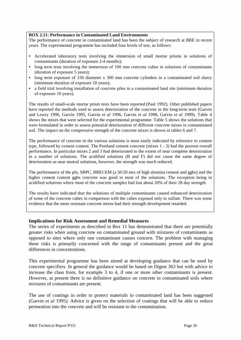
BOX 2.11: Performance in Contaminated Land Environments The performance of concrete in contaminated land has been the subject of research at BRE in recentyears. The experimental programme has included four levels of test, as follows: • Accelerated laboratory tests involving the immersion of small mortar prisms in solutions of
contaminants (duration of exposure 2-4 months);• long term tests involving the immersion of 100 mm concrete cubes in solutions of contaminants
(duration of exposure 5 years);• long term exposure of 150 diameter x 300 mm concrete cylinders in a contaminated soil slurry
(minimum duration of exposure 10 years);• a field trial involving installation of concrete piles in a contaminated land site (minimum duration
of exposure 10 years). The results of small-scale mortar prism tests have been reported (Paul 1992). Other published papershave reported the methods used to assess deterioration of the concrete in the long-term tests (Garvinand Lewry 1996, Garvin 1995, Garvin et al 1996, Garvin et al 1998, Garvin et al 1999). Table 4shows the mixes that were selected for the experimental programme. Table 5 shows the solutions thatwere formulated in order to assess potential deterioration of different concrete mixes in contaminatedsoil. The impact on the compressive strength of the concrete mixes is shown in tables 6 and 7. The performance of concrete in the various solutions is most easily indicated by reference to cementtype, followed by cement content. The Portland cement concrete (mixes 1 - 3) had the poorest overallperformance. In particular mixes 2 and 3 had deteriorated to the extent of near complete deteriorationin a number of solutions. The acidified solutions (B and F) did not cause the same degree ofdeterioration as near neutral solutions, however, the strength was much reduced. The performance of the pfa, SRPC, BRECEM (a 50:50 mix of high alumina cement and ggbs) and thehigher cement content ggbs concrete was good in most of the solutions. The exception being inacidified solutions where most of the concrete samples had lost about 20% of their 28 day strength. The results have indicated that the solutions of multiple contaminants caused enhanced deteriorationof some of the concrete cubes in comparison with the cubes exposed only to sulfate. There was someevidence that the more resistant concrete mixes had their strength development retarded.
Implications for Risk Assessment and Remedial Measures The series of experiments as described in Box 11 has demonstrated that there are potentiallygreater risks when using concrete on contaminated ground with mixtures of contaminants asopposed to sites where only one contaminant causes concern. The problem with managingthese risks is primarily concerned with the range of contaminants present and the greatdifferences in concentrations.
This experimental programme has been aimed at developing guidance that can be used byconcrete specifiers. In general the guidance would be based on Digest 363 but with advice toincrease the class from, for example 3 to 4, if one or more other contaminants is present.However, at present there is no definitive guidance on concrete in contaminated soils wheremixtures of contaminants are present.
The use of coatings in order to protect materials in contaminated land has been suggested(Garvin et al 1995). Advice is given on the selection of coatings that will be able to reducepermeation into the concrete and will be resistant to the contamination.

R&D Technical Report P331 Page 27
In general it is not considered that soil has to be excavated and removed, contained or treatedin order to overcome risks presented by contaminated land to concrete. However, soils may beremedied for other reasons such as risks to human health or water sources that would removeor reduce the risks to concrete.
2.4 Reinforced Concrete
Reinforced concrete technology is now over one hundred years old and it is used in manycountries and structures around the world (Andrioli 1998). The reinforcement is used toimprove the tensile strength of the concrete. However, there are many buildings and structuresthat have suffered damage due to corrosion of the reinforcing bars in the concrete.
Hazards Corrosion of the reinforcement can be caused by a breakdown of the protective layer, either asa result of corrosive ions, for example attack by chlorides, or as a result of a reduction in thepH of concrete through carbonation or leaching of calcium from the hardened cement paste.Further details of reinforcement corrosion in aggressive environments are given in Box 12.

R&D Technical Report P331 Page 28
BOX 2.12: Reinforced Concrete Deterioration Concrete normally provides steel with corrosion protection as the alkaline environment of hydratedcement (pH 12.6 to 13.5) leads to the formation of a protective layer at the steel/concrete interface(ACI 1985, BRE 1982a, BRE 1982b). The protective layer is generally regarded to be a tightlyadhering film of γ—Fe2O3 that forms soon after placing the concrete (Sagoe-Crentsil 1989). Thecement matrix also provides a physical barrier to the ingress of corrosion-inducing agents such asoxygen, water and chlorides. The corrosion of steel in concrete is generally regarded as an electrochemical process. The pressuregenerated by the formation of the rust, which occupies a larger volume than the iron from which itformed, can far exceed the tensile strength of the concrete with the result that the concrete cracks andeventually disintegrates. The rate of corrosion is determined by the rate of oxygen diffusion throughthe concrete that is faster in relatively dry than in saturated concrete (ACI 1985). If the pH is high andno chloride is present the ingress of oxygen does not cause corrosion. Corrosion of the steel will onlyoccur if the concrete carbonates or there is a deleterious material present. For oxygen to be consumedin the cathodic reaction it must be in the dissolved state. Therefore, the presence of water is aprerequisite for corrosion to take place. As the water content of the concrete increases then the rate ofoxygen diffusion decreases. In totally saturated concrete diffusion is too slow for corrosion to takeplace even if the passive layer at the surface of the reinforcement has been destroyed (CEB 1989).Corrosion of steel has occurred in North Sea oil rigs well below sea level. The presence of sufficient quantities of free chloride ions in the concrete can stimulate reinforcementcorrosion even in highly alkaline conditions (BRE 1982a, BRE 1982b, Nixon 1980). Threemechanisms have been postulated to explain the effect of chloride ions on steel corrosion as follows(ACI 1985, BRE 1994): • Chloride ions destroy the protective layer on the steel surface either by penetrating the film
through pores and defects or by colloidal dispersion of the film that makes it easier to penetrate.• Chloride ions are adsorbed on the metal surface, promoting the hydration of the metal ion and
thus facilitating the dissolution of metal ions.• Chloride ions react with the ferrous ions produced in an anodic reaction to form a soluble iron
chloride (green rust). This diffuses away from the anode destroying the protective layer(Raharinaivo 1987).
The ingress of chloride ions produces ‘pitting’ corrosion as the passive film is destroyed over only asmall area (CEB 1989, Arup 1983). Considerable work has been carried out on chloride-induced corrosion of steel reinforcement, inrelation to atmospheric and marine conditions (ACI 1980, CIRIA 1985/86, Page 1990), but lessattention has been paid to reinforcement corrosion in buried structures. In underground concrete the physical properties of the concrete, in particular their influence ondiffusion of oxygen and chloride, play an important role in determining the rate and extent ofcorrosion of the reinforcement (Nixon 1980). The vulnerability of reinforced concrete structures atthe soil/atmosphere interface has been shown in houses built on former salt ponds (Howell 1990).Reinforced slab foundations had been placed in direct contact with soil containing 1400 to 4300 ppmCl- and 760 to 1700 ppm SO4
2-. Cracking and spalling were detected in most cases just above thesoil/concrete interface. Asrar et al (1999) have studied the corrosion of reinforcement in concrete containing microsilica(MS). PC and SRPC concretes were manufactured with various quantities of MS. In tests thecorrosion of reinforcing bars was suppressed in the presence of MS, and the chloride ion permeabilityreduced significantly. It was suggested that MS reduces the quantity of calcium hydroxide in theconcrete and increases the CSH phase. Therefore, the concrete becomes less porous and has a lowerpermeability.
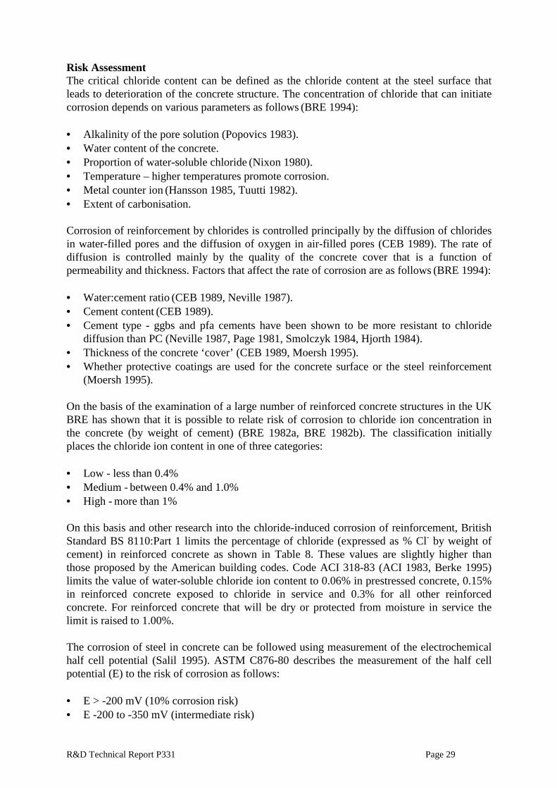
R&D Technical Report P331 Page 29
Risk Assessment The critical chloride content can be defined as the chloride content at the steel surface thatleads to deterioration of the concrete structure. The concentration of chloride that can initiatecorrosion depends on various parameters as follows (BRE 1994):
• Alkalinity of the pore solution (Popovics 1983).• Water content of the concrete.• Proportion of water-soluble chloride (Nixon 1980).• Temperature – higher temperatures promote corrosion.• Metal counter ion (Hansson 1985, Tuutti 1982).• Extent of carbonisation.
Corrosion of reinforcement by chlorides is controlled principally by the diffusion of chloridesin water-filled pores and the diffusion of oxygen in air-filled pores (CEB 1989). The rate ofdiffusion is controlled mainly by the quality of the concrete cover that is a function ofpermeability and thickness. Factors that affect the rate of corrosion are as follows (BRE 1994):
• Water:cement ratio (CEB 1989, Neville 1987).• Cement content (CEB 1989).• Cement type - ggbs and pfa cements have been shown to be more resistant to chloride
diffusion than PC (Neville 1987, Page 1981, Smolczyk 1984, Hjorth 1984).• Thickness of the concrete ‘cover’ (CEB 1989, Moersh 1995).• Whether protective coatings are used for the concrete surface or the steel reinforcement
(Moersh 1995).
On the basis of the examination of a large number of reinforced concrete structures in the UKBRE has shown that it is possible to relate risk of corrosion to chloride ion concentration inthe concrete (by weight of cement) (BRE 1982a, BRE 1982b). The classification initiallyplaces the chloride ion content in one of three categories:
• Low - less than 0.4%• Medium - between 0.4% and 1.0%• High - more than 1%
On this basis and other research into the chloride-induced corrosion of reinforcement, BritishStandard BS 8110:Part 1 limits the percentage of chloride (expressed as % Cl- by weight ofcement) in reinforced concrete as shown in Table 8. These values are slightly higher thanthose proposed by the American building codes. Code ACI 318-83 (ACI 1983, Berke 1995)limits the value of water-soluble chloride ion content to 0.06% in prestressed concrete, 0.15%in reinforced concrete exposed to chloride in service and 0.3% for all other reinforcedconcrete. For reinforced concrete that will be dry or protected from moisture in service thelimit is raised to 1.00%.
The corrosion of steel in concrete can be followed using measurement of the electrochemicalhalf cell potential (Salil 1995). ASTM C876-80 describes the measurement of the half cellpotential (E) to the risk of corrosion as follows:
• E > -200 mV (10% corrosion risk)• E -200 to -350 mV (intermediate risk)

R&D Technical Report P331 Page 30
• E < -350 mV (90% corrosion risk).
The design of reinforced concrete has to consider the whole system and not concentrate onone aspect of the material (Berke 1995). Reducing the w/c ratio or using a pozzolanic materialmay not be sufficient in aggressive environments in the long term. Indeed, some measuressuch as reducing the w/c ratio or increasing the cement content can result in increased dryingand shrinkage of the concrete and result in cracking that would lead to routes for chlorideingress.
Remedial Measures In general it would not be necessary to undertake removal, containment or treatment of soil tomanage the risks from contaminated land to reinforced concrete. It is preferable to produceconcrete that is of good quality and suitably designed to resist contaminant attack.
A number of measures can be included in the reinforced concrete with respect to reducing thepotential for reinforcement corrosion, as follows:
• Provide suitable concrete cover, of depth and density, to the reinforcement (BSI 1985);• Reduce the permeability of the cover concrete;• Protect the reinforcing bar using epoxy coatings;• Use cathodic protection in aggressive environments;• Prevent drying shrinkage and cracking of the cover concrete by the use of admixtures or
replacement materials such as ggbs.• Use corrosion inhibitors, one example is nitrite based inhibitors that are chemical
admixtures or surface applied treatments that compete with chlorides for sites on thereinforcing bars (Broomfield 1999).
The repair of damaged reinforced concrete is a specialised field, but one in which there isconsiderable experience. The most common approach to repairing damaged reinforcedconcrete is to remove the concrete to beyond the level of the reinforcement. The reinforcementcan then be cleaned and the corrosion removed, a coating can then be applied if this is thoughtto be necessary. The concrete cover can then be built up using a suitable repair concrete.
Alternative methods of repair can be considered, as follows, these depend on the condition ofthe concrete and degree of deterioration:
• Desalination and realkalisation techniques using the application of electric currentsbetween the concrete surface and the reinforcement. Chloride ions are moved outwardstowards an electrolyte membrane where they collect. The concrete cover is re-alkalisedduring the process.
• Treatment of the concrete surface can be undertaken using suitable coatings. This shouldonly be done when the surface is in good condition and the reinforcement is still covered.Coatings are therefore most likely to be used where future problems are being predicted asopposed to dealing with failure.

R&D Technical Report P331 Page 31
2.5 Asbestos Cement
Asbestos cement is a composite material in which 10 to 15% asbestos fibre is bound in amatrix of Portland Cement (PC) or autoclaved calcium silicate. Most asbestos cement is madewith white asbestos (DoE 1991).
Hazards Asbestos fibre is mechanically strong and highly resistant to heat and chemical attack (DoE1991). The durability of asbestos cement is therefore largely controlled by the chemicalresistance of the cement paste. Further details are given in Box 12.
Risk Assessment As the problem of chemical resistance of asbestos cement is essentially a problem of thechemical resistance of the cement matrix, the mechanisms by which asbestos cement corrodesare much the same as those for concrete. Guidance on the use of asbestos cement pipe is givenin British Standard BS 8010: 1985 (BSI 1988). It advises that a coated asbestos cement pipeshould be used in conditions where the pH of the groundwater is between 6 and 5.5 and thesulfate concentration (expressed as SO3) is between 2 and 5 g/l. In conditions where the pH isless than 5.5 and the SO3 level above 5 g/l the standard recommends that specialist advice besought.
BOX 2.13: Asbestos Cement Performance The acid corrosion of asbestos cement differs from concrete degradation in that asbestos cementcorrosion progresses and softens the matrix in only a thin layer, from tenths of a millimetre to a fewmillimetres deep (Nebesar 1983). The depth to which the material is softened depends on thefollowing: • The duration of the corrosive action,• The concentration of the aggressive chemical,• The convection conditions in the reaction environment,• The solubility of the corrosion products. Corrosion due to sulfates causes failure as a result of expansion leading to cracking and spalling ofthe cement surface. Asbestos cement is less permeable than most bulk concrete and therefore it isgenerally considered to be more resistant to corrosive influences. However, for certain chemicalenvironments, for example sulfates, the experimental evidence does not support this hypothesis.Investigations into the sulfate resistance of asbestos cement pipes have found that once they areexposed to an aggressive sulfate environment they perform no better than other cementitious product(Mason and Blair 1962, Maui 1985). Mason and Blair showed that the durability of asbestos cementis directly related to the free lime content of the hydrated cement paste. They submerged samples ofnormally cured asbestos cement pipe (high free lime content) and autoclave-cured asbestos cement(low free lime content) in Medicine Lake, South Dakota (35 000 ppm SO4
2-). After 10 years normallycured samples had been completely destroyed while autoclaved samples (with lower free limecontent) showed no signs of deterioration.
Remedial Measures Guidance on the durability of asbestos cement pipe has also been developed by manufacturers(Crathorne 1987 gives two references, TAC and Fibronit). Asbestos cement pipes are notrecommended for the following conditions:
R&D Technical Report P331 Page 32
• Sulfate content (expressed as SO3) of the ground-water is >5000 mg/l;• Sulfate content (expressed as SO3) of the soil is >20 000 mg/kg (2%);• Soil/ground-water pH is <5.5;• Free carbon dioxide content of the ground-water (in ppm) is 20 + 5.1 x carbonate hardness
(as ppm CaCO3).
There are no recommendations based upon removal, containment or treatment ofcontaminated soils where asbestos cement pipes are to be used. However, other methods ofisolating the pipe from contaminated soil could be considered, examples are as follows:
• Laying the pipe in a trench with clean backfill.• Routing the pipe away from the contaminated ground or area of the site with high levels of
sulfate.• Providing a sleeve or coating to the asbestos cement surface.• Laying the pipe in a clean soil cover system.
2.6 Masonry
Brickwork or blockwork is a composite of two dissimilar materials, brick or blocks andmortar. The durability of brickwork structures depends on the durability both of the masonryunits and the mortar (Grimm 1987). 2.6.1 Clay brick
Clay bricks are highly durable materials that have been used in buildings and other structuresfor centuries. Fired clay pipe material can also be considered as similarly resistant tocontaminants. However, the permeability of both bricks and clay pipes will leave them at riskfrom salt crystallisation and in the case of pipes to contamination of the contents of the pipe.
Hazards Dissolution of clay brick is potentially a serious cause of deterioration. The extent ofdissolution depends on the solubility of the glass in the material. The acid nature of the glassphase means that while it has a low solubility in a neutral or acidic environment it can have anappreciable solubility in a basic environment. The three main reaction steps in the dissolutionof the glassy matrix are as follows (BRE 1994):
• Ion-exchange reactions.• Partial hydration of the glass surface.• Dissolution of the glass surface.
Further details of clay brick deterioration are given in Box 14.
Risk Assessment Engineering bricks are well fired materials glassy materials that are durable under aggressiveunderground conditions. For example, in sewers and similar conditions they have proven to bethe most durable masonry lining.
The maximum dissolution of brick is usually only 1% except when attacked by hydrofluoric

R&D Technical Report P331 Page 33
acid, and so the extent of deterioration by dissolution is usually small.
A potentially more serious problem for brickwork is the crystallisation of soluble salts withinthe brick pore structure. The salts are transported by water to the interior of brick and canderive from the external environment or from the rehydration of the soluble phase of the brick.However, salt crystallisation is only likely to occur where there is a gradient from a wetinterior to a drying surface. The potential for salt crystallisation in the ground is therefore low.
Bricks are not generally subject to attack from fungi and bacteria.
BOX 2.14: Brick Performance Clay bricks are essentially a composite of crystalline phases embedded in a glassy matrix. Thecrystalline components are generally of low solubility, and so the corrosion properties are usuallydetermined by the glassy phase, which in some cases can constitute as much as 60% of the brick (Hill1960). A number of studies have shown that the most durable bricks are those with a low porosity andlow microporosity (Robinson 1984, Somsiri 1985, BRE 1992). British Standard BS5628: Part 3 (BSI 1985) provides an overview of the durability of masonry inaggressive conditions. The durability of masonry, both units and mortar, is described as beingaffected by the following: • Exposure to the weather or other sources of water.• Exposure to aggressive conditions from all sources including the ground.• The adequacy of measures taken to prevent the masonry from becoming saturated both in terms
of design and workmanship. Aggressive contaminants, such as sulfate, can be prevented from entering the main wall structurefrom the ground by the use of appropriate damp proof courses (BSI 1985). However, brickworkbelow the ground will still be subject to exposure to sulfates and other contaminants below the dpclevel. Calcium silicate bricks are resistant to attack by most sulfate salts in the soil and ground-water (BSI1987). The durability of calcium silicate bricks under salt crystallisation attack can be attributed to acombination of their low soluble salt content and their low porosity and coarse pore structure.However, the calcium silicate bricks may be attacked by high concentrations of magnesium andammonium sulfate. They may also suffer severe deterioration if they are impregnated by strong saltsolutions, such as calcium chloride or sodium chloride, and then subjected to frost. The resistance of buried brickwork to sulfate attack is being investigated in a long-term durabilitytrial, involving four half-brick walls built with calcium silicate bricks (Class 2-3 according to BritishStandard BS187: 1978) in 1:1:6 mortar (Saunders 1987). A visual examination of the four calciumsilicate walls after 15 years’ burial found no sign of deterioration either to the bricks or to the mortar.
Remedial Measures Soil removal, containment or treatment is not normally considered necessary in managing therisks to clay bricks in contaminated land. It is normal to ensure that the brick will not beattacked by contaminants in the ground through either dissolution or salt crystallisation.
Guidance is provided on the durability of clay bricks in aggressive environments in BS8301where it is stated that bricks are particularly suitable for soil environments containing sulfatesor acids (Carlsson 1988). BS5628: Part 3 provides guidance on masonry in aggressive

R&D Technical Report P331 Page 34
conditions. In cases where continuous exposure to foul water sources is predicted then the useof engineering bricks is recommended. 2.6.2 Concrete blocks
Hazards Precast aggregate concrete blocks and autoclaved aerated concrete (AAC) blocks arecommonly used in the construction of shallow foundations for housing and low rise buildings.Concrete blocks are potentially attacked by the same contaminants and ground conditions thataffect dense concrete. Box 15 contains details of the limited studies that have been undertakenon concrete blocks in aggressive soil conditions.
BOX 2.15: Concrete Block Performance Recent work has assessed the durability of various precast concrete blocks in sulfate solutions (Pettit1996). In this research blocks were subjected to sulfate soil conditions. It was found that the blockswere resistant to sulfate class 3 levels. This was regardless of the type of cement used in themanufacture of the blocks. It was found that there was a positive benefit from allowing the concreteblocks to carbonate prior to immersion in the aggressive solutions. This finding is in agreement withother work where the benefits of some carbonation on sulfate resistance have been found for denseconcrete (Arber 1961). BS5628: Part 3 (BSI 1985) does not allow the use of aircrete and aggregate concrete blocks to beused in foul drainage. Therefore, concrete blocks are not generally suitable for acid soil conditions. Insurface water conditions concrete blocks can be used with certain limitations. The performance of concrete blocks in contaminated soils using both laboratory and field tests is thesubject of current work at BRE.
Risk Assessment and Remedial Measures In general the mechanisms of chemical attack on concrete blocks is likely to be the same as fordense concrete. BRE Digest 363 allows the use of precast and AAC blocks in class 1conditions, and in class 2 and 3 providing the density is greater than 600 kg/m3.
It is not normally considered necessary to remove, contain or treat soil in order to managerisks to concrete blocks. However, soil may be remedied for other reasons that may help toremove or reduce the risk to the blocks. At present there would be doubts over the use ofconcrete blocks where sulfate levels exceed class 3 sulfate levels (3 g/l) and this is a barrier totheir use in developing contaminated sites. The current research on their performance incontaminated soil is therefore necessary.
Concrete blocks are not allowed in foul drainage and therefore their use in acid soils isquestionable. 2.6.3 Mortar
Mortars are based on building sands (‘soft’ sands) mixed with cement and/or lime as a binder(BRE 1991). In the UK, the most commonly used cements are Portland cements and masonrycements. Masonry cements are a mixture of Portland cement and fine mineral filler (forexample limestone) with an air-entraining agent.

R&D Technical Report P331 Page 35
Hazards Mortar is subject to the same agents of deterioration as concrete where one of the main causesof the deterioration of mortar is sulfate attack (Harding 1986). The reaction between sulfateand the hydrated tricalcium aluminate in Portland cement results in the expansive formation ofettringite. At low temperatures the deteriorated sample may also contain thaumasite (BRE1996, Crammond 1985, Halliwell and Crammond 1996). Further details are given in Box 16.
Risk Assessment Sulfates can come from the environment adjacent to the brickwork or originate from thebricks themselves. Calcium, magnesium, sodium and potassium sulfates are present in almostall fired-clay bricks. Water can dissolve a fraction of these sulfates and transport them to themortar, where they can react with the hydrated constituents of the cement binder.
BOX 2.16: Mortar Performance The durability of building mortar under sulfate attack was investigated in a series of laboratoryexperiments at BRE (Harrison 1986). The sulfate resistance of mortar was found to be improved bythe use of sulfate-resisting Portland cement and lime:Portland cement mortars with a cement contentof at least 200 kg/m3. Lime mortars were found in a recent study to be more durable to sulfate attackthan PC mortar that was used in restoration work (Moricini 1994). Halliwell and Crammond (1996) have studied the deterioration of brickwork mortar in undergroundretaining walls. Problems were experienced when the ground water conditions were changed and themasonry was subject to constant wet and cold conditions. The source of sulfate, however, was fromthe type of brick that was used. Whilst the sulfate was in the form of calcium sulfate when it was wetfor a long period of time the sulfates transferred to the mortar joint. The 1:3-5 PC:sand mortar,although strong, was rapidly affected by thaumasite attack. Microbially induced corrosion is recognised as being important to the performance of PC and limemortars (Wilimzig 1996a, Wilimzig 1996b). Some bacteria can oxidise ammonia to the inorganicacids (nitrous and nitric acids). Mortar located in wet areas can contain high amounts of bacteria andfungi, as water is one of the main causes of growth of micro-organisms. Ammonia from theenvironment has been found to convert to nitrites and nitrates and then to nitric acid. This was thenfound to cause damage to mortar in buildings.
Remedial Measures Guidance on suitable mortar designations for a number of environments is given inBS5628:Part 3 (BSI 1985). However, there are no specific guidelines for contaminatedground. BRE Digest 363 gives recommendations for both the composition and use of ageneral use mortar (lime:Portland cement) and sulfate resisting Portland cement that haveresistance to attack by sulfates.
In general soils are not removed, contained or treated in order to manage the risks to mortarfrom contaminated soil.
2.7 Metals
There are a number of metals that are used in building either for piles, services, non-structuralcomponents and structural components. The most common types of metals used are steel,stainless steel, copper, lead, zinc, aluminium and cast iron. All these metals can deterioratethrough corrosion processes and the mechanisms and types of corrosion are common to allmetals.

R&D Technical Report P331 Page 36
2.7.1 Corrosion
Mechanisms of Corrosion The common forms of corrosion are as follows (BRE 1994):
• Electrochemical – the most common form of corrosion in an aqueous medium.• Chemical corrosion - occurs when there is direct charge transfer between the metal and the
attacking medium. Examples of chemical corrosion are oxidation, attack by acids andalkalis, and the action of organic solvents.
• Microbial induced corrosion (Tiller 1984, Von Wolzongen Kultr 1934, Shrier 1976, Zhu1995).
Forms of corrosion Corrosion can affect metals in a variety of ways depending on the nature of the metal and theprecise environmental conditions to which it is subjected (Carlsson 1988). The main forms ofcorrosion are as follows (BRE 1994, Davies 1996, Fontana 1983, Shrier 1976).
• Uniform corrosion is usually characterised by chemical and electrochemical reactions thatcorrode the metal evenly over the majority of its surface. This is the most common form ofcorrosion.
• Localised corrosion is caused by heterogeneities in the metal. The environment orgeometry of the structure can cause certain areas of the metal surface to corrode at a higherrate than others. Forms of localised corrosion include crevice corrosion, intergranularcorrosion or stray current corrosion.
• Pitting is an extreme form of localised attack that results in small holes (pits) thatpenetrate the metal and cause perforation.
• Selective dissolution occurs in some alloys where one component, usually the most active,is selectively removed.
The synergistic action of corrosion and mechanical actions can result in localised attack orfracture of the metal. The most common forms of combined chemical and mechanical attackare stress corrosion cracking and hydrogen embrittlement. Risk Assessment and Remedial Measures for Corrosion Corrosion in soil is predominantly an aqueous electrochemical process. However, conditionsin soil vary from dry to saturated and, as a result, corrosion can range from negligible to rapid(Davies 1996, Hassani 1978, Lankes 1981). Variations in soil composition or structure cancause different environments to act on different parts of the same metal element that results indifferent electrical potentials at the soil-metal interface.
The heterogeneous nature of soil and the variety of factors that contribute to the operation ofthe corrosion cell make soil corrosivity difficult to predict. However, examination of theelectrochemical mechanism shows that the conductivity of soil can be rate-controlling and, asa result (see Table 10), soil resistivity measurements have become one of the most widelyused measurements of soil corrosivity (Uhlig 1971, King 1977, Knofel 1978, Miller 1981).
Booth et al (1971) developed a classification of soil corrosivity using resistivity and redoxpotential measurements. In cases where the two measurements placed the soil on theborderline between corrosive and non-corrosive, the classification used water content as afurther criterion of corrosivity. If the water content of the soil was greater than 20% then the

R&D Technical Report P331 Page 37
soil was regarded as corrosive.
A number of other classifications have considered the combined effect of resistivity, redoxpotential, moisture content, pH, presence of carbonaceous materials, chlorides, sulfates,sulfides and carbonates. The most comprehensive of these ‘complete’ classifications are thosedevised by the German Gas and Water Association (DVGW) and the Ductile Iron PipeResearch Association (DIPRA) to measure the corrosivity of soil towards iron and steel(Collins 1983). 2.7.2 Cast Iron
Cast iron is a term used to describe ferrous metal alloys containing more than 1.7% carbon. Itis comparatively cheap and easy to manufacture and therefore has been extensively used in themanufacture of pipes (Collins 1983). The main types of cast iron commonly encountered are‘grey’ cast iron, in which most of the carbon is in the form of carbon flakes, and ductile castiron, which uses graphite nodules.
Hazards Traditionally, cast iron is regarded as having good resistance to corrosion by soils, theprincipal hazard being mechanical overloading (Collins 1983). More details are given in Box17. However, corrosion can occur through the development of large-scale galvanic cells,caused by differences in salt concentrations, oxygen availability or the presence of strayelectrical currents (Davies 1996).
Cast iron possesses no useful resistance to mineral acids. Hydrochloric acid will causecorrosion at any concentration and temperature. Dilute sulfuric, nitric and phosphoric acids arealso aggressive. Similarly corrosive are well-aerated organic acids.
Risk Assessment The corrosivity of salt solutions depends on the nature of the ions present. Salts of aluminium,iron and calcium hydrolyse to give acid solutions that if well aerated are corrosive to cast iron.
BOX 2.17: Cast Iron Performance The resistance of cast iron pipes, both grey and ductile iron, to soil corrosion was comprehensivelyinvestigated in a nine-year study carried out jointly in the UK (Colchester), Germany (Varel), andFrance (Mont St Michel). More than 1000 specimens were buried in the three countries andexcavated at two, five and nine years for examination. The characteristics of the three sites are givenin Table 11. A comparison of the maximum pitting depths found that the samples buried in soils containingappreciable quantities of chloride and sulfate (Varel and Mont St Michel) had corroded to a greaterextent than those buried in soils containing only a small amount of the anions (Colchester). Theresults also showed that ductile cast iron had superior corrosion resistance to grey cast iron.
Cast iron is susceptible to corrosion by sulfate-reducing bacteria. In addition to localisedpitting corrosion it undergoes a form of selective leaching known as graphitisation thatreduces the mechanical strength of the material. Failure of cast iron pipes (6 mm thick) withina year and perforation within four years as a result of microbial corrosion are quite common(Tiller 1988). The intrinsic corrosivity of the sulfide films which can develop on ferrousmetals is high (Table 12).

R&D Technical Report P331 Page 38
Remedial Measures Guidance is available on the aggressiveness of soils based on resistivity and redox potentialmeasurements. This could be developed into a series of recommendations for protection ofcast iron components using coatings, burial trenches or isolation techniques. However, atpresent there is no definitive guidance and consultants will be required to develop their ownspecification for protection of such materials.
Guidelines, drawn up by the Water Research Centre (WRc) on the use of ductile iron pipes,state that highly acid soils (pH <5) are corrosive towards cast iron pipes even when they areprotected by a system of zinc coating and loose polyethylene sleeving (Crathorne 1987, BRE1994). The WRc guidance on the use of ductile iron pipes states that groundwater containing>300 ppm chloride may corrode even protected cast iron pipes.
It is normally necessary to isolate cast iron pipes from contaminated soils. Remedial measurescould involve one or more of the following processes:
• Laying the pipe in a trench with clean backfill.• Routing the pipe away from the contaminated ground.• Providing a sleeve or coating to the pipe surface.• Laying the pipe in a layer of clean soil cover system. 2.7.3 Steel piles
Hazards The corrosion of steel requires the presence of both oxygen and water (except in the specialcase of anaerobic bacterial corrosion). In undisturbed natural soils the type and amount ofcorrosion of driven steel piles is generally so small that it is negligible irrespective of the soilresistivity and soil pH (Romanoff 1962). However, in disturbed soils corrosion rates can behigh, see Box 18. This difference in the corrosion rate of steel in disturbed and undisturbedsoil is thought to be due entirely to the differences in oxygen concentration.
BOX 2.18: Steel Pile Performance The British Steel Corporation (Morley 1978) investigated piling recovered from undergroundexposure, and confirmed the findings of a previous United States study. Corrosion of steel piling inUK soils was found to range from 0.0 to 0.03 mm/year with a mean of 0.01 mm/year. Piles in fill materials have been found to corrode at twice the rate of those in undisturbed natural soils(0.02 to 0.04 mm/year, with some piles showing corrosion rates as high as 0.06 mm/year) (Morley1988). The formation of a galvanic corrosion cell between the upper portion of the pile in the fill andlower portion in the undisturbed soil is thought to be responsible for the additional corrosion. Theheterogeneous nature of most contaminated land sites may well encourage the formation of suchcorrosion cells, and so cause an increase in the rate of corrosion of steel piling.
Steel, like cast iron, is susceptible to corrosion caused by the action of sulphur-reducingbacteria. However, there is no evidence in the literature to suggest that this is a problem withdriven steel piles, except where they project above ground in installations (Morley 1978). Onepossible explanation for the lack of microbial corrosion on driven steel piles is that inundisturbed ground, bacterial mobility, nutrient replenishment and the symbiotic relationshipwith aerobic bacteria cannot be sustained at a significant level (Morley 1988).

R&D Technical Report P331 Page 39
Risk Assessment Guidance on the use of steel piles in different environments is provided in British Steels PilingHandbook (British Steel 1997). This covers underground conditions where the lack ofcorrosion of steel piles driven into undisturbed soils has been noted. A maximum corrosionrate of 0.015 mm/side of the pile is allowable each year. In the case of landfill sites orindustrially contaminated soils corrosion rates may be higher and additional protection will berequired for the steel pile. The effective life of unprotected steel piling depends upon thecombined effects of imposed stresses and corrosion rates. The end of the effective life isreached when any part of the pile reaches the maximum permissible working stress as a resultof the loss of section due to corrosion. Guidance is provided in the Piling Handbook on howto calculate the effective life of steel piling in various environments. However, there is nospecific guidance for contaminated soils.
Remedial Measures Remediation of contaminated soil by removal, containment or treatment is not normallyconsidered solely in order to protect steel piles. In cases where there are concerns overdurability it may be preferable to use a more resistant type of steel or consider alternativetypes of piles. The use of coatings for steel has been suggested as a way of providingadditional protection for aggressive soils (BRE1995). However, experience has shown somecoatings can be severely damaged when piles are driven into made ground that contains hardmaterials such as waste brick or concrete or stone.
In aggressive environments, such as marine exposure or contaminated ground, it is necessaryto provide additional protection to steel. This can be done in various ways as follows:
• The use of zinc or zinc/alloy coating systems (including Zn/Al, Zn/Fe, Zn/Ni, Zn/Co,Zn/Cr).
• The use of a conversion coating.• The use of an organic coating applied by painting of liquid paint, or stoving of powder
coatings. Polyester and epoxy powder coatings are commonly used.• Cathodic protection systems. 2.7.4 Stainless Steel
Hazards Stainless steel is used in buildings in a number of applications, including services, pipework,reinforcement bars for concrete and wall ties. There has been a general shift in recent yearsfrom copper pipes to stainless steel, as they can cope with a wider range of water qualities andconditions (Powell 1996). However, there is little knowledge of their performance in the longterm and in aggressive environments. Box 19 provides more information on stainless steel.

R&D Technical Report P331 Page 40
BOX 2.19: Stainless Steel Performance Stainless steel is an alloy of iron with chromium, nickel, zinc or molybdenum. There are varioustypes of stainless steel that are described as Types 304, 304L, 316 and 316L. Type 304 is generallythe most widely used, but type 316 that contains molybdenum is more resistant (Percival 1998).Stainless steel forms a durable layer of chromium oxide almost instantaneously on exposure to air andwater. However, weaknesses in the film will be exposed by aggressive environments. Atmospheric corrosion of stainless steel has been studied in roof and eaves situations (Tochihara1996). It was found that chloride was the main factor that facilitated corrosion. In general the eaveswere worse than the roof as they were not subject to washing from rainwater that removed salts.
Risk Assessment Stainless steel can withstand pH of 6.5 to 8.5, but aggressivity of soil also depends on chloridecontent. At concentrations of chloride of less than 200 mg/l type 304 stainless steel can beused. However, for chloride concentrations of 200 to 1000 mg/l then type 316 should be usedin preference to type 304 and above 1000 mg/l type 316 should always be used (Powell 1998).
Remedial Measures Remediation of contaminated soil by removal, containment or treatment is not normallyconsidered solely in order to protect stainless steel. Specific guidance is not available on thespecification and protection of materials in contaminated land. However, the evidencepresented above shows that 316 grades of stainless steel should be used in aggressiveenvironments. 2.7.5 Galvanised steel
Hazards Zinc galvanising of steel is in itself a way of protecting the steel from atmospheric corrosionand from aggressive environments. However, zinc galvanising can be corroded by salts andacids.
Risk Assessment Galvanised steel is used in structural steelwork, cold rolled sections, decking, cladding, rebars,wall ties, fasteners and services. A study has been undertaken to assess the performance ofgalvanised steelwork in various aggressive environments in construction (Dennis 1997).Samples of steel with zinc and zinc alloys were immersed in various solutions. Zinc alloysgenerally performed better than pure zinc coatings. Chromate conversion coatings alsoenhanced the performance of all the coatings examined.
Remedial Measures Remediation of contaminated soil by removal, containment or treatment is not normallyconsidered solely in order to protect galvanised steel. However, there is currently no guidanceon the use of galvanised steel in contaminated ground. 2.7.6 Copper
Hazards Copper is commonly used in pipes for gas and water supplies. Copper is essentially immuneto corrosion in most natural ground environments, but in contaminated ground could besubject to corrosion by acids, sulfates, chlorides and ground containing cinders. Copper

R&D Technical Report P331 Page 41
performance in aggressive soils is detailed in Box 20.
BOX 2.20: Copper Performance Research by the British Non-Ferrous Metals Research Association (BNFMRA) between the early1940s and the late 1950s found that copper could safely be used in a wide range of soils withoutcorrosion (Davies 1996). Copper, when it does corrode, generally does so in a uniform manner.Pitting corrosion is less likely to be found and only under limited and rare conditions (Wagner 1997,Anon 1998). Corrosion of copper pipe has been found in the following instances: • Corrosion has been found in copper pipes installed in ground containing cinders (pH 7.1) and in
highly aggressive soils, including wet acid peat (pH 4.6) and moist acid clay (pH 4.2).• Copper has been found to be rapidly attacked by oxidising acids such as nitric acid and
concentrated sulfuric acid, acid solutions containing oxidising agents such as ferric and stannicions, and strongly oxidising alkaline solutions (Crathorne 1987, Davies 1996).
• Salts of sulfate and chloride have been strongly linked to copper corrosion, particularly whenfound in soils with poor drainage and high moisture retention capacity (Myers 1984). Cyanidescan also attack copper pipes through the formation of complexes with copper (Davies 1996).
• In soils containing sulfate-reducing bacteria (srb), where anaerobic conditions develop, sulfidescan be formed, and these are aggressive to copper. A European funded research project hasrecently been studying microbially induced corrosion of copper (Wagner D 1997). It was foundthat the basic corrosion process appears to follow the chloride model, but this can becomeovershadowed by the effects of additional anions such as sulfate and bicarbonate.
• Severe corrosion of copper pipe has also resulted from the formation of differential aeration cells(Anon 1998). A 6 m copper pipe, of which 4 m was in sand and 2 m in clay, corroded through inless than six months.
• Corrosion of copper pipes was caused by cinders, acid peaty soil, sulfate reducing bacteria, andthe presence of deleterious chemicals in the soil. There is, however, no direct relationshipbetween any single feature of soil composition or constitution and the rate of corrosion.
Risk Assessment The resistance of copper to corrosion is due to the formation of a protective oxide film, Cu2O,that covers the entire surface of the metal. In atmospheric corrosion the green patina whichprovides protection is initially CuSO4.Cu(OH)2 and changes in time to CaSO4.3Cu(OH)2. Ifthis film is destroyed and cannot be replaced, then copper will corrode. In most soil conditionsthe film remains intact or is readily repaired, and so corrosion is limited (Myers 1984).
Remedial Measures Remediation of contaminated soil by removal, containment or treatment is not normallyconsidered solely in order to protect copper pipes. There is no guidance on specific issues ofthe durability and protection of copper in contaminated land. However, copper is resistant innatural soils and to a number of contaminants that are likely to be found in the ground.Protection of copper pipes could be achieved through the following:
• Laying the pipe in a trench with clean backfill.• Routing the pipe away from the contaminated ground.• Providing a sleeve or coating to the pipe surface.• Laying the pipe in a clean soil cover system.

R&D Technical Report P331 Page 42
2.7.7 Lead
Hazards Lead has been used in construction in various applications such as pipes, flashings, dampproof courses, tanking and roof sheets. Lead pipes are no longer used, although many may stillbe found in buildings. Lead has been found to be subject to corrosion from acids inconstruction, especially in lead roofs (LSA 1990).
Risk Assessment Lead is a durable material that is resistant to corrosion in most environments. There are noparticular concerns over lead sheets used in urban, rural or coastal environments and even thinsheets will last the lifetime of a building. However, other factors such a thermal movementcan lead to breakdown of the material. Slow corrosion of lead has been noted by the release ofdilute acids from lichen and mould growth.
Lead sheets are protected by a patina which forms on contact with air which are composed ofcerrusite (PbCO3) or hydrocerrusite (Pb2(CO3)2(OH2))
(Edwards 1997). In some cases thispatination is undesirable as it is aesthetically unacceptable. A coat of patination oil should beused to protect the lead if it is exposed to air and water. The formation of lead sulfate on thesurface of lead prevents further corrosion as it is insoluble. For this reason sulfuric acid ismanufactured in a lead retort.
Organic acids from timber in the roof can leach out and caused deterioration of the leadsheets. Lead damp proof courses can be subject to attack from free lime released by Portlandcement based mortar and concrete. In the presence of moisture a slow corrosive attack isinitiated on the lead sheet. It is recommended that a thick coat of bitumen coating should beused to protect the lead damp proof course.
Remedial Measures Remediation of contaminated soil by removal, containment or treatment is not normallyconsidered solely in order to protect lead components. There is no guidance that is currentlyavailable on lead in contaminated soils. However, the literature has shown that acids andalkalis (lime) could be aggressive towards lead and clearly protection would be required wherethese conditions exist.
2.8 Organic Materials 2.8.1 Plastics
The range of plastics used in construction is wide and increasing. The principal uses ofplastics below ground are shown in Table 13. The deterioration of plastics varies with theindividual material (chemical and morphological structure, and the type and content of anyadditive) and with the environment in which it is exposed. In general, plastics deterioratethrough degradation of their polymeric constituent. However, loss of plasticiser and otheradditives can render plastics ultimately unserviceable.
The main mechanisms of polymer degradation are fully described in BRE Report BR 255 and

R&D Technical Report P331 Page 43
are summarised as follows (BRE 1994):
• Polymer degradation - This is a collective term given to the various processes that changethe physical properties and characteristics of polymeric materials (Crarthorne 1987,Schnabel 1981, Kelen 1983).
• Solvation (swelling and dissolution) - Diffusion of solvent molecules into a polymerresults in swelling of the plastic (Matrecon Inc. 1988).
• Environmental stress cracking (ESC) – This is craze or crack growth, brought about by thesimultaneous action of surface-active substances (for example alcohol, soap, wettingagent) and mechanical stress (Crathorne 1987).
• Microbial degradation (biodegradation) - This is essentially a chemical process, involvingextracellular enzymes produced by bacteria (Huang 1990). Fungi can also cause crackingand crazing of some plastics (Seal 1988).
Sunlight, heat, moisture and certain chemical agents are the main environmental factors thataffect the durability of plastics (BRE 1977). The susceptibility of polymers used ingeosynthetics to aggressive soils is shown in Table 14.
Permeation is the transport of compounds through plastic without necessarily causing theplastic to fail mechanically (BRE 1994). The driving force for permeation is the difference inconcentration of a contaminant on the upstream and downstream sides of the plastic.Permeation through plastics proceeds in three phases (Matercon Inc 1988):
• Organic chemicals accumulate in the soil/plastic interface, either by going into solution orby adsorption of the permeant at the surface of the plastic,
• The organic chemicals diffuse through the plastic,• There is partition between the organic chemicals in the plastic and in the water contained
by the plastic, i.e. evaporation or desorption of the permeant occurs at the downstream sideof the plastic.
However, the precise mechanism by which an organic chemical permeates a plastic differswith the type and form of polymer (Vonk 1985). 2.8.2 Plastic Membranes and Geotextiles
Plastic membranes and textiles are used in construction as damp proof courses, gas resistantmembranes for buildings, cover systems and liners. They are required to restrict the movementof water or gas from the ground into the building, building materials or components. Thecommon materials used for membranes are polyethylene and poly vinyl chloride.
Hazards Membranes of polyethylene and PVC are attacked by a variety of acids and solvents. Boxes 21and 22 provide details of the performance of polyethylene and PVC in aggressiveenvironments.

R&D Technical Report P331 Page 44
BOX 2.21: Polyethylene Membrane Performance The chemical resistance of high-density polyethylene (HDPE) has been investigated by Bellen, Corryand Thomas (Bellen 1987). The HDPE membrane was immersed at 230C and 500C in twenty differentchemical solutions and liquids for up to 2 years. The chemical resistance was then assessed bymeasuring changes in appearance, weight, dimensions and tensile properties. The results are shown inTable 15 where generally the properties were little affected, except by one type of lubricating oil. Further studies of the effect of waste liquids and acids on HDPE membrane have concluded that therewas little change in properties after long immersion times (Matrecon Inc. 1988, Billing 1990). High molecular weight polyethylene is resistant to microbial degradation (Kelen 1983, Seal 1988). Anumber of soil burial tests have shown that the maximum weight loss that can be expected for a highmolecular weight polyethylene due to microbial degradation is 1 to 3% (Seal 1988). Polyethylene membranes and geotextiles have also been shown to be resistant to installation damage(Greenwood 1992, Watts 1990). Damage trials with crushed limestone fill found that even under themost severe compaction regime employed in the tests the polyethylene geogrid suffered only a 13%decrease in tensile strength. Compounds of high polarity have extremely low permeability coefficients and polyethylene isessentially impermeable to them. However, a number of compounds have been shown to permeatepolyethylene in laboratory experiments. Table 16 gives an indication of the permeation behaviour of avariety of chemicals. Polyethylene is readily permeated by low molecular weight compounds such asbenzene, toluene and tetrachloroethane (Vonk 1985). More polar compounds such as phenols,aliphatic alcohols and ketones, permeate polyethylene to a lesser extent. Risk Assessment Polyethylene has poor corrosion resistance to oxidising acids (nitric and sulfuric) at highconcentrations. Hydrochloric acid (HCl) does not chemically attack polyethylene but can havea detrimental effect on the mechanical properties of the polymer. HCl can easily diffuse intothe polymer, where it disrupts the intermolecular forces between the polymer chains (Bellen1987). Alkalis, basic salts, ammonia solutions and bleaching chemicals such as chlorine, willall cause deterioration in polyethylene due to environmental stress cracking (ESC).Polyethylene is resistant to non-oxidising salt solutions. However, the presence of oxidisingsalts may result in surface degradation as the ions in the salt solution have a low rate ofdiffusion in polyethylene. Organic compounds, though they do not react with polyethylene,may cause swelling or ESC to occur.
Polyvinyl chloride (PVC) is degraded by the action of oxidising acids. Nitric acid isparticularly aggressive towards PVC, causing the surface to become brittle (Bergman 1985).PVC does not deteriorate under the action of neutral and alkaline solutions. The presence ofoxidising salts may cause deterioration, but in most cases this is not a problem, as the rate ofdeterioration is slow. Remedial Measures There is no guidance in the literature that is based on quantitative assessment of the risk topolyethylene and PVC. There is a lot of general advice on how contaminants will react withthese plastics. However, there is no indication of how the ground conditions will alter thesusceptibility to certain types of chemicals.

R&D Technical Report P331 Page 45
In general, the more concentrated the contamination then the greater is the risk to plasticmembranes. The nature of the soil must be taken into account in assessing the risk, forexample, soils have been shown to sorb organic chemicals, decreasing their mobility andactivity (Holsen 1991). The amount of organic chemical sorbed by a water-saturated soildepends on the organic carbon content of the soil, the mass of the soil, the mass of water, andthe mass and type of the organic compound. BOX 2.22: PVC Membrane Performance The chemical resistance of plasticised PVC geomembrane exposed to various chemical solutions isshown in Table 17. Bellen (1987) found that the dimensional and tensile properties of PVC werelargely unaffected by water, sodium chloride and potassium dichromate solutions. However, someoils, acids and organic substances caused large changes in weight and tensile strength. The chemical compatibility of three PVC geomembranes with various waste liquids has beeninvestigated in a series of exposure tests (Matrecon Inc. 1988). The three PVC membranes differedconsiderably in their response to the different wastes. All three PVCs lost weight in ‘slop water’ (analkaline waste), brine waste and ‘oil pond waste’. The resistance of PVC towards hydrocarbons is generally as good as, or better than, that ofpolyethylene. Organic compounds such as chlorinated hydrocarbons, anilines, ketones andnitrobenzenes cause PVC to swell and eventually to dissolve (Vonk 1985). Chemicals that do notcause PVC to soften do not permeate PVC. Thus, no significant permeation occurs for alcohols,organic acids or aliphatic hydrocarbons. The chemical resistance of plasticised PVC is greatlyinfluenced by the chemical resistance of the plasticiser, which can constitute up to 40% of the plastic.Acids, alkalis and hydrocarbons can cause the plasticiser to deteriorate, and this in turn makes thePVC brittle. The permeation of polyvinyl chloride (PVC) depends on the ability of the permeant to swell thepolymer, and on its activity. The greater the ability of the permeant to swell the polymer, the lowerthe activity required to initiate permeation. Compounds that do not soften PVC do not permeate it toany significant degree (Vonk 1987). Thus, PVC is essentially impermeable to alcohols, aliphatichydrocarbons and organic acids. Plasticised PVC is highly susceptible to microbial degradation. The extent to which it is degradeddepends on the type and quantity of any additives (Kelen 1983). Bright (1992) mentions De Coste’ssoil burial tests on PVC plasticised with phthalate-based plasticisers, which found that after 4 yearsthe samples had suffered a 4 to 8% weight loss in plasticiser. This loss made the samples more brittle,with higher tensile strengths and net lower elongations.
2.8.3 Plastic pipes
Hazards Plastic pipes are predominantly manufactured from PVC and PE, but other materials can beused. In general they perform well, but it is known that chemical attack and permeation ofcontaminants through the pipes can result from use in contaminated land, Box 23 providesfurther detail on pipe performance.

R&D Technical Report P331 Page 46
BOX 2.23: Plastic Pipe Performance A review of plastic pipes and their properties for pipeline use has covered five types of material thatcould be used (Raman 1994). The description and various properties of the plastics can besummarised as follows: • Polyethylene (PE) – This is an ultra high molecular weight material, it is highly impermeable and
has good resistance to solvents, alkalis and acids. It retains good properties over a widetemperature range and has good abrasion resistance.
• Polyvinyl chloride (PVC) – The most common type of thermoplastic material used in pipelineconstruction. It is of relatively low cost, but has good physical properties and resistance tocorrosion and chemical attack. PVC tends to be attacked by solvents such as ketones, chlorinatedhydrocarbons and aromatics. It is generally used at ambient temperature.
• Polypropylene (PP) – This is this lightest of the industrial grade plastics. It has excellent strengthto weight ratio and is used at high temperatures. It is chemically resistant to acids, alkalis andorganic solvents. However, it is not recommended for use with strong oxidising acids, chlorinatedhydrocarbons or aromatics.
• Polyvinylidene fluoride (PVDF) – PVDF is a strong, tough and abrasion resistant material. It canbe used over a wide range of temperatures from –40°C to 300°C. PVDF is inert to most solvents,acids and alkalis as well as chlorine, bromine and other halogens. It is reported as having goodageing and leaching performance and can withstand bacteria.
• Polytetrafluorethylene (PTFE) – This material, otherwise known as Teflon, is one of the mostinert of the thermoplastics available. PTFE retains good mechanical properties to hightemperatures. It has good chemical resistance to solvents, acids and alkalis. However, it haspoorer tensile strength and creep resistance.
The chemical resistance of these various pipe materials has been tested in the laboratory over a rangeof temperatures; the results are given in table 19. The resistance generally reduces as the temperatureincreases. PTFE is seen to be the most resistant material, but high costs prevent its widespread use. A review of the potential for damage to plastic drainage pipes from petroleum fuel spills has beenundertaken at BRE (1997). Whilst the potential for permeation of the pipes was recognised, it wasconsidered that structural damage to polyethylene and polypropylene pipes was unlikely to occur. A survey by the Water Research Centre in the UK on the effect of contaminated land on thedistribution system in the UK found that of the reported incidents of permeation (more than 25) onlytwo involved PVC (Crathorne 1987). Both these reported incidents involved gross contamination,arising from the spillage of aviation fuel in one case and a leak of sump fuel in the other. A review of permeation of plastic pipes used for the distribution of potable water in the United States(Holsen 1990, Holsen 1991) found that the majority of permeation incidents (89%) were caused bypetroleum products. Most of the incidents were associated with gross contamination resulting fromspills or leaks, i.e. free product and not aqueous solutions. In 95% of the permeation incidents the soilcontamination occurred after pipe installation. A survey by the Water Research Centre on the effectof contaminated land on the distribution system found a similar situation in the UK (Crathorne 1987).The large majority of incidents involved contamination resulting from the spillage of petrol or otherpetroleum products such as heating oil.
Risk Assessment and Remedial Measures Plastic pipe performance in contaminated land has been the subject of a report from the WRc(Stephens 1994). This report describes three types of site from high to low risk, A = High risksite, B = Suspect site, C = Low risk site. A flow chart was developed to assess the correct

R&D Technical Report P331 Page 47
choice of pipeline material and any necessary protection, see Figure 2. It can be seen that thechoice of pipe material is made on the basis of the type of contamination present which iseither organic, inorganic or mixed contamination. The basis of this report is that organicchemicals are more likely to attack plastic pipes and therefore metal pipes are preferred inthese conditions. Conversely, inorganic contaminants are more likely to attack metal orcement based pipes. However, no single pipeline material is immune from all contaminants. Incases where no measures are taken to remove or treat contamination then there is the need forspecial precautions such as ensuring pipeline material is resistant and good pipe layingpractice is followed. Table 20 describes examples of each type of site used in the rankingprocedure.
The WRc report has extracted data from the ICRCL lists in order to provide an assessment ofwhere there could be a risk to the use of plastic pipes in contaminated ground (DoE 1987).However, the report recognised that this data had been developed for the purposes of humanhealth risk assessment and therefore, its use in assessing whether there is a risk to plasticdrinking water pipes is limited.
This report indicated that permeation of plastic pipes by organic solvents and substances was amajor problem. Data has been produced where there could be a risk to permeation of pipesthat carry drinking water. The data as presented in the report is reproduced in Table 21, andhad been adapted from a report by Wilson and Norris (Wilson 1992). It is unclear how thisdata has been derived and thus its usefulness is in some doubt. However, given the lack ofquantitative data that is available even an empirical guide based on best estimates or educatedguesses is a valuable assistance to the specifier.
Additional protection can be given to the pipeline by the following (Stephens 1994):
• Divert the pipeline route to avoid the contaminated area.• Remove contaminated soil from the site.• Protect the pipeline in the trench – e.g. isolate the pipeline in the trench, line the trench,
use impermeable and inert backfill material, use protective sleeves, use trench drains orinstall non-return valves.
• Install the pipe above the contaminated ground in a clean cover system of sufficient depth.
In cases where water supply pipelines are laid directly into contaminated soil then it isnecessary to check that the water flowing through the pipe has not become contaminated.Such checks should be carried out by sampling and analysing water from the pipe at variousintervals. As described above plastics are potentially subject to permeation by variouscontaminants. The rate of permeation through a pipe wall depends (non-linearly) on itsthickness. Small diameter pipes with thinner walls will be more affected than larger diameterpipes for a given pressure rating. 2.8.4 Electrical Cables
Hazards Electrical cables are generally protected by plastic sleeves. These sleeves are potentiallysubject to chemical attack and permeation in similar modes as plastic pipes (RAPRA 1971,Billing 1998)). Medium and low voltage cables are often laid directly into the ground and arethus at risk of attack by contaminants. High voltage cables tend to be protected directly fromthe ground as they are buried in clean backfill. The following hazards were thus identified as

R&D Technical Report P331 Page 48
important to the use of electrical cables in contaminated land:
• Degradation of the cable sheathing leading to deformation or permeation.• Swelling of plastic sheathing leading to deformation or permeation.• Ignition of combustible materials in the soil due to temperature rises in the soil induced by
cable heating.• Mechanical damage caused by large, sharp or heavy objects in the soil.• Ageing or softening of cable insulation due to high temperatures in the soil.• Transport of contaminants, in particular landfill gas, along the cable routes.
Remedial Measures The selection of appropriate cable sheathing material is obviously important to the properfunctioning of the cable over time. However, other factors such as the possibility ofunderground fires could affect the function of the cable. A number of precautions have beenproposed for the installation of electrical cables, as follows:
• Route the cable through a clean area, although this may not always be possible and there isthe potential for contaminant migration to the clean area.
• Enclose the cable in a clean fill material, possibly enclosing the backfill itself in ageomembrane.
• Treat or contain the contaminated soil in order to remove the hazard or prevent movementof the contamination to the cables.
• Provide over-sheaths to the cable, these could either be metallic such as lead or polymericmaterials.
• Lay the cables in a clean cover system above the contaminated ground.
The performance of various polymeric cable sheathing materials subjected to acids, organicsand oils is given in Table 22. 2.8.5 Rubbers
Rubbers are crosslinked polymeric materials containing a number of additives such as carbonblack, fillers, antioxidant and vulcanising agents. The corrosion resistance of rubber isdetermined by its polymeric constituent (Heap 1968). They are used in membranes and dampproof courses.
Hazards The mechanism by which rubbers deteriorate when placed in aggressive chemicalenvironments are similar to those described for plastics. Box 24 contains further details on theperformance of rubbers in contaminated soils.
Risk Assessment Oxidation is the principal form of degradation, leading to hardening and cracking of rubber.Thus, while rubbers are resistant to strong acids and alkalis, they are rapidly attacked byoxidising acids such as nitric acid and oxidising salts of metals such as copper, manganese andiron (RAPRA 1971).
Rubber is susceptible to attack by certain hydrocarbons and oils. The absorption of theseorganic liquids causes the rubber to swell. As rubber contains an appreciable amount of

R&D Technical Report P331 Page 49
crosslinking, the mechanism of swelling is similar to that of polyethylene. Swelling causesdeterioration of tensile properties as well as softening (Bergman 1985). The resistance toswelling of a number of rubbers in different liquids is shown in Table 24.
BOX 2.24: Rubber Performance The susceptibility of natural rubber to microbial degradation has been known for more than 90 years.In 1950 a series of papers reported that underground cables made from rubber had deteriorated as aresult of microbial attack. This attack was described as visible pitting and micro-porosity. Seal (1988)describes more recent soil burial tests by Williams, which have confirmed that natural rubber (crepeand smoked latex sheet) can support microbial growth and can be oxidised in the presence of micro-organisms. Vulcanisation improves the resistance of natural rubber to microbial attack. However, theincorporation of sulphur into the rubber during this process makes it vulnerable to attack by sulphur-oxidising bacteria. Heap and Morrell (1968) discuss a 1945 report by Thaysen in which attack on thesulphur in vulcanised rubber was said to be responsible for the deterioration of fire hoses that had notbeen dried thoroughly before storage. Synthetic rubbers are more resistant to microbial attack than natural rubbers. Of the types of rubbermost commonly used in water pipelines in the UK, styrene-butadiene rubber (SBR), ethylene-propylenediene (EPDM) and acrylonitrile-butadiene (NBR), SBR is the most susceptible to microbialattack. The biodegradation of SBR is thought to be due to preferential attack on the compoundingingredients rather than degradation of the styrene-butadiene copolymer. The presence of lowmolecular weight residues and oxidation products of SBR in the formulation probably increases therate of deterioration. The mechanism of permeation of rubber is similar to that described for polyethylene, and so rubber ispermeable to the same range of chemicals which permeate polyethylene (see Table 16). Laboratoryexperiments (Cassady et al, 1983, cited in Crathorne et al) have shown that rubber is highlypermeable and is more permeable than plastic pipe material such as polyethylene and polyvinylchloride. Vonk (1985) found that in general SBR was more permeable than EPDM. For example, thepartition coefficient for chlorinated alkanes and alkenes is 10 times greater in SBR than in EPDM,and for aromatic hydrocarbons it is two to four times greater. Although rubber has been shown to behighly permeable, in a survey carried out by the Water Research Council on the effects ofcontaminated land on the distribution system, no incidents were reported involving the failure orpermeation of rubber gaskets (Crathorne 1987). One explanation of this is that gaskets have arelatively small surface in contact with the drinking water, so for any effect on drinking water qualityto be noticed the permeation rate would have to be high.
Remedial Measures General guidance on the use of rubber in pipelines is given in British Standard BS 2494:1990‘Specification for elastomeric seals for joints in pipework and pipelines’. The Standard doesnot contain any information on the use of rubber in aggressive environments. However, it doesmake reference to the need to carry out immersion tests to determine the effect of chemicalsand micro-organisms on the performance of rubber seals.
Information on the effect of a range of chemicals on the physical properties of various rubbershas been produced by the Rubber and Plastic Research Association (1971). The informationwas obtained from laboratory immersion tests using undiluted chemicals, but has somelimitations such as no information on the following:
• the effects of combination of chemicals,• the effect of dilution,

R&D Technical Report P331 Page 50
• the effect of the soil environment.
2.9 Problem Investigation and Remedial Action
It is not a normal requirement for most buildings to monitor foundations, piles or services overtheir whole life. In cases where contaminated sites have been built upon there are no recordedcases where monitoring of the materials has been undertaken. It would normally be expectedthat the materials and services should be resistant to chemical attack.
In above ground structures it is possible to monitor the building for signs of distress by visualassessment. Cracking, spalling and crumbling indicate that problems have occurred. Commonforms of chemical attack above ground are chloride attack on concrete reinforcement and acidattack in industrial plants. In these cases the deterioration of the materials is obvious.
In below ground situations it is likely that the problems will remain hidden for a period oftime. A good example is the thaumasite form of sulfate attack on piled foundations on M5motorway bridges (DETR 1999). No signs of distress to the structure were noted prior toexcavation work taking place around the piles. However, in other cases chemical attack onconcrete or masonry has resulted in cracking in the above ground structure. In extreme casesstructural collapse of the building could result from attack by contaminants.
Investigation of the condition of materials in underground structures and services may beinitiated as a result of the following:
• Signs of deterioration of the above ground structure.• Evidence that contamination exists on the site, but was not taken into account during
construction works or at any other time in the lifetime of the building.• Problems with contaminated water supplies or leakage from service pipes.• Problems or signs of leakage through membranes and damp proof courses.
There is further a need to investigate both the ground conditions and the building materials orservices. This may include the normal steps in hazard identification, hazard estimation, riskassessment and risk management. If problems are already known to have occurred thenmanagement of the problem becomes the issue.
In general, it would be unlikely that an entire building would need to be replaced as a result ofcontaminant attack. However, repairs and remediation would be required. For foundations andpiles it may be necessary to excavate around the area of material that has been affected andthen carry out repairs or replacement. The remediation may also include the removal ofcontaminated soil or treatment to destroy the contamination. Protective barriers or coatingscould also be applied to the surface of the affected materials. Any replacement materialswould need to be of a suitable type and quality that would be resistant to the contamination onthe site.
For building services the amount of remedial works will depend on the extent to which theservices have been affected. If contaminant attack or permeation is limited to a small area thenremedial works may be straightforward. However, there may be other cases where remedialworks are required to long lengths or the entire service pipe. The process of repairing andremediating service pipes could include the following:

R&D Technical Report P331 Page 51
• Undertake ground investigation and service investigation to determine the type and natureof the contamination and its effect on the services.
• Remediate the soil by removal or treatment in order to remove the hazard.• Excavate and replace affected sections of service pipe.• Ensure that further risks are prevented by ensuring isolation of the pipe in clean backfilled
trenches or by other means. If service pipe has been chemically degraded then ensure thereplacement pipe is resistant to any remaining ground contaminants.
2.10 Implementation of Risk Management Action
In the context of building materials and services the implementation of risk management isconcerned with ensuring that the materials that have been specified in the evaluation andselection process are properly manufactured and installed in the structure. Monitoring ofcondition and performance may also be required in some cases where the site conditions, orother reasons, indicate that this is necessary.
The risk management procedure will depend on the type of material, the form of constructionor services, the hazards on the site and the requirements for design life. In general, thespecification of building materials and materials for services is covered within therequirements of British and International standards. These standards set minimumrequirements for the necessary properties of materials such as strength, dimensional stabilityand durability. The conformity to British Standards will often be approved by either thirdparty certification schemes or via manufacturer’s declaration of conformity. This providessome assurance with regard to the quality of the materials that are provided to constructionproject. For materials such as concrete that have a number of constituents, includingaggregates, cement, admixtures and water, it is necessary that the constituent materials are allsimilarly specified to British or International Standards.
In carrying out construction works there are a number of important requirements to ensure thatthe building materials are used in appropriate ways. The following will need to be included inany construction project:
• Testing – Materials should be tested to ensure that they comply with specificationrequirements. For example concrete should be routinely sampled and tested for strengthduring a construction project. The same applies to mortar. Whilst it is normal to teststrength on all construction projects in contaminated land work it may be necessary to testto ensure that the correct cements and aggregates are being used. This will provideassurance that the correct cement type (for example blastfurnace slag or pulverised fuelash cement) is used and at the correct cement content. For proprietary materials, such asplastics, rubbers, bricks and precast concrete the materials can also be tested to ensurecompliance with the specification. However, where sufficient control is exercised over themanufacturing process and the products are quality assured then it may not be necessary totest samples of these materials from the site. Where tests determine that materials do notmeet their performance requirements then it may be necessary to rebuild parts of thebuilding or structure.
• Operatives – All operatives should be properly trained and be competent in the installationor construction of materials and services.

R&D Technical Report P331 Page 52
• Site Supervision – This is important to ensuring that all works are carried out to anappropriate level of quality. The supervision should ensure that all parts of the building aresuitably constructed.
• Quality control – This includes all aspects of testing and site work, good QC procedureswill ensure that all test results are recorded and that inventories are maintained of all workcarried out. These records should be kept for future reference should problems or failuresoccur, or the building or site changes ownership.
After the completion of the construction phase of the work there may be a period ofmonitoring to ensure that the building continues to perform as required. However, in mostbuilding projects no provision is made for the monitoring of foundations or other parts of theground that will come into contact with contamination. The building materials should beresistant to the effects of contamination so that their performance will not significantly reduceover time. The presence of contamination may result in such requirements being put intoplace.
There are inevitably difficulties in trying to monitor the performance of materials and servicesbelow ground. However, methods of protection have been developed for reinforced concrete,such as cathodic protection, and this could be applied where there are concerns over potentialcorrosion of the reinforcement.
Building services that carrying drinking water may not be accessible for monitoring readily.However, samples of water from the pipe could be sampled at suitable intervals to ensure thatcontamination of the water is not occurring. Where, however, the risks of such contaminationoccurring is considerable then measures should be taken to reduce the risk to acceptablelevels.
2.11 Conclusions
This review has shown that there are few cases where there is good data to link real groundconditions and contaminant concentrations to the performance of a material. Most guidanceon the aggressive nature of chemicals towards materials remains qualitative. This means thatprofessional judgement is needed to appraise the risk presented by an aggressive environmentand to select a suitable quality assured material. Quantitative data exist only in a few cases.The best known example of such data is BRE Digest 363 (Sulfate and acid resistance ofconcrete in the ground). There are however a number of combinations of building materialsand contaminants for which there is information in the available literature. The currentsituation with respect to the knowledge and guidance that is available for building materials invarious ground conditions is summarised in Table 24. This table provides an indication of thepotential to provide guidance in the form of secondary model procedures for materials incontaminated land.
Attempts are being made through research to expand the range of contaminants for whichquantitative data on chemical aggression exist. This includes research that has beenundertaken by BRE for a number of years on dense concrete, concrete blocks and steel.
In general, guidance based on the recognition of potentially deleterious reactions could bedeveloped. The guidance should be based on advice on materials that are durable in certainground conditions and methods of protection. The latter could include the need to use

R&D Technical Report P331 Page 53
protective coatings or to surround the material with clean backfill. There are also a number ofissues such as the form of the construction that are more difficult to include in the guidance.For example, it is recognised that concrete that is thicker in section and entirely surrounded bysoil is less likely to be attacked than a slender section, for example a ground floor slab, wheremoisture can evaporate from the upper side. In this latter case the contaminants in the groundare encouraged to enter the concrete by capillary suction on contaminated ground water.However, the form of construction can be a secondary issue if the materials are chemicallyresistant and of good quality.
2.12 References (Section 2)
Akman M S and Yildirim M. ‘Loss of Durability of Concrete Made from Portland CementBlended with Natural Pozzolans due to Ammonium Nitrate’. Durability of Building Materials,4 (4) 357 – 369, 1987.
Al-Mutairi N M, ‘Kuwait Oil Based Pollution: Effect on Building Materials’, Journal ofMaterials for Civil Engineering, vol. 7 (3), pp154-160, 1995.
Al-Wakeel E I, ‘Chemical Studies on Corroded Constructions’, Egypt J Chemistry, vol 39(1),pp37 – 47, 1996.
American Concrete Institute. ‘Performance of Concrete in Marine Environment’. ACI SpecialPublication SP65. Detroit, ACI, 1980.
American Concrete Institute. ‘Building Code Requirements for Reinforced Concrete’. ACIpublication 318-88, Detroit, ACI, 1983.
American Concrete Institute. ‘A Guide to the Use of Waterproofing, Dampproofing,Protective and Decorative Barrier Systems for Concrete’. Report IR-79 (revised 1985) by ACICommittee 515. Detroit, ACI. 1985.
American Concrete Institute. ‘Corrosion of Metals in Concrete’. Report by ACI Committee222. American Concrete Institute Journal, 79 (1) 3 – 32, 1985.
American Concrete Institute. ‘Proposed Revision of Guide to Durable Concrete’, Report byACI Committee 201. American Concrete Institute Materials Journal, 88 (5) 544-582, 1991.
Andrioli P, ‘Increasing the Life of Structural Concrete by Environment Enhancement ActionSimulation’, Proceedings of the Conference on Challenges for Concrete in the Next Millenium, FUP Congress 13th, vol. 2, pp1059-1062, 1998.
Anon, ‘Well Water Causing Copper Pipe Pitting’, Materials Performance, vol. 37 (11), pp61-62, 1998.
Arber M G and Vivian H E, ‘Carbonation as a Means of Inhibiting Sulfate Attack on Mortarand Concrete’, S. Australian Journal of Applied Science, vol. 12, pp330, 1961.
Arup H. ‘The Mechanisms of Protection of Steel by Concrete’. Corrosion of reinforcement inconcrete construction. (Ed A P Crane.) Chichester, Ellis Horwood, pp 151—159, 1983.

R&D Technical Report P331 Page 54
Asrar N, Malik A U, Ahmed S and Mujahid F, ‘ Corrosion protection performance ofmicrosilica added concretes in NaCl and seawater environments, Construction and BuildingMaterials, vol. 13, pp 213 – 219, 1999.
Barry D L. ‘Material Durability in Aggressive Ground’. Construction Industry Research andInformation Association Report 98. London, CIRIA, 1983.
Bartholomew R F. ‘The Protection of Concrete Piles in Aggressive Ground Conditions: anInternational Appreciation’. Proceedings of the conference on recent developments in thedesign and construction of piles. London, Institution of Civil Engineers, pp 131-141, 1979.
Bellen G, Corry R and Thomas M L.’ Development of Chemical Compatibility Criteria forAssessing Flexible Membrane Liners’. United States Environmental Protection Agency reportEPA 600/2—87/067. Cincinnati, EPA, 1987.
Bensted J, ‘Thaumasite – Background and Nature in Deterioration of Cement, Mortar andConcrete’, Cement, Concrete and Composites, vol. 21, pp117-121, 1999.
Ben-Yair M. ‘The Effect of Chlorides on Concrete in Hot and Arid Regions’, Cement andConcrete Research, 4 (3) 405—416, 1979.
Bergman G. ‘Plastics and Rubber in Different Chemical Environments - A Summary ofCorrosion Resistance’. Corrosion Institute Bulletin 98. Stockholm, Corrosion Institute, 1985.
Berke N S, et al, ‘Systems Approach to Concrete Durability’, Advances in ConcreteTechnology, Proceedings 2nd CANMET/ACI Int Sym, Las Vegas, USA, SP170-66, 1995.
Biczok I. ‘Concrete Corrosion, Concrete Protection’. English edition. Budapest, HungarianAcademy of Science, 1972.
Billing J W and Greenwood J H, ‘The Impact of Contaminated Land on Buried ElectricCables’, ERA Technology, Final Report (ERA Project 26-01-0280), May 1998.
Billing J W, Greenwood J H and Small G D. ‘Chemical and Mechanical Durability ofGeotextiles’. Proceedings of the 4th international. conference on geotextiles. geomembranesand related products, The Hague. May-June 1990. Rotterdam, Balkema, pp 621—662, 1990.
Booth G H, Cooper P M and Wakerley D S. ‘Criteria of Soil Aggressiveness TowardsMetals’. British Corrosion Journal, 2 104, 1970.
Bowley M J, ‘Sulfate and Acid Attack on Concrete in the Ground: Recommended Proceduresfor Soil Analysis’, BRE Report BR279, Construction Research Communications, Watford,1995.
Bright D. ‘Biological Stability of Geosynthetics in Critical Earth Structures’. Pre-conferenceproceedings. International conference on the implications of ground chemistry andmicrobiology for construction. University of Bristol June-July 1992. Volume 2. Bristol,University of Bristol, Paper 3-4, 1992.

R&D Technical Report P331 Page 55
British Standards Institution. ‘Specification for Calcium Silicate (sandlime and flintlime)Bricks’. British Standard BS 187:1978. London, BSI, 1978. (Reprint incorporates AmendmentAMD 5427, August 1987.)
British Standards Institution, BS1881, Methods of Testing Concrete, BSI, London, 1983. British Standards Institution. ‘Code of Practice for Use of Masonry’. Part 3: Materials andcomponents, design and workmanship. British Standard BS 5628:Part 3:1985. London, BSI,1985. (Reprint incorporates Amendment 4974, November 1985.)
British Standards Institution. ‘Structural Use of Concrete. Code of Practice for Design andConstruction’. British Standard BS 8110:Part 1:1985. London. BSI, 1985. (Reprintincorporates Amendments AMD 5917, May 1989; AMD 6276, December 1989; and AMD7583, February 1993.)
British Standards Institution. ‘Code of Practice for Building Drainage’. British Standard BS8301:1985. London, BSI, 1985. (Reprint incorporates Amendments AMD 5904 September1988 and AMD 6580 March 1991.)
British Standards Institution. ‘Code of Practice for Pipelines’. Part 2. Pipelines on land:design, construction and installation. Section 2.3:1988. Asbestos cement. British Standard BS8010:Section 2.3:1988. London, BSI, 1988.
British Standards Institution. ‘Code of Practice for the Identification of PotentiallyContaminated Land’. British Standard DD 175. Update in Preparation, London, BSI, 1999. British Steel. ‘Piling Handbook’, British Steel, 7th Edition, 1997.
Broomfield J, Corrosion inhibitors for steel in concrete, Concrete, pp 44, June 1999. Building Research Establishment (Paul V). Performance of Building Materials inContaminated Land’, BRE Report BR255, Construction Research Communications Ltd,Watford, 1994.
Building Research Establishment. ‘Durability and Application of Plastics’. BRE Digest 69,Construction Research Communications Ltd, Watford, 1977.
Building Research Establishment. ‘The Durability of Steel in Concrete: Part 1 — Mechanismof Protection and Corrosion’. BRE Digest 263. Construction Research Communications Ltd,Watford, 1982a.
Building Research Establishment. ‘The Durability of Steel in Concrete: Part 2 — Diagnosisand Assessment of Corrosion-Cracked Concrete’. BRE Digest 264. Construction ResearchCommunications Ltd, Watford, 1982b.
Building Research Establishment. ‘Building mortar’, BRE Digest 362, Construction ResearchCommunications, Watford, 1991.
Building Research Establishment. ‘Calcium Silicate (sandlime, flintlime) Brickwork’. BREDigest 157, Construction Research Communications Ltd, 1992.
Building Research Establishment. ‘Sulfate and Acid Resistance of Concrete in the Ground’.BRE Digest 363, Construction Research Communications Ltd, Watford, 1996.

R&D Technical Report P331 Page 56
Building Research Establishment, Unpublished communication, 1997.
Building Research Establishment. Concrete and concrete products in aggressive ground – Part1: Assessing the aggressive chemical environment – Part 2: Recommendations for concreteand additional measures, draft BRE Digest 1999. (to be published by Construction ResearchCommunications Ltd as a revision of BRE Digest 363).
Carlsson R. ‘Mechanisms of Deterioration in Ceramic and Glass’. Durability of BuildingMaterials, 5 (3/4) 421—427, 1988.
Chandra S. ‘Hydrochloric Acid Attack on Cement Mortar - An Analytical Study’. Cement andConcrete Research, 18 (2) 193—204, 1988.
Collins H H. ‘Development of Protection Systems for Buried Ductile Iron Pipes’. Chemistryand industry, 5 September 663—666, 1983.
Construction Industry Research and Information Association (CIRIA and Bahrain Society ofEngineers (BSE). ‘Proceedings of the First International Conference on Deterioration andRepair of Reinforced Concrete in the Arabian Gulf’, Bahrain, October 1985. Volume 1:Papers. Volume 2: Discussion. Bahrain, CIRIA/BSE, 1985 and 1986.
Construction Industry Research and Information Association (CIRIA), Remedial Treatmentfor Contaminated Land, Volume III, Site Investigation and Assessment, CIRIA, London,1995.
Craig R J, ‘Physical Properties of Cement Paste with Chemical Corrosion ReducingAdmixtures’, MSc Thesis, Purdue University, June 1969.
Crammond N J and Halliwell M A, ‘The Thaumasite Form of Sulfate Attack in ConcreteContaining a Source of Carbonate’, Advances in Concrete Technology, Proceedings 2ndCANMET/ACI Int. Sym, Las Vegas, USA, SP154-19, 1995.
Crammond N J and Nixon P J. ‘Deterioration of Concrete Foundation Piles as a Result ofThaumasite Formation’. Durability of building materials and components 6. Proceedings ofthe 6th international conference at Omiya, Japan, October 1993. (Editors S Nagataki, T Nirekiand F Tomosawa.) London, E & F N Spon, pp 295 – 306, 1993.
Crammond N J. ‘Thaumasite in Failed Cement Mortars and Renders from ExposedBrickwork’. Cement and Concrete Research, 15 (6) 1039 – 1050, 1993.
Crathorne B, De Rosa J, Fielding M and Hetherington J. ‘The Effect of Soil Contaminants onMaterials Used for Distribution of Water’. Final report to the Department of the Environment,1452-M. Medmenham, Water Research Centre. 1987.
Davies M and Scott P J, ‘Remedial Treatment of an Occupied Building Affected byMicrobiologically Induced Corrosion’, Material Selection and Design, MP, pp54-57, June1996.

R&D Technical Report P331 Page 57
Dennis J K and Short N R, ‘Zinc Alloy Coatings for use in the Construction Industry’,Transactions of the Metal Finishing Association of India, vol. 6(1), pp47-54, 1997.
Department of the Environment. ‘Guidance on the Assessment and Redevelopment ofContaminated Land’. Second edition. Interdepartmental Committee on the Redevelopment ofContaminated Land. ICRCL 59/83. London, DOE, 1987.
Department of the Environment. ‘Asbestos Materials in Buildings’. London, DOE, 1991.
Department of the Environment, Transport and the Regions. The thaumasite form of sulfateattack: Risks, diagnosis, remedial works and guidance on new construction, Report of theThaumasite Expert Group, DETR, January 1999.
Doran S R, Robery P, Ong H and Robinson S A. ‘Corrosion Protection to Buried Structures’.Construction and Building Materials, 1 (2) 88—97, 1987.
Edwards R, et al, ‘Determination of Acetic Acid and Formic Acid in Lead Corrosion Productsby Ion-Exchange Chromatography’, Analyst, vol. 122 (12), pp1517-1520, 1997.
Eglinton M S. ‘Concrete and its Chemical Behaviour’. London, Thomas Telford, 1987.
Eglinton M S. ‘Review of Concrete Behaviour in Acidic Soils and Ground Waters’.Construction Industry Research and Information Association Technical Note 69. London,CIRIA, 1975.
European Committee for Concrete. ‘Durable Concrete Structures’. CEB Design guide -Second edition. London, Thomas Telford Services, 1989.
European Committee for Standardisation. ‘Concrete - Performance, Production, Placing andCompliance Criteria’. European Pre-Standard ENV 206. Brussels, CEN, 1990a.
European Committee for Standardisation. ‘Draft proposals, by Technical Committee TC1O4Working Group WG2, for the classification of chemically aggressive environmentalconditions affecting concrete, recommended for inclusion in European Pre-Standard ENV206: Concrete - performance, production, placing and compliance criteria’. Brussels, CEN,1990b.
Fattuhi N I and Hughes B P. ‘Portland Cement Mixes Subjected to Acid Attack’. AmericanConcrete Institute Materials Journal, 85 (6) 5 12—519, 1988.
Fontana M G and Green N D. ‘Corrosion Engineering’. Third edition. London, McGraw-Hill,1983.
Garvin S L and Lewry A J, ‘Construction on Contaminated Land’, Proceedings of theCOBRA ’95 RICS Construction and Building Conference, vol. 1, pp203-214, Edinburgh,1995.
Garvin S L, Paul V, Uberoi S, ‘Polymeric Anti-Corrosion Coatings: For Protection ofMaterials in Contaminated Land’, BRE Report BR286, Construction ResearchCommunications, Watford, 1995.

R&D Technical Report P331 Page 58
Garvin S L and Lewry A J, ‘The Performance of Concrete in Contaminated Land’, Conferenceon Concrete for Environment Enhancement and Protection, Dundee, Proceedings pp457-469,June 1996.
Garvin S L, Lewry A J and Ridal J P, ‘Building Materials Performance in Contaminated Land:Experimental and Field Work’, Proceedings of the Third International Symposium onEnvironmental Contamination in Central and Eastern Europe, pp835-837, Warsaw,September, 1996.
Garvin S L, Tedd P and Hartless R, ‘Building on Contaminated Land: The Risks’,Proceedings of the Sixth International FZK/TNO Conference on Contaminated Soil(Contaminated Soil ’98), pp641-650, Edinburgh, 1998.
Garvin S L, Ridal J P and Halliwell M, ‘The Performance of Concrete in Contaminated Land’,Creating with Concrete, Extending Performance of Concrete Structures, Theme 2 PracticalApplications, (eds. Dhir R K and Tittle PAJ) pp201-210, Dundee, 1999.
Greenwood J H and Brady K C. ‘Geotextiles in Aggressive Soils’. Construction and BuildingMaterials, 6 (1) 15—18, 1992.
Grimm C T. ‘Durability of Brick Masonry: A Review of the Literature’. American Society forTesting and Materials Special Technical Publication STP871. Philadelphia, ASTM, pp 202—234, 1987.
Grube H and Rechenberg W. ‘Durability of Concrete Structures in Acidic Water’. Cement andConcrete Research, 19 (5) 783—793, 1989.
Guner A and Akman M S. ‘The Influence of Addition of Blastfurnace Slag on the CorrosionResistance of Concrete’. Technical Research Centre of Finland (VTT) Symposium 50. Thirdinternational conference on the durability of building materials and components, Espoo,Finland, August 1984. Volume 3. Espoo, VTT, pp 14-25.(45), 1984.
Gutt W H and Harrison W H. ‘Chemical Resistance of Concrete’. Building ResearchEstablishment Current Paper CP23/77. Garston, BRE, 1977.
Halliwell M and Crammond N, Deterioration of brickwork retaining walls as a result ofthaumasite formation, Durability of Building Materials and Components 7, Volume 1 –Prediction, Degradation and Materials, pp 235 – 244, May 1996.
Hansson C M, Frolund T and Markussen J B. ‘The Effect of Chloride Cation Type on theCorrosion of Steel in Concrete by Chloride Salts’. Cement and Concrete Research, 15 (1)65—73, 1985.
Harding J R and Smith R A. ‘Brickwork Durability’. Brickwork Development Association(BDA) Design Note 7. Windsor, BDA, 1986.
Harrison W H. ‘Durability of Concrete in Acidic Soils and Waters’. Concrete, 21 (2) 18 – 24,1987.

R&D Technical Report P331 Page 59
Harrison W H. ‘Sulfate Resistance of Buried Concrete’. Building Research EstablishmentReport BR 164. Garston, BRE. 1992.
Harrison W H and Gaze M E. ‘Laboratory-Scale Tests on Building Mortars for Durability andRelated Properties’. Masonry International, 3 (1) 35—45, 1989.
Harrison W H and Teychenne D C. ‘Sulfate Resistance of Buried Concrete; Second InterimReport on Long-Term Investigation at Northwick Park’. Building Research EstablishmentReport. London, HMSO, 1981.
Hartshorn S. ‘Thaumasite: a brief guide for engineers’, Concrete, September 1998.
Hartshorn S and Sims I. ‘Recognising thaumasite’, Concrete Engineering International, pp 44– 48, November/December 1998.
Hassani U, Jewsbury C E and Yates A P J. ‘Pipe Protection: A Review of Current Practice’,Cranfield, Paint Research Association and BHRA Fluid Engineering, 1978.
Heap W M and Morrell S H. ‘Microbiological Deterioration of Rubbers and Plastics’. Journalof Applied Chemistry, 18 (7) 189—193, 1968.
Hill R D. ‘A Study of Pore Size Distribution of Fired Clay Bodies’. Transactions of the BritishCeramic Society, 59 189—198, 1960.
Hjorth L. ‘Cement Specifications for Concrete Exposed to Chlorides and Sulfates’. Durabilityof concrete structures. CEB—RILEM workshop, Copenhagen, May 1983. (Ed S Rostam.),European Committee for Concrete (CEB) and International Union of Testing and ResearchLaboratories for Materials and Structures (RILEM). Copenhagen, Danish ConcreteAssociation, pp 229—237, 1984.
Holsen T M, Park J K, Bontoux L, Jenkins D and Selleck R E. ‘The Effect of Soils on thePermeation of Plastic Pipes by Organic Chemicals’. Journal of the American Water WorksAssociation, 83 (11) 85—91, 1991.
Holsen T M, Park J K, Jenkins D and Selleck R E. ‘Contamination of Potable Water byPermeation of Plastic Pipe’. Journal of the American Water Works Association, 83 (8) 53—56, 1991.
Howell K M. ‘Corrosion of Reinforced Concrete Slab Foundations’. Material Performance, 29(12) 15 – 19, 1990.
Huang C P, Weng C H, Allen H E and Cheng A H-D, ‘Effect of Specific Chemical Reactionon the Transformation and the Transport of Chromium in the Soil-Water System and inConcrete Walls’, Report submitted to New Jersey Department of Environmental Protection,August 1994.
Huang J-C, Shetty A S and Wang H-S. ‘Biodegradable Plastics: A Review’. Advances inpolymer technology, 10 (1) 23—30, 1990.

R&D Technical Report P331 Page 60
Husain A-K, ‘Effects of Pollution from Kuwait Oil Well Fires on Concrete Properties’, ACIMaterials Journal, vol. 96 (1), pp 109-115, 1999.
Kelen T. ‘Polymer Degradation’. New York, Van Nostrand Reinhold, 1983.
Kind V V. ‘On the Question of the Effect of Chlorides on the Rate of Sulfate Corrosion ofPortland Cement’. Tsement, 22 (1) 3—6, 1956. (Translation: Building ResearchEstablishment Library Archive 346.)
King R A. ‘A Review of Soil Corrosiveness with Particular Reference to Reinforced Earth’.Transport and Road Research Laboratory Supplementary Report 316. Crowthorne, TRRL,1977.
Knofel D. ‘Corrosion of Building Materials’. (translated by R M E Diamant.) New York, VanNostrand Reinhold, 1978.
Kulpa C F and Baker C J. ‘Involvement of Sulphur - Oxidising Bacteria in ConcreteDeterioration’. Paul Klieger symposium on performance of concrete, San Diego, November1989. (Ed D Whiting.) American Concrete Institute Special Publication SP122. Detroit, ACI,pp 313—323, 1990.
Lankes J B, ‘Practical Aspects of Underground Corrosion’, Underground Corrosion, (ed EEscalante) ASTM Special Technical Publication STP741, Philadelphia, ASTM, pp 133 – 141,1981.
Lawrence C D.’ Sulfate Attack on Concrete’. Concrete Research, 42 (153) 249—264, 1990. Lea F M. ‘Action of Ammonium Salts on Concrete’. Concrete Research, 17 (52) 115 – 116,1965.
Lea F M. ‘The Chemistry of Cement and Concrete’. Third edition. London, Arnold, 1970. Lead Sheet Association, ‘The Lead Sheet Manual: A Guide to Good Building Practice’, LSA,Kent, UK, 1990.
Mason P W and Blair L R. ‘Sulfate Resistance of Asbestos-Cement Pipe’. Materials Researchand Standards, 2 (10) 828—34, 1962.
Matrecon Inc. ‘Lining of Waste Containment and Other Impoundment Facilities’. UnitedStates Environmental Protection Agency report EPA/600/2—88/052. Cincinnati, EPA, 1988.
Maui M A and Al-Adeeb A. ‘Sulfate Attack on Asbestos Cement Pipes’. International Journalof Cement Composites and Lightweight Concrete, 7 (3) 169—176, 1985.
Mehta P K. ‘Mechanism of Sulfate Attack on Portland Cement Concrete — Another Look’.Cement and Concrete Research, 13 (3) 401 – 406, 1983.
Miletic S, Ilic M, Otovic S, Folic R and Ivanov Y, Phase composition changes due toammonium sulfate attack on Portland and Portland fly ash cements, Construction andBuilding Materials, Vol. 13, pp 117 – 127, 1999.

R&D Technical Report P331 Page 61
Miller F P, Foss J E and Wolf D C. ‘Soil Surveys: Their Synthesis, Confidence Limits, andUtilisation for Corrosion Assessment of Soil’. Underground corrosion. (Ed E Escalante.)American Society for Testing and Materials Special Technical Publication STP741.Philadelphia, ASTM, PP 3—22, 1981.
Moersh J, et al, ‘Investigations into the Durability of Corrosion Protection by Epoxy Coatingson Reinforcement’, Advances in Concrete Technology, Proceedings 2nd CANMET/ACI IntSym, Las Vegas, USA, SP170-11, 1995.
Moricini G, Castellano M G, Collepardi M, ‘Mortar Deterioration of the Masonry Walls inHistoric Buildings: A Case History: Vanvitelli’s Mole in Ancona’, Materials and Structures,vol. 27 (171), pp408-414, 1994.
Morley J. ‘A Review of Underground Corrosion of Steel Piling’. London, British SteelCorporation, 1978.
Morley J. ‘The Corrosion and Protection of Steel-Piled Structures’. Structural Survey, 7 (2)138 – 152, 1988.
Myers J R and Cohen A. ‘Conditions Contributing to Underground Copper Corrosion’.Journal of the American Water Works Association, 76 (8) 68—71 August 1984.
Nagele E, Hillemeier B and Hllsdorf H K. ‘Attack of Ammonium Salt Solutions on Concrete’.Betonwerk und Fertigteil—Technik, 50 (11) 742—751, 1984.
Nebesar B. ‘Asbestos/Cement Pipe Corrosion’. Part 2 - Review of recent work on the causesof pipe degradation and on possible improvements. Canada Centre for Mineral and EnergyTechnology (CANMET) Report 83—17E. Ottawa, CANMET, 1983.
Neville A M and Brooks J J. ‘Concrete Technology’. Harlow, Longman Scientific andTechnical, 1987.
Nixon P J, Treadaway K and Harrison W H. ‘Durability and Protection of Building Materialsin Contaminated Soils’. Reclamation of contaminated land. Proceedings of a conference heldin Eastbourne, October 1979. London, Society of Chemical Industry, pp E4/1—10, 1980.
Osborne G J. ‘Determination of the Sulfate Resistance of Blastfurnace Slag Cements UsingSmall-Scale Accelerated Methods of Test’. Advances in Cement Research, 2 (5) 21 – 27,1989.
Osborne G J. ‘Durability of Blastfurnace Slag Cement Concretes’. Building ResearchEstablishment Information Paper IP6/92. Garston, BRE, 1992.
Osborne G J, ‘Durability of Portland Blastfurnace Slag Cement Concrete’, Cement &Concrete Composites, vol. 21, pp11-21, 1999.
Osborne G J and Singh B, Chloride ion penetration and frost resistance of HAC andHAC/ggbs in marine environments, Advances in Concrete Technology, Proceedings 2ndCANMET/ACI Int. Sym, Las Vegas, USA, SP154-19, pp 295 – 316, 1995.

R&D Technical Report P331 Page 62
Page C L, Short N R and El Tarras A. ‘Diffusion of Chloride Ions in Hardened CementPastes’. Cement and Concrete Research, 11 (3) 395—406, 1981.
Page C L, Treadaway K W J and Bamforth P B (Editors) ‘Corrosion of Reinforcement ofConcrete’. Barking, Elsevier Applied Science, 1990.
Paul V and Uberoi S, ‘Determination of the Resistance of Cements Using Small-ScaleAccelerated Tests’, Proceedings of the International Conference on the Implications ofGround Chemistry/Microbiology for Construction, University of Bristol, June 1992.
Percival S L, ‘Biofilms, Mains Water and Stainless Steel’, Water Research, vol. 32 (7),pp2187-2210, 1998.
Pettit G, Harrison W H and Littleton I, ‘Sulfate Resistance of Aggregate Concrete Blocks’,Proceedings of the BIMB Conference, Paris, 1996.
Popovics S, Simeonov Y, Bozhinov G and Barovsky N. ‘Durability of Reinforced Concrete inSea Water’. Corrosion of reinforcement in concrete construction. (Ed A P Crane.) Chichester,Ellis Horwood, pp 19—39, 1983.
Poston R W, Galitz C L, Whitlock A R and Kesner K E, ‘Evaluation of Bridges on ChromeOre Processing Residue’, National Research Council, Transportation Research Board Record1460, June 1995.
Powell C A and Strassburg W, ‘Stainless Steel for Potable Water Service’, Stainless Steel 96Proceedings, pp397-398, 1996.
Raghu D and Hsieh H-N, ‘Performance of Some Structures Constructed on Chromium OreFills’, Journal Performance of Construction Facilities, vol. 3 (2), pp 227 – 235, 1989.
Raharinaivo A, Genin J.M and Grimaldi G. ‘Mechanism of Chloride Actions on SteelCorrosion in Concrete’. Fourth international conference on durability of building materialsand components, Singapore, November 1987. Volume 2. Oxford, Pergamon Press, pp 575—582, 1987.
Raman K R K, ‘How to Select a Non-Metallic Pipeline for Ultra-Pure Water TransportationNetwork for Semiconductor in Indian Environment’, Proceedings of the Institute ofEnvironmental Science 40th, vol. 1, pp94-102, 1994.
Rendell F and Jauberthie R, The deterioration of mortar in sulfate environments, Constructionand Building Materials, vol. 13, pp 321 – 327, 1999.
Report of the Thaumasite Expert Group, ‘The Thaumasite Form of Sulfate Attack: Risks,Diagnosis, Remedial Works and Guidance on New Construction’. Department of theEnvironment, Transport and the Regions, January 1999.
Robinson G C. ‘The Relationship between Pore Structure and Durability of Brick’. AmericanCeramic Society Bulletin, 63 (2) 295—300, 1984.

R&D Technical Report P331 Page 63
Rogers C et al, ‘Thaumasite from Manitoba and Ontario, Canada’, International CementMicroscopy Association, Proceedings of the International Conference on Cement Microscopy19th, pp 306-319, 1997.
Romanoff M. ‘Corrosion of Steel Pilings in Soils’. National Bureau of Standards Monograph58. Washington DC, National Bureau of Standards, United States Department of Commerce,1962.
Rubber and Plastics Research Association. ‘Chemical Resistance Data Sheets’. (Editors L TButt, J Pacitti and J R Scott.) Shrewsbury, RAPRA, 1971.
Sagoe-Crentsil K K and Glasser F P. ‘Steel in Concrete. Part 1: A Review of theElectrochemical and Thermodynamic Aspects’. Concrete Research, 41 (149) 205-212, 1989.
Salil K and Northwood D O, ‘Corrosion of Reinforcing Steel in Concrete: Laboratory andField Studies of Carbonation and Chloride Ingress’, Australasian Corrosion Association,Proceedings of Corrosion & Prevention 95, Paper 18, 1995.
Sand W and Bock E. ‘Biodeterioration of Ceramic Materials by Biogenic Acids’. InternationalBiodeterioration, 27 (2) 175—183, 1991.
Sand W, Bock E and White D C. ‘Biotest System for Rapid Evaluation of ConcreteResistance to Sulphur-Oxidising Bacteria’. Materials Performance, 26 (3) 14-17, 1987.
Saricimen H, Maslemhuddin M, Shamin M and Allam I M. ‘Case Study of Deterioration ofConcrete in Sewage Environment in an Arabian Gulf Country’. Durability of BuildingMaterials, 5 (2) 145—155, 1987.
Saunders J D. ‘Calcium Silicate Brickwork under High Sulfate Conditions’. MasonryInternational, 1 (1) 4—6, 1987.
Schnabel W. ‘Polymer Degradation: Principles and Practical Applications’. New York,Macmillan, 1981.
Seal K J. ‘The Biodeterioration and Biodegradation of Naturally Occurring and SyntheticPlastic Polymers’. Biodeterioration Abstracts, 2 (4) 295 – 317, 1988.
Shrier L L (ed), Corrosion, ‘Volume 1: Metal/Environment Reactions’, London, Newnes-Butterworth, 1976.
Smolczyk H G. ‘Concrete in Strong Chloride Solutions’. Proceedings of the RILEMinternational symposium on the durability of concrete. Prague, September 1969. Preliminaryreport, Part 11 International Union of Testing and Research Laboratories for Materials andStructures. Prague, Academia, pp C113—C125, 1969.
Smolczyk H G. ‘State of Knowledge on Chloride Diffusion in Concrete’. Betonwerk undFertigteil—Technik, 50 (12) 837—843, 1984.
Somsiri 5, Zsembery S and Ferguson J A. ‘A Study of Pore Size Distribution in Fired ClayBricks in Relation to Salt Attack Resistance’. Proceedings of the 7th international brick

R&D Technical Report P331 Page 64
masonry conference, Melbourne, Australia, February 1985. Volume 1. Melbourne, BrickDevelopment Research Institute, University of Melbourne, pp 253—261, 1985.
Stephens J and Norris M. ‘Laying Potable Water Pipelines in Contaminated Ground,Guidance Notes’, Water Research Centre Report, FR0448, November 1994.
The Concrete Society. ‘The Use of ggbs and pfa in Concrete’. Technical Report 40. Slough,The Concrete Society, 1991.
Tiller A K. ‘Corrosion Introduced by Bacteria’. The Public Health Engineer, 12, (3) 144-147,1984.
Tiller A K. ‘The Impact of Microbially Induced Corrosion on Engineering Alloys’. Microbialcorrosion - 1. (Editors C A C Sequeira and A K Tiller.) London, Elsevier Applied Science,3—9, 1988.
Tochihara M. ‘Atmospheric Corrosion of Stainless Steel used in the Eaves of Buildings’,Materials Selection and Design, MP, 58-62, 1996.
Tuutti K. ‘Corrosion of Steel in Concrete’ Swedish Cement and Concrete Research Institute(CBI), Research Fo 4. Stockholm, CBI, 1982.
Uhlig H H. ‘Corrosion and Corrosion Control — An Introduction to Corrosion Science andEngineering’. Second edition. London, John Wiley and Sons, 1971.
Von Wolzogen Kultr C A H and Van der Vlugt L S.Water, 18 147, 1934.
Vonk M W. ‘Water Lines in Contaminated Soil’. Keuringsinstituut voorWaterleidingartikelen NV (Netherlands Institute for the testing of waterworks materials)(KIWA) Report 87. Rijswijk, KIWA. 1985.
Wagner D, Chamberlain, Fischer, Wardell and Squeria, ‘Microbiologically InfluencedCorrosion of Copper in Potable Water Installations: a European Project Review’, Materialsand Corrosion, vol. 48, pp311-321, 1997.
Watts G R A and Brady K C. ‘Site Damage Trials on Geotextiles’, Proceedings of the 4thinternational, conference on geotextiles, geomembranes and related products, The Hague.May-June 1990. Rotterdam, Balkema, 603—607, 1990.
Whitlock A R and Galitz C L, ‘Effects of Chromite Pre Processing Residue on ConcreteStructures’, Journal of Soil Contamination, Vol. 6 (6), 751-765, 1997.
Wilimzig H. ‘Biodeterioration of Building Materials like Brick and Mortar’, DechemaMonographs, vol. 133 – VCH Verlagsgesellschaft, 177-183, 1996a.
Wilimzig M and Bock E. ‘Attack of Mortar by Bacteria and Fungi’, Berlin Springer, Heitz etal (eds), Microbially Influenced Corrosion of Materials, chapter 21, 1996b.
Wilson I and Norris M. ‘Effects of Organic Chemicals in Contaminated Land on BuriedServices’, WRc Report for the Department of the Environment, 2982-(P), 1992.

R&D Technical Report P331 Page 65
Zivica V. ‘Experimental principles in the research of chemical resistance of cement basedmaterials’, Construction and Building Materials, 12, 365 – 371, 1998.
Zivica V. ‘Acidic resistance of materials based on the novel use of silica fume in concrete’,Construction and Building Materials, 13, 263 – 269, 1999.
Zhu J. ‘Study on the Fundamental Causes of Metal Corrosion’, University of Illinois, PhDThesis, 119pp, 1995.

R&D Technical Report P331 Page 66
Table 1: Chemical attack of concrete by waters and soils containing aggressive agents:
assessment of the degree of attack (after draft recommendations for inclusion inthe European Pre-Standard ENV 206)
Degree of attack Weak Moderate Strong Water
pH 6.5 to 5.5 5.5 to 4.5 45 to 4.0
Aggressive (CO2 mg CO2/l) 15 to 40 40 to 100 >100
Ammonium (mg NH4+/l) 15 to 30 30 to 60 60 to 100
Magnesium (mg Mg2+/l) 300 to 1000 1000 to 3000 >3000
Sulfate (mg SO42-/l) 200 to 600 600 to 3000 3000 to 6000
Soil
Degree of acidity 200 ml/kg (20oCBaumann-Gully)
Sulfate (mg SO42-/l) air dry soil 2000 to 6000 6000 to 12 000 12 000 to 24 000
Notes• The table deals with static (non-flowing) conditions at 20 ± 5°C.• Flowing conditions, especially high-velocity waters, require additional protection.• Industrial effluents/pollution are not considered and must be assessed by a specialist. Similarly, sewage and sulfide-
oxidation effects are not included.• The age of the concrete before the first contact with aggressive agents should be taken into account.• Design aspects (shape) are important for concrete performance.• Simultaneous influences, where the aggressive classification is close to the class limits, should be dealt with by moving
to the next higher class.• Problems involving nitrates and other unusual agencies (organic acid, fats, oils, etc) must be referred to experts.• Gases, in the absence of water, are not considered aggressive.• For buried concretes, the permeability of the soil should he considered in relation to the renewal of water/solution in
contact with the concrete. Soil permeability greater than 10-5m/s may require an upgraded classification.• Baumann-Gully determination is carried out by titration with tenth normal sodium acetate solution and is a measure of
volume of tenth normal acid in soil.

R&D Technical Report P331 Page 67
Table 2:Classification of chloride conditions in groundwater (after Bartholomew)Chloride limit (ppm)Degree of attack Temperate climate Tropical climateNegligible 0 to 2000 Not applicableModerate 2000 to 10 000 0 to 2000High >10 000 2000 to 20 000Very high Not applicable >>20 000
Table 3: Acids commonly encountered in building practice (after Biczok)Inorganic acids Organic acids
Carbonic acid Acetic acidChromic acid Fermenting material
Hydrochloric acid Formic acidHydrofluoric acid Humic acidHydrogen sulfide Lactic acid
Nitric acid Oxalic acidPhosphoric acid Sugar solutions
Sulfuric acid Tannic acidSulfurous acid Wine acid

R&D Technical Report P331 Page 68
Table 4: Details of concrete mixes used in BRE test programme
Mixno.
Cementcomposition
Cementratio
w/c ratio(max)
Cementcontent(kg/m3)
Fine agg.(kg/m3)
Coarseagg.(kg/m3)
28 dayCS(N/mm2)
123456789
PCPCPCPC/ggbsPC/ggbsPC/pfaPC/pfaSRPCHAC/ggbs(BRECEM)
10010010030:7030:7070:3070:3010050:50
0.550.550.60.570.450.580.450.450.55
220300300320380320380360320
1200772772769729829799710700
9101192119210751055102599511751175
34594236.55238.5307321
Notes: PC - Portland cement; ggbs - ground granulated blastfurnace slag; pfa - pulverised fuel ash; SRPC - sulfate resistingPortland cement; HAC - high alumina cement. Mix 1 had a superplasticiser added to achieve adequate workability
Table 5: Solutions of contaminants used in BRE concrete immersion tests
Contaminant Soln A Soln B Soln C Soln D Soln E Soln F
PHSulfateSulfideChlorideArsenicCadmiumChromiumCobaltCopperLeadManganeseMercuryNickelVanadiumZincPhenolToluene
7.8420034-5-23-26.591355-23.5-651100
2.5420034-5-23-26.591355-23.5-651100
84200-21865-39-180530-228-3513.5100
7.84200-2410.841111031307300.14347175-100
74200
2.54200
Note: All concentrations in mg/l (except pH), water control solution termed soln G

R&D Technical Report P331 Page 69
Table 6: Compressive strength of concrete cubes as a percentage of control samplesMix 1 Mix 2 Mix 3 Mix 4 Mix 5 Mix 6 Mix 7 Mix 8 Mix 9
Sol A1 year2 year3 year
85.7 NT 63.3
72.1 21.5 STD
49.4 15.0 STD
102.8 74.7 50.0
97.7 NT 77.1
99.0 NT 94.4
96.9 NT 86.1
94.9 NT82.4
120.3 NT 97.7
Sol B1 year2 year3 year
70.0 NT 51.9
72.1 27.4 21.5
54.3 22.2 17.0
76.4 52.9 STD
84.1 NT 66.7
90.0 NT 43.9
69.4 NT 33.7
100.6 NT 68.2
110.9 NT 70.1
Sol C1 year2 year3 year
88.6 NT 63.3
96.451.4STD
72.8 15.4 STD
83.0 74.7 86.4
100.0 NT 84.0
101.0 NT 94.4
94.9 NT 103.0
103.8 NT 89.2
103.1 NT 98.9
Sol D1 year2 year3 year
95.7 NT 63.3
76.6 40.9 STD
50.6 16.9 STD
99.1 66.5 64.4
97.7 NT 86.1
100.0 NT 100.0
98.0 NT 99.0
104.5 NT 91.5
95.3 NT 101.1
Sol E1 year2 year3 year
95.7 NT 60.8
88.3 41.2 21.5
75.3 38.7 21.6
98.1 67.1 63.6
100.0 NT 88.9
113.0 NT 94.4
87.8 NT 98.0
108.3 NT 85.2
115.6 NT 94.3
Sol F1 year2 year3 year
90.0 NT 59.5
91.9 61.9 38.0
79.0 39.5 35.2
84.0 59.1 50.0
86.4 NT 63.2
95.0 NT 59.8
67.4 NT 56.4
99.4 NT 71.6
112.5 NT 71.3
NotesNT = Samples not due to be tested after two yearsSTD = Samples too badly deteriorated to be testedControl samples have been cured in tap water for 3 years

R&D Technical Report P331 Page 70
Table 7: Compressive strength of concrete cubes as a percentage of 28- day valueMix 1 Mix 2 Mix 3 Mix 4 Mix 5 Mix 6 Mix 7 Mix 8 Mix 9
Sol A1 year2 year3 year
88.2 NT 73.5
67.8 24.6 STD
47.4 15.8 STD
148.7 115.5 80.5
125.7 NT 108.1
128.6 NT 131.2
160.2 NT 146.7
101.6 NT 98.9
184.8 NT 204.0
Sol B1 year2 year3 year
72.0 NT 60.3
67.8 27.4 22.0
52.2 23.3 17.8
110.5 81.8 STD
108.1 NT 93.5
116.9 NT 61.0
114.6 NT 57.3
107.8 NT 81.9
170.4 NT 146.4
Sol C1 year2 year3 year
91.2 NT 73.5
90.7 51.4 STD
69.9 16.2 STD
120.0 115.5 139.1
128.6 NT 128.6
131.2 NT 131.2
156.8 NT 175.3
111.2 NT 107.1
158.4 NT 206.4
Sol D1 year2 year3 year
98.5 NT 73.5
72.0 40.9 STD
48.6 17.8 STD
143.2 102.7 103.7
125.7 NT 120.8
129.9 NT 139.0
161.8 NT 168.6
111.9 NT 109.8
146.4 NT 211.2
Sol E1 year2 year3 year
98.5 NT 70.6
83.1 41.2 22.0
72.3 40.7 22.5
141.8 103.6 102.3
128.6 NT 124.7
146.8 NT 131.2
145.0 NT 166.9
116.0 NT 102.3
177.6 NT 196.8
Sol F1 year2 year3 year
92.7 NT 69.1
86.4 61.5 39.0
75.9 41.5 36.8
121.4 91.4 80.5
111.1 NT 88.6
123.4 NT 83.1
111.3 NT 96.1
106.4 NT 85.9
172.8 NT 148.8
Sol G1 year2 year3 year
102.9 NT 116.2
94.1 100.0 102.5
96.1 105.0 104.4
144.6 154.6 160.9
128.6 NT 140.3
129.9 NT 139.0
165.2 NT 170.3
107.1 NT 120.1
153.6 NT 208.8
NotesNT = Samples not due to be tested after two yearsSTD = Samples too badly deteriorated to be testedSol G = Water control

R&D Technical Report P331 Page 71
Table 8: Limits of chloride content of concrete (after British Standard BS 811: Part 1)Type of use of concrete Maximum total chloride content expressed as a
percentage of chloride ion by mass of cement(including pfa and ggbs)
Prestressed concrete; heat-cured concretecontaining embedded metal
0.1
Concrete made with cement complying withBS 420752 or BS 424853
0.2
Concrete Containing embedded metal andmade with cement complying with BS 1254
BS 14655, BS 137056, BS 424657 orcombinations with ggbs or pfa
0.4
Table 9: Soil galvanic seriesMetal Suggested potential (V)*Carbon, coke, graphite + 0.1 Noble endHigh silicon cast iron + 0.1 (cathodic)Copper, brass and bronze + 0.1Mild steel (in concrete) + 0.1Lead -0.2Cast iron -0.2Rusted mild steel + 0.1 to - 0.2Clean mild steel + 0.5 to - 0.2Aluminium -0.5Zinc -0.8 Active endMagnesium - 1.3 (anodic)* Approximate potentials only
Table 10: Aggressiveness of soils (after King)Aggressiveness Resistivity
(ohm cm)Redox potential(mV)(corrected to pH7)
Mildly or non-corrosive >5000 >400 (>430 if clay soil)
Moderately corrosive 5000 to 2000 400 to 200
Corrosive 2000 to 700 200 to 100
Very corrosive <700 <100
Table 11: Soil characteristics of burial sitesLocation Soil type Resistivity
(ohm/cm)pH Chloride
(g/kg soil)Sulfate(g/kg soil)
Varel Anaerobic peaty clay,about 70% water
900 7.5 to 8.5 1.6 2.7
Colchester Heavy clay 500 to 900 7.0 0.3 1.0Mont St Michel Littoral sandy clay,
liable to submersionby high tides
110 8.0 to 9.0 5 to 9 5 to 10

R&D Technical Report P331 Page 72
Table 12: Intrinsic corrosivity of sulfide films on ferrous metals (Tiller)Sulfide film Rate of corrosion
(mm/year)Hydrogen sulfide, H2S 12.8Machinawite, FeS1-x 5.3Gregigite, Fe2S4 119.6Elemental sulphur 1110.0
Table 13: Principal uses of plastics below ground, and polymer types used (after Barryand Hassan et al)
Pipework for underground utilities• Polyethylene (low-, medium- and high-density: LDPE, MDPE and HDPE)• Unplasticised polyvinyl chloride (PVC-U)• Polypropylene• Polybutylene (PB)• Acrylonitrile-butadiene-styrene (ABS)• Cellulose acetate-butyrate (CAB)• Glass-reinforced plastic, incorporating epoxy or polyester resins
Cable sheathing for electrical and telecommunication use• Polyethylene• Polyvinyl chloride (electrical only)
Damp-proof courses, membrane and fabrics• Polyethylene• Polyethylene with bituminous adhesive
Geomembranes• Polyethylene (LDPE, HDPE)• Polyvinyl chloride• Chlorinated polyethylene• Chlorosulphonated polyethylene (CPSE)• Ethylene propylene rubber (EPDM)
Geotextiles (fabrics and meshes)• Polyethylene• Polypropylene• Polyvinyl chloride• Nylon
Miscellaneous• Polystyrene boards (thermal insulation for foundations)• Polyurethane foams (void filling and thermal insulation)

R&D Technical Report P331 Page 73
Table 14: Guide to the resistance of polyethylene and polyvinyl chloride to soilenvironments (after Elias)
Soil environment Polymers used in geosyntheticsPETP PA PE PP PVC
Acid sulfate soil, characterised by low pH and high Cl- andS04
2- ion concentrations (e.g. pyritic soils) QU NR NE QU QUOrganic soils, characterised by high organic content andsusceptibility to microbial attack (e.g. dredged fills) NE QU NE NE NRSalt-affected soils: area saturated by sea-water or dry alkalinearea QU NE NE NE NEFerruginous: area containing Fe2SO3 NE QU NE NR NRCalcareous: dolomitic area NR QU NE NE QUModified soils: soil subjected to de-icing salts, cement-stabilised or lime-stabilised NR QU NE NE QUNotes:PETP = polyesterPVC = plasticised polyvinyl chloridePA = polyamideNE = no effectPE = polyethyleneQU = questionable usePP = polypropyleneNR = not recommended

R&D Technical Report P331 Page 74
Table 15: Chemical resistance of 0.76 mm HDPE membrane exposed to various testliquids (after Bellen et al)
Chemical Conc.(%)
Temp.(°C)
Chemicallyresistant*
Type of interaction
HCl 10 5023
YY
—
NaOH 10 5023
YY
—
1,2-Dichloroethane 0.8 5023
NY
Weight gain with decrease instrength and elongation
0.5 50 M23 M
0.1 50 M23 M
Furfural 8 5023
MM
Weight gain with decrease instrength and elongation
4 50 M23 M
1 50 M23 M
Methyl ethyl ketone 26 5023
MM
Weight gain with decrease instrength and elongation
13 50 M23 Y
3 50 M23 Y
ASTM #2 oil Saturatedsolution
5023
NN
Weight gain with softening
100 50 N23 N
Phenol 8 5023
MM
Weight gain with decrease instrength and elongation
4 50 N23 M
1 50 M23 M
NaCl 35 50 Y —
23 Y10 50 Y
23 YPotassium 10 50 M —
dichromate 23 YWater 50 Y —
23 Y* Chemically resistant: Y = yes, N = no, M = marginal

R&D Technical Report P331 Page 75
Table 16: Organic compounds that permeate polyethylene (after Crathorne et al)Compounds that readilypermeate PE
Compounds that permeate PEbut relatively slowly
Compounds that do notpermeate PE
Benzene Hexane AtrazineToluene Octane MalathionXylene 2,2,4-Trimethvlpentane ParaquatEthylbenzene PentachlorobenzeneTrimethylbenzene Di-isopropyletherPropylbenzene Methyl ethyl ketoneChlorobenzene EthanolDi-, tri-chlorobenzene MethanolChlorotoluene HexanolDichloromethane NitrobenzeneTetrachloromethane ChloroanilinesTrichloroethylene AnilineTetrachloroethylene NitroanilineDichloroethane PhenolTrichloroethane ChlorophenolsTetrachloroethane Di-, tri-chlorophenolsDichloropropane PentachlorophenolMethyl bromide Pentane
Cyclohexane

R&D Technical Report P331 Page 76
Table 17: Chemical resistance of 0.76 mm PVC membrane exposed to various testliquids (after Bellen et al)
Chemical Conc.(%)
Temp.(oC)
Chemicallyresistant*
Type of interaction
Water 50 Y23 Y
HCl 10 50 N Swelling at 50°C23 N
NaOH 10 50 N Shrinking and stiffening23 Y
1,2-Dichloroethane 0.8 50 N Swelling and softening23 N
0.5 50 N23 N
0.1 50 Y23 Y
Furfural 8 5023
NN
Swelling and softening, latershrinking and stiffening
4 50 N23 N
1 50 N23 Y
Methyl ethyl ketone 26
13
502350
MMM
Swelling and softening at lowconcentrations, shrinking andstiffening at high concentrations
23 Y3 50 M
23 YASTM #2 oil Saturated
solution5023
NN
Shrinking and stiffening
100 50 N23 N
Phenol 8
4
502350
MMN
Swelling and softening at lowconcentrations, shrinking andstiffening at high concentrations
23 M1 50 M
23 MNaCl 35 50 Y -
23 Y10 50 Y
23 YPotassium 10 50 M -Dichromate 23 Y* Chemically resistant: Y = yes, N = no, M = marginal

R&D Technical Report P331 Page 77
Table 18: Compounds that cause PVC-U to swell (after Crathorne et al)Compounds causingexcessive swelling
Compounds causing swellingbut to a lesser extent
Compounds whichhave no or little effect
Chlorinated hydrocarbons* Benzene AlcoholsKetones (particularly lowmolecular weight compoundssuch as acetone, methyl ethylketone, etc.)
Toluene Aliphatic and alicyclichydrocarbons
Nitrobenzene Alkyl benzenes Solid halogenatedbenzenes
AnilineEsters (for example methyl,ethyl acetate)Note
* PVC appears to be more resistant to perchlorinated compounds such as tetrachloroethylene and carbon tetrachloride, and
also to compounds containing a trisubstituted carbon atom, for example 1,1,1-trichloroethane.
Table 19: Corrosion resistance of plastic pipe material at various temperatures (afterRaman)
PVC PP PE PVDF PTFETemp/oC 27 65 85 27 65 85 27 65 85 27 65 85 27 65 85MediumH2SO4 (99%) + + - + + - + + - + + 0 + + +HF (40%) + + - + - - + - - + + - + + +KOH (45%) + + - + + - + - + - - - + + +NaOH (45%) + + - + + + + + - + + - + + +Benzene + + - + + + + + - + + + + +Toluene + + - + + + + + + + + + + + +Chloroform + + - + + + + + +Aniline + + 0 - - - -Tea + + - + - - -Notes
+ = polymer is resistant
0 = use under these conditions is doubtful
- = polymer is not resistant
blank = no result

R&D Technical Report P331 Page 78
Table 20: Examples of categories of sites for contaminated land, use of plastic pipes(WRc)
Type A = High RiskAsbestos works, chemical works, gasworks, hazardous waste treatment, woodpreservative use/manufacture, landfill sites, metal mines, smelters, foundries, steelworks, munitions production/testing sites, oil and fuel production/storage/use, paperand printing works, pesticide manufacture, pharmaceutical manufacture, scrap yards,sewage works, tanneries.
Type B = Suspect SitesDry cleaners, electric/electrical equipment manufacture, fertiliser storage,garage/filling stations, mechanical engineering works, metal finishing installations,paint and ink manufacture, railway land, textile production, research laboratories, roadhaulage yards.
Type C = Low RiskAgriculture, brewing and distilleries, food preparation and storage.
Table 21: Threshold (trigger) values for volatile organic (Group 1) receptor compoundsthat could affect water quality in plastic pipes (WRc)
Maximum acceptableconcentrations indrinking water (µg/l)
Trigger values
Soil gas(µg/l)
Porewater(µg/l)
Soil(µg/l)
Group 1 (a) Compounds:Carbon tetrachlorideTrichloroethaneTetrachloroethaneBenzeneTolueneXylenesChlorobenzene
3(1)10(1)10(1)10(2,3)10(2)10(2)20(4)
3302010101010
1515010050505040
0.151.50.50.50.50.50.4
Group 1(b) Compounds:Dichloromethane1,2-dichloroethane1,1,1-trichloroethane1,2-dichloropropanevinyl chloridemethyl bromidedichlorobenzenestrichlorobenzenesethylbenzene
20(3)4(3)160(4)2(4)2.5(3)400(5)0.3(4)5(4)10(2)
204160234000.3*1010
100208001010200015050
10.280.10.1200.010.50.5
*It may be difficult to analytically satisfy this requirement. Concentration techniques would be needed.1. Water supply regulations 19892. Water supply regulations 1989 – hydrocarbon parameter3. Acceptable concentrations calculated at WRc based on recent toxicity data4. Concentrations based on taste and odour threshold values (lower value of range reported)5. DOE/Welsh Office water policy letter WP10/1986, pesticides in water supplies

R&D Technical Report P331 Page 79
Table 22: Chemical resistance of various sheathing materials (ERA)Chemical Rating
PE Chlorinated PE PVC Chloro-sulfonated PE
30% sulfuric acid10% nitric acid10% HCl10% NaOH5% acetic acid10% NH4OHASTM #1 oilASTM #2 oilASTM #3 oil#2 diesel oilGasolineKeroseneAcetoneBenzeneTransformer oil
EGEEEG-E----D-PD-PG-ED-P-
EEEEEEEEEEEEEGE
GGEEEEEEEEPEDPG
EEGGEGEEEEPGGDE
Notes: E = excellent, G = good, P = poor, D = not recommended
Range of rating values for PE indicates rating for increasing density
Table 23: Resistance of rubbers to various liquids* (after Southern)
RubberHydrocarbons† Alcohols Animal
andvegetableoils
Water
Aliphatic(a)
Aromatic(a)
Halogenated(b)
Oxygenated(c)
Natural P P P G G P-G ECis-polyisoprene P P P G G P-G EStyrene-butadienerubber (SBR)
P P P G F P-G G-E
Butyl P P P G-E E E G-ECis-polybutadiene P P P G P-G P-G EEthylene-propylene-diene (EPDM)
P P-F P G P P E
Nitrile E F P P E E F-GPolyurethane E F F P-F G G GPolysulfide E E G G G E FSilicone P-G P-F F F-G G F FFluorubber E E G P E E EChlorosulphonatedpolyethylene
F F P P G G G
Acrylic E F P P P E E* E = excellent, G = good, F = fair, P = poor† Common examples are: (a) mineral oils, (b) degreasing solvents, and (c) ketones

R&D Technical Report P331 Page 80
Table 24: Summary of literature and guidance available on interactionsbetween contaminants and materialsMaterial Specified
ContLiteratureavailable
Guidance Qual. Data Quan. Data ModelProcedurePotential
OtherInformationAvailable*
Concrete Sulfate
Chloride
Acids
Chromat
Magnem
Ammonia
Organics
General
Yes
Yes
Yes
Yes
Yes
Yes
Some
Yes
Yes
Yes
Yes
No
Yes
No
Yes
No
Yes
Yes
Yes
Yes
Yes
Yes
Yes
Yes
Yes
Yes
Yes
No
Yes
Yes
Some
Some
Yes
Yes
Yes
No
Yes
Yes
Yes
Possible
Yes
No
Yes
No
No
No
No
YesRein.Concrete
Chloride
General
Yes
No
Yes
No
Yes
No
Yes
No
Yes
No
Yes
NoBrick Acid
General
Yes
Yes
Yes
No
Yes
Yes
No
No
Yes
Possible
Yes
YesConcreteBlocks
Sulfate
Acid
General
Yes
No
No
Yes
No
No
Yes
No
No
Yes
No
No
Yes
Yes
Yes
Yes
Yes
YesMortar Sulfate
Chloride
Acid
General
Yes
Yes
Yes
No
Yes
No
No
No
Yes
Yes
Yes
No
Yes
No
No
No
Yes
Yes
Yes
Yes
Yes
Yes
Yes
YesCast Iron General Yes Yes Yes No Yes YesSteel General Yes Yes Yes No Yes YesStainlessSteel
General Yes No Yes No Possible Yes
Copper General Yes No Yes No Possible YesLead General Yes No Yes No Possible YesGalvan.Steel
General Yes No Yes No Possible Yes
PE In. Acids
Og Acids
Hydrocar
Oils
In Salts
Yes
Yes
Yes
Yes
Yes
Yes
Yes
Yes
Yes
Yes
Yes
Yes
Yes
Yes
Yes
No
No
No
No
No
Yes
Yes
Yes
Yes
Yes
Yes
Yes
Yes
Yes
YesPVC-U In. Acids Yes Yes Yes No Yes Yes

R&D Technical Report P331 Page 81
Og Acids
Hydrocar
Oils
In Salts
Yes
Yes
Yes
Yes
Yes
Yes
Yes
Yes
Yes
Yes
Yes
Yes
No
No
No
No
Yes
Yes
Yes
Yes
Yes
Yes
Yes
YesPP Acids
Organics
Yes
Yes
Yes
Yes
Yes
Yes
No
No
Yes
Yes
Yes
YesPTFE Acids
Organics
Yes
Yes
Yes
Yes
Yes
Yes
No
No
Yes
Yes
Yes
YesPVDF Acids
Organics
Yes
Yes
Yes
Yes
Yes
Yes
No
No
Yes
Yes
Yes
Yes* includes knowledge of effect of physical ground conditions and protection of materials by coatings or clean fill

R&D Technical Report P331 Page 82
Type of sample
NATURAL SOIL NATURALGROUNDWATER
INDUSTRIALEFFLUENT
WASTE-CONTAINING SOIL
2:1 WATEREXTRACT
2:1 WATEREXTRACT
Analyticaldeterminations
SO3 and pH SO3 and pH
IS pHLESS
THAN 7
IS pHLESS
THAN 7
YES NO NO YES Cl and NO3
CALCULATEEQUIVALENT SO3
and add toDETERMINED SO3
CLASSIFY SITE ONBASIS OF SO3
CHOOSE:
Type of cementWater/cement ratio
Cement ContentFrom Table 1 in
Digest 363
RE-CLASSIFY SITE ON BASIS OF pHCHANGE:
Water/cement ratioCement content
According to Table 2 in BRE Digest 363
Figure 1. Procedure for classification of site according to its sulfate level (BRE 1996)

R&D Technical Report P331 Page 83
Type of site: TYPE A
ContaminantGroup:
ORGANICCONTAMINATION
MIXED CONTAMINATION INORGANICCONTAMINATION
MaterialGroup:
1. 2. 3.
Type of site: TYPE B
CONTAMINATION KNOWN?
NO YES
INSTIGATESITE SURVEY
LEVELS ABOVETHRESHOLD VALUES
YES NO
ContaminantGroup:
ORGANICCONTAMINATION
MIXEDCONTAMINATION
INORGANICCONTAMINATION
USE MATERIAL OFCHOICE
MaterialGroup:
1. 2. 3. 4.
Type of site: TYPE C
USE MATERIALOF CHOICE
MaterialGroup: 4.
Figure 2. Pipe material for three site classifications (WRc)

R&D Technical Report P331 Page 84
Key to Pipe Material Groups
Group 1. Organic contamination
• PE sleeved ductile iron.• Tape wrapped or coated steel.• Sheathed copper.• Wrapped metal fittings.• Protection for joints and seals.• Clean suitable backfill.• Seek specialist advice on use of PVC-U or GRP pipes.
Group 2. Mixed contamination
• Plastic-coated or wrapped metal pipes.• Cathodic protection (coated metal and prestressed concrete pipes only).• Protection for joints and seals.• Clean suitable backfill.
Group 3. Inorganic contamination
• Plastic pipes.• Plastic-coated metal pipes.• Cathodic protection (coated metal and prestressed concrete pipes only).• Clean suitable backfill.• Seek specialist advice on use of GRP pipes.
Group 4. Material of choice NOTE 1. For all material groups, good pipelaying practice must be followed. NOTE 2. For sites where the threshold values are greatly exceeded use all measures and/or seek specialist advice.

R&D Technical Report P331 Page 85
3. SUBTERRANEAN FIRES
3.1 Background There is little published information on the hazards arising from subterranean fires incontaminated land sites, and none could be found that specifically relates to the effects of suchfires on building materials and services. The majority of published information deals with on-site prevention and protective methods rather than the direct effects and consequences of a fireon the services and building materials of any buildings that may be present. However, thereare a few papers that briefly mention some of the potential problems that may be encountered,along with a case study.
3.2 Surveys
Two surveys were undertaken in the 1980s to estimate the incidence of subterranean fires inthe UK (BRE 1989, CES 1990). These reports also identified the types of waste involved,which is useful when undertaking a risk assessment of a site. The majority of fires occurred insites containing domestic refuse and coal/colliery waste.
3.3 Hazards
Hazards posed by subterranean fires to buildings that have been identified include (Crowhurst& Beever 1987, Hope):
• Settlement to the buildings and services
A smouldering fire occurring in the combustible materials under a building will consumethese materials producing cavities. This may compromise the stability of the buildingcausing subsidence and may result in service pipes cracking.
• Heat damage to underground structures such as foundations and service pipes
The passage of a fire beneath a building may expose the construction materials andservices to high temperatures. It is reported (Smith 1988, Beever 1986) that temperaturesof up to 1000°C can occur, which could cause concrete to spall and melt plastic servicepipes.
• Acid gases causing a degradation of building materials and pipework
Depending on the nature of the combustible materials, a smouldering combustion canproduce such acidic gases as carbon dioxide, carbon monoxide, hydrogen sulphide, andhydrogen chloride. If these are produced and attack the building materials over a longtime period (some subterranean fires are known to have been burning for more thantwenty years) they could lead to deterioration in the integrity of the materials.
Hope briefly describes a fire occurring beneath a small estate of bungalows, causingsubsidence and structural collapse.

R&D Technical Report P331 Page 86
3.4 Site Investigation and Risk Assessment
Site inspections may be undertaken that could reveal tell-tale signs of fires, these includevisible signs such as smoke plumes and settlement, or ground temperature surveys (Smith1988, Bedford & Smith 1988).
Once a site has been identified as containing waste that may be potentially combustible, thenassessment tests (Beever 1982, ICRCL 1986, Crowhurst & Manchester 1994, Cairney, Baker)are available that can be undertaken on samples of ground materials. However, these tests arelimited in their use and the results difficult to relate directly to site conditions. Some guidanceis given in ICRCL 61/84.
The seat of the fire may not even occur directly under the buildings. A fire could start at alocation distant from the building but could still pose a threat due to lateral migration throughthe combustible material of the site if there are no barriers to halt the passage of the flamefront.
3.5 Evaluation and selection of remedial measures
If a potential problem has been shown to exist then there are various preventative measuresthat can be implemented to ensure a fire will not start. These include (Crowhurst &Manchester 1994):
• remove combustible materials,• mix inert substances with the combustible materials,• compact the site to remove air voids, and,• protect the site against possible ignition sources.
There are a number of techniques that have been reported to try and control and extinguishsubterranean fires. These include (Prince et al 1988, Crowhurst & Manchester 1994, Ayres):
• Isolation barriers• Compaction• Smothering• Flooding• Injection of inert materials• Excavation• Controlled burn-out
Crowhurst & Manchester (1994) undertook a critical review of these techniques.
3.6 Conclusions
There is a small body of literature on the subject of subterranean fires and, indeed, there isguidance on assessing ground combustibility. However, the guidance is dated, and the tests forassessing combustibility do not provide an adequate indicator of actual site conditions, i.e.how susceptible ground material is to ignite from either self-heating or external ignitionsources such as a fire on the surface. This is an area where further research is needed.

R&D Technical Report P331 Page 87
The literature on managing the risks of subterranean fires (i.e. their prevention and control) isbetter, although there is still no up to date published guidance.
Despite these limitations with the available literature it is felt that it should be possible toproduce a secondary Model Procedure.
3.7 References (Section 3)
Ayres,D.J. ‘Treatment of Shallow Underground Fires’. Symp. on failures in earthworks, TN23.Institution of Civil Engineers, London.
Baker,W. ‘Assessment of Proposed Method of Test for the Determination of the PotentialCombustibility of Contaminated Land’. DoE Research contract ref. PECD 7/8/115, Part 2.
Bedford,F. & Smith,A.J. ‘Underground Heating Beneath Oakthorpe’, Leicestershire. MunicipalEngineer, Vol.5, pp.167-181, August 1988.
Beever,P.F. BRE Information Paper IP 6/82, May 1982.
Beever,P.F. ‘Assessment of the Fire Hazard in Contaminated Land’. Meeting on combustiblematerials in geology and engineering. Engineering group of the Geological Society, 1986. BRE ‘Subterranean Fires in the UK - The Problem’. BRE Information Paper, IP 3/89, March1989.
Cairney,T. ‘Evaluating the Potential for Subterranean Smouldering’. W A Fairhurst & Partners,Newcastle-upon-Tyne.
CES (Consultants in Environmental Sciences Ltd.) ‘Methane and Fire Hazards: Identification ofPotential Problem Sites’, Volume II Subterranean Fire Hazard Assessment. Final Report PE7/10/211. April 1990. Department of the Environment.
Crowhurst,D & Beever,P.F. ‘Fire and Explosion Hazards Associated with the Redevelopment ofContaminated Land’. BRE Information Paper, IP 2/87, April 1987.
Crowhurst,D & Manchester,S.J. ‘Subterranean Fires: Assessment and Control’. BRE ClientReport CR5/94, June 1994.
ICRCL Note 61/84, 2nd Edition.’ Notes on the Fire Hazards of Contaminated Land’, 1986.
Hope,D. ‘Subterranean Fires - A Review’. Department of Environment Research contract ref.PECD 7/8/115 Part 1. Industrial Research Laboratories, Birmingham City Council Engineer'sDepartment, 67 Curzon Street, Birmingham B4 7XG.
Prince,D.J. Cozzi,T.J. & Antebi,J. ‘Remediation of a Burning Landfill’. HWHM'88 Proc. 5th Int.Conf. on Hazardous Wastes and Hazardous Materials. Las Vegas, USA, pp.278-281,1988.
Smith,A.J. ‘The Investigation and Treatment of Heating in Abandoned Mine Workings andTips’. Mine workings 88 Conf. Proc., June 1988. University of Edinburgh & Institution of CivilEngineers.

R&D Technical Report P331 Page 88
4. BUILDING ON FILL
4.1 Background
As well as the risks to building materials there are various geotechnical risks that need to beconsidered. They can affect both the load carrying characteristics of the ground, theaggressiveness of the contaminants in the ground and their effect on foundations. A significantproportion of contaminated land may be classified as non-engineered fill and the problemsassociated with building on non-engineered fill need to be taken into account. Thesignificance of ground water level and flow on the mobility and availability of contaminants tocause deterioration of foundations and services must be addressed in any risk assessment.
4.2 Hazards
Fill is material that has arisen as the by-product of human activities generally associated withthe disposal of waste or contaminated materials. The occurrence of problems and failures onfilled ground emphasise the importance of developing an adequate understanding of thebehaviour of fills and of identifying potential hazards so that appropriate types of buildingdevelopment can be successfully undertaken. The poor load carrying characteristics of manynon-engineered fills have been associated with the heterogeneity and the loose condition ofthose fills.
The load carrying characteristics of fill and the causes of ground movement are summarised inBRE Digest 427, Part 1. Damaging settlement is generally caused by effects other than theweight of the building. Fill materials that have been inadequately compacted, or placedexcessively dry usually undergo a reduction in volume when their moisture is increased. Thisphenomenon, known as collapse compression can occur without any increase in stress.Collapse compression can occur on inundation arising from a rising ground water level orfrom downward infiltration of surface water. Mechanisms that can cause collapse compressioninclude the following:
• weakening of interparticle bond• softening of aggregations of particles in fine grained fills, and,• weakening of particle of coarse-grained fills.
The mere passage of time does not diminish the potential of a fill to collapse on inundation.Differential settlement arising from variable depth and type of fill are likely to cause thegreater distress to buildings and services. Vertical compression of up to 7% has beenmeasured on some non-engineered fill.
4.3 Risk Assessment
BRE Digest 427 Part 1 provides guidance to make a qualitative classification of fills and theirpotential for settlement. Volume changes, usually expansion, may occur due to chemicalreactions with fill. Fills that should be treated with particular caution include sulphate bearing

R&D Technical Report P331 Page 89
wastes materials, steel slags, pyritic shales and alkali wastes. BRE Digest 276 gives someguidance on these hazards. It is important to emphasise that such contaminated fills can causedeterioration of the foundations and services through ground movements and chemical attack,see Parts 2 and 5 of this review.
4.4 Ground Water Level and Flow
Ground water level and flow play a crucial role in the availability of aggressive contaminantsand the likelihood of deterioration of the foundations and services. Where contamination isleft in place, the present and likely future ground water regime needs to be assessed. Solublesulphate concentrations can be high in some ash surface sites and are of little concern if theground is dry. The same ashes become acidic and aggressive to concrete foundations if theybecome wet. Ground water levels and flows can change dramatically if an in-groundcontainment barrier is constructed around a contaminated site, and rainfall run-off is notmanaged either by an effective cap or ground water drainage control.
4.5 Evaluation and selection of remedial measures
Part 2 of BRE Digest 427 provides guidance on ground improvement techniques andfoundation design. The interaction between the selected foundation type, such as piles, toavoid potential settlements needs to take into account foundation deterioration due tocontamination.
Control of contaminated ground water flow across a site may be achieved by various barrierssystems. Guidance on the use and performance of containment systems is given in thebibliography under the subtitle of containment. A specification for the construction of slurrytrench cut-off walls, the most commonly used in-ground barrier to control ground watermigration, has been produced by the Institution of Civil Engineers (ICE, 1999).
4.6 Conclusions
The geotechnical properties and load carrying characteristics of contaminated groundconsisting of non-engineered fill need to be addressed as part of the overall risk assessment ofthe effects of contaminated land on buildings. General guidance to deal with this assessmentparticularly in relation to collapse compression is covered in a series of BRE publications andother publications in the bibliography.
4.7 References (Section 4)
Charles J A, Skinner H D and Watts K S (1998). ‘The Specification of Fills to SupportBuildings on Shallow Foundations: The "95% Fixation"’. Ground Engineering, vol. 31, no 1,January, pp 29-33.
Skinner H D and Charles J A (1999). ‘Problems Associated with Building on a VariableDepth of Fill’. Accepted for publication in Ground Engineering.
Trenter N A and Charles J A (1996). ‘A Model Specification for Engineered Fills for BuildingPurposes’. Proceedings of Institution of Civil Engineers, Geotechnical Engineering, vol. 119,no 4, October, pp 219-230.

R&D Technical Report P331 Page 90
Watts K S and Charles J A (1999). ‘Settlement Characteristics of Landfilled Wastes’.Accepted for publication in Geotechnical Engineering.
Charles J A (1993). ‘Building on Fill: Geotechnical Aspects’. Building ResearchEstablishment Report BR230. BRE, Garston, Watford.
Charles J A and Watts K S (1997). ‘Building on Fill: Collapse Compression on Inundation’.BRE Information Paper IP 5/97. Construction Research Communications, London.
BRE Digest 276 Hardcore (1992)
BRE Digest 318 Site investigation for low rise buildings: desk instructions (1987)
BRE Digest 322 Site investigation for low rise buildings: procurement (1987)
BRE Digest 348 Site investigation for low rise buildings: walk-over survey (1989)
BRE Digest 381 Site investigation for low rise buildings: trial pits (1993)
BRE Digest 383 Site investigation for low rise buildings: soil description (1993)
BRE Digest 427 Low rise buildings on fill (1997): Part 1 Classification and load carryingcapacity; Part 2 Site investigation, ground movement and foundation design; Part 3Engineered fill

R&D Technical Report P331 Page 91
5. EXPANSIVE SLAGS
5.1 Hazard
The principal hazard from the presence of old blastfurnace or steel slags is that they willexpand, possibly decades after deposition, causing damage to buildings, roads or otherstructures. Slags may be present as a result of disposal as waste or use as fill or hardcore. Thebackground to the problem including the nature of the expansive reactions is set out below.There are potentially a number of other hazards associated with slags (see Box 1) but these arenot dealt with in detail here.
BOX 5.1: Other hazards associated with slags
Presence of Potentially Harmful SubstancesAlthough the concentrations of certain toxic elements may be elevated in some blastfurnace and steelslags this is not usually a problem because they are not easily soluble. However, some of the wastes thatmay be found in association with them (e.g. flue dusts) can contain high concentrations of toxicsubstances.
Other problems known to be associated with slags are the production of water soluble complex sulfidesthat can give rise to severe water pollution (Smith, 1987) and the leaching of calcium hydroxide thatthen deposits in surface drains alongside roads as carbonate (tufa) (Gupta & Kneller, 1989). The latterhas affected the drains along an UK motorway that also suffered severe distress due to expansion of theslag-containing sub-base material.
Mixing with Other MaterialsGreat care should be taken, for example, during reclamation of industrial complexes to avoidinadvertent mixing of blastfurnace or steel slag with other wastes such as colliery spoil or domesticrefuse. Experience has shown that this can cause both expansive reactions and the generation of highlypolluting leachates. Sulfur compounds are a particular problem.
Reworking Old DepositsThe specialist slag companies sometimes rework old slag deposits to recover good quality materialmeeting the appropriate British Standards. This is an exercise that should only be undertaken byspecialists.
Non-ferrous SlagsSlags are an unavoidable by-product of the production of all kinds of metals. They all present somepotential difficulties, e.g. stability, toxicity, radioactivity or potential to cause environmental damage.All, therefore, require careful identification and assessment.
Background
5.2.1 Nature of Slags and the Hazard
Two main types of slag are produced during the manufacture of iron and steel (see Box 2). Thefirst, blastfurnace slag, arises when iron ore is smelted to produce pig iron. The second, steelslag, arises when pig iron is converted into steel. Slags are also produced during the productionof special steels and alloys such as ferromanganese but the quantities produced are small.

R&D Technical Report P331 Page 92
Large deposits of mixed slags and other wastes will usually be found around, and sometimesunder, iron and steel making plants and on sites in the same general locality. Where these plantshave been operating until comparatively recently it should be easy to recognise and locate themain slag deposits. However, many industries including, for example, some car manufacturers,operated their own foundries in the past. Slags may therefore be found on sites not directlyrelated to the iron and steel industry,
The expansive properties of steel slags, including those that have been stockpiled for manyyears, are well known. There have been numerous failures of structures built on such slags, bothin the UK (Anon 1984a, Anon 1984b and Smith 1987) and overseas. However, as these failureshave often led to legal actions, little information about the circumstances of most of theseoccurrences is in the public domain. Warnings about the potential problems were first publishedby BRE in 1981 (Digest 222 which was replaced by Digest 276 in 1983).
Some older blastfurnace slags may also sometimes be expansive although there is less directevidence that this has led directly to structural failures except in a few cases. For example,Crammond & Dunster (1997) describe a case in which the expansion of 70-year old blastfurnaceslag caused disruptive heave beneath the concrete floors of a number of houses. Althoughmodern blastfurnace slags are almost invariably volume stable, work by Crammond & Dunster(1997) suggests that there may be exceptions to the rule and that the chemical criteria used toassess stability may not always be fully reliable when the slag is to be used as fill.
In practice, there is often a co-mingling on old steelworks of blastfurnace and steelmaking slags,old refractories (some of which may also be expansive) and other wastes such as flue dusts. It isconceivable that these various wastes may interact chemically to enhance the expansivereactions.
In some cases disruption has resulted simply from reactions within the slag. In others, sulfatesarising from the slag have attacked adjacent concrete. The presence of moisture is an essentialrequirement. Changes in the groundwater regime have been implicated in cases where theexpansive reactions have occurred only several years after placement of slag as hardcore.

R&D Technical Report P331 Page 93
BOX 5.2: Production and characteristics of iron and steel slags
Blastfurnace slagHistorically two principal types of slag have been produced during the production of iron: basic andhematite iron slags. All current UK production of blastfurnace slag is "basic". Hematite iron slagsare largely only of historic interest although large unused deposits remain in Cumbria. The maincharacteristic differences between currently produced basic blastfurnace slags and hematite ironslags is that the latter have higher lime and sulfur contents. The higher lime content favours theformation of dicalcium silicate (2CaO.SiO2). Fresh blastfurnace slag comprises predominately themineral melilite, a solid solution of which the two end members are gehlenite (2CaO.Al2O3.SiO2)and akermanite (2CaO.MgO.2SiO2).
For many years most, if not all, of the slag produced during the manufacture of pig iron has beenprocessed for use as aggregate, ballast or roadstone, or in the production of blastfurnace cement incompliance with the appropriate British Standards. These standards have been in existence for severaldecades so in general blastfurnace slags reaching stockpiles will have been those failing the chemicalcriteria for stability in the appropriate standard specifications. However, not all blastfurnace slag couldbe used in the past, in part because the quantity produced was much larger and, in part, because aproportion of it was less chemically stable. The quantity of blastfurnace slag produced has fallen, notonly as a result of reduction in the amount of iron manufactured, but also because the use of richer oresand improvements in operating efficiencies have reduced the amount of slag produced for each tonne ofiron. In recent years it has been possible, through employment of a comprehensive testing regime toutilise about 1M tonnes of stockpiled hematite slags from Cumbria.
Steel slagPig iron is refined by melting under oxidising conditions with a flux of limestone or dolomite. Theelements in excess in the pig iron such as carbon, silicon, and sulfur are either oxidised to gases or passinto the slag. The composition of steel slags is fundamentally different from blastfurnace slags and theyare chemically and mineralogically very variable. Steel slags are of two principal types: acid andbasic. Acid steel making slags are so called because they are low in lime and high in silica. Little ifany steel is made at present using an "acid" process and only small quantities of acid slag tend to beencountered on closed works sites. All current production and almost all the steel slags encounteredon sites are basic slags. Chemical analyses vary between processes and within works to a muchgreater extent than blastfurnace slags.
Most basic steel slags consist mainly of four phases: dicalcium silicate, "free" uncombined lime, adivalent metal oxide solid solution ("wustite" based on FeO and CaO) and a calcium aluminoferritesolid solution. Some contain tricalcium silicate (3CaO.SiO2) or "alite" and uncombined magnesia(MgO). Metallic iron may also be present. The free lime, which is mainly undissolved fluxing material(see Box 5), is reactive and will in the presence of moisture hydrate or react with other chemical species(e.g. sulfates) causing disruption. Current production of steel slag is often processed to remove residualiron/steel. After removal of the iron and a period of controlled weathering to hydrate free lime, it issometimes sold as roadstone, fill or for specialist applications.
Old banked slagBlastfurnace and steel slags were frequently deposited in mountainous quantities around iron and steelworks, often in close association with one another and often with a mixture of other, sometimes highlytoxic wastes, such as those arising from associated coking plants, steel fabrication and manufacture ofspecialist steels. Old, possibly unstable refractories may also be present. Thus, any deposit of slagrequires careful surveying to identify the materials present.

R&D Technical Report P331 Page 94
Procedures for assessing the stability of slags have been in existence for many years. For air-cooled blastfurnace slags, for use as aggregates, these are set out in BS 1047 (1983). Forsteelmaking slags a variety of tests have been employed to detect the potential for expansion (seebelow) and to determine its likely magnitude, although there is no British or European Standard(CEN) method at present.
The procedures employed for on-site sampling and laboratory preparation and sub-sampling arecritical factors in obtaining reliable and representative assessments of slag stability. Whilst it isusually possible to identify a potential to expand it is questionable whether it is possible topredict the likely magnitude of expansion in the field from results obtained in the laboratory.
5.3 Slag Stability
Blastfurnace and steel slags have markedly different compositions (information on typicalcompositions of modern slags have been provided by Barry (1985)). "Typical" compositionshave also tended to change as parent metallurgical processes have been modernised. Because oftheir chemical or mineralogical composition, some slags may undergo expansive reactions in thepresence of water, or be otherwise unstable. Steel slags pose the greatest problem but there issome evidence that some old blastfurnace slags, which differ in composition from modern slags,may also be expansive. Typically mixtures of slag types will be encountered on sites, often inassociation with other wastes, such as flue dusts and spent refractories. Some of the latter mayalso be reactive/expansive.
There are six commonly recognised chemical reactions leading to volume instability inblastfurnace or steel slags (see also Boxes 3 and 4):
• free lime hydration - typical of steel slags but may occur in very old blastfurnace slags• periclase hydration - typical of steel slags, occasionally occurs in blastfurnace slags• sulfoaluminate formation - primary reaction of some blastfurnace slags but secondary
product in steel slags• iron unsoundness - affects blastfurnace slags• rusting of metal inclusions - characteristic of steel slags• "lime unsoundness" - characteristic of blastfurnace slags.
There have also been recent suggestions that thaumasite (CaCO3.CaSO4.CaSiO3.15H2O)formation might lead to instability in some old blastfurnace slags (Crammond & Dunster, 1997).
Volume instability due to sulfoaluminate (ettringite - 3CaO.Al2O3.3CaSO4.32H2O) formationis the commonest form of volumetric instability in air-cooled blastfurnace slags (Thomas,1999). However, it only occurs in "mature" slags, i.e. slags that are old enough, and have beenexposed to the atmosphere long enough, for a significant proportion of the sulfur originallypresent as sulfide to have oxidised to sulfate. This sulfate, initially present as gypsum(CaSO4.2H2O), can, under certain conditions react to form of a sulfoaluminate hydrate phase,apparently similar to that formed during sulfate attack on concrete. The result is similar:volumetric expansion and disruption of the mass.
Iron unsoundness is rare in modern blastfurnace slags. Given that the process is rapid and oncestarted continues to completion, it is unlikely that an iron unsound slag can remain on an opensite under moist conditions for many years and remain intact. Thus, the prospect of

R&D Technical Report P331 Page 95
encountering still potentially iron unsound slag in mature well weathered material would beappear to be remote (Thomas, 1999).
Lime unsoundness is the misleading term applied to the transformation of beta dicalciumsilicate to the gamma form. This process is "athermal" rather than "isothermal". Thus thereaction is "temperature dependent" rather than time dependant". The range of transformationtemperatures for the reaction are well above ambient so it is unlikely that beta dicalciumsilicate present in the old weathered blastfurnace slag will "invert" to the gamma form manyyears after it has fully cooled (Thomas, 1999).
The hydration of free CaO and free MgO are by far the commonest source of seriousexpansion in fills containing steel slags (Harris et al, 1995). The extent of expansion can bevery extensive and the associated pressure exerted massive. Almost all basic steel slagscontain residual free lime. There are three principal types (see Box 5): undigested lime, freelime form the break down of tricalcium silicate (alite) and reprecipitated lime. Some basicslags may also contain free MgO (magnesia or periclase).
Free CaO and MgO will, in the presence of water, ultimately hydrate to portlandite (Ca(OH)2)and brucite (Mg(OH)2) respectively. The formation of the hydrates is associated with massiveexpansion. In slags which have been weathering in-situ for long intervals, more easilyhydratable free CaO, and to a more limited extent MgO will have hydrated. What remains arethe more slowly hydratable oxides. Generally free MgO is much slower to hydrate than freeCaO.
A common and significant component of steel slags is a wustite type solid solution of FeO,MnO, MgO and CaO. These solid solutions can vary considerably in composition but areeither CaO and/or MgO rich or alternatively FeO and/or MnO rich. The FeO and/or MnO richcompositions are essentially stable whilst the solid solution with high CaO and/or MgOcontents ultimately will be hydrated. In assessing basic steel slags for stability, care must beexercised so as not to miss free CaO and free MgO "masked" as a wustite solid solution(Thomas, 1999).
Long term exposure to the elements is no guarantee that steel slags do not retain a potential toexpand. Slag that has spent even several decades in stockpiles may expand in later years ifdisturbed. Possible enhancing factors include: the ingress of moisture to previously dry materials(there is sometimes a cemented layer inhibiting water ingress), ingress of air permitting theoxidation of sulfide to sulfate, and the bringing into juxtaposition slags of different compositionor stages of degradation that chemically interact with one another. For example, water-solublesulfate produced by oxidation of sulfide in blastfurnace slag (or water-soluble sulfide derivedfrom slag) might react with lime or calcium hydroxide in steel slags etc.

R&D Technical Report P331 Page 96
BOX 5.3: Main reactions leading to instability of steel making slags (Thomas 1999 and Harriset al 1995)
Free lime hydrationCalcium oxide (free lime) found in steel making slags arises from the limestone (calciumcarbonate) added during the steel making process. It hydrates to form calcium hydroxide, andsubsequently carbonates, with a large (100%) volume increase. It may also react with any sulfatepresent to form calcium sulfate (gypsum) which can then further react to form calciumsulfoaluminate.
Periclase hydrationMagnesium oxide (periclase), arising from magnesian limestone or dolomite, may hydrate to formbrucite with a large volume increase (130%). However the reaction is generally very slow.
RustingRusting of the free metal frequently present in steelmaking slags is due to one of a range ofhydrolysis reactions covered by the blanket term of "iron unsoundness".
BOX 5.4: Main reactions leading to instability of blastfurnace slags (Thomas 1999 and Harriset al 1995)
Periclase hydrationMagnesium oxide (periclase), occasionally present in blastfurnace slags, may hydrate to form brucite,also with a large volume increase (130%). Equations and tests included in BS 1047 are intended toexclude blastfurnace slags which might contain periclase from use as aggregate.
Iron unsoundnessThis is properly the term used to describe a specific hydrolysis reaction involving an iron sulfidelikely to occur in blastfurnace slag. However, it is conveniently used to describe hydrolysis of anyiron sulfide, metal or low oxidation state oxide. Such hydrolysis reactions commonly require acidconditions. Slag pieces, in the process of disintegration, frequently become rounded by repeated"onion skin" peeling. The process is difficult to stop once started, particularly in the presence ofwater. It will continue with catastrophic effect on the slag reducing lumps to fine powder.
Sulfoaluminate formationBlastfurnace slag glass can react with sulfate under alkaline conditions to form sulfoaluminates. Thevolume expansion is about 130% relative to the glass.
"Lime unsoundness"This is the misleading term given to the expansion (leading to a 10% volume increase) resulting fromthe change (inversion) of higher temperature isomorphs of dicalcium silicate to the gamma formstable at normal temperatures. The reaction, which typically occurs during cooling of the slag, iscapable of reducing hard crystalline blastfurnace slag to a fine powder (a process known as "falling"or "dusting"). Equations and microscopic tests included in BS 1047 are intended to exclude slags thatmight contain this compound from use as aggregate.

R&D Technical Report P331 Page 97
BOX 5.5: Occurrence of Free Lime in Steel Slags
Undigested limeThis is the main source of residual free CaO. It is lime that failed to dissolve into the molten slagduring the steel making process. In fully cooled slag, nodules of residual lime may be partially orfully enclosed in a layer of beta dicalcium silicate, formed at the interface of the lime nodule andthe slag melt. The free lime present may have suffered varying degrees of heat treatment resultingin increasing density. This in turn can influence the rate at which hydration takes place in thepresence of water. "Free lime" may also be present as a lime-rich wustite type solid solution. Thisagain may reduce the ease with which the free lime can hydrate.
Free CaO from the breakdown of "alite"Alite, i.e. tricalcium silicate, is sometimes found in freshly cooled basic steel slags. When presentthe phase commonly breaks down to yield beta dicalcium silicate and free CaO. This source of freelime is considered less common (Thomas, 1999) - and less troublesome as a source of potentialexpansion (Thomas, 1999).
Re-precipitated free limeAs indicated by the description, free CaO may come out of solution during cooling. This possiblesource is controversial. It is unlikely to be the main source of volumetric instability in basic steelslag.
5.4 Risk assessment
5.4.1 Current Production Slags
Blastfurnace slags have been used for many years as construction aggregates (e.g. roadstone,road base, railway ballast, in asphalt, concrete aggregate), and in the production of cement. As aresult, a range of tests (e.g. BS 1047) have been developed in the UK and other countries toconfirm the suitability of blastfurnace slag for the intended use, including avoiding the dangersof volume instability. Tests to BS 1047 are only appropriate when the slag is to be used asaggregate and when the slag falls within the composition range covered by the standard -hematite slags are excluded. If the major oxide composition falls within the range of typicalblastfurnace slags, a calculation can be made (according to BS 1047) to identify a potential forthe slag to contain periclase (MgO) or dicalcium silicate (2CaO.SiO2).
Steel slags, although used as aggregate in limited applications (e.g. roadstone for surfacedressing), have not been the subject of such standardisation in the UK, although standardised testmethods have been developed in a number of countries including the USA (ASTM D4792),Germany, Japan and Belgium for assessing potential volume instability.
British Standard methods developed for assessing the suitability of blastfurnace slag for use asaggregate are not generally applicable to the assessment of steelmaking slags; the chemicalcomposition and hence possible mechanisms of reaction are too different.

R&D Technical Report P331 Page 98
5.4.2 Field Sampling and Selection of Material for Testing
When tests are required to determine the volume stability of blastfurnace and steel slags it iscustomary to take samples of about 20 to 50 kg. These are then inspected in the laboratory toselect suitable sub-samples for testing. The guidance of the laboratory carrying out the testingshould be obtained, and it will often be appropriate for someone experienced in the assessmentof slags to supervise the sampling.
The large field samples must be sub-sampled and reduced in size to obtain a representativesample for testing. Different tests will be performed on material of different gradings. If X-rayanalysis is to be performed then a few grammes reduced to less than about 50 µm will berequired; chemical analysis usually requires material less than about 150 µm, and opticalmicroscopy material less than about 5 or 10 mm. In contrast, the expansion test might beperformed on material less than about 40 mm. Clearly, there is great scope for the results to bebiased if inappropriate procedures are followed. Laboratories should describe the sub-samplingand sample preparation procedures employed when reporting results.
It is important to prevent the breakdown of hydrated reaction products already formed fromearlier expansive reactions. Clearly if processing causes dehydration of such products, testingcould exaggerate the potential for further expansion. To avoid this problem, low temperaturesare necessary during sample preparation.
5.4.3 Identification of Slag Type
Because different mechanisms are involved when steel making and blastfurnace slags exhibitinstability it is essential to identify the type of slag under investigation so that appropriate testprocedures can be employed. It is not possible to identify slag type by simple visual inspection ofa hand specimen. In addition, materials are often mis-identified as "slag" in field descriptions ofmaterials. There have also been failures to identify "slag" as present even when the site historysuggests that it is likely to be present.
Slag type can be determined by a variety of means. Major oxide analysis (i.e. for CaO, Al2O3,SiO2, MgO, iron oxides) can provide a strong indication but positive identification requiresdetermination of the mineralogy by optical microscopy and/or X-ray diffraction analysis. Thismineralogical analysis is used to determine which minerals are present, thus confirming the typeand condition (e.g. crystalline or glassy/vitrified) of the slag. It may also identify known reactive(CaO, MgO) or unstable (dicalcium silicate) compounds, or the products of reaction (e.g.calcium carbonate, calcium hydroxide, calcium sulfoaluminates). Other techniques, such asdifferential thermal analysis (DTA) and thermal gravimetric analysis (TGA) can also beemployed to characterise and quantify reaction products (see below).
5.4.4 Approach to Assessment
The test sequence required once the main constituents of the sample have been establishedfollowing appropriate sub-sampling and size reduction procedures is to determine:
• if there is a potential to expand, and,• the magnitude of expansion under defined laboratory conditions.

R&D Technical Report P331 Page 99
The results of the latter (possibly following additional physico-chemical testing) may then beused to attempt to:
• estimate the full potential expansion• predict performance in the field.
A test to determine a potential to expand will not necessarily indicate the likely magnitude ofexpansion. For example, a potential to expand might be considered to be established ifuncombined lime or magnesia is detected by microscopy or X-ray analysis.
The chemical criteria for the presence of beta dicalcium silicate are difficult to apply to oldmixed slags, due to the mixing and contamination that inevitably takes place. In any case theseprovisions, when applied to slag in fill, are ineffective and do not "fail safe" by identifying allblastfurnace slags containing beta dicalcium silicate (Crammond & Dunster 1997 and Thomas1999).
When assessing slags for potential to expand it is important to bear in mind that:
• the degree of potential expansivity may vary widely within the slag, and,• the distribution of unstable material may vary widely over the site.
It is impossible to predict when expansion will take place. Some instability may occur withinweeks whilst the potential may persist elsewhere for decades. Exceptionally, very persistentforms of MgO can still present problems after 100 years of weathering. This variable timefactor is of paramount importance because the time scale can vary widely within one deposit.Thus, industrial fill containing variable quantities of slag of variable potential expansivity can,in some instances, represent a series of time bombs with unpredictable fuses (Thomas 1999). 5.4.5 Chemical and Related Tests
A variety of tests may be employed in order to identify constituents associated with pastexpansion (if any) and to assess whether there is a potential for (further) expansion. According toThomas appropriate determinants and test methods are:
• for blastfurnace slags - water soluble sulfate, acid soluble sulfate, total sulfur, thermalanalyses (DTA and TGA)
• for basic steelmaking slag - free CaO, free MgO, thermal analyses (DTA and TGA)
If both types of slag are present, the full range of tests is required. Determination of sulfide andsulfate in all slag samples is relevant to assessment of stability, pollution potential and thesuitability of the slag as fill material into which concrete is to be placed. 5.4.6 Tests for Expansion
Potential instability due to free lime, free periclase and sulfoaluminate reactions is usuallydetermined in a test in which compacted and confined samples of slag are heated in water toelevated temperatures for a period of time (from several days to several weeks). As noted above,the test requires a significant amount of judgement in the selection of the test samples from thelarge volumes brought from sites.

R&D Technical Report P331 Page 100
The most commonly used method is often termed the "BRE test" (“Penndot” in the USA)although it was first developed by Dr John Emery (Emery 1974 and Emery 1980) (now of JohnEmery Geotechnical Engineering Limited - JEGEL). As it is a non-standardised test in the UKthere is no certainty that all laboratories claiming to carry out the test are following the sameprocedure. What appear to be small changes, or poor design of the apparatus, may result indifferent laboratories obtaining different results. The temperature at which the tests are carriedout is critical (see Box 6). Key features of the test as employed in one laboratory with extensiveexperience of the test over a number of years are as follows:
• temperature (80oC),• grading of the material to be tested (20-40 mm),• addition of water before any measurements are made,• measurements being started after 24 hours to ensure that the slag and apparatus are both at
80oC.
BOX 5.6: The effect of temperature on expansion Emery's original work (Emery, 1974) showed clearly the importance of temperature. The expansion at60oC after 7 days was only about one third of that at 82oC (the temperature used in the original tests).He concluded that for the steel slags under investigation, a test period of seven days was sufficient todetect the potential to expand but not necessarily the full extent of expansion that could occur. After475 days at 20oC the expansion was about half that after 7 days at 82oC.
A standardised variant of the test is the ASTM D4792 aggregate expansion test. This is done at71oC ± 3oC at standard moisture content determined to ensure optimum compaction of the testspecimen. Experience suggests that 7 days is sufficient to give an acceptably reliable indicationof whether a steel slag aggregate has a potential to expand (Emery, private communication1993). Measurements start one hour after immersion of the specimen.
A further variant of the Emery test was employed in a study by the British Steel Corporation forthe Commission of the European Communities (Best, 1987). In this study, concerned with theuse of current production of LD slag in road construction, the test was carried out at 80oC at anominal 98% relative humidity in a climatic cabinet.
Thomas Research Services employs a test procedure which it is claimed can detect instabilitydue to the sulfoaluminate reaction in blastfurnace slag as well as instability due to the presenceof free lime and/or free magnesia (periclase). A full description of the test procedure is notavailable. It is of propriety nature, however, it is understood to be based on a thermal cyclingunder high humidity conditions. The specimens, which are similar in form to those employed inthe BRE-style test, are stored in a climatic cabinet.
The use of high humidity (in contrast to immersion) and high temperatures is a principal of anumber of test procedures concerned with the detection of volume instability due to the presenceof reactive species. It forms the basis of the German test for current production steel slags andthe ASTM autoclave test for the stability of high magnesia cements1.
1 If the raw materials used to make cement contain too much magnesium, the fired clinker may contain
uncombined "free" magnesia/periclase (MgO). Hydration of this periclase resulting in destruction of hardenedconcrete may only occur after many years despite the cement having been ground very finely.

R&D Technical Report P331 Page 101
A new test has recently been developed in Canada as a simple and rapid means of detecting thepotential to expand (the test takes about one hour). This autoclave test was developed for use asa quality assurance test for current production of steelmaking slag coming directly from thefurnace and intended for use a roadstone. It does not yield a magnitude for the expansionalthough it may give an indication of the proportion of expansive material present. The testmethod has not been published but the test has been employed in comparison with the BRE-styletest during an investigation of materials from a distressed part of a motorway (Smith – privatecommunication). Some individual particles were broken down although the bulk sample fromwhich they were taken did not expand in the BRE-style test. This type of autoclave test may havepotential as a fail-safe test for old steel slags offering the opportunity for testing a much greaternumber of samples then is currently practicable but would require thorough evaluation beforebeing used in this way.
A test was also developed to check for deleterious expansion in bituminous mixtures containingsteel slag aggregates. Compacted specimens of the mixture are submerged in a water bath at71oC for 72 hours and checked for expansion, ‘pop-outs’, cracking and staining.
"Iron unsoundness" in freshly made blastfurnace slags may be determined using the methodspecified in BS 1047 and it can be adapted to test for similar reactions in steel making slags.However, the application of this test to old stockpiled material or, more particularly, to fillcontaining weathered slags, can give rise to misleading results (Thomas 1999).
5.5 Evaluation and selection of remedial measures
The assessment of slags for instability is a specialist area of work requiring input from aspecialist consultant who should preferably be involved in all aspects of the investigation.Simply obtaining results from a test house is not sufficient. Specialist interpretation isrequired. It is important that the "slag specialist" should engage in a dialogue with the ultimateclient and his engineering advisors. In particular a geotechnical engineer should be involved.
There are no easy solutions for dealing with in-situ unstable slag. There are no means ofstabilising unstable slags that are technically and commercially feasible. No two sites presentthe same problem. Depending on the scale of the problem and the type of developmentintended the following solutions may be possible:
• Engineer a way around the problem - only rarely possible• Excavate for disposal or relocate the fill around the site in places where it can do no harm
replacing with stable fill if necessary.• Go elsewhere to build and convert the site into a golf course with naturally changing
topography.
There are few examples of successful construction on known expansive slags. They appear to berestricted to steel works in Canada. It is to be assumed that in these cases removal of the slagwas judged to be impracticable, but the project to be of sufficient importance to justify thedevelopment of an appropriate engineering solution, taking into account the potential risks. Itshould be noted that some of the major failures have occurred on steelworks and the clientsshould have been well aware of the potential risks. In the one well documented case in the UK(Eakin & Crowther, 1986) where an attempt was made to "engineer" a construction platform bycompacting slag it was still rising after three years and was eventually removed.

R&D Technical Report P331 Page 102
Steel slags were used extensively in Ontario as an aggregate for hot-mix asphalt from the early1970s until 1991 (Farrand & Emery, 1995). About 0.5 Mtonnes were used in this way in 1990.However, the Ontario Ministry of Transportation (MTO) began in about 1985 to express concernabout pavements where steel slag aggregate had been used after about 1980. The initial concernswere random map cracking, grey veining about cracks, "flushing" of asphalt cement to thesurface, and the general lack of performance compared to natural aggregates. Continuedproblems led to a moratorium on further use of all steel and blastfurnace slags in 1991.
A task force was set up to investigate the reason for the reduced performance compared to earlierperiods. An important factor controlling stability was found to be the precise nature of thesteelmaking process that could vary from shop to shop within a single works. In addition, therewas a change in fluxing practice with more dolomite being used and a coarser feed – typically25mm particles that do not readily or fully dissolve. This experience is important, not onlybecause it is a well documented case of problems arising from the use of steel slag (even after ithad been used successfully for many years), but also because when materials are derived from acomplex site with a long history, one can expect a range of slag types of different ages andorigins. Consequently, great care must be exercised in predicting stability on the basis of whatmust be a limited sampling and testing programme.
When disruptive expansion does occur there is little that can be done other than to excavatethe slag and repair the damage. However, because of the unpredictable nature of the reactions,remediation on one part of the site may shortly be followed by problems developing elsewhereso that a rolling, but non-predictable, pattern of excavation and repair ensues over many years.
Avoidance of future problems requires that when steel works are demolished, prematurespreading of unidentified stockpiles of slag around the site is avoided.
5.6 References (Section 5)
Anon, ‘Tests Confirm Slag Expansion Problems’, New Civil Engineer, 1984a (28 April).
Anon, ‘Damage Scares Fail to Halt Steel Slag Use’, New Civil Engineer, 1984b (12 April).
American Society for Testing and Materials, ‘ASTM D4792: Standard Test Method for Potential
Expansion of Aggregates from Hydration Reactions’. ASTM (Philadelphia) - subject to annualreview.
Barry D L, ‘Former Iron and Steelmaking Plants’. Contaminated Land: Reclamation andTreatment, Smith, M.A. (edit), Plenum (London) 1985, pp 311-340.
Best N F, ‘Volumetric Stability of Weathered LD Slags Containing both Free Lime andPericlase’, Commission of the European Communities, Directorate General - Science,Research and Development, Brussels, 1987, Report EUR 10753.
BRE Digest 276 ‘Hardcore’, Building Research Establishment, Garston 1983.

R&D Technical Report P331 Page 103
BSI: BS 1047 ‘Specification for Air-Cooled Blastfurnace Slag Aggregate for use inConstruction’. British Standards Institution, 1983.
Crammond N J & Dunster A M, ‘Avoiding Deterioration of Cement-Based Materials: Lessonsfrom Case Studies: 1’. Construction Research Communications, London 1997.
Eakin W R G & Crowther J, ‘New Land for Old: Geotechnical Problems and Solutions’. Proc.Conf. Infrastructure Renovation and Control, The Institution of Civil Engineers, NorthWestern Association 1986 (Published by Manstock Ltd, Manchester 1986), pp 293-307.
Emery J J, ‘A Simple Test Procedure for Evaluating the Potential Expansion of Steel Slag’,Selected Workshop Papers, Roads and Transportation Association of Canada, Ottawa, 1974,pp 19-40.
Emery J J, ‘Assessment of Ferrous Slag for Fill Applications’, Reclamation of ContaminatedLand, (Society of Chemical Industry, London, 1980) pp F1/1-F1/10.
Farrand B & Emery J, ‘Recent Improvements in Quality of Steel Slag Aggregate’,Transportation Research Record, 1995, 137-141.
Gupta J & Kneller W A, ‘Precipitate Potential of Highway Subbase Aggregates’, Report toOhio Department of Transportation, 1989.
Harris M R, S M Herbert and Smith M A, ‘Remedial Treatment for Contaminated Land’,Volume III: Site investigation and assessment, Construction Industry Research andInformation Association, London 1995.
Smith M A, ‘Expansive Slags’, Building Technical File, 1987 (17), 29-32.Thomas G, ‘Lecture notes for Nottingham Trent University/Nottingham University MSc Courseon Contaminated Land Management’ (Thomas Research Services, 1999).