Risk and Benefit-Cost Analyses of Procedures for...
198
TP 14842E Risk and Benefit-Cost Analyses of Procedures for Accounting for Wet Runway on Landing Prepared for: Transportation Development Centre of Transport Canada Prepared by: Jacobs Consultancy Canada Inc. 220 Laurier Ave. West, Suite 500 Ottawa, ON K1P 5Z9 July 2008
-
Upload
vuongduong -
Category
Documents
-
view
214 -
download
0
Transcript of Risk and Benefit-Cost Analyses of Procedures for...

TP 14842E
Risk and Benefit-Cost Analyses of Procedures for Accounting for
Wet Runway on Landing
Prepared for:
Transportation Development Centreof
Transport Canada
Prepared by:
Jacobs Consultancy Canada Inc.220 Laurier Ave. West, Suite 500
Ottawa, ON K1P 5Z9
July 2008


TP 14842E
Risk and Benefit-Cost Analyses of Procedures for Accounting for
Wet Runway on Landing
by:
David C. Biggs Gordon B. Hamilton
Jacobs Consultancy Canada Inc.
July 2008
ii
This report reflects the views of the authors and not necessarily those of the Transportation Development Centre of Transport Canada or the co-sponsoring organization. Neither the Transportation Development Centre nor the co-sponsoring organization endorses products or manufacturers. Trade or manufacturers’ names appear in this report only because they are essential to its objectives. Since some of the accepted measures in the industry are imperial, metric measures are not always used in this report. All monetary values are in Canadian dollars unless otherwise specified. Un sommaire français se trouve avant la table des matières.
© Transport Canada 2008.

Transport Canada
Transports Canada PUBLICATION DATA FORM
1. Transport Canada Publication No.
TP 14842E 2. Project No.
5696 3. Recipient’s Catalogue No.
4. Title and Subtitle
5. Publication Date
July 2008
6. Performing Organization Document No.
7. Author(s)
David C. Biggs and Gordon B. Hamilton 8. Transport Canada File No.
2450-BP-01
9. Performing Organization Name and Address 10. PWGSC File No.
MTB-6-20748
11. PWGSC or Transport Canada Contract No.
T8200-066513/001/MTB
12. Sponsoring Agency Name and Address 13. Type of Publication and Period Covered
Final
14. Project Officer
A. Boccanfuso
15. Supplementary Notes (Funding programs, titles of related publications, etc.)
Co-sponsored by Transport Canada’s Civil Aviation Directorate.
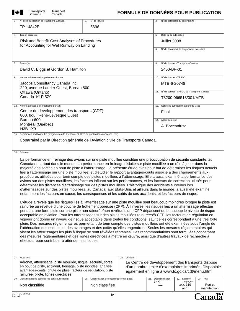
16. Abstract
17. Key Words
Aircraft, landing, wet runway, risk, safety, overrun, accident, braking, flooded runway, benefit-cost analysis, rainfall, dispatch factor, grooved runway, pilot, guidance material
18. Distribution Statement
Limited number of print copies available from the Transportation Development Centre. Also available online at www.tc.gc.ca/tdc/menu.htm
19. Security Classification (of this publication)
Unclassified
20. Security Classification (of this page)
Unclassified
21. Declassification (date)
—
22. No. of Pages xxx, 110,
apps
23. Price
Shipping/ Handling
CDT/TDC 79-005 Rev. 96 iii
Risk and Benefit-Cost Analyses of Procedures for Accounting for Wet Runway on Landing
Jacobs Consultancy Canada Inc. 220 Laurier Avenue West, Suite 500 Ottawa, Ontario Canada K1P 5Z9
Transportation Development Centre (TDC) 800 René Lévesque Blvd. West Suite 600 Montreal, Quebec H3B 1X9
Aircraft braking performance in wet runway conditions is a continuing safety concern, both in Canada and internationally. Degraded aircraft performance on wet runways has been a factor in the majority of aircraft accident overruns on landing. This study was conducted to determine the current risks of landing on a wet runway and the benefit-cost ratio of changes in procedures for accounting for wet runways on landing. It also examined aircraft performance on wet runways, factors affecting performance, and adjustment factors used for determining landing distances on wet runways. The accident history for landings on wet runways in Canada, the US and worldwide was also examined, including the factors involved, the consequences and costs of these accidents, and the risk factors. It was found that the risks of landing on wet runways are greatly reduced if the runways are grooved or have a porous friction course (PFC) overlay. Risks for landings during heavy rainfall on un-grooved/non-PFC runways were found to be much higher than acceptable risks in aviation. For landings on wet grooved/PFC runways, the current wet runway dispatch factors were found to provide an adequate level of risk in all but very heavy rainfall conditions. The reduction in risks and the benefits and costs were examined for a number of regulatory options for accounting for wet runways. Only those regulatory changes that focused on landings most at risk were found to be cost-effective. Recommendations are made regarding regulatory changes and guidance material, and for additional research work to assist in reducing the risks.
Transports Canada
Transport Canada FORMULE DE DONNÉES POUR PUBLICATION
1. No de la publication de Transports Canada
TP 14842E 2. No de l’étude
5696 3. No de catalogue du destinataire
4. Titre et sous-titre
5. Date de la publication
Juillet 2008
6. No de document de l’organisme exécutant
7. Auteur(s)
David C. Biggs et Gordon B. Hamilton 8. No de dossier - Transports Canada
2450-BP-01
9. Nom et adresse de l’organisme exécutant 10. No de dossier - TPSGC
MTB-6-20748
11. No de contrat - TPSGC ou Transports Canada
T8200-066513/001/MTB
12. Nom et adresse de l’organisme parrain 13. Genre de publication et période visée
Final
14. Agent de projet
A. Boccanfuso
15. Remarques additionnelles (programmes de financement, titres de publications connexes, etc.)
Coparrainé par la Direction générale de l’Aviation civile de Transports Canada.
16. Résumé
17. Mots clés
Aéronef, atterrissage, piste mouillée, risque, sécurité, sortie en bout de piste, accident, freinage, piste inondée, analyse avantages-coûts, chute de pluie, facteur de régulation, piste rainurée, pilote, lignes directrices
18. Diffusion
Le Centre de développement des transports dispose d’un nombre limité d’exemplaires imprimés. Disponible également en ligne à www.tc.gc.ca/cdt/menu.htm
19. Classification de sécurité (de cette publication)
Non classifiée
20. Classification de sécurité (de cette page)
Non classifiée
21. Déclassification (date)
—
22. Nombre de pages
xxx, 110 ann.
23. Prix
Port et manutention
CDT/TDC 79-005 Rev. 96 iv
Risk and Benefit-Cost Analyses of Procedures for Accounting for Wet Runway on Landing
Jacobs Consultancy Canada Inc. 220, avenue Laurier Ouest, Bureau 500 Ottawa (Ontario) Canada K1P 5Z9
Centre de développement des transports (CDT) 800, boul. René-Lévesque Ouest Bureau 600 Montréal (Québec) H3B 1X9
La performance en freinage des avions sur une piste mouillée constitue une préoccupation de sécurité constante, au Canada et partout dans le monde. La performance en freinage réduite sur piste mouillée a un rôle à jouer dans la majorité des sorties en bout de piste à l’atterrissage. La présente étude avait pour but de déterminer les risques actuels liés à l’atterrissage sur une piste mouillée, et d’étudier le rapport avantages-coûts associé à des changements aux procédures utilisées pour tenir compte des pistes mouillées à l’atterrissage. Elle a aussi examiné la performance des avions sur des pistes mouillées, les facteurs influant sur les performances, et les facteurs de correction utilisés pour déterminer les distances d’atterrissage sur des pistes mouillées. L’historique des accidents survenus lors d’atterrissages sur des pistes mouillées, au Canada, aux États-Unis et ailleurs dans le monde, a aussi été examiné, notamment les facteurs en cause, les conséquences et les coûts de ces accidents, et les facteurs de risque. L’étude a révélé que les risques liés à l’atterrissage sur une piste mouillée sont beaucoup moindres lorsque la piste est rainurée ou revêtue d’une couche de frottement poreuse (CFP). À l’inverse, les risques liés à un atterrissage effectué pendant une forte pluie sur une piste non rainurée/non revêtue d’une CFP dépassent de beaucoup le niveau de risque acceptable en aviation. Pour les atterrissages sur des pistes mouillées rainurées/à CFP, les facteurs de régulation en vigueur ont donné un niveau de risque acceptable dans toutes les conditions, sauf celles correspondant à une très forte pluie. Des mesures réglementaires permettant de tenir compte des pistes mouillées ont été examinées sous l’angle de l’atténuation des risques, et des avantages et des coûts qu’elles engendrent. Seules les mesures réglementaires qui visent les atterrissages les plus à risque se sont révélées rentables. Des recommandations sont formulées concernant des mesures réglementaires et des lignes directrices à mettre en œuvre, ainsi que d’autres travaux de recherche à effectuer pour contribuer à atténuer les risques.
v
Acknowledgments The authors would like to acknowledge the assistance of Mr. Jim White for his assistance is collecting information pertaining to the procedures, costs and experience of grooving runways in the US. The information is very helpful in assessing the options for improving the safety of landing on wet runways. The contribution of Mr. K.D.J. Owen for his comments and suggestions on the draft report are gratefully acknowledged. Finally, the assistance of Captain P.S. Carson, PEng PhD, Flight Technical Commercial Flight Standards, Transport Canada Civil Aviation, in providing information and making comments and corrections on the draft report is gratefully acknowledged.

vi
vii
Executive Summary
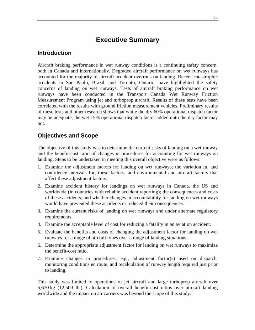
Introduction Aircraft braking performance in wet runway conditions is a continuing safety concern, both in Canada and internationally. Degraded aircraft performance on wet runways has accounted for the majority of aircraft accident overruns on landing. Recent catastrophic accidents in Sao Paulo, Brazil, and Toronto, Ontario, have highlighted the safety concerns of landing on wet runways. Tests of aircraft braking performance on wet runways have been conducted in the Transport Canada Wet Runway Friction Measurement Program using jet and turboprop aircraft. Results of these tests have been correlated with the results with ground friction measurement vehicles. Preliminary results of these tests and other research shows that while the dry 60% operational dispatch factor may be adequate, the wet 15% operational dispatch factor added onto the dry factor may not. Objectives and Scope The objective of this study was to determine the current risks of landing on a wet runway and the benefit-cost ratio of changes in procedures for accounting for wet runways on landing. Steps to be undertaken in meeting this overall objective were as follows: 1. Examine the adjustment factors for landing on wet runways; the variation in, and
confidence intervals for, these factors; and environmental and aircraft factors that affect these adjustment factors.
2. Examine accident history for landings on wet runways in Canada, the US and worldwide (in countries with reliable accident reporting); the consequences and costs of these accidents; and whether changes in accountability for landing on wet runways would have prevented these accidents or reduced their consequences.
3. Examine the current risks of landing on wet runways and under alternate regulatory requirements.
4. Examine the acceptable level of cost for reducing a fatality in an aviation accident. 5. Evaluate the benefits and costs of changing the adjustment factor for landing on wet
runways for a range of aircraft types over a range of landing situations. 6. Determine the appropriate adjustment factor for landing on wet runways to maximize
the benefit-cost ratio. 7. Examine changes in procedures; e.g., adjustment factor(s) used on dispatch,
monitoring conditions en route, and recalculation of runway length required just prior to landing.
This study was limited to operations of jet aircraft and large turboprop aircraft over 5,670 kg (12,500 lb.). Calculation of overall benefit-cost ratios over aircraft landing worldwide and the impact on air carriers was beyond the scope of this study.

viii
Methodology A detailed examination was conducted of historical wet runway landing overrun occurrence reports and studies, and of aircraft test data and analysis of aircraft landings performance on wet runways. The information and data collected were used to develop a computer model for estimating the distribution of actual landing distances in specific conditions and the changes in operations and costs to meet specific regulatory requirements on dispatch and prior to landing the aircraft. Outputs from the model were checked to ensure they were consistent with recent landing overrun experience. This model was used to estimate the risks and benefit-costs for a range of aircraft under various conditions so as to provide an understanding of the risks and the likely overall benefit-costs of the alternate regulatory options considered. Findings from the Accident/Incident Analysis
The risk of a jet or large turboprop aircraft overrunning the end of the runway on landing when the runway is wet varies by country/region and has declined over the past 30 years. Worldwide, the risk of an overrun accident when landing on a wet runway is approximately seven times greater than when the runway is dry based on accidents during the period 1990-2007.
The risks of overrun accidents when landing on wet runways are much lower in countries or regions where runways are grooved. The ratio of the risk of an overrun accident on a wet runway compared to the risks on a dry runway were estimated to be approximately: • 10 on un-grooved/non-PFC (porous friction course) runways • 2.5 on grooved/PFC runways Grooved or PFC runways reduced the risks of an accident on a wet runway by approximately 75%.
The risks of landing overruns on wet runways for aircraft without reverse thrust are approximately six times greater than for aircraft with reverse thrust.
The overrun accident rate on wet runways in Canada is six times the rate for the US. The rate for other countries is three times the US rate.
Overrun landing accidents are much more likely during heavy rainfall, especially on un-grooved runways.
Heavy rainfall is very often associated with other conditions such as strong and gusty winds, wind shear and poor visibility, which by themselves are common factors associated with overrun accidents. This makes heavy rainfall an especially hazardous condition.
ix
Findings on the Frequency and Reporting of Wet Runway Conditions
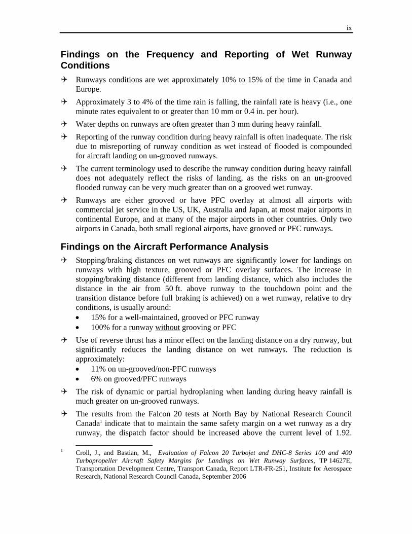
Runways conditions are wet approximately 10% to 15% of the time in Canada and Europe.
Approximately 3 to 4% of the time rain is falling, the rainfall rate is heavy (i.e., one minute rates equivalent to or greater than 10 mm or 0.4 in. per hour).
Water depths on runways are often greater than 3 mm during heavy rainfall. Reporting of the runway condition during heavy rainfall is often inadequate. The risk
due to misreporting of runway condition as wet instead of flooded is compounded for aircraft landing on un-grooved runways.
The current terminology used to describe the runway condition during heavy rainfall does not adequately reflect the risks of landing, as the risks on an un-grooved flooded runway can be very much greater than on a grooved wet runway.
Runways are either grooved or have PFC overlay at almost all airports with commercial jet service in the US, UK, Australia and Japan, at most major airports in continental Europe, and at many of the major airports in other countries. Only two airports in Canada, both small regional airports, have grooved or PFC runways.
Findings on the Aircraft Performance Analysis
Stopping/braking distances on wet runways are significantly lower for landings on runways with high texture, grooved or PFC overlay surfaces. The increase in stopping/braking distance (different from landing distance, which also includes the distance in the air from 50 ft. above runway to the touchdown point and the transition distance before full braking is achieved) on a wet runway, relative to dry conditions, is usually around: • 15% for a well-maintained, grooved or PFC runway • 100% for a runway without grooving or PFC
Use of reverse thrust has a minor effect on the landing distance on a dry runway, but significantly reduces the landing distance on wet runways. The reduction is approximately: • 11% on un-grooved/non-PFC runways • 6% on grooved/PFC runways
The risk of dynamic or partial hydroplaning when landing during heavy rainfall is much greater on un-grooved runways.
The results from the Falcon 20 tests at North Bay by National Research Council Canada1 indicate that to maintain the same safety margin on a wet runway as a dry runway, the dispatch factor should be increased above the current level of 1.92. ___________________
1 Croll, J., and Bastian, M., Evaluation of Falcon 20 Turbojet and DHC-8 Series 100 and 400 Turbopropeller Aircraft Safety Margins for Landings on Wet Runway Surfaces, TP 14627E, Transportation Development Centre, Transport Canada, Report LTR-FR-251, Institute for Aerospace Research, National Research Council Canada, September 2006
x
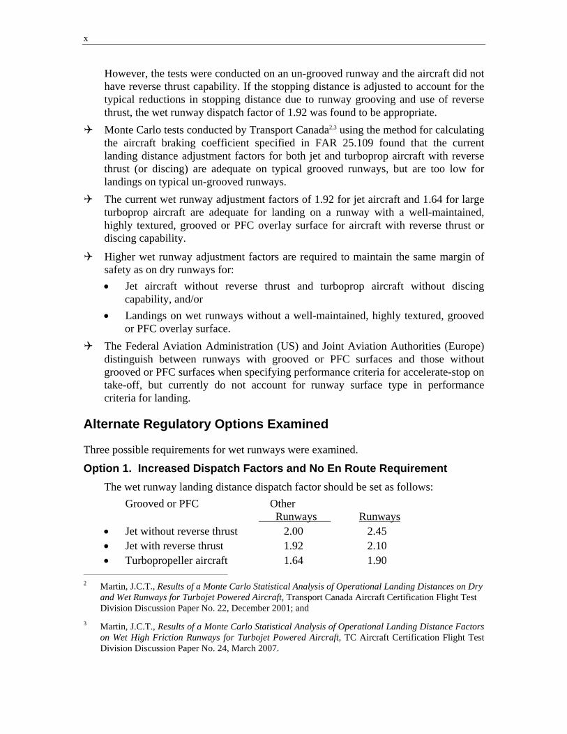
However, the tests were conducted on an un-grooved runway and the aircraft did not have reverse thrust capability. If the stopping distance is adjusted to account for the typical reductions in stopping distance due to runway grooving and use of reverse thrust, the wet runway dispatch factor of 1.92 was found to be appropriate.
Monte Carlo tests conducted by Transport Canada2,3 using the method for calculating the aircraft braking coefficient specified in FAR 25.109 found that the current landing distance adjustment factors for both jet and turboprop aircraft with reverse thrust (or discing) are adequate on typical grooved runways, but are too low for landings on typical un-grooved runways.
The current wet runway adjustment factors of 1.92 for jet aircraft and 1.64 for large turboprop aircraft are adequate for landing on a runway with a well-maintained, highly textured, grooved or PFC overlay surface for aircraft with reverse thrust or discing capability.
Higher wet runway adjustment factors are required to maintain the same margin of safety as on dry runways for: • Jet aircraft without reverse thrust and turboprop aircraft without discing
capability, and/or • Landings on wet runways without a well-maintained, highly textured, grooved
or PFC overlay surface. The Federal Aviation Administration (US) and Joint Aviation Authorities (Europe)
distinguish between runways with grooved or PFC surfaces and those without grooved or PFC surfaces when specifying performance criteria for accelerate-stop on take-off, but currently do not account for runway surface type in performance criteria for landing.
Alternate Regulatory Options Examined Three possible requirements for wet runways were examined.
Option 1. Increased Dispatch Factors and No En Route Requirement The wet runway landing distance dispatch factor should be set as follows:
Grooved or PFC Other Runways Runways • Jet without reverse thrust 2.00 2.45 • Jet with reverse thrust 1.92 2.10 • Turbopropeller aircraft 1.64 1.90
________________________________________________
2 Martin, J.C.T., Results of a Monte Carlo Statistical Analysis of Operational Landing Distances on Dry and Wet Runways for Turbojet Powered Aircraft, Transport Canada Aircraft Certification Flight Test Division Discussion Paper No. 22, December 2001; and
3 Martin, J.C.T., Results of a Monte Carlo Statistical Analysis of Operational Landing Distance Factors
on Wet High Friction Runways for Turbojet Powered Aircraft, TC Aircraft Certification Flight Test Division Discussion Paper No. 24, March 2007.
xi
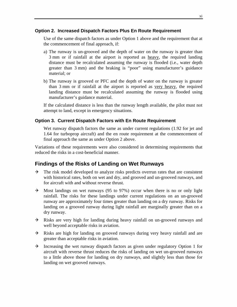
Option 2. Increased Dispatch Factors Plus En Route Requirement Use of the same dispatch factors as under Option 1 above and the requirement that at
the commencement of final approach, if:
a) The runway is un-grooved and the depth of water on the runway is greater than 3 mm or if rainfall at the airport is reported as heavy, the required landing distance must be recalculated assuming the runway is flooded (i.e., water depth greater than 3 mm) and the braking is “poor” using manufacturer’s guidance material; or
b) The runway is grooved or PFC and the depth of water on the runway is greater than 3 mm or if rainfall at the airport is reported as very heavy, the required landing distance must be recalculated assuming the runway is flooded using manufacturer’s guidance material.
If the calculated distance is less than the runway length available, the pilot must not attempt to land, except in emergency situations.
Option 3. Current Dispatch Factors with En Route Requirement Wet runway dispatch factors the same as under current regulations (1.92 for jet and
1.64 for turboprop aircraft) and the en route requirement at the commencement of final approach the same as under Option 2 above.
Variations of these requirements were also considered in determining requirements that reduced the risks in a cost-beneficial manner. Findings of the Risks of Landing on Wet Runways
The risk model developed to analyze risks predicts overrun rates that are consistent with historical rates, both on wet and dry, and grooved and un-grooved runways, and for aircraft with and without reverse thrust.
Most landings on wet runways (95 to 97%) occur when there is no or only light rainfall. The risks for these landings under current regulations on an un-grooved runway are approximately four times greater than landing on a dry runway. Risks for landing on a grooved runway during light rainfall are marginally greater than on a dry runway.
Risks are very high for landing during heavy rainfall on un-grooved runways and well beyond acceptable risks in aviation.
Risks are high for landing on grooved runways during very heavy rainfall and are greater than acceptable risks in aviation.
Increasing the wet runway dispatch factors as given under regulatory Option 1 for aircraft with reverse thrust reduces the risks of landing on wet un-grooved runways to a little above those for landing on dry runways, and slightly less than those for landing on wet grooved runways.
xii
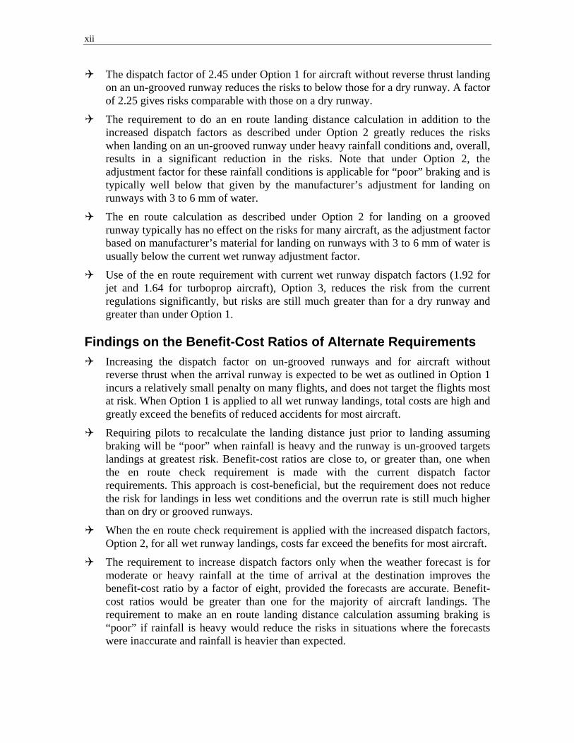
The dispatch factor of 2.45 under Option 1 for aircraft without reverse thrust landing on an un-grooved runway reduces the risks to below those for a dry runway. A factor of 2.25 gives risks comparable with those on a dry runway.
The requirement to do an en route landing distance calculation in addition to the increased dispatch factors as described under Option 2 greatly reduces the risks when landing on an un-grooved runway under heavy rainfall conditions and, overall, results in a significant reduction in the risks. Note that under Option 2, the adjustment factor for these rainfall conditions is applicable for “poor” braking and is typically well below that given by the manufacturer’s adjustment for landing on runways with 3 to 6 mm of water.
The en route calculation as described under Option 2 for landing on a grooved runway typically has no effect on the risks for many aircraft, as the adjustment factor based on manufacturer’s material for landing on runways with 3 to 6 mm of water is usually below the current wet runway adjustment factor.
Use of the en route requirement with current wet runway dispatch factors (1.92 for jet and 1.64 for turboprop aircraft), Option 3, reduces the risk from the current regulations significantly, but risks are still much greater than for a dry runway and greater than under Option 1.
Findings on the Benefit-Cost Ratios of Alternate Requirements
Increasing the dispatch factor on un-grooved runways and for aircraft without reverse thrust when the arrival runway is expected to be wet as outlined in Option 1 incurs a relatively small penalty on many flights, and does not target the flights most at risk. When Option 1 is applied to all wet runway landings, total costs are high and greatly exceed the benefits of reduced accidents for most aircraft.
Requiring pilots to recalculate the landing distance just prior to landing assuming braking will be “poor” when rainfall is heavy and the runway is un-grooved targets landings at greatest risk. Benefit-cost ratios are close to, or greater than, one when the en route check requirement is made with the current dispatch factor requirements. This approach is cost-beneficial, but the requirement does not reduce the risk for landings in less wet conditions and the overrun rate is still much higher than on dry or grooved runways.
When the en route check requirement is applied with the increased dispatch factors, Option 2, for all wet runway landings, costs far exceed the benefits for most aircraft.
The requirement to increase dispatch factors only when the weather forecast is for moderate or heavy rainfall at the time of arrival at the destination improves the benefit-cost ratio by a factor of eight, provided the forecasts are accurate. Benefit-cost ratios would be greater than one for the majority of aircraft landings. The requirement to make an en route landing distance calculation assuming braking is “poor” if rainfall is heavy would reduce the risks in situations where the forecasts were inaccurate and rainfall is heavier than expected.
xiii
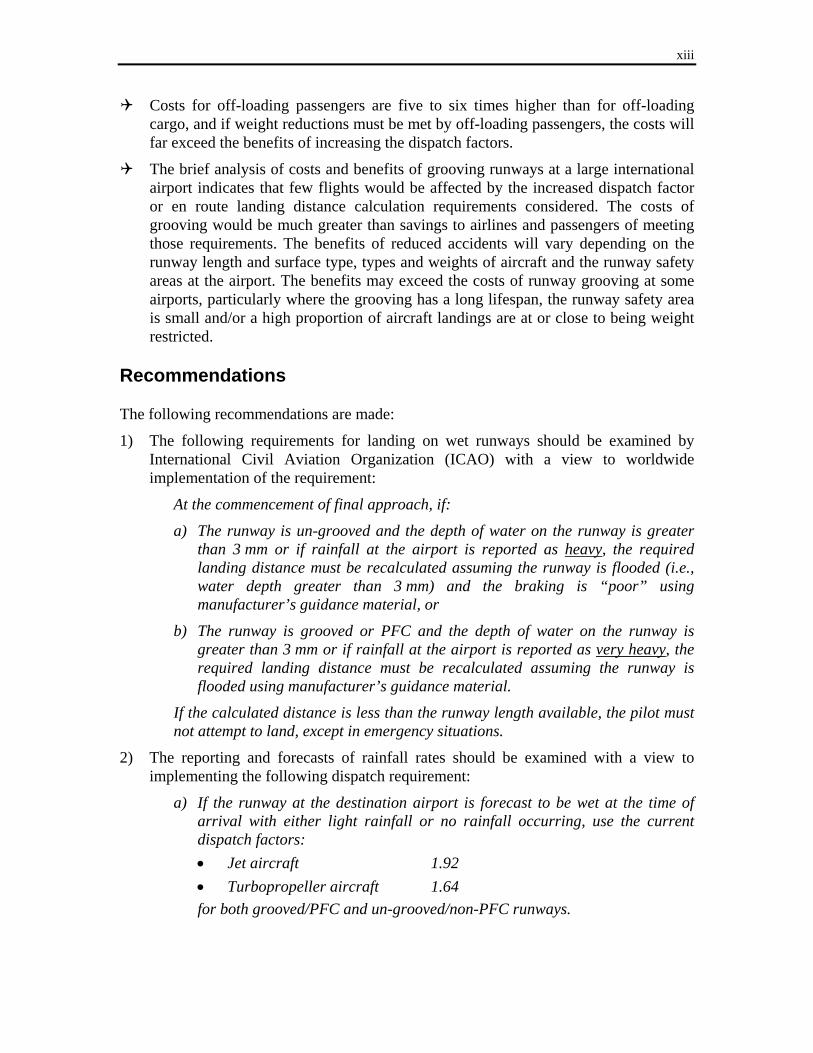
Costs for off-loading passengers are five to six times higher than for off-loading cargo, and if weight reductions must be met by off-loading passengers, the costs will far exceed the benefits of increasing the dispatch factors.
The brief analysis of costs and benefits of grooving runways at a large international airport indicates that few flights would be affected by the increased dispatch factor or en route landing distance calculation requirements considered. The costs of grooving would be much greater than savings to airlines and passengers of meeting those requirements. The benefits of reduced accidents will vary depending on the runway length and surface type, types and weights of aircraft and the runway safety areas at the airport. The benefits may exceed the costs of runway grooving at some airports, particularly where the grooving has a long lifespan, the runway safety area is small and/or a high proportion of aircraft landings are at or close to being weight restricted.
Recommendations The following recommendations are made:
1) The following requirements for landing on wet runways should be examined by International Civil Aviation Organization (ICAO) with a view to worldwide implementation of the requirement:
At the commencement of final approach, if:
a) The runway is un-grooved and the depth of water on the runway is greater than 3 mm or if rainfall at the airport is reported as heavy, the required landing distance must be recalculated assuming the runway is flooded (i.e., water depth greater than 3 mm) and the braking is “poor” using manufacturer’s guidance material, or
b) The runway is grooved or PFC and the depth of water on the runway is greater than 3 mm or if rainfall at the airport is reported as very heavy, the required landing distance must be recalculated assuming the runway is flooded using manufacturer’s guidance material.
If the calculated distance is less than the runway length available, the pilot must not attempt to land, except in emergency situations.
2) The reporting and forecasts of rainfall rates should be examined with a view to implementing the following dispatch requirement:
a) If the runway at the destination airport is forecast to be wet at the time of arrival with either light rainfall or no rainfall occurring, use the current dispatch factors: • Jet aircraft 1.92 • Turbopropeller aircraft 1.64 for both grooved/PFC and un-grooved/non-PFC runways.
xiv
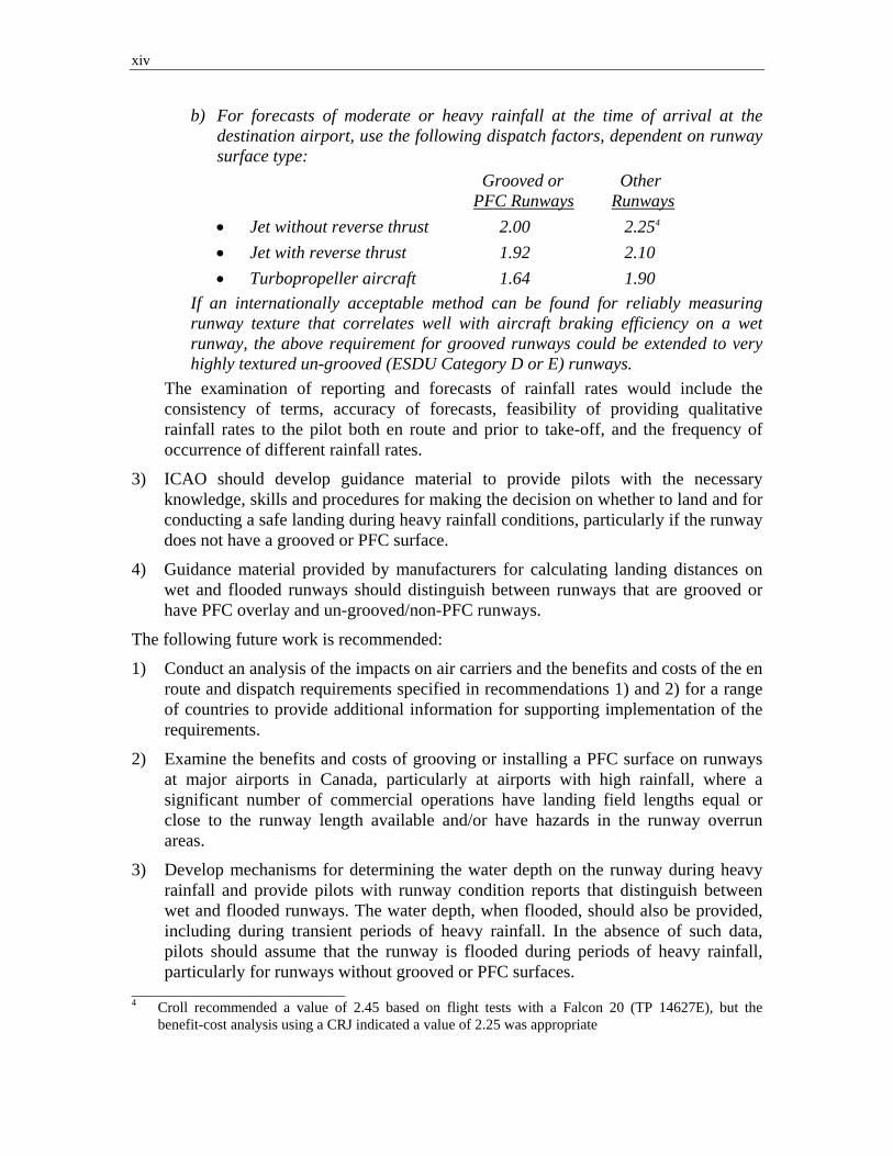
b) For forecasts of moderate or heavy rainfall at the time of arrival at the destination airport, use the following dispatch factors, dependent on runway surface type: Grooved or Other PFC Runways Runways • Jet without reverse thrust 2.00 2.254 • Jet with reverse thrust 1.92 2.10 • Turbopropeller aircraft 1.64 1.90
If an internationally acceptable method can be found for reliably measuring runway texture that correlates well with aircraft braking efficiency on a wet runway, the above requirement for grooved runways could be extended to very highly textured un-grooved (ESDU Category D or E) runways.
The examination of reporting and forecasts of rainfall rates would include the consistency of terms, accuracy of forecasts, feasibility of providing qualitative rainfall rates to the pilot both en route and prior to take-off, and the frequency of occurrence of different rainfall rates.
3) ICAO should develop guidance material to provide pilots with the necessary knowledge, skills and procedures for making the decision on whether to land and for conducting a safe landing during heavy rainfall conditions, particularly if the runway does not have a grooved or PFC surface.
4) Guidance material provided by manufacturers for calculating landing distances on wet and flooded runways should distinguish between runways that are grooved or have PFC overlay and un-grooved/non-PFC runways.
The following future work is recommended:
1) Conduct an analysis of the impacts on air carriers and the benefits and costs of the en route and dispatch requirements specified in recommendations 1) and 2) for a range of countries to provide additional information for supporting implementation of the requirements.
2) Examine the benefits and costs of grooving or installing a PFC surface on runways at major airports in Canada, particularly at airports with high rainfall, where a significant number of commercial operations have landing field lengths equal or close to the runway length available and/or have hazards in the runway overrun areas.
3) Develop mechanisms for determining the water depth on the runway during heavy rainfall and provide pilots with runway condition reports that distinguish between wet and flooded runways. The water depth, when flooded, should also be provided, including during transient periods of heavy rainfall. In the absence of such data, pilots should assume that the runway is flooded during periods of heavy rainfall, particularly for runways without grooved or PFC surfaces.
_____________________________ 4 Croll recommended a value of 2.45 based on flight tests with a Falcon 20 (TP 14627E), but the
benefit-cost analysis using a CRJ indicated a value of 2.25 was appropriate
xv
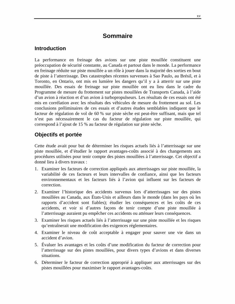
Sommaire
Introduction La performance en freinage des avions sur une piste mouillée constituent une préoccupation de sécurité constante, au Canada et partout dans le monde. La performance en freinage réduite sur piste mouillée a un rôle à jouer dans la majorité des sorties en bout de piste à l’atterrissage. Des catastrophes récentes survenues à Sao Paulo, au Brésil, et à Toronto, en Ontario, ont mis en lumière les dangers qu’il y a à atterrir sur une piste mouillée. Des essais de freinage sur piste mouillée ont eu lieu dans le cadre du Programme de mesure du frottement sur pistes mouillées de Transports Canada, à l’aide d’un avion à réaction et d’un avion à turbopropulseurs. Les résultats de ces essais ont été mis en corrélation avec les résultats des véhicules de mesure du frottement au sol. Les conclusions préliminaires de ces essais et d’autres études semblables indiquent que le facteur de régulation de vol de 60 % sur piste sèche est peut-être suffisant, mais que tel n’est pas nécessairement le cas du facteur de régulation sur piste mouillée, qui correspond à l’ajout de 15 % au facteur de régulation sur piste sèche. Objectifs et portée Cette étude avait pour but de déterminer les risques actuels liés à l’atterrissage sur une piste mouillée, et d’étudier le rapport avantages-coûts associé à des changements aux procédures utilisées pour tenir compte des pistes mouillées à l’atterrissage. Cet objectif a donné lieu à divers travaux : 1. Examiner les facteurs de correction appliqués aux atterrissages sur piste mouillée, la
variabilité de ces facteurs et leurs intervalles de confiance, ainsi que les facteurs environnementaux et les facteurs liés à l’avion qui influent sur les facteurs de correction.
2. Examiner l’historique des accidents survenus lors d’atterrissages sur des pistes mouillées au Canada, aux États-Unis et ailleurs dans le monde (dans les pays où les rapports d’accident sont fiables); étudier les conséquences et les coûts de ces accidents, et voir si d’autres façons de tenir compte d’une piste mouillée à l’atterrissage auraient pu empêcher ces accidents ou atténuer leurs conséquences.
3. Examiner les risques actuels liés à l’atterrissage sur une piste mouillée et les risques qu’entraînerait une modification des exigences réglementaires.
4. Examiner le niveau de coût acceptable à engager pour sauver une vie dans un accident d’avion.
5. Évaluer les avantages et les coûts d’une modification du facteur de correction pour l’atterrissage sur des pistes mouillées, pour divers types d’avions et dans diverses situations.
6. Déterminer le facteur de correction approprié à appliquer aux atterrissages sur des pistes mouillées pour maximiser le rapport avantages-coûts.

xvi
7. Examiner les changements de procédures envisagés : facteur(s) de correction appliqué(s) avant le départ de l’avion, suivi des conditions en route, et nouveau calcul de la longueur de piste nécessaire, juste avant l’atterrissage.
Cette étude a porté uniquement sur les avions à réaction et sur les gros avions à turbopropulseurs de plus de 5 670 kg (12 500 lb). Étaient exclus de sa portée le calcul des rapports avantages-coûts globaux pour les avions atterrissant partout dans le monde, ainsi que les répercussions sur les transporteurs aériens.
Méthodologie Les chercheurs ont examiné en détail les rapports d’incident et les études portant sur des sorties en bout de piste lors d’atterrissages sur des pistes mouillées, les données d’essais d’avions et les analyses des performances d’avions à l’atterrissage sur des pistes mouillées. L’information et les données ainsi colligées ont servi à développer un modèle informatique pour estimer la distribution des distances d’atterrissage réelles dans des conditions spécifiques, et les changements dans les opérations et les coûts nécessaires pour respecter des mesures réglementaires précises applicables lors de la régulation du vol (avant le départ), et avant l’atterrissage. Les résultats générés par le modèle ont été validés en regard de cas récents de sortie en bout de piste à l’atterrissage. Ce modèle a été utilisé pour estimer les risques et les avantages-coûts pour divers types d’avions dans diverses conditions, de manière à avoir une idée des risques et des avantages-coûts globaux vraisemblablement associés aux nouvelles mesures réglementaires envisagées. Analyse des accidents/incidents – Résultats
Le risque qu’un avion à réaction ou qu’un gros avion à turbopropulseurs dépasse l’extrémité de la piste à l’atterrissage, lorsque celle-ci est mouillée, varie selon le pays/la région et a diminué ces 30 dernières années. L’examen des accidents survenus de 1990 à 2007 a révélé que, à l’échelle mondiale, le risque d’une sortie en bout de piste lors d’un atterrissage sur piste mouillée est environ sept fois plus élevé que lors d’un atterrissage sur piste sèche.
Le risque de sortie en bout de piste lors d’un atterrissage sur piste mouillée est beaucoup plus faible dans les pays ou les régions où les pistes sont rainurées. Le rapport du risque de sortie en bout de piste, sur piste mouillée, au même risque sur piste sèche est établi à environ : • 10 sur des pistes non rainurées/non revêtues d’une CFP (couche de frottement
poreuse); • 2,5 sur des pistes rainurées/revêtues d’une CFP. Ainsi, les pistes rainurées ou revêtues d’une CFP réduisent d’environ 75 % le risque d’accident sur une piste mouillée.
Le risque de sortie en bout de piste lors d’un atterrissage sur piste mouillée est environ six fois plus élevé pour un avion sans fonction d’inversion de poussée que pour un avion avec inversion de poussée.

xvii
Le taux de sortie en bout de piste sur piste mouillée est six fois plus élevé au Canada qu’aux États-Unis. Ailleurs dans le monde, ce taux est trois fois plus élevé qu’aux États-Unis.
Plus la pluie est forte, plus la probabilité de sortie en bout de piste à l’atterrissage est grande, surtout lorsque la piste n’est pas rainurée.
Une forte pluie est très souvent associée à d’autres conditions météorologiques difficiles, comme des vents forts soufflant en rafales, le cisaillement du vent et une faible visibilité, qui contribuent souvent aux sorties de piste. D’où le danger particulier que représentent les fortes pluies.
Fréquence de pistes mouillées et comptes rendus de piste mouillée – Résultats
Au Canada et en Europe, les pistes sont qualifiées de mouillées de 10 % à 15 % du temps environ.
Lorsqu’il pleut, la pluie est forte (intensité à la minute équivalente à 10 mm ou 0,4 po à l’heure) pendant 3 % à 4 % du temps environ.
Pendant une forte pluie, la profondeur de l’eau sur la piste est souvent supérieure à 3 mm.
Le compte rendu de l’état de la piste pendant une forte pluie est souvent inadéquat. Le risque lié à un compte rendu inexact, faisant état d’une piste mouillée plutôt qu’inondée, est d’autant plus élevé que la piste n’est pas rainurée.
La terminologie actuellement utilisée pour décrire l’état de la piste pendant une forte pluie ne reflète pas adéquatement les risques liés à l’atterrissage, car les risques peuvent être beaucoup plus élevés sur une piste inondée non rainurée que sur une piste mouillée rainurée.
À presque tous les aéroports accueillant des avions à réaction commerciaux aux États-Unis, au Royaume-Uni, en Australie et au Japon, à la plupart des grands aéroports d’Europe continentale et à beaucoup des grands aéroports des autres pays, les pistes sont soit rainurées, soit revêtues d’une CFP. Or, au Canada, seuls deux aéroports, plus précisément deux petits aéroports régionaux, ont des pistes rainurées ou revêtues d’une CFP.
Analyse des performances des avions – Résultats
Les distances d’arrêt/de freinage lors d’atterrissages sur des pistes mouillées sont significativement plus courtes lorsque la piste présente une forte rugosité ou qu’elle est soit rainurée soit revêtue d’une CFP. La hausse de la distance d’arrêt/de freinage sur une piste mouillée (à ne pas confondre avec la distance d’atterrissage, qui comprend aussi la distance parcourue dans les airs à partir du point où l’avion est à une hauteur de 50 pi au-dessus de la piste jusqu’au toucher, et la distance au sol jusqu’à l’arrêt complet) par rapport à une piste sèche, se situe habituellement autour de :
xviii
• 15 % dans le cas d’une piste rainurée ou revêtue d’une CFP et bien entretenue; • 100 % pour une piste non rainurée ou non revêtue d’une CFP.
L’utilisation de l’inversion de poussée a peu d’effet sur la distance d’atterrissage sur une piste sèche, mais elle diminue de façon importante la distance d’atterrissage sur une piste mouillée. Cette réduction s’établit à environ : • 11 % sur une piste non rainurée/non revêtue d’une CFP; • 6 % sur une piste rainurée/revêtue d’une CFP.
Le risque d’aquaplanage dynamique ou partiel lors d’un atterrissage pendant une forte pluie est d’autant plus élevé que la piste n’est pas rainurée.
Les résultats des essais effectués à l’aide d’un Falcon 20 à North Bay par le Conseil national de recherches du Canada1 indiquent que pour maintenir la même marge de sécurité sur une piste mouillée que sur une piste sèche, le facteur de régulation devrait être porté au-delà du 1,92 actuel. Toutefois, les essais ont eu lieu sur une piste non rainurée, avec un avion non doté de la fonction d’inversion de poussée. Si on corrige la distance d’arrêt pour tenir compte de la diminution de la distance d’arrêt due au rainurage de la piste et à l’utilisation de l’inversion de poussée, le facteur de régulation de 1,92 pour un atterrissage sur piste mouillée est jugé adéquat.
Les simulations de Monte Carlo réalisées par Transports Canada2,3 à l’aide de la méthode de calcul du coefficient de freinage précisée dans le règlement FAR 25.109 ont révélé que les facteurs de correction de la distance d’atterrissage actuellement appliqués aux avions à réaction et aux avions à turbopropulseurs à inversion de poussée (ou effet de disque) sont adéquats pour des pistes rainurées, mais trop faibles pour des pistes non rainurées.
Les facteurs de correction actuels pour l’atterrissage sur piste mouillée (1,92 pour les avions à réaction et 1,64 pour les gros avions à turbopropulseurs) sont suffisants si l’avion est doté de la fonction d’inversion de poussée ou d’effet de disque, et si la piste est bien entretenue, rainurée, revêtue d’une CFP ou qu’elle présente une forte rugosité.
Des facteurs de correction plus élevés pour les atterrissages sur piste mouillée sont nécessaires pour maintenir la même marge de sécurité que lors des atterrissages sur piste sèche, dans les cas suivants : • avion à réaction sans inversion de poussée et avion à turbopropulseurs sans effet
de disque, et/ou ___________________________ 1. Croll, J., et Bastian, M., Evaluation of Falcon 20 Turbojet and DHC-8 Series 100 and 400
Turbopropeller Aircraft Safety Margins for Landings on Wet Runway Surfaces, TP 14627E, Centre de développement des transports, Transports Canada, Rapport LTR-FR-251, Institut de recherche aérospatiale, Conseil national de recherches du Canada, Septembre 2006.
2. Martin, J.C.T., Results of a Monte Carlo Statistical Analysis of Operational Landing Distances on Dry and Wet Runways for Turbojet Powered Aircraft, Document de travail No 22de la division des Essais en vol de la Certification des aéronefs de Transports Canada, Decembre 2001.
3. Martin, J.C.T., Results of a Monte Carlo Statistical Analysis of Operational Landing Distance Factors on Wet High Friction Runways for Turbojet Powered Aircraft, Document de travail No 24 de la division des Essais en vol de la Certification des aéronefs de Transports Canada, Mars 2007.
xix
• atterrissage sur une piste mouillée mal entretenue, peu rugueuse, non rainurée et non revêtue d’une CFP.
La Federal Aviation Administration (aux États-Unis) et les Autorités conjointes de l’aviation (Europe) font une distinction entre les pistes rainurées ou revêtues d’une CFP et celles qui ne le sont pas, lors de l’établissement des critères de performance liés aux distances d’accélération-arrêt au décollage. Mais cette distinction ne compte pas dans les critères de performance à l’atterrissage.
Mesures réglementaires de remplacement envisagées Trois mesures réglementaires possibles ont été examinées pour les atterrissages sur des pistes mouillées.
Option 1. Hausse des facteurs de régulation, sans nouveau calcul en route Le facteur de régulation pour la distance d’atterrissage sur piste mouillée devrait être établi comme suit : Pistes rainurées ou à CFP Autres pistes • Avion à réaction
sans inversion de poussée 2,00 2,45 • Avion à réaction
avec inversion de poussée 1,92 2,10 • Avion à turbopropulseurs 1,64 1,90
Option 2. Hausse des facteurs de régulation, avec nouveau calcul en route Utilisation des mêmes facteurs de régulation que dans l’option 1 ci-dessus. De plus, si, au moment où débute l’approche finale :
a) vers une piste non rainurée, la profondeur d’eau sur la piste dépasse 3 mm ou si l’aéroport signale une pluie forte sur l’aéroport, la distance d’atterrissage nécessaire doit être recalculée en supposant que la piste est inondée (que la profondeur d’eau est supérieure à 3 mm) et que le freinage est « mauvais », selon les lignes directrices du constructeur;
b) vers une piste rainurée ou revêtue d’une CFP, la profondeur d’eau sur la piste dépasse 3 mm ou si l’aéroport signale une pluie très forte sur l’aéroport, la distance d’atterrissage nécessaire doit être recalculée en supposant que la piste est inondée, selon les lignes directrices du constructeur.
Si la distance ainsi recalculée est inférieure à la longueur de piste utilisable, le pilote ne doit pas tenter un atterrissage, sauf en cas d’urgence.
Option 3. Facteurs de régulation en vigueur, avec nouveau calcul en route Les facteurs de régulation sur piste mouillée demeurent inchangés (1,92 pour avions à réaction et 1,64 pour avions à turbopropulseurs) et l’exigence d’un nouveau calcul en route lorsque débute l’approche finale est identique à celle de l’option 2 ci-dessus.
xx
Diverses variantes de ces mesures ont aussi examinées, pour déterminer celles qui atténuaient les risques dans le meilleur rapport avantages-coûts. Risques liés à l’atterrissage sur une piste mouillée – Résultats
Le modèle informatique développé pour analyser les risques prédit des taux de sortie de piste semblables aux taux historiques, sur piste mouillée et sur piste sèche, sur piste rainurée et non rainurée, et dans le cas d’avions avec et sans inversion de poussée.
La plupart (95 % à 97 %) des atterrissages sur piste mouillée se produisent lorsqu’il ne pleut pas ou qu’il pleut légèrement. Compte tenu des règles en vigueur, lorsque la piste n’est pas rainurée, les risques liés à ces atterrissages sont environ quatre fois plus élevés que lorsque la piste est sèche. En d’autres mots, il est juste un peu plus risqué d’atterrir sur une piste rainurée sous une pluie légère, que sur une piste sèche.
Les risques liés à l’atterrissage sur une piste non rainurée lorsqu’il pleut fort sont très élevés, et ils dépassent de beaucoup le niveau de risque acceptable en aviation.
Les risques liés à l’atterrissage sur une piste rainurée lorsqu’il pleut très fort sont très élevés, et ils dépassent le niveau de risque acceptable en aviation.
La hausse des facteurs de régulation sur piste mouillée, comme le prévoit l’option 1 pour les avions sans inversion de poussée, atténue les risques liés à l’atterrissage sur des pistes mouillées non rainurées : ceux-ci deviennent légèrement supérieurs aux risques liés aux atterrissages sur piste sèche, et légèrement inférieurs aux risques associés aux atterrissages sur piste mouillée rainurée.
Le facteur de régulation de 2,45 prévu par l’option 1 pour les avions sans inversion de poussée atterrissant sur une piste non rainurée atténue le risque en-deçà du risque sur piste sèche. Un facteur de 2,25 conduit à un risque comparable à celui associé à une piste sèche.
L’option 2, qui comporte à la fois une hausse des facteurs de régulation et un nouveau calcul de la distance d’atterrissage en route, atténue de beaucoup le risque lié à un atterrissage sur une piste non rainurée pendant une forte pluie, et elle mène à une diminution importante du risque. Il convient de noter que selon l’option 2, le facteur de correction en cas de forte pluie est applicable au « mauvais » freinage, et il est habituellement bien en deçà du facteur de correction du constructeur pour l’atterrissage sur des pistes couvertes de 3 mm à 6 mm d’eau.
Pour de nombreux avions, le calcul en route de la distance d’atterrissage sur une piste rainurée mouillée, décrit à l’option 2, n’a pas d’effet sur les risques, car le facteur de correction donné par le manuel du constructeur pour les atterrissages sur des pistes couvertes de 3 mm à 6 mm d’eau est habituellement inférieur au facteur de correction sur piste mouillée en vigueur.
La conjonction d’un nouveau calcul en route et du facteur de régulation sur piste mouillée en vigueur (1,92 pour les avions à réaction et 1,64 pour les avions à turbopropulseurs), soit l’option 3, atténue de beaucoup le risque par rapport aux
xxi
règles actuelles, mais celui-ci demeure beaucoup plus élevé que pour une piste sèche, et plus élevé qu’en vertu de l’option 1.
Rapports avantages-coûts associés aux nouvelles mesures – Résultats
Hausser le facteur de régulation pour l’atterrissage d’avions sans inversion de poussée sur des pistes non rainurées, lorsqu’il est prévu que la piste d’arrivée sera mouillée, comme le décrit l’option 1, pénalise de nombreux vols, mais assez peu. Toutefois, cette mesure ne vise pas les vols les plus à risque. L’application de l’option 1 à tous les atterrissages sur piste mouillée entraînerait des coûts élevés, qui dépasseraient largement les avantages d’une diminution des accidents pour la plupart des avions.
Exiger des pilotes qu’ils calculent de nouveau la distance d’atterrissage juste avant d’atterrir en supposant que le freinage sera « mauvais », lorsqu’il pleut fortement et que la piste n’est pas rainurée, vise les atterrissages les plus risqués. Les rapports avantages-coûts sont autour de l’unité lorsque le nouveau calcul en route est combiné au facteur de régulation en vigueur. Cette approche présente donc un bon rapport avantages-coûts, mais elle n’atténue pas les risques liés aux atterrissages dans des conditions de pluie moins forte, et le taux de sortie de piste demeure beaucoup plus élevé que lors d’atterrissages sur des pistes sèches ou rainurées.
Lorsque l’exigence d’un nouveau calcul en route est appliqué en même temps que des facteurs de régulation accrus (option 2) à tous les atterrissages sur piste mouillée, les coûts dépassent largement les avantages, pour la plupart des avions.
L’exigence de hausser les facteurs de régulation uniquement lorsque la météo prévoit une pluie modérée ou forte au moment de l’arrivée à destination multiplie par huit le rapport avantages-coûts, pour autant que les prévisions soient exactes. Les rapports avantages-coûts seraient supérieurs à l’unité pour la majorité des atterrissages. L’exigence de calculer la distance d’atterrissage en route en supposant un « mauvais » freinage si la pluie est forte, aurait pour effet de réduire les risques dans des situations où les prévisions sont inexactes, notamment que la pluie est plus forte que prévu.
Il est cinq à six fois plus coûteux de faire descendre des passagers que de décharger des marchandises, et si l’on doit demander à des passagers de descendre pour réduire le poids de l’avion, les coûts dépasseront de beaucoup les avantages de hausser les facteurs de régulation.
La brève analyse des coûts et avantages associés au rainurage des pistes à un grand aéroport international révèle que peu de vols seraient visés par les mesures envisagées, soit la hausse du facteur de régulation ou un nouveau calcul en route de la distance d’atterrissage. Les coûts de rainurage seraient beaucoup plus élevés que les économies que pourraient réaliser les compagnies aériennes et les passagers simplement en respectant ces exigences. Les avantages d’une diminution du nombre d’accidents varieront en fonction de la longueur de la piste et du type de surface, du type et du poids de l’avion, et des aires de sécurité d’extrémité de piste. À certains
xxii
aéroports, les avantages du rainurage peuvent en dépasser les coûts, surtout lorsque le rainurage dure longtemps, que l’aire de sécurité d’extrémité de piste est petite et/ou qu’une grande proportion des avions sont sujets (ou quasi sujets) à des restrictions de poids à l’atterrissage.
Recommandations Voici les recommandations formulées au terme de l’étude :
1) L’Organisation de l’aviation civile internationale (OACI) devrait étudier les exigences ci-après concernant les atterrissages sur piste mouillée, en vue d’une application à l’échelle mondiale :
Au début de l’approche finale, si :
a) la piste est non rainurée et couverte de plus de 3 mm d’eau, ou si la pluie signalée à l’aéroport est qualifiée de forte, on doit calculer de nouveau la distance d’atterrissage nécessaire à l’aide des lignes directrices du constructeur, en supposant que la piste est inondée (c.-à-d. que la profondeur d’eau y est supérieure à 3 mm) et que le freinage est « mauvais », ou
b) si la piste est rainurée ou revêtue d’une CFP et que la profondeur d’eau sur la piste est supérieure à 3 mm, ou si la pluie signalée à l’aéroport est qualifiée de très forte, on doit calculer de nouveau la distance d’atterrissage nécessaire à l’aide des lignes directrices du constructeur, en supposant que la piste est inondée.
Si la distance calculée est inférieure à la longueur de piste utilisable, le pilote ne doit pas tenter d’atterrir, sauf en cas d’urgence.
2) Il convient d’examiner les comptes rendus et les prévisions de l’intensité de la pluie afin de mettre en œuvre les facteurs de régulation suivants :
a) s’il est prévu que la piste à l’aéroport de destination sera mouillée à l’arrivée du vol, et soit qu’il pleuvra légèrement ou qu’il ne pleuvra plus, utiliser les facteurs de régulation en vigueur, soit : • avion à réaction 1,92 • avion à turbopropulseurs 1,64 tant pour les pistes rainurées/revêtues d’une CFP que pour les pistes non rainurées/non revêtues d’une CFP.
b) si une pluie modérée ou forte est prévue au moment de l’arrivée du vol à l’aéroport de destination, utiliser les facteurs de régulation suivants, selon le type de piste :

xxiii
Pistes rainurées ou à CFP Autres pistes
• avion à réaction sans inversion de poussée 2,00 2,254 • avion à réaction avec inversion de poussée 1,92 2,10 • avion à turbopropulseurs 1,64 1,90
Si on pouvait trouver une méthode internationalement acceptable pour mesurer de manière fiable la rugosité d’une piste et établir une corrélation satisfaisante entre la rugosité et l’efficacité du freinage sur une piste mouillée, l’exigence ci-dessus touchant les pistes rainurées pourrait être étendue aux pistes non rainurées à très forte rugosité (catégorie D ou E de l’ESDU).
L’examen des comptes rendus et des prévisions de l’intensité de la pluie devrait porter sur l’uniformité des termes, l’exactitude des prévisions, la possibilité de communiquer au pilote une information qualitative sur l’intensité de la pluie tant en route qu’avant le décollage, et la fréquence des épisodes de différentes intensités de pluie.
3) L’OACI devrait élaborer des lignes directrices pour communiquer aux pilotes les connaissances, les compétences et les procédures nécessaires pour prendre la décision d’atterrir, et pour atterrir en toute sécurité pendant une forte pluie, surtout si la surface de la piste n’est pas rainurée ou n’est pas revêtue d’une CFP.
4) Les lignes directrices des constructeurs pour le calcul des distances d’atterrissage sur des pistes mouillées et inondées devraient faire la distinction entre les pistes rainurées ou revêtues d’une CFP et les pistes non rainurées/non revêtues d’une CFP.
Recommandations de travaux futurs :
1) Analyser les répercussions sur les transporteurs aériens, et les avantages et coûts des exigences liées au calcul en route et aux facteurs de régulation précisées aux recommandations 1) et 2) pour divers pays, afin de disposer de plus d’information pour appuyer la mise en œuvre des exigences.
2) Examiner les avantages et les coûts du rainurage des pistes ou de l’installation d’une CFP sur les pistes, aux grands aéroports du Canada, en particulier aux aéroports où il pleut beaucoup, où un nombre important de vols commerciaux affichent des distances nécessaires à l’atterrissage égales ou quasi égales à la longueur de piste utilisable et/ou où les aires d’extrémité de piste présentent des dangers.
3) Développer des mécanismes pour déterminer la profondeur d’eau sur la piste pendant une forte pluie et pour transmettre aux pilotes des comptes rendus de l’état de la piste qui font une distinction entre les pistes mouillées et inondées. La profondeur de l’eau
___________________________ 4. Croll a recommandé une valeur de 2,45 d’après les essais en vol effectués avec un Falcon 20
(TP 14627E), mais l’analyse avantages-coûts à l’aide d’un CRJ a révélé qu’un facteur de 2,25 était suffisant.

xxiv
sur une piste inondée devrait aussi être indiquée au pilote, y compris pendant les périodes transitoires de forte pluie. En l’absence de telles données, les pilotes devraient supposer que la piste est inondée pendant les périodes de forte pluie, surtout lorsque la piste n’est ni rainurée ni revêtue d’une CFP.
xxv
Table of Contents Section Page 1. INTRODUCTION ......................................................................................... 1
1.1 Background........................................................................................ 1 1.2 Objectives .......................................................................................... 1 1.3 Scope.................................................................................................. 2 1.4 Approach............................................................................................ 2
2. CURRENT SITUATION............................................................................... 3
2.1 Landing Distances and Field Length Requirements .......................... 3 2.2 Available Guidance Material ............................................................. 6 2.3 Accounting for Wet Runway Conditions on Take-off....................... 7 2.4 Reporting of Wet Runway Conditions............................................... 7 2.5 Pilots’ Use of 15% Wet Runway Factor ............................................ 10 2.6 Runway End Safety Areas ................................................................. 10 2.7 Frequency of Wet Runways............................................................... 11
3. ACCOUNTING FOR WET RUNWAY IN AIRCRAFT LANDING
PERFORMANCE.......................................................................................... 15 3.1 Effects of Wet Runway on Braking ................................................... 15 3.2 AFM and AOM Wet Runway Landing Distances............................. 19 3.3 Approved Method of Determining Wet Runway Stopping Distance 20 3.4 Results of NRC Wet Runway Landing Tests .................................... 21 3.5 Examination of Factor Using Monte Carlo Analysis......................... 22 3.6 Factor with Allowance for Reverse Thrust........................................ 26 3.7 Factor with Allowance for Runway Type and Condition.................. 27 3.8 Summary ............................................................................................ 30
4. ANALYSIS OF WET RUNWAY ACCIDENTS.......................................... 33
4.1 Understanding the Risks .................................................................... 33 4.2 Accidents/Incidents Analyzed ........................................................... 33 4.3 Landing Overrun Occurrences in Canada.......................................... 35 4.4 Landing Overrun Occurrences in the US........................................... 39 4.5 Landing Overrun Accidents in Other Countries ................................ 42 4.6 Findings of Other Studies .................................................................. 44 4.7 Overrun Accident Rates..................................................................... 48 4.8 Summary ............................................................................................ 48
xxvi
Table of Contents Section Page 5. RISK ANALYSIS.......................................................................................... 51
5.1 Description of Approach Used .......................................................... 51 5.2 Requirements Evaluated .................................................................... 53 5.3 Aircraft Analyzed .............................................................................. 55 5.4 Determining Consequences of an Overrun ........................................ 56 5.5 Verification of Risk Model ................................................................ 60 5.6 Current Risks ..................................................................................... 66 5.7 Risks Under the Regulatory Options Considered .............................. 70
6. ANALYSIS OF BENEFITS AND COSTS................................................... 79
6.1 Calculation of Benefits ...................................................................... 79 6.2 Calculation of Costs........................................................................... 83 6.3 Benefit-Cost Ratios for Air Carrier Operations................................. 88 6.4 Grooving Runways to Reduce the Risks ........................................... 96 6.5 Summary ............................................................................................ 98
7. FINDINGS AND RECOMMENDED OPTIONS ......................................... 101
7.1 Findings ............................................................................................. 101 7.2 Recommendations.............................................................................. 105
REFERENCES .......................................................................................................... 107 APPENDICES A. Sections of Canadian Aviation Regulations for Commercial Air Services on
Landing Distance Requirements B. Estimation of Wet Runway Factor for Falcon 20 on a Grooved Runway C. Estimation of Distribution Actual Landing Distance D. Estimation of Benefits and Costs E. Section 2 of Economic Values for FAA Investment and Regulatory Decisions, A
Guide F. Results of Benefit-Cost Analyses G. Procedures and Experience with Grooved Runways

xxvii
List of Figures Figure 2.1 Runway Hydroplaning Potential Curves ........................................... 9 Figure 2.2 Runway Water Depth Versus Rainfall Rate ...................................... 9 Figure 2.3 Pilots Applying 15% Increase in Landing Distance for Wet Runways............................................................................................. 10 Figure 3.1 Tire Tread and Grooved Runway Effects on Wet and Puddled Runways for Twin-tandem Bogie Arrangements for C-141A and 990A Aircraft ..................................................................................... 16 Figure 3.2 Effects of Surface Type of Braking Friction on Wet and Puddled Runways for 990A Aircraft ............................................................... 17 Figure 3.3 Percentage of Dry Runway Effective Braking Friction on Wet Grooved and Un-grooved Runways for 727 and 737 Aircraft .......... 18 Figure 3.4 Percentage of Dry Runway Effective Braking Friction on Wet PFC Runways for 727 Aircraft................................................... 18 Figure 3.5 Ratio of Landing Distance Wet/Dry with Reverse Thrust for Various Aircraft Types Obtained from AOMs and AFMs ................ 19 Figure 3.6 Effect of Aircraft Load on Landing Distance Ratio Wet/Dry for the DC9, BA 146 and CRJ................................................................. 20 Figure 3.7 99% Landing Distance Factor for Turbojet Aircraft with No Reverse on Wet Medium-High Friction Runways............................. 24 Figure 3.8 99% Landing Distance Factor for Turbojet Aircraft with Reverse on Wet Medium-High Friction Runways .......................................... 24 Figure 3.9 Effect of Reverse Thrust on Landing Distance Ratio Wet/Dry for B747-400 for AOM............................................................................ 27 Figure 4.1 Distribution of Overrun Distances for Occurrences where Canadian Jet Aircraft Overran Runway 1989 - March 2007 ............. 38 Figure 5.1 Predicted Fatalities versus Overrun Distance for Flat Overrun Area and for when Ditch/Embankment/Water is 400 ft. Beyond End of Runway .............................................................................................. 59 Figure 5.2 Predicted Aircraft Damage versus Overrun Distance for Flat Overrun Area and for when Ditch/Embankment/Water is 400 ft. Beyond End of Runway ..................................................................... 60 Figure 5.3 Probability Distributions of Landing Distances for a CRJ Weight Restricted for Landing on a 5,578 ft. Wet Un-grooved Runway....... 68 Figure 6.1 Downstream Costs versus delay Time for B767, A320 and CRJ Aircraft............................................................................................... 87
xxviii
List of Tables
Table 2.1 Operational Landing Distance Dispatch Factors Required by TC, FAA and JAA .................................................................................... 5 Table 2.2 Rainfall Rates Corresponding to Qualitative Rainfall Descriptors Used by US National Weather Service.............................................. 9 Table 2.3 Average Percentage of the Time a Section of Runway is Wet or Slippery by Contaminant Type, 1988-1990....................................... 12 Table 2.4 Frequency of Rainfall Rates April to October at Thirteen Canadian Airports ............................................................................................. 13 Table 2.5 Frequency of Runway Conditions at European Airports................... 14 Table 3.1 Wet Runway Factors Proposed by NRC............................................ 22 Table 3.2 Wet Runway Landing Distance Factor Based on Falcon 20 Tests for Un-grooved and Grooved Runway .............................................. 29 Table 3.3 Results of TC Landing Performance Program Monte Carlo Tests on Category B/C and D/E Runways .................................................. 30 Table 4.1 Landing Overrun Accidents of Transport Category Aircraft in Canada 1990-2006 ............................................................................. 35 Table 4.2 Summary of Occurrences in Canada on Landing where the Aircraft Overran the Runway ............................................................ 37 Table 4.3 Summary of Landing Overrun Accidents in the US 1990-2006........ 40 Table 4.4 Summary of Worldwide Landing Overrun Accidents of Large Jet and Turboprop Aircraft, Excluding US and Canada, 1990-2007. 42 Table 4.5 Approximate Landing Accident Overrun Rates 1990-2006 .............. 48 Table 4.6 Summary of Wet:Dry Runway Risk Ratios for Landing Overrun Accidents ........................................................................................... 49 Table 4.7 Summary of Wet:Dry Runway Risk Ratios for Landing Overrun Accidents on Grooved and Un-grooved Runways ............................ 50 Table 5.1 Aircraft Parameters Used in Risk Benefit-Cost Analysis .................. 55 Table 5.2 Outline of Factors Affecting Landing Distances and Their Treatment in the Risk Model ............................................................. 57 Table 5.3 Estimated Overrun Rates per Million Landings on Wet Un-grooved Runways for a Range of Aircraft Types and Runway Lengths ......... 62 Table 5.4 Percentage of Wet Runway Overruns that Occur During Heavy Rainfall............................................................................................... 63 Table 5.5 Overrun Rates per Million Landings on Dry Runways for a Range of Aircraft Types and Runway Lengths Under Current Regulations 64

xxix
Table 5.6 Estimated Overrun Rates per Million Landings on Wet Grooved Runways for a Range of Aircraft Types and Runway Lengths Under Current Regulations ................................................................ 65 Table 5.7 Probability Distribution of Landing Distances for a CRJ Weight for Landing on a 5,578 ft. Wet Runway ............................................ 68 Table 5.8 Expected Fatalities per Million Landings for CRJ at Maximum Restricted Weight for Various Rainfall Rates and Grooved/ Un-grooved Runways ........................................................................ 69 Table 5.9 Probabilities of Overrun by Additional Runway Distance Required for a CRJ Given Landing on Wet Un-grooved Runway Under Current Regulations ................................................................ 70 Table 5.10 Comparison of Estimated Risks for Regional Jet at Maximum Restricted Weight Under Various Rainfall Conditions for Each Regulatory Option.............................................................................. 72 Table 5.11 Comparison of Estimated Risks for Various Aircraft Weight Restricted for Runway Available on Un-grooved Runway for Each Regulatory Option..................................................................... 73 Table 5.12 Comparison of Estimated Risks for Various Aircraft Weight Restricted for Runway Available on Grooved Runway for Current Regulation and for Regulatory Options 2 and 3 ................... 75 Table 5.13 Comparison of Estimated Risks for Various Aircraft Landing on a Short Un-grooved Runway for Each Regulatory Option Allowing for Distribution of Aircraft Weights .................................. 83 Table 6.1 Values (Million $) of Life and Serious Injury Prevented Used in Analysis ............................................................................................. 83 Table 6.2 Aircraft Parameters Used in Calculation of Costs ............................. 84 Table 6.3 Example of Costs of Diversion of CRJ Flight for the Two Options Available to Air Carrier on Arrival at Alternate Destination ............ 88 Table 6.4 Benefits and Cost per 1,000 Landings on Wet Un-grooved Runways Under Various Regulations for Regional Jet at Restricted Weight for Light and Heavy Rainfall and Ditch 1,000 ft. Beyond Runway .............................................................................................. 91 Table 6.5 Benefit-Cost Ratios at Maximum Runway Restricted Weight on Un-grooved Runways with Flat Overrun Areas ................................ 92 Table 6.6 Benefit-Cost Ratios and Flights Affected for Regulatory Options 1, 2 and 3 for Typical Range of Aircraft Weights and Rainfall Rates for Landings on Un-grooved Short and Medium Length Runways for the Aircraft Type .......................................................... 94 Table 6.7 Toronto Airport Length, Width and Approximate Costs of Grooving ............................................................................................ 97
xxx
Glossary of Terms AC Advisory Circular AFM Aircraft Flight Manual ALPA Air Line Pilots Association AOM Aircraft Operating Manual ATC Air Traffic Control ATIS Automatic Terminal Information Service ATSB Australian Transport Safety Bureau B:C Ratio Benefit-cost ratio CAR Canadian Aviation Regulation CRFI Canadian Runway Friction Index CRJ Canadair Regional Jet DHC Dehavilland Canada ESDU Engineering Sciences Data Unit FAA Federal Aviation Administration (US) FSS Flight Service Stations HMA Hot Mix Asphalt ICAO International Civil Aviation Organization JAA European Joint Aviation Authorities JBI James Brake Index KEAS Knots Equivalent Air Speed LD Landing distance LFL Landing Field Length (factored landing distance) MLW Maximum Landing Weight NOTAM Notice to Airmen NRL National Aerospace Laboratory (Netherlands) NPA Notice of Proposed Amendment NRC National Research Council Canada NTSB National Transportation Safety Board (US) OAG Official Airline Guide OST Office of the Secretary of Transportation PFC Porous Friction Course RESA Runway End Safety Area SAFO Safety Alert to Operators SFT Saab Friction Tester TC Transport Canada TSB Transportation Safety Board of Canada US United States of America VMCL Minimum control speed during approach and landing with all engines
operating Vs Stall speed WAAS World Aircraft Accident Summary WTP Willingness to pay
Risk and Benefit-Cost Analyses of Procedures for Accounting for
Wet Runway on Landing
1
1. INTRODUCTION
1.1 Background Aircraft braking performance in wet runway conditions is a continuing safety concern, both in Canada and internationally. The worldwide demand for increasing airport capacity is putting pressure on operators and pilots to reduce the safety margins below those that are regulated. Increases in load factors have also reduced the safety margins. There is a limited technical basis to correlate the current standards that deal with the landing performance of aircraft on wet runways and the standards that deal with the maintenance levels of runway surfaces at airports. Degraded aircraft performance on wet runways has accounted for the majority of aircraft accident overruns on landing. Tests of aircraft braking performance on wet runways have been conducted in the Transport Canada Wet Runway Friction Measurement Program using jet and turboprop aircraft. Results of these tests have been correlated with the results with ground friction measurement vehicles. Preliminary results of these tests and other research shows that while the dry 60% operational dispatch factor may be adequate, the wet 15% operational dispatch factor added onto the dry factor may not. It appears that there is a limited technical basis for the 15% operational factor, unlike the dry factor. 1.2 Objectives The objective of this study was to determine the current risks of landing on a wet runway and the benefit-cost ratio of changes in procedures for accounting for wet runways on landing worldwide. Steps to be undertaken in meeting this overall objective were as follows: 1. Examine the adjustment factors for landing on wet runways; the variation in, and
confidence intervals for, these factors; and environmental and aircraft factors that affect these adjustment factors.
2. Examine accident history for landings on wet runways in Canada, the US and worldwide (in countries with reliable accident reporting); the consequences and costs of these accidents; and whether changes in accountability for landing on wet runways would have prevented these accidents or reduced their consequences.
3. Examine the current risks of landing on wet runways and under alternate regulatory requirements.
4. Examine the acceptable level of cost for reducing a fatality in an aviation accident. 5. Evaluate the benefits and costs of changing the adjustment factor for landing on wet
runways for a range of aircraft types over a range of landing situations. 6. Determine the appropriate adjustment factor for landing on wet runways to maximize
the benefit-cost ratio.

Risk and Benefit-Cost Analyses of Procedures for Accounting for
Wet Runway on Landing
2
7. Examine the changes in procedures; e.g., adjustment factor(s) used on dispatch, monitoring conditions en route, and recalculation of runway length required just prior to landing.
1.3 Scope This study was limited to operations of jet aircraft and large turboprop aircraft over 5,670 kg (12,500 lb.). Calculation of overall benefit-cost ratios and the impact on air carriers was beyond the scope of this study. 1.4 Approach The current risks and risk factors were examined and options specified for accounting for wet runways on landing. This involved the following tasks:
Reviewing current regulations, practices and guidance material; Reviewing National Research Council Canada (NRC) and TC analyses and studies; Examining wet:dry landing distance ratios and factors affecting ratios; Reviewing wet runway landing accidents, relative risks and factors affecting these
risks; Examining consequences and factors affecting accident costs; Reviewing acceptable costs for reducing fatalities; Outlining options for wet runway accountability; and Reviewing options with TC and NRC and finalizing options.
The information and data collected were used to develop a computer model for estimating the distribution of actual landing distances in specific conditions and the changes in operations and costs to meet specific regulatory requirements on dispatch and prior to landing the aircraft. This model was used to estimate the risks and benefit-costs for a range of aircraft under various conditions so as to provide an understanding of the risks and the likely overall benefit-costs of the alternate regulatory options considered. Using this model, the overall risks and benefit-cost ratios and impacts on air carriers can be found by estimating the risks, benefits and costs for each aircraft type operating at each airport, multiplying by the number of landings of that aircraft type at that airport, and summing over all airports and aircraft types. This step requires additional data on the distribution of rainfall rates, temperatures, winds and runway characteristics at each airport and aircraft characteristics for each aircraft type operating at these airports. These data are not readily available and the overall risks were not estimated.
Risk and Benefit-Cost Analyses of Procedures for Accounting for
Wet Runway on Landing
3
2. CURRENT SITUATION 2.1 Landing Distances and Field Length Requirements The landing distance requirements for operation of jet and turboprop aircraft on commercial service are given in Part V – Airworthiness and Part VII – Commercial Air Services of the Canadian Aviation Regulations (CARs). The relevant sections of the regulations are given in Appendix A of this report. The airworthiness regulations give the following requirements for the landing distance given in the Aircraft Flight Manual (AFM):
Landing distance is the horizontal distance from a point 50 ft. above the landing surface to where the aircraft comes to a full stop;
A stabilized approach must be used with air speed not less than 1.3 VS or VMCL, whichever is greater, maintained down to 50 ft. height (where VS is the stall speed and VMCL is the minimum control speed during approach and landing with all engines operating);
Accepted procedures for service operation must be followed, and these must not require exceptional piloting skills or alertness, or be made with excessive braking, vertical acceleration, nose over, etc.;
Landing distance is determined on a level, smooth, dry, hard-surface runway;
Landing distance must include correction factors for 50% of the headwind and 150% of the tailwind; and
Landing distance must exclude the use of any device that depends on the operation on any engine, e.g., reverse thrust.
In addition, the AFM of transport category aeroplanes must contain approved guidance material that covers take-off and landing of aeroplanes for operation on wet and contaminated runways. This requirement only applies to aeroplanes whose date of application for a type approval was made after the applicability date of August 1, 1992.1 The TC Commercial Air Service regulations place the following requirements on the dispatch of aircraft:
The weight of the aeroplane on landing at either the destination or alternate aerodrome will allow a full-stop landing within 60% of the landing distance available for turbo-jet aeroplanes and within 70% of landing distance available for propeller driven aeroplanes. The factored landing distance (factor is 1/60%=1.67 for jet aircraft and 1/70%=1.43 for turboprop aircraft) is referred to as the landing field length (LFL) required;
1 Take-off information on a wet runway required by FAR 25 Amendment 92 (18 Feb 1998) is not
guidance material, but is limited.

Risk and Benefit-Cost Analyses of Procedures for Accounting for
Wet Runway on Landing
4
The landing distance must take into account the pressure-altitude at the destination and alternate aerodrome and 50% of the reported headwind or 150% of the reported tailwind; and
When weather reports or forecasts indicate that the runway may be wet at the estimated time of arrival, the air operators shall not dispatch or conduct a take-off of a jet aircraft unless the landing distance available at the destination aerodrome is at least 115% of the factored landing distance satisfying the requirements above, or by a smaller factor (but not less than 100%) if such a factor is specified in the AFM for landing distances on wet runways.
TC uses the following definition for dry, wet and contaminated runways [1]:2
Dry Runway • Means a surface condition that is not damp or wet, and has no observed
contaminants (as defined below).
Damp Runway • Means a surface condition that appears wet but the moisture depth cannot be
readily determined.
Wet Runway • Means a surface condition where there is a thin layer of water and the layer is
3 mm (1/8 in.) or less in depth. • On a wet runway, take-off acceleration is comparable to dry runway values. • On a wet runway, the braking friction is reduced compared to that for a dry
runway. • The braking friction on a wet, properly designed, constructed and maintained
grooved runway, or a Porous Friction Course (PFC) runway, is higher than on a wet smooth surfaced runway.
Contaminated Runway • Means a runway that has any portion of its surface, located within the published
length and width, covered by a contaminant. • “Contaminant” means material on a surface including standing water, slush,
snow, compacted snow, ice or frost, sand and ice control chemicals. • For operational purposes runway contamination may be considered to be either
shallow or deep. For shallow depth contaminants the Canadian Runway Friction Index (CRFI) is measured and provided in the runway surface condition reports.
The Joint Aviation Authorities (JAA) consider the runway contaminated (flooded) when it has water on it that has a depth of more than 3 mm (0.1 in.). This distinction between wet and flooded/contaminated is common throughout the world. Most Aircraft Operating Manuals (AOMs) or Quick Reference Handbooks provide landing distances for when the runway is wet, and when it has standing water to a depth of 3 mm and 6 mm [2]. The term “damp” is also used to describe a wet runway with very low water depth, typically
2 Accepted at the Civil Aviation Regulatory Committee (CARC) on 29 Oct. 2003 and waiting first
reading in the Canada Gazette.

Risk and Benefit-Cost Analyses of Procedures for Accounting for
Wet Runway on Landing
5
less than 0.3 mm (0.01 in.). Under CAR and Joint Aviation Regulation (JAR) a damp runway is considered to be dry when determining aircraft stopping performance, but generally the Federal Aviation Administration (FAA) does not allow a damp runway to be considered equivalent to a dry runway for performance purposes.3 The FAA and JAA have similar certification and operational requirements, although the operational landing distance dispatch factors for the destination and alternate airports required by TC, FAA and JAA differ. These are provided in Table 2.1. Table 2.1 Operational Landing Distance Dispatch Factors* Required by
TC, FAA and JAA
Agency Turbojet Turboprop
Dry Wet Dry Wet
TC 1.67 1.92 (1.67) 1.43 1.64 (1.43) ^
FAA 1.67 1.92 (1.67) 1.67 (1.43) 1.67 (1.43)
JAA 1.67 1.92 1.43 1.64 * Factor for alternate is given in brackets if different from destination airport ^ Includes requirements in NPA 2003-029 - 705.61 (revised) - Dispatch
Limitations: Wet or Contaminated Runway - Turbo-jet- and Turbo-propeller- powered Aeroplanes
Important implications of these regulations are that:
The landing distances in the AFM are for landing on a dry runway and include no safety factors other than the possible use of reverse thrust, which cannot be used in determining the AFM landing distance for most aircraft types but which can be used in operational situations to reduce stopping distance by those aircraft equipped with reverse thrust; and
The requirement to adjust for a wet runway applies only at the time of dispatch and take-off – once airborne, if the runway conditions change and become wet, there is no requirement for the pilot to re-calculate the landing distance and required field length.
The FAA issued a Safety Alert to Operators (SAFO) on August 31, 2006, regarding making landing performance assessments at the time of arrival [3]. The SAFO applies to all turbojet operators under CFR 121, 135, 125 and 91 subpart K. The SAFO urgently recommends that operators of turbojet airplanes develop procedures for flight crews to assess landing performance based on conditions actually existing at the time of arrival, as distinct from conditions presumed at time of dispatch. Those conditions include weather, runway conditions, the airplane’s weight, and braking systems to be used. Once the actual landing distance is determined an additional safety margin of at least 15% should be added to that distance. Except under emergency conditions flight crews should not attempt to land on runways that do not meet the assessment criteria and safety margins as specified in the SAFO.
3 Can be considered dry for complying with landing limitations of FAR121.195 and 135.385.
Risk and Benefit-Cost Analyses of Procedures for Accounting for
Wet Runway on Landing
6
The actual landing distance is the landing distance for the reported meteorological and runway surface conditions, runway slope, airplane weight, airplane configuration, approach speed, use of autoland or a Head-up Guidance System, and ground deceleration devices (including reverse thrust) planned to be used for the landing. It does not include any safety margin and represents the best performance the airplane is capable of for the conditions. The SAFO states that operators should use data provided by the manufacture for determining landing distance requirements. Most turbojet manufacturers make landing distance performance information available for a range of runway or braking action conditions using various airplane deceleration devices and settings under a variety of meteorological conditions. This information is made available in a wide variety of informational documents, dependent upon the manufacturer. The SAFO includes an example of correlation between braking action reports and runway surface conditions matching a wet runway to “Good” braking action. The FAA is currently in the process of transforming the SAFO into an air carrier operating regulation. TC does not have any regulation requiring operators to calculate the actual landing distance on arrival at the destination airport when the runway condition is reported as “wet”, although a Notice of Proposed Amendment (NPA) is in process which will require such a check if the runway condition is reported as wet or “slippery”.4 2.2 Available Guidance Material Approved guidance material for operating on contaminated runways must be included in the AFM of transport category aeroplanes type certificated after August 1, 1992. The AOM is the most common source of guidance material for operating on wet and contaminated runways. In the survey of airline pilots in Canada conducted by TC in 2002 [4], 75% of pilots of jet aircraft indicated they used this source. Over 70% indicated that other company material is available on wet and contaminated runway operations. Use of information from other company material is particularly common for pilots of regional jets and turboprops. Transport Canada has issued several publications on operations on wet and contaminated runways for use as guidance material for pilots. These now included in the Aerodrome Information Manual. The survey of airline pilots found that 50% of pilots of regional jets and 60% of pilots of larger jets make use of this material.
4 CARs 705 NPA 2005-036 was approved by CASO in May 2006 and has obtained CARC approval
and is now in the regulatory process.

Risk and Benefit-Cost Analyses of Procedures for Accounting for
Wet Runway on Landing
7
Other sources of guidance material include:
The Jeppensen manual;
Industry and association journals, magazines and safety material, and
Aircraft manufacturer material. The two major commercial jet aircraft manufacturers use difference methods of classifying runway conditions for determining landing distances. Boeing provides adjustments for the aircraft braking, which is typically classified as good, medium (fair) or poor. Braking reports are received from the tower or Automatic Terminal Information Service (ATIS) based on the most recent reports of braking action provided by pilots of aircraft that have just landed. Some operators provide a means of choosing the braking classification based on the friction values and/or type of contamination. Airbus provides adjustments based on the type and depth of contaminant on the runway. 2.3 Accounting for Wet Runway Conditions on Take-off The effect of wet runway conditions on the accelerate-stop distance must be accounted for in determining the allowable take-off weight under TC, FAA and JAA regulations. The regulations provide acceptable procedures for determining stopping distances on wet runways. Credit for reverse thrust, where available and operative, is allowed in determining the stopping distance for aborted take-offs. The regulation also includes a reduction in the screen height that must be cleared, reducing the allowed margin of safety on wet and contaminated runways compared to dry runways. The method for determining wet runway stopping distance under the FAA and JAA regulations allows for the improved aircraft braking on grooved and PFC runways and is discussed in Section 3.3. 2.4 Reporting of Wet Runway Conditions In Canada runway condition reports are provided by the airport using recommended practices outlined in TC Advisory Circulars [5]. These reports, known as Aircraft Movement Surface Condition Reports, must be provided every 8 hours or when runway conditions change. The reports include information on the proportion of the runway that is dry, damp, wet, flooded, or covered with various winter contaminants, and the Canadian Runway Friction Index (CRFI) for conditions with shallow depth contaminants (compact snow and/or ice). During the summer months the runways are reported as “bare and dry”, damp or “bare and wet”, and rarely reported as flooded unless there is pooling of water in depressions. It would be operationally difficult to issue accurate reports of the runway being flooded during short-term transient rainstorms. TC Aerodrome Standards describe the runway friction testing program that takes place periodically throughout the summer months. These tests are used to determine if friction is above the minimum levels that must be met when action is taken to improve runway

Risk and Benefit-Cost Analyses of Procedures for Accounting for
Wet Runway on Landing
8
friction, and are not reported to the pilots except if the level is below the level where remedial action is required when a Notice to Airmen (NOTAM) must be issued. Air Traffic Control (ATC) and Flight Service Stations (FSS) provide the latest information on runway conditions to the pilots in Canada. ATC use the runway surface condition reports provided by the airport operator, aircraft braking or other reports received from other pilots, and visual observation. Weather reports are also available to the pilot and typically distinguish between drizzle, light, moderate and heavy rainfall. Air navigation controllers will often inform the pilot if it is raining at the airport, particularly if the rainfall is heavy. However, ATC and FSS rely on reports of whether the runway is wet or flooded from the airport operator or others.5 Airport operators routinely inspect the runway to check the drainage of the runway and determine if pooling of water in depressions occurs after rainfall. However, airport operators do not currently make a determination of whether water on the runway is greater than 3 mm in depth during heavy rainfall, and they do not report that the runway is flooded, rather than wet, when the depth is greater than 3 mm.6 The distinction in the classification of a runway as wet (less than 3 mm water) or flooded is often very difficult to make during periods of heavy rainfall. Even on well maintained runways with good drainage water depths can exceed 3 mm during heavy rainfalls. Runway crowning, cross-fall and wind speeds also affect the drainage and resulting water depths. Airport and air navigation personnel providing weather and runway condition information to pilots do not have continuous measurements of rainfall and rely on subjective observation during short-term transient periods of heavy rainfall. Rainfall rates that could result in water depths over 3 mm and possible aircraft hydroplaning have been examined by Horne [6, 7]. Figures 2.1 and 2.2 show the potential for hydroplaning at different rainfall rates on grooved and un-grooved runways that Horne developed. The figures indicate that dynamic hydroplaning could occur on an un-grooved runway at a rainfall rate of about 1.8 in./h (46 mm/h) in calm conditions, but at a rate of around 0.5 in./h (13 mm/h) with headwinds of 15-20 knots. Much higher rainfall rates of above 2 in./h (51 mm/h) are required for dynamic hydroplaning on a grooved, even with strong headwinds. An important draw back with the method used to derive these curves is that it is limited to dynamic hydroplaning and does not take into account the degradation in effective aircraft braking that may take place due to partial hydroplaning in wet conditions without the onset of full hydroplaning [8]. The Australian Transportation Safety Board report on a Qantas B747 overrun in Bangkok stated that “Research by NASA has indicated that a smooth, un-grooved runway (such as Bangkok’s runway 21L used for the B747 overrun), with a 1.5% crown can become flooded to a depth greater than 3 mm in the area 4.5 m either side of the centerline by a rainfall rate of less than 10 mm per hour [9]. Rainfall rates during tropical thunderstorms can exceed 100 mm/hour.”
5 Procedures and other information provided by NAV CANADA, “others” were not specified. 6 Based on interviews with airfield operations managers at two major Canadian airports.

Risk and Benefit-Cost Analyses of Procedures for Accounting for
Wet Runway on Landing
9
Figure 2.1 Runway Hydroplaning Potential Curves
Figure 2.2 Runway Water Depth Versus Rainfall Rate
The classification of rainfall as moderate, heavy and very heavy varies depending on the person or organization making the report. Rainfall rates for these classifications extracted from the US National Weather Service Precipitation Rate/type and Description table are provided in Table 2.2. Table 2.2 Rainfall Rates Corresponding to Qualitative Rainfall
Descriptors Used by US National Weather Service
Units Range Moderate Heavy Very Heavy
Very Heavy + Large Hail Possible
in./h Low 0.18 0.5 2 8 High 0.38 2 8 19 Average 0.28 1.25 5 12 mm/h Low 4.5 13 51 205 High 9.6 50 205 410 Average 7.1 32 128 308
Source: NWS web site: http://www.desktopdoppler.com/help/nws-nexrad.htm Precipitation Rate/type and Description table for use as a guide to setting Storm Zone Trigger VIP Levels
Source: Horne [6]
Source: Horne [6]
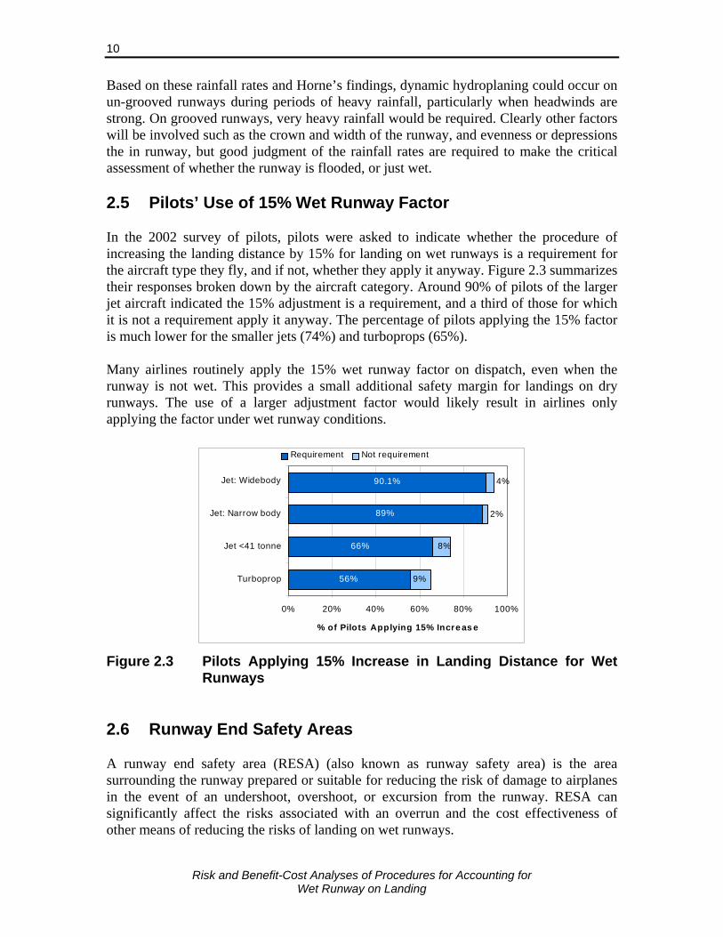
Risk and Benefit-Cost Analyses of Procedures for Accounting for
Wet Runway on Landing
10
Based on these rainfall rates and Horne’s findings, dynamic hydroplaning could occur on un-grooved runways during periods of heavy rainfall, particularly when headwinds are strong. On grooved runways, very heavy rainfall would be required. Clearly other factors will be involved such as the crown and width of the runway, and evenness or depressions the in runway, but good judgment of the rainfall rates are required to make the critical assessment of whether the runway is flooded, or just wet. 2.5 Pilots’ Use of 15% Wet Runway Factor In the 2002 survey of pilots, pilots were asked to indicate whether the procedure of increasing the landing distance by 15% for landing on wet runways is a requirement for the aircraft type they fly, and if not, whether they apply it anyway. Figure 2.3 summarizes their responses broken down by the aircraft category. Around 90% of pilots of the larger jet aircraft indicated the 15% adjustment is a requirement, and a third of those for which it is not a requirement apply it anyway. The percentage of pilots applying the 15% factor is much lower for the smaller jets (74%) and turboprops (65%). Many airlines routinely apply the 15% wet runway factor on dispatch, even when the runway is not wet. This provides a small additional safety margin for landings on dry runways. The use of a larger adjustment factor would likely result in airlines only applying the factor under wet runway conditions.
56%
66%
89%
90.1%
9%
8%
4%
2%
0% 20% 40% 60% 80% 100%
Turboprop
Jet <41 tonne
Jet: Narrow body
Jet: Widebody
% of Pilots Applying 15% Incre as e
Requirement Not requirement
Figure 2.3 Pilots Applying 15% Increase in Landing Distance for Wet Runways
2.6 Runway End Safety Areas A runway end safety area (RESA) (also known as runway safety area) is the area surrounding the runway prepared or suitable for reducing the risk of damage to airplanes in the event of an undershoot, overshoot, or excursion from the runway. RESA can significantly affect the risks associated with an overrun and the cost effectiveness of other means of reducing the risks of landing on wet runways.
Risk and Benefit-Cost Analyses of Procedures for Accounting for
Wet Runway on Landing
11
Past standards called for the RESA to extend 60 m (200 ft.) from the ends of the runway. Currently the international standard International Civil Aviation Organization (ICAO) requires a 90 m (300 ft.) RESA starting from the end of the runway strip (which itself is 60 m from the end of the runway), and recommends but not requires a 240 m RESA beyond that. In the US [10], RESA dimensions range from 120 ft. wide by 240 ft. beyond the end of the runway, to 500 ft. wide by 1,000 ft. beyond the end of the runway. Except under special conditions, the RESA standard dimensions for runways used by aircraft with approach speeds of 121 knots or more are 500 ft. wide and 1,000 ft. long. This is the RESA standard dimension for most, but not all, runways used by commercial service carriers. A RESA of 1,000 ft. is equivalent to the international ICAO recommended length of 240 m. Many runways do not meet current standards because they were constructed to meet an earlier standard. The problem is compounded by the fact that the airports are increasingly constrained by nearby land development and other natural features, such as ravines and rivers. The FAA is working towards making all significant and practicable improvements at runways used by commercial service aircraft. Runways substantially meeting RESA standards increased from approximately 46% in 1990 to 70% in 2006. According to FAA findings in 2006, only 17 of the remaining runways will not be improved because the necessary improvements are not practicable. Following the Air France A340 accident in Toronto, Transport Canada (TC) publicly stated that it will soon require all airports to build “safety areas” at the ends of runways. TC, with the participation of industry experts, is currently reviewing airport certification standards, which include RESA specifications [11]. Alternative solutions exist for runways that cannot meet the RESA standard or where the area beyond the RESA does not meet the recent ICAO recommended practice of a 240 m overrun area beyond the 60 m runway strip. The Emergency Material Arresting System (EMAS) technology is designed to stop an aircraft where it is not possible to construct a 300 m (ICAO 60 m + 240 m) or FAA 1,000 ft. overrun. This technology has demonstrated that it provides an alternative for runways where natural obstacles, such as bodies of water or sharp drop-offs, as in the case of Runway 24L in Toronto, make the construction of a standard safety area impracticable. 2.7 Frequency of Wet Runways Canada An analysis of runway surface condition reports from five airports for the years 1988-1990 was provided in the 1991 Sypher report on take-off risks on contaminated runways [12]. The report provided estimates of the average percentage of the time a section of runway is wet or contaminated, and these are summarized in Table 2.3 for wet and slippery conditions (ice, compact snow, frost and shallow depth loose snow) for the winter period from November to March. The proportion of the time the runways were

Risk and Benefit-Cost Analyses of Procedures for Accounting for
Wet Runway on Landing
12
wet during this period varied greatly by airport, but on average over the five airports, the runway was wet 12.1% of the time during winter period. Table 2.3 Average Percentage of the Time a Section of Runway is Wet or
Slippery by Contaminant Type, 1988-1990
Contaminant Type Ottawa Halifax Calgary Prince George
Edmonton Average
Wet 13.4% 17.7% 3.8% 21.6% 3.8% 12.1%Ice 7.4% 13.4% 1.9% 7.9% 8.2% 7.7%Compact Snow na 2.4% 0.7% 0.5% 1.9% 1.4%Frost 0.5% 1.4% 0.0% 0.7% 1.0% 1.0%Loose snow ≤ 1/8" 3.1% 4.8% 1.9% 6.7% 2.4% 3.8%Total During Nov-Mar 24.4% 39.8% 8.4% 37.4% 17.2% 26.0%Source: Biggs, et. al. (Sypher) 1991 [12] na – Compact snow not used as a contaminant type at Ottawa airport at that time
Runway conditions in the summer months (April to October) are not recorded on a daily basis. Runway friction measurements are taken to track rubber build—up and monitor the condition of the runway when dry, but the frequency of wet or flooded runways is not recorded. Data on the number of hours when precipitation was recorded for each airport was used to estimate the runway conditions. The percentage of the time no rain occurs during the months of April to October is presented in Table 2.4 for thirteen major airports in Canada. It is estimated that during this period the runways in Canada are wet approximately 10% of the time. Over the year it is estimated that runways in Canada are wet 11% of the time. The braking effectiveness and stopping distance are also related to the depth of water on the runway which is related to the rainfall rate. Rainfall rates over very short periods (e.g., 1, 5, 10 minutes) are not commonly collected and accurate data on the frequency of various rainfall rates and the duration of periods of heavy rainfall could not be obtained. Estimates of rainfall rate from satellite images provide some information on the occurrence of different rainfall rates, but have not been used to estimate their frequency. Hourly rainfall data was obtained from Environment Canada and was analysed to provide an approximate estimate of the frequency of various rainfall rates. This data, however, underestimates the frequency of heavy rainfall since the heavier rainfall rates typically occur for only short periods, usually less than an hour, and the clock-hour periods may contain periods of both light and heavy rainfall. Rainfall rates over short periods have been collected in some countries over a limited period (1-5 years) and methods for estimating the frequency distribution of the rainfall rate in 1-minute intervals based on hourly data have been developed [13, 14]. The method in [13] was used to convert the 60-minute rainfall rate distribution from the Environment Canada data to the 1-minute rainfall rate distribution.7 The estimated 1-minute rainfall rate distributions derived for the summer months from April to October are provided in Table 2.4 for thirteen of the 7 R1(p) = exp{ 1.071 x log[ R60(p) ] where R1(p) is the 1-minute rainfall rate (mm/h) for cumulative
probability p and R60(p) is the corresponding 60-minute rainfall rate for the same cumulative probability p.
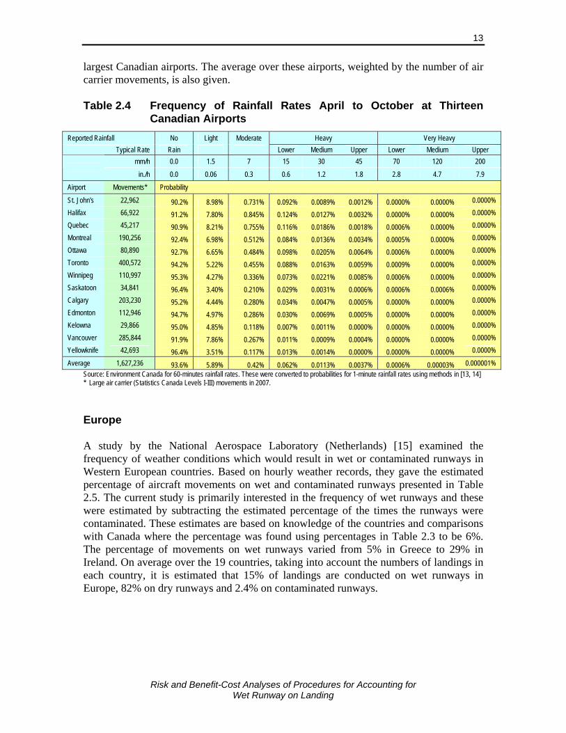
Risk and Benefit-Cost Analyses of Procedures for Accounting for
Wet Runway on Landing
13
largest Canadian airports. The average over these airports, weighted by the number of air carrier movements, is also given. Table 2.4 Frequency of Rainfall Rates April to October at Thirteen
Canadian Airports
Reported Rainfall No Light Moderate Heavy Very Heavy Typical Rate Rain Lower Medium Upper Lower Medium Upper
mm/h 0.0 1.5 7 15 30 45 70 120 200
in./h 0.0 0.06 0.3 0.6 1.2 1.8 2.8 4.7 7.9
Airport Movements* Probability
St. John's 22,962 90.2% 8.98% 0.731% 0.092% 0.0089% 0.0012% 0.0000% 0.0000% 0.0000% Halifax 66,922 91.2% 7.80% 0.845% 0.124% 0.0127% 0.0032% 0.0000% 0.0000% 0.0000% Quebec 45,217 90.9% 8.21% 0.755% 0.116% 0.0186% 0.0018% 0.0006% 0.0000% 0.0000% Montreal 190,256 92.4% 6.98% 0.512% 0.084% 0.0136% 0.0034% 0.0005% 0.0000% 0.0000% Ottawa 80,890 92.7% 6.65% 0.484% 0.098% 0.0205% 0.0064% 0.0006% 0.0000% 0.0000% Toronto 400,572 94.2% 5.22% 0.455% 0.088% 0.0163% 0.0059% 0.0009% 0.0000% 0.0000% Winnipeg 110,997 95.3% 4.27% 0.336% 0.073% 0.0221% 0.0085% 0.0006% 0.0000% 0.0000% Saskatoon 34,841 96.4% 3.40% 0.210% 0.029% 0.0031% 0.0006% 0.0006% 0.0006% 0.0000% Calgary 203,230 95.2% 4.44% 0.280% 0.034% 0.0047% 0.0005% 0.0000% 0.0000% 0.0000% Edmonton 112,946 94.7% 4.97% 0.286% 0.030% 0.0069% 0.0005% 0.0000% 0.0000% 0.0000% Kelowna 29,866 95.0% 4.85% 0.118% 0.007% 0.0011% 0.0000% 0.0000% 0.0000% 0.0000% Vancouver 285,844 91.9% 7.86% 0.267% 0.011% 0.0009% 0.0004% 0.0000% 0.0000% 0.0000% Yellowknife 42,693 96.4% 3.51% 0.117% 0.013% 0.0014% 0.0000% 0.0000% 0.0000% 0.0000%
Average 1,627,236 93.6% 5.89% 0.42% 0.062% 0.0113% 0.0037% 0.0006% 0.00003% 0.000001% Source: Environment Canada for 60-minutes rainfall rates. These were converted to probabilities for 1-minute rainfall rates using methods in [13, 14] * Large air carrier (Statistics Canada Levels I-III) movements in 2007. Europe A study by the National Aerospace Laboratory (Netherlands) [15] examined the frequency of weather conditions which would result in wet or contaminated runways in Western European countries. Based on hourly weather records, they gave the estimated percentage of aircraft movements on wet and contaminated runways presented in Table 2.5. The current study is primarily interested in the frequency of wet runways and these were estimated by subtracting the estimated percentage of the times the runways were contaminated. These estimates are based on knowledge of the countries and comparisons with Canada where the percentage was found using percentages in Table 2.3 to be 6%. The percentage of movements on wet runways varied from 5% in Greece to 29% in Ireland. On average over the 19 countries, taking into account the numbers of landings in each country, it is estimated that 15% of landings are conducted on wet runways in Europe, 82% on dry runways and 2.4% on contaminated runways.

Risk and Benefit-Cost Analyses of Procedures for Accounting for
Wet Runway on Landing
14
Table 2.5 Frequency of Runway Conditions at European Airports
Country Aircraft
Landings Wet /
Contaminated Estimated
Contaminated Estimated
Wet Dry Austria 123,772 24% 4% 20% 76%Belgium 143,351 22% 2% 20% 78%Denmark 160,431 19% 3% 16% 81%Finland 123,614 21% 5% 16% 79%France 780,890 14% 2% 12% 86%Germany 849,203 23% 5% 18% 77%Greece 145,026 5% 0% 5% 95%Ireland 94,143 29% 0% 29% 71%Italy 562,159 11% 1% 10% 89%Luxembourg 22,599 20% 4% 16% 80%Netherlands 217,137 20% 3% 17% 80%Norway 315,806 26% 5% 21% 74%Poland 56,392 19% 5% 14% 81%Portugal 100,052 9% 0% 9% 91%Spain 571,605 6% 0% 6% 94%Sweden 275,322 19% 5% 14% 81%Switzerland 254,665 20% 5% 15% 80%Turkey 250,000 12% 0% 12% 88%United Kingdom 886,949 20% 1% 19% 80%Overall 5,933,116 17.1% 2.4% 14.7% 82.9%
Notes: Aircraft include commercial jet and large turboprop (over 5,670 kg) Contaminated includes snow, ice and slush
Risk and Benefit-Cost Analyses of Procedures for Accounting for
Wet Runway on Landing
15
3. ACCOUNTING FOR WET RUNWAY IN AIRCRAFT LANDING PERFORMANCE
Current regulations of the major aviation regulatory authorities, including TC, FAA, and JAA, require information for calculating the landing performance of aircraft on a contaminated runway to be included in the AFM or supplementary guidance material for aeroplanes whose date of application for a type approval was after August 1, 1992. However, there is no such requirement for landing performance on a wet runway. The only specific operational requirement for landing when the runway is wet is that an additional factor of 15% be applied to the landing field length required. The level and appropriate use of such a factor is examined in this section. 3.1 Effects of Wet Runway on Braking The effectiveness of braking on a wet runway is reduced due to tire hydroplaning; i.e., when the rolling or sliding tire is lifted away from the pavement surface as a result of water pressures built up under the tire. There are three types of hydroplaning:8
Viscous hydroplaning – occurs at thin water depths, less than 0.3 mm. Its effect reduced on textured pavements and does not change significantly with increasing water depth (below 3 mm) and tire speed.
Dynamic hydroplaning – occurs on flooded pavements with water depths exceeding 3 mm (often more), and occurs at high speeds (dependent on tire pressure).
Reverted rubber hydroplaning – occurs when the tire fails to spin up which results in a non-rotating tire being slid over the runway surface. Poor pavement texture, high speed, wet/flooded runway and deficient braking system are all factors contributing to its occurrence.
The depths of water where dynamic hydroplaning occur depend on the surface type of the runway. A combination of viscous and dynamic hydroplaning can occur for water depths above 0.3 mm and below full dynamic hydroplaning. The effects of a wet runway on aircraft braking friction have been well documented in various studies, including Yager, Phillips and Horne [16]. Braking friction is known to be dependent on:
Surface texture of the runway, both macro and micro texture and whether the runway is grooved or un-grooved
Tread depth and type of tire Tire pressure Rubber contamination on the runway Depth of water
8 Summary of description in Wet Runway Friction: Literature and Information Review. TC Report
TP14002E by G. Comfort [8]. See Horne [6,7] for more information.

Risk and Benefit-Cost Analyses of Procedures for Accounting for
Wet Runway on Landing
16
Braking friction is far more dependent on these factors on a wet runway than a dry runway. Also, braking friction on a dry runway is fairly constant with aircraft speed, but on wet runways the friction is much less at high speeds, especially on smooth runways and/or with low tread depth tires. Thus, situations where the aircraft has higher landing ground speeds such as tailwinds and/or high loads results in a greater loss of friction and longer stopping distances. Figures 3.1 and 3.2 provides examples of the effects of tire tread and surface type on braking friction versus ground speed on a wet runway presented in Yager, Phillips and Horne [16]. The figure indicates that the braking friction at a given speed varies significantly by runway and tire type, but at 100 knots with 5-grooved tires, is around 10-20% less than on a dry runway if the runway is grooved, and 40-75% less if the runway is not grooved.
Source: Yager, Phillips and Horne [16]
Figure 3.1 Tire Tread and Grooved Runway Effects on Wet and Puddled Runways for Twin-tandem Bogie Arrangements for C-141A and 990A Aircraft

Risk and Benefit-Cost Analyses of Procedures for Accounting for
Wet Runway on Landing
17
Source: Yager, Phillips and Horne [16]
Figure 3.2 Effects of Surface Type of Braking Friction on Wet and Puddled Runways for 990A Aircraft
More recent tests [17] conducted at the FAA Tech Centre also found a large improvement in aircraft braking performance on grooved runways. As shown in Figure 3.3, the effective braking friction on a wet grooved runway with 1.5 in. spaced grooves was found to be 80% to 100% of that on a dry runway, while the corresponding values on a non-grooved runway were between 38% and 75%. The standard groove specified by the FAA is 1.5 in. spacing and ¼ in. width and depth [18]. Similar improvements were found for PFC runways. FAA test results using a 727 aircraft on two PFC runways are summarized in Figure 3.4. The effective friction on a newly installed PFC runway at Pease AFB when wet was 90% to 95% of the dry value, while at Portland International Airport, where the PFC runway had been in use for 11 years, the effective friction when wet was 70% to 80% of the dry value. The FAA states that: “The wet-to-dry stopping distance ratio on a well-maintained, grooved, wet runway is usually around 1.15 to 1. On a runway where the grooves are not maintained and rubber deposits are heavy, the stopping distance could be as high as 1.9 to 1. On un-grooved runways, the stopping distance is usually about 2 to 1.” [19] Given the results presented in Figures 3.3 and 3.4, the ratio of wet:dry stopping distances on a well maintained PFC runway would be expected be similar to that of a well maintained grooved runway.

Risk and Benefit-Cost Analyses of Procedures for Accounting for
Wet Runway on Landing
18
Source: Giesman [20]
Figure 3.3 Percentage of Dry Runway Effective Braking Friction on Wet Grooved and Un-grooved Runways for 727 and 737 Aircraft
Source: Giesman [20]
Figure 3.4 Percentage of Dry Runway Effective Braking Friction on Wet PFC Runways for 727 Aircraft
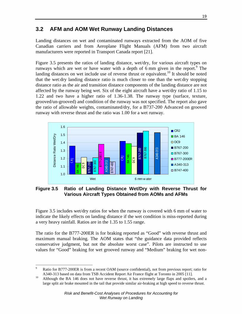
Risk and Benefit-Cost Analyses of Procedures for Accounting for
Wet Runway on Landing
19
3.2 AFM and AOM Wet Runway Landing Distances Landing distances on wet and contaminated runways extracted from the AOM of five Canadian carriers and from Aeroplane Flight Manuals (AFM) from two aircraft manufacturers were reported in Transport Canada report [21]. Figure 3.5 presents the ratios of landing distance, wet/dry, for various aircraft types on runways which are wet or have water with a depth of 6 mm given in the report.9 The landing distances on wet include use of reverse thrust or equivalent.10 It should be noted that the wet:dry landing distance ratio is much closer to one than the wet:dry stopping distance ratio as the air and transition distance components of the landing distance are not affected by the runway being wet. Six of the eight aircraft have a wet/dry ratio of 1.15 to 1.22 and two have a higher ratio of 1.36-1.38. The runway type (surface, texture, grooved/un-grooved) and condition of the runway was not specified. The report also gave the ratio of allowable weights, contaminated/dry, for a B737-200 Advanced on grooved runway with reverse thrust and the ratio was 1.00 for a wet runway.
CRJ
BA 1
46
BA 1
46
DC9 DC
9
B767
-200
B767
-200
B767
-300
B767
-300
B777
-200
ER
A340
-313
A340
-313
CRJ
B747
-400
1.0
1.1
1.2
1.3
1.4
1.5
1.6
Wet 6 mm w ater
Dis
tanc
e R
atio
Wet
/Dry
CRJ
BA 146
DC9
B767-200
B767-300
B777-200ER
A340-313
B747-400
Figure 3.5 Ratio of Landing Distance Wet/Dry with Reverse Thrust for
Various Aircraft Types Obtained from AOMs and AFMs Figure 3.5 includes wet/dry ratios for when the runway is covered with 6 mm of water to indicate the likely effects on landing distance if the wet condition is miss-reported during a very heavy rainfall. Ratios are in the 1.35 to 1.55 range. The ratio for the B777-200ER is for braking reported as “Good” with reverse thrust and maximum manual braking. The AOM states that “the guidance data provided reflects conservative judgment, but not the absolute worst case”. Pilots are instructed to use values for “Good” braking for wet grooved runway and “Medium” braking for wet non-
9 Ratio for B777-200ER is from a recent OAM (source confidential), not from previous report; ratio for
A340-313 based on data from TSB Accident Report Air France flight at Toronto in 2005 [11]. 10 Although the BA 146 does not have reverse thrust, it has extremely large flaps and spoilers, and a
large split air brake mounted in the tail that provide similar air-braking at high speed to reverse thrust.
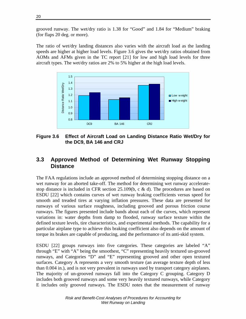
Risk and Benefit-Cost Analyses of Procedures for Accounting for
Wet Runway on Landing
20
grooved runway. The wet/dry ratio is 1.38 for “Good” and 1.84 for “Medium” braking (for flaps 20 deg. or more). The ratio of wet/dry landing distances also varies with the aircraft load as the landing speeds are higher at higher load levels. Figure 3.6 gives the wet/dry ratios obtained from AOMs and AFMs given in the TC report [21] for low and high load levels for three aircraft types. The wet/dry ratios are 2% to 5% higher at the high load levels.
0.8
0.9
1.0
1.1
1.2
1.3
1.4
1.5
DC9 BA 146 CRJ
Dis
tanc
e R
atio
Wet
/Dry
Low w eight
High w eight
Figure 3.6 Effect of Aircraft Load on Landing Distance Ratio Wet/Dry for the DC9, BA 146 and CRJ
3.3 Approved Method of Determining Wet Runway Stopping
Distance The FAA regulations include an approved method of determining stopping distance on a wet runway for an aborted take-off. The method for determining wet runway accelerate-stop distance is included in CFR section 25.109(b, c & d). The procedures are based on ESDU [22] which contains curves of wet runway braking coefficients versus speed for smooth and treaded tires at varying inflation pressures. These data are presented for runways of various surface roughness, including grooved and porous friction course runways. The figures presented include bands about each of the curves, which represent variations in: water depths from damp to flooded, runway surface texture within the defined texture levels, tire characteristics, and experimental methods. The capability for a particular airplane type to achieve this braking coefficient also depends on the amount of torque its brakes are capable of producing, and the performance of its anti-skid system. ESDU [22] groups runways into five categories. These categories are labeled “A” through “E” with “A” being the smoothest, “C” representing heavily textured un-grooved runways, and Categories “D” and “E” representing grooved and other open textured surfaces. Category A represents a very smooth texture (an average texture depth of less than 0.004 in.), and is not very prevalent in runways used by transport category airplanes. The majority of un-grooved runways fall into the Category C grouping. Category D includes both grooved runways and some very heavily textured runways, while Category E includes only grooved runways. The ESDU notes that the measurement of runway

Risk and Benefit-Cost Analyses of Procedures for Accounting for
Wet Runway on Landing
21
macro-texture is subject to uncertainty and is very dependent on experience of operators and the type of equipment used. The FAA states that “Obviously, the greater the water depth, the greater the degradation in braking capability.” The curves prescribed in Sec. 25.109(c)(1) represent a well-soaked runway, but with no significant areas of standing water, for a runway texture midway between categories B and C. The FAA included Sec. 25.109(d) to establish an optional wet runway braking coefficient for grooved or PFC runways. The braking coefficient for determining the accelerate-stop distance on grooved and PFC runways is defined in Sec. 25.109(d) as either 70 percent of the value used to determine the dry runway accelerate-stop distances, or a value based on the ESDU data. The Japanese Civil Aviation Bureau also allows a wet runway braking coefficient of 70 to 80 percent of the dry runway value to be used for grooved or PFC runways. In Japan, most of the runways at civil airports are grooved, and periodic friction surveys are conducted to assure that the surfaces are properly maintained. These methods for determining stopping distances on wet runways, both with and without reverse thrust, and on grooved and un-grooved runways, and the resulting landing wet/dry distance ratios are considered in Section 3.5. 3.4 Results of NRC Wet Runway Landing Tests The National Research Council, Canada, (NRC) conducted two series of braking performance tests using their Falcon 20 research aircraft and Bombardier DHC-8 aircraft at Montreal Mirabel, Ottawa and North Bay airports [23, 24]. Runway texture varied considerably for the four runways on which tests were conducted. Saab Friction Tester (SFT) friction values ranged from less than 0.40 to above 0.90. The study found that the Falcon 20 braking coefficients varied considerably on the different wet runway surfaces, but at a given groundspeed, correlated well with the mean SFT measured friction. The DHC-8-100 and DHC-8-400 aircraft braking coefficients were measured only on runway 11/29 at Mirabel. NRC provided the following conclusions from the tests:
The reporting of runway friction for each third of the runway length provides a better indication of areas of poor braking performance than a single runway friction value;
The aircraft braking coefficients for all three aircraft tested decreased consistently with increasing groundspeed on wet runway surfaces;
The mean values of wet runway braking coefficients for the Falcon 20 varied from 28% to 58% of the dry runway braking coefficient, depending on the surface texture;
For a given groundspeed, the Falcon 20 aircraft braking coefficients decreased with decreasing wet runway texture, correlating well with the SFT measured friction on wet runway surfaces;
The Falcon 20 and DHC-8-400 braking coefficients on wet runway 11 at Mirabel were less than the FAR 25 requirement for a fully modulating anti-skid braking system.
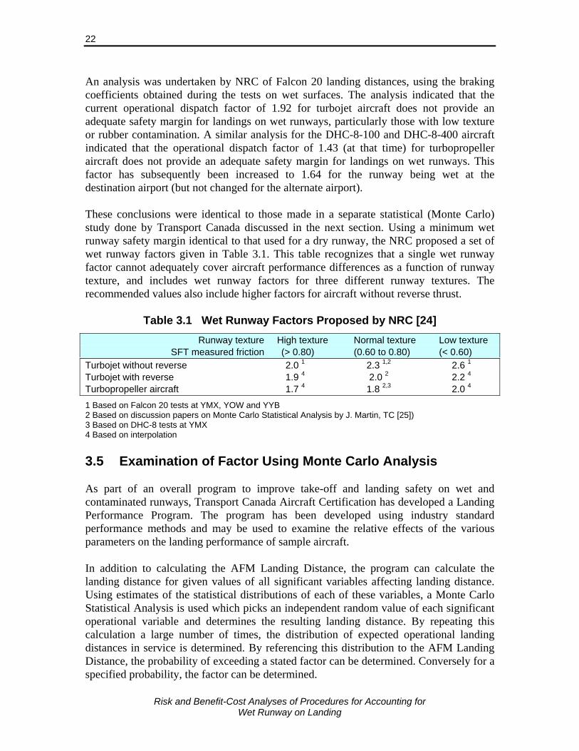
Risk and Benefit-Cost Analyses of Procedures for Accounting for
Wet Runway on Landing
22
An analysis was undertaken by NRC of Falcon 20 landing distances, using the braking coefficients obtained during the tests on wet surfaces. The analysis indicated that the current operational dispatch factor of 1.92 for turbojet aircraft does not provide an adequate safety margin for landings on wet runways, particularly those with low texture or rubber contamination. A similar analysis for the DHC-8-100 and DHC-8-400 aircraft indicated that the operational dispatch factor of 1.43 (at that time) for turbopropeller aircraft does not provide an adequate safety margin for landings on wet runways. This factor has subsequently been increased to 1.64 for the runway being wet at the destination airport (but not changed for the alternate airport). These conclusions were identical to those made in a separate statistical (Monte Carlo) study done by Transport Canada discussed in the next section. Using a minimum wet runway safety margin identical to that used for a dry runway, the NRC proposed a set of wet runway factors given in Table 3.1. This table recognizes that a single wet runway factor cannot adequately cover aircraft performance differences as a function of runway texture, and includes wet runway factors for three different runway textures. The recommended values also include higher factors for aircraft without reverse thrust.
Table 3.1 Wet Runway Factors Proposed by NRC [24]
Runway texture High texture Normal texture Low texture SFT measured friction (> 0.80) (0.60 to 0.80) (< 0.60) Turbojet without reverse 2.0 1 2.3 1,2 2.6 1 Turbojet with reverse 1.9 4 2.0 2 2.2 4 Turbopropeller aircraft 1.7 4 1.8 2,3 2.0 4
1 Based on Falcon 20 tests at YMX, YOW and YYB 2 Based on discussion papers on Monte Carlo Statistical Analysis by J. Martin, TC [25]) 3 Based on DHC-8 tests at YMX 4 Based on interpolation 3.5 Examination of Factor Using Monte Carlo Analysis As part of an overall program to improve take-off and landing safety on wet and contaminated runways, Transport Canada Aircraft Certification has developed a Landing Performance Program. The program has been developed using industry standard performance methods and may be used to examine the relative effects of the various parameters on the landing performance of sample aircraft. In addition to calculating the AFM Landing Distance, the program can calculate the landing distance for given values of all significant variables affecting landing distance. Using estimates of the statistical distributions of each of these variables, a Monte Carlo Statistical Analysis is used which picks an independent random value of each significant operational variable and determines the resulting landing distance. By repeating this calculation a large number of times, the distribution of expected operational landing distances in service is determined. By referencing this distribution to the AFM Landing Distance, the probability of exceeding a stated factor can be determined. Conversely for a specified probability, the factor can be determined.
Risk and Benefit-Cost Analyses of Procedures for Accounting for
Wet Runway on Landing
23
Monte Carlo statistical analyses have been done for a number of turbojet and turboprop aircraft by TC and are described in two reports [25, 26]. The landing distance model uses the “ESDU method” for calculating the aircraft braking coefficient and corresponds to that described in FAR 25.109 (at Amendment 92) and associated advisory material for calculating the braking component of accelerate-stop distances on wet runways (referred to in Section 3.3). The aircraft used in the studies were:
Turbojet • A - 2 engine, 50 seat regional jet, 47,000 lbf MLW, VREF at MLW = 142 KEAS • B - 2 engine, 70 seat regional jet, 67,000 lbf MLW, VREF at MLW = 136 KEAS • C - 2 engine, large business jet, 78,600 lbf MLW, VREF at MLW = 132 KEAS
Turboprop • A - 2 engines, 78 seat regional high speed turboprop, 3 approved landing flap
configurations. • B - 2 engines, 56 seat regional turboprop, 3 approved landing flap configurations. • C - 2 engines, 39 seat regional turboprop, 2 approved landing flap configurations.
All aircraft had reverse thrust (turbojet) or discing11 (turboprop) capability. The analyses presented in the two reports provide the results for these aircraft landing on runways with surface texture midway between Category B and Category C, where Category C is a heavily textured un-grooved runway. Additional Monte Carlo analyses have been conducted since these reports were published for landings on grooved runways with surface texture midway between Category D and Category E and using two additional narrow-body turbojet aircraft types [27].12 The 99% factors were calculated by dividing the predicted landing distances by the AFM Landing Distance and determining the factor at which 99% of landings distances that would be within the AFM Landing Distance multiplied by the factor. For Turboprops A, B and C, maximum landing flap, maximum landing weight, sea level, zero wind and a wet Category B/C runway, the 99% Factors were found to be 1.61, 1.81 and 1.74, respectively. This compares with the current factor of 1.64 (and 1.43 at the time of the analysis). The 99% factors for turbojet aircraft on both wet Category B/C (non-grooved) and wet Category D/E (grooved) runways are presented in Figure 3.7 where reverse thrust is not used, and Figure 3.8 for when reverse thrust is used. The values of the 99% factor over the six aircraft-configurations tested for where reverse thrust is used ranged from 1.63 to 2. 06 (median value 1.86) for Category B/C runways, and from 1.54 to 1.88 (median value 1.72) for Category D/E runways. Given the landing adjustment factor would apply
11 Discing results in a propeller blade angle giving zero or slightly positive/negative thrust at zero
airspeed. At a forward airspeed there will be drag from the propeller in this position and this drag generally increases with airspeed squared.
12 Note – the Category D/E runway could also represent the most very heavily texture runways.
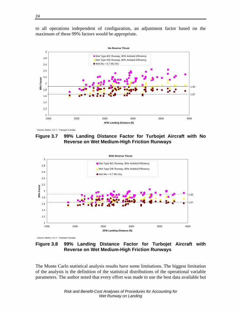
Risk and Benefit-Cost Analyses of Procedures for Accounting for
Wet Runway on Landing
24
to all operations independent of configuration, an adjustment factor based on the maximum of these 99% factors would be appropriate.
1
1.2
1.4
1.6
1.8
2
2.2
2.4
2.6
2.8
3
1500 2000 2500 3000 3500 4000
AFM Landing Distance (ft)
99%
Fac
tor
Wet Type B/C Runway, 80% Antiskid EfficiencyWet Type D/E Runway, 80% Antiskid EfficiencyWet Mu = 0.7 MU Dry
1.92
1.67
Source: Martin, J.C.T., Transport Canada
No Reverse Thrust
Figure 3.7 99% Landing Distance Factor for Turbojet Aircraft with No
Reverse on Wet Medium-High Friction Runways
1
1.2
1.4
1.6
1.8
2
2.2
2.4
2.6
2.8
3
1500 2000 2500 3000 3500 4000
AFM Landing Distance (ft)
99%
Fac
tor
Wet Type B/C Runway, 80% Antiskid Efficiency
Wet Type D/E Runway, 80% Antiskid Efficiency
Wet Mu = 0.7 MU Dry
1.92
1.67
Source: Martin, J.C.T., Transport Canada
With Reverse Thrust
Figure 3.8 99% Landing Distance Factor for Turbojet Aircraft with
Reverse on Wet Medium-High Friction Runways The Monte Carlo statistical analysis results have some limitations. The biggest limitation of the analysis is the definition of the statistical distributions of the operational variable parameters. The author noted that every effort was made to use the best data available but
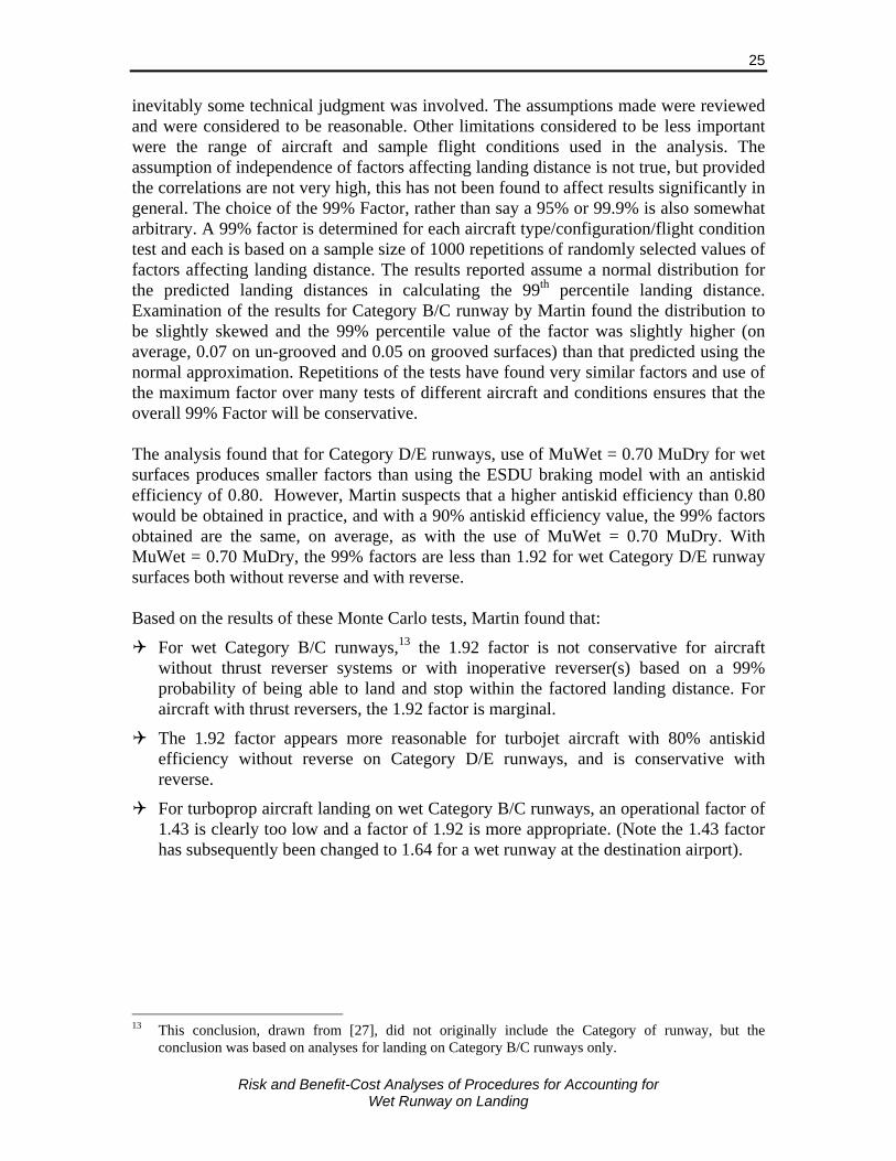
Risk and Benefit-Cost Analyses of Procedures for Accounting for
Wet Runway on Landing
25
inevitably some technical judgment was involved. The assumptions made were reviewed and were considered to be reasonable. Other limitations considered to be less important were the range of aircraft and sample flight conditions used in the analysis. The assumption of independence of factors affecting landing distance is not true, but provided the correlations are not very high, this has not been found to affect results significantly in general. The choice of the 99% Factor, rather than say a 95% or 99.9% is also somewhat arbitrary. A 99% factor is determined for each aircraft type/configuration/flight condition test and each is based on a sample size of 1000 repetitions of randomly selected values of factors affecting landing distance. The results reported assume a normal distribution for the predicted landing distances in calculating the 99th percentile landing distance. Examination of the results for Category B/C runway by Martin found the distribution to be slightly skewed and the 99% percentile value of the factor was slightly higher (on average, 0.07 on un-grooved and 0.05 on grooved surfaces) than that predicted using the normal approximation. Repetitions of the tests have found very similar factors and use of the maximum factor over many tests of different aircraft and conditions ensures that the overall 99% Factor will be conservative. The analysis found that for Category D/E runways, use of MuWet = 0.70 MuDry for wet surfaces produces smaller factors than using the ESDU braking model with an antiskid efficiency of 0.80. However, Martin suspects that a higher antiskid efficiency than 0.80 would be obtained in practice, and with a 90% antiskid efficiency value, the 99% factors obtained are the same, on average, as with the use of MuWet = 0.70 MuDry. With MuWet = 0.70 MuDry, the 99% factors are less than 1.92 for wet Category D/E runway surfaces both without reverse and with reverse. Based on the results of these Monte Carlo tests, Martin found that:
For wet Category B/C runways,13 the 1.92 factor is not conservative for aircraft without thrust reverser systems or with inoperative reverser(s) based on a 99% probability of being able to land and stop within the factored landing distance. For aircraft with thrust reversers, the 1.92 factor is marginal.
The 1.92 factor appears more reasonable for turbojet aircraft with 80% antiskid efficiency without reverse on Category D/E runways, and is conservative with reverse.
For turboprop aircraft landing on wet Category B/C runways, an operational factor of 1.43 is clearly too low and a factor of 1.92 is more appropriate. (Note the 1.43 factor has subsequently been changed to 1.64 for a wet runway at the destination airport).
13 This conclusion, drawn from [27], did not originally include the Category of runway, but the
conclusion was based on analyses for landing on Category B/C runways only.
Risk and Benefit-Cost Analyses of Procedures for Accounting for
Wet Runway on Landing
26
3.6 Factor with Allowance for Reverse Thrust A weakness with the current adjustment factor for wet runways is that it applies to all aircraft independent of whether jet aircraft have reverse thrust capability, or turboprop aircraft have discing capability. Reverse thrust or discing have only a small effect on landing distance on dry runways and are not accounted for in the landing field requirements. However, their effect can be very significant on wet and contaminated runways when braking friction is low. Current regulations allow performance calculations to account for their use in determining accelerate-stop distances for take-offs from wet and contaminated runways, and landing distances on contaminated runways. The effect of reverse thrust on wet runway landing distance is primarily dependent on the effectiveness of the tire braking, and reverse thrust systems which varies with aircraft type and runway condition. Also, reverse thrust cannot always be used to its maximum due to constraints such as controllability of aircraft with a crosswind. Results on the effectiveness of reverse thrust when landing on a wet runway from various sources are summarized below:
Transport Canada Landing performance program, described earlier, models the effect of reverse thrust on landing distance and used conservative thrust reverse data in the analysis. The effect of reverse thrust was determined using the mean of the difference in wet landing distance with and without reverse thrust using results of the Monte Carlo test runs over the different aircraft types, configurations and conditions. The average effect of not having reverse thrust on a wet runway landing distance was as follows: • Category B/C (un-grooved) runway 10.5% increase • Category D/E (grooved) runway, 80% antiskid efficiency 6.6% increase • Category D/E (grooved) runway, 90% antiskid efficiency 4.9% increase
The wet/dry landing distance ratio for a B747-400 for no, partial and full use of reverse thrust when landing on a wet runway obtained from an AOM are presented in Figure 3.9 [20]. With full reverse the landing distance ratio is close to the 15% wet runway dispatch adjustment factor, but the landing distance increases by 21.6% [(1.41-1.16)/1.16] when reverse thrust is not used.
The decrease in landing distance due to use of reverse thrust for an A340-313 aircraft is approximately 8% based on distances given in [11].
The Flight Safety Foundation gives the following typical values for the effect of reverse thrust on landing distance (variation depending on type of braking used – manual or autoland) [2]: • Dry runway 0% to 7% decrease on dry runway landing distance • Wet runway 5% to 12% decrease on wet runway landing distance • Water 6 - 12 mm 12% to 18% decrease on water (6 - 12 mm) contaminated
runway landing distance

Risk and Benefit-Cost Analyses of Procedures for Accounting for
Wet Runway on Landing
27
The type of runway – grooved/un-grooved, medium/high texture was not specified. Note that percentages are slightly higher than these when considering the increase in landing distance due to the unavailability of reverse thrust.14
1.16
1.26
1.41
0.8
0.9
1.0
1.1
1.2
1.3
1.4
1.5
Full Reverse Thrust 2 Engine ReverseThrust
No Reverse Thrust
Dis
tanc
e R
atio
Wet
/Dry
B747-400
Figure 3.9 Effect of Reverse Thrust on Landing Distance Ratio Wet/Dry for B747-400 for AOM
Based on these results, the effect of not using reverse thrust on a wet runway would typically be to increase the wet runway landing distance by about 11% on a Category B/C runway, and by 6% on a Category D/E runway. This corresponds to an increase in the landing field distance factor (currently 1.92 for jet aircraft) of 0.17 for aircraft without reverse thrust on Category B/C runways, and by 0.09 on Category D/E runways. 3.7 Factor with Allowance for Runway Type and Condition The runway surface texture, type of material, and grooving all have significant effects on stopping distance. In addition, the condition of the runway, including both the presence of rubber contamination and the degradation of the texture and grooving, also has a significant impact. While TC, the FAA and other authorities have standards for constructing and maintaining runways, with few exceptions, regulations do not allow the properties of the runway to be accounted for in determining aircraft stopping distances. This lack of accountability is due to the range of surface types and conditions to be considered and the lack of widely acceptable means of measuring these properties. Instead, minimal acceptable standards have been set and performance and safety factors set based on the aircraft performance on runways meeting these minimum standards. These standards and practices vary by country and can vary within the country where they are only recommended practices. On exception is the allowance for improved braking performance on wet runways with grooved or PFC surfaces in determining accelerate-stop distances. As described in Section 3.3, the FAA allow the ESDU method to be used to determined the braking 14 As the difference is divided by the landing distance with reverse thrust which is less than the landing
distance without reverse thrust.
Risk and Benefit-Cost Analyses of Procedures for Accounting for
Wet Runway on Landing
28
performance on a wet grooved or PFC runway, or a simple factor of Mu(wet) = 70% Mu(dry) can be used. The FAA include the condition that “These accelerate-stop distances apply only to runways that are grooved or treated with PFC overlay that the operator has determined have been designed, constructed, and maintained in a manner acceptable to the FAA Administrator”. The Japanese Civil Aviation Bureau also allows a wet runway braking coefficient of 70 to 80 percent of the dry runway value to be used for grooved or PFC runways. Improvements in aircraft braking on wet runways with various surface types were discussed in Section 3.1. Stopping distance is only one component of the landing distance, the others, as discussed by Martin [25, 26] and Croll [23], are the air distance and transition distance. Percentage reductions in landing distance through improved braking are less than the percentage reduction in stopping distance. The effects of surface types on landing distance and the factors to maintain safety margins equivalent to dry runways are considered below. Attention is focused on the surface type which is known to reduce stopping distance in wet conditions and which has already been accounted for in the regulations of major aviation authorities; i.e., grooved or PFC runways. The analysis of the Falcon 20 tests by NRC [23] estimated wet runway factors for the Falcon 20 aircraft on an un-grooved runway. These results were further analysed to estimate what the factors would have been for landing on a wet grooved runway. The analysis, given in Appendix B, uses the FAA’s approved factor of braking Mu on wet runway equaling 70% of that on a dry runway. Table 3.2 gives the factored landing distance on dry, equivalent to the landing field length required, and the excess above the AFM landing distance (calculated by subtraction).15 This excess is the safety margin and is determined from the AFM and factored landing distance (on dry). This excess is added to the landing distance on a wet runway and the total is divided by the AFM landing distance to estimate the factor required to maintain the same safety margin on a wet runway. The factor varies from 2.19 to 2.44 for a wet un-grooved runway, and from 1.86 to 1.90 for a wet grooved runway. This compares with the current factor of 1.92 for wet runways applied at the time of dispatch. The stopping distance wet:dry(AFM) ratio for the Falcon 20 ranges from approximately 2.2-2.4 to 1.0.16 This is a little higher than the wet-to-dry stopping distance ratio on a well-maintained, wet, un-grooved runway of close to 2.0 to 1 indicated by the FAA (see Section 3.1). If reverse thrust had been available on the aircraft the landing distance would have been reduced by about 11%, or by 6% on a grooved runway, based on the findings of the previous section. This would bring the wet/dry ratio to about 1.9-2.1 to 1, similar to the value given by the FAA. Applying the wet:dry stopping distance ratio of 1.15 to 1 for a grooved runway to the Falcon 20 distances would result in a reduction of at least 25% in the wet landing distance due to grooving of the runway. The factor for the wet runway landing distance on a grooved runway would then be 1.75 to 1.85 with allowance for reverse thrust, both less than the current factor of 1.92. 15 Note that distances are from Croll and Bastian differ slightly from the AFM landing distance / 0.6 due
to rounding. 16 From Table C1, Appendix C, ratio of stopping distances is D3(wet) / D3(dry).
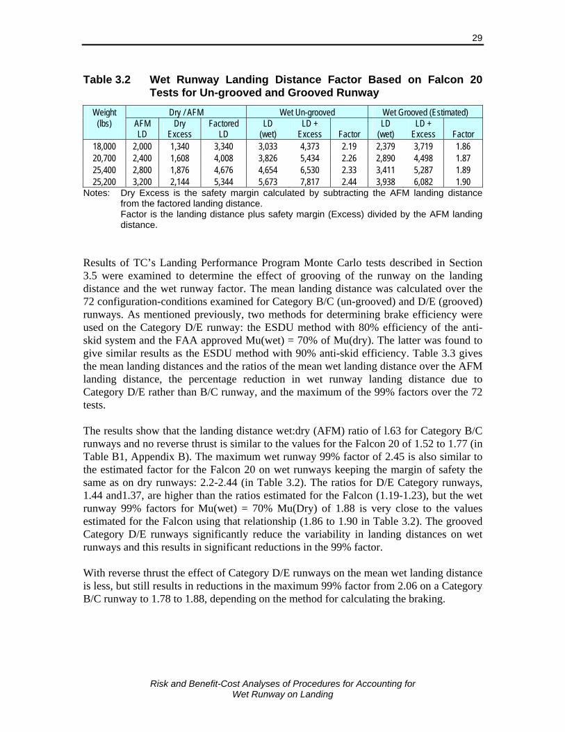
Risk and Benefit-Cost Analyses of Procedures for Accounting for
Wet Runway on Landing
29
Table 3.2 Wet Runway Landing Distance Factor Based on Falcon 20
Tests for Un-grooved and Grooved Runway
Weight Dry / AFM Wet Un-grooved Wet Grooved (Estimated) (lbs)
AFM LD
Dry Excess
Factored LD
LD (wet)
LD + Excess Factor
LD (wet)
LD + Excess Factor
18,000 2,000 1,340 3,340 3,033 4,373 2.19 2,379 3,719 1.86 20,700 2,400 1,608 4,008 3,826 5,434 2.26 2,890 4,498 1.87 25,400 2,800 1,876 4,676 4,654 6,530 2.33 3,411 5,287 1.89 25,200 3,200 2,144 5,344 5,673 7,817 2.44 3,938 6,082 1.90
Notes: Dry Excess is the safety margin calculated by subtracting the AFM landing distance from the factored landing distance.
Factor is the landing distance plus safety margin (Excess) divided by the AFM landing distance.
Results of TC’s Landing Performance Program Monte Carlo tests described in Section 3.5 were examined to determine the effect of grooving of the runway on the landing distance and the wet runway factor. The mean landing distance was calculated over the 72 configuration-conditions examined for Category B/C (un-grooved) and D/E (grooved) runways. As mentioned previously, two methods for determining brake efficiency were used on the Category D/E runway: the ESDU method with 80% efficiency of the anti-skid system and the FAA approved Mu(wet) = 70% of Mu(dry). The latter was found to give similar results as the ESDU method with 90% anti-skid efficiency. Table 3.3 gives the mean landing distances and the ratios of the mean wet landing distance over the AFM landing distance, the percentage reduction in wet runway landing distance due to Category D/E rather than B/C runway, and the maximum of the 99% factors over the 72 tests. The results show that the landing distance wet:dry (AFM) ratio of l.63 for Category B/C runways and no reverse thrust is similar to the values for the Falcon 20 of 1.52 to 1.77 (in Table B1, Appendix B). The maximum wet runway 99% factor of 2.45 is also similar to the estimated factor for the Falcon 20 on wet runways keeping the margin of safety the same as on dry runways: 2.2-2.44 (in Table 3.2). The ratios for D/E Category runways, 1.44 and1.37, are higher than the ratios estimated for the Falcon (1.19-1.23), but the wet runway 99% factors for Mu(wet) = 70% Mu(Dry) of 1.88 is very close to the values estimated for the Falcon using that relationship (1.86 to 1.90 in Table 3.2). The grooved Category D/E runways significantly reduce the variability in landing distances on wet runways and this results in significant reductions in the 99% factor. With reverse thrust the effect of Category D/E runways on the mean wet landing distance is less, but still results in reductions in the maximum 99% factor from 2.06 on a Category B/C runway to 1.78 to 1.88, depending on the method for calculating the braking.

Risk and Benefit-Cost Analyses of Procedures for Accounting for
Wet Runway on Landing
30
Table 3.3 Results of TC Landing Performance Program Monte Carlo Tests on Category B/C and D/E Runways
Runway Braking No Reverse Thrust Reverse Thrust Surface Category
Mean Wet
LD (ft)
LD Wet:Dry (AFM)
Effect of D/E runway
Max 99%
Factor
Mean Wet LD
(ft)
LD Wet:Dry (AFM)
Effect of D/E runway
Max 99%
Factor
B/C 80% antiskid efficiency
4,636 1.63 n.a. 2.45 4,196 1.47 n.a. 2.06
D/E 80% antiskid efficiency
4,109 1.44 -11% 2.14 3,855 1.35 -8% 1.88
D/E Mu(wet) = 70% Mu(Dry) 3,914 1.37 -16% 1.88 3,732 1.31 -11% 1.78
Notes: Category B/C runway mid way between B (medium texture) and C (high texture) runway, un-grooved. Category D/E runway mid way between D (medium texture) and E (high texture) runway, grooved. AFM landing distance is the same for the 3 runway/braking cases and with and without reverse thrust. Mean
LD over all landing configurations tested was 2,848 ft. Effect of D/E runway is the percentage reduction in Mean landing distance from Category B/C runway Maximum 99% factors were 0.05-0.07 higher when based on 99th percentile, rather than an assumed normal
distribution. Source: Mean and AFM LD and 99% factors from Martin, 2007, to be published in Discussion Paper 24. 3.8 Summary The wet runway factors proposed by NRC and presented in Table 3.1 are reasonable and consistent with other published literature and the latest models of stopping on wet runways. The proposed approach has several drawbacks which will make it very difficult to implement in practice, especially internationally. These include:
The classification and measurement of High, Normal and Low texture runways; and
The exclusion of grooving of runways or PFC as surface types with improved braking in wet conditions.
Croll proposed that runway texture be classified as determined by SFT friction measurements in self-wetting mode and suggested values to be used. This approach is feasible in Canada where the SFT is used to monitor surface condition and measure braking friction on wet runways (but not with winter runway contamination), although the frequency and coverage may need to be increased. More frequent testing may be required to ensure rubber build-up on the runway has not reduced the SFT value and changed the category of texture for the runway. Friction monitoring procedures in other countries vary greatly and it would be very difficult to come to a universally accepted method of classifying surface texture based on runway friction monitoring tests. Alternative methods of classifying texture could possibly be used, but would have to correlate well with aircraft braking performance, as the SFT method does. Procedures exist for measuring the macro-texture of the runway which could be universally applied, but aircraft braking performance is also dependent on the micro texture which is more

Risk and Benefit-Cost Analyses of Procedures for Accounting for
Wet Runway on Landing
31
difficult to determine. Allowance for rubber deposits on the surface would also have to be made. The current wet runway landing factor of 1.92 for jet aircraft have been adequate for landings of most jet aircraft in most of the major aviation countries as most jets have reverse thrust capability and most of these countries have grooved runways. In these situations the Falcon tests and other research indicates the 1.92 factor provides a similar safety margin as on dry runways. Countries which have grooved their runways at airports with significant passenger traffic include the US, UK, Australia, much of Europe (including Germany, Poland, Spain and Cyprus, among others), Japan, Hong Kong, Malaysia, Cayman, St Lucia, Barbados, Kenya, and Ghana. This list is by no means complete. These countries would want to ensure credit is given for their grooved runways in any internationally recognized requirements. Grooving of the runway does not necessary result in high SFT friction measurements in self-wetting mode17 as the SFT value tends to be more related to the macro and micro texture of the pavement. For example, Munich airport has a grooved runway and recent SFT tests found a value less than 0.8. Thus, well maintained grooved runways may not be classified by Croll’s proposal as “High Texture” runways. An alternative approach to that proposed by Croll for classifying runway surfaces would be to use the approach used by the FAA in allowing for surface type in determining wet runway accelerate-stop distance. The FAA essentially classifies the runway as: Grooved/PFC, or Other, and allows the improved braking on grooved and PFC runways to be accounted for when applicable. As with non-grooved/non-PFC runways, the condition of the grooved or PFC runway must meet certain criteria for credit to be given. Suggested factors for this runway surface type classification are:
Grooved/PFC Other
Jet without reverse thrust 2.00 2.45
Jet with reverse thrust 1.92 2.10
Turbopropeller aircraft 1.64 1.90 The factors for grooved/PFC are very close to those proposed by Croll for High texture runways and the values for jets with reverse thrust are consistent with current wet runway dispatch factors. The values for jet aircraft on “Other” runway surfaces are based on the maximum 99% factor found in the Monte Carlo tests which are between the “Normal” and “Low” texture runway values from Croll. The value for turboprops of 1.9 is mid-way between Croll’s values for “Normal” and “Low” texture runways. This approach to accounting for runway surface type is likely easier to implement in practice, especially internationally, although it still does not allow for the improved braking performance of well maintained, clean, very high texture runways. The factors for non-grooved/non-PFC runways fall between Croll’s “Normal” and “Low Texture” 17 Personal communication with Mahmoud Farha, Transport Canada, Aerodromes, Standards.
Risk and Benefit-Cost Analyses of Procedures for Accounting for
Wet Runway on Landing
32
runways are therefore likely conservative for the majority of landings. This is consistent with the use of the mid-point for braking between Category B and Category C runways used in determining accelerate-stop distances. Inclusion of runway surface type specifically in the aircraft landing performance calculation and providing operational benefits for the safest types will encourage the greater use of those surface types.
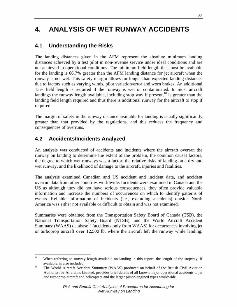
Risk and Benefit-Cost Analyses of Procedures for Accounting for
Wet Runway on Landing
33
4. ANALYSIS OF WET RUNWAY ACCIDENTS 4.1 Understanding the Risks The landing distances given in the AFM represent the absolute minimum landing distances achieved by a test pilot in non-revenue service under ideal conditions and are not achieved in operational conditions. The minimum field length that must be available for the landing is 66.7% greater than the AFM landing distance for jet aircraft when the runway is not wet. This safety margin allows for longer than expected landing distances due to factors such as varying winds, pilot variation/error and worn brakes. An additional 15% field length is required if the runway is wet or contaminated. In most aircraft landings the runway length available, including stop-way if present,18 is greater than the landing field length required and thus there is additional runway for the aircraft to stop if required. The margin of safety in the runway distance available for landing is usually significantly greater than that provided by the regulations, and this reduces the frequency and consequences of overruns. 4.2 Accidents/Incidents Analyzed An analysis was conducted of accidents and incidents where the aircraft overran the runway on landing to determine the extent of the problem, the common causal factors, the degree to which wet runways was a factor, the relative risks of landing on a dry and wet runway, and the likelihood of damage to the aircraft, injuries and fatalities. The analysis examined Canadian and US accident and incident data, and accident overrun data from other countries worldwide. Incidents were examined in Canada and the US as although they did not have serious consequences, they often provide valuable information and increase the numbers of occurrences on which to identify patterns of events. Reliable information of incidents (i.e., excluding accidents) outside North America was either not available or difficult to obtain and was not examined. Summaries were obtained from the Transportation Safety Board of Canada (TSB), the National Transportation Safety Board (NTSB), and the World Aircraft Accident Summary (WAAS) database19 (accidents only from WAAS) for occurrences involving jet or turboprop aircraft over 12,500 lb. where the aircraft left the runway while landing.
18 When referring to runway length available on landing in this report, the length of the stopway, if
available, is also included. 19 The World Aircraft Accident Summary (WAAS) produced on behalf of the British Civil Aviation
Authority, by Airclaims Limited, provides brief details of all known major operational accidents to jet and turboprop aircraft and helicopters and the larger piston-engined types worldwide.

Risk and Benefit-Cost Analyses of Procedures for Accounting for
Wet Runway on Landing
34
Occurrences over the 17-year period 1990-2007 were examined.20 The worldwide accidents data obtained from the WAAS database included commercial aircraft operations only. Additional information was obtained from the Flight Safety Foundation accident database, accident reports and newspaper articles on the accidents/incidents. The following criteria were used to exclude overrun occurrences from consideration as they were not considered relevant:
Aircraft did not touch down on the runway;
Rejected landings resulting in aircraft overrunning the runway
Flights of military and government aircraft;
Flights where the aircraft was being tested (e.g., after maintenance);
Emergency or forced landings, or terrorism;
Collision with other aircraft or vehicles;
Landings on gravel runways;
Training flights; and
Aircraft went off the side of the runway, except in Canada where all accidents on the TSB database involving jet aircraft that left the runway while landing were examined.
The occurrence summaries included date, location, operator, aircraft make/model, a categorization and description of the event(s) leading to the occurrence, the phase of flight, injuries, and a qualitative description of the occurrence, although not all fields were complete. In addition to the occurrences where the aircraft overran the runway on landing, there are a number of occurrences where the aircraft left the side of the runway and sometimes went beyond the end of the runway. Some of these accidents are similar to overrun accidents and may have been prevented by accounting for wet runways in determining landing distances. In others, factors other than stopping distance led to the occurrence. An example is crosswind, which can cause the aircraft to drift sideward, particularly on slippery runways. The analysis focused on overruns, but the relative risk of “off-side of runway” occurrences on wet runways was also considered using the Canadian database. Occurrences were not selected based on runway condition, but runway condition was examined to determine whether it was a factor in the accident/incident and to determine the relative risks on wet and dry runways. The runway condition fields in the incident reports are rarely completed and the runway condition had to be inferred from the weather conditions, event category and description, and from the qualitative summary.
20 For Canada: Incident data was available in the current detailed format back to 1989 and 1989 was
used as the start of the data period. Data was obtained for occurrences for up to March 2007 and only these were used in the analysis.
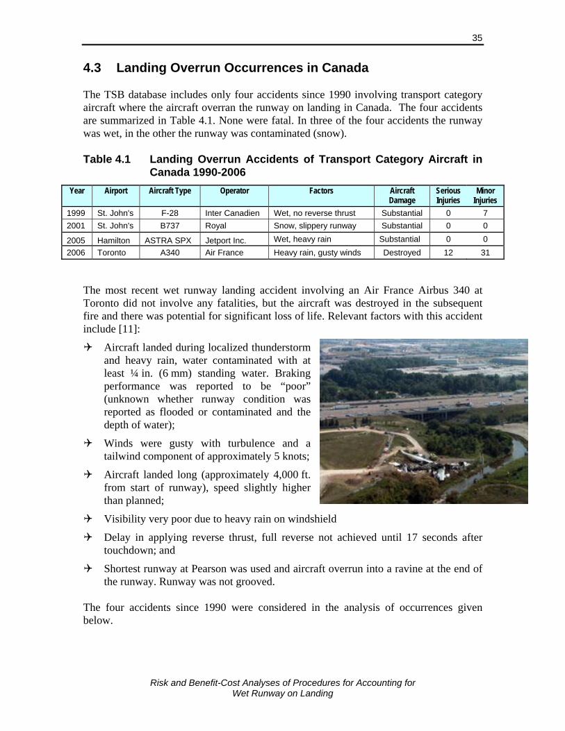
Risk and Benefit-Cost Analyses of Procedures for Accounting for
Wet Runway on Landing
35
4.3 Landing Overrun Occurrences in Canada The TSB database includes only four accidents since 1990 involving transport category aircraft where the aircraft overran the runway on landing in Canada. The four accidents are summarized in Table 4.1. None were fatal. In three of the four accidents the runway was wet, in the other the runway was contaminated (snow). Table 4.1 Landing Overrun Accidents of Transport Category Aircraft in
Canada 1990-2006
Year Airport Aircraft Type Operator Factors Aircraft Damage
Serious Injuries
Minor Injuries
1999 St. John's F-28 Inter Canadien Wet, no reverse thrust Substantial 0 7 2001 St. John's B737 Royal Snow, slippery runway Substantial 0 0
2005 Hamilton ASTRA SPX Jetport Inc. Wet, heavy rain Substantial 0 0 2006 Toronto A340 Air France Heavy rain, gusty winds Destroyed 12 31
The most recent wet runway landing accident involving an Air France Airbus 340 at Toronto did not involve any fatalities, but the aircraft was destroyed in the subsequent fire and there was potential for significant loss of life. Relevant factors with this accident include [11]:
Aircraft landed during localized thunderstorm and heavy rain, water contaminated with at least ¼ in. (6 mm) standing water. Braking performance was reported to be “poor” (unknown whether runway condition was reported as flooded or contaminated and the depth of water);
Winds were gusty with turbulence and a tailwind component of approximately 5 knots;
Aircraft landed long (approximately 4,000 ft. from start of runway), speed slightly higher than planned;
Visibility very poor due to heavy rain on windshield
Delay in applying reverse thrust, full reverse not achieved until 17 seconds after touchdown; and
Shortest runway at Pearson was used and aircraft overrun into a ravine at the end of the runway. Runway was not grooved.
The four accidents since 1990 were considered in the analysis of occurrences given below.
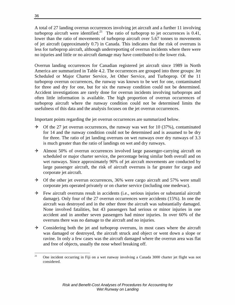
Risk and Benefit-Cost Analyses of Procedures for Accounting for
Wet Runway on Landing
36
A total of 27 landing overrun occurrences involving jet aircraft and a further 11 involving turboprop aircraft were identified.21 The ratio of turboprop to jet occurrences is 0.41, lower than the ratio of movements of turboprop aircraft over 5.67 tonnes to movements of jet aircraft (approximately 0.7) in Canada. This indicates that the risk of overruns is less for turboprop aircraft, although underreporting of overrun incidents where there were no injuries and little or no aircraft damage may have contributed to the lower risk. Overrun landing occurrences for Canadian registered jet aircraft since 1989 in North America are summarized in Table 4.2. The occurrences are grouped into three groups: Jet Scheduled or Major Charter Service, Jet Other Service, and Turboprop. Of the 11 turboprop overrun occurrences, the runway was known to be wet for one, contaminated for three and dry for one, but for six the runway condition could not be determined. Accident investigations are rarely done for overrun incidents involving turboprops and often little information is available. The high proportion of overrun occurrences of turboprop aircraft where the runway condition could not be determined limits the usefulness of this data and the analysis focuses on the jet overrun occurrences. Important points regarding the jet overrun occurrences are summarized below.
Of the 27 jet overrun occurrences, the runway was wet for 10 (37%), contaminated for 14 and the runway condition could not be determined and is assumed to be dry for three. The ratio of jet landing overruns on wet runways over dry runways of 3.3 is much greater than the ratio of landings on wet and dry runways.
Almost 50% of overrun occurrences involved large passenger-carrying aircraft on scheduled or major charter service, the percentage being similar both overall and on wet runways. Since approximately 90% of jet aircraft movements are conducted by large passenger aircraft, the risk of aircraft overruns is far greater for cargo and corporate jet aircraft.
Of the other jet overrun occurrences, 36% were cargo aircraft and 57% were small corporate jets operated privately or on charter service (including one medevac).
Few aircraft overruns result in accidents (i.e., serious injuries or substantial aircraft damage). Only four of the 27 overrun occurrences were accidents (15%). In one the aircraft was destroyed and in the other three the aircraft was substantially damaged. None involved fatalities, but 43 passengers had serious or minor injuries in one accident and in another seven passengers had minor injuries. In over 60% of the overruns there was no damage to the aircraft and no injuries.
Considering both the jet and turboprop overruns, in most cases where the aircraft was damaged or destroyed, the aircraft struck and object or went down a slope or ravine. In only a few cases was the aircraft damaged where the overrun area was flat and free of objects, usually the nose wheel breaking off.
21 One incident occurring in Fiji on a wet runway involving a Canada 3000 charter jet flight was not
considered.

Risk and Benefit-Cost Analyses of Procedures for Accounting for
Wet Runway on Landing
37
Table 4.2 Summary of Occurrences in Canada on Landing where the Aircraft Overran the Runway
Year AirportAircraft
Type OperatorService
TypeOver-run ft Runway Condition Factors
Aircraft Damage
Minor injuries Terrain/ Hit
Overrun - Jet - Scheduled/Major Charter Service1989 Saskatoon B737 Canadian Scheduled 10 Wet Landed long Very minor 01990 Gander DC-8 Rosenbalm Aviation M.Charter 350 Snow None 01990 Quebec DC-8 Nationair M.Charter 300 Snow, slush, CRFI used 0.38, est. 0.3 Landed long (2600 ft) None 01990 Deer Lake BAE 146 Air Nova Scheduled 30 Slippery None 0 Flat1994 Terrace BAE 146 Air BC Scheduled 300 Ice & slush None 01994 Ottawa A320 Air Canada Scheduled Long landing (4000 ft) High and fast None 01995 St. John's B727 Royal Aviation Scheduled 300 Wet Landed long. Excess speed(18kt) . Poor visibility Minor 01999 St. John's F-28 Inter Canadien Scheduled 420 Wet No rev thrust Braking ineffective Substantial 7 Concrete slabs1999 Terrace BAE 146 Air BC Scheduled 400 Landed long (3000 ft) Windshear None 01999 Sandspit F-28 Canadian Scheduled 200 100% snow covered, reported CRFI =.53 No rev thrust None 0 Stopway2000 Montreal Dorval B747-400 Royal Air Marco Scheduled 700 Wet Rubber accumulation Incorrect brake setting None 0 Closed part of runway2000 Fredericton F-28 Canadian Scheduled 300 50%B&D 50% thin slush 1/4" Speed high No rev thrust Minor 02006 Toronto A340 Air France Scheduled 600 Wet Landed long, gusty winds, heavy rain Destroyed 12 ser. Ravine
Overrun - Jet - Other Services1995 Sherbrooke LR35 Sky Service Charter 75 Just cleared, thin coat snow last 1000' No rev thrust None 0 Deep snow 26"1995 Detroit City US LR55 Leased Private 50 Ice covered on last 1000' No rev thrust Minor 0 Hit picket fence1996 Moncton B727 Kelowna Flight Craft Cargo 154 100% Slush 0-1/2" with ice under
slush at ruway endLanded long (1850 ft) Not full rev thrust used None 0 Flat
1998 Peterborough Falcon 20 Reliant Airlines Charter No rev thrust Minor 01998 Mackenzie LR35 Canada Jet Charters Charter 10 Slush light layer No rev thrust. Drag chute not deployed None 02000 Ottawa B727 Miami Air Intern'l Cargo 200 Wet Excessive speed (30kt) Landed long None 02001 St. John's B737 Royal Airlines Cargo 20 Light & blowing snow Landed long Excessive speed Substantial 0 Deep snow2001 Gander B747-200 Evergreen Intern'l Cargo 5 Rough ice, snow Rev thrust used incorrectly None 02001 Sarnia MU-300 Seagrave Aviation Charter 150 Wet Gusty winds None 02002 Gander DC-8-63 Arrow Air Cargo 100 Wet High speed, landed long, Incorrect tailwind factor None 0 Closed runway2004 Sherbrooke Falcon 20 USA Jet Airlines Charter 75 70% ice/snow None 02005 Hamilton ASTRA SPXJetport Inc. Charter 122 Wet Landed long Moderate rainfall Substantial 0 Downslope2006 Hamilton B707-300 Principal Air Charter 10 Wet Heavy rain None 02007 Prince George LR25B L&C Coastal Medevac 60 70% traces wet snow, 30% damp Downslope runway Minor 0
Overrun - Turboprops1990 Moncton Merlin IV Jetall Private 20 Brake malfuncation None 0 Flat1993 Tofino CV440 Canair Cargo Cargo 150 Substantial 0 Struck object1993 Big Sand Lake HS748 Air Manitoba Combi long Landed long High speed Substantial 0 Embankment & scrub trees1995 Jasper MU-300 Lignum Private Tailwind Tubulance Substantial 01998 Kasabonika HS748 Wasaya Cargo 450 Brake malfunction (?) Destroyed 3 Steep incline with large rocks1996 Quebec Metro III Air Montreal Scheduled 250 Wet, water (hydroplaning) Landed long Light rainfall & fog None 01999 Dryden Metro III Bearskin Lake Scheduled 300 CRFI 0.37-0.35, heavy frost Landed long (3000 ft) Minor 01999 Victoria DHC-8 Canadian Scheduled 10 100% B&D Brake malfunction (?) None 02000 Windsor AN-124 Antonov Design BureaCargo 340 75% snow 1", 25% ice patches Landed long Minor 0 Fence2004 Oshawa SD3-60 Air Cargo Carriers Cargo 1500 Snow covered Rejected landing Poor visibility Substantial 2 ser. Fence, forestation2005 Chapleau, ON G-159 Propair Cargo 10 Brake malfuction None 0
Note: Landings on wet runway highlighted in yellow, runways with snow/ice contamination are highlighted in blue, Accidents are bolded. * 12 serious injuries

Risk and Benefit-Cost Analyses of Procedures for Accounting for
Wet Runway on Landing
38
There were three occurrences where the aircraft left the side of the runway and the runway was wet. In one of these occurrences the runway was flooded and hydroplaning occurred, and in another heavy rain was falling. Measures to reduce the risk of overruns on wet runways will address most (77%) of the occurrences on wet runways.
Overrun distances in these occurrences varied from 10 to 1500 ft. as illustrated in Figure 4.1. Surprisingly, overrun distances tended to be greater for occurrences on wet runways than on contaminated runways. The average overrun distances were 260 ft. on wet runways and 238 ft. on contaminated runways. The average overrun distance for the six occurrences where the runway condition could not be determined was 173 ft.
0%
5%
10%
15%
20%
25%
30%
35%
0 - 50 51 - 150 151 - 250 251 - 350 351 - 450 Over 450
Overrun Distance (feet)
% o
f Occ
urre
nces
Wet
Contaminated
Source: TSB Aviation Occurrence Database, 1989-March 2007
Figure 4.1 Distribution of Overrun Distances for Occurrences where Canadian Jet Aircraft Overran Runway 1989-March 2007
Of the 33 occurrences where the aircraft ran off the side of the runway (not shown in table), the runway was reported as wet in only three (9%) occurrences. Crosswinds or gusty winds are more likely to be a factor in these “off-the-side of runway” occurrences. For these types of occurrences, the runway was more frequently wet or contaminated for large jet aircraft than for smaller aircraft. There were no injuries in any of these 33 occurrences and in only three was the aircraft substantially damaged (none of the three when runway was wet). Detailed investigations are conducted for few occurrences and most reports do not include the factors that led up to the event. The category event description and the qualitative summary usually provide some indication of these factors and they were used to determine the factors given in Table 4.2. The important factors in the overrun occurrences are summarized below.
The runway condition being wet or contaminated was the most common factor (contaminated 45% and wet 29% of overruns).

Risk and Benefit-Cost Analyses of Procedures for Accounting for
Wet Runway on Landing
39
Landed long (i.e., well beyond the 1,000 to 1,500 ft. jet aircraft typically touch down) is the next most common factor. “Landed long” was a factor in 13 occurrences, or 43% of the 30 occurrences where a factor was identified.
Excessive speed was given as a factor in six occurrences (22% of occurrences where a factor was identified). Speeds were 15-30 knots greater than the target touchdown speeds in these overrun occurrences.
A relatively high proportion (28%) of the occurrences involved aircraft without reverse thrust. This compares to only approximately 20% of landing being conducted by jet aircraft without reverse thrust in Canada before 2000 and less than 5% in 2006a.22 In addition, reverse thrust not being applied fully or correctly was a factor in two occurrences. Including these two occurrences, no/inadequate reverse thrust was a factor in 36% of the overruns. The high proportion of small corporate jets involved in overrun occurrences is likely due to the unavailability of reverse thrust in some of these aircraft (particularly older models).
There were few accidents with good information to relate the consequences of the occurrences to the terrain at the end of the runway. Of the two accidents involving serious injuries, in one the aircraft went into a ravine and the other the aircraft went down a slope into large rocks. In both cases the aircraft was destroyed. Occurrences where the aircraft was substantially damaged usually involved striking a fence or other object, or the nose wheel braking off. In many cases there was no or minor damage to the aircraft despite over running the end of the runway by more than 300 ft. Damage to the aircraft tended to be greater for turboprop aircraft than jets. In four of the eleven overruns of turboprops the aircraft was substantially damaged and in another it was destroyed. Despite the greater damage to turboprop aircraft, injuries only occurred in one of the overruns, these being minor injuries to three people in the accident where the aircraft was destroyed. 4.4 Landing Overrun Occurrences in the US Twenty-seven accidents and incidents involving overruns on landing of large turboprop and jet aircraft, excluding those noted earlier, were identified in the US during the period 1990 to 2006 and are summarized in Table 4.3. Eighteen (64%) were accidents, three of which involved fatalities. The table includes a breakdown of all occurrences, and of occurrences where the runway is known to have been wet. A similar breakdown is given for accidents (i.e., excluding incidents).
22 Based on aircraft movements data for jet aircraft at airports in Canada between Oct. 2000 and Sep.
2001 provided by Aviation Statistics, Statistics Canada; scheduled air carrier movements from the Official Airline Guide, total jet aircraft movements from Statistics Canada; and estimated proportion (10.9%) of non-scheduled jet aircraft movements without reverse thrust from data for Toronto (YYZ).

Risk and Benefit-Cost Analyses of Procedures for Accounting for
Wet Runway on Landing
40
Table 4.3 Summary of Landing Overrun Accidents in the US 1990-2006
Consequences ALL 27 100% 10 100% 18 100% 5 100%Accidents 18 67% 5 50% 18 100% 5 100%Incident 9 33% 5 50% na na# fatal Accidents 3 11% 1 10% 3 17% 1 20%
Runway Condition Dry 7 26% na 6 33% na 0%Not stated, Likely Dry 6 22% na 3 17% na 0%Wet 10 37% 10 100% 5 28% 5 100%Not stated, possibly wet 1 4% na 1 6% na 0%Snow/ice 3 11% na 3 17% na 0%
Operator/service Passenger jet 13 48% 6 60% 6 33% 2 40%Passenger turboprop 4 15% 2 20% 4 22% 2 40%Cargo 1 4% 0 0% 0 0% 0 0%GA/BA 9 33% 2 20% 8 44% 1 20%
Aircraft type Jet 23 85% 8 80% 14 78% 3 60%Turboprop 4 15% 2 20% 4 22% 2 40%
Reverse Thrust Yes 22 81% 7 70% 14 78% 3 60%No 4 15% 2 20% 3 17% 1 20%Unknown 1 4% 1 10% 1 6% 1 20%
Factors Tailwind 7 26% 3 30% 3 17% 1 20%Downhill grade 4 15% 4 40% 1 6% 1 20%Landed long 9 33% 2 20% 5 28% 1 20%Excessive speed 7 26% 3 30% 4 22% 1 20%Equipment failure/malfunction 8 30% 1 10% 6 33% 0 0%Improper use of braking devices 7 26% 2 20% 6 33% 1 20%Poor visibility 1 4% 0 0% 0 0% 0 0%
All Occurrences Wet Runway Occurrences
Accidents Only Wet Runway Accidents Only
Source: Occurrence information NTSB, analysis Jacobs Consulting Note: Occurrences include both accidents and incidents Runway condition was not always given in the accident report, particularly if the weather conditions were clear sky or scattered or broken cloud. In most cases where rain was reported, the runway was given as wet. When no runway condition was given it was assumed that it was “likely dry” if the skies were clear or had scattered or broken cloud cover, and was “possibly wet” if the sky was “overcast”. The runway was classified as wet for 10 (37%) occurrences, dry or “likely dry” for 13 occurrences, contaminated with snow or ice for three occurrences (11%), and was “possibly wet” for one occurrence (4%). Occurrences on wet runways are over-represented compared to dry conditions. Runways in the US are wet approximately 10-15% of the time (excluding winter contaminated conditions) and the risk ratio of landing overruns for wet compared to dry conditions is in the range, 4 to 6. Considering accidents only, the risk ratio is between 3 and 5. Thus, the risks are significantly higher on wet runways than on dry runways. The breakdown of occurrences by operator and type of service follows approximately the frequency of operations by type for commercial services. However, general/business aviation, with 33% of overrun occurrences, are over represented and

Risk and Benefit-Cost Analyses of Procedures for Accounting for
Wet Runway on Landing
41
thus more at risk of an overrun. The distribution by operator/service type is similar for overruns on wet runways indicating that the increase in risks on wet runways, relative to dry, are similar for the different operator types. This is also true when considering engine type alone. Aircraft without reverse thrust or discing capability are also over-represented in overrun occurrences for wet runways. On wet runway, 20% of overruns involved aircraft which were not equipped with reverse thrust or discing, and for 70% of occurrences the aircraft had reverse thrust/discing capability (for 10% this capability was unknown.23) Large aircraft without reverse thrust only account for about 5% of landings and the risk ratio for those aircraft, compared to aircraft with reverse thrust or discing is approximately 5 to 6. Thus, aircraft without reverse thrust or discing are far more at risk of an overrun on a wet runway than aircraft with this capability. The most common factors associated with landing overrun occurrences on wet runways are:
Downhill runway grade – was a factor in 40% of wet runway occurrences, but in only 26% of all overrun occurrences;
Tailwind – was a factor in 30% of wet runway occurrences, but in slightly fewer, 26%, of all overrun occurrences;
Excessive speed – was a factor in 30% of wet runway occurrences, but in slightly fewer, 26%, of all overrun occurrences;
Landed long – was a factor in 20% of wet runway occurrences, but was more common in all overrun occurrences (33%);
Improper use of braking devices – was a factor in 20% of wet runway occurrences compared to 26% of all overrun occurrences; and
Equipment failure or malfunction – was a factor in only 10% of wet runway occurrences compared to 30% of all overrun occurrences.
Excessive speed being an important factor is consistent with decreased aircraft braking with increasing speed on a wet runway. Similarly, a tailwind results in higher ground speeds and thus reduced braking effectiveness on wet runways. Of the five wet runway accidents examined:
Two were on un-grooved runways and in one of these hydroplaning occurred; and
Three were on grooved runways, two of which occurred during very heavy rain. The other accident occurred due to excessive speed on a short runway with little safety margin above the required landing field length.
23 One accident involved a Learjet 25 for which reverse thrust is not standard equipment, but some
are equipped with it. Accident report made no mention of reverse thrust or any form of air braking.

Risk and Benefit-Cost Analyses of Procedures for Accounting for
Wet Runway on Landing
42
Given that the runways are grooved at all major and secondary airports in the US, the high proportion of wet runway overrun accidents on un-grooved runways indicates the risks are likely much higher on these runways. However, the different types of operations on grooved and un-grooved runways in the US do not allow the relative risks to be determined. Of the less serious occurrences (incidents) on wet runways, none occurred during heavy rain and two of the six were on un-grooved runways. Six occurrences were examined where the aircraft ran off the side of the runway and could possibly have gone off the end of the runway. One of these occurred during heavy rainfall on an un-grooved runway and was an accident (aircraft substantially damaged). Given the relatively small proportion of the time rain fall is heavy, the risks of more serious overruns are clearly higher during heavy rainfall. 4.5 Landing Overrun Accidents in Other Countries A total of 40 landing overrun accidents were identified worldwide between 1990 and 2007, excluding accidents in Canada and the US and overruns not applicable to the analysis as discussed earlier. These accidents are summarized in Table 4.4. One of the most deadly of these accidents occurred in 2007 when an A320 landed in heavy rainfall on a short runway at Congonhas Airport, Brazil, and overran into a building killing all 189 passengers and crew on board. Over half of the accidents (55%) were on wet runways, two (5%) were on snow or icy runways, and the remaining 40% were on runways that were known to be dry or where the accident report or other sources did not give any indication of the runway condition or precipitation. The runway is assumed to be dry in these cases. Over half the wet runway overrun accidents were fatal, a slightly higher proportion than all overrun accidents. Most accidents involved jet aircraft (80%), especially for those on wet runways where 91% were jets. Cargo aircraft account for 15% to 19% of the accidents and are over-represented in the accident set compared to their proportion of total operations. Table 4.4 Summary of Worldwide Landing Overrun Accidents of Large
Jet and Turboprop Aircraft, Excluding US and Canada, 1990-2007
All Accidents Wet Runway Accidents Consequences Accidents 40 100% 22 100% # Fatal accidents 19 48% 13 59% Runway Condition Dry 4 10% 0 0% Unknown 12 30% 0 0% Wet 22 55% 22 100% Snow/ice 2 5% 0 0% Operator/service Passenger jet 25 63% 17 77% Passenger turboprop 8 22% 2 10% Cargo 7 19% 3 15% Aircraft type Jet 32 80% 20 91% Turboprop 8 20% 2 9%
Source: World Aircraft Accident Summary (WAAS) database, analysis Jacobs Consulting

Risk and Benefit-Cost Analyses of Procedures for Accounting for
Wet Runway on Landing
43
If it is assumed that 15% of landings worldwide are conducted on wet runways (the same as that estimated for Europe and slightly more than the 11% estimated for Canada), the risk of an overrun accident on a wet runway is 8 times higher than on a dry runway. An examination of the causal factors in these accidents provides a pattern consistent with other analyses:
Landed long – 12 accidents;
Strong and/or gusty winds – 7 accidents;
Malfunction of braking systems – 6 accidents;
Excessive speed – mentioned in 4 accidents;
Hydroplaning – 5 accidents (and another mentions pools of water on the runway but does not specifically mention hydroplaning);
Tailwind – 3 accidents (all wet runways); and
Crew factors such as coordination, indecision, late decision to abort landing, use of incorrect thrust settings, reverse thrust not used.
Most striking in the examination of this accident set was the high proportion of accidents during heavy rainfall. Of the 22 accidents where the runway was wet, 11 were during heavy rainfall. Since heavy rainfall is much less frequent than wet runway conditions, this indicates that the risks are far higher during heavy rainfall conditions. This is consistent with the reduced stopping capability on very wet runways and the greater likelihood of viscous and dynamic hydroplaning in these conditions, especially on un-grooved runways. In three of these accidents the accident reports indicated that hydroplaning occurred. Information on whether the runway was grooved or not was sought from the accident reports, aerodrome information or from other sources. Unfortunately runway surface descriptions usually only mention grooving if the runway is grooved. Thus, for most of the runways it is not known with certainty that the runway was un-grooved. However, few of the accidents were in countries which presently groove their runways. Also, those that are grooved now, may not have been grooved at the time of the accident. From the examination of accidents it was found that:
Of the 40 accidents, in only 3 cases was the runway known to be grooved and for all 3 the runway was dry at the time of the accident.
None of the 22 wet runway accidents were on runways known to be grooved at the time of the accident.
In one, Warsaw, the runway is now grooved but was likely not grooved at the time of the accident in 1993 as the accident report made no mention of grooving.
For another wet runway accident at Belfast, a section of the runway was grooved, but the accident report states that the aircraft touched down after the grooved section and braked on the un-grooved section.

Risk and Benefit-Cost Analyses of Procedures for Accounting for
Wet Runway on Landing
44
An overrun incident occurred at London City Airport where an aircraft, on landing, overran on a wet runway which was grooved. Tailwind, a malfunction of the anti-skid brakes and not fully accounting for the reported runway conditions24 were factors. Also, the runway was short and provided very little safety margin.
Thus, the accident analysis confirms the greatly increased risks associated with wet runways, particularly during heavy rainfall and on runways that are not grooved. 4.6 Findings of Other Studies National Aerospace Laboratory (NRL), Netherlands The NRL undertook a study of risk factors associated with landing overrun accidents over the 35 year period from 1970 to 2004 [28]. For each risk factor they calculated the risk ratio:
Ratio = (accidents with presence of a risk factor) / (normal landings with presence of risk factor) . (accidents without presence of a risk factor) / (normal landings without presence of risk factor)
They found the following frequency of runway conditions at the time of the overrun landing accidents and the risk ratio, wet/contaminated to dry:
Dry 47% Wet/flooded 48% Risk ratio = 10 Ice/snow/slush 5% Risk ratio = 14
The risk ratio of 14 is very close to the ratio of 13 found for overruns on slippery runways in the analysis of accidents on slippery runways in Canada [29]. The factor for wet or flooded runways was also high with the risks being 10 times greater on wet or flooded runways than on dry runways. The author unfortunately did not calculate separate risk factors for grooved, PFC or high texture runways. Other common factors associated with landing overrun accidents and their risk ratios were as follows:
Long landing Risk ratio = 55 Excess approach speed Risk ratio = 38 Visual approach Risk ratio = 27 Non-precision approach Risk ratio = 25 High on approach Risk ratio = 26 Significant tailwind Risk ratio = 5
With the exception of tailwind, these other factors are not known or predicable prior to final approach. Runway condition and tailwinds are known at that time and should be adequately allowed for in the performance calculations so that the risks aren’t significantly more than for dry runways. 24 Runway was reported as wet with pooling of water on sections of the runway; crew did not account
for the pooling of water.
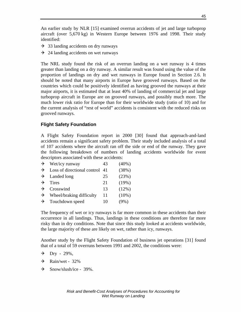
Risk and Benefit-Cost Analyses of Procedures for Accounting for
Wet Runway on Landing
45
An earlier study by NLR [15] examined overrun accidents of jet and large turboprop aircraft (over 5,670 kg) in Western Europe between 1976 and 1998. Their study identified:
33 landing accidents on dry runways 24 landing accidents on wet runways
The NRL study found the risk of an overrun landing on a wet runway is 4 times greater than landing on a dry runway. A similar result was found using the value of the proportion of landings on dry and wet runways in Europe found in Section 2.6. It should be noted that many airports in Europe have grooved runways. Based on the countries which could be positively identified as having grooved the runways at their major airports, it is estimated that at least 40% of landing of commercial jet and large turboprop aircraft in Europe are on grooved runways, and possibly much more. The much lower risk ratio for Europe than for their worldwide study (ratio of 10) and for the current analysis of “rest of world” accidents is consistent with the reduced risks on grooved runways. Flight Safety Foundation A Flight Safety Foundation report in 2000 [30] found that approach-and-land accidents remain a significant safety problem. Their study included analysis of a total of 107 accidents where the aircraft ran off the side or end of the runway. They gave the following breakdown of numbers of landing accidents worldwide for event descriptors associated with these accidents:
Wet/icy runway 43 (40%) Loss of directional control 41 (38%) Landed long 25 (23%) Tires 21 (19%) Crosswind 13 (12%) Wheel/braking difficulty 11 (10%) Touchdown speed 10 (9%)
The frequency of wet or icy runways is far more common in these accidents than their occurrence in all landings. Thus, landings in these conditions are therefore far more risky than in dry conditions. Note that since this study looked at accidents worldwide, the large majority of these are likely on wet, rather than icy, runways. Another study by the Flight Safety Foundation of business jet operations [31] found that of a total of 59 overruns between 1991 and 2002, the conditions were:
Dry - 29%,
Rain/wet - 32%
Snow/slush/ice - 39%.

Risk and Benefit-Cost Analyses of Procedures for Accounting for
Wet Runway on Landing
46
Risks of overruns are therefore much greater in wet and contaminated conditions than in dry conditions. The study notes that business aircraft often land at smaller airports that do not have grooved or PFC overlay surface runways and that 59% of the business aircraft landing overrun accidents occurred on runways lacking these wet runway friction enhancements. The risk ratios, wet:dry, is therefore approximately 6, assuming the percentage of the time the runway is dry, wet and contaminated is 83%, 15% and 2%, respectively. Australian Transport Safety Bureau A study by the Australian Transport Safety Bureau (ATSB) [32] of landing overrun accidents worldwide found similar results. Of 111 jets overrun accidents between 1970 and 1998 (excluding those with mechanical failure that led to the accident) the study found that in:
38% the aircraft landed long and/or fast on a water-affected runway;
32% touchdown was apparently normal on a water-affected runway; and
30% the aircraft landed long and/or fast on a dry runway. Preliminary data on 11 jet overrun accidents in 1999 collected by the ATSB indicated that the aircraft landed long and/or fast on a water-affected runway in 45% of cases and in poor weather conditions (runway conditions not stated) in a further 18% of cases. Kirkland and Caves Kirkland and Caves [33] undertook an analysis of 137 jet and turboprop landing overrun occurrences in the U.S., UK, Australia and Canada. Their database had an overrepresentation of accidents due to the unavailability of reports for many overrun incidents. Some of their findings relevant to the current study are summarized below.
Touchdown points in overrun accidents were typically much farther down the runway than in non-overrun landings. For example, in 33% of overrun landings, the aircraft touched down past 2,500 ft. from the threshold, but only 5% of non-overrun landings touched down this far down the runway.
Landing speed was known to have been excessive in 22% of landing overruns.
51% of landing overruns occurred on dry runways, 34% occurred on runways that were very wet or flooded, and 15% were on runways contaminated by snow, ice or slush.
Other factors that were commonly associated with overruns on landing in order of importance were: • Wet weather, • Tailwind, • Poor visibility, • Aircraft equipment or functional problem after touchdown,

Risk and Benefit-Cost Analyses of Procedures for Accounting for
Wet Runway on Landing
47
• Improper use of aircraft equipment, • Poor approach planning, and • Procedures not followed.
Average overrun distances were around 100 ft. with almost all being less than 1,000 ft.
In 80% of the accidents where the aircraft was substantially damaged or destroyed, the aircraft encountered an obstacle on the overrun, and in 95% of overruns where an obstacle was not encountered the aircraft suffered little or no damage.
Captain Ranganathan – ALAR India Project Captain Ranganathan looked at the problem of landing on wet runways [34] and produced an adverse weather operations tool kit which is used for training all airline pilots in India. Since 2004 he found a dramatic increase in the number of wet runway overruns/excursions. In the majority of cases pilot error had been identified as the cause. He argues that the relevant information is not being provided to the pilot. He notes that the reduction in braking friction is a function of the material and techniques used to construct the runway and rubber deposits can make the runway surface potentially lethal in wet conditions. He also points out that for most wet runway overrun and excursion accidents, the actual condition of the runway is not reported to pilots. He states that “the FAA has no clear definition of wet runways”, and that “the JAA rules still have some grey areas”. “The only information a pilot gets is based on the assumption that the water depth is less than 3 mm when the runway is reported wet. The air traffic controllers rarely report “contaminated” [flooded] or “slippery” conditions. In his 30 years of flying he has never heard the runway being reported as anything but “wet” in heavy rainfall conditions. The wet runway condition becomes more critical in heavy rain and in crosswinds. Even on grooved runways the water depth can be more than 15 mm during periods of very heavy rain.” From an analysis of overrun accidents and photos of aircraft stopping on very wet runways he notes that use of maximum reverse thrust can push the water in front of the main wheels effectively making the water deeper and causing hydroplaning. He suggest manufacturers consider a minor change to the reverser flow, and that for current reverse thrust designs, reverse thrust 10% to 15% less than maximum be used on wet runways. Studies by the Indian Director-General of Civil Aviation have established that more than 45% of all landing accidents take place in heavy rain. Captain Ranganathan concludes that building grooved runways, investing in modern runway friction recording equipment, and proactive runway condition reporting are essential for making landing on wet runways safe.
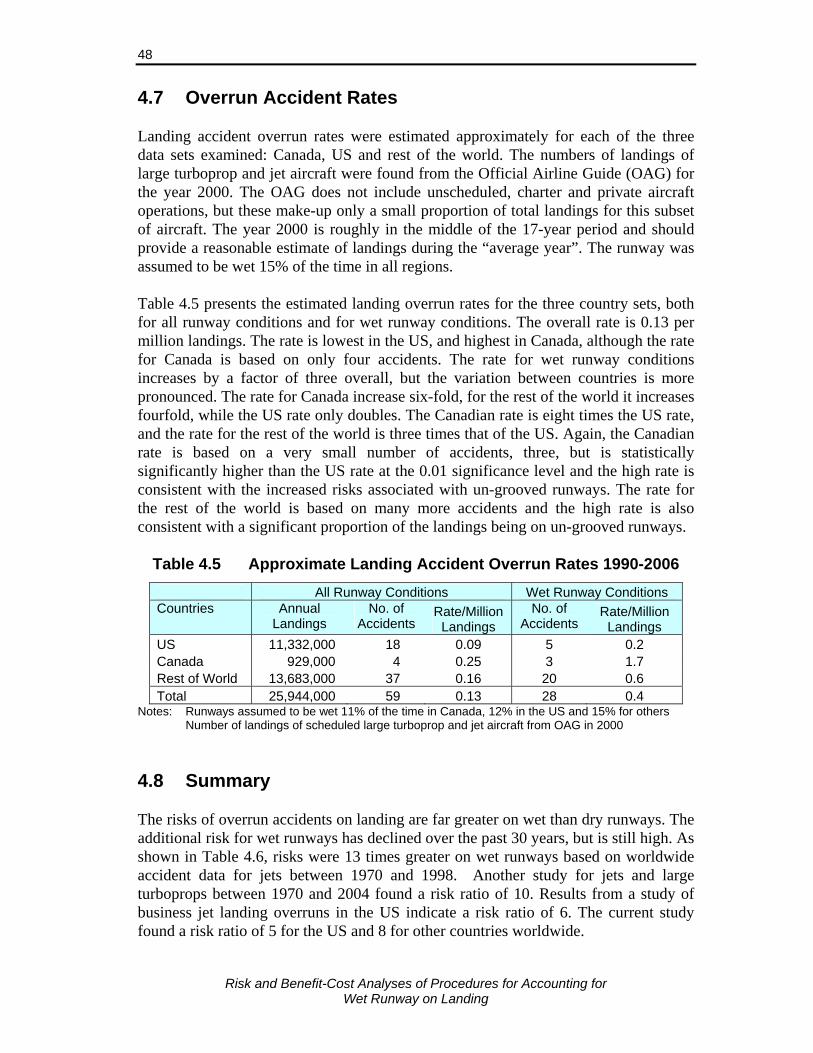
Risk and Benefit-Cost Analyses of Procedures for Accounting for
Wet Runway on Landing
48
4.7 Overrun Accident Rates Landing accident overrun rates were estimated approximately for each of the three data sets examined: Canada, US and rest of the world. The numbers of landings of large turboprop and jet aircraft were found from the Official Airline Guide (OAG) for the year 2000. The OAG does not include unscheduled, charter and private aircraft operations, but these make-up only a small proportion of total landings for this subset of aircraft. The year 2000 is roughly in the middle of the 17-year period and should provide a reasonable estimate of landings during the “average year”. The runway was assumed to be wet 15% of the time in all regions. Table 4.5 presents the estimated landing overrun rates for the three country sets, both for all runway conditions and for wet runway conditions. The overall rate is 0.13 per million landings. The rate is lowest in the US, and highest in Canada, although the rate for Canada is based on only four accidents. The rate for wet runway conditions increases by a factor of three overall, but the variation between countries is more pronounced. The rate for Canada increase six-fold, for the rest of the world it increases fourfold, while the US rate only doubles. The Canadian rate is eight times the US rate, and the rate for the rest of the world is three times that of the US. Again, the Canadian rate is based on a very small number of accidents, three, but is statistically significantly higher than the US rate at the 0.01 significance level and the high rate is consistent with the increased risks associated with un-grooved runways. The rate for the rest of the world is based on many more accidents and the high rate is also consistent with a significant proportion of the landings being on un-grooved runways.
Table 4.5 Approximate Landing Accident Overrun Rates 1990-2006
All Runway Conditions Wet Runway Conditions Countries Annual
Landings No. of
Accidents Rate/Million
Landings No. of
Accidents Rate/Million
Landings US 11,332,000 18 0.09 5 0.2 Canada 929,000 4 0.25 3 1.7 Rest of World 13,683,000 37 0.16 20 0.6 Total 25,944,000 59 0.13 28 0.4
Notes: Runways assumed to be wet 11% of the time in Canada, 12% in the US and 15% for others Number of landings of scheduled large turboprop and jet aircraft from OAG in 2000 4.8 Summary The risks of overrun accidents on landing are far greater on wet than dry runways. The additional risk for wet runways has declined over the past 30 years, but is still high. As shown in Table 4.6, risks were 13 times greater on wet runways based on worldwide accident data for jets between 1970 and 1998. Another study for jets and large turboprops between 1970 and 2004 found a risk ratio of 10. Results from a study of business jet landing overruns in the US indicate a risk ratio of 6. The current study found a risk ratio of 5 for the US and 8 for other countries worldwide.
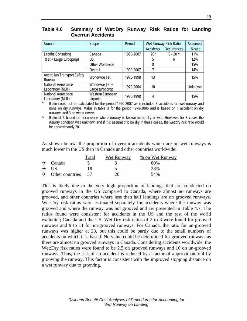
Risk and Benefit-Cost Analyses of Procedures for Accounting for
Wet Runway on Landing
49
Table 4.6 Summary of Wet:Dry Runway Risk Ratios for Landing Overrun Accidents
Source Scope Period Wet Runway Risk Ratio Assumed Accidents Occurrences % wet Jacobs Consulting Canada 1990-2007 20* 6 - 20 ^ 11% (Jet + Large turboprop) US 5 6 12% Other Worldwide 8 15% Overall 1990-2007 7 14% Australian Transport Safety Bureau Worldwide Jet 1970-1998 13 15%
National Aerospace Laboratory (NLR)
Worldwide Jet + Large turboprop 1970-2004 10 Unknown
National Aerospace Laboratory (NLR)
Western European airports 1976-1998 4 15%
* Ratio could not be calculated for the period 1990-2007 as it included 3 accidents on wet runway and none on dry runways. Value in table is for the period 1978-2006 and is based on 1 accident on dry runways and 3 on wet runways.
^ Ratio of 6 based on occurrence where runway is known to be dry or wet. However, for 8 cases the runway condition was unknown and if it is assumed to be dry in these cases, the wet:dry risk ratio would be approximately 20.
As shown below, the proportion of overrun accidents which are on wet runways is much lower in the US than in Canada and other countries worldwide:
Total Wet Runway % on Wet Runway Canada 5 3 60% US 18 5 28% Other countries 37 20 54%
This is likely due to the very high proportion of landings that are conducted on grooved runways in the US compared to Canada, where almost no runways are grooved, and other countries where less than half landings are on grooved runways. Wet:Dry risk ratios were estimated separately for accidents where the runway was grooved and where the runway was not grooved and are presented in Table 4.7. The ratios found were consistent for accidents in the US and the rest of the world excluding Canada and the US. Wet:Dry risk ratios of 2 to 3 were found for grooved runways and 9 to 11 for un-grooved runways. For Canada, the ratio for un-grooved runways was higher at 23, but this could be partly due to the small numbers of accidents on which it is based. No value could be determined for grooved runways as there are almost no grooved runways in Canada. Considering accidents worldwide, the Wet:Dry risk ratios were found to be 2.5 on grooved runways and 10 on un-grooved runways. Thus, the risk of an accident is reduced by a factor of approximately 4 by grooving the runway. This factor is consistent with the improved stopping distance on a wet runway due to grooving.
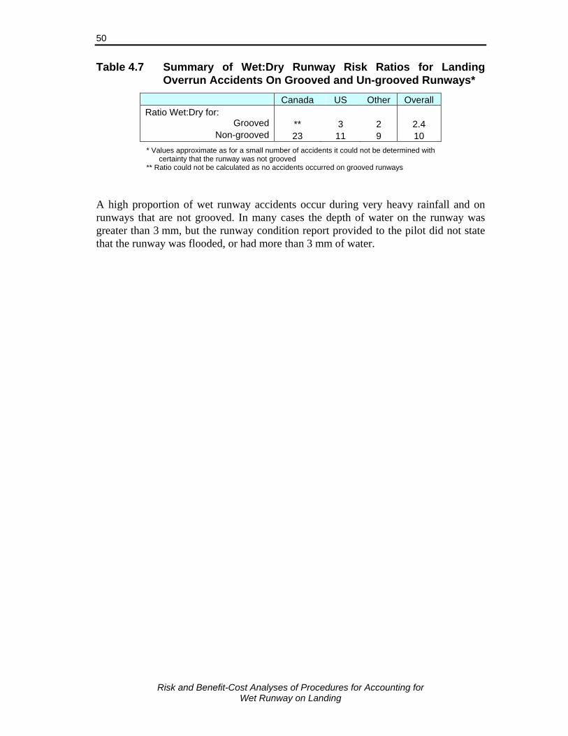
Risk and Benefit-Cost Analyses of Procedures for Accounting for
Wet Runway on Landing
50
Table 4.7 Summary of Wet:Dry Runway Risk Ratios for Landing Overrun Accidents On Grooved and Un-grooved Runways*
Canada US Other Overall Ratio Wet:Dry for:
Grooved ** 3 2 2.4 Non-grooved 23 11 9 10
* Values approximate as for a small number of accidents it could not be determined with certainty that the runway was not grooved
** Ratio could not be calculated as no accidents occurred on grooved runways A high proportion of wet runway accidents occur during very heavy rainfall and on runways that are not grooved. In many cases the depth of water on the runway was greater than 3 mm, but the runway condition report provided to the pilot did not state that the runway was flooded, or had more than 3 mm of water.
Risk and Benefit-Cost Analyses of Procedures for Accounting for
Wet Runway on Landing
51
5. RISK ANALYSIS 5.1 Description of Approach Used In considering the risks of an undesirable outcome, both the probability of the outcome and the consequences of that outcome must be considered. In the risk analysis of landing overrun accidents, the probability of an overrun occurring and the expected consequences, in terms of fatalities, injuries and aircraft damage, are considered. Risks associated with leaving the side of the runway due to crosswinds were not considered as this would greatly complicate the analysis and is outside the scope of this study. Historical rates of overruns and overrun accidents, and the proportion in which injuries and aircraft damage occurred provide some indication of the risks. However, due to the very low probability of serious accidents and the limited number of accidents, as is the case for landing accidents on wet runways, historical accident rates can be a misleading indicator of the underlying risk. These rates do not provide a good indication of the likely benefits of specific measures to reduce the risks. The use of a risk analysis model can make better use of available information and provide a better understanding of the factors affecting the risk and provide estimates of the reductions in risk of specific measures. The estimated risks under past conditions using the model should be consistent with observed accident experience. An analysis of the risks was undertaken by modelling the factors affecting landing distances and the likelihood of these effects. Many of the factors affecting landing distances are present during every landing and contribute to the uncertainty in stopping distance and the associated risks. The factors considered were the:
Touchdown distance from the runway threshold which is affected by factors such as height above the runway threshold on approach, approach speed, approach angle, head/tail and crosswinds, wind shear, etc.;
Speed at touchdown;
Delay time between touchdown and application of wheel brakes;
Error in setting and/or applying brakes, or malfunction of brakes;
Availability and correct application of reverse thrust; and
Depth of water on the runway and its effect on aircraft braking. The variation in these factors all lead to uncertainties in the actual stopping distance on a particular landing. In addition, other factors such as use of reverse thrust and characteristics of the runway (i.e., texture, grooving/PFC, rubber contamination, grade) are known prior to landing but are not used in determining the landing distance. By estimating the cumulative effect of all of these factors on the landing distance, applying the probabilities of each and summing over all possibilities, it is possible to estimate the probability distribution of the landing distance. The probability of an

Risk and Benefit-Cost Analyses of Procedures for Accounting for
Wet Runway on Landing
52
overrun can be determined by summing the distribution over predicted landing distances greater than the runway length available. The expected consequences of the overrun can then be determined by estimating the expected number of fatalities and injuries and the value of damage to the aircraft based on the additional distance required and the terrain at the end of the runway. The analysis was conducted for a number of common aircraft types landing under various specified conditions of runways lengths available, grade and altitude. Head and tail winds must be accounted for in determining landing distances under current regulations and these wind speeds were not considered specifically in the risk model and zero wind speed was assumed. However, the effect of variation in wind speeds on the variation in the air distance prior to touchdown and touchdown speed was considered. Similarly, temperature must be accounted for under current regulations and for simplicity, a temperature of 15°C was used in the analysis. Typical variation in landing weight was modelled. Where the landed field length required at a given weight was greater than the runway length available, the weight was reduced to the maximum allowed value. The risk model covered the full range of wet runway conditions from damp to conditions during very heavy rainfall. Risks were estimated considering the distribution of rainfall rates, and for specific rainfall rates. Risks during extremely heavy rainfall were not examined as these rainfall rates are extremely rare in Canada. The model was used to estimate the risks on a wet runway under current regulations and under each of the regulatory options being considered (see Section 5.2). The change in risk for a particular aircraft type and airport due to a particular regulatory option was found by comparison with the risks on a wet runway under current regulations. The overall risks can be found by estimating the aircraft type-airport risks for each airport and aircraft type, multiplying by the number of landings of that aircraft type at that airport, and summing over all airports and aircraft types. This step requires additional data on the distribution of rainfall rates, temperatures, winds and runway characteristics at each airport and aircraft characteristics for each aircraft type operating at these airports. These data are not readily available and the overall risks have not been estimated. It was necessary to make a number of simplifying assumptions that could affect the risks in the practical application of any requirement. These assumptions are as follows.
The decision on whether to land is made by the pilot just prior to landing based on the most recent pilot braking reports, runway surface condition report and weather report. Risks may be reduced if runway conditions are known accurately prior to departure and other measures could be taken to reduce the costs of compliance.
Forecasts of heavy rainfall at the destination airport prior to departure are not used to adjust take-off and landing weights of the aircraft unless required by the
Risk and Benefit-Cost Analyses of Procedures for Accounting for
Wet Runway on Landing
53
regulations to do so; i.e., only the regulated wet runway dispatch factor is used even if heavy rainfall is forecast. Use of these forecasts could reduce the risks, but at additional cost to the airlines.
Conditions at alternate airports are not considered. It is assumed the risks of landing when diverted are similar to the risks for landing on a wet runway of the same length under moderate rainfall conditions.
Effect of crosswinds on the landing distance and the reduction in risks when landing on wet runways in strong crosswinds due to the new requirements are not considered.
5.2 Requirements Evaluated
Currently the only additional requirement related to landing on wet runways is that at the time of dispatch the landed field length required must be increased by 15%. This results in a factor which must be applied to the AFM landing distance of 1.92 for turbojet aircraft and 1.64 for turboprop aircraft.25
Three possible requirements for wet runways were examined.
Option 1. Increased Dispatch Factors and No En Route Requirement The wet runway landing distance dispatch factor be set as follows:
Grooved or PFC Other Runways Runways • Jet without reverse thrust 2.00 2.45 • Jet with reverse thrust 1.92 2.10 • Turbopropeller aircraft 1.64 1.90
Option 2. Increased Dispatch Factors Plus En Route Requirement Use of the same dispatch factors as under Option 1 above and the requirement
that at the commencement of final approach, if:
a) The runway is un-grooved and the depth of water on the runway is greater than 3 mm or if rainfall at the airport is reported as heavy, the required landing distance must be recalculated assuming the runway is flooded (i.e., water depth greater than 3 mm) and the braking is “poor” using manufacturer’s guidance material, or
b) The runway is grooved or PFC and the depth of water on the runway is greater than 3 mm or if rainfall at the airport is reported as very heavy, the required landing distance must be recalculated assuming the runway is flooded using manufacturer’s guidance material.
If the calculated distance is less than the runway length available, the pilot must not attempt to land, except in emergency situations.
25 Landed field length required for wet runway determined by multiplying the AFM landing distance
by the factor 1.92 for jet aircraft and 1.64 for turboprop aircraft

Risk and Benefit-Cost Analyses of Procedures for Accounting for
Wet Runway on Landing
54
Option 3. Current Dispatch Factors with En Route Requirement Wet runway dispatch factors the same as under current regulations (1.92 for jet
and 1.64 for turboprop aircraft) and the en route requirement at the commencement of final approach the same as under Option 2 above.
In Option 2 and 3 requirements, heavy rainfall is taken to be when the one minute rainfall rate is equivalent to more than 10 mm (0.4 in.) per hour, and very heavy rainfall is when the one minute rainfall rate is equivalent to more than 50 mm (2.0 in.) per hour. Option 1 increases the dispatch factors for un-grooved runways and for jet aircraft without reverse thrust. The en route requirement requires that the runway be considered flooded during very heavy rainfall, and heavy rainfall on un-grooved runways. During periods of heavy rainfall water depths will often be greater than 3 mm and pilots should use landing procedures for contaminated runways if this is the case. However, as discussed in Section 2.4, airports do not measure transient water depths during heavy rainfall and the runway condition reported to the pilot is that it is wet. A qualitative description of the rainfall is also sometimes provided. Pilots do not always treat the runway as flooded during heavy rainfall and most wet runway accidents occur during heavy rainfall conditions. Thus, most of the risk associated with wet runways currently occurs during heavy rainfall conditions and it is important that these conditions are included when evaluating the risk reduction using alternate procedures. Treatment of the runway as flooded is only required during very heavy rainfall for grooved or PFC runways as the risks during heavy rainfall are much lower than on un-grooved runways. The change under Option 2 from the current regulations is minimal for grooved/PFC runways – the increased dispatch factor for aircraft without reverse thrust and the en route check and treatment of the runway as flooded if the rainfall is very heavy. Landed field length requirements set at the time of dispatch to account for the possibility of heavy rainfall upon arrival at the destination airport were not examined. The prediction of heavy rainfall during specific periods is not sufficiently accurate in most circumstances to make it reasonable to consider this as a requirement. Consideration of this type of requirement would also greatly complicate the analysis and lead to questionable results. In determining the landing distance on a wet runway credit for reverse thrust is given if it is available for that aircraft type.

Risk and Benefit-Cost Analyses of Procedures for Accounting for
Wet Runway on Landing
55
5.3 Aircraft Analyzed The aircraft types analyzed were the CRJ, B737-300, B737-700, B767-200ER, B747-400, A320-200, A340-300, DHC-8-100 and DHC-8-400. All aircraft have reverse thrust capability, or discing for the two turboprop aircraft (DHC-8-100 and 400). Most commercial jet aircraft without reverse thrust capability are regional jets and performance and risks of aircraft without reverse thrust were estimated using a CRJ with reverse thrust not used. Aircraft parameters values used in the analysis are given in Table 5.1. These parameters can vary between aircraft of the same type and the analysis of overall benefits and costs do not take this variation into account. Landing distances for very wet runways (water depths over 3 mm) were obtained from an earlier report by Sypher [21] and from data collected from several additional airlines.
Table 5.1 Aircraft Parameters Used in Risk Benefit-Cost Analysis
% Under Maximum Landing LFL* LD Ratios Wet/Dry^
Landing Weight Distance* Dry Manufacturer Material Aircraft Type Avg.
# Pass. Seats
Avg. Flight km
Max Landing
Weight (kg) Average Standard
Deviation (AFM)
(ft) (ft) Medium/
6 mm Poor
CRJ-100/200 50 955 21,300 8% 4.0% 2,910 4,850 1.42 B737-300 132 1,203 51,700 9% 4.5% 2,748 4,580 1.71 2.14 B737-700 137 2,415 58,600 10% 5.0% 2,700 4,500 B767-200ER 190 6,080 130,000 11% 5.5% 2,940 4,900 1.53 2.45** A320-200 140 1,605 72,000 9% 4.5% 2,880 4,800 1.73 A340-300 295 7,959 190,000 7.4% 3.7% 3,840 6,400 1.45 DHC8-100 37 329 13,924 10% 5.0% 1,563 2,605 DHC8-400 74 359 24,418 8% 4.0% 2,550 4,250
Source: Passenger, weights, LD and LFL – Aviation Week & Space Technology Aerospace Source Book and FAA.
Average flight distance – Official Airline Guide (flights departing from Canadian airports) % Under Maximum Weight – Estimated by Jacobs Consultancy Adjustment factors – [21], aircraft accident reports and several airlines (confidential). Notes: * Landing Distance and Landed Field Length (LFL) for sea level 15°C and zero wind ^ Landing Distance (LD) Ratios from Manufacturers materials given for flooded runway with
water depths of 6 mm. Some manufacturers give adjustments for “medium” and “poor” braking rather than a given condition. Adjustment factors assuming full reverse thrust used, if available.
** Value for B767-200ER not available, value for B777-200ER is given Guidance material with adjustment factors for landing on flooded runways was used where this information was available and is provided in Table 5.1. Where information was provided for different braking reports, the factors for “medium” braking were used for flooded grooved runways, and “poor” for flooded un-grooved runways as per the practices for airlines contacted. However, some manufacturer data obtained gave factors for given water depths (3 or 6 mm), but did not indicate whether the value was applicable for a grooved or un-grooved runway. Based on the magnitude of the values, the factors are likely applicable for grooved runways and these values were applied for grooved runways in the analysis. Where values are not provided for grooved runways, or for “poor” braking conditions, adjustment factors were estimated based on other aircraft of a similar type or similar characteristics and used for flooded grooved

Risk and Benefit-Cost Analyses of Procedures for Accounting for
Wet Runway on Landing
56
runways. Note that the wet/dry ratios for medium braking or 6 mm water depth are all less than 1.92, the wet runway dispatch factor for jet aircraft. The distribution of landing weights varies by airline and aircraft type and are not publically available. However, passenger and cargo load factors are published by airlines and industry groups and these, and available payload capacity data on aircraft, were used to estimate the landing weight distribution. The landing weights used in the analysis are expressed in terms of the percentage under maximum allowed weight. Average annual load factors for passengers are currently about 79%. Cargo load factors average around 70%, but vary greatly depending on the direction of travel and time of year. Larger aircraft usually have more cargo capacity and, since cargo load factors are lower, their percentage under maximum landing weight tends to be higher (i.e., lower average weights). The standard deviation of the percentage under maximum weight was set to half the mean value so that the aircraft is at maximum weight 3% of landings. Due to the uncertainty in the estimated distribution of weights, the risk analysis is conducted for both the maximum landing weights and the estimated distribution of landing weights. 5.4 Determining Consequences of an Overrun The consequences of an overrun, or the potential benefits of preventing the overrun, were estimated using the same approach as that used by Sypher [29, 35] in their benefit-cost analysis of measures to account for effects of slippery runway conditions on landing. The consequences of an accident were measured in terms of the number of fatalities, numbers of serious injuries and the cost of damage to the aircraft. Estimation of Distribution of Landing Distances The approach used to estimate the landing distance is similar to that used by Croll, Martin and Bastian [36], Croll and Bastian [23, 24], Martin [25, 26, 27] and ESDU [37]. In this approach, the landing distance is divided into three segments denoted by D1, D2 and D3:
D1 Air distance – distance travelled from 50 ft. above the runway to the point of touchdown;
D2 Delay/transition distance – distance travelled between point of touchdown and application of wheel brakes; and
D3 Stopping distance – distance travelled from application of brakes until aircraft comes to a stop.
The set of parameters considered in determining the landing distance is provided in Table 5.2. The table indicates whether each factor is currently used in determining the required landed field length and whether it is considered in the current analysis.

Risk and Benefit-Cost Analyses of Procedures for Accounting for
Wet Runway on Landing
57
Table 5.2 Outline of Factors Affecting Landing Distances and Their Treatment in the Risk Model
Known on Approach Category Factor Included in Required
Landed Field Length Values Used in Modelling
Aircraft AFM Landing distance Yes Actual Landing weight Yes Est. distribution Reverse thrust capability No Actual Airport Altitude Yes Actual Runway length available Yes Longest runway* Runway slope No Actual Runway grooved/PFC No Actual (if known) Runway macro-texture No Specific values not used^ Runway condition (when dry) No Specific values not used^ Terrain at end of the runway No Actual (if known) Environmental Runway wet or contaminated Yes (inaccurate) Est. from rainfall rate Rainfall rate No Est. distribution Tail/head wind, speed & variability Partially Specific values not used^ Cross-wind, speed & variability Partially No Temperature Yes 15C Visibility Yes (partially) No Factors Considered in Determining Distribution of Actual Landing Distances All above factors where “Yes” is indicated are considered Segment Factors Considered Variation Considered Also related to Air Distance Height at Threshold Visibility, heavy rainfall, tailwind Approach slope Windshear
Variation in touchdown point Winds, heavy rainfall
Speed Variation around TD speed Transition Distance Time to activate wheel brakes Visibility, Heavy rainfall Time to activate reverse thrust
Variation in delay in applying brakes
Speed Variation around TD speed Braking distance Depth of water on runway Variation in MuB Heavy rainfall, grooved/PFC Runway grooved/PFC or not
Variation in MuB for each runway type included
Runway macro-texture Runway rubber contamination
Variation between runways included in MuB
Incorrect wheel brake setting Incorrect reverse thrust setting Malfunction of brakes Blown tire(s)
Variation in brake settings and operation (including tires)
Initial Speed Variation around TD speed
* Other runways considered at large airports ^ Effect of variation in this factor included in variation of landing distances
Risk and Benefit-Cost Analyses of Procedures for Accounting for
Wet Runway on Landing
58
The segment distances D1 and D2 were estimated based on relationships given by Croll [23, 24, 36] and EDSU [37]. The stopping distance, D3, was estimated by first calculating the stopping distance on a dry runway based on the AFM value, then multiplying by an estimate of the ratio of the stopping distances, wet:dry, for the given runway type (grooving, slope) and conditions (water depth) and aircraft parameters (reverse thrust, weight). This provides estimates of the typical stopping distance values. Stopping distances ratios are estimated for given water depths based on results of analyses by the ESDU [37]. Water depths are estimated for given rainfall rates using relationships developed by Horne [6, 7]. These estimates may be only approximate in particular situations and errors in the estimates are allowed for in the analysis by allowing for variation in stopping distance ratios. The variation around the estimated typical values also accounts for the variation in factors such as runway texture (apart from grooving), runway rubber contamination, aircraft drag and reverse thrust level, tire wear, etc. The method used for estimating the landing distance, allowing for the variation in these factors, is provided in Appendix C. Runways at almost all airports with frequent jet and large turboprop aircraft have sufficient drainage that so water depths of more than 3 mm are usually transient events and only occur during periods of heavy rainfall. The risk analysis assumes that water depths are directly related to the rainfall rate at that time, and there is no delay in the reduction in water depths as the rain eases off. The AFM distance, required for estimating D3, is available for standard conditions (sea level, 15ºC, zero wind, maximum landing weight, zero grade – see Table 5.1) and was adjusted for the actual pressure-altitude, landing weight and grade using a similar approach to Sypher [29]. The approach and parameters are described in Appendix C. Both tail winds and downhill slopes have a much greater effect on the landing distance when the runway is very wet or flooded than when it is dry. When determining landing distance, it may be reasonable to exclude these factors for a dry runway, as is the case under current regulations, but excluding them when the runway is very wet or flooded can result in significant underestimation of the landing distance. Very heavy rainfall is very often associated with strong, gusty winds and wind shear, and can also greatly reduce the pilot’s visibility through the windshield of the aircraft. Reduced visibility can affect the touchdown point and delay application of the brakes. These factors often occur in conjunction with heavy rainfall in landing overruns on wet runways. It is therefore important in the risk analysis to allow for the dependency of these factors. In the absence of good operational data on the frequency of these dependent factors, values were estimated based on a review of historical overrun data and included in the model. Expected Numbers of Fatalities and Serious Injuries The approach used for estimating the expected numbers of fatalities and serious injuries was similar to that used by Sypher [29, 35]. Relationships were derived for estimating the expected numbers of fatalities and serious injuries and the expected
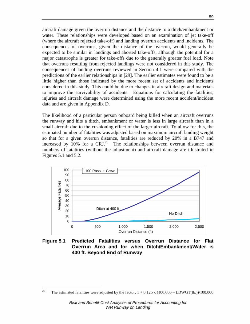
Risk and Benefit-Cost Analyses of Procedures for Accounting for
Wet Runway on Landing
59
aircraft damage given the overrun distance and the distance to a ditch/embankment or water. These relationships were developed based on an examination of jet take-off (where the aircraft rejected take-off) and landing overrun accidents and incidents. The consequences of overruns, given the distance of the overrun, would generally be expected to be similar in landings and aborted take-offs, although the potential for a major catastrophe is greater for take-offs due to the generally greater fuel load. Note that overruns resulting from rejected landings were not considered in this study. The consequences of landing overruns reviewed in Section 4.1 were compared with the predictions of the earlier relationships in [29]. The earlier estimates were found to be a little higher than those indicated by the more recent set of accidents and incidents considered in this study. This could be due to changes in aircraft design and materials to improve the survivability of accidents. Equations for calculating the fatalities, injuries and aircraft damage were determined using the more recent accident/incident data and are given in Appendix D. The likelihood of a particular person onboard being killed when an aircraft overruns the runway and hits a ditch, embankment or water is less in large aircraft than in a small aircraft due to the cushioning effect of the larger aircraft. To allow for this, the estimated number of fatalities was adjusted based on maximum aircraft landing weight so that for a given overrun distance, fatalities are reduced by 20% in a B747 and increased by 10% for a CRJ.26 The relationships between overrun distance and numbers of fatalities (without the adjustment) and aircraft damage are illustrated in Figures 5.1 and 5.2.
0102030405060708090
100
0 500 1,000 1,500 2,000 2,500Overrun Distance (ft)
Ave
rage
Fat
aliti
es
No DitchDitch at 400 ft
100 Pass. + Crew
Figure 5.1 Predicted Fatalities versus Overrun Distance for Flat
Overrun Area and for when Ditch/Embankment/Water is 400 ft. Beyond End of Runway
26 The estimated fatalities were adjusted by the factor: 1 + 0.125 x (100,000 – LDWGT(lb.))/100,000

Risk and Benefit-Cost Analyses of Procedures for Accounting for
Wet Runway on Landing
60
$0
$2
$4
$6
$8
$10
$12
0 100 200 300 400 500 600 700 800 900 1,000Overrun Distance (ft)
Cos
t of D
amag
e ($
mill
ion)
No Ditch
Ditch at 400 ft
Aircraft Value $10 million
Figure 5.2 Predicted Aircraft Damage versus Overrun Distance for Flat
Overrun Area and for when Ditch/Embankment/Water is 400 ft. Beyond End of Runway
The expected number of serious injuries was estimated to be three times the number of fatalities based on an examination of the accident reports. As in the earlier Sypher studies [29, 35], the overrun distance is estimated to be 50% of the additional runway required. 5.5 Verification of Risk Model The risk model was developed using various aircraft, braking and operating characteristics largely independent of the historical overrun accident and incident experience for wet runways. The probabilities of landing very long or at very high speeds, above those that typically occur in normal operations, were adjusted so that the overrun rate on a dry runway matched, at least approximately, the historical experience. To be useful for understanding the risks and determining the reductions in risk due to alternate regulatory requirements, the model should give estimates of the risk which match, at least approximately, with past experience. Probabilities of overruns were estimated under various conditions and compared with historical overrun experience. Both the overall overrun rate and the ratio of rates for landings with and without reverse thrust, on grooved and un-grooved runways, and in wet and dry conditions, were considered. Canadian overrun experience was used for comparisons with un-grooved runways, while for grooved runways, experience in the US was used. Note that the variation in operational characteristics such as touchdown point, excess speed, etc. do not vary with jurisdiction in the model and this may result in some differences between the model and overrun rates in particular countries. Also, the rainfall rate distribution used is applicable to Canada and will differ to some extent in the US.
Risk and Benefit-Cost Analyses of Procedures for Accounting for
Wet Runway on Landing
61
The probabilities of an overrun were estimated for a range of aircraft types and runway lengths allowing for typical variation in aircraft weights and rainfall rates in Canada. The risks depend greatly on the runways the aircraft operate on, and those vary by category of aircraft. Four categories were modelled and the representative aircraft modelled for each category were as follows:
Regional jet CRJ-200
Narrow-body jet A320-200 and B737-700
Wide-body jet B767-200ER, A340-300
Large turboprop DCH-8-100 Aircraft without reverse thrust, primarily regional jets, were included as a separate category due to their higher overrun risks. Wet Runway Overrun Rates The overrun rates for the different aircraft types and runway lengths, applicable for un-grooved wet runways, were estimated using the model are given in Table 5.3. Values are given for three runway lengths for each aircraft and these are given as the additional runway length typically available in excess of that provided by the current regulations when the aircraft is at maximum weight. Values are given for three cases chosen to represent short, medium and long runways for the particular aircraft type. On short runways where there is little or no additional runway length available, the overrun rates are high, between 40 and 240 per million landings for aircraft with reverse thrust, depending on the aircraft type, and 360 per million for aircraft without reverse thrust. The rates drop sharply as the runway available increases, but this varies between aircraft. Rates for the regional and narrow-body jets fall more quickly than for the wide-body. The overrun rate for the large turboprop aircraft examined is greater than for the jet aircraft: 349 per million on short runways for that type, and 0.24 per million for medium length runways (with 1,000 ft. of additional runway). The rates for short, medium and long runway distances for each aircraft type were assumed to be representative of landings in those three distance groups. These rates were weighted by the proportion of landings of those aircraft in those distance groups to estimate the overall rate for that aircraft. The weights were determined from the number of departures by aircraft in each category from each airport in Canada. The percentage weights used in the analysis are provided in Table 5.3 (right column).
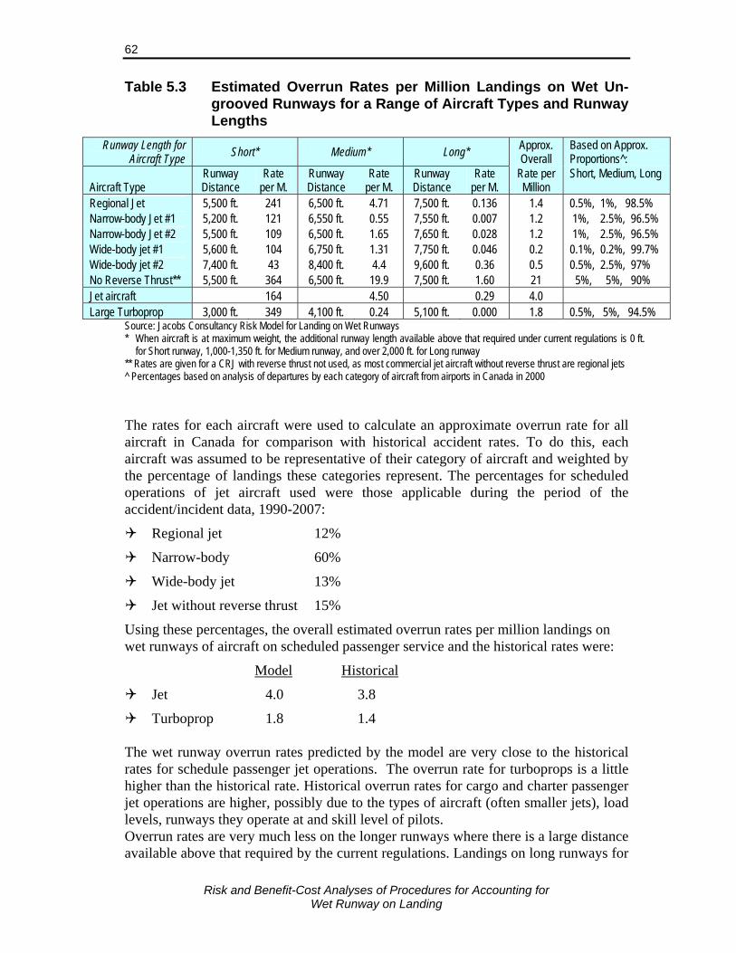
Risk and Benefit-Cost Analyses of Procedures for Accounting for
Wet Runway on Landing
62
Table 5.3 Estimated Overrun Rates per Million Landings on Wet Un-grooved Runways for a Range of Aircraft Types and Runway Lengths
Runway Length for Aircraft Type Short* Medium* Long* Approx.
Overall Based on Approx. Proportions^:
Aircraft Type Runway Distance
Rate per M.
Runway Distance
Rate per M.
Runway Distance
Rate per M.
Rate per Million
Short, Medium, Long
Regional Jet 5,500 ft. 241 6,500 ft. 4.71 7,500 ft. 0.136 1.4 0.5%, 1%, 98.5% Narrow-body Jet #1 5,200 ft. 121 6,550 ft. 0.55 7,550 ft. 0.007 1.2 1%, 2.5%, 96.5% Narrow-body Jet #2 5,500 ft. 109 6,500 ft. 1.65 7,650 ft. 0.028 1.2 1%, 2.5%, 96.5% Wide-body jet #1 5,600 ft. 104 6,750 ft. 1.31 7,750 ft. 0.046 0.2 0.1%, 0.2%, 99.7% Wide-body jet #2 7,400 ft. 43 8,400 ft. 4.4 9,600 ft. 0.36 0.5 0.5%, 2.5%, 97% No Reverse Thrust** 5,500 ft. 364 6,500 ft. 19.9 7,500 ft. 1.60 21 5%, 5%, 90% Jet aircraft 164 4.50 0.29 4.0 Large Turboprop 3,000 ft. 349 4,100 ft. 0.24 5,100 ft. 0.000 1.8 0.5%, 5%, 94.5%
Source: Jacobs Consultancy Risk Model for Landing on Wet Runways * When aircraft is at maximum weight, the additional runway length available above that required under current regulations is 0 ft.
for Short runway, 1,000-1,350 ft. for Medium runway, and over 2,000 ft. for Long runway ** Rates are given for a CRJ with reverse thrust not used, as most commercial jet aircraft without reverse thrust are regional jets ^ Percentages based on analysis of departures by each category of aircraft from airports in Canada in 2000 The rates for each aircraft were used to calculate an approximate overrun rate for all aircraft in Canada for comparison with historical accident rates. To do this, each aircraft was assumed to be representative of their category of aircraft and weighted by the percentage of landings these categories represent. The percentages for scheduled operations of jet aircraft used were those applicable during the period of the accident/incident data, 1990-2007:
Regional jet 12%
Narrow-body 60%
Wide-body jet 13%
Jet without reverse thrust 15%
Using these percentages, the overall estimated overrun rates per million landings on wet runways of aircraft on scheduled passenger service and the historical rates were:
Model Historical
Jet 4.0 3.8
Turboprop 1.8 1.4 The wet runway overrun rates predicted by the model are very close to the historical rates for schedule passenger jet operations. The overrun rate for turboprops is a little higher than the historical rate. Historical overrun rates for cargo and charter passenger jet operations are higher, possibly due to the types of aircraft (often smaller jets), load levels, runways they operate at and skill level of pilots. Overrun rates are very much less on the longer runways where there is a large distance available above that required by the current regulations. Landings on long runways for

Risk and Benefit-Cost Analyses of Procedures for Accounting for
Wet Runway on Landing
63
the particular aircraft type (i.e., having over 2,000 ft. of additional runway available when aircraft is at maximum weight), account for over 95% of landings, but contribute to only 5-10% of overruns based on the results of the risk model. Historically, almost 70% of overruns in Canada have been on runways which exceed the landed field length required for that aircraft when at maximum weight by 0 to 3,000 ft.27 Thus, the model is consistent with historical data in attributing most of the risk to aircraft landing on shorter runways for that aircraft type, but it underestimates the risk a little for landings on long runways for that aircraft type. Results of the risk model for different rainfall rates were examined to ensure they are consistent with historical accident experience during heavy rainfall. Using overrun rates found for the CRJ with typical variation in rainfall rates in Canada and typical landing weights on a short runway, the proportion of predicted accidents during heavy rainfall were calculated and are compared with historical values in Table 5.4. The percentages of overruns during heavy rainfall on un-grooved runways predicted by the model is 32%, which is between the values of 20% and 60% observed in Canada and other countries (excluding the US) between 1990 and 2007. The model predicts a very low value of 1% of overruns during heavy rainfall for grooved runways. This is consistent with the low values found in “other countries”, but is lower than the 9% found for the US. This percentage is based on two overruns during heavy rainfall, one a large turboprop on scheduled service and the other, a business jet. Considering only scheduled passenger services, differences from the model value are not statistically significant.28 The higher rate could also have been due to a higher proportion of the time rainfall is categorized as heavy, compared to Canada. Alternatively, the higher rate than predicted during heavy rainfall in both the US on grooved runways and other countries on un-grooved runways may be due to the model underestimating the risks in these situations. Table 5.4 Percentage of Wet Runway Overruns* that Occur During
Heavy Rainfall
Source Un-grooved Runways Grooved Runways Risk Model 32% 1% Historical
Canada 20% US 9%
Other Countries 60% 0% * Overrun accident for “other countries”
27 Based on overruns given in Table 4.2 28 The expected number of overruns in the US during heavy rainfall over period 1990-2006 based on
the value of 1.1% predicted by the model is 0.25 overruns. The probability of at least 1 overrun is therefore 0.23 (assuming a Poisson distribution), well above the usual level of 0.05 used for identifying statistically significant results. The probability of at least 2 overruns is 0.04, which is statistically significant at the 0.05 level, but not by much. The chance of the two overruns given the model value is correct is 4 in 100.
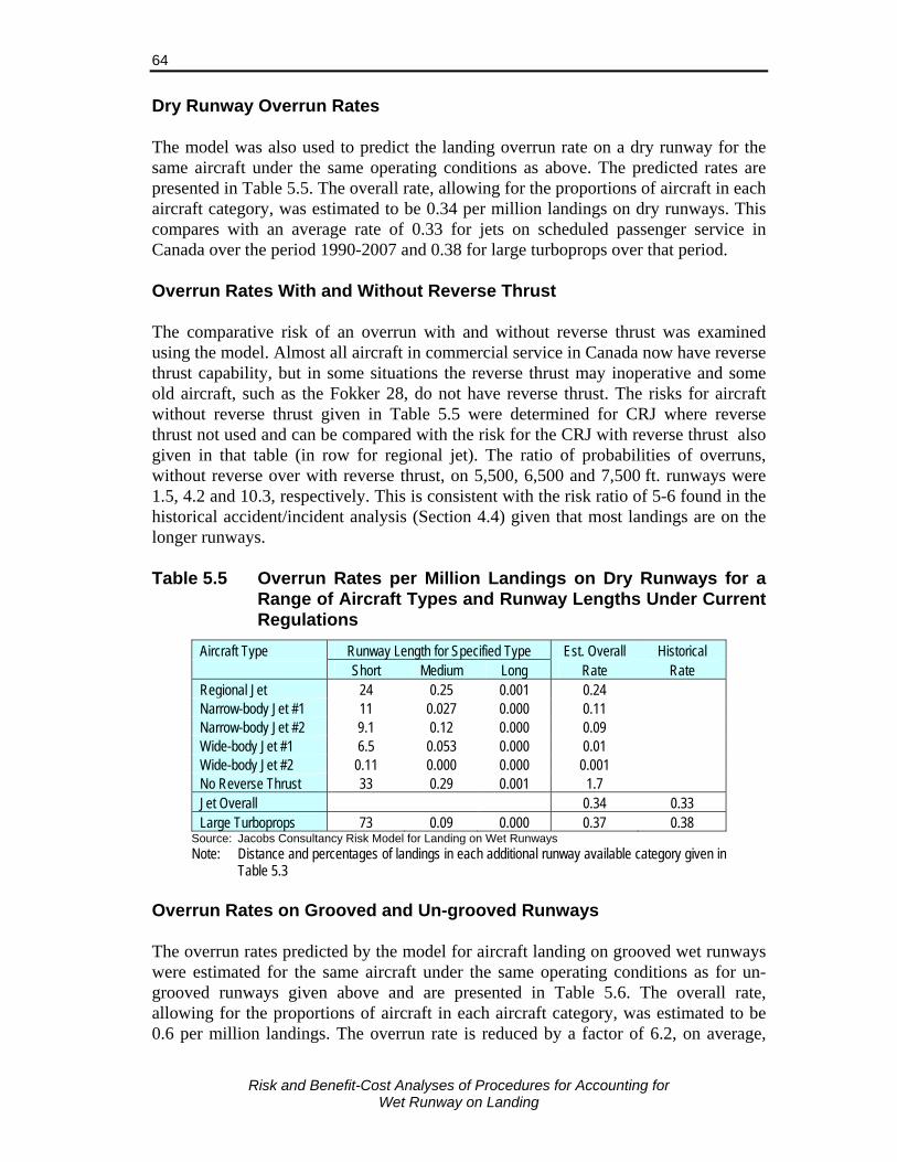
Risk and Benefit-Cost Analyses of Procedures for Accounting for
Wet Runway on Landing
64
Dry Runway Overrun Rates The model was also used to predict the landing overrun rate on a dry runway for the same aircraft under the same operating conditions as above. The predicted rates are presented in Table 5.5. The overall rate, allowing for the proportions of aircraft in each aircraft category, was estimated to be 0.34 per million landings on dry runways. This compares with an average rate of 0.33 for jets on scheduled passenger service in Canada over the period 1990-2007 and 0.38 for large turboprops over that period. Overrun Rates With and Without Reverse Thrust The comparative risk of an overrun with and without reverse thrust was examined using the model. Almost all aircraft in commercial service in Canada now have reverse thrust capability, but in some situations the reverse thrust may inoperative and some old aircraft, such as the Fokker 28, do not have reverse thrust. The risks for aircraft without reverse thrust given in Table 5.5 were determined for CRJ where reverse thrust not used and can be compared with the risk for the CRJ with reverse thrust also given in that table (in row for regional jet). The ratio of probabilities of overruns, without reverse over with reverse thrust, on 5,500, 6,500 and 7,500 ft. runways were 1.5, 4.2 and 10.3, respectively. This is consistent with the risk ratio of 5-6 found in the historical accident/incident analysis (Section 4.4) given that most landings are on the longer runways. Table 5.5 Overrun Rates per Million Landings on Dry Runways for a
Range of Aircraft Types and Runway Lengths Under Current Regulations
Aircraft Type Runway Length for Specified Type Est. Overall Historical Short Medium Long Rate Rate Regional Jet 24 0.25 0.001 0.24 Narrow-body Jet #1 11 0.027 0.000 0.11 Narrow-body Jet #2 9.1 0.12 0.000 0.09 Wide-body Jet #1 6.5 0.053 0.000 0.01 Wide-body Jet #2 0.11 0.000 0.000 0.001 No Reverse Thrust 33 0.29 0.001 1.7 Jet Overall 0.34 0.33 Large Turboprops 73 0.09 0.000 0.37 0.38
Source: Jacobs Consultancy Risk Model for Landing on Wet Runways Note: Distance and percentages of landings in each additional runway available category given in
Table 5.3 Overrun Rates on Grooved and Un-grooved Runways The overrun rates predicted by the model for aircraft landing on grooved wet runways were estimated for the same aircraft under the same operating conditions as for un-grooved runways given above and are presented in Table 5.6. The overall rate, allowing for the proportions of aircraft in each aircraft category, was estimated to be 0.6 per million landings. The overrun rate is reduced by a factor of 6.2, on average,
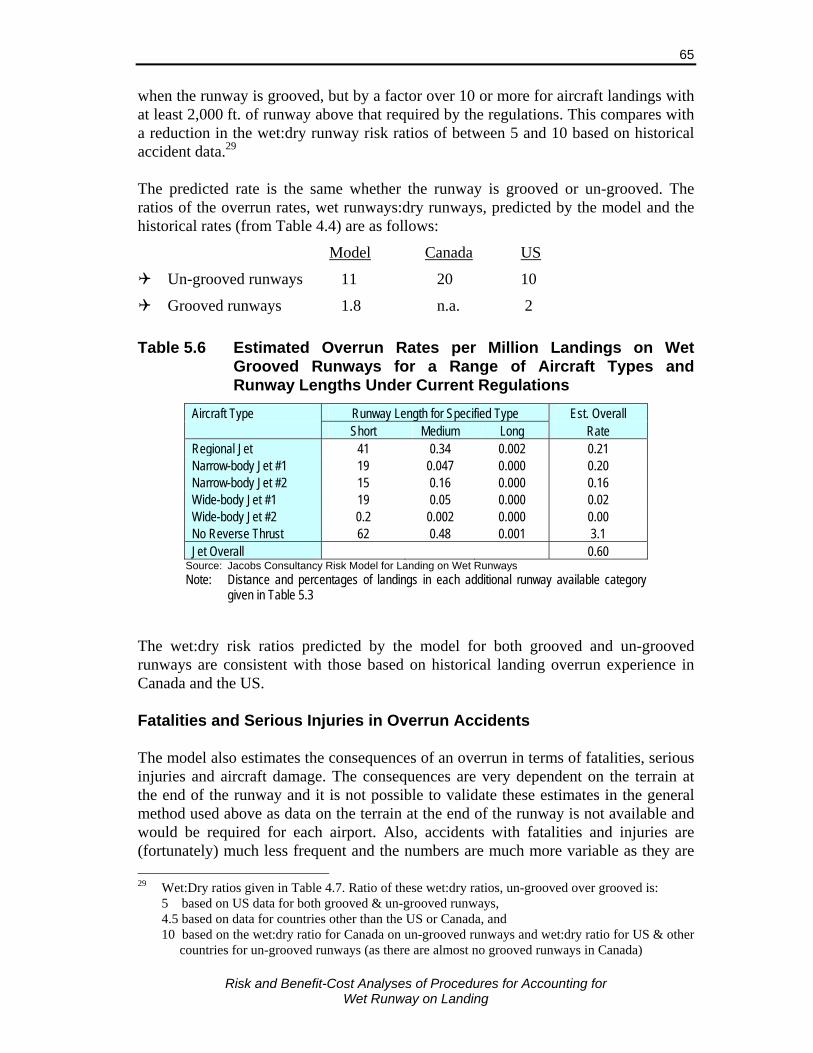
Risk and Benefit-Cost Analyses of Procedures for Accounting for
Wet Runway on Landing
65
when the runway is grooved, but by a factor over 10 or more for aircraft landings with at least 2,000 ft. of runway above that required by the regulations. This compares with a reduction in the wet:dry runway risk ratios of between 5 and 10 based on historical accident data.29 The predicted rate is the same whether the runway is grooved or un-grooved. The ratios of the overrun rates, wet runways:dry runways, predicted by the model and the historical rates (from Table 4.4) are as follows:
Model Canada US
Un-grooved runways 11 20 10
Grooved runways 1.8 n.a. 2 Table 5.6 Estimated Overrun Rates per Million Landings on Wet
Grooved Runways for a Range of Aircraft Types and Runway Lengths Under Current Regulations
Aircraft Type Runway Length for Specified Type Est. Overall Short Medium Long Rate Regional Jet 41 0.34 0.002 0.21 Narrow-body Jet #1 19 0.047 0.000 0.20 Narrow-body Jet #2 15 0.16 0.000 0.16 Wide-body Jet #1 19 0.05 0.000 0.02 Wide-body Jet #2 0.2 0.002 0.000 0.00 No Reverse Thrust 62 0.48 0.001 3.1 Jet Overall 0.60
Source: Jacobs Consultancy Risk Model for Landing on Wet Runways Note: Distance and percentages of landings in each additional runway available category
given in Table 5.3 The wet:dry risk ratios predicted by the model for both grooved and un-grooved runways are consistent with those based on historical landing overrun experience in Canada and the US. Fatalities and Serious Injuries in Overrun Accidents The model also estimates the consequences of an overrun in terms of fatalities, serious injuries and aircraft damage. The consequences are very dependent on the terrain at the end of the runway and it is not possible to validate these estimates in the general method used above as data on the terrain at the end of the runway is not available and would be required for each airport. Also, accidents with fatalities and injuries are (fortunately) much less frequent and the numbers are much more variable as they are 29 Wet:Dry ratios given in Table 4.7. Ratio of these wet:dry ratios, un-grooved over grooved is: 5 based on US data for both grooved & un-grooved runways, 4.5 based on data for countries other than the US or Canada, and 10 based on the wet:dry ratio for Canada on un-grooved runways and wet:dry ratio for US & other
countries for un-grooved runways (as there are almost no grooved runways in Canada)

Risk and Benefit-Cost Analyses of Procedures for Accounting for
Wet Runway on Landing
66
based on very few accidents. The historical experience over the 17-year period therefore may not give a good indication of the underlying fatality and injury risk. Comparisons of estimated and historical rates therefore only provide an indication of whether the estimated fatalities and serious injuries are of the correct order of magnitude. Using the same jet aircraft and distributions of landings, the numbers of fatalities and serious injuries were determined using the risk model for three cases: assuming the distances from the end of the runways to an obstacle/ditch are 1,000 ft., 500 ft. and 50 ft. For these cases, the model predicted the number fatalities and injuries in jet aircraft wet runway overrun accidents in Canada between 1990 and 2007 would be:
Ditch/obstacle 1,000 ft: 0.1 fatalities and 0.3 serious injuries.
Ditch/obstacle 500 ft: 0.5 fatalities and 2 serious injuries.
Ditch/obstacle 50 ft: 15 fatalities and 46 serious injuries.
During that period there were no fatalities and 12 serious injuries, although in one accident (A340 at Toronto) there could easily have been multiple fatalities. Thus, while this comparison does not validate the model, it does show that the model gives reasonable estimates of the consequences of landing overruns. Summary The comparisons with historical overrun data indicates that the risk model provides a reasonably accurate estimate of the overrun risks on landing under current regulations and should therefore provide a good basis for analysing risks and predicting the reduction in risk due to changes in the requirements for operating on wet runways. 5.6 Current Risks The current risks estimated using the risk model are illustrated through the use of an example using a Canadair Regional Jet (CRJ) aircraft under various conditions. The risks are similar for other aircraft types after allowing for the different landing distances and lengths of runways these aircraft typically operate on. The CRJ has reverse thrust and it is assumed that reverse thrust is used when the runway condition is wet. The landed field lengths at maximum landing weight and standard conditions for the CRJ modelled under current regulations are as follows:
Dry runway 4,850 ft.
Wet runway 5,578 ft. The landing distance for landing on a flooded runway with 6 mm of water, based on Manufacturer’s guidance material, is 4,132 ft. (based on ratio of 1.42 from reference [21]). It is not known whether this distance is applicable for grooved or un-grooved runways, although the values would be consistent with that expected for a grooved runway. This is assumed to be the case.
Risk and Benefit-Cost Analyses of Procedures for Accounting for
Wet Runway on Landing
67
The current risks are examined firstly with respect to individual landings with the aircraft weight restricted by the runway length available and for specific rainfall conditions. The risks under typical rainfall conditions and aircraft weights for different runway lengths are then considered. Risks with Weight Restricted by Runway Available and Specific Rainfall Rates The probability distributions of the actual landing distances of a CRJ aircraft at maximum landing weight landing on a 5,578 ft. wet un-grooved runway in light, moderate, heavy and very heavy rain estimated using the risk model are shown in Figure 5.3. The corresponding values are given in Table 5.7. In this example the maximum landing weight and the runway length required for that weight have been used, thus only the current regulated margin of safety for a wet runway is available. With no or only light rainfall on an un-grooved runway, most landing distances are between 3,500 and 5,000 ft., and the chance of an overrun is very low, 4.2x10⁻⁴ (i.e., 4.2 in 10,000 landings). In moderate rainfall, landing distances increase a little (the distribution moves to the right in the figure), but the chance of an overrun is still low, 8.2 x10⁻⁴. In heavy and very heavy rainfall30 the landing distances increase greatly and the distribution becomes more spread out. In heavy rainfall on an un-grooved runway, 9.6% (9.6x10⁻²) of landings, with the aircraft weight restricted, would overrun the 5,578 ft. runway and in very heavy rainfall this increases to 84% of landings. Table 5.7 also includes the distribution of landing distances for the CRJ under the same conditions of restricted landing weight, except for the runway being grooved. As would be expected from the discussion in Section 3, the probabilities of shorter landing distances for a specific rainfall rate are much higher for grooved runways. Values are not given for light rainfall conditions as distances are even less than for moderate rainfall. In heavy rainfall, almost 9 in 100 landings would overrun the 5,578 ft. runway if it were un-grooved, but only 1 in 10,000 would overrun if the runway was grooved. In very heavy rainfall, 84% would overrun on an un-grooved runway, and only 0.57% on a grooved runway. The probabilities of longer overruns, with likely catastrophic consequences, are also much lower on a grooved runway. For example, for 1 million landings in heavy rainfall, 310 would require 7,000 ft. runway (i.e., overrun by 1,422 ft.) on an un-grooved runway, and only 0.2 on a grooved runway. The much lower risks on grooved runways are due to both the better drainage of water, and thus lower water depths, and the better braking and reduced chance of hydroplaning on grooved runways.
30 The risk model includes a “lower”, “medium” and “upper” level for each of the heavy and very
heavy rainfall categories. When determining risks for the heavy and very heavy categories, the “medium” level of the category was used. Thus, a rate of 30 mm/h was used for heavy rainfall, and 120 mm/h was used for very heavy rainfall.
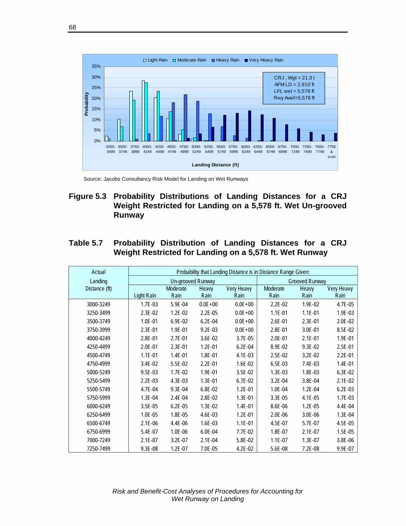
Risk and Benefit-Cost Analyses of Procedures for Accounting for
Wet Runway on Landing
68
0%
5%
10%
15%
20%
25%
30%
35%
3250-3499
3500-3749
3750-3999
4000-4249
4250-4499
4500-4749
4750-4999
5000-5249
5250-5499
5500-5749
5750-5999
6000-6249
6250-6499
6500-6749
6750-6999
7000-7249
7250-7499
7500-7749
7750&
over
Landing Distance (ft)
Prob
abili
ty
Light Rain Moderate Rain Heavy Rain Very Heavy Rain
CRJ , Wgt = 21.3 tAFM LD = 2,910 ftLFL wet = 5,578 ftRwy Avail=5,578 ft
Source: Jacobs Consultancy Risk Model for Landing on Wet Runways
Figure 5.3 Probability Distributions of Landing Distances for a CRJ
Weight Restricted for Landing on a 5,578 ft. Wet Un-grooved Runway
Table 5.7 Probability Distribution of Landing Distances for a CRJ
Weight Restricted for Landing on a 5,578 ft. Wet Runway
Actual Probability that Landing Distance is in Distance Range Given: Landing Un-grooved Runway Grooved Runway
Distance (ft) Light Rain
Moderate Rain
Heavy Rain
Very Heavy Rain
Moderate Rain
Heavy Rain
Very Heavy Rain
3000-3249 1.7E-03 5.9E-04 0.0E+00 0.0E+00 2.2E-02 1.9E-02 4.7E-05 3250-3499 2.3E-02 1.2E-02 2.2E-05 0.0E+00 1.1E-01 1.1E-01 1.9E-03 3500-3749 1.0E-01 6.9E-02 6.2E-04 0.0E+00 2.6E-01 2.3E-01 2.0E-02 3750-3999 2.3E-01 1.9E-01 9.2E-03 0.0E+00 2.8E-01 3.0E-01 8.5E-02 4000-4249 2.8E-01 2.7E-01 3.6E-02 3.7E-05 2.0E-01 2.1E-01 1.9E-01 4250-4499 2.0E-01 2.3E-01 1.2E-01 6.2E-04 8.9E-02 9.3E-02 2.5E-01 4500-4749 1.1E-01 1.4E-01 1.8E-01 4.1E-03 2.5E-02 3.2E-02 2.2E-01 4750-4999 3.4E-02 5.5E-02 2.2E-01 1.6E-02 6.5E-03 7.4E-03 1.4E-01 5000-5249 9.5E-03 1.7E-02 1.9E-01 3.5E-02 1.3E-03 1.8E-03 6.3E-02 5250-5499 2.2E-03 4.3E-03 1.3E-01 6.7E-02 3.2E-04 3.8E-04 2.1E-02 5500-5749 4.7E-04 9.3E-04 6.8E-02 1.2E-01 1.0E-04 1.2E-04 6.2E-03 5750-5999 1.3E-04 2.4E-04 2.8E-02 1.3E-01 3.3E-05 4.1E-05 1.7E-03 6000-6249 3.5E-05 6.2E-05 1.3E-02 1.4E-01 8.6E-06 1.2E-05 4.4E-04 6250-6499 1.0E-05 1.8E-05 4.6E-03 1.2E-01 2.0E-06 3.0E-06 1.3E-04 6500-6749 2.1E-06 4.4E-06 1.6E-03 1.1E-01 4.5E-07 5.7E-07 4.5E-05 6750-6999 5.4E-07 1.0E-06 6.0E-04 7.7E-02 1.8E-07 2.1E-07 1.5E-05 7000-7249 2.1E-07 3.2E-07 2.1E-04 5.8E-02 1.1E-07 1.3E-07 3.8E-06 7250-7499 9.3E-08 1.2E-07 7.0E-05 4.2E-02 5.6E-08 7.2E-08 9.9E-07
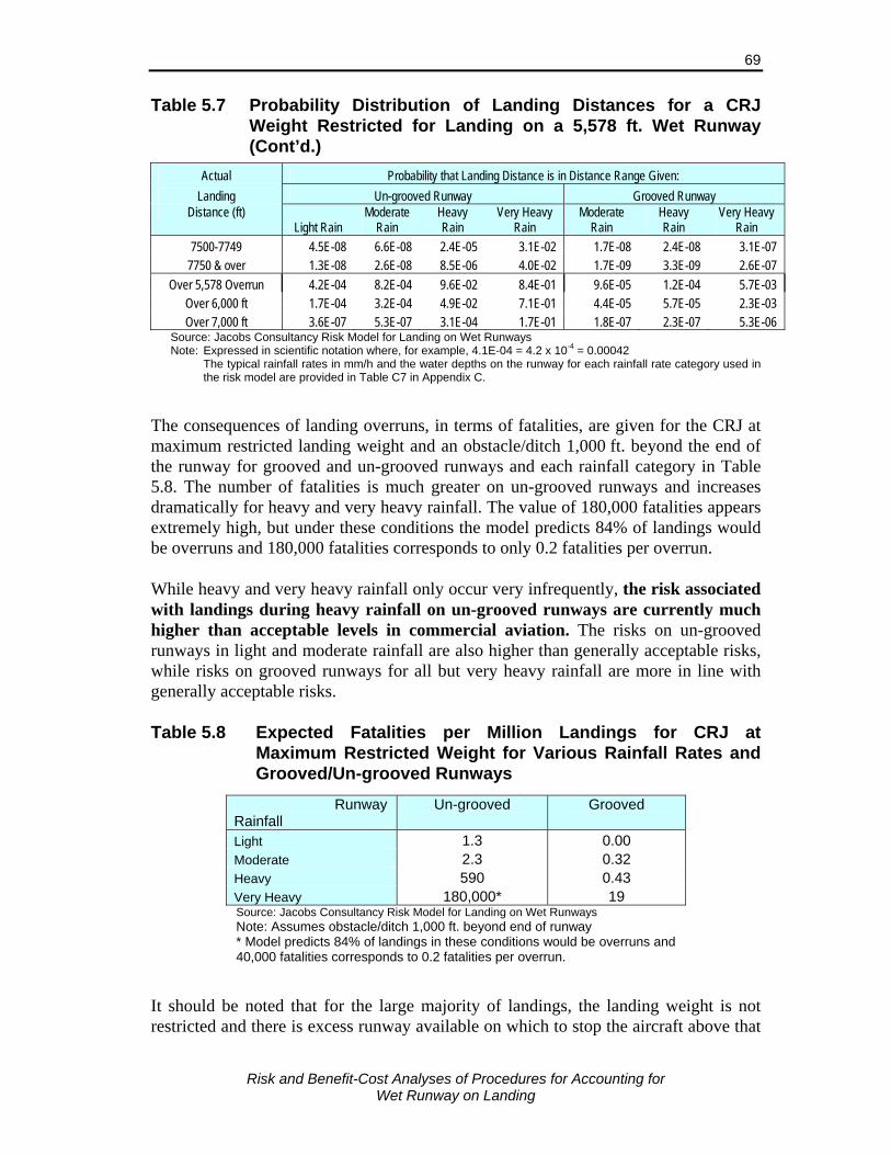
Risk and Benefit-Cost Analyses of Procedures for Accounting for
Wet Runway on Landing
69
Table 5.7 Probability Distribution of Landing Distances for a CRJ Weight Restricted for Landing on a 5,578 ft. Wet Runway (Cont’d.)
Actual Probability that Landing Distance is in Distance Range Given: Landing Un-grooved Runway Grooved Runway
Distance (ft) Light Rain
Moderate Rain
Heavy Rain
Very Heavy Rain
Moderate Rain
Heavy Rain
Very Heavy Rain
7500-7749 4.5E-08 6.6E-08 2.4E-05 3.1E-02 1.7E-08 2.4E-08 3.1E-07 7750 & over 1.3E-08 2.6E-08 8.5E-06 4.0E-02 1.7E-09 3.3E-09 2.6E-07
Over 5,578 Overrun 4.2E-04 8.2E-04 9.6E-02 8.4E-01 9.6E-05 1.2E-04 5.7E-03 Over 6,000 ft 1.7E-04 3.2E-04 4.9E-02 7.1E-01 4.4E-05 5.7E-05 2.3E-03 Over 7,000 ft 3.6E-07 5.3E-07 3.1E-04 1.7E-01 1.8E-07 2.3E-07 5.3E-06
Source: Jacobs Consultancy Risk Model for Landing on Wet Runways Note: Expressed in scientific notation where, for example, 4.1E-04 = 4.2 x 10-4 = 0.00042 The typical rainfall rates in mm/h and the water depths on the runway for each rainfall rate category used in
the risk model are provided in Table C7 in Appendix C. The consequences of landing overruns, in terms of fatalities, are given for the CRJ at maximum restricted landing weight and an obstacle/ditch 1,000 ft. beyond the end of the runway for grooved and un-grooved runways and each rainfall category in Table 5.8. The number of fatalities is much greater on un-grooved runways and increases dramatically for heavy and very heavy rainfall. The value of 180,000 fatalities appears extremely high, but under these conditions the model predicts 84% of landings would be overruns and 180,000 fatalities corresponds to only 0.2 fatalities per overrun. While heavy and very heavy rainfall only occur very infrequently, the risk associated with landings during heavy rainfall on un-grooved runways are currently much higher than acceptable levels in commercial aviation. The risks on un-grooved runways in light and moderate rainfall are also higher than generally acceptable risks, while risks on grooved runways for all but very heavy rainfall are more in line with generally acceptable risks. Table 5.8 Expected Fatalities per Million Landings for CRJ at
Maximum Restricted Weight for Various Rainfall Rates and Grooved/Un-grooved Runways
Runway Rainfall
Un-grooved
Grooved
Light 1.3 0.00 Moderate 2.3 0.32 Heavy 590 0.43 Very Heavy 180,000* 19 Source: Jacobs Consultancy Risk Model for Landing on Wet Runways Note: Assumes obstacle/ditch 1,000 ft. beyond end of runway * Model predicts 84% of landings in these conditions would be overruns and 40,000 fatalities corresponds to 0.2 fatalities per overrun.
It should be noted that for the large majority of landings, the landing weight is not restricted and there is excess runway available on which to stop the aircraft above that

Risk and Benefit-Cost Analyses of Procedures for Accounting for
Wet Runway on Landing
70
provided by the regulations. The frequencies of overruns and the additional distance required allowing for typical weights and rainfall rates are now considered. Risks Over Typical Range of Rainfall Conditions The estimated probability distribution of the additional runway distances required for the CRJ, given that the runway is un-grooved and wet is given in Table 5.9 for available runways lengths of 5,500, 6,500 and 7,500 ft. Values are given for the aircraft at maximum landing weight and for typical distributions of aircraft weights. The typical variation in rainfall rates in Canada are used in calculating these risks (see Section 2.6). At maximum landing weight the probabilities of overruns are still relatively high, over 1 in 100,000, when the runway is 6,500 ft. or less, but low for landings on longer runways. Allowing for typical variation in weights, CRJs operating at airports with 5,500 ft. or shorter un-grooved runways have a relatively high probability of overruns when the runway is wet, at least 2.4 x 10⁻⁴. On longer runways the risk decreases greatly. Table 5.9 Probabilities of Overrun by Additional Runway Distance
Required for a CRJ Given Landing on Wet Un-grooved Runway Under Current Regulations
Overrun Max. Weight for Runway Actual Weight*, for Runway Distance (ft.) 5,500 ft. 6,500 ft. 7,500 ft. 5,500 ft. 6,500 ft. 7,500 ft.
0-249 4.1E-04 1.2E-05 4.2E-07 1.6E-04 2.8E-06 9.6E-08 250-499 1.2E-04 4.4E-06 2.4E-07 5.3E-05 1.1E-06 2.7E-08 500-749 4.6E-05 1.8E-06 1.2E-07 1.7E-05 4.7E-07 1.3E-08 750-999 1.5E-05 8.2E-07 0.0E+00 5.4E-06 2.2E-07 0.0E+00
1000-1249 5.3E-06 4.2E-07 0.0E+00 1.9E-06 9.6E-08 0.0E+00 1250-1499 2.1E-06 2.4E-07 0.0E+00 8.3E-07 4.0E-08 0.0E+00 1500-1749 1.0E-06 1.2E-07 0.0E+00 3.9E-07 2.0E-08 0.0E+00 1750-1999 4.9E-07 0.0E+00 0.0E+00 1.8E-07 0.0E+00 0.0E+00 2000-2249 4.4E-07 0.0E+00 0.0E+00 1.2E-07 0.0E+00 0.0E+00
Total 6.0E-04 2.0E-05 7.8E-07 2.4E-04 4.7E-06 1.4E-07 Source: Jacobs Consultancy Risk Model for Landing on Wet Runways Note: Over typical rainfall rates in Canada * Over range of typical aircraft loads on landing
5.7 Risks Under the Regulatory Options Considered The risk model was used to compare the risks under each of the three regulatory options given in Section 5.2 under various different high risk situations. In examining the risks, three aircraft weight-runway-rainfall cases were considered:
The risk for an individual aircraft landing at maximum landing weight with weight restricted by the runway length available on a wet runway during specific rainfall condition. Risks for different rainfall conditions and for un-grooved and grooved runways are considered.

Risk and Benefit-Cost Analyses of Procedures for Accounting for
Wet Runway on Landing
71
The risk with safety margins provided by the regulations; i.e., aircraft landing at maximum landing weight with weight restricted by the runway length available on a wet runway. Rainfall rates vary according to the distribution of rainfall rates in Canada.
The risk for typical operations of an aircraft on a short runway for that type of aircraft. The runway length was very close to that required for the aircraft at maximum landing weight, and since the aircraft are less than maximum weight for most landings, there is some runway above that required by the current regulation. Rainfall rates are again assumed to vary according to the distribution of rainfall rates in Canada.
Individual Aircraft Weight Restricted During Specific Rainfall Conditions Firstly, the risks for a single aircraft type, the regional jet, landing at runway restricted maximum weight under different rainfall rates on an un-grooved runway, and a grooved runway with very heavy rain, are examined. The landing distance adjustment factor for “poor” braking, as required for the en route checks with regulatory Options 2 and 3 for un-grooved runways, was unavailable and the default value of 2.3 (based on values for other aircraft types) was used in the analysis. Risks are expressed in terms of overrun rates and expected fatalities per million landings. In determining the consequences of the overrun, the distance to a ditch/embankment is assumed to be 1,000 ft. The estimated risks for landing on wet un-grooved and grooved runways under the various rainfall conditions considered are presented in Table 5.10. Risks under dry conditions for those situations are also given for comparison. The following observations were made from this comparison:
Risks even on dry runways are relatively high, reflecting the above average risk of the situations considered.
All flights are affected by the dispatch factor change for un-grooved runways, but none for grooved runways; the later are indicated by “No change” in the table.
The risks on a wet un-grooved runway in light and moderate rainfall are much higher than on a dry runway and use of the new dispatch factor reduces the risks to a little lower than those for a dry runway.
The current risks on a wet un-grooved runway in heavy and very heavy rainfall are extremely high. Use of the proposed new dispatch factor (Option 1) reduces the risks greatly, but the risks are still very high. The en route requirement to re-calculate the field length required using factors applicable for “poor” braking conditions (Options 2 and 3) reduces the risks to more acceptable levels. Where both the increased dispatch factor and en route check are required (Option 2), the risks are close to those for landing on a dry runway. Where on the en route check is required (Option 3), risks are greatly reduced from current regulations, but are still much higher than for dry runways or under Option 2. Note that since all flights considered here are weight restricted, Options 2 and 3 would force all
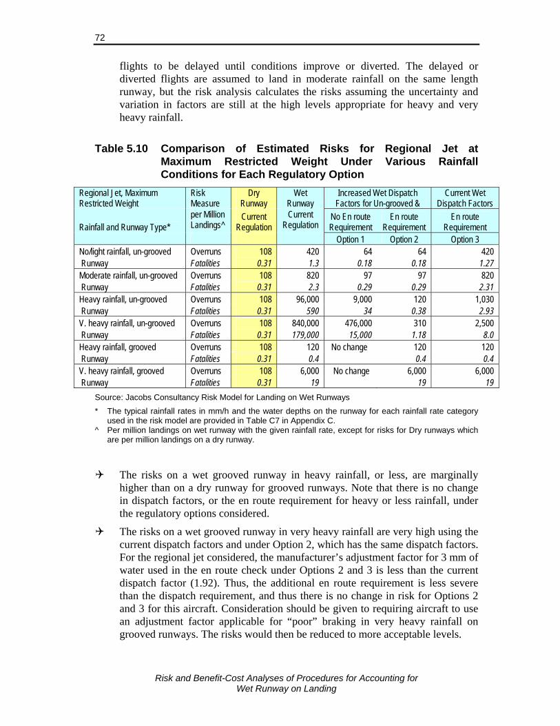
Risk and Benefit-Cost Analyses of Procedures for Accounting for
Wet Runway on Landing
72
flights to be delayed until conditions improve or diverted. The delayed or diverted flights are assumed to land in moderate rainfall on the same length runway, but the risk analysis calculates the risks assuming the uncertainty and variation in factors are still at the high levels appropriate for heavy and very heavy rainfall.
Table 5.10 Comparison of Estimated Risks for Regional Jet at
Maximum Restricted Weight Under Various Rainfall Conditions for Each Regulatory Option
Regional Jet, Maximum Restricted Weight
Risk Measure
Dry Runway
Wet Runway
Increased Wet Dispatch Factors for Un-grooved &
Current Wet Dispatch Factors
Rainfall and Runway Type* per Million Landings^
Current Regulation
Current Regulation
No En route Requirement
En route Requirement
En route Requirement
Option 1 Option 2 Option 3 No/light rainfall, un-grooved Overruns 108 420 64 64 420 Runway Fatalities 0.31 1.3 0.18 0.18 1.27 Moderate rainfall, un-grooved Overruns 108 820 97 97 820 Runway Fatalities 0.31 2.3 0.29 0.29 2.31 Heavy rainfall, un-grooved Overruns 108 96,000 9,000 120 1,030 Runway Fatalities 0.31 590 34 0.38 2.93 V. heavy rainfall, un-grooved Overruns 108 840,000 476,000 310 2,500 Runway Fatalities 0.31 179,000 15,000 1.18 8.0 Heavy rainfall, grooved Overruns 108 120 No change 120 120 Runway Fatalities 0.31 0.4 0.4 0.4 V. heavy rainfall, grooved Overruns 108 6,000 No change 6,000 6,000 Runway Fatalities 0.31 19 19 19
Source: Jacobs Consultancy Risk Model for Landing on Wet Runways
* The typical rainfall rates in mm/h and the water depths on the runway for each rainfall rate category used in the risk model are provided in Table C7 in Appendix C.
^ Per million landings on wet runway with the given rainfall rate, except for risks for Dry runways which are per million landings on a dry runway.
The risks on a wet grooved runway in heavy rainfall, or less, are marginally higher than on a dry runway for grooved runways. Note that there is no change in dispatch factors, or the en route requirement for heavy or less rainfall, under the regulatory options considered.
The risks on a wet grooved runway in very heavy rainfall are very high using the current dispatch factors and under Option 2, which has the same dispatch factors. For the regional jet considered, the manufacturer’s adjustment factor for 3 mm of water used in the en route check under Options 2 and 3 is less than the current dispatch factor (1.92). Thus, the additional en route requirement is less severe than the dispatch requirement, and thus there is no change in risk for Options 2 and 3 for this aircraft. Consideration should be given to requiring aircraft to use an adjustment factor applicable for “poor” braking in very heavy rainfall on grooved runways. The risks would then be reduced to more acceptable levels.
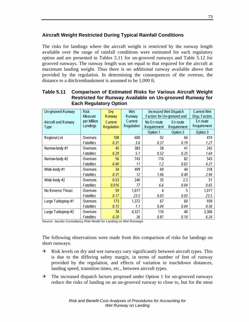
Risk and Benefit-Cost Analyses of Procedures for Accounting for
Wet Runway on Landing
73
Aircraft Weight Restricted During Typical Rainfall Conditions The risks for landings where the aircraft weight is restricted by the runway length available over the range of rainfall conditions were estimated for each regulatory option and are presented in Tables 5.11 for un-grooved runways and Table 5.12 for grooved runways. The runway length was set equal to that required for the aircraft at maximum landing weight. Thus there is no additional runway available above that provided by the regulation. In determining the consequences of the overrun, the distance to a ditch/embankment is assumed to be 1,000 ft. Table 5.11 Comparison of Estimated Risks for Various Aircraft Weight
Restricted for Runway Available on Un-grooved Runway for Each Regulatory Option
Un-grooved Runway
Risk Measure
Dry Runway
Wet Runway
Increased Wet Dispatch Factors for Un-grooved and
Current Wet Disp. Factors
Aircraft and Runway Type
per Million Landings
Current Regulation
Current Regulation
No En route Requirement
En route Requirement
En route Requirement
Option 1 Option 2 Option 3 Regional Jet Overruns 108 600 92 66 419 Fatalities 0.31 3.6 0.37 0.19 1.27 Narrow-body #1 Overruns 45 383 58 41 242 Fatalities 0.29 5.1 0.52 0.25 1.64 Narrow-body #2 Overruns 56 743 110 82 543 Fatalities 0.40 11 1.2 0.63 4.21 Wide-body #1 Overruns 34 499 69 44 318 Fatalities 0.31 12 1.06 0.40 2.94 Wide-body #2 Overruns 0.53 240 35 2.3 51 Fatalities 0.016 77 6.6 0.04 0.65 No Reverse Thrust Overruns 59 1,017 4 5 1,017 Fatalities 0.17 23.5 0.03 0.03 23.5 Large Turboprop #1 Overruns 173 1,372 67 60 939 Fatalities 0.15 1.1 0.04 0.04 0.56 Large Turboprop #2 Overruns 78 4,321 110 40 3,306 Fatalities 0.20 36 0.81 0.10 6.24
Source: Jacobs Consultancy Risk Model for Landing on Wet Runways The following observations were made from this comparison of risks for landings on short runways:
Risk levels on dry and wet runways vary significantly between aircraft types. This is due to the differing safety margin, in terms of number of feet of runway provided by the regulation, and effects of variation in touchdown distances, landing speed, transition times, etc., between aircraft types.
The increased dispatch factors proposed under Option 1 for un-grooved runways reduce the risks of landing on an un-grooved runway to close to, but for the most
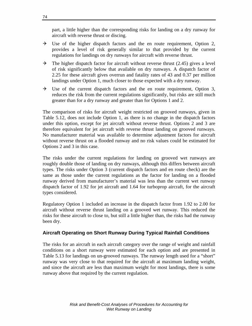
Risk and Benefit-Cost Analyses of Procedures for Accounting for
Wet Runway on Landing
74
part, a little higher than the corresponding risks for landing on a dry runway for aircraft with reverse thrust or discing.
Use of the higher dispatch factors and the en route requirement, Option 2, provides a level of risk generally similar to that provided by the current regulations for landings on dry runways for aircraft with reverse thrust.
The higher dispatch factor for aircraft without reverse thrust (2.45) gives a level of risk significantly below that available on dry runways. A dispatch factor of 2.25 for these aircraft gives overrun and fatality rates of 43 and 0.37 per million landings under Option 1, much closer to those expected with a dry runway.
Use of the current dispatch factors and the en route requirement, Option 3, reduces the risk from the current regulations significantly, but risks are still much greater than for a dry runway and greater than for Options 1 and 2.
The comparison of risks for aircraft weight restricted on grooved runways, given in Table 5.12, does not include Option 1, as there is no change in the dispatch factors under this option, except for jet aircraft without reverse thrust. Options 2 and 3 are therefore equivalent for jet aircraft with reverse thrust landing on grooved runways. No manufacturer material was available to determine adjustment factors for aircraft without reverse thrust on a flooded runway and no risk values could be estimated for Options 2 and 3 in this case. The risks under the current regulations for landing on grooved wet runways are roughly double those of landing on dry runways, although this differs between aircraft types. The risks under Option 3 (current dispatch factors and en route check) are the same as those under the current regulations as the factor for landing on a flooded runway derived from manufacturer’s material was less than the current wet runway dispatch factor of 1.92 for jet aircraft and 1.64 for turboprop aircraft, for the aircraft types considered. Regulatory Option 1 included an increase in the dispatch factor from 1.92 to 2.00 for aircraft without reverse thrust landing on a grooved wet runway. This reduced the risks for these aircraft to close to, but still a little higher than, the risks had the runway been dry. Aircraft Operating on Short Runway During Typical Rainfall Conditions The risks for an aircraft in each aircraft category over the range of weight and rainfall conditions on a short runway were estimated for each option and are presented in Table 5.13 for landings on un-grooved runways. The runway length used for a “short” runway was very close to that required for the aircraft at maximum landing weight, and since the aircraft are less than maximum weight for most landings, there is some runway above that required by the current regulation.
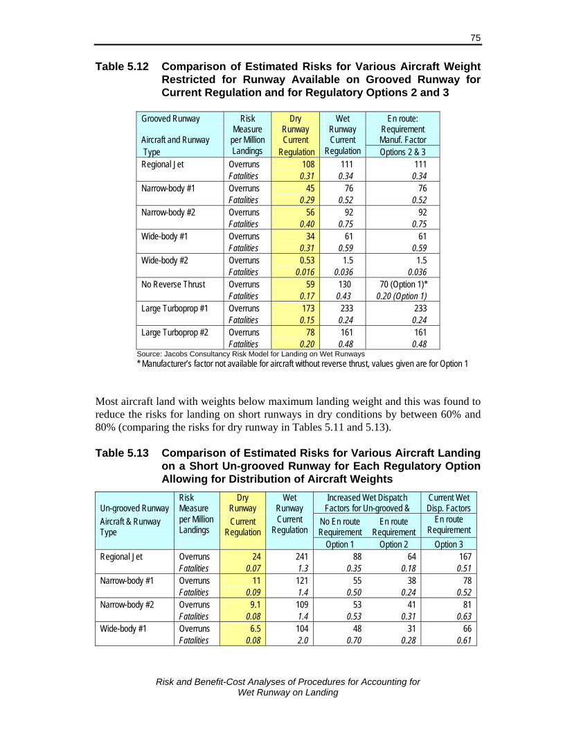
Risk and Benefit-Cost Analyses of Procedures for Accounting for
Wet Runway on Landing
75
Table 5.12 Comparison of Estimated Risks for Various Aircraft Weight Restricted for Runway Available on Grooved Runway for Current Regulation and for Regulatory Options 2 and 3
Grooved Runway Risk Dry Wet En route:
Aircraft and Runway Measure
per Million Runway Current
Runway Current
Requirement Manuf. Factor
Type Landings Regulation Regulation Options 2 & 3 Regional Jet Overruns 108 111 111 Fatalities 0.31 0.34 0.34 Narrow-body #1 Overruns 45 76 76 Fatalities 0.29 0.52 0.52 Narrow-body #2 Overruns 56 92 92 Fatalities 0.40 0.75 0.75 Wide-body #1 Overruns 34 61 61 Fatalities 0.31 0.59 0.59 Wide-body #2 Overruns 0.53 1.5 1.5 Fatalities 0.016 0.036 0.036 No Reverse Thrust Overruns 59 130 70 (Option 1)* Fatalities 0.17 0.43 0.20 (Option 1) Large Turboprop #1 Overruns 173 233 233 Fatalities 0.15 0.24 0.24 Large Turboprop #2 Overruns 78 161 161 Fatalities 0.20 0.48 0.48
Source: Jacobs Consultancy Risk Model for Landing on Wet Runways * Manufacturer’s factor not available for aircraft without reverse thrust, values given are for Option 1
Most aircraft land with weights below maximum landing weight and this was found to reduce the risks for landing on short runways in dry conditions by between 60% and 80% (comparing the risks for dry runway in Tables 5.11 and 5.13). Table 5.13 Comparison of Estimated Risks for Various Aircraft Landing
on a Short Un-grooved Runway for Each Regulatory Option Allowing for Distribution of Aircraft Weights
Un-grooved Runway Risk Measure
Dry Runway
Wet Runway
Increased Wet Dispatch Factors for Un-grooved &
Current Wet Disp. Factors
Aircraft & Runway Type
per Million Landings
Current Regulation
Current Regulation
No En route Requirement
En route Requirement
En route Requirement
Option 1 Option 2 Option 3 Regional Jet Overruns 24 241 88 64 167 Fatalities 0.07 1.3 0.35 0.18 0.51 Narrow-body #1 Overruns 11 121 55 38 78 Fatalities 0.09 1.4 0.50 0.24 0.52 Narrow-body #2 Overruns 9.1 109 53 41 81 Fatalities 0.08 1.4 0.53 0.31 0.63 Wide-body #1 Overruns 6.5 104 48 31 66 Fatalities 0.08 2.0 0.70 0.28 0.61

Risk and Benefit-Cost Analyses of Procedures for Accounting for
Wet Runway on Landing
76
Table 5.13 Comparison of Estimated Risks for Various Aircraft Landing on a Short Un-grooved Runway for Each Regulatory Option Allowing for Distribution of Aircraft Weights (Cont’d.)
Un-grooved Runway Risk Measure
Dry Runway
Wet Runway
Increased Wet Dispatch Factors for Un-grooved &
Current Wet Disp. Factors
Aircraft & Runway Type
per Million Landings
Current Regulation
Current Regulation
No En route Requirement
En route Requirement
En route Requirement
Option 1 Option 2 Option 3 Wide-body #2 Overruns 0.11 43 22 1.4 5.0 Fatalities 0.002 11 4.1 0.03 0.08 No Reverse Thrust Overruns 24 360 3.6 3.6 360 Fatalities 0.07 7.6 0.03 0.03 7.6 Large Turboprop #1 Overruns 73 350 60 240 Fatalities 0.05 0.3 0.04 0.18 Large Turboprop #2 Overruns 15 790 39 470 Fatalities 0.05 7.3 0.10 0.98
Note: Runway lengths close to that required at maximum landing weight, although aircraft are below this weight most of the time
Source: Jacobs Consultancy Risk Model for Landing on Wet Runways The risks for landing on wet runways with typical variations in landing weights are also reduced by a similar margin. Finding from comparisons of the risks under the different regulatory options are very similar, both for un-grooved and grooved (not presented in the table) runways, to those given above for landings of aircraft weight restricted by the available runway length. Summary The risk model predicts overrun rates which are consistent with historical rates, both on wet and dry, and grooved and un-grooved runways, and for aircraft with and without reverse thrust. Estimates from the model predict that:
The risk for landing during heavy rainfall on un-grooved runways under current regulations is very high and well beyond the acceptable risks in aviation.
The risks are high for landing on grooved runways during very heavy rainfall and are greater than acceptable risks in aviation.
Increasing the wet runway dispatch factors as given under regulatory Option 1 reduces the risks of landing on wet un-grooved runways to a little above those for landing on dry runways, and slightly less than those for landing on wet grooved runways, for aircraft with reverse thrust.
The dispatch factor of 2.45 under Option 1 for aircraft without reverse thrust reduces the risks to below those for a dry runway and a factor of 2.25 gives risks comparable with those on a dry runway.
The en route landing distance calculation as described under Option 2 greatly reduces the risks when landing on an un-grooved runway under heavy rainfall conditions and, overall, results in a significant reduction in the risks. Note that
Risk and Benefit-Cost Analyses of Procedures for Accounting for
Wet Runway on Landing
77
under Option 2, the adjustment factor for these rainfall conditions is applicable for “poor” braking and is typically well below that given by the manufacture’s adjustment for landing on runways with 3 to 6 mm of water.
Use of the current dispatch factors and the en route requirement, Option 3, reduces the risk from the current regulations significantly, but risks are still much greater than for a dry runway and greater than for Options 1 and 2.
The en route calculation as described under Option 2 for landing on a grooved runway typically has no effect on the risks for many aircraft as the adjustment factor based on manufacturer’s material for landing on runways with 3 to 6 mm of water is usually below the current wet runway adjustment factor.
Risk and Benefit-Cost Analyses of Procedures for Accounting for
Wet Runway on Landing
78

Risk and Benefit-Cost Analyses of Procedures for Accounting for
Wet Runway on Landing
79
6. ANALYSIS OF BENEFITS AND COSTS The benefits and costs of the alternate regulatory options were determined for a range of particular aircraft types under a range of airport and wet runway landing conditions. Calculation of overall benefits and costs would require additional data on the distribution of rainfall rates, temperatures, winds and runway characteristics at each airport and aircraft characteristics for each aircraft type operating at these airports. Overall benefit-costs were not determined for this report; however, the results presented will give a good appreciation of the benefit-costs of meeting the regulatory options outline in Section 5.2. The method used to estimate the benefits and costs for a particular aircraft type and airport is outlined in Section 6.2 with details provided in Appendix C. The analysis does not consider crosswinds or the possibility of the aircraft going off the side of the runway due to crosswinds as this is outside the scope of this study. Regulatory options considered to reduce the risk of overruns will also reduce the risks of landing on wet runways in strong crosswinds and thus improve the cost-effectiveness of the regulatory options above those given in this section. It was necessary to make a number of simplifying assumptions that could affect the benefits and costs in the practical application of any requirement. It was assumed that prior to departure the only information on whether the runway is wet, or forecast to be wet at the time of landings was used. Thus, even if the forecast is for heavy rainfall at the time of landing, it is assumed that no additional measures are taken, such as further reducing aircraft weight, delaying the departure time or canceling the flight, which specifically use of the forecast of heavy rainfall. Costs and risks may be reduced if runway conditions are known accurately and measures are taken prior to departure. However, the prediction of heavy rainfall during specific periods is not sufficiently accurate in most circumstances to make it reasonable to consider this requirement. Assumptions given in Section 6 regarding the effects of crosswinds and conditions at alternate airports also apply. The benefit-cost ratios use the current requirement of applying a 15% additional factor at the time of dispatch when the runway is wet as the base case in considering changes to the current regulation. 6.1 Calculation of Benefits The risk model described in Section 5 was used to calculate the expected number and consequences (fatalities, injuries and total cost) of overruns due to landing on wet runways. These consequences were determined under the current regulations and under each of the three regulatory options (described in Section 5.2) being investigated. The benefits of each regulatory option are then found by subtracting the consequences for each option from the consequences under current regulations. The

Risk and Benefit-Cost Analyses of Procedures for Accounting for
Wet Runway on Landing
80
dollar values of reductions fatalities and serious injuries used in determining the overall benefits are discussed in Section 6.1.1. The consequences of overrun accident/incidents, and therefore the benefits of accounting for wet runways, are dependent on the overrun areas at the airport. The benefit-cost ratios were determined for various aircraft landing situations, include both flat outrun areas and areas with an embankment, ditch or water. As discussed in Section 2.6, runway safety areas of 1,000 ft. beyond the end of the runway are recommended, although many airports have much smaller safety areas. The benefits reported here are mostly for the case where the safety area is 1,000 ft, but values are also provided for distances of 500 ft. and 50 ft. to a ditch, embankment or water. Value of Life Used in Transportation Studies Canada TC does not publish values for reducing fatalities or serious injuries for use in evaluating the benefits and costs of safety improvements. However, values have been used in a number of studies for TC evaluating aviation related projects [29, 36, 38, 39]. The most recent values used in 2003 were:
Fatality reduction $3,000,000
Serious injury reduction $850,000 These values correspond to values used in earlier benefit-cost analyses for TC with allowance for inflation. United States The U.S. Federal Aviation Administration (FAA) has established standard methods for evaluating investment and regulatory programs. These methods are described in a 2004 report, Economic Values for FAA Investment and Regulatory Decisions [40]. Section 2 of the Economic Values Report (reprinted in Appendix E) describes the FAA’s treatment of the values of life and injury in economic analysis. These values have themselves been extracted from guidance developed by the Office of the Secretary of Transportation (OST) and published in the memorandum, “Revised Departmental Guidance - Treatment of Value of Life and Injuries in Preparing Economic Evaluations”, which was issued on January 29, 2002. As stated in the Economic Values Report, the valuation of reduced risks of fatalities is accomplished by FAA using a “willingness to pay” (WTP) approach. Under this approach, life and injuries are valued in accordance with the estimated price that society is willing to pay to avoid fatalities or injuries via regulatory actions or investments that reduce the risk of such events. As stated in the Economic Values Report:
Risk and Benefit-Cost Analyses of Procedures for Accounting for
Wet Runway on Landing
81
The basic approach taken to value an avoided fatality is to determine how much an individual or group of individuals is willing to pay for a small reduction in risk. Once this amount is known, it is necessary to determine how much risk reduction is required to avoid one fatality. The total willingness to pay for the amount of risk reduction required to avoid one fatality is termed the value of life or sometimes the value of a statistical life.31
The Economic Values report then provides a simplified example of how the value of life can be estimated using the WTP approach:
For example, if people are willing to pay $3 to eliminate an incremental risk of fatality with a one in a million chance of occurrence, this implies that they would be willing as a group to pay $3 million to prevent one fatality. From another perspective, $3 million represents the amount a group as a whole would be willing to pay to purchase the risk reduction necessary to avoid one expected fatality among its members.32
As suggested above, with WTP approach it is critical for an analyst to evaluate the following two factors:
The monetary value that can be associated with a “statistical life”
The estimated reduction in risk associated with the proposed regulatory or investment action, expressed as a probability.
These two values can then be multiplied to develop the overall economic value of avoided fatalities associated with the regulatory or investment action, as expressed by the following simple equation: Value of Avoided Fatalities = Estimated Reduction in Risk * Value of Statistical Life The value of a statistical life has been established by the OST at US$3 million per fatality averted.33 As stated in the FAA’s Economic Values Report, “this US$3 million value should be used in all FAA analyses until revised by the OST.” The Canadian Transportation Safety Board in Safety Issues Investigation Report SII A05-01, “Post-Impact Fires Resulting from Small-Aircraft Accident”, refers to the US Department of Transport and FAA value of life of US$3 million and states that this value is low relative to recent empirical estimates. Other Countries The UK Civil Aviation Authority, similar to the United States FAA and DOT, uses a “willingness-to-pay” (WTP) approach for the value of life in aviation cost benefit studies. The value of life for deaths in aviation accidents is taken by the Department
31 p. 2-1. of [42] 32 Ibid. 33 This value, estimated by the OST in 2002, is expressed in 2001 dollars. Per FAA and OST policy,
the value is not escalated to account for inflation until officially escalated by OST.

Risk and Benefit-Cost Analyses of Procedures for Accounting for
Wet Runway on Landing
82
for Transport (DoT) as being the same as that in road accidents [41]. The value of life for a fatality used in 2004 was £1,246,000 ($ 2,854,000).34 The UK Department of Transport updates its estimates of the average value of prevention per casualty for fatal and non-fatal casualties each year. The latest valuations for 2005 were as follow [42]:
Fatality £1,428,180 ($3,271,000 at current exchange rate)
Serious injury £160,480 ($367,500)
Slight injury £12,370 ($28,300) In Australia, the Bureau of Transport Economics does not use a WTP approach for the value of life. Instead, the Bureau estimates the direct cost of accidents related to personal injury – loss of output, loss of quality of life, medical costs and coronial, funeral, legal and prison costs. Its estimate for the costs for a fatal road injury in 1996 was A$1.5 million ($1.42 million35) and A$325,000 ($310,000) for a serious injury [43]. The loss of quality of life is based on the compensation paid to crash victims. In Australia compensation paid is subject to upper limits set by government insurers or court settlements. These mechanisms would differ from country to country. The Bureau also discusses the WTP approach and notes that valuations in a number of countries are typically in the range of A$1.8 to A$4.2 million ($1.7 to $4.0 million). The Bureau conducted a study of the cost of civil aviation accidents in 2003 and 2004 and estimated that the cost attributable to each fatality was A$2.17 million ($2.06 million) [44]. The Bureau also noted that there are a small number of occurrence per annum and large fluctuations year to year. Values of Life and Serious Injury Prevented Used in Analysis The values for the prevention of fatalities and serious injuries from these studies were adjusted for inflation since the study. The values used in the risk and benefit-cost analyses are provided in Table 6.1. Unless otherwise stated, the average values of $3.4 million per fatality reduction and $0.7 million per serious injury were used in the benefit-cost analyses.
34 Exchange rate used £1.00 = C$2.29. 35 Exchange rate used A$1.00 = C$0.95.
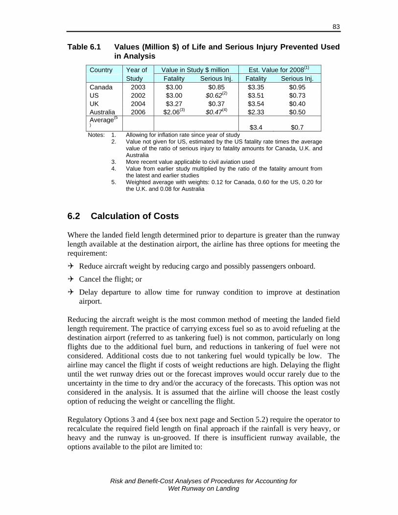
Risk and Benefit-Cost Analyses of Procedures for Accounting for
Wet Runway on Landing
83
Table 6.1 Values (Million $) of Life and Serious Injury Prevented Used in Analysis
Country Year of Value in Study $ million Est. Value for 2008(1) Study Fatality Serious Inj. Fatality Serious Inj. Canada 2003 $3.00 $0.85 $3.35 $0.95 US 2002 $3.00 $0.62(2) $3.51 $0.73 UK 2004 $3.27 $0.37 $3.54 $0.40 Australia 2006 $2.06(3) $0.47(4) $2.33 $0.50 Average(5
) $3.4 $0.7 Notes: 1. Allowing for inflation rate since year of study 2. Value not given for US, estimated by the US fatality rate times the average
value of the ratio of serious injury to fatality amounts for Canada, U.K. and Australia
3. More recent value applicable to civil aviation used 4. Value from earlier study multiplied by the ratio of the fatality amount from
the latest and earlier studies 5. Weighted average with weights: 0.12 for Canada, 0.60 for the US, 0.20 for
the U.K. and 0.08 for Australia
6.2 Calculation of Costs Where the landed field length determined prior to departure is greater than the runway length available at the destination airport, the airline has three options for meeting the requirement:
Reduce aircraft weight by reducing cargo and possibly passengers onboard.
Cancel the flight; or
Delay departure to allow time for runway condition to improve at destination airport.
Reducing the aircraft weight is the most common method of meeting the landed field length requirement. The practice of carrying excess fuel so as to avoid refueling at the destination airport (referred to as tankering fuel) is not common, particularly on long flights due to the additional fuel burn, and reductions in tankering of fuel were not considered. Additional costs due to not tankering fuel would typically be low. The airline may cancel the flight if costs of weight reductions are high. Delaying the flight until the wet runway dries out or the forecast improves would occur rarely due to the uncertainty in the time to dry and/or the accuracy of the forecasts. This option was not considered in the analysis. It is assumed that the airline will choose the least costly option of reducing the weight or cancelling the flight. Regulatory Options 3 and 4 (see box next page and Section 5.2) require the operator to recalculate the required field length on final approach if the rainfall is very heavy, or heavy and the runway is un-grooved. If there is insufficient runway available, the options available to the pilot are limited to:

Risk and Benefit-Cost Analyses of Procedures for Accounting for
Wet Runway on Landing
84
Delay landing to allow time for the rainfall rate and depth of water on the runway to decline;
Divert to the alternate airport; or
Reduce landing weight by dumping or burning fuel. Diverting to the alternate airport may not always be a good option as the rain storm may also be affecting the alternate airport. It may be necessary to divert to another more distant airport not affected by the storm or which has a longer runway. Reducing landing weight by dumping fuel is rare, except in emergencies, and was not considered in the analysis. The costs for meeting the en route landing distance requirement were determined assuming the pilot takes the least costly option of delaying or diverting the flight. Delay time required for the heavy rainfall to abate will vary greatly in practice, but the pilot will often be able to obtain forecasts of the time until the rainfall abate. Periods of heavy rainfall are usually short, typically lasting less than an hour, and very heavy rainfall even shorter. The calculation of the costs associated with each of these options is described below. Parameters related to each aircraft type used in the calculation of these costs are presented in Table 6.2.
Table 6.2 Aircraft Parameters Used in Calculation of Costs
Aircraft Type No. of Pass. Seats
No. of Crew
Crew cost per
hr
Aircraft Block Hour
Cost
Aircraft Replacement Value ($M)
CRJ-100/200 50 4 $243 $1,484 $14.51 B737-300 132 5 $540 $3,205 $9.19 B767-200ER 190 7 $639 $4,604 $42.42 A320-200 140 6 $468 $3,163 $37.55 A340-300 295 9 $962 $6,612 $102.80 DHC8-100 37 3 $235 $1,456 $6.14 DHC8-400 74 4 $343 $2,094 $15.87
Sources: No. of passengers and crew – OAG and Airlines web sites (varies by airline).
Crew and block hour costs, US DoT Carrier Form 41 Reports Aircraft Replacement Value – The Aircraft Value Company, Oct.,
2007. Aircraft Weight Reduction The landing weight could be reduced prior to departure by carrying less cargo, fewer passengers, or possibly less fuel. Reductions in aircraft weight while en route, other than expected fuel burn, were not considered.

Risk and Benefit-Cost Analyses of Procedures for Accounting for
Wet Runway on Landing
85
The amount of cargo carried on commercial passenger flights typically varies from zero to 10% of the landing weight. The distribution of cargo weights is not readily available and for the purposes of this analysis, benefit-cost ratios were determined for the two cases where the weight reduction could be achieved entirely by (i) off-loading cargo, and (ii) off-loading passengers. Off-loading Cargo The penalty for removing cargo is assumed to depend on the revenue generated by the cargo on the flight segment. In many situations, the cargo could be sent on a later flight or a road feeder service at no penalty. In other cases, the shipments may be subject to delivery guarantees, very time sensitive (e.g., replacement machine parts) or could be perishable. A delayed shipment could then alienate a valuable customer, with a substantial loss of good will and future revenue. Given these variations in the urgency and costs of removing cargo, the average penalty is estimated by the estimated average revenue from the off-loaded cargo. The estimate is based on the typical yield per tonne-kilometer plus a fixed handling cost per kilogram. Details are given in Appendix D. The costs ranged from $320 per tonne for short flights of 600 km to $1800 per tonne for long flights of 8,000 km Off-loading Passengers Passengers will be displaced only if the aircraft still exceeds its allowed landing weight after all air freight has been removed. Enough passengers will then be denied boarding so as to meet the wet runway constraints. An average weight per passenger (including luggage) of 100 kg is used. It is assumed that the carrier uses the “auction” method of off-loading passengers where the carriers pays more flexible passengers to surrender their seats on the flight and take a later flight. There is no publicly available information in Canada on the average amount of the compensation and, based on the consultants experience, it was assumed to equal the average one-way fare, excluding taxes and airport charges, for a typical flight distance for the aircraft being off-loaded. The method used to estimate the one-way fares in the analysis is provided in Appendix D. The costs ranged from $186 per passenger for short flights of 600 km to $1,000 per passenger for long flights of 8,000 km. The costs of off-loading passengers were five to six times greater than off-loading cargo. Cancelled Flight Flights are rarely cancelled due to forecasts of wet runway conditions at the destination airport. Airlines indicated they are reluctant to cancel flights if conditions may improve and allow the flight to land. It is assumed airlines would only consider cancelling a flight if heavy rain was expected at the destination airport where the runway is un-grooved, or for very heavy rain where the runway is grooved. In these
Risk and Benefit-Cost Analyses of Procedures for Accounting for
Wet Runway on Landing
86
cases, the flight would be cancelled only of the cost to reduce aircraft weight to the regulated level is greater than the cost of canceling the flight. The costs for cancelled flights are difficult to estimate. Direct airline operating costs will be less than for diverted flights, but long-term costs related to their reputation for reliability would be affected and this is difficult to quantify. For cancelled flights it is assumed that the costs to passengers will be double those for a diverted flight (i.e., $150, equivalent to a six hour delay), but that there will be no additional crew and flying costs and little impact on downstream costs (a one hour delay was used). Since the cancellation of the flight would be for factors beyond the carrier’s control, there would be no monetary compensation offered to passengers and they would be allowed to travel on a flight at a later time. Delay Landing at Airport Periods of heavy rainfall are usually short, typically lasting less than an hour, and very heavy rainfall even shorter. The analysis included three delay times, 20, 40 and 60 minutes, and assumed a probability that the rainfall abates in each of those time period of:
0.275 for change from very heavy to heavy or less (applicable for grooved runway)
0.20 from heavy or very heavy to moderate or less (applicable for un-grooved runway)
Delaying the flight for the runway condition to improve will only be feasible for a portion of the flights, even if this is the least costly option. For other flights that would not benefit from a delay, the flight is assumed to be diverted. The probability that flights would not be delay, but be diverted, is 0.4 [1-3 x 0.2] given heavy rainfall is encountered on final approach to an un-grooved runway, and 0.175 [1-3 x 0.275] given very heavy rainfall is encountered on final approach to a grooved runway. These probabilities are only approximate as accurate data on the duration of transient rainfall could not be obtained.36 The cost of delaying the flight while en route was determined based on the additional aircraft operating costs, the costs of downstream delays and the value of passenger delay time. The downstream cost is the least known of the costs, but for long delays it is the greatest component of the costs. Downstream delays were estimated by summing the delay cost for successive flights following the originally delayed flight, assuming that it is possible to make up 15 minutes on each flight. The 15 minutes is typical for most
36 Environment Canada records hourly rainfall data, but this does not give accurate rates for heavy
rainfall periods less than an hour, or when the heavy rainfall spans several clock-hour periods. Values used were estimated using data for Seattle, Chicago, Santa Fe and New Orleans.

Risk and Benefit-Cost Analyses of Procedures for Accounting for
Wet Runway on Landing
87
operations.37 No additional delay costs are added when the flight is the last flight of the day and it is assumed that by the next morning the flights are back on schedule. An average of six flights per day is assumed and the initially delayed flight could be any one of the six flights. The downstream costs were estimated using this approach, and are illustrated in Figure 6.1 for delays to B767, A320 and CRJ aircraft. These downstream costs do not consider costs to flights by other aircraft that may be affected by the delay and are therefore likely conservative. Functions for estimating the costs are provided in Appendix D.
$0$5,000
$10,000$15,000$20,000$25,000$30,000$35,000$40,000$45,000$50,000
0.0 0.5 1.0 1.5 2.0 2.5 3.0 3.5 4.0
Delay Time (hrs)
CRJ A320 B767
B767
A320
CRJ
Figure 6.1 Downstream Costs versus Delay Time for B767, A320 and CRJ Aircraft
Diversion to Alternate Airport The costs for flights diverted to another airport are estimated considering the delays to the passengers and crew and the downstream effects. The additional flight time to an alternate airport will typically be around 30-45 minutes and this represents an additional cost associated with flying the aircraft. On arrival at the alternate airport the aircraft could wait until conditions have improved then go on to the original destination, or make ground travel arrangements for the passengers and return the aircraft to its planned schedule. In the latter case the passengers who would have boarded at the original destination airport will no longer be able to do so. An example of the types of costs that would be involved in both options for a typical short haul flight are given in Table 6.3. It is assumed that there is a total delay of 3 hours when the aircraft diverts and proceeds to the destination once conditions have improved. Where the flight does not continue most of the cost is related to the delay time to passengers (assumed to be 6 hours) and the cost of the alternative transport by bus 37 The time period between scheduled arrival and departure has been reduced in recent years to
improve aircraft utilization, but this has made it more difficult to make up time once a flight has been delayed.
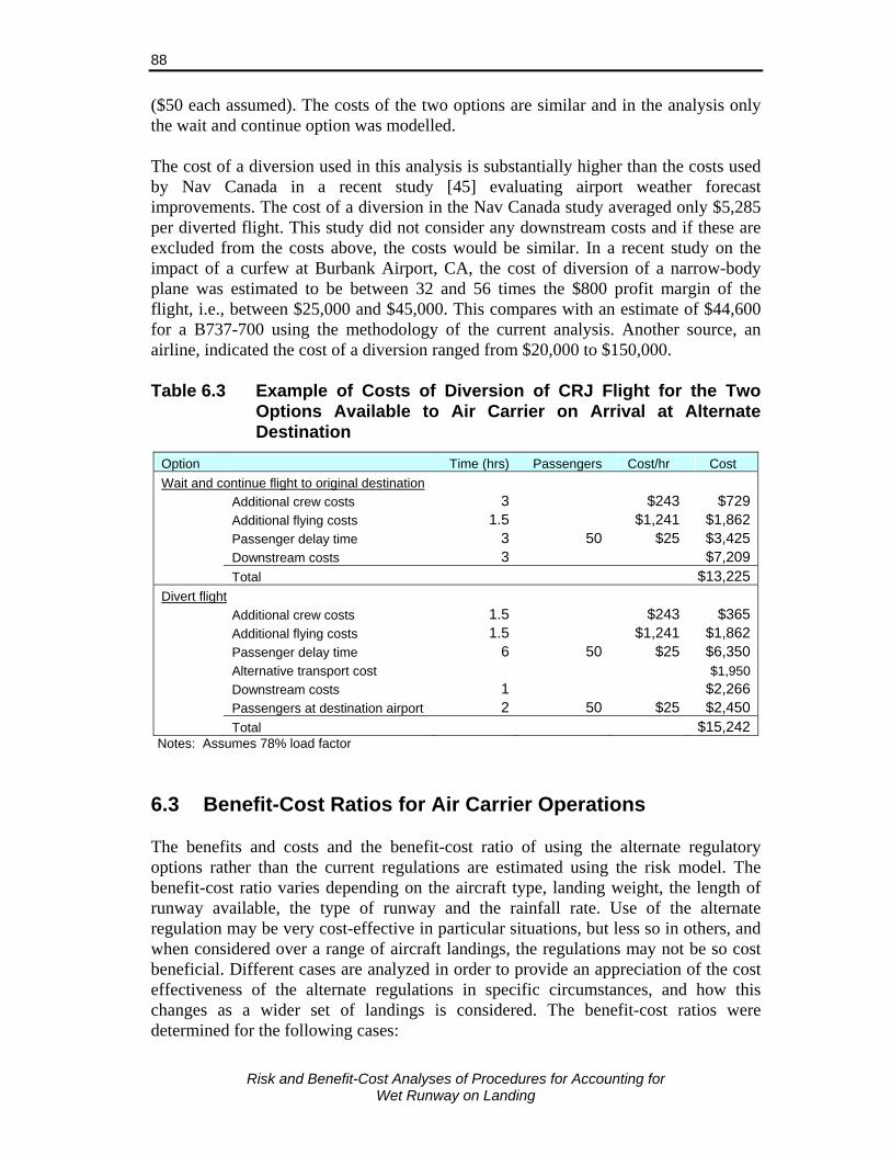
Risk and Benefit-Cost Analyses of Procedures for Accounting for
Wet Runway on Landing
88
($50 each assumed). The costs of the two options are similar and in the analysis only the wait and continue option was modelled. The cost of a diversion used in this analysis is substantially higher than the costs used by Nav Canada in a recent study [45] evaluating airport weather forecast improvements. The cost of a diversion in the Nav Canada study averaged only $5,285 per diverted flight. This study did not consider any downstream costs and if these are excluded from the costs above, the costs would be similar. In a recent study on the impact of a curfew at Burbank Airport, CA, the cost of diversion of a narrow-body plane was estimated to be between 32 and 56 times the $800 profit margin of the flight, i.e., between $25,000 and $45,000. This compares with an estimate of $44,600 for a B737-700 using the methodology of the current analysis. Another source, an airline, indicated the cost of a diversion ranged from $20,000 to $150,000. Table 6.3 Example of Costs of Diversion of CRJ Flight for the Two
Options Available to Air Carrier on Arrival at Alternate Destination
Option Time (hrs) Passengers Cost/hr Cost Wait and continue flight to original destination Additional crew costs 3 $243 $729 Additional flying costs 1.5 $1,241 $1,862 Passenger delay time 3 50 $25 $3,425 Downstream costs 3 $7,209 Total $13,225Divert flight Additional crew costs 1.5 $243 $365 Additional flying costs 1.5 $1,241 $1,862 Passenger delay time 6 50 $25 $6,350 Alternative transport cost $1,950 Downstream costs 1 $2,266 Passengers at destination airport 2 50 $25 $2,450 Total $15,242
Notes: Assumes 78% load factor 6.3 Benefit-Cost Ratios for Air Carrier Operations The benefits and costs and the benefit-cost ratio of using the alternate regulatory options rather than the current regulations are estimated using the risk model. The benefit-cost ratio varies depending on the aircraft type, landing weight, the length of runway available, the type of runway and the rainfall rate. Use of the alternate regulation may be very cost-effective in particular situations, but less so in others, and when considered over a range of aircraft landings, the regulations may not be so cost beneficial. Different cases are analyzed in order to provide an appreciation of the cost effectiveness of the alternate regulations in specific circumstances, and how this changes as a wider set of landings is considered. The benefit-cost ratios were determined for the following cases:

Risk and Benefit-Cost Analyses of Procedures for Accounting for
Wet Runway on Landing
89
Regional jet at maximum landing weight, the runway length available equal to that required under the current regulations, specific rainfall rates, runway un-grooved and a ditch 1,000 ft. beyond end of runway;
Aircraft at maximum landing weight, the runway length available equal to that required under the current regulations, typical variation in rainfall rates in Canada and a ditch 1,000 ft. beyond end of runway – values provided for both grooved and un-grooved runways; and
Typical variation in rainfall rates in Canada, aircraft weights vary according to the typical distribution for that aircraft type, values provided for grooved and un-grooved runways, for two cases of runway lengths available and a ditch beyond end of runway at 50, 500 and 1000 ft.
The benefits and costs for each of these cases are presented for each regulatory option (see box and Section 5.2).
Option 1. Increased Dispatch Factors & No En Route Requirement
The wet runway landing distance dispatch factor be set as follows: Grooved or PFC Other Runways Runways • Jet without reverse thrust 2.00 2.45 • Jet with reverse thrust 1.92 2.10 • Turbopropeller aircraft 1.64 1.90
Option 2. Increased Dispatch Factors Plus En Route Requirement
Use of the same dispatch factors as under Option 1 above and the requirement that at the commencement of final approach, if:
a) The runway is un-grooved and the depth of water on the runway is greater than 3 mm or if rainfall at the airport is reported as heavy, the required landing distance must be recalculated assuming the runway is flooded (i.e., water depth greater than 3 mm) and the braking is “poor” using manufacturer’s guidance material, or
b) The runway is grooved or PFC and the depth of water on the runway is greater than 3 mm or if rainfall at the airport is reported as very heavy, the required landing distance must be recalculated assuming the runway is flooded using manufacturer’s guidance material.
If the calculated distance is less than the runway length available, the pilot must not attempt to land, except in emergency situations.
Option 3. Current Dispatch Factors with En Route Requirement
Wet runway dispatch factors the same as under current regulations (1.92 for jet and 1.64 for turboprop aircraft) and the en route requirement at the commencement of final approach the same as under Option 2 above.

Risk and Benefit-Cost Analyses of Procedures for Accounting for
Wet Runway on Landing
90
Heavy Rainfall and No Additional Safety Margin above Current Regulations Table 6.4 gives the estimated benefits and costs per 1,000 landings of a regional jet on a wet un-grooved runway for each regulation for the case where the runway distance available is equal to that required under the current regulations and there is a ditch 1,000 ft. beyond the end of the runway. Values are given for two rainfall rates, light and heavy, and assuming weight reduction prior to take-off can be met by removing cargo. The table gives a breakdown of the costs and numbers of aircraft affected. During heavy rainfall for 1,000 landings in these situations, 96 would be expected to overrun the runway with and result in 0.59 fatalities, 1.8 injuries and $47.39 million in damage to the aircraft, giving a total cost of $50.64 million. With the increased dispatch factors under regulatory Option 1, the number of overruns per 1,000 landings is reduced to 9.2 with an estimated 0.034 fatalities, 0.1 injuries, $3.378 million in aircraft damage, for a total cost of $3.564 million. Thus, Option 1 is estimated to reduce the accident costs by $47.076 million per 1,000 landings in these situations. The additional costs to the airline and passengers are given relative to the current regulations and are therefore zero for the current regulations. For the case being examined, all aircraft are affected by the increased dispatch factor under Option 1 and meet the requirement by reducing weight by removing cargo. This is estimated to cost $925,604. For the heavy rainfall weight restricted situation considered, the accident benefits of Option 1 exceed the additional costs by $46.15 million per 1,000 landings and the benefit-cost ratio is 51. Inclusion of the en route requirement in addition to the increased dispatch factors under regulatory Option 2 reduces the overrun rate further down to just 0.12 and accident costs to $0.42 million per 1,000 landings in heavy rainfall. However, the additional airline and passenger costs are high, particularly of diversions, resulting in total costs of $13.3 million. Benefits exceed costs by $37.28 million per 1,000 flights and the benefit-cost ratio is 3.8 relative to current regulations for the heavy rainfall, weight restricted situation considered. Option 3, where current dispatch factors with an en route check is required, results in more overruns than Option 2, but reduced airline and passenger costs, and has a benefit-cost ratio of 4.1 for the heavy rainfall, weight restricted situation considered. In light rainfall, the numbers of overruns and overrun costs are greatly reduced by the increase in the dispatch factor, but the additional airline and passenger cost remain the same resulting in an increase in net costs and a benefit-cost ratio of 0.13 in the weight restricted situation considered. Note that regulatory Options 2 and 3 do not require the runway be treated as flooded in the en route check for light rainfall and there is no change operations. Thus for light rainfall, Option 2 is equivalent to Option 1, and Option 3 is equivalent to the current regulation.
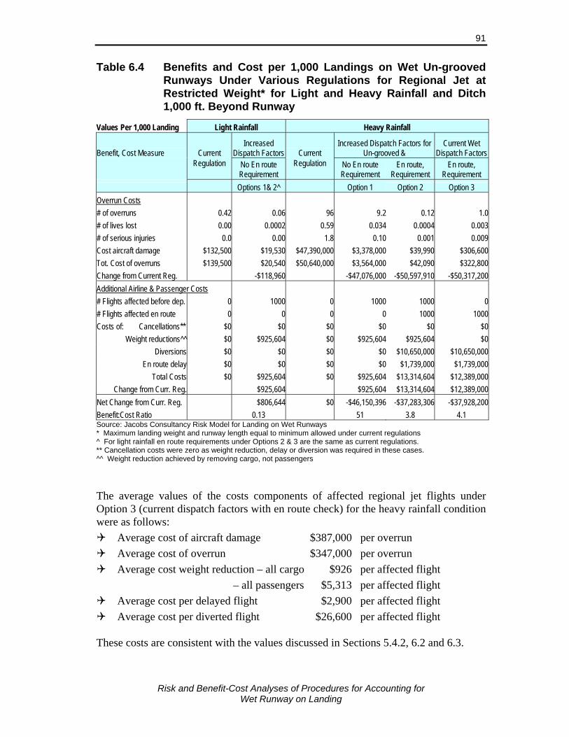
Risk and Benefit-Cost Analyses of Procedures for Accounting for
Wet Runway on Landing
91
Table 6.4 Benefits and Cost per 1,000 Landings on Wet Un-grooved Runways Under Various Regulations for Regional Jet at Restricted Weight* for Light and Heavy Rainfall and Ditch 1,000 ft. Beyond Runway
Values Per 1,000 Landing Light Rainfall Heavy Rainfall
Benefit, Cost Measure Current Increased
Dispatch Factors Current Increased Dispatch Factors for
Un-grooved & Current Wet
Dispatch Factors
Regulation No En route
Requirement Regulation No En route
Requirement En route,
Requirement En route,
Requirement Options 1& 2^ Option 1 Option 2 Option 3 Overrun Costs # of overruns 0.42 0.06 96 9.2 0.12 1.0 # of lives lost 0.00 0.0002 0.59 0.034 0.0004 0.003 # of serious injuries 0.0 0.00 1.8 0.10 0.001 0.009 Cost aircraft damage $132,500 $19,530 $47,390,000 $3,378,000 $39,990 $306,600 Tot. Cost of overruns $139,500 $20,540 $50,640,000 $3,564,000 $42,090 $322,800 Change from Current Reg. -$118,960 -$47,076,000 -$50,597,910 -$50,317,200 Additional Airline & Passenger Costs # Flights affected before dep. 0 1000 0 1000 1000 0 # Flights affected en route 0 0 0 0 1000 1000 Costs of: Cancellations** $0 $0 $0 $0 $0 $0
Weight reductions^^ $0 $925,604 $0 $925,604 $925,604 $0 Diversions $0 $0 $0 $0 $10,650,000 $10,650,000
En route delay $0 $0 $0 $0 $1,739,000 $1,739,000 Total Costs $0 $925,604 $0 $925,604 $13,314,604 $12,389,000
Change from Curr. Reg. $925,604 $925,604 $13,314,604 $12,389,000 Net Change from Curr. Reg. $806,644 $0 -$46,150,396 -$37,283,306 -$37,928,200 Benefit:Cost Ratio 0.13 51 3.8 4.1 Source: Jacobs Consultancy Risk Model for Landing on Wet Runways * Maximum landing weight and runway length equal to minimum allowed under current regulations ^ For light rainfall en route requirements under Options 2 & 3 are the same as current regulations. ** Cancellation costs were zero as weight reduction, delay or diversion was required in these cases. ^^ Weight reduction achieved by removing cargo, not passengers The average values of the costs components of affected regional jet flights under Option 3 (current dispatch factors with en route check) for the heavy rainfall condition were as follows:
Average cost of aircraft damage $387,000 per overrun Average cost of overrun $347,000 per overrun Average cost weight reduction – all cargo $926 per affected flight
– all passengers $5,313 per affected flight Average cost per delayed flight $2,900 per affected flight Average cost per diverted flight $26,600 per affected flight
These costs are consistent with the values discussed in Sections 5.4.2, 6.2 and 6.3.
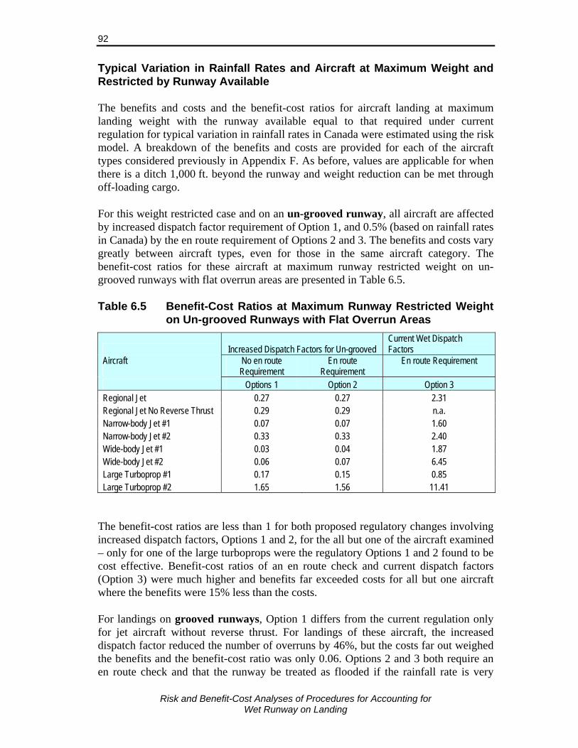
Risk and Benefit-Cost Analyses of Procedures for Accounting for
Wet Runway on Landing
92
Typical Variation in Rainfall Rates and Aircraft at Maximum Weight and Restricted by Runway Available The benefits and costs and the benefit-cost ratios for aircraft landing at maximum landing weight with the runway available equal to that required under current regulation for typical variation in rainfall rates in Canada were estimated using the risk model. A breakdown of the benefits and costs are provided for each of the aircraft types considered previously in Appendix F. As before, values are applicable for when there is a ditch 1,000 ft. beyond the runway and weight reduction can be met through off-loading cargo. For this weight restricted case and on an un-grooved runway, all aircraft are affected by increased dispatch factor requirement of Option 1, and 0.5% (based on rainfall rates in Canada) by the en route requirement of Options 2 and 3. The benefits and costs vary greatly between aircraft types, even for those in the same aircraft category. The benefit-cost ratios for these aircraft at maximum runway restricted weight on un-grooved runways with flat overrun areas are presented in Table 6.5. Table 6.5 Benefit-Cost Ratios at Maximum Runway Restricted Weight
on Un-grooved Runways with Flat Overrun Areas
Increased Dispatch Factors for Un-grooved Current Wet Dispatch Factors
Aircraft
No en route Requirement
En route Requirement
En route Requirement
Options 1 Option 2 Option 3 Regional Jet 0.27 0.27 2.31 Regional Jet No Reverse Thrust 0.29 0.29 n.a. Narrow-body Jet #1 0.07 0.07 1.60 Narrow-body Jet #2 0.33 0.33 2.40 Wide-body Jet #1 0.03 0.04 1.87 Wide-body Jet #2 0.06 0.07 6.45 Large Turboprop #1 0.17 0.15 0.85 Large Turboprop #2 1.65 1.56 11.41
The benefit-cost ratios are less than 1 for both proposed regulatory changes involving increased dispatch factors, Options 1 and 2, for the all but one of the aircraft examined – only for one of the large turboprops were the regulatory Options 1 and 2 found to be cost effective. Benefit-cost ratios of an en route check and current dispatch factors (Option 3) were much higher and benefits far exceeded costs for all but one aircraft where the benefits were 15% less than the costs. For landings on grooved runways, Option 1 differs from the current regulation only for jet aircraft without reverse thrust. For landings of these aircraft, the increased dispatch factor reduced the number of overruns by 46%, but the costs far out weighed the benefits and the benefit-cost ratio was only 0.06. Options 2 and 3 both require an en route check and that the runway be treated as flooded if the rainfall rate is very

Risk and Benefit-Cost Analyses of Procedures for Accounting for
Wet Runway on Landing
93
heavy. However, the adjustment factor for flooded (3-6 mm water) runways from the manufacture’s guidance material is usually less than the current wet runway dispatch factor (1.92) and few if any landings are affected. In the analysis, no landings were affected for the aircraft examined and benefit-costs could not be determined. Typical Variation in Rainfall Rates and Aircraft Weight for Range of Runway Lengths Aircraft rarely operate with landing weight restricted by the runway length available. Thus, there is typically a significant margin of safety available for landing. This margin affects the numbers of aircraft that will be impacted by the alternate regulations and the benefit-costs of the requirements. Table 6.6 summaries the estimated benefit-cost ratios and numbers of flights affected for each of the regulatory options for landings on wet un-grooved runways for typical ranges of aircraft weights and rainfall rates. Values are given for the short and medium length runways for the particular aircraft type. For the “short” runway case, the runway length available is equal or very close to that required by current regulations when the aircraft is a maximum landing weight. For the “medium” runway case, there is an additional 1,000-1,200 ft. available. Note that since the aircraft is usually below maximum weight there is additional runway available above this for most landings. Where more than 2,000 ft. of additional runway is available, almost no flights would be affected and the benefit-cost ratios are of no relevance (and could not be calculated). The following observations were made from the results of this analysis:
The benefit-cost ratios for aircraft at typical weights are less than the ratios for when the landing weight is restricted by the runway length available (comparing values for 0-100 ft. additional runway and ditch at 1,000 ft. in Table 6.6 with values in Table F1 of Appendix F).
The benefit-cost ratios decrease as the runway length available increases.
A high percentage of flights are affected by the increased dispatch factors for landings on short runways for that aircraft type (i.e., little or no additional runway above that required by the aircraft at maximum weight under current regulations), but with 1,000-1,200 ft. of additional runway available, very few flights will likely be affected (except for aircraft without reverse thrust).
The benefit-cost ratios double, approximately, when the distance to a ditch/embankment in the overrun area is reduced from 1,000 to 500 ft. When the ditch/embankment is 50 ft. beyond the runway, the benefit-cost ratio increases greatly to between 5 and 20 times the ratio for a ditch/embankment at 500 ft.
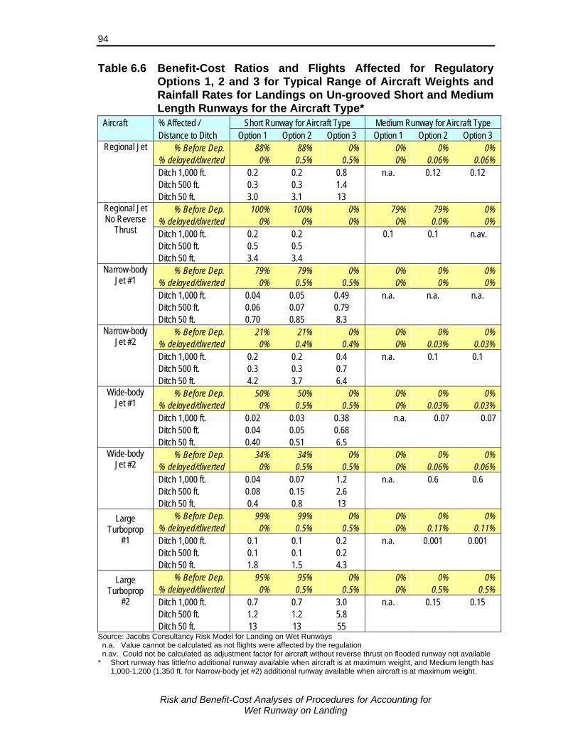
Risk and Benefit-Cost Analyses of Procedures for Accounting for
Wet Runway on Landing
94
Table 6.6 Benefit-Cost Ratios and Flights Affected for Regulatory Options 1, 2 and 3 for Typical Range of Aircraft Weights and Rainfall Rates for Landings on Un-grooved Short and Medium Length Runways for the Aircraft Type*
Aircraft % Affected / Short Runway for Aircraft Type Medium Runway for Aircraft Type Distance to Ditch Option 1 Option 2 Option 3 Option 1 Option 2 Option 3
% Before Dep. 88% 88% 0% 0% 0% 0% % delayed/diverted 0% 0.5% 0.5% 0% 0.06% 0.06%
Regional Jet
Ditch 1,000 ft. 0.2 0.2 0.8 n.a. 0.12 0.12 Ditch 500 ft. 0.3 0.3 1.4 Ditch 50 ft. 3.0 3.1 13
% Before Dep. 100% 100% 0% 79% 79% 0% % delayed/diverted 0% 0% 0% 0% 0.0% 0% Ditch 1,000 ft. 0.2 0.2 0.1 0.1 n.av.
Regional Jet No Reverse
Thrust Ditch 500 ft. 0.5 0.5
Ditch 50 ft. 3.4 3.4 % Before Dep. 79% 79% 0% 0% 0% 0%
% delayed/diverted 0% 0.5% 0.5% 0% 0% 0% Narrow-body
Jet #1 Ditch 1,000 ft. 0.04 0.05 0.49 n.a. n.a. n.a.
Ditch 500 ft. 0.06 0.07 0.79 Ditch 50 ft. 0.70 0.85 8.3
% Before Dep. 21% 21% 0% 0% 0% 0% % delayed/diverted 0% 0.4% 0.4% 0% 0.03% 0.03%
Narrow-body Jet #2
Ditch 1,000 ft. 0.2 0.2 0.4 n.a. 0.1 0.1 Ditch 500 ft. 0.3 0.3 0.7 Ditch 50 ft. 4.2 3.7 6.4
% Before Dep. 50% 50% 0% 0% 0% 0% % delayed/diverted 0% 0.5% 0.5% 0% 0.03% 0.03%
Wide-body Jet #1
Ditch 1,000 ft. 0.02 0.03 0.38 n.a. 0.07 0.07 Ditch 500 ft. 0.04 0.05 0.68 Ditch 50 ft. 0.40 0.51 6.5
% Before Dep. 34% 34% 0% 0% 0% 0% % delayed/diverted 0% 0.5% 0.5% 0% 0.06% 0.06%
Wide-body Jet #2
Ditch 1,000 ft. 0.04 0.07 1.2 n.a. 0.6 0.6 Ditch 500 ft. 0.08 0.15 2.6 Ditch 50 ft. 0.4 0.8 13
% Before Dep. 99% 99% 0% 0% 0% 0% % delayed/diverted 0% 0.5% 0.5% 0% 0.11% 0.11%
Large Turboprop
#1 Ditch 1,000 ft. 0.1 0.1 0.2 n.a. 0.001 0.001 Ditch 500 ft. 0.1 0.1 0.2 Ditch 50 ft. 1.8 1.5 4.3
% Before Dep. 95% 95% 0% 0% 0% 0% % delayed/diverted 0% 0.5% 0.5% 0% 0.5% 0.5%
Large Turboprop
#2 Ditch 1,000 ft. 0.7 0.7 3.0 n.a. 0.15 0.15 Ditch 500 ft. 1.2 1.2 5.8 Ditch 50 ft. 13 13 55
Source: Jacobs Consultancy Risk Model for Landing on Wet Runways n.a. Value cannot be calculated as not flights were affected by the regulation n.av. Could not be calculated as adjustment factor for aircraft without reverse thrust on flooded runway not available
* Short runway has little/no additional runway available when aircraft is at maximum weight, and Medium length has 1,000-1,200 (1,350 ft. for Narrow-body jet #2) additional runway available when aircraft is at maximum weight.

Risk and Benefit-Cost Analyses of Procedures for Accounting for
Wet Runway on Landing
95
For Options 1 and 2 and with little or no additional runway available, the benefit-cost ratio vary between 0.02 and 0.2 for a ditch/embankment at 1,000 ft, except for large turboprop #2 where the ratio is 0.7 for both options. With a ditch/embankment at 50 ft, benefits exceed costs for five of the eight aircraft examined and in most cases greatly exceed the costs. For two aircraft, the ratio was higher for Option 1 than for Option 2, while for the other five aircraft Option 2 was more cost-beneficial. (Comparisons could not be made for the aircraft with reverse thrust).
The benefit-cost ratio was higher for Option 3 than for Options 1 and 2 for all of the seven aircraft examined. In all cases benefits exceeded costs where there was a ditch/embankment 50 ft. beyond the runway and in all but one case the ratio was above 0.5 with a ditch/embankment 500 ft.
Off-loading Passengers Instead of Cargo The benefit-cost ratios given above are for when it is possible to reduce aircraft weight prior to take-off to satisfy the higher dispatch factor requirement of Option 1 by off-loading cargo. This is often the case as the requirement will usually only affect aircraft at close to maximum weight and most aircraft are a 5% to 10% below maximum weight with a full load of passengers and baggage. It is the cargo load that brings the aircraft up to maximum weight and cargo can therefore be removed to meeting the increased dispatch factor requirement. Some aircraft such as the DHC-8-100 and CRJ have little or no cargo capacity with a full load of passengers and costs for meeting Option 1 requirement will be greater if passenger have to be off-loaded. The cost of off-loading passengers, instead of cargo is five to six times greater than off-loading cargo. For Option 1 – increased dispatch factors – the costs are all associated with weight reduction as these costs were less than the costs of cancelling the flight, even when passengers were off-loaded. Thus, costs would still be five to six times greater if all the weight reduction was due to off-loading passengers and the benefit-cost ratio of Option 1 would be reduced by that factor. The benefit-cost ratios would be less than one for all cases examined, except for one of the large turboprops and a ditch/embankment at 50 ft. Note that this is an extreme case as it will usually be possible to off-load some cargo, thus reducing the number of passenger that would have to be off-loaded. The costs and benefit-cost ratios under Option 2, increased dispatch factors and en route check, are affected almost to the same degree as most of the additional costs are due to the weight reduction prior to take-off. Option 3 does not include any change in the dispatch factor and thus does not require the off-loading of either passengers or cargo prior to take-off.
Risk and Benefit-Cost Analyses of Procedures for Accounting for
Wet Runway on Landing
96
Increased Dispatch Factor for Forecast Moderate or Heavy Rainfall The cost-effectiveness of the requirement to increase dispatch factors could be improved if it was targeted more on landings at greater risk. This could be done, for example, by requiring the higher factors for un-grooved runways if the weather forecast is for moderate or heavy rainfall at the time of arrival at the destination. These rainfall conditions typically occur less than 5% of the time (3.3% estimated for Canada) and thus costs would be reduced about a factor of approximately 20. Using the risk model, it is estimated that almost 40% of the overruns due to the runway being wet are during moderate or heavy rainfall based on analysis of risks for a CRJ during the different rainfall conditions. Thus, requiring the increased wet runway dispatch factor only when moderate or heavy rainfall is forecast could increase the benefit-cost ratio by a factor of eight. The requirement would have benefit-cost ratios ranging from 0.3 to 13 and be greater than one for five of the eight aircraft examined. Even if forecast periods of moderate or heavy rainfall were much longer than actually occurred and thus more aircraft would be affected, the benefit-costs would be greatly improved. For example, if the forecast periods of moderate or heavy rainfall were twice as long as actual, the benefit-cost ratio would be greater than one for four of the eight aircraft examined and average 1.4 over the eight aircraft. The requirement would, of course, require forecasts of rainfall rates and these may not provide accurate forecasts of rainfall rates at particular times. Even if forecasts are not very accurate, the requirement has merit since:
If the forecast predicts moderate or heavy rainfall and rainfall is light or none, the runway will still likely be wet and the risks will be reduced to close to those on a dry runway;
If the forecast does not predict moderate or heavy rainfall and it occurs, at least the additional costs will not be incurred and, if an en route check is required, the risks due to heavy rainfall can be reduced in a cost-beneficial manner (as discussed above).
6.4 Grooving Runways to Reduce the Risks The risk analysis clearly indicated when landing on wet runways reductions in risk can be achieved by grooving of the runway. The costs of meeting regulatory Options 1 and 2 are close to zero for landings on grooved runways as the options only affect aircraft without reverse thrust and those landing in very heavy rainfall. Thus, an alternative means of meeting regulatory Options 1 and 2 for most flights would be to groove the runway. A detailed analysis of this issue is beyond the scope of this study, but a brief examination of experience in the US and order of magnitude costs are provided in order to understand potential cost-effectiveness of this option. A brief summary of specification, procedures and experience with grooved runways, including cost information, is provided in Appendix G.
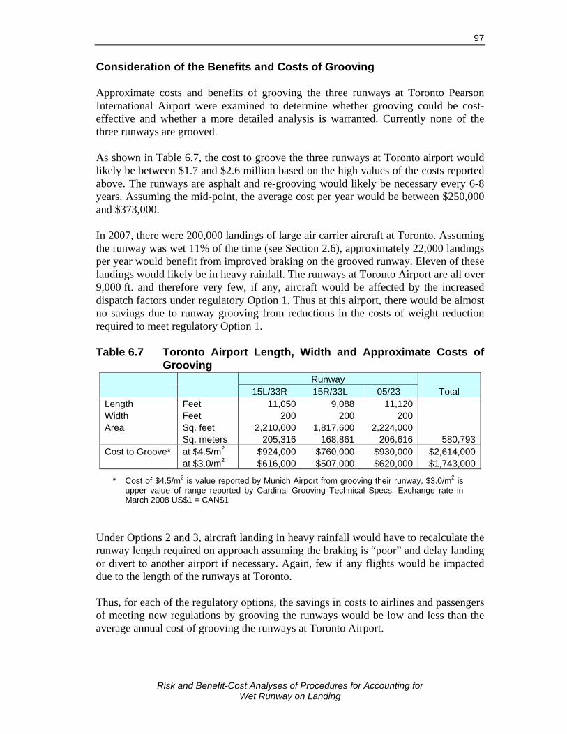
Risk and Benefit-Cost Analyses of Procedures for Accounting for
Wet Runway on Landing
97
Consideration of the Benefits and Costs of Grooving Approximate costs and benefits of grooving the three runways at Toronto Pearson International Airport were examined to determine whether grooving could be cost-effective and whether a more detailed analysis is warranted. Currently none of the three runways are grooved. As shown in Table 6.7, the cost to groove the three runways at Toronto airport would likely be between $1.7 and $2.6 million based on the high values of the costs reported above. The runways are asphalt and re-grooving would likely be necessary every 6-8 years. Assuming the mid-point, the average cost per year would be between $250,000 and $373,000. In 2007, there were 200,000 landings of large air carrier aircraft at Toronto. Assuming the runway was wet 11% of the time (see Section 2.6), approximately 22,000 landings per year would benefit from improved braking on the grooved runway. Eleven of these landings would likely be in heavy rainfall. The runways at Toronto Airport are all over 9,000 ft. and therefore very few, if any, aircraft would be affected by the increased dispatch factors under regulatory Option 1. Thus at this airport, there would be almost no savings due to runway grooving from reductions in the costs of weight reduction required to meet regulatory Option 1. Table 6.7 Toronto Airport Length, Width and Approximate Costs of
Grooving
* Cost of $4.5/m2 is value reported by Munich Airport from grooving their runway, $3.0/m2 is
upper value of range reported by Cardinal Grooving Technical Specs. Exchange rate in March 2008 US$1 = CAN$1
Under Options 2 and 3, aircraft landing in heavy rainfall would have to recalculate the runway length required on approach assuming the braking is “poor” and delay landing or divert to another airport if necessary. Again, few if any flights would be impacted due to the length of the runways at Toronto. Thus, for each of the regulatory options, the savings in costs to airlines and passengers of meeting new regulations by grooving the runways would be low and less than the average annual cost of grooving the runways at Toronto Airport.
Runway 15L/33R 15R/33L 05/23 Total
Length Feet 11,050 9,088 11,120 Width Feet 200 200 200 Area Sq. feet 2,210,000 1,817,600 2,224,000 Sq. meters 205,316 168,861 206,616 580,793Cost to Groove* at $4.5/m2 $924,000 $760,000 $930,000 $2,614,000 at $3.0/m2 $616,000 $507,000 $620,000 $1,743,000
Risk and Benefit-Cost Analyses of Procedures for Accounting for
Wet Runway on Landing
98
The benefits of grooving were also considered from the perspective of reduced overrun costs, rather than reduced cost of meeting alternate regulations. With the long runway distance available at Toronto, almost all of the benefits due to reduction in overruns will be attributable to large wide-body aircraft (e.g., A340, B777, B747). The overrun rate for these aircraft landing on a 9,088 ft. wet un-grooved runway is estimated to be approximately 1 per million landings. There were approximately 1,000 landing of these aircraft on wet runways at Toronto in 2007 and the expect total overrun cost for these 1,000 landings is estimated to range from $65,000 for the 9,088 ft. runway (with 200 ft. to ditch/ravine) to only $200 for the 11,100 ft. runway. Overrun costs if the runways were grooved were negligible. Most of these accident costs are attributable to overrunning the runway during heavy rainfall. For operational reasons these aircraft are sometimes directed to land on the shorter runway,38 even during moderate to heavy rainfall and there would therefore be a significant benefit of the runway being grooved. The cost of overruns of smaller aircraft types would increase this a little, likely by about 10%. Thus, the savings in accidents costs would likely be less than the average annual cost of grooving the runways at Toronto Airport. Note that grooving of the runway will also reduce the overrun costs associated with abort take-offs on wet runways and these have not been considered here. The benefits and costs will vary by airport and by type of runway surface. Average annual costs for grooving runways are much less on concrete runways as the frequency of re-grooving is reduced substantially and may bring the costs of grooving down to levels comparable to, or less than, the benefit of reduced overrun costs. 6.5 Summary The risk analysis found that the risks associated with landing on wet un-grooved runways are much higher than landing on a dry runway or a wet grooved runway. The benefit-cost analysis indicates that it is not easy to mitigate these higher risks in a cost beneficial manner. Increasing the dispatch factor when the arrival runway is expected to be wet for un-grooved/non-PFC runways incurs a relatively small penalty but the penalty applies to many flights, and does not target the flights most at risk. With the increased dispatch factors for all wet runway condition when the runway is un-grooved, total costs are high and greatly exceed the benefits of reduced accident benefits for most aircraft. This was found to be the cases both for aircraft with and aircraft without reverse thrust. Only for very large turboprop aircraft was the increased dispatch factor found to be cost-beneficial. Requiring pilots to recalculate the landing distance just prior to landing assuming braking will be “poor” when rainfall is heavy and the runway is un-grooved targets landings at greatest risk. However, if the re-calculated landing distance is greater than 38 As was the case for the A340 Air France accident at Toronto in 2006.

Risk and Benefit-Cost Analyses of Procedures for Accounting for
Wet Runway on Landing
99
the runway available, the options of delaying landing or diverting to another airport are expensive and total costs are substantial. The benefits of reduced overrun costs are close to, or greater, than costs when the en route check requirement is made with the current dispatch factor requirements. Thus, this approach is cost-beneficial, but the requirement does not reduce the risk for landings in less wet conditions and the overrun rate is still much higher than on dry or grooved runways. When the en route check requirement is applied with the increased dispatch factors, the benefit-cost ratios are similar to those with just the increased dispatch factors and costs far exceed the benefits for most aircraft. The cost-effectiveness of the requirement to increase dispatch factors could be improved if it is only required when the weather forecast is for moderate or heavy rainfall at the time of arrival at the destination. These rainfall conditions typically occur less than 5% of the time (3.3% estimated for Canada). Requiring the increased wet runway dispatch factor only when moderate or heavy rainfall is forecast could increase the benefit-cost ratio by a factor of eight, provided the forecasts are accurate. The benefit-cost ratio would range from 0.3 to 13 and the ratio being greater than one for five of the eight aircraft examined. The requirement would, of course, require forecasts of rainfall rates and these may not provide accurate forecasts of rainfall rates at particular times. The requirement to make an en route landing distance calculation assuming braking is “poor” if rainfall is heavy would reduce the risks in situations where the forecasts were inaccurate and rainfall is heavier than expected. Also, by not increasing dispatch factors for most landings, airlines which currently include the 15% wet runway dispatch factor for all operations would likely continue this practice, thus not reducing this additional safety margin available for dry runway conditions. Grooving of the runway will greatly reduce the risks of landing on wet runways, particularly during heavy rainfall. Experience in the US and at Munich Airport indicates that grooving does not present any significant problems in cold winter (snow) conditions. The brief analysis of costs and benefits of grooving runways at a large international airport indicates that few flights would be affected by the increased dispatch factor or en route check requirements considered and thus the costs of grooving would be much greater than savings to airlines and passengers of meeting those requirements. The benefits of reduced accidents were estimated to be less than the cost of grooving the runways, but this will vary depending on the runway length, types and weights of aircraft and the runway safety areas at the airport. Where grooving has a long life-span (e.g., on concrete runways), annual costs are reduced and benefits are more likely to exceed costs.

Risk and Benefit-Cost Analyses of Procedures for Accounting for
Wet Runway on Landing
100
Risk and Benefit-Cost Analyses of Procedures for Accounting for
Wet Runway on Landing
101
7. FINDINGS AND RECOMMENDED OPTIONS
7.1 Findings Accident/Incident Analysis
The risk of a jet or large turboprop aircraft overrunning the end of the runway on landing when the runway is wet varies by country/region and has declined over the past 30 years. Worldwide, the risk of an overrun accident when landing on a wet runway is approximately seven times greater than when the runway is dry based on accidents during the period 1990-2007.
The risks of overrun accidents when landing on wet runways are much lower in countries or regions where runways are grooved. The ratio of the risk of an overrun accident on a wet runway compared to the risks on a dry runway were estimated to be approximately: • 10 on un-grooved/non-PFC runways • 2.5 on grooved/PFC runways Grooved or PFC runways reduced the risks of an accident on a wet runway by approximately 75%.
The risks of landing overruns on wet runways for aircraft without reverse thrust are approximately six times greater than for aircraft with reverse thrust.
The overrun accident rate on wet runways in Canada is six times the rate for the US. The rate for other countries is three times the US rate.
Overrun landing accidents are much more likely during heavy rainfall, especially on un-grooved runways.
Heavy rainfall is very often associated with other conditions such as strong and gusty winds, wind shear and poor visibility, which by themselves are common factors associated with overrun accidents. This makes heavy rainfall an especially hazardous condition.
Wet Runway Condition Frequency and Reporting
Runways conditions are wet approximately 10% to 15% of the time in Canada and Europe.
Approximately 3-4% of the time rain is falling, the rainfall rate is heavy (i.e., one minute rates equivalent to or greater than 10 mm or 0.4 in. per hour).
Water depths on runways are often greater than 3 mm during heavy rainfall.
Reporting of the runway condition during heavy rainfall is often inadequate. The risk due to misreporting of runway condition as wet instead of flooded is compounded for aircraft landing on un-grooved runways.

Risk and Benefit-Cost Analyses of Procedures for Accounting for
Wet Runway on Landing
102
The current terminology used to describe the runway condition during heavy rainfall does not adequately reflect the risks of landing, as the risks on an un-grooved flooded runway can be very much greater than on a grooved wet runway.
Runways are either grooved or have PFC overlay at almost all airports with commercial jet service in the US, UK, Australia and Japan, at most major airports in continental Europe, and at many of the major airports in other countries. Only two airports in Canada, both small regional airports, have grooved or PFC runways.
Aircraft Performance Analysis
Stopping/braking distances on wet runways are significantly lower for landings on runways with high texture, grooved or PFC overlay surfaces. The increase in stopping/braking distance (different from landing distance, which also includes the distance in the air from 50 ft. above runway to the touchdown point and the transition distance before full braking is achieved) on a wet runway, relative to dry conditions, is usually around: • 15% for a well-maintained, grooved or PFC runway • 100% for a runway without grooving or PFC
Use of reverse thrust has a minor effect on the landing distance on a dry runway, but significantly reduces the landing distance on wet runways. The reduction is approximately: • 11% on un-grooved/non-PFC runways • 6% on grooved/PFC runways
The risk of dynamic or partial hydroplaning when landing during heavy rainfall is much greater on un-grooved runways.
The results from the Falcon 20 tests at North Bay by NRC indicate that to maintain the same safety margin on a wet runway as a dry runway, the dispatch factor should be increased above the current level of 1.92. However, the tests were conducted on an un-grooved runway and the aircraft did not have reverse thrust capability. If the stopping distance is adjusted to account for the typical reductions in stopping distance due to runway grooving and use of reverse thrust, the wet runway dispatch factor of 1.92 was found to be appropriate.
Monte Carlo tests conducted by Transport Canada using the method for calculating the aircraft braking coefficient specified in FAR 25.109 found that the current landing distance adjustment factors for both jet and turboprop aircraft with reverse thrust (or discing) are adequate on typical grooved runways, but are too low for landings on typical un-grooved runways.
The current wet runway adjustment factors of 1.92 for jet aircraft and 1.64 for large turboprop aircraft are adequate for landing on a runway with a well-maintained, highly textured, grooved or PFC overlay surface for aircraft with reverse thrust or discing capability.
Higher wet runway adjustment factors are required to maintain the same margin of safety as on dry runways for:

Risk and Benefit-Cost Analyses of Procedures for Accounting for
Wet Runway on Landing
103
• Jet aircraft without reverse thrust and turboprop aircraft without discing capability, and/or
• Landings on wet runways without a well-maintained, highly textured, grooved or PFC overlay surface.
The FAA and JAA distinguish between runways with grooved or PFC surfaces and those without grooved or PFC surfaces when specifying performance criteria for accelerate-stop on take-off, but currently do not account for runway surface type in performance criteria for landing.
Acceptable Costs for Reducing a Fatality
The acceptable level of cost for reducing a fatality in a transportation accident was found to vary between countries from $2 to $4 million. The value used in the US is $3 million and in the UK, £1,428,180 (C$3.3 million). A similar rate has been used in recent aviation benefit-cost studies in Canada.
Current Risks of Landing on Wet Runways
Most landings on wet runways (95-97%) occur when there is no or only light rainfall. The risks for these landings under current regulations on an un-grooved runway are approximately four times greater than landing on a dry runway. Risks for landing on a grooved runway during light rainfall are marginally greater than on a dry runway.
Risks are very high for landing during heavy rainfall on un-grooved runways and well beyond acceptable risks in aviation.
Risks are high for landing on grooved runways during very heavy rainfall and are greater than acceptable risks in aviation.
Risks Under Alternate Wet Runways Requirements
Increasing the wet runway dispatch factors as given under regulatory Option 1 for aircraft with reverse thrust reduces the risks of landing on wet un-grooved runways to a little above those for landing on dry runways, and slightly less than those for landing on wet grooved runways.
The dispatch factor of 2.45 under Option 1 for aircraft without reverse thrust landing on an un-grooved runway reduces the risks to below those for a dry runway. A factor of 2.25 gives risks comparable with those on a dry runway.
The requirement to do an en route landing distance calculation in addition to the increased dispatch factors as described under Option 2 greatly reduces the risks when landing on an un-grooved runway under heavy rainfall conditions and, overall, results in a significant reduction in the risks. Note that under Option 2, the adjustment factor for these rainfall conditions is applicable for “poor” braking
Option 1: Wet Runway Grooved Landing Distance or PFC Other Dispatch Factor Runways Runways Jet without reverse thrust 2.00 2.45 Jet with reverse thrust 1.92 2.10 Turbo-propeller aircraft 1.64 1.90
Risk and Benefit-Cost Analyses of Procedures for Accounting for
Wet Runway on Landing
104
and is typically well below that given by the manufacturer’s adjustment for landing on runways with 3 to 6 mm of water.
The en route calculation as described under Option 2 for landing on a grooved runway typically has no effect on the risks for many aircraft as the adjustment factor based on manufacturer’s material for landing on runways with 3 to 6 mm of water is usually below the current wet runway adjustment factor.
Use of the en route requirement with current wet runway dispatch factors (1.92 for jet and 1.64 for turboprop aircraft), Option 3, reduces the risk from the current regulations significantly, but risks are still much greater than for a dry runway and greater than under Option 1.
Benefit-Cost Ratios of Alternate Wet Runway Requirements
Increasing the dispatch factor on un-grooved runways and for aircraft without reverse thrust when the arrival runway is expected to be wet as outlined in Option 1 incurs a relatively small penalty on many flights, and does not target the flights most at risk. When Option 1 is applied to all wet runway landings, total costs are high and greatly exceed the benefits of reduced accidents for most aircraft.
Requiring pilots to recalculate the landing distance just prior to landing assuming braking will be “poor” when rainfall is heavy and the runway is un-grooved targets landings at greatest risk. Benefit-cost ratios are close to, or greater than, one when the en route check requirement is made with the current dispatch factor requirements. This approach is cost-beneficial, but the requirement does not reduce the risk for landings in less wet conditions and the overrun rate is still much higher than on dry or grooved runways.
When the en route check requirement is applied with the increased dispatch factors, Option 2, for all wet runway landings, costs far exceed the benefits for most aircraft.
The requirement to increase dispatch factors only when the weather forecast is for moderate or heavy rainfall at the time of arrival at the destination improves the benefit-cost ratio by a factor of eight, provided the forecasts are accurate. Benefit-cost ratios would be greater than one for the majority of aircraft landings. The requirement to make an en route landing distance calculation assuming braking is “poor” if rainfall is heavy would reduce the risks in situations where the forecasts were inaccurate and rainfall is heavier than expected.
Costs for off-loading passengers are five to six times higher than for off-loading cargo and if weight reductions must be met by off-loading passengers, the costs will far exceed the benefits of increasing the dispatch factors.
The brief analysis of costs and benefits of grooving runways at a large international airport indicates that few flights would be affected by the increased dispatch factor or en route landing distance calculation requirements considered. The costs of grooving would be much greater than savings to airlines and passengers of meeting those requirements. The benefits of reduced accidents will
Risk and Benefit-Cost Analyses of Procedures for Accounting for
Wet Runway on Landing
105
vary depending on the runway length and surface type, types and weights of aircraft and the runway safety areas at the airport. The benefits may exceed the costs of runway grooving at some airports, particularly where the grooving has a long lifespan, the runway safety area is small and/or a high proportion of aircraft landings are at or close to being weight restricted.
7.2 Recommendations The following recommendations are made:
1) The following requirements for landing on wet runways should be examined by ICAO with a view to worldwide implementation of the requirement:
At the commencement of final approach, if:
a) The runway is un-grooved and the depth of water on the runway is greater than 3 mm or if rainfall at the airport is reported as heavy, the required landing distance must be recalculated assuming the runway is flooded (i.e., water depth greater than 3 mm) and the braking is “poor” using manufacturer’s guidance material, or
b) The runway is grooved or PFC and the depth of water on the runway is greater than 3 mm or if rainfall at the airport is reported as very heavy, the required landing distance must be recalculated assuming the runway is flooded using manufacturer’s guidance material.
If the calculated distance is less than the runway length available, the pilot must not attempt to land, except in emergency situations.
2) The reporting and forecasts of rainfall rates should be examined with a view to implementing the following dispatch requirement:
a) If the runway at the destination airport is forecast to be wet at the time of arrival with either light rainfall or no rainfall occurring, use the current dispatch factors: • Jet aircraft 1.92 • Turbopropeller aircraft 1.64 for both grooved/PFC and un-grooved/non-PFC runways.
b) For forecasts of moderate or heavy rainfall at the time of arrival at the destination airport, use the following dispatch factors, dependent on runway surface type:

Risk and Benefit-Cost Analyses of Procedures for Accounting for
Wet Runway on Landing
106
Grooved or Other PFC Runways Runways • Jet without reverse thrust 2.00 2.2539 • Jet with reverse thrust 1.92 2.10 • Turbopropeller aircraft 1.64 1.90
If an internationally acceptable method can be found for reliably measuring runway texture that correlates well with aircraft braking efficiency on a wet runway, the above requirement for grooved runways could be extended to very highly textured un-grooved (ESDU Category D or E) runways.
The examination of reporting and forecasts of rainfall rates would include the consistency of terms, accuracy of forecasts, feasibility of providing qualitative rainfall rates to the pilot both en route and prior to take-off, and the frequency of occurrence of different rainfall rates.
3) ICAO should develop guidance material to provide pilots with the necessary knowledge, skills and procedures for making the decision on whether to land and for conducting a safe landing during heavy rainfall conditions, particularly if the runway does not have a grooved or PFC surface.
4) Guidance material provided by manufacturers for calculating landing distances on wet and flooded runways should distinguish between runways that are grooved or have PFC overlay and un-grooved/non-PFC runways.
The following future work is recommended:
1) Conduct an analysis of the impacts on air carriers and the benefits and costs of the en route and dispatch requirements specified in recommendations 1) and 2) for a range of countries to provide additional information for supporting implementation of the requirements.
2) Examine the benefits and costs of grooving or installing PFC surface on runways at major airports in Canada, particularly at airports with high rainfall, where a significant number of commercial operations have landing field lengths equal or close to the runway length available and/or have hazards in the runway overrun areas.
3) Develop mechanisms for determining the water depth on the runway during heavy rainfall and provide pilots with runway condition reports that distinguish between wet and flooded runways. The water depth, when flooded, should also be provided, including during transient periods of heavy rainfall. In the absence of such data, pilots should assume that the runway is flooded during periods of heavy rainfall, particularly for runways without grooved or PFC surfaces.
39 Croll recommended a value of 2.45 based on flight tests with a Falcon 20 [24], but the benefit-cost
analysis using a CRJ indicated a value of 2.25 was appropriate.

Risk and Benefit-Cost Analyses of Procedures for Accounting for
Wet Runway on Landing
107
REFERENCES
[1] Transport Canada, NPA 2003-130, Definitions Applicable to Contaminated Runway Surfaces, May 2003.
[2] Flight Safety Foundation, Approach and Landing Accident Reduction Tool Kit: Wet or Contaminated Runways, November 2000, pp. 179-183.
[3] Federal Aviation Administration, Landing Performance Assessments at the Time of Arrival (Turbojets), Safety Alert to Operators (SAFO) No. 06012, 31 August 2006.
[4] Biggs, D.C., and Hamilton, G.B. (Sypher:Mueller International), Runway Friction Accountability Risk Assessment – Results of a Survey of Canadian Airline Pilots, TP 13941E, Transportation Development Centre, Transport Canada, June 2002.
[5] Transport Canada, Aircraft Movement Surface Condition Reporting (AMSCR) for Winter Operations, Aerodrome Safety Circular 2000-002, Aerodrome Safety Branch, Civil Aviation Directorate, September 2000.
[6] Horne, W., Elements Affecting Runway Traction, Presented at the SEA Transport Committee Meeting, Dallas, April 30-May 2, 1974.
[7] Horne, W., Wet Runways, NASA Technical Memorandum TM X-72650, 1975. [8] Comfort, G. (Fleet Technology Ltd.), Wet Runway Friction: Literature and
Information Review, TP 14002E, Transportation Development Centre, Transport Canada, August 2001.
[9] Yager, T., Factors Influencing Aircraft Ground Handling Performance, NASA Technical Memorandum 85652, 1983, p. 20.
[10] Federal Aviation Administration, Runway Safety Area Improvements in the United States, Fourteenth Meeting of the CAR/SAM Regional Planning and Implementation Group (GREPECAS/14), International Civil Aviation Organization, San Jose, Costa Rica, 16-20 April 2007.
[11] Transportation Safety Board of Canada, Toronto Air France Accident, Aviation Investigation Update TSB Investigation Number A05H0002, 16 November 2005.
[12] Biggs, D.C., Hamilton, G.B., Owen, K.D.J., McLeish, W., and Reid, L.D. (Sypher:Mueller International), Aircraft Take-off Performance and Risks for Wet and Contaminated Runways in Canada, TP 10888E, Transportation Development Centre, Transport Canada, July 1991.
[13] Lee, J.H., Choi, Y.S., Pack, J.K., and Ha, E.H., Conversion of Rain Rate Distribution for Various Integration Time, International Union of Radio, 2005 General Assembly Proceedings, p. 1450.
[14] Singh, M., Singh, J., Tankaka, K., and Mitsuyosh, I., Conversion of 60-, 30- 10-, and 5-Minute Rain Rates to 1-Minute Rates in Tropical Rain Rate Measurement, ETRI Journal, Vol. 29, No. 4, August 2007.
Risk and Benefit-Cost Analyses of Procedures for Accounting for
Wet Runway on Landing
108
[15] van Es, G.W.H., Roelen, A.L.C., Kruijsen, E.A.C., and Giesberts, M.K.H., Safety Aspects of Aircraft Performance on Wet and Contaminated Runways, National Aerospace Laboratory, report no. NLR-TP-2001-216, May 2001.
[16] Yager T.J., Phillips, W.P., Horne, W.B., and Sparks, H.C., A comparison of aircraft and ground vehicle stopping performance on dry, wet, flooded, slush, snow and ice covered runways. NASA TN D-6098, November 1970.
[17] Yager, T.J., Vogler, W.A., and Baldasare, P., Evaluation of Two Transport Aircraft and Several Ground Test Vehicle Friction Measurements Obtained for Various Runway Surface Types and Conditions – A Summary of Test Results from Joint FAA/NASA Runway Friction Program, NASA Technical Paper 2917, February 1990.
[18] Federal Aviation Administration, Measurement, Construction, and Maintenance of Skid-Resistant Airport Pavement Surfaces, Advisory Circular (AC) 150/5320-12(C), 18 March 1997.
[19] Federal Aviation Administration, Chapter 3 Airplane Performance and Airport Data, Paragraph 921, FAA 8400.10CHG 5, Water and Contamination of Runway, 30 June 1991.
[20] Giesman, Paul, Wet Runway, Physics, Certification, Application, Boeing, 2005.
[21] Hamilton, G.B., Biggs, D.C., and Owen, K.D.J. (Sypher:Mueller International), Aeroplane Take-off and Landing Performance from Contaminated Runways, TP 12596E, Transportation Development Centre, Transport Canada, November 1995.
[22] ESDU, Frictional and Retarding Forces on Aircraft Tyres, ESDU Item No. 71026, Updated 1981.
[23] Croll, J., and Bastian, M., Falcon 20 Aircraft Braking Performance on Wet Concrete Runway Surfaces, TP 14273E, Transportation Development Centre, Transport Canada, Report LTR-FR-207, Institute for Aerospace Research, National Research Council Canada, July 2004.
[24] Croll, J., and Bastian, M., Evaluation of Falcon 20 Turbojet and DHC-8 Series 100 and 400 Turbopropeller Aircraft Safety Margins for Landings on Wet Runway Surfaces, TP 14627E, Transportation Development Centre, Transport Canada, Report LTR-FR-251, Institute for Aerospace Research, National Research Council Canada, September 2006.
[25] Martin, J.C.T., Results of a Monte Carlo Statistical Analysis of Operational Landing Distances on Dry and Wet Runways for Turbopropeller Powered Aircraft, Transport Canada Aircraft Certification Flight Test Division Discussion Paper No. 29, October 2003.
[26] Martin, J.C.T., Results of a Monte Carlo Statistical Analysis of Operational Landing Distances on Dry and Wet Runways for Turbojet Powered Aircraft, Transport Canada Aircraft Certification Flight Test Division Discussion Paper No. 22, December 2001.

Risk and Benefit-Cost Analyses of Procedures for Accounting for
Wet Runway on Landing
109
[27] Martin, J.C.T., Results of a Monte Carlo Statistical Analysis of Operational Landing Distance Factors on Wet High Friction Runways for Turbojet Powered Aircraft, TC Aircraft Certification Flight Test Division Discussion Paper No. 24, March 2007.
[28] van Es, G.W.H., Running out of runway – Analysis of 35 years of landing overrun accidents, Report NLR-TPO-2005-498, National Aerospace Laboratory, August 2005.
[29] Biggs, D.C., Hamilton, G.B., and Owen, K.D.J. (Sypher:Mueller International), Benefit-Cost Analysis of Procedures for Accounting for Runway Friction on Landing, TP 14082E, Transportation Development Centre, Transport Canada, March 2003.
[30] Flight Safety Foundation, Flight Safety Digest, August-November 2000.
[31] Flight Safety Foundation, Business Jet Operations, Flight Safety Digest, May 2004.
[32] Australian Transport Safety Bureau, Boeing 747-438, VH-OJH Bangkok, Thailand, Investigation Report 199904538, 23 September 1999.
[33] Kirkland, I.D.L, and Caves, R.E., A New Aircraft Overrun Database 1980-1998, Department of Civil Engineering, Loughborough University, Leicestershire, UK, 2001.
[34] Ranganathan, Captain A., Wet Runway Overruns: Pilot Error? System Deficiency?, ISASI Forum, January-March 2006.
[35] Biggs, D.C., Hamilton, G.B., Owen, K.D.J., McLeish, W., and Black, F. (Sypher:Mueller International), Aircraft Take-off Performance and Risks for Wet and Contaminated Runways in Canada, TP 11966E, Transportation Development Centre, Transport Canada, May 1994.
[36] Croll, J.B., Martin, J.C.T., and Bastian, M., Falcon 20 Aircraft Performance Testing on Contaminated Runway Surfaces During the Winter of 1998/1999, TP 13557E, Transportation Development Centre, Transport Canada, Report LTR-FR-158, Institute for Aerospace Research, National Research Council Canada, December 1999.
[37] Skillen, G.J.R., Risk – Worked Example on Landing Distance, ESDU Restricted Circulation Paper P571H, Draft copy, November 2007.
[38] Sypher:Mueller International, The Development of Operational Airworthiness Requirements, prepared for Transport Canada, December 1991.
[39] Monroe, R.L., McLeish, W.M., and Biggs, D. (Sypher:Mueller International), Regulatory and Economic Impact of Mandatory Requirements for Shoulder Harnesses in Small Commercial Aeroplanes and Commercial Helicopters, TP 10525E, Transportation Development Centre, Transport Canada, May 1990.
[40] GRA Incorporated, Economic Values for FAA Investment and Regulatory Decisions, A Guide (the Economic Values Report), GRA Incorporated, 29 December 2004.

Risk and Benefit-Cost Analyses of Procedures for Accounting for
Wet Runway on Landing
110
[41] Directorate of Airspace Policy, Proposal to Amend the Air Navigation Order 2000 to Require the Carriage of Airborne Collision Avoidance System II, Civil Aviation Authority, London, UK, November 2004.
[42] UK Department of Transport, 2005 Valuation of the Benefits of Prevention of Road Accidents and Casualties, Highways Economic Note No. 1, January 2007.
[43] Bureau of Transport Economics, Road Crash Costs in Australia, Report No. 102, May 2000.
[44] Civil Aviation Safety Authority, Flight Safety Australia Magazine, Vol 10 No 2, March-April 2006.
[45] NAV CANADA, Assessment of Aerodrome Forecast (TAF) Accuracy Improvement, May 2002.
[46] Agrawal, S.K., and Daiutolo, H., The Braking Performance of an Aircraft Tire on Grooved Portland Cement Concrete Surfaces, FAA-RD-80-78, January 1981.
[47] Agrawal, S.K., Braking of an Aircraft Tire on Grooved and Porous Asphaltic Concrete, DOT/FAA-RD-82-77, January 1983.
[48] Cardinal Grooving Technical Specs: http://www.cardinalgrooving.com/technicalspecs.html
[49] Niedermeire, S., To Groove or Not to Groove – that is the Question. Presentation to Swift Conference, September 2006.
[50] Federal Aviation Administration, Airport Winter Safety and Operations, Advisory Circular 150/5200-30B, dated 9/5/2007, paragraph 4.7A(1).
[51] American Concrete Pavement Association, Concrete Pavement Successes, Pamphlet produced by the American Concrete Pavement Association, Skokie, Illinois, 2000.
Risk and Benefit-Cost Analyses of Procedures for Accounting for
Wet Runway on Landing
Appendix A
Sections of Canadian Aviation Regulations for Commercial Air Services on Landing Distance Requirements

Appendix A Risk and Benefit-Cost Analyses of Procedures for Accounting for
Wet Runway on Landing
A-1
CAR Standards Sections Relevant to Landing Distance Requirements Part V - Airworthiness Chapter 525 - Transport Category Aeroplanes
525.125 Landing (a) The horizontal distance necessary to land and to come to a complete stop (or to a speed of approximately 3 knots of water landings) from a point 50 ft. above the landing surface must be determined (for standard temperatures, at each weight, altitude and wind within the operational limits established by the applicant for the aeroplane) as follows: (1) The aeroplane must be in the landing configuration.
(2) A stabilised approach, with a calibrated airspeed of not less than 1.3 VS or VMCL, whichever is greater, must be maintained down to the 50 foot height.
(3) Changes in configuration, power or thrust, and speed, must be made in accordance with the established procedures for service operation.
(4) The landing must be made without excessive vertical acceleration, tendency to bounce, nose over, ground loop, porpoise, or water loop.
(5) The landing may not require exceptional piloting skill or alertness. (b) [For landplanes and amphibians, the landing distance on land must be determined on a level, smooth, dry, hard-surfaced runway. In addition:] (1) The pressures on the wheel braking systems may not exceed those specified by the brake manufacturer;
(2) The brakes may not be used so as to cause excessive wear of brakes or tires; and
(3) Means other than wheel brakes may be used if that means: (i) Is safe and reliable; (ii) Is used so that consistent results can be expected in service; and (iii) Is such that exceptional skill is not required to control the aeroplane. (c) For seaplanes and amphibians, the landing distance on water must be determined on smooth water.
(d) For skiplanes, the landing distance on snow must be determined on smooth, dry snow.
(e) The landing distance data must include correction factors for not more than 50 percent of the nominal wind components along the landing path opposite to the direction of landing, and not less than 150 percent of the nominal wind components along the landing path in the direction of landing.
Appendix A Risk and Benefit-Cost Analyses of Procedures for Accounting for
Wet Runway on Landing
A-2
(f) If any device is used that depends on the operation of any engine, and if the landing distance would be noticeably increased when landing is made with that engine inoperative, the landing distance must be determined with that engine inoperative unless the use of compensating means will result in a landing distance not more than that with each engine operating. __________________________
Aeroplane Flight Manual
525.1581 General (g) The Aeroplane Flight Manual shall contain information in the form of approved guidance material for supplementary operating procedures and performance information for operating on contaminated runways.] __________________________ Part VII - Commercial Air Services
Dispatch Limitations: Landing at Destination and Alternate Aerodromes
705.60 (1) Subject to subsection (3), no person shall dispatch or conduct a take-off in an aeroplane unless
(a) the weight of the aeroplane on landing at the destination aerodrome will allow a full-stop landing
(i) in the case of a turbo-jet-powered aeroplane, within 60 per cent of the landing distance available (LDA), or
(ii) in the case of a propeller-driven aeroplane, within 70 per cent of the landing distance available (LDA); and
(b) the weight of the aeroplane on landing at the alternate aerodrome will allow a full-stop landing
(i) in the case of a turbo-jet-powered aeroplane, within 60 per cent of the landing distance available (LDA), and
(ii) in the case of a propeller-driven aeroplane, within 70 per cent of the landing distance available (LDA).
Appendix A Risk and Benefit-Cost Analyses of Procedures for Accounting for
Wet Runway on Landing
A-3
(2) In determining whether an aeroplane can be dispatched or a take-off can be conducted in accordance with subsection (1), the following shall be taken into account:
(a) the pressure-altitude at the destination aerodrome and at the alternate aerodrome;
(b) not more than 50 per cent of the reported headwind component or not less than 150 per cent of the reported tailwind component; and
(c) that the aeroplane must be landed on a suitable runway, considering the wind speed and direction, the ground handling characteristics of the aeroplane, and other conditions such as landing aids and terrain.
(3) Where conditions at the destination aerodrome at the time of take-off do not permit compliance with paragraph (2)(c), an aeroplane may be dispatched and a take-off conducted if the alternate aerodrome designated in the operational flight plan permits, at the time of take-off, compliance with paragraph (1)(b) and subsection (2).
Dispatch Limitations: Wet Runway - Turbo-jet-powered Aeroplanes 705.61 (1) Subject to subsection (2), when weather reports or forecasts indicate that the runway may be wet at the estimated time of arrival, no air operator shall dispatch or conduct a take-off in a turbo-jet-powered aeroplane unless the landing distance available (LDA) at the destination aerodrome is at least 115 per cent of the landing distance required pursuant to paragraph 705.60(1)(a).
(2) The landing distance available on a wet runway may be shorter than that required by subsection (1), but not shorter than that required by Section 705.60, if the aircraft flight manual includes specific information about landing distances on wet runways.

Risk and Benefit-Cost Analyses of Procedures for Accounting for
Wet Runway on Landing
Appendix B
Estimation of Wet Runway Factor for Falcon 20 on a Grooved Runway

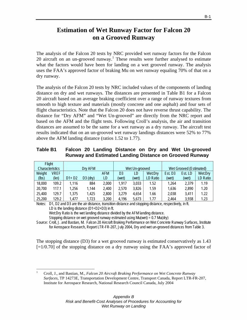
Appendix B
Risk and Benefit-Cost Analyses of Procedures for Accounting for Wet Runway on Landing
B-1
Estimation of Wet Runway Factor for Falcon 20 on a Grooved Runway
The analysis of the Falcon 20 tests by NRC provided wet runway factors for the Falcon 20 aircraft on an un-grooved runway.1 These results were further analysed to estimate what the factors would have been for landing on a wet grooved runway. The analysis uses the FAA’s approved factor of braking Mu on wet runway equaling 70% of that on a dry runway. The analysis of the Falcon 20 tests by NRC included values of the components of landing distance on dry and wet runways. The distances are presented in Table B1 for a Falcon 20 aircraft based on an average braking coefficient over a range of runway textures from smooth to high texture and materials (mostly concrete and one asphalt) and four sets of flight characteristics. Note that the Falcon 20 does not have reverse thrust capability. The distance for “Dry AFM” and “Wet Un-grooved” are directly from the NRC report and based on the AFM and the flight tests. Following Croll’s analysis, the air and transition distances are assumed to be the same for a wet runway as a dry runway. The aircraft test results indicated that on an un-grooved wet runway landings distances were 52% to 77% above the AFM landing distance (ratios 1.52 to 1.77). Table B1 Falcon 20 Landing Distance on Dry and Wet Un-grooved
Runway and Estimated Landing Distance on Grooved Runway
Flight Characteristics Dry AFM Wet Un-grooved Wet Grooved (Estimated)
Weight (lbs)
VREF (kn) D1+ D2 D3 (dry)
AFM LD
D3 (wet)
LD (wet)
Wet:Dry LD Ratio
Est. D3 (wet)
Est. LD (wet)
Wet:Dry LD Ratio
18,000 109.2 1,116 884 2,000 1,917 3,033 1.52 1,264 2,379 1.19 20,700 117.1 1,256 1,144 2,400 2,570 3,826 1.59 1,636 2,890 1.20 25,400 129.7 1,375 1,425 2,800 3,279 4,654 1.66 2,038 3,411 1.22 25,200 129.2 1,477 1,723 3,200 4,196 5,673 1.77 2,464 3,938 1.23 Notes: D1, D2 and D3 are the air distance, transition distance and stopping distance, respectively, in ft. LD is the landing distance (D1+D2+D3) in ft. Wet:Dry Ratio is the wet landing distance divided by the AFM landing distance. Stopping distance on wet grooved runway estimated using Mu(wet) = 0.7 Mu(dry) Source: Croll, J. and Bastian, M. Falcon 20 Aircraft Braking Performance on Wet Concrete Runway Surfaces, Institute
for Aerospace Research, Report LTR-FR-207, July 2004, Dry and wet un-grooved distances from Table 3.
The stopping distance (D3) for a wet grooved runway is estimated conservatively as 1.43 [=1/0.70] of the stopping distance on a dry runway using the FAA’s approved factor of
1 Croll, J., and Bastian, M., Falcon 20 Aircraft Braking Performance on Wet Concrete Runway
Surfaces, TP 14273E, Transportation Development Centre, Transport Canada, Report LTR-FR-207, Institute for Aerospace Research, National Research Council Canada, July 2004

Appendix B
Risk and Benefit-Cost Analyses of Procedures for Accounting for Wet Runway on Landing
B-2
braking Mu on wet runway equaling 70% of that on a dry runway.2 Using this estimate, the landing distance on a wet grooved runway is 19% to 23% greater than the AFM landing distance (ratios 1.19 to 1.23). The effect of the grooved runway is to reduce the landing distance by between 22% and 31%, the higher number occurring at the higher aircraft weights and landing speeds. Table B2 gives the factored landing distance on dry, equivalent to the landing field length required, and the excess above the AFM landing distance (calculated by subtraction).3 This excess is the safety margin and is determined from the AFM and factored landing distance (on dry). This excess is added to the landing distance on a wet runway and the total is divided by the AFM landing distance to estimate the factor required to maintain the same safety margin on a wet runway. The factor varies from 2.19 to 2.44 for a wet un-grooved runway, and from 1.86 to 1.90 for a wet grooved runway. This compares with the current factor of 1.92 for wet runways applied at the time of dispatch. Table B2 Wet Runway Landing Distance Factor Based on Falcon 20
Tests for Un-grooved and Grooved Runway
Weight Dry / AFM Wet Un-grooved Wet Grooved (Estimated)
(lb.)
AFM LD (ft.)
Dry Excess
(ft.)
Factored LD (ft.)
LD (wet) (ft.)
LD + Excess
(ft.) Factor
LD (wet) (ft.)
LD + Excess
(ft.) Factor
18,000 2,000 1,340 3,340 3,033 4,373 2.19 2,379 3,719 1.86 20,700 2,400 1,608 4,008 3,826 5,434 2.26 2,890 4,498 1.87 25,400 2,800 1,876 4,676 4,654 6,530 2.33 3,411 5,287 1.89 25,200 3,200 2,144 5,344 5,673 7,817 2.44 3,938 6,082 1.90
Notes: Dry Excess is the safety margin calculated by subtracting the AFM landing distance from the factored landing distance.
Factor is the landing distance plus safety margin (Excess) divided by the AFM landing distance.
2 If the braking force was the only force acting on the aeroplane the stopping distance would increase by
1/0.70. However, as aerodynamic drag forces also act of the aeroplane, and these are not affected by the wet grooved runway, the total braking force will be reduced by less than 30%. Thus use of the 30% of the dry landing distance should result in a conservative distance (i.e., overestimate the distance).
3 Note that distances are from Croll and Bastian and differ slightly from the AFM landing distance / 0.6
due to rounding.
Risk and Benefit-Cost Analyses of Procedures for Accounting for
Wet Runway on Landing
Appendix C
Estimation of Distribution Actual Landing Distance


Appendix C
Risk and Benefit-Cost Analyses of Procedures for Accounting for Wet Runway on Landing
C-1
Estimation of Distribution Actual Landing Distance Approach Used The landing distance is defined as the distance travelled from 50 ft. above the runway until the aircraft comes to a complete stop. The landing distance, LD, is initially estimated based on the LD from the AFM adjusted to account for the effect of the wet runway on aircraft braking. Since the use of reverse thrust is not approved for determining the AFM landing distance for any of the aircraft analyzed, but reverse thrust is used in operational conditions by aircraft with reverse thrust, the AFM landing distance is also adjusted for use of reverse thrust. The AFM landing distance is not representative of landings in typical operations where factors affecting landing distance are less than optimal and significant variation occurs in the landing distances due to a number of factors. In the current analysis, the variability in the point of touchdown, speed at touchdown, delay in braking and factors affecting aircraft braking are allowed for in determining a distribution of landing distances. The effect of the type of runway (un-grooved/grooved/PFC/high texture) and water depth are also accounted for. The full set of parameters which is considered is provided in Table 5.2 (main body of this report). An approach is used which is similar to that used by Croll, Martin and Bastian [1],1 Croll and Bastian [2,3], Martin [4,5,6] and ESDU [7]. In this approach, the landing distance is divided into three segments denoted by D1, D2 and D3:
D1 Air distance – distance travelled from 50 ft. above the runway to the point of touchdown;
D2 Delay/transition distance – distance travelled between point of touchdown and application of wheel brakes; and
D3 Stopping distance – distance travelled from application of brakes until aircraft comes to a stop.
Functions similar to those developed by [1,2] from data collected using a Falcon 20 in extensive tests at North Bay were used to estimate the distances D1 and D2. Parameters were adjusted slightly based on evidence presented in [4], [5] and [7]. The following method was used to estimate the stopping distance, D3:
Calculate the air and transition components of the AFM LD, D1(AFM) and D2(AFM). Note that these will be less than the values of D1 and D2 in operational conditions.
Calculate the expected value of the stopping component of the AFM LD, D3(AFM), by subtracting the D1(AFM) and D2(AFM) components from the AFM LD. This provides an estimate of the stopping distance on a dry runway under optimal situations and maximum braking.
1 References for this Appendix are listed on pp. C-20 and C-21
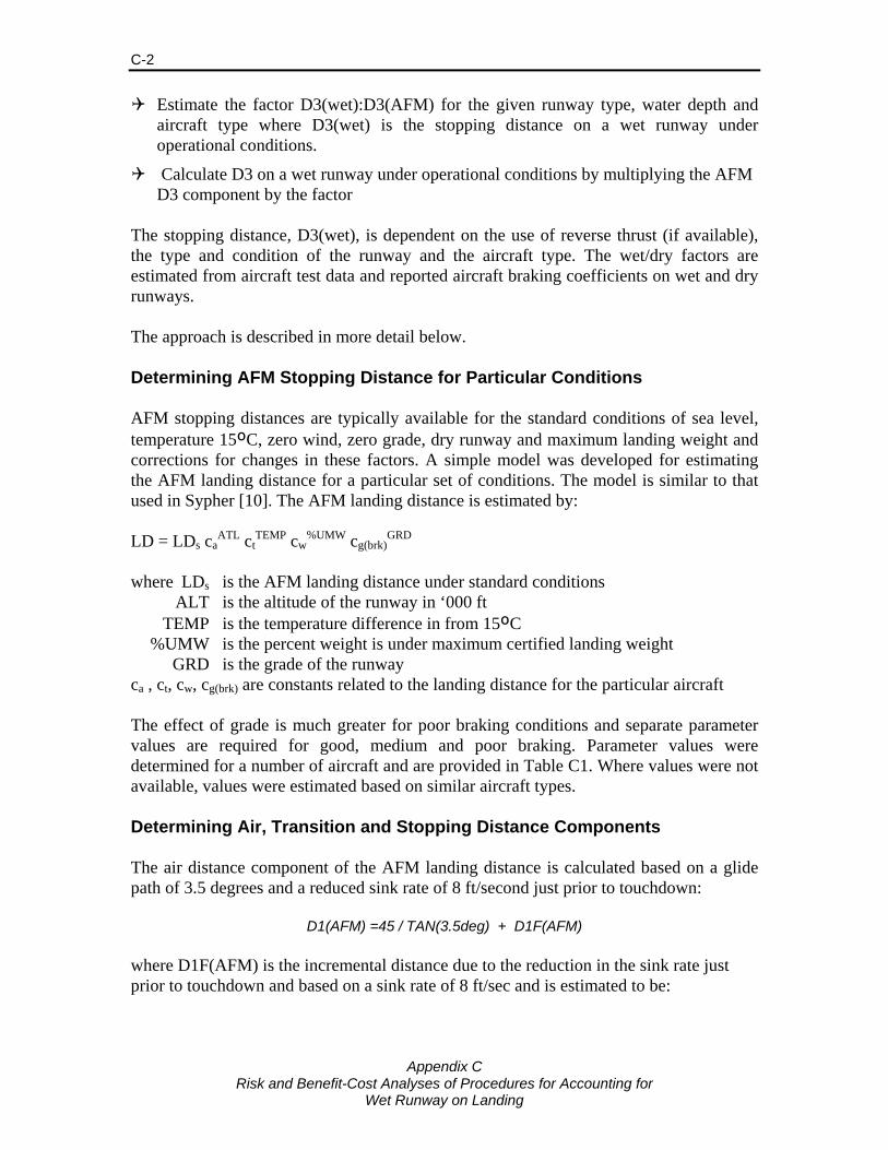
Appendix C
Risk and Benefit-Cost Analyses of Procedures for Accounting for Wet Runway on Landing
C-2
Estimate the factor D3(wet):D3(AFM) for the given runway type, water depth and aircraft type where D3(wet) is the stopping distance on a wet runway under operational conditions.
Calculate D3 on a wet runway under operational conditions by multiplying the AFM D3 component by the factor
The stopping distance, D3(wet), is dependent on the use of reverse thrust (if available), the type and condition of the runway and the aircraft type. The wet/dry factors are estimated from aircraft test data and reported aircraft braking coefficients on wet and dry runways. The approach is described in more detail below. Determining AFM Stopping Distance for Particular Conditions AFM stopping distances are typically available for the standard conditions of sea level, temperature 15ºC, zero wind, zero grade, dry runway and maximum landing weight and corrections for changes in these factors. A simple model was developed for estimating the AFM landing distance for a particular set of conditions. The model is similar to that used in Sypher [10]. The AFM landing distance is estimated by: LD = LDs ca
ATL ctTEMP cw
%UMW cg(brk)GRD
where LDs is the AFM landing distance under standard conditions ALT is the altitude of the runway in ‘000 ft TEMP is the temperature difference in from 15ºC %UMW is the percent weight is under maximum certified landing weight GRD is the grade of the runway ca , ct, cw, cg(brk) are constants related to the landing distance for the particular aircraft The effect of grade is much greater for poor braking conditions and separate parameter values are required for good, medium and poor braking. Parameter values were determined for a number of aircraft and are provided in Table C1. Where values were not available, values were estimated based on similar aircraft types. Determining Air, Transition and Stopping Distance Components The air distance component of the AFM landing distance is calculated based on a glide path of 3.5 degrees and a reduced sink rate of 8 ft/second just prior to touchdown:
D1(AFM) =45 / TAN(3.5deg) + D1F(AFM) where D1F(AFM) is the incremental distance due to the reduction in the sink rate just prior to touchdown and based on a sink rate of 8 ft/sec and is estimated to be:
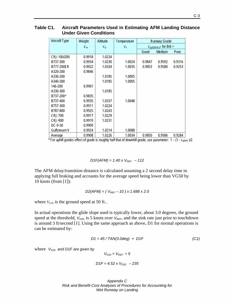
Appendix C
Risk and Benefit-Cost Analyses of Procedures for Accounting for Wet Runway on Landing
C-3
Table C1. Aircraft Parameters Used in Estimating AFM Landing Distance Under Given Conditions
Weight Altitude Temperature Runway Grade cw ca ct cgd(Brk)* for Brk =
Aircraft Type
Good Medium Poor CRJ-100/200 0.9918 1.0234 B737-300 0.9934 1.0230 1.0024 0.9847 0.9592 0.9316 B777-200ER 0.9922 1.0334 1.0035 0.9853 0.9580 0.9253 A320-200 0.9846 A330-200 1.0185 1.0005 A340-300 1.0185 1.0005 146-200 0.9901 A330-300 1.0185 B737-200^ 0.9835 B737-400 0.9935 1.0337 1.0048 B757-300 0.9911 1.0224 B787-800 0.9925 1.0243 CRJ-700 0.9917 1.0229 CRJ-900 0.9919 1.0231 DC-9-30 0.9909 Gulfstream V 0.9924 1.0214 1.0088 Average 0.9908 1.0226 1.0034 0.9850 0.9586 0.9284
* For uphill grades effect of grade is roughly half that of downhill grade, use parameter: 1 – (1 - cg(brk) )/2
D1F(AFM) = 1.40 x VREF – 112 The AFM delay/transition distance is calculated assuming a 2 second delay time in applying full braking and accounts for the average speed being lower than VG50 by 10 knots (from [1]):
D2(AFM) = ( VREF – 10 ) x 1.688 x 2.0 where VG50 is the ground speed at 50 ft.. In actual operations the glide slope used is typically lower, about 3.0 degrees, the ground speed at the threshold, VG50, is 5 knots over VREF, and the sink rate just prior to touchdown is around 3 ft/second [1]. Using the same approach as above, D1 for normal operations is can be estimated by: D1 = 45 / TAN(3.0deg) + D1F (C1) where VG50 and D1F are given by
VG50 = VREF + 5
D1F = 4.52 x VG50 – 235
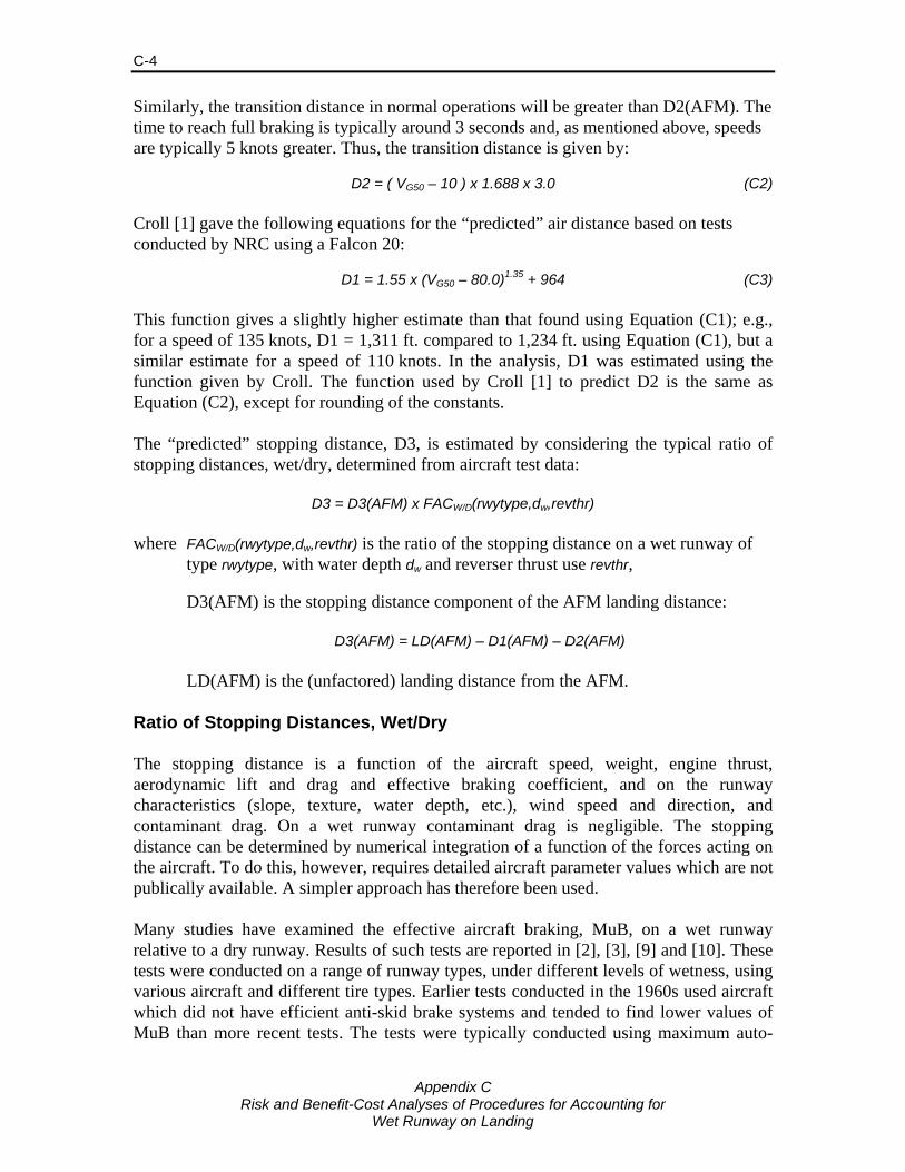
Appendix C
Risk and Benefit-Cost Analyses of Procedures for Accounting for Wet Runway on Landing
C-4
Similarly, the transition distance in normal operations will be greater than D2(AFM). The time to reach full braking is typically around 3 seconds and, as mentioned above, speeds are typically 5 knots greater. Thus, the transition distance is given by: D2 = ( VG50 – 10 ) x 1.688 x 3.0 (C2) Croll [1] gave the following equations for the “predicted” air distance based on tests conducted by NRC using a Falcon 20: D1 = 1.55 x (VG50 – 80.0)1.35 + 964 (C3) This function gives a slightly higher estimate than that found using Equation (C1); e.g., for a speed of 135 knots, D1 = 1,311 ft. compared to 1,234 ft. using Equation (C1), but a similar estimate for a speed of 110 knots. In the analysis, D1 was estimated using the function given by Croll. The function used by Croll [1] to predict D2 is the same as Equation (C2), except for rounding of the constants. The “predicted” stopping distance, D3, is estimated by considering the typical ratio of stopping distances, wet/dry, determined from aircraft test data:
D3 = D3(AFM) x FACW/D(rwytype,dw,revthr) where FACW/D(rwytype,dw,revthr) is the ratio of the stopping distance on a wet runway of
type rwytype, with water depth dw and reverser thrust use revthr, D3(AFM) is the stopping distance component of the AFM landing distance:
D3(AFM) = LD(AFM) – D1(AFM) – D2(AFM)
LD(AFM) is the (unfactored) landing distance from the AFM. Ratio of Stopping Distances, Wet/Dry The stopping distance is a function of the aircraft speed, weight, engine thrust, aerodynamic lift and drag and effective braking coefficient, and on the runway characteristics (slope, texture, water depth, etc.), wind speed and direction, and contaminant drag. On a wet runway contaminant drag is negligible. The stopping distance can be determined by numerical integration of a function of the forces acting on the aircraft. To do this, however, requires detailed aircraft parameter values which are not publically available. A simpler approach has therefore been used. Many studies have examined the effective aircraft braking, MuB, on a wet runway relative to a dry runway. Results of such tests are reported in [2], [3], [9] and [10]. These tests were conducted on a range of runway types, under different levels of wetness, using various aircraft and different tire types. Earlier tests conducted in the 1960s used aircraft which did not have efficient anti-skid brake systems and tended to find lower values of MuB than more recent tests. The tests were typically conducted using maximum auto-
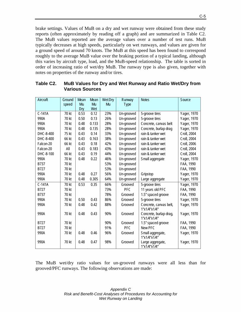
Appendix C
Risk and Benefit-Cost Analyses of Procedures for Accounting for Wet Runway on Landing
C-5
brake settings. Values of MuB on a dry and wet runway were obtained from these study reports (often approximately by reading off a graph) and are summarized in Table C2. The MuB values reported are the average values over a number of test runs. MuB typically decreases at high speeds, particularly on wet runways, and values are given for a ground speed of around 70 knots. The MuB at this speed has been found to correspond roughly to the average MuB value over the braking portion of a typical landing, although this varies by aircraft type, load, and the MuB-speed relationship. The table is sorted in order of increasing ratio of wet/dry MuB. The runway type is also given, together with notes on properties of the runway and/or tires. Table C2. MuB Values for Dry and Wet Runway and Ratio Wet/Dry from
Various Sources
Aircraft Ground speed
Mean Mu Dry
Mean Mu Wet
Wet:Dry Mu
Runway Type
Notes Source
C-141A 70 kt 0.53 0.12 23% Un-grooved 5-groove tires Yager, 1970 990A 70 kt 0.50 0.13 26% Un-grooved 5-groove tires Yager, 1970 990A 70 kt 0.48 0.133 28% Un-grooved Concrete, canvas belt Yager, 1970 990A 70 kt 0.48 0.135 28% Un-grooved Concrete, burlap drag Yager, 1970 DHC-8-400 75 kt 0.43 0.14 33% Un-grooved rain & tanker wet Croll, 2004 DHC-8-400 66 kt 0.43 0.163 38% Un-grooved rain & tanker wet Croll, 2004 Falcon-20 66 kt 0.43 0.18 42% Un-grooved rain & tanker wet Croll, 2006 Falcon-20 All 0.43 0.183 43% Un-grooved rain & tanker wet Croll, 2004 DHC-8-100 66 kt 0.43 0.19 44% Un-grooved rain & tanker wet Croll, 2004 990A 70 kt 0.48 0.22 46% Un-grooved Small aggregate Yager, 1970 B737 70 kt 53% Un-grooved FAA, 1990 B727 70 kt 53% Un-grooved FAA, 1990 990A 70 kt 0.48 0.27 56% Un-grooved Gripstop Yager, 1970 990A 70 kt 0.48 0.305 64% Un-grooved Large aggregate Yager, 1970 C-141A 70 kt 0.53 0.35 66% Grooved 5-groove tires Yager, 1970 B727 70 kt 73% PFC 11 years old PFC FAA, 1990 B737 70 kt 78% Grooved 1.5" spaced groove FAA, 1990 990A 70 kt 0.50 0.43 86% Grooved 5-groove tires Yager, 1970 990A 70 kt 0.48 0.42 88% Grooved Concrete, canvas belt,
1"x1/4"x1/4" Yager, 1970
990A 70 kt 0.48 0.43 90% Grooved Concrete, burlap drag, 1"x1/4"x1/4"
Yager, 1970
B727 70 kt 90% Grooved 1.5" spaced groove FAA, 1990 B727 70 kt 91% PFC New PFC FAA, 1990 990A 70 kt 0.48 0.46 96% Grooved Small aggregate,
1"x1/4"x1/4" Yager, 1970
990A 70 kt 0.48 0.47 98% Grooved Large aggregate, 1"x1/4"x1/4"
Yager, 1970
The MuB wet/dry ratio values for un-grooved runways were all less than for grooved/PFC runways. The following observations are made:

Appendix C
Risk and Benefit-Cost Analyses of Procedures for Accounting for Wet Runway on Landing
C-6
Values on un-grooved runways varied from 23% to 64% and on grooved/PFC runways varied from 66% to 98%
The highest values on both un-grooved and grooved runways was on an asphalt runway with large aggregate (thus high texture)
All values less than 30% were obtained in the older tests where anti-skid brakes were not used.
The ratio of about 53% obtained in the FAA/NASA tests on un-grooved runways using 727 and 737 aircraft were higher than those found by Croll using FA-20 and DHC-8 aircraft.
The value on an old PFC runway was lower than most grooved and PFC runways, while the value on a new PFC runways was one of the higher values.
The wet:dry MuB ratios vary much more by runway type and wetness condition than they do by aircraft type.
These results are generally consistent with other earlier results reported in Yager (1970). More in depth comparisons are not warranted due to the lack of detailed information on the runway texture in many of those tests. However, two tests on PFC runways gave ratios of 0.85 and 0.89, both between the two values reported in Table C2. Values of the ratio of wet:dry MuB have been accepted for use in certification of aircraft. Table C3 gives the values of the ratio used in the UK CAA certification of Boeing aircraft types. The runway these values are applicable to was described as “smooth wet runways”. The value of 50% used for current certification is slightly lower than the values found in the FAA tests using a 727 and 737, but higher than the values found by Croll for the FA-20 and DHC-8 aircraft tested. Table C3. Ratio of MuB Wet:Dry Used in the UK CAA Certification of
Boeing Aircraft Types
Aircraft Ratio MuB Wet:Dry B737-200, Goodyear A/S 45% B707 50% B727-200 50% B747-100 55% B737-200, Mark III A/S 60% Later aircraft certifications 50%
Source: Giesman [11] The FAA and JAA regulations allow the calculation of stopping distance in determining aircraft accelerate-stop performance on takeoff to use a higher braking coefficient of friction for runway surfaces that have been grooved or treated with PFC material. On these runways, a wet runway baking coefficient of 70% of the dry runway braking coefficient may be used. Alternatively, another method specified in the regulations may be used to determine the wet runway braking coefficient. The 70% of dry MuB
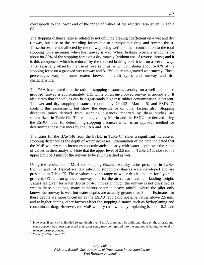
Appendix C
Risk and Benefit-Cost Analyses of Procedures for Accounting for Wet Runway on Landing
C-7
corresponds to the lower end of the range of values of the wet:dry ratio given in Table C2. The stopping distance ratio is related to not only the braking coefficient on a wet and dry runway, but also to the retarding forces due to aerodynamic drag and reverse thrust. These forces are not affected by the runway being wet2 and their contribution to the total stopping force increases when the runway is wet. Wheel braking typically accounts for about 80-85% of the stopping force on a dry runway (without use of reverse thrust) and it is this component which is reduced by the reduced braking coefficient on a wet runway. This is partially offset by the use of reverse thrust which contributes about 5-10% of the stopping force on a grooved wet runway and 8-12% on an un-grooved wet runway. These percentages vary to some extent between aircraft types and runway and tire characteristics. The FAA have stated that the ratio of stopping distances, wet:dry, on a well maintained grooved runway is approximately 1.15 while on an un-grooved runway is around 2.0. It also states that the values can be significantly higher if rubber contamination is present. The wet and dry stopping distances reported by Croll[2], Martin [5] and ESDU[7] confirm this assessment, but show the dependence on other factors also. Stopping distances ratios derived from stopping distances reported by these studies are summarized in Table C4. The values given by Martin and the ESDU are derived using the ESDU model for determining stopping distances which is an approved method for determining these distances by the FAA and JAA. The ratios for the BAe-146 from the ESDU in Table C4 show a significant increase in stopping distances as the depth of water increases. Examination of the data indicated that the MuB wet:dry ratio increases approximately linearly with water depth over the range of values in their analysis. Note that the upper level of 2.5 mm in Table C4 is close to the upper limit of 3 mm for the runway to be still classified as wet. Using the results of the MuB and stopping distance wet:dry ratios presented in Tables C2, C3 and C4, typical wet:dry ratios of stopping distances were developed and are presented in Table C5. These values cover a range of water depths and are for “typical” grooved/PFC and un-grooved runways and for the aircraft at maximum landing weight. Values are given for water depths of 4-8 mm as although the runway is not classified as wet in these situations, many accidents occur in heavy rainfall where the pilot only knows the runway is wet, but water depths are actually greater than 3 mm. Estimates for these depths are more uncertain as the ESDU report did not give values above 2.5 mm, and at higher depths, other factors affect the stopping distance such as hydroplaning and contaminant drag. However, the MuB wet:dry ratio when hydroplaning is about 0.23 and
2 However, if runway is flooded (water depth over 3 mm), there may be additional drag on the aircraft and
some concern has been expressed that water spray may be ingested into the engines affecting the level of reverse thrust produced.
3 Yager (1970) Figure 27
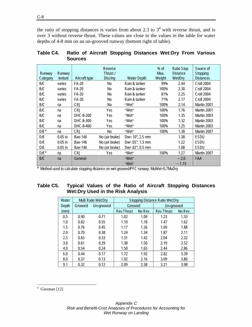
Appendix C
Risk and Benefit-Cost Analyses of Procedures for Accounting for Wet Runway on Landing
C-8
the ratio of stopping distances is varies from about 2.3 to 34 with reverse thrust, and is over 3 without reverse thrust. These values are close to the values in the table for water depths of 4-8 mm on an un-grooved runway (bottom right of table). Table C4. Ratio of Aircraft Stopping Distances Wet:Dry From Various
Sources
Runway Category
Runway texture Aircraft type
Reverse Thrust / Discing Water Depth
% of Max.
Weight
Ratio Stop Distance Wet/Dry
Source of Stopping Distances
B/C varies FA-20 No Rain & tanker 99% 2.44 Croll 2004 B/C varies FA-20 No Rain & tanker 100% 2.30 Croll 2004 B/C varies FA-20 No Rain & tanker 81% 2.25 Croll 2004 B/C varies FA-20 No Rain & tanker 71% 2.17 Croll 2004 B/C na CRJ No “Wet” 100% 2.14 Martin 2001 B/C na CRJ Yes “Wet” 100% 1.76 Martin 2001 B/C na DHC-8-200 Yes “Wet” 100% 1.35 Martin 2003 B/C na DHC-8-300 Yes “Wet” 100% 1.32 Martin 2003 B/C na DHC-8-400 Yes “Wet” 100% 1.25 Martin 2003 D/E* na CRJ No “Wet” 100% 1.38 Martin 2007 D/E 0.05 in Bae-146 No (air brake) Dw=.10", 2.5 mm 1.38 ESDU D/E 0.05 in Bae-146 No (air brake) Dw=.05", 1.3 mm 1.22 ESDU D/E 0.05 in Bae-146 No (air brake) Dw=.02", 0.5 mm 1.08 ESDU D/E* na CRJ Yes “Wet” 100% 1.27 Martin 2007 B/C na General “Wet” ~ 2.0 FAA “Wet” ~ 1.15
* Method used to calculate stopping distance on wet grooved/PFC runway: MuWet=0.7MuDry Table C5. Typical Values of the Ratio of Aircraft Stopping Distances
Wet:Dry Used in the Risk Analysis
Water MuB Ratio Wet:Dry Stopping Distance Ratio Wet:Dry Depth Grooved Un-grooved Grooved Un-grooved (mm) Rev.Thrust No Rev. Rev.Thrust No Rev. 0.5 0.90 0.71 1.02 1.09 1.23 1.33 1.0 0.82 0.55 1.10 1.18 1.47 1.62 1.5 0.76 0.45 1.17 1.26 1.69 1.88 2.0 0.70 0.38 1.24 1.34 1.87 2.11 2.5 0.65 0.33 1.31 1.42 2.04 2.32 3.0 0.61 0.29 1.38 1.50 2.19 2.52 4.0 0.54 0.24 1.50 1.65 2.44 2.86 6.0 0.44 0.17 1.72 1.92 2.82 3.39 8.0 0.37 0.13 1.92 2.16 3.09 3.80 9.1 0.32 0.12 2.09 2.38 3.21 3.98
4 Giesman [12]

Appendix C
Risk and Benefit-Cost Analyses of Procedures for Accounting for Wet Runway on Landing
C-9
The MuB wet:dry ratio values of 0.5 used for aircraft certification for landings on all runways correspond roughly to water depths of 4 mm on a grooved runway and 1-1.5 mm on an un-grooved runway, while the value of 0.7 used for takeoff on grooved runways corresponds to a water depth of 2.0 mm. The risk analysis uses the typical values given in Table C5 to estimate the stopping distance component D3, but allows for variation around these typical values to account for variation in factors accounted for in the AFM LD (e.g., aircraft weight, airport altitude, temperature, etc.) and other factors such as runway texture (apart from grooving), runway rubber contamination, aircraft drag and reverse thrust level, tire wear, initial speed, etc. Variation due to these other factors is discussed in the next section. The ratios of Wet:dry stopping distances vary with known factors such as the weight of the aircraft, altitude and temperature. For example, the heavier the load, the greater proportion of the stopping distance due to wheel braking and thus the greater the wet:dry ratio. This is evident in the results for the FA-20 in Table C4 where the ratio is 2.3-2.4 near maximum landing weight, and 2.17 when at 71% of the maximum weight. Using the results of the CRJ and FA-20 aircraft, a relationship was developed between the Wet:Dry stopping distance ratio and the AFM LD for use in the risk model when determining D3. The adjusted values for different AFM landing distances and ratios maximum landing weight and ISA conditions are given in Table C6. Table C6. Adjustment to the Ratio of Aircraft Stopping Distances
Wet:Dry to Account for Aircraft Weight, Altitude and Temperature
% of AFM LD at Max LD Weight
Adjusted Ratio for Landing Weight Given Ratio at 100% of Max. Landing Weight (from Table C5) of:
100% 1.25 1.50 1.75 2.00 2.25 2.50 90% 1.24 1.48 1.72 1.96 2.20 2.44 80% 1.23 1.46 1.69 1.92 2.15 2.38 70% 1.22 1.44 1.66 1.88 2.10 2.32 60% 1.21 1.42 1.63 1.84 2.05 2.26
Values of VREF and VG50 vary between aircraft types and from landing to landing. However, for most jet aircraft VG50 ranges between 120 and 150 knots and VG50 is approximately 5 knots less than VREF. Zero headwind is assumed in the analysis of the risks. Speeds are generally less for the short landing distance aircraft. Categories of Rainfall Rates The common rainfall categories of light, moderate, heavy and very heavy were used in the model. As shown in Table 2.2, rainfall rates can vary significantly within a category, especially at the higher rainfall rates. The Heavy and Very Heavy categories were each divided into three (lower, medium and upper) categories. In addition, an Extremely Heavy category was added to account for infrequent periods of torrential rainfall that can
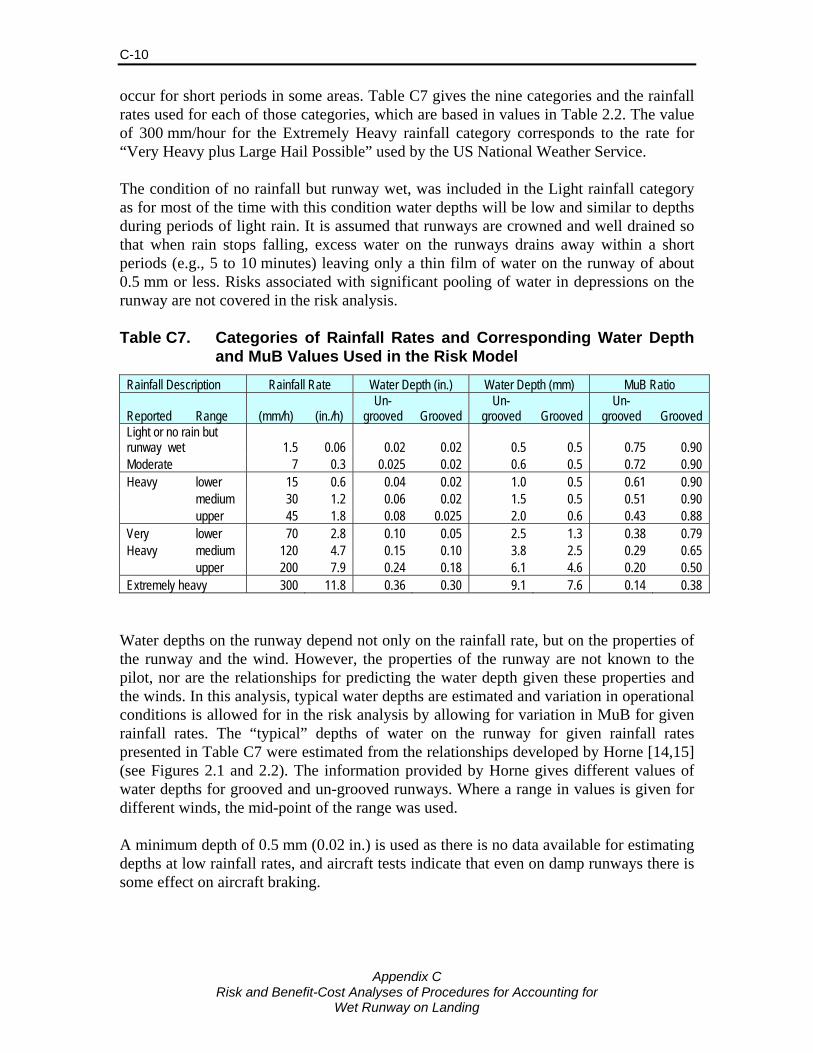
Appendix C
Risk and Benefit-Cost Analyses of Procedures for Accounting for Wet Runway on Landing
C-10
occur for short periods in some areas. Table C7 gives the nine categories and the rainfall rates used for each of those categories, which are based in values in Table 2.2. The value of 300 mm/hour for the Extremely Heavy rainfall category corresponds to the rate for “Very Heavy plus Large Hail Possible” used by the US National Weather Service. The condition of no rainfall but runway wet, was included in the Light rainfall category as for most of the time with this condition water depths will be low and similar to depths during periods of light rain. It is assumed that runways are crowned and well drained so that when rain stops falling, excess water on the runways drains away within a short periods (e.g., 5 to 10 minutes) leaving only a thin film of water on the runway of about 0.5 mm or less. Risks associated with significant pooling of water in depressions on the runway are not covered in the risk analysis. Table C7. Categories of Rainfall Rates and Corresponding Water Depth
and MuB Values Used in the Risk Model
Rainfall Description Rainfall Rate Water Depth (in.) Water Depth (mm) MuB Ratio
Reported Range (mm/h) (in./h) Un-
grooved Grooved Un-
grooved Grooved Un-
grooved Grooved Light or no rain but runway wet 1.5 0.06 0.02 0.02 0.5 0.5 0.75 0.90 Moderate 7 0.3 0.025 0.02 0.6 0.5 0.72 0.90 Heavy lower 15 0.6 0.04 0.02 1.0 0.5 0.61 0.90 medium 30 1.2 0.06 0.02 1.5 0.5 0.51 0.90 upper 45 1.8 0.08 0.025 2.0 0.6 0.43 0.88 Very lower 70 2.8 0.10 0.05 2.5 1.3 0.38 0.79 Heavy medium 120 4.7 0.15 0.10 3.8 2.5 0.29 0.65 upper 200 7.9 0.24 0.18 6.1 4.6 0.20 0.50 Extremely heavy 300 11.8 0.36 0.30 9.1 7.6 0.14 0.38
Water depths on the runway depend not only on the rainfall rate, but on the properties of the runway and the wind. However, the properties of the runway are not known to the pilot, nor are the relationships for predicting the water depth given these properties and the winds. In this analysis, typical water depths are estimated and variation in operational conditions is allowed for in the risk analysis by allowing for variation in MuB for given rainfall rates. The “typical” depths of water on the runway for given rainfall rates presented in Table C7 were estimated from the relationships developed by Horne [14,15] (see Figures 2.1 and 2.2). The information provided by Horne gives different values of water depths for grooved and un-grooved runways. Where a range in values is given for different winds, the mid-point of the range was used. A minimum depth of 0.5 mm (0.02 in.) is used as there is no data available for estimating depths at low rainfall rates, and aircraft tests indicate that even on damp runways there is some effect on aircraft braking.
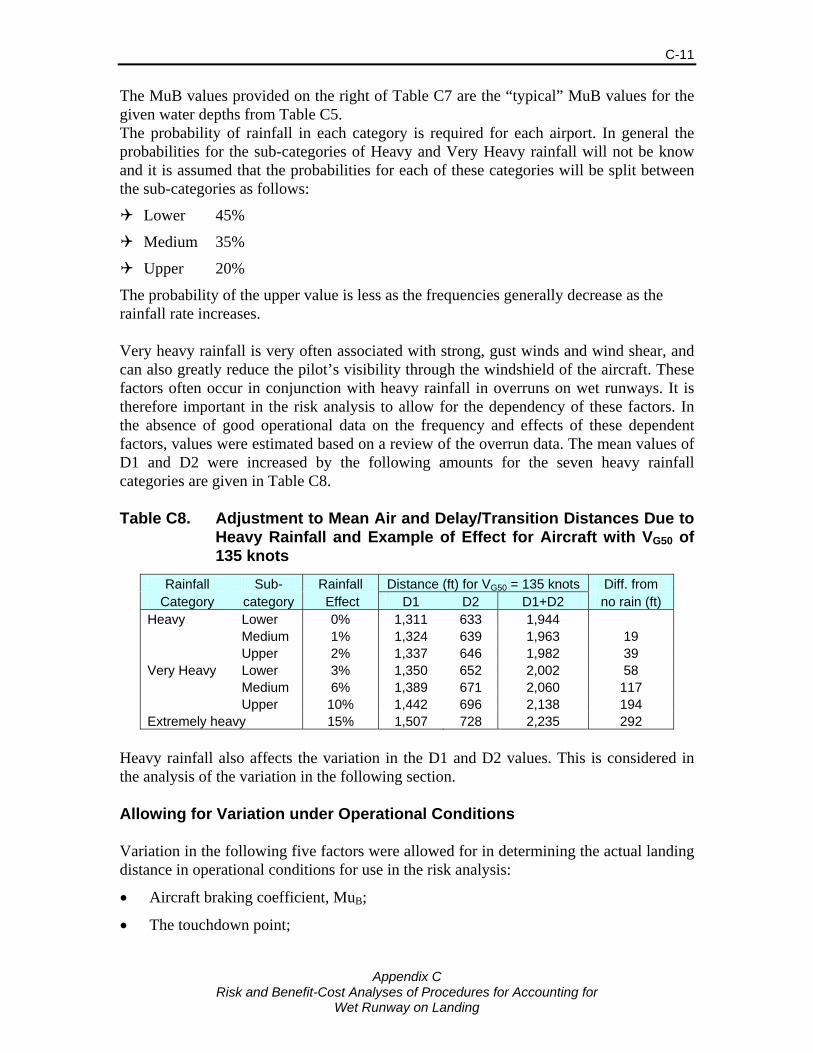
Appendix C
Risk and Benefit-Cost Analyses of Procedures for Accounting for Wet Runway on Landing
C-11
The MuB values provided on the right of Table C7 are the “typical” MuB values for the given water depths from Table C5. The probability of rainfall in each category is required for each airport. In general the probabilities for the sub-categories of Heavy and Very Heavy rainfall will not be know and it is assumed that the probabilities for each of these categories will be split between the sub-categories as follows:
Lower 45%
Medium 35%
Upper 20%
The probability of the upper value is less as the frequencies generally decrease as the rainfall rate increases. Very heavy rainfall is very often associated with strong, gust winds and wind shear, and can also greatly reduce the pilot’s visibility through the windshield of the aircraft. These factors often occur in conjunction with heavy rainfall in overruns on wet runways. It is therefore important in the risk analysis to allow for the dependency of these factors. In the absence of good operational data on the frequency and effects of these dependent factors, values were estimated based on a review of the overrun data. The mean values of D1 and D2 were increased by the following amounts for the seven heavy rainfall categories are given in Table C8. Table C8. Adjustment to Mean Air and Delay/Transition Distances Due to
Heavy Rainfall and Example of Effect for Aircraft with VG50 of 135 knots
Rainfall Sub- Rainfall Distance (ft) for VG50 = 135 knots Diff. from Category category Effect D1 D2 D1+D2 no rain (ft)
Heavy Lower 0% 1,311 633 1,944 Medium 1% 1,324 639 1,963 19 Upper 2% 1,337 646 1,982 39 Very Heavy Lower 3% 1,350 652 2,002 58 Medium 6% 1,389 671 2,060 117 Upper 10% 1,442 696 2,138 194 Extremely heavy 15% 1,507 728 2,235 292
Heavy rainfall also affects the variation in the D1 and D2 values. This is considered in the analysis of the variation in the following section. Allowing for Variation under Operational Conditions Variation in the following five factors were allowed for in determining the actual landing distance in operational conditions for use in the risk analysis:
• Aircraft braking coefficient, MuB;
• The touchdown point;
Appendix C
Risk and Benefit-Cost Analyses of Procedures for Accounting for Wet Runway on Landing
C-12
• The delay time in applying brakes;
• The difference between the actual and planned speed at touchdown; and
• The change in MuB due to error in setting braking, braking malfunction or due to worn brakes.
Variation in Aircraft Braking Coefficient The factor used to adjust the stopping distance for the wet runway provides an average adjustment factor to account for the runway wetness, runway grooving/PFC, reverse thrust and other known factors influencing the LD. The factor only represents average conditions, and variation in the actual stopping distance will occur both due to variations in these factors, as well as variation between aircraft (aerodynamic drag, tire pressure & wear, etc.) and runways (texture, rubber contamination, etc.). Estimates of the braking coefficient have been determined from many aircraft types using different aircraft, runways and degrees of wetness (e.g., values given in Table C2). The variation in these estimates around the expected value given the runway type (un-grooved or grooved/PFC) and use of reverse thrust provides an indication of the uncontrolled variation in MuB. The study by Sypher examining the risks on slippery runways [10] analysed the results of the tests conducted at North Bay using the FA-20 [1] and found the standard deviation of MuB on a dry runway to be 0.0375, or 9.2% of the mean MuB value on a dry runway. Martin [5] used a value of 11% in the Monte Carlo analysis, and an analysis of the EDSU results [7] gave a value of 13% for a BAe 146 aircraft. In the current study, a value for the SD in MuB of 11% is used for dry runways, excluding variation caused by incorrect setting or malfunction of the brakes. In the analysis of the wet runway tests of the FA-20 by Croll [2], MuB values on a dry runway averaged 0.43 and on a wet un-grooved runway varied between 0.105 and 0.26 over the 40 tests. The standard deviation of MuB on a wet runway was 0.037, or 20% of the average MuB value. The tests covered runways with various levels of texture, one had significant rubber contamination, and varying degrees of wetness, but all were un-grooved runways. Analysis of results of tests using DHC-8 series aircraft all on the same un-grooved runway [3] gave a standard deviation in MuB of only 5-8% of the average MuB on a wet runway. The ESDU analysis [7] gave graphs of the MuB values for water depths ranging from zero (dry) to 0.3 in. (7.6 mm) for a BAe 146 aircraft landing on a grooved runway with texture depth of 0.05 in. The variation in MuB over the range of wetness values corresponds to a standard deviation of approximately 0.045 at 60 knots. On an un-grooved runway, the variation due to water depth is found to be slightly greater, 0.06, based on values given in Table C4. These correspond, approximately to 10% and 20% of

Appendix C
Risk and Benefit-Cost Analyses of Procedures for Accounting for Wet Runway on Landing
C-13
the average MuB on grooved and un-grooved runways, respectively. Thus, the water depth is an important contributor to the variation in MuB values. Analysis of the estimated MuB values from NASA/FAA tests reported by [8] indicates that the standard deviation in MuB on wet PFC runways is approximately 9% of the typical MuB value. This variation based on 3 tests using a B727 aircraft on two PFC runways, one new and the other 11 years old. Most of the variation is likely due to the differences in the condition of the PFC runways. Martin [5], in his Monte Carlo analysis, assumed that the standard deviation of MuB on a wet runway was 15% of the MuB value determined using the ESDU method. The paper also states that, using ESDU data, the expected minimum and maximum values, determined at a rate of 100 knots, are estimated to be 0.6 to 1.55. Assuming these correspond to a 99% confidence interval, a standard deviation of 15% would give a range of values of 0.55 to 1.45. These are close to the values used by Martin, but the lower value is a little lower than the minimum of 0.6 given by the ESDU. Based on the analysis of the variation, the standard deviation of MuB for a wet runway for given water depths (i.e., excluding the variation caused by the depth of water) used in the analysis was: SD = 0.030 for grooved and PFC runways (8% of typical MuB wet value) = 0.033 for un-grooved and non-PFC runways (13% of typical MuB wet value) The standard deviation of the ratio, MuB wet:dry, is found by dividing by the typical MuB dry value. Assuming a MuB dry value of 0.5, the SDs are 0.060 and 0.066 for grooved/PFC and un-grooved runways respectively. It was assumed that the ratio follows a normal distribution with the mean value determined from Tables C3, C4 and C7 for a given runway type, water depth and the AFM landing distances, and the above standard deviation.5 The probability distributions for a range of water depths are provided in Figure C1. Variation in Touchdown Point The variation in the touchdown point which affects the air distance, D1, was set based on the results found by Croll [1], the ESDU [7] and Martin [5,6], but supplemented by information from the accident/incident data. The latter data were used to set the distribution for touchdown points well beyond the target point (i.e., the touchdown point assumed in determining the AFM landing distance typically about 1,500 ft. from the runway threshold for jet aircraft) which are critical in determining the risks.
5 Where the probability of the MuB wet:dry ratio was greater than 1, the ratio was restricted 1.0 and the probability scaled so that the sum over all values of the ratio equaled 1.0

Appendix C
Risk and Benefit-Cost Analyses of Procedures for Accounting for Wet Runway on Landing
C-14
0.00
0.01
0.02
0.03
0.04
0.05
0.06
0.07
0.08
0.0 0.1 0.2 0.3 0.4 0.5 0.6 0.7 0.8 0.9 1.0
MuB Ratio Wet/Dry
Prob
abili
ty*
Grooved/PFC,w d = 0.5mm
Grooved/PFC,w d = 1.5mm
Grooved/PFC,w d = 4.0mm
Un-grooved,w d = 0.5mm
Un-grooved,w d = 1.5mm
Un-grooved,w d = 4.0mm
* Probabiliy o f being within ± 0.005 of M uB Wet:Dry ratio value
Figure C1 Probability Distribution of Ratio Wet:Dry of Mu Braking for
Given Runway Type and Water Depth (wd) Croll estimated the standard deviation of the air distance, SD(D1) to be a function of VG50.
SD(D1) = (VG50 – 6.16) x 1.688 x 1.72 /2 The standard deviation predicted using this formula is similar to, but less than, the SD in D1 given by ESDU in [7]. For example, the SD for a BAe 146 given by ESDU is 196 ft. compared to a value of 180 ft. given by the above equation (assuming VG50 = VREF + 5), but the value for the B737 is 194 ft. is close to the ESDU BAe 146 value. Martin [5,6] included variation in the threshold off-set distance (SD = 100 ft), glide path (SD = 0.2) degrees, the sink rate (SD = 2ft/sec) and VREF (SD = 50% of reported headwind). Using these parameters, the SD of D16 in the Monte Carlo analysis for the different aircraft examined were:
218 ft. for a 50-seat RJ (VREF = 142 kts)
230 ft. for 78-seat turboprop (VREF = 120 kts)
174 ft. for 39-seat turboprop(VREF = 92 kts)
The SD values used by the ESDU and Martin are not consistent with the formula used by Croll, in particular the increasing value with increased speed. The variation in D1 values would be expected to increase with increasing speed as the aircraft will travel further
6 Martin divided the D1 distance into two components, D0 and D1, where D0 is the distance from the threshold at height of 50 ft, and gave the SD for both D0 and D1. The SD for the combined total was found by the square root of: [ SD(D0)2 + SD(D1)2 ]
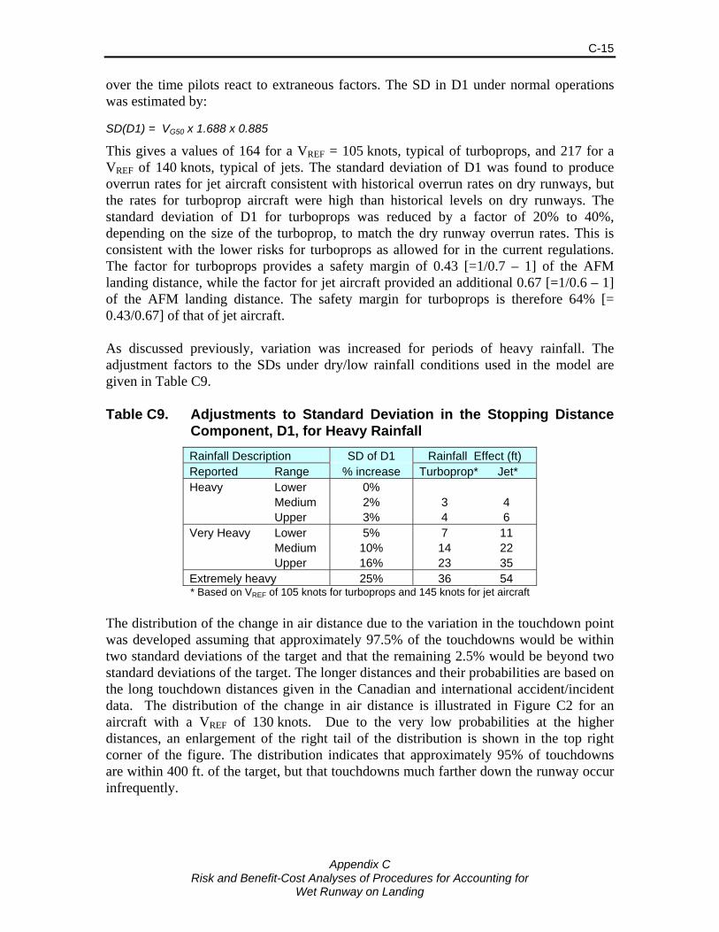
Appendix C
Risk and Benefit-Cost Analyses of Procedures for Accounting for Wet Runway on Landing
C-15
over the time pilots react to extraneous factors. The SD in D1 under normal operations was estimated by:
SD(D1) = VG50 x 1.688 x 0.885
This gives a values of 164 for a VREF = 105 knots, typical of turboprops, and 217 for a VREF of 140 knots, typical of jets. The standard deviation of D1 was found to produce overrun rates for jet aircraft consistent with historical overrun rates on dry runways, but the rates for turboprop aircraft were high than historical levels on dry runways. The standard deviation of D1 for turboprops was reduced by a factor of 20% to 40%, depending on the size of the turboprop, to match the dry runway overrun rates. This is consistent with the lower risks for turboprops as allowed for in the current regulations. The factor for turboprops provides a safety margin of 0.43 [=1/0.7 – 1] of the AFM landing distance, while the factor for jet aircraft provided an additional 0.67 [=1/0.6 – 1] of the AFM landing distance. The safety margin for turboprops is therefore 64% [= 0.43/0.67] of that of jet aircraft. As discussed previously, variation was increased for periods of heavy rainfall. The adjustment factors to the SDs under dry/low rainfall conditions used in the model are given in Table C9. Table C9. Adjustments to Standard Deviation in the Stopping Distance
Component, D1, for Heavy Rainfall
Rainfall Description SD of D1 Rainfall Effect (ft) Reported Range % increase Turboprop* Jet* Heavy Lower 0% Medium 2% 3 4 Upper 3% 4 6 Very Heavy Lower 5% 7 11 Medium 10% 14 22 Upper 16% 23 35 Extremely heavy 25% 36 54 * Based on VREF of 105 knots for turboprops and 145 knots for jet aircraft
The distribution of the change in air distance due to the variation in the touchdown point was developed assuming that approximately 97.5% of the touchdowns would be within two standard deviations of the target and that the remaining 2.5% would be beyond two standard deviations of the target. The longer distances and their probabilities are based on the long touchdown distances given in the Canadian and international accident/incident data. The distribution of the change in air distance is illustrated in Figure C2 for an aircraft with a VREF of 130 knots. Due to the very low probabilities at the higher distances, an enlargement of the right tail of the distribution is shown in the top right corner of the figure. The distribution indicates that approximately 95% of touchdowns are within 400 ft. of the target, but that touchdowns much farther down the runway occur infrequently.
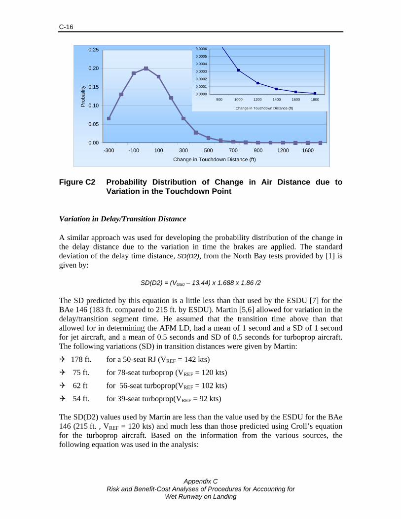
Appendix C
Risk and Benefit-Cost Analyses of Procedures for Accounting for Wet Runway on Landing
C-16
0.00
0.05
0.10
0.15
0.20
0.25
-300 -100 100 300 500 700 900 1200 1600
Change in Touchdown Distance (ft)
Pro
baili
ty
0.0000
0.0001
0.0002
0.0003
0.0004
0.0005
0.0006
900 1000 1200 1400 1600 1800
Change in Touchdown Distance (ft)
Figure C2 Probability Distribution of Change in Air Distance due to Variation in the Touchdown Point
Variation in Delay/Transition Distance A similar approach was used for developing the probability distribution of the change in the delay distance due to the variation in time the brakes are applied. The standard deviation of the delay time distance, SD(D2), from the North Bay tests provided by [1] is given by:
SD(D2) = (VG50 – 13.44) x 1.688 x 1.86 /2 The SD predicted by this equation is a little less than that used by the ESDU [7] for the BAe 146 (183 ft. compared to 215 ft. by ESDU). Martin [5,6] allowed for variation in the delay/transition segment time. He assumed that the transition time above than that allowed for in determining the AFM LD, had a mean of 1 second and a SD of 1 second for jet aircraft, and a mean of 0.5 seconds and SD of 0.5 seconds for turboprop aircraft. The following variations (SD) in transition distances were given by Martin:
178 ft. for a 50-seat RJ (VREF = 142 kts)
75 ft. for 78-seat turboprop (VREF = 120 kts)
62 ft for 56-seat turboprop(VREF = 102 kts)
54 ft. for 39-seat turboprop(VREF = 92 kts) The SD(D2) values used by Martin are less than the value used by the ESDU for the BAe 146 (215 ft. , VREF = 120 kts) and much less than those predicted using Croll’s equation for the turboprop aircraft. Based on the information from the various sources, the following equation was used in the analysis:

Appendix C
Risk and Benefit-Cost Analyses of Procedures for Accounting for Wet Runway on Landing
C-17
SD(D2) = (VG50 – 30) x 1.688 x 1.86 for jet aircraft (VG50 – 30) x 1.688 x 1.86/2 for turboprop aircraft The SDs were increased for periods of heavy rainfall in the model and are given in Table C10. Table C10. Adjustments to Standard Deviation in the Transition Distance
Component, D2, for Heavy Rainfall
Rainfall Description Rainfall Effect Distance (ft) for Jet, VG50=140 knts Reported Range % SD of D2 Diff. from no rain Heavy Lower 0% 205
Medium 2% 209 4
Upper 3% 211 6 Very Heavy Lower 5% 215 10
Medium 10% 225 20
Upper 16% 237 33 Extremely Heavy 25% 256 51 The distribution of the change in delay distance was developed assuming that approximately 98% of the delay distances would be within two standard deviations of the target and that the remaining 2% would be beyond the target. The longer distances and their probabilities are based on the long delays in applying brakes as is occasionally noted in accident/incident reports. The probability distribution of the change in delay distance due to variation in the time of application of the brakes is shown in Figure C3 for a jet aircraft with VREF = 135 knots. Variation in Speed at Touchdown Under standard operating procedures, the equivalent airspeed at the threshold is normally VREF plus 5 knots plus a correction for head/tail wind speed. In practice speeds differ from the target speed due to factors such as variable winds and turbulence, and excessive speed is a common factor in landing overruns with speeds often being 15 knots higher than the target speed in overruns. Speeds are usually within 5 knots of the target speed, but higher values occur infrequently. The variation in speed is greater for aircraft with high landing speed. The risk model used six speed points to model the variation in speed with the difference from the target speed7 ranging from -3.8% to 15.4% of the target speed. Thus, for a target speed of 100 knots (typical of large turboprops), the variation ranged from -3.8 to 15.4 knots, and for a target speed of 130 knots (typical of jet aircraft), the variation ranged from -5.1 to 20.8 knots. Figure C4 gives the probability distribution of the difference between the target and actual speeds for an A320 used in the risk analysis. 7 The target speed is estimated by VREF + 5 – 10 , where the -10 allows for the reduction in speed
during the delay/transition segment.

Appendix C
Risk and Benefit-Cost Analyses of Procedures for Accounting for Wet Runway on Landing
C-18
0.0000
0.0500
0.1000
0.1500
0.2000
0.2500
-300 -200 -100 0 100 200 300 400 500 600 800 1,000 1,200
Change in Delay Distance (ft)
Prob
ailit
y
0.0002
0.00060.0016
0.0041
0.000
0.001
0.002
0.003
0.004
0.005
600 800 1,000 1,200
Figure C3 Probability Distribution of Change in Delay Distance due to Variation in Time of Application of Brakes
0.0
0.1
0.2
0.3
0.4
0.5
0.6
-5 0 5 10 15 20
Difference from Target Speed (knots)
Pro
baili
ty
0.0041
0.00060.000
0.005
0.010
0.015
0.020
10.0 15.0 20.0Difference from Target Speed (knots)
Figure C4 Probability Distribution of Difference in the Planned and Actual Target Speed at Touchdown
Excess speed can lead to a longer “float” period prior to touchdown, a greater delay/transition distance and longer braking distance. Giesman [12] indicates that bleeding off excess speed during flare will increase air distance by 150 to 200 ft. for each knot of speed reduction. [12] also provides a graph showing the increase in stopping distance due to excess speed on touchdown under good, medium and poor braking conditions. The stopping distance increased by between 316 to 504 ft. due to an excess

Appendix C
Risk and Benefit-Cost Analyses of Procedures for Accounting for Wet Runway on Landing
C-19
speed of 10 knots. The Flight Safety Foundation [16] indicates that a 10% increase in speed above VREF can result in a 20% increase in landing distance. Bleeding speed off during flare results in much longer landing distances than touching down at the higher speed and using the brakes to reduce the speed and pilots are instructed to not bleed off speed during flare. In the risk model, it is assumed that the flare distance is increased by 10 ft/knot, the delay/transition period occurs at the higher speed, and the stopping distance is increased by 0.9% for each knot of excess speed. The addition distance due to excess speed was estimated for each distance segment as follows: Change D1 = 10 x VEXCESS Change D2 = 1.688 x 3 x VEXCESS Change D3 = 0.0090 x D3 x VEXCESS where VEXCESS is the difference in the speed at touchdown from the target speed Figure C5 gives the distribution of the estimated change in landing distances due to speed differing from the target speed for an A320 which VREF 140 knots under different wet runway braking conditions.
0
0.1
0.2
0.3
0.4
0.5
0.6
-400 -200 0 200 400 600 800 1,000 1,200 1,400
Change in Landing Distance (ft)
Prob
abili
ty
Good brakingMedium braking
Poor braking
Vdiff= -5
Vdiff = 0
Vdiff = 5
Vdiff=10 Vdiff=15 Vdiif=20
Note: Vdiff = Difference between target & actual touchdown speed
Figure C5 Probability Distribution of Difference between Target and Actual Speeds and the Difference in Landing Distances
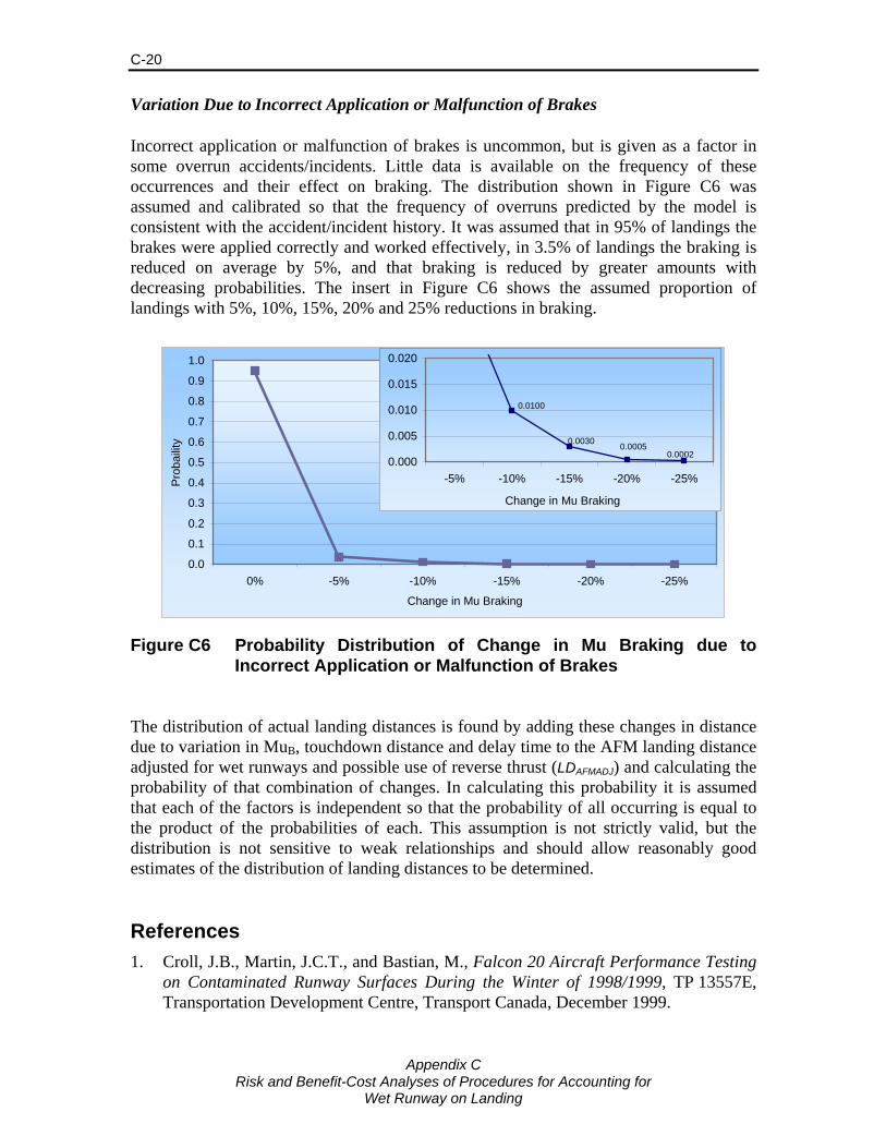
Appendix C
Risk and Benefit-Cost Analyses of Procedures for Accounting for Wet Runway on Landing
C-20
Variation Due to Incorrect Application or Malfunction of Brakes Incorrect application or malfunction of brakes is uncommon, but is given as a factor in some overrun accidents/incidents. Little data is available on the frequency of these occurrences and their effect on braking. The distribution shown in Figure C6 was assumed and calibrated so that the frequency of overruns predicted by the model is consistent with the accident/incident history. It was assumed that in 95% of landings the brakes were applied correctly and worked effectively, in 3.5% of landings the braking is reduced on average by 5%, and that braking is reduced by greater amounts with decreasing probabilities. The insert in Figure C6 shows the assumed proportion of landings with 5%, 10%, 15%, 20% and 25% reductions in braking.
0.0
0.1
0.2
0.3
0.4
0.5
0.6
0.7
0.8
0.9
1.0
0% -5% -10% -15% -20% -25%
Change in Mu Braking
Pro
baili
ty
0.00020.00050.0030
0.0100
0.000
0.005
0.010
0.015
0.020
-5% -10% -15% -20% -25%
Change in Mu Braking
Figure C6 Probability Distribution of Change in Mu Braking due to Incorrect Application or Malfunction of Brakes
The distribution of actual landing distances is found by adding these changes in distance due to variation in MuB, touchdown distance and delay time to the AFM landing distance adjusted for wet runways and possible use of reverse thrust (LDAFMADJ) and calculating the probability of that combination of changes. In calculating this probability it is assumed that each of the factors is independent so that the probability of all occurring is equal to the product of the probabilities of each. This assumption is not strictly valid, but the distribution is not sensitive to weak relationships and should allow reasonably good estimates of the distribution of landing distances to be determined. References 1. Croll, J.B., Martin, J.C.T., and Bastian, M., Falcon 20 Aircraft Performance Testing
on Contaminated Runway Surfaces During the Winter of 1998/1999, TP 13557E, Transportation Development Centre, Transport Canada, December 1999.
Appendix C
Risk and Benefit-Cost Analyses of Procedures for Accounting for Wet Runway on Landing
C-21
2. Croll, J. and Bastian, M., Falcon 20 Aircraft Braking Performance on Wet Concrete Runway Surfaces, Institute for Aerospace Research, Report LTR-FR-207, July 2004.
3. Croll, J. and Bastian, M., Evaluation of Falcon 20 and DHC-8 Series 100 and 400 Turbopropeller Aircraft Safety Margins for Landings on Wet Runway Surfaces, Institute for Aerospace Research, Report LTR-FR-251, September 2006.
4. Martin, J., Results of a Monte Carlo Statistical Analysis of Operational Landing Distances on Dry and Wet Runways for Turbojet Powered Aircraft, Transport Canada Aircraft Certification Flight Test Division, Discussion Paper No. 22, December 2001.
5. Martin, J., Results of a Monte Carlo Statistical Analysis of Operational Landing Distances on Dry and Wet Runways for Turbopropeller Powered Aircraft, Transport Canada Aircraft Certification Flight Test Division, Discussion Paper No. 29, October 2003.
6. Martin, J., Results of a Monte Carlo Statistical Analysis of Operational Landing Distances on Wet High Friction Runways for Turbojet Powered Aircraft, Transport Canada Aircraft Certification Flight Test Division, Discussion Paper No. 24, March 2007.
7. Skillen, G.J.R., Risk – Worked Example on Landing Distance, ESDU Restricted Circulation Paper P571H, Draft copy, November 2007.
8. Yager, T. J., Volger, W. A., and Baldasare, P., Evaluation of Two Transport Aircraft and Several Ground Test Vehicle Friction Measurements Obtained for Various Runway Surface Types and Conditions. NASA Technical Paper 2917, 1990
9. Yager, T. J., Phillips and Horne, W. B., A Comparison of Aircraft and Ground Vehicle Stopping Performance on Dry, Wet, Flooded, Slush, Snow and Ice Covered Runways. NASA TN D-6098, November 1970
10. Biggs, D.C., and Hamilton, G.B.H., Benefit-Cost Analysis of Procedures for Accounting for Runway Friction on Landing, Transport Canada Report TP 14082E, March 2003.
11. Giesman, P., Wet Runway, Physics, Certification, Application, Presentation by Boeing, 2005.
12. Giesman, P., Takeoff/Landing on Wet, Contaminated and Slippery Runways, Presentation by Boeing, January 2005.
13. Giesman, P., and Captain Ratley, J., Landing on Slippery Runways, Presentation by Boeing, 2006.
14. Horne, W., Elements Affecting Runway Traction, Presented at the SEA Transport Committee Meeting, Dallas, April 30-May 2, 1974.
15. Horne, W., Wet Runways, NASA Technical Memorandum TM X-72650, 1975.
16. ALAR Tool Kit, Briefing Note 8.3 – Landing Distances, Nov. 2000.


Risk and Benefit-Cost Analyses of Procedures for Accounting for Wet Runway on Landing
Appendix D
Estimation of Benefits and Costs


Appendix D
Risk and Benefit-Cost Analyses of Procedures for Accounting for Wet Runway on Landing
D-1
Estimation of Benefits and Costs Cost of Off-Loading Cargo The penalty for removing cargo is assumed to depend on the revenue generated by the cargo on the flight segment. In many situations, the cargo could be sent on a later flight or a road feeder service at no penalty. In other cases, the shipments may be subject to delivery guarantees, very time sensitive (e.g.,. replacement machine parts) or could be perishable. Sometimes, the shipments may be extremely urgent. A delayed shipment could then alienate a valuable customer, with a substantial loss of good will and future revenue. Given these variations in the urgency and costs of removing cargo, the average penalty is estimated by: Cost Off-loaded Cargo = WEIGHT x (CONSTANT + CARGOFCST x FLIGHTKM) where CONSTANT represents the handling cost. and CARGOFCST accounts for the transport component of the cost. The average revenue from cargo carried by a sample of air cargo carriers worldwide was around $0.24 per tonne-km in 2005. Costs of carrying air cargo have been declining by 2-3% per year since 2005 and an average yield of $0.23 per tonne-km was used in the analysis. These represent average yield per tonne-km, including handling and aircraft costs, and are weighted heavily towards long distance freight as this makes-up the large majority of tonne-km of cargo. The handling cost is estimated to be $.20 per kilogram and the flight cost $0.20 per tonne-km. The estimated costs per kilogram for offloading cargo and average yields per tonne-km are provided in Table D1. Average yields for the wide-body aircraft are equal to the average industry yields, while the yields (per tonne-km) are higher for the smaller aircraft. Cost of Off-Loading Passengers The cost of unloading passengers was assumed to equal the average one-way fare, excluding taxes and airport charges, for a typical flight distance for the aircraft being off-loaded. The average one-way fare was estimated by: One-way Fare = CONSTANT + FLIGHTKM x PAXFCST where COSTSANT represents the airport charges and fixed costs per passenger, and PAXFCST accounts for the transport component of the cost.

Appendix D
Risk and Benefit-Cost Analyses of Procedures for Accounting for Wet Runway on Landing
D-2
Table D1. Typical Flight Distances, Costs of Off-loading Cargo and Average Yields for Aircraft Analyses
Aircraft Type Avg. Flight Dist. km
Cost for Off-loaded Cargo per kg
Average Yield per tonne-km
CRJ-100/200 955 $0.39 $0.41 E-190 981 $0.40 $0.40 B737-300 1,203 $0.44 $0.37 B737-800 2,856 $0.77 $0.27 B767-200ER 6,080 $1.42 $0.23 B777-200ER 8,352 $1.87 $0.22 B747-400 7,589 $1.72 $0.23 A320-200 1,605 $0.52 $0.32 A330-200 6,577 $1.52 $0.23 A340-300 7,959 $1.79 $0.23 DHC8-100 329 $0.27 $0.81 DHC8-400 359 $0.27 $0.76
Based on an analysis of airfare data, the constant was set to $120 and the flight cost, PAXFCST, to 0.11. The resulting costs for off-loading passengers (i.e., one-way fares) and average yields are given for a range of flight distances in Table D2. Table D2. Costs of Off-loading Passengers and Average Yields for a
Range of Flight Distances
Flight Dist. Cost per Avg. Yield km Passenger* $/km $/mile 200 $142 $0.71 $0.44400 $164 $0.41 $0.25600 $186 $0.31 $0.19800 $208 $0.26 $0.16
1,000 $230 $0.23 $0.142,000 $340 $0.17 $0.113,000 $450 $0.15 $0.094,000 $560 $0.14 $0.0875,000 $670 $0.13 $0.0836,000 $780 $0.13 $0.0817,000 $890 $0.13 $0.0798,000 $1,000 $0.13 $0.078
* Equal to one-way airfare

Appendix D
Risk and Benefit-Cost Analyses of Procedures for Accounting for Wet Runway on Landing
D-3
Cost of Delays En Route The cost of delaying the flight while en route was determined based on the additional aircraft operating costs, the costs of downstream delays and the value of passenger delay time. The relationships used were as follows: VDELAY = OPCOST + PAXCOST + DSTRMCOST where OPCOST Aircraft operating cost PAXCOST Passenger costs DSTRMCOST Downstream cost The aircraft operating costs and passenger costs were found by multiplying the delay time by the appropriate aircraft and passenger costs per hour: OPCOST = DELAY x ACBHCST PAXCOST = DELAY x NSEATS x LF x VTIME where VDELAY Value of the delay DELAY Delay time (hrs) ACBHCOST Total aircraft block hour cost NSEATS Number of passenger seats LF Passenger load factor VTIME Value of time of passengers set to $25 per hr The downstream cost is the least known of the costs, but for long delays it is the greatest component of the costs. Downstream delays were estimated by summing the delay cost for successive flights following the originally delayed flight, assuming that it is possible to make up 20 minutes on each flight. The 20 minutes is typical for most operations. No additional delay costs are added when the flight is the last flight of the day and it is assumed that by the next morning the flights are back on schedule. An average of six flights per day is assumed and the initially delayed flight could be any one of the six flights. The following function was found to give the downstream costs found using this approach (at least approximately): DSTRMCOST = (NSEATS x VTIME + ACBHCST) x (1.83 x (DELAY1.1) – 0.3) Estimation of Overrun Costs As discussed in Section 6.2, the accident severity was estimated as a function of the additional runway required to avoid and accident and the terrain beyond the end of the runway based on data from aircraft overruns. The relationships developed are given below.
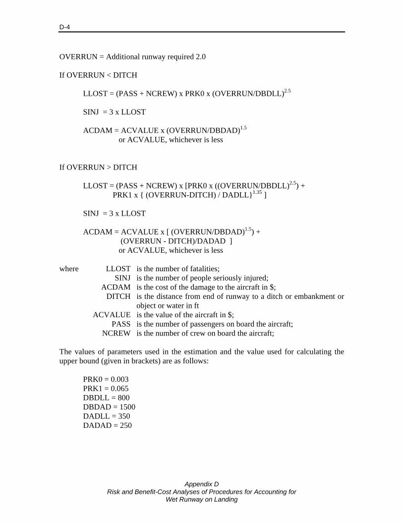
Appendix D
Risk and Benefit-Cost Analyses of Procedures for Accounting for Wet Runway on Landing
D-4
OVERRUN = Additional runway required 2.0 If OVERRUN < DITCH LLOST = (PASS + NCREW) x PRK0 x (OVERRUN/DBDLL)2.5 SINJ = 3 x LLOST ACDAM = ACVALUE x (OVERRUN/DBDAD)1.5 or ACVALUE, whichever is less If OVERRUN > DITCH LLOST = (PASS + NCREW) x [PRK0 x ((OVERRUN/DBDLL)2.5) + PRK1 x { (OVERRUN-DITCH) / DADLL}1.35 ] SINJ = 3 x LLOST ACDAM = ACVALUE x [ (OVERRUN/DBDAD)1.5) + (OVERRUN - DITCH)/DADAD ] or ACVALUE, whichever is less where LLOST is the number of fatalities; SINJ is the number of people seriously injured; ACDAM is the cost of the damage to the aircraft in $; DITCH is the distance from end of runway to a ditch or embankment or
object or water in ft ACVALUE is the value of the aircraft in $; PASS is the number of passengers on board the aircraft; NCREW is the number of crew on board the aircraft; The values of parameters used in the estimation and the value used for calculating the upper bound (given in brackets) are as follows: PRK0 = 0.003 PRK1 = 0.065 DBDLL = 800 DBDAD = 1500 DADLL = 350 DADAD = 250

Risk and Benefit-Cost Analyses of Procedures for Accounting for
Wet Runway on Landing
Appendix E
Section 2 of Economic Values for FAA Investment and Regulatory Decisions, A Guide

DRAFT
SECTION 2: TREATMENT OF THE VALUES OF LIFE AND INJURY IN ECONOMIC ANALYSIS
2.1 APPROACH This section addresses the treatment of the values of life and injury in economic analyses that support regulatory actions or investment decisions by the FAA. It is based on guidance furnished by the Office of the Secretary of Transportation (OST) via memorandum dated January 29, 2002. This guidance provides recommendations to all modal administrators on the treatment of the values of life and injury in economic analyses. It specifies that values of life and injury be based on the “willingness to pay” (WTP) by society for reduced risks of fatalities and injuries.7 WTP is the theoretically correct approach to valuing all benefits arising from public investments or regulatory actions including fatalities and injuries avoided as a result of aviation accident risk reduction. WTP values the risk of injury or loss of life because it is the maximum value of other goods and services that individuals would be willing to forgo and still be as well off after the introduction of an accident risk reduction as they were before it. The basic approach taken to value an avoided fatality is to determine how much an individual or group of individuals is willing to pay for a small reduction in risk. Once this amount is known, it is necessary to determine how much risk reduction is required to avoid one fatality. The total willingness to pay for the amount of risk reduction required to avoid one fatality is termed the value of life or sometimes the value of a statistical life.8 For example, if people are willing to pay $3 to eliminate an incremental risk of a fatality with a one in one million chance of occurrence, this implies that they would be willing as a group to pay $3 million to prevent one fatality. From another perspective, $3 million represents the amount a group as a whole would be willing to pay to purchase the risk reduction necessary to avoid one expected fatality among its members.
7 “Revised Departmental Guidance—Treatment of Value of Life and Injuries in Preparing Economic Evaluations,” Office of the Secretary of Transportation Memorandum, January 29, 2002. This memorandum establishes the specific value of life to be used in all DOT analyses. The original guidance establishing willingness to pay as the appropriate type of measure is contained in an OST memorandum dated January 8, 1993. 8 The terms value of life and value of statistical life are misleading at best in that they refer to the sum of payments associated with many small fatality risk reductions undertaken prior to the occurrence of a fatality. They have no application to placing a value on the death of any specific individual.
Treatment of the Values of Life and Injury in Economic Analysis 2-1

DRAFT
In theory, the same approach (assessing the willingness to pay to avoid various kinds of injury) could be used to value injuries. However, in practice it cannot currently be done because of data limitations. As will be indicated below, an alternative approach is used which values avoided injuries as a fraction of an avoided fatality. 2.2 VALUE OF LIFE For the analysis conducted in 1993, OST guidance suggested that $2.5 million be used as the minimum value of a statistical fatality avoided. This value was based upon a survey of studies performed by Ted Miller and others at the Urban Institute, adjusted to 1993 dollars.9 The guidance also provided that OST would update this value early each year using the Gross Domestic Product implicit price deflator. Subsequently, OST updated the value of life for analyses to be conducted in 1994 to $2.6 million per fatality averted10 and in 1995 and 1996 to $2.7 million.11 The latest OST guidance establishes a minimum value of $3 million per fatality averted. This $3 million value (and the injury values based on it presented below) should be used in all FAA analyses until revised by OST.12
In addition, some recent studies have examined the value per fatality avoided, including a meta-analysis by Ted Miller and similar studies by Viscusi and Aldy and Mrozek and Taylor.13 These provide information on the range of values used in other applications. 2.3 VALUE OF INJURIES The January 8, 1993 OST guidance also established a procedure for valuing averted injuries based on the current value of life and the Abbreviated Injury Scale (AIS). AIS is a comprehensive system for rating the severity of accident-related injuries that recognizes six levels of injury severity. It classifies nonfatal injuries into five
9 Ted R. Miller et al., The Costs of Highway Crashes, (Washington, DC: Urban Institute, 1991). 10 “Update of Value of Life and Injuries for Use in Preparing Economic Evaluations,” Department of Transportation Memorandum, March 15, 1994. 11 “Update of Value of Life and Injuries for Use in Preparing Economic Evaluations,” Department of Transportation Memorandum, March 14, 1995, and “Update of Value of Life and Injuries for Use in Preparing Economic Evaluations,” Department of Transportation Memorandum, 1996. 12“Revised Departmental Guidance, Treatment of Value of Life and Injuries in Preparing Economic Evaluations,” Office of the Secretary of Transportation Memorandum, January 29, 2002. 13 Ted R. Miller, “Variations between Countries in Values of Statistical Life,” Journal of Transport Economics and Policy Vol. 34 (May 2000): 169-188; W. Kip Viscusi and JosephE. Aldy, The Value of Statistical Life: A Critical Review of Market Estimates Throughout the World, National Bureau of Economic Research, February 2003, Working Paper 9487; Janusz R. Mrozek and Laura O. Taylor, “What Determines the Value of Life? A Meta-Analysis”, Journal of Policy Analysis and Management Vol.21 (2002): 253-270.
2-2 Treatment of the Values of Life and Injury in Economic Analysis
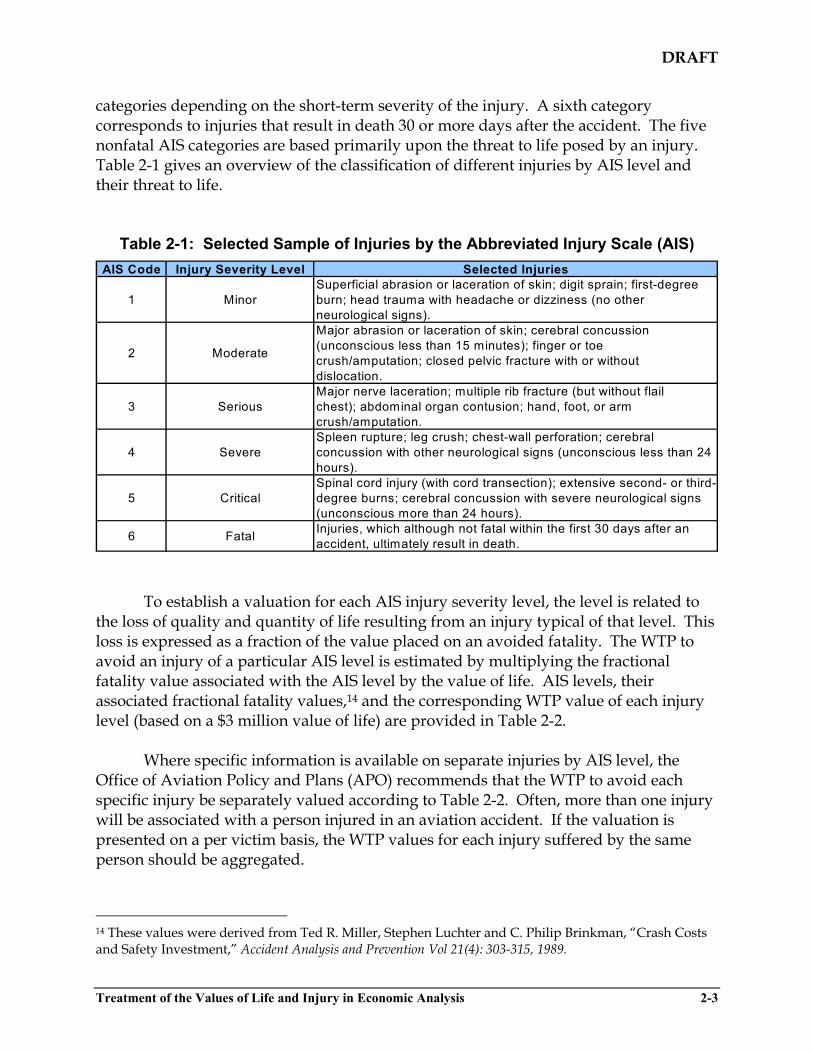
DRAFT
categories depending on the short-term severity of the injury. A sixth category corresponds to injuries that result in death 30 or more days after the accident. The five nonfatal AIS categories are based primarily upon the threat to life posed by an injury. Table 2-1 gives an overview of the classification of different injuries by AIS level and their threat to life.
Table 2-1: Selected Sample of Injuries by the Abbreviated Injury Scale (AIS) AIS Code Injury Severity Level Selected Injuries
1 MinorSuperficial abrasion or laceration of skin; digit sprain; first-degree burn; head trauma with headache or dizziness (no other neurological signs).
2 Moderate
Major abrasion or laceration of skin; cerebral concussion (unconscious less than 15 minutes); finger or toecrush/amputation; closed pelvic fracture with or withoutdislocation.
3 SeriousMajor nerve laceration; multiple rib fracture (but without flailchest); abdominal organ contusion; hand, foot, or arm crush/amputation.
4 SevereSpleen rupture; leg crush; chest-wall perforation; cerebral concussion with other neurological signs (unconscious less than 24 hours).
5 CriticalSpinal cord injury (with cord transection); extensive second- or third-degree burns; cerebral concussion with severe neurological signs (unconscious more than 24 hours).
6 Fatal Injuries, which although not fatal within the first 30 days after an accident, ultimately result in death.
To establish a valuation for each AIS injury severity level, the level is related to the loss of quality and quantity of life resulting from an injury typical of that level. This loss is expressed as a fraction of the value placed on an avoided fatality. The WTP to avoid an injury of a particular AIS level is estimated by multiplying the fractional fatality value associated with the AIS level by the value of life. AIS levels, their associated fractional fatality values,14 and the corresponding WTP value of each injury level (based on a $3 million value of life) are provided in Table 2-2. Where specific information is available on separate injuries by AIS level, the Office of Aviation Policy and Plans (APO) recommends that the WTP to avoid each specific injury be separately valued according to Table 2-2. Often, more than one injury will be associated with a person injured in an aviation accident. If the valuation is presented on a per victim basis, the WTP values for each injury suffered by the same person should be aggregated.
14 These values were derived from Ted R. Miller, Stephen Luchter and C. Philip Brinkman, “Crash Costs and Safety Investment,” Accident Analysis and Prevention Vol 21(4): 303-315, 1989.
Treatment of the Values of Life and Injury in Economic Analysis 2-3

DRAFT
Table 2-2: WTP Values Per AIS Injury Level (2001 dollars)
AIS Code Descriptionof Injury
Fraction of WTPValue of Life WTP Value
AIS 1 Minor 0.20% $6,000 AIS 2 Moderate 1.55% $46,500 AIS 3 Serious 5.75% $172,500 AIS 4 Severe 18.75% $562,500 AIS 5 Critical 76.25% $2,287,500 AIS 6 Fatal 100.00% $3,000,000
2.4 OTHER COSTS Costs other than WTP values are generally associated with transportation fatalities and injuries. These include the costs of emergency services, medical care, and legal and court services (the cost of carrying out court proceedings—not the cost of settlements). These other avoided costs should be considered as separate benefits, additional to the WTP value. Because medical and legal costs of separate injuries to the same victim are not necessarily additive, APO advises that medical and legal costs be valued on a per victim basis. Table 2-3 provides direct per victim medical and legal costs classified according to the worst AIS injury sustained by each aviation accident victim. Thus, the values in Table 2-3 should be added only once to the aggregated sum of the WTP values for injuries suffered by any particular individual.15
Table 2-3: Per Victim Medical and Legal Costs Associated with Injuries (2001 dollars)
Total Direct Costs
AIS 1 Minor $600 $1,900 AIS 2 Moderate $4,000 $3,100 $7,100 AIS 3 Serious $16,500 $4,700 $21,200 AIS 4 Severe $72,500 $39,100 $111,600 AIS 5 Critical $219,900 $80,100 $300,000 AIS 6 Fatal $52,600 $80,100 $132,700
Source: Economic Values for Evaluation of Federal Aviation Administration Investment and Regulatory Programs, FAA-APO-89-10, October 1989, Section 3, as adjusted for price level changes.
AIS Code Description of Maximum Injury
Emergency/ Medical Legal/Court
$2,500
15 Similar direct costs apply in the case of fatalities. However, APO estimates that these direct costs are less than $50,000 per fatality--not enough to shift the $3 million WTP value after allowances for the rounding convention--to the nearest $100,000--used by OST.
2-4 Treatment of the Values of Life and Injury in Economic Analysis
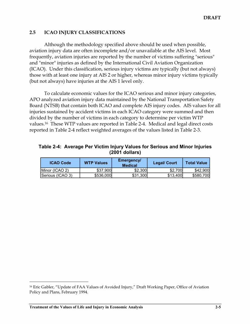
DRAFT
2.5 ICAO INJURY CLASSIFICATIONS Although the methodology specified above should be used when possible, aviation injury data are often incomplete and/or unavailable at the AIS level. Most frequently, aviation injuries are reported by the number of victims suffering "serious" and "minor" injuries as defined by the International Civil Aviation Organization (ICAO). Under this classification, serious injury victims are typically (but not always) those with at least one injury at AIS 2 or higher, whereas minor injury victims typically (but not always) have injuries at the AIS 1 level only.
To calculate economic values for the ICAO serious and minor injury categories, APO analyzed aviation injury data maintained by the National Transportation Safety Board (NTSB) that contain both ICAO and complete AIS injury codes. AIS values for all injuries sustained by accident victims in each ICAO category were summed and then divided by the number of victims in each category to determine per victim WTP values.16 These WTP values are reported in Table 2-4. Medical and legal direct costs reported in Table 2-4 reflect weighted averages of the values listed in Table 2-3.
Table 2-4: Average Per Victim Injury Values for Serious and Minor Injuries
(2001 dollars)
ICAO Code WTP Values Emergency/ Medical Legal/ Court Total Value
Minor (ICAO 2) $37,900 $2,300 $2,700 $42,900 Serious (ICAO 3) $536,000 $31,300 $13,400 $580,700
16 Eric Gabler, “Update of FAA Values of Avoided Injury,” Draft Working Paper, Office of Aviation Policy and Plans, February 1994.
Treatment of the Values of Life and Injury in Economic Analysis 2-5

Risk and Benefit-Cost Analyses of Procedures for Accounting for Wet Runway on Landing
Appendix F
Results of Benefit-Cost Analyses

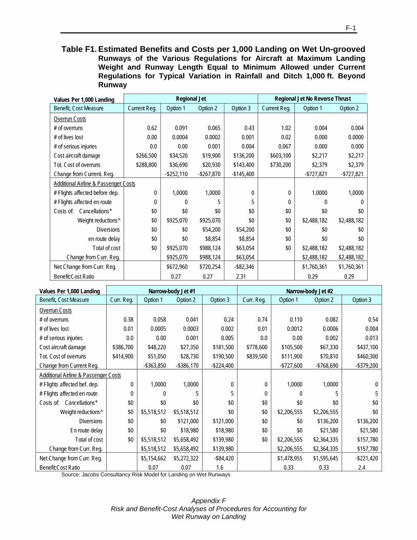
F-1
Appendix F
Risk and Benefit-Cost Analyses of Procedures for Accounting for Wet Runway on Landing
Table F1. Estimated Benefits and Costs per 1,000 Landing on Wet Un-grooved Runways of the Various Regulations for Aircraft at Maximum Landing Weight and Runway Length Equal to Minimum Allowed under Current Regulations for Typical Variation in Rainfall and Ditch 1,000 ft. Beyond Runway
Values Per 1,000 Landing Regional Jet Regional Jet No Reverse Thrust Benefit, Cost Measure Current Reg. Option 1 Option 2 Option 3 Current Reg. Option 1 Option 2 Overrun Costs # of overruns 0.62 0.091 0.065 0.43 1.02 0.004 0.004 # of lives lost 0.00 0.0004 0.0002 0.001 0.02 0.000 0.0000 # of serious injuries 0.0 0.00 0.001 0.004 0.067 0.000 0.000 Cost aircraft damage $266,500 $34,520 $19,900 $136,200 $603,100 $2,217 $2,217 Tot. Cost of overruns $288,800 $36,690 $20,930 $143,400 $730,200 $2,379 $2,379 Change from Current. Reg. -$252,110 -$267,870 -$145,400 -$727,821 -$727,821 Additional Airline & Passenger Costs # Flights affected before dep. 0 1,0000 1,0000 0 0 1,0000 1,0000 # Flights affected en route 0 0 5 5 0 0 0 Costs of: Cancellations* $0 $0 $0 $0 $0 $0 $0
Weight reductions^ $0 $925,070 $925,070 $0 $0 $2,488,182 $2,488,182 Diversions $0 $0 $54,200 $54,200 $0 $0 $0
en route delay $0 $0 $8,854 $8,854 $0 $0 $0 Total of cost $0 $925,070 $988,124 $63,054 $0 $2,488,182 $2,488,182
Change from Curr. Reg. $925,070 $988,124 $63,054 $2,488,182 $2,488,182 Net Change from Curr. Reg. $672,960 $720,254 -$82,346 $1,760,361 $1,760,361 Benefit:Cost Ratio 0.27 0.27 2.31 0.29 0.29
Values Per 1,000 Landing Narrow-body Jet #1 Narrow-body Jet #2 Benefit, Cost Measure Curr. Reg. Option 1 Option 2 Option 3 Curr. Reg. Option 1 Option 2 Option 3 Overrun Costs # of overruns 0.38 0.058 0.041 0.24 0.74 0.110 0.082 0.54 # of lives lost 0.01 0.0005 0.0003 0.002 0.01 0.0012 0.0006 0.004 # of serious injuries 0.0 0.00 0.001 0.005 0.0 0.00 0.002 0.013 Cost aircraft damage $386,700 $48,220 $27,350 $181,500 $778,600 $105,500 $67,330 $437,100 Tot. Cost of overruns $414,900 $51,050 $28,730 $190,500 $839,500 $111,900 $70,810 $460,300 Change from Current Reg. -$363,850 -$386,170 -$224,400 -$727,600 -$768,690 -$379,200 Additional Airline & Passenger Costs # Flights affected bef. dep. 0 1,0000 1,0000 0 0 1,0000 1,0000 0 # Flights affected en route 0 0 5 5 0 0 5 5 Costs of: Cancellations* $0 $0 $0 $0 $0 $0 $0 $0
Weight reductions^ $0 $5,518,512 $5,518,512 $0 $0 $2,206,555 $2,206,555 $0 Diversions $0 $0 $121,000 $121,000 $0 $0 $136,200 $136,200
En route delay $0 $0 $18,980 $18,980 $0 $0 $21,580 $21,580 Total of cost $0 $5,518,512 $5,658,492 $139,980 $0 $2,206,555 $2,364,335 $157,780
Change from Curr. Reg. $5,518,512 $5,658,492 $139,980 $2,206,555 $2,364,335 $157,780 Net Change from Curr. Reg. $5,154,662 $5,272,322 -$84,420 $1,478,955 $1,595,645 -$221,420 Benefit:Cost Ratio 0.07 0.07 1.6 0.33 0.33 2.4
Source: Jacobs Consultancy Risk Model for Landing on Wet Runways

F-2
Appendix F
Risk and Benefit-Cost Analyses of Procedures for Accounting for Wet Runway on Landing
Values Per 1,000 Landing Wide-body Jet #1 Wide-body Jet #2 Benefit, Cost Measure Curr. Reg. Option 1 Option 2 Option 3 Curr. Reg. Option 1 Option 2 Option 3 Overrun Costs # of overruns 0.50 0.069 0.044 0.32 0.24 0.035 0.002 0.05 # of lives lost 0.01 0.0011 0.0004 0.003 0.08 0.0066 0.0000 0.001 # of serious injuries 0.0 0.00 0.001 0.009 0.2 0.02 0.000 0.002 Cost aircraft damage $650,000 $79,100 $38,160 $283,000 $1,847,000 $248,300 $6,044 $106,700 Tot. Cost of overruns $716,200 $84,940 $40,360 $299,200 $2,265,000 $284,500 $6,284 $110,300 Change from Current Reg. -$631,260 -$675,840 -$417,000 -$1,980,500 -$2,258,716 -$2,154,700 Additional Airline & Passenger Costs # Flights affected bef. dep. 0 1,0000 1,0000 0 0 1,0000 1,0000 0 # Flights affected en route 0 0 5 5 0 0 5 5 Costs of: Cancellations* $0 $0 $0 $0 $0 $0 $0 $0
Weight reductions^ $0 $18,176,335 $18,176,335 $0 $0 $33,621,832 $33,621,832 $0 Diversions $0 $0 $192,800 $192,800 $0 $0 $289,000 $289,000
En route delay $0 $0 $30,290 $30,290 $0 $0 $45,300 $45,300 Total of cost $0 $18,176,335 $18,399,425 $223,090 $0 $33,621,832 $33,956,132 $334,300
Change from Curr. Reg. $18,176,335 $18,399,425 $223,090 $33,621,832 $33,956,132 $334,300 Net Change from Curr. Reg. $17,545,075 $17,723,585 -$193,910 $31,641,332 $31,697,416 -$1,820,400 Benefit:Cost Ratio 0.03 0.04 1.9 0.06 0.07 6.4
Source: Jacobs Consultancy Risk Model for Landing on Wet Runways
Large Turboprop #1 Large Turboprop #2 Benefit, Cost Measure Curr. Reg. Option 1 Option 2 Option 3 Curr. Reg. Option 1 Option 2 Option 3 Overrun Costs # of overruns 1.37 0.067 0.060 0.94 4.32 0.110 0.040 3.31 # of lives lost 0.00 0.0000 0.0000 0.001 0.04 0.0008 0.0001 0.006 # of serious injuries 0.0 0.00 0.000 0.002 0.1 0.00 0.000 0.019 Cost aircraft damage $94,200 $3,857 $3,425 $51,980 $1,553,000 $48,130 $9,489 $681,300 Tot. Cost of overruns $100,400 $4,087 $3,631 $55,040 $1,749,000 $52,560 $10,060 $715,600 Change from Current Reg. -$96,313 -$96,769 -$45,360 -$1,696,440 -$1,738,940 -$1,033,400 Additional Airline & Passenger Costs # Flights affected bef. dep. 0 1,0000 1,0000 0 0 1,0000 1,0000 0 # Flights affected en route 0 0 5 5 0 0 5 5 Costs of: Cancellations* $0 $0 $0 $0 $0 $0 $0 $0
Weight reductions^ $0 $576,581 $576,581 $0 $0 $1,025,190 $1,025,190 $0 Diversions $0 $0 $45,810 $45,810 $0 $0 $77,790 $77,790
En route delay $0 $0 $7,711 $7,711 $0 $0 $12,770 $12,770 Total of cost $0 $576,581 $630,102 $53,521 $0 $1,025,190 $1,115,750 $90,560
Change from Curr. Reg. $576,581 $630,102 $53,521 $1,025,190 $1,115,750 $90,560 Net Change from Curr. Reg. $480,268 $533,333 $8,161 -$671,250 -$623,190 -$942,840 Benefit:Cost Ratio 0.17 0.15 0.8 1.65 1.56 11.4
Source: Jacobs Consultancy Risk Model for Landing on Wet Runways

Risk and Benefit-Cost Analyses of Procedures for Accounting for Wet Runway on Landing
Appendix G
Procedures and Experience with Grooved Runways

Appendix G
Risk and Benefit-Cost Analyses of Procedures for Accounting for Wet Runway on Landing
G-1
Procedures and Experience with Grooved Runways Information on grooving of runways in the US was drawn from published reports, FAA regulations and Advisory Circulars (ACs), and non-proprietary industry data. FAA AC [18] contains guidelines and procedures for grooving runways. Although the AC does not mandate grooving, it has been accepted as the norm for all runways in the U.S. that serve turbojet aircraft. The AC states that if a runway-grooving project is funded through a Federal grant assistance program, AC paragraphs 2-21 and 2-22 must be followed. The groove geometry and spacing is ¼ in. by ¼ in. spaced 1 ½ in. on center or 6 mm by 6 mm spaced 38 mm on center. Costs for runway grinding may be separated still into fixed and variable costs. The FAA on-line Technical Specification Manual includes the following variable costs that echo earlier FAA report [47, 48]:
Cost of blades – dependent on the hardness of pavement
Labor costs – dependent on prevailing wage rates
Number of hours of uninterrupted work – dependent on runway availability. Another variable cost that must be considered involve the disposal of waste material. On-site versus off-site disposal can have significant cost impacts. Cardinal International Grooving and Grinding Inc. [49] published estimates of runway grooving (in 2006 US$) that range from US$0.50 to over US$3.00 per square yard or US$0.62 to US$3.57 per square meter. A higher cost of 3 Euros per square meter (approximately $4.50 and US$4.50) was reported to groove the two concrete runways at Munich Airport [50]. Maintenance costs for grooved runways beyond that necessary for non-grooved pavements are difficult to accurately quantify. The ubiquitous nature of grooved runways in the U.S. does not afford an appropriate or reliable basis for comparison with a non-grooved runway in a similar setting Information regarding the need for additional sweeping, clearing, chemicals or abrasives due to the presence of grooves could not be identified from published FAA and industry sources. Nor were any reports or documentation found that indicated groove degradation due to winter maintenance procedures. In fact, FAA Advisory Circular [51] supports an opposing view: “Grooves cut into the pavement will trap anti-icing/deicing chemicals, reduce loss, and prolong their actions. Grooves also assist in draining melt water and preventing refreezing. There is empirical evidence that grooves and porous friction courses modify the thermal characteristics of a pavement surface, probably by reducing the radiant heat loss, and delay the formation of ice. There do not appear to be any negative effects from grooving pavements.” The following effects on winter servicing of the runways following grooving were reported by the Munich Airport [50]:
Appendix G
Risk and Benefit-Cost Analyses of Procedures for Accounting for Wet Runway on Landing
G-2
During heavy rainfall the grooves conduct the surface water away immediately;
No general improvement was noticeable with snow on the runway;
No winter service call outs were necessary in the case of small amounts of rainfall or hoarfrost because of less freezing over;
Sweeper blowers are able to remove snow and ice from the grooves; and
Quantity of thawing applied had to be increased in heavy snowfall and the event of freezing rain.
No information could be found in any published reports regarding the need for additional maintenance during non-winter operations due to the presence of grooves in the US. However, Munich Airport reported [50] that:
Grooving has resulted in lower rubber abrasion;
The requirement to conduct rubber removal was reduced by a factor of two, from 5-6 times per summer season before the runways were grooved to only twice per summer after grooving; and
Removal of rubber is not more difficult with the grooves and there is no damage to the grooves from the rubber removal.
Grooves can deteriorate over time. FAA AC [18, paragraph 3.5] states that: “When 40 percent of the grooves in the runway are equal to or less than 1/8 in. (3 mm) in depth and/or width for a distance of 1,500 ft. (457 m), the grooves’ effectiveness for preventing hydroplaning has been considerably reduced. The airport operator should take immediate corrective action to reinstate the 1/4 in. (6 mm) groove depth and/or width.” Hot Mix Asphalt (HMA) or asphaltic concrete surfaces are susceptible to shoving or closure of the grooves, especially in touchdown and hard-braking areas. The durability or effective life cycle of these grooves is a function of the stability of the pavement. The grooves in asphalt runways typically require re-grooving every six to eight years while concrete pavement holds the grooves throughout the lifecycle of the pavement (20-50 years) [52]. The corrective action for serious groove deterioration is to overlay the runway surface and then re-groove. Re-grooving costs are no different that grooving an original surface.


