RIPP LOCK screw lock - media.boellhoff.com · 22 The system Working-principle RIPP LOCK® lock...
16
Efficient and secure 8210/16.02 RIPP LOCK ® screw lock
Transcript of RIPP LOCK screw lock - media.boellhoff.com · 22 The system Working-principle RIPP LOCK® lock...
Efficient and secure
8210/16.02
RIPP LOCK® screw lock
22
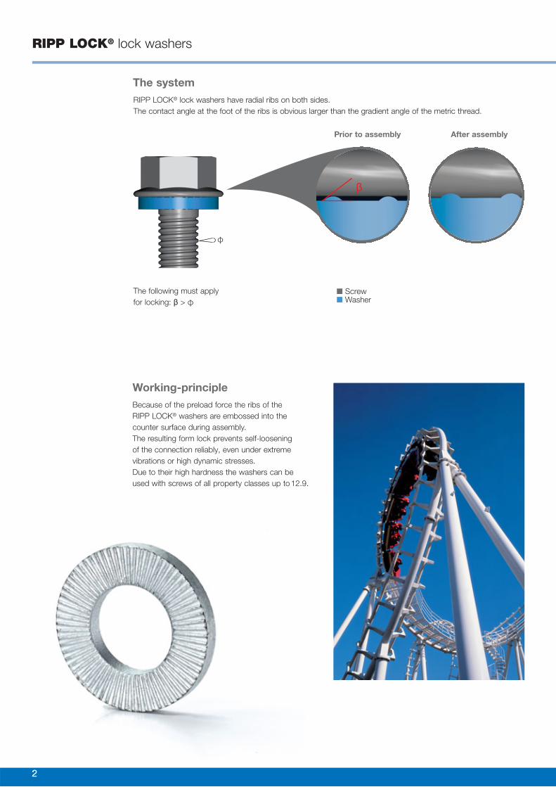
The system
Working-principle
RIPP LOCK® lock washers have radial ribs on both sides.The contact angle at the foot of the ribs is obvious larger than the gradient angle of the metric thread.
Because of the preload force the ribs of the RIPP LOCK® washers are embossed into the counter surface during assembly.The resulting form lock prevents self-loosening of the connection reliably, even under extreme vibrations or high dynamic stresses.Due to their high hardness the washers can be used with screws of all property classes up to12.9.
The following must applyfor locking: β > φ
RIPP LOCK® lock washers
φ
Prior to assembly
n Screwn Washer
β
After assembly
33
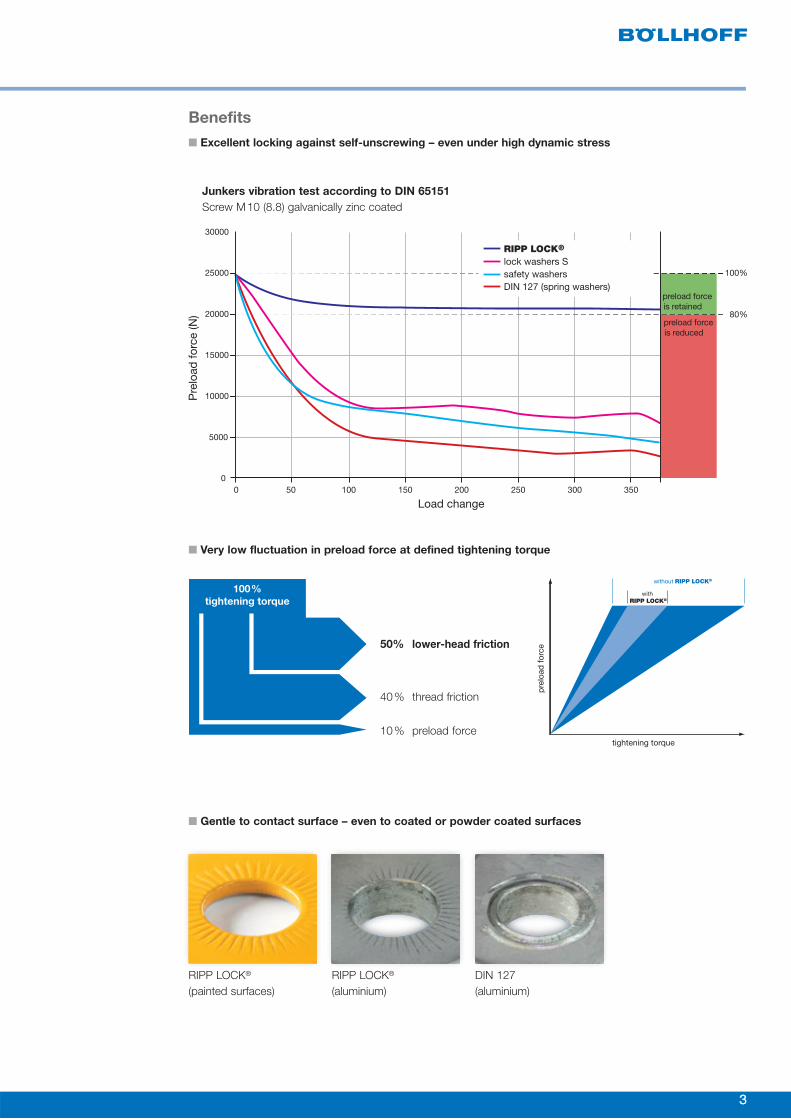
n Excellent locking against self-unscrewing – even under high dynamic stress
0
5000
10000
15000
20000
25000
30000
0 50 100 150 200 250 300 350
80%
100%
Load change
RIPP LOCK®
lock washers S
safety washers
DIN 127 (spring washers) preload force
is retained
preload force
is reduced
Pre
load
fo
rce (N
)Junkers vibration test according to DIN 65151Screw M10 (8.8) galvanically zinc coated
n Gentle to contact surface – even to coated or powder coated surfaces
RIPP LOCK®
(aluminium)RIPP LOCK®
(painted surfaces)DIN 127(aluminium)
n Very low fluctuation in preload force at defined tightening torque
100%tightening torque
with
RIPP LOCK®
without RIPP LOCK®
tightening torque
pre
load
fo
rce50% lower-head friction
40% thread friction
10% preload force
Benefits
44
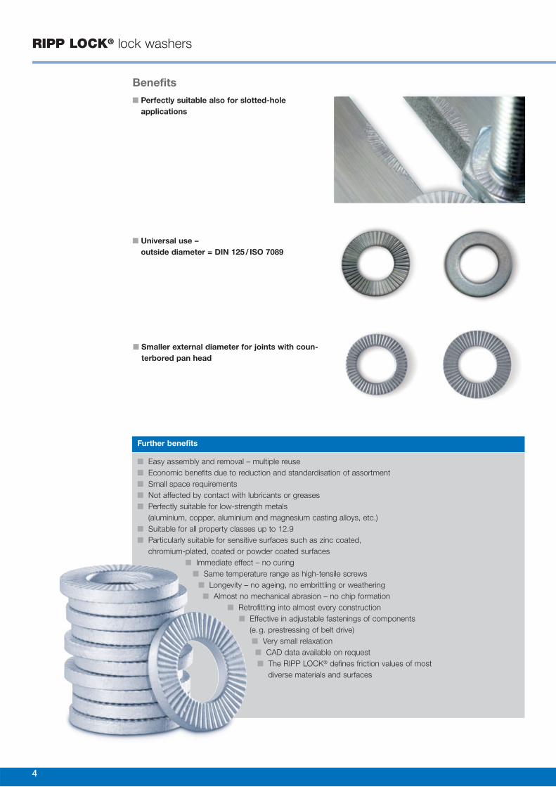
Benefits
n Universal use – outside diameter = DIN 125 / ISO 7089
n Smaller external diameter for joints with coun-terbored pan head
RIPP LOCK® lock washers
Further benefits
n Easy assembly and removal – multiple reusen Economic benefits due to reduction and standardisation of assortmentn Small space requirementsn Not affected by contact with lubricants or greasesn Perfectly suitable for low-strength metals
(aluminium, copper, aluminium and magnesium casting alloys, etc.)n Suitable for all property classes up to 12.9n Particularly suitable for sensitive surfaces such as zinc coated,
chromium-plated, coated or powder coated surfacesn Immediate effect – no curingn Same temperature range as high-tensile screwsn Longevity – no ageing, no embrittling or weatheringn Almost no mechanical abrasion – no chip formation
n Retrofitting into almost every constructionn Effective in adjustable fastenings of components
(e. g. prestressing of belt drive)n Very small relaxationn CAD data available on requestn The RIPP LOCK® defines friction values of most
diverse materials and surfaces
n Perfectly suitable also for slotted-hole applications
55
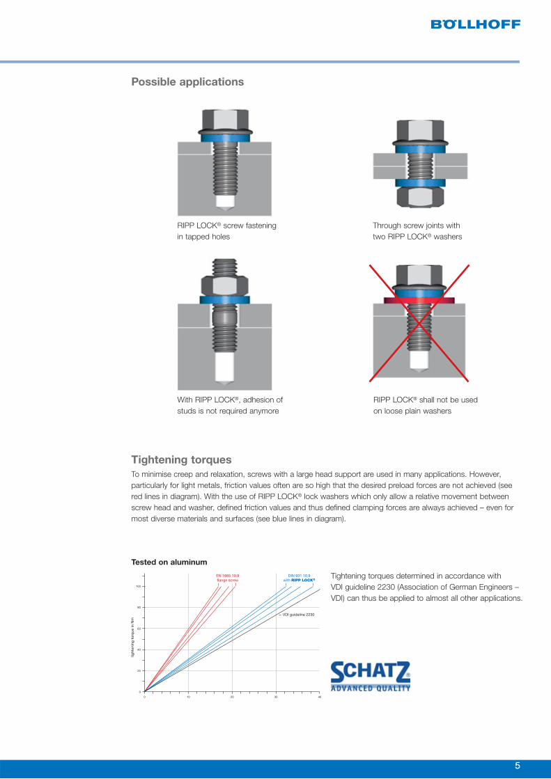
Possible applications
RIPP LOCK® shall not be used on loose plain washers
RIPP LOCK® screw fastening in tapped holes
Through screw joints with two RIPP LOCK® washers
With RIPP LOCK®, adhesion of studs is not required anymore
Tightening torquesTo minimise creep and relaxation, screws with a large head support are used in many applications. However, particularly for light metals, friction values often are so high that the desired preload forces are not achieved (seered lines in diagram). With the use of RIPP LOCK® lock washers which only allow a relative movement betweenscrew head and washer, defined friction values and thus defined clamping forces are always achieved – even formost diverse materials and surfaces (see blue lines in diagram).
0
20
40
60
80
100
0 10 20 30 40
tig
hte
nin
g t
orq
ue in
Nm
EN 1665 10.9
flange screw
DIN 931 10.9
with RIPP LOCK®
VDI guideline 2230
Tested on aluminum
Tightening torques determined in accordance with VDI guideline 2230 (Association of German Engineers –VDI) can thus be applied to almost all other applications.
66
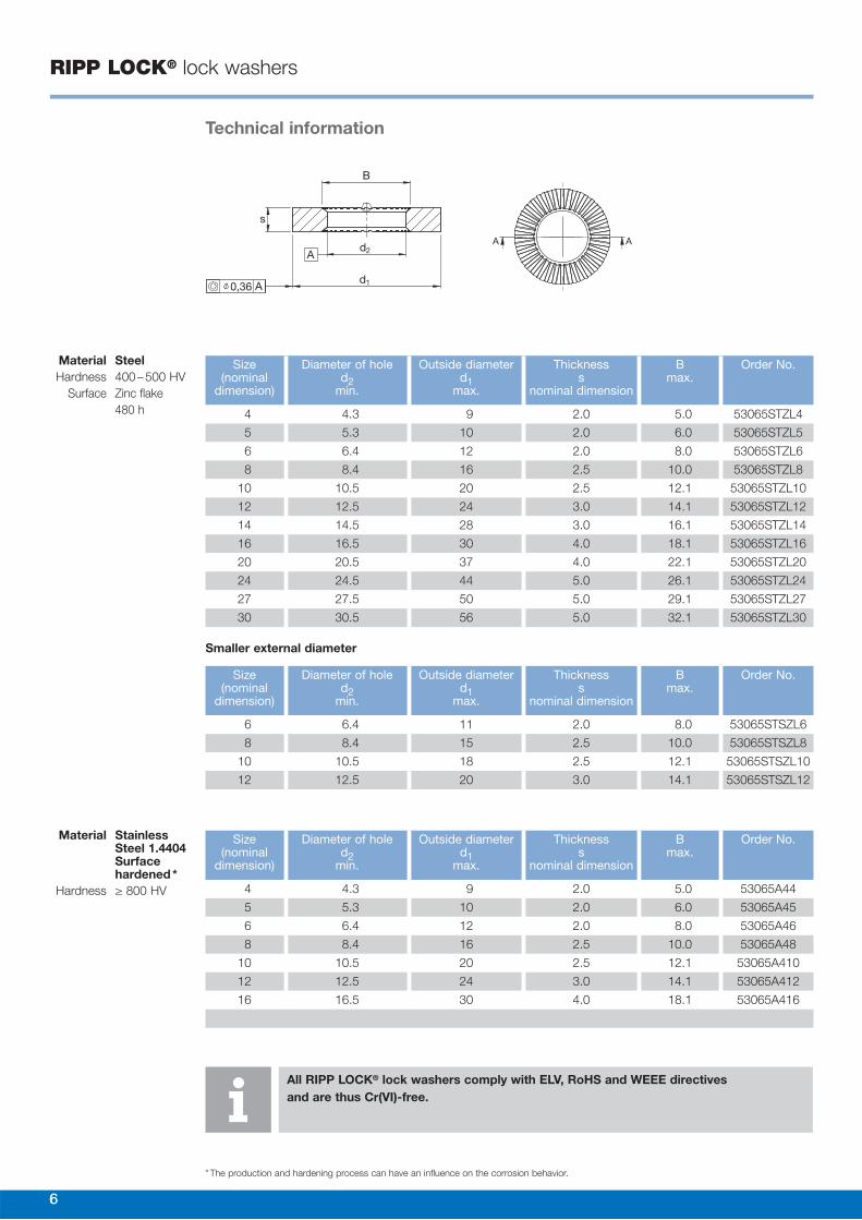
Technical information
B
d2
d1
A
s
A0,36
A A
Material SteelHardness 400– 500 HV
Surface Zinc flake480 h
Smaller external diameter
Material Stainless Steel 1.4404Surface hardened*
Hardness ≥ 800 HV
RIPP LOCK® lock washers
All RIPP LOCK® lock washers comply with ELV, RoHS and WEEE directives and are thus Cr(VI)-free.
* The production and hardening process can have an influence on the corrosion behavior.
Size(nominal
dimension)
Diameter of holed2
min.
Outside diameterd1
max.
Thicknesss
nominal dimension
Bmax.
Order No.
4 4.3 9 2.0 5.0 53065STZL45 5.3 10 2.0 6.0 53065STZL56 6.4 12 2.0 8.0 53065STZL68 8.4 16 2.5 10.0 53065STZL8
10 10.5 20 2.5 12.1 53065STZL1012 12.5 24 3.0 14.1 53065STZL1214 14.5 28 3.0 16.1 53065STZL1416 16.5 30 4.0 18.1 53065STZL1620 20.5 37 4.0 22.1 53065STZL2024 24.5 44 5.0 26.1 53065STZL2427 27.5 50 5.0 29.1 53065STZL2730 30.5 56 5.0 32.1 53065STZL30
Size(nominal
dimension)
Diameter of holed2
min.
Outside diameterd1
max.
Thicknesss
nominal dimension
Bmax.
Order No.
4 4.3 9 2.0 5.0 53065A445 5.3 10 2.0 6.0 53065A456 6.4 12 2.0 8.0 53065A468 8.4 16 2.5 10.0 53065A48
10 10.5 20 2.5 12.1 53065A41012 12.5 24 3.0 14.1 53065A41216 16.5 30 4.0 18.1 53065A416
Size(nominal
dimension)
Diameter of holed2
min.
Outside diameterd1
max.
Thicknesss
nominal dimension
Bmax.
Order No.
6 6.4 11 2.0 8.0 53065STSZL68 8.4 15 2.5 10.0 53065STSZL8
10 10.5 18 2.5 12.1 53065STSZL1012 12.5 20 3.0 14.1 53065STSZL12
Tightening: formation of indentations
Releasing: slight indentations
After release:slightly indented surface
77
RIPP LOCK® lock screws and nuts
Because the ribs do not dig into the surface in therelease direction, the fastening is gentle to sensitivesurfaces.The damage to the surface around the contact area isminimal.
The diagram shows the principle of operation of theseself-locking screws and nuts.
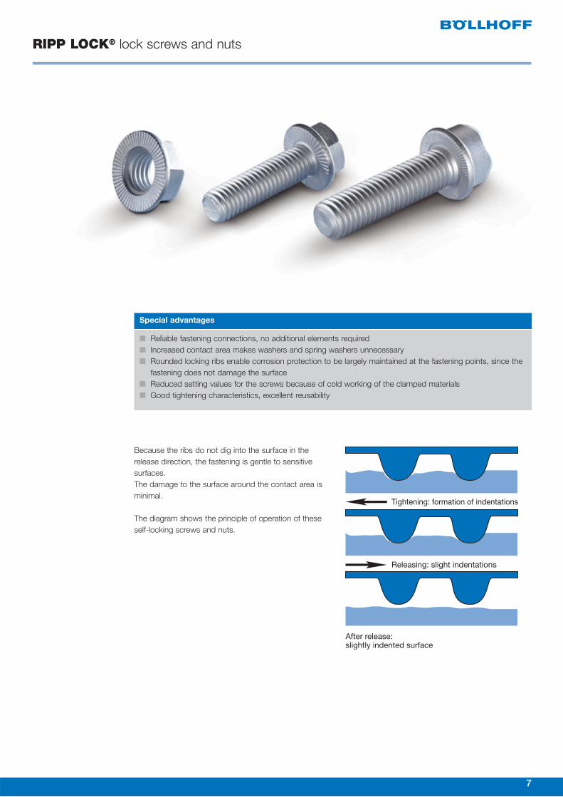
Special advantages
n Reliable fastening connections, no additional elements requiredn Increased contact area makes washers and spring washers unnecessaryn Rounded locking ribs enable corrosion protection to be largely maintained at the fastening points, since the
fastening does not damage the surfacen Reduced setting values for the screws because of cold working of the clamped materialsn Good tightening characteristics, excellent reusability
8
Design instructionsRIPP LOCK® self-locking screws and nuts are available as:n Hexagon socket self-locking screws, property class 100n Hexagon head self-locking screws, property class 100n Hexagon head self-locking nuts, property class 10
For self-locking screws with hexagon socket heads, the head heights and hexagon sizes are identical to those for DIN 912 screws. To achieve a greater contact area the head diameter is slightly increased. This results in areduced surface pressure.
Property classesn Self-locking screws 100 = 1,040 N/mm2
n Self-locking nuts 10: for screws up to property class 10.9 and screw class 100
n Property classes 12.9 and 12 available on request
Hardnessn Hardness at the edge amounts 400 – 500 HV
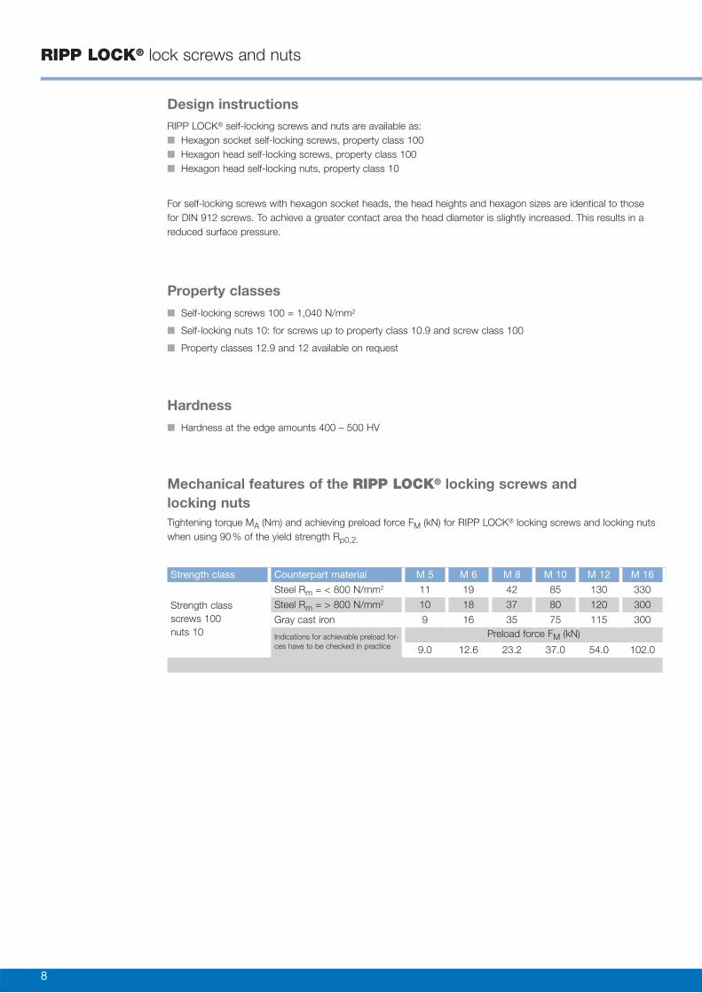
Mechanical features of the RIPP LOCK® locking screws and locking nutsTightening torque MA (Nm) and achieving preload force FM (kN) for RIPP LOCK® locking screws and locking nutswhen using 90% of the yield strength Rp0,2.
Strength class Counterpart material M 5 M 6 M 8 M 10 M 12 M 16
Strength class screws 100nuts 10
Steel Rm = < 800 N/mm2 11 19 42 85 130 330Steel Rm = > 800 N/mm2 10 18 37 80 120 300Gray cast iron 9 16 35 75 115 300
Indications for achievable preload for-ces have to be checked in practice
Preload force FM (kN)
9.0 12.6 23.2 37.0 54.0 102.0
RIPP LOCK® lock screws and nuts
9
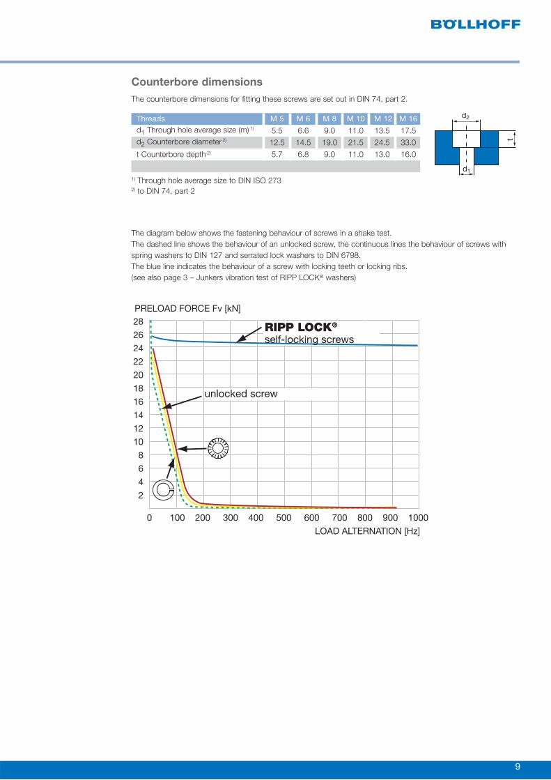
Counterbore dimensionsThe counterbore dimensions for fitting these screws are set out in DIN 74, part 2.
1) Through hole average size to DIN ISO 2732) to DIN 74, part 2
Threads M 5 M 6 M 8 M 10 M 12 M 16d1 Through hole average size (m) 1) 5.5 6.6 9.0 11.0 13.5 17.5d2 Counterbore diameter 2) 12.5 14.5 19.0 21.5 24.5 33.0t Counterbore depth 2) 5.7 6.8 9.0 11.0 13.0 16.0
d2
t
d1
unlocked screw
0 100 200 300 400 500 600 700 800 900 1000
28
26
24
22
20
18
16
14
12
10
8
6
4
2
LOAD ALTERNATION [Hz]
PRELOAD FORCE Fv [kN]
RIPP LOCK®
self-locking screws
The diagram below shows the fastening behaviour of screws in a shake test.The dashed line shows the behaviour of an unlocked screw, the continuous lines the behaviour of screws withspring washers to DIN 127 and serrated lock washers to DIN 6798. The blue line indicates the behaviour of a screw with locking teeth or locking ribs.(see also page 3 – Junkers vibration test of RIPP LOCK® washers)
10
d1 m s
d
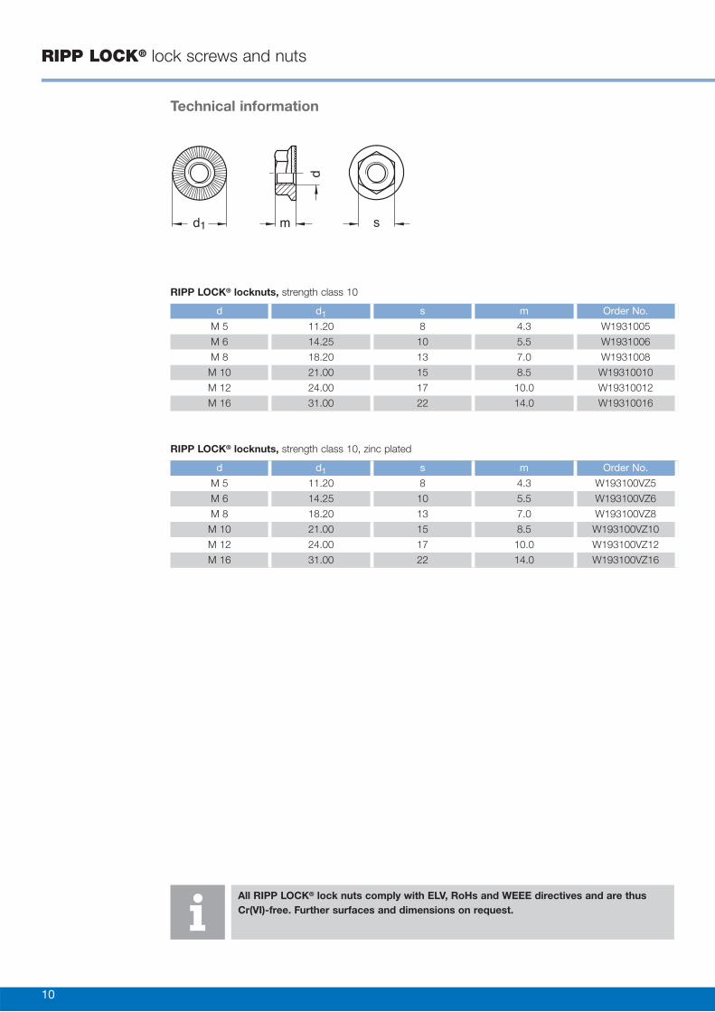
Technical information
RIPP LOCK® locknuts, strength class 10
RIPP LOCK® locknuts, strength class 10, zinc plated
RIPP LOCK® lock screws and nuts
All RIPP LOCK® lock nuts comply with ELV, RoHs and WEEE directives and are thusCr(VI)-free. Further surfaces and dimensions on request.
d d1 s m Order No.M 5 11.20 8 4.3 W1931005M 6 14.25 10 5.5 W1931006M 8 18.20 13 7.0 W1931008
M 10 21.00 15 8.5 W19310010M 12 24.00 17 10.0 W19310012M 16 31.00 22 14.0 W19310016
d d1 s m Order No.M 5 11.20 8 4.3 W193100VZ5M 6 14.25 10 5.5 W193100VZ6M 8 18.20 13 7.0 W193100VZ8
M 10 21.00 15 8.5 W193100VZ10M 12 24.00 17 10.0 W193100VZ12M 16 31.00 22 14.0 W193100VZ16
11
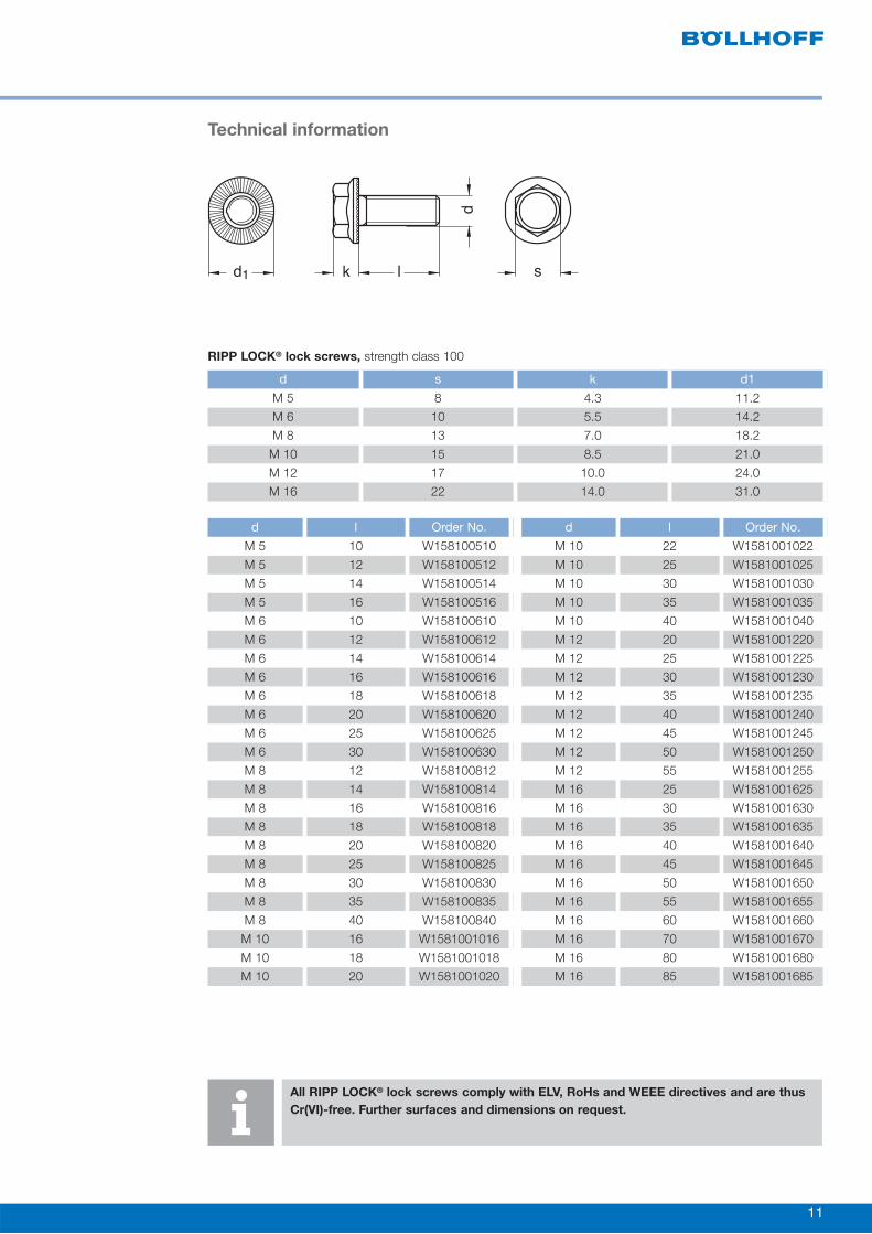
All RIPP LOCK® lock screws comply with ELV, RoHs and WEEE directives and are thusCr(VI)-free. Further surfaces and dimensions on request.
d1 lk s
d
Technical information
RIPP LOCK® lock screws, strength class 100
d l Order No.M 5 10 W158100510M 5 12 W158100512M 5 14 W158100514M 5 16 W158100516M 6 10 W158100610M 6 12 W158100612M 6 14 W158100614M 6 16 W158100616M 6 18 W158100618M 6 20 W158100620M 6 25 W158100625M 6 30 W158100630M 8 12 W158100812M 8 14 W158100814M 8 16 W158100816M 8 18 W158100818M 8 20 W158100820M 8 25 W158100825M 8 30 W158100830M 8 35 W158100835M 8 40 W158100840M 10 16 W1581001016M 10 18 W1581001018M 10 20 W1581001020
d l Order No.M 10 22 W1581001022M 10 25 W1581001025M 10 30 W1581001030M 10 35 W1581001035M 10 40 W1581001040M 12 20 W1581001220M 12 25 W1581001225M 12 30 W1581001230M 12 35 W1581001235M 12 40 W1581001240M 12 45 W1581001245M 12 50 W1581001250M 12 55 W1581001255M 16 25 W1581001625M 16 30 W1581001630M 16 35 W1581001635M 16 40 W1581001640M 16 45 W1581001645M 16 50 W1581001650M 16 55 W1581001655M 16 60 W1581001660M 16 70 W1581001670M 16 80 W1581001680M 16 85 W1581001685
d s k d1M 5 8 4.3 11.2M 6 10 5.5 14.2M 8 13 7.0 18.2M 10 15 8.5 21.0M 12 17 10.0 24.0M 16 22 14.0 31.0
12
d1 lk s
d
Technical information
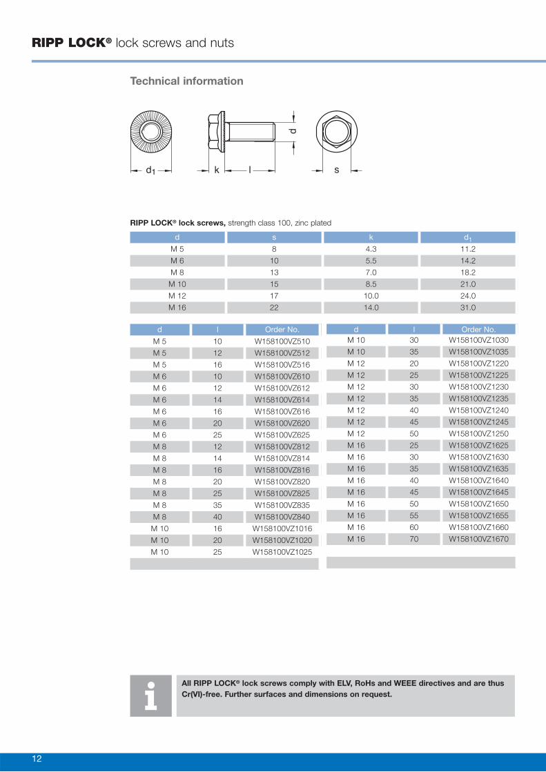
RIPP LOCK® lock screws, strength class 100, zinc plated
d l Order No.M 5 10 W158100VZ510M 5 12 W158100VZ512M 5 16 W158100VZ516M 6 10 W158100VZ610M 6 12 W158100VZ612M 6 14 W158100VZ614M 6 16 W158100VZ616M 6 20 W158100VZ620M 6 25 W158100VZ625M 8 12 W158100VZ812M 8 14 W158100VZ814M 8 16 W158100VZ816M 8 20 W158100VZ820M 8 25 W158100VZ825M 8 35 W158100VZ835M 8 40 W158100VZ840
M 10 16 W158100VZ1016M 10 20 W158100VZ1020M 10 25 W158100VZ1025
d l Order No.M 10 30 W158100VZ1030M 10 35 W158100VZ1035M 12 20 W158100VZ1220M 12 25 W158100VZ1225M 12 30 W158100VZ1230M 12 35 W158100VZ1235M 12 40 W158100VZ1240M 12 45 W158100VZ1245M 12 50 W158100VZ1250M 16 25 W158100VZ1625M 16 30 W158100VZ1630M 16 35 W158100VZ1635M 16 40 W158100VZ1640M 16 45 W158100VZ1645M 16 50 W158100VZ1650M 16 55 W158100VZ1655M 16 60 W158100VZ1660M 16 70 W158100VZ1670
RIPP LOCK® lock screws and nuts
All RIPP LOCK® lock screws comply with ELV, RoHs and WEEE directives and are thusCr(VI)-free. Further surfaces and dimensions on request.
d s k d1M 5 8 4.3 11.2M 6 10 5.5 14.2M 8 13 7.0 18.2M 10 15 8.5 21.0M 12 17 10.0 24.0M 16 22 14.0 31.0
13
d1 lk s
d
Technical information
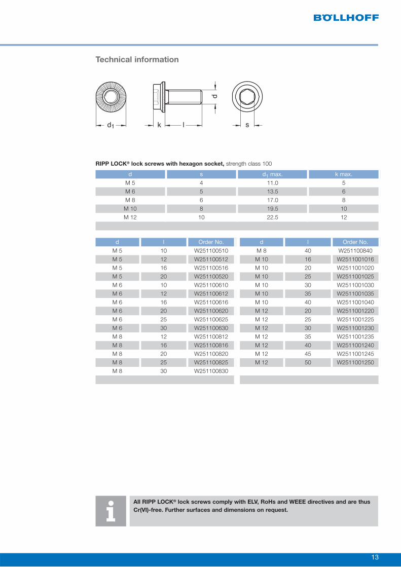
RIPP LOCK® lock screws with hexagon socket, strength class 100
d l Order No.M 5 10 W251100510M 5 12 W251100512M 5 16 W251100516M 5 20 W251100520M 6 10 W251100610M 6 12 W251100612M 6 16 W251100616M 6 20 W251100620M 6 25 W251100625M 6 30 W251100630M 8 12 W251100812M 8 16 W251100816M 8 20 W251100820M 8 25 W251100825M 8 30 W251100830
d l Order No.M 8 40 W251100840
M 10 16 W2511001016M 10 20 W2511001020M 10 25 W2511001025M 10 30 W2511001030M 10 35 W2511001035M 10 40 W2511001040M 12 20 W2511001220M 12 25 W2511001225M 12 30 W2511001230M 12 35 W2511001235M 12 40 W2511001240M 12 45 W2511001245M 12 50 W2511001250
All RIPP LOCK® lock screws comply with ELV, RoHs and WEEE directives and are thusCr(VI)-free. Further surfaces and dimensions on request.
d s d1 max. k max.M 5 4 11.0 5M 6 5 13.5 6M 8 6 17.0 8M 10 8 19.5 10M 12 10 22.5 12
14
d1 lk s
d
Technical information
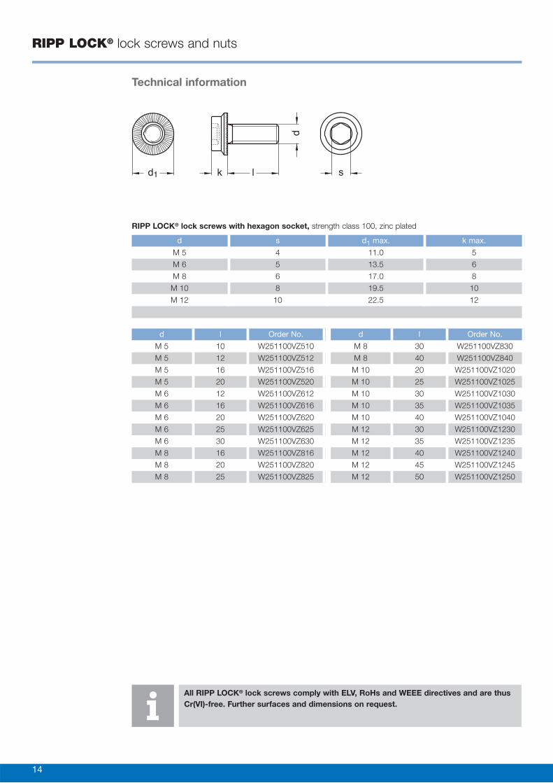
RIPP LOCK® lock screws with hexagon socket, strength class 100, zinc plated
d l Order No.M 5 10 W251100VZ510M 5 12 W251100VZ512M 5 16 W251100VZ516M 5 20 W251100VZ520M 6 12 W251100VZ612M 6 16 W251100VZ616M 6 20 W251100VZ620M 6 25 W251100VZ625M 6 30 W251100VZ630M 8 16 W251100VZ816M 8 20 W251100VZ820M 8 25 W251100VZ825
d l Order No.M 8 30 W251100VZ830M 8 40 W251100VZ840
M 10 20 W251100VZ1020M 10 25 W251100VZ1025M 10 30 W251100VZ1030M 10 35 W251100VZ1035M 10 40 W251100VZ1040M 12 30 W251100VZ1230M 12 35 W251100VZ1235M 12 40 W251100VZ1240M 12 45 W251100VZ1245M 12 50 W251100VZ1250
RIPP LOCK® lock screws and nuts
All RIPP LOCK® lock screws comply with ELV, RoHs and WEEE directives and are thusCr(VI)-free. Further surfaces and dimensions on request.
d s d1 max. k max.M 5 4 11.0 5M 6 5 13.5 6M 8 6 17.0 8M 10 8 19.5 10M 12 10 22.5 12
15
General technical approval
RIPP LOCK® lock screws and nuts – Approvals
ECOTECHSystem optimization in the joining technology
On the internet: http://www.boellhoff.de/de-en/ecotech
More interesting products for you
Registration number: Z-14.4-664
Object of approval:Bolted connection with RIPP LOCK® screw lock washers
The general technical approval verifies the screw-locking performance of the RIPP LOCK® washers in accordance with state building regulation.
RIPP LOCK® washers are tested and approved to secure the bolted connection,suitable even under high dynamic loads and under extreme vibration.
Systemoptimierung in der Verbindungstechnik
8505/10.01
ECOTECH Anwendungstechnik
Böllhoff International with companies in:Argentina
AustriaBrazil
CanadaChina
CzechiaFrance
GermanyHungary
IndiaItaly
JapanMexicoPoland
RomaniaRussia
SlovakiaSouth Korea
SpainSwitzerland
ThailandTurkey
United KingdomUSA
Apart from these 24 countries, Böllhoff supports its international customersin other important industrial markets in close partnership with agents and dealers.
Böllhoff GroupArchimedesstraße 1–4 · 33649 Bielefeld · Germany
Phone +49 521 4482 -952 · Fax +49 521 4482 -93952www.boellhoff.com · [email protected]
Subject to technical change. Reprinting, even in extract form, only permitted with express consent.Observe protective note according to ISO 16016.