Ring Main Unit - Schneider...
76
RM6 24 kV Medium Voltage Distribution Catalogue | 2012 Ring Main Unit Make the most of your energy
Transcript of Ring Main Unit - Schneider...
RM6 24 kV
Medium Voltage DistributionCatalogue | 2012
Ring Main Unit
Make the most of your energy

1AMTED398032EN
RM6 range Contents
Presentation 3
The RM6 range 11
Unit characteristics 17
Network remote control 39
Accessories 47
MV connection 55
Installation 61
Order form 67

2 AMTED398032EN.indd
3AMTED398032EN
Presentation Contents
Applications 4
Range advantages 6
Experience of a world leader 8
Protecting the environment 9
Quality - Standards 10
4 AMTED398032EN
MT5
5146
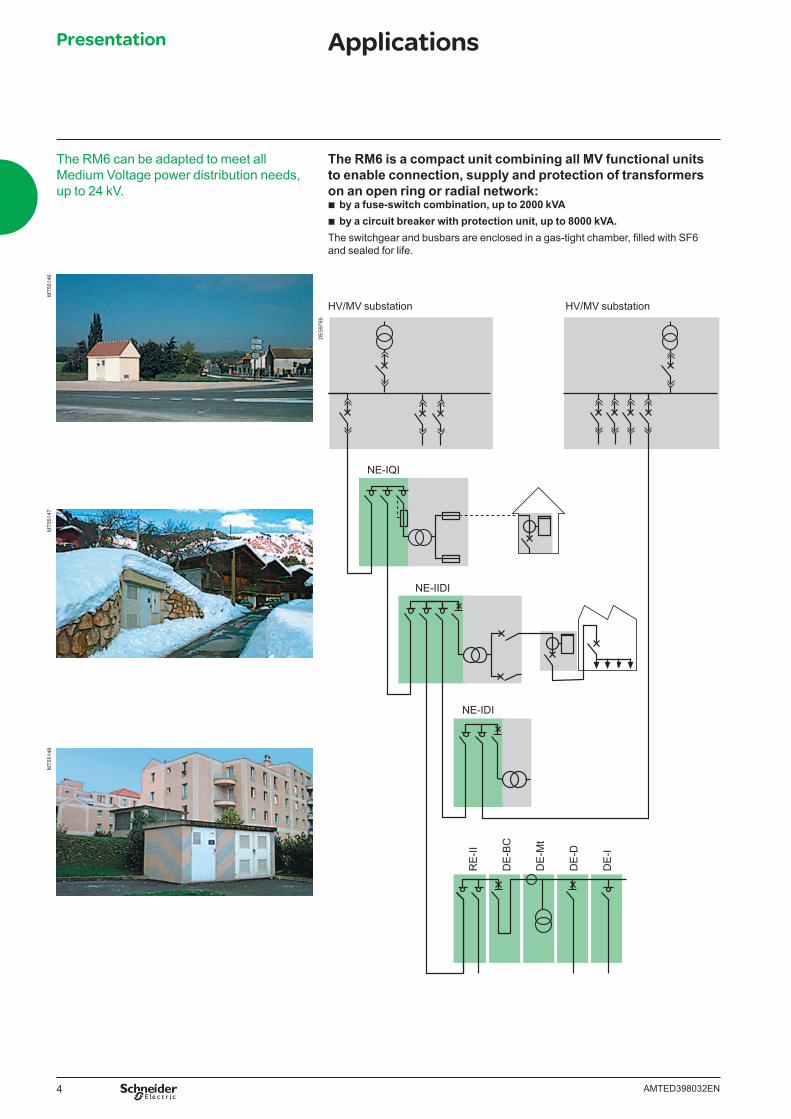
The RM6 can be adapted to meet all Medium Voltage power distribution needs, up to 24 kV.
MT5
5147
MT5
5148
The RM6 is a compact unit combining all MV functional units to enable connection, supply and protection of transformers on an open ring or radial network:
b by a fuse-switch combination, up to 2000 kVA b by a circuit breaker with protection unit, up to 8000 kVA.
The switchgear and busbars are enclosed in a gas-tight chamber, fi lled with SF6 and sealed for life.
Presentation Applications
HV/MV substation HV/MV substationD
E59
785
RE
-II
DE
-BC
DE
-Mt
DE
-D
DE
-I
NE-IDI
NE-IQI
NE-IIDI
5AMTED398032EN
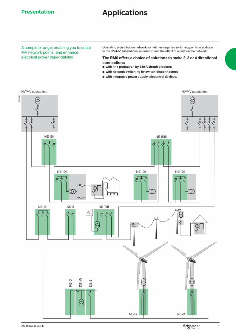
A complete range, enabling you to equip MV network points, and enhance electrical power dependability.
Operating a distribution network sometimes requires switching points in addition to the HV/MV substations, in order to limit the effect of a fault on the network.
The RM6 offers a choice of solutions to make 2, 3 or 4 directional connections
b with line protection by 630 A circuit breakers b with network switching by switch-disconnectors b with integrated power supply telecontrol devices.
Presentation Applications
HV/MV substation HV/MV substation
DE
5976
1
NE-IBI
NE-IDI
NE-IBI NE-II NE-TIII
NE-IDI NE-IDI
NE-BIBI
RE
-O
DE
-Mt
DE
-B
NE-D NE-D
6 AMTED398032EN
Advantages of a proven designRM6 switchgear
b Ensures personal safety: v internal arc withstand in conformity with IEC 62271-200 v visible earthing v 3 position switchgear for natural interlocking v dependable position indicating devices. b Is insensitive to the environment: v stainless steel sealed tank v disconnectable, sealed, metallized fuse chambers. b Is of approved quality: v conforms to national and international standards v design and production are certifi ed to ISO 9000 (version 2008) v benefi ts from the experience accumulated from 1,000,000 functional units
installed world-wide. b Respects the environment: v end-of-life gas recovery possible v ISO 14001 approved production site. b Is simple and rapid to install: v front cable connections at the same height v easily fi xed to the fl oor with 4 bolts. b Is economical: v from 1 to 4 functional units, integrated within the same metal enclosure
for which insulation and breaking take place in SF6 gas v lifetime of 30 years. b Has maintenance free live parts: v in conformity with IEC 62271-1, pressure system, sealed for life.
0448
9
1983 20071987
0381
78
0554
08
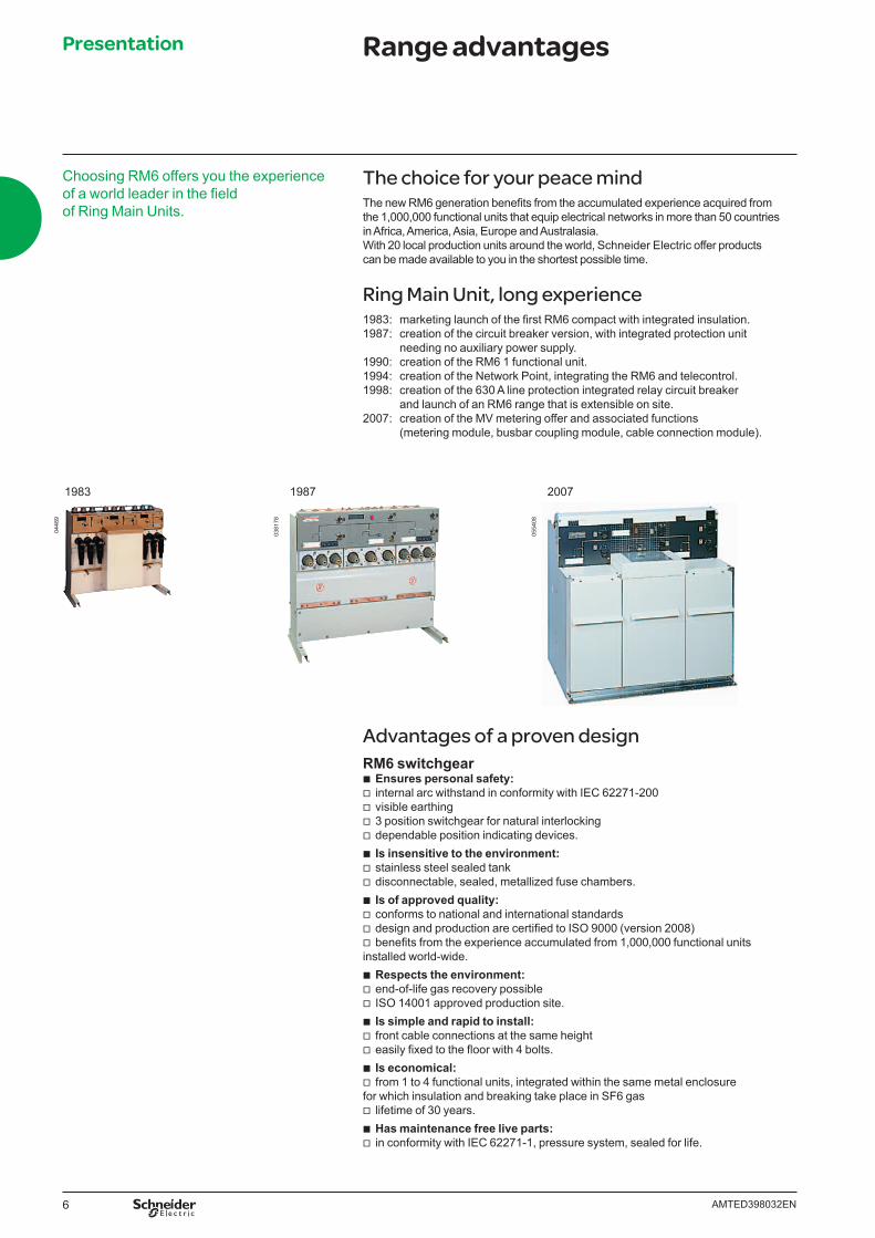
The choice for your peace mindThe new RM6 generation benefi ts from the accumulated experience acquired from the 1,000,000 functional units that equip electrical networks in more than 50 countries in Africa, America, Asia, Europe and Australasia.With 20 local production units around the world, Schneider Electric offer products can be made available to you in the shortest possible time.
Ring Main Unit, long experience1983: marketing launch of the fi rst RM6 compact with integrated insulation.1987: creation of the circuit breaker version, with integrated protection unit needing no auxiliary power supply.1990: creation of the RM6 1 functional unit.1994: creation of the Network Point, integrating the RM6 and telecontrol.1998: creation of the 630 A line protection integrated relay circuit breaker and launch of an RM6 range that is extensible on site.2007: creation of the MV metering offer and associated functions (metering module, busbar coupling module, cable connection module).
Choosing RM6 offers you the experience of a world leader in the fi eld of Ring Main Units.
Presentation Range advantages
7AMTED398032EN
Compact and scalable, the RM6 range covers all of your requirementsCompactRM6 Medium Voltage switchgear cubicles are perfectly suited for very simple confi guration of 1 to 4 functions.
b Choice of “all in one” units integrated in a single metal enclosure b Cubicles insensitive to climatic conditions b Optimized dimensions b Quick installation through fl oor fi xing with four bolts and front cable connection.
ExtensibleJust as compact and insensitive to climatic conditions the extensible RM6 is modular to suit your requirements.The addition of functional unit modules, allows you to build the Medium Voltage switchboard suited to your requirements.Your organization develops, you build a new building - RM6 adapts with you. It can be extended on site without handling gases or requiring any special fl oor preparation to develop your installation simply and in complete safety.
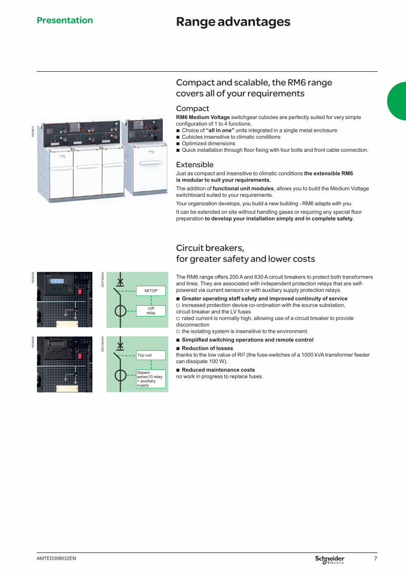
Circuit breakers, for greater safety and lower costs
The RM6 range offers 200 A and 630 A circuit breakers to protect both transformers and lines. They are associated with independent protection relays that are self-powered via current sensors or with auxiliary supply protection relays.
b Greater operating staff safety and improved continuity of service v increased protection device co-ordination with the source substation,
circuit breaker and the LV fuses v rated current is normally high, allowing use of a circuit breaker to provide
disconnection v the isolating system is insensitive to the environment. b Simplifi ed switching operations and remote control b Reduction of losses
thanks to the low value of RI2 (the fuse-switches of a 1000 kVA transformer feeder can dissipate 100 W).
b Reduced maintenance costsno work in progress to replace fuses.
PE
5829
2P
E56
811
Presentation Range advantagesP
E56
828
Trip coil
Sepam series10 relay+ auxiliarysupply
MITOP
VIPrelay
DE
5798
3EN
DE
5798
2EN

8 AMTED398032EN
RM6, a world-wide product
Main referencesAsia/Middle East
b BSED, Bahrein b DEWA, Dubaï b WED, Abu Dhabi b Tianjin Taifeng Industrial Park, China b TNB, Malaysia b China Steel Corporation, Taiwan b TPC, Taiwan b SCECO/SEC, Saudi Arabia b PSB, China
Africa b Electricité de Mayotte b EDF Reunion b Total, Libya b SONEL, Cameroon b South Africa
South America/Pacifi c b CELESC, Santa Catarina, Brazil b PETROBRAS, Rio de Janeiro, Brazil b Guarulhos International Airport b Sao Paulo, Brazil b CEMIG, Minas Gerais, Brazil
b EDF, French Guiana b Tahiti Electricity b Métro de Mexico, Mexico
Europe b EDF, France b Channel tunnel, France b Iberdrola, Spain b Compagnie Vaudoise d’électricité
SEIC, Switzerland b Electrabel, Belgium b Union Fenosa, Spain b ENHER, Spain b Oslo Energie, Norway b STOEN, Poland b Bayernwerke, Germany b London Electricity, United Kingdom b Mosenergo, Russia
Oceania b Eau et Electricité de Calédonie b New-Caledonia b Enercal, New-Caledonia b United Energy, Australia
MT5
5156
MT5
5157
MT5
5159
MT5
5160
MT5
5158
Norway Sweden
Spain Australia
Russia
DE
5703
6
Presentation Experience of a world leader
9AMTED398032EN
The Schneider Electric’s recycling procedure for SF6 based products is subject to rigorous management, and allows each device to be traced through to its fi nal destruction documentation.
The Schneider Electric’s recycling procedure
MT5
5136
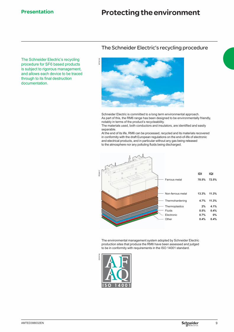
Schneider Electric is committed to a long term environmental approach. As part of this, the RM6 range has been designed to be environmentally friendly, notably in terms of the product’s recycleability.The materials used, both conductors and insulators, are identifi ed and easily separable.At the end of its life, RM6 can be processed, recycled and its materials recovered in conformity with the draft European regulations on the end-of-life of electronic and electrical products, and in particular without any gas being released to the atmosphere nor any polluting fl uids being discharged.
PE
5681
7
IDI IQI
Ferrous metal 78.5% 72.5%
Non-ferrous metal 13.3% 11.3%
Thermohardening 4.7% 11.3%
Thermoplastics 2% 4.1%Fluids 0.5% 0.4%Electronic 0.7% 0%Other 0.4% 0.4%
The environmental management system adopted by Schneider Electric production sites that produce the RM6 have been assessed and judged to be in conformity with requirements in the ISO 14001 standard.
DE
5574
6
Presentation Protecting the environment
10 AMTED398032EN
IEC standardsRM6 is designed in accordance with the following standards:
General operation conditions for indoor switchgearsIEC 62271-1 (common specifi cations for high voltage switchgear and controlgear)
b Ambient temperature: class –25°C indoor v lower than or equal to 40°C without derating v lower than or equal to 35°C on 24 hours average without derating v greater than or equal to –25°C. b Altitude : v lower than or equal to 1000 m v above 1000 m, and up to 2000 m with directed fi eld connectors v greater than 2000 m: please consult us for specifi c precaution.
IEC 62271-200 (A.C. metal enclosed switchgear and controlgear for rated voltage above 1 kV and up to and including 52 kV)
b Switchgear classifi cation: PM class (metallic partitioning) b Loss of service continuity: LSC2B class for circuit breaker and switch
(LSC2A for fuse-switch combinations) b Internal arc classifi cation: class A-FL up to 20 kA 1 s on request
(access restricted to authorized personnel only, for front and lateral access).
Switch-disconnectors IEC 62271-103 (high voltage switches for rated voltage above 1 kV and less than 52 kV)
b Class M1/E3 v 100 CO cycles at rated current and 0.7 p.f. v 1000 mechanical opening operations.
Circuit breakers: 200 A feeder or 630 A line protection IEC 62271-100 (high voltage alternating current circuit breakers)
b Class M1/E2 v 2000 mechanical opening operations, v O-3 min.-CO-3 min.-CO cycle at rated short circuit current.
Other applicable standards b Switch-fuse combinations: IEC 62271-105:
alternating current switch-fuse combination b Earthing switch: IEC 62271-102:
alternating current disconnectors and earthing switches b Electrical relays: IEC 60255.
A major plus pointSchneider Electric has integrated a functional organization into each of its units, the main purpose of which is to check quality and ensure the adherence to standards.This procedure is:
b the same throughout the different departments b recognized by numerous approved customers and organizations.
Above all, it is our strict application of this functional organization that has enabled us to obtain the recognition of an independent organization, the French Association for Quality Assurance (Association Française pour l’Assurance Qualité, or (AFAQ).The RM6 design and production quality system has been certifi ed as being in conformity with the requirements of the ISO 9001: 2008 quality assurance model.
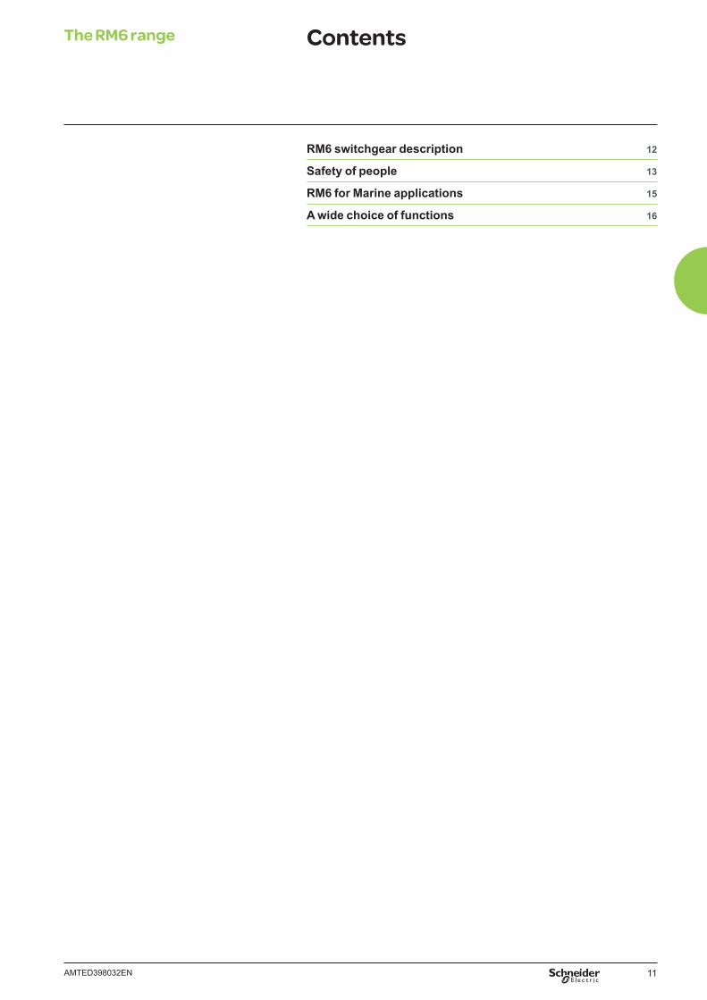
Rigorous, systematic checksDuring the manufacture of each RM6, it undergoes systematic routine tests, the aim of which is to check quality and conformity:
b tightness check b fi lling pressure check b opening and closing speed measurement b operating torque measurement b partial discharge check b dielectric check b conformity with drawings and diagrams.
The quality control department records and signs the results obtained on the test certifi cate for each device. There is “zero” SF6 emission during the gas fi lling and tightness control process.
DE
5978
8P
E58
290
Presentation Quality - Standards
11AMTED398032EN
The RM6 range Contents
RM6 switchgear description 12
Safety of people 13
RM6 for Marine applications 15
A wide choice of functions 16
12 AMTED398032EN
PE
5681
2 RM6 switchgear comprises 1 to 4 integrated, low dimension functional units.This self-contained, totally insulated unit comprises:
b a stainless steel, gas-tight metal enclosure, sealed for life, which groups together the live parts, switch-disconnector, earthing switch, fuse switch or the circuit breaker
b one to four cable compartments with interfaces for connection to the network or to the transformer
b a low voltage cabinet b an electrical operating mechanism cabinet b a fuse chamber compartment for fused switch-disconnectors or fuse switches.
The performance characteristics obtained by the RM6 meet the defi nition of a “sealed pressure system” laid down in the IEC recommendations.The switch-disconnector and the earthing switch offer the operator all necessary usage guarantees:TightnessThe enclosure is fi lled with SF6 at a 0.2 bar gauge pressure. It is sealed for life after fi lling. Its tightness, which is systematically checked at the factory, gives the switchgear an expected lifetime of 30 years. No maintenance of live parts is necessary with the RM6 breaking.Switch-disconnectorElectrical arc extinction is obtained using the SF6 puffer technique.Circuit breakerElectrical arc extinction is obtained using the rotating arc technique plus SF6auto-expansion, allowing breaking of all currents up to the short-circuit current.
A range that is extensible on siteWhen harsh climatic conditions or environmental restrictions make it necessary to use compact switchgear, but the foreseeable evolution of the power distribution network makes it necessary to provide for future changes, RM6 offers a range of extensible switchgear.The addition of one or more functional units can be carried out by simply adding modules that are connected to each other at busbar level by directed fi eld bushings.This very simple operation can be carried out on-site:
b without handling any gas b without any special tooling b without any particular preparation of the fl oor.
The only technical limitation to the evolution of an extensible RM6 switchboard is therefore the rated current acceptable by the busbar: 630 A at 40°C.
Insensitivity to the environmentComplete insulation
b A metal enclosure made of stainless steel, which is unpainted and gas-tight (IP67), contains the live parts of the switchgear and the busbars.
b Three sealed fuse chambers, which are disconnectable and metallized on the outside, insulate the fuses from dust, humidity...
b Metallization of the fuse chambers and directed fi eld terminal connectors confi nes the electrical fi eld in the solid insulation.Taken together, the above elements provide the RM6 with genuine total insulation which makes the switchgear completely insensitive to environmental conditions, dust, extreme humidity, temporary soaking.(IP67: immersion for 30 minutes, as laid down in IEC standard 60529, § 14.2.7).
PE
5829
305
5749
The RM6 range RM6 switchgear description
13AMTED398032EN
0557
5005
5746
0557
52
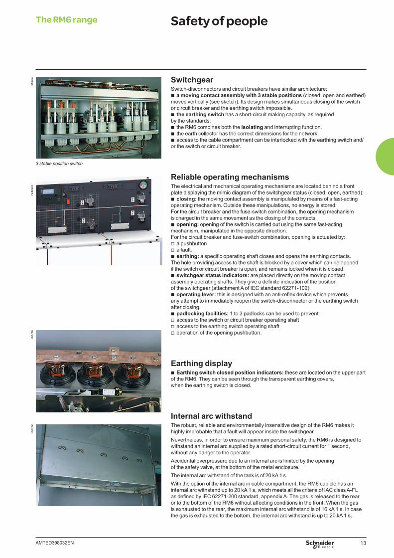
SwitchgearSwitch-disconnectors and circuit breakers have similar architecture:
b a moving contact assembly with 3 stable positions (closed, open and earthed) moves vertically (see sketch). Its design makes simultaneous closing of the switch or circuit breaker and the earthing switch impossible.
b the earthing switch has a short-circuit making capacity, as required by the standards.
b the RM6 combines both the isolating and interrupting function. b the earth collector has the correct dimensions for the network. b access to the cable compartment can be interlocked with the earthing switch and/
or the switch or circuit breaker.
Reliable operating mechanismsThe electrical and mechanical operating mechanisms are located behind a front plate displaying the mimic diagram of the switchgear status (closed, open, earthed):
b closing: the moving contact assembly is manipulated by means of a fast-acting operating mechanism. Outside these manipulations, no energy is stored.For the circuit breaker and the fuse-switch combination, the opening mechanism is charged in the same movement as the closing of the contacts.
b opening: opening of the switch is carried out using the same fast-acting mechanism, manipulated in the opposite direction.For the circuit breaker and fuse-switch combination, opening is actuated by:
v a pushbutton v a fault. b earthing: a specifi c operating shaft closes and opens the earthing contacts.
The hole providing access to the shaft is blocked by a cover which can be opened if the switch or circuit breaker is open, and remains locked when it is closed.
b switchgear status indicators: are placed directly on the moving contact assembly operating shafts. They give a defi nite indication of the position of the switchgear (attachment A of IEC standard 62271-102).
b operating lever: this is designed with an anti-refl ex device which prevents any attempt to immediately reopen the switch-disconnector or the earthing switch after closing.
b padlocking facilities: 1 to 3 padlocks can be used to prevent: v access to the switch or circuit breaker operating shaft v access to the earthing switch operating shaft v operation of the opening pushbutton.
Earthing display b Earthing switch closed position indicators: these are located on the upper part
of the RM6. They can be seen through the transparent earthing covers, when the earthing switch is closed.
Internal arc withstandThe robust, reliable and environmentally insensitive design of the RM6 makes it highly improbable that a fault will appear inside the switchgear. Nevertheless, in order to ensure maximum personal safety, the RM6 is designed to withstand an internal arc supplied by a rated short-circuit current for 1 second, without any danger to the operator.Accidental overpressure due to an internal arc is limited by the opening of the safety valve, at the bottom of the metal enclosure. The internal arc withstand of the tank is of 20 kA 1 s. With the option of the internal arc in cable compartment, the RM6 cubicle has an internal arc withstand up to 20 kA 1 s, which meets all the criteria of IAC class A-FL as defi ned by IEC 62271-200 standard, appendix A. The gas is released to the rear or to the bottom of the RM6 without affecting conditions in the front. When the gas is exhausted to the rear, the maximum internal arc withstand is of 16 kA 1 s. In case the gas is exhausted to the bottom, the internal arc withstand is up to 20 kA 1 s.
PE
5829
4
3 stable position switch
The RM6 range Safety of people
14 AMTED398032EN
0557
57P
E56
418
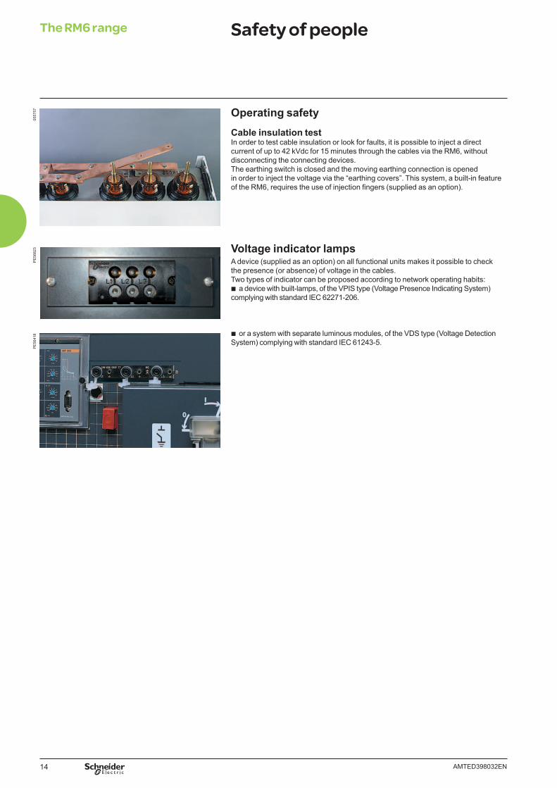
Operating safetyCable insulation testIn order to test cable insulation or look for faults, it is possible to inject a direct current of up to 42 kVdc for 15 minutes through the cables via the RM6, without disconnecting the connecting devices.The earthing switch is closed and the moving earthing connection is opened in order to inject the voltage via the “earthing covers”. This system, a built-in feature of the RM6, requires the use of injection fi ngers (supplied as an option).
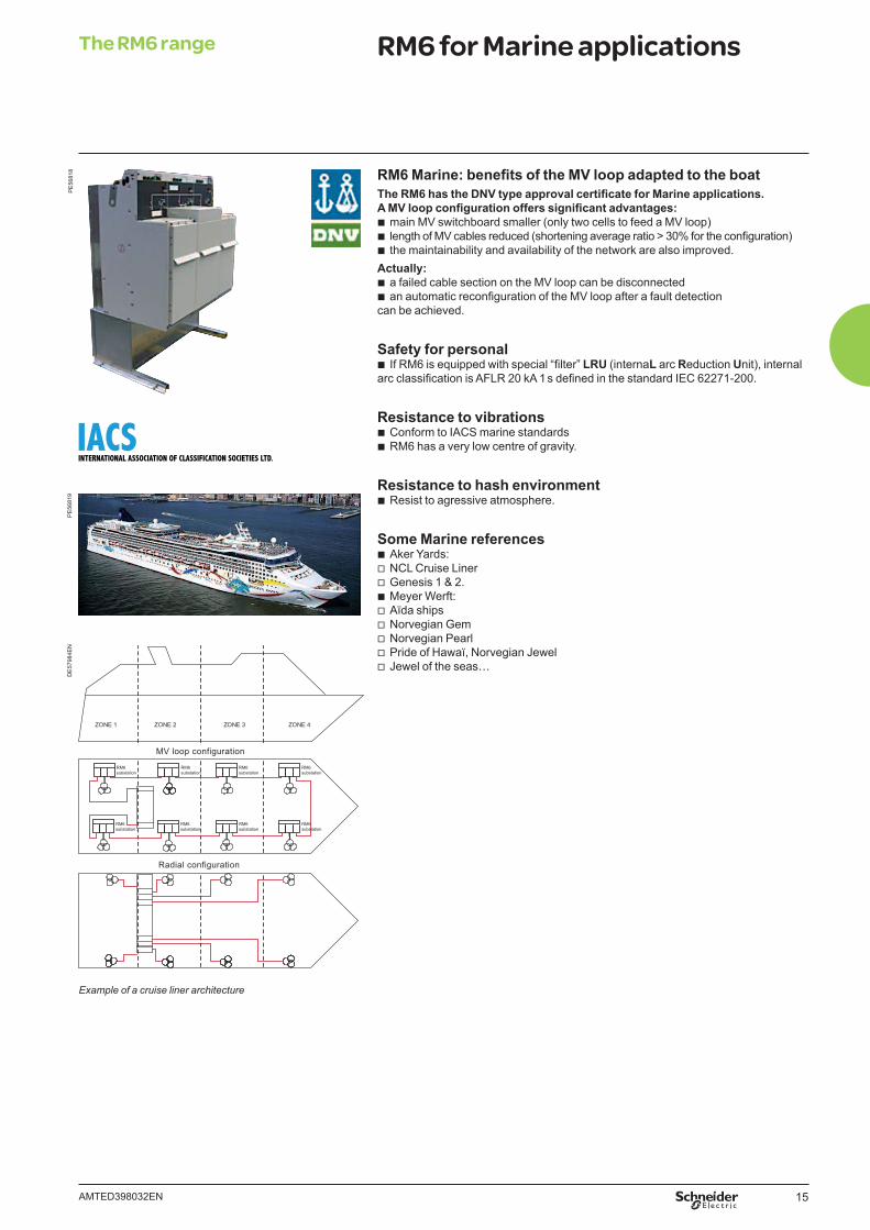
Voltage indicator lampsA device (supplied as an option) on all functional units makes it possible to check the presence (or absence) of voltage in the cables.Two types of indicator can be proposed according to network operating habits:
b a device with built-lamps, of the VPIS type (Voltage Presence Indicating System) complying with standard IEC 62271-206.
b or a system with separate luminous modules, of the VDS type (Voltage Detection System) complying with standard IEC 61243-5.
The RM6 range Safety of peopleP
E56
823
15AMTED398032EN
The RM6 range RM6 for Marine applications
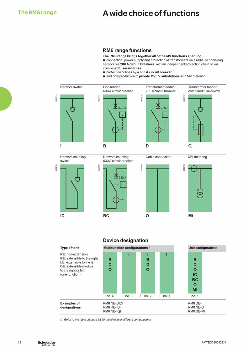
RM6 Marine: benefi ts of the MV loop adapted to the boatThe RM6 has the DNV type approval certifi cate for Marine applications.A MV loop confi guration offers signifi cant advantages:
b main MV switchboard smaller (only two cells to feed a MV loop) b length of MV cables reduced (shortening average ratio > 30% for the confi guration) b the maintainability and availability of the network are also improved.
Actually: b a failed cable section on the MV loop can be disconnected b an automatic reconfi guration of the MV loop after a fault detection
can be achieved.
Safety for personal b If RM6 is equipped with special “fi lter” LRU (internaL arc Reduction Unit), internal
arc classifi cation is AFLR 20 kA 1 s defi ned in the standard IEC 62271-200.
Resistance to vibrations b Conform to IACS marine standards b RM6 has a very low centre of gravity.
Resistance to hash environment b Resist to agressive atmosphere.
Some Marine references b Aker Yards: v NCL Cruise Liner v Genesis 1 & 2. b Meyer Werft: v Aïda ships v Norvegian Gem v Norvegian Pearl v Pride of Hawaï, Norvegian Jewel v Jewel of the seas…
PE
5681
8P
E56
819
Example of a cruise liner architecture
RM6substation
RM6substation
RM6substation
RM6substation
RM6substation
RM6substation
RM6substation
RM6substation
Radial configuration
MV loop configuration
DE
5798
4EN
16 AMTED398032EN
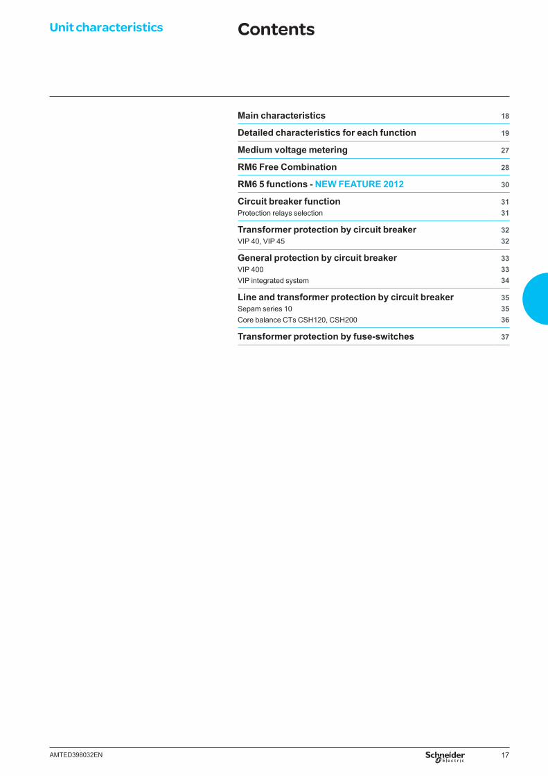
RM6 range functionsThe RM6 range brings together all of the MV functions enabling:
b connection, power supply and protection of transformers on a radial or open-ring network via 200 A circuit breakers with an independent protection chain or via combined fuse-switches
b protection of lines by a 630 A circuit breaker b and now production of private MV/LV substations with MV metering.
Network switch Line feeder 630 A circuit breaker
Transformer feeder 200 A circuit breaker
Transformer feeder combined fuse-switch
DE
5975
9
DE
5973
5
630 A
DE
5973
6
200 A
DE
5973
7
I B D Q
Network coupling switch
Network coupling 630 A circuit breaker
Cable connection MV metering
DE
5973
8
DE
5973
9
630 A
DE
5974
0
DE
5974
1
IC BC O Mt
Device designationType of tank Multifunction confi gurations * Unit confi gurations
NE: non-extensibleRE: extensible to the rightLE: extensible to the leftDE: extensible module to the right or left (one function)
IBDQ
I IBDQ
I IBDQICBCOMt
no. 4 no. 3 no. 2 no. 1 no. 1
Examples of designations
RM6 NE-DIDIRM6 RE-IDIRM6 NE-IQI
RM6 DE-IRM6 NE-DRM6 DE-Mt
(*) Refer to the table on page 68 for the choice of different combinations
The RM6 range A wide choice of functions
17AMTED398032EN
Unit characteristics Contents
Main characteristics 18
Detailed characteristics for each function 19
Medium voltage metering 27
RM6 Free Combination 28
RM6 5 functions - NEW FEATURE 2012 30
Circuit breaker function Protection relays selection
3131
Transformer protection by circuit breaker VIP 40, VIP 45
3232
General protection by circuit breakerVIP 400 VIP integrated system
333334
Line and transformer protection by circuit breakerSepam series 10Core balance CTs CSH120, CSH200
353536
Transformer protection by fuse-switches 37
18 AMTED398032EN
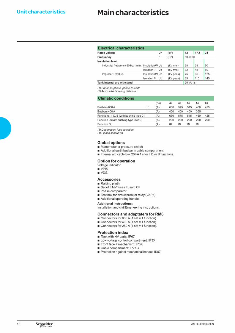
Electrical characteristicsRated voltage Ur (kV) 12 17.5 24Frequency f (Hz) 50 or 60Insulation level
Industrial frequency 50 Hz 1 min. Insulation (1) Ud (kV rms) 28 38 50Isolation (2) Ud (kV rms) 32 45 60
Impulse 1.2/50 μs Insulation (1) Up (kV peak) 75 95 125Isolation (2) Up (kV peak) 85 110 145
Tank internal arc withstand 20 kA 1 s
(1) Phase-to-phase, phase-to-earth(2) Across the isolating distance.
Climatic conditions(°C) 40 45 50 55 60
Busbars 630 A Ir (A) 630 575 515 460 425Busbars 400 A Ir (A) 400 400 400 355Functions: I, O, B (with bushing type C) (A) 630 575 515 460 425Function D (with bushing type B or C) (A) 200 200 200 200 200Function Q (A) (3) (4) (4) (4)
(3) Depends on fuse selection(4) Please consult us.
Global options b Manometer or pressure switch b Additional earth busbar in cable compartment b Internal arc cable box 20 kA 1 s for I, D or B functions.
Option for operationVoltage indicator:
b VPIS b VDS.
Accessories b Raising plinth b Set of 3 MV fuses Fusarc CF b Phase comparator b Test box for circuit breaker relay (VAP6) b Additional operating handle.
Additional instructions:Installation and civil Engineering instructions.
Connectors and adaptaters for RM6 b Connectors for 630 A (1 set = 1 function) b Connectors for 400 A (1 set = 1 function) b Connectors for 250 A (1 set = 1 function).
Protection index b Tank with HV parts: IP67 b Low voltage control compartment: IP3X b Front face + mechanism: IP3X b Cable compartment: IP2XC b Protection against mechanical impact: IK07.
Unit characteristics Main characteristics
19AMTED398032EN
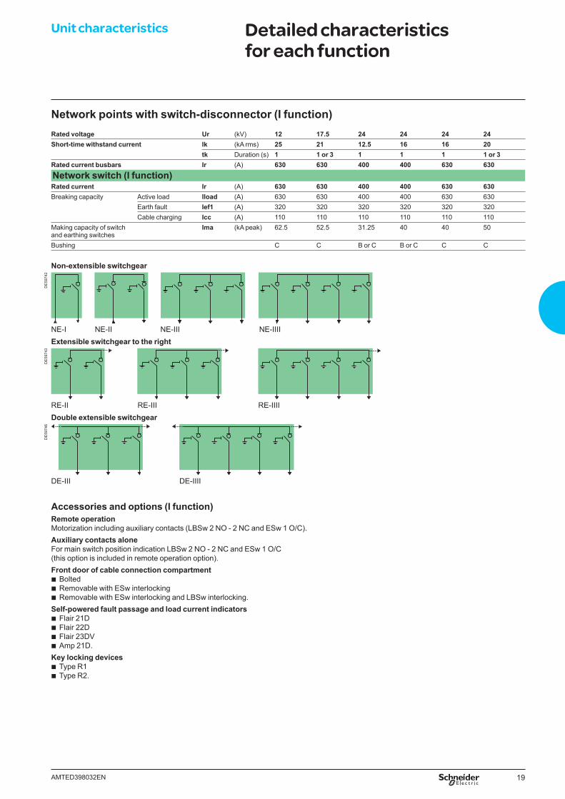
Network points with switch-disconnector (I function)Rated voltage Ur (kV) 12 17.5 24 24 24 24Short-time withstand current Ik (kA rms) 25 21 12.5 16 16 20
tk Duration (s) 1 1 or 3 1 1 1 1 or 3Rated current busbars Ir (A) 630 630 400 400 630 630Network switch (I function)Rated current Ir (A) 630 630 400 400 630 630Breaking capacity Active load Iload (A) 630 630 400 400 630 630
Earth fault Ief1 (A) 320 320 320 320 320 320Cable charging Icc (A) 110 110 110 110 110 110
Making capacity of switchand earthing switches
Ima (kA peak) 62.5 52.5 31.25 40 40 50
Bushing C C B or C B or C C C
Accessories and options (I function)Remote operationMotorization including auxiliary contacts (LBSw 2 NO - 2 NC and ESw 1 O/C).Auxiliary contacts aloneFor main switch position indication LBSw 2 NO - 2 NC and ESw 1 O/C(this option is included in remote operation option).Front door of cable connection compartment
b Bolted b Removable with ESw interlocking b Removable with ESw interlocking and LBSw interlocking.
Self-powered fault passage and load current indicators b Flair 21D b Flair 22D b Flair 23DV b Amp 21D.
Key locking devices b Type R1 b Type R2.
Unit characteristics Detailed characteristics for each function
Non-extensible switchgear
DE
5974
2
NE-I NE-II NE-III NE-IIIIExtensible switchgear to the right
DE
5974
3
RE-II RE-III RE-IIIIDouble extensible switchgear
DE
5974
6
DE-III DE-IIII
20 AMTED398032EN
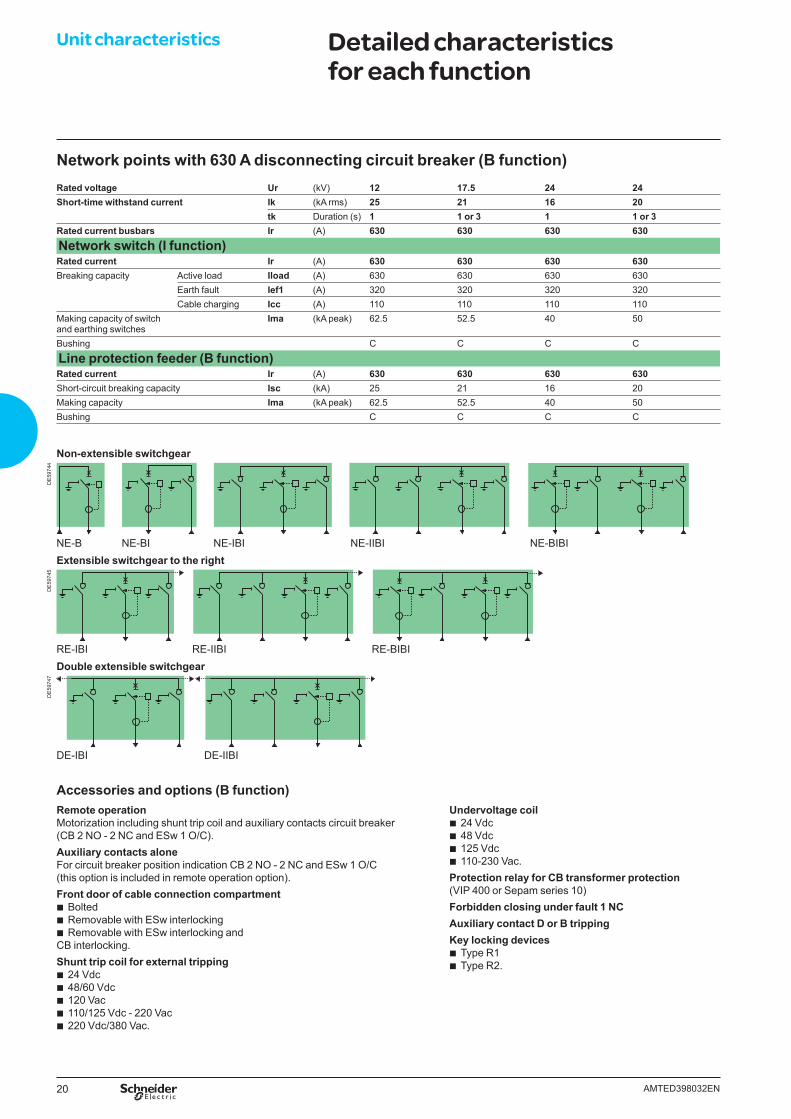
Network points with 630 A disconnecting circuit breaker (B function)Rated voltage Ur (kV) 12 17.5 24 24Short-time withstand current Ik (kA rms) 25 21 16 20
tk Duration (s) 1 1 or 3 1 1 or 3Rated current busbars Ir (A) 630 630 630 630Network switch (I function)Rated current Ir (A) 630 630 630 630Breaking capacity Active load Iload (A) 630 630 630 630
Earth fault Ief1 (A) 320 320 320 320Cable charging Icc (A) 110 110 110 110
Making capacity of switchand earthing switches
Ima (kA peak) 62.5 52.5 40 50
Bushing C C C C
Line protection feeder (B function)Rated current Ir (A) 630 630 630 630Short-circuit breaking capacity Isc (kA) 25 21 16 20Making capacity Ima (kA peak) 62.5 52.5 40 50Bushing C C C C
Unit characteristics Detailed characteristics for each function
Non-extensible switchgear
DE
5974
4
NE-B NE-BI NE-IBI NE-IIBI NE-BIBIExtensible switchgear to the right
DE
5974
5
RE-IBI RE-IIBI RE-BIBIDouble extensible switchgear
DE
5974
7
DE-IBI DE-IIBI
Accessories and options (B function)Remote operationMotorization including shunt trip coil and auxiliary contacts circuit breaker(CB 2 NO - 2 NC and ESw 1 O/C).Auxiliary contacts aloneFor circuit breaker position indication CB 2 NO - 2 NC and ESw 1 O/C(this option is included in remote operation option).Front door of cable connection compartment
b Bolted b Removable with ESw interlocking b Removable with ESw interlocking and
CB interlocking.Shunt trip coil for external tripping
b 24 Vdc b 48/60 Vdc b 120 Vac b 110/125 Vdc - 220 Vac b 220 Vdc/380 Vac.
Undervoltage coil b 24 Vdc b 48 Vdc b 125 Vdc b 110-230 Vac.
Protection relay for CB transformer protection (VIP 400 or Sepam series 10)Forbidden closing under fault 1 NC Auxiliary contact D or B trippingKey locking devices
b Type R1 b Type R2.
21AMTED398032EN
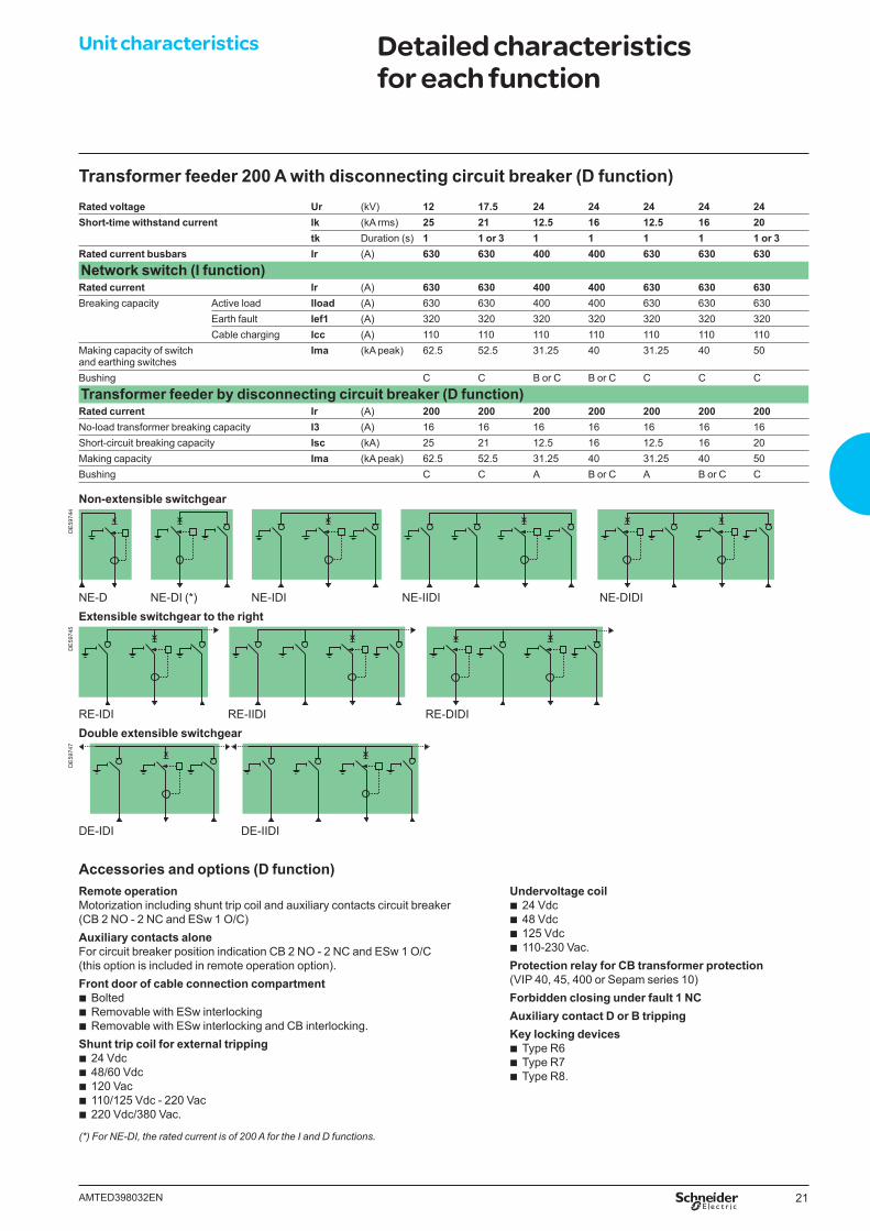
Transformer feeder 200 A with disconnecting circuit breaker (D function)Rated voltage Ur (kV) 12 17.5 24 24 24 24 24Short-time withstand current Ik (kA rms) 25 21 12.5 16 12.5 16 20
tk Duration (s) 1 1 or 3 1 1 1 1 1 or 3Rated current busbars Ir (A) 630 630 400 400 630 630 630Network switch (I function)Rated current Ir (A) 630 630 400 400 630 630 630Breaking capacity Active load Iload (A) 630 630 400 400 630 630 630
Earth fault Ief1 (A) 320 320 320 320 320 320 320Cable charging Icc (A) 110 110 110 110 110 110 110
Making capacity of switchand earthing switches
Ima (kA peak) 62.5 52.5 31.25 40 31.25 40 50
Bushing C C B or C B or C C C C
Transformer feeder by disconnecting circuit breaker (D function)Rated current Ir (A) 200 200 200 200 200 200 200No-load transformer breaking capacity I3 (A) 16 16 16 16 16 16 16Short-circuit breaking capacity Isc (kA) 25 21 12.5 16 12.5 16 20Making capacity Ima (kA peak) 62.5 52.5 31.25 40 31.25 40 50Bushing C C A B or C A B or C C
Unit characteristics Detailed characteristics for each function
Non-extensible switchgear
DE
5974
4
NE-D NE-DI (*) NE-IDI NE-IIDI NE-DIDIExtensible switchgear to the right
DE
5974
5
RE-IDI RE-IIDI RE-DIDIDouble extensible switchgear
DE
5974
7
DE-IDI DE-IIDI
Accessories and options (D function)Remote operationMotorization including shunt trip coil and auxiliary contacts circuit breaker(CB 2 NO - 2 NC and ESw 1 O/C) Auxiliary contacts aloneFor circuit breaker position indication CB 2 NO - 2 NC and ESw 1 O/C(this option is included in remote operation option).Front door of cable connection compartment
b Bolted b Removable with ESw interlocking b Removable with ESw interlocking and CB interlocking.
Shunt trip coil for external tripping b 24 Vdc b 48/60 Vdc b 120 Vac b 110/125 Vdc - 220 Vac b 220 Vdc/380 Vac.
Undervoltage coil b 24 Vdc b 48 Vdc b 125 Vdc b 110-230 Vac.
Protection relay for CB transformer protection (VIP 40, 45, 400 or Sepam series 10)Forbidden closing under fault 1 NC Auxiliary contact D or B trippingKey locking devices
b Type R6 b Type R7 b Type R8.
(*) For NE-DI, the rated current is of 200 A for the I and D functions.
22 AMTED398032EN
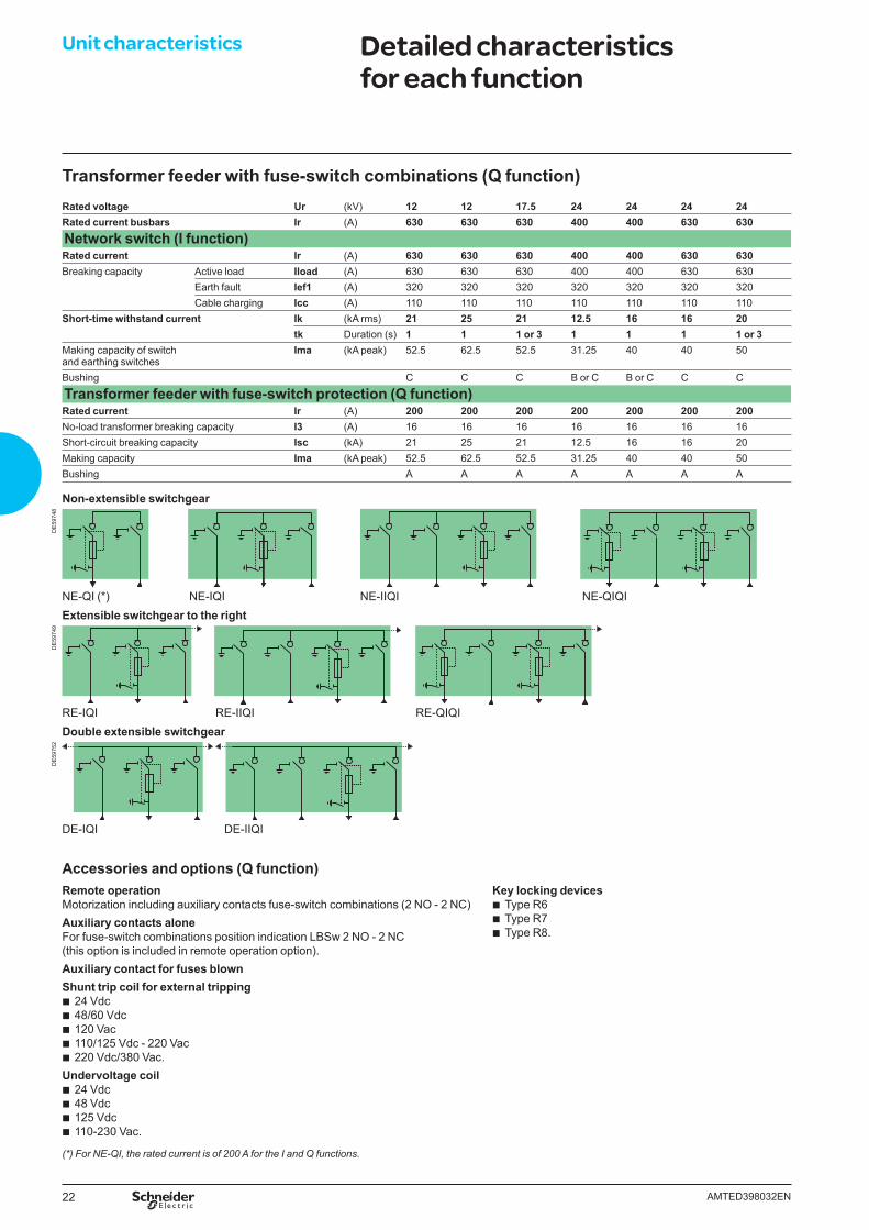
Transformer feeder with fuse-switch combinations (Q function)Rated voltage Ur (kV) 12 12 17.5 24 24 24 24Rated current busbars Ir (A) 630 630 630 400 400 630 630Network switch (I function)Rated current Ir (A) 630 630 630 400 400 630 630Breaking capacity Active load Iload (A) 630 630 630 400 400 630 630
Earth fault Ief1 (A) 320 320 320 320 320 320 320Cable charging Icc (A) 110 110 110 110 110 110 110
Short-time withstand current Ik (kA rms) 21 25 21 12.5 16 16 20tk Duration (s) 1 1 1 or 3 1 1 1 1 or 3
Making capacity of switchand earthing switches
Ima (kA peak) 52.5 62.5 52.5 31.25 40 40 50
Bushing C C C B or C B or C C C
Transformer feeder with fuse-switch protection (Q function)Rated current Ir (A) 200 200 200 200 200 200 200No-load transformer breaking capacity I3 (A) 16 16 16 16 16 16 16Short-circuit breaking capacity Isc (kA) 21 25 21 12.5 16 16 20Making capacity Ima (kA peak) 52.5 62.5 52.5 31.25 40 40 50Bushing A A A A A A A
Unit characteristics Detailed characteristics for each function
Non-extensible switchgear
DE
5974
8
NE-QI (*) NE-IQI NE-IIQI NE-QIQIExtensible switchgear to the right
DE
5974
9
RE-IQI RE-IIQI RE-QIQIDouble extensible switchgear
DE
5975
2
DE-IQI DE-IIQI
Accessories and options (Q function)Remote operationMotorization including auxiliary contacts fuse-switch combinations (2 NO - 2 NC)Auxiliary contacts aloneFor fuse-switch combinations position indication LBSw 2 NO - 2 NC(this option is included in remote operation option).Auxiliary contact for fuses blownShunt trip coil for external tripping
b 24 Vdc b 48/60 Vdc b 120 Vac b 110/125 Vdc - 220 Vac b 220 Vdc/380 Vac.
Undervoltage coil b 24 Vdc b 48 Vdc b 125 Vdc b 110-230 Vac.
Key locking devices b Type R6 b Type R7 b Type R8.
(*) For NE-QI, the rated current is of 200 A for the I and Q functions.
23AMTED398032EN
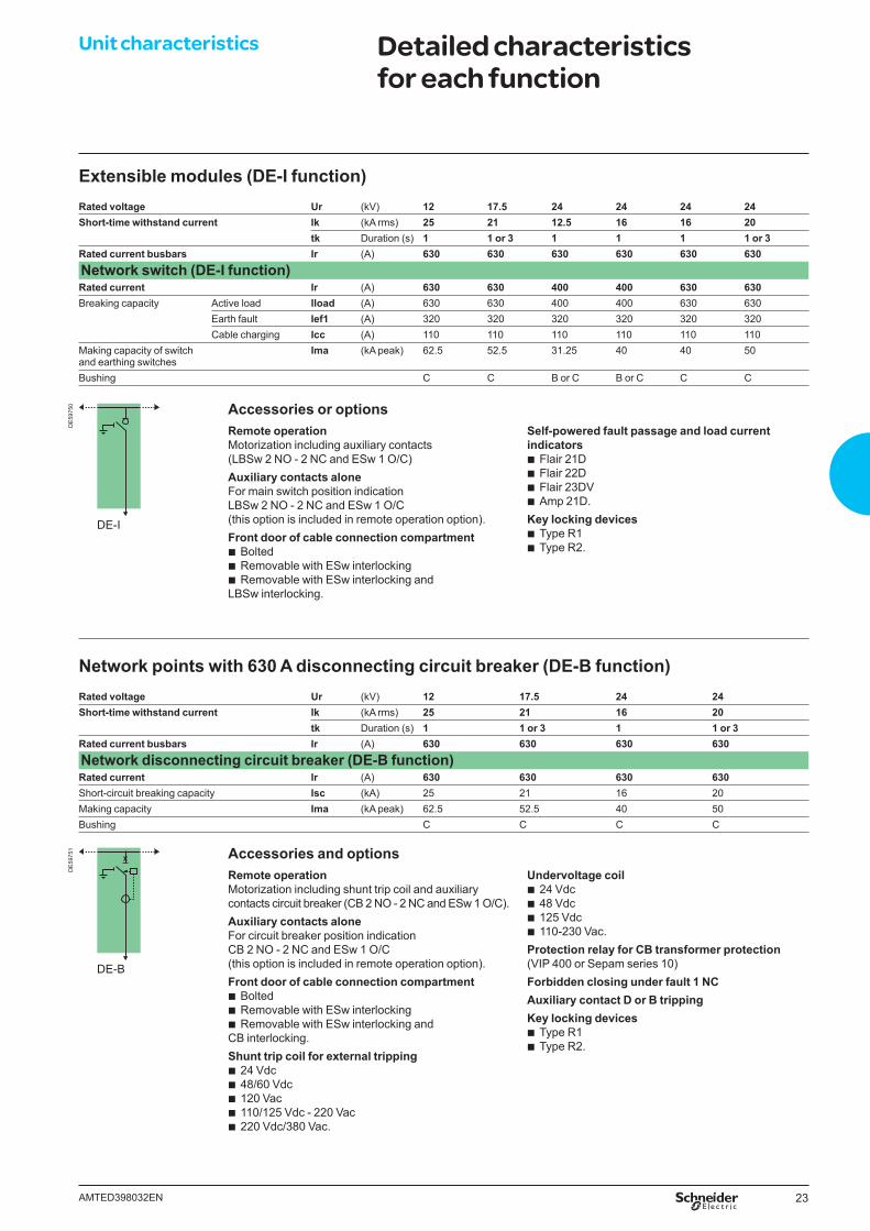
Extensible modules (DE-I function)Rated voltage Ur (kV) 12 17.5 24 24 24 24Short-time withstand current Ik (kA rms) 25 21 12.5 16 16 20
tk Duration (s) 1 1 or 3 1 1 1 1 or 3Rated current busbars Ir (A) 630 630 630 630 630 630Network switch (DE-I function)Rated current Ir (A) 630 630 400 400 630 630Breaking capacity Active load Iload (A) 630 630 400 400 630 630
Earth fault Ief1 (A) 320 320 320 320 320 320Cable charging Icc (A) 110 110 110 110 110 110
Making capacity of switchand earthing switches
Ima (kA peak) 62.5 52.5 31.25 40 40 50
Bushing C C B or C B or C C C
DE
5975
0
DE-I
Network points with 630 A disconnecting circuit breaker (DE-B function)Rated voltage Ur (kV) 12 17.5 24 24Short-time withstand current Ik (kA rms) 25 21 16 20
tk Duration (s) 1 1 or 3 1 1 or 3Rated current busbars Ir (A) 630 630 630 630Network disconnecting circuit breaker (DE-B function)Rated current Ir (A) 630 630 630 630Short-circuit breaking capacity Isc (kA) 25 21 16 20Making capacity Ima (kA peak) 62.5 52.5 40 50Bushing C C C C
DE
5975
1
DE-B
Remote operationMotorization including shunt trip coil and auxiliary contacts circuit breaker (CB 2 NO - 2 NC and ESw 1 O/C).Auxiliary contacts aloneFor circuit breaker position indication CB 2 NO - 2 NC and ESw 1 O/C(this option is included in remote operation option).Front door of cable connection compartment
b Bolted b Removable with ESw interlocking b Removable with ESw interlocking and
CB interlocking.Shunt trip coil for external tripping
b 24 Vdc b 48/60 Vdc b 120 Vac b 110/125 Vdc - 220 Vac b 220 Vdc/380 Vac.
Undervoltage coil b 24 Vdc b 48 Vdc b 125 Vdc b 110-230 Vac.
Protection relay for CB transformer protection (VIP 400 or Sepam series 10)Forbidden closing under fault 1 NC Auxiliary contact D or B trippingKey locking devices
b Type R1 b Type R2.
Accessories and options
Remote operationMotorization including auxiliary contacts (LBSw 2 NO - 2 NC and ESw 1 O/C)Auxiliary contacts aloneFor main switch position indication LBSw 2 NO - 2 NC and ESw 1 O/C(this option is included in remote operation option).Front door of cable connection compartment
b Bolted b Removable with ESw interlocking b Removable with ESw interlocking and
LBSw interlocking.
Self-powered fault passage and load current indicators
b Flair 21D b Flair 22D b Flair 23DV b Amp 21D.
Key locking devices b Type R1 b Type R2.
Accessories or options
Unit characteristics Detailed characteristics for each function
24 AMTED398032EN
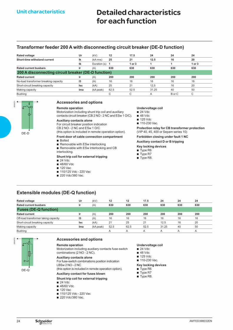
Transformer feeder 200 A with disconnecting circuit breaker (DE-D function)Rated voltage Ur (kV) 12 17.5 24 24 24Short-time withstand current Ik (kA rms) 25 21 12.5 16 20
tk Duration (s) 1 1 or 3 1 1 1 or 3Rated current busbars Ir (A) 630 630 630 630 630200 A disconnecting circuit breaker (DE-D function)Rated current Ir (A) 200 200 200 200 200No-load transformer breaking capacity I3 (A) 16 16 16 16 16Short-circuit breaking capacity Isc (kA) 25 21 12,5 16 20Making capacity Ima (kA peak) 62.5 52.5 31.25 40 50Bushing C C A B or C C
Extensible modules (DE-Q function)Rated voltage Ur (kV) 12 12 17.5 24 24 24Rated current busbars Ir (A) 630 630 630 630 630 630Fuses (DE-Q function)Rated current Ir (A) 200 200 200 200 200 200Off-load transformer laking capacity I3 (A) 16 16 16 16 16 16Short-circuit breaking capacity Isc (kA) 21 25 21 12.5 16 20Making capacity Ima (kA peak) 52.5 62.5 52.5 31.25 40 50Bushing A A A A A A
DE
5975
1
DE-D
Remote operationMotorization including auxiliary contacts fuse-switch combinations (2 NO - 2 NC).Auxiliary contacts aloneFor fuse-switch combinations position indication LBSw 2 NO - 2 NC(this option is included in remote operation option).Auxiliary contact for fuses blownShunt trip coil for external tripping
b 24 Vdc b 48/60 Vdc b 120 Vac b 110/125 Vdc - 220 Vac b 220 Vdc/380 Vac.
Undervoltage coil b 24 Vdc b 48 Vdc b 125 Vdc b 110-230 Vac.
Key locking devices b Type R6 b Type R7 b Type R8.
Accessories and options
Accessories and optionsRemote operationMotorization including shunt trip coil and auxiliary contacts circuit breaker (CB 2 NO - 2 NC and ESw 1 O/C).Auxiliary contacts aloneFor circuit breaker position indication CB 2 NO - 2 NC and ESw 1 O/C(this option is included in remote operation option).Front door of cable connection compartment
b Bolted b Removable with ESw interlocking b Removable with ESw interlocking and CB
interlocking.Shunt trip coil for external tripping
b 24 Vdc b 48/60 Vdc b 120 Vac b 110/125 Vdc - 220 Vac b 220 Vdc/380 Vac.
Undervoltage coil b 24 Vdc b 48 Vdc b 125 Vdc b 110-230 Vac.
Protection relay for CB transformer protection (VIP 40, 45, 400 or Sepam series 10)Forbidden closing under fault 1 NC Auxiliary contact D or B trippingKey locking devices
b Type R6 b Type R7 b Type R8.
DE
5975
3
DE-Q
Unit characteristics Detailed characteristics for each function
25AMTED398032EN
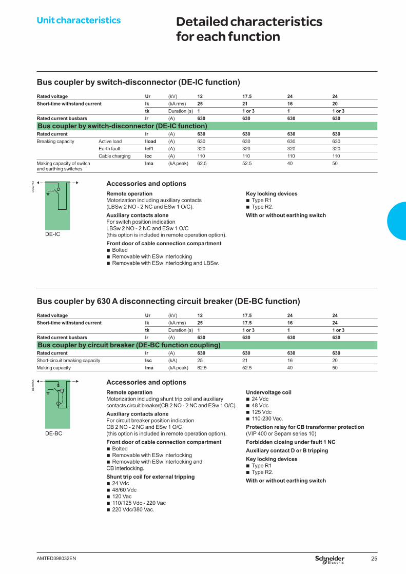
Bus coupler by switch-disconnector (DE-IC function)Rated voltage Ur (kV) 12 17.5 24 24Short-time withstand current Ik (kA rms) 25 21 16 20
tk Duration (s) 1 1 or 3 1 1 or 3Rated current busbars Ir (A) 630 630 630 630Bus coupler by switch-disconnector (DE-IC function)Rated current Ir (A) 630 630 630 630Breaking capacity Active load Iload (A) 630 630 630 630
Earth fault Ief1 (A) 320 320 320 320Cable charging Icc (A) 110 110 110 110
Making capacity of switchand earthing switches
Ima (kA peak) 62.5 52.5 40 50
DE
5975
4
DE-IC
Bus coupler by 630 A disconnecting circuit breaker (DE-BC function)Rated voltage Ur (kV) 12 17.5 24 24Short-time withstand current Ik (kA rms) 25 17.5 16 24
tk Duration (s) 1 1 or 3 1 1 or 3Rated current busbars Ir (A) 630 630 630 630Bus coupler by circuit breaker (DE-BC function coupling)Rated current Ir (A) 630 630 630 630Short-circuit breaking capacity Isc (kA) 25 21 16 20Making capacity Ima (kA peak) 62.5 52.5 40 50
DE
5975
5
DE-BC
Accessories and optionsRemote operationMotorization including auxiliary contacts (LBSw 2 NO - 2 NC and ESw 1 O/C).Auxiliary contacts aloneFor switch position indication LBSw 2 NO - 2 NC and ESw 1 O/C(this option is included in remote operation option).Front door of cable connection compartment
b Bolted b Removable with ESw interlocking b Removable with ESw interlocking and LBSw.
Key locking devices b Type R1 b Type R2.
With or without earthing switch
Accessories and optionsRemote operationMotorization including shunt trip coil and auxiliary contacts circuit breaker(CB 2 NO - 2 NC and ESw 1 O/C).Auxiliary contacts aloneFor circuit breaker position indication CB 2 NO - 2 NC and ESw 1 O/C(this option is included in remote operation option).Front door of cable connection compartment
b Bolted b Removable with ESw interlocking b Removable with ESw interlocking and
CB interlocking.Shunt trip coil for external tripping
b 24 Vdc b 48/60 Vdc b 120 Vac b 110/125 Vdc - 220 Vac b 220 Vdc/380 Vac.
Undervoltage coil b 24 Vdc b 48 Vdc b 125 Vdc b 110-230 Vac.
Protection relay for CB transformer protection(VIP 400 or Sepam series 10)Forbidden closing under fault 1 NC Auxiliary contact D or B tripping Key locking devices
b Type R1 b Type R2.
With or without earthing switch
Unit characteristics Detailed characteristics for each function
26 AMTED398032EN
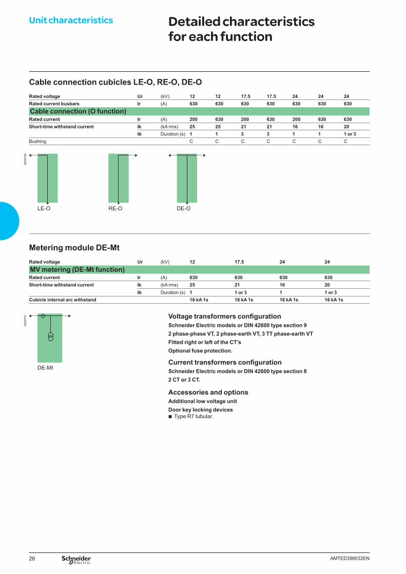
Cable connection cubicles LE-O, RE-O, DE-ORated voltage Ur (kV) 12 12 17.5 17.5 24 24 24Rated current busbars Ir (A) 630 630 630 630 630 630 630Cable connection (O function)Rated current Ir (A) 200 630 200 630 200 630 630Short-time withstand current Ik (kA rms) 25 25 21 21 16 16 20
tk Duration (s) 1 1 3 3 1 1 1 or 3Bushing C C C C C C C
DE
5975
6
LE-O RE-O DE-O
Metering module DE-MtRated voltage Ur (kV) 12 17.5 24 24MV metering (DE-Mt function)Rated current Ir (A) 630 630 630 630Short-time withstand current Ik (kA rms) 25 21 16 20
tk Duration (s) 1 1 or 3 1 1 or 3Cubicle internal arc withstand 16 kA 1s 16 kA 1s 16 kA 1s 16 kA 1s
Voltage transformers confi gurationSchneider Electric models or DIN 42600 type section 92 phase-phase VT, 2 phase-earth VT, 3 TT phase-earth VTFitted right or left of the CT’sOptional fuse protection.
Current transformers confi gurationSchneider Electric models or DIN 42600 type section 82 CT or 3 CT.
Accessories and options Additional low voltage unit Door key locking devices
b Type R7 tubular.
DE-Mt
DE
5975
7Unit characteristics Detailed characteristics
for each function
27AMTED398032EN
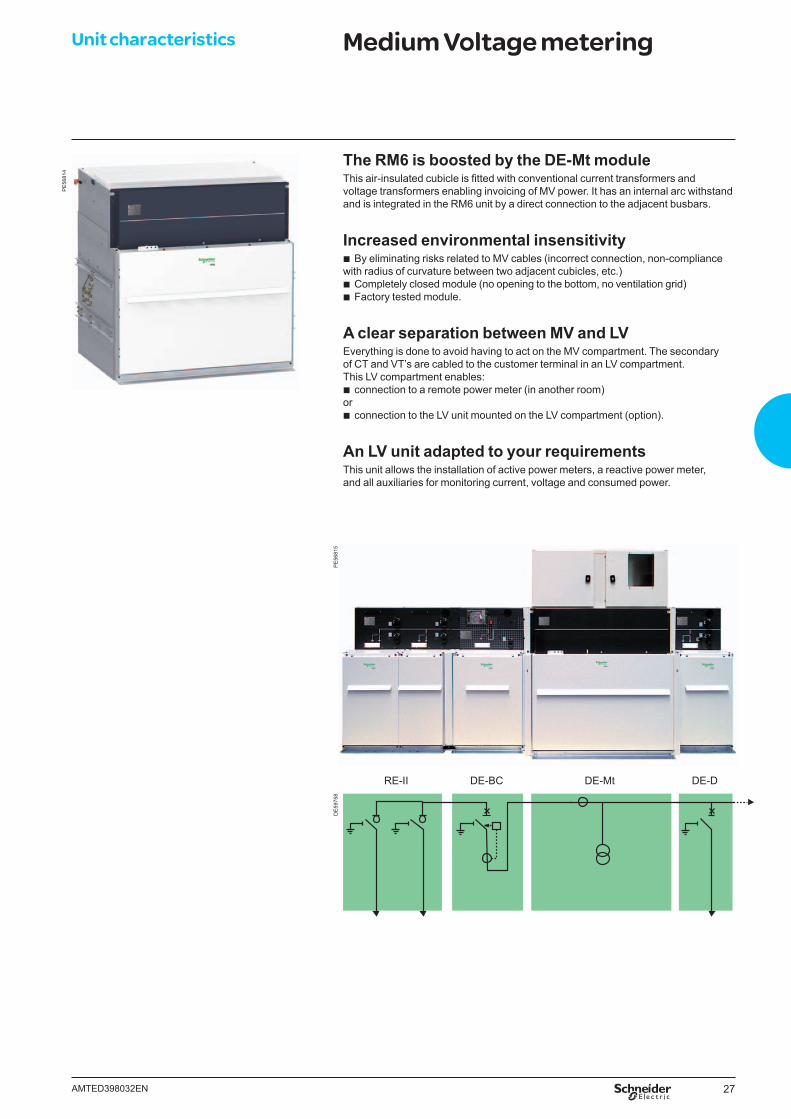
The RM6 is boosted by the DE-Mt moduleThis air-insulated cubicle is fi tted with conventional current transformers and voltage transformers enabling invoicing of MV power. It has an internal arc withstand and is integrated in the RM6 unit by a direct connection to the adjacent busbars.
Increased environmental insensitivity b By eliminating risks related to MV cables (incorrect connection, non-compliance
with radius of curvature between two adjacent cubicles, etc.) b Completely closed module (no opening to the bottom, no ventilation grid) b Factory tested module.
A clear separation between MV and LVEverything is done to avoid having to act on the MV compartment. The secondary of CT and VT’s are cabled to the customer terminal in an LV compartment. This LV compartment enables:
b connection to a remote power meter (in another room) or
b connection to the LV unit mounted on the LV compartment (option).
An LV unit adapted to your requirementsThis unit allows the installation of active power meters, a reactive power meter, and all auxiliaries for monitoring current, voltage and consumed power.
RE-II DE-BC DE-Mt DE-D
PE
5681
4
Unit characteristics Medium Voltage metering
DE
5975
8P
E56
815
28 AMTED398032EN
Unit characteristics RM6 Free CombinationConfiguration
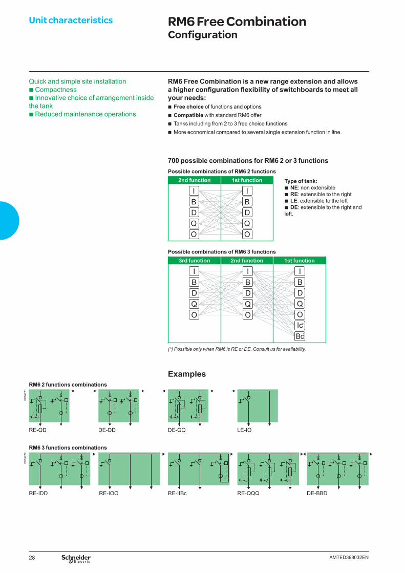
RM6 Free Combination is a new range extension and allows a higher confi guration fl exibility of switchboards to meet all your needs:
b Free choice of functions and options b Compatible with standard RM6 offer b Tanks including from 2 to 3 free choice functions b More economical compared to several single extension function in line.
700 possible combinations for RM6 2 or 3 functionsPossible combinations of RM6 2 functions
2nd function 1st function Type of tank: b NE: non extensible b RE: extensible to the right b LE: extensible to the left b DE: extensible to the right and
left.
IBDQO
IBDQO
Possible combinations of RM6 3 functions3rd function 2nd function 1st function
IBDQ
IcBc
O*
*
IBDQO
IBDQO
(*) Possible only when RM6 is RE or DE. Consult us for availability.
ExamplesRM6 2 functions combinations
DE
5977
1
RE-QD DE-DD DE-QQ LE-IO
RM6 3 functions combinations
DE
5977
2
RE-IDD RE-IOO RE-IIBc RE-QQQ DE-BBD
Quick and simple site installation b Compactnessb Innovative choice of arrangement inside the tankb Reduced maintenance operations
29AMTED398032EN
Unit characteristics RM6 Free CombinationApplications
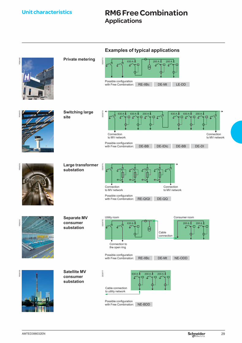
Examples of typical applications
PE
9016
0 Private metering
DE
5977
3
630 A 200 A 200 A
Possible confi guration with Free Combination: RE-IIBc DE-Mt LE-DD
PE
9007
5 Switching large site D
E59
774
630 A 630 A 200 A 630 A 630 A 200 A
Connection to MV network
Connection to MV network
Possible confi guration with Free Combination: DE-BB DE-IDIc DE-BB DE-DI
PE
9007
6 Large transformer substation D
E59
775
Connection to MV network
Connection to MV network
Possible confi guration with Free Combination: RE-QIQI DE-QQ
Separate MV consumer substation
Utility room Consumer room
PE
9021
0
DE
5977
6
630 A 200 A 200 A
Cableconnection
Connection to the open ring
Possible confi guration with Free Combination: RE-IIBc DE-Mt NE-ODD
PE
9015
9 Satellite MV consumer substation
DE
5977
7
200 A 200 A630 A
Cable connection to utility network
Possible confi guration with Free Combination: NE-BDD
30 AMTED398032EN
Unit characteristics RM6 5 functions *Configuration
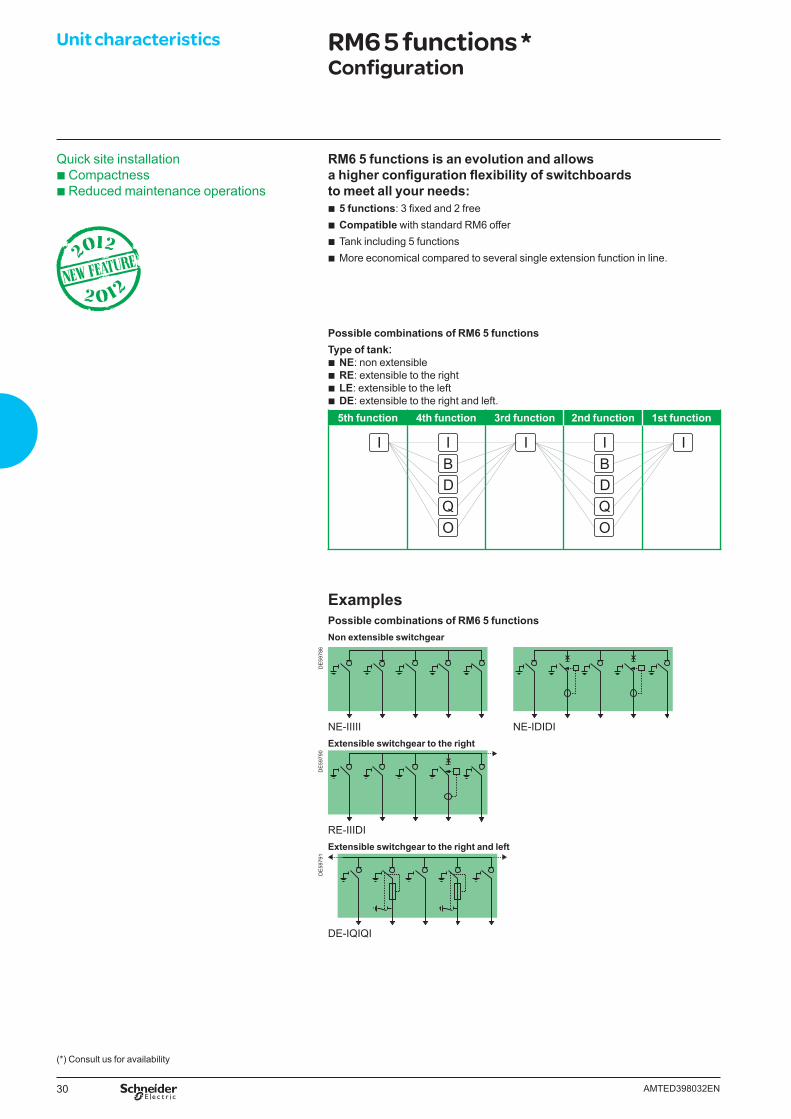
RM6 5 functions is an evolution and allows a higher confi guration fl exibility of switchboards to meet all your needs:
b 5 functions: 3 fi xed and 2 free b Compatible with standard RM6 offer b Tank including 5 functions b More economical compared to several single extension function in line.
Possible combinations of RM6 5 functionsType of tank:
b NE: non extensible b RE: extensible to the right b LE: extensible to the left b DE: extensible to the right and left.5th function 4th function 3rd function 2nd function 1st function
II IBDQO
IBDQO
I
ExamplesPossible combinations of RM6 5 functionsNon extensible switchgear
DE
5978
6
NE-IIIII NE-IDIDIExtensible switchgear to the right
DE
5979
0
RE-IIIDIExtensible switchgear to the right and left
DE
5979
1
DE-IQIQI
Quick site installation b Compactnessb Reduced maintenance operations
(*) Consult us for availability
31AMTED398032EN
Unit characteristics Circuit breaker functionProtection relays selection
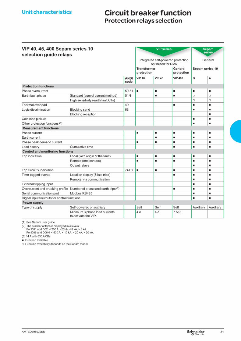
VIP 40, 45, 400 Sepam series 10 selection guide relays
VIP series
Integrated self-powered protectionoptimised for RM6
Sepam series
General
Transformerprotection
Generalprotection
Sepam series 10
ANSI code
VIP 40 VIP 45 VIP 400 B A
Protection functionsPhase overcurrent 50-51 b b b b b
Earth fault phase Standard (sum of current method) 51N b b v v
High sensitivity (earth fault CTs) v v
Thermal overload 49 b b b
Logic discrimination Blocking send 68 b b
Blocking reception b
Cold load pick-up b b
Other protection functions (1) b b
Measurement functionsPhase current b b b b b
Earth current b b b b
Phase peak demand current b b b b b
Load history Cumulative time b b b
Control and monitoring functionsTrip indication Local (with origin of the fault) b b b b b
Remote (one contact) b b b b b
Output relays b b
Trip circuit supervision 74TC b b b b b
Time-tagged events Local on display (5 last trips) b b b
Remote, via communication b b
External tripping input b b
Overcurrent and breaking profi le Number of phase and earth trips (2) b b b
Serial communication port Modbus RS485 b b
Digital inputs/outputs for control functions b b
Power supplyType of supply Self-powered or auxiliary Self Self Self Auxiliary Auxiliary
Minimum 3 phase load currents to activate the VIP
4 A 4 A 7 A (3)
(1) See Sepam user guide.(2) The number of trips is displayed in 4 levels: For D01 and D02: < 200 A, < 2 kA, < 8 kA, > 8 kA For D06 and D06H: < 630 A, < 10 kA, < 20 kA, > 20 kA.(3) 14 A with 630 A CBs
b Function available v Function availability depends on the Sepam model.
32 AMTED398032EN
Unit characteristics Transformer protection by circuit breaker VIP 40, VIP 45
Application b Entry level MV/LV transformer protection b Dependent-time phase overcurrent tripping curve dedicated to MV/LV transformer
protection b Defi nite-time earth fault protection b Phase current and peak demand current measurement.
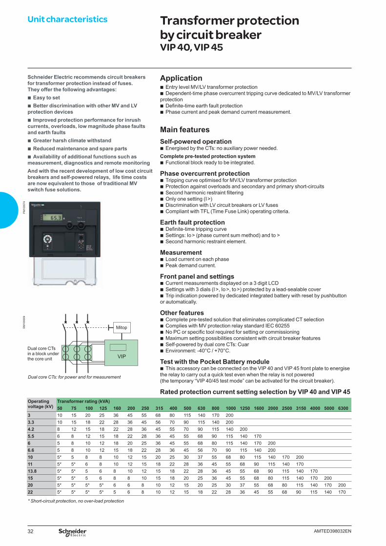
Main featuresSelf-powered operation
b Energised by the CTs: no auxiliary power needed.Complete pre-tested protection system
b Functional block ready to be integrated.
Phase overcurrent protection b Tripping curve optimised for MV/LV transformer protection b Protection against overloads and secondary and primary short-circuits b Second harmonic restraint fi ltering b Only one setting (I >) b Discrimination with LV circuit breakers or LV fuses b Compliant with TFL (Time Fuse Link) operating criteria.
Earth fault protection b Defi nite-time tripping curve b Settings: Io > (phase current sum method) and to > b Second harmonic restraint element.
Measurement b Load current on each phase b Peak demand current.
Front panel and settings b Current measurements displayed on a 3 digit LCD b Settings with 3 dials (I >, Io >, to >) protected by a lead-sealable cover b Trip indication powered by dedicated integrated battery with reset by pushbutton
or automatically.
Other features b Complete pre-tested solution that eliminates complicated CT selection b Complies with MV protection relay standard IEC 60255 b No PC or specifi c tool required for setting or commissioning b Maximum setting possibilities consistent with circuit breaker features b Self-powered by dual core CTs: Cuar b Environment: -40°C / +70°C.
Test with the Pocket Battery module b This accessory can be connected on the VIP 40 and VIP 45 front plate to energise
the relay to carry out a quick test even when the relay is not powered (the temporary “VIP 40/45 test mode” can be activated for the circuit breaker).
Rated protection current setting selection by VIP 40 and VIP 45Operating voltage (kV)
Transformer rating (kVA)50 75 100 125 160 200 250 315 400 500 630 800 1000 1250 1600 2000 2500 3150 4000 5000 6300
3 10 15 20 25 36 45 55 68 80 115 140 170 2003.3 10 15 18 22 28 36 45 56 70 90 115 140 2004.2 8 12 15 18 22 28 36 45 55 70 90 115 140 2005.5 6 8 12 15 18 22 28 36 45 55 68 90 115 140 1706 5 8 10 12 18 20 25 36 45 55 68 80 115 140 170 2006.6 5 8 10 12 15 18 22 28 36 45 56 70 90 115 140 20010 5* 5 8 8 10 12 15 20 25 30 37 55 68 80 115 140 170 20011 5* 5* 6 8 10 12 15 18 22 28 36 45 55 68 90 115 140 17013.8 5* 5* 5 6 8 10 12 15 18 22 28 36 45 55 68 90 115 140 17015 5* 5* 5 6 8 8 10 15 18 20 25 36 45 55 68 80 115 140 170 20020 5* 5* 5* 5* 6 6 8 10 12 15 20 25 30 37 55 68 80 115 140 170 20022 5* 5* 5* 5* 5 6 8 10 12 15 18 22 28 36 45 55 68 90 115 140 170
* Short-circuit protection, no over-load protection
Dual core CTsin a block under the core unit
Schneider Electric recommends circuit breakers for transformer protection instead of fuses. They offer the following advantages:
b Easy to set b Better discrimination with other MV and LV
protection devices b Improved protection performance for inrush
currents, overloads, low magnitude phase faults and earth faults
b Greater harsh climate withstand b Reduced maintenance and spare parts b Availability of additional functions such as
measurement, diagnostics and remote monitoringAnd with the recent development of low cost circuit breakers and self-powered relays, life time costs are now equivalent to those of traditional MV switch fuse solutions.
Dual core CTs: for power and for measurement
Mitop
VIP
DM
1000
09P
M10
0574
33AMTED398032EN
Unit characteristics General protection by circuit breaker VIP 400
Applications b MV distribution substation incomer or feeder protection relay b MV/LV transformer protection.
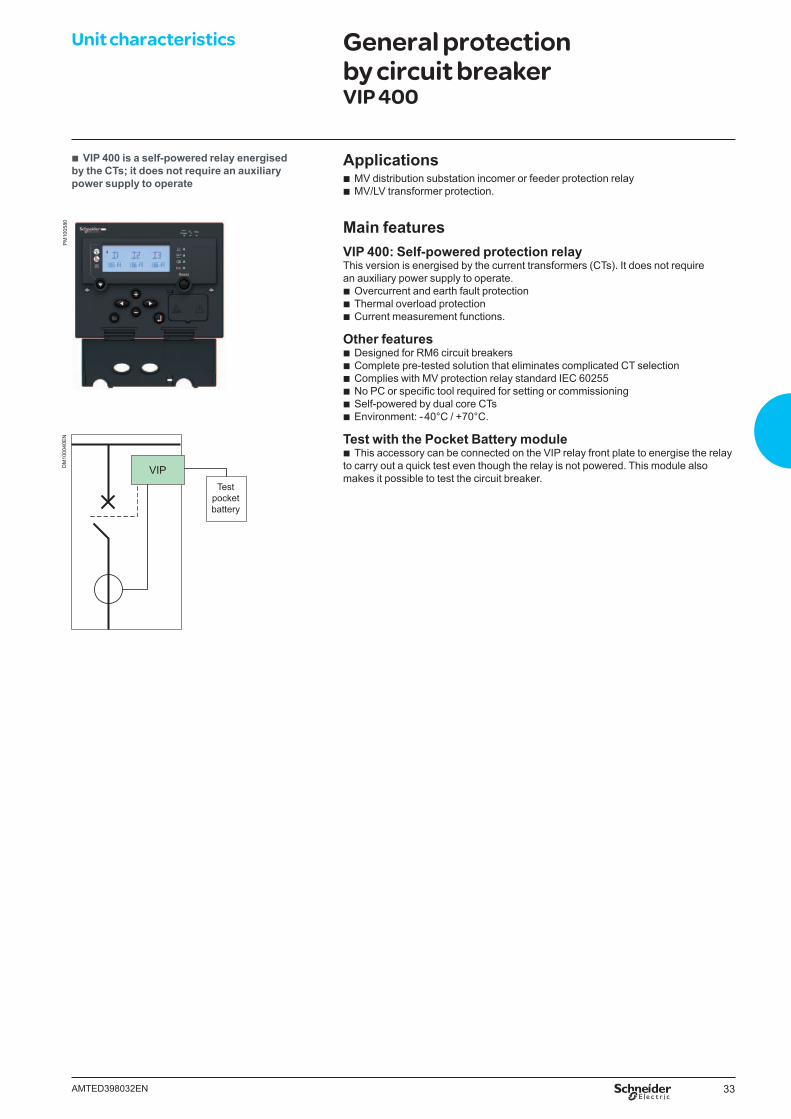
Main featuresVIP 400: Self-powered protection relayThis version is energised by the current transformers (CTs). It does not require an auxiliary power supply to operate.
b Overcurrent and earth fault protection b Thermal overload protection b Current measurement functions.
Other features b Designed for RM6 circuit breakers b Complete pre-tested solution that eliminates complicated CT selection b Complies with MV protection relay standard IEC 60255 b No PC or specifi c tool required for setting or commissioning b Self-powered by dual core CTs b Environment: - 40°C / +70°C.
Test with the Pocket Battery module b This accessory can be connected on the VIP relay front plate to energise the relay
to carry out a quick test even though the relay is not powered. This module also makes it possible to test the circuit breaker.
b VIP 400 is a self-powered relay energised by the CTs; it does not require an auxiliary power supply to operate
PM
1005
80D
M10
0040
EN
VIPTest
pocketbattery
34 AMTED398032EN
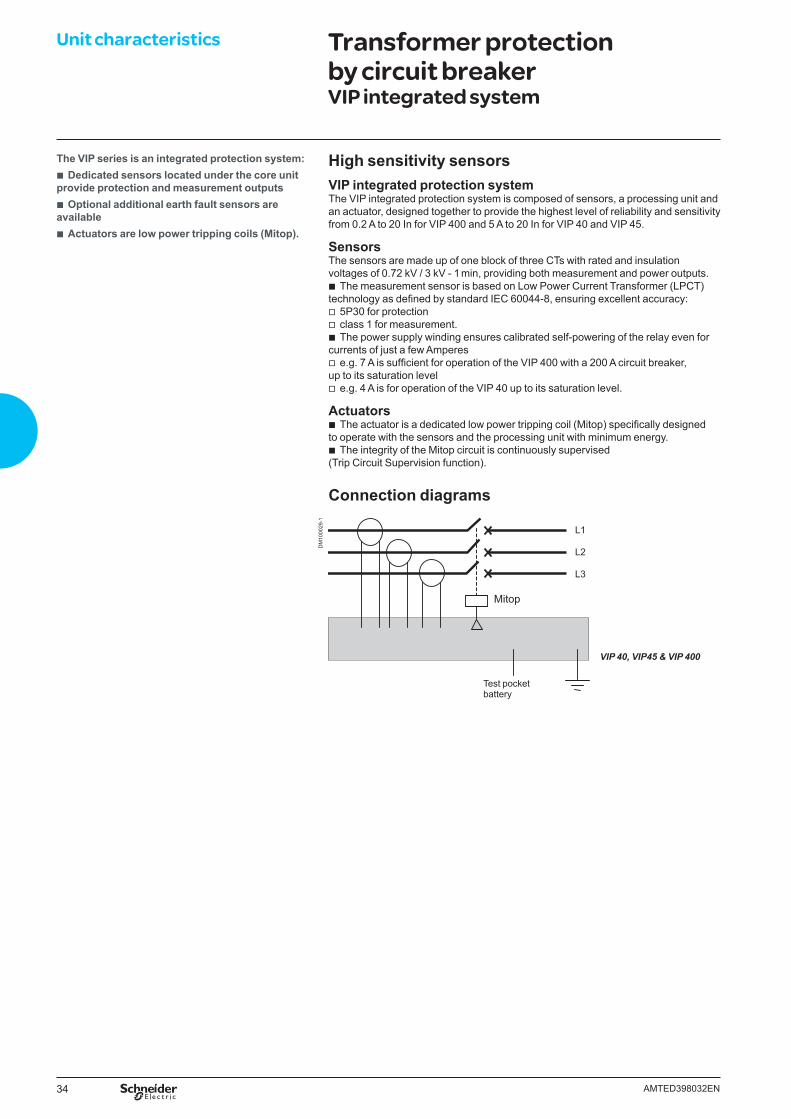
Unit characteristics Transformer protection by circuit breaker VIP integrated system
High sensitivity sensorsVIP integrated protection systemThe VIP integrated protection system is composed of sensors, a processing unit and an actuator, designed together to provide the highest level of reliability and sensitivity from 0.2 A to 20 In for VIP 400 and 5 A to 20 In for VIP 40 and VIP 45.
SensorsThe sensors are made up of one block of three CTs with rated and insulation voltages of 0.72 kV / 3 kV - 1 min, providing both measurement and power outputs.
b The measurement sensor is based on Low Power Current Transformer (LPCT) technology as defi ned by standard IEC 60044-8, ensuring excellent accuracy:
v 5P30 for protection v class 1 for measurement. b The power supply winding ensures calibrated self-powering of the relay even for
currents of just a few Amperes v e.g. 7 A is suffi cient for operation of the VIP 400 with a 200 A circuit breaker,
up to its saturation level v e.g. 4 A is for operation of the VIP 40 up to its saturation level.
Actuators b The actuator is a dedicated low power tripping coil (Mitop) specifi cally designed
to operate with the sensors and the processing unit with minimum energy. b The integrity of the Mitop circuit is continuously supervised
(Trip Circuit Supervision function).
Connection diagrams
VIP 40, VIP45 & VIP 400
The VIP series is an integrated protection system: b Dedicated sensors located under the core unit
provide protection and measurement outputs b Optional additional earth fault sensors are
available b Actuators are low power tripping coils (Mitop).
DM
1000
29-1
Mitop
L1
L2
L3
Test pocketbattery
35AMTED398032EN
ABC
DE
5978
7
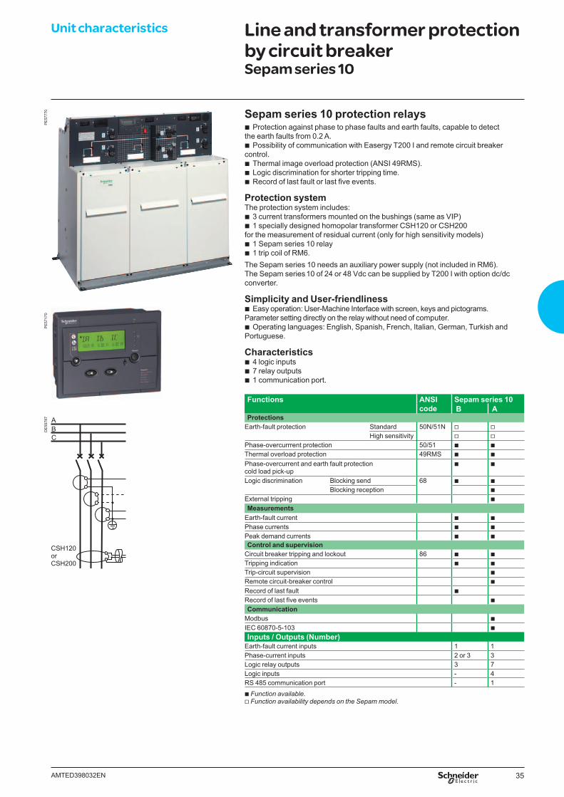
Unit characteristics Line and transformer protection by circuit breakerSepam series 10
Functions ANSI code
Sepam series 10 B A
ProtectionsEarth-fault protection Standard 50N/51N v v
High sensitivity v vPhase-overcurrrent protection 50/51 b bThermal overload protection 49RMS b b
Phase-overcurrent and earth fault protection cold load pick-up
b b
Logic discrimination Blocking send 68 b bBlocking reception b
External tripping bMeasurements
Earth-fault current b bPhase currents b bPeak demand currents b bControl and supervision
Circuit breaker tripping and lockout 86 b bTripping indication b bTrip-circuit supervision bRemote circuit-breaker control bRecord of last fault bRecord of last fi ve events bCommunication
Modbus bIEC 60870-5-103 b
Inputs / Outputs (Number)Earth-fault current inputs 1 1Phase-current inputs 2 or 3 3Logic relay outputs 3 7Logic inputs - 4RS 485 communication port - 1 b Function available.v Function availability depends on the Sepam model.
Sepam series 10 protection relays b Protection against phase to phase faults and earth faults, capable to detect
the earth faults from 0.2 A. b Possibility of communication with Easergy T200 I and remote circuit breaker
control. b Thermal image overload protection (ANSI 49RMS). b Logic discrimination for shorter tripping time. b Record of last fault or last fi ve events.
Protection systemThe protection system includes:
b 3 current transformers mounted on the bushings (same as VIP) b 1 specially designed homopolar transformer CSH120 or CSH200
for the measurement of residual current (only for high sensitivity models) b 1 Sepam series 10 relay b 1 trip coil of RM6.
The Sepam series 10 needs an auxiliary power supply (not included in RM6).The Sepam series 10 of 24 or 48 Vdc can be supplied by T200 I with option dc/dc converter.
Simplicity and User-friendliness b Easy operation: User-Machine Interface with screen, keys and pictograms.
Parameter setting directly on the relay without need of computer. b Operating languages: English, Spanish, French, Italian, German, Turkish and
Portuguese.
Characteristics b 4 logic inputs b 7 relay outputs b 1 communication port.
PE
5777
0P
E57
170
CSH120 or CSH200
36 AMTED398032EN
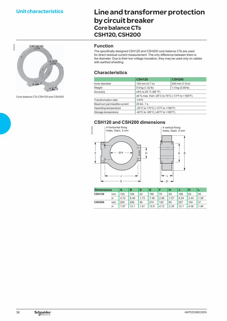
Unit characteristics Line and transformer protection by circuit breakerCore balance CTs CSH120, CSH200
FunctionThe specifi cally designed CSH120 and CSH200 core balance CTs are used for direct residual current measurement. The only difference between them is the diameter. Due to their low voltage insulation, they may be used only on cables with earthed shielding.
CharacteristicsCSH120 CSH200
Inner diameter 120 mm (4.7 in) 200 mm (7.9 in)Weight 0.6 kg (1.32 lb) 1.4 kg (3.09 lb)Accuracy ±5% to 20 °C (68 °F)
±6 % max. from -25°C to 70°C (-13°F to +158°F) Transformation ratio 1/470Maximum permissible current 20 kA - 1 sOperating temperature -25°C to +70°C (-13°F to +158°F)Storage temperature -40°C to +85°C (-40°F to +185°F)
CSH120 and CSH200 dimensions
DE
5344
6EN 4 horizontal fixing
holes, Diam. 5 mm4 vertical fixingholes, Diam. 5 mm
Dimensions A B D E F H J K LCSH120 mm 120 164 44 190 76 40 166 62 35
in 4.72 6.46 1.73 7.48 2.99 1.57 6.54 2.44 1.38CSH200 mm 200 256 46 274 120 60 257 104 37
in 7.87 10.1 1.81 10.8 4.72 2.36 10.1 4.09 1.46
PE
5003
2
Core balance CTs CSH120 and CSH200
37AMTED398032EN
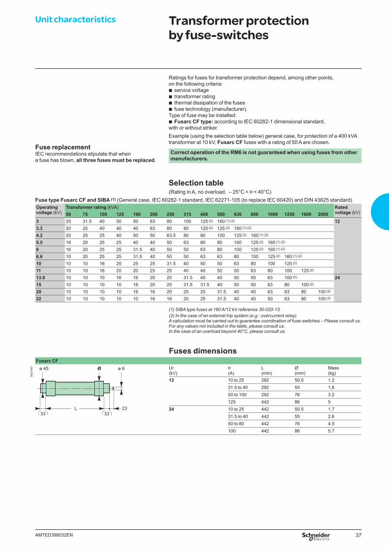
Ratings for fuses for transformer protection depend, among other points, on the following criteria:
b service voltage b transformer rating b thermal dissipation of the fuses b fuse technology (manufacturer).
Type of fuse may be installed: b Fusarc CF type: according to IEC 60282-1 dimensional standard,
with or without striker.Example (using the selection table below) general case, for protection of a 400 kVA transformer at 10 kV, Fusarc CF fuses with a rating of 50 A are chosen.
Correct operation of the RM6 is not guaranteed when using fuses from other manufacturers.
Selection table(Rating in A, no overload, – 25°C < θ < 40°C)
Fuse type Fusarc CF and SIBA (1) (General case, IEC 60282-1 standard, IEC 62271-105 (to replace IEC 60420) and DIN 43625 standard)Operating voltage (kV)
Transformer rating (kVA) Rated voltage (kV)50 75 100 125 160 200 250 315 400 500 630 800 1000 1250 1600 2000
3 20 31.5 40 50 50 63 80 100 125 (2) 160 (1) (2) 123.3 20 25 40 40 40 63 80 80 125 (2) 125 (2) 160 (1) (2)
4.2 20 25 25 40 50 50 63.5 80 80 100 125 (2) 160 (1) (2)
5.5 16 20 25 25 40 40 50 63 80 80 100 125 (2) 160 (1) (2)
6 16 20 25 25 31.5 40 50 50 63 80 100 125 (2) 160 (1) (2)
6.6 10 20 25 25 31.5 40 50 50 63 63 80 100 125 (2) 160 (1) (2)
10 10 10 16 20 25 25 31.5 40 50 50 63 80 100 125 (2)
11 10 10 16 20 20 25 25 40 40 50 50 63 80 100 125 (2)
13.8 10 10 10 16 16 20 25 31.5 40 40 50 50 63 100 (2) 2415 10 10 10 10 16 20 25 31.5 31.5 40 50 50 63 80 100 (2)
20 10 10 10 10 16 16 20 25 25 31.5 40 40 63 63 80 100 (2)
22 10 10 10 10 10 16 16 20 25 31.5 40 40 50 63 80 100 (2)
Fuses dimensionsFusarc CF
DE
5746
7 ø 6ø 45 Ø
33L 23
33
Ur (kV)
Ir(A)
L(mm)
Ø(mm)
Mass(kg)
12 10 to 25 292 50.5 1.231.5 to 40 292 55 1,850 to 100 292 76 3.2125 442 86 5
24 10 to 25 442 50.5 1.731.5 to 40 442 55 2.650 to 80 442 76 4.5100 442 86 5.7
(1) SIBA type fuses at 160 A/12 kV reference 30-020-13.(2) In the case of an external trip system (e.g.: overcurrent relay)A calculation must be carried out to guarantee coordination of fuse-switches – Please consult us.For any values not included in the table, please consult us.In the case of an overload beyond 40°C, please consult us.
Fuse replacementIEC recommendations stipulate that when a fuse has blown, all three fuses must be replaced.
Unit characteristics Transformer protection by fuse-switches

38 AMTED398032EN.indd
39AMTED398032EN
Network remote control Contents
Architecture and SCADA L500 40
Easergy T200 I control unit 41
Automatic transfer systems 42
Motorization 46
40 AMTED398032EN
DE
5799
5
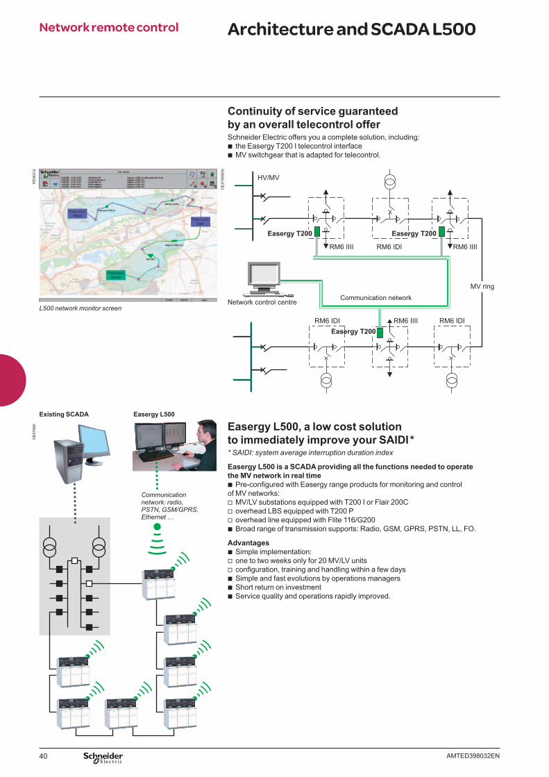
Continuity of service guaranteedby an overall telecontrol offerSchneider Electric offers you a complete solution, including:
b the Easergy T200 I telecontrol interface b MV switchgear that is adapted for telecontrol.
Easergy L500, a low cost solution to immediately improve your SAIDI ** SAIDI: system average interruption duration index
Easergy L500 is a SCADA providing all the functions needed to operate the MV network in real time
b Pre-confi gured with Easergy range products for monitoring and control of MV networks:
v MV/LV substations equipped with T200 I or Flair 200C v overhead LBS equipped with T200 P v overhead line equipped with Flite 116/G200 b Broad range of transmission supports: Radio, GSM, GPRS, PSTN, LL, FO.
Advantages b Simple implementation: v one to two weeks only for 20 MV/LV units v confi guration, training and handling within a few days b Simple and fast evolutions by operations managers b Short return on investment b Service quality and operations rapidly improved.
DE
5795
9EN
Network control centre
HV/MV
Communication network
RM6 IIII RM6 IDI RM6 IIII
RM6 IIIIRM6 IDI
Easergy T200
Easergy T200
Easergy T200
RM6 IDI
MV ring
Network remote control Architecture and SCADA L500
Communication network: radio, PSTN, GSM/GPRS, Ethernet …
Easergy L500Existing SCADA
PE
5631
2
L500 network monitor screen
41AMTED398032EN
PE
5631
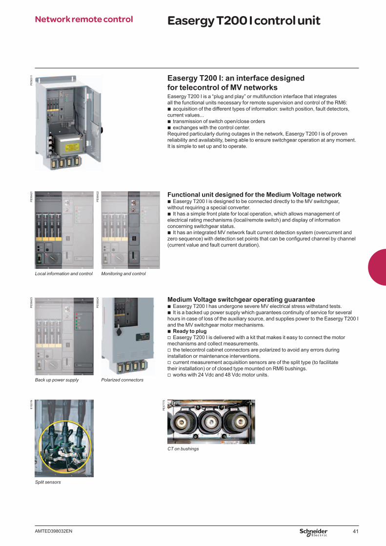
1 Easergy T200 I: an interface designedfor telecontrol of MV networksEasergy T200 I is a “plug and play” or multifunction interface that integrates all the functional units necessary for remote supervision and control of the RM6:
b acquisition of the different types of information: switch position, fault detectors, current values...
b transmission of switch open/close orders b exchanges with the control center.
Required particularly during outages in the network, Easergy T200 I is of proven reliability and availability, being able to ensure switchgear operation at any moment.It is simple to set up and to operate.
Functional unit designed for the Medium Voltage network b Easergy T200 I is designed to be connected directly to the MV switchgear,
without requiring a special converter. b It has a simple front plate for local operation, which allows management of
electrical rating mechanisms (local/remote switch) and display of information concerning switchgear status.
b It has an integrated MV network fault current detection system (overcurrent and zero sequence) with detection set points that can be confi gured channel by channel (current value and fault current duration).
Medium Voltage switchgear operating guarantee b Easergy T200 I has undergone severe MV electrical stress withstand tests. b It is a backed up power supply which guarantees continuity of service for several
hours in case of loss of the auxiliary source, and supplies power to the Easergy T200 I and the MV switchgear motor mechanisms.
b Ready to plug v Easergy T200 I is delivered with a kit that makes it easy to connect the motor
mechanisms and collect measurements. v the telecontrol cabinet connectors are polarized to avoid any errors during
installation or maintenance interventions. v current measurement acquisition sensors are of the split type (to facilitate
their installation) or of closed type mounted on RM6 bushings. v works with 24 Vdc and 48 Vdc motor units.
Split sensors
6102
1N
Local information and control Monitoring and control
Back up power supply Polarized connectors
PE
5642
1
PE
5642
2
PE
5642
3
PE
5682
4
Network remote control Easergy T200 I control unit
CT on bushings
PE
5777
5
42 AMTED398032EN
Network remote control Automatic transfer systems
PE
5777
1
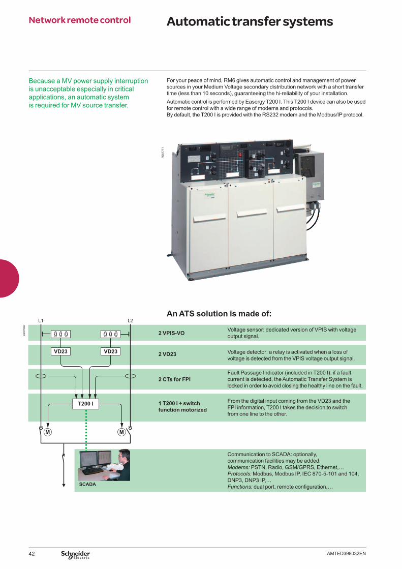
For your peace of mind, RM6 gives automatic control and management of power sources in your Medium Voltage secondary distribution network with a short transfer time (less than 10 seconds), guaranteeing the hi-reliability of your installation. Automatic control is performed by Easergy T200 I. This T200 I device can also be used for remote control with a wide range of modems and protocols. By default, the T200 I is provided with the RS232 modem and the Modbus/IP protocol.
An ATS solution is made of:
M M
SCADA
T200 I
VD23
L1 L2
VD23
2 VPIS-VO Voltage sensor: dedicated version of VPIS with voltage output signal.
2 VD23 Voltage detector: a relay is activated when a loss of voltage is detected from the VPIS voltage output signal.
2 CTs for FPIFault Passage Indicator (included in T200 I): if a fault current is detected, the Automatic Transfer System is locked in order to avoid closing the healthy line on the fault.
1 T200 I + switch function motorized
From the digital input coming from the VD23 and the FPI information, T200 I takes the decision to switch from one line to the other.
Communication to SCADA: optionally, communication facilities may be added.Modems: PSTN, Radio, GSM/GPRS, Ethernet,…Protocols: Modbus, Modbus IP, IEC 870-5-101 and 104, DNP3, DNP3 IP,… Functions: dual port, remote confi guration,…
DE
5799
2
Because a MV power supply interruption is unacceptable especially in critical applications, an automatic system is required for MV source transfer.
43AMTED398032EN
Network remote control Automatic transfer systems
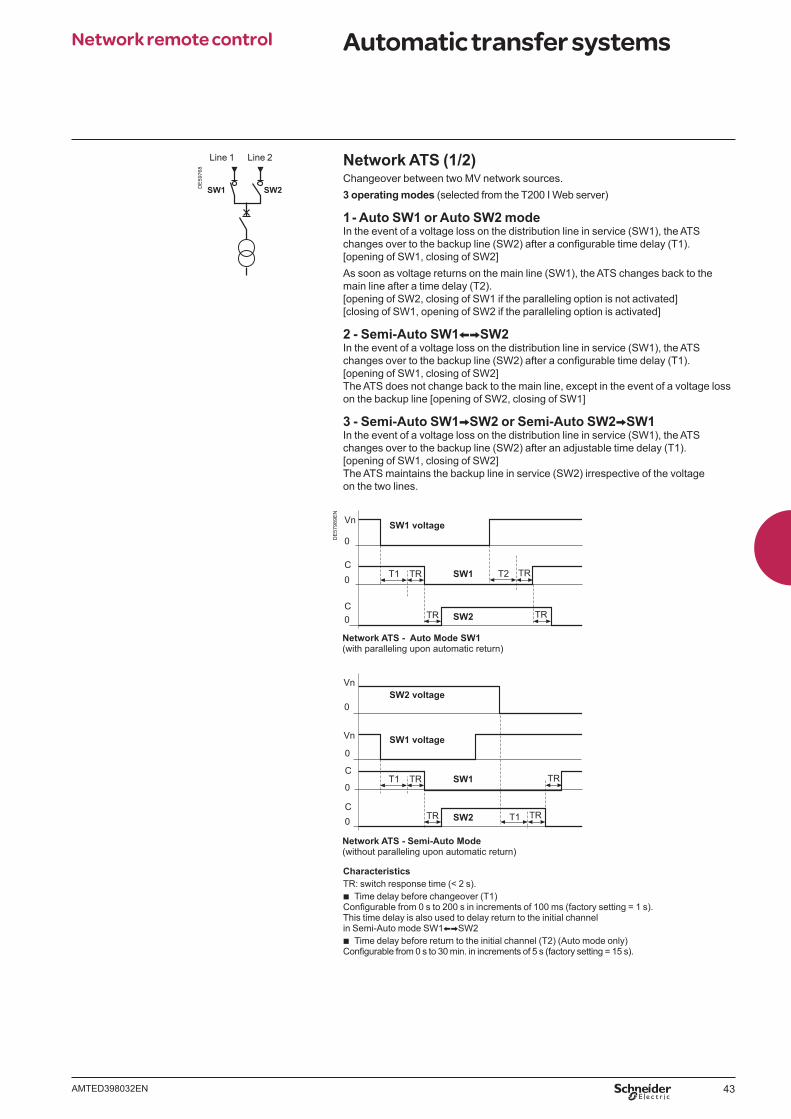
Network ATS (1/2)Changeover between two MV network sources.3 operating modes (selected from the T200 I Web server)
1 - Auto SW1 or Auto SW2 modeIn the event of a voltage loss on the distribution line in service (SW1), the ATS changes over to the backup line (SW2) after a confi gurable time delay (T1). [opening of SW1, closing of SW2]As soon as voltage returns on the main line (SW1), the ATS changes back to the main line after a time delay (T2). [opening of SW2, closing of SW1 if the paralleling option is not activated][closing of SW1, opening of SW2 if the paralleling option is activated]
2 - Semi-Auto SW1XVSW2In the event of a voltage loss on the distribution line in service (SW1), the ATS changes over to the backup line (SW2) after a confi gurable time delay (T1). [opening of SW1, closing of SW2]The ATS does not change back to the main line, except in the event of a voltage loss on the backup line [opening of SW2, closing of SW1]
3 - Semi-Auto SW1VSW2 or Semi-Auto SW2VSW1In the event of a voltage loss on the distribution line in service (SW1), the ATS changes over to the backup line (SW2) after an adjustable time delay (T1). [opening of SW1, closing of SW2]The ATS maintains the backup line in service (SW2) irrespective of the voltage on the two lines.
SW1 SW2DE
5976
8
Line 1 Line 2
DE
5798
9EN
CharacteristicsTR: switch response time (< 2 s).
b Time delay before changeover (T1) Confi gurable from 0 s to 200 s in increments of 100 ms (factory setting = 1 s).This time delay is also used to delay return to the initial channel in Semi-Auto mode SW1XVSW2
b Time delay before return to the initial channel (T2) (Auto mode only)Confi gurable from 0 s to 30 min. in increments of 5 s (factory setting = 15 s).
SW2 voltage
SW1 voltage
SW1 voltage
Network ATS - Auto Mode SW1(with paralleling upon automatic return)
Network ATS - Semi-Auto Mode (without paralleling upon automatic return)
T1
Vn
SW1
SW2 TR
Vn
Vn
0
0
C0
C0
0
C0
0
C
T1 T2
TR
SW2 TRTR
TR TR
SW1T1 TR TR
44 AMTED398032EN
Network remote control Automatic transfer systems
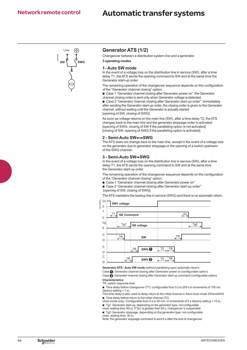
Generator ATS (1/2)Changeover between a distribution system line and a generator.3 operating modes
1 - Auto SW modeIn the event of a voltage loss on the distribution line in service (SW), after a time delay T1, the ATS sends the opening command to SW and at the same time the Generator start-up order.The remaining operation of the changeover sequence depends on the confi guration of the “Generator channel closing” option:
b Case 1 “Generator channel closing after Generator power on”: the Generator channel closing order is sent only when Generator voltage is detected.
b Case 2 “Generator channel closing after Generator start-up order”: immediately after sending the Generator start-up order, the closing order is given to the Generator channel, without waiting until the Generator is actually started.[opening of SW, closing of SWG]As soon as voltage returns on the main line (SW), after a time delay T2, the ATS changes back to the main line and the generator stoppage order is activated.[opening of SWG, closing of SW if the paralleling option is not activated][closing of SW, opening of SWG if the paralleling option is activated]
2 - Semi-Auto SWXVSWGThe ATS does not change back to the main line, except in the event of a voltage loss on the generator due to generator stoppage or the opening of a switch upstream of the SWG channel.
3 - Semi-Auto SWVSWGIn the event of a voltage loss on the distribution line in service (SW), after a time delay T1, the ATS sends the opening command to SW and at the same time the Generator start-up order.The remaining operation of the changeover sequence depends on the confi guration of the “Generator channel closing” option:
b Case 1 “Generator channel closing after Generator power on” b Case 2 “Generator channel closing after Generator start-up order”
[opening of SW, closing of SWG]The ATS maintains the backup line in service (SWG) and there is no automatic return.
DE
5799
8EN
SW1 voltage
GE Command
GE voltageTg1
Vn
01
0
Vg
0Tg2
T1 6s
TRTR
TRC
O
T2
TRT2
TR
C
OC
O
TR SWG
SW
SWG
Generator ATS - Auto SW mode (without paralleling upon automatic return)Case : Generator channel closing after Generator power on (confi gurable option)Case : Generator channel closing after Generator start-up command (confi gurable option)CharacteristicsTR: switch response time
b Time delay before changeover (T1): confi gurable from 0 s to 200 s in increments of 100 ms (factory setting = 1 s).This time delay is also used to delay return to the initial channel in Semi-Auto mode SWXVSWG
b Time delay before return to the initial channel (T2)(Auto mode only). Confi gurable from 0 s to 30 min. in increments of 5 s (factory setting = 15 s).
b Tg1: Generator start-up, depending on the generator type, not confi gurable (max. waiting time: 60 s). If Tg1 is greater than 60 s, changeover is suspended.
b Tg2: Generator stoppage, depending on the generator type, not confi gurable (max. waiting time: 30 s). Note: the generator stoppage command is sent 6 s after the end of changeover.
DE
5976
9
Line
SW SWG
G
45AMTED398032EN
Network remote control Automatic transfer systems
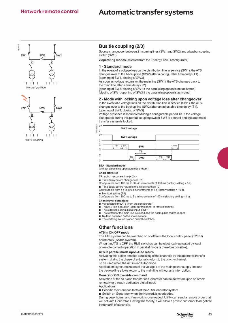
Bus tie coupling (2/3)Source changeover between 2 incoming lines (SW1 and SW2) and a busbar coupling switch (SW3).2 operating modes (selected from the Easergy T200 I confi gurator)
1 - Standard modeIn the event of a voltage loss on the distribution line in service (SW1), the ATS changes over to the backup line (SW2) after a confi gurable time delay (T1).[opening of SW1, closing of SW3]As soon as voltage returns on the main line (SW1), the ATS changes back to the main line after a time delay (T2).[opening of SW3, closing of SW1 if the paralleling option is not activated][closing of SW1, opening of SW3 if the paralleling option is activated]
2 - Mode with locking upon voltage loss after changeoverIn the event of a voltage loss on the distribution line in service (SW1), the ATS changes over to the backup line (SW2) after an adjustable time delay (T1).[opening of SW1, closing of SW3]Voltage presence is monitored during a confi gurable period T3. If the voltage disappears during this period, coupling switch SW3 is opened and the automatic transfer system is locked.
DE
5799
9EN
SW2 voltage
SW1 voltage
Vn
Vn
0
0
TRTR T2
TRTRT1
T3
SW1
SW3
C
O
C
O
BTA - Standard mode(without paralleling upon automatic return)CharacteristicsTR: switch response time (< 2 s)
b Time delay before changeover (T1) Confi gurable from 100 ms to 60 s in increments of 100 ms (factory setting = 5 s).
b Time delay before return to the initial channel (T2)Confi gurable from 5 s to 300 s in increments of 1 s (factory setting = 10 s).
b Monitoring time (T3)Confi gurable from 100 ms to 3 s in increments of 100 ms (factory setting = 1 s).Changeover conditions
b Validation of the ATS (from the confi gurator) b The ATS is in operation (local control panel or remote control) b The external closing digital input is OFF b The switch for the main line is closed and the backup line switch is open b No fault detected on the line in service b The earthing switch is open on both switches.
Other functionsATS in ON/OFF modeThe ATS system can be switched on or off from the local control panel (T200 I) or remotely (Scada system).When the ATS is OFF, the RM6 switches can be electrically actuated by local or remote control (operation in parallel mode is therefore possible).ATS in parallel mode upon Auto returnActivating this option enables paralleling of the channels by the automatic transfer system, during the phase of automatic return to the priority channel.To be used when the ATS is in “Auto” mode.Application: synchronization of the voltages of the main power supply line and the backup line allows return to the main line without any interruption.Generator ON override commandActivation of the ATS and transfer on Generator can be activated upon an order:remotely or through dedicated digital input.Applications:
b Periodic maintenance tests of the ATS/Generator system b Switch on Generator when the Network is overloaded.
During peak hours, and if network is overloaded, Utility can send a remote order that will activate Generator. Having this facility, it will allow a private customer to negotiate better tariff of electricity.
DE
5977
0
SW1 SW2SW3
SW1 SW2SW3
“Normal” position
Active coupling
46 AMTED398032EN
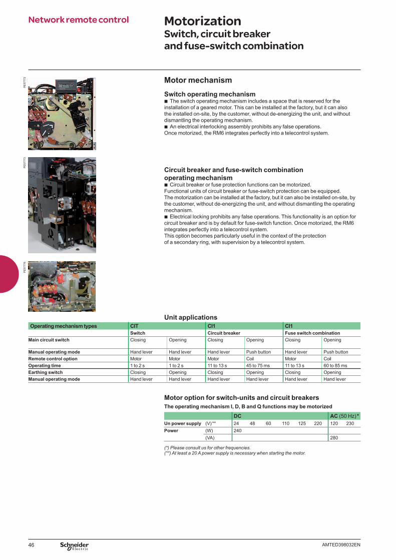
Motor mechanismSwitch operating mechanism
b The switch operating mechanism includes a space that is reserved for the installation of a geared motor. This can be installed at the factory, but it can also the installed on-site, by the customer, without de-energizing the unit, and without dismantling the operating mechanism.
b An electrical interlocking assembly prohibits any false operations.Once motorized, the RM6 integrates perfectly into a telecontrol system.
Circuit breaker and fuse-switch combination operating mechanism
b Circuit breaker or fuse protection functions can be motorized. Functional units of circuit breaker or fuse-switch protection can be equipped. The motorization can be installed at the factory, but it can also be installed on-site, by the customer, without de-energizing the unit, and without dismantling the operating mechanism.
b Electrical locking prohibits any false operations. This functionality is an option for circuit breaker and is by default for fuse-switch function. Once motorized, the RM6 integrates perfectly into a telecontrol system.This option becomes particularly useful in the context of the protection of a secondary ring, with supervision by a telecontrol system.
Unit applicationsOperating mechanism types CIT CI1 CI1
Switch Circuit breaker Fuse switch combinationMain circuit switch Closing Opening Closing Opening Closing Opening
Manual operating mode Hand lever Hand lever Hand lever Push button Hand lever Push buttonRemote control option Motor Motor Motor Coil Motor CoilOperating time 1 to 2 s 1 to 2 s 11 to 13 s 45 to 75 ms 11 to 13 s 60 to 85 msEarthing switch Closing Opening Closing Opening Closing OpeningManual operating mode Hand lever Hand lever Hand lever Hand lever Hand lever Hand lever
Motor option for switch-units and circuit breakersThe operating mechanism I, D, B and Q functions may be motorized
DC AC (50 Hz) *Un power supply (V) ** 24 48 60 110 125 220 120 230Power (W) 240
(VA) 280
(*) Please consult us for other frequencies.(**) At least a 20 A power supply is necessary when starting the motor.
Network remote control Motorization Switch, circuit breaker and fuse-switch combination
PE
5777
2P
E57
773
PE
5777
6
47AMTED398032EN
Accessories Contents
Indication and tripping 48
DIN indicatorsFault current and load currentFault current and voltage detection combination
494949
Other accessories 51
Operating handle 52
Key locking 53
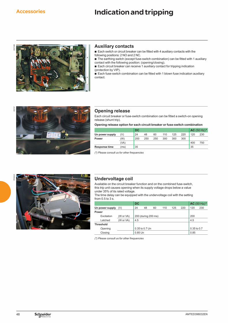
48 AMTED398032EN
0557
48B
0557
47P
E56
424
Auxiliary contacts b Each switch or circuit breaker can be fi tted with 4 auxiliary contacts with the
following positions: 2 NO and 2 NC. b The earthing switch (except fuse-switch combination) can be fi tted with 1 auxiliary
contact with the following position: (opening/closing). b Each circuit breaker can receive 1 auxiliary contact for tripping indication
(protection by VIP). b Each fuse-switch combination can be fi tted with 1 blown fuse indication auxiliary
contact.
Opening releaseEach circuit breaker or fuse-switch combination can be fi tted a switch-on opening release (shunt trip).Opening release option for each circuit breaker or fuse-switch combination
DC AC (50 Hz) *Un power supply (V) 24 48 60 110 125 220 120 230Power (W) 200 250 250 300 300 300
(VA) 400 750Response time (ms) 35 35
(*) Please consult us for other frequencies
Undervoltage coilAvailable on the circuit breaker function and on the combined fuse-switch, this trip unit causes opening when its supply voltage drops below a value under 35% of its rated voltage.The time delay can be equipped with the undervoltage coil with the setting from 0.5 to 3 s.
DC AC (50 Hz) *Un power supply (V) 24 48 60 110 125 220 120 230Power Excitation (W or VA) 200 (during 200 ms) 200 Latched (W or VA) 4.5 4.5Threshold Opening 0.35 to 0.7 Un 0.35 to 0.7 Closing 0.85 Un 0.85
(*) Please consult us for other frequencies
Accessories Indication and tripping
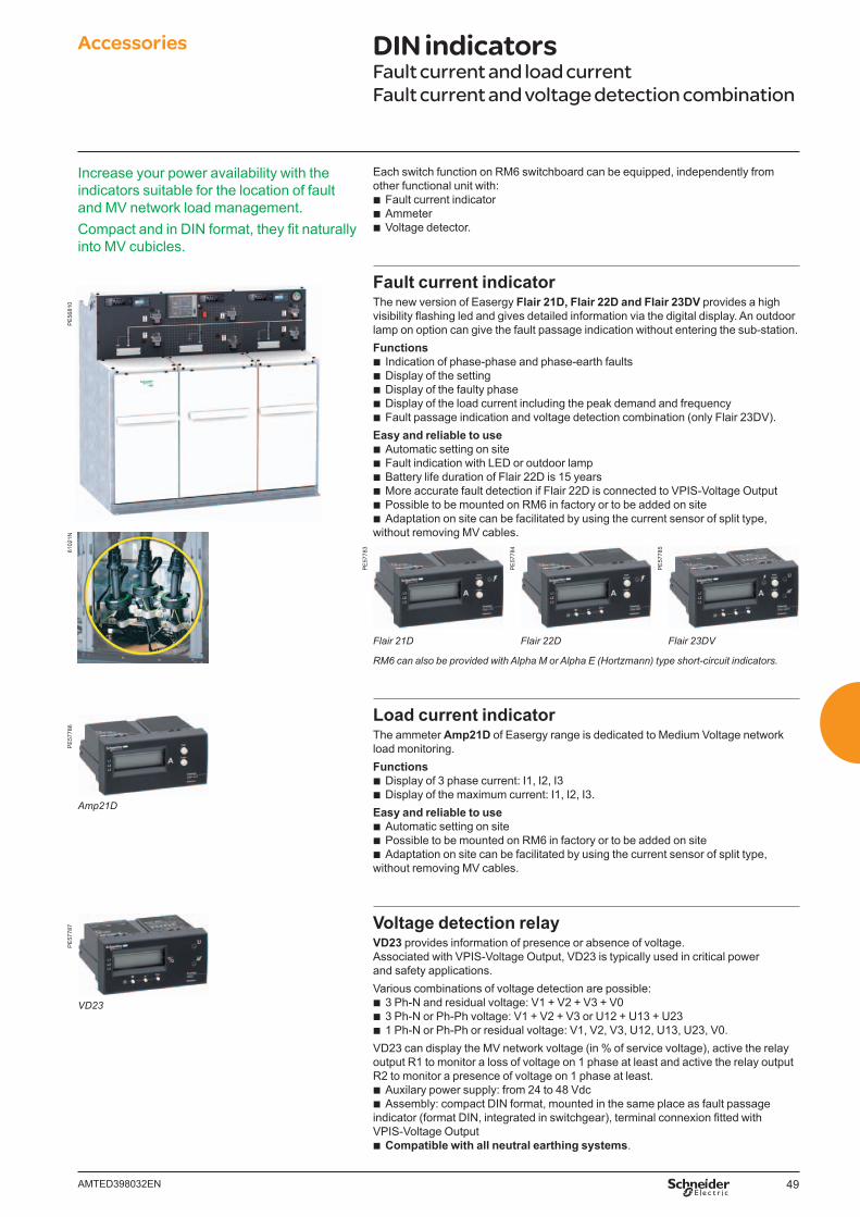
49AMTED398032EN
Each switch function on RM6 switchboard can be equipped, independently from other functional unit with:
b Fault current indicator b Ammeter b Voltage detector.
Fault current indicatorThe new version of Easergy Flair 21D, Flair 22D and Flair 23DV provides a high visibility fl ashing led and gives detailed information via the digital display. An outdoor lamp on option can give the fault passage indication without entering the sub-station.Functions
b Indication of phase-phase and phase-earth faults b Display of the setting b Display of the faulty phase b Display of the load current including the peak demand and frequency b Fault passage indication and voltage detection combination (only Flair 23DV).
Easy and reliable to use b Automatic setting on site b Fault indication with LED or outdoor lamp b Battery life duration of Flair 22D is 15 years b More accurate fault detection if Flair 22D is connected to VPIS-Voltage Output b Possible to be mounted on RM6 in factory or to be added on site b Adaptation on site can be facilitated by using the current sensor of split type,
without removing MV cables.
PE
5778
3
PE
5778
4
PE
5778
5
Flair 21D Flair 22D Flair 23DV
RM6 can also be provided with Alpha M or Alpha E (Hortzmann) type short-circuit indicators.
Load current indicatorThe ammeter Amp21D of Easergy range is dedicated to Medium Voltage network load monitoring.Functions
b Display of 3 phase current: I1, I2, I3 b Display of the maximum current: I1, I2, I3.
Easy and reliable to use b Automatic setting on site b Possible to be mounted on RM6 in factory or to be added on site b Adaptation on site can be facilitated by using the current sensor of split type,
without removing MV cables.
Voltage detection relayVD23 provides information of presence or absence of voltage. Associated with VPIS-Voltage Output, VD23 is typically used in critical power and safety applications.Various combinations of voltage detection are possible:
b 3 Ph-N and residual voltage: V1 + V2 + V3 + V0 b 3 Ph-N or Ph-Ph voltage: V1 + V2 + V3 or U12 + U13 + U23 b 1 Ph-N or Ph-Ph or residual voltage: V1, V2, V3, U12, U13, U23, V0.
VD23 can display the MV network voltage (in % of service voltage), active the relay output R1 to monitor a loss of voltage on 1 phase at least and active the relay output R2 to monitor a presence of voltage on 1 phase at least.
b Auxilary power supply: from 24 to 48 Vdc b Assembly: compact DIN format, mounted in the same place as fault passage
indicator (format DIN, integrated in switchgear), terminal connexion fi tted with VPIS-Voltage Output
b Compatible with all neutral earthing systems.
Accessories DIN indicatorsFault current and load currentFault current and voltage detection combination
6102
1N
Increase your power availability with the indicators suitable for the location of fault and MV network load management.Compact and in DIN format, they fi t naturally into MV cubicles.
PE
5681
0P
E57
787
PE
5778
6
VD23
Amp21D
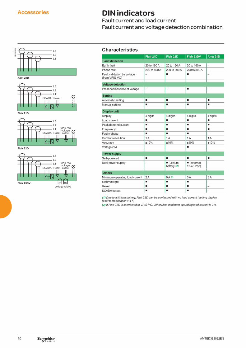
50 AMTED398032EN
DE
5798
1EN
Flair 21D
Flair 22D
SCADA
L3L2L1
L3L2L1
Reset
Flair 23DV
SCADA Reset
VPIS-VOvoltageoutput
VPIS-VOvoltageoutput
SCADA Reset
L3L2L1
AMP 21D
L3L2L1
Voltage relaysR1 R2
CharacteristicsFlair 21D Flair 22D Flair 23DV Amp 21D
Fault detectionEarth fault 20 to 160 A 20 to 160 A 20 to 160 A –Phase fault 200 to 800 A 200 to 800 A 200 to 800 A –Fault validation by voltage(from VPIS-VO)
– b b –
Voltage detectionPresence/absence of voltage – – b –
SettingAutomatic setting b b b b
Manual setting b b b b
Display unitDisplay 4 digits 4 digits 4 digits 4 digitsLoad current b b b b
Peak demand current b b b b
Frequency b b b b
Faulty phase b b b –Current resolution 1 A 1 A 1 A 1 AAccuracy ±10% ±10% ±10% ±10%Voltage (%) b
Power supplySelf-powered b b b b
Dual power supply – b (Lithium battery) (1)
b (external 12-48 Vdc)
–
OthersMinimum operating load current 2 A 0 A (2) 0 A 3 AExternal light b b b –Reset b b b –SCADA output b b b –
(1) Due to a lithium battery, Flair 22D can be confi gured with no load current (setting display, reset temporisation > 4 h)(2) If Flair 22D is connected to VPIS-VO. Otherwise, minimum operating load current is 2 A.
Accessories DIN indicatorsFault current and load currentFault current and voltage detection combination
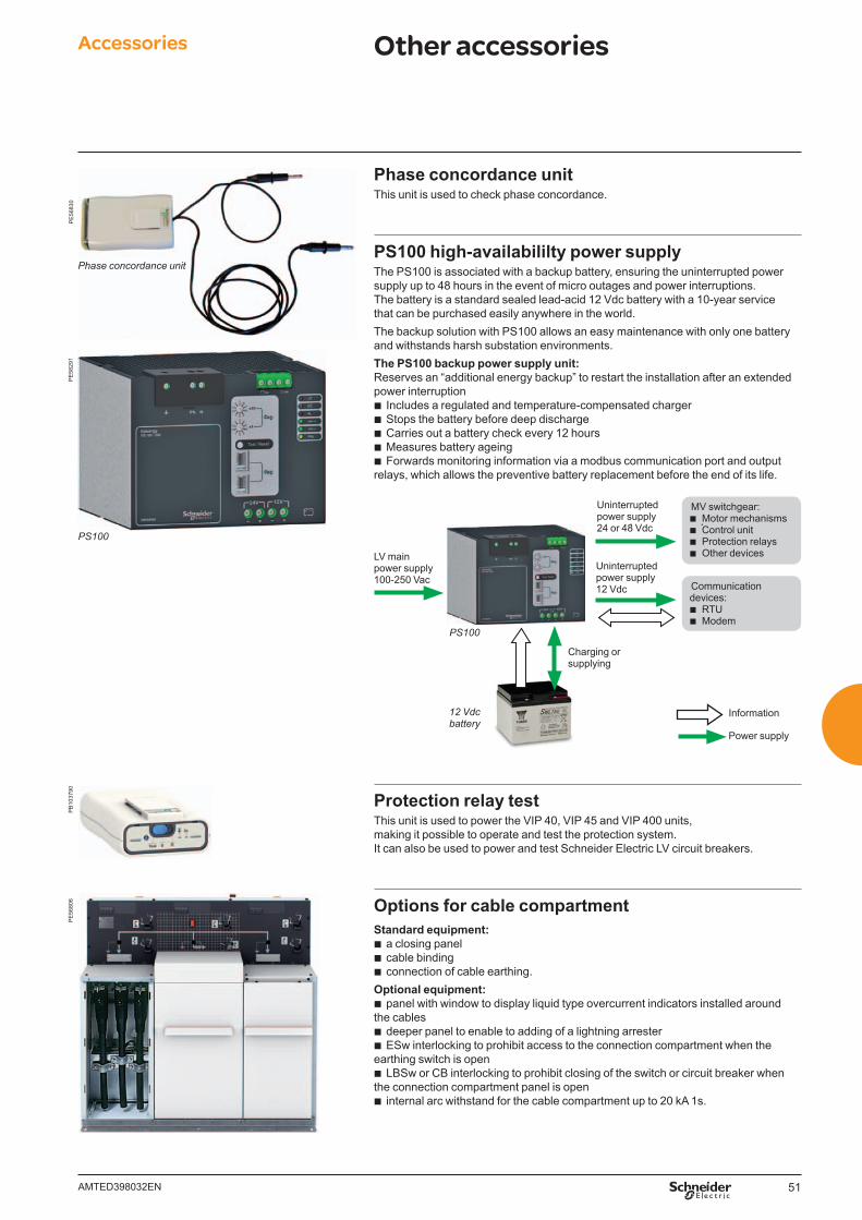
51AMTED398032EN
Phase concordance unitThis unit is used to check phase concordance.
PS100 high-availabililty power supplyThe PS100 is associated with a backup battery, ensuring the uninterrupted power supply up to 48 hours in the event of micro outages and power interruptions. The battery is a standard sealed lead-acid 12 Vdc battery with a 10-year service that can be purchased easily anywhere in the world.The backup solution with PS100 allows an easy maintenance with only one battery and withstands harsh substation environments.The PS100 backup power supply unit:Reserves an “additional energy backup” to restart the installation after an extended power interruption
b Includes a regulated and temperature-compensated charger b Stops the battery before deep discharge b Carries out a battery check every 12 hours b Measures battery ageing b Forwards monitoring information via a modbus communication port and output
relays, which allows the preventive battery replacement before the end of its life.
MV switchgear: b Motor mechanisms b Control unit b Protection relays b Other devices
Uninterrupted power supply24 or 48 Vdc
Uninterrupted power supply12 Vdc
Charging or supplying
LV main power supply100-250 Vac
PS100
12 Vdc battery
Power supply
Information
Communication devices:
b RTU b Modem
Protection relay testThis unit is used to power the VIP 40, VIP 45 and VIP 400 units, making it possible to operate and test the protection system. It can also be used to power and test Schneider Electric LV circuit breakers.
Options for cable compartmentStandard equipment:
b a closing panel b cable binding b connection of cable earthing.
Optional equipment: b panel with window to display liquid type overcurrent indicators installed around
the cables b deeper panel to enable to adding of a lightning arrester b ESw interlocking to prohibit access to the connection compartment when the
earthing switch is open b LBSw or CB interlocking to prohibit closing of the switch or circuit breaker when
the connection compartment panel is open b internal arc withstand for the cable compartment up to 20 kA 1s.
Accessories Other accessoriesP
E56
830
PE
5680
6
Phase concordance unit
PE
5829
1
PS100
PB
1037
90
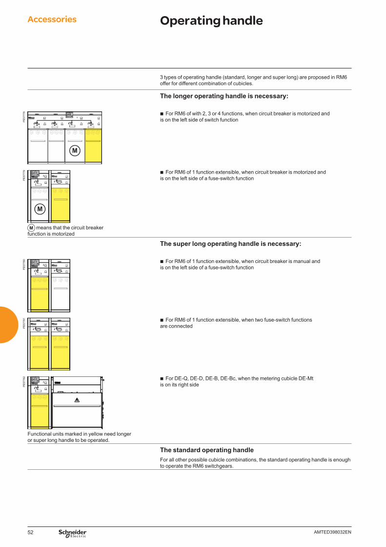
52 AMTED398032EN
Accessories Operating handle
3 types of operating handle (standard, longer and super long) are proposed in RM6 offer for different combination of cubicles.
The longer operating handle is necessary:
PE
5777
8 b For RM6 of with 2, 3 or 4 functions, when circuit breaker is motorized and is on the left side of switch function
PE
5777
9
M means that the circuit breaker function is motorized
b For RM6 of 1 function extensible, when circuit breaker is motorized and is on the left side of a fuse-switch function
The super long operating handle is necessary:
PE
5778
0 b For RM6 of 1 function extensible, when circuit breaker is manual and is on the left side of a fuse-switch function
PE
5778
1 b For RM6 of 1 function extensible, when two fuse-switch functions are connected
PE
5778
2
Functional units marked in yellow need longer or super long handle to be operated.
b For DE-Q, DE-D, DE-B, DE-Bc, when the metering cubicle DE-Mt is on its right side
The standard operating handleFor all other possible cubicle combinations, the standard operating handle is enough to operate the RM6 switchgears.
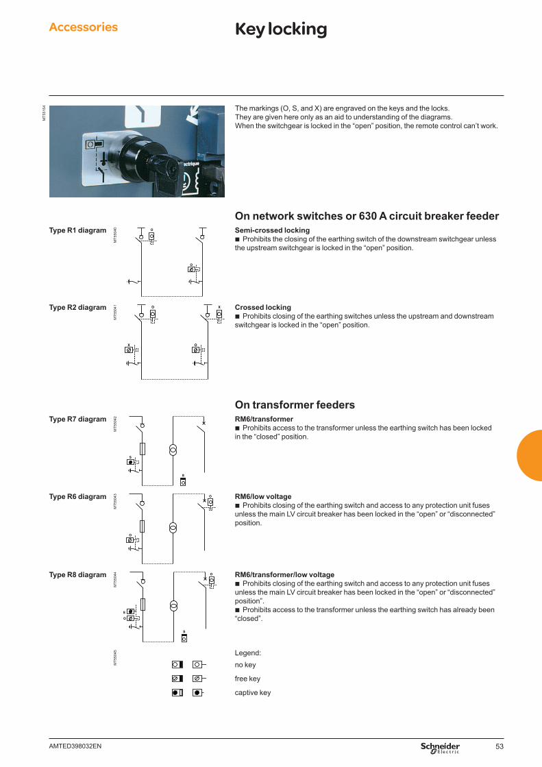
53AMTED398032EN
The markings (O, S, and X) are engraved on the keys and the locks.They are given here only as an aid to understanding of the diagrams.When the switchgear is locked in the “open” position, the remote control can’t work.
MT5
5154
On network switches or 630 A circuit breaker feederType R1 diagram
MT5
5040
O
O Semi-crossed locking b Prohibits the closing of the earthing switch of the downstream switchgear unless
the upstream switchgear is locked in the “open” position.
Type R2 diagram
MT5
5041
OX
O X Crossed locking b Prohibits closing of the earthing switches unless the upstream and downstream
switchgear is locked in the “open” position.
On transformer feedersType R7 diagram
MT5
5042
S
S
RM6/transformer b Prohibits access to the transformer unless the earthing switch has been locked
in the “closed” position.
Type R6 diagram
MT5
5043
O
O RM6/low voltage b Prohibits closing of the earthing switch and access to any protection unit fuses
unless the main LV circuit breaker has been locked in the “open” or “disconnected” position.
Type R8 diagram
MT5
5044
S
S
O
O RM6/transformer/low voltage b Prohibits closing of the earthing switch and access to any protection unit fuses
unless the main LV circuit breaker has been locked in the “open” or “disconnected” position”.
b Prohibits access to the transformer unless the earthing switch has already been “closed”.
MT5
5045
Legend:no key
free key
captive key
Accessories Key locking

54 AMTED398032EN.indd
55AMTED398032EN
MV connection Contents
Selecting bushings and connectors 56
Compatible cable connections 57
Other types of compatible connections 59
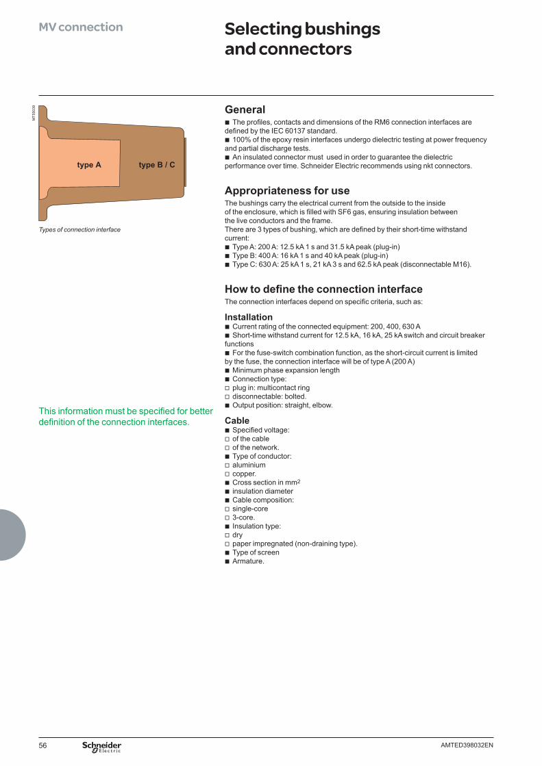
56 AMTED398032EN
General b The profi les, contacts and dimensions of the RM6 connection interfaces are
defi ned by the IEC 60137 standard. b 100% of the epoxy resin interfaces undergo dielectric testing at power frequency
and partial discharge tests. b An insulated connector must used in order to guarantee the dielectric
performance over time. Schneider Electric recommends using nkt connectors.
Appropriateness for useThe bushings carry the electrical current from the outside to the inside of the enclosure, which is fi lled with SF6 gas, ensuring insulation between the live conductors and the frame.There are 3 types of bushing, which are defi ned by their short-time withstand current:
b Type A: 200 A: 12.5 kA 1 s and 31.5 kA peak (plug-in) b Type B: 400 A: 16 kA 1 s and 40 kA peak (plug-in) b Type C: 630 A: 25 kA 1 s, 21 kA 3 s and 62.5 kA peak (disconnectable M16).
How to defi ne the connection interfaceThe connection interfaces depend on specifi c criteria, such as:
Installation b Current rating of the connected equipment: 200, 400, 630 A b Short-time withstand current for 12.5 kA, 16 kA, 25 kA switch and circuit breaker
functions b For the fuse-switch combination function, as the short-circuit current is limited
by the fuse, the connection interface will be of type A (200 A) b Minimum phase expansion length b Connection type: v plug in: multicontact ring v disconnectable: bolted. b Output position: straight, elbow.
Cable b Specifi ed voltage: v of the cable v of the network. b Type of conductor: v aluminium v copper. b Cross section in mm2
b insulation diameter b Cable composition: v single-core v 3-core. b Insulation type: v dry v paper impregnated (non-draining type). b Type of screen b Armature.
MT5
5039
Types of connection interface
This information must be specifi ed for better defi nition of the connection interfaces.
MV connection Selecting bushings and connectors
type B / Ctype A
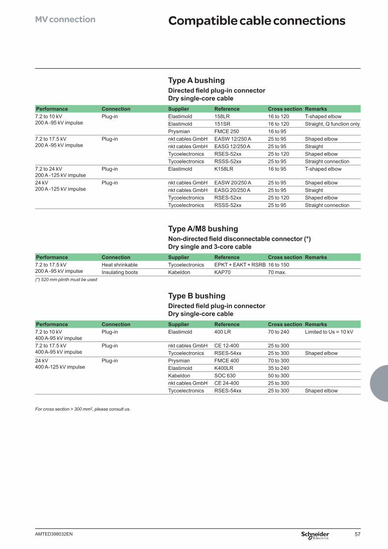
57AMTED398032EN
Type A bushingDirected fi eld plug-in connector Dry single-core cable
Performance Connection Supplier Reference Cross section Remarks7.2 to 10 kV200 A -95 kV impulse
Plug-in Elastimold 158LR 16 to 120 T-shaped elbowElastimold 151SR 16 to 120 Straight, Q function onlyPrysmian FMCE 250 16 to 95
7.2 to 17.5 kV200 A -95 kV impulse
Plug-in nkt cables GmbH EASW 12/250 A 25 to 95 Shaped elbownkt cables GmbH EASG 12/250 A 25 to 95 StraightTycoelectronics RSES-52xx 25 to 120 Shaped elbowTycoelectronics RSSS-52xx 25 to 95 Straight connection
7.2 to 24 kV200 A -125 kV impulse
Plug-in Elastimold K158LR 16 to 95 T-shaped elbow
24 kV200 A -125 kV impulse
Plug-in nkt cables GmbH EASW 20/250 A 25 to 95 Shaped elbownkt cables GmbH EASG 20/250 A 25 to 95 StraightTycoelectronics RSES-52xx 25 to 120 Shaped elbowTycoelectronics RSSS-52xx 25 to 95 Straight connection
Type A/M8 bushingNon-directed fi eld disconnectable connector (*)Dry single and 3-core cable
Performance Connection Supplier Reference Cross section Remarks7.2 to 17.5 kV200 A -95 kV impulse
Heat shrinkable Tycoelectronics EPKT + EAKT + RSRB 16 to 150 Insulating boots Kabeldon KAP70 70 max.
(*) 520 mm plinth must be used
Type B bushingDirected fi eld plug-in connector Dry single-core cable
Performance Connection Supplier Reference Cross section Remarks7.2 to 10 kV400 A-95 kV impulse
Plug-in Elastimold 400 LR 70 to 240 Limited to Us = 10 kV
7.2 to 17.5 kV400 A-95 kV impulse
Plug-in nkt cables GmbH CE 12-400 25 to 300Tycoelectronics RSES-54xx 25 to 300 Shaped elbow
24 kV400 A-125 kV impulse
Plug-in Prysmian FMCE 400 70 to 300Elastimold K400LR 35 to 240Kabeldon SOC 630 50 to 300nkt cables GmbH CE 24-400 25 to 300Tycoelectronics RSES-54xx 25 to 300 Shaped elbow
For cross section > 300 mm2, please consult us.
MV connection Compatible cable connections
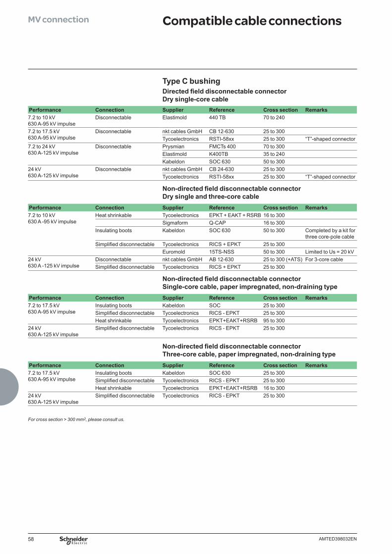
58 AMTED398032EN
MV connection Compatible cable connections
Type C bushingDirected fi eld disconnectable connector Dry single-core cable
Performance Connection Supplier Reference Cross section Remarks7.2 to 10 kV630 A-95 kV impulse
Disconnectable Elastimold 440 TB 70 to 240
7.2 to 17.5 kV630 A-95 kV impulse
Disconnectable nkt cables GmbH CB 12-630 25 to 300Tycoelectronics RSTI-58xx 25 to 300 “T”-shaped connector
7.2 to 24 kV630 A-125 kV impulse
Disconnectable Prysmian FMCTs 400 70 to 300Elastimold K400TB 35 to 240Kabeldon SOC 630 50 to 300
24 kV630 A-125 kV impulse
Disconnectable nkt cables GmbH CB 24-630 25 to 300Tycoelectronics RSTI-58xx 25 to 300 “T”-shaped connector
Non-directed fi eld disconnectable connector Dry single and three-core cable
Performance Connection Supplier Reference Cross section Remarks7.2 to 10 kV630 A -95 kV impulse
Heat shrinkable Tycoelectronics EPKT + EAKT + RSRB 16 to 300 Sigmaform Q-CAP 16 to 300
Insulating boots Kabeldon SOC 630 50 to 300 Completed by a kit for three core-pole cable
Simplifi ed disconnectable Tycoelectronics RICS + EPKT 25 to 300 Euromold 15TS-NSS 50 to 300 Limited to Us = 20 kV
24 kV630 A -125 kV impulse
Disconnectable nkt cables GmbH AB 12-630 25 to 300 (+ATS) For 3-core cableSimplifi ed disconnectable Tycoelectronics RICS + EPKT 25 to 300
Non-directed fi eld disconnectable connector Single-core cable, paper impregnated, non-draining type
Performance Connection Supplier Reference Cross section Remarks7.2 to 17.5 kV630 A-95 kV impulse
Insulating boots Kabeldon SOC 25 to 300Simplifi ed disconnectable Tycoelectronics RICS - EPKT 25 to 300Heat shrinkable Tycoelectronics EPKT+EAKT+RSRB 95 to 300
24 kV630 A-125 kV impulse
Simplifi ed disconnectable Tycoelectronics RICS - EPKT 25 to 300
Non-directed fi eld disconnectable connector Three-core cable, paper impregnated, non-draining type
Performance Connection Supplier Reference Cross section Remarks7.2 to 17.5 kV630 A-95 kV impulse
Insulating boots Kabeldon SOC 630 25 to 300Simplifi ed disconnectable Tycoelectronics RICS - EPKT 25 to 300Heat shrinkable Tycoelectronics EPKT+EAKT+RSRB 16 to 300
24 kV630 A-125 kV impulse
Simplifi ed disconnectable Tycoelectronics RICS - EPKT 25 to 300
For cross section > 300 mm2, please consult us.
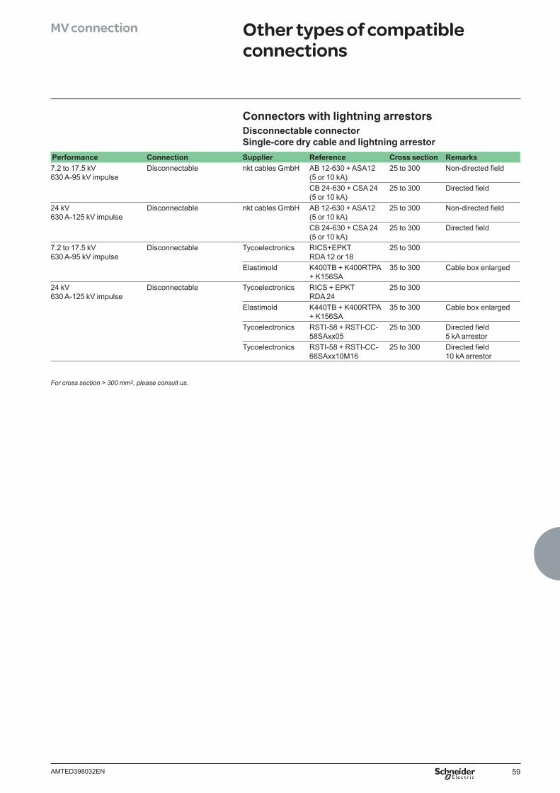
59AMTED398032EN
Connectors with lightning arrestorsDisconnectable connector Single-core dry cable and lightning arrestor
Performance Connection Supplier Reference Cross section Remarks7.2 to 17.5 kV630 A-95 kV impulse
Disconnectable nkt cables GmbH AB 12-630 + ASA12(5 or 10 kA)
25 to 300 Non-directed fi eld
CB 24-630 + CSA 24(5 or 10 kA)
25 to 300 Directed fi eld
24 kV630 A-125 kV impulse
Disconnectable nkt cables GmbH AB 12-630 + ASA12(5 or 10 kA)
25 to 300 Non-directed fi eld
CB 24-630 + CSA 24(5 or 10 kA)
25 to 300 Directed fi eld
7.2 to 17.5 kV630 A-95 kV impulse
Disconnectable Tycoelectronics RICS+EPKTRDA 12 or 18
25 to 300
Elastimold K400TB + K400RTPA+ K156SA
35 to 300 Cable box enlarged
24 kV630 A-125 kV impulse
Disconnectable Tycoelectronics RICS + EPKTRDA 24
25 to 300
Elastimold K440TB + K400RTPA+ K156SA
35 to 300 Cable box enlarged
Tycoelectronics RSTI-58 + RSTI-CC-58SAxx05
25 to 300 Directed fi eld 5 kA arrestor
Tycoelectronics RSTI-58 + RSTI-CC-66SAxx10M16
25 to 300 Directed fi eld 10 kA arrestor
For cross section > 300 mm2, please consult us.
MV connection Other types of compatible connections

60 AMTED398032EN.indd
61AMTED398032EN
Installation Contents
Dimensions and installation conditions 62
Civil works 66
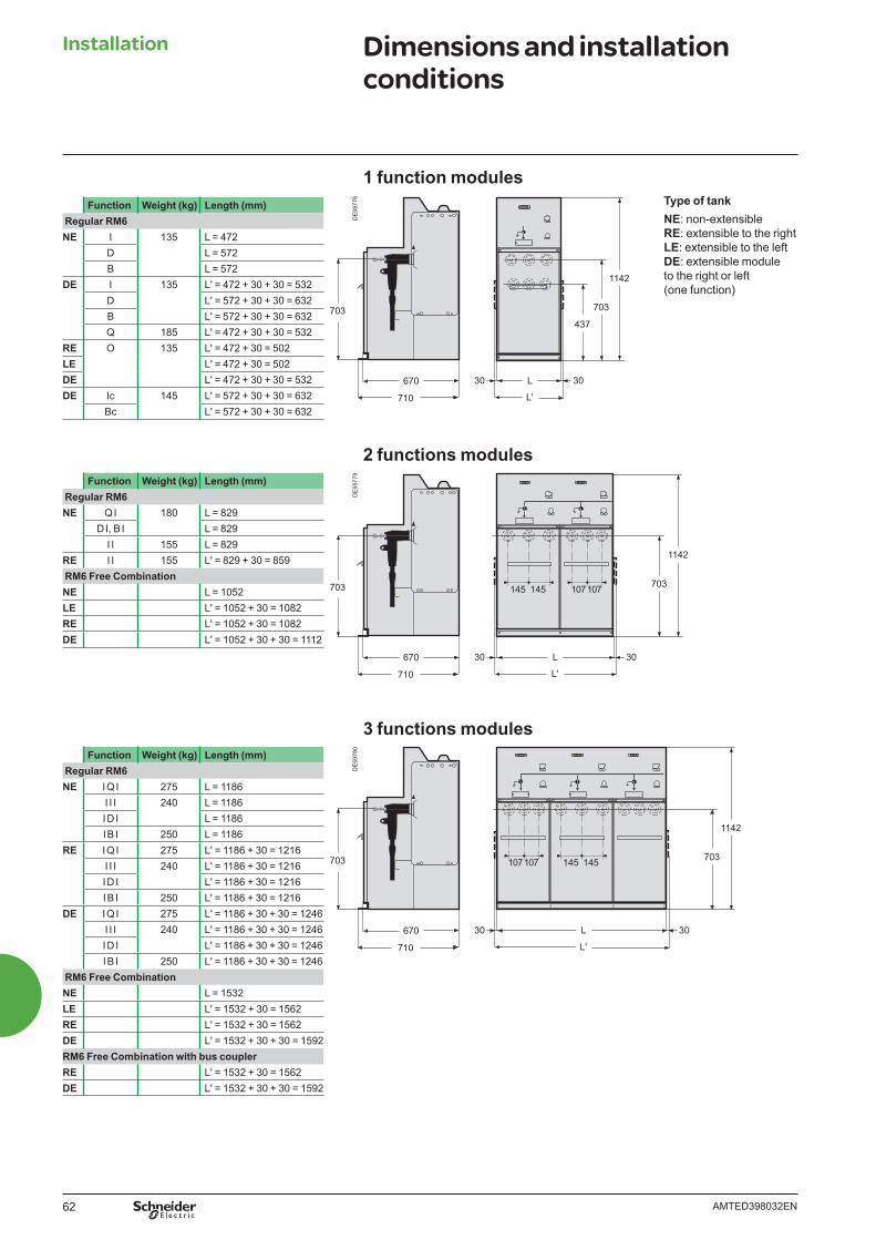
62 AMTED398032EN
Installation Dimensions and installation conditions
1142
437
703
L 3030
L'710
670
703
703
L 3030
L'
1142
710
670
703 145 145 107107
145 145
L 3030
L'710
670
703 703
1142
107107
DE
5977
8D
E59
779
DE
5978
0
1 function modules
2 functions modules
3 functions modules
Function Weight (kg) Length (mm) Regular RM6NE I 135 L = 472
D L = 572B L = 572
DE I 135 L' = 472 + 30 + 30 = 532D L' = 572 + 30 + 30 = 632B L' = 572 + 30 + 30 = 632Q 185 L' = 472 + 30 + 30 = 532
RE O 135 L' = 472 + 30 = 502LE L' = 472 + 30 = 502DE L' = 472 + 30 + 30 = 532DE Ic 145 L' = 572 + 30 + 30 = 632
Bc L' = 572 + 30 + 30 = 632
Function Weight (kg) Length (mm) Regular RM6NE I Q I 275 L = 1186
I I I 240 L = 1186I D I L = 1186I B I 250 L = 1186
RE I Q I 275 L' = 1186 + 30 = 1216I I I 240 L' = 1186 + 30 = 1216I D I L' = 1186 + 30 = 1216I B I 250 L' = 1186 + 30 = 1216
DE I Q I 275 L' = 1186 + 30 + 30 = 1246I I I 240 L' = 1186 + 30 + 30 = 1246I D I L' = 1186 + 30 + 30 = 1246I B I 250 L' = 1186 + 30 + 30 = 1246
RM6 Free CombinationNE L = 1532LE L' = 1532 + 30 = 1562RE L' = 1532 + 30 = 1562DE L' = 1532 + 30 + 30 = 1592RM6 Free Combination with bus couplerRE L' = 1532 + 30 = 1562DE L' = 1532 + 30 + 30 = 1592
Function Weight (kg) Length (mm) Regular RM6NE Q I 180 L = 829
D I, B I L = 829I I 155 L = 829
RE I I 155 L' = 829 + 30 = 859 RM6 Free CombinationNE L = 1052LE L' = 1052 + 30 = 1082RE L' = 1052 + 30 = 1082DE L' = 1052 + 30 + 30 = 1112
Type of tankNE: non-extensibleRE: extensible to the rightLE: extensible to the leftDE: extensible module to the right or left (one function)
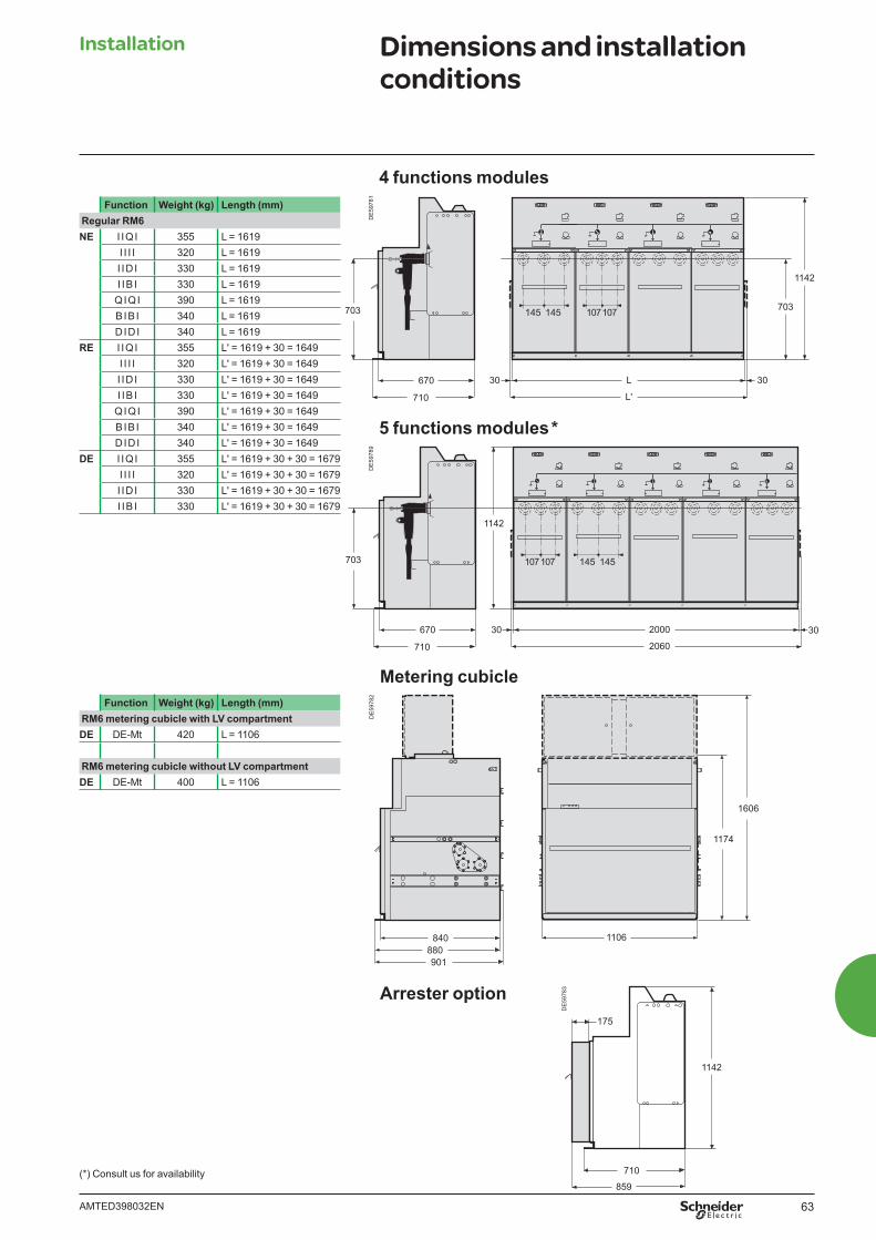
63AMTED398032EN
Installation Dimensions and installation conditions
Function Weight (kg) Length (mm) Regular RM6NE I I Q I 355 L = 1619
I I I I 320 L = 1619I I D I 330 L = 1619I I B I 330 L = 1619
Q I Q I 390 L = 1619B I B I 340 L = 1619D I D I 340 L = 1619
RE I I Q I 355 L' = 1619 + 30 = 1649I I I I 320 L' = 1619 + 30 = 1649I I D I 330 L' = 1619 + 30 = 1649I I B I 330 L' = 1619 + 30 = 1649
Q I Q I 390 L' = 1619 + 30 = 1649B I B I 340 L' = 1619 + 30 = 1649D I D I 340 L' = 1619 + 30 = 1649
DE I I Q I 355 L' = 1619 + 30 + 30 = 1679I I I I 320 L' = 1619 + 30 + 30 = 1679I I D I 330 L' = 1619 + 30 + 30 = 1679I I B I 330 L' = 1619 + 30 + 30 = 1679
Function Weight (kg) Length (mm) RM6 metering cubicle with LV compartmentDE DE-Mt 420 L = 1106
RM6 metering cubicle without LV compartmentDE DE-Mt 400 L = 1106
2000 3030
2060710
670
1142
107107 145 145703
L 3030
L'710
670
703 703
1142
145 145 107107
DE
5978
1D
E59
789
4 functions modules
5 functions modules *
Metering cubicle
Arrester option
DE
5978
2
DE
5978
3
1106880901
840
1174
1606
710
175
859
1142
(*) Consult us for availability
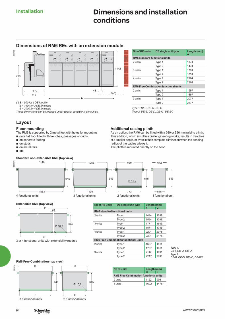
64 AMTED398032EN
645
1563
1689
645
1130
1256
645
773
899
Ø 10,2645
516
642
645
43F
G
Ø 10,2
DE
5797
3D
E59
784
Dimensions of RM6 REs with an extension module
Floor mountingThe RM6 is supported by 2 metal feet with holes for mounting:
b on a fl at fl oor fi tted with trenches, passages or ducts b on concrete footing b on studs b on metal rails b etc.
Extensible RM6 (top view)
RM6 Free Combination (top view)
Standard non-extensible RM6 (top view)
4 functional units 3 functional units 2 functional units 1 functional unit
3 or 4 functional units with extensibility module
Installation Dimensions and installation conditions
Additional raising plinthAs an option, the RM6 can be fi tted with a 260 or 520 mm raising plinth.This addition, which simplifi es civil engineering works, results in trenches of a smaller depth, or even in their complete elimination when the bending radius of the cables allows it.The plinth is mounted directly on the fl oor.
Layout
1142
43B (*)
A710
670
703
DE
5799
3
645
E
D
645
E
D
Ø 10,2
3 functional units 2 functional units
(*) B = 900 for 1 DE functionB = 1600 for 3 DE functionsB = 2000 for 4 DE functions
These dimensions can be reduced under special conditions, consult us.
Nb of RE units DE single unit type Length (mm)F G
RM6 standard functional units2 units Type 1 1414 1288
Type 2 1514 13883 units Type 1 1771 1645
Type 2 1871 17454 units Type 1 2204 2078
Type 2 2304 2178RM6 Free Combination functional units2 units Type 1 1637 1511
Type 2 1737 16113 units Type 1 2117 1991
Type 2 2217 2091
Nb of units Length (mm)D E
RM6 Free Combination functional units2 units 1122 9963 units 1602 1476
Type 1: DE-I, DE-Q, DE-OType 2: DE-B, DE-D, DE-IC, DE-BC
Nb of RE units DE single unit type Length (mm)A
RM6 standard functional units2 units Type 1 1374
Type 2 14743 units Type 1 1731
Type 2 18314 units Type 1 2164
Type 2 2264RM6 Free Combination functional units2 units Type 1 1597
Type 2 16973 units Type 1 2077
Type 2 2177
Type 1: DE-I, DE-Q, DE-OType 2: DE-B, DE-D, DE-IC, DE-BC
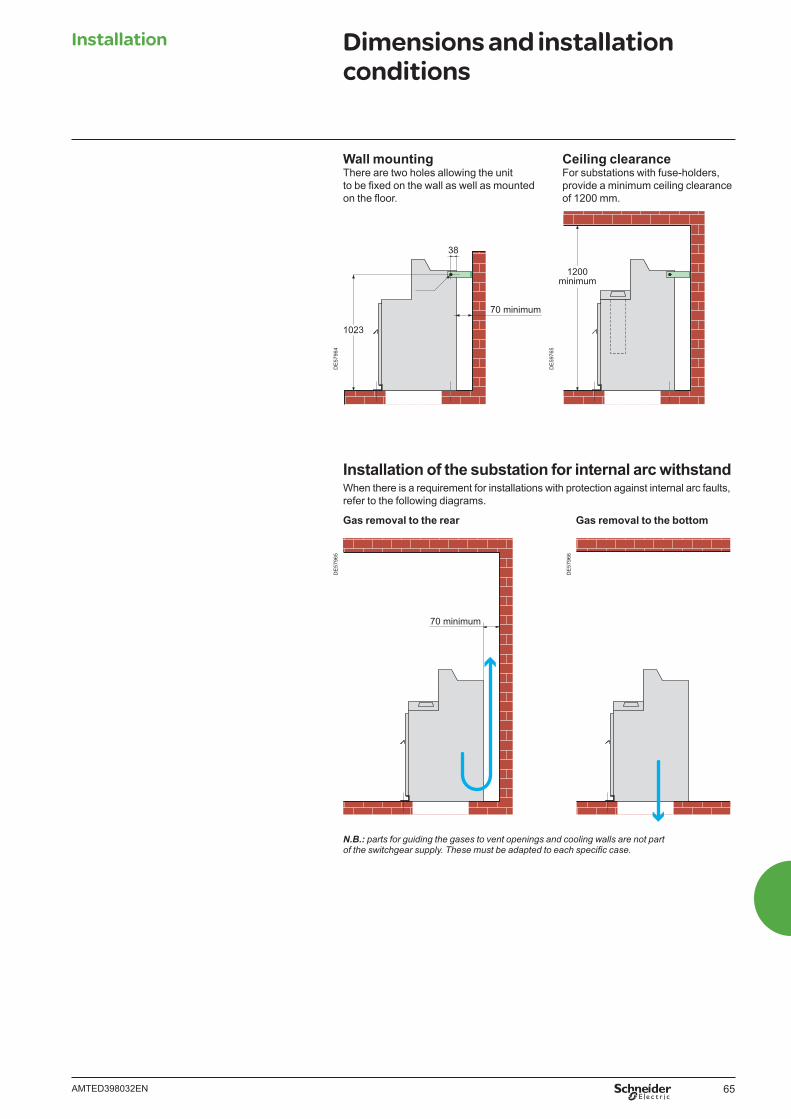
65AMTED398032EN
DE
5976
5
1200minimum
DE
5796
4
38
1023
Ø12
70 minimum
Wall mountingThere are two holes allowing the unit to be fi xed on the wall as well as mounted on the fl oor.
Ceiling clearanceFor substations with fuse-holders, provide a minimum ceiling clearance of 1200 mm.
Installation of the substation for internal arc withstandWhen there is a requirement for installations with protection against internal arc faults, refer to the following diagrams.
Gas removal to the bottom
N.B.: parts for guiding the gases to vent openings and cooling walls are not part of the switchgear supply. These must be adapted to each specifi c case.
Installation Dimensions and installation conditions
DE
5796
5
70 minimum
Gas removal to the rear
DE
5796
6
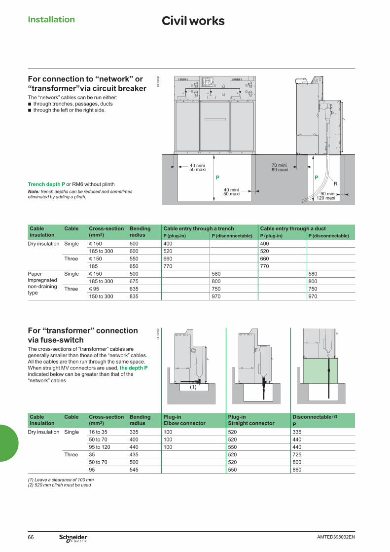
66 AMTED398032EN
For connection to “network” or “transformer”via circuit breakerThe “network” cables can be run either:
b through trenches, passages, ducts b through the left or the right side.
Trench depth P or RM6 without plinthNote: trench depths can be reduced and sometimes eliminated by adding a plinth.
DE
5806
0D
E57
962
(1)
Cableinsulation
Cable Cross-section(mm2)
Bendingradius
Cable entry through a trench Cable entry through a ductP (plug-in) P (disconnectable) P (plug-in) P (disconnectable)
Dry insulation Single y 150 500 400 400185 to 300 600 520 520
Three y 150 550 660 660185 650 770 770
Paper impregnatednon-draining type
Single y 150 500 580 580185 to 300 675 800 800
Three y 95 635 750 750150 to 300 835 970 970
For “transformer” connection via fuse-switchThe cross-sections of “transformer” cables are generally smaller than those of the “network” cables.All the cables are then run through the same space.When straight MV connectors are used, the depth P indicated below can be greater than that of the“network” cables.
Cableinsulation
Cable Cross-section(mm2)
Bendingradius
Plug-inElbow connector
Plug-inStraight connector
Disconnectable (2)
PDry insulation Single 16 to 35 335 100 520 335
50 to 70 400 100 520 44095 to 120 440 100 550 440
Three 35 435 520 72550 to 70 500 520 80095 545 550 860
(1) Leave a clearance of 100 mm(2) 520 mm plinth must be used
Installation Civil works
P50 maxi40 mini
P
50 maxi40 mini
90 mini
R
80 maxi70 mini
120 maxi
67AMTED398032EN
Order form Contents
Available functions 68
Basic unit and options 69
Options and accessories 71
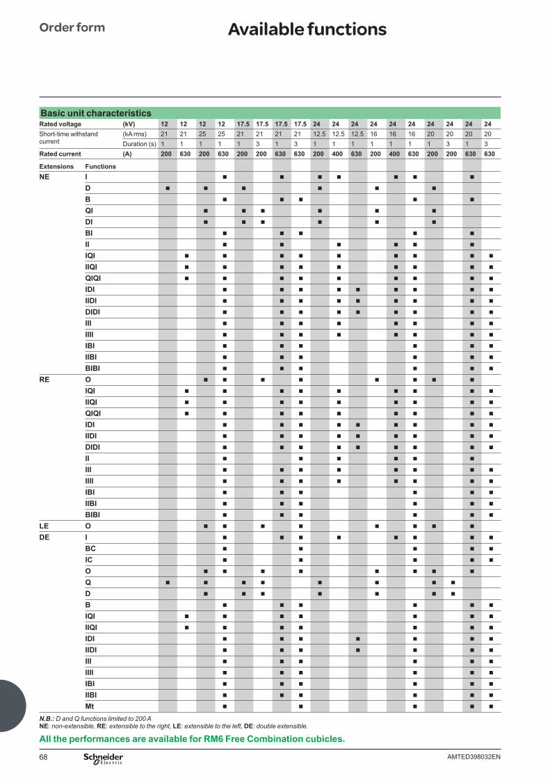
68 AMTED398032EN
Basic unit characteristicsRated voltage (kV) 12 12 12 12 17.5 17.5 17.5 17.5 24 24 24 24 24 24 24 24 24 24Short-time withstand current
(kA rms) 21 21 25 25 21 21 21 21 12.5 12.5 12.5 16 16 16 20 20 20 20Duration (s) 1 1 1 1 1 3 1 3 1 1 1 1 1 1 1 3 1 3
Rated current (A) 200 630 200 630 200 200 630 630 200 400 630 200 400 630 200 200 630 630
Extensions FunctionsNE I b b b b b b b
D b b b b b b
B b b b b b
QI b b b b b b
DI b b b b b b
BI b b b b b
II b b b b b b
IQI b b b b b b b b b
IIQI b b b b b b b b b
QIQI b b b b b b b b b
IDI b b b b b b b b b
IIDI b b b b b b b b b
DIDI b b b b b b b b b
III b b b b b b b b
IIII b b b b b b b b
IBI b b b b b b
IIBI b b b b b b
BIBI b b b b b b
RE O b b b b b b b b
IQI b b b b b b b b b
IIQI b b b b b b b b b
QIQI b b b b b b b b b
IDI b b b b b b b b b
IIDI b b b b b b b b b
DIDI b b b b b b b b b
II b b b b b b
III b b b b b b b b
IIII b b b b b b b b
IBI b b b b b b
IIBI b b b b b b
BIBI b b b b b b
LE O b b b b b b b b
DE I b b b b b b b b
BC b b b b b
IC b b b b b
O b b b b b b b b
Q b b b b b b b b
D b b b b b b b
B b b b b b b
IQI b b b b b b b
IIQI b b b b b b b
IDI b b b b b b b
IIDI b b b b b b b
III b b b b b b
IIII b b b b b b
IBI b b b b b b
IIBI b b b b b b
Mt b b b b b
N.B.: D and Q functions limited to 200 ANE: non-extensible, RE: extensible to the right, LE: extensible to the left, DE: double extensible.
All the performances are available for RM6 Free Combination cubicles.
Order form Available functions
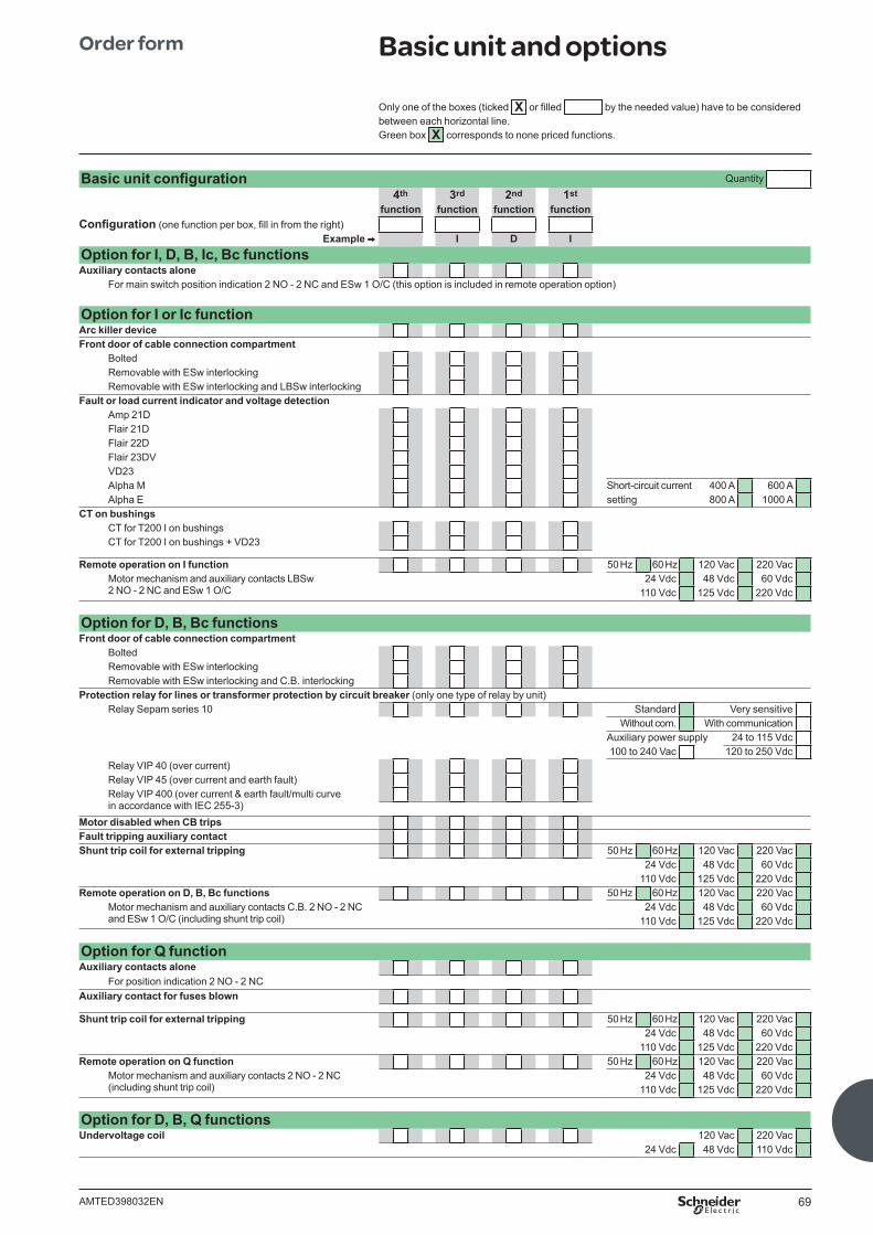
69AMTED398032EN
Basic unit confi guration Quantity4th 3rd 2nd 1st
function function function functionConfi guration (one function per box, fi ll in from the right)
Example V I D I Option for I, D, B, Ic, Bc functionsAuxiliary contacts alone
For main switch position indication 2 NO - 2 NC and ESw 1 O/C (this option is included in remote operation option)
Option for I or Ic functionArc killer device Front door of cable connection compartment
BoltedRemovable with ESw interlockingRemovable with ESw interlocking and LBSw interlocking
Fault or load current indicator and voltage detectionAmp 21DFlair 21DFlair 22DFlair 23DVVD23Alpha M Short-circuit current 400 A 600 AAlpha E setting 800 A 1000 A
CT on bushingsCT for T200 I on bushingsCT for T200 I on bushings + VD23
Remote operation on I function 50 Hz 60 Hz 120 Vac 220 VacMotor mechanism and auxiliary contacts LBSw 2 NO - 2 NC and ESw 1 O/C
24 Vdc 48 Vdc 60 Vdc110 Vdc 125 Vdc 220 Vdc
Option for D, B, Bc functions Front door of cable connection compartment
BoltedRemovable with ESw interlockingRemovable with ESw interlocking and C.B. interlocking
Protection relay for lines or transformer protection by circuit breaker (only one type of relay by unit)Relay Sepam series 10 Standard Very sensitive
Without com. With communicationAuxiliary power supply 24 to 115 Vdc100 to 240 Vac 120 to 250 Vdc
Relay VIP 40 (over current)Relay VIP 45 (over current and earth fault)Relay VIP 400 (over current & earth fault/multi curvein accordance with IEC 255-3)
Motor disabled when CB trips Fault tripping auxiliary contact Shunt trip coil for external tripping 50 Hz 60 Hz 120 Vac 220 Vac
24 Vdc 48 Vdc 60 Vdc110 Vdc 125 Vdc 220 Vdc
Remote operation on D, B, Bc functions 50 Hz 60 Hz 120 Vac 220 VacMotor mechanism and auxiliary contacts C.B. 2 NO - 2 NC and ESw 1 O/C (including shunt trip coil)
24 Vdc 48 Vdc 60 Vdc110 Vdc 125 Vdc 220 Vdc
Option for Q functionAuxiliary contacts alone
For position indication 2 NO - 2 NCAuxiliary contact for fuses blown
Shunt trip coil for external tripping 50 Hz 60 Hz 120 Vac 220 Vac24 Vdc 48 Vdc 60 Vdc
110 Vdc 125 Vdc 220 VdcRemote operation on Q function 50 Hz 60 Hz 120 Vac 220 Vac
Motor mechanism and auxiliary contacts 2 NO - 2 NC (including shunt trip coil)
24 Vdc 48 Vdc 60 Vdc110 Vdc 125 Vdc 220 Vdc
Option for D, B, Q functions Undervoltage coil 120 Vac 220 Vac
24 Vdc 48 Vdc 110 Vdc
Order form Basic unit and options
Only one of the boxes (ticked X or fi lled by the needed value) have to be considered between each horizontal line. Green box X corresponds to none priced functions.
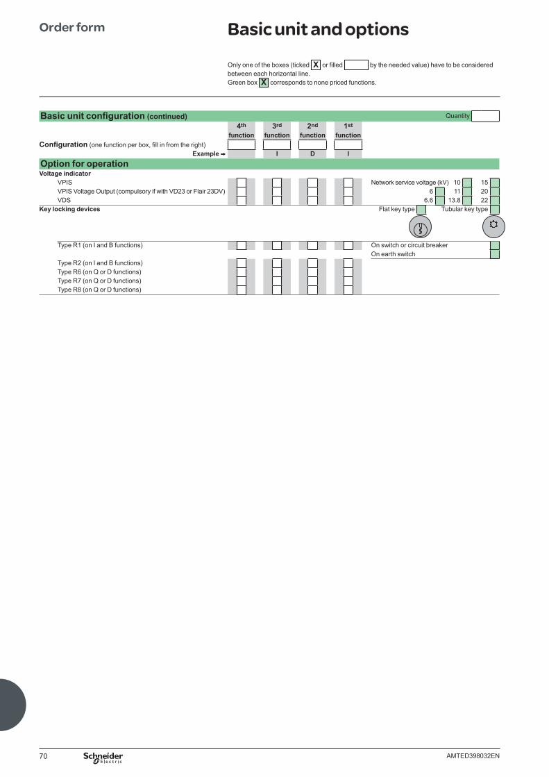
70 AMTED398032EN
Order form Basic unit and options
Only one of the boxes (ticked X or fi lled by the needed value) have to be considered between each horizontal line. Green box X corresponds to none priced functions.
Basic unit confi guration (continued) Quantity4th 3rd 2nd 1st
function function function functionConfi guration (one function per box, fi ll in from the right)
Example V I D I Option for operationVoltage indicator
VPIS Network service voltage (kV) 10 15VPIS Voltage Output (compulsory if with VD23 or Flair 23DV) 6 11 20VDS 6.6 13.8 22
Key locking devices Flat key type Tubular key type
Type R1 (on I and B functions) On switch or circuit breaker On earth switchType R2 (on I and B functions)Type R6 (on Q or D functions)Type R7 (on Q or D functions)Type R8 (on Q or D functions)
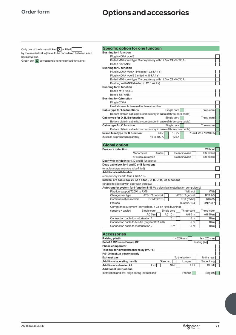
71AMTED398032EN
Specifi c option for one functionBushing for I function
Plug in 400 A type BBolted M16 screw type C (compulsory with 17.5 or 24 kV-630 A)Bolted 5/8" ANSI
Bushing for D functionPlug in 200 A type A (limited to 12.5 kA 1 s)Plug in 400 A type B (limited to 16 kA 1 s)Bolted M16 screw type C (compulsory with 17.5 or 24 kV-630 A)Bushing well ANSI (limited to 12.5 kA 1 s)
Bushing for B functionBolted M16 type CBolted 5/8" ANSI
Bushing for Q functionPlug in 200 AHeat shrinkable terminal for fuse chamber
Cable type for I, Ic functions Single core Three-core Bottom plate in cable box (compulsory in case of three-core cable)
Cable type for D, B, Bc functions Single core Three-core Bottom plate in cable box (compulsory in case of three-core cable)
Cable type for O function Single core Three-core Bottom plate in cable box (compulsory in case of three-core cable)
In and fuse type for Q function 6 kV 10 kV 12/24 kV & 10/100 A(fuses to be procured separately) 16 to 100 A 125 A
Global optionPressure detection Without
Manometer Arabic Scandinavian Standard or pressure switch Scandinavian StandardDoor with window (for I, D and B functions)Deep cable box for I and D or B functions(enables surge arrestors to be fi tted)Additional earth busbar(compulsory if earth fault > 6 kA 1 s)Internal arc cable box 20 kA 1 s for I, D, B, O, Ic, Bc functions(unable to coexist with door with window) Autotransfer system for I function I (48 Vdc electrical motorization compulsory)
Fixation support T200 I to RM6 Without WithChangeover type ATS 1/2 network ATS 1/2 genset BTA 2/3 Communication modem GSM/GPRS FSK (radio) RS485Protocol IEC101/104 DNP3/IPCurrent measurement (only cables, if CT on RM6 bushings)sensors + cables Single core Single core Three-core Three-core
AC 5 m AC 10 m AH 5 m AH 10 mConnection cable to motorization 1 3 m 5 m 10 mConnection cable to bus tie (only for BTA 2/3) 5 m 10 mConnection cable to motorization 2 3 m 5 m 10 m
AccessoriesRaising plinth h = 260 mm h = 520 mmSet of 3 MV fuses Fusarc CF Rating (A)Phase comparatorTest box for circuit breaker relay (VAP 6)PS100 backup power supplyExhaust gas To the bottom To the rearAdditional operating handle Standard Longer Super longAdditional extension kit 1 fct 3 fct 4 fct DE MtAdditional instructions Installation and civil engineering instructions French English
Order form Options and accessories
Only one of the boxes (ticked X or fi lled by the needed value) have to be considered between each horizontal line. Green box X corresponds to none priced functions.

72 AMTED398032EN
Notes


AMTED398032EN 05-2012
As standards, specifi cations and designs change from time to time, please ask for confi rmation of the information given in this publication.
Design: Schneider Electric Industries SASPhotos: Schneider Electric Industries SASPrinted: Altavia Connexion - Made in France
335, rue Joseph Monier CS 30323 F - 92506 Rueil Malmaison Cedex (France) Tél. : +33 (0)1 41 29 70 00RCS Nanterre 954 503 439 Capital social 896 313 776 €www.schneider-electric.com
Schneider Electric Industries SAS
AR
T936
43 ©
Sch
neid
er E
lect
ric In
dust
ries
SA
S -
All
right
s re
serv
ed
This document has been printed on recycled paper
10-31-1247


![Demand Side Management of Electricity Aiming to Minimize ... · Consumer). For this objective, were used data from CELESC - Distributor of Santa Catarina, Brazil [7]. TABLE I: DEMAND](https://static.fdocuments.us/doc/165x107/5f6553a2bfdf06794120d147/demand-side-management-of-electricity-aiming-to-minimize-consumer-for-this.jpg)