
Ring and Peg Simulation for Minimally Invasive Surgical Robot
94
University of Nebraska - Lincoln DigitalCommons@University of Nebraska - Lincoln Mechanical (and Materials) Engineering -- Dissertations, eses, and Student Research Mechanical & Materials Engineering, Department of 4-2018 Ring and Peg Simulation for Minimally Invasive Surgical Robot Evan Brown University of Nebraska - Lincoln, [email protected] Follow this and additional works at: hps://digitalcommons.unl.edu/mechengdiss Part of the Biomechanical Engineering Commons , Biomedical Devices and Instrumentation Commons , and the Surgery Commons is Article is brought to you for free and open access by the Mechanical & Materials Engineering, Department of at DigitalCommons@University of Nebraska - Lincoln. It has been accepted for inclusion in Mechanical (and Materials) Engineering -- Dissertations, eses, and Student Research by an authorized administrator of DigitalCommons@University of Nebraska - Lincoln. Brown, Evan, "Ring and Peg Simulation for Minimally Invasive Surgical Robot" (2018). Mechanical (and Materials) Engineering -- Dissertations, eses, and Student Research. 138. hps://digitalcommons.unl.edu/mechengdiss/138
Transcript of Ring and Peg Simulation for Minimally Invasive Surgical Robot
University of Nebraska - LincolnDigitalCommons@University of Nebraska - LincolnMechanical (and Materials) Engineering --Dissertations, Theses, and Student Research
Mechanical & Materials Engineering, Departmentof
4-2018
Ring and Peg Simulation for Minimally InvasiveSurgical RobotEvan BrownUniversity of Nebraska - Lincoln, [email protected]
Follow this and additional works at: https://digitalcommons.unl.edu/mechengdiss
Part of the Biomechanical Engineering Commons, Biomedical Devices and InstrumentationCommons, and the Surgery Commons
This Article is brought to you for free and open access by the Mechanical & Materials Engineering, Department of at DigitalCommons@University ofNebraska - Lincoln. It has been accepted for inclusion in Mechanical (and Materials) Engineering -- Dissertations, Theses, and Student Research by anauthorized administrator of DigitalCommons@University of Nebraska - Lincoln.
Brown, Evan, "Ring and Peg Simulation for Minimally Invasive Surgical Robot" (2018). Mechanical (and Materials) Engineering --Dissertations, Theses, and Student Research. 138.https://digitalcommons.unl.edu/mechengdiss/138
RING AND PEG SIMULATION FOR MINIMALLY INVASIVE SURGICAL ROBOT
By
Evan Brown
A THESIS
Presented to the Faculty of
The Graduate College at the University of Nebraska
In Partial Fulfilment of Requirements
For the Degree of Master of Science
Major: Mechanical Engineering and Applied Mechanics
Under the Supervision of Professor Shane Farritor
Lincoln, Nebraska
April 2018

RING AND PEG SIMULATION FOR MINIMALLY INVASIVE SURGICAL ROBOT
Evan Brown, M.S.
University of Nebraska, 2018
Adviser: Shane Farritor
Surgical procedures utilizing minimally invasive laparoscopic techniques have shown
less complications, better cosmetic results, and less time in the hospital than conventional
surgery. These advantages are partially offset by inherent difficulties of the procedures which
include an inverted control scheme, instrument clashing, and loss of triangulation. Surgical
robots have been designed to overcome the limitations, the Da Vinci being the most widely used.
A dexterous in vivo, two-armed robot, designed to enter an insufflated abdomen with a limited
insertion profile and expand to perform a variety of operations, has been created as a less
expensive, versatile alternative to the Da Vinci.
Various surgical simulators are currently marketed to help with the rigors of training and
testing potential surgeons for the Da Vinci system, and have been proven to be effective at
improving surgical skills. Using the existing simulators as a baseline, the goal of this thesis was
to design, build, and test a ring and peg simulation that emulates the four degree of freedom
minimally invasive surgical robot from UNL. The simulation was created in the virtual reality
software platform Vizard using the python programming language. Featuring imported visual
models and compound simple shape collision objects, the simulation monitors and generates a
metric file that records the user’s time to task completion along with various errors. A
preliminary study was done on the simulation that measured seven participant’s performance on

the simulation over three consecutive attempts. The study showed that participant’s time to
completion and amount of recorded errors decreased across the three trials, indicating
improvement in the robot operation with use of the simulation. The validation study provided
confidence in continued development and testing of the introductory surgical robot simulation
trainer.

ACKNOWLEDGMENTS
I would like to offer thanks to my advisor, Dr. Shane Farritor, for providing me with the
opportunity to work on such an exciting project in such an important field. I will forever
remember your support and generosity in helping me along this path.
I would also like to thank my family for being there for me when I struggled and
celebrating my successes when things worked out. Without you I wouldn’t be where I am today. I
will always be grateful for all your love and support.
1
Table of Contents
Chapter 1. Background 3
1.1 Minimally Invasive Surgery 4
1.1.1 Laparoendoscopic Single Site Surgeries 4
1.1.2 Robotic Laparoendoscopic Single Site Surgeries 5
1.1.3 Da Vinci Surgical® System 6
1.1.4 UNL Minimally Invasive Surgical Robot 7
1.2 Existing Simulator Technologies 8
1.2.1 dV-Trainer 8
1.2.2 Da Vinci Skills Simulator 9
1.2.3 Robotic Surgery Simulator (Simulated Surgical Systems LLC) 10
1.3 Programming Technology 11
1.3.1 Vizard 11
1.3.2 Python 11
Chapter 2. Motivation 12
2.1 Training Surgical Skills 12
2.2 Metrics to Measure Progress/Proficiency 13
Chapter 3. Solution 14
3.1 Visual Modeling 15
3.2 Collision Modeling 17
3.3 Linking and Grabbing 18
3.4 Movement 20
3.4.1 Cyclic Coordinate Descent 21
3.4.2 Arm Motion 24
3.4.3 Global Positioning 24
3.5 User Controls 26
3.5.1 Geomagic Touch 26
3.5.2 Program Initialization 28
3.5.3 Intra Program Functionality 31
3.6 Graphical User Interface 33
3.6.1 Labeling Elements 33
3.6.2 Temporary Messages 33

2
3.7 Metrics 34
3.7.1 Collisions 34
3.7.3 Instrument Collision 35
3.8 Ending the Simulation 38
3.8.1 Simulation Types 38
Chapter 4. Results 41
4.1 Simulation Evaluation Study 41
4.2 Results of the Study 42
Chapter 5. Conclusion 44
Chapter 6. Future Work 45
References 47
APPENDIX A. Simulation Code 51
APPENDIX B. Study Results Table 88

3
List of Figures
Figure 1.1 Laparoendoscopic Single Site Surgery Through Gelport 4
Figure 1.2 Da Vinci Surgical® System Control and Bedside Modules 6
Figure 1.3 Minimally Invasive Surgical Robot and Labeled Rotational Axis 8
Figure 1.4 dV-Trainer Surgical Training Console 9
Figure 1.5 Robotic Surgery Simulator Surgical Training Console 11
Figure 3.1 Vizard Generated Visual Models 15
Figure 3.2 Imported Visual Models for the Robot 16
Figure 3.3 Generated Collision Models for the Robot 17
Figure 3.4 Ring and Peg Visual and Collision Models 18
Figure 3.5 One Cycle of the CCD Method 23
Figure 3.6 Geomagic Touch Haptic Controllers 26
Figure 3.7 Program Initialization Forearm Choice Dialog Box 28
Figure 3.8 Program Initialization User Name Input Prompt 28
Figure 3.9 Monopolar Cautery Forearm Visual and Collision Models 29
Figure 3.10 Environment with Vertical Peg Box Added 30
Figure 3.11 Standard Viewing Window for Sandbox Simulation Choice 31
Figure 3.12 Torus Position Coloring 35
Figure 3.13 Collision Error Visual Feedback 36
Figure 3.14 Simulation Ending Screen 40
Figure 4.1 Time Taken Per Trial - Ring and Peg Simulation 42
Figure 4.2 Average Errors Per Trial - Ring and Peg Simulation 43

4
Chapter 1. Background
1.1 Minimally Invasive Surgery
1.1.1 Laparoendoscopic Single Site Surgeries
Laparoendoscopic single site (LESS) surgical operations are characterized by their
consolidation of multiple ports into a single incision site as well as the use of laparoscopic tools.
LESS procedures are used in a wide variety of treatments including hysterectomies,
nephrectomies and gastrointestinal surgeries. Variations of the single site surgery include
threading the instruments through a single incision in the skin, or alternatively, through a port
that allows insufflation through a gel like material, the setup of which can be seen in Figure 1.1.
Figure 1.1 Laparoendoscopic Single Site Surgery Through Gelport
(Jerrold, 2015)
Morbidity was decreased in LESS procedures compared to conventional surgery, due to
less average wound complications and reduced time in the hospital (Markar, 2014) (Rink, 2015).
LESS procedures also had better recorded cosmetic results, including less scarring (Leo, 2016).
5
A single port brought some challenges along with the benefits: instrumental clashing, an
inverted control scheme, and loss of triangulation, to name a few. Instrumental clashing occured
when the surgical tools are sent through a port with limited space, causing the tools to potentially
impact or interfere with one another, inhibiting the surgeon's control. Inverted control scheme is
the manner in which the tool’s end effectors mirror the motion of the surgeon; as the surgeon’s
hand moves right, the tip moves left. The ability to visualize three dimensional images from a
two-dimensional scope images is an additional skill needed to successfully perform minimally
invasive LESS procedures (Nugent, 2013). In an effort to combat some of the limitations
inherent to LESS procedures, robotic platforms have been designed and deployed for in vivo
surgeries.
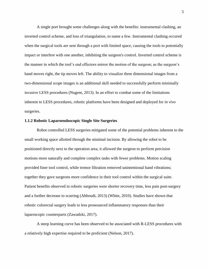
1.1.2 Robotic Laparoendoscopic Single Site Surgeries
Robot controlled LESS surgeries mitigated some of the potential problems inherent to the
small working space allotted through the minimal incision. By allowing the robot to be
positioned directly next to the operation area, it allowed the surgeon to perform precision
motions more naturally and complete complex tasks with fewer problems. Motion scaling
provided finer tool control, while tremor filtration removed unintentional hand vibrations;
together they gave surgeons more confidence in their tool control within the surgical suite.
Patient benefits observed in robotic surgeries were shorter recovery time, less pain post-surgery
and a further decrease to scarring (Abboudi, 2013) (White, 2010). Studies have shown that
robotic colorectal surgery leads to less pronounced inflammatory responses than their
laparoscopic counterparts (Zawadzki, 2017).
A steep learning curve has been observed to be associated with R-LESS procedures with
a relatively high expertise required to be proficient (Nelson, 2017).

6
1.1.3 Da Vinci Surgical® System
The Da Vinci surgical platform, developed by Intuitive Surgical, is the most widespread
medical robotic platform in use across the world. The surgical robot is used in a wide variety of
surgeries, including single-site laparoscopic procedures. Boasting a magnified vision system,
wristed instruments with greater precision and dexterity than the human hand, and ergonomically
designed master-slave console system, the Da Vinci is the household name of the robotic
surgical platforms (Intuitive Surgical, 2017). Some drawbacks to the Da Vinci’s design are its
high cost of entry, over a million dollars, as well as its extensive space requirements of its bulky
console and base, meaning it is unable to operate outside the hospital setting. The surgeon
console and patient-side cart can be seen in Figure 1.2.
Figure 1.2 Da Vinci Surgical® System Control and Bedside Modules
(Intuitive Surgical, Inc., 2018)
The complexity in its operation also necessitated extensive education and experience to
achieve proficiency prior to operating on a patient (Ahmed, 2015).
7
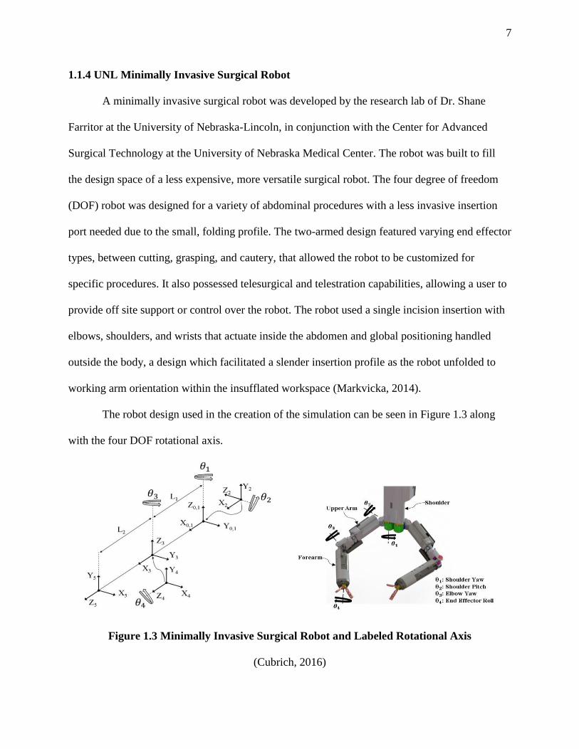
1.1.4 UNL Minimally Invasive Surgical Robot
A minimally invasive surgical robot was developed by the research lab of Dr. Shane
Farritor at the University of Nebraska-Lincoln, in conjunction with the Center for Advanced
Surgical Technology at the University of Nebraska Medical Center. The robot was built to fill
the design space of a less expensive, more versatile surgical robot. The four degree of freedom
(DOF) robot was designed for a variety of abdominal procedures with a less invasive insertion
port needed due to the small, folding profile. The two-armed design featured varying end effector
types, between cutting, grasping, and cautery, that allowed the robot to be customized for
specific procedures. It also possessed telesurgical and telestration capabilities, allowing a user to
provide off site support or control over the robot. The robot used a single incision insertion with
elbows, shoulders, and wrists that actuate inside the abdomen and global positioning handled
outside the body, a design which facilitated a slender insertion profile as the robot unfolded to
working arm orientation within the insufflated workspace (Markvicka, 2014).
The robot design used in the creation of the simulation can be seen in Figure 1.3 along
with the four DOF rotational axis.
Figure 1.3 Minimally Invasive Surgical Robot and Labeled Rotational Axis
(Cubrich, 2016)

8
1.2 Existing Simulator Technologies
A wide range of virtual reality simulators have been used in training to perform
procedures with the Da Vinci Surgical System. It has been shown the the skills obtained on a
training simulator translate into surgical skills and are on par with those acquired in a standard
laboratory setting (Bric, 2014). This provided confidence in the potential benefit of developing a
preliminary training simulation for use with UNL’s minimally invasive robot. Three existing
platforms were compared and analyzed in the development of the simulation: the dV-Trainer, da
Vinci Skills Simulator, and Robotic Surgery Simulator.
1.2.1 dV-Trainer
The dV-Trainer is a tabletop hardware platform created by Mimic Technologies which
can be seen below in Figure 1.4 with the master controllers suspended inside the console
emulator by wires.
Figure 1.4 dV-Trainer Surgical Training Console
(Mimic Technologies, Inc, 2017)

9
Providing the user with several modules, the dV-Trainer allows users to practice and
assess a wide range of necessary robot control skills, including needle control and driving,
suturing, monopolar and bipolar energy use, dissection, knot tying, camera control, and
clutching. The following metrics were used by the platform to judge the proficiency of the user:
economy of motion, instrument collisions, excessive instrument force, procedure time, and
amount of time instruments were out of view. The dV-Trainer showed high face and content
validity with a strong correlation between assessment results from the trainer and recorded
performance from a Da Vinci platform (Perrenot, 2012) (Abboudi, 2013).
1.2.2 Da Vinci Skills Simulator
Developed by Intuitive Surgical the Da Vinci Skills Simulator (DVSS) is add-on program
that is used in conjunction with existing Da Vinci surgical consoles to allow surgeons and
trainees to engage in training exercises to improve their skills. Exercises within the Skills
Simulator cover the following techniques: instrument manipulation, dexterity, camera work,
clutching, additional instrument manipulation, system setting adjustments, needle control, energy
use, dissection, and footswitch use. The exercise results are monitored and reported using
automated metric tracking. Utilizing those metrics, users can track their proficiency and progress
online through PC or smartphone devices. Metrics tracked within the system computer system
included instrument collisions, excessive force, instrument travel distance, instruments moving
out of view, missed targets, time, and a combination of all the metrics into a single aggregate
profile score (Connolly, 2014).

10
1.2.3 Robotic Surgery Simulator (Simulated Surgical Systems LLC)
The Robotic Surgery Simulator (RoSS) is a self-contained piece of hardware built with
force feedback devices and foot pedals that emulate those of the da Vinci robot. The design of
and hardware of the RoSS can be viewed in Figure 1.5.
Figure 1.5 Robotic Surgery Simulator Surgical Training Console
(Simulated Surgical Systems, LLC, 2018)
The RoSS also has the unique feature that allows the trainee to ‘shadow’ a surgeon
through an actual surgical procedure; using haptic feedback and prompts, along with recorded
visuals, the student is walked through the motions of the operation. Reviews assessing the RoSS
have proven it has good face and content validity and that time on the simulator has a positive
influence on the time taken to complete a task on the Da Vinci surgical system (Abboudi, 2013).
11
1.3 Programming Technology
Once the existing simulator systems were reviewed, the methods to developing a unique
virtual reality environment were then researched. Among those examined: V-REP from
Coppelia Robotics and Vizard from WorldViz. In order to be considered, the development
system needed to be compatible with the OpenHaptics software and GeoMagic Touch haptic
devices from 3D Systems, which were used to control the surgical robot. Ultimately, Vizard was
chosen for its flexibile environment creation as well as its robust support for novice creators.
1.3.1 Vizard
Vizard is a virtual reality software platform from WorldViz designed to facilitate the
creation of 3D environments and associated applications. It supports a wide range of image data
types and virtual reality devices, allowing the user to use content from other existing sources
without hassle. Running through the Python language, Vizard’s IDE comes with code
completion and an interactive simulation engine. A built-in physics engine allows for the
simulation of rigid body dynamics and user influenced objects within a virtual reality
environment (WorldViz, 2018). Vizard has been used to generate virtual environments for
various experiments within the medical field. One such experiment, used it to generate a test
platform for an innovative joystick controller design. Within the test platform the joystick
controlled simulated laproscopic tool as the user attempted to perform a peg transfer test (Head,
2012). Another experiment used the software in the creation of a laparoscopic training simulator
used to provide a portable, affordable, metric tracking platform for users (Zahiri, 2017). The
researcher eventually moved that laparoscopic simulator onto Unity, a different VR environment
development platform, which wasn’t explored for use with this project.
Vizard used the Python programming language in its operation.

12
1.3.2 Python
Python is a stable, supported, object-oriented language that uses modules, exceptions
dynamic data types and classes. It runs on many operating systems such as Mac, Windows, and
Unix variants. Python’s current library encompasses the areas of software engineering, internet
protocols, and operating system interfaces like Vizard (Python Software Foundation, 2018).
Vizard also provides a large library of programming examples to help users design their own
environments.
Chapter 2. Motivation
2.1 Training Surgical Skills
A few problems plaguing current training techniques are a decrease in overall surgical
exposure, increasingly technically demanding procedures, and an increase in time and cost
factors involved in instructing future surgeons (Nugent, 2013). Some potential value in a
simulation platform is its ability to provide a concrete baseline with which to test, and certify, the
level of skill of a surgical robot operator. In the same vein, the simulation could be used in
annual retention tests, advanced procedural-based training, or as a warm-up tool prior to a
surgical procedure (Bric, 2016). A study done by Gomez et al. determined that a virtual reality
simulation curriculum was viable for use with the Da Vinci surgical system and improved the
basic skills needed to be a proficient surgical operator of said system (Gomez, 2015). Virtual
reality simulation training has been shown to be a sufficient substitute for laboratory training in
learning robotic surgical skills (Bric, 2014).
Decreasing the cost of training platforms would allow hospitals to provide cheaper
training equipment, which leads to less expensive student fees and additional practice platforms

13
for students. Decreasing the cost would also allow for smoother integration of R-LESS
procedures into the current minimally invasive laparoendoscopic surgery training regime
(University of Nebraska Medical Center, 2018).
Training on a simulation also offers some advantages over that of a traditional laboratory
training method. During training, novices have the potential to accidentaly misuse equipment,
that could damage the relatively expensive surgical robot. The capacity to damage equipment for
the simulation is limited to that of the haptic input devices, and only then through gross
misconduct. The simulation platform also offered additional advantages that couldn’t be found in
a regular laboratory setting in the form of self-recorded concrete metrics that can be used to
measure a trainee’s progress and proficiency.
2.2 Metrics to Measure Progress/Proficiency
Developing the user’s operational skills required metrics that provide quantitative data
for analysis by both evaluator and student. This data would allow both the users and trainers to
gauge the skill level of the user, such that they could then be compared to professional standards.
This process could be similar to what is used in certifying surgeons possess the cognitive and
technical skills needed to perform laparoscopic surgery through the Fundamentals of
Laparoscopic Surgery (Society of American Gastrointestinal and Endoscopic Surgeons, 2017).
The metrics focused on in this simulation are two common metrics examined within the
existing DaVinci simulations, completion of the task time, and various errors to be avoided
during operation. Time to completion is the measured time from the start of the procedure to the
completion of the goal, which, for the simulation, was moving rings from one set of pegs to a
different set of pegs. The real-world analogue of this metric would be the time spent in operation
14
for a surgery. Quicker surgeries result in less time spent under anesthesia, faster recovery, and an
overall better surgical experience for the patient. Therefore, one of the goals of the simulation
was to increase the speed with which the trainee can complete the simulation through practice, as
well as making them more proficient and comfortable with the robot and its operation in a
reduced stress environment.
Another goal of the training simulation was to reduce the number of errors committed
during an operation. Before correction can happen the errors first need to be observed and
recorded, allowing the user to recognize which mistakes they’ve made. The errors targeted by the
simulation are instrument collision, dropped items, and over closing the graspers, all of which
have the potential of damaging the robot or patient during operation.

15
Chapter 3. Solution
3.1 Visual Modeling
The environment for the simulation was created using Vizard’s basic shape generation
capabilities. The vizshape.addBox method provided the simple shape for the peg box using
appropriate dimensional data. A visual grid was created with the addGrid function to provide
some easy to interpret depth to the underlying environment. Without the grid, objects appeared to
float in space, making depth perception difficult. A collision plane was overlaid across the top of
the box attached to the grid to provide a ‘ground’ structure for the pegs to link to and the rings to
rest on when they weren’t being moved by the robot.
Pegs were generated using the vizshape.addCylinder function, and the pegs were made to
extend through the base block, ensuring a seamless visual transition between the two.
Created with the vizshape.addTorus function, the rings were added in a similar manner to
the other elements. The Vizard created environmental models can be viewed in below in Figure
3.1.
Figure 3.1 Vizard Generated Visual Models

16
Stereolithography (stl) files were used to model the robot. The stl files were taken from
the Solidworks files used in the creation of the physical robot to create an accurate representation
within the simulation. After conversion, the files were added to the scene and scaled down to fit
to the environment and positioned appropriately. The entire labeled robot model is shown in
Figure 3.2.
Figure 3.2 Imported Visual Models for the Robot
Hierarchically ordered, the robot was organized to facilitate the relative motion of the
individual components of the arm motion, while also maintaining their relative positioning to the
moving parts above them. The shoulder was assigned as the highest parent, followed by the
upper arms, forearms, and grasper tips as subsequent children, with separate branches existing on
each side of the robot to allow independent motion.

17
3.2 Collision Modeling
Collision for the rings, pegs, forearms, graspers and tips used both singular and
combination of simple shapes to create complex collision objects. Vizard does not support the
visualization of collision objects that are attached to visual objects. This forced each collision
object to be created as a separate object and then later be attached to its rendered counterpart.
This was done to ensure the collision objects have the appropriate size and position, such as
those of the collision models of the robot in Figure 3.3.
Figure 3.3 Generated Collision Models for the Robot
Working around the limitation of the simple collision shapes included in Vizard’s IDE,
building the three-dimensional torus shape for the rings was done by looping the trigonometry of
a circle with the creation of collision spheres through the collideSphere function to create the
appropriate collision object. The loop ran from 0 to 360 degrees at five-degree increments with
the radius of each sphere matching that of the rings. Each individual sphere was assigned to a
single node so they were all treated as a singular object, moving with static relative positioning.
18
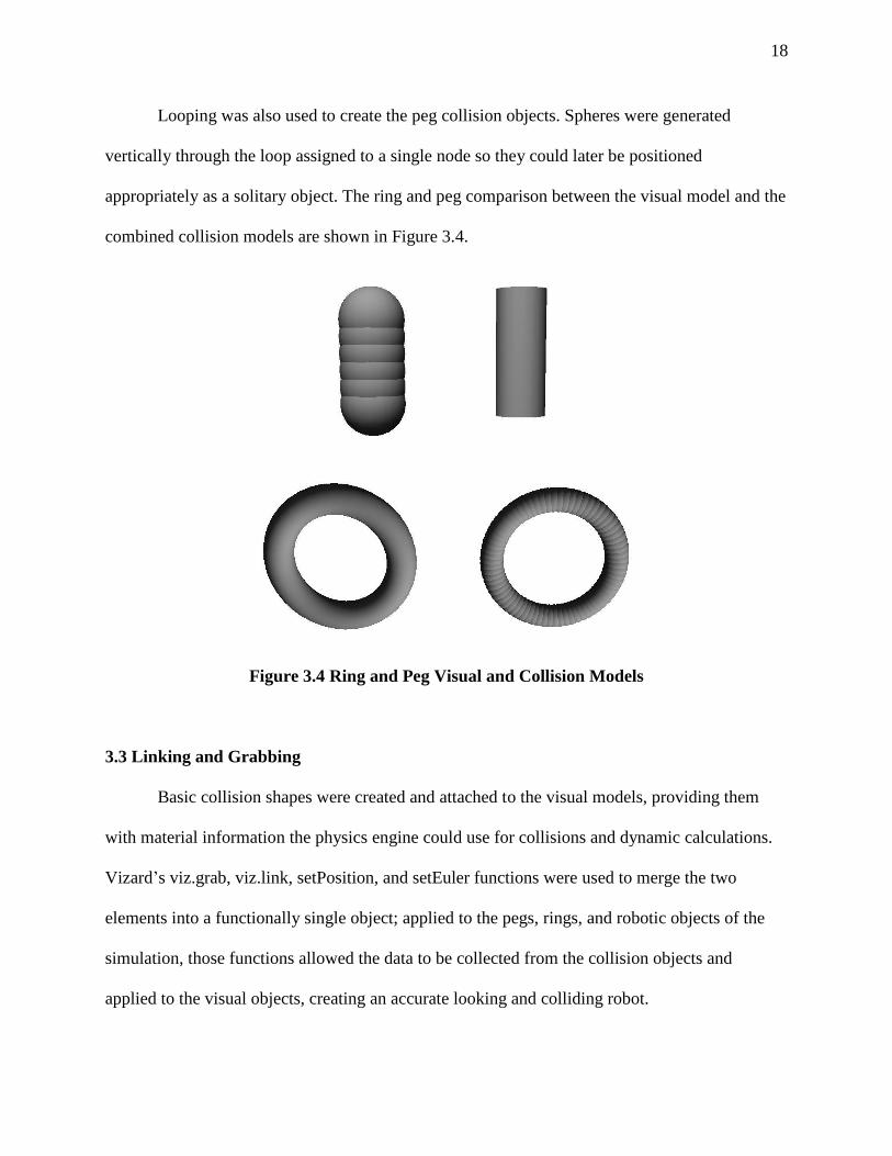
Looping was also used to create the peg collision objects. Spheres were generated
vertically through the loop assigned to a single node so they could later be positioned
appropriately as a solitary object. The ring and peg comparison between the visual model and the
combined collision models are shown in Figure 3.4.
Figure 3.4 Ring and Peg Visual and Collision Models
3.3 Linking and Grabbing
Basic collision shapes were created and attached to the visual models, providing them
with material information the physics engine could use for collisions and dynamic calculations.
Vizard’s viz.grab, viz.link, setPosition, and setEuler functions were used to merge the two
elements into a functionally single object; applied to the pegs, rings, and robotic objects of the
simulation, those functions allowed the data to be collected from the collision objects and
applied to the visual objects, creating an accurate looking and colliding robot.
19
Pegs were cemented to the base grid by attaching the collision models to the grid using
links, after which they were moved to the correct position by the setOffset function. Linking
made it so the base grid’s, or source object’s, position and rotation were applied to the pegs, the
destination objects, creating immovable pegs needed for the environment.
CombineTorus was the function used to set the position and rotation of the visual tori to
their weighted collision counterparts. Set to update every frame, the function continuously
overlayed the ring to the looped spheres by applying the collision tori’s Euler and position data
to the visual tori.
The forearms and grasper arms were assigned to specific positions relative to their parent
models by a function, LockDownPosition, that was called every frame. This allowed the gravity
to be a nonzero value while keeping the collision objects from free falling. During the updates
the visual models were also assigned the rotational Euler values from their collision counterparts,
overlaying the two within the simulation environment. Due to physical limitations, the rotational
values for the arms needed to be limited; by checking, and capping, the turning values, the
program was able to match the robot's limitations.
The grasper tip’s two components were combined in much the same way as the forearms,
differing only through the additional constraint of pairing one tip’s rotation value to its
counterpart’s so that they open and close at the same rate and degree. Limits were also placed on
the tips so they wouldn’t open or close too far.
Picking up the rings was done by introducing initialized links between invisible turn
spheres, which were located at the rotation axis of the forearm tips and the collision objects of
the rings. All the involves nodes were enabled for collision events, allowing collisions to be
reported if two nodes intersect over the course of the simulation.

20
Collisions were flagged to generate collision lists for each of the tips of the individual
forearms, as well as those of the tori and robot arms. Those lists contained all the intersecting
nodes during that frame of the simulation. If the lists of both the tips of a single forearm side
contain a ring, then the initialized blank grab link is removed and a new link is instantiated,
fixing the relative position of the ring to that side's turn sphere. While the position is locked, the
link transfers the rotation of the link sphere onto the torus, allowing for wrist twist of the robot to
be applied to the placement object. The link can only be created if the grasper in question is
being closed through a binary grabTorusLock global value that updates as true every second and
is set as false when the graspers are closing. This lock prevents the user from nudging the rings
with the grasper and unintentionally creating a link.
Before a user can pick up objects they first must be able to control and position the robot
arms. This was done by calculating the kinematic positioning of the tips before applying forces
to the collision objects of the robot to move the arms into the correct position. The kinematics
calculations were done through cyclic coordinate descent.

21
3.4 Movement
Calculating the correct arm positioning for the robot was first attemped with a direct
inverse kinematic solution. That process failed due to some inconsistencies in Vizard's rotational
framework. Instead the kinematics within the simulation used the cyclic coordinate descent
method to determine arm positioning.
3.4.1 Cyclic Coordinate Descent
Cyclic coordinate descent (CCD) is a mathematical method used to find the solution to
inverse kinematic solutions of robotic linkages and rotations. Answers from this method
provided an angular solution for the linkages to a desired end position. First conceived by Wang
and Chen, CCD works by minimizing the angular difference of the vectors between the current
link and end effector position, and the desired position (Wang, Chen, 1991).
Representative vectors were created so that the method could calculate the rotational
Euler values of the vectors for the desired end positions which were then transferred to the
modeled arms, allowing rapid calculation as well as realistic, gradual motion.
To solve for the rotation needed to move each vector into the correct position the
definition of the dot product was used.
𝑎 ∙ 𝑏 = |𝑎||𝑏|cos(𝜃)
Substituting in the appropriate vectors and solving for 𝜃 gives
𝜃 = 𝑐𝑜𝑠−1 ((𝑝𝑒 − 𝑝𝑐) ∙ (𝑝𝑡 − 𝑝𝑐)
|𝑝𝑒 − 𝑝𝑐||𝑝𝑡 − 𝑝𝑐|)
The simulation used the function vizmat.AngleBetweenVector to automate these
calculations of the angles between vectors in degrees. This was applied to the vector linking the
point’s desired end position 𝑝𝑡 and the current rotational axis 𝑝𝑐, and the vector for the current
tip position 𝑝𝑒 and the current rotational axis𝑝𝑐.

22
Using the calculated 𝜃, the current end position 𝑝𝑒, and the rotational axis 𝑝𝑐,
trigonometry was used to rotate the vector, minimizing the error between the current end position
𝑝𝑒 and the desired end position 𝑝𝑡.
𝑝𝑒𝑥𝑖+1 = (𝑝𝑒𝑥
𝑖 −𝑝𝑐𝑥𝑖 ) cos(𝜃) − (𝑝𝑒𝑧
𝑖 −𝑝𝑐𝑧𝑖 ) sin(𝜃) + 𝑝𝑐𝑥
𝑖
𝑝𝑒𝑧𝑖+1 = (𝑝𝑒𝑧
𝑖 −𝑝𝑐𝑧𝑖 ) cos(𝜃) + (𝑝𝑒𝑥
𝑖 −𝑝𝑐𝑥𝑖 ) sin(𝜃)+𝑝𝑐𝑧
𝑖
These calculations were simplified using the setEuler function and started with at the
elbow joint. Once the elbow joint was rotated the rotation axis 𝑝𝑐 was moved to the shoulder
joint for the next calculation, giving two new vectors. Repeating the minimization process for the
new vector the rotational axis 𝑝𝑐 was then moved back to the elbow, restarting the cycle.
Checks were necessary to monitor the current orientation of the parts to ensure the
vectors rotated in the correct direction. The CyclicCoordDes function handled both the upper
arm and grasper vectors, finding the x, y, and z Euler values for the upper arm as well as the x
and z Euler values for the forearm. This is congruent to that of the degrees of freedom present in
each of the two joints so the vector’s rotation matched that of the robot’s potential range of
motion.
Iterating this vector rotational process minimizes the error between the end effector and
the desired end position, and ultimately provides the link orientations required to converge the
end effector to the desired end position. One cycle of this iterative process can be seen in Figure
3.5.

23
Figure 3.5 One Cycle of the CCD Method

24
Once calculated, Euler values were then assigned to global theta variables and passed to
the MoveArms function which rotated the robot models into the same configuration as that of the
representative vectors.
3.4.2 Arm Motion
After the desired angles were calculated, the collision boxes needed to be rotated until the
robot model’s position matched that of the representative vectors. Forces were applied to the
physics-based collision objects for the forearm and upper arm, simultaneously rotating both into
the correct position. Stronger forces were used when the current angle was distant from the
desired angle for responsive control. Damping forces were required to prevent the rotation from
overshooting and provided smoother motion to the robot’s path, slowing the robot down as the
current position approached the desired position. Constantly checked, robot model Euler values
self corrected toward the desired vector values, even in the event of quickly changing values.
To create smooth movements in the robotic model the most current ten theta values
recorded were averaged. This created a drifting mean value that prevented any potential spike in
the vector motion from applying to the robotic motion. This feature created a slight delay
between user input and robotic output.
3.4.3 Global Positioning
On the surgical robot, a global positioning arm allowed for controlled rotation, both
within the patient and during the insertion procedure. For the simulation, the global positioning
arm allowed for an additional joint of rotation, creating a larger operating space, while also
allowing the user to more easily focus on an area of interest. In the TiltShoulderCheck function,

25
the position values for the tip position were tested so that if the average values between the left
and right arms exceeded a threshold value, the shoulder rotated, letting the user determine the
desired operating position of the screen. This rotation had a thirty degree maximum deviation
from the starting position. The rotation was restricted to prevent the robot from injuring a patient
by twisting outside the safe operating space and was likewise constrained in the simulation. The
arms across from the rotating direction had to also surpass a minimum value before the motion is
allowed; this was done to help prevent unintended rotations. This meant that in order to move the
left, the right arm’s horizontal value was checked as well as the average value of both arms. The
same was true for right, but the left arm’s horizontal value was checked instead.
26
3.5 User Controls
3.5.1 Geomagic Touch
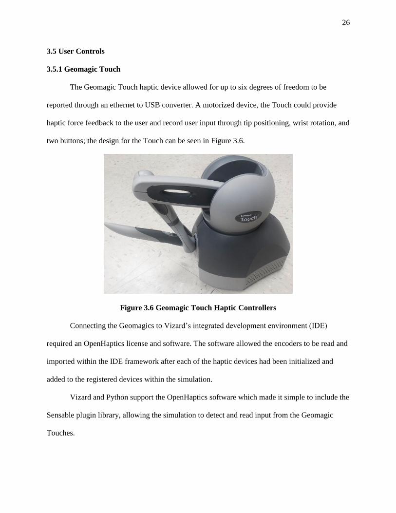
The Geomagic Touch haptic device allowed for up to six degrees of freedom to be
reported through an ethernet to USB converter. A motorized device, the Touch could provide
haptic force feedback to the user and record user input through tip positioning, wrist rotation, and
two buttons; the design for the Touch can be seen in Figure 3.6.
Figure 3.6 Geomagic Touch Haptic Controllers
Connecting the Geomagics to Vizard’s integrated development environment (IDE)
required an OpenHaptics license and software. The software allowed the encoders to be read and
imported within the IDE framework after each of the haptic devices had been initialized and
added to the registered devices within the simulation.
Vizard and Python support the OpenHaptics software which made it simple to include the
Sensable plugin library, allowing the simulation to detect and read input from the Geomagic
Touches.
27
The simulation utilized the same method of acquiring user input as that of UNL’s
miniature surgical robot, using two linked Geomagic Touch haptic devices to get arm
positioning. Once the device’s tip position was read, the data was scaled to fit within the desired
workspace of the program. After scaling, the data sets containing the positional data were
assigned to the nodes representing desired position for use with CCD. The CCD calculations are
then run an iteration every frame to get the desired Euler angles to be assigned to the collision
objects. The buttons and wrist twist from the Geomagics were checked to see if the grasper tips
should be twisting, opening, or closing. All methods present operated for each of the two
Geomagic’s, applying to the left and right sides of the robot, allowing independent motion within
the simulation.

28
3.5.2 Program Initialization
The starting parameters provided to be decided on by the user included the forearm used
for the left arm of the robot, the inclusion of a vertical pegbox, and the type of simulation.
Through vizdlg.AskDialog commands, choice boxes were generated so the user could select
from among the options within the interface using the mouse cursor; said boxes can be seen
below in Figure 3.7.
Figure 3.7 Program Initialization Forearm Choice Dialog Box
When cancel was chosen that getInput function read an unaccepted value and
reinstantiated that choice box.
A username was recorded in the simulation using a keyboard prompt through the
vizinput.input command seen in Figure 3.8.
Figure 3.8 Program Initialization User Name Input Prompt

29
The username was then assigned to the metrics text file recorded at the end of the
program and, along with the tallied progress and error values, printed into a folder generated for
each username with the name and date attached to the file. The user inputs were nested so that
the next choice would not appear until the previous section has a recorded value.
The two types of forearms included in the program were the cautery forearm and the
standard grasper forearm. The cautery forearm visual and matching collision models are shown
below in Figure 3.9.
Figure 3.9 Monopolar Cautery Forearm Visual and Collision Models
If the grasper was chosen then the cautery forearm’s visual model was removed, along
with all the associated children objects using Vizard’s remove function. The introducing of both
prior to removing one was done to prevent loading errors, whilst supporting a movement
function that worked with both forearm choices.
30
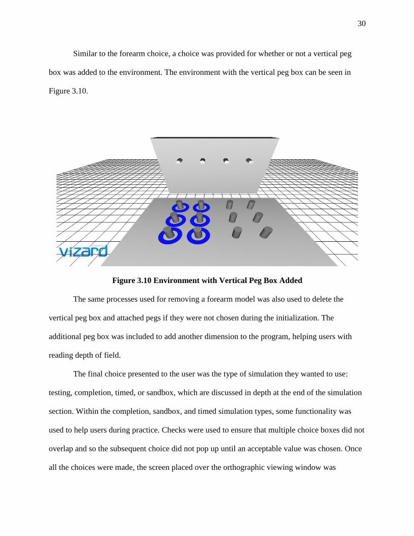
Similar to the forearm choice, a choice was provided for whether or not a vertical peg
box was added to the environment. The environment with the vertical peg box can be seen in
Figure 3.10.
Figure 3.10 Environment with Vertical Peg Box Added
The same processes used for removing a forearm model was also used to delete the
vertical peg box and attached pegs if they were not chosen during the initialization. The
additional peg box was included to add another dimension to the program, helping users with
reading depth of field.
The final choice presented to the user was the type of simulation they wanted to use:
testing, completion, timed, or sandbox, which are discussed in depth at the end of the simulation
section. Within the completion, sandbox, and timed simulation types, some functionality was
used to help users during practice. Checks were used to ensure that multiple choice boxes did not
overlap and so the subsequent choice did not pop up until an acceptable value was chosen. Once
all the choices were made, the screen placed over the orthographic viewing window was

31
removed, allowing the chosen environmental and robot elements to be seen and starting any
necessary timers based on the simulation types.
3.5.3 Intra Program Functionality
Certain simulation types, like sandbox and timed, supported additional functionality that
allowed the user to reset the simulation, manually record their metrics, start and stop the timer, or
unlock the camera.
Buttons and associated functions were created for the user to interact with inside the
program, enabling functions that were only called when an assigned button was clicked through
the mouse cursor. Labels were assigned to the buttons using viz.addText commands. Attached as
a child to the orthographic window, the text remained stationary, independent of any motion
from the robot or camera. The buttons likewise were locked to the Vizard window for similar
reasons. A standard viewing window for the sandbox simulation type is shown in Figure 3.11.
Figure 3.11 Standard Viewing Window for Sandbox Simulation Choice
32
Clicking on the “Reset Simulation” button allowed a user to replace the rings to their
starting position. The end positions for the CCD vectors were likewise replaced to their initial
values along with the position and rotation of the robot’s model.
The “Record Metrics” button in the corner manually called the function that builds a file
with the errors, ring completion, and time to completion values within the simulation up to that
point. Transparency was applied to the text for the record metrics button to keep it discreet.
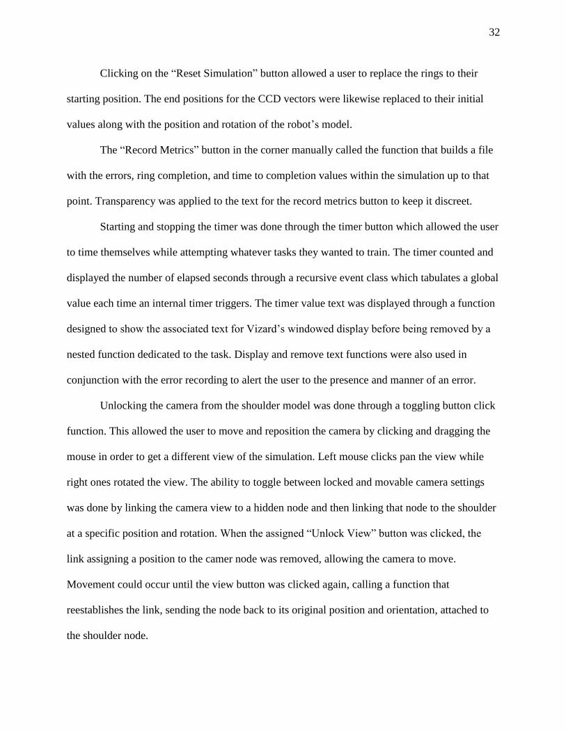
Starting and stopping the timer was done through the timer button which allowed the user
to time themselves while attempting whatever tasks they wanted to train. The timer counted and
displayed the number of elapsed seconds through a recursive event class which tabulates a global
value each time an internal timer triggers. The timer value text was displayed through a function
designed to show the associated text for Vizard’s windowed display before being removed by a
nested function dedicated to the task. Display and remove text functions were also used in
conjunction with the error recording to alert the user to the presence and manner of an error.
Unlocking the camera from the shoulder model was done through a toggling button click
function. This allowed the user to move and reposition the camera by clicking and dragging the
mouse in order to get a different view of the simulation. Left mouse clicks pan the view while
right ones rotated the view. The ability to toggle between locked and movable camera settings
was done by linking the camera view to a hidden node and then linking that node to the shoulder
at a specific position and rotation. When the assigned “Unlock View” button was clicked, the
link assigning a position to the camer node was removed, allowing the camera to move.
Movement could occur until the view button was clicked again, calling a function that
reestablishes the link, sending the node back to its original position and orientation, attached to
the shoulder node.

33
3.6 Graphical User Interface
3.6.1 Labeling Elements
Displaying text elements for the user interface used separate processes for text that
needed to remain displayed on the display window versus text that was only shown for a limited
time. StaticText was the function created to label permanent text elements assigned to user
interface buttons. Vizard’s addText allowed a string of text to be assigned to the orthographic
viewing window. The color, choice, font size and placement variable values were directly
assigned after some experimentation with different layouts. Around some text, outlines were
added to the record metric text to increase legibility against the background, and the text was
made partially transparent to decrease obstruction of the user’s visual field, which can be seen in
the bottom right of Figure 3.11. The same process was also used for the red collision error
feedback text, a temporary message that was only displayed for a small amount of time.
3.6.2 Temporary Messages
Temporary messages, like those for error reporting or displaying the timer value, were
handled through the DisplayText function. Inputting the message string or number, quadrant,
color, size, and time, the function assigned these requisite values to the addText function to be
displayed in the correct manner and position. Vizact.ontimer2 was used so that after the assigned
time ellapsed, a nested function, RemoveText, was called, deleting the displayed text object.
34
3.7 Metrics
3.7.1 Collisions
Feedback and metric recording within the simulation required the examination of the
interaction of individually modeled parts of the robot through collision reporting. Three things
were necessary to detect and interact with collisions through Vizard: collision objects needed to
have detection enabled, a collision event needed to be generated that created a list of nodes
associated with the collision, and finally, the list needed to be checked for intersecting nodes of
interest. Enabling collision was done through enable(viz.COLLIDE_NOTIFY), which, when
combined with viz.COLLIDE_BEGIN_EVENT, allowed Vizard to callback a function whenever
an enabled node collided with another node. After the collision function was called, a list of
intersecting nodes was compiled through the viz.phys.intersectNode command, with the node of
interest as the input. The list could then be checked with if statements, looking for relevant
nodes. After detecting the relevant nodes, customized branches of if statements allowed
programmatic reactions to a variety of collisions, including detecting error collisions as well as
providing visual feedback for ring positioning.
3.7.2 Ring Positioning
Attached to the center of each of the rings was an invisible position sphere with collision
detection enabled but the physics disabled, allowing it to detect intersecting nodes without
colliding and interacting with other collision objects. Each position sphere checks for four
distinct states with the associated ring: around a starter peg, around an ending peg, hovering
above the pegbox, and dropped onto the pegbox without also encircling a peg. While the ring
was around a starter peg, the visual model of said peg was set to blue with a node.color

35
assignment command. Alternatively, if the ring was around an ending peg the color was set to
dark green. Light green was used if the position sphere was not intersecting something on the
ground of the simulation, i.e. gripped and lifted by the robot. Finally, if the peg was lying on the
peg box without surrounding a peg then it was considered a dropped peg and a dropped item
function was called to increment the global variable created to track that metric. Each of the ring
states can be viewed in Figure 3.12.
Figure 3.12 Torus Position Coloring
To prevent multiple errors from counting for a single instance of a drop, a lock was
placed that triggered on the initial incrementation with a self-activated timer that prevents
another error from counting for ten seconds. Therefore, every ten seconds a new error will be
recorded if the ring was unable to be picked up in that time.
3.7.3 Instrument Collision
Beyond just checking for dropped rings the simulation also checked for instrument
collision and overclosed grasper tips. Instrument collision occurred when a section of the robot

36
touched another section of the robot. Outside the simulation this could cause damage to the robot
and, although unlikely, inhibit operation. Within the simulation, the parts which touched each
other were highlighted red for a moment to alert the user of the impact and a collision error was
logged.
Figure 3.13 Collision Error Visual Feedback
After three seconds had elapsed, the color was reset back to the originally assigned value for the
affected visual models. Similar to a dropped ring error, a linked timer event prevented multiple
errors from recording from a single collision instance.
3.7.4 Overclose Errors
Overclose errors were logged in the simulation whenever the grasper tips were closed
beyond acceptable limits. When a ring is grabbed the limit is reassigned to the current value of
the grasper. A global variable was used to register the number of attempts to close the grasper
while it was at a closing limit. Once the variable passed a threshold the error count for over-
closing is incremented and a message was sent through the temporary text function to announce
the error and on which side the error occurred.
37
3.7.5 Timer
The simulation used Vizard’s internal timer for stopwatch and timed testing utilities.
Toggling was needed for the user-controlled stopwatch inside the sandbox simulation type. It
was made with a self-referential function which incremented the global variable timeValue every
second the timer was toggled ‘on’ and remained constant when the timer was ‘off’. The global
variable, timerToggle, was initialized to a zero value which was then incremented every time the
timer button is clicked; if the value was incremented to two the value is reset to zero. This
allowed the user to continuously click the button, turning the timer ‘on’ and ‘off’.
Unlocking and relocking the camera used the same toggling method.
3.7.6 Metrics File
Metrics were tabulated throughout the course of the simulation, recording the over-close,
collision, and dropped items errors, as well as the elapsed time and completed tori at the time of
reporting. Users were allowed to trigger the documentation of the metrics through the use of the
provided button during appropriate simulation types. File writing was done through integrated
Python write/read commands with files and folders. The timer value was segmented into minutes
and seconds for easier reading and recording. The metrics were stored in a folder for each user
based on the username entered at the beginning of the simulation. If no such folder exists then a
new folder was created with that username. The file was date stamped and checked for an
existing identical file. If such a file existed then the new file was tagged with a number at the end
of the file, repeated for each subsequent file, allowing each discrete instance of recorded data to
be viewed later regardless of the number of metric text files generated.

38
3.8 Ending the Simulation
3.8.1 Simulation Types
Four simulation types were included in the simulation: sandbox, time limit, completion,
and testing. Sandbox allowed the users the full range of intra-program functionality including
timer, resetting the positioning of the collision objects, camera viewport motion, and metric
recording. Time limit had all the same functionality except for the timer. It hid the displayed
timer and button, instead starting it upon selection of the simulation that then counted to a preset
limit before ending the simulation. A visual countdown was generated when the timed simulation
had ten seconds remaining, warning the user of the impending closing which was also used in the
testing simulation type. The completion simulation type runs until all six rings were around an
ending peg, at which point the ending screen was called and the metrics were recorded but also
allowed the user to reset the simulation and record metrics manually. Similar to sandboxm all the
user functionality was provided within the completion simulation choice. Testing had all the user
functionality removed, providing a common baseline for each test. The simulation ended within
the testing type and the metrics recorded if the six rings were detected around the ending pegs or
if the four-minute timer expires.
3.8.2 End Conditions
Ending the simulation happened when an end condition was met, triggering the end
screen and associated end of the simulation functions. The conditions to be met for ending the
simulation were dependent on which type of simulation had been selected. For completion and
testing, the ring position was checked, and if the number of rings around ending pegs matched
39
the preset value for completed rings, then the simulation ending function was called. Timed used
the global timer variable reaching the threshold of four minutes as the condition the end
simulation function checked for ending the program. Testing also used the four-minute threshold
through the timer value as a limiting factor for the user to restrict the time taken on a single
attempt. Otherwise the simulation was ended once all six of the rings were recorded as encircling
the ending pegs.

40
3.8.3 End Screen
The check ending function was called once every second on an internal Vizard timer and
only called the ending functions if an end state for that simulation type had been reached. Once
the end state occurred the completed screen was placed over the program window and the
metrics were recorded to their labeled text file. The completed screen function set the end
simulation state to true which stopped the program from checking for the ending. A sky-blue
overlay was then applied whilst simultaneously turning off the rendering of the main scene in
Vizard, removing all the visible and collision models from the view window. The StaticText
function was then called, informing the user that the simulation was completed and letting them
know to restart the program to run the simulation again. The complete ending screen can be seen
in Figure 3.14.
Figure 3.14 Simulation Ending Screen

41
Chapter 4. Results
4.1 Simulation Evaluation Study
In a collaboration with the University of Nebraska Medical Center (UNMC) a
preliminary study was created to validate that repeated uses of simulation would improve new
users’ operating skills. The study was evaluated under UNMC’s IRB with study identification
number #087-18-EX. The Center for Advanced Surgical Technology’s facility was used to
conduct the study. Medical students were recruited through an emailed link to an online survey,
where they signed up for a fifteen-minute time slot. After a short introduction to the project,
seven UNMC medical students attempted to complete the simulation in testing mode three
consecutive times, pausing only to reset the simulation and verify that the results file had been
reported. Results were recorded using the built-in methods of the simulation and were assigned
to numbered identifications to preserve confidentiality for the subjects.
42
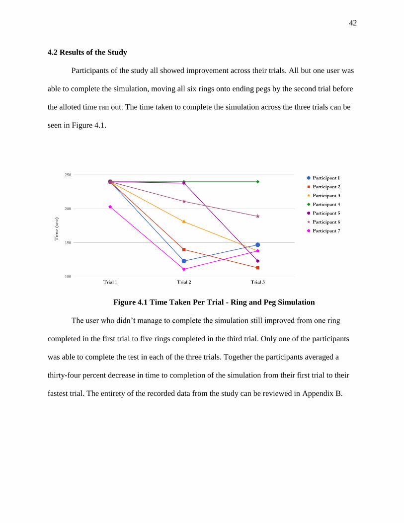
4.2 Results of the Study
Participants of the study all showed improvement across their trials. All but one user was
able to complete the simulation, moving all six rings onto ending pegs by the second trial before
the alloted time ran out. The time taken to complete the simulation across the three trials can be
seen in Figure 4.1.
Figure 4.1 Time Taken Per Trial - Ring and Peg Simulation
The user who didn’t manage to complete the simulation still improved from one ring
completed in the first trial to five rings completed in the third trial. Only one of the participants
was able to complete the test in each of the three trials. Together the participants averaged a
thirty-four percent decrease in time to completion of the simulation from their first trial to their
fastest trial. The entirety of the recorded data from the study can be reviewed in Appendix B.

43
The number of errors committed also decreased as the participants became more
comfortable with the system. This occurred both between trial one and two and trial two and
three, with the steepest decrease coming between the first and second trial. These trends can be
seen in Figure 4.2 which shows the average errors of the participants in each of the trials.
4.2 Average Errors Per Trial - Ring and Peg Simulation
Taking a one tailed test of the statistical significance between the first and last trials
showed that, with significance level of five percent, the users showed statistically significant
improvement in all three errors and time time to completion. The results of the significance test
can be seen in Appendix B.
44
Chapter 5. Conclusion
Presented within this thesis was the creation of a simulation built to introduce users to the
operation of a two armed minimally invasive surgical robot. The simulation was designed with
the likeness and motion capacity of the robot as well as the input method. Metrics to be
examined were taken from a literature review on existing surgical simulators created for the Da
Vinci surgical system and included time to task completion, dropped items, instrument collision,
and overclose errors.
In an IRB approved study, seven UNMC medical students were asked to operate the
simulation through three consecutive trials to examine how their performance changed across
attempts. All of the users showed improvements between the first and final attempts, decreasing
the time taken to completion as well as the amount of recorded errors. Both the errors and the
time to completion showed statistically significant improvements between the first and third
trials. This preliminary study provided confidence in continued exploration and examination of
the simulation system as a viable introductory platform for the surgical robot.

45
Chapter 6. Future Work
While the simulation showed good promise, many improvements could be made going
forward. Additional testing should be done to examine whether training on the simulation helps
improve the performance on the surgical robot. This would help prove the hypothesis that this
training simulation could help ease the training regime needed to obtain mastery over the robotic
platform. Initially a baseline of mastery would be created with the help of an experienced robotic
surgeon operating the surgical robot through a ring and peg challenge. After the baseline was
created, five to ten novice medical school residents would be introduced to the surgical robot and
train on the ring and peg course until they reached the predetermined mastery. After the median
time to achieve mastery had been determined another five to ten medical students would be
introduced to the surgical robot, this time via the simulation. The new set of users would be
allowed to train on the simulation to familiarize themselves with the operation of the robot and
the task of moving the rings until they’d achieved the desired level of mastery. After the
introduction, the group would then be taken to the physical robot to perform on the ring and peg
platform there, moving six rings from designated starting pegs to ending pegs, just like the
simulation. The time to mastery on the robot would then be measured and compared to that of
the initial group, providing a comparison between the pure laboratory robot training and training
done with an introduction through simulation training. This would also allow data to be
generated concerning the face and content validity of the simulation, determining the correlation
between simulation and surgical robot performance.
The design of the University of Nebraska minimally invasive surgical robot has changed
since the creation of the simulation. These changes have not been implemented within the
simulation and would need to be done to keep the operation of the simulation as similar to that of
46
the robot to ensure the accuracy of the simulation. The changes would involve replacing the
visual model files used, altering the collision models accordingly and scaling the positioning
vectors as needed.
Surveys could be helpful to find improvements for the user interface and error reporting
elements, allowing them to be refined to enhance the clarity and usability of the simulation.
A variety of different simulation environments and testing methods could be created to
examine and improve a wider breadth of surgical skills beyond those covered by the ring and peg
exercise. One potential simulation scenario is a pick and place test where the user must pick up
and rotate differently shaped pieces before putting them in appropriate sunken holes on a board.
Foot pedal functionality could also be included in future iterations of the simulation
allowing for cautery testing and metrics. Another additional metric helpful for generating a more
robust data set on the user’s performance would be economy of motion, which looks at how far
the tips of the robot arms move throughout the examination.

47
References
Abboudi, Hamid, et al. “Current Status of Validation for Robotic Surgery Simulators - a
Systematic Review.” BJU International, vol. 111, no. 2, Feb. 2013, pp. 194–205.
doi:10.1111/j.1464-410X.2012.11270.x. Accessed 6 Feb. 2018.
Ahmed, Kamran, et al. “Development of a Standardised Training Curriculum for Robotic
Surgery: A Consensus Statement from an International Multidisciplinary Group of
Experts.” BJU International, vol. 116, no. 1, 2015, pp. 93–101., doi:10.1111/bju.12974.
Bric, Justin, et al. “Current State of Virtual Reality Simulation in Robotic Surgery Training: a
Review.” Surgical Endoscopy, vol. 30, no. 6, June 2016, pp. 2169–2178.
doi:10.1007/s00464-015-4517-y. Accessed 6 Feb. 2018.
Bric, Justin, et al. “Proficiency Training on a Virtual Reality Robotic Surgical Skills
Curriculum.” Surgical Endoscopy, vol. 28, no. 12, Dec. 2014, pp. 3343–3348.
doi:10.1007/s00464-014-3624-5. Accessed 6 Feb. 2018.
Buchs, Nicolas C., et al. “Learning Tools and Simulation in Robotic Surgery: State of the Art.”
World Journal of Surgery, vol. 37, no. 12, Dec. 2013, pp. 2812–2819. doi:10.1007/s00268-
013-2065-y. Accessed 6 Feb. 2018.
Choi, Hyundo, et al. “Surgical Robot for Single-Incision Laparoscopic Surgery.” IEEE
Transactions on Biomedical Engineering, vol. 61, no. 9, Sept. 2014, pp. 2458–2466.
doi:10.1109/TBME.2014.2320941. Accessed 6 Feb. 2018.
Connolly, Michael, et al. “Validation of a Virtual Reality-Based Robotic Surgical Skills
Curriculum.” Surgical Endoscopy, vol. 28, no. 5, May 2014, pp. 1691–1694.
doi:10.1007/s00464-013-3373-x. Accessed 6 Feb. 2018.
Cubrich, Lou P., and Shane M. Farritor. “Design of a Flexible Control Platform and Miniature in
Vivo Robots for Laparo-Endoscopic Single-Site Surgeries.” DigitalCommons@University
of Nebraska - Lincoln, University of Nebraska Lincoln, Dec. 2016,
digitalcommons.unl.edu/mechengdiss/104/.
Gash, K., et al. “Single-Incision Laparoscopic Surgery for Rectal Cancer: Early Results and
Medium-Term Oncological Outcome.” Colorectal Disease, vol. 17, no. 12, Dec. 2015, pp.
1071–1078. doi:10.1111/codi.13034. Accessed 6 Feb. 2018.
Gomez, Pedro, et al. “Development of a Virtual Reality Robotic Surgical Curriculum Using the
Da Vinci Si Surgical System.” Surgical Endoscopy, vol. 29, no. 8, Aug. 2015, pp. 2171–
2179. doi:10.1007/s00464-014-3914-y. Accessed 6 Feb. 2018.
Halvorsen, F., et al. “Virtual Reality Simulator Training Equals Mechanical Robotic Training in
Improving Robot-Assisted Basic Suturing Skills.” Surgical Endoscopy, vol. 20, no. 10,
Oct. 2006, pp. 1565–1569. doi:10.1007/s00464-004-9270-6. Accessed 6 Feb. 2018.
Head, Michael John. “Modular Joystick Design for Virtual Reality Surgical Skills
Training.”DigitalCommons@University of Nebraska - Lincoln, University of Nebraska
Lincoln, 2012, digitalcommons.unl.edu/mechengdiss/46/.
48
Intuitive Surgical. “The Da Vinci® Surgical System.” Da Vinci® Surgery, Oct. 2017,
www.davincisurgery.com/da-vinci-surgery/da-vinci-surgical-system/.
Intuitive Surgical, Inc. “The Da Vinci® Surgical System.” Intuitive Surgical®, 2018,
www.intuitivesurgical.com/products/davinci_surgical_system/.
Lehman, Amy C., et al. “Dexterous Miniature Robot for Advanced Minimally Invasive
Surgery.” Surgical Endoscopy, vol. 25, no. 1, Jan. 2011, pp. 119–123. doi:10.1007/s00464-
010-1143-6. Accessed 6 Feb. 2018.
Leo, C. A., et al. “Initial Experience of Restorative Proctocolectomy for Ulcerative Colitis by
Transanal Total Mesorectal Rectal Excision and Single-Incision Abdominal Laparoscopic
Surgery.” Colorectal Disease, vol. 18, no. 12, Dec. 2016, pp. 1162–1166.
doi:10.1111/codi.13359. Accessed 6 Feb. 2018.
Lerman, Jerrold, et al. “General Abdominal and Urologic Surgery.” Clinical Gate, 5 Feb. 2015,
clinicalgate.com/general-abdominal-and-urologic-surgery/.
Lin, David W., et al. “Computer-Based Laparoscopic and Robotic Surgical Simulators:
Performance Characteristics and Perceptions of New Users.” Surgical Endoscopy, vol. 23,
no. 1, Jan. 2009, pp. 209–214. doi:10.1007/s00464-008-9805-3. Accessed 6 Feb. 2018.
Liu, May, and Myriam Curet. “A Review of Training Research and Virtual Reality Simulators
for the Da Vinci Surgical System.” Teaching & Learning in Medicine, vol. 27, no. 1, Jan.
2015, pp. 12–26. doi:10.1080/10401334.2014.979181. Accessed 6 Feb. 2018.
Lyons, Calvin, et al. “Which Skills Really Matter? Proving Face, Content, and Construct
Validity for a Commercial Robotic Simulator.” Surgical Endoscopy, vol. 27, no. 6, June
2013, pp. 2020–2030. doi:10.1007/s00464-012-2704-7. Accessed 6 Feb. 2018.
Markar, Sheraz, et al. “Single-Incision versus Conventional Multiport Laparoscopic Colorectal
Surgery-Systematic Review and Pooled Analysis.” Journal of Gastrointestinal Surgery,
vol. 18, no. 12, Dec. 2014, pp. 2214–2227. doi:10.1007/s11605-014-2654-6. Accessed 6
Feb. 2018.
Markvicka, Eric John, and Shane M. Farritor. “Design and Development of a Miniature In Vivo
Surgical Robot with Distributed Motor Control for Laparoendoscopic Single-Site Surgery.”
DigitalCommons@University of Nebraska - Lincoln, University of Nebraska-Lincoln, 16
Aug. 2014, digitalcommons.unl.edu/mechengdiss/75/.
Mimic Technologies, Inc. “DV-Trainer®.” Mimic Simulation, 20 Dec. 2017,
mimicsimulation.com/dv-trainer/.
Nelson, Ryan J., et al. “Current Status of Robotic Single‑Port Surgery.” Urology Annals, vol. 9,
no. 3, July 2017, pp. 217–222. doi:10.4103/UA.UA_51_17. Accessed 6 Feb. 2018.
Nugent, Emmeline, et al. “Development and Evaluation of a Simulator-Based Laparoscopic
Training Program for Surgical Novices.” Surgical Endoscopy, vol. 27, no. 1, Jan. 2013, pp.
214–221. doi:10.1007/s00464-012-2423-0. Accessed 26 Feb. 2018.
Palmowski, Joseph, and Shane Farritor. “Mobility, Dexterity, and Insertion Improvements of
Current Miniature In Vivo Robotic Minimally Invasive Surgical Techniques.”

49
DigitalCommons@University of Nebraska - Lincoln, University of Nebraska Lincoln, Dec.
2017, digitalcommons.unl.edu/embargotheses/123/.
Patel, Ankit, et al. “Can We Become Better Robot Surgeons through Simulator Practice?”
Surgical Endoscopy, vol. 28, no. 3, Mar. 2014, pp. 847–853. doi:10.1007/s00464-013-
3231-x. Accessed 6 Feb. 2018.
Perrenot, Cyril, et al. “The Virtual Reality Simulator DV-Trainer Is a Valid Assessment Tool for
Robotic Surgical Skills.” Surgical Endoscopy, vol. 26, no. 9, Sept. 2012, pp. 2587–2593.
doi:10.1007/s00464-012-2237-0. Accessed 6 Feb. 2018.
Python Software Foundation. “General Python FAQ.” Python, 3 Feb. 2018,
docs.python.org/2/faq/general.html.
Reichenbach, Mark A. “Gross Positioning Arm for in Vivo Robotic Surgery.” Digital
Commons@University of Nebraska Lincoln, University of Nebraska Lincoln, 2016,
digitalcommons.unl.edu/embargotheses/96/.
Rink, Andreas, et al. “Single-Incision Laparoscopic Surgery for Colorectal Malignancy-Results
of a Matched-Pair Comparison to Conventional Surgery.” International Journal of
Colorectal Disease, vol. 30, no. 1, Jan. 2015, pp. 79–85. doi:10.1007/s00384-014-2041-5.
Accessed 6 Feb. 2018.
Schout, B. M. A., et al. “Validation and Implementation of Surgical Simulators: a Critical
Review of Present, Past, and Future.” Surgical Endoscopy, vol. 24, no. 3, Mar. 2010, pp.
536–546. doi:10.1007/s00464-009-0634-9. Accessed 6 Feb. 2018.
Scott, Daniel J., and Gary L. Dunnington. “The New ACS/APDS Skills Curriculum: Moving the
Learning Curve out of the Operating Room.” Journal of Gastrointestinal Surgery, vol. 12,
no. 2, Feb. 2008, pp. 213–221. doi:10.1007/s11605-007-0357-y. Accessed 6 Feb. 2018.
Simulated Surgical Systems, LLC. “Robotic Surgery Simulator.” Simulated Surgical Systems:
Digital Agency, 2018, www.simulatedsurgicals.com/ross2.html.
Smith, Roger, et al. “Comparative Analysis of the Functionality of Simulators of the Da Vinci
Surgical Robot.” Surgical Endoscopy, vol. 29, no. 4, Apr. 2015, pp. 972–983.
doi:10.1007/s00464-014-3748-7. Accessed 6 Feb. 2018.
Society of American Gastrointestinal and Endoscopic Surgeons. “FLS Program Description”
Fundamentals of Laparoscopic Surgery, 15 Aug. 2017, www.flsprogram.org/index/fls-
program-description/.
Spana, Gregory, et al. “Is Robotics the Future of Laparoendoscopic Single-Site Surgery
(LESS)?” BJU International, vol. 108, no. 6b, 20 Sept. 2011, pp. 1018–1023.
doi:10.1111/j.1464-410X.2011.10513.x. Accessed 6 Feb. 2018.
Teishima, Jun, et al. “Psychological Factor, Metacognition, Is Associated with the Advantage of
Suturing Techniques Acquired on a Virtual Reality Simulator of Robot-Assisted Surgery.”
International Journal of Urology, vol. 21, no. 3, Mar. 2014, pp. 349–350.
doi:10.1111/iju.12286. Accessed 6 Feb. 2018.
University of Nebraska Medical Center. “Skills Training.” College of Medicine Department of
Surgery, University of Nebraska Medical Center, 2018,

50
www.unmc.edu/surgery/residencies-fellowships/gensurgery-residency/ed-
activities/training/index.html.
Wang, L.-C.t., and C.c. Chen. “A Combined Optimization Method for Solving the Inverse
Kinematics Problems of Mechanical Manipulators.” IEEE Transactions on Robotics and
Automation, vol. 7, no. 4, 1991, pp. 489–499., doi:10.1109/70.86079.
White, Michael A., et al. “Robotic Laparoendoscopic Single-Site Surgery.” BJU International,
vol. 106, no. 6b, 30 Sept. 2010, pp. 923–927. doi:10.1111/j.1464-410X.2010.09671.x.
Accessed 6 Feb. 2018.
WorldViz. “Vizard VR Software Features.” WorldViz Virtual Reality Software, 2018,
www.worldviz.com/virtual-reality-software-features/#RAD.
Wortman, Tyler, et al. “Miniature Surgical Robot for Laparoendoscopic Single-Incision
Colectomy.” Surgical Endoscopy, vol. 26, no. 3, Mar. 2012, pp. 727–731.
doi:10.1007/s00464-011-1943-3. Accessed 6 Feb. 2018.
Zahiri, Mohsen, "Application of computer vision in surgical training and surgical robotics"
(2017). ETD collection for University of Nebraska - Lincoln. AAI10260082.
https://digitalcommons.unl.edu/dissertations/AAI10260082
Zawadzki, Marek, et al. “Comparison of Inflammatory Responses Following Robotic and Open
Colorectal Surgery: a Prospective Study.” International Journal of Colorectal Disease, vol.
32, no. 3, Mar. 2017, pp. 399–407. doi:10.1007/s00384-016-2697-0. Accessed 6 Feb. 2018.
51
APPENDIX A. Simulation Code import viz
import vizinput
import vizact
import viztask
import vizshape
import vizproximity
import math
import datetime
import os
import vizmat
import vizdlg
sensable=viz.add('sensable3.dle')
viz.go()
#This Section allows initialization without integrated menu use
global foreArmChoice
#foreArmChoice="GRASPER"
#foreArmChoice="CAUTERY"
foreArmChoice="NONE"
global vertPegBoxSpawn
#vertPegBoxSpawn="NO"
vertPegBoxSpawn="NONE"
global simulationType
#simulationType="TESTING"
#simulationType="SANDBOX"
#simulationType="TIME LIMIT"
simulationType="NONE"
global getInputValue
getInputValue=True
global userName
#userName="Testing"
userName="NONE"
#Remove Screen Elements to get the user input before starting the simulation
def PlaceScreen():
viz.MainScene.visible(0,viz.WORLD) #Remove MainScene Rendering
viz.clearcolor(viz.SKYBLUE) #Set Background Color to light blue
buttonAlphaValue=0 #Remove Buttons by making them transparent
timerButton.alpha(buttonAlphaValue)
viewButton.alpha(buttonAlphaValue)
timerButton.alpha(buttonAlphaValue)
resetButton.alpha(buttonAlphaValue)
#Initialize Program Parameter Questions-----------------------------------------------------------------------------------------------------Initialize Program
Parameter Questions
def GetInputForeArm():
global foreArmChoice #which forearm should be rendered for the left arm
global getInputValue #are further input questions needed or is a question in progress
global userName #username to attach to the recorded metrics
#Check for Username. If none, ask for username
while userName=="NONE":
userName = vizinput.input("Please Input a User Name:")
userName.replace(" ","")
yield viztask.waitTime(1)
yield viztask.waitTime(1)
options=[("Grasper"),("Cautery")]
52
foreArmQuestion=vizdlg.AskDialog(None,options=options,title="Forearm Choice")
foreArmQuestion.setScreenAlignment(viz.ALIGN_CENTER)
if foreArmChoice == "NONE" and getInputValue==True and userName!="NONE":
getInputValue=False
foreArmQuestion.selection = 0
yield foreArmQuestion.show()
if foreArmQuestion.accepted:
foreArmChoice=options[foreArmQuestion.selection].upper()
foreArmQuestion.remove()
getInputValue=True
else:
getInputValue=True
vizact.ontimer(0.1,viztask.schedule,GetInputForeArm)
def GetInputPegBox():
global foreArmChoice
global vertPegBoxSpawn
global getInputValue
options2=[("No"),("Yes")]
vertPegBoxQuestion=vizdlg.AskDialog(None,options=options2,title="Generate Vertical Peg Box")
vertPegBoxQuestion.setScreenAlignment(viz.ALIGN_CENTER)
if getInputValue==True and foreArmChoice!="NONE" and vertPegBoxSpawn=="NONE":
getInputValue=False
vertPegBoxQuestion.selection = 0
yield vertPegBoxQuestion.show()
if vertPegBoxQuestion.accepted:
vertPegBoxSpawn=options2[vertPegBoxQuestion.selection].upper()
vertPegBoxQuestion.remove()
getInputValue=True
else:
getInputValue=True
vizact.ontimer(.2,viztask.schedule,GetInputPegBox)
def GetInputSimuType():
global foreArmChoice
global vertPegBoxSpawn
global simulationType
global getInputValue
options3=[("Sandbox"),("Time Limit"),("Completion"),("Testing")]
simulationTypeQuestion=vizdlg.AskDialog(None,options=options3,title="Simulation Choice")
simulationTypeQuestion.setScreenAlignment(viz.ALIGN_CENTER)
if getInputValue==True and foreArmChoice!="NONE" and vertPegBoxSpawn!="NONE" and simulationType=="NONE":
getInputValue=False
simulationTypeQuestion.selection = 0
yield simulationTypeQuestion.show()
if simulationTypeQuestion.accepted:
simulationType=options3[simulationTypeQuestion.selection].upper()
simulationTypeQuestion.remove()
getInputValue=True
RemoveScreen()
ChooseSimulation()
else:
getInputValue=True

53
vizact.ontimer(.3,viztask.schedule,GetInputSimuType)
#Return the rendered portions to the simulation after paramaters are determined
def RemoveScreen():
global simulationType
viz.MainScene.visible(1,viz.WORLD)
#Sets background color
viz.clearcolor(lightblue)
#viz.clearcolor(white)
buttonAlphaValue=1
timerButton.alpha(buttonAlphaValue)
viewButton.alpha(buttonAlphaValue)
resetButton.alpha(buttonAlphaValue)
StaticText(False)
#Remove User Functionality Buttons while testing
if simulationType=="TESTING":
timerButton.remove()
viewButton.remove()
resetButton.remove()
StaticText(True)
#Need to deal with timer
#Enable the physics engine
viz.phys.enable()
#Set the user's viewpoint to the correct position and orientation
viz.MainView.setPosition([-.35,6.9,-4.7])
viz.MainView.setEuler([0,35,0])
window = viz.MainWindow
window.fov(90, 1.3)
#Define the Color Values for Reference Later
black=[0,0,0]
gray=[.13,.13,.13]
lightgray=[.15,.15,.15]
blue=[0,0,1]
red=[1,0,0]
white=[1,1,1]
green=[0,1,0]
darkgreen=[0,.1,0]
darkgray=[.08,.08,.08]
crimson=[.5,0,0]
lightblue=[.1,.4,1]
#Define Alpha Values For What is Rendered
colAlphaValues=0
colGrasperAlphaValues=0
grasperAlphaValues=1
colCautAlphaValues=0
cautAlphaValues=1
vectorAlphaValues=0
staticTextAlpha=1
shoulderAlphaValues=0
#Various Physical Values
robotDensity=100000000
tipFriction=1
#Scale applied to the imported models
scaleValue=.05
scale=[scaleValue,scaleValue,scaleValue]

54
#Generate a sphere to attach to the camera
cameraObject= vizshape.addSphere()
cameraObject.setScale([.1,.1,.1])
cameraObject.setPosition([-.4,6.9,-4.6])
cameraObject.alpha(0)
#Link the camera to the sphere so that it can be moved around with mouse functions
global viewLink
viewLink=viz.link(cameraObject,viz.MainView)
viewLink.preEuler([0, 35, 0])
pegBox = vizshape.addBox(size=(10,1.5,8),right=True,left=True,top=True,bottom=True,front=True,back=True,splitFaces=False, pos = (0,-.75,-
1))
pegBox.collideMesh()
pegBox.enable(viz.COLLIDE_NOTIFY)
pegBox.color(lightgray)
base_grid = vizshape.addGrid(boldStep=1,pos=(0,-2,0))
base_grid.collidePlane() #Make Ground Plane Collidable
base_grid.color(viz.BLACK)
pegBoxVert=vizshape.addBox(size=(10,8,1.5))
pegBoxVert.setPosition([0,2,7])
pegBoxVert.collideMesh()
pegBoxVert.color(gray)
pegBoxAnchor=viz.grab(base_grid,pegBoxVert)
#Pin and Ring Models Values
height=1
radius=.2
#Generating the Peg Visual Models
cylinder1pos=[-2.5,.5,2]
cylinder2pos=(-1,.5,2)
cylinder3pos=(-2.5,.5,0.5)
cylinder4pos=(-1,.5,0.5)
cylinder5pos=(-2.5,.5,-1)
cylinder6pos=(-1,.5, -1)
cylinder7pos=(1,.5,2)
cylinder8pos=(2.5,.5,2)
cylinder9pos=(1,.5,0.5)
cylinder10pos=(2.5,.5,0.5)
cylinder11pos=(1,.5,-1)
cylinder12pos=(2.5,.5,-1)
cylinder1=vizshape.addCylinder(height, radius, topRadius=None, bottomRadius=None, axis=vizshape.AXIS_Y, slices=20,
bottom=True,top=True)
cylinder2=vizshape.addCylinder(height, radius, topRadius=None, bottomRadius=None, axis=vizshape.AXIS_Y, slices=20,
bottom=True,top=True)
cylinder3=vizshape.addCylinder(height, radius, topRadius=None, bottomRadius=None, axis=vizshape.AXIS_Y, slices=20,
bottom=True,top=True)
cylinder4=vizshape.addCylinder(height, radius, topRadius=None, bottomRadius=None, axis=vizshape.AXIS_Y, slices=20,
bottom=True,top=True)
cylinder5=vizshape.addCylinder(height, radius, topRadius=None, bottomRadius=None, axis=vizshape.AXIS_Y, slices=20,
bottom=True,top=True)
cylinder6=vizshape.addCylinder(height, radius, topRadius=None, bottomRadius=None, axis=vizshape.AXIS_Y, slices=20,
bottom=True,top=True)
cylinder7=vizshape.addCylinder(height, radius, topRadius=None, bottomRadius=None, axis=vizshape.AXIS_Y, slices=20,
bottom=True,top=True)
cylinder8=vizshape.addCylinder(height, radius, topRadius=None, bottomRadius=None, axis=vizshape.AXIS_Y, slices=20,
bottom=True,top=True)

55
cylinder9=vizshape.addCylinder(height, radius, topRadius=None, bottomRadius=None, axis=vizshape.AXIS_Y, slices=20,
bottom=True,top=True)
cylinder10=vizshape.addCylinder(height, radius, topRadius=None, bottomRadius=None, axis=vizshape.AXIS_Y, slices=20,
bottom=True,top=True)
cylinder11=vizshape.addCylinder(height, radius, topRadius=None, bottomRadius=None, axis=vizshape.AXIS_Y, slices=20,
bottom=True,top=True)
cylinder12=vizshape.addCylinder(height, radius, topRadius=None, bottomRadius=None, axis=vizshape.AXIS_Y, slices=20,
bottom=True,top=True)
cylinder1.color(darkgray)
cylinder2.color(darkgray)
cylinder3.color(darkgray)
cylinder4.color(darkgray)
cylinder5.color(darkgray)
cylinder6.color(darkgray)
cylinder7.color(darkgray)
cylinder8.color(darkgray)
cylinder9.color(darkgray)
cylinder10.color(darkgray)
cylinder11.color(darkgray)
cylinder12.color(darkgray)
cylinder1.collideMesh()
cylinder2.collideMesh()
cylinder3.collideMesh()
cylinder4.collideMesh()
cylinder5.collideMesh()
cylinder6.collideMesh()
cylinder7.collideMesh()
cylinder8.collideMesh()
cylinder9.collideMesh()
cylinder10.collideMesh()
cylinder11.collideMesh()
cylinder12.collideMesh()
cylinder1.enable(viz.COLLIDE_NOTIFY)
cylinder2.enable(viz.COLLIDE_NOTIFY)
cylinder3.enable(viz.COLLIDE_NOTIFY)
cylinder4.enable(viz.COLLIDE_NOTIFY)
cylinder5.enable(viz.COLLIDE_NOTIFY)
cylinder6.enable(viz.COLLIDE_NOTIFY)
cylinder7.enable(viz.COLLIDE_NOTIFY)
cylinder8.enable(viz.COLLIDE_NOTIFY)
cylinder9.enable(viz.COLLIDE_NOTIFY)
cylinder10.enable(viz.COLLIDE_NOTIFY)
cylinder11.enable(viz.COLLIDE_NOTIFY)
cylinder12.enable(viz.COLLIDE_NOTIFY)
for position in range(0,6,2):
cylinder1.collideSphere(radius=radius, pos=(0,position*.1,0))
cylinder2.collideSphere(radius=radius, pos=(0,position*.1,0))
cylinder3.collideSphere(radius=radius, pos=(0,position*.1,0))
cylinder4.collideSphere(radius=radius, pos=(0,position*.1,0))
cylinder5.collideSphere(radius=radius, pos=(0,position*.1,0))
cylinder6.collideSphere(radius=radius, pos=(0,position*.1,0))
cylinder7.collideSphere(radius=radius, pos=(0,position*.1,0))
cylinder8.collideSphere(radius=radius, pos=(0,position*.1,0))
cylinder9.collideSphere(radius=radius, pos=(0,position*.1,0))
cylinder10.collideSphere(radius=radius, pos=(0,position*.1,0))
cylinder11.collideSphere(radius=radius, pos=(0,position*.1,0))
cylinder12.collideSphere(radius=radius, pos=(0,position*.1,0))

56
#Link the Cylinders to the base_grid so they can't move and offset them into the correct position
cylinder1Link=viz.link(base_grid,cylinder1)
cylinder1Link.setOffset([-2.5,2.5,1.4])
cylinder2Link=viz.link(base_grid,cylinder2)
cylinder2Link.setOffset([-1,2.5,1.4])
cylinder3Link=viz.link(base_grid,cylinder3)
cylinder3Link.setOffset([-2.5,2.5,-0.1])
cylinder4Link=viz.link(base_grid,cylinder4)
cylinder4Link.setOffset([-1,2.5,-0.1])
cylinder5Link=viz.link(base_grid,cylinder5)
cylinder5Link.setOffset([-2.5,2.5,-1.4])
cylinder6Link=viz.link(base_grid,cylinder6)
cylinder6Link.setOffset([-1,2.5,-1.4])
cylinder7Link=viz.link(base_grid,cylinder7)
cylinder7Link.setOffset([1,2.5,1.4])
cylinder8Link=viz.link(base_grid,cylinder8)
cylinder8Link.setOffset([2.5,2.5,1.4])
cylinder9Link=viz.link(base_grid,cylinder9)
cylinder9Link.setOffset([1,2.5,-0.1])
cylinder10Link=viz.link(base_grid,cylinder10)
cylinder10Link.setOffset([2.5,2.5,-0.1])
cylinder11Link=viz.link(base_grid,cylinder11)
cylinder11Link.setOffset([1,2.5,-1.4])
cylinder12Link=viz.link(base_grid,cylinder12)
cylinder12Link.setOffset([2.5,2.5,-1.4])
#Vertical PegBox Cylinders
cylinder1Vert=vizshape.addCylinder(height, radius, topRadius=None, bottomRadius=None, axis=vizshape.AXIS_Z, slices=20,
bottom=True,top=True,parent=pegBoxVert)
cylinder2Vert=vizshape.addCylinder(height, radius, topRadius=None, bottomRadius=None, axis=vizshape.AXIS_Z, slices=20,
bottom=True,top=True,parent=pegBoxVert)
cylinder3Vert=vizshape.addCylinder(height, radius, topRadius=None, bottomRadius=None, axis=vizshape.AXIS_Z, slices=20,
bottom=True,top=True,parent=pegBoxVert)
cylinder4Vert=vizshape.addCylinder(height, radius, topRadius=None, bottomRadius=None, axis=vizshape.AXIS_Z, slices=20,
bottom=True,top=True,parent=pegBoxVert)
cylinder1Vert.setPosition([-3,1.6,-1.2])
cylinder2Vert.setPosition([-1,1.6,-1.2])
cylinder3Vert.setPosition([1,1.6,-1.2])
cylinder4Vert.setPosition([3,1.6,-1.2])
cylinder1Vert.collideMesh()
cylinder2Vert.collideMesh()
cylinder3Vert.collideMesh()
cylinder4Vert.collideMesh()
cylinder1Vert.color(gray)
cylinder2Vert.color(gray)
cylinder3Vert.color(gray)
cylinder4Vert.color(gray)
def RemoveVertPegBox():
global vertPegBoxSpawn
if vertPegBoxSpawn=="NO":
pegBoxVert.remove(children=True)
vizact.ontimer2(1,30,RemoveVertPegBox)
#Ring parameter values
RADIUS = .5
TUBE_RADIUS = 0.12
57
density = 2
friction = 5
hardness = .01
bounce=0
#Generating the Ring Visual Models
torus1 = vizshape.addTorus(radius=RADIUS,tubeRadius=TUBE_RADIUS)
torus2 = vizshape.addTorus(radius=RADIUS,tubeRadius=TUBE_RADIUS)
torus3 = vizshape.addTorus(radius=RADIUS,tubeRadius=TUBE_RADIUS)
torus4 = vizshape.addTorus(radius=RADIUS,tubeRadius=TUBE_RADIUS)
torus5 = vizshape.addTorus(radius=RADIUS,tubeRadius=TUBE_RADIUS)
torus6 = vizshape.addTorus(radius=RADIUS,tubeRadius=TUBE_RADIUS)
torus1.color(green)
torus2.color(green)
torus3.color(green)
torus4.color(green)
torus5.color(green)
torus6.color(green)
#Creating Nodes for the Torus Collision Objects
torus1weight = vizshape.addTorus(radius=RADIUS,tubeRadius=TUBE_RADIUS)
torus2weight = vizshape.addTorus(radius=RADIUS,tubeRadius=TUBE_RADIUS)
torus3weight = vizshape.addTorus(radius=RADIUS,tubeRadius=TUBE_RADIUS)
torus4weight = vizshape.addTorus(radius=RADIUS,tubeRadius=TUBE_RADIUS)
torus5weight = vizshape.addTorus(radius=RADIUS,tubeRadius=TUBE_RADIUS)
torus6weight = vizshape.addTorus(radius=RADIUS,tubeRadius=TUBE_RADIUS)
#Generate the Collision Objects for the Torus
for degree in range(0,360, 5):
xx = math.sin(viz.radians(degree))*RADIUS
zz = math.cos(viz.radians(degree))*RADIUS
torus1weight.collideSphere(radius=TUBE_RADIUS*.8, pos=(xx,0,zz), bounce = bounce, friction=friction, density = density,
hardness = hardness)
torus2weight.collideSphere(radius=TUBE_RADIUS*.8, pos=(xx,0,zz), bounce = bounce, friction=friction, density = density,
hardness = hardness)
torus3weight.collideSphere(radius=TUBE_RADIUS*.8, pos=(xx,0,zz), bounce = bounce, friction=friction, density = density,
hardness = hardness)
torus4weight.collideSphere(radius=TUBE_RADIUS*.8, pos=(xx,0,zz), bounce = bounce, friction=friction, density = density,
hardness = hardness)
torus5weight.collideSphere(radius=TUBE_RADIUS*.8, pos=(xx,0,zz), bounce = bounce, friction=friction, density = density,
hardness = hardness)
torus6weight.collideSphere(radius=TUBE_RADIUS*.8, pos=(xx,0,zz), bounce = bounce, friction=friction, density = density,
hardness = hardness)
#Initial placement of torus over the rings
torus1weight.setPosition((-1,.5,1.5))
torus2weight.setPosition((-1,.5,0.0))
torus3weight.setPosition((-1,.5,-1.5))
torus4weight.setPosition((-2.5,.5,1.5))
torus5weight.setPosition((-2.5,.5,0))
torus6weight.setPosition((-2.5,.5,-1.5))
#Enable Collision Reporting For the torus
torus1weight.enable(viz.COLLIDE_NOTIFY)
torus2weight.enable(viz.COLLIDE_NOTIFY)
torus3weight.enable(viz.COLLIDE_NOTIFY)
torus4weight.enable(viz.COLLIDE_NOTIFY)
torus5weight.enable(viz.COLLIDE_NOTIFY)
torus6weight.enable(viz.COLLIDE_NOTIFY)

58
#Disable the rendering from the collision torus, leaving only one set of torus visable
torus1weight.disable(viz.RENDERING)
torus2weight.disable(viz.RENDERING)
torus3weight.disable(viz.RENDERING)
torus4weight.disable(viz.RENDERING)
torus5weight.disable(viz.RENDERING)
torus6weight.disable(viz.RENDERING)
#Position balls for torus placement information
posBall1=vizshape.addSphere(radius=RADIUS/2,pos=(0,0,0),parent=torus1)
posBall1.collideMesh()
posBall1.enable(viz.COLLIDE_NOTIFY)
posBall1.disable(viz.RENDERING)
posBall2=vizshape.addSphere(radius=RADIUS/2,pos=(0,0,0),parent=torus2)
posBall2.collideMesh()
posBall2.enable(viz.COLLIDE_NOTIFY)
posBall2.disable(viz.RENDERING)
posBall3=vizshape.addSphere(radius=RADIUS/2,pos=(0,0,0),parent=torus3)
posBall3.collideMesh()
posBall3.enable(viz.COLLIDE_NOTIFY)
posBall3.disable(viz.RENDERING)
posBall4=vizshape.addSphere(radius=RADIUS/2,pos=(0,0,0),parent=torus4)
posBall4.collideMesh()
posBall4.enable(viz.COLLIDE_NOTIFY)
posBall4.disable(viz.RENDERING)
posBall5=vizshape.addSphere(radius=RADIUS/2,pos=(0,0,0),parent=torus5)
posBall5.collideMesh()
posBall5.enable(viz.COLLIDE_NOTIFY)
posBall5.disable(viz.RENDERING)
posBall6=vizshape.addSphere(radius=RADIUS/2,pos=(0,0,0),parent=torus6)
posBall6.collideMesh()
posBall6.enable(viz.COLLIDE_NOTIFY)
posBall6.disable(viz.RENDERING)
#Function to link the position and orientation of the Collision Torus to the Visable Torus
def CombineTorus():
torus1.setPosition(torus1weight.getPosition())
torus1.setEuler(torus1weight.getEuler())
torus2.setPosition(torus2weight.getPosition())
torus2.setEuler(torus2weight.getEuler())
torus3.setPosition(torus3weight.getPosition())
torus4.setPosition(torus4weight.getPosition())
torus4.setEuler(torus4weight.getEuler())
torus5.setPosition(torus5weight.getPosition())
torus5.setEuler(torus5weight.getEuler())
torus6.setPosition(torus6weight.getPosition())
torus6.setEuler(torus6weight.getEuler())
#Repeatedly Call the Function to Overlay the Separate Torus Objects
vizact.onupdate(0,CombineTorus)

59
#Robot Model Generation----------------------------------------------------------------------------------------------------------------------------------------------
Robot Model Generation
baseObject=vizshape.addSphere()
baseObject.alpha(0)
shoulder = viz.addChild("shoulder.dae",parent=baseObject)
shoulder.setScale(scale)
shoulder.setCenter([-.35,0,0])
shoulder.setPosition([.35,5,-5])
shoulder.setEuler([0,-90,180])
shoulder.alpha(shoulderAlphaValues)
#Link the camera view to the tilt/pan of the body of the robot
cameraObjectLink=viz.grab(shoulder,cameraObject)
upperArmLeft = viz.addChild("UpperArmLeft.dae",parent=shoulder)
upperArmLeft.setCenter([15,0,0])
upperArmLeft.color(gray)
upperArmLeft.alpha(grasperAlphaValues)
colUpArmLeft=vizshape.addBox([15,60,20],parent=shoulder)
colUpArmLeft.collideBox([.75,3,1],density=robotDensity)
colUpArmLeft.setCenter([-10,-30,0])
colUpArmLeft.setPosition([30,25,4.5])
colUpArmLeft.alpha(colAlphaValues)
colUpArmLeft.color(lightgray)
pivotPointLeft=vizshape.addSphere(radius=.5,parent=shoulder)
pivotPointLeft.setPosition([-.75,5,-5],viz.ABS_GLOBAL)
pivotPointLeft.alpha(0)
elbowPointLeft=vizshape.addSphere(radius=.5,parent=upperArmLeft)
elbowPointLeft.setPosition([-1.7,5,-1.4],viz.ABS_GLOBAL)
elbowPointLeft.alpha(0)
upperArmRight = viz.addChild("UpperArmRight.dae",parent=shoulder)
upperArmRight.alpha(grasperAlphaValues)
upperArmRight.color(gray)
colUpArmRight=vizshape.addBox([15,60,20],parent=shoulder)
colUpArmRight.collideBox([.75,3,1],density=robotDensity)
colUpArmRight.setCenter([10,-30,0])
colUpArmRight.setPosition([-15,26,4.5])
colUpArmRight.alpha(colAlphaValues)
colUpArmRight.color(lightgray)
pivotPointRight=vizshape.addSphere(radius=.5,parent=shoulder)
pivotPointRight.alpha(0)
elbowPointRight=vizshape.addSphere(radius=.5,parent=upperArmRight)
elbowPointRight.setPosition([.73,5,-1.4],viz.ABS_GLOBAL)
elbowPointRight.alpha(0)
grasperLeft = viz.addChild("graspLeft.dae", parent=upperArmLeft)
grasperLeft.setCenter([28,75,0])
grasperLeft.color(gray)
grasperLeft.alpha(grasperAlphaValues)
colGraspLeft=vizshape.addBox(size=([15,75,20]),parent=upperArmLeft)
colGraspLeft.setCenter([0,-42,0])
colGraspLeft.collideBox([15*scaleValue,75*scaleValue,20*scaleValue],density=robotDensity)
60
colGraspLeft.setPosition([30,116,2.5])
colGraspLeft.enable(viz.COLLIDE_NOTIFY)
colGraspLeft.alpha(colGrasperAlphaValues)
colGraspLeft.color(lightgray)
turnSphereLeft=vizshape.addSphere(parent=grasperLeft)
turnSphereLeft.setCenter([30.5,0,5])
turnSphereLeft.alpha(0)
linkSphereLeft=vizshape.addSphere(parent=grasperLeft)
linkSphereLeft.setPosition([30.55,154.9,4.7])
linkSphereLeftOrientLink=viz.link(turnSphereLeft, linkSphereLeft)
linkSphereLeftOrientLink.setMask(viz.LINK_ORI)
linkSphereLeft.alpha(0)
tipLeft1 = viz.addChild("LeftTip1.dae", parent=turnSphereLeft)
tipLeft1.setCenter([31,155,5])
tipLeft2 = viz.addChild("LeftTip2.osgb", parent=turnSphereLeft)
tipLeft2.setCenter([31,155,5])
tipLeft1.alpha(grasperAlphaValues)
tipLeft2.alpha(grasperAlphaValues)
colBoxLeft1=vizshape.addBox(size=[3,14,4],parent=turnSphereLeft)
colBoxLeft1.collideBox([3*scaleValue,14*scaleValue,4*scaleValue],density=robotDensity)
colBoxLeft1.setPosition([32,168,4.6])
colBoxLeft1.setCenter([0,-12,0])
colBoxLeft1.setEuler([0,0,-35])
colBoxLeft1.enable(viz.COLLIDE_NOTIFY)
colBoxLeft1.alpha(colGrasperAlphaValues)
colBoxLeft1.color(lightgray)
colBoxLeft2=vizshape.addBox(size=[3,14,4],parent=turnSphereLeft)
colBoxLeft2.collideBox([3*scaleValue,14*scaleValue,4*scaleValue],density=robotDensity)
colBoxLeft2.setPosition([29,167.5,4.4])
colBoxLeft2.setCenter([0,-12,0])
colBoxLeft2.setEuler([0,0,35])
colBoxLeft2.enable(viz.COLLIDE_NOTIFY)
colBoxLeft2.alpha(colGrasperAlphaValues)
colBoxLeft2.color(lightgray)
grasperRight = viz.addChild("graspRight.dae", parent=upperArmRight)
grasperRight.setCenter([-13,74,0])
grasperRight.alpha(grasperAlphaValues)
grasperRight.color(gray)
colGraspRight=vizshape.addBox(size=([15,75,20]),parent=upperArmRight)
colGraspRight.setCenter([0,-42,0])
colGraspRight.collideBox([15*scaleValue,75*scaleValue,20*scaleValue],density=robotDensity)
colGraspRight.setPosition([-12,116,2.8])
colGraspRight.enable(viz.COLLIDE_NOTIFY)
colGraspRight.alpha(colAlphaValues)
colGraspRight.color(lightgray)
cauteryLeft = viz.addChild("singleCaut.osgb", parent=upperArmLeft)
cauteryLeft.setPosition([-108,133,45])
cauteryLeft.setCenter([135,-58,37])
cauteryLeft.alpha(cautAlphaValues)
cauteryLeft.color(gray)
linkSphereLeft_caut=vizshape.addSphere(parent=cauteryLeft)

61
linkSphereLeft_caut.setPosition([135.55, 13.89, -41.3])
#linkSphereLeft_caut.alpha(0)
colCautLeft=vizshape.addBox([15,57,17], parent=upperArmLeft)
colCautLeft.setPosition([30,110,5])
colCautLeft.collideBox([15*scaleValue,57*scaleValue,17*scaleValue],density=robotDensity)
colCautLeft.setCenter([-2,-35,3])
colCautLeft.alpha(colCautAlphaValues)
turnSphereRight=vizshape.addSphere(parent=grasperRight)
turnSphereRight.setCenter([-10.5,0,5])
turnSphereRight.alpha(0)
linkSphereRight=vizshape.addSphere(parent=grasperRight)
linkSphereRight.setPosition([-10.7,154.9,4.6])
linkSphereRightOrientLink=viz.link(turnSphereRight, linkSphereRight)
linkSphereRightOrientLink.setMask(viz.LINK_ORI)
linkSphereRight.alpha(0)
turnSphereLeftCaut=vizshape.addSphere(parent=cauteryLeft)
turnSphereLeftCaut.setCenter([136.2,6.1,-41.7])
turnSphereLeftCaut.alpha(0)
tipRight1 = viz.addChild("RightTip1.dae", parent=turnSphereRight)
tipRight1.setCenter([-11,155,5])
tipRight2 = viz.addChild("RightTip2.dae", parent=turnSphereRight)
tipRight2.setCenter([-11,155,5])
tipRight1.alpha(grasperAlphaValues)
tipRight2.alpha(grasperAlphaValues)
tipRight1.color(gray)
tipRight2.color(gray)
tipLeft1.color(gray)
tipLeft2.color(gray)
colBoxRight1=vizshape.addBox(size=[3,14,4],parent=turnSphereRight)
colBoxRight1.collideBox([3*scaleValue,14*scaleValue,4*scaleValue],density=robotDensity,friction=tipFriction)
colBoxRight1.setPosition([-9,168,5])
colBoxRight1.setCenter([0,-12,0])
colBoxRight1.setEuler([0,0,-35])
colBoxRight1.enable(viz.COLLIDE_NOTIFY)
colBoxRight1.alpha(colAlphaValues)
colBoxRight1.color(lightgray)
colBoxRight2=vizshape.addBox(size=[3,14,4],parent=turnSphereRight)
colBoxRight2.collideBox([3*scaleValue,14*scaleValue,4*scaleValue],density=robotDensity,friction=tipFriction)
colBoxRight2.setPosition([-11.82,167.4,4.9])
colBoxRight2.setCenter([0,-12,0])
colBoxRight2.setEuler(0,0,35)
colBoxRight2.enable(viz.COLLIDE_NOTIFY)
colBoxRight2.alpha(colAlphaValues)
colBoxRight2.color(lightgray)
cauteryLeftTip = viz.addChild("cautTip.osgb", parent=cauteryLeft)
cauteryLeftTip.setCenter([136.2,6.1,-41.7])
cauteryLeftTip.alpha(cautAlphaValues)
cauteryLeftTip.color(lightgray)
colCautLeftTip1=vizshape.addBox(size=[5,15.5,5],parent=turnSphereLeftCaut)
colCautLeftTip1.setPosition([136,14,-41.5])
colCautLeftTip1.collideBox([5*scaleValue,15.5*scaleValue,5*scaleValue], density=robotDensity)
62
colCautLeftTip1.alpha(colCautAlphaValues)
colCautLeftTip2=vizshape.addBox(size=[2,6,2],parent=turnSphereLeftCaut)
colCautLeftTip2.setPosition([136,25,-41.5])
colCautLeftTip2.collideBox([2*scaleValue,6*scaleValue,2*scaleValue],density=robotDensity)
colCautLeftTip2.alpha(colCautAlphaValues)
#cautLink2=viz.grab(colCautLeftTip1,colCautLeftTip2)
colCautLeftTip3=vizshape.addBox(size=[2,5,2],parent=turnSphereLeftCaut)
colCautLeftTip3.setPosition([135.3,31,-41.5])
colCautLeftTip3.collideBox([2*scaleValue,5*scaleValue,2*scaleValue],density=robotDensity)
colCautLeftTip3.setEuler([0,0,15])
#cautLink3=viz.grab(colCautLeftTip2,colCautLeftTip3)
colCautLeftTip3.alpha(colCautAlphaValues)
colCautLeftTip4=vizshape.addBox(size=[5,2,2],parent=turnSphereLeftCaut)
colCautLeftTip4.setPosition([136,36,-41.5])
colCautLeftTip4.collideBox([5*scaleValue,2*scaleValue,2*scaleValue],density=robotDensity)
colCautLeftTip4.alpha(colCautAlphaValues)
cautLink4=viz.grab(colCautLeftTip3,colCautLeftTip4)
#Used to remove the forearm not chosen as well as all linked parts
def RemoveForearm():
global foreArmChoice
if foreArmChoice=="CAUTERY":
grasperLeft.remove(children=True)
colGraspLeft.remove(children=True)
if foreArmChoice=="GRASPER":
cauteryLeft.remove(children=True)
colCautLeft.remove(children=True)
vizact.ontimer2(1,30,RemoveForearm)
#Do once:Rotate the collison boxes for the tips into the correct position
initialize=0
global rightEuler
global leftEuler
if initialize==0:
rightEuler=colBoxRight1.getEuler()[2]
leftEuler=colBoxLeft1.getEuler()[2]
initialize=1
#Function to Combine Visual Models and Collide Objects
def LockDownPosition():
global leftEuler
global rightEuler
global foreArmChoice
colBoxRight1.setPosition([-9,168,5])
colBoxRight1.setVelocity([0,0,0],mode=viz.ABS_GLOBAL)
colBoxRight1.setAngularVelocity([0,0,0],mode=viz.ABS_GLOBAL)
offsetAngle=colBoxRight1.getEuler()
offsetAngle[0]=0
offsetAngle[1]=0
offsetAngle[2]=rightEuler
colBoxRight1.setEuler(offsetAngle)
offsetAngle[2]=offsetAngle[2]+35 #35 is the Offset Difference Between the Tip Model and the Collision Box
tipRight1.setEuler(offsetAngle)
colBoxRight2.setPosition([-11.82,167.4,4.9])
colBoxRight2.setVelocity([0,0,0],mode=viz.ABS_GLOBAL)

63
colBoxRight2.setAngularVelocity([0,0,0],mode=viz.ABS_GLOBAL)
offsetAngle[2]=-(offsetAngle[2]-35)
colBoxRight2.setEuler(offsetAngle)
offsetAngle[2]=offsetAngle[2]-35
tipRight2.setEuler(offsetAngle)
colBoxLeft1.setPosition([32,168,4.6])
colBoxLeft1.setVelocity([0,0,0],mode=viz.ABS_GLOBAL)
colBoxLeft1.setAngularVelocity([0,0,0],mode=viz.ABS_GLOBAL)
offsetAngle=colBoxLeft1.getEuler()
offsetAngle[0]=0
offsetAngle[1]=0
offsetAngle[2]=leftEuler
colBoxLeft1.setEuler(offsetAngle)
offsetAngle[2]=offsetAngle[2]+35 #35 is the Offset Difference Between the Tip Model and the Collision Box
tipLeft1.setEuler(offsetAngle)
colBoxLeft2.setPosition([29,168.5,4.4])
colBoxLeft2.setVelocity([0,0,0],mode=viz.ABS_GLOBAL)
colBoxLeft2.setAngularVelocity([0,0,0],mode=viz.ABS_GLOBAL)
offsetAngle[2]=-(offsetAngle[2]-35)
colBoxLeft2.setEuler(offsetAngle)
offsetAngle[2]=offsetAngle[2]-35
tipLeft2.setEuler(offsetAngle)
grasperAngle=colGraspRight.getEuler()
colGraspRight.setPosition([-12,116,2.8])
colGraspRight.setVelocity([0,0,0],mode=viz.ABS_GLOBAL)
grasperAngle[0]=0
grasperAngle[1]=0
colGraspRight.setEuler(grasperAngle)
grasperRight.setEuler(grasperAngle)
grasperAngle=colGraspLeft.getEuler()
if grasperAngle[2]>121:
grasperAngle[2]=121
colGraspLeft.setPosition([30,116,2.5])
colGraspLeft.setVelocity([0,0,0],mode=viz.ABS_GLOBAL)
grasperAngle[0]=0
grasperAngle[1]=0
colGraspLeft.setEuler(grasperAngle)
grasperLeft.setEuler(grasperAngle)
grasperAngle=colUpArmRight.getEuler()
colUpArmRight.setPosition([-15,26,4.5])
colUpArmRight.setVelocity([0,0,0],mode=viz.ABS_GLOBAL)
colUpArmRight.setEuler(grasperAngle)
upperArmRight.setEuler(grasperAngle)
grasperAngle=colUpArmLeft.getEuler()
colUpArmLeft.setPosition([30,25,4.5])
colUpArmLeft.setVelocity([0,0,0],mode=viz.ABS_GLOBAL)
colUpArmLeft.setEuler(grasperAngle)
upperArmLeft.setEuler(grasperAngle)
grasperAngle=colCautLeft.getEuler()
colCautLeft.setPosition([30,110,5])
colCautLeft.setVelocity([0,0,0],mode=viz.ABS_GLOBAL)
grasperAngle[0]=0
grasperAngle[1]=0

64
colCautLeft.setEuler(grasperAngle)
cauteryLeft.setEuler(grasperAngle)
cauteryLeftTip.setEuler(turnSphereLeftCaut.getEuler())
colCautLeftTip1.setPosition([136,14,-41.5])
colCautLeftTip1.setEuler([0,0,0])
colCautLeftTip2.setPosition([136,25,-41.5])
colCautLeftTip2.setEuler([0,0,0])
colCautLeftTip3.setPosition([135.3,31,-41.5])
colCautLeftTip3.setEuler([0,0,15])
colCautLeftTip4.setPosition([136,36,-41.5])
colCautLeftTip1.setVelocity([0,0,0])
colCautLeftTip2.setVelocity([0,0,0])
colCautLeftTip3.setVelocity([0,0,0])
colCautLeftTip4.setVelocity([0,0,0])
vizact.onupdate(0, LockDownPosition)
#Cyclic Coordinate Descent Section-----------------------------------------------------------------------------------------------------------------------------------
Cyclic Coordinate Descent Section
#The Position x y z position we want the tip to be in r indicates right l indicates left
#Initializing the global variables
global theta1r; global theta2r; global theta3r; global extRatioR
global theta1l; global theta2l; global theta3l; global extRatioL
theta1r=0;theta2r=0;theta3r=0; extRatioR=1;
theta1l=0;theta2l=0;theta3l=0; extRatioL=1;
base_x=[1,0,0]
base_neg_x=[-1,0,0]
base_y=[0,1,0]
base_z=[0,0,1]
shoulderEulerVector=vizshape.addArrow(length=10*scaleValue,radiusRatio=.006,tipRadiusRatio=1.5, tipLengthRatio=.3,parent=shoulder)
shoulderEulerVector.setScale([1/scaleValue,1/scaleValue,1/scaleValue])
shoulderEulerVector.setEuler([0,0,0],viz.ABS_GLOBAL)
shoulderEulerVector.alpha(0)
upperVectorRight=vizshape.addArrow(length=77*scaleValue,radiusRatio=.006,tipRadiusRatio=1.5, tipLengthRatio=.3,parent=shoulder)
upperVectorRight.setScale([1/scaleValue,1/scaleValue,1/scaleValue])
upperVectorRight.setCenter([0,0,-77*scaleValue])
upperVectorRight.setPosition([0,-.3,2])
upperVectorRight.setEuler([0,0,0],viz.ABS_GLOBAL)
upperVectorRight.alpha(vectorAlphaValues)
upperVectorRightBase=vizshape.addSphere(radius=.05,parent=upperVectorRight)
upperVectorRightBase.setPosition([0,0,-77*scaleValue])
upperVectorRightBase.color(red)
upperVectorRightBase.alpha(vectorAlphaValues)
foreArmVectorRight=vizshape.addArrow(length=90*scaleValue,radiusRatio=.006,tipRadiusRatio=1.5,
tipLengthRatio=.3,parent=upperVectorRight)
foreArmVectorRight.setCenter([0,0,-90*scaleValue])
foreArmVectorRight.setPosition([0,0,90*scaleValue])
foreArmVectorRight.setEuler([0,0,0],viz.ABS_PARENT)
foreArmVectorRight.alpha(vectorAlphaValues)
foreArmVectorRightBase=vizshape.addSphere(radius=.05,parent=foreArmVectorRight)
foreArmVectorRightBase.setPosition([0,0,-90*scaleValue])
foreArmVectorRightBase.color(red)
foreArmVectorRightBase.alpha(vectorAlphaValues)

65
tipPositionRight=vizshape.addSphere(radius=.05,parent=foreArmVectorRight)
tipPositionRight.color(red)
tipPositionRight.alpha(vectorAlphaValues)
endPositionRight=vizshape.addSphere(radius=.05/scaleValue,parent=shoulder)
endPositionRight.color(blue)
endPositionRight.alpha(vectorAlphaValues)
endPositionRight.setPosition([0,.78,4.55],viz.ABS_GLOBAL)
upperVectorLeft=vizshape.addArrow(length=77*scaleValue,radiusRatio=.006,tipRadiusRatio=1.5, tipLengthRatio=.3,parent=shoulder)
upperVectorLeft.setScale([1/scaleValue,1/scaleValue,1/scaleValue])
upperVectorLeft.setCenter([0,0,-77*scaleValue])
upperVectorLeft.setPosition([13.8,-.3,2])
upperVectorLeft.setEuler([0,0,0],viz.ABS_GLOBAL)
upperVectorLeft.alpha(vectorAlphaValues)
upperVectorLeftBase=vizshape.addSphere(radius=.05,parent=upperVectorLeft)
upperVectorLeftBase.setPosition([0,0,-77*scaleValue])
upperVectorLeftBase.color(red)
upperVectorLeftBase.alpha(vectorAlphaValues)
foreArmVectorLeft=vizshape.addArrow(length=90*scaleValue,radiusRatio=.006,tipRadiusRatio=1.5,
tipLengthRatio=.3,parent=upperVectorLeft)
foreArmVectorLeft.setCenter([0,0,-90*scaleValue])
foreArmVectorLeft.setPosition([0,0,90*scaleValue])
foreArmVectorLeft.alpha(vectorAlphaValues)
foreArmVectorLeftBase=vizshape.addSphere(radius=.05,parent=foreArmVectorLeft)
foreArmVectorLeftBase.setPosition([0,0,-90*scaleValue])
foreArmVectorLeftBase.color(red)
foreArmVectorLeftBase.alpha(vectorAlphaValues)
tipPositionLeft=vizshape.addSphere(radius=.05,parent=foreArmVectorLeft)
tipPositionLeft.color(red)
tipPositionLeft.alpha(vectorAlphaValues)
endPositionLeft=vizshape.addSphere(radius=.05/scaleValue,parent=shoulder)
endPositionLeft.color(blue)
endPositionLeft.setPosition([-1,4.85,3.4],viz.ABS_GLOBAL)
endPositionLeft.alpha(vectorAlphaValues)
def CyclicCoordDes(basePoint,side):
#The Position x y z position we want the tip to be in r indicates right l indicates left
global theta1r; global theta2r; global theta3r; global extRatioR
global theta1l; global theta2l; global theta3l; global extRatioL
if side=="Right":
#p_t is the desired end position
p_t=endPositionRight.getPosition(viz.ABS_GLOBAL)
#p_e is the current tip position
p_e=tipPositionRight.getPosition(viz.ABS_GLOBAL)
elbowPosition=foreArmVectorRightBase.getPosition(viz.ABS_GLOBAL)
if side=="Left":
p_t=endPositionLeft.getPosition(viz.ABS_GLOBAL)
p_e=tipPositionLeft.getPosition(viz.ABS_GLOBAL)
elbowPosition=foreArmVectorLeftBase.getPosition(viz.ABS_GLOBAL)
#p_c is the current base point
p_c=basePoint.getPosition(viz.ABS_GLOBAL)
neg_p_c=[-p_c[0],-p_c[1],-p_c[2]]
66
A=[sum(x) for x in zip(p_e,neg_p_c)]
B=[sum(x) for x in zip(p_t,neg_p_c)]
A[1]=0
B[1]=0
angleDiff=vizmat.AngleBetweenVector(A,base_x)-vizmat.AngleBetweenVector(B,base_x)
A=[sum(x) for x in zip(p_e,neg_p_c)]
B=[sum(x) for x in zip(p_t,neg_p_c)]
A[0]=0
B[0]=0
angleDiff_z=vizmat.AngleBetweenVector(A,B)
A=[sum(x) for x in zip(p_e,neg_p_c)]
B=[sum(x) for x in zip(p_t,neg_p_c)]
# Determines the direction of The Rotation for angleDiff
if side=="Right":
if basePoint==foreArmVectorRightBase:
if elbowPosition[2]<p_t[2] and elbowPosition[2]>p_e[2]:
A[1]=0
B[1]=0
angleDiff=-360+vizmat.AngleBetweenVector(A,B)
if elbowPosition[2]>p_t[2]:
if elbowPosition[2]< p_e[2]:
A[1]=0
B[1]=0
angleDiff=360-vizmat.AngleBetweenVector(A,B)
else:
angleDiff=-angleDiff
if side=="Left":
if basePoint==foreArmVectorLeftBase:
if elbowPosition[2]<p_t[2] and elbowPosition[2]>p_e[2]:
A[1]=0
B[1]=0
angleDiff=360-vizmat.AngleBetweenVector(A,B)
if elbowPosition[2]>p_t[2]:
if elbowPosition[2]< p_e[2]:
A[1]=0
B[1]=0
angleDiff=-360+vizmat.AngleBetweenVector(A,B)
else:
angleDiff=-angleDiff
#Applies the angleDiff and angleDiff_z rotations to the Vectors
if side=="Right":
if basePoint==foreArmVectorRightBase:
foreArmVectorRight.setEuler([angleDiff,0,0],viz.REL_LOCAL)
if basePoint==upperVectorRightBase:
upperVectorRight.setEuler([angleDiff,0,0],viz.REL_LOCAL)
if (p_t[1]-p_e[1])>0:
upperVectorRight.setEuler([0,-angleDiff_z,0],viz.ABS_LOCAL)
else:
upperVectorRight.setEuler([0,angleDiff_z,0],viz.ABS_LOCAL)
if side=="Left":
if basePoint==foreArmVectorLeftBase:
foreArmVectorLeft.setEuler([angleDiff,0,0],viz.REL_LOCAL)
if basePoint==upperVectorLeftBase:
upperVectorLeft.setEuler([angleDiff,0,0],viz.REL_LOCAL)
if (p_t[1]-p_e[1])>0:
67
upperVectorLeft.setEuler([0,-angleDiff_z,0],viz.ABS_LOCAL)
else:
upperVectorLeft.setEuler([0,angleDiff_z,0],viz.ABS_LOCAL)
#Ensures elbow bends correct direction
if foreArmVectorRight.getEuler(viz.ABS_PARENT)[0]>0 and basePoint==foreArmVectorRightBase and side=="Right":
foreArmVectorRight.setEuler([-.2,0,0],viz.ABS_PARENT)
if foreArmVectorLeft.getEuler(viz.ABS_PARENT)[0]<0 and basePoint==foreArmVectorLeftBase and side=="Left":
foreArmVectorLeft.setEuler([.2,0,0],viz.ABS_PARENT)
#Acquire Theta Values used for moving each arm into the correct position
[theta1r,theta2r,theta3r,extRatioR]=GetThetaValues("Right")
[theta1l,theta2l,theta3l,extRatioL]=GetThetaValues("Left")
#Ensures a good elbow height
PlanarRotation(side)
global iteration; iteration=0
def CheckError(side):
global iteration
margin=.05
maxLength=8.3
if side=="Right":
p_e=tipPositionRight.getPosition(viz.ABS_GLOBAL)
p_t=endPositionRight.getPosition(viz.ABS_GLOBAL)
curLength=math.sqrt(math.pow(upperVectorRightBase.getPosition(viz.ABS_GLOBAL)[0]-
p_t[0],2)+math.pow(upperVectorRightBase.getPosition(viz.ABS_GLOBAL)[1]-
p_t[1],2)+math.pow(upperVectorRightBase.getPosition(viz.ABS_GLOBAL)[2]-p_t[2],2))
if curLength>maxLength:
value1=(endPositionRight.getPosition(viz.ABS_GLOBAL)[0]-
upperVectorRightBase.getPosition(viz.ABS_GLOBAL)[0])*(maxLength/curLength)
value2=(endPositionRight.getPosition(viz.ABS_GLOBAL)[1]-
upperVectorRightBase.getPosition(viz.ABS_GLOBAL)[1])*(maxLength/curLength)
value3=(endPositionRight.getPosition(viz.ABS_GLOBAL)[2]-
upperVectorRightBase.getPosition(viz.ABS_GLOBAL)[2])*(maxLength/curLength)
endPositionRight.setPosition(upperVectorRightBase.getPosition(viz.ABS_GLOBAL),viz.ABS_GLOBAL)
endPositionRight.setPosition([value1,value2,value3],viz.REL_GLOBAL)
if abs(p_e[0]-p_t[0])>margin or abs(p_e[1]-p_t[1])>margin or abs(p_e[2]-p_t[2])>margin:
CyclicCoordDes(foreArmVectorRightBase,side)
CyclicCoordDes(upperVectorRightBase,side)
if side=="Left":
p_e=tipPositionLeft.getPosition(viz.ABS_GLOBAL)
p_t=endPositionLeft.getPosition(viz.ABS_GLOBAL)
curLength=math.sqrt(math.pow(upperVectorLeftBase.getPosition(viz.ABS_GLOBAL)[0]-
p_t[0],2)+math.pow(upperVectorLeftBase.getPosition(viz.ABS_GLOBAL)[1]-
p_t[1],2)+math.pow(upperVectorLeftBase.getPosition(viz.ABS_GLOBAL)[2]-p_t[2],2))
if curLength>maxLength:
value1=(endPositionLeft.getPosition(viz.ABS_GLOBAL)[0]-
upperVectorLeftBase.getPosition(viz.ABS_GLOBAL)[0])*(maxLength/curLength)
value2=(endPositionLeft.getPosition(viz.ABS_GLOBAL)[1]-
upperVectorLeftBase.getPosition(viz.ABS_GLOBAL)[1])*(maxLength/curLength)
value3=(endPositionLeft.getPosition(viz.ABS_GLOBAL)[2]-
upperVectorLeftBase.getPosition(viz.ABS_GLOBAL)[2])*(maxLength/curLength)
endPositionLeft.setPosition(upperVectorLeftBase.getPosition(viz.ABS_GLOBAL),viz.ABS_GLOBAL)
endPositionLeft.setPosition([value1,value2,value3],viz.REL_GLOBAL)
if abs(p_e[0]-p_t[0])>margin or abs(p_e[1]-p_t[1])>margin or abs(p_e[2]-p_t[2])>margin:
68
CyclicCoordDes(foreArmVectorLeftBase,side)
CyclicCoordDes(upperVectorLeftBase,side)
def GetThetaValues(side):
if side=="Right":
p_t=endPositionRight.getPosition(viz.ABS_GLOBAL)
theta1r= upperVectorRight.getEuler(viz.ABS_GLOBAL)[0]-shoulderEulerVector.getEuler(viz.ABS_GLOBAL)[0]
theta2r=foreArmVectorRight.getEuler(viz.ABS_PARENT)[0]
theta3r=-upperVectorRight.getEuler(viz.ABS_GLOBAL)[1]+shoulderEulerVector.getEuler(viz.ABS_GLOBAL)[1]
maxLength=8.414
curLength=math.sqrt(math.pow(upperVectorRightBase.getPosition(viz.ABS_GLOBAL)[0]-
p_t[0],2)+math.pow(upperVectorRightBase.getPosition(viz.ABS_GLOBAL)[1]-
p_t[1],2)+math.pow(upperVectorRightBase.getPosition(viz.ABS_GLOBAL)[2]-p_t[2],2))
extRatio=curLength/maxLength/1.2
return [theta1r,theta2r,theta3r,extRatio]
if side=="Left":
p_t=endPositionLeft.getPosition(viz.ABS_GLOBAL)
theta1l=upperVectorLeft.getEuler(viz.ABS_GLOBAL)[0]-shoulderEulerVector.getEuler(viz.ABS_GLOBAL)[0]
theta2l=foreArmVectorLeft.getEuler(viz.ABS_PARENT)[0]
theta3l=-upperVectorLeft.getEuler(viz.ABS_GLOBAL)[1]+shoulderEulerVector.getEuler(viz.ABS_GLOBAL)[1]
maxLength=8.414
curLength=math.sqrt(math.pow(upperVectorLeftBase.getPosition(viz.ABS_GLOBAL)[0]-
p_t[0],2)+math.pow(upperVectorLeftBase.getPosition(viz.ABS_GLOBAL)[1]-
p_t[1],2)+math.pow(upperVectorLeftBase.getPosition(viz.ABS_GLOBAL)[2]-p_t[2],2))
extRatio=curLength/maxLength/1.2
return [theta1l,theta2l,theta3l,extRatio]
vizact.onupdate(1,CheckError,"Right")
vizact.onupdate(1,CheckError,"Left")
def PlanarRotation(side):
margin=.05
rotDeg=2
if side=="Right":
p_e=tipPositionRight.getPosition(viz.ABS_GLOBAL)
p_c=upperVectorRightBase.getPosition(viz.ABS_GLOBAL)
neg_p_c=[-p_c[0],-p_c[1],-p_c[2]]
A=[sum(x) for x in zip(p_e,neg_p_c)]
if abs((foreArmVectorRightBase.getPosition(viz.ABS_GLOBAL)[1]-
upperVectorRightBase.getPosition(viz.ABS_GLOBAL)[1])-(tipPositionRight.getPosition(viz.ABS_GLOBAL)[1]-
upperVectorRightBase.getPosition(viz.ABS_GLOBAL)[1])*.416)>margin and (foreArmVectorRightBase.getPosition(viz.ABS_GLOBAL)[1]-
upperVectorRightBase.getPosition(viz.ABS_GLOBAL)[1])-(tipPositionRight.getPosition(viz.ABS_GLOBAL)[1]-
upperVectorRightBase.getPosition(viz.ABS_GLOBAL)[1])*.416<0:
upperVectorRight.setAxisAngle([A[0],A[1],A[2],rotDeg],viz.REL_GLOBAL)
if abs((foreArmVectorRightBase.getPosition(viz.ABS_GLOBAL)[1]-
upperVectorRightBase.getPosition(viz.ABS_GLOBAL)[1])-(tipPositionRight.getPosition(viz.ABS_GLOBAL)[1]-
upperVectorRightBase.getPosition(viz.ABS_GLOBAL)[1])*.416)>margin and (foreArmVectorRightBase.getPosition(viz.ABS_GLOBAL)[1]-
upperVectorRightBase.getPosition(viz.ABS_GLOBAL)[1])-(tipPositionRight.getPosition(viz.ABS_GLOBAL)[1]-
upperVectorRightBase.getPosition(viz.ABS_GLOBAL)[1])*.416>0:
upperVectorRight.setAxisAngle([A[0],A[1],A[2],-rotDeg],viz.REL_GLOBAL)
if side=="Left":
p_e=tipPositionLeft.getPosition(viz.ABS_GLOBAL)
p_c=upperVectorLeftBase.getPosition(viz.ABS_GLOBAL)
neg_p_c=[-p_c[0],-p_c[1],-p_c[2]]
A=[sum(x) for x in zip(p_e,neg_p_c)]
if abs((foreArmVectorLeftBase.getPosition(viz.ABS_GLOBAL)[1]-
upperVectorLeftBase.getPosition(viz.ABS_GLOBAL)[1])-(tipPositionLeft.getPosition(viz.ABS_GLOBAL)[1]-
upperVectorLeftBase.getPosition(viz.ABS_GLOBAL)[1])*.416)>margin and (foreArmVectorLeftBase.getPosition(viz.ABS_GLOBAL)[1]-

69
upperVectorLeftBase.getPosition(viz.ABS_GLOBAL)[1])-(tipPositionLeft.getPosition(viz.ABS_GLOBAL)[1]-
upperVectorLeftBase.getPosition(viz.ABS_GLOBAL)[1])*.416>0:
upperVectorLeft.setAxisAngle([A[0],A[1],A[2],rotDeg],viz.REL_GLOBAL)
if abs((foreArmVectorLeftBase.getPosition(viz.ABS_GLOBAL)[1]-
upperVectorLeftBase.getPosition(viz.ABS_GLOBAL)[1])-(tipPositionLeft.getPosition(viz.ABS_GLOBAL)[1]-
upperVectorLeftBase.getPosition(viz.ABS_GLOBAL)[1])*.416)>margin and (foreArmVectorLeftBase.getPosition(viz.ABS_GLOBAL)[1]-
upperVectorLeftBase.getPosition(viz.ABS_GLOBAL)[1])-(tipPositionLeft.getPosition(viz.ABS_GLOBAL)[1]-
upperVectorLeftBase.getPosition(viz.ABS_GLOBAL)[1])*.416<0:
upperVectorLeft.setAxisAngle([A[0],A[1],A[2],-rotDeg],viz.REL_GLOBAL)
global theta1_l_List; global theta2_l_List; global theta3_l_List
global theta1_r_List; global theta2_r_List; global theta3_r_List
#Initialize the length of the lists to ten
theta1_l_List=[0]*10
theta2_l_List=[0]*10
theta3_l_List=[0]*10
theta1_r_List=[0]*10
theta2_r_List=[0]*10
theta3_r_List=[0]*10
#Averages the Theta Values Sent to the Arm Models to smooth the motion
def AvgThetaValues(inp_type,inp_list):
#Theta Values that are applied
global theta1r; global theta2r; global theta3r
global theta1l; global theta2l; global theta3l
#List of last 10 theta values
global theta1_l_List; global theta2_l_List; global theta3_l_List
global theta1_r_List; global theta2_r_List; global theta3_r_List
if inp_type=="theta1l":
inp_value=theta1l
if inp_type=="theta2l":
inp_value=theta2l
if inp_type=="theta3l":
inp_value=theta3l
if inp_type=="theta1r":
inp_value=theta1r
if inp_type=="theta2r":
inp_value=theta2r
if inp_type=="theta3r":
inp_value=theta3r
#Sum of the theta values in list and apply them to the global theta value
for i in range(0,10):
if i==0:
tempValue_1=inp_list[i]
inp_list[i]=inp_value
else:
tempValue_2=inp_list[i]
inp_list[i] = tempValue_1
tempValue_1=tempValue_2
sum=0
for element in inp_list:
sum+=element
inp_value=sum/10
return inp_value
#Move the robot model to the theta values determined by the CCD
def MoveArms(colUpArm,colGrasp):
global theta1r; global theta2r; global theta3r; global extRatioR;
global theta1l; global theta2l; global theta3l; global extRatioL;

70
if colUpArm==colUpArmRight:
theta1=AvgThetaValues("theta1r",theta1_r_List); theta2=AvgThetaValues("theta2r",theta2_r_List);
theta3=AvgThetaValues("theta3r",theta3_r_List);
if colUpArm==colUpArmLeft:
theta1=AvgThetaValues("theta1l",theta1_l_List); theta2=AvgThetaValues("theta2l",theta2_l_List);
theta3=AvgThetaValues("theta3l",theta3_l_List);
upperArmPushFast=300000000*1.2
upperArmPushSlow=upperArmPushFast/3
foreArmPushFast=700000000
foreArmPushSlow=foreArmPushFast/3
#Get the Current Angle Values for the Collision Models
theta1_c=colUpArm.getEuler(viz.ABS_PARENT)[2]
theta2_c=colGrasp.getEuler(viz.ABS_PARENT)[2]
if colUpArm==colUpArmRight:
theta3_c=colUpArm.getEuler(viz.ABS_PARENT)[1]*extRatioR
elif colUpArm==colUpArmLeft or colUpArm==colCautLeft:
theta3_c=colUpArm.getEuler(viz.ABS_PARENT)[1]*extRatioL
#Stop the Movement so the Part Doesn't Accelerate Uncontrollably
colUpArmRight.setVelocity([0,0,0])
colUpArmRight.setAngularVelocity([0,0,0])
colGraspRight.setVelocity([0,0,0])
colGraspRight.setAngularVelocity([0,0,0])
colUpArmLeft.setVelocity([0,0,0])
colUpArmLeft.setAngularVelocity([0,0,0])
colGraspLeft.setVelocity([0,0,0])
colGraspLeft.setAngularVelocity([0,0,0])
colCautLeft.setVelocity([0,0,0])
colCautLeft.setAngularVelocity([0,0,0])
slowMargin=10
errorMargin=.5
#Rotate UpperArm Left and Right
if theta1-theta1_c>0 and abs(theta1-theta1_c)>slowMargin:
colUpArm.applyTorque([0,0,upperArmPushFast],duration=0.2,mode=viz.ABS_LOCAL)
elif theta1-theta1_c>0 and abs(theta1-theta1_c)<=slowMargin and abs(theta1-theta1_c)>=errorMargin:
colUpArm.applyTorque([0,0,upperArmPushSlow],duration=0.2,mode=viz.ABS_LOCAL)
if theta1-theta1_c<0 and abs(theta1-theta1_c)>slowMargin:
colUpArm.applyTorque([0,0,-upperArmPushFast],duration=0.2,mode=viz.ABS_LOCAL)
elif theta1-theta1_c<0 and abs(theta1-theta1_c)<=slowMargin and abs(theta1-theta1_c)>=errorMargin:
colUpArm.applyTorque([0,0,-upperArmPushSlow],duration=0.2,mode=viz.ABS_LOCAL)
#Rotate Forearms Left and Right
#If Cautery arm is used, alters the force values to compensate for the change
if colGrasp==colCautLeft:
if theta2-theta2_c>0 and abs(theta2-theta2_c)>slowMargin:
colGrasp.applyTorque([0,0,foreArmPushFast/2],duration=0.2,mode=viz.ABS_LOCAL)
elif theta2-theta2_c>0 and abs(theta2-theta2_c)<=slowMargin and abs(theta2-theta2_c)>=errorMargin:
colGrasp.applyTorque([0,0,foreArmPushSlow/2],duration=0.2,mode=viz.ABS_LOCAL)
if theta2-theta2_c<0 and abs(theta2-theta2_c)>slowMargin:
colGrasp.applyTorque([0,0,-foreArmPushFast/2],duration=0.2,mode=viz.ABS_LOCAL)
elif theta2-theta2_c<0 and abs(theta2-theta2_c)<=slowMargin and abs(theta2-theta2_c)>=errorMargin:
colGrasp.applyTorque([0,0,-foreArmPushSlow/2],duration=0.2,mode=viz.ABS_LOCAL)
else:
if theta2-theta2_c>0 and abs(theta2-theta2_c)>slowMargin:

71
colGrasp.applyTorque([0,0,foreArmPushFast],duration=0.2,mode=viz.ABS_LOCAL)
elif theta2-theta2_c>0 and abs(theta2-theta2_c)<=slowMargin and abs(theta2-theta2_c)>=errorMargin:
colGrasp.applyTorque([0,0,foreArmPushSlow],duration=0.2,mode=viz.ABS_LOCAL)
if theta2-theta2_c<0 and abs(theta2-theta2_c)>slowMargin:
colGrasp.applyTorque([0,0,-foreArmPushFast],duration=0.2,mode=viz.ABS_LOCAL)
elif theta2-theta2_c<0 and abs(theta2-theta2_c)<=slowMargin and abs(theta2-theta2_c)>=errorMargin:
colGrasp.applyTorque([0,0,-foreArmPushSlow],duration=0.2,mode=viz.ABS_LOCAL)
#Rotate UpperArm Up
if theta3-theta3_c>0 and abs(theta3-theta3_c)>slowMargin:
colUpArm.applyTorque([upperArmPushFast,0,0],duration=0.2,mode=viz.ABS_LOCAL)
elif theta3-theta3_c>0 and abs(theta3-theta3_c)<=slowMargin and abs(theta3-theta3_c)>=errorMargin:
colUpArm.applyTorque([upperArmPushSlow,0,0],duration=0.2,mode=viz.ABS_LOCAL)
#Rotate UpperArm Down
if theta3-theta3_c<0 and abs(theta3-theta3_c)>slowMargin:
colUpArm.applyTorque([-upperArmPushFast,0,0],duration=0.2,mode=viz.ABS_LOCAL)
elif theta3-theta3_c<0 and abs(theta3-theta3_c)<=slowMargin and abs(theta3-theta3_c)>=errorMargin:
colUpArm.applyTorque([-upperArmPushSlow,0,0],duration=0.2,mode=viz.ABS_LOCAL)
#Twist Upper Arm
margin=.05
rotDeg=.5
setPoint=.416#-.116
if colUpArm==colUpArmLeft and colGrasp==colGraspLeft:
p_e=linkSphereLeft.getPosition(viz.ABS_GLOBAL)
p_c=pivotPointLeft.getPosition(viz.ABS_GLOBAL)
neg_p_c=[-p_c[0],-p_c[1],-p_c[2]]
A=[sum(x) for x in zip(p_e,neg_p_c)]
if abs((elbowPointLeft.getPosition(viz.ABS_GLOBAL)[1]-pivotPointLeft.getPosition(viz.ABS_GLOBAL)[1])-
(linkSphereLeft.getPosition(viz.ABS_GLOBAL)[1]-pivotPointLeft.getPosition(viz.ABS_GLOBAL)[1])*setPoint)>margin and
(elbowPointLeft.getPosition(viz.ABS_GLOBAL)[1]-pivotPointLeft.getPosition(viz.ABS_GLOBAL)[1])-
(linkSphereLeft.getPosition(viz.ABS_GLOBAL)[1]-pivotPointLeft.getPosition(viz.ABS_GLOBAL)[1])*setPoint>0:
colUpArmLeft.setAxisAngle([A[0],A[1],A[2],rotDeg],viz.REL_GLOBAL)
if abs((elbowPointLeft.getPosition(viz.ABS_GLOBAL)[1]-pivotPointLeft.getPosition(viz.ABS_GLOBAL)[1])-
(linkSphereLeft.getPosition(viz.ABS_GLOBAL)[1]-pivotPointLeft.getPosition(viz.ABS_GLOBAL)[1])*setPoint)>margin and
(elbowPointLeft.getPosition(viz.ABS_GLOBAL)[1]-pivotPointLeft.getPosition(viz.ABS_GLOBAL)[1])-
(linkSphereLeft.getPosition(viz.ABS_GLOBAL)[1]-pivotPointLeft.getPosition(viz.ABS_GLOBAL)[1])*setPoint<0:
colUpArmLeft.setAxisAngle([A[0],A[1],A[2],-rotDeg],viz.REL_GLOBAL)
if colUpArm==colUpArmLeft and colGrasp==colCautLeft:
p_e=linkSphereLeft_caut.getPosition(viz.ABS_GLOBAL)
p_c=pivotPointLeft.getPosition(viz.ABS_GLOBAL)
neg_p_c=[-p_c[0],-p_c[1],-p_c[2]]
A=[sum(x) for x in zip(p_e,neg_p_c)]
if abs((elbowPointLeft.getPosition(viz.ABS_GLOBAL)[1]-pivotPointLeft.getPosition(viz.ABS_GLOBAL)[1])-
(linkSphereLeft_caut.getPosition(viz.ABS_GLOBAL)[1]-pivotPointLeft.getPosition(viz.ABS_GLOBAL)[1])*setPoint)>margin and
(elbowPointLeft.getPosition(viz.ABS_GLOBAL)[1]-pivotPointLeft.getPosition(viz.ABS_GLOBAL)[1])-
(linkSphereLeft_caut.getPosition(viz.ABS_GLOBAL)[1]-pivotPointLeft.getPosition(viz.ABS_GLOBAL)[1])*setPoint>0:
colUpArmLeft.setAxisAngle([A[0],A[1],A[2],rotDeg],viz.REL_GLOBAL)
if abs((elbowPointLeft.getPosition(viz.ABS_GLOBAL)[1]-pivotPointLeft.getPosition(viz.ABS_GLOBAL)[1])-
(linkSphereLeft_caut.getPosition(viz.ABS_GLOBAL)[1]-pivotPointLeft.getPosition(viz.ABS_GLOBAL)[1])*setPoint)>margin and
(elbowPointLeft.getPosition(viz.ABS_GLOBAL)[1]-pivotPointLeft.getPosition(viz.ABS_GLOBAL)[1])-
(linkSphereLeft_caut.getPosition(viz.ABS_GLOBAL)[1]-pivotPointLeft.getPosition(viz.ABS_GLOBAL)[1])*setPoint<0:
colUpArmLeft.setAxisAngle([A[0],A[1],A[2],-rotDeg],viz.REL_GLOBAL)
if colUpArm==colUpArmRight:
p_e=linkSphereRight.getPosition(viz.ABS_GLOBAL)
p_c=pivotPointRight.getPosition(viz.ABS_GLOBAL)
neg_p_c=[-p_c[0],-p_c[1],-p_c[2]]

72
A=[sum(x) for x in zip(p_e,neg_p_c)]
if abs((elbowPointRight.getPosition(viz.ABS_GLOBAL)[1]-pivotPointRight.getPosition(viz.ABS_GLOBAL)[1])-
(linkSphereRight.getPosition(viz.ABS_GLOBAL)[1]-pivotPointRight.getPosition(viz.ABS_GLOBAL)[1])*setPoint)>margin and
(elbowPointRight.getPosition(viz.ABS_GLOBAL)[1]-pivotPointRight.getPosition(viz.ABS_GLOBAL)[1])-
(linkSphereRight.getPosition(viz.ABS_GLOBAL)[1]-pivotPointRight.getPosition(viz.ABS_GLOBAL)[1])*setPoint<0:
colUpArmRight.setAxisAngle([A[0],A[1],A[2],rotDeg],viz.REL_GLOBAL)
if abs((elbowPointRight.getPosition(viz.ABS_GLOBAL)[1]-pivotPointRight.getPosition(viz.ABS_GLOBAL)[1])-
(linkSphereRight.getPosition(viz.ABS_GLOBAL)[1]-pivotPointRight.getPosition(viz.ABS_GLOBAL)[1])*setPoint)>margin and
(elbowPointRight.getPosition(viz.ABS_GLOBAL)[1]-pivotPointRight.getPosition(viz.ABS_GLOBAL)[1])-
(linkSphereRight.getPosition(viz.ABS_GLOBAL)[1]-pivotPointRight.getPosition(viz.ABS_GLOBAL)[1])*setPoint>0:
colUpArmRight.setAxisAngle([A[0],A[1],A[2],-rotDeg],viz.REL_GLOBAL)
global moveArmLimiter
moveArmLimiter=False
#Used to determine which of the forearms were chosen and should be moving
def SetForearmMovement():
global foreArmChoice
global moveArmLimiter
if moveArmLimiter==False:
if foreArmChoice=="GRASPER":
vizact.onupdate(0,MoveArms,colUpArmLeft,colGraspLeft)
moveArmLimiter=True
elif foreArmChoice=="CAUTERY":
vizact.onupdate(0,MoveArms,colUpArmLeft,colCautLeft)
moveArmLimiter=True
vizact.onupdate(0,MoveArms,colUpArmRight,colGraspRight)
vizact.ontimer2(1,30,SetForearmMovement)
#GEOMAGIC_________________________________________________________________________________________________________
____________GEOMAGIC
geoMagicLeft=sensable.addHapticDevice("Left")
geoMagicRight=sensable.addHapticDevice("Right")
#Get the positional values of the GeoMagic Touches, scale them, and assign the data to the endPositions or desired position of the vector tips
def ReadGeoMagic():
#Bounding Boxes for Scaling
firstBBoxLimitRight=[-6.25,-2.5,3.4] #[Left,Lower,Out]
secondBBoxLimitRight=[4.3,6.7,-2] #[Right,Upper,In]
firstBBoxLimitLeft=[-7.25,-2.5,3.4]#[Left,Lower,Out]
secondBBoxLimitLeft=[3.3,6.7,-2]#[Right,Upper,In]
#Limits for the GeomMagics
firstGeoLimit=[-.136,-.106,.098]#[Left,Lower,Out]
secondGeoLimit=[.1,.135,-.06]#[Right,Upper,In]
#Scale the inputs into three coordinate values to assing to the endPositions
right_x=GeoCoordTrans(firstGeoLimit[0],secondGeoLimit[0],firstBBoxLimitRight[0],secondBBoxLimitRight[0],geoMagicRight.get
Position()[0])
right_y=GeoCoordTrans(firstGeoLimit[1],secondGeoLimit[1],firstBBoxLimitRight[1],secondBBoxLimitRight[1],geoMagicRight.get
Position()[1])
right_z=GeoCoordTrans(firstGeoLimit[2],secondGeoLimit[2],firstBBoxLimitRight[2],secondBBoxLimitRight[2],geoMagicRight.get
Position()[2])
endPositionRight.setPosition([right_x,right_y,right_z],viz.ABS_GLOBAL)
left_x=GeoCoordTrans(firstGeoLimit[0],secondGeoLimit[0],firstBBoxLimitLeft[0],secondBBoxLimitLeft[0],geoMagicLeft.getPositi
on()[0])
left_y=GeoCoordTrans(firstGeoLimit[1],secondGeoLimit[1],firstBBoxLimitLeft[1],secondBBoxLimitLeft[1],geoMagicLeft.getPositi
on()[1])
73
left_z=GeoCoordTrans(firstGeoLimit[2],secondGeoLimit[2],firstBBoxLimitLeft[2],secondBBoxLimitLeft[2],geoMagicLeft.getPositi
on()[2])
endPositionLeft.setPosition([left_x,left_y,left_z],viz.ABS_GLOBAL)
#Read the ButtonStates of the geoMagics to see if the graspers should open or close
state=geoMagicLeft.getButtonState()
if geoMagicLeft.isButtonDown(1):
OpenClose("Left","Close")
elif geoMagicLeft.isButtonDown(0):
OpenClose("Left","Open")
state2=geoMagicRight.getButtonState()
if geoMagicRight.isButtonDown(1):
OpenClose("Right","Close")
elif geoMagicRight.isButtonDown(0):
OpenClose("Right","Open")
#Read the twist of the geoMagics wrist to see if the graspers should rotate
if geoMagicLeft.getEuler()[2]<-50:
RotateGrasper("Left","CW")
if geoMagicLeft.getEuler()[2]>50:
RotateGrasper("Left","CCW")
if geoMagicRight.getEuler()[2]<-50:
RotateGrasper("Right","CW")
if geoMagicRight.getEuler()[2]>50:
RotateGrasper("Right","CCW")
#Here to Turn Geomagic Reading ON/OFF---------------------------------------------
vizact.ontimer(.1,ReadGeoMagic)
#Linear Scaling Function for the GeoMagic Inputs
def GeoCoordTrans(x1,x2,y1,y2,x):
m=(y1-y2)/(x1-x2)
b=.5*(y1+y2-m*(x1+x2))
y=m*x+b
return y
#Testing Functions Used to Move and Rotate Objects Manually
def retrievePosition(key):
if key == "p":
printValue=linkSphereLeft_caut.getPosition()
#printValue=upperVectorRight.getEuler()
print printValue
viz.callback(viz.KEYDOWN_EVENT,retrievePosition)
def movement(first,second,third):
vizact.onkeydown("w", first.setPosition, [0,1,0],viz.REL_LOCAL)
vizact.onkeydown("s", first.setPosition, [0,-1,0],viz.REL_LOCAL)
vizact.onkeydown("a", first.setPosition, [1,0,0],viz.REL_LOCAL)
vizact.onkeydown("d", first.setPosition, [-1,0,0],viz.REL_LOCAL)
vizact.onkeydown("q", first.setPosition, [0,0,1],viz.REL_LOCAL)
vizact.onkeydown("e", first.setPosition, [0,0,-1],viz.REL_LOCAL)
#
# vizact.onkeydown("i", second.setEuler, [0,1,0],viz.REL_LOCAL)
# vizact.onkeydown("k", second.setEuler, [0,-1,0],viz.REL_LOCAL)
# vizact.onkeydown("j", second.setEuler, [0,0,1],viz.REL_PARENT)
# vizact.onkeydown("l", second.setEuler, [0,0,-1],viz.REL_PARENT)
#
# vizact.onkeydown("m", third.setEuler, [1,0,0],viz.REL_LOCAL)
# vizact.onkeydown("n", third.setEuler, [-1,0,0],viz.REL_LOCAL)
# vizact.onkeydown("1", third.setEuler, [1,0,0],viz.REL_PARENT)

74
# vizact.onkeydown("2", third.setEuler, [-1,0,0],viz.REL_PARENT)
movement(endPositionLeft,upperArmRight,upperVectorRight)
#Duplicate Tip Position Spheres with shoulder parent for shoulder rotation
dupTipPosRight=vizshape.addSphere(radius=.1,parent=shoulderEulerVector)
dupTipPosRight.alpha(vectorAlphaValues)
dupTipPosLeft=vizshape.addSphere(radius=.1,parent=shoulderEulerVector)
dupTipPosLeft.alpha(vectorAlphaValues)
#Checks the positioning of the arms to see if the shoulders should be rotated
def TiltShoulderCheck():
#Threshold Values needed to be exceeded to trigger rotation
x_avg_threshold=4
x_l_threshold=5
x_r_threshold=-5
y_threshold_up=2
y_avg_threshold_up=2.3
y_threshold_down=-3
y_avg_threshold_down=-3.5
dupTipPosRight.setPosition(tipPositionRight.getPosition(viz.ABS_GLOBAL),viz.ABS_GLOBAL)
dupTipPosLeft.setPosition(tipPositionLeft.getPosition(viz.ABS_GLOBAL),viz.ABS_GLOBAL)
x_r=dupTipPosRight.getPosition(viz.ABS_PARENT)[0]
y_r=dupTipPosRight.getPosition(viz.ABS_PARENT)[1]
x_l=dupTipPosLeft.getPosition(viz.ABS_PARENT)[0]+1.325
y_l=dupTipPosLeft.getPosition(viz.ABS_PARENT)[1]
if (x_r+x_l)/2>x_avg_threshold and x_l>x_l_threshold:
TiltShoulder("Right")
elif (x_r+x_l)/2<-x_avg_threshold and x_r<x_r_threshold:
TiltShoulder("Left")
if y_r>y_threshold_up and y_l>y_threshold_up:
TiltShoulder("Up")
if y_r<y_threshold_down and y_l<y_threshold_down and (y_r+y_l)/2<y_avg_threshold_down:
TiltShoulder("Down")
vizact.onupdate(0,TiltShoulderCheck)
def TiltShoulder(direction):
#Ensure the Shoulder Stays Aligned (Doesn't "Shrug" on one side)
if shoulderEulerVector.getEuler(viz.ABS_GLOBAL)[2]>.02:
shoulder.setEuler([-.01,0,0],viz.REL_LOCAL)
if shoulderEulerVector.getEuler(viz.ABS_GLOBAL)[2]<-.02:
shoulder.setEuler([.01,0,0],viz.REL_LOCAL)
#Read direction and move rotate shoulders in that direction
if direction=="Down":
if -shoulderEulerVector.getEuler(viz.ABS_GLOBAL)[1]>-30:
shoulder.setEuler([0,-.1,0],viz.REL_LOCAL)
if direction=="Up":
if -shoulderEulerVector.getEuler(viz.ABS_GLOBAL)[1]<30:
shoulder.setEuler([0,.1,0],viz.REL_LOCAL)
if direction=="Right":
if shoulderEulerVector.getEuler(viz.ABS_GLOBAL)[0]<30:
shoulder.setEuler([0,0,.1],viz.REL_LOCAL)
if direction=="Left":
if shoulderEulerVector.getEuler(viz.ABS_GLOBAL)[0]>-30:
shoulder.setEuler([0,0,-.1],viz.REL_LOCAL)
#Global Variables to Tabulates and Reports Graspers that are opened or closed too long
global overCloseValue

75
overCloseValue=0
global overCloseTrigger
overCloseTrigger=0
#Variable that determines whether a ring can be grabbed, used to prevent the ring from being regrabbed
#right after being dropped
global grabTorusLock
grabTorusLock=True
#Function for Opening and Closing Graspers, Called When An Omni Button is Pressed
def OpenClose(side, direction):
global leftEuler
global rightEuler
global overCloseTrigger
global grabTorusLock
triggerValue=30
if side=="Left" and direction=="Open":
#if colBoxLeft1.getEuler()[2]>=-50:
if tipLeft1.getEuler()[2]>=-15:
colBoxLeft1.setEuler([0,0,-1],viz.REL_LOCAL)
leftEuler=colBoxLeft1.getEuler()[2]
ReleaseTorus(side)
overCloseTrigger=0
if side=="Left" and direction=="Close":
if tipLeft1.getEuler()[2]>29.1:
overCloseTrigger=overCloseTrigger+1
if overCloseTrigger>triggerValue:
OverCloseError(side)
if closeRestrictorLeft==False:
if tipLeft1.getEuler()[2]<30:
colBoxLeft1.setEuler([0,0,1],viz.REL_LOCAL)
leftEuler=colBoxLeft1.getEuler()[2]
if closeRestrictorLeft==True:
overCloseTrigger=overCloseTrigger+1
if overCloseTrigger == triggerValue:
OverCloseError(side)
if side=="Right" and direction=="Open":
if colBoxRight1.getEuler()[2]>=-50:
colBoxRight1.setEuler([0,0,-1],viz.REL_LOCAL)
rightEuler=colBoxRight1.getEuler()[2]
ReleaseTorus(side)
overCloseTrigger=0
if side=="Right" and direction=="Close":
if colBoxRight1.getEuler()[2]>-5.1:
overCloseTrigger=overCloseTrigger+1
if overCloseTrigger>triggerValue:
OverCloseError(side)
if closeRestrictorRight==False:
if colBoxRight1.getEuler()[2]<-5:
colBoxRight1.setEuler([0,0,1],viz.REL_LOCAL)
rightEuler=colBoxRight1.getEuler()[2]
if closeRestrictorRight==True:
overCloseTrigger=overCloseTrigger+1
if overCloseTrigger == triggerValue:
OverCloseError(side)
if direction=="Close":
grabTorusLock=False
else:
grabTorusLock=True
def LockGrab():

76
global grabTorusLock
grabTorusLock=True
vizact.ontimer(1.5,LockGrab)
def RotateGrasper(side,direction):
if side=="Right":
if direction=="CCW":
turnSphereRight.setEuler([3,0,0],viz.REL_LOCAL)
if side=="Right":
if direction=="CW":
turnSphereRight.setEuler([-3,0,0],viz.REL_LOCAL)
if side=="Left":
if direction=="CCW":
turnSphereLeft.setEuler([3,0,0],viz.REL_LOCAL)
turnSphereLeftCaut.setEuler([3,0,0],viz.REL_LOCAL)
if side=="Left":
if direction=="CW":
turnSphereLeft.setEuler([-3,0,0],viz.REL_LOCAL)
turnSphereLeftCaut.setEuler([-3,0,0],viz.REL_LOCAL)
#Displayed Text Size Variables
small=10
medium=40
large=200
#Following functions are used to display
def RemoveText(dispObject):
dispObject.remove()
def DisplayText(message,quadrant,color,size,time):
global dispObject
dispObject=viz.addText(message, viz.ORTHO)
dispObject.fontSize(size)
dispObject.color(color)
if quadrant=="TOP_LEFT":
dispObject.setPosition(155,983)
if quadrant=="BOTTOM_LEFT":
dispObject.setPosition(5,5)
vizact.ontimer2(time,0, RemoveText,dispObject)
if quadrant=="CENTERED":
dispObject.setPosition(500,600)
if quadrant=="BOTTOM_CENTER":
dispObject.setPosition(700,10)
if quadrant=="TOP_CENTER_1":
dispObject.setPosition(800,983)
if quadrant=="TOP_CENTER_2":
dispObject.setPosition(965,983)
if color==red:
dispObject.setBackdrop(viz.BACKDROP_OUTLINE)
dispObject.setBackdropColor(black)
#Place for Text Which Stays on the Screen for the Entirety of the Simulation
def StaticText(endScreen):
timerText=viz.addText("Timer:",viz.ORTHO)
timerText.fontSize(medium)
timerText.color(white)
timerText.setPosition(40,983)
timerText.alpha(staticTextAlpha)
unlockViewText=viz.addText("Unlock View:",viz.ORTHO)
unlockViewText.fontSize(medium)
unlockViewText.color(white)
77
unlockViewText.setPosition(1620,983)
unlockViewText.alpha(staticTextAlpha)
resetSimulationText=viz.addText("Reset Simulation",viz.ORTHO)
resetSimulationText.fontSize(medium)
resetSimulationText.color(white)
resetSimulationText.setPosition(40,931)
resetSimulationText.alpha(staticTextAlpha)
recordMetricsText=viz.addText("Record Metrics:",viz.ORTHO)
recordMetricsText.setBackdrop(viz.BACKDROP_OUTLINE)
recordMetricsText.setBackdropColor(white)
recordMetricsText.fontSize(medium)
recordMetricsText.color(gray)
recordMetricsText.setPosition(1580,20)
recordMetricsText.alpha(.3)
#Remove's the static text for the completion screen
if endScreen==True:
orthoChildrenList=viz.MainWindow.getChildren()
for number in orthoChildrenList:
viz.VizText(number).remove()
#Button size and position assignment
timerButton=viz.addButton()
timerButton.setPosition(.01,.98)
timerButton.setScale(.7,1)
timerButton.color(blue)
global timerToggle
timerToggle=0
global timeValue
timeValue=0
viewButton = viz.addButton()
viewButton.setPosition(.98,.98)
viewButton.setScale(.7,1)
viewButton.color(blue)
global viewtoggle; viewtoggle=0
#Function which toggles between various states in the program
def ToggleFunct(object):
#Turns Timer On and Off
global timerToggle
if object=="Timer":
if timerToggle==2:
timerToggle=0
timerToggle=timerToggle+1
#Locks and Unlocks the View from the shoulder model
global viewtoggle
global viewLink
if object=="View":
viewtoggle=viewtoggle+1
if viewtoggle==1:
viewLink.remove()
if viewtoggle==2:
viewLink=viz.link(cameraObject,viz.MainView)
viewLink.preEuler( [0, 35, 0] )
viewtoggle=0

78
vizact.onbuttondown(viewButton, ToggleFunct, "View")
vizact.onbuttondown(timerButton, ToggleFunct, "Timer")
vizact.onupdate(0, LockDownPosition)
#Reset the position of the robot as well as the rings when the button is clicked
resetButton=viz.addButton()
resetButton.setPosition(.01,.93)
resetButton.setScale(.7,1)
resetButton.color(blue)
#Function called when button is pressed to set everything to it's starting position
def ResetSimulation():
global xr; global yr; global zr
global xl; global yl; global zl
xr=0;yr=180;zr=0
xl=0;yl=180;zl=0
#Tips Open/Close Angles
global leftEuler; global rightEuler
leftEuler=-35
rightEuler=-35
#Body of the Robot
shoulder.setPosition([.35,5,-5])
shoulder.setEuler([0,-90,180])
#Upper Arms
colUpArmLeft.setPosition([30,25,4.5])
colUpArmLeft.setEuler([0,0,0])
colUpArmLeft.setVelocity([0,0,0])
colUpArmRight.setPosition([-15,26,4.5])
colUpArmRight.setEuler([0,0,0])
colUpArmRight.setVelocity([0,0,0])
#Grasper Forearms
colGraspLeft.setPosition([30,116,2.5])
colGraspLeft.setEuler([0,0,0])
colGraspRight.setPosition([-12,116,2.8])
colGraspRight.setEuler([0,0,0])
#Cautery Forearm
colCautLeft.setPosition([30,110,5])
colCautLeft.setEuler([0,0,0])
colCautLeft.setAngularVelocity([0,0,0])
colCautLeft.setVelocity([0,0,0])
#Grasper Tips
colBoxRight1.setPosition([-9,168,5])
colBoxRight1.setEuler([0,0,-35])
colBoxRight2.setPosition([-11.82,167.4,4.9])
colBoxRight2.setEuler([0,0,35])
colBoxLeft1.setPosition([32,168,4.6])
colBoxLeft1.setEuler([0,0,-35])
colBoxLeft2.setPosition([29,167.5,4.4])
colBoxLeft2.setEuler([0,0,35])
colBoxLeft1.setAngularVelocity([0,0,0])
colBoxLeft1.setVelocity([0,0,0])
colBoxLeft2.setAngularVelocity([0,0,0])
colBoxLeft2.setVelocity([0,0,0])
colBoxRight1.setAngularVelocity([0,0,0])
colBoxRight1.setVelocity([0,0,0])
colBoxRight2.setAngularVelocity([0,0,0])
colBoxRight2.setVelocity([0,0,0])

79
#Torus
torus1weight.setPosition([-1,1,1.4])
torus1weight.setEuler([0,0,0])
torus1weight.setVelocity([0,0,0])
torus1weight.setAngularVelocity([0,0,0])
torus2weight.setPosition([-1,1,-0.1])
torus2weight.setEuler([0,0,0])
torus2weight.setVelocity([0,0,0])
torus2weight.setAngularVelocity([0,0,0])
torus3weight.setPosition([-1,1,-1.4])
torus3weight.setEuler([0,0,0])
torus3weight.setVelocity([0,0,0])
torus3weight.setAngularVelocity([0,0,0])
torus4weight.setPosition([-2.5,1,1.4])
torus4weight.setEuler([0,0,0])
torus4weight.setVelocity([0,0,0])
torus4weight.setAngularVelocity([0,0,0])
torus5weight.setPosition([-2.5,1,-0.1])
torus5weight.setEuler([0,0,0])
torus5weight.setVelocity([0,0,0])
torus5weight.setAngularVelocity([0,0,0])
torus6weight.setPosition([-2.5,1,-1.4])
torus6weight.setEuler([0,0,0])
torus6weight.setVelocity([0,0,0])
torus6weight.setAngularVelocity([0,0,0])
#Sets the forearm end positions to the straight out configuration
endPositionRight.setPosition([0,4.9,3.4],viz.ABS_GLOBAL)
endPositionLeft.setPosition([-1,4.85,3.4],viz.ABS_GLOBAL)
#Calls ResetSimulation when button is pressed
vizact.onbuttondown(resetButton,ResetSimulation)
#Event using a counter every second to tabulate every second
class TimerFunction(viz.EventClass):
def __init__(self):
viz.EventClass.__init__(self)
self.starttimer(0,1,viz.FOREVER)
self.callback(viz.TIMER_EVENT,self.TimerFunction)
def TimerFunction(self,timerNumber):
global timerToggle
global timeValue
global simulationType
#timerToggle sets whether or not the timeValue counts up
if foreArmChoice!="NONE" and vertPegBoxSpawn!="NONE" and simulationType!="NONE":
if timerToggle==1:
timeValue=timeValue+1
if simulationType!="TESTING":
DisplayText(str(timeValue),"TOP_LEFT",white,medium,.9)
if timerToggle==2 or timerToggle==0:
DisplayText(str(timeValue),"TOP_LEFT",white,medium,1)
TimerFunction()
global torus1GrabLeft; global torus2GrabLeft; global torus3GrabLeft
global torus4GrabLeft; global torus5GrabLeft; global torus6GrabLeft
torus1GrabLeft=viz.grab(linkSphereLeft,torus1weight,absolute=True,enabled=False)
torus2GrabLeft=viz.grab(linkSphereLeft,torus2weight,absolute=True,enabled=False)
torus3GrabLeft=viz.grab(linkSphereLeft,torus3weight,absolute=True,enabled=False)
torus4GrabLeft=viz.grab(linkSphereLeft,torus4weight,absolute=True,enabled=False)
torus5GrabLeft=viz.grab(linkSphereLeft,torus5weight,absolute=True,enabled=False)

80
torus6GrabLeft=viz.grab(linkSphereLeft,torus6weight,absolute=True,enabled=False)
global torus1GrabRight; global torus2GrabRight; global torus3GrabRight
global torus4GrabRight; global torus5GrabRight; global torus6GrabRight
torus1GrabRight=viz.grab(linkSphereRight,torus1weight,absolute=True,enabled=False)
torus2GrabRight=viz.grab(linkSphereRight,torus2weight,absolute=True,enabled=False)
torus3GrabRight=viz.grab(linkSphereRight,torus3weight,absolute=True,enabled=False)
torus4GrabRight=viz.grab(linkSphereRight,torus4weight,absolute=True,enabled=False)
torus5GrabRight=viz.grab(linkSphereRight,torus5weight,absolute=True,enabled=False)
torus6GrabRight=viz.grab(linkSphereRight,torus6weight,absolute=True,enabled=False)
global closeRestrictorLeft
global closeRestrictorRight
closeRestrictorLeft=False
closeRestrictorRight=False
global droppedItemCount
droppedItemCount=0
global droppedItemLock
droppedItemLock=False
global completedTorusCount
completedTorusCount=0
#Function Called when Collision Notification Enabled Objects Intersect
def CollisionDetected(e):
global torus1GrabLeft; global torus2GrabLeft; global torus3GrabLeft
global torus4GrabLeft; global torus5GrabLeft; global torus6GrabLeft
global torus1GrabRight; global torus2GrabRight; global torus3GrabRight
global torus4GrabRight; global torus5GrabRight; global torus6GrabRight
global closeRestrictorLeft
global closeRestrictorRight
global grabTorusLock
global droppedItemCount; global droppedItemLock
global completedTorusCount
completedTorusCount=0
#Provides List of Object ID's that Intersected the Nodes
torus1CollideList=viz.phys.intersectNode(torus1weight)
torus2CollideList=viz.phys.intersectNode(torus2weight)
torus3CollideList=viz.phys.intersectNode(torus3weight)
torus4CollideList=viz.phys.intersectNode(torus4weight)
torus5CollideList=viz.phys.intersectNode(torus5weight)
torus6CollideList=viz.phys.intersectNode(torus6weight)
leftGraspColList=viz.phys.intersectNode(colGraspLeft)
rightGraspColList=viz.phys.intersectNode(colGraspRight)
leftUpArmColList=viz.phys.intersectNode(colUpArmLeft)
rightUpArmColList=viz.phys.intersectNode(colUpArmRight)
leftCautColList=viz.phys.intersectNode(colCautLeft)
posBall1ColList=viz.phys.intersectNode(posBall1)
posBall2ColList=viz.phys.intersectNode(posBall2)
posBall3ColList=viz.phys.intersectNode(posBall3)
posBall4ColList=viz.phys.intersectNode(posBall4)
posBall5ColList=viz.phys.intersectNode(posBall5)
posBall6ColList=viz.phys.intersectNode(posBall6)
posBallColList=[posBall1ColList,posBall2ColList,posBall3ColList, posBall4ColList, posBall5ColList, posBall6ColList]

81
#If two parts of the robot collide, flash them red and report a collision error
if colBoxRight1 in leftGraspColList or colBoxRight2 in leftGraspColList:
FlashPartsRed(tipRight1,grasperLeft)
CollisionCount()
if colBoxRight1 in leftUpArmColList or colBoxRight2 in leftUpArmColList:
FlashPartsRed(tipRight1,upperArmLeft)
CollisionCount()
if colBoxLeft1 in rightGraspColList or colBoxLeft2 in rightGraspColList:
FlashPartsRed(tipLeft1,grasperRight)
CollisionCount()
if colBoxLeft1 in rightUpArmColList or colBoxLeft2 in rightUpArmColList:
FlashPartsRed(tipLeft1,upperArmRight)
CollisionCount()
if colGraspRight in leftUpArmColList:
FlashPartsRed(grasperRight,upperArmLeft)
CollisionCount()
if colGraspLeft in rightUpArmColList:
FlashPartsRed(grasperLeft,upperArmRight)
CollisionCount()
if colGraspRight in leftGraspColList:
FlashPartsRed(grasperRight,grasperLeft)
CollisionCount()
#If a torus collides with both left tips generate a link to the left grasper
if colBoxLeft1 in torus1CollideList and colBoxLeft2 in torus1CollideList:
if grabTorusLock==False:
torus1GrabLeft.remove()
torus1GrabLeft=viz.grab(linkSphereLeft,torus1weight,absolute=True)
closeRestrictorLeft=True
if colBoxLeft1 in torus2CollideList and colBoxLeft2 in torus2CollideList:
if grabTorusLock==False:
torus2GrabLeft.remove()
torus2GrabLeft=viz.grab(linkSphereLeft,torus2weight,absolute=True)
closeRestrictorLeft=True
if colBoxLeft1 in torus3CollideList and colBoxLeft2 in torus3CollideList:
if grabTorusLock==False:
torus3GrabLeft.remove()
torus3GrabLeft=viz.grab(linkSphereLeft,torus3weight,absolute=True)
closeRestrictorLeft=True
if colBoxLeft1 in torus4CollideList and colBoxLeft2 in torus4CollideList:
if grabTorusLock==False:
torus4GrabLeft.remove()
torus4GrabLeft=viz.grab(linkSphereLeft,torus4weight,absolute=True)
closeRestrictorLeft=True
if colBoxLeft1 in torus5CollideList and colBoxLeft2 in torus5CollideList:
if grabTorusLock==False:
torus5GrabLeft.remove()
torus5GrabLeft=viz.grab(linkSphereLeft,torus5weight,absolute=True)
closeRestrictorLeft=True
if colBoxLeft1 in torus6CollideList and colBoxLeft2 in torus6CollideList:

82
if grabTorusLock==False:
torus6GrabLeft.remove()
torus6GrabLeft=viz.grab(linkSphereLeft,torus6weight,absolute=True)
closeRestrictorLeft=True
#If a torus collides with both right tips generate a link to the right grasper
if colBoxRight1 in torus1CollideList and colBoxRight2 in torus1CollideList:
if grabTorusLock==False:
torus1GrabRight.remove()
torus1GrabRight=viz.grab(linkSphereRight,torus1weight,absolute=True)
closeRestrictorRight=True
if colBoxRight1 in torus2CollideList and colBoxRight2 in torus2CollideList:
if grabTorusLock==False:
torus2GrabRight.remove()
torus2GrabRight=viz.grab(linkSphereRight,torus2weight,absolute=True)
closeRestrictorRight=True
if colBoxRight1 in torus3CollideList and colBoxRight2 in torus3CollideList:
if grabTorusLock==False:
torus3GrabRight.remove()
torus3GrabRight=viz.grab(linkSphereRight,torus3weight,absolute=True)
closeRestrictorRight=True
if colBoxRight1 in torus4CollideList and colBoxRight2 in torus4CollideList:
if grabTorusLock==False:
torus4GrabRight.remove()
torus4GrabRight=viz.grab(linkSphereRight,torus4weight,absolute=True)
closeRestrictorRight=True
if colBoxRight1 in torus5CollideList and colBoxRight2 in torus5CollideList:
if grabTorusLock==False:
torus5GrabRight.remove()
torus5GrabRight=viz.grab(linkSphereRight,torus5weight,absolute=True)
closeRestrictorRight=True
if colBoxRight1 in torus6CollideList and colBoxRight2 in torus6CollideList:
if grabTorusLock==False:
torus6GrabRight.remove()
torus6GrabRight=viz.grab(linkSphereRight,torus6weight,absolute=True)
closeRestrictorRight=True
#For each torus, look at what they're colliding with and color them appropriately
for posBall in posBallColList:
#If torus is in starting cylinders color them blue
if cylinder1 in posBall or cylinder2 in posBall or cylinder3 in posBall or cylinder4 in posBall or cylinder5 in posBall or
cylinder6 in posBall:
if posBall==posBall1ColList:
torus1.color(blue)
if posBall==posBall2ColList:
torus2.color(blue)
if posBall==posBall3ColList:
torus3.color(blue)
if posBall==posBall4ColList:
torus4.color(blue)
if posBall==posBall5ColList:
torus5.color(blue)
if posBall==posBall6ColList:
torus6.color(blue)
#If torus is in an ending cylinder color them darkgreen

83
elif cylinder7 in posBall or cylinder8 in posBall or cylinder9 in posBall or cylinder10 in posBall or cylinder11 in posBall
or cylinder12 in posBall:
if posBall==posBall1ColList:
torus1.color(darkgreen)
completedTorusCount=completedTorusCount+1
if posBall==posBall2ColList:
torus2.color(darkgreen)
completedTorusCount=completedTorusCount+1
if posBall==posBall3ColList:
torus3.color(darkgreen)
completedTorusCount=completedTorusCount+1
if posBall==posBall4ColList:
torus4.color(darkgreen)
completedTorusCount=completedTorusCount+1
if posBall==posBall5ColList:
torus5.color(darkgreen)
completedTorusCount=completedTorusCount+1
if posBall==posBall6ColList:
torus6.color(darkgreen)
completedTorusCount=completedTorusCount+1
#If they are colliding with only the pegbox color them red and report a dropped item
elif pegBox in posBall:
if posBall==posBall1ColList:
torus1.color(red)
if posBall==posBall2ColList:
torus2.color(red)
if posBall==posBall3ColList:
torus3.color(red)
if posBall==posBall4ColList:
torus4.color(red)
if posBall==posBall5ColList:
torus5.color(red)
if posBall==posBall6ColList:
torus6.color(red)
DroppedItemCount()
#If they aren't colliding with any of the above color them green
else:
if posBall==posBall1ColList:
torus1.color(green)
if posBall==posBall2ColList:
torus2.color(green)
if posBall==posBall3ColList:
torus3.color(green)
if posBall==posBall4ColList:
torus4.color(green)
if posBall==posBall5ColList:
torus5.color(green)
if posBall==posBall6ColList:
torus6.color(green)
viz.callback(viz.COLLIDE_BEGIN_EVENT, CollisionDetected)
#Timer that limits the link being created by the torus for 2 seconds after a torus has been released
class GrabTorusTimer(viz.EventClass):
def __init__(self):
viz.EventClass.__init__(self)
self.starttimer(0,2,0)
self.callback(viz.TIMER_EVENT,self.GrabTorusTimer)
def GrabTorusTimer(self,timerNumber):
global grabTorusLock
84
grabTorusLock=False
#Function Called in the OpenClose function to disable the gripper/torus links when
# the tips are opened; also allows the gripper tips to close further.
def ReleaseTorus(side):
global torus1GrabLeft; global torus2GrabLeft; global torus3GrabLeft
global torus4GrabLeft; global torus5GrabLeft; global torus6GrabLeft
global torus1GrabRight; global torus2GrabRight; global torus3GrabRight
global torus4GrabRight; global torus5GrabRight; global torus6GrabRight
torusGrabLeftList=[torus1GrabLeft,torus2GrabLeft,torus3GrabLeft,torus4GrabLeft,torus5GrabLeft,torus6GrabLeft]
torusGrabRightList=[torus1GrabRight,torus2GrabRight,torus3GrabRight,torus4GrabRight,torus5GrabRight,torus6GrabRight]
global closeRestrictorLeft
global closeRestrictorRight
if side=="Left":
for torusGrabbed in torusGrabLeftList:
torusGrabbed.disable()
closeRestrictorLeft=False
GrabTorusTimer()
grabTorusLock=True
if side=="Right":
for torusGrabbed in torusGrabRightList:
torusGrabbed.disable()
closeRestrictorRight=False
GrabTorusTimer()
grabTorusLock=True
global collisionCounter
collisionCounter=0
global collisionCountLock
collisionCountLock=False
#Prevents Collisions From being reported more than once every 3 seconds
class CollisionLockTimer(viz.EventClass):
def __init__(self):
viz.EventClass.__init__(self)
self.starttimer(0,3,0)
self.callback(viz.TIMER_EVENT,self.CollisionLockTimer)
def CollisionLockTimer(self,timerNumber):
global collisionCountLock
collisionCountLock=False
#Tabulates the number of collisions
def CollisionCount():
global collisionCountLock
global collisionCounter
if collisionCountLock == False:
collisionCounter=collisionCounter+1
collisionCountLock=True
CollisionLockTimer()
#Resets the color to original after a collision occured
class ReturnPartsColorTimer(viz.EventClass):
def __init__(self):
viz.EventClass.__init__(self)
self.starttimer(0,2,0)
self.callback(viz.TIMER_EVENT,self.ReturnPartsColorTimer)
def ReturnPartsColorTimer(self,timerNumber):
upperArmLeft.color(gray)
upperArmRight.color(gray)

85
grasperLeft.color(gray)
grasperRight.color(gray)
cauteryLeft.color(gray)
tipLeft1.color(lightgray)
tipLeft2.color(lightgray)
tipRight1.color(lightgray)
tipRight2.color(lightgray)
cauteryLeftTip.color(lightgray)
#Sets the color of parts that collided to red
def FlashPartsRed(part1,part2):
part1.color(red)
part2.color(red)
if part1==tipLeft1:
tipLeft2.color(red)
if part1==tipRight1:
tipRight2.color(red)
ReturnPartsColorTimer()
errorMessage="Collision Error Detected"
DisplayText(errorMessage,"BOTTOM_CENTER",red,medium,2)
#Prevents dropped items from being reported more than once every 5 seconds
class DroppedItemLockTimer(viz.EventClass):
def __init__(self):
viz.EventClass.__init__(self)
self.starttimer(0,10,0)
self.callback(viz.TIMER_EVENT,self.DroppedItemLockTimer)
def DroppedItemLockTimer(self,timerNumber):
global droppedItemLock
droppedItemLock=False
#Tabulates the number of times a ring was dropped
def DroppedItemCount():
global droppedItemLock
global droppedItemCount
if droppedItemLock == False:
droppedItemCount=droppedItemCount+1
droppedItemLock=True
DroppedItemLockTimer()
vizact.onkeydown("/", CollisionCount)
def OverCloseError(side):
global overCloseValue
global overCloseTrigger
overCloseTrigger=0
overCloseValue=overCloseValue+1
errorMessage="Closing %s Too Much" %side
DisplayText(errorMessage,"BOTTOM_CENTER",red,medium,2)
recordMetricsButton=viz.addButton()
recordMetricsButton.setPosition(.98,.03)
recordMetricsButton.setScale(.7,1)
recordMetricsButton.alpha(.3)
recordMetricsButton.color(blue)
global fileNumber
fileNumber=0
def RecordMetrics():
global simulationType
global overCloseValue

86
global collisionCounter
global droppedItemCount
global timeValue
global completedTorusCount
global userName
userName=userName.upper()
global fileNumber
#Check path for folder. If one doesn't exist already make a new one with that name.
if not os.path.exists("C:\Users\kcoenbrown\Desktop\Simulation\Results\\"+userName):
os.makedirs("C:\Users\kcoenbrown\Desktop\Simulation\Results\\"+userName)
minutes= timeValue//60
seconds= timeValue%60
todaysDate=datetime.datetime.now().strftime("%m-%d-%Y")
OutputFile=userName+"-Results-"+todaysDate+".txt"
if os.path.exists("C:\Users\kcoenbrown\Desktop\Simulation\Results\\"+userName+"\\"+OutputFile):
while os.path.exists("C:\Users\kcoenbrown\Desktop\Simulation\Results\\"+userName+"\\"+OutputFile):
fileNumber=fileNumber+1
fileNumberString=str(fileNumber)
OutputFile=userName+"-Results-"+todaysDate+"-"+fileNumberString+".txt"
with open(os.path.join("C:\Users\kcoenbrown\Desktop\Simulation\Results\\"+userName,OutputFile), "w") as text_file:
text_file.write("Overclose Errors: %d\nCollision Errors: %d\nDropped Item Count: %d\nElapsed Time: %d
minutes %d seconds\nNumber of Completed Tori: %d" %(overCloseValue, collisionCounter, droppedItemCount, minutes,
seconds,completedTorusCount))
print "wrote output file"
else:
with open(os.path.join("C:\Users\kcoenbrown\Desktop\Simulation\Results\\"+userName,OutputFile), "w") as text_file:
text_file.write("Overclose Errors: %d\nCollision Errors: %d\nDropped Item Count: %d\nElapsed Time: %d
minutes %d seconds\nNumber of Completed Tori: %d" %(overCloseValue, collisionCounter, droppedItemCount, minutes,
seconds,completedTorusCount))
print "wrote output file"
vizact.onbuttondown(recordMetricsButton,RecordMetrics)
vizact.onkeydown("'", RecordMetrics)
vizact.ontimer2(.2,1,ResetSimulation)
#Things Done to End the Simulation
global doOnce
doOnce=0
def CompletedScreen():
global endSimulationState
global doOnce
endSimulationState=True
if doOnce==0:
StaticText(True)
viz.MainScene.visible(0,viz.WORLD)
timerButton.remove()
viewButton.remove()
timerButton.remove()
resetButton.remove()
recordMetricsButton.remove()
doOnce=1
vizact.ontimer2(0,1,DisplayText,"Simulation\n Complete","CENTERED",black,large,10)
vizact.ontimer2(0,1,DisplayText,"\n\n\n\n\n\n\n\n\n To Restart Please Relaunch Program","CENTERED",black,medium,10)
#Time Limit in Seconds for Testing and TimeLimit Simulation Types
global timeLimit
timeLimit=240
global endSimulationState
endSimulationState=False
87
def CheckEndSimulation():
global timeValue
global timeLimit
global endSimulationState
if endSimulationState==False:
if simulationType=="TIME LIMIT":
if (timeLimit-timeValue)<=10:
countdownTime=str(timeLimit-timeValue)
DisplayText(countdownTime,"TOP_CENTER_2",red,medium,.9)
DisplayText("Warning:","TOP_CENTER_1",red,medium,1)
if completedTorusCount==6:
CompletedScreen()
RecordMetrics()
if (timeLimit-timeValue)<=0:
CompletedScreen()
RecordMetrics()
if simulationType=="COMPLETION" and completedTorusCount==6:
CompletedScreen()
RecordMetrics()
if simulationType=="TESTING":
if (timeLimit-timeValue)<=10 and (timeLimit-timeValue)>0:
countdownTime=str(timeLimit-timeValue)
DisplayText(countdownTime,"TOP_CENTER_2",red,medium,.9)
DisplayText("Warning:","TOP_CENTER_1",red,medium,1)
if (timeLimit-timeValue)<=0:
CompletedScreen()
RecordMetrics()
if completedTorusCount==6:
vizact.ontimer(.1,CompletedScreen)
RecordMetrics()
vizact.ontimer(1,CheckEndSimulation)
#Removes User Elements based on the Simulation Type Chosen
def ChooseSimulation():
if simulationType=="TIME LIMIT":
ToggleFunct("Timer")
timerButton.remove()
if simulationType=="COMPLETION":
ToggleFunct("Timer")
if simulationType=="TESTING":
ToggleFunct("Timer")
timerButton.remove()
recordMetricsButton.remove()
viz.VizText(73).remove()
ChooseSimulation()
#Places A Blue Screen over environment while simulation initialization options are chosen
PlaceScreen()

88
APPENDIX B. Study Results Table

89


![Minimally invasive non-surgical vs. surgical approach for ...dictable [12]. More recently, minimally invasive surgical therapy (MIST), modified minimally invasive surgical therapy](https://static.fdocuments.us/doc/165x107/5eddda76ad6a402d6669115c/minimally-invasive-non-surgical-vs-surgical-approach-for-dictable-12-more.jpg)