RINA RULES FOR THE CLASSIFICATION OF SHIPS Documents/5p/5ps/Alternate... · A. cargo ships over 500...
84
ALTERNATE COMPLIANCE PROGRAMME U.S. SUPPLEMENT TO RINA RULES FOR THE CLASSIFICATION OF SHIPS March 1 st , 2011 Approved by U.S.C.G. on May 2 nd , 2011
Transcript of RINA RULES FOR THE CLASSIFICATION OF SHIPS Documents/5p/5ps/Alternate... · A. cargo ships over 500...

ALTERNATE COMPLIANCE PROGRAMME
U.S. SUPPLEMENT TO RINA RULES FOR THE CLASSIFICATION OF SHIPS
March 1 st, 2011
Approved by U.S.C.G. on May 2 nd , 2011
CONTENTS
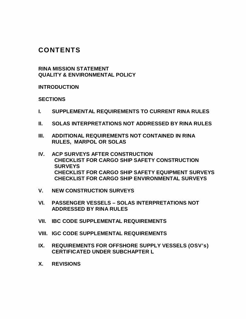
RINA MISSION STATEMENT QUALITY & ENVIRONMENTAL POLICY INTRODUCTION SECTIONS I. SUPPLEMENTAL REQUIREMENTS TO CURRENT RINA RULES II. SOLAS INTERPRETATIONS NOT ADDRESSED BY RINA RUL ES III. ADDITIONAL REQUIREMENTS NOT CONTAINED IN RINA
RULES, MARPOL OR SOLAS IV. ACP SURVEYS AFTER CONSTRUCTION
CHECKLIST FOR CARGO SHIP SAFETY CONSTRUCTION SURVEYS CHECKLIST FOR CARGO SHIP SAFETY EQUIPMENT SURVEYS CHECKLIST FOR CARGO SHIP ENVIRONMENTAL SURVEYS
V. NEW CONSTRUCTION SURVEYS VI. PASSENGER VESSELS – SOLAS INTERPRETATIONS NOT
ADDRESSED BY RINA RULES VII. IBC CODE SUPPLEMENTAL REQUIREMENTS VIII. IGC CODE SUPPLEMENTAL REQUIREMENTS IX. REQUIREMENTS FOR OFFSHORE SUPPLY VESSELS (OSV’s )
CERTIFICATED UNDER SUBCHAPTER L X. REVISIONS
Introduction-1
U. S. Supplement Sect ion I
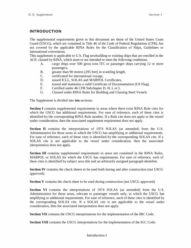
INTRODUCTION
The supplemental requirements given in this document are those of the United States Coast Guard (USCG), which are contained in Title 46 of the Code of Federal Regulations (CFR), but not covered by the applicable RINA Rules for the Classification of Ships, Guidelines or international conventions. This supplement is applicable to U.S. Flag newbuilding or existing ships that are enrolled in the ACP, classed by RINA, which meet or are intended to meet the following conditions:
A. cargo ships over 500 gross tons ITC or passenger ships carrying 12 or more passengers,
B. greater than 90 meters (295 feet) in scantling length, C. certificated for international voyage, D. issued ICLL, SOLAS and MARPOL Certificates, E. issued and maintains a valid Certificate of Documentation (US Flag), F. Certified under 46 CFR Subchapter D, H, I, or L G. Classed under RINA Rules for Building and Classing Steel Vessels
The Supplement is divided into ten sections: Section I contains supplemental requirements in areas where there exist RINA Rule cites for which the USCG has additional requirements. For ease of reference, each of these cites is identified by the corresponding RINA Rule number. If a Rule cite does not apply to the vessel under consideration, then the associated supplement requirement does not apply. Section II contains the interpretations of 1974 SOLAS (as amended) from the U.S. Administration for those areas in which the USCG has amplifying or additional requirements. For ease of reference, each of these cites is identified by the corresponding SOLAS cite. If a SOLAS cite is not applicable to the vessel under consideration, then the associated interpretation does not apply. Section III contains supplemental requirements in areas not contained in the RINA Rules, MARPOL or SOLAS for which the USCG has requirements. For ease of reference, each of these cites is identified by subject area title and an arbitrarily assigned paragraph identifier. Section IV contains the check sheets to be used both during and after construction (not USCG approved). Section V contains the check sheet to be used during construction (not USCG approved). Section VI contains the interpretations of 1974 SOLAS (as amended) from the U.S. Administration for those areas, relevant to passenger vessels only, in which the USCG has amplifying or additional requirements. For ease of reference, each of these cites is identified by the corresponding SOLAS cite. If a SOLAS cite is not applicable to the vessel under consideration, then the associated interpretation does not apply. Section VII contains the USCG interpretations for the implementation of the IBC Code. Section VIII contains the USCG interpretations for the implementation of the IGC Code.
Introduction-2
U. S. Supplement Sect ion I
Section IX contains the supplemental requirement for OSV’s > 90 Meters in Length. Section X Revisions
I-1
U. S. Supplement Sect ion I
I. SUPPLEMENTAL REQUIREMENTS TO CURRENT RINA RULES
Cite: Pt. A, Ch.1, Sec.1, 3.1.1 Duties of the Interest Parties – International and national regulations
Cargo Gear is to be certified in accordance with the “RINA Rules for Loading and Unloading Arrangements and for other Lifting Appliances on Board Ships, effective from 1 January 2009”, as applicable for the type of cargo gear being provided. As an alternative, evidence of approval issued by recognized bodies in accordance with requirements deemed equivalent by RINA to those contained in the above mentioned Rules may be submitted. The recognized bodies are only IACS Classification Societies.
Cite: Pt B, Ch 3 Intact Stability Intact stability for cargo and passenger vessels is to comply with the applicable parts of Subchapter S, except that (a) the weather criteria set out in 46 CFR 170.170 and 46 CFR 170.173 are to be complied
with in lieu of those contained under Pt A of the IS Code, (b) the passenger weight is to be considered as 83,9 Kg (185 pounds) in lieu of 75 kg (165
pounds). It has been determined that IMO Resolution MSC.267 (85), “International Code on Intact Stability, 2008” (2008 IS Code) is equivalent to the intact stability requirements of Subchapter S. Where the intact stability requirements contained in IMO Resolution MSC.267 (85) are used as specified above, the Regulations contained in Subparts B, Lifting, and E, Towing, of Subchapter S are also to be satisfied, where applicable. With the exception of weather criteria, and passengers weight, all recommendations that appear in the 2008 IS Code on Intact Stability are required and considered mandatory.
Cite: Pt B, Ch 3, App 1 Inclining Test Notwithstanding what stated in Pt B, Ch 3, App 1 Para 1.1.4 of the RINA Rules, three pendulums are recommended on all vessels. One or two of the pendulums may be substituted by inclinometers, water tubes, or other measuring device.
Cite:Pt F, Ch 13, Sec 11 Damage Stability Relative to damage stability, please note that all dry cargo vessels over 80 meters in length that change flag to US shall be considered to be new vessels for compliance with the probabilistic damage stability regulations in SOLAS, 1974, as amended, Chapter II-1, regardless of the actual build date.
Cite:Pt C, Ch 1, Sec 11, 3.4 Steering Gear – Control Systems The main steering gear is to be provided with full follow-up control in the pilothouse. Follow-up control means closed-loop (feedback) control that relates the position of the helm to a
I-2
U. S. Supplement Sect ion I
specific rudder angle by transmitting the helm-angle order to the power actuating system and, by means of feedback, automatically stopping the rudder when the angle selected by the helm is reached.
Cite: Pt C, Ch 1, Sec 11, 2.4 Steering Gear – Instrumentation and Alarms This requirement applies to each vessel of 1600 gross tons and over that has power driven main or auxiliary steering gear. The steering failure alarm system must be independent of each steering gear control system, except for the input received from the steering wheel shaft. The steering failure alarm system must have audible and visible alarms in the pilothouse when the actual position of the rudder differs by more than 5 degrees from the rudder position ordered by the follow-up control systems for more than: (a) 30 seconds for ordered rudder position changes of 70 degrees, (b) 6.5 seconds for ordered rudder position changes of 5 degrees, and (c) the time period calculated by the following formula for ordered rudder position changes
between 5 degrees and 70 degrees:
t = (R/2.76) + 4.64 Where: t = maximum time delay in seconds R = ordered rudder change in degrees
Each steering failure alarm system must be supplied by a circuit that is independent of other steering gear systems and steering alarm circuits.
Cite: Pt C, Ch 1, Sec 3 Boilers and Pressure Vessels and Heat Exchangers Boilers, pressure vessels and heat exchangers are to comply with the requirements of ASME Boiler and Pressure Vessel Code Section VIII, Division 1 or Division 2. Other standards such as Pt. C Ch. 1 Sec. 3 of RINA rules will be considered on a case by case base in coordination with the Marine Safety Center.
Cite: Pt C, Ch 1, Sec 10, 2.1 Piping Systems – Metallic Piping – Valves A valve in which the closure is accomplished by resilient nonmetallic material instead of a metal to metal seat shall comply with the design, material and construction specified below. Valves employing resilient material shall be divided into three categories; Positive shutoff, Category A and Category B and shall be tested and used as follows: (a) Positive Shutoff Valves – The closed valve must pass less than 10 ml/hr (0.34 fluid
oz/hr) of liquid or 3 liters/hr (0.11 ft 3/hr) of gas per inch nominal pipe size through the line after removal of all resilient material and testing at full rated pressure. Packing material must be fire resistant. Piping subject to internal head pressure from a tank containing oil (fuel, lube and cargo) must be fitted with a positive shutoff valve at the tank. See Pt. C Ch.1 Sec. 10 [11.6.4] of RINA Rules for additional requirements for such valves. Positive shutoff valves may also be used in any location in lieu of a required Category A or Category B valve.
(b) Category A Valves – The closed valve must pass less than the greater of 5% of its fully
I-3
U. S. Supplement Sect ion I
open flow rate or 15% / ( NPS ) of its fully open flow rate through the line after removal of all resilient material and testing at full rated pressure. Category A valves may be used in any piping system except where positive shutoff valves are required. Category A valves are required in the following locations:
• Valves at vital piping (Fuel, Fire Main, Bilge, Steering, Propulsion and its necessary auxiliaries, Ship’s Service and Emergency Electrical Generation) system manifolds;
• Isolation valves in cross-connects between two piping systems, at least one of which is a vital system, where failure of the valve in a fire would prevent the vital system(s) from functioning as designed;
• Valves providing closure for any opening in the shell of the vessel. (c) Category B Valves – The closed valve will not provide effective closure of the line or
will permit appreciable leakage from the valve after the resilient material is damaged or destroyed. Category B valves are not required to be tested and may be used in any location except where a Category A or Positive shutoff valve is required.
If a valve designer elects to use either calculations or actual fire testing in lieu of material removal and pressure testing, the proposed calculation method or test plan must be accepted by the Commandant. The use of heat sensitive materials is prohibited in piping systems conveying flammable or combustible products. Heat sensitive materials are those having a solidus melting point below 927˚C (1700˚F). This may preclude the use of bronze piping components
Cite: Pt C, Ch 1, Sec 10, 2.1.3 Piping Systems – Plastic Piping Pipes and piping components made of thermoplastic or thermosetting plastic materials, with or without reinforcement, are to conform to IMO Res. A.753(18). Piping required to meet flame, fire endurance, and/or smoke generation/toxicity requirements of A.753(18) must be USCG type approved. Plastic pipe is not permitted in a concealed space in an accommodation or service area unless the smoke generation and toxicity requirements of IMO Res. A.753(18) are met.
Cite: Pt C, Ch 1, Sec 10, 2.7 Valves and accessories Reference is to be made to 46 CFR 56-20 and 46 CFR 57. Valve bypasses shall be in accordance with MSS SP-45 and should be at least scheduled 80 seamless dependant on the properties of the main line piping. Lesser thicknesses may be approved depending on service. 46 CFR 56.20-20 Power actuated valves in systems other than those on systems containing oil may be used if approved for the system by the Marine Safety Center. All power actuated valves required in an emergency to operate the vessel’s machinery, to maintain its stability, and to operate the bilge and firemain systems must have a manual means of operation. Remote valve controls that are not readily identifiable as to service must be fitted with nameplates.
I-4
U. S. Supplement Sect ion I
Remote valve controls must be accessible under service conditions. Remote valve controls, except reach rods, must be fitted with indicators that show whether the valves they control are open or closed. Valve position indicating systems must be independent of valve control systems. Valve reach rods must be adequately protected. Solid reach rods must be used in tanks containing liquids, except that tank barges having plug cocks inside cargo tanks may have reach rods of extra-heavy pipe with the annular space between the lubricant tube and the pipe wall sealed with a nonsoluble to prevent penetration of the cargo. Air operated remote control valves must be provided with self-indicating lines at the control boards which indicate the desired valve positions, i.e., open or closed.
Suitable drains shall be provided at low points of piping systems.
Valves and cocks shall be located so as to be easily accessible and valves or cocks attached to the shell of the vessel or to sea chests located below the floorplating shall be operable from above the floorplates.
When welded fabrication is employed, a sufficient number of detachable joints shall be provided to facilitate overhauling and maintenance of machinery and appurtenances. The joints shall be located so that adequate space is provided for welding, and the location of the welds shall be indicated on the plans.
Piping, including valves, pipe fittings and flanges, conveying vapors, gases or liquids whose temperature exceeds 65,5°C (150 °F), shall be suitably insulated where necessary to preclude injury to personnel.
Where pipes are run through dry cargo spaces they must be protected from mechanical injury by a suitable enclosure or other means.
Cite: Pt C, Ch 1, Sec 10, 2.8 Sea inlet and overboard discharge A.1 All inlets and discharges led through the vessel’s side shall be fitted with efficient and
accessible means, located as close to the hull penetrations as is practicable, for preventing the accidental admission of water into the vessel either through such pipes or in the event of fracture of such pipes.
A.2 The number of scuppers, sanitary discharges, tank overflows, and other similar openings in the vessel’s side shall be reduced to a minimum, either by making each discharge serve for as many as possible of the sanitary and other pipes, or in any other satisfactory manner.
A.3 In general, when the bulkhead deck is above the freeboard deck, the requirements of this
I-5
U. S. Supplement Sect ion I
section apply relative to the bulkhead deck. For vessels not assigned load lines, such as certain inland vessels and barges, the weather deck shall be taken as the freeboard deck.
B.1 Scuppers and discharge pipes originating at any level and penetrating the shell either more than 171⁄2 inches (450mm) below the freeboard deck or less than 231⁄2 inches (600mm) above the summer load waterline must be provided with an automatic nonreturn valve at the shell. This valve, unless required by paragraph (b)(2) of this section, may be omitted if the piping is not less than Schedule 80 in wall thickness for nominal pipe sizes through 8 inches, Schedule 60 for nominal pipe sizes above 8 inches and below 16 inches, and Schedule 40 for nominal pipe sizes 16 inches and above.
B.2 Discharges led through the shell originating either from spaces below the freeboard deck or from within enclosed superstructures and equivalent deckhouses on the freeboard deck shall be fitted with efficient and accessible means for preventing water from passing inboard. Normally each separate discharge shall have one automatic nonreturn valve with a positive means of closing it from a position above the freeboard deck. Where, however, the vertical upward distance from the summer load line to the inboard end of the discharge pipe through which flooding can take place exceed 0.01L, the discharge may have two automatic nonreturn valves without positive means of closing, provided that the inboard valve is always accessible for examination under service conditions. Where that vertical distance exceeds 0.02L a single automatic nonreturn valve without positive means of closing is acceptable. In an installation where the two automatic nonreturn valves are used, the inboard valve must be above the tropical load line. The means for operating the positive action valve shall be readily accessible and provided with an indicator showing whether the valve is open or closed. A suitable arrangement shall be made to insure the valve is not closed by unauthorized persons, and a notice shall be posted in a conspicuous place at the operating station to the effect that the valve shall not be closed except as required in an emergency.
B.3 Where scuppers and drains are installed in superstructures or deckhouses not enclosed they shall be led overboard. Refer to paragraph B.1 for any nonreturn valve requirement.
B.4 Sanitary pump discharges leading directly overboard or via a holding tank must meet the standards prescribed by this paragraph. The location of the sanitary system openings within the vessel determines whether the requirements of paragraph B.2 or B.3 are applicable.
C. Overflow pipes which discharge through the vessel’s side must be located as far above the deepest load line as practicable and fitted with valves as required by paragraph B Two automatic nonreturn valves must be used unless it is impracticable to locate the inboard valve in an accessible position, in which case a nonreturn valve with a positive means of closure from a position above the freeboard deck will be acceptable. Overflows which extend at least 30 inches above the freeboard deck before discharging overboard may be fitted with a single automatic nonreturn valve at the vessel’s side. Overflow pipes which serve as tank vents must not be fitted with positive means of closure without the specific approval of the Marine Safety Center. Overflow pipes may be vented to the weather.

I-6
U. S. Supplement Sect ion I
D.1 Sea inlets and discharges, such as used in closed systems required for the operation of main and auxiliary machinery, as in pump connections or scoop injection heat exchanger connections, need not meet the requirements of paragraphs B.1 and B.2 but instead shall be fitted with a shutoff valve located as near the shell plating as practicable, and may be locally controlled if the valve is located in a manned machinery space. These controls shall be readily accessible above the floor plates and shall be provided with indication showing whether the valve is opened or closed. Manned machinery spaces include the main machinery space and are either attended by the crew or are automated in accordance with part 62 of this subchapter to be comparable to an attended space.
D.2 In unmanned machinery spaces, all machinery inlets and discharges as described in paragraph D.1 shall be remotely operable from a position above the freeboard deck unless otherwise approved and shall meet the access and marking requirements of paragraph B.2 .
E.1 Pipes terminating at the shell plating shall be fitted with bends or elbows between the outboard openings and the first rigid connection inboard. In no case shall such pipes be fitted in a direct line between the shell opening and the first inboard connection.
E.2 Seachests and other hull fittings shall be of substantial construction and as short as possible. They shall be located as to minimize the possibility of being blocked or obstructed.
E.3 The thickness of inlet and discharge connections outboard of the shutoff valves, and exclusive of seachests, must be not less than that of Schedule 80 for nominal pipe sizes through 8 inches, Schedule 60 for nominal pipe sizes above 8 inches and below 16 inches, and Schedule 40 for nominal pipe sizes 16 inches and above.
F. Valves required by this section and piping system components outboard of such required valves on new vessel installations or replacements in vessels of 150 gross tons and over shall be of a steel, bronze, or ductile cast iron specification listed in 46 CFR 56.60-1 Table 56.60– 1(A). Lead or other heat sensitive materials having a melting point of 926°C (1,700 °F). or less shall not be used in such service, or in any other application where the deterioration of the piping system in the event of fire would give rise to danger of flooding. Brittle materials such as cast iron shall not be used in such service. Where nonmetallic materials are used in a piping system, and shell closures are required by this section, a positive closure metallic valve is required
G. The inboard openings of ash and rubbish-chute discharges shall be fitted with efficient covers. If the inboard opening is located below the freeboard deck, the cover shall be watertight, and in addition, an automatic nonreturn valve shall be fitted in the chute in any easily accessible position above the deepest load line. Means shall be provided for securing both the cover and the valve when the chute is not in use. When ash-ejectors or similar expelling devices located in the boilerroom have the inboard openings below the deepest load line, they shall be fitted with efficient means for preventing the accidental admission of water. The thickness of pipe for ash ejector discharge shall be not less than Schedule 80.
I-7
U. S. Supplement Sect ion I
H. Where deck drains, soil lines, and sanitary drains discharge through the shell in way of cargo tanks on tank vessels, the valves required by this section shall be located outside the cargo tanks. These valves shall meet the material requirements of paragraph F. The piping led through such tanks shall be fitted with expansion bends where required, and shall be of steel pipe having a wall thickness of not less than five-eighths inch, except that the use of suitable corrosion-resistant material of lesser thickness will be given special consideration by the Commandant. All pipe joints within the tanks shall be welded. Soil lines and sanitary drains which pass through cargo tanks shall be provided with nonreturn valves with positive means of closing or other suitable means for preventing the entrance of gases into living quarters.
I. Except as provided for refrigerating plant relief valve gas discharge led through the side of the vessel below the freeboard deck, sea valves must not be held open with locks. Where it is necessary to hold a discharge or intake closed with a lock, either a locking valve may be located inboard of the sea valve, or the design must be such that there is sufficient freedom of motion to fully close the locked sea valve after an event, such as fire damage to the seat, causes significant leakage through the valve. Valves which must be opened in and emergency, such as bilge discharges or fire pump suctions must not be locked closed, whether they are sea valves or not.
Cite: NAS.10 Fire Safety Systems – Fire-Extinguishing Systems and Equipment – Fire Mains
Where differences exist between NAS.10 and 46 CFR Part 95.10, the more conservative requirement shall be applied.
Cite: Pt C, Ch. 2, Supply systems and characteristics of the supply Sec. 3, 1.1.3
The hull return system of distribution is not to be used for power, heating or lighting in any ship.
Cite: Pt C, Ch. 2, Sources of electrical power Sec. 3, 2.2.11
If transformers are used to supply the ship’s service distribution system for ships and mobile offshore drilling units, there must be at least two installed, independent power transformers. With the largest transformer out of service, the capacity of the remaining units must be sufficient to supply the ship service loads. Where a bank of single-phase transformers are provided to supply the ship’s service distribution system e.g. three-phase loads such as fire pumps or steering gear, a back-up bank of single-phase transformers shall be provided to provide the same redundancy as two three-phase transformers.
Cite:Pt C, Ch. 2, General requirements for distribution systems Sec. 3, 3.4 Time for starting and connection to the main switchboard must be both not more than 30 seconds and less than the time to start and connect the emergency generator to the emergency
I-8
U. S. Supplement Sect ion I
switchboard.
Cite: Pt C, Ch. 2, Emergency Source of Electrical Power Sec. 3, 2.3.12 A stop control for an emergency generator must only be in the space that has the emergency generator, except a remote mechanical reach rod is permitted for the fuel oil shutoff valve to an independent fuel oil tank located in the space.
Cite: Pt C, Ch. 2, Use of emergency generator in port & Emergency Sec. 3, 2.4 and 3.6 distribution of electrical power Each bus-tie between a main switchboard and an emergency switchboard must be arranged to prevent parallel operation of the emergency power source with any other source of electric power, except for interlock systems for momentary transfer of loads. Where the system is arranged for the emergency generator to backfeed the main switchboard the interconnecting feeder is to be protected at the emergency switchboard with overcurrent protection as well as short circuit protection If there is a reduction of potential of the normal source by 15 to 40 percent, the final emergency power source must start automatically without load. When the potential of the final emergency source reaches 85 to 95 percent of normal value, the emergency loads must transfer automatically to the final emergency power source. When the potential from the normal source has been restored, the emergency loads must be manually or automatically transferred to the normal source, and the final emergency power source must be manually or automatically stopped. The emergency generator may not be used during lat time in port if the emergency generator maintenance service intervals may be exceeded. Emergency power is to be provided for a period of 18 hours for one of the bilge pumps, when required by USCG 46 CFR 56, if dependent on the emergency generator for its source of power. Emergency lighting is to be provided, for a period of 18 hours, to allow safe operation of each power-operated watertight door.
Cite: Pt C, Ch. 2, Short circuit currents Sec. 3, 7 .2
For electrical systems of 1500kW aggregate generating capacity and above, the short circuit calculation method of 7.2.2 is mandatory. For electrical systems of less than 1500kW aggregate generating or source capacity the short circuit calculation method of 7.2.3 is acceptable. For direct current electrical systems of less than 1500kW aggregate generating capacity the short circuit calculation method of 46 CFR 111.52-3(a) may be used.
I-9
U. S. Supplement Sect ion I
Cite: Pt C, Ch. 1, Operation in inclined positions Sec. 1, 2.4
The emergency generator and its prime mover and any emergency accumulator battery shall be so designed and arranged as to ensure that they will function at full rated power when the ship is upright and when inclined at any angle of list up to 22.5° or when inclined up to 10° either in the fore or aft direction, or is in any combination of angles within those limits or inclined to the maximum angle of heel that results from the assumed damage defined in 33 CFR 155 or in subchapter S for the specific vessel type."
Cite:Pt C, Ch. 1, Alarms and safeguards for emergency diesel engines Sec. 2, 2.7.8 Three means of shutdowns are required: low L.O. Pressure, Overspeed and upon release of the Fixed Fire-Extinguishing System in the Emergency generator room.
Cite: Pt C, Ch. 2, Current carrying capacity of cables Sec. 3, 9.9 MCC and Lighting cables are not permitted a decrease in size if interlocks are employed.
Cite: Pt C, Ch. 2, Navigation lights Sec. 3, 3.13 Each navigation light must meet the following:
(a) Meet the technical details of the applicable navigation rules.
(b) Be certified by an independent laboratory to the requirements of UL 1104 or an equivalent standard.
(c) Be labeled with a label stating the following: “MEETS _______________________ ” (Insert the identification name or number of the standard under paragraph (b) above to which the light was tested.) “TESTED BY ___________________ ” (Insert the name or registered certification mark of the independent laboratory that tested the fixture to the standard under paragraph (b) above.) Manufacturer’s name. Model number. Visibility of the light in nautical miles. Date on which the fixture was Type Tested. Identification of the bulb used in the compliance test.
Cite: Pt C, Ch. 2, Transformers Sec. 5, 1.4 For type A insulation class the temperature rise limit is 50°C (122 °F) considering an amb. Temperature of 45°C (113°F) ,or 55°C (131°F) considering an amb. Temperature of 40°C (104°F)
I-10
U. S. Supplement Sect ion I
Cite: Pt C, Ch. 2, Valve regulated sealed battery Sec. 7, 1.3 Where valve-regulated sealed batteries are used in lieu of vented batteries, calculations must be submitted to justify lesser ventilation than required for vented batteries of the same capacity.
Cite: Pt C, Ch. 4, Sec. 1 Fixed gas fire extinguishing systems and NAS 10 Alarms shall be pneumatically powered by the extinguishing agent or inert gas per USCG Type Approval. Electrically powered alarms are prohibited.
Cite: Pt F, Ch. 3, Communication system Sec. 1, 1.3 The voice communication system power supply must ensure sufficient redundancy and capacity to be considered able to operate independent of the vessel's electrical system in which the loss of any one system component will not disable the rest of the system.
Cite: Pt C, Ch. 1, Communication Sec. 1, 3.8 On a vessel with more than one propulsion engine, each engine must have an engine order telegraph. On a double-ended vessel that has two navigating bridges, this system must be between the engine room and each navigating bridge. On vessels equipped with pilothouse control, each local control station in the engine room must have an indicator if the local control station is not immediately adjacent to the engine room control station and if the local control station does not have reliable voice communications, and if the local control station can be used to control propulsion. Engine order telegraph and remote propulsion control systems must be electrically separate and independent, except that a single mechanical operator control device with separate transmitters and connections for each system may be used. Each vessel with navigating bridge throttle control must have a positive mechanical stop on each telegraph transmitter that prevents movement to the “Navigating Bridge Control” position without positive action by the operator. Electric Engine Order Telegraph System
Where two or more transmitters, located on or on top of, or on the wings of, the navigating bridge operate a common indicator in the engine room, all transmitter
I-11
U. S. Supplement Sect ion I
handles and pointers must operate in synchronism or operate under the control of a transmitter transfer control as described below. Where the transmitters are mechanically interlocked to effect synchronous operation, a failure of a wire or chain at any transmitter must not interrupt or disable any other transmitter. Transmitter Transfer Control System: Except for a transmitter in an unattended navigating bridge on a double-ended vessel, each transmitter must operate under the control of a transmitter transfer control so that movement of any one transmitter handle automatically connects that transmitter electrically to the engine room indicator and simultaneously disconnects electrically all other transmitters. The reply pointers of all transmitters must operate in synchronism at all times. On a double-ended vessel that has two navigating bridges, a manually operated transfer switch which will disconnect the system in the unattended navigating bridge must be provided. Each electric engine order telegraph system must have transmitters and indicators that are electrically connected to each other. Each engine room indicator must be capable of acknowledgment of orders. Each system must have an alarm on the navigating bridge that automatically sounds and visually signals a loss of power to the system. The alarm is to be provided with means to reduce the audible signal from 100 percent to not less than 50 percent. Mechanical Engine Order Telegraph System
Each mechanical engine order telegraph system must consist of transmitters and indicators mechanically connected to each other. Each transmitter and each indicator must have an audible signal device to indicate, in the case of an indicator, the receipt of an order, and in the case of a transmitter, the acknowledgment of an order. The audible signal device must not be dependent upon any source of power for operation other than that of the movement of the transmitter or indicator handle. If more than one transmitter operates a common indicator in the engine room, all transmitters much be mechanically interlocked and operate in synchronism. Where the transmitters are mechanically interlocked to effect synchronous operation, a failure of a wire or chain at any transmitter must not interrupt or disable any other transmitter. A sound-powered telephone system or other reliable voice communication method must be installed that is independent of the vessel's electrical system (Ref: 46 CFR 113.30-3(b)).
Cite: Pt C, Ch. 1, Steering gear – circuit protection Sec. 11, 2.3.5 AC Steering Gear motors. The steering gear feeder must be provided with instantaneous trip protection (no overload protection allowed)
I-12
U. S. Supplement Sect ion I
Cite: Pt C, Ch. 2, Sec. 8 Switchgear and control gear assembly Each AC switchboard must have a voltage regulator functional cut-out switch for transferring from automatic to manual control mode and a manual control rheostat for exciter field. This is not applicable if the exited current for the emergency generator is provided by attached rotating exciters of by static exciters deriving their source of power from the machines controlled. Exceptions:
(a) Where the electric plant has generators in excess of the number required by the rules such that the main source of electrical power requirements of Pt. C Ch. 2 Sec. 3 [2.2] can be met with two generators unavailable, no manual control rheostat for the exciter field is required.
(b) Where the generators required by Pt. C Ch. 2 Sec. 3 [2.2] are each provided with a permanently wired back-up automatic voltage regulator which can be immediately brought into service, no manual control rheostat for the exciter field is required.
Cite: Pt C, Ch. 2, A.c. generators Sec. 4, 2.2 A static exciter is prohibited by 46 CFR 111.12-3 for the emergency generator, unless the generator is provided with a permanent magnet or residual magnetism type exciter that has the capability of voltage build-up after two month of no operation.
Cite:Pt C, Ch. 2, Electrical installation in hazardous areas Sec. 3, 10.2 Electrical Cables For electric cables in hazardous areas, the electric cable construction and the cable glands are to achieve the appropriate seal so that gas cannot migrate or pass through the cable. IEC 60092-3, IEC 60092-350 and IEC 60092-353 are acceptable cable constructions standards to be used.
Cite: Pt C, Ch. 2, Electrical installation in hazardous areas Sec. 3, 10.1 Electrical Equipment IEC certificated safe equipment must be tested or approved under the IECEx scheme and certification body must be recognized by the Commandant (i.e., certification under the ATEX scheme is not acceptable). See Section II/Cite: II-1/45. Intrinsically safe systems or associated apparatus must meet the following “Ex ia” for Zones 0 and 1 (Class I, Division 1); and “Ex ib” for Zone 2 (Class I, Division 2).
Pt C Ch. 2, Sec. 12, 7 Installation - Cables
Painting of cables is not permitted.
I-13
U. S. Supplement Sect ion I
Pt F Ch. 3, Sec. 1, 2 AUT-UMS - Documentation Pt C Ch. 3, Sec. 3, 5.2.3 Failure analysis for safety related functions The degree of remote propulsion control and automation is to be based on the level of manning intended for the propulsion machinery space. Where it is intended to obtain USCG certification for a minimally attended machinery space, the RINA requirements for AUT-CCS as well as the additional Cites contained in this Supplement are applicable. Where it is intended to obtain USCG certification for an unattended machinery space, the RINA requirements for AUT-UMS as well as the additional Cites contained in this Supplement are applicable. Note: It is the Owner’s responsibility to advise RINA as to the level of manning of the propulsion machinery space that will requested from the USCG. One copy of a qualitative failure analysis must be submitted for propulsion controls, microprocessor-based system hardware, safety controls, automated electric power management, automation required to be independent that is not physically separate and any other automation that in the judgment of the reviewing authority potentially constitutes a safety hazard to the vessel or personnel in case of failure. The QFA should enable the designer to eliminate single points of failure. Note: The qualitative failure analysis is intended to assist in evaluating the safety and reliability of the design. It should be conducted to a level of detail necessary to demonstrate compliance with applicable requirements and should follow standard qualitative analysis procedures. Assumptions, operating conditions considered, failures considered, cause and effect relationships, how failures are detected by the crew, alternatives available to the crew, and necessary design verification tests should be included. Questions regarding failure analysis should be referred to the reviewing authority at an early stage of design. A Design Verification test is to be performed once, immediately after the installation of the automated equipment or before issuance of the initial Certificate of Inspection (and thereafter whenever major changes are made to the system or its software), to verify that automated systems are designed, constructed and operate in accordance with the applicable RINA rules and requirements of this supplement. The purpose of design verification testing is to verify the conclusions of the QFA. The Design Verification Test Procedure (DVTP) is therefore an extension of the QFA and the two may be combined into one document. The DVTP should demonstrate that all system failures are alarmed and that all switchovers from a primary system component to a back-up component are also alarmed. Periodic Safety tests must be conducted annually to demonstrate the proper operation of the primary and alternate controls, alarms, power sources, transfer override arrangements, interlocks and safety controls. Systems addressed must include fire detection and extinguishing, flooding safety, propulsion, maneuvering, electric power generation and distribution and emergency internal communications. Table in Pt F Ch. 3 of RINA rules as applicable to the vessel’s installed machinery and level of manning, should be used as a guide in developing the Periodic Safety Test Procedure (PSTP). Design Verification and Periodic Safety test procedures are to be submitted for approval and retained aboard the vessel. Test procedure documents must be in a step-by-step or check off list format. Each test instruction must specify equipment status, apparatus necessary to perform the tests, safety precautions, safety control and alarm set points, the procedure to the followed, and the expected test result. Test techniques must not simulate monitored system conditions by maladjustment, artificial signals, improper wiring, tampering, or revision of the system unless the test would damage equipment or endanger personnel. Where a test meeting the restrictions on test techniques will damage equipment or
I-14
U. S. Supplement Sect ion I
endanger personnel, an alternative test method shall be proposed together with an explanation of why it is an equivalent test. It is important to remember that the DVTP tests the response of the automation system to component failures within the system as predicted by the QFA and that the PSTP tests the performance of the automation system, its sensors, alarms, and actuators, and the interconnecting wiring. The design verification and periodic safety tests are to be witnessed by the surveyor. The USGC Officer in Charge Marine Inspection must be notified prior to testing and may choose to attend these tests to verify that vital system automation is appropriate to the level of manning requested on the vessel’s Certificate of Inspection. Vessels with minimally attended or periodically unattended machinery plants must have a planned maintenance program to ensure continued safe operation of all vital systems. The program must include maintenance and repair manuals for work to be accomplished by maintenance personnel and check off lists for routine inspection and maintenance procedures. The planned maintenance program must be functioning prior to the completion of the evaluation period for reduced manning. Maintenance and repair manuals must include details as to what, when and how to troubleshoot, repair and test the installed equipment and what parts are necessary to accomplish the procedures. Schematic and logic diagrams must be included in this documentation. Manuals must clearly delineate information that is not applicable to the installed equipment.
Cite: Pt C, Ch. 3, Sec. 2, 7 Safety system Safety systems must not operate as a result of failure of the normal electric power source unless it is determined to be the failsafe state. Sensors for the primary speed, pitch or direction of rotation control in closed loop propulsion control systems must be independent and physically separate from required safety, alarm or instrumentation sensors.
Cite: Pt C, Ch. 1, Starting arrangements Sec. 2, 3.1 An alarm to indicate starting capability of less than 50 percent of the requirement total starting capacity must be provided.
Cite: Pt C, Ch. 3, Sec. 2, 4 Control of Propulsion Machinery Propulsion control from the Navigating Bridge is to be provided.
Cite: Pt C, Ch. 4, Sec. 1 Requirements for Fire Protection, Detection and Extinction
Fixed fire suppression systems must be USCG Type Approved equipment. Design and installation shall be in accordance with the USCG Type approved manual.
Cite: Pt F, Ch. 3, Alarm System Design Sec. 1, 5.2
I-15
U. S. Supplement Sect ion I
A personnel alarm must be provided and must annunciate on the Navigating Bridge if not routinely acknowledged at the centralized control station or in the machinery space. All required alarms must annunciate throughout the Centralized Control Station and the machinery space.
Cite: Pt F, Ch. 3, Control of electrical installation Sec. 1, 4.8.3 The standby electric power is to be available in no more than 30 seconds.
Cite: Pt F, Ch. 3, Sec. 1, 3.1 Fire prevention The fire detection and alarm system of approved type must activate all alarms at the Centralized Control Station, the Navigating Bridge, and throughout the machinery spaces and engineer’s accommodations.
Cite: Pt E, Ch 7, Sec 4, 4.2 Specific Vessel Types – Vessels Intended to carry Oil in Bulk – Pressure Vacuum Valves and High Velocity Vent Valves
Pressure vacuum relief valves and high velocity vent valves installed on tank vessels must be USCG approved equipment.
Cite: Pt E, Ch 7, Sec 4, 3 Specific Vessel Types – Vessels Intended to Carry Oil in Bulk – Cargo Oil System
The provisions in Pt E Ch 7 Sec 4 [3.4.1] of the Rules, which permit the unrestricted routing of cargo piping through ballast tanks for vessels less than 5000 tons deadweight, is not acceptable on U.S. flagged vessels. The requirements of Pt C Ch 1 Sec 10 [11.6.4] of the Rules for positive closing valves to be fitted on pipes emanating from fuel oil tanks which are subject to a static head of oil are also applicable to pipes from cargo oil tanks which are subject to a static head of oil.
Cite: Pt E, Ch 7, Sec 4, 2.3 Specific Vessel Types – Vessels Intended to Carry Oil in Bulk – Ballast System
The provisions in Pt E Ch 7 Sec 4 [2.3.7] of the Rules, which permit the unrestricted routing of ballast piping through cargo tanks for vessels less than 5000 tons deadweight, is not acceptable on U.S. flagged vessels.
I-16
U. S. Supplement Sect ion I
Cite: Pt E, Ch 7, Sec 4, 2.6 Specific Vessel Types – Vessels Intended to Carry Oil in Bulk – Cargo Heating Systems
A thermal fluid heater must be fitted with a control which prevents the heat transfer fluid from being heated above its flash point. Reference is to be made to 46 CFR 61.30, in particular, the following checks of a thermal fluid heater must be performed in the presence of a USCG Marine Inspector: pre-purge, ignition sequence, combustion control, flame safeguards, limit controls (low fluid output, low flow cutout, high temperature cutout) and post-purge.
Cite: Pt F, Ch 13, Sec 7 Specific Vessel Types – Vessels Intended to Carry Oil in Bulk – Cargo Vapor Emission Control Systems
In addition to meeting the requirements in Pt F Ch 13 Sec 7 of the Rules, for the additional class notation VAPOUR CONTROL SYSTEM (VCS): (a) Personnel training should be verified. (b) Markings for overfill protection outside the control room should be in 50 mm (2 in) high
black letters on a white background. (c) Each cargo tank shall have arrangements that allow oxygen measurements to be taken at
a point 1 m (3.3 ft) below the tank top and from a point at half the ullage prior to cargo transfer when cargo vapor is collected by a facility that requires the vapor from the vessel to be inerted, or when cargo vapor is transferred between vessels during lightering or topping off operations with vapor balancing.
(d) In the case of Barges, an intrinsically safe overfill control system which actuates an
alarm and automatic shutdown system at the facility overfill control panel, or on the vessel to be lightered if a lightering operation, 60 seconds before the tank becomes 100 percent liquid full is to be provided
Cite: Pt E, Ch 7 Specific Vessel Types – Vessels Intended to Carry Oil in Bulk
Cite: Pt E, Ch 7, Sec 5 Specific Vessel Types – Vessels Intended to Carry Oil in Bulk – Electrical Installations
Cite: Pt E, Ch 9 Specific Vessel Types – Vessels Intended to Carry Liquefied Gases in Bulk
Cite: Pt E, Ch 8 Specific Vessel Types – Vessels Intended to Carry Chemicals in Bulk
Cite: Pt E, Ch 1 Specific Vessel Types – Vessels Intended to Carry Vehicles
Cite: Pt E, Ch 9, Sec 1, 1.1.1 Vessels Intended to Carry Liquefied Gases in Bulk and Vessels and Pt E Ch 8 Sec 1 [1.1.1] Vessels Intended to Carry Chemicals in Bulk – General
I-17
U. S. Supplement Sect ion I
Refer to Sections VII and VIII for Interpretations and Guidance for IBC and IGC Code Authorization on behalf of the USCG for the issuance of an International Certificate of Fitness.
Cite: Pt E, Ch 9, Sec 5, 1.1.1 Specific Vessel Types – Vessels Intended to Carry Liquefied Gases in Bulk – Process Pressure Vessels and Liquid, Vapor, and Pressure Piping Systems
Cargo containment systems and piping systems carrying nitrogen, other than for deck tanks and their piping systems, must be USCG approved equipment. Safety relief valves for liquefied compressed gas service must be USCG approved equipment. Reference is to be made to the complete 46 CFR 56
Cite: Pt E, Ch 9, Sec 19, 1.1 Specific Vessel Types – Vessels Intended to Carry Liquefied Gases in Bulk – Summary of Minimum Requirements – Explanatory Notes to the Summary of Minimum Requirements
A liquefied gas not included in the tables in Ch 19 of IGC Code and Pt E Ch 9 Sec 19 of RINA Rules must have USCG approval in order to be carried in bulk in U.S. waters.
II-1
U. S. Supplement Sect ion II
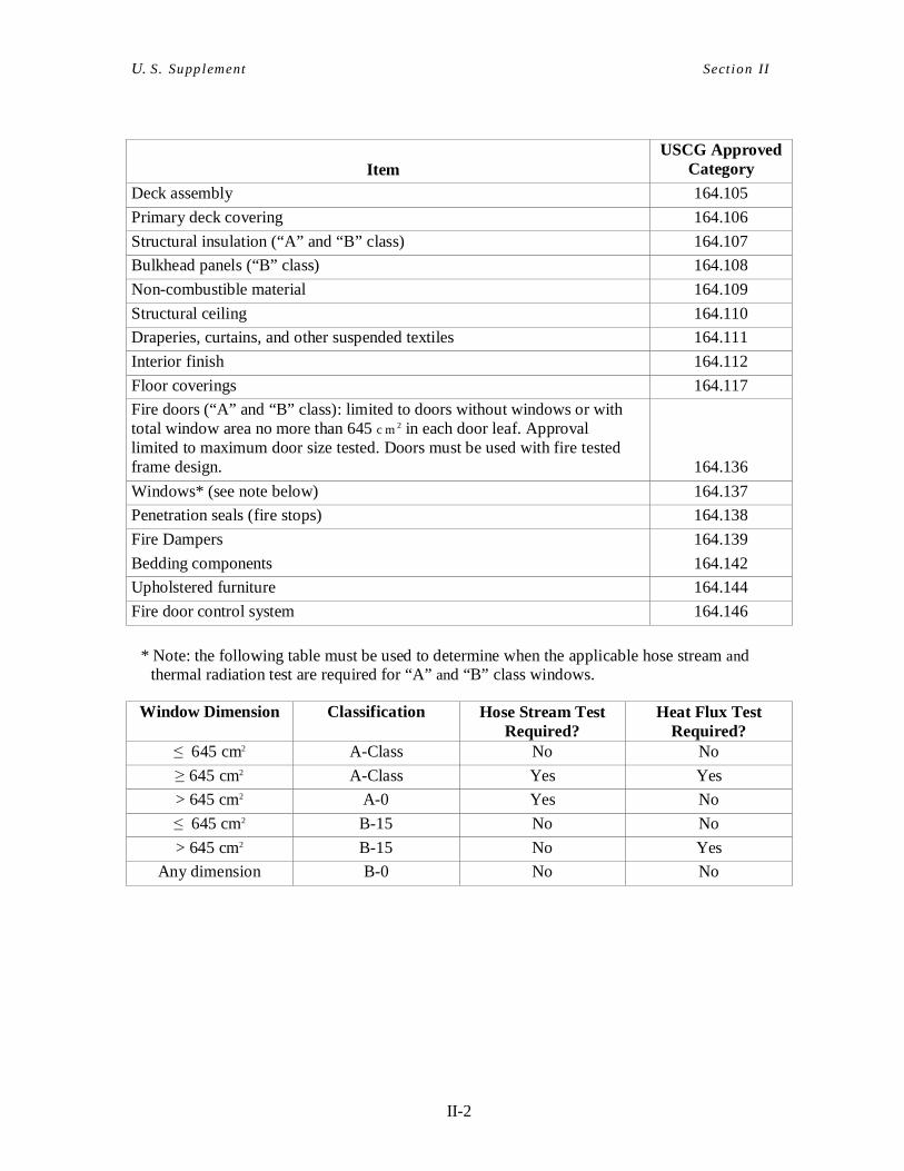
II. SOLAS INTERPRETATIONS NOT ADDRESSED BY RINA RU LES General Equipment Approvals Approvals of safety equipment, materials and installations are covered by regulations contained in 46 CFR 2.75. For U.S. flag vessels, specific and type approvals for fire suppression equipment, structural fire protection materials and life-saving appliances are performed by the USCG as mandated by SOLAS 1974, generally through independent laboratory testing and inspection. Provisions within the 1996 USCG Authorization Act also allow the use of equipment approved by or on behalf of other governments under certain circumstances. In the case of lifesaving appliances, there must be a reciprocal agreement in place before equipment approved by that country could be used on a U.S. vessel. ACP does not change the requirements to use USCG approved materials and equipment. Therefore, class society approvals cannot be used to fulfill the obligations of the USCG, as an Administration, where type approval is required by the regulations. The USCG approves applicable “SOLAS” lifesaving equipment using the IMO LSA Code. For fire protection items, the USCG approves “SOLAS” materials using the IMO Fire Test Procedures Code and the IMO Fire Safety Systems Code. Mutual Recognition Agreement (MRA) exists between the U.S. and the European Community (EC), and the U.S. and the European Free Trade Association (EFTA), which address a limited number of items of fire protection, lifesaving, and navigation equipment. The MRA makes it possible for a manufacturer with a European Approval (MED/wheelmark) to obtain USCG approval for certain equipment covered by the MRA. This is accomplished by permitting the “Notified Bodies” responsible for issuing approvals in Europe to issue USCG approval. Likewise, the USCG is able to issue the European Approval (MED/wheelmark) for manufacturers having a USCG approval if the item is included within the scope of the MRA. It is important to note that this MRA does not change the requirement of using USCG approved equipment and materials on U.S. Flag vessels. It allows an alternative means for obtaining USCG approval. The European Marine Equipment Directive (MED) “wheelmark” is not accepted in lieu of USCG approval. Further guidance is contained in NVIC 8-04 and NVIC 8-04 Change 1. Fire Equipment and Arrangements USCG type-approved materials and equipment from both U.S. and foreign sources approved in accordance with the procedures contained in 46 CFR 159 will continue to be acceptable, and those items manufactured in a country with which the United States has a Mutual Recognition Agreement in force or the USCG has found to have an equivalent approval program will also be acceptab le. As discussed above, the following structural fire protection materials approved by the MRA may be used in lieu of USCG type approved materials for ACP vessels.
II-2
U. S. Supplement Sect ion II
Item USCG Approved
Category
Deck assembly 164.105
Primary deck covering 164.106
Structural insulation (“A” and “B” class) 164.107
Bulkhead panels (“B” class) 164.108
Non-combustible material 164.109
Structural ceiling 164.110
Draperies, curtains, and other suspended textiles 164.111
Interior finish 164.112
Floor coverings 164.117
Fire doors (“A” and “B” class): limited to doors without windows or with total window area no more than 645 c m2 in each door leaf. Approval limited to maximum door size tested. Doors must be used with fire tested frame design. 164.136
Windows* (see note below) 164.137
Penetration seals (fire stops) 164.138
Fire Dampers 164.139
Bedding components 164.142
Upholstered furniture 164.144
Fire door control system 164.146
* Note: the following table must be used to determine when the applicable hose stream and thermal radiation test are required for “A” and “B” class windows.
Window Dimension Classification Hose Stream Test Required?
Heat Flux Test Required?
≤ 645 cm2 A-Class No No
≥ 645 cm2 A-Class Yes Yes
> 645 cm2 A-0 Yes No
≤ 645 cm2 B-15 No No
> 645 cm2 B-15 No Yes
Any dimension B-0 No No
II-3
U. S. Supplement Sect ion II
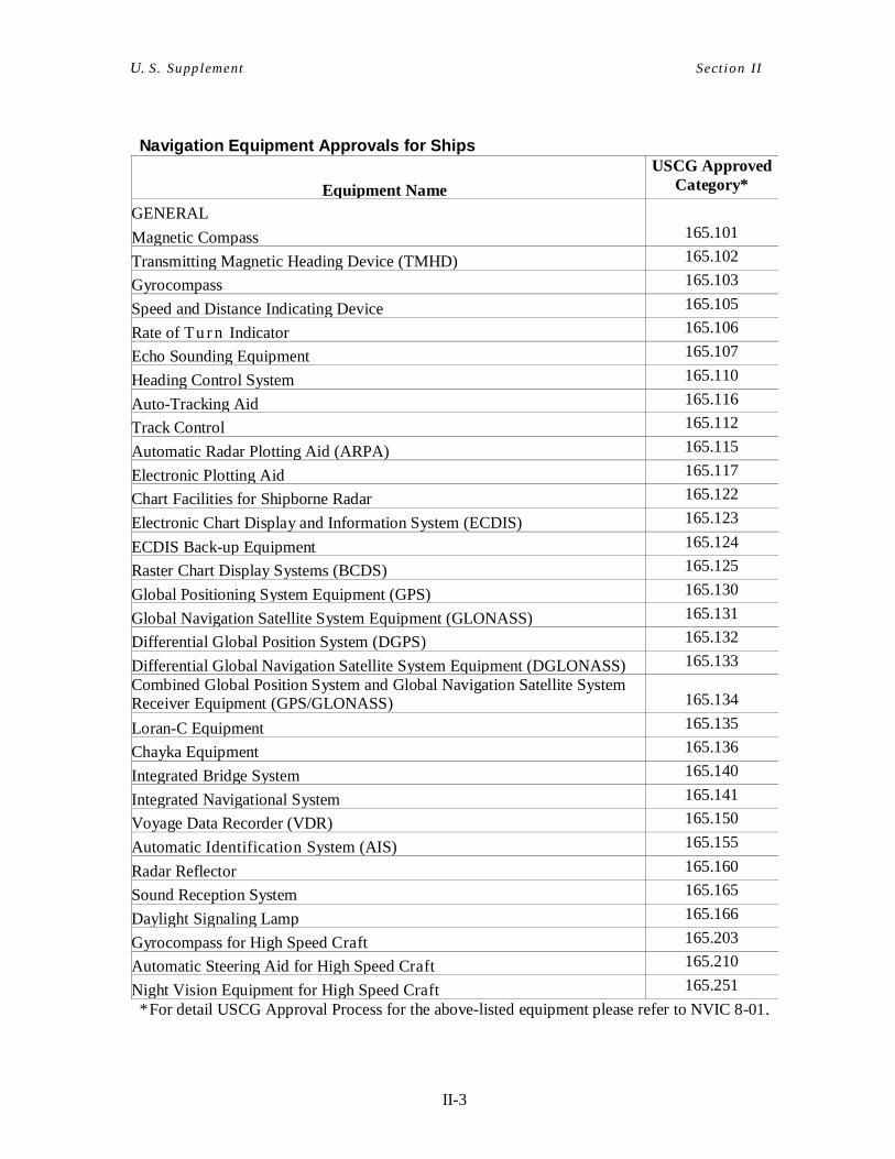
Navigation Equipment Approvals for Ships
Equipment Name
USCG Approved Category*
GENERAL
Magnetic Compass 165.101
Transmitting Magnetic Heading Device (TMHD) 165.102
Gyrocompass 165.103
Speed and Distance Indicating Device 165.105
Rate of Tu rn Indicator 165.106
Echo Sounding Equipment 165.107
Heading Control System 165.110
Auto-Tracking Aid 165.116
Track Control 165.112
Automatic Radar Plotting Aid (ARPA) 165.115
Electronic Plotting Aid 165.117
Chart Facilities for Shipborne Radar 165.122
Electronic Chart Display and Information System (ECDIS) 165.123
ECDIS Back-up Equipment 165.124
Raster Chart Display Systems (BCDS) 165.125
Global Positioning System Equipment (GPS) 165.130
Global Navigation Satellite System Equipment (GLONASS) 165.131
Differential Global Position System (DGPS) 165.132
Differential Global Navigation Satellite System Equipment (DGLONASS) 165.133
Combined Global Position System and Global Navigation Satellite System Receiver Equipment (GPS/GLONASS) 165.134
Loran-C Equipment 165.135
Chayka Equipment 165.136
Integrated Bridge System 165.140
Integrated Navigational System 165.141
Voyage Data Recorder (VDR) 165.150
Automatic Identification System (AIS) 165.155
Radar Reflector 165.160
Sound Reception System 165.165
Daylight Signaling Lamp 165.166
Gyrocompass for High Speed Craft 165.203
Automatic Steering Aid for High Speed Craft 165.210
Night Vision Equipment for High Speed Craft 165.251
* For detail USCG Approval Process for the above-listed equipment please refer to NVIC 8-01.
II-4
U. S. Supplement Sect ion II
A. Construction – Subdivision and Stability, Machi nery and Electrical Installations
SOLAS: II-1/43 Emergency Source of Electrical Power in Cargo Ships There must be visible indicators in the machinery space to show when the automatically controlled emergency power source is supplying the emergency loads.
SOLAS: II-1/45 Electrical equipment permitted in hazardous areas “Standards not inferior to those acceptable to the Organization” means standards contained in only one of the following sources:
(a) Pt E, Ch. 7, Sec. 5 of the RINA Rules, (b) The requirements of 46 CFR 111.105, or (c) IEC 60092-502: 1999 “Electrical installations in ships – tankers” as supplemented by interpretations and additional requirements of IEC 60092-502: 1999 issued by the U.S. Coast Guard in April 2009.
B. Construction – Fire Protection, Fire Detection and Fire Extinction NOTE: As indicated in NAS.10 Rules for Fire Protection, Detection and Extinction for the Issue and Maintenance of SOLAS Certificates, RINA applies the following:
(a) Chapter II-2 of the SOLAS Convention as amended and associated Codes; (b) Additional requirements set out in NAS.10 Rules; (c) Pt C, Chapter 4 of the Rules for the Classification of Ships and relevant survey requirements as per Pt A, Ch. 3, Sec. 3, [3.4] and Sec 5, [3.8] of the RINA Rules; (d) IACS Unified Interpretations in force, as applicable; (e) IMO SOLAS Unified Interpretations, in particular those contained in MSC/Circ. 1081, MSC/Circ. 1120 and MSC/Circ. 1203, although, in this case, equivalent arrangements may also be accepted by RINA; and (f) specific requirements of the flag Administration. In this respect, interpretations hereinafter are not contained in RINA Rules and will be applied.
We will also verify and take in duly account any other relevant interpretation issued by the Flag (i.e. the USCG MSC SOLAS Plan Review guidance). Moreover, for passenger ships subject to SOLAS, RINA applies those interpretations developed in the light of the Outline of Cooperation between RINA and USCG when these interpretations are approved by USCG.
SOLAS: II-2/7.2 Fixed Fire Detection and Fire Alarm Systems FSS Code Chapter 9
II-5
U. S. Supplement Sect ion II
Fire protection systems must be USCG approved equipment. A conductor must not be used as a common r e t ur n from more than one zone. Each connection box must be constructed in accordance with NEMA 250 Type 4 or 4X, or IEC IP56 requirements (46 CFR 113.10-7). There must be at least two sources of power for the electrical equipment of each fire detecting and alarm system. The nor ma l source must be the main power source. The other source must be the emergency power source or an automatically charged battery. If the other source is an automatically charged battery, the charger must be supplied from the emergency power source. Upon loss of power to the system from the normal source, the system must be automatically supplied from the other source. The capacity of each branch circuit providing power to a fire detection or alarm system must not be less than 125 percent of the maximum load. Each fire detecting zone must not include spaces on more than one deck, except: (a) Adjacent and communicating spaces on different decks in the ends of the vessel having a
combined ceiling area of not more than 279 m2 (3000 square feet). (b) Isolated rooms or lockers in such spaces as mast houses, wheelhouse top, etc., which are
easily communicable with the area of the fire-detecting circuit to which they are connected.
(c) Systems with indicators for individual spaces. The fire detecting zone must not contain more than 50 protected rooms or spaces. The system must visually indicate the zone in which the alarm originated. The detectors, control panel, manual call points and alarms must be listed in the approved component list for the USCG approved system. The fire detecting system must be used for no other purpose, except it may be incorporated with the manual alarm system. A framed chart or diagram must be installed in the wheelhouse or control station adjacent to the detecting cabinet indicating the location of the detecting zones and giving operating instructions.
SOLAS: II-2/7.4 Fixed Fire Detection and Fire Alarm Systems – Protection of Machinery Spaces
The fire control station must include an indicating unit or a fire alarm annunciator that indicates the machinery space that is on fire.

II-6
U. S. Supplement Sect ion II
SOLAS: II-2/7.2 & Fixed Fire Detection and Fire Alarm Systems – FSS Code Installation Requirements Chapter 9.2.4 A sufficient number of call points must be employed such that a person escaping from any space would find an alarm box convenient on the normal route of escape. The manual alarm system must be used for no other purpose, except it may be incorporated with the fire detecting system. Manual fire alarm boxes shall be clearly and permanently marked “IN CASE OF FIRE BREAK GLASS” in at least 12.5 mm (1/2 in) letters.
Detector spacing shall be in accordance with the manufacturer’s recommendation. Detector spacing in spaces with ceilings greater than 3 m (10 ft) must be corrected in accordance with NFPA 72E.
SOLAS: II-2/9.2.3.1 Structural Fire Protection – Method of Protection in Accommodation Area
Only Method IC shall be used.
SOLAS: II-2/9.2.3.3 Fire Integrity of Bulkheads and Deck In accordance with 46 CFR 112.05-5(e) or 127.220, no compartment that has an emergency power source or its vital components may adjoin a Category A machinery space or those spaces containing the main source of electrical power and its vital components.
SOLAS: II-2/9.3.1 “A” Class Divisions Penetrations
Non-ducted ventilation arrangements are to comply with the guidance provided in NVIC 9-97.
SOLAS: II-2/9.7.3 Duct Penetrations A large duct may not be subdivided into multiple smaller ducts when passing through a fire boundary to avoid the requirement to install automatic fire dampers.
SOLAS: II-2/10.2.1.5 Fire Fighting, Fire Mains and Hydrants – Number and Position of Hydrants
At each fire hose valve there shall be marked in not less than 50 mm (2 in) red letters and figure: “FIRE STATION.”
II-7
U. S. Supplement Sect ion II
SOLAS: II-2/10.2.3.1.1 Fire Fighting, Fire Mains and Hydrants, Fire Hoses and Nozzles – Fire Hoses
Each section of fire hose shall be lined commercial fire hose that conforms to Underwriters’ Laboratories, Inc. Standard 19 or Federal Specification ZZ-H-451E.
SOLAS: II-2/10.2.3.2.1 Fire Fighting, Fire Mains and Hydrants, Fire Hoses and Nozzles – Fire Hoses
The minimum hydrant and hose size shall be 40 mm (1.5 in.). On passenger and cargo ships over 1500 gross tons, the minimum hydrant and hose size for interior and exterior locations is 65 mm (2.5 in.). For interior locations, where 65 mm (2.5 inch) hydrants and hose are required, two 40 mm (1.5 inch) outlets with two 40 mm, (1.5 inch) hoses supplied through a siamese connection may be substituted. On tanks hips over 125 m (400 ft) (L.O.A.), the minimum hydrant and hose size for exterior locations is 65 mm (2.5 in.). Where 65 mm (2.5 inch) hydrants and hose are required, two 40 mm (1.5 inch) outlets with two 40 mm, (1.5 inch) hoses supplied through a Siamese connection may be substituted. Please note that two hoses are required at exterior fire stations equipped with Siamese fittings. Where two 40 mm (1.5 inch) hydrants and hoses are permitted in lieu of one 65 mm (2.5 inch) hydrant and hose, both of the outlets operating simultaneously are to be considered as a single outlet for the purpose of complying with the minimum number of jets criteria for fire pump capacity.
SOLAS: II-2/10.2.3.3 Fire Fighting, Fire Mains and Hydrants, Fire Hoses and Nozzles – Nozzles
Nozzles must be USCG approved equipment.
SOLAS: II-2/10.3 & Portable Fire Extinguishers – Fire Extinguishers FSS Code Chapter 4
Fire extinguishers must be USCG type-approved equipment.
SOLAS: II-2/10.4 & Fixed Fire-Extinguishing Systems – Fixed Gas Fire- FSS Code Extinguishing Systems Chapter 5 Carbon dioxide and clean agent systems, such as FM200, Novec 1230, or Halon substitutes, etc are to be USCG Type Approved. The design and installation must be in accordance with the USCG Type Approved manufacturer's manual.
II-8
U. S. Supplement Sect ion II
SOLAS: II-2/10.4 Fixed Deck Foam Systems & FSS Code Chapter 14 The system must be USCG approved equipment and must comply with the manufacturer’s approved Design, Installation, Operation and Maintenance Manual that meets Chapter II-2, Regulation 10.4 of SOLAS and the following supplemental requirements: Controls Complete, but simple instructions for the operation of the system shall be located in a conspicuous place at or near the controls. The deck foam system must be capable of being actuated, including introduction of foam to the foam main, within three minutes of notification of a fire. Piping All piping, valves, and fittings of ferrous materials shall be protected inside and outside against corrosion unless specifically approved otherwise. All piping, valves, and fittings shall be securely supported, and where necessary, protected against injury. Drains and dirt traps shall be fitted where necessary to prevent the accumulation of dirt or moisture. Piping shall not be used for any other purpose than firefighting, drills and
testing. Discharge Outlets
At least one mounted foam appliance shall be provided for each required foam station. Markings Foam apparatus, the control cabinets or spaces containing valves or manifolds for the various fire-extinguishing systems shall be distinctly marked in conspicuous red letters at least 50 mm (2 in) high “FOAM FIRE APPARATUS”. Foam Concentrates Only foam concentrates listed in the USCG type approval shall be used.
II-9
U. S. Supplement Sect ion II
SOLAS: II-2/10.4.1.1.3, Fixed Pressure Water Mist Fire-Extinguishing Systems 10.5 & in Machinery Spaces FSS Code Chapter 7 Water mist systems are to be USCG Type Approved. Design and installations must be in accordance with the USCG Type Approved manual. “Equivalent” machinery space water mist installations must comply with IMO MSC/Circ.1165. A fixed pressure water-spraying, fire-extinguishing system is not acceptable by the USCG except for lamp lockers, paint lockers and pump rooms. Where installed in these spaces, it shall comply with Chapter 7 of the FSS Code, and the following: All piping, valves and fittings shall meet the applicable requirements of Pt C, Ch 1, Sec 10 of the RINA Rules as modified by this supplement.
SOLAS: II-2/10.5.4 Fire-Extinguishing Arrangements in Machinery Spaces – Other Machinery Spaces – Incinerator Space
An enclosed space containing an incinerator shall be considered a machinery space of category A, and therefore, shall be provided with fire detection and fixed fire-extinguishing systems in accordance with IMO Resolution MEPC.76(40), “Standard Specification for Shipboard Incinerators” for the incinerator and waste storage spaces.
SOLAS: II-2/10.6 Automatic Sprinkler, Fire Detection and Fire Alarm Systems for Accommodation and Service Spaces
Automatic sprinkler systems are also to comply with National Fire Protection Association (NFPA) Standard 13-1996. Where SOLAS Reg. II-2/12 and NFPA Std. 13 have similar requirements, the higher standard is to be satisfied. The following supplemental requirements apply: The sprinkler heads, alarms, dry pipe valves, and actuating mechanisms shall be listed or approved by a recognized independent testing lab. The control cabinets or spaces containing valves or manifolds shall be distinctly marked in conspicuous red letters at least 50 mm (2 in) high “AUTOMATIC SPRINKLING SYSTEM.”
SOLAS: II-2/10.10.3 Storage of Fireman’s Outfits Lockers or spaces where emergency equipment is stowed shall be marked: “EMERGENCY EQUIPMENT”.
II-10
U. S. Supplement Sect ion II
SOLAS: II-2/13 Means of Escape The doors giving access to either of the two required means of escape shall not be lockable, except that crash doors or locking devices, capable of being easily forced in an emergency, may be employed provided that a permanent and conspicuous notice giving instructions on how to open the door or the lock is attached to both sides of the door. This paragraph shall not apply to outside doors to deckhouses where such doors are locked by key only, and such key is under control of one of the vessel’s officers. All public spaces having a deck area of over 28 sq. meters (301 sq. feet) shall have at least two exits. Where practicable, the exits shall give egress to different corridors, spaces, or rooms to minimize the possibility of one incident blocking both means of escape. Maximum clear width and inclination for stairs shall comply with 46 CFR 72.05-20 (p) & (s). In general, curved, spiral, or winding stairways shall not be permitted.
SOLAS: II-2/13 Miscellaneous Items Small rooms or spaces having a secondary means of escape which is not obviously apparent shall have a suitable sign in red letters “EMERGENCY EXIT” directing attention to such escape. C. Life-Saving Appliances and Arrangements (This s upplement entry is
intended to add clarity to the various terms used b ut not clearly defined in SOLAS.)
NOTE: Life saving appliances are verified when statutory duties on behalf of the Flag Administration are carried out. The following interpretatations will be taken into consideration in this respect. We will also verify the existence of any other relevant interpretation issued by the Flag.
SOLAS: III/3 Definitions “Accommodation” means a cabin or other covered or enclosed place intended to carry persons. Each place where passengers are carried is considered an accommodation, whether or not it is covered or enclosed. Accommodations include, but are not limited to halls, dining rooms, mess rooms, lounges, corridors, lavatories, cabins, offices, hospitals, cinemas, game and hobby rooms, and other similar spaces open to persons on board. “Embarkation station” means the place where a survival craft is boarded. “Fleet angle for a wire rope leading to a winch drum” means the angle included between an imaginary line from the lead sheave perpendicular to the axis of the drum and the line formed by the wire rope when led from the lead sheave to either extremity of the drum.
II-11
U. S. Supplement Sect ion II
“Marine evacuation system” means an appliance designed to rapidly transfer large numbers of persons from an embarkation station by means of a passage to a floating platform for subsequent embarkation into associated survival craft, or directly into associated survival craft. “Muster station” means the place where the crew and passengers assemble before boarding a survival craft. “Seagoing condition” means the operating condition of the ship with the personnel, equipment, fluids and ballast necessary for safe operation on the waters where the ship operates. For bottombearing mobile offshore drilling units, the term also applies in the bottom-bearing mode, but the “lightest seagoing condition” is considered to be the highest anticipated operating condition. “Survival craft” means a craft capable of sustaining the lives of persons in distress after abandoning the ship on which they were carried. The term includes lifeboats, liferafts, buoyant apparatus, and life floats, but does not include rescue boats.
“Toxic vapor or gas” means a product for which emergency escape respiratory protection is required under subchapter 17 of the International Code for the Construction and Equipment of Ships carrying Dangerous Chemicals in Bulk (IBC Code), and in subchapter 19 of the International Code for the Construction and Equipment of Ships carrying Liquefied Gases in Bulk (IGC Code).
SOLAS: III/4 Evaluation, Testing and Approval of Li fe-Saving Appliances and Arrangements
Life-saving appliances must be approved to the appropriate CFR, SOLAS or IMO standard. USCG approved products and systems are accepted regardless of country of manufacture. The USCG recognizes that with the Life-saving Appliances Code (LSA Code) there exists an acceptable IMO standard for approval. Equipment carrying a CG approval number issued under the US-EC or US-EFTA Mutual Recognition Agreements, discussed above the “General” section, are acceptable. A copy of the USCG acceptance letter must be provided with each piece of equipment supplied to a U.S. flag ship under these agreements. In addition, life-saving equipment accepted under the reciprocal acceptance agreement with Norway may also be used on U.S. flag vessel. The following approval series indicate approval to the SOLAS requirements:
160.017 Embarkation-Debarkation Ladders (only if marked “SOLAS 74/83”)* 160.040 Line-throwing appliances
II-12
U. S. Supplement Sect ion II
160.115 Winches (if winches for rescue boat)** 160.117 Embarkation-Debarkation Ladders* 160.118 Rigid liferafts*** 160.121 Hand red flares 160.122 Floating orange smoke signals 160.132 Davits (if davits for rescue boat)** 160.135 Lifeboats** 160.136 Rocket parachute flares 160.150 Ring life buoys* 160.151 Inflatable liferafts*** 160.155 Lifejackets 160.156 Rescue boats*** 160.157 Self-activating smoke signals 160.162 Hydrostatic release units* 160.163 Liferaft launching appliance 160.170 Liferaft automatic disengaging apparatus 160.171 Immersion suits 160.174 Thermal protective aids 160.175 Marine Evaluation Systems 160.176 Inflatable Lifejackets (SOLAS) 161.110 Floating electric water lights 161.112 Lifejacket lights 163.003 Pilot Ladders to comply with SOLAS V/17, IMO Res. A.889(21
Those items without an asterisk (*) are to be forwarded directly to the USCG for their approval.
* indicates those items for which RINA possesses USCG acceptance to conduct approval (design review and testing) work on behalf of the USCG.
** indicates items which come under the U.S. District Court Order of 31 May 1983, which declares invalid any inspection or test not conducted by or in the presence of a USCG Marine Inspector. The Order does not address pre-approved reviews. This Order remains in effect until such time as the USCG publishes a final regulation in the Federal Register removing the requirement for a USCG Marine Inspector to witness the inspections or test.
*** indicates that the USCG reserves the right to attend prototype testing of this equipment as a condition of approval. This option will normally be exercised in the case of a manufacturer seeking approval of this equipment for the first time, or for a substantially new or innovative design.
Where a particular life-saving appliance or arrangement is required, the Commandant, USCG, may accept any other appliance or arrangement that is at least as effective as that specified. If necessary, the Commandant, USCG, may require engineering evaluations and tests to demonstrate the equivalence of the substitute appliance or arrangement. Life-saving appliances carried on board the ship in addition to equipment of the type required under this part must be approved equipment or be acceptable to the cognizant USCG Officer in Charge of Marine Inspection (OCMI) for use on the ship.
II-13
U. S. Supplement Sect ion II
SOLAS: III/6 Communications Each item of radio communications equipment must be type accepted by the Federal Communications Commission.
SOLAS: III/7 Personal Life-Saving Appliances Each child-size lifejacket and immersion suit must be appropriately marked and stowed separately from adult or extended-size devices. Each lifejacket and immersion suit must be marked with the vessel’s name. Inflatable lifejackets, if carried, must all be of the same or similar design. Each lifejacket, immersion suit, and anti-exposure suit container must be marked in block capital letters and numbers with the quantity, identity, and size of the equipment stowed inside the container. The equipment may be identified in words or with the appropriate symbol from IMO Resolution A.760(18).
SOLAS: III/8 Muster List and Emergency Instructions Instructions for passengers must include illustrated instructions on the method of donning lifejackets.
SOLAS: III/11 Survival Craft Muster and Embarkation Arrangements If a davit-launched survival craft is not intended to be moved to the stowed position with persons on board, the craft must be provided with a means for bringing it against the side of the vessel and holding it alongside the vessel to allow persons to safely disembark after a drill.
SOLAS: III/13 Stowage of Survival Craft Each life-raft must be arranged to permit it to drop into the water from the deck on which it is stowed. The liferaft stowage arrangement meets this requirement if it: • is outboard of the rail or bulwark, • is on stanchions or on a platform adjacent to the rail or bulwark, or • has a gate or other suitable opening large enough to allow the liferaft to be pushed
directly overboard and, if the liferaft is intended to be available for use on either side of the vessel, such gate or opening is provided on each side of the vessel.
SOLAS: III/18 Line-Throwing Appliances In addition to the equipment approved and carried as part of the appliance, each line throwing appliance must also have an auxiliary line that:
II-14
U. S. Supplement Sect ion II
• if other than manila, has a breaking strength of at least 40 kN (9,000 lb); • if other than manila, is of a dark color or of a type certified to be resistant to
deterioration from ultraviolet light; and • is at least 450 m (1,500 ft) long.
The line throwing appliance and its equipment must be readily accessible for use, stowed in its container carried within the pilothouse or on the navigating bridge or stowed in a portable magazine chest.
SOLAS: III/33 Survival Craft Embarkation and Launch ing Arrangements
On a tank vessel certificated to carry cargoes that have a flashpoint less than 60 degrees C (140 degrees F) as determined under ASTM D93-94, each lifeboat or launching appliance of aluminum construction must be protected by a water spray system.
SOLAS: III/34 & Launching Appliances Using Falls and a Winch LSA Code VI 6.1.2 Each unguarded fall must not pass near any operating position of the winch, such as hand cranks, pay out wheels, and brake levers.
SOLAS: III/34 & Launching Appliances Using Falls and a Winch LSA Code VI 6.1.2.9 The lowering speed for a fully loaded survival craft must be not more than 1.3 meters per second (256 feet per minute). Each fall, where exposed to damage or fouling, must have guards or equivalent protection. Each fall that leads along a deck must be covered with a guard which is not more than 300 millimeters (1 foot) above the deck. Each winch drum must be arranged so the fall wire winds onto the drum in a level wrap. D. Radiocommunications
SOLAS: IV/1.4 Radiocommunication - Application
The required EPIRB must be marked with the vessel’s name.
II-15
U. S. Supplement Sect ion II
E. Safety of Navigation
SOLAS: V/22 Navigation Bridge Visibility In addition to the SOLAS implementation schedule, this regulation applies to all cargo and passenger vessels of 100 m (328 feet) or more in length and contracted for on or after September 7, 1990.
III-16
U. S. Supplement Sect ion II I
III. ADDITIONAL REQUIREMENTS NOT CONTAINED IN RINA RULES, MARPOL OR SOLAS
A. Diving Support Systems RINA shall apply 46 CFR part 197, subpart B as its standard for Diving Support Systems until further notice. B. Accommodations for Officers and Crew 1. Application
(a) The provisions of this section, with the exception of paragraph 13, shall apply to all vessels other than tankships of 100 gross tons and over contracted for on or after November 19, 1952. Vessels other than tankships of 100 gross tons and over contracted for prior to November l9, 1952, shall meet the requirements of paragraph 13.
(b) Vessels other than tankships of less than 100 gross tons shall meet the applicable
requirements of this section insofar as is reasonable and practicable.
(c) The provisions of this section, with the exception of paragraphs 14 and 15, apply to all tankships of 100 gross tons and over constructed on or after June 15, 1987.
(d) Tankships of less than 100 gross tons and manned tank barges must meet the
requirements of paragraph 14.
(e) Tankships of 100 gross tons and over constructed prior to June 15, 1987, must meet the requirements of paragraph 15.
2. Intent
(a) It is the intent of this section that the accommodations provided for officers and crew on all vessels shall be securely constructed, properly lighted, heated, drained, ventilated, equipped, located, arranged, and, where practicable, shall be insulated from undue noise and effluvia.
(b) The crew referred to herein includes all persons, except the licensed officers,
regularly employed on board any vessel. Where the requirements for the accommodation of licensed officers are not otherwise specified, they shall be of at least equivalent to that indicated herein for the crew.
(c) For the purpose of this subpart, the term “crew spaces” shall include sleeping rooms, messrooms, recreational rooms, toilet and shower spaces, etc., which are intended for the exclusive use of the crew.
III-17
U. S. Supplement Sect ion II I
3. Location of Crew Spaces
(a) Crew spaces shall be located, where practicable, so that the maximum amount of
fresh air and light are obtainable, having due regard to the service of the vessel and the requirements of other space users.
(b) Crew quarters shall not be located farther forward in a vessel than a vertical plane
located at 5 percent of the vessel’s length abaft the forward side of the stem at the designed summer load waterline. However, for vessels in other than ocean or coastwise service, this distance need not exceed 28 ft. For the purpose of this paragraph, the length shall be as defined in CFR 42.13-15 of subchapter E (Load Lines). No section of the deck of the crew spaces shall be below the deepest load line, except that in special cases, on vessels other than tankships, such an arrangement may be approved provided that in no case shall the deck head of the crew space be below the deepest load line.
(c) Hawse pipes or chain pipes shall not pass through accommodation for crew
members.
(d) There shall be no direct communication, except through solid, close fitted doors or hatches between crew spaces and chain lockers, cargo, stowage or machinery spaces.
(e) There shall be no access, vents, or sounding tubes from fuel or cargo oil tanks
opening into crew spaces, except that sounding tubes and access openings may be located in corridors.
(f) Where practicable, crew spaces shall be located entirely separate and independent
of spaces allotted to passengers or licensed officers.
4. Construction
(a) All crew spaces are to be constructed in a manner suitable to the purpose for which they are intended. The bulkheads separating the crew space from cargo and machinery spaces, lamp and paint rooms, storerooms, drying rooms, washrooms, and toilet spaces shall be made odorproof.
(b) Toilet spaces, except when provided as private or semiprivate facilities, shall be so
built, fitted, and situated, that no odor from them will readily enter other crew spaces.
(c) Where the shell or unsheathed weather decks form boundaries of crew spaces,
suitable protective coverings shall be applied to prevent formation or accumulation of moisture.
(d) Where crew spaces adjoin or are immediately above spaces such as galleys machinery spaces or casings, donkey boilerrooms, etc., they shall be suitably protected from the heat and noise.

III-18
U. S. Supplement Sect ion II I
(e) The interior sides and deckheads of crew spaces shall be covered with
enamel, paint, or other material light in color. (f) Crew spaces shall be properly drained where considered necessary. (g) All washrooms and toilet rooms shall be properly drained and so
constructed and arranged that they can be kept in a clean, workable, and sanitary condition. The scuppers shall be located in the lowest part of the space, due consideration being given to the average trim of the vessel.
5. Sleeping Accommodations
(a) Arrangements
(1) Separate sleeping accommodations are to be provided for the deck,
engine, and steward groups of the crew. (2) Each watch of seamen, firemen or similar ratings on duty in watches
is to be provided with separate sleeping room or rooms, unless the total space for accommodations makes this impracticable.
(3) Where practicable, each licensed officer shall be provided with a
separate stateroom.
(b) Size
(1) Sleeping accommodations for the crew shall be divided into rooms, no one of which shall berth more than four persons. Except on passenger ships requiring a large number of personnel in the steward’s department, rooms may be arranged to accommodate not more than 10 such persons.
(2) Each room shall be of such size that there are at least 2,78 square
meters (30 square feet) of deck area and a volume of at least 5,94 cubic meters (210 cubic feet) for each person accommodated. The clear headroom shall be not less than 1,83 meters (6 ft 3 in). In measuring sleeping quarters allocated to crews of vessels, any equipment contained therein for the use of the occupants is not to be deducted from the total volume or from the deck area.
(c) Equipment
(1) Each person shall have a separate berth and not more than one berth
shall be placed above another. The berths shall have a framework of metal or other hard, smooth material not likely to corrode or harbor vermin, and shall be so arranged that they provide ample room for easy occupancy. The overall size of a berth shall not be less than 0,76 meters (30 inches) wide by 1,93 meters (76 inches) long, except by
III-19
U. S. Supplement Sect ion II I
specialpermission of the Commandant, USCG. Where berths adjoin, they shall be divided by a partition not less than 0,45 meters (18 inches) in height. Where two tiers of berths are fitted, the bottom of the lower must not be less than 0,30 meters (12 inches) above the deck, and the bottom of the upper must not be less than 0,76 meters (2 ft 6) in both from the bottom of the lower and from the deck overhead. The berths shall not be obstructed by pipes, ventilating ducts, or other installations.
(2) A locker of metal or other hard, smooth material shall be provided for each
person accommodated in a room. Each locker shall be not less than (0,193 square meters (300 square inches) in cross section area and 1,54 meters (60 inches) high. It shall be so placed as to be readily accessible. The interior of the locker shall be so arranged as to facilitate the proper stowage of clothes.
6. Wash Spaces; Toilet Spaces; and Shower Spaces
(a) For the purposes of this section
(1) Private facility means a toilet, washing, or shower space that is accessible only from one single or double occupancy sleeping space;
(2) Semiprivate facility means a toilet, washing, or shower space that is
accessible from one or two one-to-four person occupancy sleeping spaces; and
(3) Public facility means a toilet, washing, or shower space that is not private or
semiprivate. (b) Each private facility must have one toilet, one shower, and one washbasin, all of
which may be in a single space. (c) Each semiprivate facility must have at least one toilet and one shower, which may
be in a single space. (d) Each room adjoining a semiprivate facility must have a washbasin if a washbasin
is not installed in the semiprivate facility. (e) Each tankship must have enough public facilities to provide at least one toilet, one
shower, and one washbasin for each eight persons without private facilities. (f) Urinals may be installed in toilet rooms, but no toilet required in this section may
be replaced by a urinal. (g) Each public toilet space and washing space must be convenient to the sleeping
space that it serves. (h) No public facility may open into any sleeping space. (i) Each washbasin, shower, and bathtub must have hot and cold running
III-20
U. S. Supplement Sect ion II I
water. (j) Adjacent toilets must be separated by a partition that is open at the top and
bottom for ventilation and cleaning. (k) Public toilet facilities and shower facilities must be separated. (1) Each public facility that is a toilet space must have at least one washbasin
unless the only access to the toilet space is through a washing space. (m) Each washing space and toilet space must be so constructed and arranged
that it can be kept in a clean and sanitary condition and the plumbing and mechanical appliances kept in good working order.
(n) Washbasins may be located in sleeping spaces.
7. Messrooms
(a) Messrooms shall be located as near to the galley or suitably equipped
serving pantry as is practicable, except where messroom is equipped with a steam table. The messrooms shall be of such size as to seat the number of persons normally scheduled to be eating at one time.
(b) Messrooms shall be properly equipped with tables, seats, and other
necessary equipment and shall be so arranged as to permit access to each seat.
8. Hospital Space
(a) Except as specifically modified by paragraph (f) of this section, each
vessel, which in the ordinary course of its trade makes voyages of more than 3 days duration between ports and which carries a crew of 12 or more, shall be provided with a hospital space. This space shall be situated with due regard to the comfort of the sick so that they may receive proper attention in all weathers.
(b) The hospital shall be suitably separated from other spaces and shall be used
for the care of the sick and for no other purpose. (c) The entrance shall be of such width and in such a position as to admit a
stretcher case readily. Berths shall be of metal and may be in double tier, provided the upper berth is hinged and arranged to be secured clear of the lower berth when not in use. At least one berth shall be so arranged that it can be made accessible from both sides when necessary.
(d) The hospital shall be fitted with berths in the ratio of one berth to every
twelve members of the crew or portion thereof who are not berthed in single occupancy rooms, but the number of berths need not exceed six.
III-21
U. S. Supplement Sect ion II I
(e) The hospital shall have a toilet, washbasin, and bath tub or shower conveniently
situated. Other necessary suitable equipment of such character as clothes locker, table, seat, etc., shall be provided.
(f) On vessels in which the crew is berthed in single occupancy rooms a hospital
space will not be required: provided that one room shall be designated and fitted for use as a treatment and/or isolation room. Such room shall meet the following standards:
(1) The room must be available for immediate medical use.
(2) The room must be accessible to stretcher cases.
(3) The room must have a single berth or examination table so arranged that it can be made accessible from both sides when necessary.
(4) A washbasin with hot and cold running water must be installed either in or immediately adjacent to the space and other required sanitary facilities must be conveniently located.
9. Other Spaces
(a) Sufficient facilities, depending upon the number of the crew, shall be provided where the crew may wash their own clothes. There shall be at least one tub or sink fitted with the necessary plumbing, including hot and cold running water.
(b) Clothes drying facilities or space shall be provided for the needs of the crew. (c) Recreation accommodations shall be provided. Where messrooms are used for this
purpose, they shall be suitably planned. (d) A space or spaces of adequate size shall be available on an open deck to which the
crew has access when off duty. 10. Lighting
(a) All crew spaces shall be adequately lighted. (b) Berth lights shall be provided for each member of the crew.
11. Heating
(a) All crew spaces shall be adequately heated in a manner suitable to the purpose of the space.
(b) The heating system will be considered satisfactory if it is capable of maintaining a
minimum temperature of 21°C (70°F). under normal operating conditions without undue curtailment of the ventilation.
III-22
U. S. Supplement Sect ion II I
(c) Radiators and other heating apparatus shall be so placed, and where necessary shielded, as to avoid risk of fire, danger or discomfort to the occupants. Pipes leading to radiators or heating apparatus shall be insulated where those pipes create a hazard to persons occupying the space.
12. Insect Screens
(a) Except in such areas as are considered to be insect free, provisions shall be made to
protect the crew quarters against the admission of insects. This may be accomplished by the fitting of suitable screens to ventilating skylights, air ports, ventilators, and doors to unscreened spaces and the open deck or by other methods. Insect screens are not required in air conditioned crew quarters for windows, air ports, and doors that are normally kept closed.
13. For all vessels other than tankships contracted for prior to November 19, 1952.
(a) Vessels of less than 100 gross tons, contracted for prior to November 19, 1952,
shall meet the general intent of paragraph and in addition shall meet the following requirements:
(1) Existing structure, arrangements, materials, and facilities, previously
accepted or approved will be considered satisfactory so long as they are maintained in a suitable condition to the satisfaction of the Surveyor. Minor repairs and alterations may be made to the same standard as the original construction.
(b) Vessels of 100 gross tons and over, contracted for prior to March 4, 1915, shall
meet the requirements of this paragraph.
(1) Existing structure, arrangements, materials, and facilities, previously approved will be considered satisfactory so long as they are maintained in good condition to the satisfaction of the Surveyor. Minor repairs and alterations may be made to the same standard as the original construction: Provided that in no case will a greater departure from the standards of paragraphs 2 through 12 be permitted than presently exists.
(c) Vessels of 100 gross tons and over, contracted for on or after March 4, 1915, but
prior to January 1, 1941, shall meet the requirements of this paragraph.
(1) Existing structure, arrangements, materials, and facilities, previously approved will be considered satisfactory so long as they are maintained in a suitable condition to the satisfaction of the Surveyor. Minor repairs and alterations may be made to the same standard as the original construction.
(2) Where reasonable and practicable, a minimum of one toilet, shower, and
washbasin shall be provided for each 10 members of the crew or fraction
III-23
U. S. Supplement Sect ion II I
thereof.
(3) Crew spaces shall have a volume of at least 3,39 cubic meters (120 cubic feet) and a deck area of at least 1,48 square meters (16 square feet) for each person accommodated.
(4) Each crewmember shall have a separate berth, and berths may not be placed
more than two high. (5) Each vessel, which in the ordinary course of its trade makes a voyage of
more than three days’ duration between ports and which carries a crew of 12 or more persons, shall be provided with a suitable hospital space for the exclusive use of the sick or injured. Berths shall be provided in the ratio of one berth for each twelve members of the crew or fraction thereof, but the number of berths need not exceed six.
(6) The crew spaces shall be securely constructed, properly lighted, heated,
drained, ventilated, equipped, located, and arranged, and where practicable, shall be insulated from undue noise and effluvia.
(d) Vessels of 100 gross tons and over, contracted for on or after January 1, 1941, but
prior to November 19, 1952, shall meet the requirements of this paragraph.
(1) Existing structure, arrangements, materials, and facilities, previously approved will be considered satisfactory so long as they are maintained in a suitable condition to the satisfaction of the Surveyor. Minor repairs and alterations may be made to the same standard as the original construction.
(2) Washrooms and Toilet Rooms:
(i) There shall be a minimum of one toilet, shower, and washbasin for
each 8 members of the crew or fraction thereof who are not accommodated in rooms having attached private or semiprivate facilities.
(ii) Separate facilities shall be provided for the engine room, deck, or
stewards department when the number of crew in that department, exclusive of officers, exceeds 8.
(iii) Toilet rooms shall be separate from the wash rooms. At least one
washbasin shall be installed in each toilet room. (iv) Toilets shall be provided with seats of the open front type. Urinals may
be fitted in toilet rooms, if desired, but no reduction will be made in the required number of toilets.
(v) Washbasins, showers, and bath tubs if substituted for showers, shall be
equipped with proper plumbing including hot and cold running water.

III-24
U. S. Supplement Sect ion II I
(3) Crew spaces shall have a volume of at least 120 cubic feet and a deck area of
at least 16 square feet for each person accommodated.
(4) Each crewmember shall have a separate berth, and berths may not be placed more than two high.
(5) Each vessel, which in the ordinary course of its trade makes a voyage of
more than three days duration between ports and which carries a crew of 12 or more persons, shall be provided with a suitable hospital space for the exclusive use of the sick or injured. Berths shall be provided in the ratio of one berth for each 12 members of the crew or fraction thereof, but the number of berths need not exceed six.
(6) The crew spaces shall be securely constructed, properly lighted, heated,
drained, ventilated, equipped, located, and arranged, and where practicable, shall be insulated from undue noise and effluvia.
14. Crew accommodations on tankships of less than 100 gross tons and manned tank barges
(a) The crew accommodations on all tankships of less than 100 gross tons and all
manned tank barges must have sufficient size and equipment, and be adequately constructed to provide for the protection of the crew in a manner practicable for the size, facilities, and service of the tank vessel.
(b) The crew accommodations must be consistent with the principles underlying the
requirements for crew accommodations on tankships of 100 gross tons or more.
15. Crew accommodations on tankships constructed before June 15, 1987
All tankships of 100 gross tons and over constructed before June 15, 1987 may retain previously accepted or approved installations and arrangements so long as they are maintained in good condition to the satisfaction of the Surveyor.
C. Passenger Spaces
1. Ventilation
Passenger spaces are to be provided with adequate ventilation, at least equivalent to 46 CFR 72.15
III-25
U. S. Supplement Sect ion II I
D. Navigation Safety Requirements that Apply to All Vessels
This section applies to all self propelled vessels over 1600 G. T. when operating in the navigable waters of the United States, except the St. Lawrence Seaway.
Cite: 33 CFR 164.35(g) Navigational Equipment
1. Application
(a) The provisions of this section apply to all self propelled vessels over 1600 G.T. when operating in the navigable waters of the United States, except the St. Lawrence Seaway.
2. Maneuvering Information
(a) Maneuvering characteristics must be posted prominently on a fact sheet in the
wheel house. The requirements for posting maneuvering information are found in 33 CFR 164.35. The maneuvering characteristics are to be representative of both no r ma l load, normal ballast conditions, calm weather (wind 10 kts or less), no current, deep water (at least twice the vessel’s draft), and clean hull. At the bottom of the fact sheet the following statement shall be provided:
“WARNING” The response of the (name of vessel) may be different from that listed above if any of the following conditions, upon which the maneuvering information is based, are varied:
(1) Calm weather – wind 10 knots or less, calm sea; (2) No current; (3) Water depth twice the vessel’s draft or greater; (4) Clean hull; and (5) Intermediate drafts or unusual trim.
(b) The posted characteristics shall consist of the following maneuvers:
(1) Turning Circle Diagram to both port and starboard.
• Time, distance, advance, transfer to alter course 90 deg with maximum
power settings for either full or half speeds, or full and slow speeds.
• Vessels which have essentially the same turning characteristics to both port, and starboard may substitute a turning circle in one direction only, with a note stating the other direction to be essentially the same.
• Time and Distance to Stop the vessel from either full and half speeds
while maintaining initial heading, and minimum rudder application.
III-26
U. S. Supplement Sect ion II I
• Table of Shaft RPM for a representative range of speeds should be provided for a vessel with a fixed pitch propeller.
• Table of Control Settings for a representative range of speeds for a
vessel with a controllable pitch propeller.
• Table of Effective Speeds for auxiliary maneuvering devices such as bow thrusters. This table should show the range of speeds for which the unit can be used effectively.
(c) Navigation and Vessel Inspection Circular (NVIC) 7-89 calls attention to IMO
Resolution A.601(15) “Provision and Display of Maneuvering Information Onboard Ships”, adopted 19 November 1987, and MSC/Circ. 389, “Interim Guidelines for Estimating Maneuvering Performance in Ship Design,” adopted 10 January 1985.
These provide guidance to the owner and operator concerning maneuvering performance estimation and a standardized format for presentation of ship maneuvering information to operating personnel, including pilots.
Cite: 33 CFR 164.33(2)(i) & Charts and Publications 33 CFR 164.33(3)(ii)
1. Application
(a) The provisions of this section apply to all self propelled vessels over 1600 G.T.
when operating in the navigable waters of the United States, except the St. Lawrence Seaway.
2. Requirements
(a) In addition to the requirements of SOLAS, a vessel must have a current copy of the
“U.S. Coast Pilot”, and “Tidal Current Tables”, published by the National Oceanographic Service. Further detail is provided in 33 CFR 164.33.
Cite: 33 CFR 164.41 Electronic Position Fixing Devices
See Federal Register Vol. 59, No. 56, dated March 23, 1994, page 13757 for additional guidance.
1. Application
(a) The provisions of this section apply to all self propelled vessels over 1600 G.T. and
calling at a port in the United States, including Alaska south of Cape Prince of Wales. Each vessel operated, owned, or bareboat chartered by the United States, State, or Political Subdivision, by a foreign nation, and not engaged in commerce is
III-27
U. S. Supplement Sect ion II I
exempt from this requirement. Requirements for electronic position fixing devices are found in 33 CFR 164.41.
2. Devices
(a) A Type I or Type II Loran C Receiver meeting Part 2 (Minimum Performance
Standards of the Radio Technical Commission for Marine Services (RTCM) Paper 12-78/DOD100. Each receiver installed on or after June 1, 1982 must have a label showing the n a m e and address of the manufacturer, including the following statement: “This receiver was designed and manufactured to meet Part 2 (Minimum Performance Standards) of the RTCM MPS for Loran-C Receiving Equipment.”
(b) A Satellite Navigation Receiver with automatic acquisition of satellite signals, and
position updates derived from satellite information.
(c) A system considered to meet the intent for availability, accuracy, and coverage for the U.S. Confluence Zone (CCZ) contained in U.S. “Federal Radio Navigation Plan” (Report No. DOD-No 4650.4-D or No. DOT-TSC-RSPA-80-16I).
E. Requirements in Addition to MARPOL Annexes
In order to facilitate reference, the applicable CFR cite is given for each entry.
ANNEX I
Cite: 33 CFR 151.26 Shipboard Oil Pollution Emergency Plan
For the issue of a Certificate of Inspection, the Shipboard Oil Pollution Emergency Plans (Reg. 37) outlined in IMO Res. MEPC.86(44) can only be approved by the U.S. Coast Guard (CG-533).
Cite: 33 CFR 155.205 Discharge Removal Equipment for Vessels 121,9 meters (400 Feet) or Greater in Length
Oil carrying tank vessels with a length that is at least 121,9 meters (400 ft.) must carry discharge removal equipment for on-deck spills up to 1908 liters (12 bbl). The equipment must include: sorbents, non-sparking hand scoops, containers for the recovered spillage, emulsifiers for deck cleaning, protective clothing, one non-sparking portable pump with hoses, and scupper plugs.
Cite: 33 CFR 155.210 Discharge Removal Equipment for Vessels Less than 121,9 meters (400 Feet) in Length
Oil carrying tank vessels with a length that is less than 121,9 meters (400 ft) must carry discharge removal equipment for on-deck spills up to 1113 liters (7 bbl). The equipment must include: sorbents, non-sparking hand scoops, containers for the recovered spillage, emulsifiers
III-28
U. S. Supplement Sect ion II I
for deck cleaning, protective clothing, one non-sparking portable pump with hoses, and scupper plugs.
Cite: 33 CFR 155.225 Internal Cargo Transfer Capability
Oil tankers and offshore oil barges must carry suitable hoses and reducers for internal transfer of cargo to tanks or other spaces within the cargo block, 33 CFR 155.225
Cite: 33 CFR 155.230 Emergency Towing Capability for Oil Barges
Emergency towing systems of Offshore barge must comply with the requirements of 33 CFR 155.230.
Cite: 33 CFR 155.310 Containment of Oil and Hazardous Material Cargo Discharge
Under hose connections there must be a fixed container or enclosed deck area with a mechanical means of closing the drain for that containment which has a capacity:
79,5 l (1/2 bbl) for lines no more than 5 cm (2”) 159 l (1 bbl) for lines more than 5 cm (2”) up to 10 cm (4”) 318 l (2 bbl) for lines no less than 10 cm (4”) up to 15 cm (6”) 477 l (3 bbl) for lines no less than 15 cm (6”) up to 30,5 cm (12”) 636 l (4 bbl) for lines 30,5 cm (12”) or more
Cite: 33 CFR 155.320 Fuel Oil and Bulk Lubricating Oil Discharge Containment
Under fill connections and vents there must be a fixed container or enclosed deck area with a mechanical means of closing the drain for that containment which has a capacity:
79,5 l (1/2 bbl) for vessels 300 GT or more but less than 1600 GT 159 l (1 bbl) for vessels 1600 GT or more
Cite: 33 CFR 155.380 Oily-water Separating Equipment, Bilge Alarm and Bilge Monitor Approval Standards
Oily-water separating equipment and oil content meters for bilge alarms are to be USCG approved equipment. Cite: 33 CFR 155.450 Placard Each machinery space must have a sign indicating that the discharge of oil is prohibited.
Cite: 33 CFR 155.780 Emergency Shutdown
Tank vessel must have an emergency means of stopping transfers within a vessel.
III-29
U. S. Supplement Sect ion II I
Cite: 33 CFR 155.790 Deck Lighting
Tank vessels must have a means of illuminating the deck in transfer operation work areas – 10,76 lux (1.0 foot candle) measured 0,91 meters (3 feet) above the deck – and at transfer connections – 53,82 lux (5.0 foot candle) measured 0,91 meters (3 feet) above the deck.
Cite: 33 CFR 155.800 Transfer Hoses
Transfer hoses must have burst pressure of at least 4,13 MPa (600 psi) and four times the MAWP, which must be at least 1,03 MPa (150 psi). Hose flanges must meet ANSI B16.5 or B16.24. The hoses must be marked with the MAWP, type of service, date of manufacture and the date of the last pressure test. The date of manufacture and the date of the last pressure test may be recorded in lieu of being marked on the hoses.
Cite: 33 CFR 155.1010 Response Plans – Purposes
Applies to tank vessels without regard to size. (Reg. 37 applies to tank vessels greater than 150 g.t. and all vessels greater than 400 g.t.) Applies to discharges of oil. (Reg. 37 applies to all discharges of oil.) Requires formal agreements for spill notification and cleanup. (Reg.37 requires only shipboard procedures and a shoreside contact.) Requires a geographic specific appendix for U.S. ports. (Reg. 37 requires a worldwide list.)
Cite: 33 CFR 157.03(n) Definition – Oil
Oil is not limited to petroleum and includes animal fats and other “oils.” (MARPOL regulates animal fats and vegetable oils under Annex II.)
Cite: 33 CFR 157.10b Segregated Ballast Tanks, Dedicated Clean Ballast Tanks, and Special Ballast Arrangements for Tank Vessels Transporting Outer Continental Shelf Oil
Tank vessels servicing the OCS are permitted to carry ballast water in cargo tanks. (MARPOL makes no special allowances for these sorts of vessels). See also 33 CFR 157.35 Ballast Added to Cargo Tanks
Cite: 33 CFR 157.10d Double Hulls on Tank Vessels
U.S. dates for required double hull construction are three (3) years earlier than Reg. 19 i.e. the requirement applies to ship: (a) for which the building contract is awarded after June 30, 1990; (b) that is delivered after December 31, 1993; (c) that undergoes a major conversion for which;
(i) the contract is awarded after June 30, 1990; or (ii) conversion is completed after December 31, 1993; or
(d) that is otherwise required to have a double hull by 46 U.S.C. 3703a(c).

III-30
U. S. Supplement Sect ion II I
Note: The double hull compliance dates of 46 U.S.C. 3703a(c) are set out in appendix G to this part. To determine a tank vessel's double hull compliance date under OPA 90, use the vessel's hull configuration ( i.e., single hull; single hull with double sides; or single hull with double bottom) on August 18, 1990. There is no minimum tonnage limit for applicability to vessels. (Reg. 19 applies for vessels greater than 5000 dwt.) Ships less than 5000 dwt must have both double hull and double sides.
Cite: 33 CFR 157.12 Cargo Monitor and Control System
The oil discharge monitoring and control system is to be USCG approved equipment. The ODMC system manual is also required to be approved.
Cite: 33 CFR 157.15 Slop Tanks in Tank Vessels
Should an oily water separator (OWS) be installed with a suction from a slop tank, it must be USCG Approved". 33 CFR 157.15 doesn't require a slop tank to have and OWS.
Cite: 33 CFR 157.21 Subdivision and Stability
For US Flag vessels, MARPOL damage stability requirements are applicable to the following vessels:
(a) New vessels delivered after 31 December 1977 (b) New vessels contracted after 31 December 1974, and (c) New vessels whose keels were laid (or similar stage of construction) after 30 June
1975
“New vessel” (defined in 157.03) applies to vessels as under contract, constructed, or completed between 1975/1976/1979. (Reg. 1.28.4) defines “new” as four (4) years later.)Interpretation: Interpretation: MARPOL Reg. 18.5 Segregated ballast tanks, dedicated clean ballast tanks and crude oil washing. Vessels less than 150 m in length: The U.S. has not adopted the requirements in Appendix 1 to Annex I which addresses segregated ballast for vessels less than 150 m in length. Determination under this regulation must be made by the Commandant, USCG. Interpretation: MARPOL Reg. 19.4 Prevention of oil pollution in the event of collision or stranding. Mid-deck tankers: The U.S. has not ratified that the mid-deck design is equivalent to a double hull. Interpretation: MARPOL Reg. 20 Prevention of oil pollution in the event of collision or stranding. Determinations by the Administration: The Commandant, USCG, makes determinations on behalf of the U.S.
III-31
U. S. Supplement Sect ion II I
Interpretation: MARPOL Reg. 28.1.3 Subdivision and Stability. Stability for vessels under 100 m (328 feet): The Commandant, USCG, makes determinations concerning the relaxation requirements for vessels less than 100 m (328 feet) if the standards for a vessel 150 m (492 feet) or longer would impair the operational qualities of the ship. ANNEX II Navigation and Vessel Inspection Circular No. 03-06 provides “Guidance on implementation of revisions to MARPOL Annex II and the IBC Code,” which is considered to be U.S. Coast Guard policy.
Cite: 33 CFR 151.27 Shipboard Marine Pollution Emergency Plan for NLS For the issue of a Certificate of Inspection, the Shipboard Marine Pollution Emergency Plans for Noxious Liquid Substances (NLS) (Reg. 16) outlined in IMO Res. MEPC.85(44) can only be approved by the U.S. Coast Guard (CG-533). ANNEX III (no differences) ANNEX IV (NOT ADOPTED) COMPARISON OF USCG RULES TO MARPOL
Cite : 33 CFR 159 Marine Sanitation Devices (MSDs) All vessels must be installed with either an operable MSD which controls the discharged fecal coliform bacteria count to 200 per 100 ml and the suspended solids to 150 mg/l, which is certified by the Commandant, USCG or with an operable MSD which retains the sewage on board. ANNEX V
Cite: 33 CFR 151.51 Garbage Pollution – Applicability The U.S. applies Annex V to U.S. public vessels after January 1, 1994. MARPOL does not generally apply to public vessels.
Cite: 33 CFR 151.55 Garbage Pollution – Record Keeping Requirements
Garbage Pollution Record Keeping is requested for
(a) Every manned oceangoing ship (other than a fixed or floating platform) of 400 gross tons and above that is engaged in commerce and that is documented under the laws of the United States or numbered by a State.
(b) Every manned fixed or floating platform subject to the jurisdiction of the United States.
III-32
U. S. Supplement Sect ion II I
(c) Every manned ship that is certified to carry 15 passengers or more engaged in international voyages.
Cite: 33 CFR 151.57 Garbage Pollution – Waste Management Plans Garbage Pollution Waste Management Plans are requested for
(a) Each manned oceangoing ship (other than a fixed or floating platform) of 12,2 meters (40 feet) or more in length that is documented under the laws of the United States or numbered by a state and that either is engaged in commerce or is equipped with a galley and berthing.
(b) Each manned fixed or floating platform that is
(i) Documented under the laws of the United States; or
(ii) Operating under the authority of the United States, including, but not limited to, a lease or permit issued by an agency of the United States.
Cite: 33 CFR 151.59 Garbage Pollution – Placards
Garbage Pollution Placards are requested for
(a) Each manned U.S. ship (other than a fixed or floating platform) that is 7,92 meters (26 feet) or more in length.
(b) Each manned floating platform in transit that is
(i) Documented under the laws of the United States; or (ii) Operating under the authority of the United States, including, but not limited to, a
lease or permit issued by an agency of the United States. ANNEX VI U.S. Coast Guard policy with respect to the issue of MARPOL Annex VI certificates required to be carried aboard a vessel is contained in CG-543 Policy Letter 09-01.
Cite: 46 CFR 63.25-9 Incinerators Each incinerator installed on or after March 26, 1998 must meet the requirements of IMO Resolution MEPC.76(40), or equivalent. A U.S. Coast Guard Certificate of Approval is required for each incinerator. Conformance to IMO.
IV-1
U. S. Supplement Sect ion IV
IV. ACP SURVEYS AFTER CONSTRUCTION
CHECKLIST FOR CARGO SHIP SAFETY CONSTRUCTION SURVEY S
TO BE DONE IN CONJUNCTION WITH INITIAL, ANNUAL AND RENEWAL CARGO SHIP SAFETY CONSTRUCTION SURVEYS 1. On vessels not assigned with additional class notation AUT-CCS, automation systems for
propulsion and auxiliary boilers is tested with USCG-approved procedures and found satisfactory.
2. The vessel’s Chief Engineer certify that all aspects of the vessel’s automated equipment
has been routinely and recently tested using the USCG-approved Periodic Automation Test Safety Procedure (or approved by RINA on behalf of USCG) and found satisfactory.
3. The RINA Class Annual Automation Survey satisfactorily is carried out, utilizing the
USCG Periodic Automation Test Safety Procedure 4. It is confirmed that vessels with unattended Machinery Spaces had a planned
maintenance program, including maintenance and repair manuals and routine maintenance and checksheets?
5. The remote controls of valves in hull penetrations are randomly tested. Proper operation
of reach rods, control actuators and function indicators are randomly verified and found satisfactory. At the cargo safety construction renewal survey a more detailed examination to the satisfaction of the surveyor is conducted.
6. Throttle control apparatus is demonstrated in manual and power modes at all stations and
related alarms and trips are verified operational. 7. A general examination is conducted of ladders, handrails, ramps, catwalks,
accommodation ladders, and protective guards on machinery to ensure these items are in good general repair and suitable to protect personnel.
8. Draft marks, vessel name and hailing port are affixed and displayed. 9. Machinery space tank tops and bilges are examined for accumulation of oil or other
substances that could pose a fire hazard and unsafe condition, if any, are corrected. 10. Power operated trucks are marked with testing laboratory mark designation as specified
in 46 CFR 35.70-74 and 46 CFR 78.80 or 46 CFR 97.70-7 as applicable and suitable for the hazard classification in the space employed.
11. An operational test is conducted of the main and emergency bilge pump suctions. 12. The main and auxiliary piping systems are examined externally and found free of
apparent leakage.
IV-2
U. S. Supplement Sect ion IV
The flexible non-metallic expansion pieces in the circulating system are identifiable by manufacturer and verified by the Chief Engineer to have less than 10 years of service.
13. The vessel’s Master and Chief Engineer confirm that the vessel has no forms CG-835 or
other conditions that needed to be communicated to RINA Surveyor. 14. The crew does not report, nor do I see any unsafe or unsanitary conditions of a concern. 15. If any of the above questions is answered “No,” the local OCMI must be informed before
the vessel sails. The source of the information is to be kept confidential.

IV-3
U. S. Supplement Sect ion IV
CHECKLIST FOR CARGO SHIP SAFETY EQUIPMENT SURVEYS TO BE DONE IN CONJUNCTION WITH INITIAL, ANNUAL AND RENEWAL CARGO SHIP SAFETY EQUIPMENT SURVEY I. Fire Hose Testing 1. All fire hoses are hydrostatically tested to the maximum fire pump pressure to which
they may be exposed but not less than a minimum pressure of 6.9 bar (100 psi). Note: the safety equipment certificate may not be issued or endorsed if this is not done.
II. Liferaft Servicing
Note: Lack of certification is a No Sail item and the local OCMI must be contacted.
1. USCG field offices perform initial service facility approval and periodic spot checks,
but third parties may be substituted. A new sticker system on the liferaft itself should be used in conjunction with the certificate to determine proper servicing.
2. Liferaft certificates indicate current servicing by a USCG approved facility. The
information must contain the port of servicing and the date of servicing. III. Lifeboat Operational Tests 1. Proper operation of the propelling gear and/or motors is demonstrated. (IMO allows
this testing to be carried out while the boat is secured in the falls.) a. The CG inspectors will have a crew proficiency test to conduct during their
boarding. At that time, the crew must operate each boat in the water, and the following tests will be carried out.
b. The USCG will accept load tests done by RINA. 2. Each motor lifeboat and hand-propelled boat is operated at full speed both ahead and
astern. 3. Each installed system, such as any powered bilge pump or water spray system is
successfully operated. 4. Compass readings are compared with several known bearings. 5. Each air tank buoyancy unit is visually inspected and appears fit for service. 6. Water tanks are inspected and confirmed watertight. 7. Batteries for engine starting and searchlights have a means for recharging, which are in
satisfactory condition.
IV-4
U. S. Supplement Sect ion IV
8. The condition and quantity of survival equipment is checked as per the RINA checklists and manuals.
IV. Advice for Lifeboat Weight Tests 1. The USCG has requirements in addition to SOLAS. Weight testing of the lifeboats is
required by USCG during each inspection for certification and whenever the falls are turned end-for-end or renewed.
2. The references for USCG lifeboat testing and inspection are:
a. Title 46, Code of Federal Regulations Part 199.45 and b. Marine Safety Manual, Vol. 11, Section 6.R
3. The CFR contains the performance standard required, while the process used to verify
compliance with the standard is found in the Marine Safety Manual (MSM).

IV-5
U. S. Supplement Sect ion IV
CHECKLIST FOR CARGO SHIP ENVIRONMENTAL SURVEYS TO BE DONE IN CONJUNCTION WITH INITIAL, ANNUAL AND RENEWAL MARPOL ANNEX I SURVEY
1. Marine Portable Tanks (MPTs), are labeled showing compliance with IM 101, IM 102, or exemption issued according to 49 CFR 107 (Subpart B) and installed and tested IAW 46 CFR 64.
2. The Vessel’s Fuel and Bulk Oil Containment arrangements are examined and found to be in compliance with 33 CFR 155.320.
3. The Vessel’s Oil Placards indicating that discharge of oil is prohibited are examined and found in each machinery space and at control stations for ballast and bilge controls.
4. Cargo Discharge Containment arrangements are examined and found to be in compliance with 33 CFR 155.310.
5. Emergency Shutdown of cargo transfers within the vessel are examined and found to be in compliance with 33 CFR 155.780.
6. On tank vessels, is the illumination of the deck in transfer operation work areas and at transfer connections adequate? 33 CFR 155.790(b)
7. Cargo Transfer Hose testing is witnessed or an affidavit sighted from a responsible individual, that hoses had been hydrostatically tested and marked according to 33 CFR 155.800. Pipe and manifold labeling is checked for accuracy and legibility.
8. Tank Vessel’s approved OPA Vessel Response Plan complying with 33 CFR 155.1010 is verified onboard.
9. Vessel’s approved shipboard oil pollution emergency plan (SOPEP) (MARPOL ANNEX 1, REGULATION 26), is verified on board.
10. Tank Vessel of length 400 feet (121.92 m) or greater is examined and found to have Oil Discharge Removal Equipment complying with 33 CFR 155.205 for on-deck spills up to 12 bbl stowed in marked location.
11. Tank Vessel of length less than 400 feet (121.92 m) is examined and found to have Oil Discharge Removal Equipment complying with 33 CFR 155.210 for on-deck spills up to 7 bbl stowed in marked location.
12. Vessel is examined and found to have oil discharge removal equipment complying with 33 CFR 155.220 (Permit issued or NLS Certificate issued) and COI authorized C and D NLS Cargoes.
13. Tank Vessel’s Cargo Internal Transfer Equipment is examined and found to be in compliance with 33 CFR 155.225.
14. Vapor control systems are examined for compliance with 46 CFR 39, and a representative sample of alarms are tested and found to be in proper operation.

IV-6
U. S. Supplement Sect ion IV
NOTE: Tank Vessel carrying animal fats and “other oils” are considered as a vessel carrying “oil” in accordance with 33 CFR 157.03(n). TO BE DONE IN CONJUNCTION WITH INITIAL, ANNUAL AND RENEWAL MARPOL ANNEX IV (Sewage) SURVEYS
1. Marine Sanitation Devices examined, devices is found to be certified in accordance with 33 CFR 159 as Type I, II, or III, as appropriate, and continue to be in satisfactory operating condition and arrangement.
TO BE DONE IN CONJUNCTION WITH INITIAL, ANNUAL AND RENEWAL MARPOL ANNEX V (Garbage) SURVEYS
1. The Vessel is verified to be keeping Garbage Disposal Records required by 33 CFR 151.55.
2. The Vessel’s approved Waste Management Plan complying with 33 CFR 151.57 is verified onboard.
3. Placards describing prohibited waste discharges as required by CFR 151.59 are verified as posted.
V-1
U. S. Supplement Sect ion V
V. NEW CONSTRUCTION SURVEYS CHECKLIST ON ACP CLASSIFICATION SURVEYS
TO BE DONE IN CONJUNCTION WITH ISSUANCE OF THE INTE RIM CLASSIFICATION CERTIFICATE 1. Are communications cables routed to avoid high risk fire areas and are telephone
installations in the weather located in a watertight enclosure with an external audible signaling device?
2. Is the stop control for the emergency generator located only in the room containing the
emergency generator? 3. Are the additional requirements for vessels carrying hazardous cargoes complied with
and tested as necessary? 4. Are valves verified to meet the requirements of positive shutoff category A or category
B in the required piping system? 5. Sounding tubes, where fitted to oil tanks, are verified to not have perforations or
openings throughout their length? 6. For vessels with automatic or remote control and monitoring systems, are the following
approved manuals found on board: a. Qualitative Failure Analysis (propulsion controls, monitoring and alarm systems,
automated electric power management system, all other automated systems that may potentially constitute a safety hazard (e.g. stabilization systems, integrated propulsion/steering systems)
b. Planned Maintenance Program c. Design Verification Test Procedures (all automated systems)
7. Is the steering failure alarm tested and found satisfactory? 8. On tank vessels, are the additional requirements for cargo vapor emission control
systems verified? 9. Are all required placards, instructions, and identification labels found to be in
accordance with the supplement?
VI-1
U. S. Supplement Sect ion VI
VI. PASSENGER VESSELS – SOLAS INTERPRETATIONS NOT ADDRESSED BY RINA RULES Cite: II-1/13 Openings in Watertight Bulkheads Below the Bulkhead Deck
in Passenger Ships VI-2 Cite: II-1/17 Internal Watertight Integrity of Passenger Ships Above the
Bulkhead Deck VI-2 Cite: II-1/42 Emergency Source of Electrical Power in Passenger Ships VI-2 Cite: II-2/13 Means of Escape VI-2 Cite: II-2/20.6 Protection of Special Category Spaces VI-3 Cite: II-2/20.6 & Protection of Special Category Spaces II-2/20.3.1.3 VI-4 Cite: III/21 Survival Craft and Rescue Boats VI-4 Cite: III/22 Personal Life-Saving Appliances VI-4 Cite: III/22.3 Personal Life-Saving Appliances – Lifejacket Lights VI-4 Cite: III/22.4.1.2 Personal Life-Saving Appliances – Immersion Suits and
Thermal Protective Aids VI-5 Cite: III/23 Survival Craft and Rescue Boat Embarkation Arrangements VI-5
VI-2
U. S. Supplement Sect ion VI
VI. PASSENGER VESSELS – SOLAS INTERPRETATIONS NOT ADDRESSED BY RINA RULES ____________________________________________________________________________ Cite: II-1/13 Openings in Watertight Bulkheads Below the Bulkhead Deck in
Passenger Ships All watertight doors in subdivision bulkheads shall be numbered conspicuously on both sides on an etched plate or equivalent in not less than 10 mm (3/8 in) letters and figures “W.T.D. 1,” “2,” “3,” etc. If stenciled or similar notice is used, the letters and figures shall be at least 25 mm (1 in) high. If the construction is such that the number cannot be seen with the door in the open position, a similar number shall be placed on the frame or other location immediately adjacent to the door. All watertight door remote control stations shall be marked in the same manner, and in addition, the direction of operation of the lever or wheel to open and close the door shall be conspicuously marked. ____________________________________________________________________________ Cite: II-1/17 Internal Watertight Integrity of Pass enger Ships Above the Bulkhead
Deck In Paragraph 1, arrangements to ensure the watertight integrity of the structure above the bulkhead deck must adhere to the guidance of MSC/Circ. 541 – Guidance notes on the integrity of flooding boundaries above the bulkhead deck of passenger ships should be followed for proper application of SOLAS Chapter II-1 in force before January 1, 2009. ____________________________________________________________________________ Cite: II-1/42 Emergency Source of Electrical Power in Passenger Ships There must be visible indicators in the main machinery space to show when the automatically controlled emergency power source is supplying the emergency loads. ____________________________________________________________________________ Cite: II-2/13.3.2.6.1 Means of Escape Stairways on new passenger ships shall comply with the following: The two means of escape required by Regulation 13, paragraphs 3.2.1 and 3.2.2 shall be as remote as possible to minimize the possibility of one incident blocking both escapes. Vertical ladders and deck scuttles shall not in general be considered as one of the required means of escape. However, where it is demonstrated that the installation of a stairway would be impracticable, a vertical ladder may be used as the second means of escape. Doors giving access to either of the two required means of escape shall not be lockable, except that crash doors or locking devices, capable of being easily forced in an emergency, may be employed provided that a permanent and conspicuous notice giving instructions on how to open the door or lock is attached to both sides of the door. Vertical communication shall be provided between weather decks by means of permanent inclined ladders. Where ladders are for the exclusive use of the crew, and do not form part of the escape route, vertical ladders may be employed.
VI-3
U. S. Supplement Sect ion VI
Small rooms or spaces having a secondary means of escape which is not obviously apparent shall have a suitable sign in red letters “EMERGENCY EXIT” directing attention to such escape. Readily accessible enclosed stairway is defined to mean it must either be in the MVZ or immediately adjacent to the zone such that entrance into the stairway does not require entering into the adjoining zone to gain access to the stairway in accordance with the interpretations of SOLAS II-2/9.2.2.1 in MSC/Circ 1120. In addition to the requirements of paragraph 3.2.1.2, the requirements of paragraph 7.3.1 apply to corridors which are 6 feet or more in width in all passenger vessels. ____________________________________________________________________________ Cite: II-2/20.6 & II-2/20.3.1.3 Protection of Special Category Spaces The mandatory indication for loss/failure of ventilation in spaces specially suitable for vehicles shall be a visual and audible alarm marked with a conspicuous sign in at least 12 mm (1/2 in) letters “VENTILATION FAILURE IN VEHICLE SPACE.” ____________________________________________________________________________ Cite: III/22 Personal Life-Saving Appliances Immersion suits and thermal protective aids are required to be provided for persons accommodated in totally or partially enclosed lifeboats, unless the vessel operates only on routes between 32 degrees north and 32 degrees south latitude. ____________________________________________________________________________ Cite: III/22.4.1.2 Personal Life-Saving Appliances – Immersion Suits and Thermal
Protective Aids The warm climate exemption in Regulation 22.4.1.2 applies to ships operating only on routes between 32 degrees north and 32 degrees south latitude. An immersion suit or anti-exposure suit of suitable size for each person is to be provided for each person assigned to a marine evacuation system crew.
VII-1
U. S. Supplement Sect ion VII
VII. IBC CODE SUPPLEMENTAL REQUIREMENTS
U.S. Interpretations and Guidance Related to the International Code for the Construction and Equipment of Ships Carrying
Dangerous Chemicals in Bulk (IBC Code) Unless otherwise noted below, RINA is authorized to interpret the expressions “left to the satisfaction of the Administration,” or similar expressions in the IBC Code pertaining to the International Certificate of Fitness for the Carriage of Dangerous Chemicals in Bulk. Navigation and Vessel Inspection Circular No. 03-06 provides “Guidance on implementation of revisions to MARPOL Annex II and the IBC Code,” which is considered to be U.S. Coast Guard policy.
Chapter 1 – General 1.1.3 USCG will handle matters relating to carriage conditions of cargoes not listed in
the IBC Code. 1.3.16 The approved closed cup flashpoint test uses the Tagliabue apparatus. 1.3.2 Generally, USCG acts as the administration for findings of equivalency. 1.5 Under this section, the Administration means the USCG.
Chapter 2 – Ship Survival Capability and Location of Cargo Tanks 2.2.2 Intact Stability shall also meet the requirements for gas carriers contained in 46
CFR Subchapter S (or equivalent) for gas carriers 46 CFR 172.165, which states:
(a) Design calculations must show that 2 inches (50 mm) of positive metacentric
height can be maintained by each tankship when it is being loaded and unloaded.
(b) For the purpose of demonstrating compliance with the requirements of
paragraph (a) of this section, the effects of the addition of water ballast may be considered.
2.2.3 Free surface effects shall be taken into account according to Pt B, Ch 13, Sec 2 of
RINA Rules 2.3.3 The valve shall be in accordance with RINA rules. 2.8.2 No dispensations for smaller ships will be allowed. 2.9.2.3 Residual stability should not be less than that allowed in 2.9.3.
VII-2
U. S. Supplement Sect ion VII
Chapter 3 – Ship Arrangements 3.4.4 Smaller dimensions are not permitted unless authorized by the USCG. 3.7.2 Toxic cargoes cannot be unloaded bow or stern unless authorized by the USCG. 3.7.3.5 Alternative arrangements must be authorized by the USCG.
3.7.4 USCG must authorize relaxations.
Chapter 4 – Cargo Containment 4.1.3 Recognized standard is RINA rules, that apply for tank testing. 4.1.4 Recognized standard is ASME Code Section VIII, Division 1 or 2, that
applies for pressure vessel design.
Chapter 5 – Cargo Transfer 5.1.1 Piping classification standards are listed in 46 CFR 56.04 and piping design
standards are listed in 46 CFR 56.07. 5.1.3 Flanges, valves, and fittings should meet applicable standards of the ASME. 5.2.1 Relaxations must be authorized by the USCG. 5.2.2 Exceptional cases should be authorized by the USCG. 5.2.3 Piping joint selection and limitations are listed in 46 CFR 56.30. 5.2.4 Bellows are not permitted. 5.2.5 Welding, post weld heat treatment and non-destructive testing standards are listed
in 46 CFR 56.70, 56.85, and 56.95, respectively. 5.4.1 Relaxations must be authorized by USCG. 5.7 Hoses must have either full threaded connections; ANSI B16.2, 16.24, or B16.31
flanges; or Class 1 quick connect couplings that meet ASTM F1122 and marked “C1-1.” The hose should be marked with the date of manufacture and be in good condition (no loose covers, kinks, bulges, soft spots, or gouges/cuts which penetrate the hose reinforcement.) The hose should also be marked with the date of its last inspection, which should be conducted with the hose in a straight, flat, horizontal position and include a static pressure test at the maximum operating pressure.
VII-3
U. S. Supplement Sect ion VII
Chapter 6 – Materials of Construction
6.1.1 Materials must meet RINA rules.
6.3 Prohibited materials. When one of the following paragraphs of this section is referenced in Table 1 of 46 CFR part 153, the materials listed in that paragraph may not be used in components that contact the cargo liquid or vapor:
(a) Aluminum or aluminum alloys (b) Copper or copper alloys (c) Zinc, galvanized steel or alloys having more than 10 percent zinc by weight
Magnesium (d) Lead (e) Silver or silver alloys (f) Mercury
Required materials. When one of the following paragraphs of this section is referenced in Table 1 of 46 CFR part 153, only those materials listed in that paragraph may be used in components that contact the cargo liquid or vapor:
(a) Aluminum, stainless steel, or steel covered with a protective lining or coating (b) With cargo concentrations of 98 percent or greater, aluminum or stainless steel (c) With cargo concentrations of less than 98 percent, 304L or 316 stainless steel (d) Solid austenitic stainless steel (e) Stainless steel or steel covered with a suitable protective lining or coating
Chapter 7 – Cargo Temperature Control 7.1.1 Construction, fitting and testing must comply with RINA rules.
Chapter 8 – Cargo Tank Vent Systems 8.3.4 High velocity vents must be approved in accordance with 46 CFR Subchapter Q. 8.3.5 Flame arresters installed on tanks should meet ASTM F-1273.
Chapter 10 – Electrical Installations 10.1.4 No electric motors may be installed in chemical tanks. Pump motor arrangements
must provide for an automatic shutdown if the pump loses suction. A pump motor shutdown must actuate audible and visual alarms and either a lockable circuit breaker or lockable switch that disconnects power to the motor must be provided.
10.1.5 The National Electric Code, NFPA 70, Art. 500-504, shall be the standard of
hazardous areas. Moreover RINA Rules for Classification of Ships, Pt.E, Ch.8,
VII-4
U. S. Supplement Sect ion VII
Sec.10 which is in line with IEC 60092-502 apply. 10.1.6 Electric motors are not permitted in the cargo area.
Chapter 11 – Fire Protection and Fire Extinction 11.2.2 Tankers carrying a restricted number of cargoes should not receive relaxations. 11.3.2 All foam concentrates shall be approved for the cargoes authorized to be carried. 11.3.7 Reduced monitor capacities for ships less than 4,000 DWT should be referred to
USCG.
Chapter 12 – Mechanical Ventilation in the Cargo Area 12.2 No special requirements.
Chapter 13 – Instrumentation 13.2.3 Exemptions from toxic-vapor detection are only to be authorized by USCG.
Chapter 14 – Personnel Protection 14.1.2 Interpretation of the expression “adequate segregation” is left to the classification
society, subject to USCG oversight.
Chapter 15 – Special Requirements 15.2.3 USCG only authorizes carriage of ammonium nitrate (93 percent or less) in tanks
which have not contained other cargoes. 15.3.7 Cargo pump well shall extend to within 10 cm of tank bottom (46 CFR
153.520(a)). 15.5 Cooling systems, when fitted, should also be provided with leak detection systems. 15.6.3 USCG only authorizes entry into tanks which have not contained MFAK
compounds. 15.7 Only the USCG can authorize carriage of molten phosphorous. 15.8.11 The materials listed are not acceptable under any circumstances. 15.8.22.2 The refrigeration requirements may not be waived. 15.8.25.2 Cargo handling plans are left to the classification society, subject to USCG
oversight.
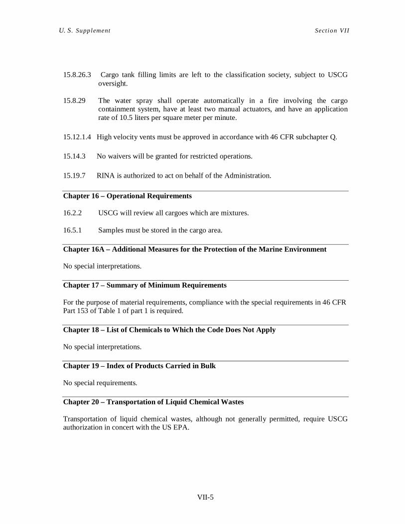
VII-5
U. S. Supplement Sect ion VII
15.8.26.3 Cargo tank filling limits are left to the classification society, subject to USCG
oversight. 15.8.29 The water spray shall operate automatically in a fire involving the cargo
containment system, have at least two manual actuators, and have an application rate of 10.5 liters per square meter per minute.
15.12.1.4 High velocity vents must be approved in accordance with 46 CFR subchapter Q. 15.14.3 No waivers will be granted for restricted operations. 15.19.7 RINA is authorized to act on behalf of the Administration.
Chapter 16 – Operational Requirements
16.2.2 USCG will review all cargoes which are mixtures. 16.5.1 Samples must be stored in the cargo area.
Chapter 16A – Additional Measures for the Protection of the Marine Environment No special interpretations.
Chapter 17 – Summary of Minimum Requirements
For the purpose of material requirements, compliance with the special requirements in 46 CFR Part 153 of Table 1 of part 1 is required.
Chapter 18 – List of Chemicals to Which the Code Does Not Apply No special interpretations.
Chapter 19 – Index of Products Carried in Bulk
No special requirements.
Chapter 20 – Transportation of Liquid Chemical Wastes
Transportation of liquid chemical wastes, although not generally permitted, require USCG authorization in concert with the US EPA.
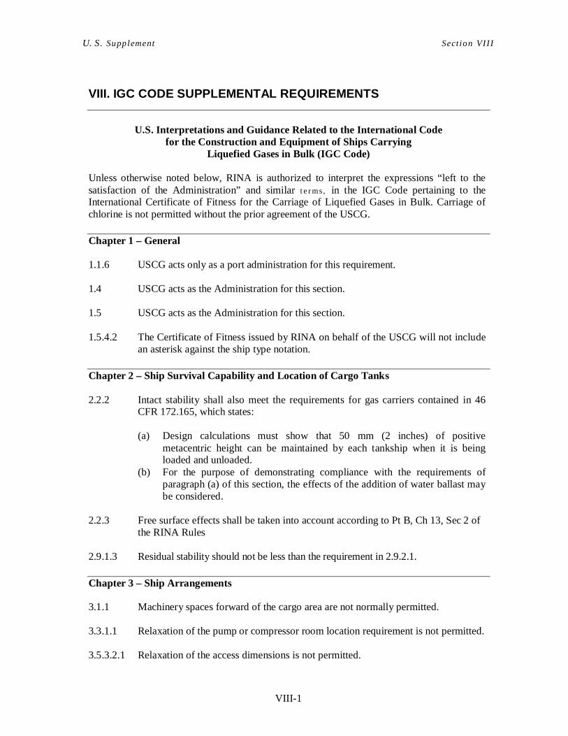
VIII-1
U. S. Supplement Sect ion VII I
VIII. IGC CODE SUPPLEMENTAL REQUIREMENTS
U.S. Interpretations and Guidance Related to the International Code
for the Construction and Equipment of Ships Carrying Liquefied Gases in Bulk (IGC Code)
Unless otherwise noted below, RINA is authorized to interpret the expressions “left to the satisfaction of the Administration” and similar t e r ms, in the IGC Code pertaining to the International Certificate of Fitness for the Carriage of Liquefied Gases in Bulk. Carriage of chlorine is not permitted without the prior agreement of the USCG.
Chapter 1 – General 1.1.6 USCG acts only as a port administration for this requirement. 1.4 USCG acts as the Administration for this section. 1.5 USCG acts as the Administration for this section. 1.5.4.2 The Certificate of Fitness issued by RINA on behalf of the USCG will not include
an asterisk against the ship type notation.
Chapter 2 – Ship Survival Capability and Location of Cargo Tanks 2.2.2 Intact stability shall also meet the requirements for gas carriers contained in 46
CFR 172.165, which states:
(a) Design calculations must show that 50 mm (2 inches) of positive metacentric height can be maintained by each tankship when it is being loaded and unloaded.
(b) For the purpose of demonstrating compliance with the requirements of paragraph (a) of this section, the effects of the addition of water ballast may be considered.
2.2.3 Free surface effects shall be taken into account according to Pt B, Ch 13, Sec 2 of
the RINA Rules 2.9.1.3 Residual stability should not be less than the requirement in 2.9.2.1.
Chapter 3 – Ship Arrangements 3.1.1 Machinery spaces forward of the cargo area are not normally permitted. 3.3.1.1 Relaxation of the pump or compressor room location requirement is not permitted. 3.5.3.2.1 Relaxation of the access dimensions is not permitted.

VIII-2
U. S. Supplement Sect ion VII I
3.8.1.1 Bow and stern unloading is not permitted for toxic products. 3.8.4 Relaxation of this section’s requirements is not permitted.
Chapter 4 – Cargo Containment 4.1 Cargo containment systems not previously accepted by the USCG will require
USCG review and approval. A list of cargo containment systems currently accepted by the USCG may be obtained from Commandant (CG-522).
4.2.2.3 See Note concerning 4.1 4.2.4.2 Recognized standards are RINA Rules. 4.2.4.4 Type C tanks may only be allocated to Type B. 4.2.5.4 Internal insulation tanks shall not have a design vapor pressure greater than 0.7
bar. 4.2.6.4 Higher vapor pressures in port are subject to USCG approval. 4.2.7 Provisions to cover low temperature prevention are covered in Chapter 13. 4.3.2.1 Equivalent calculation procedures must be submitted to USCG. 4.3.4.3 Simplified loading spectra shall not be used. 4.3.4.5 No special consideration shall be given for restricted service. 4.4.1 Integral tanks must meet RINA Rules. 4.4.2.5 RINA Leonardo Hull 2D/3D shall be used for structural analysis, and RINA Rules
will be used for recognized standards. 4.4.4.1 RINA Rules will be used for recognized standards. 4.4.4.2 RINA Rules will be used for recognized standards. 4.4.5.5 Model tests will normally be required. 4.5.1.4 The value of A shall be 4.0 for all materials. 4.5.1.6 For type C tanks, the stress factor “A” must be taken as 4.0, regardless of the
material type. 4.4.6 ASME Boiler and Pressure Vessel Code will be used as the acceptable standard,
except as required otherwise.
4.4.7.2.1 RINA Leonardo Hull 2D/3D will be used for structural analysis.

VIII-3
U. S. Supplement Sect ion VII I
4.4.7.2.3 RINA Rules are the recognized standards 4.4.7.3 See Note on 4.1. 4.5.1.1 RINA Rules are recognized standards. 4.5.1.3 Acceptable stresses are those which agree with RINA Rules. 4.5.1.4 Vessels operating in US waters shall be designed with Stress factors IAW 46 CFR
154 Table 2. 4.5.1.5 As above. 4.5.1.7.2 Special consideration of improved tensile and yield properties must be
demonstrated to the USCG. 4.5.1.10 Unspecified materials must be reviewed by USCG. 4.5.2.1 Corrosion allowances will be required for tanks that are not surrounded by inert gas
or dry air or for corrosive cargoes. USCG will provide the values for these allowances upon request.
4.7.3 Semi-membrane tanks shall have a full secondary barrier. 4.7.7 Either a pressure/vacuum test or a visual test shall be specified. 4.8.1 The longitudinal contiguous hull structure of a vessel having cargo containment
systems with secondary barriers must be designed for a temperature that is colder that the calculated temperature of this hull structure when:
(a) the temperature of the secondary barrier is the design temperature; and (b) for operation anywhere except Alaskan waters, the ambient cold
condition of (A) 5 knots air at -18°C (-0,4°F); and (B) still sea water at 0°C (32°F); or
(c) for operation in Alaskan waters, the ambient cold condition of (A) 5 knots air at -29°C (-20,2°F); and (B) still sea water at – 2°C (28,4°F); or (2) maintained by the heating system under 46 CFR 154.178.
4.8.4.4 In general, hull heating systems are not acceptable. 4.9.1 Recognized standards are RINA Rules, but vessels trading to the U.S. should have
crack arresting steels in way of the deck stringer, shear strake, and turn of the bilge that meet the grades specified in 46 CFR 154.170(b).
4.9.8 Quality control of insulation is delegated, subject to USCG oversight. 4.10.1.2.1 Alternative edge penetrations are generally not permitted. 4.10.1.2.2 The ASME Code is the acceptable standard; other standards require USCG
approval.
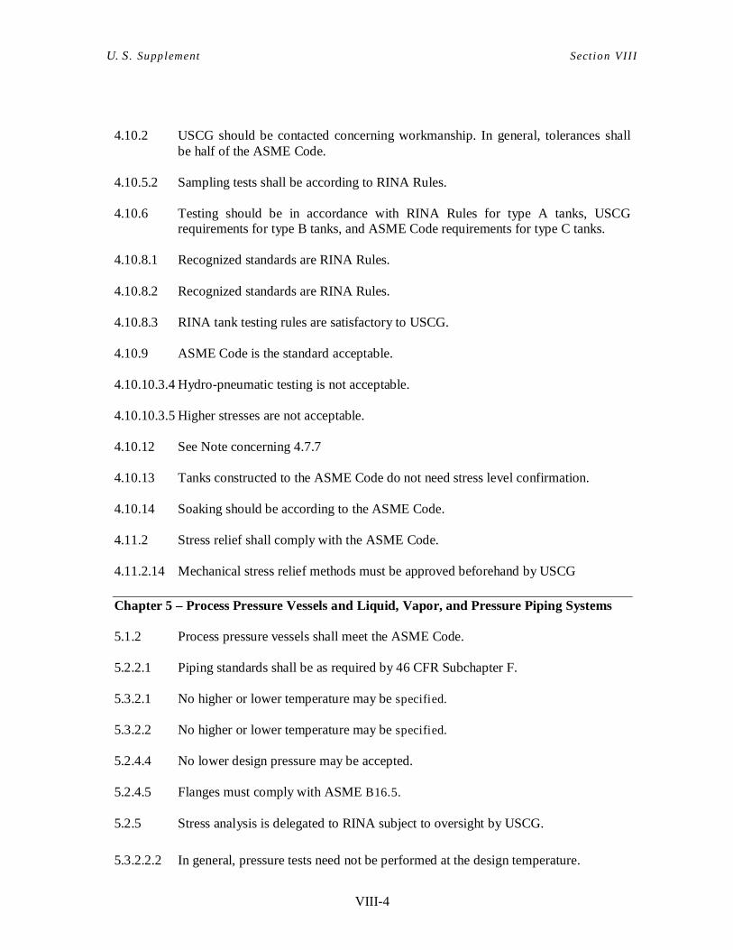
VIII-4
U. S. Supplement Sect ion VII I
4.10.2 USCG should be contacted concerning workmanship. In general, tolerances shall
be half of the ASME Code. 4.10.5.2 Sampling tests shall be according to RINA Rules. 4.10.6 Testing should be in accordance with RINA Rules for type A tanks, USCG
requirements for type B tanks, and ASME Code requirements for type C tanks. 4.10.8.1 Recognized standards are RINA Rules. 4.10.8.2 Recognized standards are RINA Rules. 4.10.8.3 RINA tank testing rules are satisfactory to USCG. 4.10.9 ASME Code is the standard acceptable. 4.10.10.3.4 Hydro-pneumatic testing is not acceptable. 4.10.10.3.5 Higher stresses are not acceptable. 4.10.12 See Note concerning 4.7.7 4.10.13 Tanks constructed to the ASME Code do not need stress level confirmation. 4.10.14 Soaking should be according to the ASME Code. 4.11.2 Stress relief shall comply with the ASME Code. 4.11.2.14 Mechanical stress relief methods must be approved beforehand by USCG
Chapter 5 – Process Pressure Vessels and Liquid, Vapor, and Pressure Piping Systems 5.1.2 Process pressure vessels shall meet the ASME Code.
5.2.2.1 Piping standards shall be as required by 46 CFR Subchapter F.
5.3.2.1 No higher or lower temperature may be specified.
5.3.2.2 No higher or lower temperature may be specified.
5.2.4.4 No lower design pressure may be accepted.
5.2.4.5 Flanges must comply with ASME B16.5.
5.2.5 Stress analysis is delegated to RINA subject to oversight by USCG.
5.3.2.2.2 In general, pressure tests need not be performed at the design temperature.
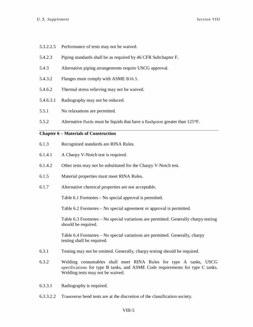
VIII-5
U. S. Supplement Sect ion VII I
5.3.2.2.5 Performance of tests may not be waived. 5.4.2.3 Piping standards shall be as required by 46 CFR Subchapter F. 5.4.3 Alternative piping arrangements require USCG approval. 5.4.3.2 Flanges must comply with ASME B16.5. 5.4.6.2 Thermal stress relieving may not be waived. 5.4.6.3.1 Radiography may not be reduced. 5.5.1 No relaxations are permitted. 5.5.2 Alternative fluids must be liquids that have a flashpoint greater than 125°F.
Chapter 6 – Materials of Construction 6.1.3 Recognized standards are RINA Rules. 6.1.4.1 A Charpy V-Notch test is required. 6.1.4.2 Other tests may not be substituted for the Charpy V-Notch test. 6.1.5 Material properties must meet RINA Rules. 6.1.7 Alternative chemical properties are not acceptable.
Table 6.1 Footnotes – No special approval is permitted.
Table 6.2 Footnotes – No special agreement or approval is permitted. Table 6.3 Footnotes – No special variations are permitted. Generally charpy testing should be required.
Table 6.4 Footnotes – No special variations are permitted. Generally, charpy testing shall be required.
6.3.1 Testing may not be omitted. Generally, charpy testing should be required. 6.3.2 Welding consumables shall meet RINA Rules for type A tanks, USCG
specifications for type B tanks, and ASME Code requirements for type C tanks. Welding tests may not be waived.
6.3.3.1 Radiography is required. 6.3.3.2.2 Transverse bend tests are at the discretion of the classification society.
VIII-6
U. S. Supplement Sect ion VII I
6.3.3.2.4 Requirements for these tests are left to the discretion of the classification society. 6.3.4.2 No special agreement is permitted. 6.3.4.3 Recognized standards for this section will be individually reviewed. 6.3.5 Test requirements should be in accordance with 6.3.4. 6.3.6.1 A reduction in test for secondary barrier is not acceptable. 6.3.6.2.2 USCG will consider alternatives to the energy requirements, on a case-by-case
basis. 6.3.6.3 USCG will consider alternatives to the energy requirements, on a case-by-case
basis. 6.3.6.4 Integral and membrane tests must be inspected according to USCG approved
standards available from the manufacturer. 6.3.7.1.2 Tank examination will be as approved by USCG for the tank designed. 6.3.7.1.3 RINA Rules shall be the recognized standards, except that for membrane tanks, the
USCG accepted manufacturer’s procedures shall be used. 6.3.7.3 See Note for 6.3.7.1.3.
Chapter 7 – Cargo Pressure/Temperature Control 7.1 Refrigeration systems shall meet 46 CFR 154.702. Stand-by unit is required.
Unless refrigeration system is installed, cargoes with a vapor pressure exceeding the MARVS at 45°C are not authorized in US Waters
7.1.1 Design of cargo pressure and temperature control must contain cargo for 21 days,
and cargo venting cannot be used to control tank pressure while in U.S. ports. 7.1.2 Special design ambient temperatures apply for Alaskan waters, as given in 46 CFR
154.176.
Chapter 8 – Cargo Tank Vent Systems 8.2.2 Pressure/vacuum relief is delegated to RINA, subject to USCG oversight. 8.2.5 RINA is the acceptable authority. 8.2.7 Changing of relief valve settings will be overseen by a surveyor of RINA.
8.2.10 No relaxation of this requirement is accepted for ships less than 90 m.
VIII-7
U. S. Supplement Sect ion VII I
8.4.2.3 Other vacuum relief systems must be handled under the conditions of 1.4. 8.5.2 Approval for F=0.5 is delegated to the RINA, subject to USCG oversight.
Chapter 9 – Environmental Control 9.5.2 A check valve is an acceptable means.
Chapter 10 – Electrical Installations The National Electric Code, NFPA 70, Art. 500-504, shall be applied. 10.1 The RINA Rules for Classification of Ships, Pt.E, Ch.8, Sec.10 which is in line
with IEC 60092-502 apply Chapter 11 – Fire Protection and Fire Extinction 11.3.4 When the fire main pumps are used to supply the water spray system, the fire
main must still be able to operate at full capacity. 11.4.3 RINA is delegated to accept standards for ships with a capacity less than 1,000
cubic meters (35314 cubic feet). 11.4.4 Suitable alternatives will be considered according to 1.4. 11.5.2 Relaxations are not permitted for ships carrying a restricted number of cargoes.
Chapter 12 – Mechanical Ventilation in the Cargo Area 12.1.5 Positive pressure ventilation is not acceptable.
Chapter 13 – Instrumentation (Gauging, Gas Detection) 13.1.4 Testing intervals and procedures are delegated to RINA, subject to USCG
oversight. Vessels in U.S. ports should be able to demonstrate that the instruments function, and in the case of gas detection, that they are properly calibrated.
13.2.4 Gauge glasses need USCG approval, but are generally not acceptable. 13.3.1 USCG should be contacted in the case that it is the port authori ty. Sensors
required for automatic closing of the shut-off valve for overflow controls as specified by 13.3.1 and the liquid level as specified by 13.2.1 must be independent of each other, however, the sensors may send signals to the same actuator.
13.5.4 Temperature sensors should be at the bottom of the tank and near the top of the
VIII-8
U. S. Supplement Sect ion VII I
tank, below the maximum filling level. 13.6.1 Gas detection is delegated to RINA, subject to USCG oversight. 13.6.11 Other limits are not acceptable. 13.6.13 Portable gas detectors should meet the thresholds specified by OSHA.
Chapter 14 – Personnel Protection 14.2.4 The provisions of this paragraph are not acceptable. 14.4.5 This requirement is delegated to RINA, subject to USCG oversight.
Chapter 15 – Filling Limits for Cargo Tanks 15.1.3 Higher filling limits are permitted IAW Resolution A.829(19). 15.2 The approval of this list is delegated without restriction.
Chapter 16 – Use of Cargo as Fuel 16.5.2 This requirement is delegated to RINA, subject to USCG oversight. 16.5.6 This requirement is delegated to RINA, subject to USCG oversight. 16.6 This requirement is delegated to RINA, subject to USCG oversight.
Chapter 17 – Special Requirements 17.1 Carbon Dioxide is not permitted in US Waters. 17.14 Chlorine may not be carried in U.S. waters. 17.18.3 Other compositions require USCG approval. 17.19 Nitrogen cargo carriage requires special USCG approval.
Methyl acetylene propadiene mixtures (MAPP gas) shall be carried only in one of the two compositions specified in the applicable Gas Code.
17.20 Propylene oxide may be authorized for carriage subject to the following special restrictions:
(a) Classification society certification that the required cargo piping separation
VIII-9
U. S. Supplement Sect ion VII I
has been achieved must be on board the vessel and available to Coast Guard boarding personnel.
(b) All gaskets which may contact propylene oxide liquid or vapor must be constructed from spirally wound stainless steel with a filler of Teflon or similar fluorinated polymer.
(c) Neoprene, natural rubber, asbestos mixed with other materials, and materials containing oxides of magnesium (such as mineral wools) may not be used for packing, insulation and similar items in the propylene oxide containment system and piping.
The following requirements apply to the carriage of ethylene oxide/propylene oxide mixtures (containing a maximum of 30% ethylene oxide):
(a) The requirements for propylene oxide given above must be followed.
(b) When this cargo is carried without refrigeration the cargo tank relief valve setting shall not be less than 120 kPa gauge (17 psig).
17.20.3.1 Only steel or stainless steel are acceptable. 17.20.13.2 The approval of handling plans is delegated to RINA. 17.20.14 The approval of filling limits is delegated to RINA. 17.21 Operational requirements for the carriage of Vinyl Chloride:
Fixed or portable instruments shall be used to continuously monitor for vinyl chloride vapor leaks during vinyl chloride transfer operations. The method of monitoring and measurement shall have an accuracy (with a confidence level of 95 percent) of not less than ± 50 % from 0.25 through 0.5 ppm, ± 35% from over 0.5 ppm through 1.0 ppm, and ± 25% over 1.0 ppm;
Cargo transfer operation is discontinued or corrective action is initiated by the person in charge to minimize exposure to personnel whenever a vinyl chloride vapor concentration in excess of 1 ppm is detected. If the vinyl chloride vapor concentration exceeds 5 ppm for over 15 minutes, action to reduce the leak can be continued only if the respiratory protection requirements of 29 CFR 1910.1017 are met by all personnel in the area of the leak;
Those portions of cargo lines which will be open to the atmosphere after piping is disconnected are free of vinyl chloride liquid and the vinyl chloride vapor concentration in the area of the cargo piping disconnect points is not greater than 5 ppm; Any restricted gauge fitted on a tank containing vinyl chloride is locked or sealed so that it cannot be used and a restricted gauge is not used as a check on the
VIII-10
U. S. Supplement Sect ion VII I
required closed gauge, nor as a means of sampling;
The words “CANCER-SUSPECT AGENT” are added to the warning signs required by 46 CFR 154.1830, and signs bearing the legend: “CANCERSUSPECT AGENT IN THIS AREA, PROTECTIVE EQUIPMENT REQUIRED, AUTHORIZED PERSONNEL ONLY” are posted whenever hazardous operations, such as tank cleaning, are in progress;
A vessel undergoing cargo transfer operations be designated a “regulated area” having access limited to authorized persons and requiring a daily roster of authorized persons who may board, and;
Employees engaged in hazardous operations, such as tank cleaning, be required to wear and use respiratory protection in accordance with the provisions of 29 CFR 1910.1017 and protective garments, provided clean and dry for each use, to prevent skin contact with liquid vinyl chloride.
Chapter 18 – Operating Requirements No special requirements.
Chapter 19 – Summary of Minimum Requirements No special requirements.
IX-1
U. S. Supplement Sect ion IX
IX. REQUIREMENTS FOR OFFSHORE SUPPLY VESSELS (OSV’s) CERTIFICATED UNDER SUBCHAPTER L, EXCEPT LIFTBOATS
Scope: This section specifies additional or different requirements that apply to Subchapter L
OSV’s (except liftboats) certificated under Subchapter L enrolled or to be enrolled in the Alternate Compliance Program.
Note 1: In addition to what indicated in this Section, Any OSV that operates seaward of the boundary line and that is certified to carry hazardous or NLS cargoes must also comply with CG-522 Policy Letter 09-01, “GUIDANCE ON IMPLEMENTATION OF IMO RESOLUTION A.673(16) FOR U.S. OFFSHORE SUPPLY VESSELS” (as amended).
Note 2: Subchapter L “Liftboats” is not included in this Section
Cite: A-1 Stability In addition to requirements of RINA Rules Pt.E, Ch.15, Sec.2, (3) for intact stability, OSV’s are also to comply with the subdivision and damage stability requirements contained in either (a) IMO Res. MSC.235(82), section 3, or (b) 46 CFR 174.195, 174.205, and 174.207.
Cite: A-2 Carriage of Flammable or Combustible Liquid Cargoes in Bulk
Note: Provisions for the carriage of noxious liquid substances in bulk as defined in
MARPOL Annex II may be augmented by appropriate measures promulgated by the Commandant.
An OSV may carry the following in integral tanks: (a) Grade-D combustible liquids (having an open cup flashpoint below 65,5 degrees C
(150 degrees F) and above 26,6 degrees C (80 degrees F)), in quantities not to exceed 20 percent of the vessel’s deadweight, except that the vessel may carry drilling fluids and excess fuel oil, Grade-E (combustible liquid having a flashpoint of 65,5 degrees C (150 degrees F) and above)) as well as Grade-D, without limit.
(b) Grade-E combustible liquids (having an open cup flashpoint of 65,5 degrees C (150
degrees F) or above), in quantities not to exceed 20 percent of the vessel’s deadweight, except that the vessel may carry drilling fluids and excess fuel oil, Grade-D as well as Grade-E, without limit.
(c) An OSV may carry the following in fixed independent tanks on deck: Grade-B
(flammable liquids having an open cup flashpoint below 26,6 degrees C (80 degrees F) and having a Reid vapor pressure under 14 pounds and over 8-1/2 pounds) and
IX-2
U. S. Supplement Sect ion IX
lower-grade flammable and combustible liquids, in quantities not to exceed 20 percent of the vessel’s deadweight.
(d) An OSV may carry hazardous materials in approved portable tanks. A portable tank
may be filled or discharged aboard the vessel if authorized by an endorsement on the vessel’s Certificate of Inspection.
Cite: A-3 Carriage of Noxious Liquid Substances in Bulk Note: Provisions for the carriage of noxious liquid substances in bulk as defined in
MARPOL Annex II may be augmented by appropriate measures promulgated by the Commandant.
(a) Except as provided below, no OSV may carry a noxious liquid substances (NLS) in
bulk without the approval of the Commandant. (b) An OSV may carry NLS, in integral and fixed independent tanks, in quantities not to
exceed 20 percent of the vessel’s deadweight. (c) Each OSV carrying NLS’s in bulk in integral tanks or fixed independent tanks must
have: a Certificate of Inspection or NLS Certificate endorsed with names of NLS cargoes; and a Cargo Record Book that complies with MARPOL Annex II requirements.
(d) An OSV that does not meet the equipment requirements may not discharge NLS residues into the sea.
(e) Each OSV that discharges NLS residues into the sea must meet the equipment requirements of regulations contained in MARPOL Annex II Chapter 5.
Cite: A-4 Cranes Cargo Gear is to be certified in accordance with the “RINA Rules for Loading and Unloading Arrangements and for other Lifting Appliances on Board Ships, effective from 1 January 2009”, as applicable for the type of cargo gear being provided. As an alternative, evidence of approval issued by recognized bodies in accordance with requirements deemed equivalent by RINA to those contained in the above mentioned Rules may be submitted.
Cite: A-5 Carriage of Offshore Workers Offshore worker means an individual carried aboard an OSV and employed in a phase of exploration, exploitation, or production of offshore mineral or energy resources served by the vessel; but it does not include the master or a member of the crew engaged in the business of the vessel, who has contributed no consideration for carriage aboard and is paid for services aboard. In no case will the number of offshore workers authorized for carriage exceed 36.
IX-3
U. S. Supplement Sect ion IX
No more than 12 offshore workers may be carried aboard an OSV when on an international voyage, unless the vessel holds a valid passenger-ship-safety certificate issued in compliance with the International Convention for the Safety of Life at Sea, 1974, as amended.
Cite: A-6 Means of Escape (a) A vertical ladder ending at a deck scuttle may be the second means of escape if the:
(1) primary means of escape is a stairway or passageway; (2) installation of another stairway or passageway is impracticable; (3) scuttle is located where stowed deck cargo could not interfere; (4) scuttle is fitted with a quick-acting release, and with a hold-back device to hold
it open; and (5) scuttle meets the requirements for location, strength, and height of coaming in
the International Convention on Load Lines. (b) Each vertical ladder must:
(1) Have rungs that are: (i) at least 410 millimeters (16 inches) long; (ii) at most 300 millimeters (12 inches) apart, uniform for the length of the
ladder; and (iii) at least 180 millimeters (7 inches) from the nearest permanent object in
back of the ladder;Have at least 115 millimeters (4-1/2 inches) of clearance above each rung;
(2) Be made of incombustible materials; and (3) Have an angle of inclination with the horizontal, greater than 70 degrees but not
more than 90 degrees. (c) No means may be provided for locking any interior door giving access to either of the
two required means of escape, except that a crash door or locking-device, capable of being easily forced in an emergency, may be employed if a permanent and conspicuous notice to this effect is attached to both sides of the door. A means may be provided for locking an exterior door to a deckhouse if the door is:
(1) Locked only by a key under the control of one of the OSV’s officers; and (2) Always operable from the inside.
Cite: A-7 Accommodations for Crew Members and Offshore Workers
The following requirements apply to accommodations for offshore workers on each vessel: (a) Each offshore worker aboard must be provided with adequate fixed seating. The
width of each seat should be at least 460 millimeters (18 inches). The spacing of fixed seating must be sufficient to allow ready escape in case of fire or other emergency. The following are minimal requirements:
IX-4
U. S. Supplement Sect ion IX
(i) aisles 4.6 meters (15 feet) in length or less must not be less than 610 millimeters
(24 inches) wide. (ii) aisles more than 4.6 meters (15 feet) in length must not be less than 760
millimeters (30 inches) wide. (iii) where the seating is in rows, the distance from seat front to seat front must not
be less than 760 millimeters (30 inches). (b) If the intended operation of a vessel is to carry offshore workers aboard for more than
24 hours, quarters for them must be provided. Each stateroom for use by them must:
(i) berth no more than six workers; (ii) have clear headroom of at least 1.9 meters (6 feet, 3 inches); and (iii) contain at least 1.9 square meters (20 square feet) of deck and at least 4 cubic
meters (140 cubic feet) of space for each worker accommodated. The presence in a stateroom of equipment for use by the occupants does not diminish the area or volume of the room.
(c) There must be at least one toilet, one washbasin, and one shower or bathtub for every
eight or fewer offshore workers who do not occupy a stateroom to which a private or a semiprivate facility is attached.
OSV’s are not required to be outfitted with a Hospital Space required by Section III Cite B.8 of the U.S. Supplement.
Cite: A-8 Keel Cooler Installations Fillet welds may be used in the attachment of channels and half-round pipe sections to the bottom of the vessel.
Cite: A-9 Liquid-Mud Systems System to be in compliance with 46 CFR 128.450.
Cite: A-10 Dual-Voltage Generators If a dual-voltage generator is installed on an OSV the neutral of the dual-voltage system must be solidly grounded at the switchboard’s neutral bus and be accessible for checking the insulation resistance of the generator. Resistance or impedance grounding in lieu of solid grounding must be approved by the Coast Guard Marine Safety Center.
Cite: A-10a Grounded Distribution System If a grounded distribution system is provided, there must be only one connection to ground, regardless of the number of power sources.
IX-5
U. S. Supplement Sect ion IX
Cite: A-11 Automation of Unattended Machinery Spaces OSV’s intended to operate with periodically unattended machinery spaces are to comply with the class requirements for class notation ACCU as well as other applicable requirements of this Supplement.
Cite: A-15 Fire Stations Each outlet at a fire hydrant must be at least 38 millimeters (1 1/2 inch) in diameter and, to minimize the possibility of kinking, must be fitted so that no hose leads upward from it. Each fire hydrant must have a fire hose 15.2 meters (50 feet) in length, with a minimum diameter of 38 millimeters (1 1/2 inches), connected to an outlet, for use at any time. A suitable hose rack or other device must be provided for each fire hose. Each rack on a weather deck must be placed so as to protect its hose from heavy weather.
Cite: A-16 Fire Monitors When a fire monitor is connected to the fire main system, it must be led from the discharge manifold of the fire pump. Each fire monitor must be fitted with a shut-off valve at the monitor and at the connection to the fire pump discharge manifold.
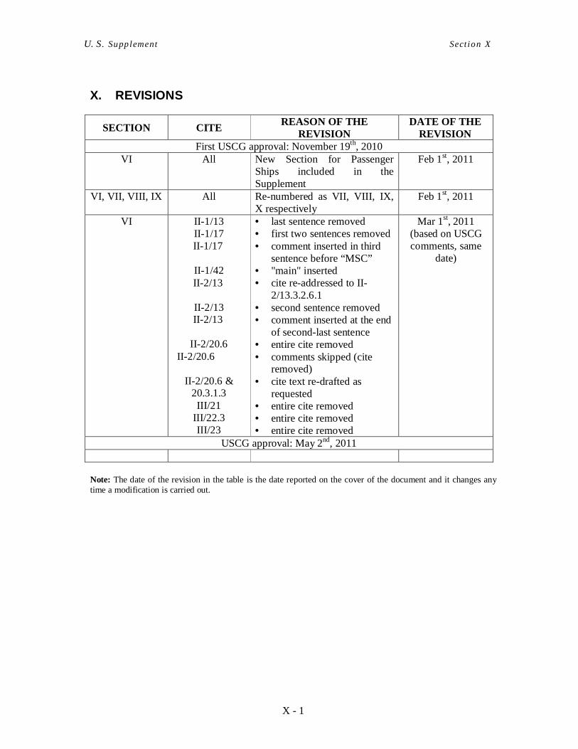
X - 1
U. S. Supplement Sect ion X
X. REVISIONS
SECTION CITE REASON OF THE REVISION
DATE OF THE REVISION
First USCG approval: November 19th, 2010 VI All New Section for Passenger
Ships included in the Supplement
Feb 1st, 2011
VI, VII, VIII, IX All Re-numbered as VII, VIII, IX, X respectively
Feb 1st, 2011
VI II-1/13 II-1/17 II-1/17
II-1/42 II-2/13
II-2/13 II-2/13
II-2/20.6
II-2/20.6
II-2/20.6 & 20.3.1.3 III/21
III/22.3 III/23
• last sentence removed • first two sentences removed • comment inserted in third
sentence before “MSC” • "main" inserted • cite re-addressed to II-
2/13.3.2.6.1 • second sentence removed • comment inserted at the end
of second-last sentence • entire cite removed • comments skipped (cite
removed) • cite text re-drafted as
requested • entire cite removed • entire cite removed • entire cite removed
Mar 1st, 2011 (based on USCG comments, same
date)
USCG approval: May 2nd, 2011
Note: The date of the revision in the table is the date reported on the cover of the document and it changes any time a modification is carried out.