Rigid Body Equilibrium - University of Memphis Body Diagrams.pdf · 3 5 Free Body Diagrams...
34
1 Rigid Body Equilibrium Free Body Diagrams and the Equations of Equilibrium A small boy swallowed some coins and was taken to a hospital. When his grandmother telephoned to ask how he was a nurse said 'No change yet'. Wednesday, October 3, 2012 Free Body Diagrams 2 Objectives Expand the number of support conditions used in equilibrium problems Expand the types of equilibrium problems to include new support conditions
Transcript of Rigid Body Equilibrium - University of Memphis Body Diagrams.pdf · 3 5 Free Body Diagrams...
1
Rigid Body Equilibrium Free Body Diagrams and the
Equations of Equilibrium
A small boy swallowed some coins and was taken to a hospital. When his grandmother telephoned to ask how he was a nurse said
'No change yet'.
Wednesday, October 3, 2012 Free Body Diagrams 2
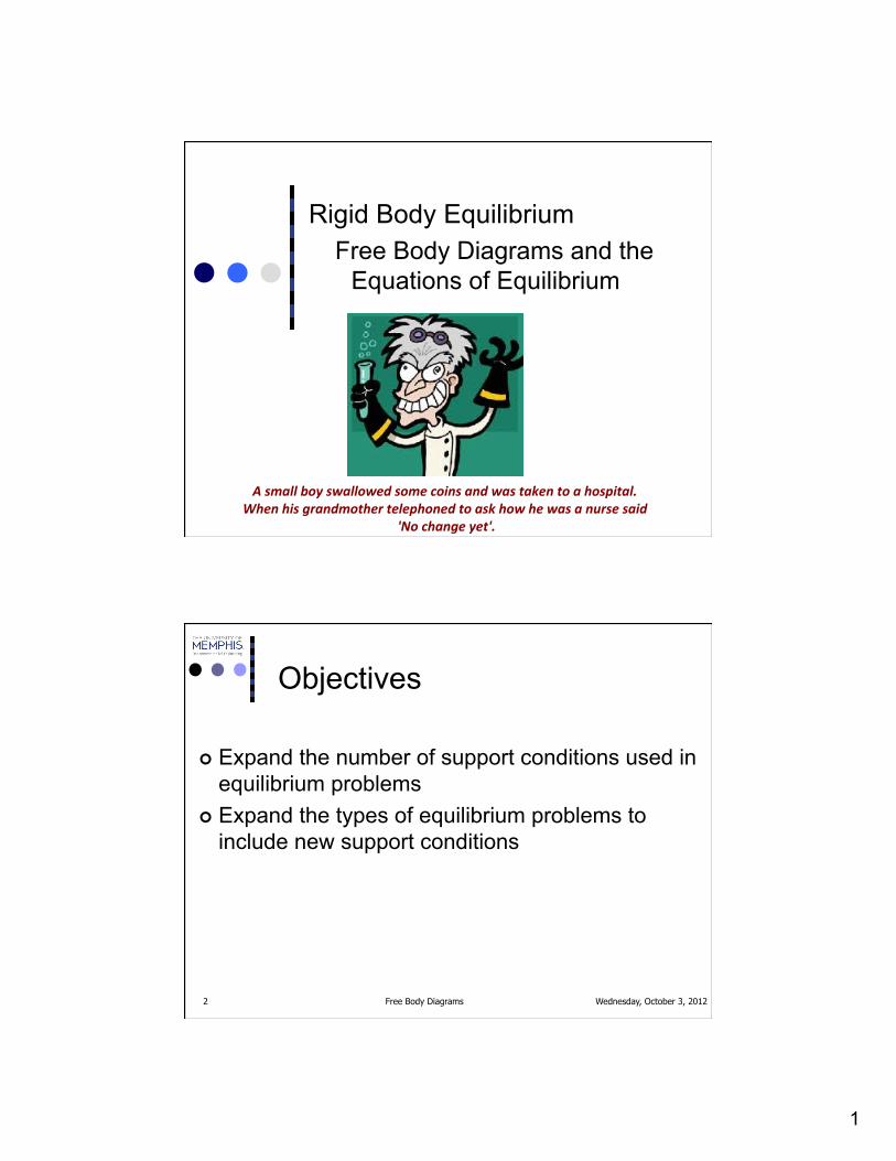
Objectives
¢ Expand the number of support conditions used in equilibrium problems
¢ Expand the types of equilibrium problems to include new support conditions
2
Wednesday, October 3, 2012 Free Body Diagrams 3
Tools
¢ Algebra ¢ Trigonometry ¢ Force components ¢ Unit Vectors ¢ Moments
Wednesday, October 3, 2012 Free Body Diagrams 4
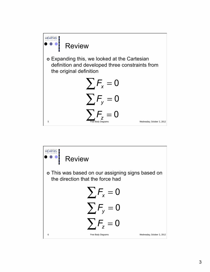
Review
¢ When we looked at equilibrium earlier, we used a single condition for equilibrium
F = 0∑
3
Wednesday, October 3, 2012 Free Body Diagrams 5
Review
¢ Expanding this, we looked at the Cartesian definition and developed three constraints from the original definition
=
=
=
∑∑∑
0
0
0
x
y
z
F
F
F
Wednesday, October 3, 2012 Free Body Diagrams 6
Review
¢ This was based on our assigning signs based on the direction that the force had
=
=
=
∑∑∑
0
0
0
x
y
z
F
F
F

4
Wednesday, October 3, 2012 Free Body Diagrams 7
Review
¢ If we used vector notation we knew to set the coefficients of each of the components of the summation vector equal to 0
=
=
=
∑∑∑
0
0
0
x
y
z
F
F
F
Wednesday, October 3, 2012 Free Body Diagrams 8
Equilibrium Expanded
¢ All of the problems that we addressed had one thing in common, the line of action of all the forces intersected at a point
=
=
=
∑∑∑
0
0
0
x
y
z
F
F
F

5
Wednesday, October 3, 2012 Free Body Diagrams 9
Equilibrium Expanded
¢ When we remove that restriction, we can add a second condition for equilibrium
M
= 0∑F= 0∑
Wednesday, October 3, 2012 Free Body Diagrams 10
Equilibrium Expanded
¢ The sum of the forces acting on a system must be equal to 0
¢ The sum of the moments generated by the forces acting on the system as well as any applied moments must be equal to 0 at any point taken as a moment center
M
= 0∑F= 0∑

6
Wednesday, October 3, 2012 Free Body Diagrams 11
Equilibrium Expanded
¢ The sum of the forces acting on a system must be equal to 0
¢ The sum of the moments generated by the forces acting on the system as well as any applied moments must be equal to 0 at any point taken as a moment center
M
= 0∑F= 0∑
BOTH OF THESE CONDITIONS MUST BE SATISFIED FOR A SYSTEM TO BE IN
EQUILIBRIUM.
Wednesday, October 3, 2012 Free Body Diagrams 12
Equilibrium Expanded
¢ In two-dimensional space, moments are either into the plane (negative sign) or out of the plane (positive sign) so a scalar interpretation of our equilibrium conditions would be
M
= 0∑F= 0∑
=
=
=
∑∑∑
0
0
0
x
y
F
F
M

7
Wednesday, October 3, 2012 Free Body Diagrams 13
Equilibrium Expanded
¢ In two-dimensional space, moments are either into the plane (negative sign) or out of the plane (positive sign) so a scalar interpretation of our equilibrium conditions would be
=
=
∑∑
ur
ur0
0
M
F
=
=
=
∑∑∑
0
0
0
x
y
F
F
M
WE HAVE THREE EQUATIONS, THEREFORE WE CAN ONLY SOLVE FOR THREE UNKNOWNS USING
THE EQUATIONS OF EQUILIBRIUM ONLY
Wednesday, October 3, 2012 Free Body Diagrams 14
Equilibrium Expanded
¢ Remember, CW moments are negative in this scalar system, CCW moments are positive
=
=
=
∑∑∑
0
0
0
x
y
F
F
M

8
Wednesday, October 3, 2012 Free Body Diagrams 15
Equilibrium Expanded
¢ Before we get to the analysis of problems, we need to review the rules for generating Free Body Diagrams
¢ No matter how good your math is, if you had the wrong Free Body Diagram (FBD) you won’t solve the problem correctly
Wednesday, October 3, 2012 Free Body Diagrams 16
Free Body Diagrams
¢ The FBD is a system isolation that allows us to solve for actions and reactions acting within the system
¢ We choose some element or part of the system and disconnect it from everything that it is connected to
9
Wednesday, October 3, 2012 Free Body Diagrams 17
Free Body Diagrams
¢ Every time that we disconnect something from our system, we replace it with the reaction which could be generated by this type of connection
Wednesday, October 3, 2012 Free Body Diagrams 18
Free Body Diagrams
¢ We used two connections so far l Ropes l Springs
¢ And one external force generator l Gravity or weight

10
Wednesday, October 3, 2012 Free Body Diagrams 19
Free Body Diagrams
¢ Ropes always pull on what they are connected to and the pull always is along the line of the rope itself
¢ Springs can either push or pull on what they are connected to
¢ The force that they generate always has a line of action that lies along the spring itself
Wednesday, October 3, 2012 Free Body Diagrams 20
Free Body Diagrams
¢ We also considered the effect of gravity on a system
¢ Gravity always pulls down (toward the center of the earth)
¢ If the weight or the mass of a system isn’t given, it can be considered as negligible to the rest of the system

11
Wednesday, October 3, 2012 Free Body Diagrams 21
New Support Conditions
¢ We now need to expand our number of support conditions to include some of the more common supports
¢ Almost all physical conditions can be modeled using one or more of these supports
Wednesday, October 3, 2012 Free Body Diagrams 22
New Support Conditions
¢ Most of the support conditions can be figured out using common sense if you will just think about encountering them in “real” life

12
Wednesday, October 3, 2012 Free Body Diagrams 23
New Support Conditions Smooth Surface Contact
¢ If you were to push on a hard smooth surface, think about how it would push back
Hard Smooth Surface
Wednesday, October 3, 2012 Free Body Diagrams 24
New Support Conditions Smooth Surface Contact
¢ We have a rod/stick/something resting on a smooth surface (smooth is important here)
Hard Smooth Surface
13
Wednesday, October 3, 2012 Free Body Diagrams 25
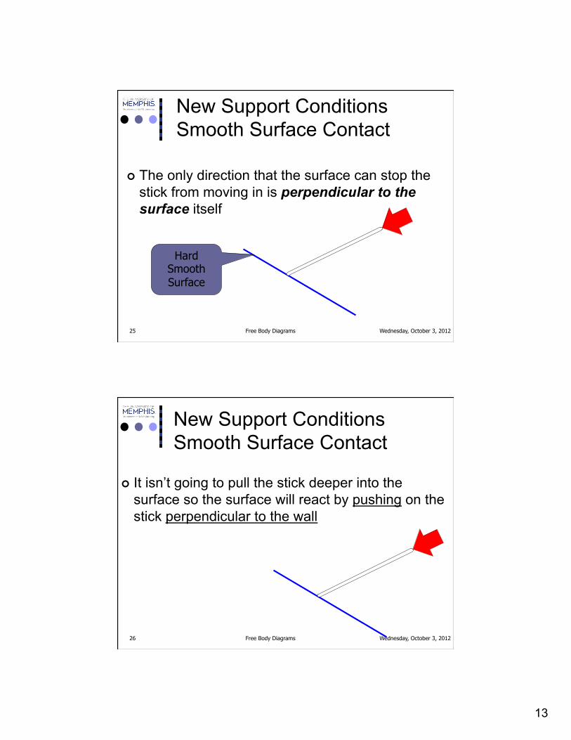
New Support Conditions Smooth Surface Contact
¢ The only direction that the surface can stop the stick from moving in is perpendicular to the surface itself
Hard Smooth Surface
Wednesday, October 3, 2012 Free Body Diagrams 26
New Support Conditions Smooth Surface Contact
¢ It isn’t going to pull the stick deeper into the surface so the surface will react by pushing on the stick perpendicular to the wall

14
Wednesday, October 3, 2012 Free Body Diagrams 27
New Support Conditions Smooth Surface Contact
¢ Remember that the action of the surface is a reaction to the action of the stick
¢ If the stick doesn’t push, the wall has nothing to push back against
Wednesday, October 3, 2012 Free Body Diagrams 28
New Support Conditions Smooth Surface Contact
¢ Two important factors of the reaction
l Directed away from the surface l Normal to the surface
15
Wednesday, October 3, 2012 Free Body Diagrams 29
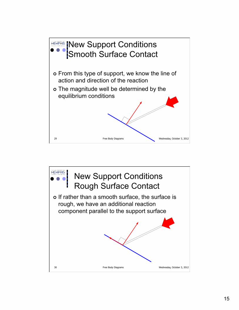
New Support Conditions Smooth Surface Contact
¢ From this type of support, we know the line of action and direction of the reaction
¢ The magnitude well be determined by the equilibrium conditions
Wednesday, October 3, 2012 Free Body Diagrams 30
New Support Conditions Rough Surface Contact
¢ If rather than a smooth surface, the surface is rough, we have an additional reaction component parallel to the support surface

16
Wednesday, October 3, 2012 Free Body Diagrams 31
New Support Conditions Rough Surface Contact
¢ The direction of the parallel component is determined by the direction of impending motion of the system touching the surface
Wednesday, October 3, 2012 Free Body Diagrams 32
New Support Conditions Rough Surface Contact
¢ For a while we will only be concerned with smooth surfaces

17
Wednesday, October 3, 2012 Free Body Diagrams 33
New Support Conditions Pin Connection
¢ The next type of connection is the pin or the smooth pin or hinge
¢ One way to think of this is to drive a nail through a ruler partway into a table top
Wednesday, October 3, 2012 Free Body Diagrams 34
New Support Conditions Pin Connection
¢ If we looked down on our handiwork and tried to move the ruler in the plane of the table top we couldn’t move it right or left or we couldn’t move it up and down and because we are in a two-dimensional system, we couldn’t move it toward us or away from us
18
Wednesday, October 3, 2012 Free Body Diagrams 35
New Support Conditions Pin Connection
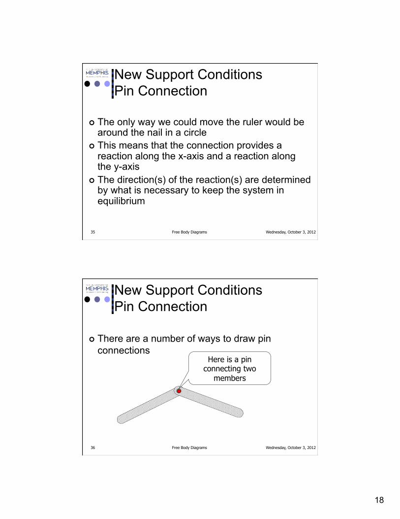
¢ The only way we could move the ruler would be around the nail in a circle
¢ This means that the connection provides a reaction along the x-axis and a reaction along the y-axis
¢ The direction(s) of the reaction(s) are determined by what is necessary to keep the system in equilibrium
Wednesday, October 3, 2012 Free Body Diagrams 36
New Support Conditions Pin Connection
¢ There are a number of ways to draw pin connections
Here is a pin connecting two
members
19
Wednesday, October 3, 2012 Free Body Diagrams 37
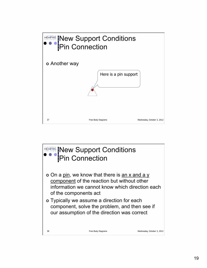
New Support Conditions Pin Connection
¢ Another way
Here is a pin support
Wednesday, October 3, 2012 Free Body Diagrams 38
New Support Conditions Pin Connection
¢ On a pin, we know that there is an x and a y component of the reaction but without other information we cannot know which direction each of the components act
¢ Typically we assume a direction for each component, solve the problem, and then see if our assumption of the direction was correct

20
Wednesday, October 3, 2012 Free Body Diagrams 39
New Support Conditions Pin Connection
¢ For example, if we had the rod that we had earlier but this time we have a weight on the middle of the rod and support the top end with a pin
WEIGHT
Wednesday, October 3, 2012 Free Body Diagrams 40
New Support Conditions Pin Connection
¢ If we select the rod as our system, we won’t have to worry about what the surface or the pin support are connected to
¢ We isolate our system of concern
WEIGHT

21
Wednesday, October 3, 2012 Free Body Diagrams 41
New Support Conditions Pin Connection
¢ We begin by removing elements that are in contact with our system
¢ First we will remove the smooth surface and replace it with its reaction, Fs
WEIGHT
FS
Wednesday, October 3, 2012 Free Body Diagrams 42
New Support Conditions Pin Connection
¢ We can then replace the weight by a force equal to the weight on the same line of action as its connection
FS
W

22
Wednesday, October 3, 2012 Free Body Diagrams 43
New Support Conditions Pin Connection
¢ Finally we can remove the pin connection at the right end of the beam and replace it by an x and a y reaction component
FS
W
FPYFPX
Wednesday, October 3, 2012 Free Body Diagrams 44
New Support Conditions Pin Connection
¢ The notation is clumsy here, we will try to be more precise and work better at this later
FS
W
FPYFPX

23
Wednesday, October 3, 2012 Free Body Diagrams 45
New Support Conditions Pin Connection
¢ Since we didn’t know the line of action of the reaction at the pin, we assumed directions for the components
¢ Is doesn’t matter which way you make your assumption
FS
W
FPYFPX
Wednesday, October 3, 2012 Free Body Diagrams 46
New Support Conditions Roller or Rocker
¢ You can think of this as being supported on ball bearings
¢ The only thing that they can prevent you from doing is going through the surface they are on, almost like the support of a smooth surface
24
Wednesday, October 3, 2012 Free Body Diagrams 47
New Support Conditions Roller or Rocker
¢ Like a smooth surface support, they prevent you from going into the surface on which they are placed
Wednesday, October 3, 2012 Free Body Diagrams 48
New Support Conditions Roller or Rocker
¢ There are quite a few ways that you will see them drawn
¢ The problem itself may state what type of support is at each point
¢ Be sure to look carefully at the support conditions

25
Wednesday, October 3, 2012 Free Body Diagrams 49
New Support Conditions Roller or Rocker
¢ Two very common ways are
Wednesday, October 3, 2012 Free Body Diagrams 50
New Support Conditions Roller or Rocker
¢ The first one looks suspiciously like a pin connection but with the addition of the wheels/ball bearings beneath the support, the only reaction that it can provide is upwards (normal to the surface the balls are resting on)
26
Wednesday, October 3, 2012 Free Body Diagrams 51
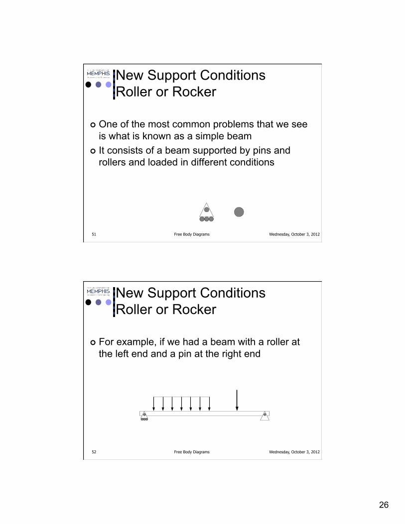
New Support Conditions Roller or Rocker
¢ One of the most common problems that we see is what is known as a simple beam
¢ It consists of a beam supported by pins and rollers and loaded in different conditions
Wednesday, October 3, 2012 Free Body Diagrams 52
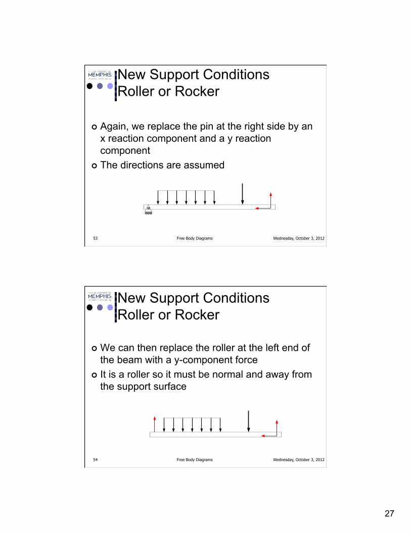
New Support Conditions Roller or Rocker
¢ For example, if we had a beam with a roller at the left end and a pin at the right end
27
Wednesday, October 3, 2012 Free Body Diagrams 53
New Support Conditions Roller or Rocker
¢ Again, we replace the pin at the right side by an x reaction component and a y reaction component
¢ The directions are assumed
Wednesday, October 3, 2012 Free Body Diagrams 54
New Support Conditions Roller or Rocker
¢ We can then replace the roller at the left end of the beam with a y-component force
¢ It is a roller so it must be normal and away from the support surface

28
Wednesday, October 3, 2012 Free Body Diagrams 55
New Support Conditions Roller or Rocker
¢ This is the FBD of the beam ¢ To do the analysis, we could next convert the
distributed load into a point load
Wednesday, October 3, 2012 Free Body Diagrams 56
New Support Conditions Weightless Link
¢ Now that you see the pattern to how we are developing the reactions you may want to see if you can see what this reaction would be
A
B C

29
Wednesday, October 3, 2012 Free Body Diagrams 57
New Support Conditions Weightless Link
¢ Our system is AB ¢ At each end of AB we have a pin connection and
we have no other forces acting on AB.
A
B C
Wednesday, October 3, 2012 Free Body Diagrams 58
New Support Conditions Weightless Link
¢ look at a FBD of the link (AB) ¢ Since we have a pin at each end we can draw an
x and a y reaction at each end
A
B

30
Wednesday, October 3, 2012 Free Body Diagrams 59
New Support Conditions Weightless Link
¢ For ease of explanation, we can label each of the components of the reactions
Ax
Bx
ByAy
Wednesday, October 3, 2012 Free Body Diagrams 60
New Support Conditions Weightless Link
¢ Since we are in Statics, we know that everything must be in equilibrium, so
Ax
Bx
ByAy
0
0x x x
y y y
F A B
F A B
= = −
= = −∑∑

31
Wednesday, October 3, 2012 Free Body Diagrams 61
New Support Conditions Weightless Link
¢ Now we can create a resultant at each end from the components
¢ And since Ax = Bx and Ay = By then A = B
A
B x x
y y
A BA B
==
Wednesday, October 3, 2012 Free Body Diagrams 62
New Support Conditions Weightless Link
¢ We have two forces equal in magnitude but exactly opposite in direction
¢ Sounds a lot like a couple to me
A
B x x
y y
A BA B
==

32
Wednesday, October 3, 2012 Free Body Diagrams 63
New Support Conditions Weightless Link
¢ But we are in equilibrium so the moment on the link must be equal to 0 also
¢ The only way this can be so if for the perpendicular distance between the forces to be equal to 0
A
B x x
y y
A BA B
==
Wednesday, October 3, 2012 Free Body Diagrams 64
New Support Conditions Weightless Link
¢ If the perpendicular distance between the forces is equal to 0 then they have the same line of action
A
B x x
y y
A BA B
==
33
Wednesday, October 3, 2012 Free Body Diagrams 65
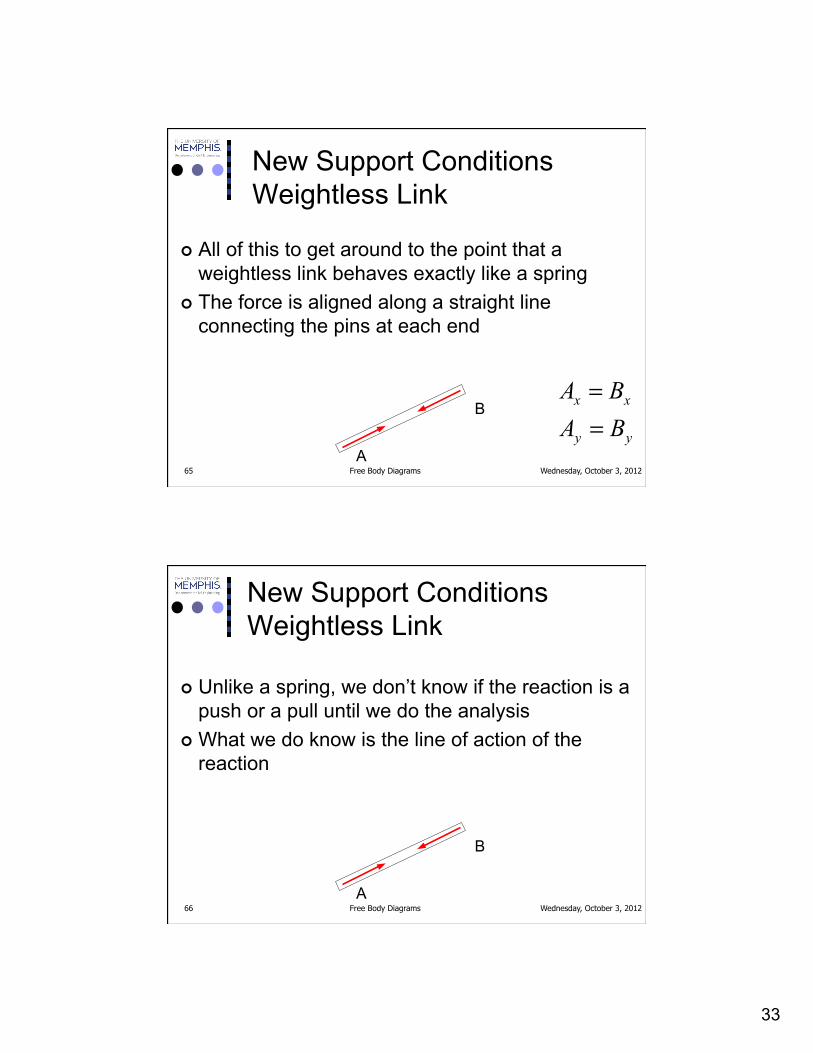
New Support Conditions Weightless Link
¢ All of this to get around to the point that a weightless link behaves exactly like a spring
¢ The force is aligned along a straight line connecting the pins at each end
A
B x x
y y
A BA B
==
Wednesday, October 3, 2012 Free Body Diagrams 66
New Support Conditions Weightless Link
¢ Unlike a spring, we don’t know if the reaction is a push or a pull until we do the analysis
¢ What we do know is the line of action of the reaction
A
B

34
Wednesday, October 3, 2012 Free Body Diagrams 67
New Support Conditions Weightless Link
¢ You will also see this described as a two-force member
A
B
Homework
¢ Problem 5-3 ¢ Problem 5-6 ¢ Problem 5-7 ¢ Problem 5-8
Wednesday, October 3, 2012 Free Body Diagrams 68