Rigging and Assembly Instructions - Clark Johnson Co and Assembly Instructions CONTAINERIZED ......
16
Rigging and Assembly Instructions CONTAINERIZED COOLING TOWERS (C-AT) Bulletin 177A Visit EVAPCO’s Website at: http://www.evapco.com EVAPCO... SPECIALISTS IN HEAT TRANSFER PRODUCTS AND SERVICES. EVAPCO, Inc. — World Headquarters & Research/Development Center EVAPCO, Inc. • P.O. Box 1300 • Westminster, MD 21158 USA PHONE: 410-756-2600 • FAX: 410-756-6450 • E-MAIL: [email protected] EVAPCO, Inc. World Headquarters P.O. Box 1300 Westminster, MD 21158 USA Phone: 410-756-2600 Fax: 410-756-6450 E-mail: [email protected] EVAPCO Asia/Pacific EVAPCO Asia/Pacific Headquarters 1159 Luoning Rd. Baoshan Industrial Zone Shanghai, P. R. China, Postal Code: 200949 Phone: (86) 21-6687-7786 Fax: (86) 21-6687-7008 E-mail: [email protected] EVAPCO Europe EVAPCO Europe BVBA European Headquarters Industrieterrein Oost 4010 3700 Tongeren, Belgium Phone: (32) 12-395029 Fax: (32) 12-238527 E-mail: [email protected] EVAPCO East 5151 Allendale Lane Taneytown, MD 21787 USA Phone: 410-756-2600 Fax: 410-756-6450 E-mail: [email protected] EVAPCO Midwest 1723 York Road Greenup, IL 62428 USA Phone: 217-923-3431 Fax: 217-923-3300 E-mail: [email protected] EVAPCO West 1900 West Almond Avenue Madera, CA 93637 USA Phone: 559-673-2207 Fax: 559-673-2378 E-mail: [email protected] EVAPCO Iowa 925 Quality Drive Lake View, IA 51450 USA Phone: 712-657-3223 Fax: 712-657-3226 EVAPCO Iowa Sales & Engineering 215 1st Street, NE P.O. Box 88 Medford, MN 55049 USA Phone: 507-446-8005 Fax: 507-446-8239 E-mail: [email protected] EVAPCO Northwest 5775 S.W. Jean Road, Suite 104 Lake Oswego, Oregon 97035 USA Phone: 503-639-2137 Fax: 503-639-1800 EVAPCO Newton 701 East Jourdan Street Newton, IL 62448 USA Phone: 618-783-3433 Fax: 618-783-3499 E-mail: [email protected] EVAPCO-BLCT Dry Cooling, Inc. 981 US Highway 22 West Bridgewater, New Jersey 08807 USA Phone: 1-908-379-2665 E-mail: [email protected] Refrigeration Valves & Systems Corporation A wholly owned subsidiary of EVAPCO, Inc. 1520 Crosswind Dr. Bryan, TX 77808 USA Phone: 979-778-0095 Fax: 979-778-0030 E-mail: [email protected] EvapTech, Inc. A wholly owned subsidiary of EVAPCO, Inc. 8331 Nieman Road Lenexa, KS 66214 USA Phone: 913-322-5165 Fax: 913-322-5166 E-mail: [email protected] Tower Components, Inc. A wholly owned subsidiary of EVAPCO, Inc. 5960 US HWY 64E Ramseur, NC 27316 Phone: 336-824-2102 Fax: 336-824-2190 E-mail: [email protected] EVAPCO Europe, S.r.l. Via Ciro Menotti 10 I-20017 Passirana di Rho Milan, Italy Phone: (39) 02-939-9041 Fax: (39) 02-935-00840 E-mail: [email protected] EVAPCO Europe, S.r.l. Via Dosso 2 23020 Piateda Sondrio, Italy EVAPCO Europe GmbH Insterburger Straße 18 40670 Meerbusch, Germany Phone: (49) 2159-69560 Fax: (49) 2159-695611 E-mail: [email protected] Flex coil a/s A wholly owned subsidiary of EVAPCO, Inc. Knøsgårdvej 115 DK-9440 Aabybro Denmark Phone: (45) 9824 4999 Fax: (45) 9824 4990 E-mail: [email protected] EVAPCO S.A. (Pty.) Ltd. A licensed manufacturer of EVAPCO, Inc. 18 Quality Road Isando 1600 Republic of South Africa Phone: (27) 11-392-6630 Fax: (27) 11-392-6615 E-mail: [email protected] Evap Egypt Engineering Industries Co. A licensed manufacturer of EVAPCO, Inc. 5 El Nasr Road Nasr City, Cairo, Egypt Phone: 2 02 24022866 /2 02 24044997 Fax: 2 02 24044667 / 2 02 24044668 E-mail: [email protected] / [email protected] EVAPCO (Shanghai) Refrigeration Equipment Co., Ltd. 1159 Luoning Rd., Baoshan Industrial Zone Shanghai, P.R. China, Postal Code: 200949 Phone: (86) 21-6687-7786 Fax: (86) 21-6687-7008 E-mail: marketing@evapcochina.com Beijing EVAPCO Refrigeration Equipment Co., Ltd. No. 13 Yanxi Avenue, Yanqi Development Zone Huai Rou County Beijing, P.R. China Postal code 101407 Phone: (86) 10 6166-7238 Fax: (86) 10 6166-7395 E-mail: [email protected] EVAPCO Australia (Pty.) Ltd. 34-42 Melbourne Road P.O. Box 436 Riverstone, N.S.W. Australia 2765 Phone: (61) 2 9627-3322 Fax: (61) 2 9627-1715 E-mail: [email protected] EVAPCO Composites Sdn. Bhd No. 70 (Lot 1289) Jalan Industri 2/3 Rawang Integrated Industrial Park Rawang, Selangor, 48000 Malaysia Phone: 60 3 6092-2209 Fax: 60 3 6092-2210 EvapTech Asia Pacific Sdn. Bhd A wholly owned subsidiary of EvapTech, Inc. B-6-1, IOI Boulevard Jalan Kenari 5, Bandar Puchong Jaya 47170 Puchong, Selangor Darul Ehsan Malaysia Phone: (60-3) 8070-7255 Fax: (60-3) 8070-5731 E-mail: [email protected] EVAPCO North America EVAPCO Products are Manufactured Wordwide
Transcript of Rigging and Assembly Instructions - Clark Johnson Co and Assembly Instructions CONTAINERIZED ......

Rigging andAssembly Instructions
CONTAINERIZED COOLING TOWERS (C-AT)
Bulletin 177A
Visit EVAPCO’s Website at: http://www.evapco.com
EVAPCO...SPECIALISTS IN HEAT TRANSFER PRODUCTS AND SERVICES.
EVAPCO, Inc. — World Headquarters & Research/Development Center
EVAPCO, Inc. • P.O. Box 1300 • Westminster, MD 21158 USAPHONE: 410-756-2600 • FAX: 410-756-6450 • E-MAIL: [email protected]
EVAPCO, Inc. World HeadquartersP.O. Box 1300Westminster, MD 21158 USAPhone: 410-756-2600 Fax: 410-756-6450E-mail: [email protected]
EVAPCO Asia/Pacific
EVAPCO Asia/Pacific Headquarters1159 Luoning Rd. Baoshan Industrial ZoneShanghai, P. R. China, Postal Code: 200949Phone: (86) 21-6687-7786Fax: (86) 21-6687-7008E-mail: [email protected]
EVAPCO Europe
EVAPCO Europe BVBAEuropean HeadquartersIndustrieterrein Oost 40103700 Tongeren, BelgiumPhone: (32) 12-395029Fax: (32) 12-238527E-mail: [email protected]
EVAPCO East5151 Allendale LaneTaneytown, MD 21787 USAPhone: 410-756-2600Fax: 410-756-6450E-mail: [email protected]
EVAPCO Midwest1723 York RoadGreenup, IL 62428 USAPhone: 217-923-3431Fax: 217-923-3300E-mail: [email protected]
EVAPCO West1900 West Almond AvenueMadera, CA 93637 USAPhone: 559-673-2207Fax: 559-673-2378E-mail: [email protected]
EVAPCO Iowa925 Quality DriveLake View, IA 51450 USAPhone: 712-657-3223Fax: 712-657-3226
EVAPCO IowaSales & Engineering215 1st Street, NEP.O. Box 88Medford, MN 55049 USAPhone: 507-446-8005Fax: 507-446-8239E-mail: [email protected]
EVAPCO Northwest5775 S.W. Jean Road, Suite 104Lake Oswego, Oregon 97035 USAPhone: 503-639-2137Fax: 503-639-1800
EVAPCO Newton701 East Jourdan StreetNewton, IL 62448 USAPhone: 618-783-3433Fax: 618-783-3499E-mail: [email protected]
EVAPCO-BLCT Dry Cooling, Inc.981 US Highway 22 WestBridgewater, New Jersey 08807 USA Phone: 1-908-379-2665E-mail: [email protected]
Refrigeration Valves & Systems CorporationA wholly owned subsidiary of EVAPCO, Inc.1520 Crosswind Dr.Bryan, TX 77808 USAPhone: 979-778-0095Fax: 979-778-0030E-mail: [email protected]
EvapTech, Inc.A wholly owned subsidiary of EVAPCO, Inc.8331 Nieman RoadLenexa, KS 66214 USAPhone: 913-322-5165Fax: 913-322-5166E-mail: [email protected]
Tower Components, Inc.A wholly owned subsidiary of EVAPCO, Inc.5960 US HWY 64ERamseur, NC 27316Phone: 336-824-2102Fax: 336-824-2190E-mail: [email protected]
EVAPCO Europe, S.r.l.Via Ciro Menotti 10I-20017 Passirana di RhoMilan, ItalyPhone: (39) 02-939-9041Fax: (39) 02-935-00840E-mail: [email protected]
EVAPCO Europe, S.r.l.Via Dosso 223020 Piateda Sondrio, Italy
EVAPCO Europe GmbHInsterburger Straße 1840670 Meerbusch, GermanyPhone: (49) 2159-69560Fax: (49) 2159-695611E-mail: [email protected]
Flex coil a/sA wholly owned subsidiary of EVAPCO, Inc.Knøsgårdvej 115DK-9440 Aabybro DenmarkPhone: (45) 9824 4999Fax: (45) 9824 4990E-mail: [email protected]
EVAPCO S.A. (Pty.) Ltd.A licensed manufacturer of EVAPCO, Inc.18 Quality RoadIsando 1600Republic of South AfricaPhone: (27) 11-392-6630Fax: (27) 11-392-6615E-mail: [email protected]
Evap Egypt Engineering Industries Co.A licensed manufacturer of EVAPCO, Inc.5 El Nasr RoadNasr City, Cairo, EgyptPhone: 2 02 24022866 /2 02 24044997Fax: 2 02 24044667/2 02 24044668E-mail: [email protected] / [email protected]
EVAPCO (Shanghai) Refrigeration Equipment Co., Ltd.1159 Luoning Rd., Baoshan Industrial ZoneShanghai, P.R. China, Postal Code: 200949Phone: (86) 21-6687-7786Fax: (86) 21-6687-7008E-mail: [email protected]
Beijing EVAPCO Refrigeration Equipment Co., Ltd.No. 13 Yanxi Avenue, Yanqi DevelopmentZoneHuai Rou CountyBeijing, P.R. ChinaPostal code 101407Phone: (86) 10 6166-7238Fax: (86) 10 6166-7395E-mail: [email protected]
EVAPCO Australia (Pty.) Ltd.34-42 Melbourne RoadP.O. Box 436Riverstone, N.S.W. Australia 2765Phone: (61) 2 9627-3322Fax: (61) 2 9627-1715E-mail: [email protected]
EVAPCO Composites Sdn. BhdNo. 70 (Lot 1289) Jalan Industri 2/3Rawang Integrated Industrial ParkRawang, Selangor, 48000 MalaysiaPhone: 60 3 6092-2209Fax: 60 3 6092-2210
EvapTech Asia Pacific Sdn. BhdA wholly owned subsidiary of EvapTech, Inc.B-6-1, IOI BoulevardJalan Kenari 5, Bandar Puchong Jaya47170 Puchong, Selangor Darul EhsanMalaysiaPhone: (60-3) 8070-7255Fax: (60-3) 8070-5731E-mail: [email protected]
EVAPCO North America
EVAPCO Products are Manufactured Wordwide

2
C-AT Containerized Products
Method of Shipment
The C-AT product line has been designed to fit in a standardshipping container. C-AT towers are shipped with the top (fan)and bottom (basin) sections (less vertical supports) mountedtogether for shipment, as shown in Figure 1. The middle (fill)section is shipped separately, as shown in Figure 2. Thesesections have mating flanges and will join together in awaterproof joint when sealed and bolted together as described
in the following instructions. The vertical supports, all ancillaryequipment, and parts ship disassembled and packaged in thebasin section. Miscellaneous items, such as sealer tape, self-tapping screws and any other required materials, are packagedand placed inside the rigging box and shipped in the basinsection as well, as shown in Figure 3.
Figure 1 – Skidded fan and basin sections
Figure 2 – Skidded fill section
Basin
Fan Section
Figure 3 – Basin shipping arrangement
Rigging Box
Louvers
Fan MotorCovers
VerticalSupports
Fan Motors

3
C-AT Containerized Products
Storage & Excessive Heat Precautions
The temperature inside shipping containers can be significantlyhigher than ambient outdoor temperatures. Since excessiveheat build-up can cause damage to the PVC components suchas drift eliminators or air inlet louvers. Units shipped to orthrough particularly hot climates should utilize ʻopen topʼ
shipping containers or otherwise make arrangements to havethe PVC components shipped separately. Do not place tarpsor other coverings over the top of the units. Tarps could have asimilar heat trapping effect resulting in damage to PVCcomponents. For extended storage beyond six months, rotatethe fan and fan motor shaft(s) monthly. The fan shaft bearingsshould be purged and re-greased prior to start-up.
Unloading
C-AT towers are loaded into shipping containers with the fillsection closest to the door. This minimizes the handling of this(heaviest) section and facilitates unloading of all components.Evapco recommends that C-ATs be unloaded from their
shipping containers at the receiving port and transported to thefinal destination using a flatbed truck. Unloading of bothsections can be achieved by the use of straps or chains loopedthrough the skid of each section and connected to a forklift.
If a loading dock is available at the jobsite, the container maybe transported to its final destination and similarly unloaded.However, if a loading dock is not available the container can beoff-loaded to ground level and unloaded using a small ramp toadjust for the height difference between the ground and theinside of the container.
WARNING! Caution must be exercised when handlingthe loaded shipping container. The C-AT sections are ofunequal weight and may cause excessive shifting ortilting of the container during handling.
Structural Steel Support
Two structural “I” beams running the length of the unit arerequired for supporting the unit. These beams should belocated underneath the outer flanges of the unit as shown inFigure 4.
Mounting holes, 3/4” (19mm) in diameter, are located in thebottom flange for bolting to the structural steel (see certifiedprint for exact bolt hole location). Bolt the bottom section to thesteel support before rigging the top section. Follow the rigginginstructions to ensure proper sequence of section installation.
Beams should be sized in accordance with accepted structuralpractices. Maximum deflection of the beam under the unit isrecommended to be 1/360 of the unit length, not to exceed 1/2”(13mm). Deflection may be calculated by using 55% of theoperating weight as a uniform load on each beam (see certifiedprint for operating weight).
The supporting “I” beams should be level before setting theunit. Do not level the unit by shimming between the bottomflange and the beams as this will not provide properlongitudinal support.
Figure 4 – Steel Support

4
C-AT Containerized Products
C-AT RIGGING AND ASSEMBLY
There are (8) basic steps required to assemble a C-AT:
Step #1: Remove Fan Section from Basin Section
Step #2: Rig Fan Section onto Fill Section
Step #3: Rig Basin Section
Step #4: Install Vertical Supports in Basin Section
Step #5: Rig Fan/Fill Section onto Basin section
Step #6: Install WST Air Inlet Louvers
Step #7: Install Motors and Covers
Step #1Remove Fan Section from Basin Section
Remove all shipping channels holding basin and fan togetherby removing the hardware securing the shipping channels tothe wood beams and chocks as shown in Figure 5.
Prior to rigging the fan section onto the fill section, sealer tapemust be applied to the top of the fill section. The top flanges onthe fill section and bottom flanges on the fan section should bewiped down to remove any dirt or moisture. One layer of sealertape should be placed over the mounting hole centerline on theside flanges. Apply two strips of sealer tape, one partiallyoverlapping the other, on the end flanges. The sealer tapeshould overlap on the corners as shown in Figure 6. Do notsplice the sealer tape along the end flanges and preferably noton the side flanges if it can be avoided. Always remove thepaper backing from the sealer tape.
2 OVERLAPPINGLAYERS OF SEALER
ON THE ENDS
1 LAYER OF SEALER CENTEREDOVER THE MOUNTING HOLES
ENDSIDE
Figure 6 - Proper Sealer Tape Application
Figure 5 – Removal of shipping channels

5
C-AT Containerized Products
H
"U" BOLTS
Figure 8b – Lifting of fan section, two-fan units–“H” Dimension
H
SPREADERBARS
"U" BOLTS
Figure 9 – Extended Lifting of fan section – “H” Dimension
Once the shipping channels have been removed from betweenthe basin and fan section and sealer tape has been applied tothe top of the fill section, the fan section should be lifted usingthe U- bolts located at the top corners of the fan section asshown in Figures 7 and 8a and 8b.
The hook of the crane must be a minimum dimension of “H”above the top of the section being lifted to prevent unduestrain on the lifting devices. See Table 1 for the minimum “H”dimension. If the “H” dimension cannot be met with a hook, aspreader bar should be used as shown in Figure 7. Thespreader bar should be approximately the same length as the unit.
Figure 7 – Lifting of fan section
H
"U" BOLTS
Figure 8a – Lifting of fan section, single-fan units–“H” Dimension
EXTENDED LIFTSThe preferred method for extended lifts is to use slingsunder the unit (See Figure 9). Spreader bars must alwaysbe used between the cables at the top of the section toprevent damage to the upper flanges or fan cylinders.
6
C-AT Containerized Products
Tower Length Min. ‘H’ Dimension
9 Feet (2.7 meters) 9 Feet (2.7 meters)12 Feet (3.6 meters) 12 Feet (3.6 meters)14 Feet (4.3 meters) 14 Feet (4.3 meters)18 Feet (5.5 meters) 17 Feet (5.2 meters)
Table 1 – Minimum ʻHʼ Dimension for Fan Sections
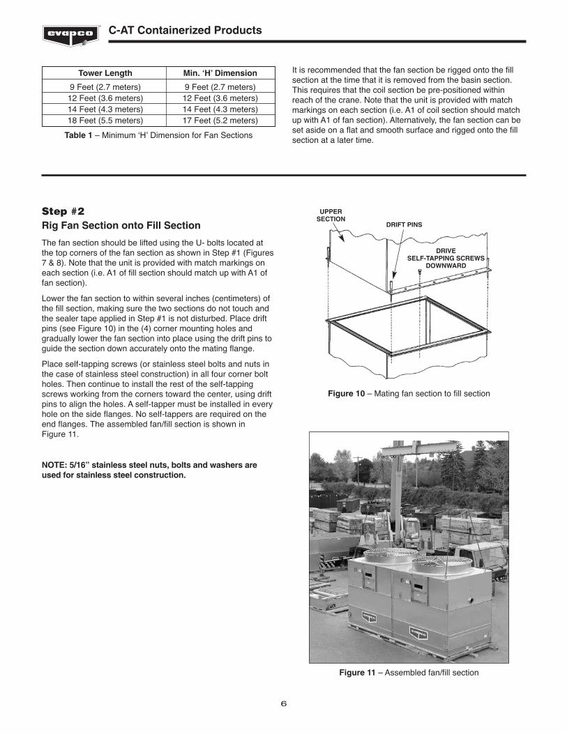
It is recommended that the fan section be rigged onto the fillsection at the time that it is removed from the basin section.This requires that the coil section be pre-positioned withinreach of the crane. Note that the unit is provided with matchmarkings on each section (i.e. A1 of coil section should matchup with A1 of fan section). Alternatively, the fan section can beset aside on a flat and smooth surface and rigged onto the fillsection at a later time.
Step #2Rig Fan Section onto Fill Section
The fan section should be lifted using the U- bolts located atthe top corners of the fan section as shown in Step #1 (Figures7 & 8). Note that the unit is provided with match markings oneach section (i.e. A1 of fill section should match up with A1 offan section).
Lower the fan section to within several inches (centimeters) ofthe fill section, making sure the two sections do not touch andthe sealer tape applied in Step #1 is not disturbed. Place driftpins (see Figure 10) in the (4) corner mounting holes andgradually lower the fan section into place using the drift pins toguide the section down accurately onto the mating flange.
Place self-tapping screws (or stainless steel bolts and nuts inthe case of stainless steel construction) in all four corner boltholes. Then continue to install the rest of the self-tappingscrews working from the corners toward the center, using driftpins to align the holes. A self-tapper must be installed in everyhole on the side flanges. No self-tappers are required on theend flanges. The assembled fan/fill section is shown in Figure 11.
NOTE: 5/16” stainless steel nuts, bolts and washers areused for stainless steel construction.
Figure 10 – Mating fan section to fill section
UPPERSECTION
DRIFT PINS
DRIVE SELF-TAPPING SCREWS
DOWNWARD
Figure 11 – Assembled fan/fill section

Step #3Rig Basin Section
Remove the fan section from the basin section as discussed inStep #1.
The basin section can then be lifted using the lifting bracketslocated in the inside corners of the basin section as shown inFigures 12a and b. The hook of the crane must be a minimumdimension of “H” above the top of the section being lifted toprevent undue strain on the lifting devices. See Table 2 for theminimum “H” dimension. If the “H” dimension cannot be metwith a hook, a spreader bar should be used. The spreaderbar should be approximately the same length as the unit.
Position the basin section on the unit steel supports and boltinto place per Figure 4. Bolt the basin section to the steelsupport before rigging the fill section.
The lifting devices alone should NOT be used for extended liftsor where any hazard exists. For extended lifts, safety slingsmust be provided under the sections in combination with thelifting devices on the unit as described below.
7
C-AT Containerized Products
Figure 12b – Lifting of basin section, two-fan units–“H” Dimension
Tower Length Min. ‘H’ Dimension
9 Feet (2.7 meters) 9 Feet (2.7 meters)12 Feet (3.6 meters) 12 Feet (3.6 meters)14 Feet (4.3 meters) 14 Feet (4.3 meters)18 Feet (5.5 meters) 17 Feet (5.2 meters)
Table 2 – Minimum ʻHʼ Dimension for Fan Sections
EXTENDED LIFTSThe preferred method for extended lifts is to useslings under the unit (See Figure 13). Spreader barsmust always be used between the cables at the top ofthe section to prevent damage to the upper flanges orfan cylinders. H
SPREADERBARS
LIFTINGDEVICES
Figure 13 – Extended Lifting of fan section–“H” Dimension
Figure 12a – Lifting of basin section, single-fan units–“H” Dimension

8
C-AT Containerized Products
Step #4Install Vertical Supports in Basin Section
Once the basin has been set into its final position and boltedto the steel, the lifting brackets should be removed from themounting angles for the pan vertical supports as shown inFigure 14.
Unpack the components shipped in the basin and set them
aside near the unit. Prepare the basin section for assembly bymatching the marks on the vertical posts with those on thebasin brackets and laying out the vertical posts in their properlocation, as shown in Figure 15.
Figure 14 – Lifting Bracket Removed From Mounting Angles
Figure 15 – Vertical posts layout
9
C-AT Containerized Products
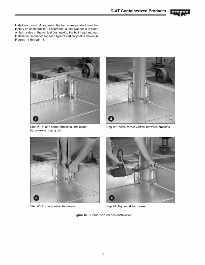
Install each vertical post using the hardware installed from thefactory on each bracket. Ensure that a lock-washer is in placeon both sides of the vertical post next to the bolt head and nut.Installation sequence for each type of vertical post is shown inFigures 16 through 18.
Figure 16 – Corner vertical post installation
Step #1: Clean corner brackets and locatehardware in rigging box
Step #2: Install corner vertical between brackets
Step #3: Loosely install hardware Step #4: Tighten all hardware
1 2
3 4
10
C-AT Containerized Products
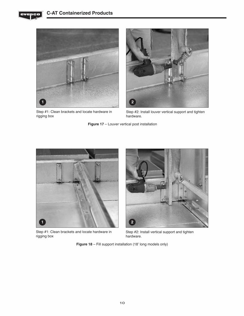
Step #1: Clean brackets and locate hardware inrigging box
Step #2: Install louver vertical support and tightenhardware.
1 2
Figure 17 – Louver vertical post installation
Step #1: Clean brackets and locate hardware inrigging box
Step #2: Install vertical support and tightenhardware.
1 2
Figure 18 – Fill support installation (18ʼ long models only)

11
C-AT Containerized Products
Figure 19 – Assembled basin section
The final step in assembling the basin is installing the cross-braces as shown in Figure 19 (use ½” x 1-¼” bolts and ½”lock-washer and nut).
Some drilling (9/16 Ø) on vertical support tabs is required.
Applying Sealer Tape
Prior to rigging the fan/fill sections onto the basin section, sealertape must be applied. The top surfaces of the basin verticalposts and bottom flanges on the fill section should be wipeddown to remove any dirt or moisture. Sealer tape should beplaced over the mounting hole centerline on the vertical posts.Apply two strips of sealer tape, one partially overlapping theother. The sealer tape should overlap on the corners as shown inFigure 20. Do not splice the sealer tape along the end flangesand preferably not on the side flanges if it can be avoided.Always remove the paper backing from the sealer tape.
1 LAYER OF SEALERCENTERED OVER THE
MOUNTING HOLES
2 OVERLAPPING LAYERSOF SEALER ON THE ENDS
Figure 20 – Proper sealer tape application

12
C-AT Containerized Products
Step #5Rig Fan/Fill Section onto Basin section
All “U” bolts on the top section are to be used for lifting andfinal positioning of the unit as shown in Figure 21. The hook ofthe crane must be a minimum dimension of “H” above the topof the unit being lifted to prevent undue strain on the “U” bolts.See Table 3 for minimum “H” dimension.
The “U” bolts should not be used for extended lifts or whereany hazard exists unless safety slings are employed under thesection. (See “Extended Lifts” on page 13 for properarrangement.)
The spreader beam must be a minimum dimension “H” abovethe top section being lifted to prevent undue strain on the liftingears. See Table 3 for the minimum “H” dimension. These liftingdevices should not be used for extended lifts or where anyhazard exists unless safety slings are employed under thesection. (See “Extended Lifts” in Step #1 for proper arrangementusing the lifting ears instead of the fan section U-Bolts.)
Important: The lifting devices and “U” bolts should beused for final positioning only and for lifting where nodanger exists. If they are used for extended lifts, safetyslings should be provided under the sections.
Safety slings and skids should be removed before finalpositioning of the unit.
Figure 21 – Four point lift
Tower Length Min. ‘H’ Dimension
9 Feet (2.7 meters) 9 Feet (2.7 meters)
12 Feet (3.6 meters) 12 Feet (3.6 meters)
14 Feet (4.3 meters) 14 Feet (4.3 meters)
18 Feet (5.5 meters) 17 Feet (5.2 meters)
Table 3 – Minimum ʻHʼ Dimension for Fan/Fill Sections
“U” BOLTS
The preferred method for extended lifts is to use slingsunder the unit (see Figure 22). Spreader bars should alwaysbe used between the cables at the top of the section toprevent damage to the upper flanges or fan cylinders.

13
C-AT Containerized Products
Lower the fan/fill section to within several inches (centimeters)of the basin vertical posts, making sure the two sections do nottouch and the sealer is not disturbed. Place drift pins (seeFigure 22) in at least (3) of the corner mounting holes andgradually lower the fan/coil section into place using the driftpins to guide the section down accurately onto the matingvertical posts. Place washers, nuts and bolts in all four cornerbolt holes. Then continue to install the rest of the washers, nutsand bolts on the remaining vertical posts.
NOTE: 5/16” stainless steel nuts, bolts and washers areused for stainless steel construction.
SPREADERBARS
“U” BOLTS
H
Figure 22 – Top Sections, Models 27-518-27-918
Step #6Install WST Air Inlet Louvers
Air inlet louvers are shipped with an integral metal frame forease of handling and maintenance. Install all louvers intoplace, ensuring that the drain holes are located on the lowerframe, facing the interior of the basin. The louver retainingangles should then be installed and secured with plastic quick-release knobs. Finally, install plastic cap on wing-nut bolts, asshown in Figure 26, to prevent loss of the wing-nuts duringmaintenance.
Figure 23 – Installed WST louver
EXTENDED LIFTSThe preferred method for extended lifts is to useslings under the unit (See Figure 13). Spreader barsmust always be used between the cables at the top ofthe section to prevent damage to the upper flanges orfan cylinders.
14
C-AT Containerized Products
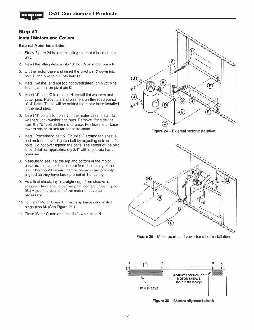
Step #7Install Motors and Covers
External Motor Installation
1. Study Figure 24 before installing the motor base on theunit.
2. Insert the lifting device into “U” bolt A on motor base B.
3. Lift the motor base and insert the pivot pin C down intohole E and pivot pin F into hole D.
4. Install washer and nut (do not overtighten) on pivot pins.Install jam nut on pivot pin C.
5. Insert “J” bolts G into holes H. Install flat washers andcotter pins. Place nuts and washers on threaded portionof “J” bolts. These will be behind the motor base installedin the next step.
6. Insert “J” bolts into holes J in the motor base. Install flatwashers, lock washer and nuts. Remove lifting devicefrom the “U” bolt on the motor base. Position motor basetoward casing of unit for belt installation.
7. Install Powerband belt K (Figure 25) around fan sheaveand motor sheave. Tighten belt by adjusting nuts on “J”bolts. Do not over tighten the belts. The center of the beltshould deflect approximately 3/4” with moderate handpressure.
8. Measure to see that the top and bottom of the motorbase are the same distance out from the casing of theunit. This should ensure that the sheaves are properlyaligned as they have been pre-set at the factory.
9. As a final check, lay a straight edge from sheave tosheave. There should be four point contact. (See Figure26.) Adjust the position of the motor sheave asnecessary.
10. To install Motor Guard L, match up hinges and installhinge pins M. (See Figure 25.)
11. Close Motor Guard and install (2) wing bolts N.
FAN SHEAVE
ADJUST POSITION OFMOTOR SHEAVE
(only if necessary)
1 2 3 4
Figure 24 – External motor installation
Figure 25 – Motor guard and powerband belt installation
Figure 26 – Sheave alignment check

15
General Information - Start-up & Maintenance
General Information - Start-up & Maintenance
Start-up Details
Shipping Chocks and Debris
Remove any chocks that have been placed inside the unit forshipping purposes. Be sure to remove the chocks from betweenthe fan and fan guard if applicable. Clean all debris from thebasin prior to start-up. Close and secure all access doors.
StrainerCheck the strainers, ifapplicable, in thebasin section to makecertain they are in theproper location, alongside of the anti-vortexhood (See Figure27).
Screens
Protective fan screens are provided across the top of the fancylinders of all models. Check and tighten all bolts.
Float Valve Adjustment
The float valve is pre-set at the factory; however, adjustmentshould be checked after rigging. The float valve should beadjusted so that the centerline of the float is 11 inches (28 cm)from the basin bottom. Raise or lower the float by using thewing nuts on the vertical threaded rod only. Do not adjust thehorizontal rod.
Starting Sequence
Before starting the unit, check that all access openings, safetyscreens and covers are in place. Start the unit as outlinedbelow:
1. Fill the pan to the overflow level.2. Bump start and check the fan(s) for proper rotation.
Directional arrows are placed on the side of the fancylinder.
Maintenance
Once the installation is complete and the unit is turned on, it isimportant that it be properly maintained. Maintenance is notdifficult or time-consuming but must be done regularly toassure full performance of the unit. Refer to the maintenanceinstructions enclosed with the unit for proper maintenanceprocedures.
Freeze Protection
Proper freeze protection must be provided if the unit is locatedin a cold climate. Refer to maintenance instructions as well asproduct bulletins for further information.
Figure 27 – Strainer Location
WARNING!DO NOT WALK ON THE FAN SCREENS AT ANY TIME!

EVAPCO, Inc. • P.O. Box 1300 • Westminster, MD 21158 USAPHONE: 410-756-2600 • FAX: 410-756-6450 • E-MAIL: [email protected]
©2014 EVAPCO, Inc.
50 Hz MOTORS 60 Hz MOTORS
Unit Length Unit Length
9' 12' 14' 18' 9' 12' 14' 18'
Sump Box Mounting Hardware
3/8" x 1" Bolt, Lock Washer, Nut 12 12 12 12
Sealer Tape 1 1 1 1
Field Joint
1/2" x 1-1/4" Bolt, (2) Washer, Lock Washer, Nut 20 20 20 32 20 20 20 32
Sealer Tape 2 2 2 2 2 2 2 2
Pan - Pipe Braces
1/2" x 1-1/4" Bolt, Lock Washer, Nut 4 4 8 4 4 8
Float Rod Assembly
Assembly 1 1 1 1 1 1 1 1
Vertical Hardware
1/2" (2) Bolt, Washer, Large Washer, 12 12 12 20 12 12 12 20
(2) Lock Washer, (2) Nut
Louver Handles
3/8" Phenolic handles and End Caps 16 16 16 24 16 16 16 24
Center Support - 18 foot only
5/16" x 1" Bolt, (2) Washer, Lock Washer, Nut 8 8
Fan to Casing Section Joint
5/16" x 1" Tapper 45 60 70 90 45 60 70 90
Sealer Tape 2 2 3 3 2 2 3 3
Table 4 - Rigging Hardware
Rigging Hardware Parts List
The following table lists those parts which are shipped togetherwith the unit(s) for field assembly and/or spare parts.
C-AT RIGGING BOX