RIDGE RACER - XMissionarcarc.xmission.com/PDF_Arcade_Manuals_and_Schematics/Ridge Racer... ·...
24
RIDGE RACER Operators Manual
Transcript of RIDGE RACER - XMissionarcarc.xmission.com/PDF_Arcade_Manuals_and_Schematics/Ridge Racer... ·...

RIDGE RACER
Operators Manual

Page 2
1 9 93 Ltd - all rights reserved
No part of this publication may be reproduced by any mechanical, photographic or electronicprocess, or in the form of phonographic recording, nor may it be stored in a retrieval system,transmitted or otherwise copied for public or private use, without permission from namco Ltd.
Published by:BRENT LEISURE Ltd.Unit 1 Brent Crescent,London. NW10 0QT
Phone:- 081-965-0550Fax:- 081-961-0574

Page 3
Contents1111
1.1.. SPECIFICATION S........................................................................................ 44442. PRECAUTION S ................................................................................................. 5555
2-1 Cautions When Installing. .............................................................................................. 52-2 Caution When Handling. ................................................................................................ 52-3 When Transporting. ........................................................................................................ 5
3. MAJOR COMPONENT S............................................................................. 6666This is already fitted at the factory ............................................................................................ 7
........................................................................................................................................................................................ 77774-1 Connecting the Main Body Assy and the Base Assy ..................................................... 74.2 Adjusting the Level Adjustors ........................................................................................ 74.3 Fixing the Signboard Assy ............................................................................................. 7
5. SIDE PANEL S................................................................................................. 88885-1 Removing the Side Boards (R) and (L) .......................................................................... 85-2 Removing the Dashboard Covers (R) and (L) ................................................................ 8
6. ADJUSTMENT S. . . . . . . . . . . . . . . . . . . . . . . . . . . . . . . . . . . . . . . . . . . . . . . . . . . . . . . . . . . . . . . 99996-1 Turning on the Power ..................................................................................................... 96-2 Switches for Adjustments ............................................................................................... 96-3 Test Mode ..................................................................................................................... 106-3-1 Setting the Game Fee and So On (On the Coin Options Screen) ................................. 116-3-2 Changing the Game Settings (on the Game Options Screen) ...................................... 126-3-3 Switch Test ................................................................................................................... 136-3-4 Sound Test (Adjusting the Sound Volume).................................................................. 146-4 Adjusting the Game After Replacing Parts (Initializing the Game) ............................. 15
7. HOW TTTTO PLAY............................................................................................168-1 Removing the Game Printed Circuit Board (PCB) ...................................................... 178-2 Removing the Shield Case............................................................................................ 188-3 Removing the Power Control Panel ............................................................................. 188-4 Signboard Assy ............................................................................................................. 188-4-1 Replacing the Fluorescent Lamp .................................................................................. 188-6 AB Pedal Assy (Replacing the Control) ....................................................................... 198-7 Clutch Pedal Assy (Replacing the Micro Switch) ........................................................ 208-8 Steering Assy ................................................................................................................ 208-8-1 Replacing the control .................................................................................................... 208-8-2 Replacing The Steering Wheel ..................................................................................... 208-9 Gear Shift Assy (removing) .......................................................................................... 218-10 Replacing the Speaker .................................................................................................. 218-11 Replacing the Monitor .................................................................................................. 22
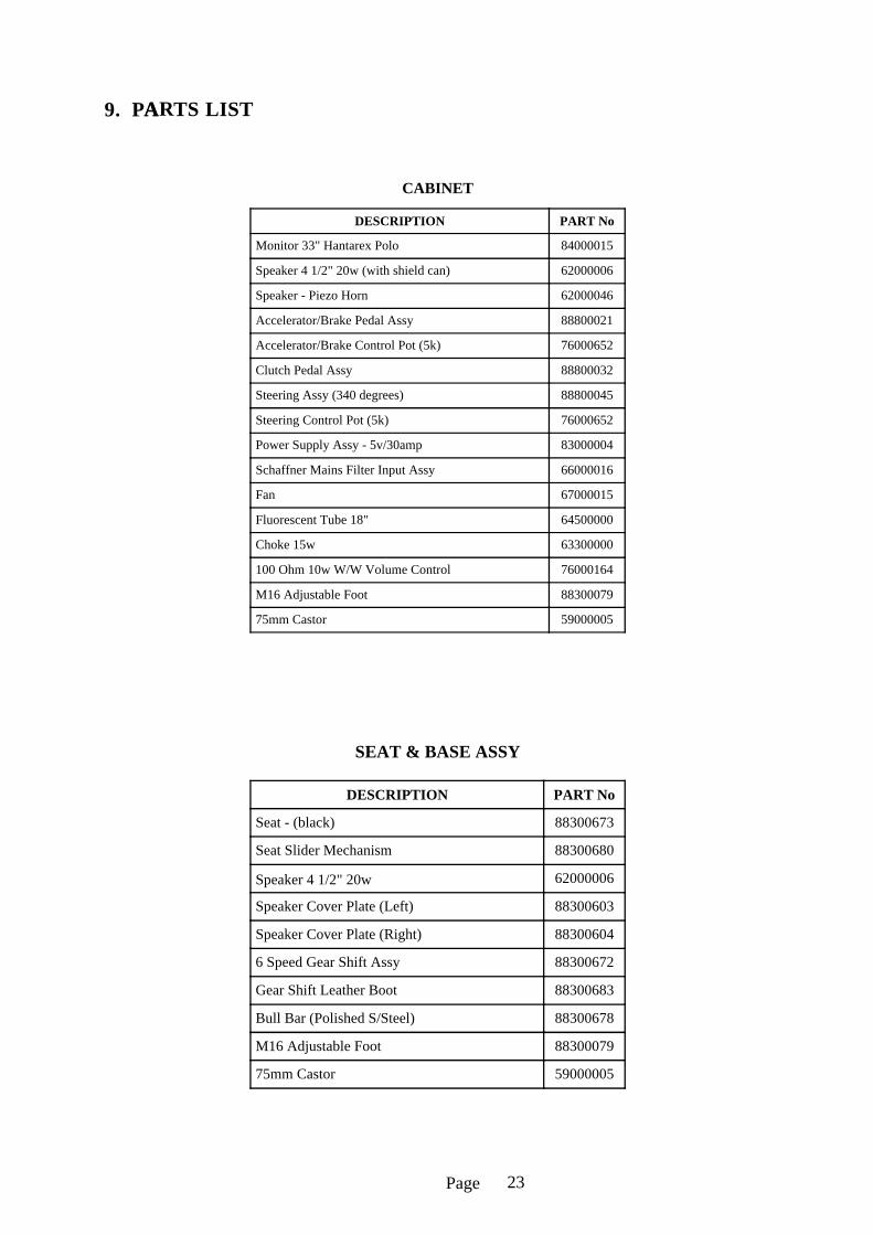
9. PARTS LIST................................................................................................. . 23
4. INSTALLATION.......
Page
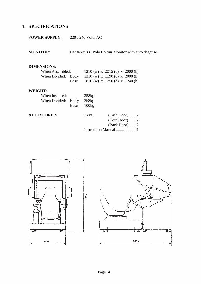
1. SPECIFICATIONS
POWER SUPPLY: 220 / 240 Volts AC
MONITOR: Hantarex 33" Polo Colour Monitor with auto degause
DIMENSIONS:When Assembled: 1210 (w) x 2015 (d) x 2000 (h)When Divided: Body 1210 (w) x 1190 (d) x 2000 (h)
Base 810 (w) x 1250 (d) x 1240 (h)
WEIGHT:When Installed: 358kgWhen Divided: Body 258kg
Base 100kg
ACCESSORIES Keys: (Cash Door) ...... 2(Coin Door) ...... 2(Back Door) ...... 2
Instruction Manual ................... 1
4
Page
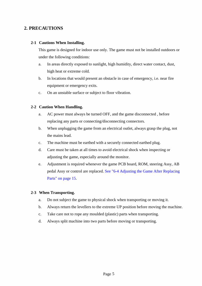
2. PRECAUTIONS
2-1 Cautions When Installing.
This game is designed for indoor use only. The game must not be installed outdoors or
under the following conditions:
a. In areas directly exposed to sunlight, high humidity, direct water contact, dust,
high heat or extreme cold.
b. In locations that would present an obstacle in case of emergency, i.e. near fire
equipment or emergency exits.
c. On an unstable surface or subject to floor vibration.
2-2 Caution When Handling.
a. AC power must always be turned OFF, and the game disconnected , before
replacing any parts or connecting/disconnecting connectors.
b. When unplugging the game from an electrical outlet, always grasp the plug, not
the mains lead.
c. The machine must be earthed with a securely connected earthed plug.
d. Care must be taken at all times to avoid electrical shock when inspecting or
adjusting the game, especially around the monitor.
e. Adjustment is required whenever the game PCB board, ROM, steering Assy, AB
pedal Assy or control are replaced. See "6-4 Adjusting the Game After Replacing
Parts" on page 15.
2-3 When Transporting.
a. Do not subject the game to physical shock when transporting or moving it.
b. Always return the levellers to the extreme UP position before moving the machine.
c. Take care not to rope any moulded (plastic) parts when transporting.
d. Always split machine into two parts before moving or transporting.
5
Page 6
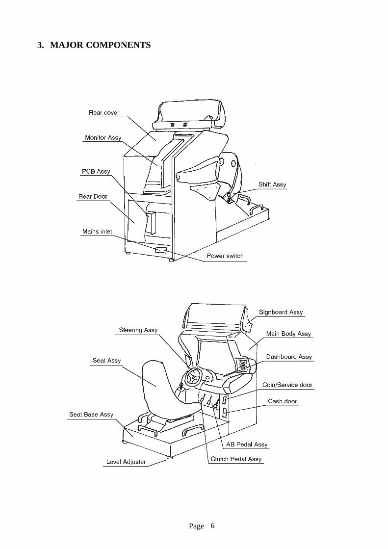
3. MAJOR COMPONENTS
Page
4. INSTALL ATION
Locate the two connection plates, 16 (M10x30 ) hex head bolts, 16 M10 springwashers
and 16 M10 flat washers.
4-1 Connecting the Main Body Assy and the Base Assy
1. Place the main body Assy and the base Assy in the installation site.
2. Connect the connectors of the main body Assy to that of the base Assy.
3. Fix the main body Assy to the base Assy with two connection plates and sixteenhexagonal bolts (M10 x 30), spring washers and flat washers.
4.2 Adjusting the Level Adjustors
Adjust the level adjustors of the main body Assy and those of the base Assy (four eachfor the main body Assy and the base Assy) with a wrench (24mm) so that the castersare lifted from the floor surface by about 5mm. Then install the product stably andback up the lock nut to lock the adjuster.
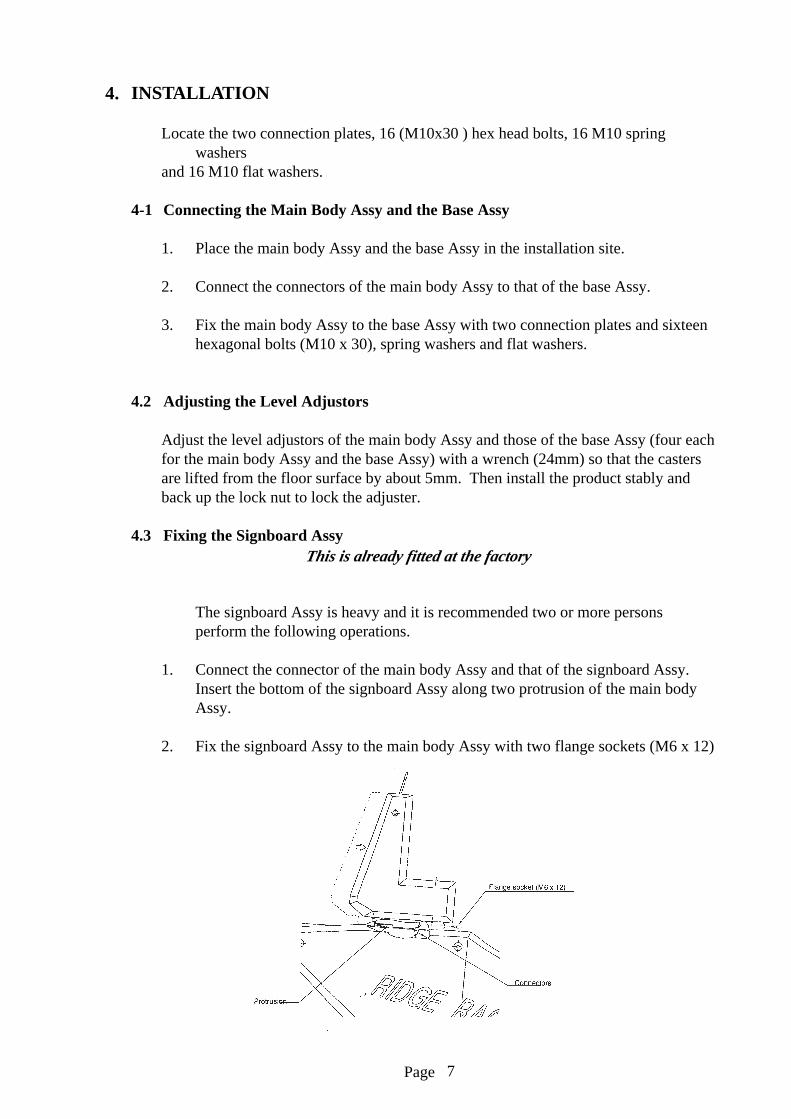
4.3 Fixing the Signboard Assy
The signboard Assy is heavy and it is recommended two or more personsperform the following operations.
1. Connect the connector of the main body Assy and that of the signboard Assy.Insert the bottom of the signboard Assy along two protrusion of the main bodyAssy.
2. Fix the signboard Assy to the main body Assy with two flange sockets (M6 x 12)
7
This is already fitted at the factory

Page
5. SIDE PANELS
5-1 Removing the Side Boards (R) and (L)
1. Remove eight torque bolts (M5 x 12), then the monitor panels (R) and (L).
2. Disconnect the connector and remove six hexagonal bolts (M6 X 30). Thenremove the side boards (R) and (L).
5-2 Removing the Dashboard Covers (R) and (L)
Remove five torque bolts (M5 X 12), then the dashboard covers (R) and (L).
8

Page
6. ADJUSTMENTS
6-1 Turning on the Power
After installing the product, turn on the power. The power switch is located above themains inlet on the rear of the main body.
6-2 Switches for Adjustments
Open the coin door to find the switches for adjustments.
1. Service switch.
Press this switch to increase the number of credits without incrementing the coincounter.
2. Test switch.
Set this switch to “ON” to enter test mode.You can change the game fee and so on, and perform various tests in Test mode.
(See “6-3 Test Mode” on page 10).
9

Page
6-3 Test Mode
1. Open the coin door, then set the test switch to “ON”. The “Menu Screen” appearson the monitor display.
2. Select the item to be tested by turning the steering wheel right or left. The colourof the item you selected changes.
3. Step on the accelerator pedal to display the menu of the selected item. To return tothe “Menu Screen”, step on the brake pedal (step on both the brake and clutchpedals on the Switch Test Screen).
4. When the test finishes, set the test switch to “OFF” to return to the Game Screen.
The Test switch must always be “OFF” during normal game mode.
MENU
COIN OPTION S (1) For setting the price of play (See 6-3-1)
GAME OPTION S (2) For setting the game options (See 6-3-2)
BOARD TEST (3) For testing the game PCB
SWITCH TEST (4) For testing switches (See 6-3-3)
SOUND TEST (5) For adjusting the sound volume (See 6-3-4)
MONITOR TEST (6) For monitor adjustments
ADS TEST (7) For displaying the game data collected
ABOUT (8) For restoring each setting to standard value
IN = STEP ON THE GAS
10

Page
6-3-1 Setting the Game Fee and So On (On the Coin Options Screen)
Select 1 “COIN OPTIONS” on the MenuScreen to set the game fee and so on.
Turn the steering wheel to select the itemto be changed, then step on theaccelerator pedal.
Turn the steering wheel again to changethe setting, then step on the acceleratorpedal (See table 1.)
Step on the brake pedal to return to theMenu Screen.
Note:Note:Note:Note:Note: The price of play adjustmentsare made on the credit boardand the coin options should beset as the following table.
Item Description
(a) Game fee Number of credit pulses necessary for game credit One to nine Set to 1
(b) Coin 1 mechanismNumber of credit pulses per coin One to nine Set to 1
(c) Coin 2 mechanism Not Used One to nine
(d) Bonus The extra credit given as a bonus when the specifiednumber of coins are inserted
One credit per one coinThree credits per ninecoins Set to NONE
(e) Free play Free play started by stepping on the accelerator OFF/ON set to OFF
COIN OPTIONS
GAME COST
2 COINS 1 CREDIT (a)
COIN 1 MECH VALUE
1 COIN COUNT AS 1 COIN (b)
COIN 2 MECH VALUE
1 COIN COUNT AS 1 COIN (c)
BONUS FOR QUANTITY BUY-IN
NONE (d)
FREE PLAY
OFF (e)
EXIT = STEP ON THE BRAKE
11

Page
6-3-2 Changing the Game Settings (on the Game Options Screen)
Select 2 “GAME OPTIONS”then change the game options.
Turn the steering wheel to selectthe item to be changed then stepon the accelerator pedal.
Turn the steering wheel again tochange the setting, then step onthe accelerator pedal(see table 2).
Step on the brake pedal to returnto the Menu Screen.
GAME OPTIONS
(DEFAULT IN GREEN)
GAME DIFFICULTY TIME EXTEND
NOVICE D ** ** ** (a)
ADVANCED D ** ** ** (b)
EXPERT D ** ** ** ** (c)
T. T. D ** ** ** ** (d)
LAP
NOVICE 2 (e)
ADVANCED 3 (f)
EXPERT 3 (g)
T. T. 3 (h)
SPEED KM/H (i)
SOUND IN ATTRACT
ON (j)
EXIT = STEP ON THE BRAKE
Item Description Factory setting
(a) Play time for the novice level A (shortest) to H (longest) D
(b) Play time time for the advanced levelA (shortest) to H (longest) D
(c) Play time for the expert level A (shortest) to H (longest) D
(d) Play time for the time trial game A (shortest) to H (longest) D
(e) Laps for the novice level 2 to 5 2
(f) Laps for the advanced level 2 to 5 3
(g) Laps for the expert level 2 to 5 3
(h) Laps for the time trial game 2 to 5 3
(i) Unit of speed KM/H (kilometer)MPH (Mile)
Set for country of use
(j) Attract sound ON/OFF ON
Settings of the Game Options Screen
12

Page
SWITCH TEST
DIP SW2 12345678 (a) Option switch (SW2 on the CPU)
SW3 12345678 (b) Option switch (SW3 on the CPU)
STEERING *0000 (c) Steering
GAS *0000 (d) Accelerator
BRAKE *0000 (e) Brake
CLUTCH OFF (f) Clutch
SHIFT N SWITCH 1 OFF (g) Shift
SWITCH 2 OFF
SWITCH 3 OFF
SWITCH 4 OFF
SERVICE OFF (h) Service switch
COIN 1 OFF (i) Coin 1 switch
COIN 2 OFF (j) Coin 2 switch
EXIT = STEP ON THE BRAKEAND CLUTCH
6-3-3 Switch TestSelect 3 “SWITCH TEST” to display the following screen.
a. The status of the option switch SW2 on the game PCB (CPU-PCB) is indicatedhere.
b. The status of the option switch SW3 on the game PCB (CPU-PCB) is indicatedhere.The SW2 or SW3 switch is set to ON when the corresponding number is red.
c. When you turn the steering wheel to the right, the number increments. Whenturning it to the left, the number decrements.
d. When you step on the accelerator pedal, the number increments.e. When you step on the brake pedal, the number increments. An approximate value
of “0000” appears on the item c, d or e respectively when you locate the steeringwheel in the middle and when the accelerator and brake pedals are released. (Evenif the least digit of the number changes, the game is operating normally). “OK”appears to the right of the number when the accelerator and brake pedals aredepressed.
f. "ON" appears when you depress the clutch pedal.g. The position of the shift (1 to 6, N) and the status of four switches are indicated
here.When you move the shift lever forwards, the switch 1 is set to ON. When youmove it backwards, the switch 2 is set to ON. When you move it to the leftdirection, the switch 3 is set to “ON”. When you move it to the right direction,the switch 4 is set to ON.
h. ”ON” appears when you press the service switch inside the coin door.i. "ON" appears when you operate the coin 1 switch.j. Not used.
To return to the Menu Screen, step on both the brake pedal
13

Page
6-3-4 Sound Test (Adjusting the Sound Volume)
Select “SOUND TEST” on the menu screen to adjust the sound volume. Thefollowing screen appears.
Use the steering wheel to select the item to be changed. Step on the acceleratorand the item selected will stop flashing. Use the steering to adjust the level. Stepon the accelerator when the desired setting is reached and the item will startflashing. The steering can now select another item.
The sound volume can be adjusted in 64 steps between 00 (minimum) to 3F(maximum). The factory setting is “3F”. (i.e. Loudest)
When you select (c) and step on the accelerator pedal, sound is produced the leftspeaker, then the right speaker. Step on the brake pedal to return to the MenuScreen.
The volume controls on the service bracket enable the seat volume to be reducedfrom the main volume.
SOUND TEST
VOLUME(L) 3F (a) Sound volume for left speakers
VOLUME(R) 3F (b) Sound volume for right speakers
STEREO CHECK (c) Stereo checking function
SONG 00
EXIT=STEP ON THE BRAKE
14
Page
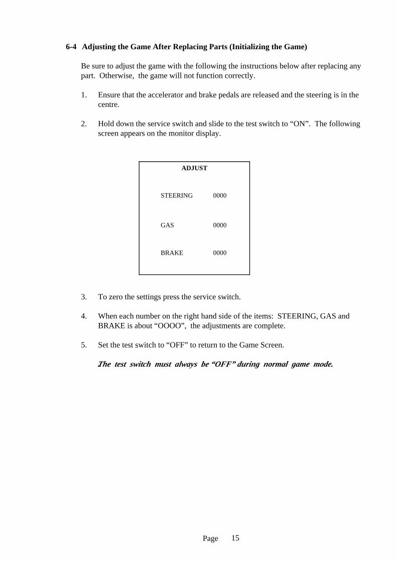
6-4 Adjusting the Game After Replacing Parts (Initializing the Game)
Be sure to adjust the game with the following the instructions below after replacing anypart. Otherwise, the game will not function correctly.
1. Ensure that the accelerator and brake pedals are released and the steering is in thecentre.
2. Hold down the service switch and slide to the test switch to “ON”. The followingscreen appears on the monitor display.
3. To zero the settings press the service switch.
4. When each number on the right hand side of the items: STEERING, GAS andBRAKE is about “OOOO”, the adjustments are complete.
5. Set the test switch to “OFF” to return to the Game Screen.
.The test switch must always be “OFF” during normal game mode.
ADJUST
STEERING 0000
GAS 0000
BRAKE 0000
15

Page
7. HOW TO PLAY
• This is the car race game.
• Players can enjoy virtual driving with a clutch and shift lever (Automatic setting isalso selectable).
• Four difficulties are provided: NOVICE, INTERMEDIATE, ADVANCED andTT (Time Trial) and two types of operations can be selected use of clutch and shiftlever or automatic.
(Outline of a Game)
• When a player drives a car the specified number laps within the given time, he orshe finishes the race, the ranking, lap time and total time are displayed and thegame is over.
• If the remaining time becomes “O” before a player finishes the race, the game isover.
(Starting a Game)
• Insert coins, then select the difficulty.Turn the steering wheel to select the difficulty from NOVICE, INTERMEDIATE,ADVANCED and TT, then step on the accelerator pedal to set it.
• Select the operation type: clutch and shift lever or automatic in the same manneras above.
• If a player does not select the above items within 10 seconds, the game sets itschoices by itself.
(Difference of the Difficulty Levels)
• When a player selects the NOVICE level, he or she drives a car on the MAINCOURSE at a low speed. This is the player’s car vs. computer driven cars racegame.
• When a player selects the INTERMEDIATE level, he or she drives a car on theMAIN COURSE at a high speed. This is the player’s car vs. computer-driven carsrace game.
• When a player selects the ADVANCED level, he or she drives a car on theMAIN COURSE and a TECHNICAL BRANCH at a high speed. This is theplayer’s car vs. computer-driven cars race game.
• When a player selects the TT level, he or she drives a car on the MAIN COURSEand the TECHNICAL BRANCH at a higher speed than that of the ADVANCEDlevel. This is the player’s car vs. a computer-driven car time trial race. When aplayer clocks a good time, they can record their name.
16

Page
88888 DDDDAAIAILAI LY MAINTENY MAINTE NANCEANCE
8-1 Removing the Game Printed Circuit Board (PCB)
1. Remove the backdoor,
2. Remove twoassembling bolts (M6X 30), then pull outthe power controlpanel about 25cm.(Note: if you pull itout too much, it willbe detached).
3. Disconnect twoconnectors on the EMIboard, then removesix cup screws (M4 X10) from the shieldcase door. (Do notlose internal washers).
4. Take care not todamage the connectorsbetween the EMIboard and the mainPCB to remove theshield case door, thentake out the main pcb.
5. Remove two cupscrews (M4 X 10)from the I/O door.(Note: Do not removeother screws).
6. Remove the I/O door,then disconnect fourconnectors of the I/OPCB.
7. Take out the I/O PCB.
17

Page
8-2 Removing the Shield Case
1. Perform Steps (1) and (2) described in Section 8-1.
2. Disconnect the connector of the AC Fan.
3. Remove two cup screw (M5 X 14) then take out the shield case.
8-3 Removing the Power Control Panel
1 Perform steps 1, 2, 5 and 6 described in Section 8-1.
2. Disconnect two connectors of the EMI board, remove a cup screw (M4 X 10)from the shield case door, then remove the ground terminal. (Note: do not losethe internal washer).
3. Disconnect the connectors connecting the power control panel and the main bodyassy: one connector on the right side and two connectors on the left side thenremove the power control panel.
8-4 Signboard Assy
8-4-1 Replacing the Fluorescent Lamp
1. Remove five torque bolts (M5 X 12) from the signboard cover.
2. Disconnect two connectors of the flashlight, then remove the signboard cover.
3. Pull out the fluorescent lamp cover, then disconnect the ground terminal andthe
connector connected to the main body assy. (Note: do not lose the internalwasher).
4. Pull out the fluorescent lamp fixing plate, then replace the fluorescent lamp(32W) with a new one.
18

Page
8-5 Dashboard Assy (Replacing the Fluorescent Lamp)
1. Remove five torque bolts (M5 x 12) located on the right side of the dashboard,then the dashboard cover (R).
2. Remove one cup screw (M5 X 12) and disconnect one connector. Then pull outthe FL bracket. To perform this operation, keep the right side of the main body320cm distance from another machine.
3. Replace the fluorescent lamp (15W) with a new one.
8-6 AB Pedal Assy (Replacing the Control)
1. Remove four hex head bolts (M6x20) and withdraw the assy forward .
2. Loosen the quadrant gear clamp screw and remove the quadrant gear.
3. Loosen the gear grub screw and remove the gear.
4. Replace the control potentiometer.
Note: When re-assemblinga. Ensure that the potentiometer locating tag is engaged in the mounting plate
cutout.b. Turn the potentiometer shaft almost fully clockwise before engaging the
quadrant gear.
19
Page
8-7 Clutch Pedal Assy (Replacing the Micro Switch)
1. Remove four hex head bolts (M6x20) and withdraw the assy forwards.
2. Replace the micro switch.
8-8 Steering Assy
8-8-1 Replacing the control
1. Remove four button head screws (M5x12), two on the steering column and twoon the underside front. Loosen three button head screws (M5x12), from theunderside rear, and remove the under cover vac-form.
2. Disconnect the four way connector.
3. Remove four hex head bolts (M10x20), two either side of the steering box assy.
4. Remove two hex head bolts (M10x20) under the steering column.
Warning: The steering assy is heavy and will drop when the two hex head boltsare removed, be ready to lower the assy.
5. Loosen the grub screw on the gear and remove the gear.
6. Replace the control potentiometer.
Note: When replacing the control potentiometer ensure that the locating tag of thepotentiomer is located in the hole in the mounting bracket and the pot shaft is atits mid travel before tightening the gear grub screw.
7. Re-initialize the game (See 6-4 Adjusting the Game - page 15) before the gameis played.
8-8-2 Replacing The Steering Wheel
1. Remove the centre cover of the steering wheel.
2. Remove three socket button heads (M6x16)
3. Pull of the steering wheel, then replace it with a new one.
20

Page
8-9 Gear Shift Assy (removing)
1. Remove six button head screws (M6x16) and remove the boot cover plate.
2. Remove twelve button head screws (M6x16) and remove the shifter cover plate.
3. Disconnect the six way connector.
4. Remove four hex head bolts (M6x20) retaining the shifter base plate to the housingassy and remove the assy.
8-10 Replacing the Speaker
1. Remove eight torque bolts (M5 X 12) located on the side of the main body, thenthe monitor panel (R) or monitor panel (L).
2. Ensure the correct colour wire is re-connected to each speaker terminal whenreplacing speaker.
21

Page
8-11Replacing the Monitor
The monitor weighs approximately 60 kgs and it is recommended THAT ATLEAST TWO PEOPLE remove the monitor.
1. Remove 14 torque bolts (M6 X 16), then the rear cover.
2. Disconnect two connectors.
3. Remove two hexagonal bolts (M6 X 20), then take out the monitor from the mainassy as indicated by the arrow mark.
4. Replace the monitor with a new one.
5. To replace the rear cover, hook the stud bolt of the rear cover to the hole of themain body assy, then fix the rear cover to the main body assy with fourteen torquebolts (M6 X 16).
22
Page
9. PAARTS LIST
CABINET
DESCRIPTION PART No
Monitor 33" Hantarex Polo 84000015
Speaker 4 1/2" 20w (with shield can) 62000006
Speaker - Piezo Horn 62000046
Accelerator/Brake Pedal Assy 88800021
Accelerator/Brake Control Pot (5k) 76000652
Clutch Pedal Assy 88800032
Steering Assy (340 degrees) 88800045
Steering Control Pot (5k) 76000652
Power Supply Assy - 5v/30amp 83000004
Schaffner Mains Filter Input Assy 66000016
Fan 67000015
Fluorescent Tube 18" 64500000
Choke 15w 63300000
100 Ohm 10w W/W Volume Control 76000164
M16 Adjustable Foot 88300079
75mm Castor 59000005
SEAT & BASE ASSY
DESCRIPTION PART No
Seat - (black) 88300673
Seat Slider Mechanism 88300680
Speaker 4 1/2" 20w 62000006
Speaker Cover Plate (Left) 88300603
Speaker Cover Plate (Right) 88300604
6 Speed Gear Shift Assy 88300672
Gear Shift Leather Boot 88300683
Bull Bar (Polished S/Steel) 88300678
M16 Adjustable Foot 88300079
75mm Castor 59000005
23

Page
DECALS
DESCRIPTION PART No
Side Speaker Cover-Ridge Racer (Left) 40000187
Side Speaker Cover-Ridge Racer (Right) 40000193
Gear Shift Upper (A) 40000188
Gear Shift Lower (B) 40000189
Seat Back-Ridge Racer/Twin Turbo 40000190
Namco 40000191
Twin Turbo 40000192
VAC-FORM PLASTICS
DESCRIPTION PART No
Side Speaker Cover (Left) 88300716
Side Speaker Cover (Right) 88300717
Screen Surround 88300720
Dashboard 88300722
Dashboard Under Cover 88300723
Dashboard Side Closing Cover (Left) 88300724
Dashboard Side Closing Cover (Right) 88300725
Steering Closing Cover 88300726
Header End Closing Cover (Left) 88300729
Header End Closing Cover (Right) 88300730
ACRYLICS
DESCRIPTION PART No
Screen Top Hood (Smoked) 88300705
Speedo Front Cover 88300727
Battery/Oil Front Cover 88300728
Speedo Printed Polycarbonate 33000115
Battery/Oil Printed Polycarbonate 33000116
Ridge Racer Top Flash 30000058
24