RICOH Ri 3000 Ri 6000 User Manual - anajet.com · For safe and correct use, be sure to read the...
173
For safe and correct use, be sure to read the Safety Information in Safety Information and Quick Installation Guide before using the machine. Version 1.0 RICOH Ri 3000 Ri 6000 USER MANUAL
-
Upload
truongdung -
Category
Documents
-
view
215 -
download
0
Transcript of RICOH Ri 3000 Ri 6000 User Manual - anajet.com · For safe and correct use, be sure to read the...

For safe and correct use, be sure to read the Safety Information in Safety Information and Quick Installation Guide before using the machine.
Version 1.0
RICOH
Ri 3000
Ri 6000
USER MANUAL

RICOH Ri 3000 & RICOH Ri 6000 Direct to Garment Printer User Manual
Copyright © 2017 AnaJet, Inc.

3
Table of Contents
How to Read Manuals .................................................................................................................................... 7
Safety Symbols for This Machine ......................................................................................................... 8
Safety Information for This Machine ................................................................................................... 9 Safety during Operation .................................................................................................................................. 9
Safety Precautions to Be Followed .................................................................................................... 10 Environments where the machine can be used ........................................................................................... 10 Handling power cords and power plugs ....................................................................................................... 10 Power source ................................................................................................................................................ 11 Handling the main machine .......................................................................................................................... 12 Handling the machine's interior.................................................................................................................... 13 Handling the machine's supplies .................................................................................................................. 14 Adjustment ................................................................................................................................................... 15 Removing the Fabric ..................................................................................................................................... 15 Maintenance (Cleaning the Units and Disposing of Waste Ink) ................................................................... 15
Safety Labels of This Machine............................................................................................................ 16 Front .............................................................................................................................................................. 16 Back ............................................................................................................................................................... 16 Machine’s Interior ......................................................................................................................................... 17
Symbols for Power Switch ................................................................................................................. 20 Symbols for power switch that are used for this machine are as follows: ................................................... 20
User Notes ........................................................................................................................................ 21
Laws and Regulations ........................................................................................................................ 22 Legal Prohibition ........................................................................................................................................... 22
Chapter 1: Product Information ............................................................................................... 24 1: Printer Specifications ................................................................................................................................ 24 2: Operation Environment Requirements ..................................................................................................... 28 3: System Requirements ............................................................................................................................... 29 4: Computer Interface Requirements ........................................................................................................... 29 5: Consumables ............................................................................................................................................. 29 6: Customer Training Checklist ..................................................................................................................... 30
Chapter 2: Startup of a New Printer ........................................................................................ 31 1: Unpacking the Printer ............................................................................................................................... 31 2: What’s in the Box ...................................................................................................................................... 32 3: What Else is Needed .................................................................................................................................. 33 4: Setting up the Printer ................................................................................................................................ 33 5: Before Filling the Printer with Ink ............................................................................................................. 37 6: Filling the Printer with Ink ......................................................................................................................... 37
4
7: Performing a Nozzle Check ........................................................................................................................ 41 8: Printer Software Program Requirements ................................................................................................. 43 9: Adding a new printer to AnaRIP ................................................................................................................ 44
10: Choosing Ink Sets .................................................................................................................................... 44
Chapter 3: Printer Controls ..................................................................................................... 46 1: Power Switches ......................................................................................................................................... 46 2: Control Panel............................................................................................................................................. 46 3: Buttons ...................................................................................................................................................... 48
Chapter 4: Printer Operation .................................................................................................. 49 1: First Time Start up Sequence .................................................................................................................... 49 2: Power up Sequence .................................................................................................................................. 49 3: Power down Sequence ............................................................................................................................. 49 4: Moving Print Table .................................................................................................................................... 50 5: Adjustment of Print Table ......................................................................................................................... 50 6: Safety Warnings ........................................................................................................................................ 52
Chapter 5: Printer Settings ....................................................................................................... 59 1: Select Printer settings................................................................................................................................ 59 2: Language ................................................................................................................................................... 59 3: Pre-Print Checks ........................................................................................................................................ 60 4: Wipe After Number of Prints .................................................................................................................... 61 5: Cap Head Delay ......................................................................................................................................... 62 8: Network Connection ................................................................................................................................. 66 9: Printer Number ......................................................................................................................................... 68 10: Set Time Zone ......................................................................................................................................... 69 11: Print Counters ......................................................................................................................................... 69
Chapter 6: Light Garment Printing Process ............................................................................... 71 1: AnaRIP Raster Image Processor ................................................................................................................ 71 2: Printer Performance ................................................................................................................................. 71 3: Using the RICOH Ri 3000 and RICOH Ri 6000 AnaRIP Program for Printing Light Garments.................... 71 4: AnaRIP Advanced features ........................................................................................................................ 83 5: Loading Garments on the Print Table ....................................................................................................... 87 6: Removing Garments from the Print Table ................................................................................................ 88 7: Set the Image with Heat ........................................................................................................................... 88
Chapter 7: Printing on Dark Garments ...................................................................................... 90 1: Basic Dark Garment Printing Process ........................................................................................................ 90 2: Maintenance of White Ink ........................................................................................................................ 91 3: Scheduled Maintenance ........................................................................................................................... 92 4: Pre-treatment of Dark Colored Garments ................................................................................................ 92 5: Dark Garment Ri 3000 or Ri 6000 AnaRIP Settings ................................................................................... 94 6: Set the Image with Heat Treatment ....................................................................................................... 105
5
7: Dark Garment Washing ........................................................................................................................... 106
Chapter 8: Hot Folders ........................................................................................................... 107 1: Creating a template ................................................................................................................................ 107 2: Establish Hot Folder Location ................................................................................................................. 108 3: Define Holder Folder Settings ................................................................................................................. 108
Chapter 9: Maintenance and Transportation .......................................................................... 113 1: Technical Notes on White Ink Maintenance ........................................................................................... 114 2: Maintenance Schedule ........................................................................................................................... 115 3: Required Maintenance ........................................................................................................................... 116 4: Ink Levels and Cart Replacement ............................................................................................................ 124 5: Switching from Ink to Cleaning Solution Using the Startup Fill Function ............................................... 128 6: Waste Ink Tank and Drip Absorbers........................................................................................................ 129 7: Changing Fan Filters ................................................................................................................................ 134 8: Cleaning the Printer ................................................................................................................................ 134 9: Transporting the Printer ......................................................................................................................... 135
Chapter 10: Firmware Updates .............................................................................................. 138 1: Firmware Menu....................................................................................................................................... 138 2: Major Control Firmware Updates ........................................................................................................... 138 3: Minor Control Firmware Updates ........................................................................................................... 141 4: Board Firmware Updates ........................................................................................................................ 143
Chapter 11: Troubleshooting ................................................................................................. 146 1: The Print Engine Does Not Turn On ........................................................................................................ 146 2: The Printer Does Not Print Anything ...................................................................................................... 146 3: Black Screen ............................................................................................................................................ 147 4: Startup Application Error ........................................................................................................................ 148 5: Platform did not lower upon startup ...................................................................................................... 148 6: Home Table Time Out ............................................................................................................................. 149 7: Home Carriage Time Out ........................................................................................................................ 150 8: Platform Did Not Lower/Engage ............................................................................................................. 151 9: Failed to Calibrate Head Drive Board Voltage ........................................................................................ 152 10: Horizontal Banding ................................................................................................................................ 154 11: Incorrect or Missing Colors ................................................................................................................... 154 12: Prints are Faint and there are Gaps ...................................................................................................... 155 13: Blurry or Smeared Prints ....................................................................................................................... 155 14: Color Image is Printing in Black Only .................................................................................................... 155 15: Printing is Too Slow ............................................................................................................................... 156 16: When the <PRINT> Button is Pressed, the Obstruction Sensor is Triggered ........................................ 156 17: Print Table Does Not Travel All the Way to the Front or Rear .............................................................. 156 18: The Print Head Nozzles Get Clogged Too Often ................................................................................... 157 19: Information to Provide Technical Support ............................................................................................ 158 20: How to Get Additional Help .................................................................................................................. 160

6
Appendices: .......................................................................................................................... 161 1: Appendix 1 .............................................................................................................................................. 161 2: Appendix 2 .............................................................................................................................................. 167 3: Appendix 3 .............................................................................................................................................. 168 4. Appendix 4 ………………………………………………………………………………………………………………………………………. 169

7
How to Read the Manuals Disclaimer
Contents of this manual are subject to change without prior notice. To the maximum extent permitted by applicable laws, in no event will the manufacturer be liable for any damages whatsoever arising out of failures of this machine, losses of the registered data, or the use or non-use of this product and operation manuals provided with it. Make sure that you always copy or have backups of the data registered in this machine. Documents or data might be erased due to your operational errors or malfunctions of the machine. In no event will the manufacturer be responsible for any documents created by you using this machine or any results from the data executed by you.
Notes
The manufacturer shall not be responsible for any damage or expense that might result from the use of parts other than genuine parts from the manufacturer with your products. For good output quality, the manufacturer recommends that you use genuine ink from the manufacturer. Some illustrations in this manual might be slightly different from the machine. Certain options might not be available in some countries. For details, please contact your local dealer. Depending on which country you are in, certain units may be optional. For details, please contact your local dealer.

8
Safety Symbols for This Machine The meanings of the safety symbols for this machine are as follows:
Caution
Prohibition
General mandatory action sign
Do not touch
Caution, risk of having hands or arms caught
Caution, risk of electric shock
Caution, hot surface
Warning; Laser beam

9
Safety Information for This Machine Safety during operation
In this manual, the following important symbols are used:
Indicates a potentially hazardous situation which, if instructions are not followed, could result in death or serious injury.
Indicates a potentially hazardous situation which, if instructions are not followed, may result in minor or moderate injury or damage to property.

10
Safety Precautions to Be Followed Environments where the machine can be used
• Do not use flammable sprays or solvents in the vicinity of this machine. Also, avoid placing these items in the vicinity of this machine. Doing so could result in fire or electric shock.
• Do not place vases, plant pots, cups, toiletries, medicines, small metal objects, or containers holding water or any other liquids, on or close to this machine. Fire or electric shock could result from spillage or if such objects or substances fall inside this machine.
• Keep the machine away from humidity and dust. Otherwise a fire or an electric shock might occur.
• Do not place the machine on an unstable or tilted surface. If it topples over, an injury might occur.
• Do not obstruct the machine's vents. Doing so risks fire caused by overheated internal components.
• Make sure the room where you are using the machine is well ventilated and spacious. Good ventilation is especially important when the machine is used heavily. When you detect an odd smell, sufficiently ventilate and circulate the air in the room.
• Keep children away from the machine. Otherwise, their hands or fingers may be caught in the gap and injury may result.
• Keep people other than operators away from the machine. Otherwise, their hands or fingers may be caught in the gap and injury may result. • Use at an altitude of 2000 m or less. There is a possibility of electric shock, electric leakage, and fire if it is used in an environment exceeding 2000 m altitude.
Handling power cords and power plugs
• Do not use any power sources other than those that match the specifications shown in this manual. Doing so could result in fire or electric shock.
• Do not use any frequencies other than those that match the specifications shown. Doing so could result in fire or electric shock.
• Do not use multi-socket adaptors. Doing so could result in fire or electric shock.
• Do not use extension cords. Doing so could result in fire or electric shock.
• Do not use power cords that are damaged, broken, or modified. Also, do not use power cords that have been trapped under heavy objects, pulled hard, or bent severely. Doing so could result in fire or electric shock.

11
• It is dangerous to handle the power cord plug with wet hands. Doing so could result in electric shock.
• Touching the prongs of the power cable's plug with anything metallic constitutes a fire and electric shock hazard.
• The supplied power cord is for use with this machine only. Do not use it with other appliances. Doing so could result in fire or electric shock.
• If the power cord is damaged and its inner wires are exposed or broken, contact your service representative for a replacement. Use of damaged power cords could result in fire or electric shock.
• Be sure to disconnect the plug from the wall outlet at least once a year and check for the following: •There are burn marks on the plug. •The prongs on the plug are deformed. •The power cord's inner wires are exposed, broken, etc. •The power cord's coating has a crack or dent. •When bending the power cord, the power turns off and on. •Part of the power cord becomes hot. •The power cord is damaged.
•If any of the above conditions exist, do not use the plug and consult your dealer or service representative. Use of the plug could result in fire or electric shock.
• When disconnecting the power cord from the wall outlet, always pull the plug, not the cord. Pulling the cord can damage the power cord. Use of damaged power cords could result in fire or electric shock. • Be sure to push the plug of the power cord fully into the wall outlet. Partially inserted plugs create an unstable connection that can result in unsafe buildup of heat.
• Be sure to disconnect the plug from the wall outlet and clean the prongs and the area around the prongs at least once a year. Allowing dust to build up on the plug constitutes a fire hazard.
• When performing maintenance on the machine, always turn off the power switch on rear of the machine.
Power source
• 100-240V, 2A, 50/60Hz Voltage must not fluctuate more than 10%. Please be sure to connect the power cable to a power source as above. For users in Norway, this product is also designed for an IT power distribution system with phase-to-phase voltage of 230V. Confirm that the wall outlet is near the machine and freely accessible, so that in event of an emergency, it can be unplugged easily.

12
Handling the main machine
• Keep infants away from polythene materials (bags, etc.) used to wrap the machine and its accessories. Suffocation may result if polythene materials are brought into contact with the mouth or nose.
• If the machine emits smoke or odors, or if it behaves unusually, you must turn off its power immediately. After turning off the power, be sure to disconnect the power cord plug from the wall outlet. Then contact your service representative and report the problem. Do not use the machine. Doing so could result in fire or electric shock.
• If metal objects, or water or other fluids fall inside this machine, you must turn off its power immediately. After turning off the power, be sure to disconnect the power cord plug from the wall outlet. Then contact your service representative and report the problem. Do not use the machine. Doing so could result in fire or electric shock.
• Do not touch this machine if a lightning strike occurs in the immediate vicinity. Doing so could result in electric shock.
• The machine weights around 81.6 kg (180 lb.).
• Four or more people are required to lift the printer. When moving the printer, lift it slowly so that you do not strain yourself. Lifting the printer forcibly or handling it roughly to drop it will risk injury.
• Unplug the power cord from the wall outlet before you move the machine. While moving the machine, take care that the power cord is not damaged under the machine. Failing to take these precautions could result in fire or electric shock.
• Before installing or removing options, always turn off the power switch on rear of the machine and allow time for the main unit to fully cool. Failing to take these precautions could result in burns. • Before opening the top cover, please turn off the power switch on the back of the machine and open it. Opening the cover without turning off the power may cause the machine to operate and cause injury.
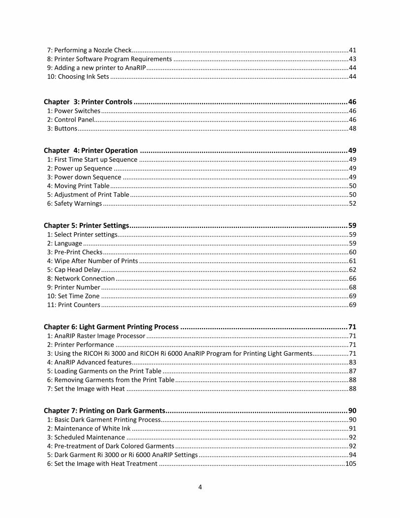
• When opening and closing the top cover, be sure to hold the handle. Be careful so that your hand or any other part of your body is not caught with the top cover.
13
• After opening the top cover, use the prop to keep the cover raised so that it does not close unexpectedly. Otherwise, your hand caught may be caught between the cover and the machine. • Make sure that the top cover is closed, and then turn on the power switch on the back of the machine. Before closing the cover, turning on the power may cause the machine to operate and cause injury.
• Before turning on the power for the first time, remove the 2 retainer brackets that have labels affixed. Turning on the power without removing them may cause the machine to malfunction.
• Follow the procedures in the user's manual for maintenance and securely install parts and covers. Failure to do reliable work may cause injury or malfunction.
Handling the machine's interior
• Do not remove any covers or screws other than those explicitly mentioned in USER MANUAL.
• Before you remove the cover, turn off the power switch on rear of the machine. Removing the cover with the power on or removing parts other than those explicitly referred to could result in electric shock.

14
• Do not attempt to disassemble or modify this machine. Doing so risks burns and electric shock.
• Do not open the cover while the machine is operating. Doing so might cause your hand or fingers to get trapped in the machine, and an injury might occur.
Handling the machine's supplies
• Keep infants away from polythene materials (bags, etc.) used to wrap options and cartridges/bottles for ink, cleaning solution, HV storage solution, and pretreatment liquid. Suffocation may result if polythene materials are brought into contact with the mouth or nose.
• When swallowing or inhaling ink, cleaning solution, HV storage solution or pretreatment liquid, or when getting them in the eye, follow the guidance in the appropriate safety data sheet (SDS). Download the SDS from the AnaJet website at http://anajet.com/technical-documentation
• Place ink, cleaning solution, HV storage solution, and pretreatment liquid in a cool, well-ventilated place out of the reach of children.
• Keep waste ink, containers for ink, cleaning solution, HV storage solution, and pretreatment liquid, and components that have been in contact with ink out of the reach of children.
• When handling ink, cleaning solution, HV storage solution, or pretreatment liquid, avoid getting anything on your clothing. If you do, wash the stained area with cold water.
• When replacing the cartridge for ink, cleaning solution, HV storage solution, or pretreatment liquid, avoid getting anything on your clothing. If you do, wash the stained area with cold water.
• When replacing the cartridge for ink, cleaning solution, HV storage solution, or pretreatment liquid, avoid getting anything on your skin. If you do, wash the affected area thoroughly with soap and water.
• When removing the cartridge for ink, cleaning solution, HV storage solution, or pretreatment liquid, avoid putting your hand near the location in which the cartridge is installed (such as the ink supply nozzle and its surrounding areas). If you get anything on your hands, wash them thoroughly with soap and water.
• The ink cartridge surface may have ink on it, so be careful to avoid ink stains.
• Do not disassemble the cartridge for ink, cleaning solution, HV storage solution, or pretreatment liquid. Doing so could leave ink stains or cleaning solution on your hands and fingers.
• When shaking the cartridge for ink, cleaning solution, HV storage solution, or pretreatment liquid, be careful about safety of your surroundings and ink stains. Otherwise, injury or stains on household
15
items may result.
Adjustment
• When moving the Print Table, be careful so that your hands or fingers are caught with it. Otherwise, injury may result.
• When adjusting the machine feet to level the machine, be careful so that your hand is not caught between the machine foot and stand. If it is caught, injury may result.
Removing the Fabric
• When removing the fabric, be careful so that your hand or any other part of your body does not come in contact with ink. If your skin comes in contact with ink, wash the affected area thoroughly with soap and water. If your clothing comes into contact with ink, wash the stained area with cold water.
Maintenance (Cleaning the Units and Disposing of Waste Ink)
• When maintenance is performed, the carriage may move while the top cover is open. Do not touch the carriage while it is moving. Touching it may result in injury.
• Be sure to wear commercially available goggles and gloves when performing the following maintenance:
• Cleaning the Maintenance Station and nozzle plates • Cleaning and replacing the wiper blade • Cleaning the left and right ink drip foam trays • Replacing the drip pan foam • Disposing of the waste ink (in the waste ink tank and auxiliary waste ink tank) • Cartridge replacement
• When using a flat head screwdriver, be careful so that the tip of the flat head screwdriver does not hurt you.

16
Safety Labels of This Machine This section explains the machine’s safety information labels.
Positions of WARNING and CAUTION labels
This machine has labels for WARNING and CAUTION at the positions shown below. For safety, please follow the instructions and handle the machine as indicated.
Front
1. Do not reach far inside the unit. Moving parts inside may cause injury. 2. Do not reach far inside the unit. Moving parts inside may cause injury. 3. Keep your eyes away from the laser aperture so that the laser does not shine directly into your
eyes. The laser can cause injury.
Back
4. This printer uses a class 2 laser radiation. Regarding the position, refer to 3. 5. This label is meant for customer engineers.
17
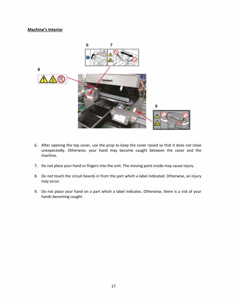
Machine’s Interior
6. After opening the top cover, use the prop to keep the cover raised so that it does not close unexpectedly. Otherwise, your hand may become caught between the cover and the machine.
7. Do not place your hand or fingers into the unit. The moving parts inside may cause injury.
8. Do not touch the circuit boards in from the part which a label indicated. Otherwise, an injury may occur.
9. Do not place your hand on a part which a label indicates. Otherwise, there is a risk of your
hands becoming caught.

18
10. Remove the part indicated by the label before the machine is first turned on. Otherwise, there is the risk of breakage of the machine.
11. Do not touch the circuit board. Doing so could result in injury.

19
12. Be careful so that your hand is not caught with the main scanning pulley. If it is caught, injury may result.

20
Symbols for Power Switch Symbols for power switch that are used for this machine are as follows:
I: POWER ON
O: POWER OFF

21
User Notes
• During operation, do not touch the carriage. Do not put your hand into the gap between the top cover and Print Table. • For information about how to use the heat press device, see the manual. • When removing the fabric, be careful so that your clothing is not stained with ink. If your clothing comes into contact with ink, wash the stained area with cold water.

22
Other Information for This Machine
Laws and Regulations
Legal Prohibition Do not copy or print any item for which reproduction is prohibited by law. Copying or printing the following items is generally prohibited by local law: bank notes, revenue stamps, bonds, stock certificates, bank drafts, checks, passports, driver's licenses. The preceding list is meant as a guide only and is not inclusive. We assume no responsibility for its completeness or accuracy. If you have any questions concerning the legality of copying or printing certain items, consult with your legal advisor.
FCC Statement (USA): • Note: This equipment has been tested and found to comply with the limits for a Class A digital device, pursuant to Part 15 of the FCC Rules. These limits are designed to provide reasonable protection against harmful interference when the equipment is operated in a commercial environment. This equipment generates, uses, and can radiate radio frequency energy and, if not installed and used in accordance with the instruction manual, may cause harmful interference to radio communications. Operation of this equipment in a residential area is likely to cause harmful interference in which case the user will be required to correct the interference at his own expense. • Caution: Changes or modifications not expressly approved by the party responsible for compliance could void the user’s authority to operate the equipment. • Caution: Properly shielded and grounded cables and connectors must be used for connections to host computer (and/or peripheral) in order to meet FCC emission limits.
User Information on Electrical and Electronic Equipment: Caution: An AC adapter with ferrite core must be used for RF interference suppression.
Note to Users in California (USA): • Perchlorate Material - special handling may apply. See: www.dtsc.ca.gov/hazardouswaste/perchlorate
Laser Emitter Warning and Laser Aperture Warning • The Obstruction Sensor detects any obstruction on the Print Table, such as wrinkles on the shirts, which can damage the print heads. On the left-hand side of the printer, there is an Obstruction Laser Diode, which generates the laser. On the right-hand side, there is the Obstruction Laser Sensor.
Laser (North America): • This equipment complies with 21 CFR 1040.10 and 1040.11 except for deviations pursuant to Laser Notice No. 50, dated June 24, 2007 for class II laser product. This equipment contains one AlGaInP laser diode, 660 nanometer wavelength. The beam divergence angle is 21 degrees (minimum) and 29 degrees (maximum) in the vertical direction, and 7 degrees (minimum) and 11 degrees (maximum) in the horizontal direction, and laser beams are generated in ContinuousWave (CW) mode. The maximum output power of the light source is 1 milliwatt.

23
• WARNING: Although the laser used in the Ri 3000 and Ri 6000 printer is low power, exercise care so that laser does not shine directly into the eyes. The laser can cause injury. • CAUTION—Use of controls or adjustments or performance of procedures other than those specified herein may result in hazardous radiation exposure. • Mangled Hand Warning: Keep body parts away from gears and moving parts.

24
Laser (others) • This machine complies with the requirements of IEC 60825-1:2014 (EN 60825-1:2014) for class 2 laser product. This equipment contains one AlGaInP laser diode, 660 nanometer wavelength. The beam divergence angle is 21 degrees (minimum) and 29 degrees (maximum) in the vertical direction, and 7 degrees (minimum) and 11 degrees (maximum) in the horizontal direction, and laser beams are generated in Continuous Wave (CW) mode. The maximum output power of the light source is 1 milliwatt.
• WARNING: Although the laser used in the Ri 3000 and Ri 6000 printer is low power, exercise care so that laser does not shine directly into the eyes. The laser can cause injury. • CAUTION—Use of controls or adjustments or performance of procedures other than those specified herein may result in hazardous radiation exposure. • Mangled Hand Warning: Keep body parts away from gears and moving parts.

25
Noise Levels
The following table quantifies the noise levels for various of RICOH Ri 3000/6000 system.
Component Noise level
RICOH Ri 3000/6000 62 dB(A)

26

24
Chapter 1: Product Information
Congratulations on your purchase of a RICOH Ri 3000 or RICOH Ri 6000 Garment Printer. Ricoh is committed to providing our customers with the best in training materials and through this User Manual it is our aim to get you up and printing in the shortest time possible. For additional training, we recommend you contact your RICOH Ri 3000/ Ri 6000 dealer for additional training courses.
1: Printer Specifications
Printing Method: Direct to Garment Inkjet Printing Print Head Technology: Print on demand piezoelectric inkjet
Printing Resolution: 600x300, 600x600, 1200x600 dpi
Print Channels: 6 (Cyan, Magenta, Yellow, Black and 2 channels of White)
Printable area: 14” x 18” (35.6cm x 45.7cm) Main Print Table
Mechanical: Garment loading method: Ink Supply: Printer Dimensions: Adjustment: Weight:
Hooped Print Table Garment Path: Shuttling Print Table Sealed Ink Cartridges 19.8” x 42.3” x 44” (50.3 cmx 107.4 cm x 111.8 cm) Table Height Up to 2.30” (5.84 cm) Approximately 180 lbs. (81.6 Kg)
Electrical: Input Voltage Range: Input Frequency: Range Power Consumption: Altitude:
100 – 240V 50/60 Hz 2.0 A (maximum) 0.65 A (idling) 2000m or below

25
CAUTION
FCC Statement (USA): Note: This equipment has been tested and found to comply with the limits for a Class A digital device, pursuant to Part 15 of the FCC Rules. These limits are designed to provide reasonable protection against harmful interference when the equipment is operated in a commercial environment. This equipment generates, uses, and can radiate radio frequency energy and, if not installed and used in accordance with the instruction manual, may cause harmful interference to radio communications. Operation of this equipment in a residential area is likely to cause harmful interference in which case the user will be required to correct the interference at his own expense.
Caution: Changes or modifications not expressly approved by the party responsible for compliance could void the user’s authority to operate the equipment.
Caution: Properly shielded and grounded cables and connectors must be used for connections to host computer (and/or peripheral) in order to meet FCC emission limits.
User Information on Electrical and Electronic Equipment: Caution: An AC adapter with ferrite core must be used for RF interference suppression.
Laser (US): This equipment complies with the requirements of IEC60825-1:2014 for class 2 laser product. The beam divergence angle is 0.6 mRad (Half Angle). This equipment contains a 650 nanometer wavelength. The maximum output power of the light source is 1 milliwatt.
Note to Users in California (USA): Perchlorate Material. Special handling may apply. See www.dtsc.ca.gov/hazardouswaste/perchlorate
Warning for Electrical and Electronic Equipment (For EU countries only): This equipment is compliant with Class A of CISPR 32. In a residential environment, this equipment may cause radio interference.
1) Properly shielded and grounded cables and connectors must be used for connections to a host
computer (and/or peripheral) in order to meet emission limits. 2) An AC adapter with a ferrite core must be used for RF interference suppression.
Laser (EU): This equipment complies with the requirements of IEC60825-1:2014 for class 2 laser product. The beam divergence angle is 0.6 mRad (Half Angle). This equipment contains a 650 nanometer wavelength. The maximum output power of the light source is 1 milliwatt.
EMC Directive: Warning on Class A Product This equipment is compliant with Class A of CISPR 32. In a residential environment this equipment may cause radio interference. As this machine is not a household appliance, it does not conform to ErP Directive 2009/125/EC which was revised in 2013.

26
Users in the countries where this symbol shown in this section has been specified in national law on collection and treatment of E-waste Our products contain high quality components and are designed to facilitate recycling. Our products or product packaging are marked with the symbol below.
The symbol indicates that the product must not be treated as municipal waste. It must be disposed of separately via the appropriate return and collection systems available. By following these instructions you ensure that this product is treated correctly and help to reduce potential impacts on the environment and human health, which could otherwise result from inappropriate handling. Recycling of products helps to conserve natural resources and protect the environment. For more detailed information on collection and recycling systems for this product, please contact the shop where you purchased it, your local dealer or sales/service representatives All Other Users If you wish to discard this product, please contact your local authorities, the shop where you bought this product, your local dealer or sales/service representatives. For Turkey only
User Information on Electrical & Electronic Equipment
27
CE Marking Traceability Information (For EU Countries Only) Manufacturer: RICOH Company, Ltd.
3-6 , Nakamagome 1-chome, Ohtaku, Tokyo 143-8555, Japan
Importer: Ricoh Europe PLC 20 Triton Street, London. NW1 3BF, United Kingdom RICOH Company, Ltd.
Note for the Battery and/or Accumulator Symbol (For EU countries only)
In accordance with the Battery Directive 2006/66/EC Article 20 Information for end-users Annex ll, the above symbol is printed on batteries and accumulators. This symbol means that in the European Union, used batteries and accumulators should be disposed of separately from your household waste. In the EU, there are separate collection systems for not only used electrical and products but also batteries and accumulators. Please dispose of them correctly at your local community waste collection/recycling centre.

28
2: Operation Environment Requirements Please establish these requirements in your print area before setting up your printer and filling it with ink.
Temperature (printer): Operation (with inks loaded): 59°F to 90 °F (15°C to 32°C) Storage (without ink): 14° F to 104° F (-10°C to 40°F) Temperature (storing inks): 41°F to 90°F (5°C to 32°C)
Humidity (printer): Operation (with inks loaded): 45% to 80% RH, non-condensing. Storage (without ink): 20% to 85% RH, non- condensing.
Figure 1.2-1: Electronic It is crucial for trouble-free printer operation that the Relative Humidity (RH) requirement is met at all times when the printer is loaded with ink. If the environment is below the specified Relative Humidity the ink will dry more quickly at the Print Head causing nozzles to become clogged. Keep an electronic hygrometer (humidity gauge) near the printer at all times to ensure that the relative humidity is maintained. Electronic hygrometers are available in electronic stores, department stores or hardware stores, but be sure that they are of a high quality be sure to have them calibrated regularly. If relative humidity falls below 45% at any time, it will be necessary to use a high-powered non-misting humidifier to increase the humidity in the immediate area of the printer. Also, keep in mind that it will be much easier to control the environment in a small area rather than a large one.
29
3: System Requirements
RICOH Ri 3000/Ri 6000 printers are designed to be used with a PC running Windows Vista, Windows 7, Windows 8 or Windows 10 Operating System. The programs needed to run your Ri 3000 or Ri 6000 printer do not work on an Apple computer unless it is running Windows emulation software such as Parallels, Bootcamp or other software that allow one to run the Windows Operating System on Apple computers. A PC with an operating system other than Windows Vista, Windows 7, Windows 8 or Windows 10 will not be able to run the printer software.
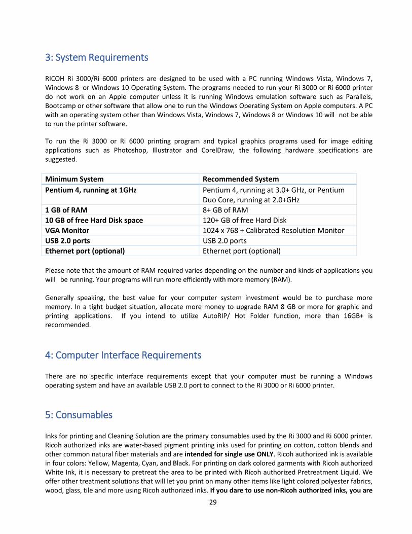
To run the Ri 3000 or Ri 6000 printing program and typical graphics programs used for image editing applications such as Photoshop, Illustrator and CorelDraw, the following hardware specifications are suggested.
Minimum System Recommended System
Pentium 4, running at 1GHz Pentium 4, running at 3.0+ GHz, or Pentium Duo Core, running at 2.0+GHz
1 GB of RAM 8+ GB of RAM
10 GB of free Hard Disk space 120+ GB of free Hard Disk
VGA Monitor 1024 x 768 + Calibrated Resolution Monitor
USB 2.0 ports USB 2.0 ports
Ethernet port (optional) Ethernet port (optional)
Please note that the amount of RAM required varies depending on the number and kinds of applications you will be running. Your programs will run more efficiently with more memory (RAM). Generally speaking, the best value for your computer system investment would be to purchase more memory. In a tight budget situation, allocate more money to upgrade RAM 8 GB or more for graphic and printing applications. If you intend to utilize AutoRIP/ Hot Folder function, more than 16GB+ is recommended.
4: Computer Interface Requirements There are no specific interface requirements except that your computer must be running a Windows operating system and have an available USB 2.0 port to connect to the Ri 3000 or Ri 6000 printer.
5: Consumables Inks for printing and Cleaning Solution are the primary consumables used by the Ri 3000 and Ri 6000 printer. Ricoh authorized inks are water-based pigment printing inks used for printing on cotton, cotton blends and other common natural fiber materials and are intended for single use ONLY. Ricoh authorized ink is available in four colors: Yellow, Magenta, Cyan, and Black. For printing on dark colored garments with Ricoh authorized White Ink, it is necessary to pretreat the area to be printed with Ricoh authorized Pretreatment Liquid. We offer other treatment solutions that will let you print on many other items like light colored polyester fabrics, wood, glass, tile and more using Ricoh authorized inks. If you dare to use non-Ricoh authorized inks, you are

30
responsible for any result including damage arising out of your use of non-Ricoh authorized inks.
This User Manual provides general guidelines for using Ricoh authorized Ink. But there is a great deal of variation on the way digital inks interact with a specific textile material. The ink performance can vary significantly depending on the exact chemical characteristics of the textile and the way the fabric is woven or knitted. It is not uncommon for garment manufacturers to treat the fabric with special chemicals for various reasons. Thus, the performance of Ricoh approved inks on a specific fabric may vary significantly and the ink may not work for a given garment type. Ricoh does not guarantee its inks will work on a specific garment. If you are printing on an unfamiliar fabric, it is always necessary to test your results before beginning a production run. See Appendix 1 for the list of consumables. Keep a reasonable quantity of consumables on hand so as not to run out, but do not stock up too many ink cartridges as they have expiration dates. Use all ink cartridges before the indicated expiration dates. Generally, Ricoh authorized CMYK inks expire 12 months after the manufacturing date that is printed on the cartridge. Ricoh authorized White expires in 6 months from the manufacturing date. Cleaning Solutions and Pretreatment Liquid have much longer shelf lives, typically 3 years. Do not use expired inks as they tend to clump and will clog the ink delivery system and Print Head, thus damaging the printer. It is recommended to agitate stock inks on a weekly basis.
6: Customer Training Checklist Through the use of this manual you will become acquainted with all of the items in the list below to complete your training
Correct operating environment for trouble-free operation. Leveling the Printer and proper Printer Placement for good print quality. Loading Garments on the Print Table and Placement of Garment on Print Table in relation to the
Graphics program / Print Preview. Obstruction (laser) Sensor. Print Head Cleaning, Nozzle Check, Print Nozzle Purge, etc. Understanding your Printer Settings The need for Regular Printer Maintenance and Cleaning. Accessing Maintenance Station / Moving the Carriage off the Maintenance Station. Cleaning Maintenance Station, Nozzle Plate Edges, etc. Printer Environment, Humidity and Temperature. Waste Ink Drain operation. Control Panel Functions and Navigation. Proper Black Shirt Pretreatment. Printing white shirts / printing black shirts. Proper use of RIP program. Installing ink cartridges, low ink warnings, replacing ink cartridges. How to ship the printer. Charge cleaning solution, use original shipping box and pallet.
31
Chapter 2: Startup of a New Printer
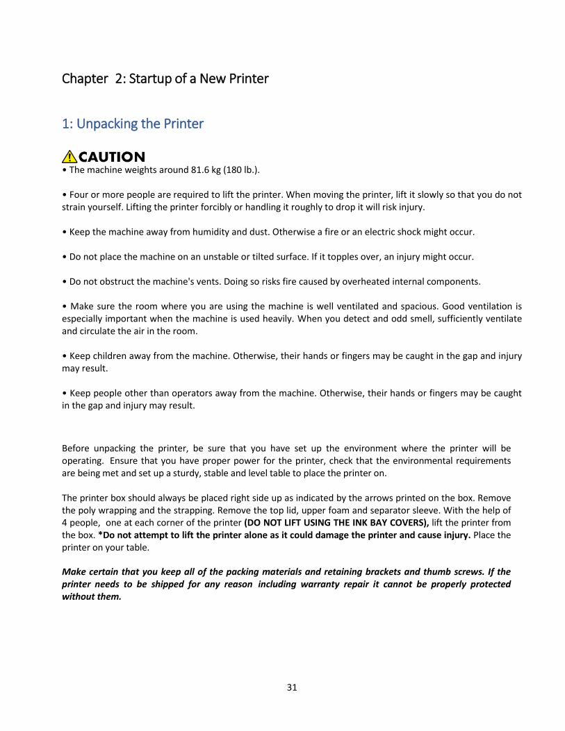
1: Unpacking the Printer
• The machine weights around 81.6 kg (180 lb.). • Four or more people are required to lift the printer. When moving the printer, lift it slowly so that you do not strain yourself. Lifting the printer forcibly or handling it roughly to drop it will risk injury. • Keep the machine away from humidity and dust. Otherwise a fire or an electric shock might occur. • Do not place the machine on an unstable or tilted surface. If it topples over, an injury might occur. • Do not obstruct the machine's vents. Doing so risks fire caused by overheated internal components. • Make sure the room where you are using the machine is well ventilated and spacious. Good ventilation is especially important when the machine is used heavily. When you detect and odd smell, sufficiently ventilate and circulate the air in the room. • Keep children away from the machine. Otherwise, their hands or fingers may be caught in the gap and injury may result. • Keep people other than operators away from the machine. Otherwise, their hands or fingers may be caught in the gap and injury may result.
Before unpacking the printer, be sure that you have set up the environment where the printer will be operating. Ensure that you have proper power for the printer, check that the environmental requirements are being met and set up a sturdy, stable and level table to place the printer on. The printer box should always be placed right side up as indicated by the arrows printed on the box. Remove the poly wrapping and the strapping. Remove the top lid, upper foam and separator sleeve. With the help of 4 people, one at each corner of the printer (DO NOT LIFT USING THE INK BAY COVERS), lift the printer from the box. *Do not attempt to lift the printer alone as it could damage the printer and cause injury. Place the printer on your table.
Make certain that you keep all of the packing materials and retaining brackets and thumb screws. If the printer needs to be shipped for any reason including warranty repair it cannot be properly protected without them.

32
2: What’s in the Box For machines sold in the US: o 1 RICOH Ri 3000/Ri 6000 Printer o 1 Power cord (US) o 1 USB cable o RICOH Ri 3000/Ri 6000 Safety Information and Quick Installation guide for your printer o Cleaning Applicators (1 pack) o Wiper Blade (set of 2) o Lint-free wipes (pack of 30) o 50 sheets of Soft Touch Heat Press Paper o 1 syringe kit for maintenance procedures o 1 Black Pretreated T-Shirts o 1 bubble level tool for leveling the printer o 1 squeegee o 1 RICOH Ri 3000/Ri 6000 front printer feet o 1 Set 200 mL CMYKWW Ricoh authorized ink o 1 gallon Ricoh authorized Pretreatment o 1 4 oz. bottle of Ricoh authorized cleaning solution for maintenance o 1 set of polyethylene gloves for maintenance
For machines sold outside of the US: o 1 RICOH Ri 3000/Ri 6000 Printer o 1 Power cord (US) o 1 USB cable o RICOH Ri 3000/Ri 6000 Safety Information and Quick Installation guide for your printer o Cleaning Applicators (1 pack) o Wiper Blade (set of 2) o Lint-free wipes (pack of 30) o 50 sheets of Soft Touch Heat Press Paper o 1 syringe kit for maintenance procedures o 1 Black Pretreated T-Shirts o 1 bubble level tool for leveling the printer o 1 squeegee o 1 RICOH Ri 3000/Ri 6000 front printer feet o 5 pairs of polythene gloves All items other than the printer are packaged in an Accessory Box inside the printer box. Keep all accessory items nearby for future use. (NOTE: This is the basic accessory kit included with all printers, your accessory kit may include additional items.)

33
3: What Else is Needed
The following items will also be needed for your RICOH Ri 3000/Ri 6000 printer operation: 1. Electronic hygrometer/thermometer (to monitor the relative humidity of the room the printer
is operating in). 2. PC computer with Vista, Windows 7, Windows 8 or Windows 10 operating system. 3. Graphics software installed in the PC, such as Photoshop, CorelDraw, Photoshop Elements
or Illustrator. 4. Heat press or textile oven (for heat curing of the ink). 5. Adequate supply of garments to print. 6. Paper towels. 7. Standard 8.5” x 11” copying or printing paper. 8. High Volume Low Pressure (HVLP) electric sprayer or other type of sprayer for
applying pretreatment for dark garments.
4: Setting up the Printer
Figure 2.4-1 Retainer Brackets
Removing retaining brackets It is very important that the printer be operated on a stable, sturdy and level table. Ensure that the table is sturdy enough so the printer does not shake or vibrate during operation. Operating the printer on an unstable, uneven or slanted surface will cause poor print quality and could damage the printer. Unlatch the Top Cover using the key provided and turning counter-clockwise. Hold the key in this position and lift the cover. Locate the Table and Carriage Retainers. (See figure 2.4-1) Remove thumb screws holding the Table and Carriage Retainer in position. (See figure 2.4-1). Keep the Retainers and 3 Thumb Screws for future use for printer shipment. Now you can move the Print Table manually back and forward to make certain that the Print Table is free. Take a moment to look at all internal mechanisms and verify that nothing has been damaged during shipping.
34
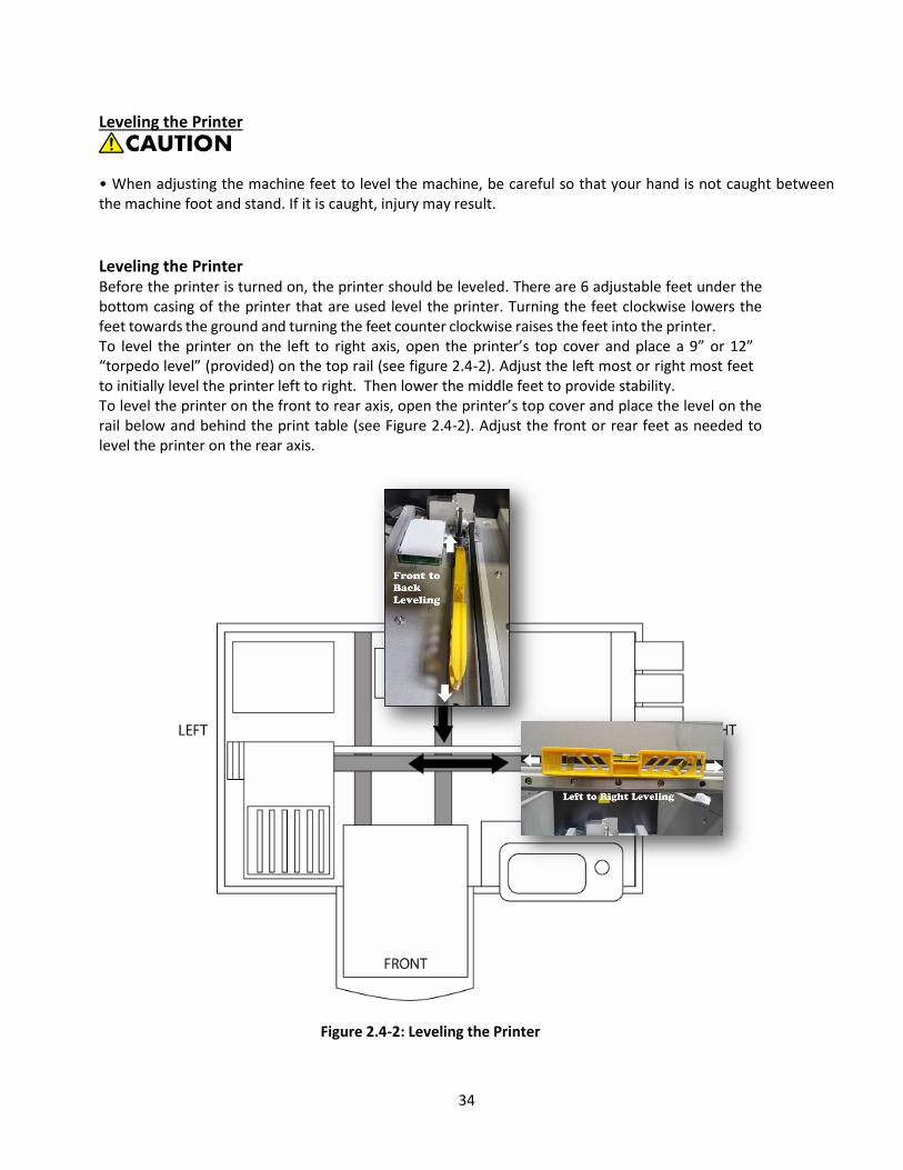
Leveling the Printer
• When adjusting the machine feet to level the machine, be careful so that your hand is not caught between the machine foot and stand. If it is caught, injury may result.
Leveling the Printer Before the printer is turned on, the printer should be leveled. There are 6 adjustable feet under the bottom casing of the printer that are used level the printer. Turning the feet clockwise lowers the feet towards the ground and turning the feet counter clockwise raises the feet into the printer. To level the printer on the left to right axis, open the printer’s top cover and place a 9” or 12” “torpedo level” (provided) on the top rail (see figure 2.4-2). Adjust the left most or right most feet to initially level the printer left to right. Then lower the middle feet to provide stability. To level the printer on the front to rear axis, open the printer’s top cover and place the level on the rail below and behind the print table (see Figure 2.4-2). Adjust the front or rear feet as needed to level the printer on the rear axis.
Figure 2.4-2: Leveling the Printer

35
Connecting Cable Connections
• Do not use any power sources other than those that match the specifications shown in this manual. Doing so could result in fire or electric shock. • Do not use any frequencies other than those that match the specifications shown. Doing so could result in fire or electric shock. • Do not use multi-socket adaptors. Doing so could result in fire or electric shock. • Do not use extension cords. Doing so could result in fire or electric shock. • Do not use power cords that are damaged, broken, or modified. Also, do not use power cords that have been trapped under heavy objects, pulled hard, or bent severely. Doing so could result in fire or electric shock. • It is dangerous to handle the power cord plug with wet hands. Doing so could result in electric shock. • Touching the prongs of the power cable's plug with anything metallic constitutes a fire and electric shock hazard. • The supplied power cord is for use with this machine only. Do not use it with other appliances. Doing so could result in fire or electric shock. • If the power cord is damaged and its inner wires are exposed or broken, contact your service representative for a replacement. Use of damaged power cords could result in fire or electric shock.
• Be sure to disconnect the plug from the wall outlet at least once a year and check for the following: • There are burn marks on the plug. • The prongs on the plug are deformed. • The power cord's inner wires are exposed, broken, etc. • The power cord's coating has a crack or dent. • When bending the power cord, the power turns off and on. • Part of the power cord becomes hot. • The power cord is damaged.
• If any of the above conditions exist, do not use the plug and consult your dealer or service representative. Use of the plug could result in fire or electric shock.
• When disconnecting the power cord from the wall outlet, always pull the plug, not the cord. Pulling the cord can damage the power cord. Use of damaged power cords could result in fire or electric shock. • Be sure to push the plug of the power cord fully into the wall outlet. Partially inserted plugs create an unstable connection that can result in unsafe buildup of heat. • Be sure to disconnect the plug from the wall outlet and clean the prongs and the area around the prongs

36
at least once a year. Allowing dust to build up on the plug constitutes a fire hazard. • When performing maintenance on the machine, always turn off the power switch on rear of the machine.
Power source • 100-240V, 2A, 50/60Hz
Voltage must not fluctuate more than 10%. Please be sure to connect the power cable to a power source as above. Confirm that the wall outlet is near the machine and freely accessible, so that in event of an emergency, it can be unplugged easily.
Plug in the provided power cord to a surge protector connected to a wall outlet. Ri 3000/Ri 6000 printer power supplies will accommodate voltages ranging from 100 to 2450 volts. Next, plug the power cord into the power entry module in the rear of the printer. Do not plug the USB Cable into the printer or PC at this time.
The USB ports located on the back and front panels of the printer are to be used with USB flash drives ONLY!
The USB B port is for connecting the printer to a PC
Figure 2.4-3: Plus in the Power Cord and USB Cables
Turn on the power switch on the rear of the Power Entry Module; this will bring power into the printer’s power supply. Now press the large round <POWER> key on the front control panel. The printer control panel LCD display will light up and the printer is now fully powered on and able to do its automatic ink circulation and maintenance. (Please note due to this two-stage power on sequence that if the printer loses power due to an outage it will not fully power on when the electricity is restored.
If you are in an area where your electrical power is inconsistent you may want to invest in an Uninterruptible Power Supply (UPS) that will supply battery backup power to your printer during an electrical outage.

37
Figure 2.4-4: Splash Screen Figure 2.4-5: Printer LCD Display
5: Before Filling the Printer with Ink
Before we add ink to the printer we will to do a quick check to ensure that the printer is operating correctly. To do this we will power up the printer at the control panel and observer that following printer functions are done. After pressing the <POWER> key on the control panel, the control panel display will show the Ri 3000/Ri 6000 flash screen and then it will initialize and finish at the Jobs Screen. During this initialization observe the printer movement through the table opening. You should see the print carriage move to the right and then back to its home position and then the print table will move out to its load position.
STOP – If this is a new printer, contact your RICOH Ri 3000/Ri 6000 supplier before going any
further to schedule your setup and training session with your certified technician to complete the installation process. Download the User Manual and AnaRIP software at AnaJet.com/downloads
6: Filling the Printer with Ink
•Keep infants away from polythene materials (bags, etc.) used to wrap options and cartridges/bottles for ink, cleaning solution, HV storage solution, and pretreatment liquid. Suffocation may result if polythene materials are brought into contact with the mouth or nose.
• When swallowing or inhaling ink, cleaning solution, HV storage solution or pretreatment liquid, or when getting them in the eye, follow the guidance in the appropriate safety data sheet (SDS). Download the SDS from the AnaJet website at http://anajet.com/technical-documentation • Place ink, cleaning solution, HV storage solution, and pretreatment liquid in a cool, well-ventilated place out of the reach of children. • Keep waste ink, containers for ink, cleaning solution, HV storage solution, and pretreatment liquid, and
38
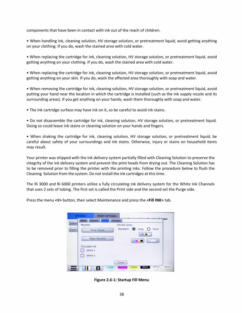
components that have been in contact with ink out of the reach of children. • When handling ink, cleaning solution, HV storage solution, or pretreatment liquid, avoid getting anything on your clothing. If you do, wash the stained area with cold water. • When replacing the cartridge for ink, cleaning solution, HV storage solution, or pretreatment liquid, avoid getting anything on your clothing. If you do, wash the stained area with cold water. • When replacing the cartridge for ink, cleaning solution, HV storage solution, or pretreatment liquid, avoid getting anything on your skin. If you do, wash the affected area thoroughly with soap and water. • When removing the cartridge for ink, cleaning solution, HV storage solution, or pretreatment liquid, avoid putting your hand near the location in which the cartridge is installed (such as the ink supply nozzle and its surrounding areas). If you get anything on your hands, wash them thoroughly with soap and water. • The ink cartridge surface may have ink on it, so be careful to avoid ink stains. • Do not disassemble the cartridge for ink, cleaning solution, HV storage solution, or pretreatment liquid. Doing so could leave ink stains or cleaning solution on your hands and fingers. • When shaking the cartridge for ink, cleaning solution, HV storage solution, or pretreatment liquid, be careful about safety of your surroundings and ink stains. Otherwise, injury or stains on household items may result. Your printer was shipped with the ink delivery system partially filled with Cleaning Solution to preserve the integrity of the ink delivery system and prevent the print heads from drying out. The Cleaning Solution has to be removed prior to filling the printer with the printing inks. Follow the procedure below to flush the Cleaning Solution from the system. Do not install the ink cartridges at this time.
The Ri 3000 and Ri 6000 printers utilize a fully circulating ink delivery system for the White Ink Channels that uses 2 sets of tubing. The first set is called the Print side and the second set the Purge side.
Press the menu <≡> button, then select Maintenance and press the <Fill INK> tab.
Figure 2.6-1: Startup Fill Menu

39
Figure 2.6-2: Countdown
Figure 2.6-3: Fill Print Lines Menu
Now Fill Ink Lines, select a duration time of long and press the button with all 6 channels. We will fill all 6 channels at once. When completed, select long again and select all 6 channels again. Verify the print lines have been cleared of Cleaning Solution, additional short fills may be necessary to flush out the tubes. Select CLOSE and the window will disappear.
Installing Ink Cartridges We will now install the ink cartridges. All Ricoh authorized inks are intended for single use ONLY. The ink cartridge bay is located on the right-hand side of the printer. For US machines, new printer is shipped with 6 Ricoh authorized ink cartridges: 1 of each color: cyan, yellow, magenta, black and 2 white. For machines outside the US, ink will be included in the accessory box.
Remove the cartridges from the box and protective bag and gently shake a few times before installing them into the ink bays. It is very important that the correct color ink cartridge gets installed in the correct bay as shown below in Figure 2.6-6.
If you install a cartridge in the wrong bay the Control Panel will indicate this with a Mismatch error on the Control Panel display, however, it can contaminate the ink delivery system.
40
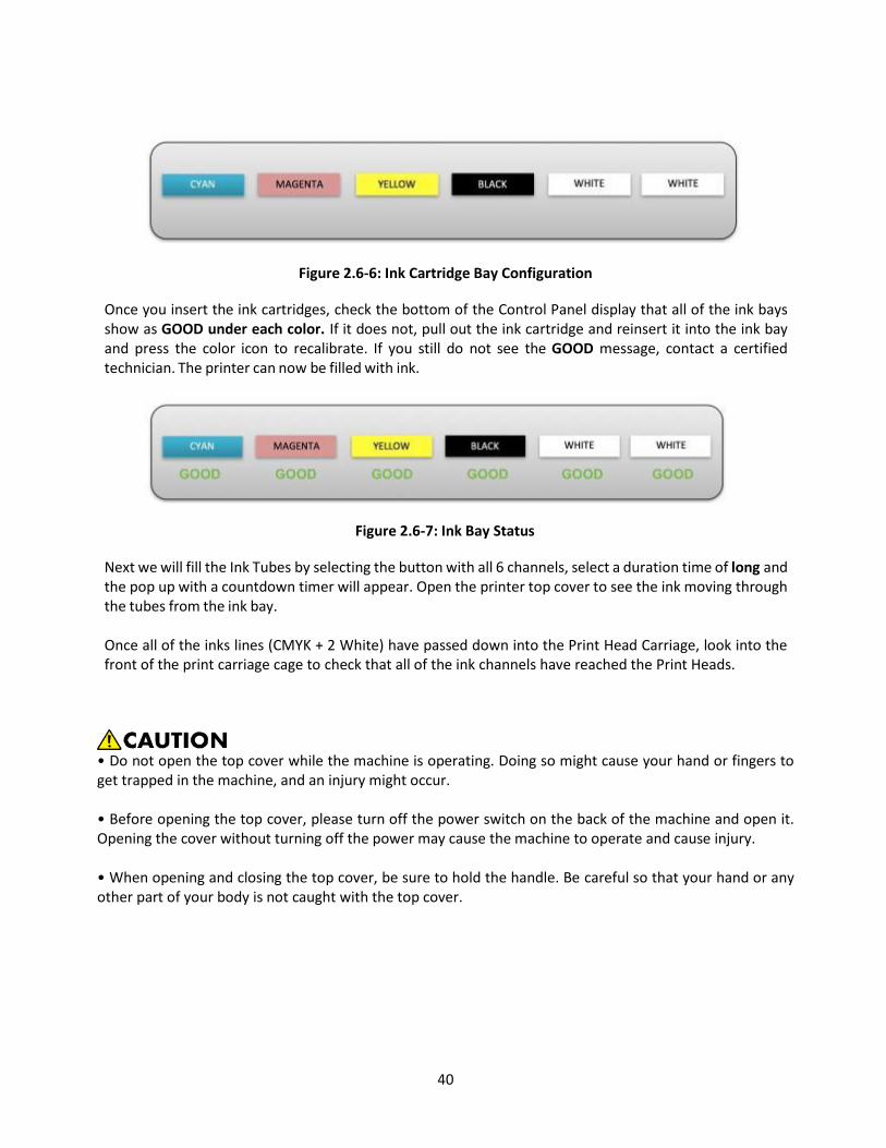
Figure 2.6-6: Ink Cartridge Bay Configuration
Once you insert the ink cartridges, check the bottom of the Control Panel display that all of the ink bays show as GOOD under each color. If it does not, pull out the ink cartridge and reinsert it into the ink bay and press the color icon to recalibrate. If you still do not see the GOOD message, contact a certified technician. The printer can now be filled with ink.
Figure 2.6-7: Ink Bay Status
Next we will fill the Ink Tubes by selecting the button with all 6 channels, select a duration time of long and the pop up with a countdown timer will appear. Open the printer top cover to see the ink moving through the tubes from the ink bay.
Once all of the inks lines (CMYK + 2 White) have passed down into the Print Head Carriage, look into the front of the print carriage cage to check that all of the ink channels have reached the Print Heads.
• Do not open the top cover while the machine is operating. Doing so might cause your hand or fingers to get trapped in the machine, and an injury might occur. • Before opening the top cover, please turn off the power switch on the back of the machine and open it. Opening the cover without turning off the power may cause the machine to operate and cause injury. • When opening and closing the top cover, be sure to hold the handle. Be careful so that your hand or any other part of your body is not caught with the top cover.

41
• After opening the top cover, use the prop to keep the cover raised so that it does not close unexpectedly. • Make sure that the top cover is closed, then turn on the power switch on the back of the machine. Before closing the cover, turning on the power may cause the machine to operate and cause injury. Otherwise, your hand caught may be caught between the cover and the machine. If not complete, repeat the fill procedure using the short time interval until all of the ink channels have reached the Print Heads and you see no gaps in the ink tubes. If not complete, repeat the fill procedure using the short time interval until all of the ink channels have reached the Print Heads and you see no gaps in the ink tubes.
Figure 2.6-8: Ink Line Filling Point
7: Performing a Nozzle Check
Now that the lines have been filled with ink you will need to perform a Nozzle
Check. First we need to set the table height by pressing the menu <≡> button and selecting Maintenance; then select the Motion tab and select Auto Adjust Height. This will lower the table, move it into the printer and raise it until it triggers the

42
obstruction sensor laser. It then slightly lowers the table to set the correct printing height. To print a Nozzle Check, press the <PRINT CHECK> button (the button which shows all 6 channels in the lower left - hand corner).
Figure 2.7-1: Motion Tab Figure 2.7-2: Print Head Nozzle Check
Position a sheet of letter sized paper on the lower right corner of the print table as shown on the display, (Note that the print table edge closest to you is the top and therefore the preview on the display will appear rotated 180°) and press the <PRINT CHECK> button. The print table will now move in and print the nozzle check.
If you have a Ri 3000 you will see one channel of each of your colors printed on the paper and one block from each of the whites printed on the table (See Figure 2.7-3 below). If you have an Ri 6000 you will see two channels of each color printed on the paper and four channels of white printed on the table.
Figure 2.7-3: Print Head Nozzle Check Example
If the Nozzle Check Pattern looks good, then you are finished with the initial printer setup. If it does not, you will to do a print head clean. This process is not uncommon when first filling the printer with ink. A Print Head Clean is performed from the Print Check menu. You will see the following menu of options.

43
Figure 2.7-4: Print Head Clean Menu
If your nozzle check only shows that the white ink channels are not firing fully then select Clean White Channels, indicated by the orange arrow. If you need to clean any of the CMYK channels, select the CMYK channel clean indicated by the green arrow. If you need to clean both CYMK and White channels, select the 6 channel clean indicated by the blue arrow.
When the clean is completed select Close and pop up will disappear.
You now need to perform another Nozzle Check to check the status of your print nozzles. If the check is still not good, repeat the Print Head Cleans until it is. If the Nozzle Check Pattern looks good, then you are finished with the initial printer setup.
8: Printer Software Program Requirements Once the ink cartridges are installed and ink flow has been established, it’s time to install the AnaRIP software onto the PC. Your PC must have Microsoft Windows Vista, Windows 7, Windows 8, or Windows 10 operating system, or on a MAC, some kind of Windows emulation must be running such as Parallels or Boot Camp. The computer also needs to have an USB 2.0 port.
AnaRIP Printer Software Program Download and Installation Prior to setting up your printer, you will need to download the latest version of AnaRIP software for your printer. You can find this software at www.AnaJet.com/downloads . Locate the latest version of AnaRIP for your specific printer. You will then be routed to a page with download and installation instructions. When the software is installed double click the AnaRIP icon to launch the software and then connect the printer to the computer using the provided USB cable. Do not use a USB cable longer than 10 feet or use an unpowered USB Hub since data transmission loss can occur. After the cable is installed place an image into the software by going to File and then Place an image.

44
9: Adding a new printer to AnaRIP
In order to utilize a connected printer via Ethernet or USB, new printers must be added via the Manage Printers in the View section of the RIP.
Figure 2.9-1: View Manage Printers
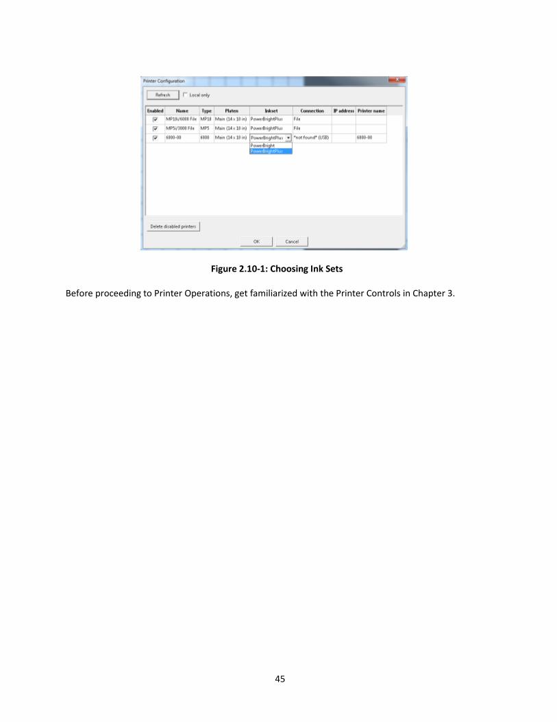
Figure 2.9-2: Printer Configuration 10: Choosing Ink Sets Under Manage Printers you can choose which ink set profiles you wish to use. PowerBright Plus ink set is designed to be optimized for Ricoh authorized Inks.
45
Figure 2.10-1: Choosing Ink Sets
Before proceeding to Printer Operations, get familiarized with the Printer Controls in Chapter 3.

46
Chapter 3: Printer Controls 1: Power Switches
The power is controlled by two switches: The main power switch and control panel <POWER> button. The main power switch is on the rear left side. Switch the power on.
2: Control Panel
The Ri 3000 and Ri 6000 Control Panel consists of a touch LCD display, a circular power/print button and a USB port on the right side. The control panel layout is shown below in (Figure 3.2-1).
Figure 3.2-1: Control Panel
When the main power switch is turned on, it powers the printer’s power supply control board. Now press the <POWER/PRINT> button to the right of the control panel, this fully powers up the printer. The control panel will display a splash screen and then the main menu.
To power down, simply press the Control Panel power key and then turn off the main power switch on the rear of the unit. If the carriage is not in home position over the maintenance station and the capping plate is not sealing against the nozzle plates, turn the unit back on to initialize the unit and then power down again. It is recommended that the printer is fully powered on (Back and front) at all

47
times, even when the printer is not used. Keeping the power on enables the printer to perform periodic minimal self-maintenance routines that help prevent the print head from drying out.

48
3: Buttons
The <POWER> button powers on the print engine. Make sure you have switched the Master Power Switch on the back of the printer first. Power button should glow with a blue light.
The <TABLE> button moves the Print Table back and forth. Pressing it while the Print Table is moving will stop the table. Pressing it again will move the table in the opposite direction. When the Print Table reaches the front or rear limit, the table will stop automatically.
The <PRINT> button initiates the printing operation of the job shown in the Current Job page display. The current print job usually is the last job sent from the computer, or selected from Jobs List, or loaded from USB drive. When the blue LED Print Ready lights up behind the <PRINT> button, the printer is ready to print. Press the <PRINT> button. The table will start moving into the printer to initiate printing operations.
The <PRINTCHECK> button invokes Nozzle Check Pattern operation and clean functions. The <PRINT> button must be pressed to start printing the Nozzle Check.
The AUTO Table Height Adjustment button allows you to adjust the height of the print table to accommodate different thicknesses of garments and substrates when the Print Menu is displayed. There is also a manual adjustment knob under the print table.
The<CANCEL> button is used to cancel an operation, usually the Print operation or Print Table movement.
The <CLOSE> button will close the Menu pop-up
The <MENU> button brings up the MAIN MENU page
The <MAINTENANCE> button found in the main menu screen opens up a maintenance functions popup to access the motion controls, print counters, ink fills and firmware updates.
The <SETTINGS> button found in the main menu screen opens up the printer settings popup to access the printer and system settings, jobs handling, pre-print checks and network settings.
The <DIAGNOSTICS> button found in the main menu screen opens up the printer settings popup to access to the exercise motion functions, print head settings and printer information.
The <ABOUT PRINTER> button found in the main menu screen opens up the printer settings popup to access the printer information.
The <POWER OFF> button found in the main menu screen will power the printer down. The printer can also be powered down by holding down the power/print button.
The <ADVANCED> button found on the main menu is activated by pressing the print button 8 times with the main menu open. This brings up the technical menu and is used to perform maintenance checks on the printer.

49
Chapter 4: Printer Operation 1: First Time Start up Sequence When you first setup the printer, please refer to the procedures in Chapter 2: Start Up of a New Printer.
2: Power up Sequence The power up sequence consists of two power switches. First turn on the main power switch on the rear of the printer. Next press the Control Panel <POWER> button to turn on the printer. A splash screen will appear on the display showing the Ricoh logo and the power up sequence will begin. The Print Table will move forward to the Load Position. When the power up sequence is properly completed, the following display (in Figure 4.2-1) will show in the LCD.
Figure 4.2-1: LCD When Power up Sequence is Complete
3: Power down Sequence The power down sequence is the reverse of the power up sequence. Make sure the Print Head Carriage is over the Maintenance Station. If it is not power the Printer off in the back and restart to return all components to home position. Power the printer down from the Control Panel power key and then the power switch located on the back. It is recommended that the printer be kept powered on at all times when ink is loaded in the system, even if the printer is not used, unless the printer is filled with cleaning solution and is in storage. Keeping the printer powered on prevents the Print Head from drying. A minimal amount of ink is used to keep the Print Head wet. If the Print Head dries up, the Head Cleaning operation to restore it will consume more ink than keeping the Print Head wet during idle times. In certain cases, the dried Print Head may not recover.
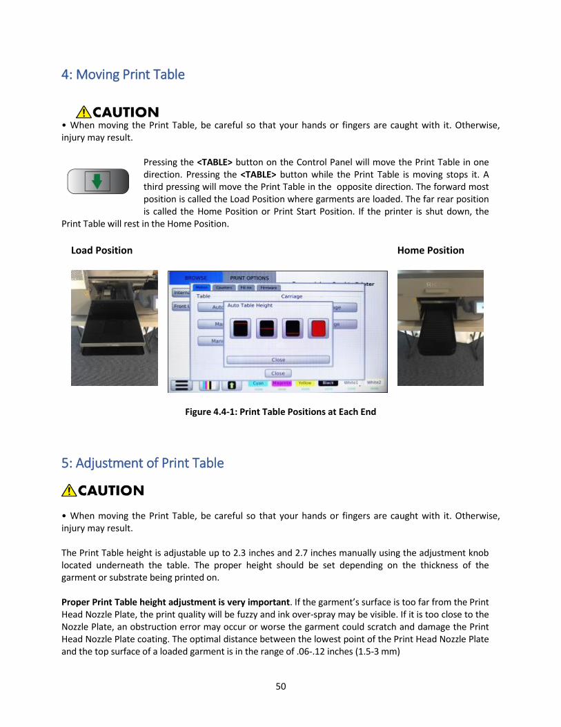
50
4: Moving Print Table
• When moving the Print Table, be careful so that your hands or fingers are caught with it. Otherwise, injury may result.
Pressing the <TABLE> button on the Control Panel will move the Print Table in one direction. Pressing the <TABLE> button while the Print Table is moving stops it. A third pressing will move the Print Table in the opposite direction. The forward most position is called the Load Position where garments are loaded. The far rear position is called the Home Position or Print Start Position. If the printer is shut down, the
Print Table will rest in the Home Position.
Load Position Home Position
Figure 4.4-1: Print Table Positions at Each End
5: Adjustment of Print Table
• When moving the Print Table, be careful so that your hands or fingers are caught with it. Otherwise, injury may result. The Print Table height is adjustable up to 2.3 inches and 2.7 inches manually using the adjustment knob located underneath the table. The proper height should be set depending on the thickness of the garment or substrate being printed on. Proper Print Table height adjustment is very important. If the garment’s surface is too far from the Print Head Nozzle Plate, the print quality will be fuzzy and ink over-spray may be visible. If it is too close to the Nozzle Plate, an obstruction error may occur or worse the garment could scratch and damage the Print Head Nozzle Plate coating. The optimal distance between the lowest point of the Print Head Nozzle Plate and the top surface of a loaded garment is in the range of .06-.12 inches (1.5-3 mm)

51
The Print Table height is adjusted automatically by pressing the <MENU> button on the LCD screen followed by <Maintenance>, and press the Auto Adjust Height button. First place the
material to be printed on the print table, use of the table hoop is recommended. Pressing the Auto Adjust Height button, the table will drop down and move backward into the printer. Please select the desired area where the graphic will print to adjust the table height, top portion, halfway, bottom portion or full table (solid red). When it has moved in to the desired location, the table will raise up which triggers the height adjustment laser sensor and then back down to the correct height. If you are doing a run of the same type garments it is not necessary to repeat the height adjustment for each garment.
Manual Adjustment - You can also manually adjust the table height by turning the height adjustment knob located under the front edge of the print table. (Figure 4.5-1).
Figure 4.5-1: Manual Table Height Adjustment Knob
Basic Printing Operation Prepare the print file using your image editing software and send it to the printer through your Ri 3000 or Ri 6000 AnaRIP program. Refer to Chapter 6.3: Using the Ri 3000 and Ri 6000 AnaRIP Program for Printing Light Garments. The actual printer operation is a quite simple and straightforward process. However, for those who are not familiar with at least one graphics application, it may be challenging to use a graphics program at the beginning. We recommend that the operator be somewhat familiar with at least one graphics application program by taking a RICOH Ri 3000/Ri 6000 training course. Of the more popular graphics programs, Photoshop Elements may be a simpler and lower cost program which one can learn to use with very little study. This program however is limited in its ability to do design work, but its simplicity allows a quick start for those who are new to graphics programs.
Load the garment on the Print Table, and spread it flat. If the garment is not flat, the printer’s Obstruction Sensor laser will detect it and will stop printing until the obstruction or wrinkles are removed. Place the Hoop over the garment to secure the garment if desired. For most garments, the use of a Hoop is recommended.
Use the AnaRIP software to position, size and adjust your image file and send the print job from the
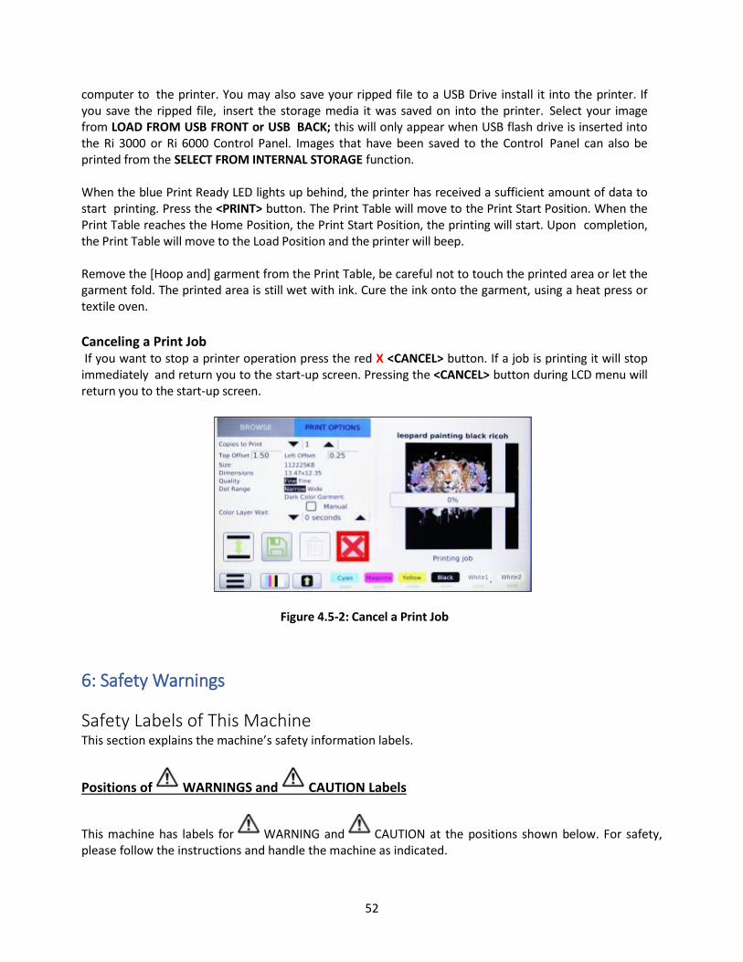
52
computer to the printer. You may also save your ripped file to a USB Drive install it into the printer. If you save the ripped file, insert the storage media it was saved on into the printer. Select your image from LOAD FROM USB FRONT or USB BACK; this will only appear when USB flash drive is inserted into the Ri 3000 or Ri 6000 Control Panel. Images that have been saved to the Control Panel can also be printed from the SELECT FROM INTERNAL STORAGE function. When the blue Print Ready LED lights up behind, the printer has received a sufficient amount of data to start printing. Press the <PRINT> button. The Print Table will move to the Print Start Position. When the Print Table reaches the Home Position, the Print Start Position, the printing will start. Upon completion, the Print Table will move to the Load Position and the printer will beep. Remove the [Hoop and] garment from the Print Table, be careful not to touch the printed area or let the garment fold. The printed area is still wet with ink. Cure the ink onto the garment, using a heat press or textile oven.
Canceling a Print Job If you want to stop a printer operation press the red X <CANCEL> button. If a job is printing it will stop immediately and return you to the start-up screen. Pressing the <CANCEL> button during LCD menu will return you to the start-up screen.
Figure 4.5-2: Cancel a Print Job
6: Safety Warnings
Safety Labels of This Machine This section explains the machine’s safety information labels.
Positions of WARNINGS and CAUTION Labels
This machine has labels for WARNING and CAUTION at the positions shown below. For safety, please follow the instructions and handle the machine as indicated.

53
Front
1. Do not reach far inside the unit. Moving parts inside may cause injury.
2. Do not reach far inside the unit. Moving parts inside may cause injury.
3. Keep your eyes away from the laser aperture so that the laser does not shine directly into your
eyes. The laser can cause injury.
Back
4. This printer uses a class 2 laser radiation. Regarding the position, refer to 3.
5. This label is meant for customer engineers.
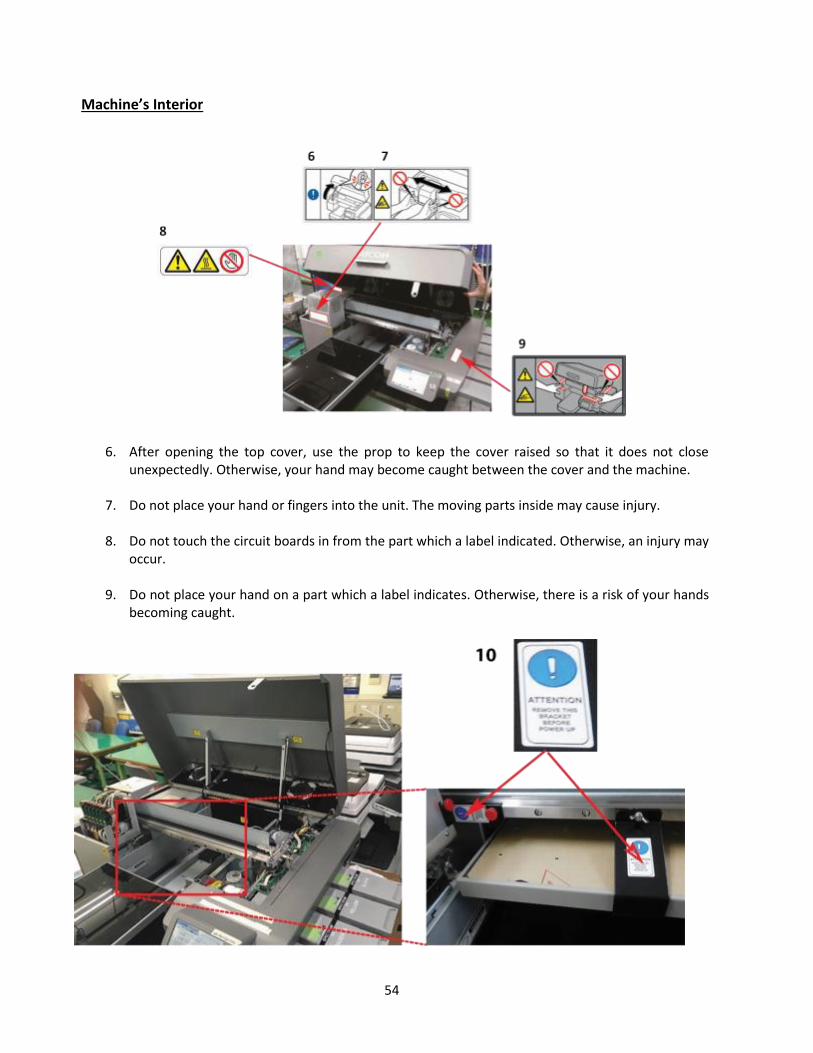
54
Machine’s Interior
6. After opening the top cover, use the prop to keep the cover raised so that it does not close unexpectedly. Otherwise, your hand may become caught between the cover and the machine.
7. Do not place your hand or fingers into the unit. The moving parts inside may cause injury.
8. Do not touch the circuit boards in from the part which a label indicated. Otherwise, an injury may occur.
9. Do not place your hand on a part which a label indicates. Otherwise, there is a risk of your hands
becoming caught.

55
10. Remove the part indicated by the label before the machine is first turned on. Otherwise, there is
the risk of breakage of the machine.
11. Do not touch the circuit board. Doing so could result in injury.
12. Be careful so that your hand is not caught with the main scanning pulley. If it is caught, injury may result.
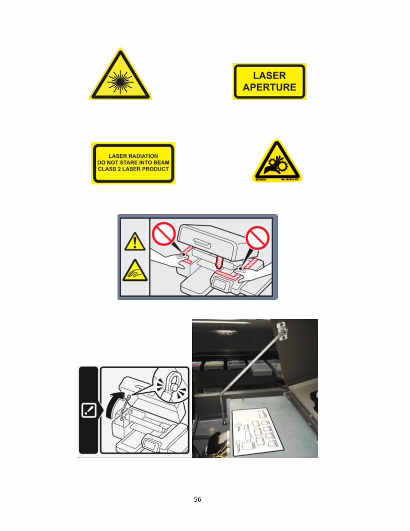
56

57
Figure 4.6-1: Obstruction Sensor and Laser
Figure 4.6-2: Message Received When Obstruction Detected

58
Figure 4.6-3: Message Received When Cover is Open
Cover Open:
• When maintenance is performed, the carriage may move while the top cover is open. Do not touch the carriage while it is moving. Touching it may result in injury. The cover open message appears when a print job, print head clean, ink fill or nozzle check is performed with the cover open. For safety precautions, the cover must be closed to perform these takes in order to avoid injuries. Maintenance can still be performed with the cover open; however the printer must be powered down. Please ensure the lid support rod is properly fastened when performing any maintenance.

59
Chapter 5: Printer Settings
Figure 5.0-1: Printer Setting Menu
1: Select Printer settings Your Printer settings can be accessed in the main menu of your control panel. To access and change these settings Press the <MENU> button and select Settings.
Figure 5.1-1: Printer Settings
2: Language Select the System tab to access the different Languages available for the Ri 3000 and Ri 6000. Scroll through the drop down to find the language desired.

60
Figure 5.1-1: Printer Settings
3: Pre-Print Checks Before beginning a print job, your printer will perform a series of system checks to ensure that it is ready to begin the job. These checks include scanning the table to ensure there are no obstructions, making sure all of your ink cartridges are in a ready state, and checking your power and print-head voltages to ensure that they are all optimal before printing.
Figure 5.3-1: Pre Print Checks Menu Obstruction Detect: When you press the print button, the table will begin to move in towards the home position. As it does so a red laser will scan the table looking for any obstruction that could potentially cause a collision with the print-heads. This is your obstruction sensor. If an obstruction is detected the table will stop at the point of the obstruction and allow you to make the necessary adjustments. Often an obstruction occurs when there is a wrinkle in the garment you are printing on, or when the print table is too high. Warning: Turning the Obstruction Detector off, could result in damage to your print-heads. Cartridge Check: Before printing a job your Ri 3000 or Ri 6000 printer will make sure all six of your cartridges are in a ready state. The printer will make sure all of the carts are inserted and have plenty of ink to complete the print. Additionally, the printer will make sure none of the cartridges have expired and that each color is inserted into the correct slot. The printer will not begin printing unless

61
all the cartridges are confirmed to be ready. It is recommended that this function be left on to prevent damage to printer as a result of expired ink, the ink starvation due to empty carts, and ink contamination due to mismatched cartridges. If you dare to use non-Ricoh authorized inks, you are responsible for any result, including damage, arising out of your use of non- Ricoh authorized inks.
Figure 5.3-1: Pre Print Checks Menu Power Voltages: The printer will automatically read the power voltages any time it is about to print to ensure that all of the components required to print the job are receiving enough power. Color Head Voltages and White Head Voltages: In addition to checking the power voltages the printer will also check to make sure each of your print heads are operating at the optimal voltage. If the heads are not operating at an optimal voltage, the printer will automatically re-calibrate them before printing the job. By default, all of the Pre-Print Checks are set to YES. It is recommended that you do not turn off any of these checks.
4: Wipe After Number of Prints Found under the Printer tab, allows you to control how many prints the printer will do before the wiper blade engages to clean the print-head. By default, this is set to 0, meaning it will not wipe before any print. This is the recommended setting.

62
Figure 5.4-1: Wipe After Number of Prints
5: Cap Head Delay You can also control how long the printer will go before the maintenance station engages to seal off the print- heads. The default for this setting is two minutes.
Figure 5.5-1: Setting Cap Head Delay
The maintenance station seals off the print-heads when the printer is idle; this keeps air from drying out the ink in your print-head nozzles. However, the process of the maintenance station rising to seal off the heads takes a few seconds and it is not necessary to seal off the head in between every print. By default, the Cap Head Delay is set to two minutes. That means that the maintenance station will automatically engage to seal off the print heads two minutes after a shirt is printed. If another shirt is printed within those two minutes the maintenance station will stay down to save time and speed up production. You can use the arrow keys to shorten or lengthen the amount of time the maintenance station will stay down before engaging to seal off the heads. The longest you can set the Cap Head Delay is 15 minutes as we would not recommend the print-head going unsealed for any longer.

63
6: Exhaust Fan You may have noticed two exhaust fans in the back of your printer.
Figure 5.6.-1: Exhaust Fans The purpose of these fans is to collect and filter any ink overspray that comes off of the shirt or Print Heads. The fans will also collect any dust, lint or stray fibers from the garment to keep them from collecting on the interior of your printer. There are a couple of settings you can adjust for the Exhaust fans. By default, the Fan will automatically turn off after 30 seconds. This should be long enough to clear out and filter any residual ink overspray. If you find that ink overspray and dust is still accumulating inside your printer you can use the arrow keys to increase the amount of time the fan stays on. The fan can be set to stay on for up to one minute after the completion of a print. The filters of the exhaust fans will need to be changed every when the filters turn a dark purple. Please see the Maintenance section of this user manual for information on maintaining your exhaust fans.
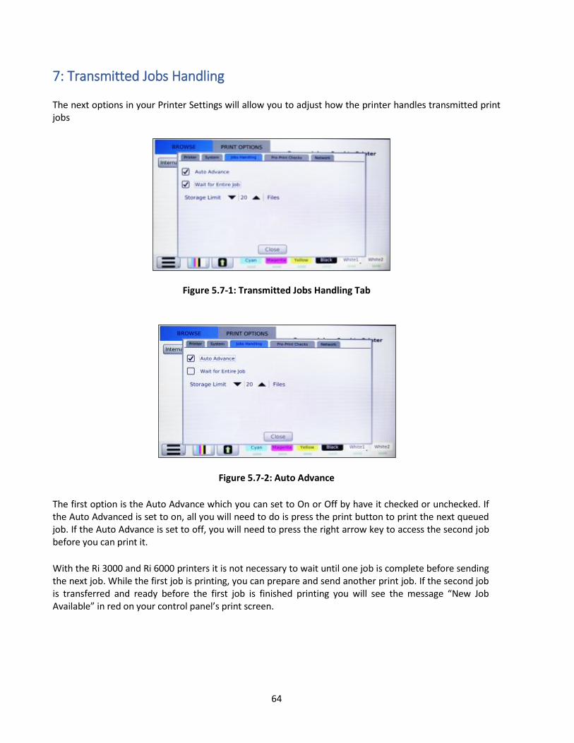
64
7: Transmitted Jobs Handling The next options in your Printer Settings will allow you to adjust how the printer handles transmitted print jobs
Figure 5.7-1: Transmitted Jobs Handling Tab
Figure 5.7-2: Auto Advance
The first option is the Auto Advance which you can set to On or Off by have it checked or unchecked. If the Auto Advanced is set to on, all you will need to do is press the print button to print the next queued job. If the Auto Advance is set to off, you will need to press the right arrow key to access the second job before you can print it.
With the Ri 3000 and Ri 6000 printers it is not necessary to wait until one job is complete before sending the next job. While the first job is printing, you can prepare and send another print job. If the second job is transferred and ready before the first job is finished printing you will see the message “New Job Available” in red on your control panel’s print screen.
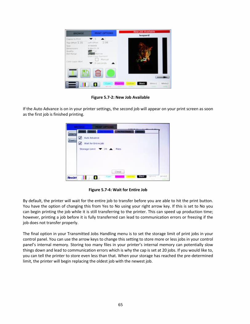
65
Figure 5.7-2: New Job Available
If the Auto Advance is on in your printer settings, the second job will appear on your print screen as soon as the first job is finished printing.
Figure 5.7-4: Wait for Entire Job
By default, the printer will wait for the entire job to transfer before you are able to hit the print button. You have the option of changing this from Yes to No using your right arrow key. If this is set to No you can begin printing the job while it is still transferring to the printer. This can speed up production time; however, printing a job before it is fully transferred can lead to communication errors or freezing if the job does not transfer properly. The final option in your Transmitted Jobs Handling menu is to set the storage limit of print jobs in your control panel. You can use the arrow keys to change this setting to store more or less jobs in your control panel’s internal memory. Storing too many files in your printer’s internal memory can potentially slow things down and lead to communication errors which is why the cap is set at 20 jobs. If you would like to, you can tell the printer to store even less than that. When your storage has reached the pre-determined limit, the printer will begin replacing the oldest job with the newest job.
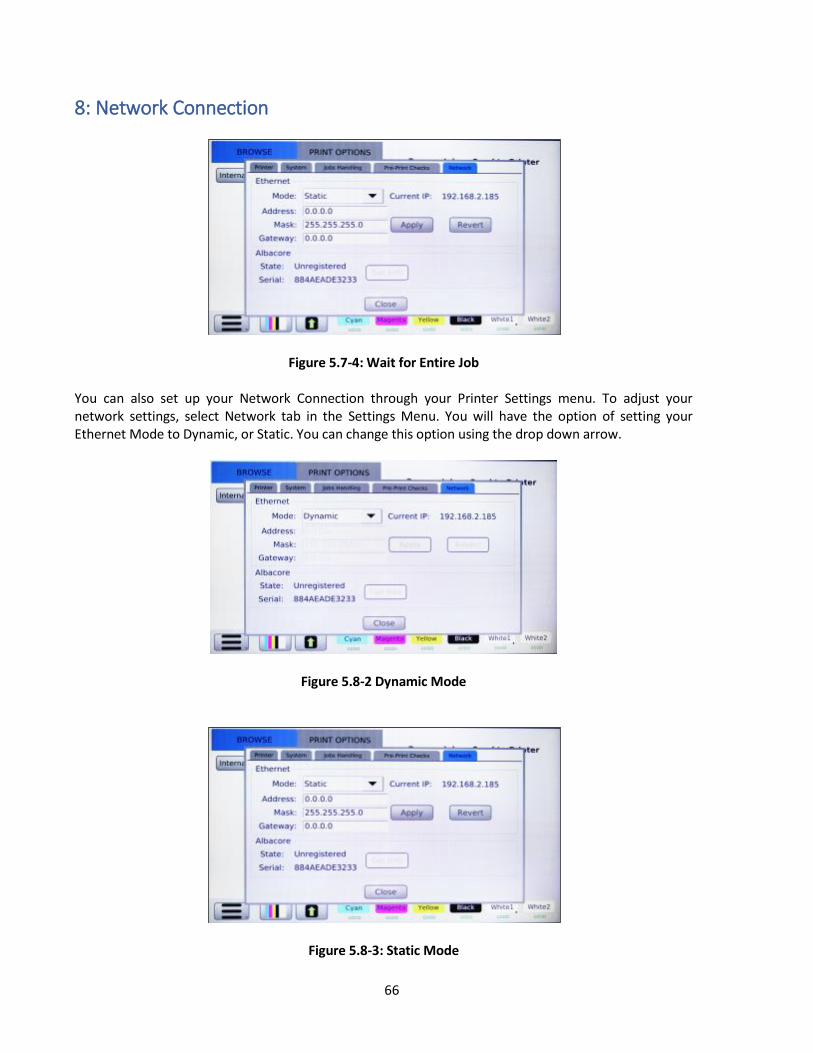
66
8: Network Connection
Figure 5.7-4: Wait for Entire Job
You can also set up your Network Connection through your Printer Settings menu. To adjust your network settings, select Network tab in the Settings Menu. You will have the option of setting your Ethernet Mode to Dynamic, or Static. You can change this option using the drop down arrow.
Figure 5.8-2 Dynamic Mode
Figure 5.8-3: Static Mode
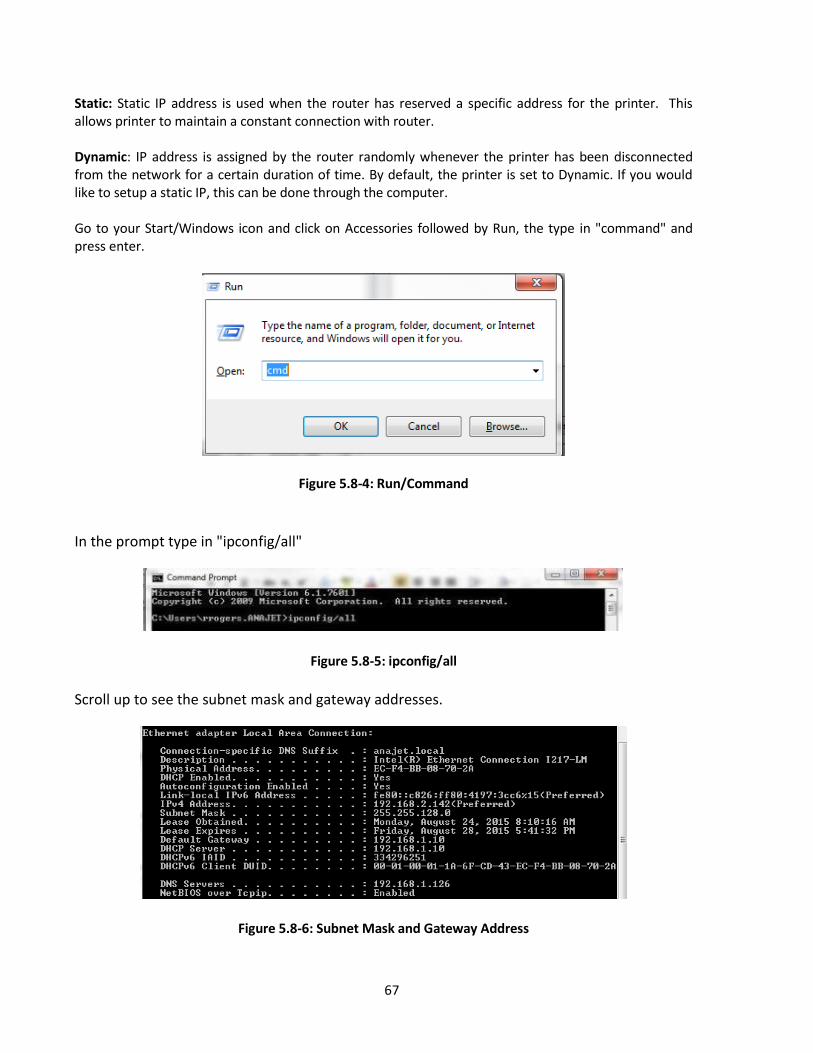
67
Static: Static IP address is used when the router has reserved a specific address for the printer. This allows printer to maintain a constant connection with router. Dynamic: IP address is assigned by the router randomly whenever the printer has been disconnected from the network for a certain duration of time. By default, the printer is set to Dynamic. If you would like to setup a static IP, this can be done through the computer. Go to your Start/Windows icon and click on Accessories followed by Run, the type in "command" and press enter.
Figure 5.8-4: Run/Command
In the prompt type in "ipconfig/all"
Figure 5.8-5: ipconfig/all
Scroll up to see the subnet mask and gateway addresses.
Figure 5.8-6: Subnet Mask and Gateway Address

68
Press enter on modes until static is displayed
Static IP: (192.168.x.x ) IP address of the printer should match the gateway except for the last two sets of digits and not be used by another networked device.
Subnet mask: (255.255.x.x ), determined by the router
Gateway: (192.168.x.x), determine by the router
Figure 5.8-7: Setting Static IP
Once this is complete you can now set the Static IP in your printers control panel.
Select the digit you wish to edit
When finished press <Apply>
9: Printer Number
Figure 5.9-1: Printer Number This setting allows you to assign your printer a specific number. This feature is very helpful when printing with multiple Ri 3000 or Ri 6000 printers through a network connection. If each printer is assigned a specific number, you can then choose which printer to send the print job to by selecting the corresponding number in the Printer Name drop-down menu of the AnaRIP software.
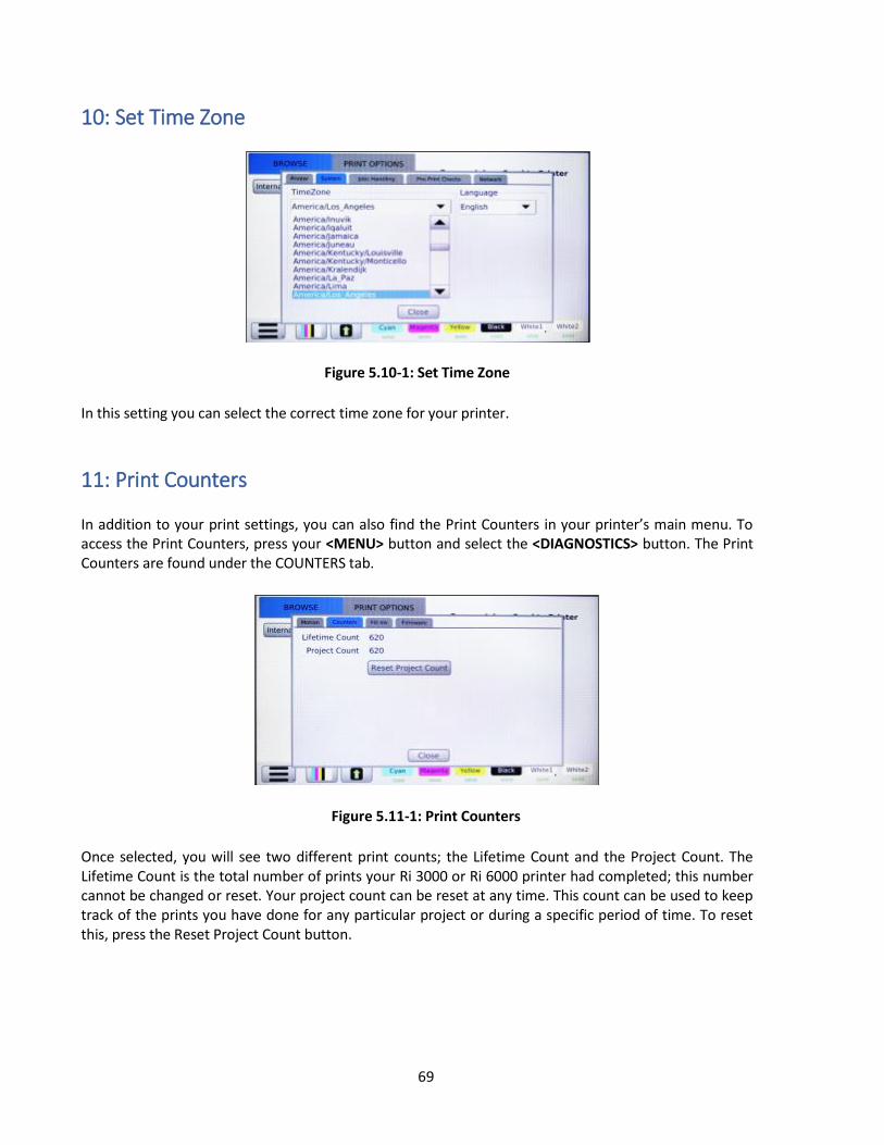
69
10: Set Time Zone
Figure 5.10-1: Set Time Zone
In this setting you can select the correct time zone for your printer.
11: Print Counters In addition to your print settings, you can also find the Print Counters in your printer’s main menu. To access the Print Counters, press your <MENU> button and select the <DIAGNOSTICS> button. The Print Counters are found under the COUNTERS tab.
Figure 5.11-1: Print Counters Once selected, you will see two different print counts; the Lifetime Count and the Project Count. The Lifetime Count is the total number of prints your Ri 3000 or Ri 6000 printer had completed; this number cannot be changed or reset. Your project count can be reset at any time. This count can be used to keep track of the prints you have done for any particular project or during a specific period of time. To reset this, press the Reset Project Count button.

70
Figure 5.12-1: Reset Print Counters
71
Chapter 6: Light Garment Printing Process
1: AnaRIP Raster Image Processor Ri 3000 and Ri 6000 AnaRIP printing software is provided for online download at: http://AnaJet.com/downloads . AnaRIP is a raster image processor (RIP); it is software which converts the graphic design to bitmap data suitable for printing. In the process, smoothing or interpolation algorithms are applied to the graphic data, ink drop size and exact placement of inkjet ink drops are determined. Thus, the quality of the RIP program used greatly affects the quality of print. Generally, RIP programs are difficult to learn and operate in a production environment. AnaJet has created a powerful RIP program with AnaRIP that is optimized for apparel printing.
2: Printer Performance Before you start a print job you will want to make sure you have proper ink flow and print quality to assure the best results. This will require that you perform a Nozzle Check, possibly followed by a Print Head Clean if needed. Before printing make sure that you have gone through all of the setup procedures before this chapter. This first thing you will need to do is a Nozzle Check. (See chapter 2, section 7). The Nozzle Check is going to show you how the Print Head Nozzles are performing and if it will require any Print Head Cleans to restore nozzles that are missing. Each color channel must be showing at least 90% of the total nozzles to be acceptable. Having a good Nozzle Check will give you the best quality prints. Missing nozzles and a poor Nozzle Check will result in low quality prints. If the Nozzle Check is good, then you can now begin printing. If the Nozzle Check is bad you will need to perform a Print Head Clean. (See chapter 2, section 7) This will then be followed by another Nozzle Check to ensure the performance print head nozzles. If the performance is still not acceptable repeat this process.
3: Using the RICOH Ri 3000 and RICOH Ri 6000 AnaRIP Program for Printing Light Garments The definition of a light garment is any print that does not use white ink. The general rule to determine if you need white is if the colors of the image you are printing are darker than the color of the substrate you are printing on, white ink is not required. You will now need to have a graphic that is ready to be place into the AnaRIP software. You should design your images at the full size that they will be printed with a resolution between 100-300 DPI and a canvas size of 14x18 or smaller. The AnaRIP software has a limited number of possible file types you can use. They are JPG, TIFF, and PNG. We recommend that you prepare your images as TIFF or PNG file types. The TIFF and PNG formats both support transparencies generally required for dark shirt printing and use lossless compression that will keep your file high quality. It is also good practice to avoid saving images as JPG. These are compressed file formats originally design

72
for internet use only that loose quality every time they are re-saved. If you are using the native Adobe file formats of AI or PSD you must flatten all of the layers of you image and save this version for printing your complete image. Open the Ri 3000 or Ri 6000 AnaRIP program from your desktop.
Once the program is open you can now place the graphic you would like to use by selecting Place Image under the File drop down in the upper left corner of the program. You may also drag and drop a graphic into the program by clicking on the file and dragging it onto the preview are of the AnaRIP software. You should now see your graphic in the preview screen. (See figure: 6.3-2)
Figure 6.3-1: Place Image Figure 6.3-2: Loading Graphic into RIP
Figure 6.3-3: View Menu At the right top of the settings you will see a drop down select for View. When printing a light garment, you will see 3 choices.
Color Layer: This view will show your original image as it was brought into the software. True View: This view will show what the image will look like when printed. Since the CMYK are somewhat transparent the color of the garment will affect the final look of your printed image. To demonstrate this, click the Textile color drop down and select a different color.

73
Figure 6.3-4: Textile Color Selection
Figure 6.3-5: True View on Different Textile Color As you can see below, the garment color affects the final print color of your image. True View is a very powerful feature of AnaRIP and will assist you in determining whether or not you will need to use white ink.

74
Figure 6.3-6: Color and True View
Color and True View: This view shows both views in the display. The second tab will be the open default view; this tab is called Print Settings. The first option you will encounter in the Print Settings Tab is the Printer Name drop-down. Here you can select where the print job will be sent when the print button is pressed. If USB is selected in the Printer Name drop-down then when the print button is pressed the job will RIP to the Ri 3000 or Ri 6000 printer that is currently connected to the computer through the USB cable. Printing this way is similar to using any standard desktop printer. If Ri 3000 or Ri 6000 File is selected, then the AnaRIP software will process the file to destination of your choice. You can RIP your files to your computer’s desktop or to a folder of your choice and print them later, or you can RIP your files to a USB Flash Drive, which can then be plugged into the printers control panel.
Figure 6.3-7: Select Printer If you have multiple printers, you can connect them all on a network and assign each one a number through the printers control panel. Then when printing, you can select which printer to send the job to by selecting it in your Printer Name drop-down. The preview will match the table platen size you have selected. The default Platen setting is Main (14 x 18 in), if you are using a different table the table size can be changed in the program under Platen Size and the preview print area will change to this tables dimensions.

75
Figure 6.3-8: Platen Size
Most printing will be done using the Main platen which measures 14” x 18”. For printing youth size shirts and sleeves, you can install the Youth Print Table which is 8.5” x 12” in size, or the Sleeve Print Table which is 4” x 16.8” in size. (See Figure 6.3-9). When using these tables, choose the corresponding platen size. Doing so will change the application’s preview window to correspond to the narrower print area as well as automatically adjust the print origin.
Figure 6.3-9: Sleeve and Youth Size Print Table and Print Origin
The Ri Small Print Adapter can be used to simplify the process of printing pocket drop graphics. The 5.5” x 4.0” Pocket Adapter can be placed either portrait or landscape and on top of either side of the front of the Print Table. The exact offset measurements of the Pocket Adapter are shown in Figure 6.3-10.
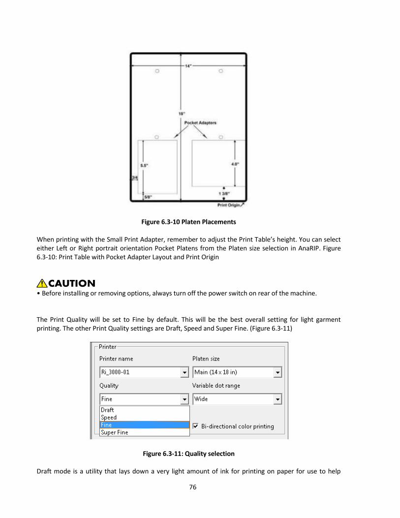
76
Figure 6.3-10 Platen Placements When printing with the Small Print Adapter, remember to adjust the Print Table’s height. You can select either Left or Right portrait orientation Pocket Platens from the Platen size selection in AnaRIP. Figure 6.3-10: Print Table with Pocket Adapter Layout and Print Origin
• Before installing or removing options, always turn off the power switch on rear of the machine. The Print Quality will be set to Fine by default. This will be the best overall setting for light garment printing. The other Print Quality settings are Draft, Speed and Super Fine. (Figure 6.3-11)
Figure 6.3-11: Quality selection Draft mode is a utility that lays down a very light amount of ink for printing on paper for use to help

77
position items to print. The Speed, Fine and Super Fine modes print the image using the same volume of ink but they print using smaller steps according to the higher quality which can produce better image quality. Please note that the print speed will be affected by the higher settings. You will now need to select a Variable Dot Range, the default setting is Narrow. The Variable Dot range will control the amount of ink saturation on a print. The Variable Dot range can also be adjusted when printing on different types of garments. A Narrow Variable Dot Range for a thin material and a Wide Variable Dot Range for a sweatshirt for example. (See figure 6.3-12)
Figure 6.3-12: Variable Dot Range Number of Copies is where you enter the amount of prints you would like to send to the printer. This can also be changed from the Control Panel if needed before printing.
Figure 6.3-13: Number of Copies / Bi-directional Color Printing
Make sure that the Bi-directional color printing checkbox is checked. In most cases, you will want to use Bi- Directional Printing, the Print Head will print when moving both directions and make print speed much faster.
Color is laid down in order: Cyan> Magenta> Yellow> Black> Black> Yellow> Magenta> Cyan. If your image is very small fast printing may cause puddling or running ink, if this is the case you can uncheck this box to slow the amount of ink delivered.

78
Also, choosing to leave Bi-Directional unchecked changes the ink drops to lay down differently, Color would be laid down Cyan>Magenta>Yellow>Black>Cyan>Magenta>Yellow>Black. This produces a more color accurate image at cost of speed.
Figure 6.3-14: Sizing and Positioning Scaling will adjust your image Horizontal and Vertical size by a percentage. If the lock is clicked on, the aspect ratio of the image will stay the same so the image will not become distorted in size. Size will affect the images size in specific measurements horizontally and vertically. If the lock is clicked on the aspect ratio or the image will stay the same so the image will not become distorted in size. You can also change the image print size by clicking on and dragging on the image frame in the preview area. I you drag the corners the aspect ratio will be maintained. If you drag the tops or sides you will stretch or compress your image.
Position is for placement of your graphic into a specific area of the Print Table. This will be used to move a graphic higher or lower vertically or left to right horizontally. The image can also be moved by dragging the image with your mouse in the preview screen. If you want to center your image on the print table horizontally or vertically, the Center button for each can be used. Using the Rotate buttons will rotate your image in 90 degree increments left or right.
Input Color Profile An ICC profile contains information for converting an image between a device-specific color space (Ri 3000 or Ri 6000) and a device-independent color space (Photoshop). The input ICC profile translates color data created on a device (such as a digital camera) into the PCS, profile connection space. The RIP uses the output ICC Ink Set Profile (PowerBright or PowerBright Plus) to convert from the PCS into the native color space of the Ri 3000 and Ri 6000.

79
Figure 6.3-15: Color Controls Input Color Profile
Figure 6.3-16: ICC Input Profile Images created in Photoshop most often contain a built a profile for the specific color space the image was designed in. The rip allows you to change use a different ICC profile instead of the ICC profile that is part of the image file.

80
Figure 6.3-17: Rendering Intent
Rendering intent specifies the rendering intent that this step should associate with the job. Rendering intents inform the printer what action to take when a print job includes colors that lie outside the color range of the printer.
Perceptual (default): The printer adjusts all the colors in the image so they are all in the color range of the printer and maintain their color relationships to each other. Saturation: The printer substitutes the nearest color that it can print for out-of-range colors and adjusts in-range colors to make them more vivid. Relative Colorimetric: The printer substitutes the nearest color that it can print for out-of-range colors; in-range colors are not adjusted. Absolute Colorimetric: The printer substitutes the nearest color that it can print for out-of-range colors, and then all colors are adjusted based on the white point of the media.
Figure 6.3-18 Color Controls
The Color Adjustments Tab will allow you to make adjustments to the graphics Brightness, Contrast and Saturation. The Color Controls effect will be visible in the preview screen when they are adjusted. (See figure 6.3-19 to 6.3-24)

81
Figure 6.3-19 & 6.3-20 Brightness Adjustment
Brightness Up
Brightness Down Figure 6.3-19 Figure 6.3-20
Figure 6.3-21 & 6.3-22 Contrast Adjustment
Contrast Up
Contrast Down
Figure 6.3-21 Figure 6.3-22
Figure 6.3-23 & 6.3-24 Saturation Adjustment
Saturation Up
Saturation Down Figure 6.3-23 Figure 6.3-24
Figure 6.3-19 to 6.3-24: Color Adjustments Previews
Because we are printing light garments, the Underbase Tab will not be used at this time. Once you have made all of your adjustments to the printing Size, Position, Quality, Variable Dot Range and Color Adjustments you are ready to save your design or print your image. To save the design for later changes select File - Save Design. Saving the design will save your settings as well as a link to your image file. (Be sure not to move or delete that Image File or when you open the
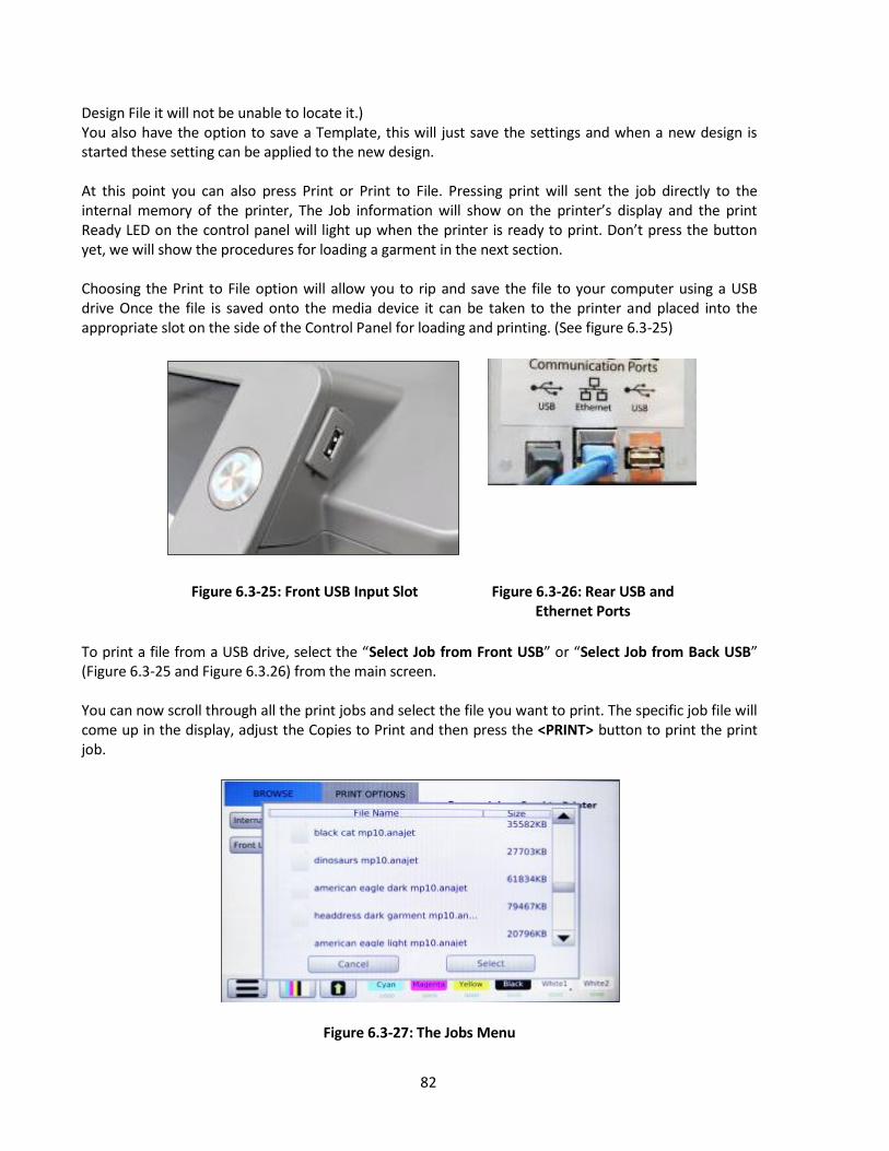
82
Design File it will not be unable to locate it.) You also have the option to save a Template, this will just save the settings and when a new design is started these setting can be applied to the new design. At this point you can also press Print or Print to File. Pressing print will sent the job directly to the internal memory of the printer, The Job information will show on the printer’s display and the print Ready LED on the control panel will light up when the printer is ready to print. Don’t press the button yet, we will show the procedures for loading a garment in the next section. Choosing the Print to File option will allow you to rip and save the file to your computer using a USB drive Once the file is saved onto the media device it can be taken to the printer and placed into the appropriate slot on the side of the Control Panel for loading and printing. (See figure 6.3-25)
Figure 6.3-25: Front USB Input Slot
Figure 6.3-26: Rear USB and
Ethernet Ports
To print a file from a USB drive, select the “Select Job from Front USB” or “Select Job from Back USB” (Figure 6.3-25 and Figure 6.3.26) from the main screen. You can now scroll through all the print jobs and select the file you want to print. The specific job file will come up in the display, adjust the Copies to Print and then press the <PRINT> button to print the print job.
Figure 6.3-27: The Jobs Menu
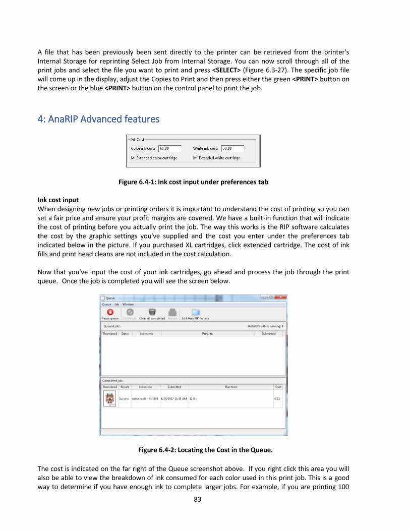
83
A file that has been previously been sent directly to the printer can be retrieved from the printer's Internal Storage for reprinting Select Job from Internal Storage. You can now scroll through all of the print jobs and select the file you want to print and press <SELECT> (Figure 6.3-27). The specific job file will come up in the display, adjust the Copies to Print and then press either the green <PRINT> button on the screen or the blue <PRINT> button on the control panel to print the job.
4: AnaRIP Advanced features
Figure 6.4-1: Ink cost input under preferences tab Ink cost input When designing new jobs or printing orders it is important to understand the cost of printing so you can set a fair price and ensure your profit margins are covered. We have a built-in function that will indicate the cost of printing before you actually print the job. The way this works is the RIP software calculates the cost by the graphic settings you've supplied and the cost you enter under the preferences tab indicated below in the picture. If you purchased XL cartridges, click extended cartridge. The cost of ink fills and print head cleans are not included in the cost calculation. Now that you've input the cost of your ink cartridges, go ahead and process the job through the print queue. Once the job is completed you will see the screen below.
Figure 6.4-2: Locating the Cost in the Queue.
The cost is indicated on the far right of the Queue screenshot above. If you right click this area you will also be able to view the breakdown of ink consumed for each color used in this print job. This is a good way to determine if you have enough ink to complete larger jobs. For example, if you are printing 100

84
black shirts, this would indicate the amount of white ink for each shirt. You can now buy your supplies in advance to ensure no shortage. Please see example below:
Figure 6.4-3: Cost Breakup per Color
Understanding ICC profiles, how to use our preset profiles and how to update your own profiles within our AnaRIP software. If you do not completely understand how to make or manipulate ICC profiles, we suggest you use your preset profiles. If you open the AnaRIP software under the preferences tab seen below, this is where you enable or disable our preset profiles. Manage Ink Set Profiles By default, the RIP has two default ink sets, PowerBright and PowerBright Plus Ink Sets. PowerBright is optimized for Ricoh authorized ink. If you end up developing your own color profile and/or color curves to get your desired results, you will need to add an additional Ink Set Profile.
Figure 6.4-4: Ink Set Profile Management.
To add an additional Ink Set, select the Plus sign and proceed to fill in the ink set editor.

85
Figure 6.4-5: Ink Set Editor
Manage Color Profiles To add a new ICC color profile, click on the plus icon and locate the location of the file on the PC. Profiles can be created through the use of X-Rite IProfiler or other similar products.
Figure 6.4-6 ICC Color Profiles. Manage Color Linearization Curves
To add a new linearization curve, click on the plus icon and locate the location of the file on the PC. AnaRIP comes with a curve editor preinstalled. The curve editor can be located in the Start Menu of the PC
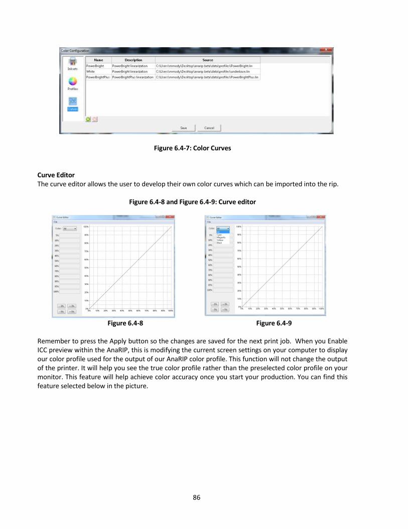
86
Figure 6.4-7: Color Curves Curve Editor The curve editor allows the user to develop their own color curves which can be imported into the rip.
Figure 6.4-8 and Figure 6.4-9: Curve editor
Figure 6.4-8 Figure 6.4-9
Remember to press the Apply button so the changes are saved for the next print job. When you Enable ICC preview within the AnaRIP, this is modifying the current screen settings on your computer to display our color profile used for the output of our AnaRIP color profile. This function will not change the output of the printer. It will help you see the true color profile rather than the preselected color profile on your monitor. This feature will help achieve color accuracy once you start your production. You can find this feature selected below in the picture.
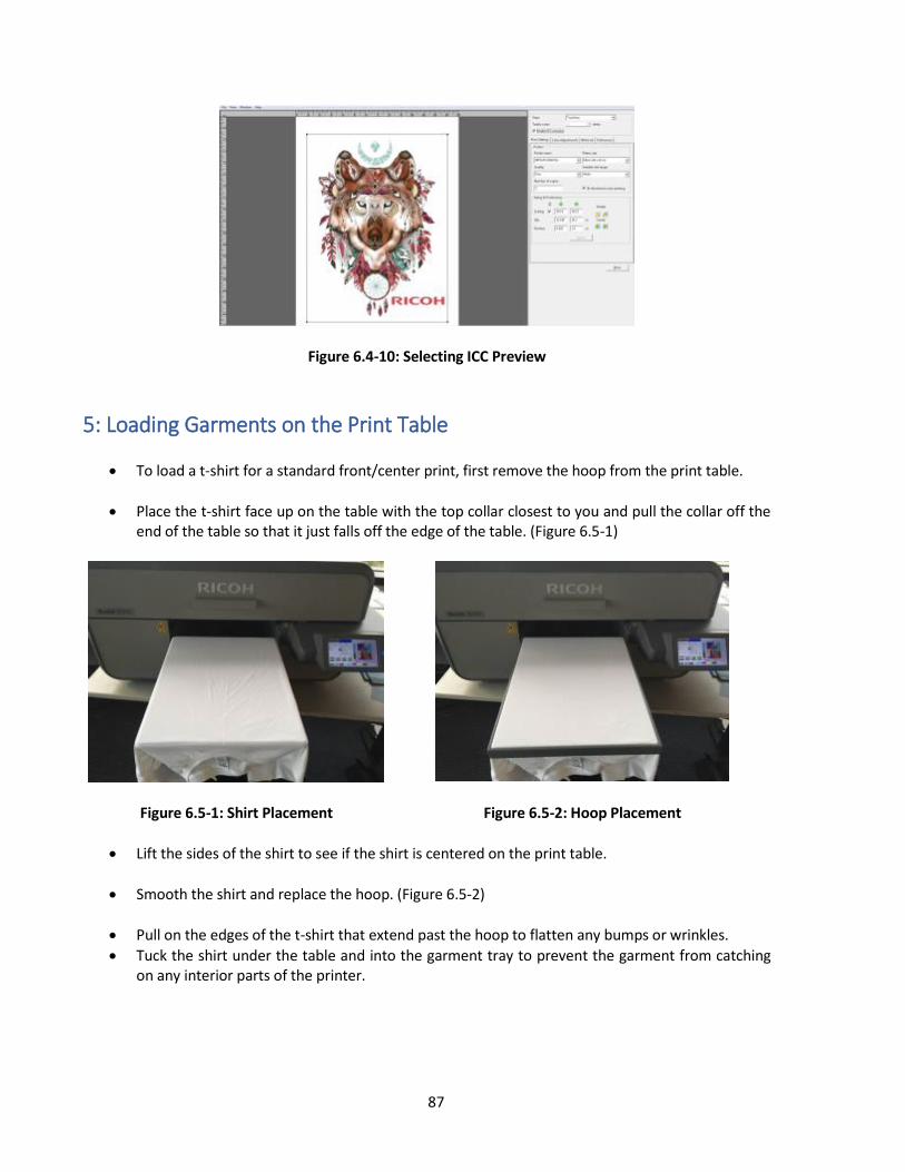
87
Figure 6.4-10: Selecting ICC Preview
5: Loading Garments on the Print Table
To load a t-shirt for a standard front/center print, first remove the hoop from the print table.
Place the t-shirt face up on the table with the top collar closest to you and pull the collar off the end of the table so that it just falls off the edge of the table. (Figure 6.5-1)
Figure 6.5-1: Shirt Placement
Figure 6.5-2: Hoop Placement
Lift the sides of the shirt to see if the shirt is centered on the print table.
Smooth the shirt and replace the hoop. (Figure 6.5-2)
Pull on the edges of the t-shirt that extend past the hoop to flatten any bumps or wrinkles.
Tuck the shirt under the table and into the garment tray to prevent the garment from catching on any interior parts of the printer.

88
6: Removing Garments from the Print Table After printing has completed, remove the hoop from the table. Do not touch the image as the ink is still wet at this point. Remove the garment from the table being sure that the printed image is facing you when it is removed. Do not let the shirt fold or touch itself as this could cause ink transfer to other parts of the garment. Take the garment to your heat press or conveyer dryer fix the ink to the garment.
• When removing the fabric, be careful so that your hand or any other part of your body does not come in contact with ink. If your skin comes in contact with ink, wash the affected area thoroughly with soap and water. If your clothing comes into contact with ink, wash the stained area with cold water.
7: Set the Image with Heat User’s Notes • For information about how to use the heat press device, see the manual. In order to cure the ink so that your images will be color-fast when washing, it is necessary to heat treat the image so that the image bonds with the garment.
If you are using a heat press place the garment on the heat press platen with the printed side up.
Pull by the edges to ensure proper placement and that it is flat on the heat press, minding not to touch the wet ink. Cover the garment with a sheet of SoftTouch heat press paper, for Ricoh authorized ink. Close the press and heat the printed garment for 40 seconds at 356ºF or 180ºC. The pressure applied by the heat press when close should be in the light to medium range. When the time is completed open the heat press and remove the heat press paper immediately. SoftTouch heat press paper can be reused several times.
Instead of SoftTouch, a Teflon sheet or Kraft Paper Cover Sheet can be used. When reusing the SoftTouch Paper, make sure there are no wrinkles as these will transfer to the garment. If this is the case use a new sheet. The printed garment is now completed. If you are also printing dark shirt images you need to reduce the heat press temperature and increase the time. Settings for dark garments of 330ºF or 165ºC for 90 seconds will also work for light garments.
If you are using a textile oven or conveyor dryer, please test the temperature of the printed image when it exits the dryer to assure that it has reached 330˚F or 165˚C. Also, please do a wash test of your first attempts to be sure that the inks have cured properly and wash ability has been attained.

89
Ricoh Authorized Ink Temperature Time
Light Shirt with Heat Press 356˚F or 180˚C 40 seconds
Light Shirt with Conveyer Dryer Printed image must reach 330˚F or 165˚C
Varies
Figure 6.7-1: Heat Curing Temperature and Time Variations for Light Garments

90
Chapter 7: Printing on Dark Garments
1: Basic Dark Garment Printing Process Before you start any print job you will want to make sure you have proper ink flow and print quality to assure the best results. This will require that you perform a Nozzle Check, possibly followed by a Print Head Clean if needed. Performing a Nozzle Check is further detailed in Chapter 2 Section 7. Before printing make sure that you have gone through all of the setup procedures before this chapter. The definition of a dark garment is any print that uses white ink. The general rule to determine if you need white is if the colors of the image you are printing are lighter than the color of the substrate you are printing on, white ink is required. (Figures 7.1-1, 7.1-2, 7.1-3)
Figure 7.1-1: Image Darker Than Garment- White Ink Not Needed
Figure 7.1-2 and 7.1-3: Image Lighter Than Garment- White Ink Needed
Figure 7. 1-2 Figure 7. 1-3
The dark colored garment printing principles are essentially the same as light garment printing with

91
added procedures. Refer to the basic white garment printing process prior to learning the black garment printing process. This chapter addresses only those features unique to black garment printing. The basic process is as follows:
Pre-treat the garment with Ricoh authorized Pre-treatment Liquid. You only need to pretreat the area you will print on.
Allow the pre-treatment to dry.
Before printing press garment for 5 seconds to flatten and stray fibers and remove wrinkles.
Place the dark garment on the Print Table.
Send the print job from the PC, using the Ri 3000 or Ri 6000 AnaRIP program or load the print job from a USB drive.
Press the <PRINT> button when the blue Print Ready LED lights up to print the white ink Undercoating.
When white ink undercoating is completed the printer will then automatically print the color layer.
Upon completion of the print, fix the ink onto the garment with a heat press or conveyer dryer. Dark garment printing with white ink is a more involved process than light garment printing. This is particularly true with the print image preparation and print settings. It is very desirable for the operator to practice printing dark garments before he starts using the system for commercial printing of dark garments.
2: Maintenance of White Ink Although Ricoh authorized white ink performs better than any other competitive products for printing dark shirts and the Ri 3000 and Ri 6000 printers require less maintenance compared to other printers, today’s direct to garment white inks still require a fair amount of maintenance. (See the Technical Notes in Section 3 below.) The garments should never touch the Print Head or Nozzle Plate as it can scratch the Nozzle Plate Coating or cause clogging of the nozzles. This is particularly true when printing with black garments sprayed with Pre- treatment Liquid. Before printing, check the Print Table Height to ensure that the garments will not touch the Print Head Nozzle Plates. Printer maintenance takes on added importance when the printer is used for dark garment printing. The white ink contains a higher percentage of solids than colored inks, resulting in more ink residues accumulating on and around the Print Head, Wiper Blade and Maintenance Station. When white ink is used, the white residues accumulating around the Maintenance Station and Nozzle Plate may cause the Maintenance Station not to seal properly during cleaning cycles. This accumulation of foreign materials will tend to clog the Print Head and shorten its life unless they are maintained regularly.

92
3: Scheduled Maintenance It is very important to follow the printer maintenance schedule. If neglected, it may become necessary to ship the unit back to a RICOH Ri 3000/Ri 6000 repair facility and put the printer through an extensive and expensive refurbishment process. These maintenance procedures are presented in a detailed manner in Chapter 9: Maintenance and Transportation.
4: Pre-treatment of Dark Colored Garments
• When swallowing or inhaling ink, cleaning solution, HV storage solution or pretreatment liquid, or when getting them in the eye, follow the guidance in the appropriate safety data sheet (SDS). Download the SDS from the AnaJet website at http://anajet.com/technical-documentation
• Place ink, cleaning solution, HV storage solution, and pretreatment liquid in a cool, well-ventilated place out of the reach of children. • Keep waste ink, containers for ink, cleaning solution, HV storage solution, and pretreatment liquid, and components that have been in contact with ink out of the reach of children. • When handling ink, cleaning solution, HV storage solution, or pretreatment liquid, avoid getting anything on your clothing. If you do, wash the stained area with cold water. Pre-treatment Liquid is to be used with care. Do not let it contact your eyes. Do not breathe in the vapor or mist. Thoroughly wash your hands after handling it. If your clothing gets contaminated, wash it before reuse. If an accident happens please follow the Caution and First Aid instructions on the Pre-treatment Liquid bottle label. Due to the corrosive nature of the pre-treatment solution, we recommend that all users apply pre-treatment using gloves and a dust mask. Follow the instructions on the label. For dark garment printing, the most critical process is proper application of Pre-treatment Solution onto the garments. Spotty or improper application of the Pre-treatment or improper drying will result in white ink not bonding properly with the garment fabric. This in turn will cause poor image quality and premature wash out of the image. For additional information, please refer to the SDS sheets located on the website at http://anajet.com/technical-documentation

93
You will need the following for Pre-treatment Application: A well-ventilated room. Good ventilation is essential for worker comfort and health. Application
of Pre- treatment Liquid outdoors is not recommended on windy days as it can cause uneven application. It is recommended that a room away from the printer be dedicated to the application of pre-treatment so that the spray will not affect your printer.
Our recommended process for applying the Pre-treatment Liquid is to use a High Volume Low Pressure (HVLP) spray gun. These spray guns are commonly used for applying paints and are available from paint supply stores or home improvement stores. The Wagner Control Spray Gun, available for US customers ONLY (Figure 7.4-1) and Campbell Hausfeld Paint Sprayer, found in local hardware stores are both good choices.
Image 7.4-1: Wagner Control Spray Gun
Pre- treatment Application Procedure: Dilute the RIOCH authorized Pretreatment Liquid with a 70:30 ratio amount of distilled water,
70% pretreatment: 30% part water. Fill the sprayer reservoir with the mixture. It is very important to use distilled water as city water, well water or filtered water may have mineral content that can affect the performance of the pre-treatment.
Lay down the garment on a flat spray table. Make the garment even and flat.
Apply the pre-treatment mix with the sprayer. Apply an adequate and even amount to where the material has an even wet sheen. Remember you only need to apply the pre-treatment to the areas that will be printed on.
Going in only one direction use a plastic squeegee to help spread the pre-treatment evenly after spraying. This also flattens any fabric fibers that may have risen due to the application of the wet pre-treatment.
Dry the garment, you can achieve an excellent result by letting the garments air dry or you can use a heat press in the hover position (This means the heat press is not closed but has a 1 to 1/2 inch gap to allow the steam to escape), blow dryer or a heat tunnel. Do not dry your garments in a tumble dryer. These dryers are full of lint and since the pre-treatment is wet and somewhat sticky you will end up with lint stuck to the pre-treatment.
Once the garment is dry to the touch you can print on it. If you plan on storing the garments for later use, be sure that they are completely dry beforehand to prevent mildew.

94
When first attempting the pre-treatment process test with a few shirts to determine how much to spray. Too much pre-treatment can leave dark areas on the garments. Too little pre-treatment can make the prints look dull. The performance of white ink is highly dependent on proper application of pre-treatment.
If you do not wish to dilute your own pretreatment, Pre-Mixed Pretreatment is also available.
Figure 7.4-2: Poor Pre-Treatment Can Be Seen on the Left Side of this Image
5: Dark Garment Ri 3000 or Ri 6000 AnaRIP Settings Import and set up your image as described in the previous chapter (see Chapter 6: Light Garment Printing Process) When printing onto a dark garment or any garment that needs white ink to be printed the Enable white ink checkbox needs to be checked in the Ri 3000 and Ri 6000 RIP program.
Figure 7.5-1: Underbase When you enable white ink three things will happen. First the background will switch to black, unless you have a different Preview Color selected. Select the Underbase layer in the view section where True View is displayed by default. (Figure 7.5-2)
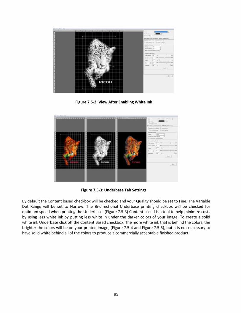
95
Figure 7.5-2: View After Enabling White Ink
Figure 7.5-3: Underbase Tab Settings
By default the Content based checkbox will be checked and your Quality should be set to Fine. The Variable Dot Range will be set to Narrow. The Bi-directional Underbase printing checkbox will be checked for optimum speed when printing the Underbase. (Figure 7.5-3) Content based is a tool to help minimize costs by using less white ink by putting less white in under the darker colors of your image. To create a solid white ink Underbase click off the Content Based checkbox. The more white ink that is behind the colors, the brighter the colors will be on your printed image, (Figure 7.5-4 and Figure 7.5-5), but it is not necessary to have solid white behind all of the colors to produce a commercially acceptable finished product.
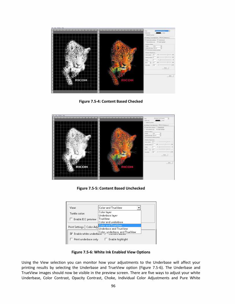
96
Figure 7.5-4: Content Based Checked
Figure 7.5-5: Content Based Unchecked
Figure 7.5-6: White Ink Enabled View Options
Using the View selection you can monitor how your adjustments to the Underbase will affect your printing results by selecting the Underbase and TrueView option (Figure 7.5-6). The Underbase and TrueView images should now be visible in the preview screen. There are five ways to adjust your white Underbase, Color Contrast, Opacity Contrast, Choke, Individual Color Adjustments and Pure White
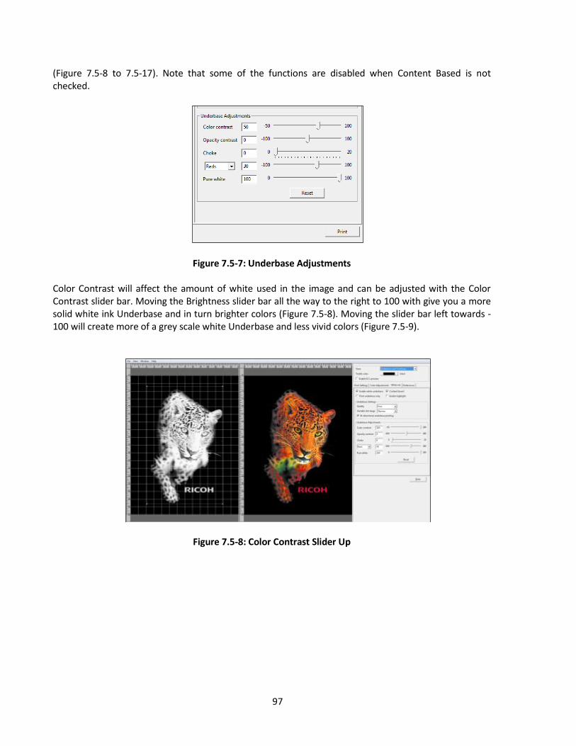
97
(Figure 7.5-8 to 7.5-17). Note that some of the functions are disabled when Content Based is not checked.
Figure 7.5-7: Underbase Adjustments Color Contrast will affect the amount of white used in the image and can be adjusted with the Color Contrast slider bar. Moving the Brightness slider bar all the way to the right to 100 with give you a more solid white ink Underbase and in turn brighter colors (Figure 7.5-8). Moving the slider bar left towards - 100 will create more of a grey scale white Underbase and less vivid colors (Figure 7.5-9).
Figure 7.5-8: Color Contrast Slider Up

98
Figure 7.5-9: Color Contrast Slider Down Opacity Contrast is only active when your image has a soft or semi-transparent edge or the image has semi-transparent colors in it. Moving the slider bar to the left will reduce the amount of white Underbase beneath these areas to help create a smoother blend. (Figure 7.5-10 and Figure 7.5-11)
Figure 7.5-10: Opacity Contrast Up
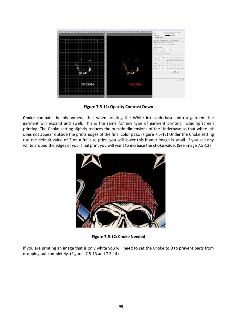
99
Figure 7.5-11: Opacity Contrast Down Choke combats the phenomena that when printing the White ink Underbase onto a garment the garment will expand and swell. This is the same for any type of garment printing including screen printing. The Choke setting slightly reduces the outside dimensions of the Underbase so that white ink does not appear outside the prints edges of the final color pass. (Figure 7.5-12) Under the Choke setting use the default value of 2 on a full size print, you will lower this if your image is small. If you see any white around the edges of your final print you will want to increase the choke value. (See image 7.5-12)
Figure 7.5-12: Choke Needed
If you are printing an image that is only white you will need to set the Choke to 0 to prevent parts from dropping out completely. (Figures 7.5-13 and 7.5-14)
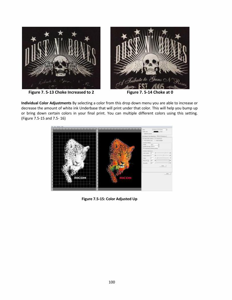
100
Figure 7. 5-13 Choke Increased to 2 Figure 7. 5-14 Choke at 0
Individual Color Adjustments By selecting a color from this drop down menu you are able to increase or decrease the amount of white ink Underbase that will print under that color. This will help you bump up or bring down certain colors in your final print. You can multiple different colors using this setting. (Figure 7.5-15 and 7.5- 16)
Figure 7.5-15: Color Adjusted Up
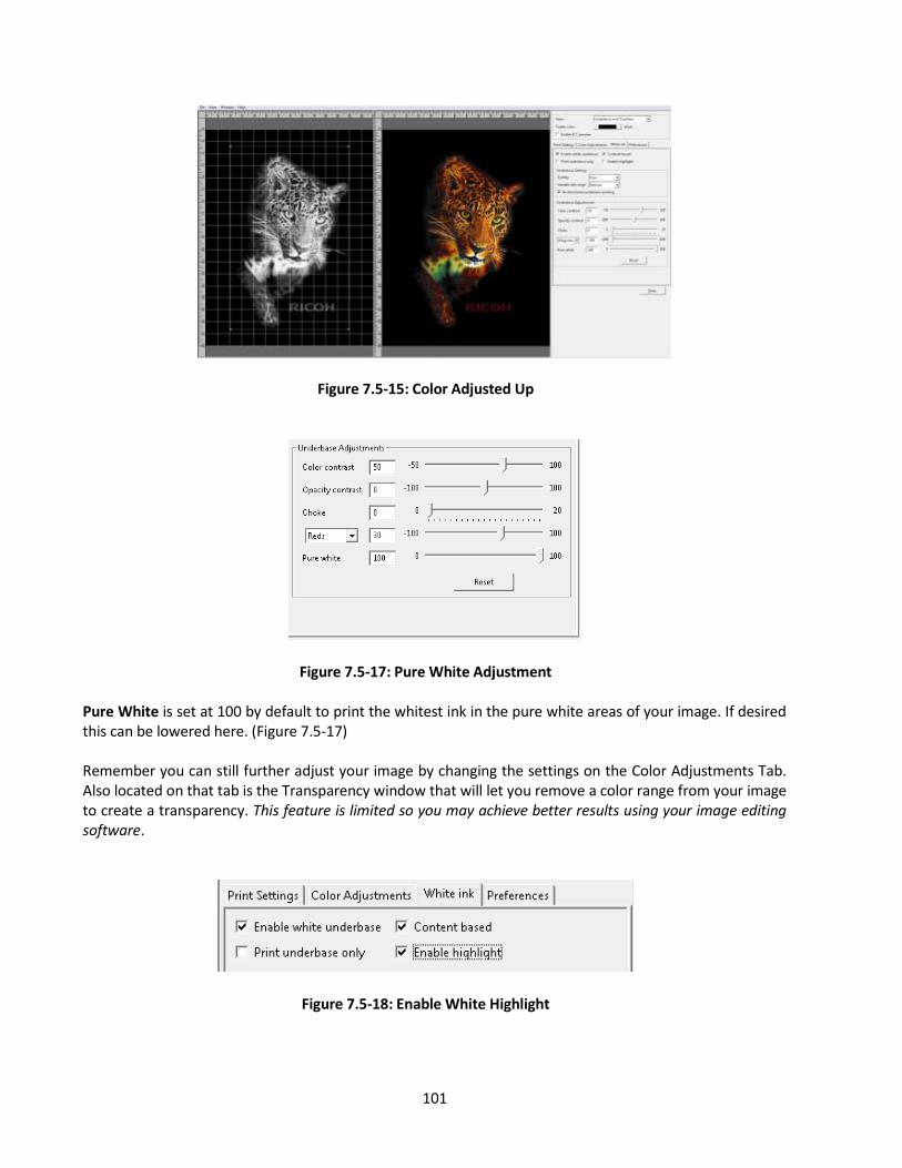
101
Figure 7.5-15: Color Adjusted Up
Figure 7.5-17: Pure White Adjustment Pure White is set at 100 by default to print the whitest ink in the pure white areas of your image. If desired this can be lowered here. (Figure 7.5-17) Remember you can still further adjust your image by changing the settings on the Color Adjustments Tab. Also located on that tab is the Transparency window that will let you remove a color range from your image to create a transparency. This feature is limited so you may achieve better results using your image editing software.
Figure 7.5-18: Enable White Highlight

102
Figure 7.5-19 White Highlight Enabled Figure 7.5-20 Highlight Layer View
White Highlight allows for a second layer of pure white to be printer during the color layer,
allowing for a brighter white. If using white highlight, make sure there is dead pixel space between any large amounts of pure white and any CMYK color as it may cause white ink to mix the color at the edge.
To remove all of a specific color range, select Select Color. (Figure 7.5-21) Then click the color you want to remove from your image. The selected color will be removed from the entire image. You can increase the range of the color removed by adjusting the Color Tolerance slider. (Figure 7.5-22)
Figure 7.5-21: Select Color to be Removed

103
Figure 7.5-21: Select Border Color to be Removed
You can also select to remove a Border color. This removes a contiguous color up to when it changes to another color. Please note that better results will be achieved by using your image editing software to create transparencies. Once you have completed your settings and adjustments you can now send your image to the printer by pressing Print or save the graphic to your computer or an USB drive by selecting Print to file. The Printer will first print the White layer. Once completed, the printer will print the Color Pass. Since the white Underbase layer may not be dry enough to receive the color layer, there is an adjustment on the printer’s job window to set a wait time before the color layer is printed. By default, it is set to 0. (Figure 7.5-23) By checking the Manual box you can set it to Manual color layer print. (Figure 7.5-24) This means that you will need to press the <PRINT> button to have the color layer print. By doing this on your first print of a particular job you will be able to determine the wait time if any that will be needed to produce an acceptable print. You can then adjust the color layer wait time by pressing the Up or Down buttons to the needed setting in increments of 10 seconds..
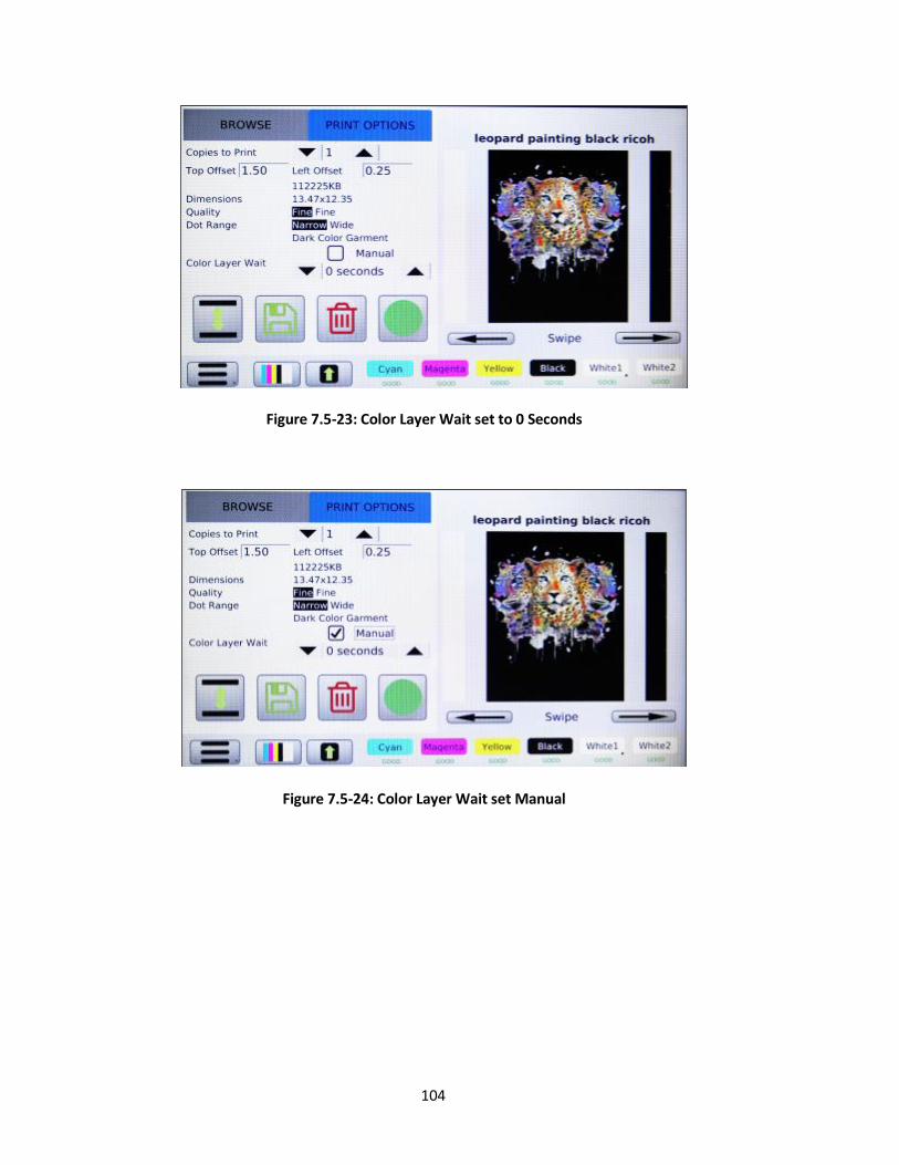
104
Figure 7.5-23: Color Layer Wait set to 0 Seconds
Figure 7.5-24: Color Layer Wait set Manual

105
Figure 7.5-25: Color Layer Wait Time
6: Set the Image with Heat Treatment
User’s Notes • For information about how to use the heat press device, see the manual. In order to cure the ink so that your images will be color-fast when washing, it is necessary to heat treat the image so that the image bonds with the garment.
Place the garment in your heat curing machine image side up set to the correct settings found below. (Figure 7.6-1)
If you are using a heat press bring the top down to within 1 inch of being closed and hover the heat press over the image for 15 seconds. This hovering step prevents the mixing of the white and color layers. Both layers are still wet and need to set up a little before applying pressure. This step is needed to produce the best final result when using a heat press.
Re-open the heat press and cover the image with SoftTouch heat press paper. Instead of SoftTouch, a Teflon sheet or a Kraft Paper Cover Sheet can be used. If you use a Teflon pad it will leave a semi-glossy look to the prints.
Close the heat press and let the ink cure for the prescribed time. (Figure 7.6-1)
When the time is completed open the heat press, remove the heat press paper and your printed garment is complete.
If you are using a textile oven or conveyor dryer, Please test the temperature of the printed image when it exits the dryer to assure that it has reached 330˚F or 165˚C. Also please do a wash test of your first attempts to be sure that the inks have cured properly and wash ability has been attained.
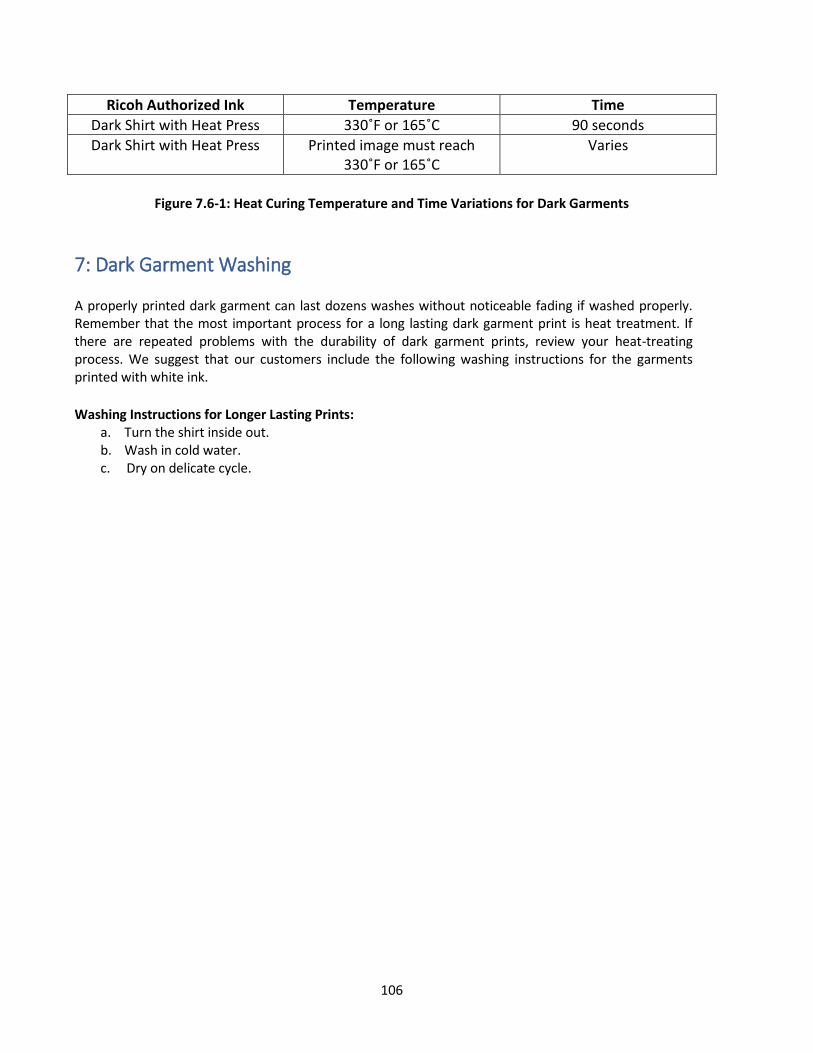
106
Ricoh Authorized Ink Temperature Time
Dark Shirt with Heat Press 330˚F or 165˚C 90 seconds
Dark Shirt with Heat Press Printed image must reach 330˚F or 165˚C
Varies
Figure 7.6-1: Heat Curing Temperature and Time Variations for Dark Garments
7: Dark Garment Washing A properly printed dark garment can last dozens washes without noticeable fading if washed properly. Remember that the most important process for a long lasting dark garment print is heat treatment. If there are repeated problems with the durability of dark garment prints, review your heat-treating process. We suggest that our customers include the following washing instructions for the garments printed with white ink.
Washing Instructions for Longer Lasting Prints:
a. Turn the shirt inside out. b. Wash in cold water. c. Dry on delicate cycle.
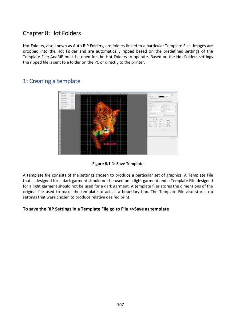
107
Chapter 8: Hot Folders Hot Folders, also known as Auto RIP Folders, are folders linked to a particular Template File. Images are dropped into the Hot Folder and are automatically ripped based on the predefined settings of the Template File; AnaRIP must be open for the Hot Folders to operate. Based on the Hot Folders settings the ripped file is sent to a folder on the PC or directly to the printer.
1: Creating a template
Figure 8.1-1: Save Template
A template file consists of the settings chosen to produce a particular set of graphics. A Template File that is designed for a dark garment should not be used on a light garment and a Template File designed for a light garment should not be used for a dark garment. A template files stores the dimensions of the original file used to make the template to act as a boundary box. The Template File also stores rip settings that were chosen to produce relative desired print.
To save the RIP Settings in a Template File go to File >>Save as template

108
2: Establish Hot Folder Location
Figure 8.2-1: Create Folders
Hot Folders require a location on a host computer for AnaRIP to RIP files from and may require additional folders to send the original image file to and a folder to send complete ripped files to.
3: Define Holder Folder Settings
Figure 8.3-1 Edit AutoRIP Folders Figure 8.3-2 Create New AutoRIP
Folder
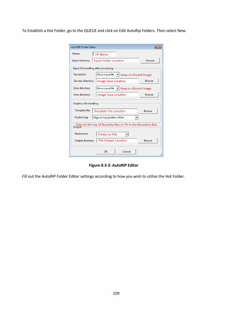
109
To Establish a Hot Folder, go to the QUEUE and click on Edit AutoRip Folders. Then select New.
Figure 8.3-3: AutoRIP Editor
Fill out the AutoRIP Folder Editor settings according to how you wish to utilize the Hot Folder.

110
Figure 8.3-4 Input File handling
The Input file handling after process section dictates what to do with the original Input File, delete or move to a new folder location.
Figure 8.3-5 and Figure 8.3-6: Graphic File Handling
Figure 8.3-5 Figure 8.3-6

111
The Graphic file handling section what determines what changes are applied within the RIP. As previously stated, the template file contains all relevant RIP information, image offsets, scaling, Underbase variables and color adjustment variables. Based on the positioning setting, Align to top position offset, Fit in placement box, aligned to top, Fit in placement box, centered, the graphic will be positioned differently in the print output. Align to top position offset, offsets the placement of the new graphic to the vertical offset of the graphic used to make the template file. Fit in Placement box, aligned to top scales the image and aligns the image to the vertical offset of the graphic used to make the template file. Fit in Placement box, centered scales the image and centers the image based on the size of the graphic used to make the template file.
Figure 8.3-7 and Figure 8.3-8: AutoRIP Output
Figure 8.3-7
Figure 8.3-8
The Output section directs where the graphics will be sent to. You can choose to either send the files to printer as save them to a folder location on the PC.

112
Figure 8.3-9 Enable AutoRIP Output Once the RIP settings have been established make sure to enable Hot Folders by double clicking on the Hot Folders’ name. The Hot Folders can also be used as driver to send already ripped files to a designated destination. Already ripped folders maintain their original when being sent via a hot folder.

113
Chapter 9: Maintenance and Transportation
• Keep infants away from polythene materials (bags, etc.) used to wrap options and cartridges/bottles for ink, cleaning solution, HV storage solution, and pretreatment liquid. Suffocation may result if polythene materials are brought into contact with the mouth or nose.
• When swallowing or inhaling ink, cleaning solution, HV storage solution or pretreatment liquid, or when getting them in the eye, follow the guidance in the appropriate safety data sheet (SDS). Download the SDS from the AnaJet website at http://anajet.com/technical-documentation • Place ink, cleaning solution, HV storage solution, and pretreatment liquid in a cool, well-ventilated place out of the reach of children. • Keep waste ink, containers for ink, cleaning solution, HV storage solution, and pretreatment liquid, and components that have been in contact with ink out of the reach of children. • When handling ink, cleaning solution, HV storage solution, or pretreatment liquid, avoid getting anything on your clothing. If you do, wash the stained area with cold water. • When replacing the cartridge for ink, cleaning solution, HV storage solution, or pretreatment liquid, avoid getting anything on your clothing. If you do, wash the stained area with cold water. • When replacing the cartridge for ink, cleaning solution, HV storage solution, or pretreatment liquid, avoid getting anything on your skin. If you do, wash the affected area thoroughly with soap and water. • When removing the cartridge for ink, cleaning solution, HV storage solution, or pretreatment liquid, avoid putting your hand near the location in which the cartridge is installed (such as the ink supply nozzle and its surrounding areas). If you get anything on your hands, wash them thoroughly with soap and water. • The ink cartridge surface may have ink on it, so be careful to avoid ink stains. • Do not disassemble the cartridge for ink, cleaning solution, HV storage solution, or pretreatment liquid. Doing so could leave ink stains or cleaning solution on your hands and fingers. • When shaking the cartridge for ink, cleaning solution, HV storage solution, or pretreatment liquid, be careful about safety of your surroundings and ink stains. Otherwise, injury or stains on household items may result. • When maintenance is performed, the carriage may move while the top cover is open. Do not touch the carriage while it is moving. Touching it may result in injury. • When performing maintenance on the machine, such as cleaning the print-head or its surrounding areas, be sure to wear commercially available goggles and gloves. • Before installing or removing options, always turn off the power switch on rear of the machine.

114
•Before opening the top cover, please turn off the power switch on the back of the machine and open it. Opening the cover without turning off the power may cause the machine to operate and cause injury. • When opening and closing the top cover, be sure to hold the handle. Be careful so that your hand or any other part of your body is not caught with the top cover.
• After opening the top cover, use the prop to keep the cover raised so that it does not close unexpectedly. Otherwise, your hand caught may be caught between the cover and the machine. • Make sure that the top cover is closed, then turn on the power switch on the back of the machine. Before closing the cover, turning on the power may cause the machine to operate and cause injury. • Follow the procedures in the user's manual for maintenance and securely install parts and covers. Failure to do reliable work may cause injury or malfunction. • When using a flat head screwdriver, be careful so that the tip of the flat head screwdriver does not hurt you.
1: Technical Notes on White Ink Maintenance Virtually all white inks used in digital apparel printers today use Titanium Dioxide for pigment. This pigment is a relatively heavy material. For direct to garment printers using Titanium Dioxide based White Inks, the following three conditions have to be met to ensure proper ink flow continues in the inkjet printer system: The inks must be agitated daily. This involves gentle shaking of the cartridges. The inks must flow through the ink delivery system frequently. This involves daily printing with white ink or daily Nozzle Checks followed by Print Head Cleans when Nozzle Checks are below 90% The inks must not touch open air; otherwise the Titanium Dioxide based ink will agglomerate and clog the ink delivery system and Print Head. RICOH Ri 3000/Ri 6000 printers use sealed ink cartridges protect inks. Open ink bottles or refillable bulk ink cartridges will expose the ink to open air causing agglomeration.

115
The Ri 3000 and Ri 6000uses a Closed-Loop Ink Delivery system with sealed ink cartridges which when properly maintained prevents inks’ exposure to air. However, the system operator still must shake the ink cartridges daily, and make the inks move through the ink tubes daily. Ri 3000 and Ri 6000 Auto circulation function reduces the manual maintenance tasks, but the operator needs to perform frequent nozzle checks and also provide the necessary additional manual maintenance.
2: Maintenance Schedule DAILY MAINTENANCE: Using the Ri 3000 or Ri 6000 Control Panel, print a Nozzle Check daily (see chapter 2: section 7). Perform Print Head cleans as needed. Usually one or two Print Head Cleans will clear the nozzles and achieve a good Nozzle Check Pattern. Generally each of the ink channels must have 90% or better Nozzle Check Patterns to achieve acceptable print quality.
Wipe the wiper blade clean at the beginning of the day. See section 9.3 Required Maintenance
Remove the 2 white ink cartridges and shake them a few times gently to keep the pigment in solution. Replace them in the same ink bays.
If you do not use white ink often or use the white ink heavily, it may be necessary to do the weekly maintenance on a daily basis or more frequently than once or twice a week.
WEEKLY MAINTENANCE:
Check the Wiper Blade, Maintenance Station and Print Head Nozzle Plate for ink residue and clean them as needed with Cleaning Solution. (You may need to clean these areas more than once or twice a week depending on your usage pattern.) See Section 9.3. Required Maintenance.
Check the left Drip Absorber for excessive buildup or saturation and replace pads or clean as necessary.
BI-WEEKLY MAINTENANCE:
Check the right Drip Absorber for excessive buildup or saturation and replace pads or clean as necessary
MONTHLY MAINTENANCE:
Check the Wiper Blade for wear and replace if needed.
Check the Wiper Holder build up and clean if necessary.
Check the Waste Ink Tank and drain as needed.
Check the fan filters and replace if entire pad becomes purple

116
EVERY 3 MONTHS: Replace all ink cartridges with Cleaning Solution cartridges and perform the Startup Fill function from the control panel until all the ink in the tubes is replaced by Cleaning Solution. Let it sit overnight. Reinstall the ink cartridges and perform the Startup Fill functions until the Cleaning Solution is completely replaced by ink in the tubes.
If a printer is not going to be used for more than one week, it is recommended to replace the ink
with Cleaning Solution. Please contact technical support if you are unclear these idle time precautions.
The printer firmware at times may need to be updated. Check for updates on www.AnaJet.com/downloads or contact your RICOH Ri 3000/Ri 6000 distributor for more information.
Print and use the MAINTENANCE CHECKLIST included in Appendix 2.
Reference the maintenance guide located on the inside of the printer
Figure 9.2-1: Maintenance Guide If You Cannot Perform Daily Regular Maintenance Do not be concerned if you cannot perform the daily white ink maintenance over the weekend. If you are not able to do the recommended regular maintenance for more than 8 days in a row, due to holidays, Vacations or emergencies replace the inks in the printer with Cleaning Solution and flush the ink delivery system of ink. When you return, replace the Cleaning Solution with inks.
3: Required Maintenance
Inkjet printers used for apparel printing require a higher level of maintenance than those used for document printing. The greater rate of ink flow, lint from garments, ink pigments and low humidity all contribute to accumulation of foreign elements in the Maintenance station, Wiper Blade, and Print Head areas. If not cleaned regularly, these residues will allow air to come in contact with these areas, and interfere with ink flow, resulting in lower quality prints and shorter life of the Print Head. If desired wear powder-free latex or rubber gloves during cleaning.

117
Record your maintenance using the maintenance checklist included in Appendix 2 The entire cleaning operation will take no more than 10 to 15 minutes. Do not take a break during this process as you will be exposing the Print Heads to air for an extended time.
Before the cleaning operation, obtain the Cleaning applicators. These are low lint urethane cleaning swabs made for RICOH Ri 3000/Ri 6000 Maintenance cleaning. Discard Soiled Cleaning Applicators after use. We also recommend some lint free wipes, Ricoh authorized Cleaning Solution and lubricant.
Figure 9.3-1: Cleaning Supplies
Cleaning Procedures: Locate the Print Head Carriage and the Maintenance Station. (Figure 9.3-2)
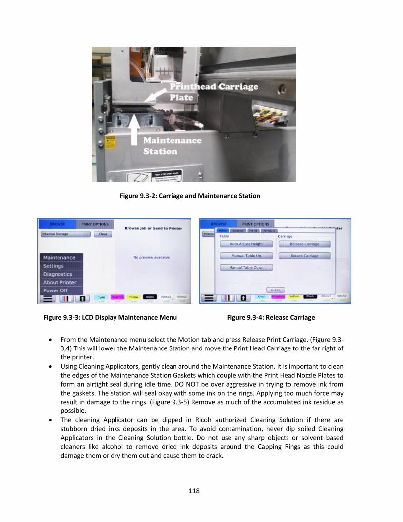
118
Figure 9.3-2: Carriage and Maintenance Station
Figure 9.3-3: LCD Display Maintenance Menu
Figure 9.3-4: Release Carriage
From the Maintenance menu select the Motion tab and press Release Print Carriage. (Figure 9.3-
3,4) This will lower the Maintenance Station and move the Print Head Carriage to the far right of the printer.
Using Cleaning Applicators, gently clean around the Maintenance Station. It is important to clean the edges of the Maintenance Station Gaskets which couple with the Print Head Nozzle Plates to form an airtight seal during idle time. DO NOT be over aggressive in trying to remove ink from the gaskets. The station will seal okay with some ink on the rings. Applying too much force may result in damage to the rings. (Figure 9.3-5) Remove as much of the accumulated ink residue as possible.
The cleaning Applicator can be dipped in Ricoh authorized Cleaning Solution if there are stubborn dried inks deposits in the area. To avoid contamination, never dip soiled Cleaning Applicators in the Cleaning Solution bottle. Do not use any sharp objects or solvent based cleaners like alcohol to remove dried ink deposits around the Capping Rings as this could damage them or dry them out and cause them to crack.
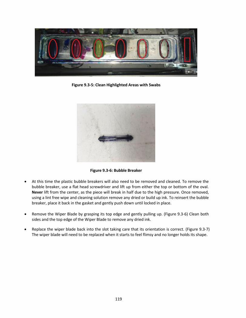
119
Figure 9.3-5: Clean Highlighted Areas with Swabs
Figure 9.3-6: Bubble Breaker
At this time the plastic bubble breakers will also need to be removed and cleaned. To remove the bubble breaker, use a flat head screwdriver and lift up from either the top or bottom of the oval. Never lift from the center, as the piece will break in half due to the high pressure. Once removed, using a lint free wipe and cleaning solution remove any dried or build up ink. To reinsert the bubble breaker, place it back in the gasket and gently push down until locked in place.
Remove the Wiper Blade by grasping its top edge and gently pulling up. (Figure 9.3-6) Clean both sides and the top edge of the Wiper Blade to remove any dried ink.
Replace the wiper blade back into the slot taking care that its orientation is correct. (Figure 9.3-7) The wiper blade will need to be replaced when it starts to feel flimsy and no longer holds its shape.

120
Figure 9.3-7: Wiper Blade Location
Figure 9.3-8: Wiper Blade Orientation
The Print Head Nozzle Plate is located below the Print Head Carriage. Center the Carriage on the carriage rail and using a small mirror to see your progress gently clean the Nozzle Plate between the Print Head edges with a new RIOCH authorized Urethane Cleaning Applicator or Lint Free wipes.
Do not use any solvent based cleaners or isopropyl alcohol as they may damage the protective coating on the print head, instead you may use Ricoh authorized Cleaning Solution.
Remove any ink residue accumulated on the Nozzle Plate. (Figure 9.3-8) When the Print Head Plate is clean you should see the bare metal of the plate. Use care when cleaning the Nozzle Plate so as not to scratch or touch the Print Heads. If dented or scratched, the Print Heads become unusable.
Figure 9.3-9: Cleaning Print Head Nozzle Plate

121
Figure 9.3-10: Cleaning Print Heads
Print heads should only be cleaned with Ricoh authorized Urethane Cleaning Applicator and Cleaning Solution. To clean the print heads, gently wipe the nozzle with light pressure
Figure 9.3-11: Flushing the Maintenance Station
When flushing the maintenance station, we will need to activate the maintenance station pump while the carriage is released. To turn on the pump we will be using the Advanced Menu.
Figure 9.3-12: Advanced menu
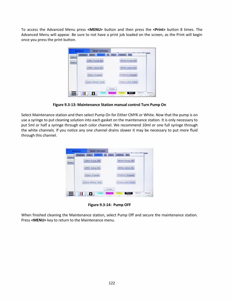
122
To access the Advanced Menu press <MENU> button and then press the <Print> button 8 times. The Advanced Menu will appear. Be sure to not have a print job loaded on the screen, as the Print will begin once you press the print button.
Figure 9.3-13: Maintenance Station manual control Turn Pump On Select Maintenance station and then select Pump On for Either CMYK or White. Now that the pump is on use a syringe to put cleaning solution into each gasket on the maintenance station. It is only necessary to put 5ml or half a syringe through each color channel. We recommend 10ml or one full syringe through the white channels. If you notice any one channel drains slower it may be necessary to put more fluid through this channel.
Figure 9.3-14: Pump OFF When finished cleaning the Maintenance station, select Pump Off and secure the maintenance station. Press <MENU> key to return to the Maintenance menu.
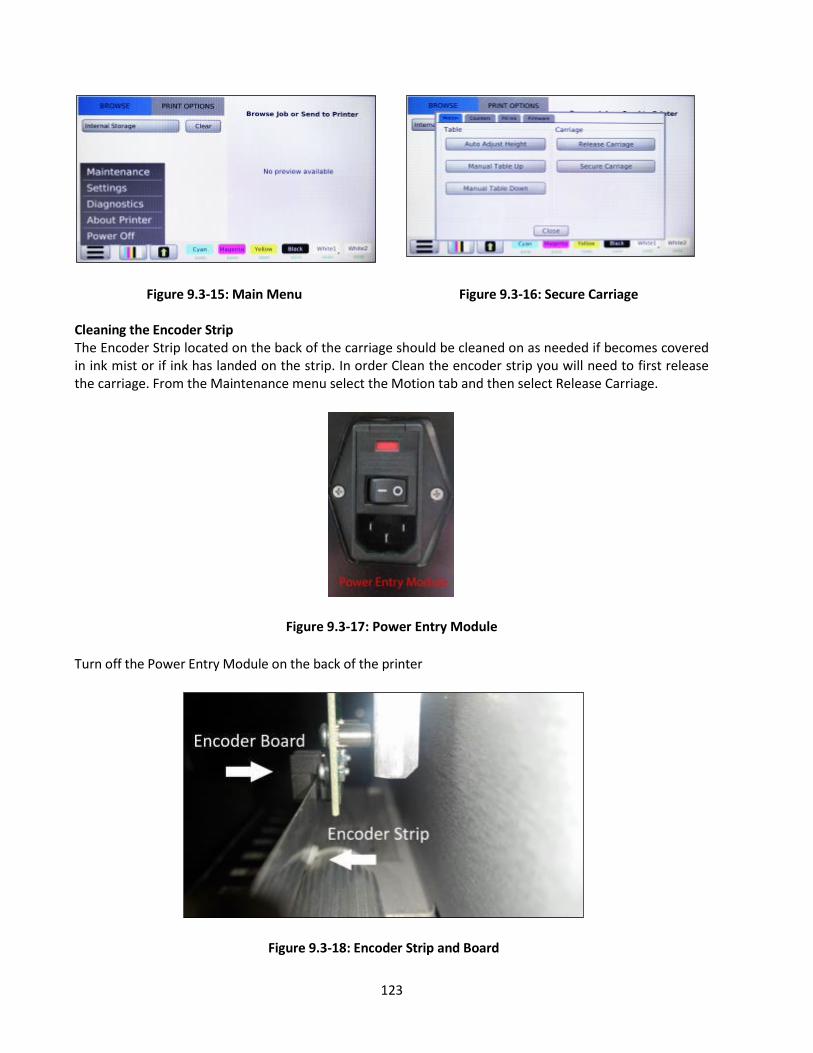
123
Figure 9.3-15: Main Menu Figure 9.3-16: Secure Carriage
Cleaning the Encoder Strip The Encoder Strip located on the back of the carriage should be cleaned on as needed if becomes covered in ink mist or if ink has landed on the strip. In order Clean the encoder strip you will need to first release the carriage. From the Maintenance menu select the Motion tab and then select Release Carriage.
Figure 9.3-17: Power Entry Module
Turn off the Power Entry Module on the back of the printer
Figure 9.3-18: Encoder Strip and Board

124
If the cleaning the inside of the encoder board is needed to remove any lint, gently remover the encoder strip from the encoder board and thread a lint free wipe through the sensor. Cleaning with a lint free wipe and 91% isopropyl alcohol will help remove any ink mist that has gotten on the sensor. Dry the encoder board, the place the encoder strip back in the encoder board sensor slot. Turn on the Power Entry Module and press the power button the front of the control panel. If the encoder strip was not put back in the sensor, encoder failure error will be displayed.
Figure 9.3-19: Encoder Failure
4: Ink Levels and Cart Replacement When an ink cartridge low or empty, a message will display on the control panel, the LCD panel will display on the affected ink channel, “INK LOW, VERY LOW, EMPTY”. The ink cartridge should be replaced as soon as the LCD display reads “VERY LOW”. If the LCD display changes to low during a print job, the current job can be finished without any problem. When the cartridge is low the INK LOW warning will appear when 20% of the ink is left. This will give you time to order ink if you do not have a replacement cartridge. Once an ink cartridge reads EMPTY the printer will display “Not all ink cartridges in a ready state!”

125
Figure 9.4-1: Ink Cartridge Problem
Replace the ink cart that stated shown to be Very Low or Empty. Once replaced, select the color replaced to recalibrate the printer reading.
Figure 9.4-2: Ink Empty Message

126
Figure 9.4-3: Ink Cartridge Depleted Message
The ink empty message will appear when the cartridge reads empty. There will be a small buffer of 1- prints to continue printing. After the 10th print, the ignore button will no longer become disabled. However, once that limit has been reach the machine will no longer allow prints to be performed until the specific empty cartridge has been replaced with a new cartridge. If the LCD control panel display still reads “NOT FOUND” after a new cartridge is installed, it may be installed improperly. Pull out the cartridge and insert it carefully but fully until it stops. Do not force the cartridge to avoid any damage to the printer. Please note that without installing all 6 cartridges, the printer will not print. Even when you do not use the printer for an extended period of time, do not remove the ink cartridges from the printer. Even if the ink cartridges are empty, keep the cartridges installed to help keep air away from the ink delivery system. For Printer storage for an extended time period, it is recommended to flush ink carts with Cleaning Solution then replace then with HV storage solution. See section 9.5. Switching from Ink to Cleaning Solution Using the Startup Fill Function Ricoh recommends the use of Ricoh authorized Ink cartridges which have been specifically developed for the RICOH Ri 3000 and RICOH Ri 6000 printer. Use of other inks or tampering of the ink cartridge will not only produce poor quality prints but may damage your printer. Ricoh is not responsible for any damaged caused to the printer through the use of third party inks. If you do not have a replacement cartridge, leave the old cartridge in the printer until you are ready to replace it with a new one. If a non-Ricoh authorized ink cartridge is used, the error message “NOT FOUND” will appear. In addition, a pop-up error message will appear stating, “Authorized cart not found, Unauthorized product may damage your machine, to continue press “ignore” otherwise “cancel.”

127
Figure 9.4-4: Unauthorized Ink Message
To replace ink cartridges Once the LCD control panel has indicated a cartridge is low or empty replace using the correct color into the correct ink bay slot, or you will not be able to continue printing. Cartridge color assignment is located above the ink bay with a matching colored circle. (Figure 9.4-4)
Figure 9.4-5: Ink Bay Cartridge Order
Figure 9.4-6: Ink Bay Cartridge Orientation
Carefully pull the empty cartridge straight out of the Ink Bay. (Figure 9.4-7) The LCD on the control panel will read “NOT FOUND” for the missing cartridge.
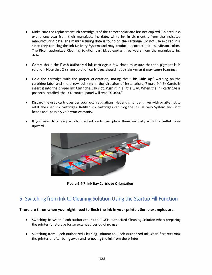
128
Make sure the replacement ink cartridge is of the correct color and has not expired. Colored inks expire one year from their manufacturing date, white ink in six months from the indicated manufacturing date. The manufacturing date is found on the cartridge. Do not use expired inks since they can clog the Ink Delivery System and may produce incorrect and less vibrant colors. The Ricoh authorized Cleaning Solution cartridges expire three years from the manufacturing date.
Gently shake the Ricoh authorized ink cartridge a few times to assure that the pigment is in solution. Note that Cleaning Solution cartridges should not be shaken as it may cause foaming.
Hold the cartridge with the proper orientation, noting the “This Side Up” warning on the cartridge label and the arrow pointing in the direction of installation. (Figure 9.4-6) Carefully insert it into the proper Ink Cartridge Bay slot. Push it in all the way. When the ink cartridge is properly installed, the LCD control panel will read “GOOD.”
Discard the used cartridges per your local regulations. Never dismantle, tinker with or attempt to refill the used ink cartridges. Refilled ink cartridges can clog the Ink Delivery System and Print heads and possibly void your warranty.
If you need to store partially used ink cartridges place them vertically with the outlet valve upward.
Figure 9.4-7: Ink Bay Cartridge Orientation
5: Switching from Ink to Cleaning Solution Using the Startup Fill Function There are times when you might need to flush the ink in your printer. Some examples are:
Switching between Ricoh authorized ink to RIOCH authorized Cleaning Solution when preparing the printer for storage for an extended period of no use.
Switching from Ricoh authorized Cleaning Solution to Ricoh authorized ink when first receiving the printer or after being away and removing the ink from the printer
129
The Replacement Process
Remove all ink cartridges from your printer’s ink bay.
Press <MENU> again and Maintenance followed by Start Up Fill. Select to Fill CMYK WW ink lines.
Once inside of the ink fill menu, choose long. Open the lid to see the white ink exit the ink tubes. It will take several of these long fills to completely empty the white lines of white ink. Do at least 3 long fills. If ink is still visible in the purge lines after three fills, continue until the lines are empty. The Purge lines go to the BACK of the white print head. The print lines go to the FRONT of the print head.
After flushing the ink system, install all six cleaning fluid cartridges into the printer and once again select CMYKWW Lines. Fill for one long fill and one short fill. Additional fills may be required if the print lines are not completely filled with cleaning solution.
Continue running the fills until the purge and print lines are crystal clear. The Ricoh authorized cleaning solution is clear and the ink does not stain the tubes so lines which have been flushed thoroughly are completely transparent.
Once the flush is complete, go through the weekly maintenance routine. Clean the nozzle plate, the rubber seals on the maintenance station and wiper blade. Then, print a nozzle check onto a piece of paper. The nozzle check should print clear without any tint of color. If you see ink still in the nozzle check, continue flushing until the nozzle check prints clear.
6: Waste Ink Tank and Drip Absorbers Emptying the Waste Ink Tank The printer’s waste inks are collected in the Waste Ink Tank, located at the inside back right of the printer. When it needs to be emptied a message will appear on the display when you send a print job or Print Head clean. (Figure 9.6-1). At this time, you may select No and empty it then or select Yes and empty the tank later. Waste ink is emptied through the Waste Ink Drain on the back of the printer.

130
Follow the procedure below to remove the waste ink:
Figure 9.6-1: Waste Tank Full Message
Remove the Waste Ink Drain Tube from the storage area located inside the printer next to the waste ink tank (See Figure 9.6-3).
Figure 9.6-2: Waste Ink Tank and Reservoir Ink Tank Location
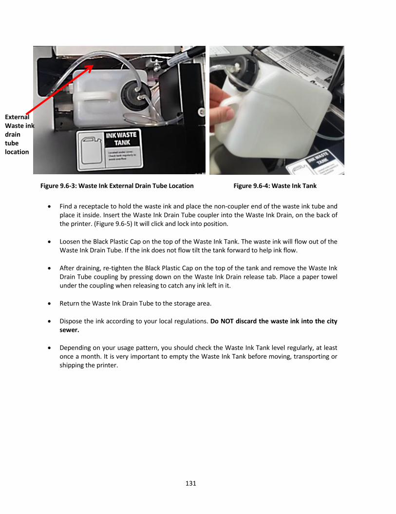
131
Figure 9.6-3: Waste Ink External Drain Tube Location Figure 9.6-4: Waste Ink Tank
Find a receptacle to hold the waste ink and place the non-coupler end of the waste ink tube and
place it inside. Insert the Waste Ink Drain Tube coupler into the Waste Ink Drain, on the back of the printer. (Figure 9.6-5) It will click and lock into position.
Loosen the Black Plastic Cap on the top of the Waste Ink Tank. The waste ink will flow out of the Waste Ink Drain Tube. If the ink does not flow tilt the tank forward to help ink flow.
After draining, re-tighten the Black Plastic Cap on the top of the tank and remove the Waste Ink Drain Tube coupling by pressing down on the Waste Ink Drain release tab. Place a paper towel under the coupling when releasing to catch any ink left in it.
Return the Waste Ink Drain Tube to the storage area.
Dispose the ink according to your local regulations. Do NOT discard the waste ink into the city sewer.
Depending on your usage pattern, you should check the Waste Ink Tank level regularly, at least once a month. It is very important to empty the Waste Ink Tank before moving, transporting or shipping the printer.
External Waste ink drain tube location
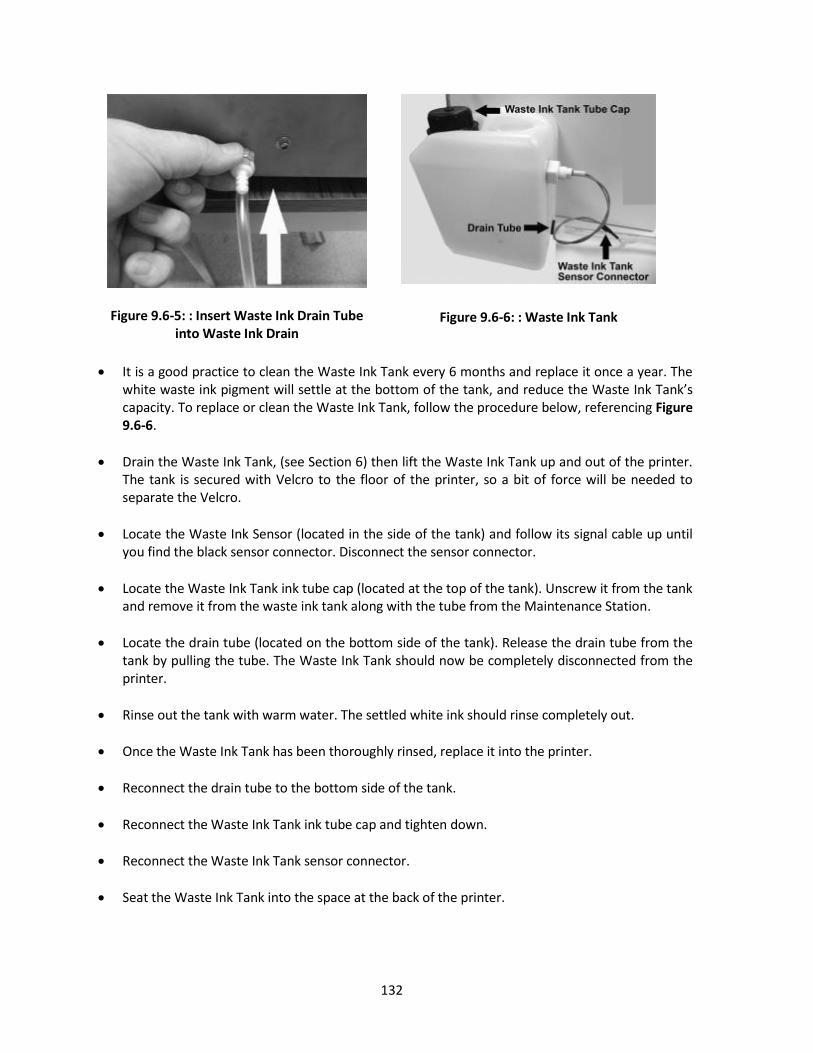
132
Figure 9.6-5: : Insert Waste Ink Drain Tube
into Waste Ink Drain
Figure 9.6-6: : Waste Ink Tank
It is a good practice to clean the Waste Ink Tank every 6 months and replace it once a year. The
white waste ink pigment will settle at the bottom of the tank, and reduce the Waste Ink Tank’s capacity. To replace or clean the Waste Ink Tank, follow the procedure below, referencing Figure 9.6-6.
Drain the Waste Ink Tank, (see Section 6) then lift the Waste Ink Tank up and out of the printer. The tank is secured with Velcro to the floor of the printer, so a bit of force will be needed to separate the Velcro.
Locate the Waste Ink Sensor (located in the side of the tank) and follow its signal cable up until you find the black sensor connector. Disconnect the sensor connector.
Locate the Waste Ink Tank ink tube cap (located at the top of the tank). Unscrew it from the tank and remove it from the waste ink tank along with the tube from the Maintenance Station.
Locate the drain tube (located on the bottom side of the tank). Release the drain tube from the tank by pulling the tube. The Waste Ink Tank should now be completely disconnected from the printer.
Rinse out the tank with warm water. The settled white ink should rinse completely out.
Once the Waste Ink Tank has been thoroughly rinsed, replace it into the printer.
Reconnect the drain tube to the bottom side of the tank.
Reconnect the Waste Ink Tank ink tube cap and tighten down.
Reconnect the Waste Ink Tank sensor connector.
Seat the Waste Ink Tank into the space at the back of the printer.

133
Checking and Emptying the Waste Reservoir Tank There is an overflow reservoir tank located under the ink mist cover. This tank should be checked monthly and emptied. This tank does not have a sensor, so it is very important to check it on a monthly basis. The tank is attached by Velcro. Pull out the tube and carefully remove the tank. Unscrew the cap and pour out the waste ink. When flushing out the system, be sure to rinse this tank out after removing the waste ink.
Checking and Replacing the Drip Absorber Check the Drip Absorber located on the left and right sides of the printer regularly. (Figures 9.6-7 and 9.6-8) Replace them as needed when they are soaked with ink or excessive ink residue builds up. If you use a lot of white ink, you will have a more rapid buildup of ink residue. If you do not have a new Drip Absorber to replace, you can re-use the Drip Absorber by washing it with warm water. Dry the foam thoroughly before reinstalling it.
Figure 9.6-7: Right Side Drip Absorber
Figure 9.6-8: Left Side Ink Drip Absorber Tray The Drip Absorber on the left side of the printer is located under the Maintenance Station. The foam tray must be removed for inspection or replacement. (Figure 9.6-7)

134
To remove the left drip absorber tray, the table must be moved all the way out to the home position and the 2 screws must be removed so the tray can be pulled out.
7: Changing Fan Filters To replace the fan filter, remove fan cover and replace filter. After swapping the filter, put the fan cover back in place.
Figure 9.7-1:Replace Fan Filter
Figure 9.7-2: New Fan Filter
8: Cleaning the Printer
Clean the printer a few times a year to keep the printer operating properly.
While cleaning, be careful not touch or soil any of the pulleys, the belt and the Carriage Encoder Strip located behind the Print Head Carriage movement area.
Never use any solvent to clean the printer. These chemicals can damage the printer components.
Do not use a hard or abrasive brush.
Do not lubricate the inside of the printer. Unsuitable oil or lubricants can damage the mechanisms. Contact a qualified RICOH Ri 3000/Ri 6000 service technician if lubrication is needed.

135
The Printer Cleaning Process Turn off the print engine power using the <POWER> key on the Control Panel. When the print
engine power down sequence is completed, turn off the Main Power Switch at the rear of the printer.
Open the printer top cover.
Using a soft brush, clean away any dust and dirt inside the printer.
Clean the Maintenance Station, Wiper Blade and around the Nozzle Plate with Cleaning Applicators as described in section 3 of this chapter.
Drain the Waste Ink Tank as needed. Refer to section 9.6 of this chapter.
Close the printer top cover.
If the outer cover is dirty, clean it with a soft damp cloth with mild detergent. Make sure the water does not seep into the printer’s mechanisms.
Using a damp cloth, clean the Print Table with mild detergent. Do not use ammonia based glass cleaners such as Windex as the ammonia can dry and damage the Print Head.
9: Transporting the Printer Very Short Distance Move To move the printer a very short distance, with the printer remaining at a horizontal position, follow the steps below. An example of such a move would be moving the printer within a building. If you need to move the printer a longer distance or ship it through a common carrier, follow the instructions for Short Distance or Long Distance.
Turn off the print engine by pressing the <POWER> key on the Control Panel. When the print engine completes its power down sequence, switch off the printer Main Power Switch on the rear of the printer.
Drain the Waste Ink Tank. (See Section 9.6 of this chapter)
Clean and drain the Left Drip Absorber
Remove both the power cord and USB cable.
The ink cartridges should remain in place. Removing ink cartridge may cause ink dry-out in the ink delivery system.
Install the Carriage and Table Retainers that where with the printer when it arrived. Use the Thumb Screw to tighten the table retainers. (See figure 9.9-1)

136
Figure 9.9-1: It is important to place the Table and Carriage Retainer before Transport.
Move the printer carefully (four people are required). Keep the printer horizontal. Only move the printer on its side when moving through a doorway.
When you reach the new destination, make certain the printer is placed on a stable, sturdy and level table. Make sure the printer is level using a “torpedo level” as described in Chapter 2: Startup of a New Printer, Section 4: Setting up the Printer.
Make sure that the environment of the new location meets to the printer’s requirements. See Chapter 1: Product Information, Section 2. Operation Environment Requirements.
Short Distance Move A short distance move involves moving the printer by a vehicle under your supervision, the actual travel time should not take more than an hour or two.
If traveling through a high temperature or very low humidity area, or if there is a large altitude
change, replace all of the ink with Cleaning Solution. (See Section 9.5 of this chapter).
If you are moving the printer in the original printer box replace all of the ink with Cleaning Solution. (See Section 9.6 of this chapter). This is necessary because the cartridges must be removed for the printer to fit into the box.
Drain the Waste Ink Tank. (See Section 9.6 of this chapter)
Keep the ink cartridges in place. Do not leave the printer without the ink cartridges or Cleaning Solution in place. Otherwise replace ink with Cleaning Solution. (See Section 9.5 of this chapter)
At the new destination, replace the ink if needed. (See Section 9.5 of this chapter) and check the printer performance. Perform a Print Head Nozzle Check and clean the Print Head as needed to restore good ink flow. (See Chapter 2 Startup of a New Printer, Section 7. Performing a Nozzle Check) Leaving the printer for a long time without restoring good ink flow may cause difficulties with the ink flow later.
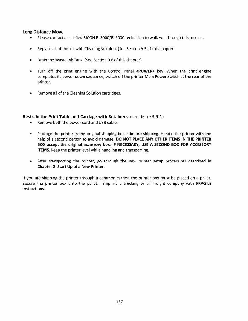
137
Long Distance Move Please contact a certified RICOH Ri 3000/Ri 6000 technician to walk you through this process.
Replace all of the ink with Cleaning Solution. (See Section 9.5 of this chapter)
Drain the Waste Ink Tank. (See Section 9.6 of this chapter)
Turn off the print engine with the Control Panel <POWER> key. When the print engine completes its power down sequence, switch off the printer Main Power Switch at the rear of the printer.
Remove all of the Cleaning Solution cartridges.
Restrain the Print Table and Carriage with Retainers. (see figure 9.9-1)
Remove both the power cord and USB cable.
Package the printer in the original shipping boxes before shipping. Handle the printer with the help of a second person to avoid damage. DO NOT PLACE ANY OTHER ITEMS IN THE PRINTER BOX accept the original accessory box. IF NECESSARY, USE A SECOND BOX FOR ACCESSORY ITEMS. Keep the printer level while handling and transporting.
After transporting the printer, go through the new printer setup procedures described in Chapter 2: Start Up of a New Printer.
If you are shipping the printer through a common carrier, the printer box must be placed on a pallet. Secure the printer box onto the pallet. Ship via a trucking or air freight company with FRAGILE instructions.
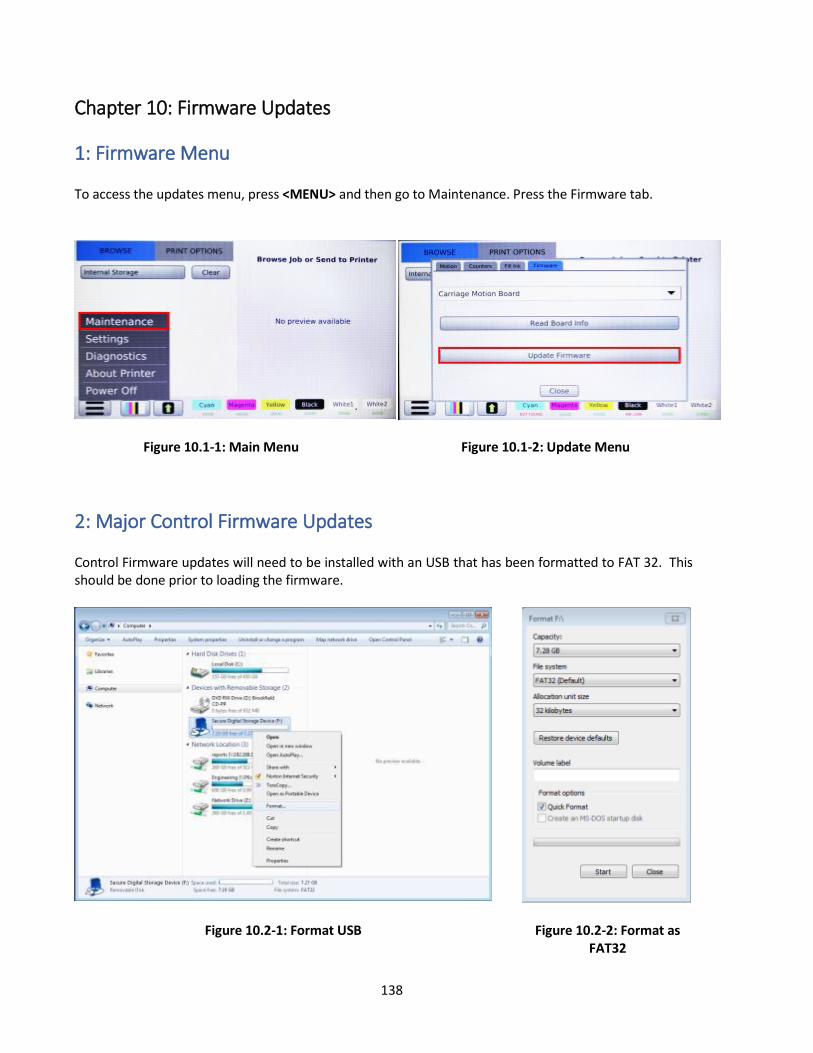
138
Chapter 10: Firmware Updates
1: Firmware Menu To access the updates menu, press <MENU> and then go to Maintenance. Press the Firmware tab.
Figure 10.1-1: Main Menu
Figure 10.1-2: Update Menu
2: Major Control Firmware Updates Control Firmware updates will need to be installed with an USB that has been formatted to FAT 32. This should be done prior to loading the firmware.
Figure 10.2-1: Format USB
Figure 10.2-2: Format as FAT32
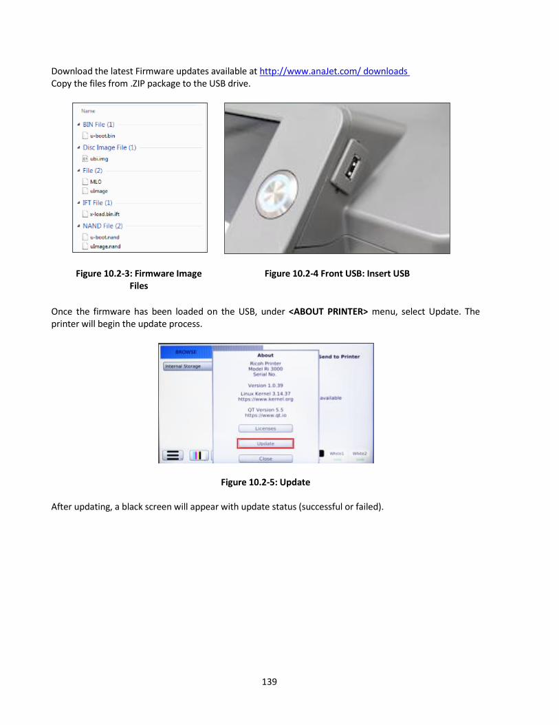
139
Download the latest Firmware updates available at http://www.anaJet.com/ downloads Copy the files from .ZIP package to the USB drive.
Figure 10.2-3: Firmware Image Files
Figure 10.2-4 Front USB: Insert USB
Once the firmware has been loaded on the USB, under <ABOUT PRINTER> menu, select Update. The printer will begin the update process.
Figure 10.2-5: Update After updating, a black screen will appear with update status (successful or failed).

140
Figure 10.2-6: Update Status Successful The update will install the firmware and verify the installation of the files. Once finished, the printer will power down. See Figure 10.2-6 for an example of the screen you will see during update. Once the USB has been removed, turn on the printer. Be sure to confirm the printer model and firmware version number located under the About Printer menu is the same as the one downloaded from the website.
Figure 10.2-7: Firmware Version Verification
Update failed multiple times If the update fails more the once, note the percentage the update failed and block number. Perform the update again and if the update fails at the same point, notify technical support. If however the update fails at a different point, try again. If Fails, it will show on a screen like Figure 10.2-8, but will say, “Update Failed”, “Not found” or “Incomplete Signature package.”

141
Figure 10.2-8: Firmware Check Points
3: Minor Control Firmware Updates Download the latest Firmware updates available at http://www.anaJet.com/downloads The minor update will consist of an update.signature and an update.zip file and can be installed with an USB Flash Drive. Copy the two files to the root the drive
Figure 10.3-1: Firmware Update Files
Insert the USB Drive. In the Maintenance menu options select Update Firmware and select the device location where the firmware is located
Figure 10.3-2: Update Control Firmware Figure 10.3-3: Update Control Firmware Select
Once the update is initiated printer will then proceed to secure itself and begin the update process

142
Figure 10.3-4: Updating Figure 10.3-5: Prepare for Update
During the update the printer will verify that the update package and signature files have been found and that it has been installed, once finished the printer will power down.
Figure 10.3-6: Update Application
Once the printer is off, power on the printer. Be sure to confirm the printer model and firmware version number displayed in the About Printer Menu as the one downloaded from the website.
Figure 10.3-7: Update Version Confirmation
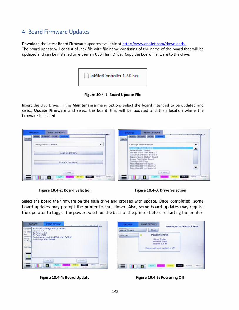
143
4: Board Firmware Updates Download the latest Board Firmware updates available at http://www.anaJet.com/downloads The board update will consist of .hex file with file name consisting of the name of the board that will be updated and can be installed on either an USB Flash Drive. Copy the board firmware to the drive.
Figure 10.4-1: Board Update File Insert the USB Drive. In the Maintenance menu options select the board intended to be updated and select Update Firmware and select the board that will be updated and then location where the firmware is located.
Figure 10.4-2: Board Selection
Figure 10.4-3: Drive Selection
Select the board the firmware on the flash drive and proceed with update. Once completed, some board updates may prompt the printer to shut down. Also, some board updates may require the operator to toggle the power switch on the back of the printer before restarting the printer.
Figure 10.4-4: Board Update
Figure 10.4-5: Powering Off

144
Once the board firmware has been installed, verify the firmware version. To verify, In the Firmware tab select the board that was updated, the select Read Board Info.
Figure 10.4-6: Board Selection Select Get Firmware Info Verify the version number of the board matches the one downloaded from the website. The printer will then need to be powered down and restarted.
Figure 10.4-7: Verify Board Firmware

145
Figure 10.4-8: Powering Off
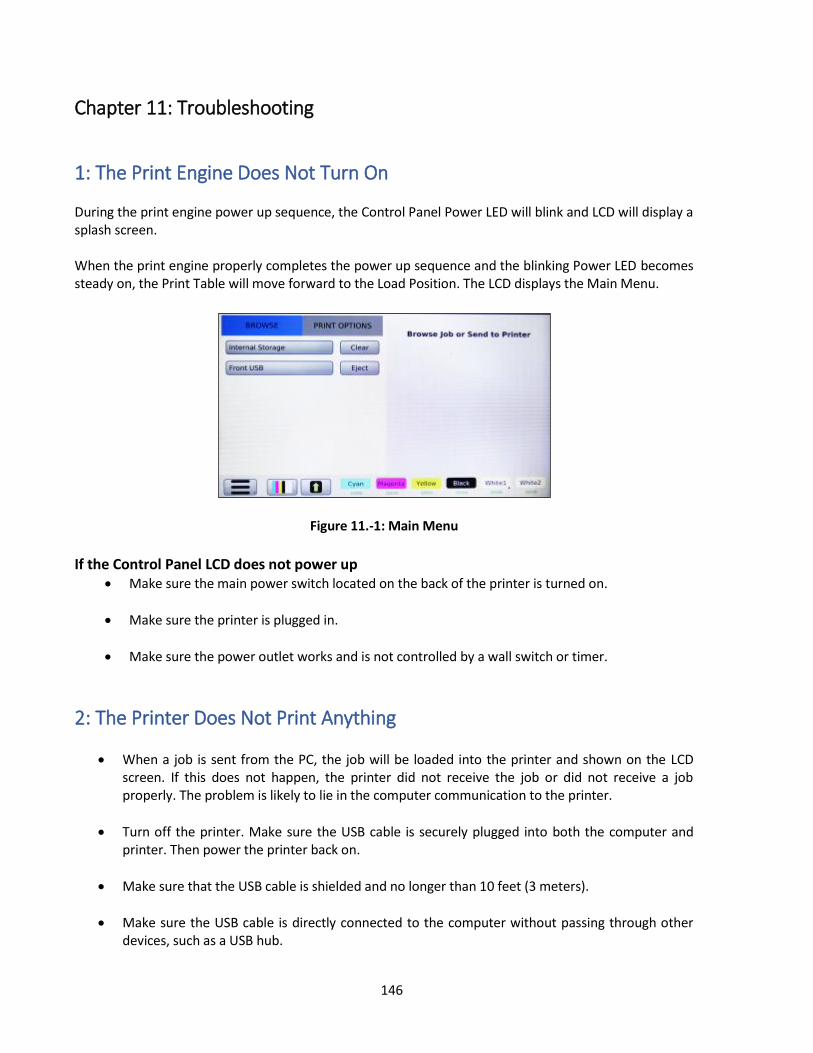
146
Chapter 11: Troubleshooting
1: The Print Engine Does Not Turn On During the print engine power up sequence, the Control Panel Power LED will blink and LCD will display a splash screen. When the print engine properly completes the power up sequence and the blinking Power LED becomes steady on, the Print Table will move forward to the Load Position. The LCD displays the Main Menu.
Figure 11.-1: Main Menu
If the Control Panel LCD does not power up
Make sure the main power switch located on the back of the printer is turned on.
Make sure the printer is plugged in.
Make sure the power outlet works and is not controlled by a wall switch or timer.
2: The Printer Does Not Print Anything
When a job is sent from the PC, the job will be loaded into the printer and shown on the LCD screen. If this does not happen, the printer did not receive the job or did not receive a job properly. The problem is likely to lie in the computer communication to the printer.
Turn off the printer. Make sure the USB cable is securely plugged into both the computer and printer. Then power the printer back on.
Make sure that the USB cable is shielded and no longer than 10 feet (3 meters).
Make sure the USB cable is directly connected to the computer without passing through other devices, such as a USB hub.
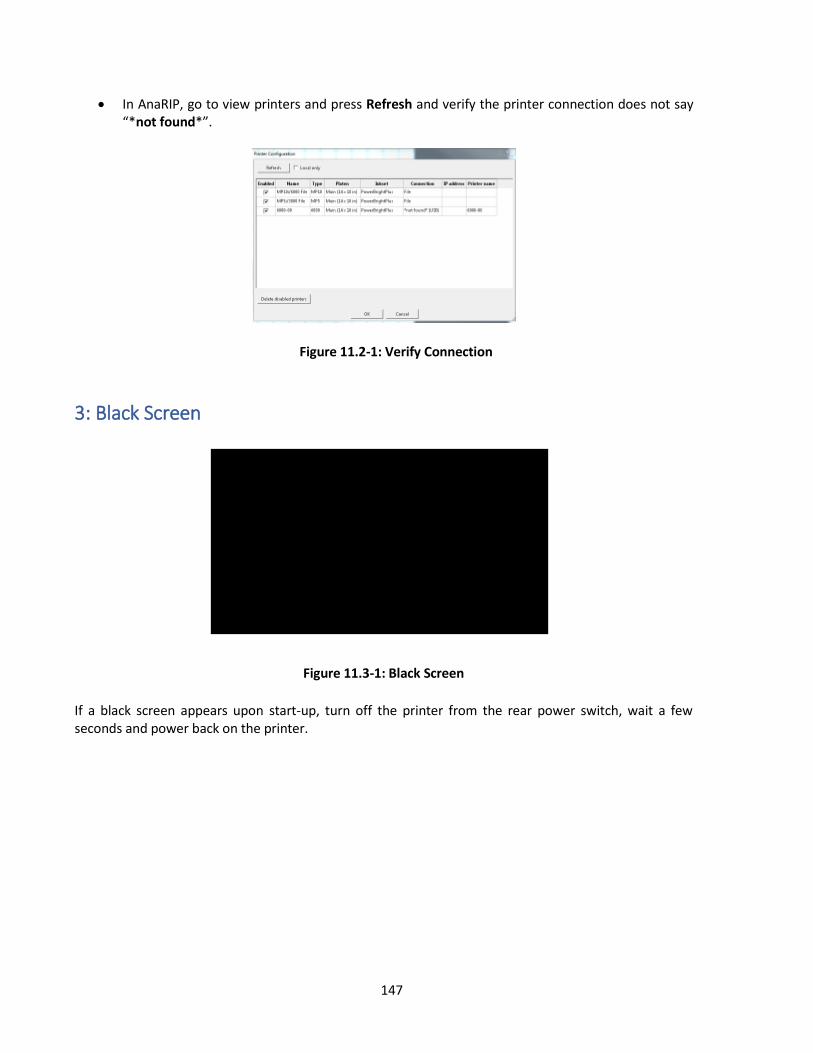
147
In AnaRIP, go to view printers and press Refresh and verify the printer connection does not say “*not found*”.
Figure 11.2-1: Verify Connection
3: Black Screen
Figure 11.3-1: Black Screen
If a black screen appears upon start-up, turn off the printer from the rear power switch, wait a few seconds and power back on the printer.

148
4: Startup Application Error
Figure 11.4-1: Application Error
If an Application error appears on startup verify the purple USB cable is connected to the Carriage Controller (located on the carriage, print head controllers plug into this) and the USB-ETH-CAN-Switch Board (located next to the waste tank). Check to make sure all the boards have power and all cables are plugged in. If there is a cable not plugged in, turn of the machine before reconnecting the cable. If all cables are confirmed to be connected, contact a certified RICOH Ri 3000/Ri 6000 technician.
5: Platform did not lower upon startup
Figure 11.5-1: Platform Startup Error
If the maintenance station platform fails to initially detect the platform sensor the control panel will display three options: Retry, Diagnose, and Ignore. Ignore function tells the printer to ignore the sensor and proceed with the boot up sequence Diagnose function has the operator perform check to verify the sensor is working Retry function moves the platform in an attempt to get the see if the sensor is recognized.

149
Figure 11.5-2 and Figure 11.5-3: Platform Startup Diagnose
Figure 11.5-2
Figure 11.5-2
Platform Diagnose The Platform diagnose function prompts the operator to observe if the maintenance station has moved up and down after the operator has moved up and down. If during diagnostic process the printer did not detect the maintenance station platform position, two different errors depending on the operator’s observance.
Figure 11.5-4: Platform Error Platform Moved
Figure 11.5-5: Platform Error Platform Did Not Move
6: Home Table Time Out If you receive a Home Table Timeout error, verify the grey CanBus cable is plugged to each of the boards of the printer. If all cables are connected and the Table motion Board (located on the back center floor of the printer) does not receive power, the table will not move upon startup and thus results in a home table time out error. Please contact a certified RICOH Ri 3000/Ri 6000 if this error occurs
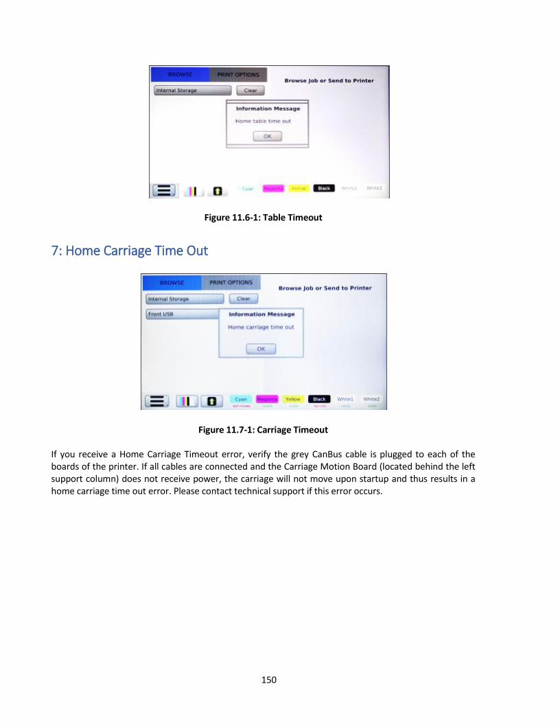
150
Figure 11.6-1: Table Timeout
7: Home Carriage Time Out
Figure 11.7-1: Carriage Timeout If you receive a Home Carriage Timeout error, verify the grey CanBus cable is plugged to each of the boards of the printer. If all cables are connected and the Carriage Motion Board (located behind the left support column) does not receive power, the carriage will not move upon startup and thus results in a home carriage time out error. Please contact technical support if this error occurs.

151
8: Platform Did Not Lower/Engage
Figure 11.8-1: Platform Error
If the maintenance station platform does not lower or rise during its normal operation, the control panel will display three options: Retry, Cancel, and Ignore
Ignore function tells the printer to ignore the sensor and proceed with the next action
Cancel function cancels any operations the operator intended to perform
Retry function moves the platform in an attempt to get the see if the sensor is recognized
Figure 11.8-2: Check Platform Limit State If the Maintenance station is not being detected, you can verify if the sensor is operating correctly in the <Diagnostics> Menu under the Exercise Motion tab.

152
Figure 11.8-3: Platform Down
Figure 11.8-4: Platform Up Limit1 should be 0 after Platform UP is selected and 1 when Platform Down is selected.
9: Failed to Calibrate Head Drive Board Voltage If the printer detects the print voltages are of out of tolerance the printer will attempt to calibrate the head drive voltage. If the printer is unable calibrate the print heads, the control panel will display a Voltage Error and prompts the operator decided whether to continue with print. Continuing with print may result in print discoloration.
Figure 11.9-1: Head Voltages Out of Tolerance Head Recalibration can be accomplished in the <Diagnostic> Menu under the Print Head tab.

153
Figure 11.9-2: Calibrate Print Heads
Figure 11.9-3: Read Head Voltages
To Recalibrate the Print Head Drive Board Voltages, in the <Diagnostics> Menu under the Print Head tab select Calibrate Head Voltages. If the Print Head Driver Board fails to calibrate, repeat a maximum of 5 times. If the boards are unable to calibrate, contact a certified RICOH Ri 3000/Ri 6000 technician.
Figure 11.9-4 Failed to Calibrate Print Heads

154
10: Horizontal Banding Since the printer creates images using a linear print process, if there are issues with nozzles not firing, these will show as bands of lighter or darker color across the image (Figure 11-10-1). To eliminate banding, follow the procedures below.
Figure 11.10-1: Example of Horizontal Banding
Run a Nozzle Check. (See Chapter 2 Startup of a New Printer, Section 7. Performing a Nozzle Check) If needed perform the necessary Print Head cleaning
Check the LCD Control Panel and check for low or empty ink cartridges if any are low or out of ink, replace with a new ink cartridge.
Open the printer cover, and check the Ink Tubes. If any of the tubes have gaps in them, it will be necessary to do a Print Head Clean. (See Chapter 2 Startup of a New Printer, Section 7. Performing a Nozzle Check)
Adjust the Print Table height to the correct level. (See Chapter 4: Printer Operation, Section 5, Adjustment of Print Table).
11: Incorrect or Missing Colors If the colors you are trying to print are wrong or not printing, try the solutions below:
Run a Nozzle Check. (See Chapter 2 Startup of a New Printer, Section 7. Performing a Nozzle Check) If needed perform the necessary Print Head cleaning.
Make sure that you are using Ricoh authorized Ink.
Check the LCD Control Panel and check for low or empty ink cartridges if any are low or out of ink, replace with a new ink cartridge.
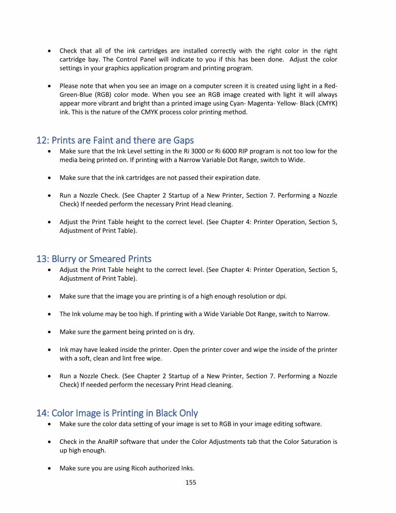
155
Check that all of the ink cartridges are installed correctly with the right color in the right cartridge bay. The Control Panel will indicate to you if this has been done. Adjust the color settings in your graphics application program and printing program.
Please note that when you see an image on a computer screen it is created using light in a Red-Green-Blue (RGB) color mode. When you see an RGB image created with light it will always appear more vibrant and bright than a printed image using Cyan- Magenta- Yellow- Black (CMYK) ink. This is the nature of the CMYK process color printing method.
12: Prints are Faint and there are Gaps Make sure that the Ink Level setting in the Ri 3000 or Ri 6000 RIP program is not too low for the
media being printed on. If printing with a Narrow Variable Dot Range, switch to Wide.
Make sure that the ink cartridges are not passed their expiration date.
Run a Nozzle Check. (See Chapter 2 Startup of a New Printer, Section 7. Performing a Nozzle Check) If needed perform the necessary Print Head cleaning.
Adjust the Print Table height to the correct level. (See Chapter 4: Printer Operation, Section 5, Adjustment of Print Table).
13: Blurry or Smeared Prints Adjust the Print Table height to the correct level. (See Chapter 4: Printer Operation, Section 5,
Adjustment of Print Table).
Make sure that the image you are printing is of a high enough resolution or dpi.
The Ink volume may be too high. If printing with a Wide Variable Dot Range, switch to Narrow.
Make sure the garment being printed on is dry.
Ink may have leaked inside the printer. Open the printer cover and wipe the inside of the printer with a soft, clean and lint free wipe.
Run a Nozzle Check. (See Chapter 2 Startup of a New Printer, Section 7. Performing a Nozzle Check) If needed perform the necessary Print Head cleaning.
14: Color Image is Printing in Black Only Make sure the color data setting of your image is set to RGB in your image editing software.
Check in the AnaRIP software that under the Color Adjustments tab that the Color Saturation is up high enough.
Make sure you are using Ricoh authorized Inks.
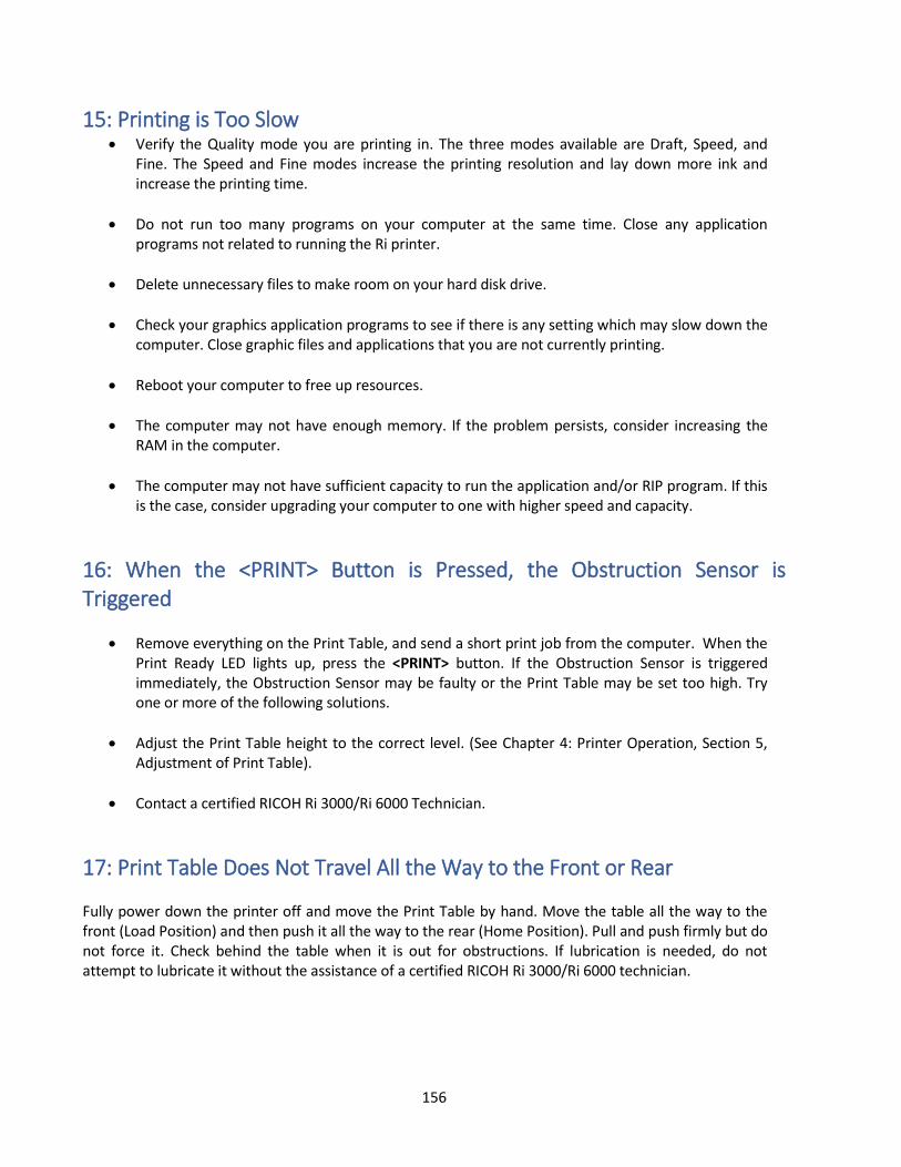
156
15: Printing is Too Slow Verify the Quality mode you are printing in. The three modes available are Draft, Speed, and
Fine. The Speed and Fine modes increase the printing resolution and lay down more ink and increase the printing time.
Do not run too many programs on your computer at the same time. Close any application programs not related to running the Ri printer.
Delete unnecessary files to make room on your hard disk drive.
Check your graphics application programs to see if there is any setting which may slow down the computer. Close graphic files and applications that you are not currently printing.
Reboot your computer to free up resources.
The computer may not have enough memory. If the problem persists, consider increasing the RAM in the computer.
The computer may not have sufficient capacity to run the application and/or RIP program. If this is the case, consider upgrading your computer to one with higher speed and capacity.
16: When the <PRINT> Button is Pressed, the Obstruction Sensor is Triggered
Remove everything on the Print Table, and send a short print job from the computer. When the Print Ready LED lights up, press the <PRINT> button. If the Obstruction Sensor is triggered immediately, the Obstruction Sensor may be faulty or the Print Table may be set too high. Try one or more of the following solutions.
Adjust the Print Table height to the correct level. (See Chapter 4: Printer Operation, Section 5, Adjustment of Print Table).
Contact a certified RICOH Ri 3000/Ri 6000 Technician.
17: Print Table Does Not Travel All the Way to the Front or Rear Fully power down the printer off and move the Print Table by hand. Move the table all the way to the front (Load Position) and then push it all the way to the rear (Home Position). Pull and push firmly but do not force it. Check behind the table when it is out for obstructions. If lubrication is needed, do not attempt to lubricate it without the assistance of a certified RICOH Ri 3000/Ri 6000 technician.

157
18: The Print Head Nozzles Get Clogged Too Often The Ri 3000 and Ri 6000 printer, with its Closed-Loop Ink Delivery System and sealed ink cartridges, is designed to operate without nozzle clogging. But occasional nozzle clogs are inevitable with any inkjet apparel printer. Depending on the environment and pattern of printer usage, it will be necessary to perform Print Head cleaning, more frequently. Under optimal conditions, the printer can retain perfect Nozzle Test Patterns even if the printer is not used for several days. It is, however, recommended that the printer be used at least several times a week for optimal maintenance. It is also necessary that the Printer and Control Panel be powered on at all times and all carts are inserted into the cartridge bay so the auto circulation will be able to run. If all cartridges are not present during an auto circulation, the printer will not proceed with auto circulation.
Figure 11.18-1: Auto Circulation Cartridge error If your printer nozzle clogging is excessive, try one or more of the following solutions. Make sure you only use Ricoh authorized inks. Verify that the humidity around the printer is above 45% RH. Low humidity dries out the ink and can cause nozzle clogging. Keep the Maintenance Station Capping Rings, Wiper Blade and Print Head Nozzle Plate clean by regular cleaning. See Chapter 9: Required Maintenance. The white ink used for dark garment printing tends to settle. If the nozzle clogging problem is mainly for white inks, it may be due to ink settling. You must gently shake the installed white ink cartridges once or twice a week. You need to pull the white ink cartridges out of the cartridge bay, shake them gently and reinsert them. You can prevent an ink spill while shaking by wrapping the cartridges in a paper towel. Check and make sure the inks, particularly white ink, have not expired. Expired inks agglomerate and clog the Ink Delivery System and nozzles. The ink manufacturing date is indicated on the cartridge. The colored inks expire in one year after the manufacture date, and white ink in six months after manufacture date. For unused white ink cartridges in storage, try to turn them over once every few days until they are used. You can also gently shake the unopened white ink cartridges. This will prevent the white ink components from settling.

158
19: Information to Provide Technical Support Printer Serial Number
Figure 11.19-1: Printer Serial Number Ri 3000
Figure 11.19-2: Printer Serial Number Ri 6000 Located on the back of the printer is a sticker containing the printer serial number and near the top is the printer type (Ri 3000 or Ri 6000) bubbled in. Printer Firmware Version and Model Type The printer firmware version and model type are located on the main Jobs page. Press <Jobs> to be brought to the Jobs page
Figure 11.19-3: Printer Firmware Version

159
Printer Info Technical support may require you provide information such as last time a clean and printer were performed
Figure 11.19-4: Printer Info From the Diagnostics Menu go to section Printer State/Check Sys Log/Check Printer Log/ Printer Info and select Printer Info. Record the information. Printer & System Logs Technical support may ask you for you for your Printer logs and/or your System Logs. To acquire this, you will need a USB Flash Drive to transfer the files to your computer once acquired from the printer.
Figure 11.19-5: Printer Info Figure 11.19-6: Printer Logs
To download the Printer Logs, go down to the Copy Printer Logs to Front USB

160
Figure 11.19-7: Printer Info Figure 11.19-8: System Logs To download the System Logs, go to the <Diagnostics> Menu then select the Printer Info tab and copy the Log files to a USB Drive.
20: How to Get Additional Help Ricoh provides technical support for the installation; setup, operation and troubleshooting of RICOH Ri 3000 or Ri 6000 and AnaRIP printing software as well as Ricoh authorized inks while they are under warranty, free of charge. Customers who have purchased their machine in the US can find many of their questions, training documents, videos, tips & tricks and software downloads by visiting the AnaJet Tech Support page at www.AnaJet.com/downloads or www.AnaJet.com/help-support . You can also email technical support questions to [email protected] . Customers who have purchased their machine outside of the US will have to contact their RICOH Ri 3000/Ri 6000 distributor for information regarding questions, training documents, videos, tips & tricks and software downloads. You can also email the international technical support team at [email protected] for questions. Please be sure to include your name, business name, and telephone number and printer serial number. We will not respond to any email, without proper identification of the sender. If you have already been assigned a case number, include it in the message as well. Please be complete and concise in your questions. Customers who have purchased machines in the US can call Technical Support at 877-626-2538 during the hours of 7:00 AM to 5:00 PM Pacific Time, Monday through Friday. We are not able to provide support for problems relating to your computer, Windows operating system, or non- RICOH Ri 3000/Ri 6000 software. Please direct support issues for these products to the appropriate makers and vendors. Ricoh provides technical support for the installation, setup, operation, and troubleshooting of AnaJet printers, Ri 3000 and Ri 6000, AnaRIP printing software and Ricoh authorized inks while they are under warranty free of charge.

161
Appendices: 1: Appendix 1 RICOH Ri 3000 and RICOH Ri 6000 Consumables Recommended Stock Level
Description AnaJet Part Number
EDP CODE (North America)
Product Code (North America)
Recommended Stock Level
PowerBright Plus Ink Cartridge
(Cyan)
MPLUS-CY1 342018 J93100 2 or two week supply
PowerBright Plus Ink Cartridge
(Magenta)
MPLUS-MG1
342019 J93101 2 or two week supply
PowerBright Plus Ink Cartridge
(Yellow)
MPLUS-YL1 342020 J93102 2 or two week supply
PowerBright Plus Ink Cartridge
(Black)
MPLUS-BK1 342021 J93103 2 or two week supply
PowerBright Ink Cartridge (White)
MPI-WH1 342022 J93104 2 or two week supply
PowerBright Plus Ink Cartridge XL
(Cyan)
MPLUS-CY1XL 342023 J93105
PowerBright Plus Ink Cartridge XL
(Magenta)
MPLUS-MG1XL 342024 J93106
PowerBright Plus Ink Cartridge XL
(Yellow)
MPLUS-YL1XL 342025 J93107
PowerBright Plus Ink Cartridge XL
(Black)
MPLUS-BK1XL 342026 J93108
PowerBright Ink Cartridge XL
(White)
MPI-WH1XL 342027 J93109
PowerBright Plus Ink Cartridge Set
MPLUS-CMYK Not available Not available
PowerBright Plus Ink Cartridge Set
XL
MPLUS-CMYKXL
PowerBright Cleaning Solution
Cartridge
MCF-GW1 342061 J93317 8 (no less than half full)
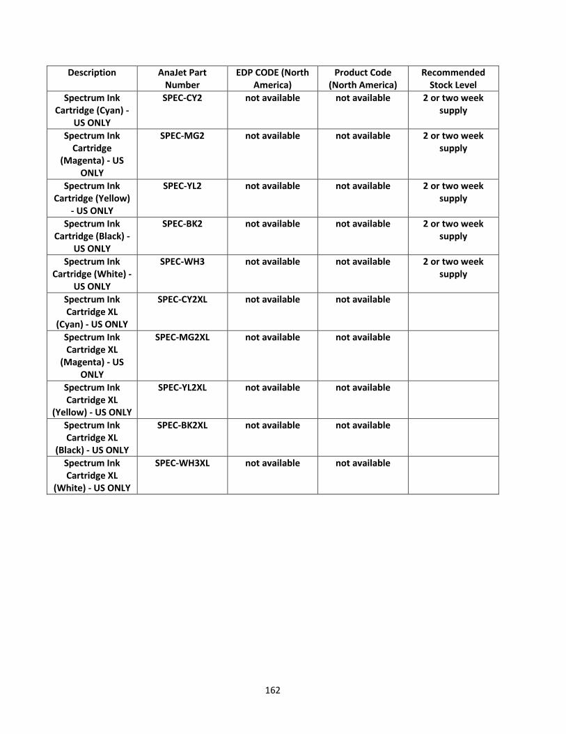
162
Description AnaJet Part Number
EDP CODE (North America)
Product Code (North America)
Recommended Stock Level
Spectrum Ink Cartridge (Cyan) -
US ONLY
SPEC-CY2 not available not available 2 or two week supply
Spectrum Ink Cartridge
(Magenta) - US ONLY
SPEC-MG2 not available not available 2 or two week supply
Spectrum Ink Cartridge (Yellow)
- US ONLY
SPEC-YL2 not available not available 2 or two week supply
Spectrum Ink Cartridge (Black) -
US ONLY
SPEC-BK2 not available not available 2 or two week supply
Spectrum Ink Cartridge (White) -
US ONLY
SPEC-WH3 not available not available 2 or two week supply
Spectrum Ink Cartridge XL
(Cyan) - US ONLY
SPEC-CY2XL not available not available
Spectrum Ink Cartridge XL
(Magenta) - US ONLY
SPEC-MG2XL not available not available
Spectrum Ink Cartridge XL
(Yellow) - US ONLY
SPEC-YL2XL not available not available
Spectrum Ink Cartridge XL
(Black) - US ONLY
SPEC-BK2XL not available not available
Spectrum Ink Cartridge XL
(White) - US ONLY
SPEC-WH3XL not available not available

163
Description AnaJet Part Number
EDP CODE (North America)
Product Code (North America)
Recommended Stock Level
Ricoh Garment Ink Type A (Cyan)
342008 J93000 2 or two week supply
Ricoh Garment Ink Type A (Magenta)
342009 J93001 2 or two week supply
Ricoh Garment Ink Type A (Yellow)
342010 J93002 2 or two week supply
Ricoh Garment Ink Type A (Black)
342011 J93003 2 or two week supply
Ricoh Garment Ink Type A XL (Cyan)
342013 J93005
Ricoh Garment Ink Type A XL (Magenta)
342014 J93006
Ricoh Garment Ink Type A XL (Yellow)
342015 J93007
Ricoh Garment Ink Type A XL (Black)
342016 J9308
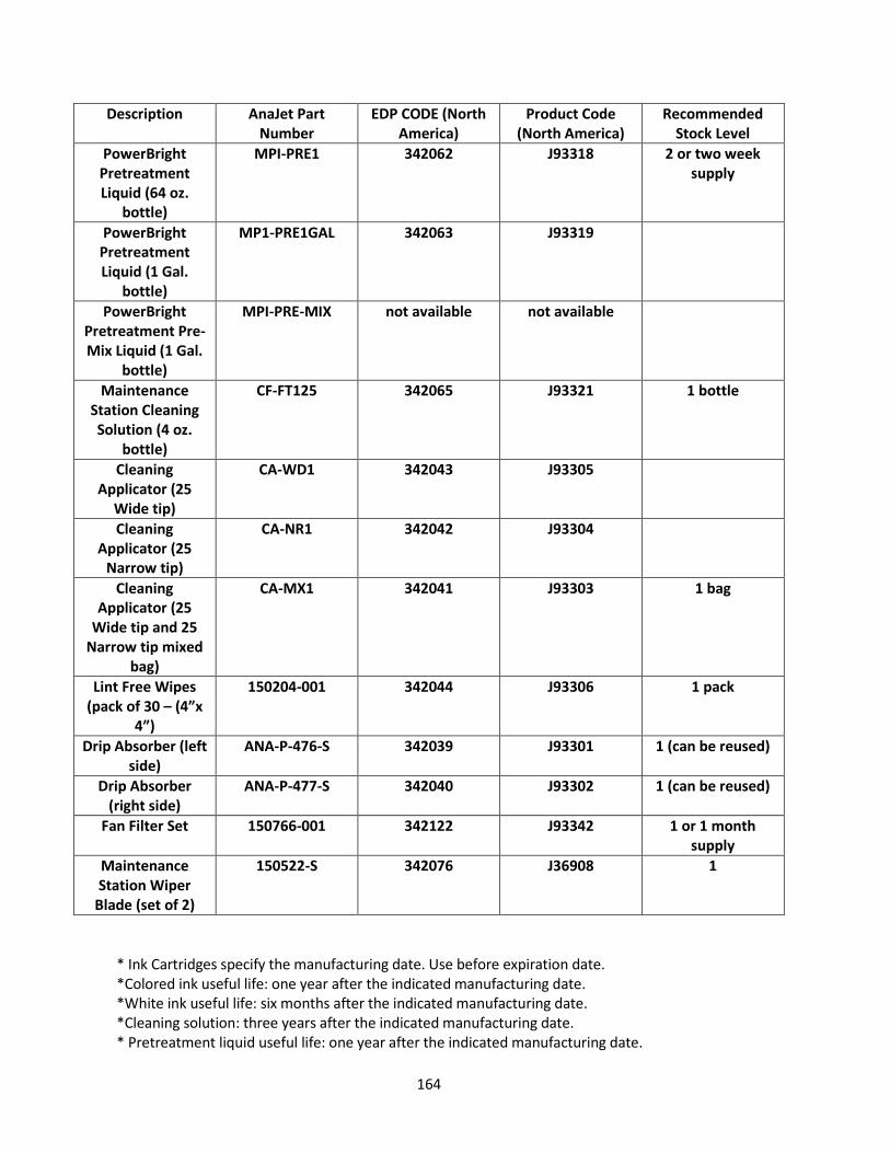
164
Description AnaJet Part Number
EDP CODE (North America)
Product Code (North America)
Recommended Stock Level
PowerBright Pretreatment Liquid (64 oz.
bottle)
MPI-PRE1 342062 J93318 2 or two week supply
PowerBright Pretreatment Liquid (1 Gal.
bottle)
MP1-PRE1GAL 342063 J93319
PowerBright Pretreatment Pre-Mix Liquid (1 Gal.
bottle)
MPI-PRE-MIX not available
not available
Maintenance Station Cleaning Solution (4 oz.
bottle)
CF-FT125 342065 J93321 1 bottle
Cleaning Applicator (25
Wide tip)
CA-WD1 342043 J93305
Cleaning Applicator (25
Narrow tip)
CA-NR1 342042 J93304
Cleaning Applicator (25
Wide tip and 25 Narrow tip mixed
bag)
CA-MX1 342041 J93303 1 bag
Lint Free Wipes (pack of 30 – (4”x
4”)
150204-001 342044 J93306 1 pack
Drip Absorber (left side)
ANA-P-476-S 342039 J93301 1 (can be reused)
Drip Absorber (right side)
ANA-P-477-S 342040 J93302 1 (can be reused)
Fan Filter Set 150766-001 342122 J93342 1 or 1 month supply
Maintenance Station Wiper
Blade (set of 2)
150522-S 342076 J36908 1
* Ink Cartridges specify the manufacturing date. Use before expiration date. *Colored ink useful life: one year after the indicated manufacturing date. *White ink useful life: six months after the indicated manufacturing date. *Cleaning solution: three years after the indicated manufacturing date. * Pretreatment liquid useful life: one year after the indicated manufacturing date.

165
RICOH Ri 3000 or RICOH Ri 6000 Recommended Non-Consumable Items
Description AnaJet Part Number
Remarks EDP CODE (North America)
Product Code (North America)
Print Table Platen 14” x 18”
ANA-P-457 Replacement Print Table
not available not available
Print Table Hoop 14.00” x 18.00”
150147-001 Replacement Print table hoop
342034 J36903
Youth Size Print Table 8.5” x 12.00”
150197-001 For Youth/Women’s
shirt printing
342036 J36905
Sleeve Print Table 150196-001 For Sleeve printing 342035 J36904
Small Print Adaptor
PKT1 For Small Pocket sized printing
Hat Platen 150511-001 For Mesh Cap printing
342037 J36906
Wagner – US ONLY WCS1 Hand Sprayer for applying
Pretreatment
342075 J36907

166
RICOH Ri 3000 or RICOH Ri 6000 Extended Media Consumables - US ONLY
Description AnaJet Part Number
Remarks EDP CODE (North America)
Product Code (North America)
Silver Foil (12 1/2" wide x 200 ft.) - US
ONLY MF-S
For Silver Foil application
342066 J93322
Gold Foil (12 1/2" wide x 200 ft.) - US
ONLY
MF-G For Gold Foil application
342067 J93323
Blue Foil (12 1/2" wide x 200 ft.) - US
ONLY
MF-B For Blue Foil application
342068 J93324
Green Foil (12 1/2" wide x 200
ft.) - US ONLY
MF-GR For Green Foil application
342069 J93325
Red Foil (12 1/2" wide x 200 ft.) - US
ONLY
MF-R For Red Foil application
342070 J93326
Ana EM Clear inkjet receptive -
US ONLY
EM-CC Clear Inkjet Coating for plastic, glass, and phone
not available not available
Ana EM matte inkjet receptive -
US ONLY
EM-WC Matte Inkjet Coating for wood,
metal
not available not available
Clear Jet UV protecting clear -
US ONLY
EM-UVC Protective UV Spray for printed
textiles
342071 J93327
ARTprint Canvas Pack - US ONLY
CANV-1319 25-sheet pack of precut 13" x 19"
pre-coated
342049 J93311
Texture Coat - US ONLY
TCSG-1 For use on printed materials only
not available not available
Texture Coat - US ONLY
TCMT-1 For use on printed materials
not available not available

167
2: Appendix 2 MAINTENANCE
CHECKLIST INITIAL WHEN MAINTENANCE IS
PERFORMED.
Date Nozzle Check
Head Clean
Shake White
Ink
Clean Maint. Stat.
Check Left &
Right Pan
Check Waste Ink
Cleaning Solution Charge
Other Misc.
Daily As Needed
Every 2-3 days
Weekly Weekly Monthly Every 3 Months
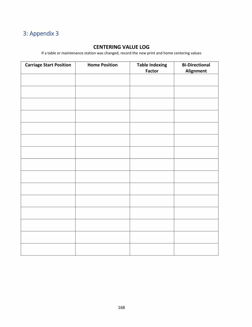
168
3: Appendix 3
CENTERING VALUE LOG If a table or maintenance station was changed, record the new print and home centering values
Carriage Start Position Home Position Table Indexing Factor
Bi-Directional Alignment

169
4: Appendix 4
Firmware Version History If control firmware version was changed or updated, record the version number
Version Number
Description Version Date
1.0

170


![RICOH Ri 1000 Operator Training...RICOH Ri 1000 Operator Training 05/11/2020 Version: [###] Classification: Internal Owner: [Insert name] 2 • Substrate • Environment • Heat Press](https://static.fdocuments.us/doc/165x107/6148b2de2918e2056c22db53/ricoh-ri-1000-operator-training-ricoh-ri-1000-operator-training-05112020-version.jpg)