Rhino 8-16 Installation Manual - FSK Electronics SA · FSK Wireless External PIR FSK Dual PIR IP65...
51
Transcript of Rhino 8-16 Installation Manual - FSK Electronics SA · FSK Wireless External PIR FSK Dual PIR IP65...


2 FSK-RAP816-V2015.04
Contents
1. System Overview .................................................... 4
System Configuration .............................................................. 4 Control Panel ........................................................................... 5 Remote Keypads ...................................................................... 5
Graphic LCD Remote Keypad .................................................... 5 LED Remote Keypad .................................................................. 5
Wireless Devices ...................................................................... 5 Indoor PIR ................................................................................. 5 Door Contact ............................................................................ 5 Bidirectional Gate Module ........................................................ 5 Relay Module - 4 Channel ......................................................... 5 Remote Control 6 Button .......................................................... 5 Third Party PIR Interface ........................................................... 5 FSK Wireless External PIR ......................................................... 5 Repeater ................................................................................... 5
FSK USB Serial Adapter (FUSA) ................................................ 5 Upload/Download Software .................................................... 5
2. Installation .............................................................. 6
Installation Sequence .............................................................. 6 Control Panel ........................................................................... 6
Mounting .................................................................................. 6 Wiring the Control Panel .......................................................... 6 Control Panel Layout ................................................................ 7 Connecting Devices to the Network ......................................... 9
Remote Keypads .................................................................... 10 PCB Layouts ............................................................................ 10
Wiring Detection Devices ...................................................... 10 Normally Closed ...................................................................... 10 Normally Open........................................................................ 10 Single EOL - N/C ...................................................................... 11 Double EOL ............................................................................. 11 Triple EOL................................................................................ 11
Loudspeaker Connections ..................................................... 12 External Sounder/Strobe Connections .................................. 12
0V ........................................................................................... 12 +12 .......................................................................................... 12 Bell (1)..................................................................................... 12 Strobe (2) ................................................................................ 12
Panel Outputs 1 - 4 ................................................................ 12 Configuring Wireless Devices ................................................ 13
On-board Wireless Interface ................................................... 13 RH-100 Wireless Door Contact ............................................... 13 RH-101 Wireless 3rd Party PIR Interface .................................. 13 RH-200 Wireless Indoor Passive ............................................. 14 RH-802 Bidirectional Gate module ......................................... 14 RH-806 Wireless Key Fob ........................................................ 15
Commissioning ...................................................................... 15
3. Programming the Control Panel ........................... 16
Introduction ........................................................................... 16 Easy Mode .............................................................................. 16 Expert Mode ........................................................................... 16
Exiting Engineer’s Program Mode ......................................... 16
Zone Configuration (Easy Mode) ............................................ 17 String Edit - Text Mode ............................................................ 17
Area Configuration (Easy Mode) ............................................ 17 Keypad Configuration (Easy Mode) ........................................ 18 Output Configuration (Easy Mode) ........................................ 18 User Configuration (Easy Mode) ............................................ 18 Expert Mode Menu Navigation .............................................. 19 1. Zone Programming ............................................................. 19
Zone Type ................................................................................ 19 Zone Wiring ............................................................................. 20 Zone Attributes ....................................................................... 20 Zone Areas .............................................................................. 21 Zone Bypass Options ............................................................... 21 Zone Chime ............................................................................. 21 Zone Soak Test ........................................................................ 21 Zone Text ................................................................................ 21 Zone Link ................................................................................. 22
2. Area Options....................................................................... 22 Area Timers ............................................................................. 22 Area Arming Modes ................................................................ 22 Area Configuration Options 1 .................................................. 22 Area Configuration Options 2 .................................................. 23 Area Configuration Options 3 .................................................. 23 Area Timer Control .................................................................. 23
3. System Configuration ......................................................... 24 System Timers ......................................................................... 24 System Counters ..................................................................... 25 Hardware - Volume Levels ...................................................... 25 Hardware - Output Monitoring ............................................... 25 Hardware - Monitoring ........................................................... 26 Speaker Sounds ....................................................................... 26 Configuration 1 ....................................................................... 26 Configuration 2 ....................................................................... 26 Control Timers ......................................................................... 27 Banner Text ............................................................................. 27 Remote Control Labels ............................................................ 27 Area Labels .............................................................................. 27 System Links ............................................................................ 27 Auto Arm and Auto Disarm ..................................................... 28
4. Keypad Configuration ......................................................... 28 Keypad Options 1 .................................................................... 28 Keypad Options 2 .................................................................... 28 Keypad Sounds ........................................................................ 28 Keypad Areas .......................................................................... 29
5. Expander Configuration ...................................................... 29 Expander Areas ....................................................................... 29 Expander Options .................................................................... 29 Expander Sounds ..................................................................... 29 Expander Outputs ................................................................... 30 Expander Output Attributes .................................................... 30 Expander Output Areas ........................................................... 30 Expander Output Link.............................................................. 30 Wireless Outputs ..................................................................... 30 Wireless Output Attributes ..................................................... 30 Wireless Output Areas ............................................................ 30 Wireless Output Link ............................................................... 30

FSK-RAP816-V2015.04 3
6. Panel Outputs and Devices ................................................ 31 Panel Output Type .................................................................. 31 Panel Output Attributes .......................................................... 31 Output Types .......................................................................... 31 00: Global ............................................................................... 31 Group 02: Control Timer ......................................................... 33 Group 03: Remote Control...................................................... 33 Group 04: Link Control ............................................................ 33 Group 10: Zone Count ............................................................ 34 Group 20: Zone Mimic ............................................................ 34 Group 30: Zone Alarm ............................................................ 34 Group 40: Zone Tamper .......................................................... 34 Group 50: Zone Masked ......................................................... 34 Group 60: Zone Fault .............................................................. 34 Group 70: Zone Bypassed ....................................................... 34 Group 80: User Access ............................................................ 34 Communication Port ............................................................... 34 IP Module ............................................................................... 35
7. Communicator (Optional) .................................................. 35 ARC 1-4: Telephone Number .................................................. 35 ARC 1-4: Account Number ...................................................... 35 ARC 1-4: Protocol .................................................................... 35 ARC 1-4: Protocol Options ...................................................... 35 ARC 1-4: Call Sequence/Attempts ........................................... 35 ARC 1-4: Reported Event Groups ............................................ 36 ARC 1-4: Cancel on Success..................................................... 36 ARC 1-4: Areas ........................................................................ 36 ARC 1-4: IP Address ................................................................ 36 ARC 1-4: IP Port Number ........................................................ 36 Options: Auto Test Call Period ................................................ 36 UDL Options ............................................................................ 37 UDL Password ......................................................................... 37 UDL IP Address........................................................................ 37 UDL IP Port.............................................................................. 37 UDL Account Number ............................................................. 37
8. System Users ..................................................................... 37 User Access Code .................................................................... 37 User Type ................................................................................ 37 User Locked By ....................................................................... 38 User Name .............................................................................. 38 User Link ................................................................................. 38 User Areas .............................................................................. 38
9. Utilities .............................................................................. 38 Time and Date ........................................................................ 38
User Menus ........................................................................... 38 Stay Arm 1 1 ....................................................................... 38
Stay Arm 2 2 ....................................................................... 38 Stay Arm 3 3 ....................................................................... 38 Away Arm 4 ........................................................................ 39 Show Chime Log 5............................................................... 39 Show Event Log 6 ................................................................ 39 Clear Notifications 7 ........................................................... 39 Change Code 8 .................................................................... 39 Start Walk Test 9................................................................. 39 Exit Menu 0 ......................................................................... 39
4. SMS Commands .................................................... 40
SMS Introduction ................................................................... 40 SMS Control Function ............................................................. 40
5. MiRhino App ......................................................... 40
6. Log Events ............................................................. 41
7. Status LED Indications .......................................... 43
8. Fault & Status Messages ...................................... 43
9. Default Zones Configuration ................................ 44
10. Status LED Indications .......................................... 46
11. Fault & Status Messages ...................................... 47
12. Specifications ........................................................ 48
Rhino 816 Control Panel ......................................................... 48 Electrical .................................................................................. 48 Environmental ......................................................................... 48 Physical ................................................................................... 48
LED Remote Keypad ............................................................... 48 Electrical .................................................................................. 48 Environmental ......................................................................... 48 Physical ................................................................................... 48
LCD Remote Keypad ............................................................... 48 Electrical .................................................................................. 48 Environmental ......................................................................... 48 Physical ................................................................................... 48
Standards ............................................................................... 49 Safety ...................................................................................... 49 EMC ......................................................................................... 49 Security ................................................................................... 49
Warranty ................................................................................ 49

4 FSK-RAP816-V2015.04
1. System Overview
System Configuration

FSK-RAP816-V2015.04 5
Control Panel The Rhino 816 control panel is an advanced intruder alarm system with 8 on-board zones and optional on-board wireless transceiver to allow support for wireless devices. The system is ideally suited to domestic and small commercial installations.
The system can be further enhanced by using the Rhino GSM module which provides both remote signalling and UDL connectivity.
A choice of either LCD or LED remote keypads is available. Other features include:
f 8 programmable on-board wired zone inputs
f Another 8 programmable expander wired zone inputs
f Or 16 Wireless zone inputs
f 4 programmable wired outputs (1 Amp rated)
f 16 programmable wireless outputs
f On-board wireless transceiver
f Local or remote upload/download
f 500 event log
f Advanced system diagnostics
f 1.2 Amp power supply
f 2 serial ports (RhinoBus and USB-Link)
f Flash upgradable
Remote Keypads The Rhino 816 will accept up to a maximum of 4 remote keypads. All remote keypads require a 4-wire connection to the control panel using standard alarm cable. The following remote keypad models are available:
Graphic LCD Remote Keypad The Graphic LCD keypad features a 128 x 64 pixel display for showing all zone status and system fault messages. A set of dedicated system status LEDs for Power, Status and Trouble are also provided. Other features include:
f 4-wire connection using standard alarm cable
f Internal sounder
f Blue Backlit keyboard with adjustable brightness
f Full system programming and diagnostics
LED Remote Keypad The LED keypad features 16 zone status LEDs for zone status and 7 dedicated system status LEDs for AC, Ready, Armed, Bypass, Chime, Alarm and Fault. Other features include:
f 4-wire connection using standard alarm cable
f Internal sounder
f Backlit keyboard
f Full system operation (arm, disarm etc.)
The system can only be programmed using a Graphic LCD keypad or the via the Rhino UDL software.
Wireless Devices The following wireless devices are available:
Indoor PIR An indoor 12 metre passive infra-red detector.
Door Contact A magnetic door contact sensor with an additional zone input for monitoring other normally closed detectors.
Bidirectional Gate Module A small module with a single zone input and one output.
Relay Module - 4 Channel A 4 channel relay module.
Remote Control 6 Button Key fob for remotely arming, disarming and switching outputs on and off.
Third Party PIR Interface A module that interfaces third party PIR’s e.g. Takex.
FSK Wireless External PIR FSK Dual PIR IP65 Small Form Factor External PIR.
Repeater A module used to extend the range of wireless devices.
FSK USB Serial Adapter (FUSA) The FUSA provides USB connectivity between the Rhino 816 and the host computer. It is required when a direct connection is required between the Rhino UDL software package and the control panel.
Upload/Download Software Rhino UDL is a Windows® based software package that can be used to remotely or locally program and diagnose the Rhino range of security systems. Features include:
f Simple intuitive user interface
f Local or remote via modem and IP
f System remote control
f Advanced system diagnostics
f Multi language support

6 FSK-RAP816-V2015.04
2. Installation
Installation Sequence Before attempting to install the alarm system, read this section. Once you have an overall understanding of the installation sequence, carefully work through each step.
1. Design the Layout Make a rough sketch of the premises to get an idea of where all alarm detection devices, keypads and other modules are to be located.
2. Mounting the Control Panel The control panel must be mounted within the protected area close to an AC power source.
You must complete all wiring before connecting the battery, or applying AC to the panel.
3. Install the Remote Keypads Mount the remote keypads at locations that are easily accessible during entry and exit from the protected area. Connect the remote keypads to the control panel.
4. Zone Wiring Install detection devices and connect to control panel or expander.
5. Other Wiring Complete all other wiring including external/internal sounders and telephone line connections.
6. Apply Power to the Control Panel Once steps 1 to 5 are completed, apply power to the control panel. First, connect the red battery lead to the positive terminal and the black lead to negative. Then, connect the AC.
7. Program the System If available use the Rhino UDL software package to program the system, if this is not available program this system in accordance with the procedures in Section 3.
8. Testing the System Test the system thoroughly to ensure that all features and functions are operating as required.
Control Panel
Mounting Mount the control panel on a flat, plumb wall using at least three appropriate screws. The rear casing has been designed with a several key-hole slots so that mounting is possible without removing the Printed Circuit Board (PCB).
It is essential to ensure that none of the fixing slots or cable entries are accessible after fixing.
Wiring the Control Panel
WARNING: ELECTRICITY CAN KILL
BEFORE connecting the control panel ALWAYS disconnect the supply at the consumer unit.
If in ANY doubt consult a qualified electrician.
ONLY connect the mains supply from the transformer to the mains terminal block, NEVER connect the mains supply directly to the PCB.
The system installation MUST be carried out in accordance with the national safety standards, for example EN 60950: 1992.
ALWAYS refer to National Wiring Regulations when conducting installation.
An appropriate and readily accessible disconnection device (e.g. an unswitched fused spur) MUST be provided as part of the installation.
The disconnection device must NOT be fitted in a flexible cord.
Where identification of the neutral in the mains supply is NOT possible, a two-pole disconnection device MUST be used.
The building mains supply MUST incorporate appropriate short-circuit backup protection (e.g. a fuse or circuit breaker) of High Breaking Capacity (HBC, at least 1500A).
Use mains cable of adequate carrying capacity for the rated current (i.e. at least 0.75mm2).
The system installation MUST be carried out in accordance with the expected norms in the industry, for example, SAIDSA By-law 5 and By-law 25 (amongst others).

FSK-RAP816-V2015.04 7
Control Panel Layout
1. Main Printed Circuit Board (PCB) The main PCB that provides the terminals connection to remote keypads and detection devices, see PCB Layout on next page for full details.
2. Standby Battery The system housing will accept a 12V 7Ah battery to provide continued operation in the event of an AC mains failure. Connect the red battery lead to the positive terminal of the battery and then connect the black battery lead to the negative terminal.
3. GSM Module An optional Rhino GSM Module can be plugged onto the main PCB.
4. GSM Antenna Screw in GSM antenna for optional Rhino GSM Module.
5. Wireless Antenna Screw in wireless antenna for on-board wireless transceiver.

FSK-RAP816-V2015.04 8
PCB Layout
1. AC Input The two wires from the transformer are connected to these terminals and supply power the system.
2. Network Connections The network terminals provide connections to the remote keypads and zone expanders. The RED and BLK terminals provide power whilst the GRN and YEL terminals are the data signals.
3. Zone Inputs 1 to 8 Detection devices such as movement sensors, vibration and door contacts are connected to the zone input terminals. There are several ways in which to wire a detection device (see page 10). Each zone is fully programmable, see page 19 for information on programming zones.
4. Aux Tamper Input This terminal provides tamper detection for auxiliary devices. If it is not required link it to 0V.
5. Auxiliary 12V These terminals provide auxiliary power for the external sounder and detection devices that require 12V power, e.g., moment sensors. The auxiliary output is protected by an auto resetting fuse (PTC) rated at 1.1 Amp).
6. Panel Outputs 1 to 4 These are fully programmable high current (1 Amp), switched negative supervised outputs. Panel outputs 1 and 2 default to bell and strobe operation, but can be programmed for other functions if required, see page 31 for programming details. Each output can also be programmed for supervision monitoring, see page 25.
Panel output 4 defaults as speaker driver and is used for driving 16Ω extension loudspeakers (see page 12). If a loudspeaker driver is not required it can be used as a standard output.
7. RhinoBus Port The Rhino bus terminals provide connection to Rhino communication modules.
8. COM Port 1 & 2 COM 1 is provided for local downloading and for third party devices. COM2 is in parallel with the RhinoBus Port (7) and provides a different method of connecting compatible modules.
9. Power/Status LED On steady when either AC or standby battery is present. Flashes when the communicator is sending data.
10. Lid Tamper Connector This connector can be used to connect a lid tamper switch to provide protection for when the enclosure cover is opened.
11. Antenna Screw Connector This connector provides a screw in connection for the on-board wireless transceiver antenna.
12. Battery Connections A 12V rechargeable battery must be connected to these two terminals in order to provide continuous system operation in the event of mains failure. The battery output is protected by an auto resetting fuse (PTC) rated at 1.6 Amp.

FSK-RAP816-V2015.04 9
Connecting Devices to the Network Before connecting devices to the control panel network, isolate ALL power from the control panel (AC Mains & Battery). Do not continue if there is still power present on the control panel.
Connecting devices with power still present on the control panel may damage the device or control panel and invalidate any warranty.
Remote keypads are all connected to the network terminals located at the bottom left hand corner of the control panel and may be connected serially (daisy chain), in parallel (star) or any combination of the two.
Network Connections The network is made up of four terminals incorporating power and data. To ensure correct operation, all four terminals on the device must be connected to the corresponding terminals on the control panel, or previous device. The table below shows each terminal and its description:
+ RED +12V Supply
- BLK 0V Supply
R GRN Data Return
D YEL Data I/O
Cable Type and Distances For improved immunity to electrical noise, the use of screened 4 core cable is recommended. The screen should be twisted together and wired into the (–) terminal at the control panel only.
The maximum recommended distance for devices when using standard 7/0.2 alarm cable is:
f 250m for each branch when using the star (parallel) configuration
f When using a daisy chain (series) configuration the maximum distance will depend on the number of devices connected on the chain. The more devices that are connected, the shorter the distance to the last device (this is due to voltage drop in the cable)
Whichever method of wiring configuration is used, ensure that the voltage between the ‘+’ and ‘–’ terminals at each device is no lower than 10.0V when the system is running on the standby battery.
Overcoming Voltage Drop There are several ways to overcome voltage drop:
f Use thicker lower resistance cable. Standard 7/0.2 alarm cable has a resistance of 8Ω per 100m
f Double up on the power connections – this will require using a 6 or 8-core cable rather than a 4-core cable
f Install a power supply to power the device locally, remember to common the two negative connections
Installing a Power Supply When a power supply is installed, the 0V connections on the power supply must be connected through to 0V on the control panel and the +12V connection between the control panel and the device must be disconnected (see figure below).
The maximum tested network distance is 400m.

10 FSK-RAP816-V2015.04
Remote Keypads
PCB Layouts
LED Remote Keypad
Graphic LCD Remote Keypad
1. Network Connections The remote keypad is connected to the network terminals located at the bottom left hand side of the PCB.
2. Address Selection (Led keypad only) Each remote keypad must be assigned a different address using the Address selector. Move the jumper to the required position 1, 2, 3 or 4. To assign a keypad number to a graphic LCD remote keypad, please refer to the graphic LCD keypad manual.
3. Piezo Sounder The piezo sounder generates low level alarm, key press, and warning tones. Each type of tone can be enabled or disabled for each remote keypad, please refer to page 28 for further details.
Wiring Detection Devices The Rhino 816 provides 8 zones for connecting detection devices such as movement sensors and magnetic door contacts. Each zone is fully programmable to allow for maximum flexibility (see page 19 for Zone Programming details). The program options for a zone will also determine how the zone may be wired. The following wiring options are available:
Normally Closed This wiring configuration should be used when connecting detection devices that only have a normally closed alarm output. Connect the detector as shown below and ensure that the zone is programmed for “Normally Closed” operation, see page 20.
Normally Open This wiring configuration should be used when connecting detection devices that only have a normally open alarm output. Connect the detector as shown below and ensure that the zone is programmed for “Normally Open” operation, see page 20.

FSK-RAP816-V2015.04 11
Single EOL - N/C This wiring configuration should be used when connecting detection devices that only have a normally closed alarm output. Connect the detector as shown below and ensure that the zone is programmed for “Single EOL – N/C” operation, see page 20.
Double EOL This wiring configuration should be used when connecting detection devices that have a normally closed alarm and tamper output. Connect the detector as shown below and ensure that the zone is programmed for “Double EOL” operation, see page 20.
Triple EOL This wiring configuration should be used when connecting detection devices that support triple EOL configuration, this will allow the system to monitor alarm, tamper fault and mask. Connect the detector as shown below and ensure that the zone is programmed for “Triple EOL” operation, see page 20.

12 FSK-RAP816-V2015.04
Loudspeaker Connections The Rhino 816 has a loudspeaker output capable of driving one 16Ω or two 8Ω wired in series as shown below:
The volume level can be programmed, please refer to page 25 for details. The loudspeaker can also be tested, please refer to page 25 for further details.
External Sounder/Strobe Connections The following connections are available for connection to an external sounder/strobe unit:
0V 0V supply. Connect to the 0V (-) supply on the external sounder/strobe unit.
+12 Positive 12V supply, which is protected by an auto resetting fuse (PTC) rated at 1.1A. Connect to the +12V (+) supply on the external sounder/strobe unit.
Bell (1) Panel output 1 is pre-configured for Bell operation, i.e. it switches to 0V when active. Connect this terminal to the bell trigger input on the external sounder/strobe unit.
Strobe (2) Panel output 2 is pre-configured for Strobe operation, i.e., it switches to 0V when active. Connect this terminal to the strobe input on the external sounder/strobe unit.
Panel Outputs 1 - 4 The control panel has four programmable outputs, which can be used to drive auxiliary devices such as LEDs, sounders or relays etc. (see page 31 for details on programming outputs). Each panel output is rated at 1 Amp and switches to 0V when active. The figure bellow shows some wiring examples:

FSK-RAP816-V2015.04 13
Configuring Wireless Devices This section covers the setting up and installation of wireless devices.
On-board Wireless Interface The Rhino 816 has a wireless transceiver that is integrated onto the main PCB. It allows a support for various wireless devices.
RH-100 Wireless Door Contact The RH-100 is a professional state-of-the-art wireless door contact sensor. It has two zones, one on the magnetic (reed) switch and one on the zone input terminals.
The RH-100 must be allocated to one of the available zones (1-8). However, if the device is allocated to an on-board wired zone (1-6), the wired zone input will be disabled.
The figure below show the layout of the RH-100 Wireless Door Contact:
1. Battery Location The wireless door contact is powered by a CR2 3V Li-ion battery, which must be fitted correctly. Please wait 60 seconds after battery installation for the device to initialise.
2. Tamper Switch The lid tamper detection switch, this switch is also used when learning the device onto the system.
3. Activity LED The activity LED illuminates when the device is transmitting a wireless signal.
4. Zone Input Terminals The wireless door contact has two detection inputs. The first is the magnetic reed switch that is activated by the magnet. The second requires a voltage free normally closed contact and is wired into these terminals. Both inputs report back to the same zone on the control panel. If the zone input is unused it must be linked out.
5. Magnetic Reed Switch The magnetic reed switch detects the presence of the magnet fitted to the door.
The Magnetic Reed switch is always in operation. If you only require the use of the Zone Input Terminals, the magnet must be held close to the reed switch at all times.
6. Antenna The wireless antenna used for transmitting the wireless signal.
RH-101 Wireless 3rd Party PIR Interface The RH-101 is a professional state-of-the-art wireless module that is specifically engineered to be sub-equipped into other brands of PIR sensors. It features an Alarm Normally Closed contact as well as a Tamper Normally Closed contact. The tamper contact is also wired in series with the internal case tamper contact on the PCB.
The RH-101 must be allocated to one of the available zones (1-16). However, if the device is allocated to an on-board wired zone (1-8), the wired zone input will be disabled.
The figure below show the layout of the RH-101 Wireless 3rd Party PIR Interface:
1. Battery Location The wireless door contact is powered by a CR2 3V Li-ion battery, which must be fitted correctly. Please wait 60 seconds after battery installation for the device to initialise.
2. Tamper Switch The lid tamper detection switch, this switch is also used when learning the device onto the system.
3. Activity LED The activity LED illuminates when the device is transmitting a wireless signal.
4. Alarm Input Terminals The normally closed alarm output from the 3rd party detector is connected to these terminals.
5. Tamper Input Terminals The normally closed tamper output from the 3rd party detector is connected to these terminals.
6. Antenna The wireless antenna used for transmitting the wireless signal.

14 FSK-RAP816-V2015.04
RH-200 Wireless Indoor Passive The Rh-200 is a professional state-of-the-art motion sensor engineered with the world's best components and materials, starting with a HighView™ lens and a top-quality infrared detector. Next, a patented modern DSP ASIC directly converts the infrared detector signal into digital form, for best reliability and stability. Finally, the signal is evaluated by HighBar™ processing, for "best-in-class" false alarm rejection with excellent intruder detection.
The RH-200 must be allocated to one of the available zones (1-8). However, if the device is allocated to an on-board wired zone (1-6), the wired zone input will be disabled.
The figure below show the layout of the RH-200 Wireless Indoor Passive:
1. Battery Location The wireless indoor passive is powered by a CR123 3V Li-ion battery, which must be fitted correctly. Please wait 60 seconds after battery installation for the device to initialise.
2. Tamper Switch The lid tamper detection switch, this switch is also used when learning the device onto the system.
3. Activity LED The activity LED illuminates when movement is detected and when the device is transmitting a wireless signal.
RH-802 Bidirectional Gate module The RH-802 (Single Channel IO Module) is a professional state-of-the-art wireless 1 Zone Input & Output module. It has specifically been developed for applications like controlling Gate Motors, Garage Door Openers, Sprinkler Systems, etc. Due to the fact that it has both an output and an input function, the output can be used to control the external equipment and the input zone can be used to provide physical feedback of the external equipment actual status. For example the output can be used to control a gate motor and the input zone can be used to show whether the gate is closed or open via a wired magnetic reed switch.
The RH-802 must be allocated to one of the available zones (1-8). However, if the device is allocated to an on-board wired zone (1-6), the wired zone input will be disabled.
The output is not available when the RH-802 is used with the Rhino 816 but can be programmed to directly connect to other devices like FOB or another Bidirectional Gate Module
The figure below show the layout of the RH-802 Bidirectional Gate Module:
1. Supply Terminals The RH-802 must be powered from either a 12V or 24V DC supply.
2. Relay Output A set of voltage free change over contacts. COM - Common; NC - Normally Closed; NO - Normally Open.
3. Input These terminals provide 2 methods for connecting external equipment:
4. Ground The ground terminal is connected to - supply terminal for a common 0V reference.
5. Learn Button This button is used when learning the device onto the system.
6. Relay Control Indicator This LED indicates if the Relay Control Message has been received.
7. Wireless Activity Indicator This LED indicates when a radio packet is received or transmitted.

FSK-RAP816-V2015.04 15
RH-806 Wireless Key Fob Each user maybe assigned a wireless key fob to allow remote control of the system. The figure below shows the layout of the key fob:
Standard Remote Control
Beep Remote Control
1. Panic Alarm This button activates the panic alarm.
2. Away Arm This button Away Arms the areas allocated to the user
3. Disarm This button disarms the areas allocated to the user.
4. Stay Arm This button stay arms the areas allocated to the user.
5. Remote Control 1 This button toggles on and off outputs that are programmed as “Remote Control 1.
6. Remote Control 2 This button toggles on and off outputs that are programmed as “Remote Control 2.
7. Activity LED The activity LED illuminates when the key fob is transmitting a wireless signal.
Commissioning Once ALL connections have been made to the control panel and power is ready to be applied, you should read this section before continuing.
The control panel leaves the factory programmed with default settings and when the system is powered up for the first time the default settings are in use. If the factory defaults need to be reloaded in future, press “CLEAR, 9 then ENTER” on the graphic LCD keypad within 10 seconds after powering up the panel.
f Connect the black battery lead to the negative (–) terminal of the standby battery and the red battery lead to the positive (+) terminal of the standby battery. The green power LED on the main PCB will light.
f If the system enters into an alarm condition, enter the default master user code 1234. The alarm tone will then stop.
f To access the Engineer Programming Menu, enter the default engineer code 789000. The remote keypads will show:
f Program the system as described in the next section (Programming the Control Panel).
f Carry out a walk test as described on page 39. Remember that some powered detectors (e.g. PIRs and combined technology detectors) take several minutes to warm up before they become operational.
f Replace the lid and secure with the lid screw supplied - do not over-tighten.
f Press Clear to select “Exit Menu” then Enter to exit the engineer’s program mode.
Installation is now complete and the system is ready for use. Please ensure the system users are provided with adequate training on operating the alarm system.
16 FSK-RAP816-V2015.04
3. Programming the Control Panel
Introduction This section covers the system programming and it is important that all engineers read this section carefully so as to familiarise themselves with the many features and functions of the control panel. To access the programming menu, enter the factory default engineer code 789000. If a mistake is made whilst entering the code, simply re-enter the code correctly.
The system configuration and programming is broken down into two modes:
Easy Mode This mode allows access to the most common programmable features. The following easy modes are available:
1: Zone Configuration
2: Area Configuration
3: Keypads
4: Outputs
5: Users
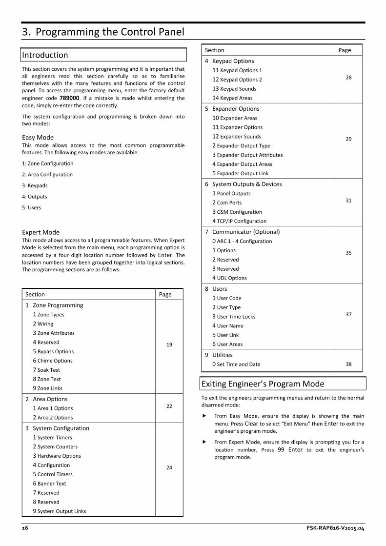
Expert Mode This mode allows access to all programmable features. When Expert Mode is selected from the main menu, each programming option is accessed by a four digit location number followed by Enter. The location numbers have been grouped together into logical sections. The programming sections are as follows:
Section Page
1 Zone Programming 1 Zone Types 2 Wiring 3 Zone Attributes 4 Reserved 5 Bypass Options 6 Chime Options 7 Soak Test 8 Zone Text 9 Zone Links
19
2 Area Options 1 Area 1 Options 2 Area 2 Options
22
3 System Configuration 1 System Timers 2 System Counters 3 Hardware Options 4 Configuration 5 Control Timers 6 Banner Text 7 Reserved 8 Reserved 9 System Output Links
24
Section Page
4 Keypad Options 11 Keypad Options 1 12 Keypad Options 2 13 Keypad Sounds 14 Keypad Areas
28
5 Expander Options 10 Expander Areas 11 Expander Options 12 Expander Sounds 2 Expander Output Type 3 Expander Output Attributes 4 Expander Output Areas 5 Expander Output Link
29
6 System Outputs & Devices 1 Panel Outputs 2 Com Ports 3 GSM Configuration 4 TCP/IP Configuration
31
7 Communicator (Optional) 0 ARC 1 - 4 Configuration 1 Options 2 Reserved 3 Reserved 4 UDL Options
35
8 Users 1 User Code 2 User Type 3 User Time Locks 4 User Name 5 User Link 6 User Areas
37
9 Utilities 0 Set Time and Date
38
Exiting Engineer’s Program Mode To exit the engineers programming menus and return to the normal disarmed mode:
f From Easy Mode, ensure the display is showing the main menu. Press Clear to select “Exit Menu” then Enter to exit the engineer’s program mode.
f From Expert Mode, ensure the display is prompting you for a location number, Press 99 Enter to exit the engineer’s program mode.

FSK-RAP816-V2015.04 17
Zone Configuration (Easy Mode) The flowchart below shows how to navigate the Zone Configuration menu. For full description of each option please refer to page 19.
Bypass Options
Key
Bypass Mode
Description
1 S1 Zone bypassed on Stay 1 mode
2 S2 Zone bypassed on Stay 2 mode
3 S3 Zone bypassed on Stay 3 mode
4 M Zone bypassed manually
5 A Zone auto - bypassed
6 K Zone Key switch bypassed
String Edit - Text Mode This type of data entry is used for entering text such as user names and zone text. The text is entered in the same way as entering text on a mobile telephone. Each key is mapped to one or more letters. Pressing a key will select the first letter, pressing it again will select the next etc. The table below shows the keys to use and the characters that are assigned to them:
Key Characters 1 1
2 A B C 2 a b C
3 D E F 3 d e F
4 G H I 4 g h I
5 J K L 5 j k L
6 M N O 6 m n O
7 P Q R S 7 p Q r s
8 T U V 8 t u V
9 W X Y Z 9 w X y z
0 _ 0 . - * # @
i Next character
Area Configuration (Easy Mode) The flowchart below shows how to navigate the Area Configuration menu. For full description of each option please refer to page 22.

18 FSK-RAP816-V2015.04
Keypad Configuration (Easy Mode) The flowchart below shows how to navigate the Keypad Configuration menu. For full description of each option please refer to page 28.
Output Configuration (Easy Mode) The flowchart below shows how to navigate the Output Configuration menu. For full description of each option please refer to page 31.
User Configuration (Easy Mode) The flowchart below shows how to navigate the User Configuration menu. For full description of each option please refer to page 37.

FSK-RAP816-V2015.04 19
Expert Mode Menu Navigation Expert Mode allows access to all programming options and features.
Each programming location is accessed by entering its four digit location number followed by Enter. If you don’t know the exact location you can enter less than four digits and the panel will take you to the first location that starts with numbers you have entered. For example if you enter 12 the panel will take you to location 1201 – Zone 01 Wiring Type.
When the panel gets defaulted, configuration settings shown in bold take effect.
WHEN THE PANEL GETS DEFAULTED, CONFIGURATION SETTINGS SHOWN IN BOLD THROUGHOUT THE MANUAL TAKE EFFECT.
1. Zone Programming This section covers programming of the detection zones, each zone must be programmed a zone type, wiring type and attributes.
DEFAULT CONFIGURATION SETTINGS FOR ZONES WHEN THE PANEL IS DEFAULTED BY PRESSING “CLEAR, 9, ENTER” ARE SHOWN ON PAGE 44.
Zone Type Each zone must be programmed to the correct type in order for the correct response.
Locations: 1101 to 1116
Zone 01 to 16: Zone Type.
Entry Mode: Enter 4 digit location followed by Enter, then key in 2 digit zone type from list below or press i to scroll through list. When finished press Enter to accept or Clear to cancel.
00 Not Used Use this zone type for unused zones, as zones programmed as “Not Used” are not be monitored by the system.
01 Delay 1/Final Exit 1 Use this zone type for the main entry/exit detector, normally a magnetic contact on the front door. The zone can be activated
during the exit mode without causing a fault. If the system is armed, activation of the zone will start the Entry 1 Delay timer for the relevant arm mode.
02 Delay 2/Final Exit 2 Use this zone type for an alternative entry/exit detector. The zone can be activated during the exit mode without causing a fault. If the system is armed, activation of the zone will start the Entry 2 Delay timer for the relevant arm mode.
03 Walk Through Use this zone type for detection devices along the entry/exit route. This zone type will allow the user to walk past the detector without causing a fault during the exit mode or an Intruder alarm during the entry mode. However, if activated at any other time the zone will cause an immediate intruder alarm. This zone type will also start the entry mode when the system is stay armed.
04 Intruder Use this zone type for detection devices such as PIR’s, vibration detectors, magnetic door contacts etc. This zone type generates an intruder alarm if activated when the system is armed.
05 Perimeter Use this zone type for detection devices such as external PIR’s, IR beams. This zone type generates an intruder alarm if activated when the system is armed.
06 Fire Use this zone type for smoke and heat detectors. This zone type generates a distinctive fire alarm if activated at any time.
07 PA Silent Use this zone type for panic buttons. This zone type generates a silent panic alarm if it is activated at any time.
08 PA Audible Use this zone type for panic buttons. This zone type generates an audible panic alarm if it is activated at any time.
09 Medical Use this zone type for medical alarms. This zone type generates a medical alarm if it is activated at any time.
10 24 Hour Use this zone type for detectors that require 24 hour monitoring. This zone type generates an intruder alarm if it is activated when the system is armed. If activated during the disarmed state an internal alarm is generated.
11 Tamper Use this zone type for tamper protection. This zone type generates a tamper alarm if it is activated when the system is armed. If activated during the disarmed state an internal alarm is generated.
12 Exit Terminator Use this zone type for external push to set buttons. This zone type terminates the exit delay when activated during exit mode. The arming mode must be configured for “Exit Terminator” for this zone type to function.
13 Away Arm Key Use this zone type for a key switch or lock that has switch contacts. This zone type will away arm the assigned areas when active and disarm the assigned areas when healthy. If a “momentary” operation is required then the “Momentary Keyswitch” attribute can be assigned, see page 21.
14 Stay 1 Arm Key Use this zone type for a key switch or door lock that has switch contacts. This zone type will stay arm (1) the assigned areas when active and disarm the assigned areas when healthy. If a

20 FSK-RAP816-V2015.04
“momentary” operation is required then the “Momentary Keyswitch” attribute can be assigned, see page 21.
15 Stay 2 Arm Key This zone type operates as type 14, but performs a stay arm 2.
16 Stay 3 Arm Key This zone type operates as type 14, but performs a stay arm 3.
17 Bypass Key Use this zone type for a key switch or door lock that has switch contacts. This zone type will bypass all zones with the keyswitch bypass attribute when active and reinstate them when healthy. If a “momentary” operation is required then the “Momentary Keyswitch” attribute can be assigned, see page 21.
18 Security Key Use this zone type for a key switch. This zone type will disable all remote keypads from disarming the panel when active and reinstate them when healthy. If a “momentary” operation is required then the “Momentary Keyswitch” attribute can be assigned, see page 21. If you want to change a zone from being a security key to another zone type, make sure you enable the remote keypads first.
19 Auxiliary Use this zone type for auxiliary devices, which do not require an audible alarm response. This zone type generates a silent alarm if activated at any time.
20 Warning Use this zone type for monitoring devices that require a warning indication. This zone type generates a warning (alarm tone on remote keypad and zone indication) if the zone remains active for longer than the warning delay time, see page 25 for details.
21 Log/Monitor Use this zone type for monitoring devices that require an event log entry. This zone type generates a log entry if activated at any time.
22 Trouble/Fault Use this zone type for monitoring fault outputs on devices such as remote power supplies. This zone type generates a fault condition if it is activated at any time.
23 Counter Use this zone type for counting the number of activations from a detector. For example it could be used to count the number of times a door is opened for a shop premises. This zone type does not generate an alarm; it is only used for counting purposes.
Zone Wiring Each zone must be programmed to the correct wiring type in order for the correct response.
Locations: 1201 to 1216
Zone 01 to 16: Zone Wiring.
Entry Mode: Enter 4 digit location followed by Enter, then key in 1 digit wiring type from list below or press i to scroll through list. When finished press Enter to accept or Clear to cancel.
0 Normally Closed Use this wiring type for normally closed detection devices.
1 Normally Open Use this wiring type for normally open detection devices.
2 Single EOL - N/C Use this wiring type for normally closed detection devices.
3 Double EOL Use this wiring type for detection devices that require both alarm and tamper monitoring.
4 Triple EOL Use this wiring type for detection devices that require alarm, tamper, fault and anti-mask monitoring.
5 User Double EOL Do not use, reserved for future use.
6 User Triple EOL Do not use, reserved for future use.
7 Wireless Use this wiring type for wireless devices, when this wiring type is selected the system will enter “Learn Mode” for 60 seconds and the wireless device must be activated (Tamper). To remove a device, simply program the wiring type as “Normally closed”. See page 13 for more information on wireless devices.
Zone Attributes Each zone can have one or more optional attributes programmed to further alter its functionality.
Locations: 1301 to 1316
Zone 01 to 16: Zone Attributes.
Entry Mode: Enter 4 digit location followed by Enter, then use keys 1 to 8 to toggle options from the list below on or off. When finished press Enter to accept or Clear to cancel.
1 Double Knock On: When a zone is enabled for Double Knock it will only cause an
alarm when: (a) The zone remains active for the duration of the “Double Knock Delay”. (b) The zone is violated twice within the “Double Knock Delay”. (c) If any two zones with the “Double Knock” attribute are activated during the “Double Knock Time Window”.
Off: The zone functions as normal.
2 Enable Comms On: The communicator will report the alarm status to the
monitoring station when the zone causes an alarm. Off: The alarm status is not transmitted.
3 Reset On: Zones with this attribute will not be monitored during the
detector reset period. The detector reset occurs when the exit mode is started or when the user resets the system after an alarm. Detection devices such as smoke detectors that are powered from an output programmed as “Detector Reset” should have this attribute switched on.
Off: The zone functions as normal.
4 Fast Response On: Zones with this attribute respond at the response rate
determined by the “Zone Response Timer”. Off: The zone functions as normal.
5 Auto Rearm On: Zones with this attribute will only re-arm at the end of the bell
duration providing that the “Auto Re-Arm Counter” limit has not been reached. Once this limit has been reached, the zone will lock out and not cause any further Intruder alarms.
Off: The zone will always re-arm.

FSK-RAP816-V2015.04 21
6 Remote Detector Test On: Zones with this attribute are monitored for specific activity
during the remote detector test. The detector must be connected to the control panel using triple EOL wiring and the detector remote test input must be connected to a panel output programmed as “Remote Detector Test”.
Off: The zone functions as normal.
7 Momentary Keyswitch On: If the zone type is a keyswitch type, the operation mode is
changed to momentary. Off: If the zone type is a keyswitch type, the operation remains as
latching mode.
8 Record Activity On: Zone activity will be recorded against the zone counter. Off: Zone activity does get recorded.
Zone Areas The Rhino 816 has 2 areas which allow the system to be divided into different areas of protection. Each area can be armed and disarmed independently from each other. By default all zones are assigned to area 1, but if required a zone can be assigned to either area. If a zone is assigned to more than one area it will only be armed when all assigned areas are armed.
Locations: 1401 to 1416
Zone 01 to 16: Areas.
Entry Mode: Enter 4 digit location followed by Enter, then use keys 1 to 2 to toggle options from the list below on or off. When finished press Enter to accept or Clear to cancel.
1 Area 1 On: The zone is assigned to area 1. Off: The zone is not assigned to area 1.
2 Area 2 On: The zone is assigned to area 2. Off: The zone is not assigned to area 2.
Zone Bypass Options Each zone can have one or more optional bypass attributes programmed to control when the zone is bypassed.
Locations: 1501 to 1516
Zone 01 to 16: Zone Bypass Options.
Entry Mode: Enter 4 digit location followed by Enter, then use keys 1 to 6 to toggle options from the list below on or off. When finished press Enter to accept or Clear to cancel.
1 In Stay 1 On: The zone is bypassed when Stay 1 arming mode is selected. Off: The zone is not bypassed when Stay 1 arming mode is
selected.
2 In Stay 2 On: The zone is bypassed when Stay 2 arming mode is selected. Off: The zone is not bypassed when Stay 2 arming mode is
selected.
3 In Stay 3 On: The zone is bypassed when Stay 3 arming mode is selected. Off: The zone is not bypassed when Stay 3 arming mode is
selected.
4 Manual On: The zone can be bypassed by the user when arming the
system.
Off: The zone cannot be bypassed by the user.
5 Auto Bypass On: The zone is automatically bypassed at the end of exit mode if
the zone is still active. Off: The zone is not bypassed at the end of exit mode, and the
system will fail to arm if the zone remains active.
6 Keyswitch Bypass On: The zone is bypassed when a “Bypass Key” zone type is active
and reinstated when the “Bypass Key” is secure. Off: The zone is not bypassed when a Bypass Key is operated.
Zone Chime Each zone can have an optional chime mode programmed that allows the panel and remote keypads to generate an audible tone when the zone is activated in the disarmed mode.
Locations: 1601 to 1616
Zone 01 to 16: Zone Chime.
Entry Mode: Enter 4 digit location followed by Enter, then key in 1 digit chime option from list below or press i to scroll through list. When finished press Enter to accept or Clear to cancel.
0 Off The zone will not generate a chime tone.
1 Tone 1 The zone generates chime tone 1 when activated in the disarmed mode.
2 Tone 2 The zone generates chime tone 2 when activated in the disarmed mode.
3 Tone 3 The zone generates chime tone 3 when activated in the disarmed mode.
4 Reserved Do not use this option.
5 Visible and Tone 1. The zone generates chime tone 1 and displays the activated zone on the remote keypad when activated in the disarmed mode.
Zone Soak Test Each zone can be put on test for a programmed soak test period. When a zone is on test it will not cause an alarm if activated, but the system will record the failure in the event log and indicate the fault to the user.
Locations: 1701 to 1716
Zone 01 to 16: Zone Soak Test.
Entry Mode: Enter 4 digit location followed by Enter, then key in a 1 digit soak test option from list below or press i to scroll through list. When finished press Enter to accept or Clear to cancel.
0 No The zone is not on soak test.
1 Yes The zone is on soak test.
Zone Text Each zone can be assigned a 20 character label that is displayed on LCD remote keypads when viewing the zone status and event log.

22 FSK-RAP816-V2015.04
Locations: 1801 to 1816
Zone 01 to 16: Zone Text.
Entry Mode: Enter 4 digit location followed by Enter, then use keys to enter text, see page 17. When finished press Enter to accept or Clear to cancel.
Zone Link Each zone can be assigned a “Link” number, which in turn is used to control “Link Control” output types, for details on link control, see page 33.
Locations: 1901 to 1916
Zone 01 to 16: Zone Link.
Entry Mode: Enter 4 digit location followed by Enter, then key in 3 digit zone link number. When finished press Enter to accept or Clear to cancel.
When the zone link is programmed from 001 to 099 or 101 to 199 the link functions as an input and zone activity will affect the relevant “Link Control” output. When the zone link is programmed from 201 to 255 the zone link functions as an output which is mapped to the wireless device that is associated with the zone. For example, if a MS1 Wireless Mains Switch has been learnt to zone 11 and the “Zone 11 Link” is programmed as 201. The MS1 is controlled via “Link Control 01, see link control on page 33.
2. Area Options This section covers programming of the arming modes, timers and options for areas 1 and 2.
Area Timers Each arming mode has its own set of timers that are used to control various delays during arming, disarming and in alarm.
Locations: 2101 to 2106
Area 1: Timers 01 to 06.
2201 to 2206
Area 2: Timers 01 to 06.
Entry Mode: Enter 4 digit location followed by Enter, then key in 3 digit timer value. When finished press Enter to accept or Clear to cancel.
01 Exit Delay When the Arming Mode is configured as Timed or deferred, this timer sets the delay between the user initiating the exit procedure and the system actually arming. Default = 30 seconds.
02 Entry 1 Delay When the system is armed, activation of a “Final Exit 1” zone will start the entry 1 delay timer, this allows the user time to access the remote keypad and disarm the system. Default = 10 seconds.
03 Entry 2 Delay When the system is armed, activation of a “Final Exit 2” zone will start the entry 2 delay timer, this allows the user time to access the remote keypad and disarm the system. Default = 20 seconds
04 Second Entry If at the end of normal entry (Entry 1 or 2) delay, the system has not been disarmed, the system will start the second entry delay, during this time the internal alarm tone will sound. If at the end of the second entry delay the system has still not been disarmed, a full alarm is generated. Default = 0 seconds.
05 Bell Delay When an alarm is generated, this timer is used to delay the activation of the external sounder and strobe. Default = 0 minutes
06 Bell Duration When an alarm is generated, this timer is used to control the active duration of the external sounder and strobe. Default = 2 minutes
Area Arming Modes This set of options control how the selected area is armed for both the “Away” and “Stay” arming mode. Default arming mode for all areas is Timed Exit.
Locations: 2131 - Area 1 Away Arm Mode.
2231 - Area 2 Away Arm Mode.
2132 - Area 1 Stay Arm Mode.
2232 - Area 2 Stay Arm Mode.
Entry Mode: Enter 4 digit location followed by Enter, then key in a 1 digit arming mode option from list below or press i to scroll through list. When finished press Enter to accept or Clear to cancel.
0 Final Exit When the exit mode is started, the selected area will only arm after the activation of a Final Exit 1 or Final Exit 2 zone type, e.g., after the front door is opened the closed.
1 Timed Exit When the exit mode is started, the selected area will arm after the Exit Delay timer has expired.
2 Exit Terminator When the exit mode is started, the selected area will only arm after activation of a Final Exit 1 or Final Exit 2 zone type, followed by the activation of an Exit terminator zone, e.g., after the front door is opened then closed and the push to set button has been pressed.
3 Deferred When the exit mode is started, the selected area will arm after the Exit Delay timer has expired. However, if a zone off the exit route is activated during this period, the Exit Delay timer is suspended whilst the zone is active.
Area Configuration Options 1 This first set of configuration options controls the operation of each area. Default configuration settings are shown in bold and are the same for both areas.
Locations: 2141 - Area 1 Configuration Options 1.
2241 - Area 2 Configuration Options 1.
Entry Mode: Enter 4 digit location followed by Enter, then use keys 1 to 8 to toggle options from the list below on or off. When finished press Enter to accept or Clear to cancel.
1 Arming with AC off On: The selected area can be armed when the mains supply is
switched off. Off: The selected area cannot be armed when the mains supply is
switched off.

FSK-RAP816-V2015.04 23
2 Reserved Do not use this option.
3 Auto Stay Arm On: The selected area automatically performs a Stay Arm, if the
user does not activate a Final Exit zone. Off: The selected area will always perform an Away Arm.
4 Silent Exit On: The selected area exit tone remains silent during exit mode. Off: The selected area exit tone is generated during exit mode.
5 Local Exit Tone On: If the exit tone is enabled, the exit tone is only generated
from the remote keypad that was used arm the selected area.
Off: If the exit tone is enabled, the exit tone is generated from all devices assigned to selected area.
6 Anti-Masking when Armed On: Anti-Masking faults are only monitored when the selected area
is armed. Off: Anti-Masking faults are monitored at all times for the
selected area.
7 Bell on Arm Fail On: If the selected area fails to arm, the external sounder and
strobe is activated. Off: The external sounder and strobe are not activated.
8 Pulse Strobe on Arm On: When the selected area is armed successfully, the external
strobe is activated for 5 seconds. Off: The external strobe is not activated.
Area Configuration Options 2 This second set of configuration options controls the operation of each area.
Locations: 2142 - Area 1 Configuration Options 2.
2242 - Area 2 Configuration Options 2.
Entry Mode: Enter 4 digit location followed by Enter, then use keys 1 to 7 to toggle options from the list below on or off. When finished press Enter to accept or Clear to cancel.
1 Only Exit when Ready On: The exit mode can only be started if all zones are healthy
(System Ready) for the selected area. Off: The exit mode can be started even if one or more zones are
active. The active zones will be indicated on the remote keypads and a fault tone is generated.
2 Reserved Do not use this option.
3 Alarms are Engineer Reset On: Intruder alarms generated in the selected area require an
engineer to reset the system back to normal. Off: Intruder alarms in the selected area can be reset by users.
4 Enable Bell Squawk On: The bell output is pulsed once for a very short period when the
selected area is armed and twice when disarmed. Off: The bell output operates as normal for the selected area.
5 Enable Walk Squawk On: The bell output is pulsed once for a very short period when a
zone is activated during a walk test in the selected area. Off: The bell output operates as normal for the selected area.
6 Reserved Do not use this option.
7 Chime = Link 99 On: The chime feature is automatically turned on and off by Link
Control 99. Off: The chime feature must be turned on or off by the user.
Area Configuration Options 3 This second set of configuration options controls the operation of each area.
Locations: 2143 - Area 1 Configuration Options 3.
2243 - Area 2 Configuration Options 3.
Entry Mode: Enter 4 digit location followed by Enter, then use keys 1 to 7 to toggle options from the list below on or off. When finished press Enter to accept or Clear to cancel.
1 Silent Arm On: The exit tone remains silent during exit mode, when a
keyswitch is used to arm the selected area. Off: The exit tone is generated during exit mode, when a
keyswitch is used to arm the selected area.
2 Disabled when Armed On: The keyswitch is disabled when selected area is armed (arm
only keyswitch). Off: The keyswitch remains enabled when the selected area is
armed.
3 Instant Arm On: The selected area is armed instantly when a keyswitch is
used. Off: The area exit mode is used to arm the selected area.
4 Disable Bell when Stay Armed On: The bell is disabled when the select area is stay armed. Off: The bell is enabled when the select area is stay armed.
5 Disable Bell when Disarmed On: The bell is disabled when the select area is disarmed. Off: The bell is enabled when the select area is disarmed.
6 Disable Comms when Disarmed On: The communication (PSTN/GSM) is disabled when the select
area is disarmed. Off: The communication is enabled when the select area is
disarmed.
7 Enable Auto Arm On: The area is automatically armed using either system timer 22
or 23, see page 25. Off: The area is not automatically armed.
Area Timer Control This set of options controls how the system Control Timers can be used to automatically arm/disarm the selected areas at specific times and on specific days of the week. Please refer to page 27 for details on Control Timer configuration.
Locations: 2151 - Area 1 Timer Control.
2251 - Area 2 Timer Control.
Entry Mode: Enter 4 digit location followed by Enter, then use keys 1 to 7 to toggle options from the list below on or off. When finished press Enter to accept or Clear to cancel.
1 Arm with Control Timer 1 On: The selected area is automatically armed by Control Timer 1.

24 FSK-RAP816-V2015.04
Off: The selected area is not armed automatically.
2 Arm with Control Timer 2 On: The selected area is automatically armed by Control Timer 2. Off: The selected area is not armed automatically.
3 Arm with Control Timer 3 On: The selected area is automatically armed by Control Timer 3. Off: The selected area is not armed automatically.
4 Arm with Control Timer 4 On: The selected area is automatically armed by Control Timer 4. Off: The selected area is not armed automatically.
5 Disarm with Control Timer 1 On: The selected area is automatically disarmed by Control Timer
1. Off: The selected area is not disarmed automatically.
6 Disarm with Control Timer 2 On: The selected area is automatically disarmed by Control Timer
2. Off: The selected area is not disarmed automatically.
7 Disarm with Control Timer 3 On: The selected area is automatically disarmed by Control Timer
3. Off: The selected area is not disarmed automatically.
8 Disarm with Control Timer 4 On: The selected area is automatically disarmed by Control Timer
4. Off: The selected area is not disarmed automatically.
3. System Configuration This section covers programming of the system timers, counters, hardware, control timers, banner text options and links.
System Timers The system timers control global system timing and delay operation.
Locations: 3101 - AC Fail Delay.
3102 - Reserved.
3103 - Zone Response Time.
3104 - Abort Delay.
3105 - Battery Test Period.
3106 - Battery Test Duration.
3107 - Zone Soak Test Time.
3108 - Double Knock Delay.
3109 - Service Interval.
3110 - Confirmation Period.
3111 - Pulse 1 Time.
3112 - Pulse 2 Time.
3113 - Pulse 3 Time.
3114 - Delay 1 Time.
3115 - Delay 2 Time.
3116 - Delay 3 Time.
3117 - Warning Delay.
3118 - Radio Poll Delay.
3119 - Random Min Time.
3120 - Random Max Time.
3121 - Access Time.
3122 - Keyswitch Auto Re-arm Time.
3123 - Auto Re-arm Time.
Entry Mode: Enter 4 digit location followed by Enter, then key in 3 digit timer value. When finished press Enter to accept or Clear to cancel.
01 AC Fail Delay This timer is used to delay (0-255 minutes) the audible annunciation from the keypads and internal sounders following an AC mains failure. Default = 30 minutes.
02 Reserved Do not use
03 Zone Response Time This timer is used to control the response (0-255 x 10ms) of zones programmed with the “Fast Response” attribute. Default = 750 milliseconds.
04 Abort Delay This timer is used to control abort delay period (0-255 x seconds). When an intruder alarm is generated, this timer is started and if the system is disarmed before the timer expires an “Alarm Abort” event is generated. This event can be signalled to the alarm receiving centre. Default = 180 seconds.
05 Battery Test Period This timer is used to control frequency (0-255 hours) at which the standby battery is load tested. Default = 24 hours.
06 Battery Test Duration This timer is used to control the duration (0-255 seconds) of the standby battery load test. Default = 10 seconds.
07 Zone Soak Test Time This timer is used to control the duration (0-255 days) of the zone soak test. The timer is automatically started after a zone is put on test. Default = 14 days.
08 Double Knock Delay This timer controls the duration (0-255 seconds) of the double knock delay. The double knock delay is used to control the operation of zones programmed with “Double Knock” attribute, see page 20. Default = 30 seconds.
09 Service Interval This timer controls the frequency (0-255 weeks) in which a “Service Required” event is generated. Default = 0 weeks.
10 Confirmation Period This timer controls the duration (0-255 minutes) in which a confirmed alarm event can be generated. When the system is armed and an intruder alarm is generated (first alarm), this timer is started. If a second, but different zone activates an intruder alarm before the timer expires, a confirmed alarm event is generated. Default = 45 minutes.
11 Pulse 1 Time This timer controls the active duration (0-255 seconds) of outputs programmed with the “Pulse 1” attribute. Default = 10 seconds.
12 Pulse 2 Time This timer controls the active duration (0-255 seconds) of outputs programmed with the “Pulse 2” attribute. Default = 30 seconds.

FSK-RAP816-V2015.04 25
13 Pulse 3 Time This timer controls the active duration (0-255 minutes) of outputs programmed with both the “Pulse 1” and “Pulse 2” attributes. Default = 10 minutes.
14 Delay 1 Time This timer controls the switch on delay (0-255 seconds) of outputs programmed with the “Delay 1” attribute. Default = 10 seconds.
15 Delay 2 Time This timer controls the switch on delay (0-255 seconds) of outputs programmed with the “Delay 2” attribute. Default = 30 seconds.
16 Delay 3 Time This timer controls the switch on delay (0-255 minutes) of outputs programmed with both the “Delay 1” and “Delay 2” attributes. Default = 10 minutes.
17 Warning Delay This timer controls the delay (0-255 seconds) in which zones programmed as “Warning” must remain active before a warning tone is generated. Default = 60 seconds.
18 Radio Polling Delay This timer controls the delay (0-255 minutes) in which all wireless devices must poll into the system. If any wireless device fails to poll in within this period a fault is generated for the device. Default = 60 minutes.
19 Random Minimum Time This timer controls the minimum on/off time (0-255 minutes) for the “Random On/Off” output type. Default = 1 minute.
20 Random Maximum Time This timer controls the maximum on/off time (0-255 minutes) for the “Random On/Off” output type. Default = 10 minutes.
21 Access Time This timer controls the on time (0-255 seconds) of the “User Access” output type. Default = 7 seconds.
22 Keyswitch Auto Re-arm Time This timer controls auto re-arm time (0-255 minutes) for an area disarmed by a keyswitch. When an area is disarmed by a keyswitch, this timer is started and if a zone in the area is activated the timer is reset. When there has been no activity in the area and the timer expires, the area is automatically armed. The “Auto Arm” must be enabled in Area Options 3, see page 23. Default = 5 minutes.
23 Auto Re-arm Time This timer controls auto re-arm time (0-255 minutes) for an area disarmed by a user code. When an area is disarmed, this timer is started and if a zone in the area is activated the timer is reset. When there has been no activity in the area and the timer expires, the area is automatically armed. The “Auto Arm” must be enabled in Area Options 3, see page 23. Default = 15 minutes.
24 Chime View Time This timer is used to control the duration (0-255 seconds) of the visible chime activation. Default = 60 seconds.
System Counters The system counters are used to limit the number of times a function or feature can be carried out.
Locations: 3201 - Auto Rearm Counter.
3202 - Number of Remote Resets.
3203 - Zone Count Warning.
3204 - Zone Count Logging.
Entry Mode: Enter 4 digit location followed by Enter, then key in 3 digit counter value. When finished press Enter to accept or Clear to cancel.
01 Auto Rearm Counter This counter controls the number of times (0-255) a zone can rearm during an armed period. Once a zone has reached its rearm limit, it is locked out so that it cannot cause further alarm activations during the same armed period. Default = 3.
02 No of Remote Resets This counter controls the number of times (0-255) the UDL software can be used to reset the system remotely before an engineer must attend site. Default = 0.
03 Zone Count Warning This counter controls the number of times (0-255) that a zone must activate, before triggering the corresponding “Zone ## Count” output. Default = 0.
04 Zone Count Logging This counter controls the number of times (0-255) that a zone must activate, before logging a “Zone Count ##” event in the system log. Default = 0.
05 Time Zone This counter set the Time Zone, 0 = GMT. Default = 2.
Hardware - Volume Levels This set of options controls the volume levels for each group of system tones.
Locations: 3301 - Panel Speaker Volume.
3302 - Chime Volume.
3303 - Advisory Tone Volume.
3304 - Alarm Tone Volume.
Entry Mode: Enter 4 digit location followed by Enter, then key in 3 digit level. When finished press Enter to accept or Clear to cancel.
01 Panel Speaker Volume This option controls the level (0-10) of the exit, entry, fault and warning tones from the control panel speaker. Default = 5.
02 Chime Volume This option controls the level (0-10) of the chime tone from the control panel speaker. Default = 5.
03 Advisory Tone Volume This option controls the level (0-10) of the advisory tones from the control panel speaker. Default = 5.
04 Alarm Tone Volume This option controls the level (0-10) of the alarm tones from the control panel speaker. Default = 10.
Hardware - Output Monitoring This option enables/disables fault monitoring of the control panel outputs.
Locations: 3310
Entry Mode: Enter 4 digit location followed by Enter, then use keys 1 to 4 to toggle options from the list below on or off. When finished press Enter to accept or Clear to cancel.
1 Panel Output 1 (Bell) On: The output is monitored for faults.

26 FSK-RAP816-V2015.04
Off: The output is not monitored.
2 Panel Output 2 (Strobe) On: The output is monitored for faults. Off: The output is not monitored.
3 Panel Output 3 On: The output is monitored for faults. Off: The output is not monitored.
4 Panel Output 4 On: The output is monitored for faults. Off: The output is not monitored.
Hardware - Monitoring This set of options allows the monitoring of the control panel hardware to be enabled or disabled.
Location: 3311
Entry Mode: Enter 4 digit location followed by Enter, then use keys 1 to 7 to toggle options from the list below on or off. When finished press Enter to accept or Clear to cancel.
1 Panel Box Tamper On: The box tamper is monitored for activity. Off: The box tamper is not monitored.
2 Auxiliary Fuse On: The auxiliary 12V fuse is monitored for faults. Off: The auxiliary 12V fuse is not monitored.
3 System Voltage On: The system voltage is monitored for faults. Off: The system voltage is not monitored.
4 Battery Presence On: The standby battery is monitored for its presence. Off: The standby battery is not monitored.
5 Mains AC On: The mains supply is monitored for its presence. Off: The mains supply is not monitored.
6 Reserved Do not use.
7 Bell Tamper On: The bell tamper input is monitored for activity. Off: The bell tamper input is not monitored.
Speaker Sounds This set of options controls the sounds generated from control panel loudspeaker output (O/P4).
Location: 3312.
Entry Mode: Enter 4 digit location followed by Enter, then use keys 1 to 8 to toggle options from the list below on or off. When finished press Enter to accept or Clear to cancel.
1 Alarm Tones On: The loudspeaker generates alarm tones. Off: The loudspeaker will not generate alarm tones.
2 Trouble Tones On: The loudspeaker generates trouble tones. Off: The loudspeaker will not generate trouble tones.
3 Chime Tones On: The loudspeaker generates chime tones. Off: The loudspeaker will not generate chime tones.
4 Entry Tones On: The loudspeaker generates entry tones. Off: The loudspeaker will not generate entry tones.
5 Exit Tones On: The loudspeaker generates exit tones. Off: The loudspeaker will not generate exit tones.
6 Key Press Tones On: Not applicable for loudspeaker output. Off: Not applicable for loudspeaker output.
7 Advisory Tones On: The loudspeaker generates advisory tones. Off: The loudspeaker will not generate advisory tones.
8 Tamper Tones On: The loudspeaker generates tamper alarm tones. Off: The loudspeaker will not generate tamper alarm tones.
Configuration 1 This set of options allows the system operation and features to be altered.
Locations: 3401
Entry Mode: Enter 4 digit location followed by Enter, then use keys 1 to 8 to toggle options from the list below on or off. When finished press Enter to accept or Clear to cancel.
1 Reserved Do not use.
2 Battery Test by Control Timer 5 and Disarm On: The battery test feature is invoked when Control Timer 5
switches on and every time the system is disarmed. Off: The battery test feature is performed by the “Battery Test
Period” timer.
3 Reinstate Bypassed Zones on Disarm On: Any zones that have been manually bypassed are
automatically reinstated when the system is disarmed. Off: Bypassed zones remain bypassed after the system is disarmed.
4 Reserved Do not use.
5 Power-Up Clears all Zones to Healthy On: On power-up all zones report as healthy even if they initially
active. Off: On power-up all zones report as normal.
6 Chime on Zone Restore On: Chime zones generate a tone on activation and restore. Off: Chime zones only chime on activation.
7 Tamper Alarms are Engineer Reset On: Tamper alarms require an engineer to reset the system. Off: The user can reset tamper alarms.
8 Show Active Zones when Disarmed On: Zone activity is displayed when the system is disarmed. Off: Zone activity is not displayed.
Configuration 2 This second set of configuration options further allow the system operation and features to be altered.
Locations: 3402

FSK-RAP816-V2015.04 27
Entry Mode: Enter 4 digit location followed by Enter, then use keys 1 to 4 to toggle options from the list below on or off. When finished press Enter to accept or Clear to cancel.
1 Global Keypad Information On: The area and zone status information displayed on the system
remote keypads is global, i.e., all keypads show the same information.
Off: The area and zone status information displayed on the system remote keypads is local, e.g., if the keypad is assigned to area 3, then only information relating area 3 is displayed.
2 EXP Lost = Zone Tamper On: When a zone expander is disconnected from the network,
each programmed zone on the expander generates a tamper response.
Off: When a zone expander is disconnected from the network, the system only generates an expander lost response.
3 Disable Armed Bypass On: Zones cannot be bypassed once the system is armed. Off: Zone may be bypassed at any time.
4 Reinstate Force Bypassed Zones On: If a zone is automatically force bypassed and subsequently
becomes healthy whilst the system is armed. The zone is reinstated and can cause an alarm if activated.
Off: Force bypassed zones remain bypassed until the system is disarmed.
Control Timers The Rhino 816 has five programmable Control Timers, each timer has a switch on time (On Time), switch off time (Off Time) and days of operation for both the On and Off times. Control Timer can be used to automatically arm the system or lock users from accessing the system. The control timer can also be assigned a “Link” number, which in turn is used to control “Link Control” output types, for details on link control, see page 33.
Locations: 3501 to 3505
Control Timers 1 to 5: On Time.
3511 to 3515 Control Timers 1 to 5: Off Time.
Entry Mode: Enter 4 digit location followed by Enter, then key in 4 digit time in a 24hour format, e.g., 17:15. When finished press Enter to accept or Clear to cancel.
Locations: 3521 to 3525
Control Timers 1 to 5: On Time Days.
3531 to 3535 Control Timers 1 to 5: Off Time Days.
Entry Mode: Enter 4 digit location followed by Enter, then use keys 1 to 7 to toggle days (Sunday = 1) on or off. When finished press Enter to accept or Clear to cancel.
Locations: 3541 to 3545
Control Timers 1 to 5: Link.
Entry Mode: Enter 4 digit location followed by Enter, then key in 3 digit link number. When finished press Enter to accept or Clear to cancel.
Banner Text This set of options allows you to customise the text that is displayed on LCD keypads. The “Keypad Banner” is displayed on the top line when the system is disarmed. The “Engineer Reset Banner” is displayed on the bottom line when the system requires an engineer to reset the system. The top line will always show “Call Engineer”.
Locations: 3604 - Keypad Banner: Default is Rhino 816
3605 - Engineer Reset Banner: Default is Call Engineer
Entry Mode: String Edit - Text Mode (see page 17).
Remote Control Labels This set of options allows you to customise the text label that is displayed on LCD keypads for each remote control output. When the user accesses the remote control output menu, the labels are displayed, e.g. “Garden Lights”.
Locations: 3621 to 3625
Remote Control 1 to 5: Labels.
Entry Mode: String Edit - Text Mode (see page 17).
Area Labels This set of options allows you to assign a text label for each area, e.g., “Shop floor” for area 1. The area label can be displayed when the user arms and disarms the system or it can also be displayed when programming zone, keypad, expander and user area options.
Locations: 3611 to 3612
Areas 1 to 2: Text Labels.
Entry Mode: String Edit - Text Mode (see page 17).
System Links Each system output can be assigned a “Link” number, which in turn is used to control the “Link Control” output types, for details on link control, see page 33.
Locations: 3901 to 3962
System Outputs 01 to 62: Link.
Entry Mode: Enter 4 digit location followed by Enter, then key in 3 link number. When finished press Enter to accept or Clear to cancel.
The table below shows the system output types and their corresponding number 01 to 62. For details of each system output function, please see page 31.
System Link Types
01 = AC Fault 02 = Reserved
03 = System Open 04 = System Armed 05 = System Part Armed
06 = System Armed/Alarm 07 = Bell
08 = Strobe 09 = Intruder Alarm 10 = Confirmed Alarm
11 = Alarm Abort 12 = Fire Alarm 13 = PA Alarm
14 = Duress Alarm 15 = 24hr Alarm
16 = Medical Alarm 17 = Tamper Alarm 18 = Ready for Arming
19 = Trouble 20 = Alert

28 FSK-RAP816-V2015.04
System Link Types
21 = Bypass 22 = In Walk Test
23 = Flash 1 Second 24 = User Test Active
25 = Reserved
26 = Reserved 27 = Reserved
28 = Battery Fault 29 = Control Panel Box Tamper
30 = Bell Tamper
31 = Engineer on Site 32 = Detector Reset 33 = Switched 12V
34 = System Low Volts 35 = Exit Mode
36 = Entry Mode 37 = Second Entry Mode 38 = General Alarm
39 = Auxiliary 40 = Warning
41 = Keypads Locked 42 = Output Fault 43 = Engineer Reset Required
44 = Device Fault 45 = Service Requires
46 = Cleaner Bypassed 47 = 2-Wire Smoke 48 = 2-Wire Smoke Alarm
49 = 2-Wire Smoke Fault 50 = Door Access
51 = Alarm Test 52 = Panel AC On 53 = Reset Active 54 = Arming Failed
55 = Confirm Device
56 = Stay 1 57 = Stay 2 58 = Stay 3 59 = Reserved
60 = Reserved
61 = Coms Module Fault
62 = Random On/Off
Auto Arm and Auto Disarm This set of options is used to arm or disarm the system at a specific date and time.
Locations: 4801 to 4825
Auto Arm control 01 to 25.
4901 to 4925 Auto Disarm Control 01 to 25
Entry Mode: Enter 4 digit location followed by Enter, then key in 10 digit time/date. When finished press Enter to accept or Clear to cancel.
4. Keypad Configuration This section covers programming of the remote keypads.
Keypad Options 1 This first set of options controls how the selected keypad on-board keys and tamper function.
Locations: 4111 to 4114
Keypads 1 to 4: Options 2.
Entry Mode: Enter 4 digit location followed by Enter, then use keys 1 to 8 to toggle options from the list below on or off. When finished press Enter to accept or Clear to cancel.
1 Fire Activation from keys 1 and 3 On: Pressing keys 1 and 3 on the selected keypad at the same
time will generate a fire alarm event. Off: The selected keypad cannot generate fire alarm events.
2 Medical Activation from keys 4 and 6 On: Pressing keys 4 and 6 on the selected keypad at the same
time will generate a medical alarm event. Off: The selected keypad cannot generate medical alarm events.
3 PA Activation from keys 7 and 9 On: Pressing keys 7 and 9 on the selected keypad at the same
time will generate a panic alarm (PA) event. Off: The selected keypad cannot generate panic alarm events.
4 Silent Keypad PA On: If option 3 is enabled the selected keypad will generate a silent
panic alarm event. Off: If option 3 is enabled the selected keypad will generate an
audible panic alarm event.
5 Quick Away Arm Enabled On: The away arm mode can be carried out from the selected
keypad by simply pressing the ARM key. Off: The user passcode must be entered at the selected keypad
before the away arm mode can be selected.
6 Quick Stay Arm Enabled On: The stay arm mode can be carried out from the selected
keypad by simply pressing the STAY key. Off: The user passcode must be entered at the selected keypad
before the stay arm mode can be selected.
7 Quick Bypass Enabled On: The zone bypass feature can be invoked at the selected
keypad by simply pressing the BYPASS key. Off: The user passcode must be entered at the selected keypad
before the bypass feature can be selected.
Keypad Options 2 This second set of options controls how the selected keypad functions when invalid keys are pressed (code tamper).
Locations: 4121 to 4124
Keypads 1 to 4: Options 2.
Entry Mode: Enter 4 digit location followed by Enter, then use keys 1 to 2 to toggle options from the list below on or off. When finished press Enter to accept or Clear to cancel.
1 Enable Code Tamper On: Entering 15 or more invalid key presses on the selected
keypad will generate a code tamper event. Off: The selected keypad cannot generate code tamper events.
2 Lockout Keypad On: If the “Enable Code Tamper” option is enabled for the
selected keypad, the keypad operation will be locked out for 5 minutes if a code tamper event is generated.
Off: The selected keypad operation remains unchanged.
Keypad Sounds This set of options controls how the selected keypad generates sounds from its on-board sounder.
Locations: 4131 to 4134
Keypads 1 to 4: Sounds.
Entry Mode: Enter 4 digit location followed by Enter, then use keys 1 to 8 to toggle options from the list below on or off. When finished press Enter to accept or Clear to cancel.

FSK-RAP816-V2015.04 29
1 Alarm Tones On: The selected keypad generates alarm tones. Off: The selected keypad will not generate alarm tones.
2 Trouble Tones On: The selected keypad generates trouble tones. Off: The selected keypad will not generate trouble tones.
3 Chime Tones On: The selected keypad generates chime tones. Off: The selected keypad will not generate chime tones.
4 Entry Tones On: The selected keypad generates entry tones. Off: The selected keypad will not generate entry tones.
5 Exit Tones On: The selected keypad generates exit tones. Off: The selected keypad will not generate exit tones.
6 Key Press Tones On: The selected keypad generates key press tones. Off: The selected keypad generates a short click tone when keys
are pressed.
7 Advisory Tones On: The selected keypad generates advisory tones. Off: The selected keypad will not generate advisory tones.
8 Tamper Tones On: The selected keypad generates tamper alarm tones. Off: The selected keypad will not generate tamper alarm tones.
Keypad Areas Keypads must be assigned to one or more areas to ensure correct operation of the system. The keypad areas control the following:
f When the system is exit mode only the keypads in the areas that are being armed will generate the exit tone.
f When arming one or more areas from a keypad, only the arming modes for the area(s) that are assigned to keypad are applied. The areas that are not assigned are armed instantly. For example, if the keypad is assigned to area 2, and a user request to arm all areas, area 1 arms instantly and the exit mode for area 2 is applied e.g. 30 seconds exit delay.
f When using a “Local Standard” user only the areas assigned to keypad can be armed and disarmed.
f When a lid tamper is activated from the keypad, the tamper alarm is generated for the area(s) assigned to keypad.
Locations: 4141 to 4142
Keypads 1 to 2: Areas.
Entry Mode: Enter 4 digit location followed by Enter, then use keys 1 to 2 to toggle area 1 or 2 on or off. When finished press Enter to accept or Clear to cancel.
5. Expander Configuration This section covers programming of the expander module. The Rhino 816 will only accept one expander module (REX10-IO or REX10-I). The expander MUST be set to address 1.
Expander Areas Expanders must be assigned to one or more areas to ensure correct operation of the system. The expander areas control the following:
f When the system is exit mode only the expander in the areas that are being armed will generate the exit tone.
f When a lid tamper is activated from the expander, the tamper alarm is generated for the area(s) assigned to expander.
Locations: 5101 to 5102
Expander 1 to 2: Areas.
Entry Mode: Enter 4 digit location followed by Enter, then use keys 1 to 2 to toggle options from the list below on or off. When finished press Enter to accept or Clear to cancel.
1 Area 1 On: The expander is assigned to area 1. Off: The expander is not assigned to area 1.
2 Area 2 On: The expander is assigned to area 2. Off: The expander is not assigned to area 2.
Expander Options This set of options controls how the expander tamper and internal piezo sounder function.
Location: 5111
Entry Mode: Enter 4 digit location followed by Enter, then use keys 1 to 2 to toggle options from the list below on or off. When finished press Enter to accept or Clear to cancel.
1 Enable Tamper On: The lid tamper on the expander is monitored. Off: The lid tamper on the expander is not monitored.
2 Enable Piezo On: The internal piezo sounder on the REX10-IO expander is
enabled. Off: The internal piezo sounder on the REX10-IO expander is
disabled.
Expander Sounds This set of options controls how the REX10-IO expander generates sounds from its on-board piezo sounder and loudspeaker output.
Location: 5121
Entry Mode: Enter 4 digit location followed by Enter, then use keys 1 to 8 to toggle options from the list below on or off. When finished press Enter to accept or Clear to cancel.
1 Alarm Tones On: The expander generates alarm tones. Off: The expander will not generate alarm tones.
2 Trouble Tones On: The expander generates trouble tones. Off: The expander will not generate trouble tones.
3 Chime Tones On: The expander generates chime tones. Off: The expander will not generate chime tones.
4 Entry Tones On: The expander generates entry tones. Off: The expander will not generate entry tones.

30 FSK-RAP816-V2015.04
5 Exit Tones On: The expander generates exit tones. Off: The expander will not generate exit tones.
6 Key Press Tones On: Not supported on the expander. Off: Not supported on the expander.
7 Advisory Tones On: The expander generates advisory tones. Off: The expander will not generate advisory tones.
8 Tamper Tones On: The expander generates tamper alarm tones. Off: The expander will not generate tamper alarm tones.
Expander Outputs The REX10-IO has 10 programmable outputs. This set of options allows the output type (function) to be assigned to each of the expander outputs.
Locations: 5201 to 5210
Expander 1: Output 1 to 10 Type.
Entry Mode: Enter 4 digit location followed by Enter, then key in 4 digit output type(See page 31 for a complete list of output functions) or press i to scroll through list. When finished press Enter to accept or Clear to cancel.
Expander Output Attributes This set of options allows the output attributes to be assigned to each of the expander outputs.
Locations: 5301 to 5310
Expander 1: Output 1 to 10 attributes.
Entry Mode: Enter 4 digit location followed by Enter, then use keys 1 to 8 to toggle options on or off. See page 31 for details on output attributes. When finished press Enter to accept or Clear to cancel.
Expander Output Areas This set of options allows the output areas to be assigned to each of the expander outputs.
Locations: 5401 to 5410
Expander 1: Output 1 to 10 areas.
Entry Mode: Enter 4 digit location followed by Enter, then use keys 1 to 2 to toggle options from the list below on or off. When finished press Enter to accept or Clear to cancel.
1 Area 1 On: The expander output is assigned to area 1. Off: The expander output is not assigned to area 1.
2 Area 2 On: The expander output is assigned to area 2. Off: The expander output is not assigned to area 2.
Expander Output Link Each expander output can be assigned a “Link” number, which in turn is used to control “Link Control” output types, for details on link control, see page 33.
Locations: 5501 to 5510
Output 01 to 10: Output Link.
Entry Mode: Enter 4 digit location followed by Enter, then key in a 3 digit link number. When finished press Enter to accept or Clear to cancel.
Wireless Outputs The REX10-IO has 10 programmable outputs. This set of options allows the output type (function) to be assigned to each of the expander outputs. All are programmed or not used by default.
Locations: 5211 to 5226
Expander 1: Output 1 to 10 Type.
Entry Mode: Enter 4 digit location followed by Enter, then key in 4 digit output type(See page 31 for a complete list of output functions) or press i to scroll through list. When finished press Enter to accept or Clear to cancel.
Wireless Output Attributes This set of options allows the output attributes to be assigned to each of the expander outputs. All are programmed as Not Used by default.
Locations: 5311 to 5326
Expander 1: Output 1 to 10 attributes.
Entry Mode: Enter 4 digit location followed by Enter, then use keys 1 to 8 to toggle options on or off. See page 31 for details on output attributes. When finished press Enter to accept or Clear to cancel.
Wireless Output Areas This set of options allows the output areas to be assigned to each of the expander outputs.
Locations: 5411 to 5426
Expander 1: Output 1 to 10 areas.
Entry Mode: Enter 4 digit location followed by Enter, then use keys 1 to 2 to toggle options from the list below on or off. When finished press Enter to accept or Clear to cancel.
1 Area 1 On: The expander output is assigned to area 1. Off: The expander output is not assigned to area 1.
2 Area 2 On: The expander output is assigned to area 2. Off: The expander output is not assigned to area 2.
Wireless Output Link Each expander output can be assigned a “Link” number, which in turn is used to control “Link Control” output types, for details on link control, see page 33.
Locations: 5511 to 5526
Output 01 to 10: Output Link.
Entry Mode: Enter 4 digit location followed by Enter, then key in 3 digit link number. When finished press Enter to accept or Clear to cancel.

FSK-RAP816-V2015.04 31
6. Panel Outputs and Devices This section covers programming of the control panel outputs, communication ports and other devices that maybe connected to the control panel.
Panel Output Type This set of options allows the output type (function) to be assigned to the control panel high current outputs.
Locations: 6111 to 6114
Panel Outputs 1 to 4: Output Type.
Entry Mode: Enter 4 digit location followed by Enter, then key in 4 digit output type(See page 31 for a complete list of output functions) or press i to scroll through list. When finished press Enter to accept or Clear to cancel.
Panel Output Attributes This set of options allows the output attributes to be assigned to the control panel high current outputs.
Locations: 6121 to 6124
Panel Outputs 1 to 4: Output Attributes.
Entry Mode: Enter 4 digit location followed by Enter, then use keys 1 to 8 to toggle options from the list below on or off. When finished press Enter to accept or Clear to cancel.
1 Latching On: The selected output latches on when triggered and is only
cleared when the user resets the system. Off: The selected output responds normally.
2 Inverted On: The selected output is inverted, off when active and on when
inactive. Off: The selected output responds normally.
3 User Test On: The selected output is activated when the user output test is
selected. Off: The selected output remains unchanged during the user
output test.
4 Pulse 1 On: The selected output activates for the duration of the “Pulse 1
Time” system timer, see page 24. Off: The selected output responds normally.
5 Pulse 2 On: The selected output activates for the duration of the “Pulse 2
Time” system timer, see page 24. Off: The selected output responds normally.
6 Delay 1 On: The selected output activates after the delay set by the “Delay
1 Time” system timer, see page 25. Off: The selected output responds normally.
7 Delay 2 On: The selected output activates after the delay set by the “Delay
2 Time” system timer, see page 25. Off: The selected output responds normally.
8 Armed Only On: The selected output only activates if the system is armed. Off: The selected output responds normally.
If “Pulse 1” and “Pulse 2” options are enabled then the selected output activates for the duration of the “Pulse 3 Time” system timer, see page 24.
If “Delay 1” and “Delay 2” options are enabled then the selected output activates after the delay set by the “Delay 3 Time” system timer, see page 25.
Output Types The output types are grouped together in the following groups:
Group Description 00 Global
Global system output function.
01 Reserved Not available on the Rhino 816.
02 Control Timer Control Timers 1 to 5.
03 Remote Control Remote control outputs 1 to 5.
04 Link Control Input linked logical conditioned outputs.
10 Zone Count Zones 1 to 16 count outputs.
20 Zone Mimic Zones 1 to 16 mimic outputs.
30 Zone Alarm Zones 1 to 16 alarm outputs.
40 Zone Tamper Zones 1 to 16 tamper alarm outputs.
50 Zone Masked Zones 1 to 16 masked outputs.
60 Zone Fault Zones 1 to 18 fault outputs.
70 Zone Bypassed Zones 1 to 18 bypassed outputs.
80 User Access Users 00 to 10 access outputs.
00: Global The table below list the output function available in this group:
No Type & Description 0000 Not Used
This output type does not activate.
0001 AC Fault This output type activates when the mains supply has been removed for the duration of the AC Fail timer.
0002 Reserved This output type is reserved for future use.
0003 Unset This output type activates when the system is in the disarmed state.
0004 Armed This output type activates when the system is armed in any of the armed modes (Away or Stay)
0005 Part Armed This output type activates when the system is armed in any of the Stay armed modes.
0006 Armed/Alarm This output type activates when the system is armed and pulses when an alarm is generated.

32 FSK-RAP816-V2015.04
No Type & Description 0007 Bell Active
This output type activates when an alarm is generated (it may be delayed if the bell delay time is greater than zero). The duration of this output type is controlled by the “Bell Duration” timer.
0008 Strobe Active This output type activates when an alarm is generated and deactivates when the system is reset
0009 Alarm This output type activates when an intruder alarm is generated.
0010 Confirmed Alarm This output type activates when two different zones cause an intruder alarm.
0011 Alarm Abort This output type activates when the user disarms the system after an alarm and within the “Abort Delay” period.
0012 Fire Alarm This output type activates when a fire alarm is generated.
0013 PA Alarm This output type activates when a panic alarm is generated.
0014 Duress Alarm This output type activates when a duress alarm is generated.
0015 24hr Alarm This output type activates when a 24hr alarm is generated.
0016 Medical Alarm This output type activates when a medical alarm is generated.
0017 Tamper Alarm This output type activates when a tamper alarm is generated.
0018 Ready This output type activates when the system is ready for arming, i.e. all zones are healthy.
0019 Trouble This output type activates when a trouble alarm is generated.
0020 Alert This output type activates when an alert event is generated and deactivates when the user has acknowledged the alert.
0021 Zone Bypass This output type activates when one or more zones are bypassed.
0022 In Walk Test This output type activates when the user walk test mode is selected.
0023 Flash 1 Second This output type continually pulses on and off at a rate of 1 second.
0024 User Test Active This output type activates when the user test mode is selected in the “Bell Test” menu.
0025 Reserved This output type is reserved for future use.
0026 Reserved This output type is reserved for future use.
0027 Reserved This output type is reserved for future use.
0028 Battery Fault This output type activates when a fault is detected with the control panel standby battery.
0029 Box Tamper Fault This output type activates when the control panel box tamper is open.
No Type & Description 0030 Bell Tamper Fault
This output type activates when the control panel bell tamper is open.
0031 Engineer on Site This output type activates when the engineer is logged on.
0032 Detector Reset This output type is normally active and is used for powering devices that require their power supply to be removed in order to reset them. The output deactivates for 5 seconds at the start of exit mode and when the system is reset.
0033 Detector Latch This output type is used to latch the alarm condition on detection devices that have a latch input.
0034 System Low Volts This output type activates when a low voltage fault is detected with the control panel standby battery.
0035 In Exit This output type activates when the system is in exit mode.
0036 In Entry This output type activates when the system is in entry mode.
0037 In Second Entry This output type activates when the system is in second entry mode.
0038 In Alarm This output type activates when any alarm is generated.
0039 Auxiliary Alarm This output type activates when an auxiliary alarm is generated.
0040 Warning Alarm This output type activates when a warning alarm is generated.
0041 Keypads Locked This output type activates when a security key is active.
0042 Output Fault This output type activates when a fault is detected on one of the monitored control panel outputs.
0043 Call Engineer This output type activates when the system requires an engineer access code in order to reset the system.
0044 Device Fault This output type activates when a device fault is detected.
0045 Service Required This output type activates when the service timer expires.
0046 Cleaner Bypassed This output type activates when a “Cleaner Bypass” is invoked.
0047 N/A Not available on the Rhino 816.
0048 N/A Not available on the Rhino 816.
0049 N/A Not available on the Rhino 816.
0050 User/Door Access This output type activates for 30 seconds when any valid user code is entered.
0051 Alarm Test This output type activates when the user select the alarm sounder test.
0052 Panel AC On This output type activates when the mains supply is present.
0053 Reset Active This output type activates for 10 seconds after a user resets the system.

FSK-RAP816-V2015.04 33
No Type & Description 0054 Arming Failed
This output type activates when the system fails to arm.
0055 Reserved This output type is reserved for future use.
0056 Stay Arm 1 This output type activates when the system is armed in the Stay 1 mode.
0057 Stay Arm 2 This output type activates when the system is armed in the Stay 2 mode.
0058 Stay Arm 3 This output type activates when the system is armed in the Stay 3 mode.
0059 Reserved This output type is reserved for future use.
0060 Reserved This output type is reserved for future use.
0061 Comms Module Fault This output type activates when any of the communication modules fail to respond.
0062 Random On/Off This output type activates randomly and the minimum and maximum times can be controlled by system timers 19 and 20, see page 25.
Group 02: Control Timer The Rhino 816 has 5 control timers each timer can be assigned to an output:
No Type & Description 0201 Control Timer 1
This output type activates when Control Timer 1 is on and deactivates when Control Timer 1 is off.
0202-0205
Control Timer 2 - 5 As Control Timer 1.
Group 03: Remote Control There are 5 remote controlled outputs, which can be assigned to an output:
No Type & Description 0301 Remote Control 1
This output type is switched on and off via the Rhino UDL software or via a touch tone telephone.
0302-0305
Remote Control 2 - 5 As Remote Control 1.
Group 04: Link Control There are 99 Link controlled outputs, which can be assigned to an output:
No Type & Description 0401 Link Control 01
This output type is controlled by a combination of linked inputs.
0402-0499
Link Control 02 - 99 As Link Control 01.
To create a link controlled output you must assign link inputs to the Link Control. The available inputs are:
f Zone Links
f Control Timer Links
f System Links
f Expander Output Link
f User Link
The inputs can be assigned to the Link Control to perform either a logical “OR” function or a logical “AND” function. The logic function is controlled by the link input number:
001 - 099: Logical “OR” Link inputs.
101 - 199: Logical “AND” Link inputs.
Link Control Example 1 In the first example we will setup “Link Control 01” so that it activates when zone 1 “OR” zone 2 “OR” zone 3 is active “OR” user 02 is entered. The figure below show the logic diagram for this:
The four switches represent the link inputs and programmed as follows:
1 Location 1901: Zone 01 Link = 001 (Link Control 01 “OR”).
2 Location 1902: Zone 02 Link = 001 (Link Control 01 “OR”).
3 Location 1903: Zone 03 Link = 001 (Link Control 01 “OR”).
4 Location 8502: User 02 Link = 001 (Link Control 01 “OR”).
As the figure above shows the Link Control 01 will be active (logic 1) when any of the input links are closed (active). Now that Link Control 01 is configured it can be assigned to a panel output.
Link Control Example 2 In this example we will setup “Link Control 02” so that it activates when zone 4 “AND” zone 5 are active “AND” when the system is armed. The figure below shows the logic diagram for this:
The three switches represent the link inputs and are programmed as follows:
1 Location 1904: Zone 04 Link = 102 (Link Control 02 “AND”).
2 Location 1905: Zone 05 Link = 102 (Link Control 02 “AND”).
3 Location 3904: System Armed Link = 102 (Link Control 02 “AND”).
As the figure above shows, the Link Control 02 will be active (logic 1) only when ALL of the input links are closed (active).
Link Control Example 3 In this example we will setup “Link Control 03” so that it activates when zone 10 “AND” Control Timer 1 is on “OR” when the system is in exit mode “OR” when an intruder alarm occurs. The figure below show the logic diagram for this:

34 FSK-RAP816-V2015.04
The four switches represent the link inputs and programmed as follows:
1 Location 1910: Zone 10 Link = 103 (Link Control 03 “AND”).
2 Location 3541: Control Timer 1 Link = 103 (Link Control 03 “AND”).
3 Location 3935: System Exit Link = 003 (Link Control 03 “OR”).
4 Location 3909: System Intruder Alarm Link = 003 (Link Control 03 “OR”).
As the figure above shows the Link Control 03 will be active (logic 1) only when link input 1 and 2 are closed (active) or when either link inputs 3 and 4 are closed (active).
Group 10: Zone Count The zone activity count threshold of each zone can be assigned to an output:
No Type & Description 1001 Zone 01 Count
This output type activates when zone 01 activity count reaches the threshold set by the “Zone Warning” counter. See page 25.
1002-1016
Zone 02 - 16 Count As Zone 01 Count.
Group 20: Zone Mimic The mimic condition of each zone can be assigned to an output:
No Type & Description 2001 Zone 01 Mimic
This output type activates when zone 01 is active and deactivates when zone 01 is healthy.
2002-2016
Zone 02 - 16 Mimic As Zone 01 Mimic.
Group 30: Zone Alarm The alarm condition of each zone can be assigned to an output:
No Type & Description 3001 Zone 01 Alarm
This output type activates when zone 01 generates an alarm and deactivates when the alarm is reset.
3002-3016
Zone 02 - 16 Alarm As Zone 01 Alarm.
Group 40: Zone Tamper The tamper condition of each zone can be assigned to an output:
No Type & Description 4001 Zone 01 Tamper
This output type activates when zone 01 generates a tamper alarm and deactivates when the alarm is reset.
4002-4016
Zone 02 - 16 Tamper As Zone 01 Tamper.
Group 50: Zone Masked The mask condition of each zone can be assigned to an output:
No Type & Description 5001 Zone 01 Masked
This output type activates when zone 01 generates a mask fault and deactivates when the fault is cleared and reset.
5002-5016
Zone 02 - 16 Masked As Zone 01 Masked.
Group 60: Zone Fault The fault condition of each zone can be assigned to an output:
No Type & Description 6001 Zone 01 Fault
This output type activates when zone 01 generates a fault and deactivates when the fault is cleared and reset.
6002-6016
Zone 02 - 16 Fault As Zone 01 Fault.
Group 70: Zone Bypassed The bypass condition of each zone can be assigned to an output:
No Type & Description 7001 Zone 01 Bypassed
This output type activates when zone 01 is bypassed and deactivates when the zone is reinstated.
7002-7016
Zone 02 - 16 Bypassed As Zone 01 Bypassed.
Group 80: User Access The system access of each user can be assigned to an output:
No Type & Description 8000 User 00 Access
This output type activates for 30 seconds after user 00 has entered their access code.
8001-8010
User 01 - 10 Access As User 00 Access.
Communication Port This option allows the operating mode for the on-board communication port (COM1) to be configured.
Locations: 6201 - Com1: Mode.
Entry Mode: Enter 4 digit location followed by Enter, then key in 1 digit port option from the list below or press i to scroll through list. When finished press Enter to accept or Clear to cancel.
0 Local Serial/FUSA This mode configures the communication port for UDL direct link operation. The FUSA should be connected to the computer and the other end should be connected to the selected control panel communication port.
1 TCP/IP Communication Module This mode configures the communication port for TCP/IP communication module operation.
3 RhinoBus Communication Module This mode configures the selected communication port for RhinoBus operation. This is normally used for COM2 to allow FSK communication module to be connected to the control panel via the

FSK-RAP816-V2015.04 35
RhinoBus terminals or for modules that are plugged onto the main control panel PCB.
IP Module These options allow the IP Module to be configured.
Locations: 6401 - IP Address
6402 - Subnet Mask
6403 - Gateway Address
6404 - Port Number
Entry Mode: Enter 4 digit location followed by Enter, then key in the address or port. When finished press Enter to accept or Clear to cancel.
IP Address A valid IP address must be assigned to the module. It must be entered in dot-decimal notation, e.g. “192.168.0.58”. Enter Bypass & 3 to insert a “.”.
Subnet Mask The subnet mask used on the network must be assigned to the module. It must be entered in dot-decimal notation, e.g. “255.255.255.0”. Enter Bypass & 3 to insert a “.”.
Gateway Address The gateway address (normally the ADSL router) used on the network must be assigned to the module. It must be entered in dot-decimal notation, e.g. “192.168.0.1”. Enter Bypass & 3 to insert a “.”.
Port Number A valid port number must be assigned to the module. It must be entered as a decimal number, e.g. “8888”.
7. Communicator (Optional) This section covers programming of the communicator options, for systems fitted with an optional communicator (GSM or Dialler).
ARC 1-4: Telephone Number This set of options allows the telephone number to be programmed for each ARC.
Locations: 7001 to 7004
ARC 1 to 4: Telephone Number.
Entry Mode: Enter 4 digit location followed by Enter, then key in the telephone number. When finished press Enter to accept or Clear to cancel.
ARC 1-4: Account Number This set of options allows the account number to be programmed for each ARC.
Locations: 7011 to 7014
ARC 1 to 4: Account Number.
Entry Mode: Enter 4 digit location followed by Enter, then key in the account number. When finished press Enter to accept or Clear to cancel.
ARC 1-4: Protocol This set of options allows the protocol type to be programmed for each ARC.
Locations: 7021 to 7024
ARC 1 to 4: Protocol.
Entry Mode: Enter 4 digit location followed by Enter, then key in 1 digit protocol option from the list below or press i to scroll through list. When finished press Enter to accept or Clear to cancel.
0 Disabled The selected ARC is disabled.
1 Contact ID The selected ARC is configured for Contact ID protocol. When triggered, the communicator will call the telephone number and attempt to communicate with the alarm receiver using Contact ID protocol.
2 Reserved The option is reserved and should not be selected.
3 Reserved The option is reserved and should not be selected.
4 SMS Text The selected ARC is configured for SMS protocol. When triggered, the communicator will send a SMS text message via the GSM network to the number programmed ARC Telephone Number.
ARC 1-4: Protocol Options This set of options allows the protocol options to be programmed for each ARC.
Locations: 7031 to 7034
ARC 1 to 4: Protocol Options.
Entry Mode: Enter 4 digit location followed by Enter, then use key 1 to toggle options from the list below on or off. When finished press Enter to accept or Clear to cancel.
1 Switch to Next ARC on failed Attempt On: The communicator switches to the next ARC in the sequence,
if the current ARC attempt fails. Off: The communicator continues dialling the selected ARC until all
its attempts have been used.
ARC 1-4: Call Sequence/Attempts This set of options allows the call sequence to be programmed for each ARC.
Locations: 7041 to 7044
ARC 1 to 4: Call Sequence/Attempts.
Entry Mode: Enter 4 digit location followed by Enter, then key in the call sequence number. When finished press Enter to accept or Clear to cancel.
The call sequence is entered as a string of digits; each number indicates the calling method:
1 = Reserved for future use
2 = Reserved for future use
3 = IP Module
4 = FSK Gateway

36 FSK-RAP816-V2015.04
The call attempts are controlled by how many digits are entered. For example, “4343” = Attempt to call the selected ARC four times alternating between FSK Gateway and IP Module.
ARC 1-4: Reported Event Groups This set of options allows you to control which group of events that are reported for each ARC.
Locations: 7051 to 7054
ARC 1 to 4: Reported Event Groups.
Entry Mode: Enter 4 digit location followed by Enter, then use keys 1 to 7 to toggle options from the list below on or off. When finished press Enter to accept or Clear to cancel.
1 Alarms On: The selected ARC reports events that are assigned in the
alarm group. Off: The selected ARC does not report alarm events.
2 Tampers On: The selected ARC reports events that are assigned in the
tamper group. Off: The selected ARC does not report tamper events.
3 Faults On: The selected ARC reports events that are assigned in the fault
group. Off: The selected ARC does not report fault events.
4 Open/Close On: The selected ARC reports events that are assigned in the
open/close group. Off: The selected ARC does not report open/close events.
5 Test/Misc. On: The selected ARC reports events that are assigned in the
test/misc. group. Off: The selected ARC does not report test/misc. events.
6 Restore On: The selected ARC reports events that are assigned in the
restore group. Off: The selected ARC does not report restore events.
7 Custom On: The selected ARC reports events that are assigned in the
custom group. Off: The selected ARC does not report custom events.
ARC 1-4: Cancel on Success This set of options allows you to control communication sequence for each ARC. When the communicator is triggered by an event it will call the ARC using the settings defined in ARC 1. If the communication attempt is successful, this option can be used to either cancel attempts for the remaining available ARC’s or move on and call the next available ARC.
Locations: 7061 to 7064
ARC 1 to 4: Cancel on Success.
Entry Mode: Enter 4 digit location followed by Enter, then use keys 1 to 7 to toggle options from the list below on or off. When finished press Enter to accept or Clear to cancel.
1 Stop ARC 1 On: The selected ARC will cancel further attempts to ARC 1 after a
successful communication.
Off: The selected ARC will move on to next ARC after a successful communication.
2 Stop ARC 2 On: The selected ARC will cancel further attempts to ARC 2 after a
successful communication. Off: The selected ARC will move on to next ARC after a successful
communication.
3 Stop ARC 3 On: The selected ARC will cancel further attempts to ARC 3 after a
successful communication. Off: The selected ARC will move on to next ARC after a successful
communication.
4 Stop ARC 4 On: The selected ARC will cancel further attempts to ARC 4 after a
successful communication. Off: The selected ARC will move on to next ARC after a successful
communication.
ARC 1-4: Areas This option controls which areas report events to the ARC.
Locations: 7071 to 7072
ARC 1 to 2: Areas.
Entry Mode: Enter 4 digit location followed by Enter, then use keys 1 to 2 to toggle area 1 or 2 on or off. When finished press Enter to accept or Clear to cancel.
ARC 1-4: IP Address This option allows an IP address to be programmed for each ARC.
Locations: 7081 to 7084
ARC 1 to 4: IP Address.
Entry Mode: Enter 4 digit location followed by Enter, then key in the IP Address, press Bypass then 3 to insert a “.”. When finished press Enter to accept or Clear to cancel.
ARC 1-4: IP Port Number This option allows an IP port number to be programmed for each ARC.
Locations: 7091 to 7094
ARC 1 to 4: IP Port Number.
Entry Mode: Enter 4 digit location followed by Enter, then key in the IP port number. When finished press Enter to accept or Clear to cancel.
Options: Auto Test Call Period The communicator can be programmed to send a test call event to the ARC. This option controls the period in hours in which a test call is sent. The test call timer is reset every time a system event is successfully communicated, therefore a test call will only be sent once the timer reaches zero.
Location: 7101
Entry Mode: Enter 4 digit location followed by Enter, then key in a 3 digit test call period. When finished press Enter to accept or Clear to cancel.

FSK-RAP816-V2015.04 37
UDL Options The set of options controls how the upload/download computer interacts with the control panel.
Location: 7400
Entry Mode: Enter 4 digit location followed by Enter, then use keys 1 to 2 to toggle options from the list below on or off. When finished press Enter to accept or Clear to cancel.
1 Disable UDL when Armed On: Remote UDL access is disabled when the system is armed. Off: Remote UDL access is enabled at all times.
2 Disable Online Keypad On: Remote UDL online keypad operation is disabled. Off: Remote UDL online keypad operation is enabled.
UDL Password The UDL password provides communication security with the remote UDL computer. The UDL password in the control panel must match the UDL password configured in the Rhino UDL software package in order to establish a communication link.
Location: 7401
Entry Mode: Enter 4 digit location followed by Enter, then key in the UDL password. When finished press Enter to accept or Clear to cancel.
The UDL password can be reset to a default setting of 1234 by entering “CLEAR, 6, ENTER” within 10 seconds of powering up the system.
UDL IP Address This is the IP Address of the remote UDL computer.
Location: 7405
Entry Mode: Enter 4 digit location followed by Enter, then key in the IP Address, use Bypass & 3 to insert a “.”. When finished press Enter to accept or Clear to cancel.
UDL IP Port This is the IP port number of the remote UDL computer.
Location: 7406
Entry Mode: Enter 4 digit location followed by Enter, then key in the UDL port number. When finished press Enter to accept or Clear to cancel.
UDL Account Number This is the account number used by the Rhino UDL database. The Rhino UDL software will automatically assign this when you create a new account. However, the account number can be manually entered if required.
Location: 7407
Entry Mode: Enter 4 digit location followed by Enter, then key in the UDL account number. When finished press Enter to accept or Clear to cancel.
8. System Users The Rhino 816 has a total of 31 users, this section covers programming of the system users.
User 00 is the “Engineer” which has a default code of 789000.
User 01 is the “Master” user which has a default code of 1234.
Users 02 to 30 can be programmed to any user type and default to “Not in Use”.
User Access Code Each user must be assigned an access code in order to operate the system; access codes may be 4, 5 or 6 digits in length. This option allows each user to be assigned an access code.
Locations: 8100 to 8130
Users 00 to 30: Access Code. Entry Mode: Enter 4 digit location followed by Enter, then key in the user code. When finished press Enter to accept or Clear to cancel.
User Type The user type defines the level access the user has in order to operate the system. This option allows the selected user type to be assigned. User 00 and User 01 types cannot be changed.
Locations: 8200 to 8230
Users 00 to 30: User Type.
Entry Mode: Enter 4 digit location followed by Enter, then key in a 1 digit user type from the list below or press i to scroll through list. When finished press Enter to accept or Clear to cancel.
0 Not in Use The selected user is not in use.
1 Engineer The selected user is an engineer and can access all options within the engineer’s program menu.
2 Technician The selected user is a Technician and can access all options except the communication options within the engineer’s program menu.
3 Master The selected user is a Master user and can access all options within the user menu.
4 Manager The selected user is a Manager user and can access all options within the user menu.
5 Standard The selected user is a Standard user and can access the following options from the user menu: “Away Arm”, “Stay Arm”, “Do walk Test”, “Change Code” and “View Chime log”.
6 Local Standard The selected user is a Local Standard user and can access the following options from the user menu: “Away Arm”, “Stay Arm”, “Do walk Test” and “Change Code”. This user type can only arm and disarm areas that are assigned to both their code and keypad. For example, if the user is assigned to all areas, and keypad 1 is assigned to area 1, then the user can only arm and disarm area 1 from keypad 1.

38 FSK-RAP816-V2015.04
7 Arm Only The selected user is an Arm Only user and can only access the arming options within the user menu.
8 Duress The selected user is a Duress user and operates the same as a standard user, however, on entering the access code a silent duress alarm is generated and if programmed, the event is signalled to alarm receiving centre.
9 Access Control The selected user is an Access Control user and on entering the access code the relevant “User Access” output is activated for the duration of the “User Access” timer, see page 25.
9 Access Latching The selected user is an Access Control user and on entering the access code the relevant “User Access” output is activated and remains latched. On entering the code again, the output is deactivated.
User Locked By The user access can be locked out by the use of a “Link Controlled” output (see page 33). The “Link Control” output can be configured to switch on by various link input conditions, e.g., “Link Control 01” could be programmed to operate when Control Timer 2 is active. This means that the user access code is disabled when the selected “Link Control” output is on and can be used for locking out selected users for particular conditions, e.g. you may want to prevent a user from accessing the system over the weekend.
Locations: 8300 to 8330
Users 00 to 30: User Locked By. Entry Mode: Enter 4 digit location followed by Enter, then key in a 3 digit link number. When finished press Enter to accept or Clear to cancel.
User Name Each user can be assigned an 8 character label that is displayed on LCD remote keypads when viewing the system event log.
Locations: 8400 to 8430
Users 00 to 30: User Name.
Entry Mode: String Edit - Text Mode (see page 17).
User Link Each user can be assigned a “Link” number, which in turn is used to control “Link Control” output types, for details on link control, see page 33.
Locations: 8500 to 8530
Users 00 to 30: User Link. Entry Mode: Enter 4 digit location followed by Enter, then key in a 3 digit link number. When finished press Enter to accept or Clear to cancel.
User Areas Each user must be assigned to one or more areas in order for them to access the required area of protection. Users that are assigned to multiple areas will be given the option to select the areas they want to arm or disarm.
Locations: 8600 to 8610
Users 00 to 10: Areas.
Entry Mode: Enter 4 digit location followed by Enter, then use keys 1 to 2 to toggle area 1 or 2 on or off. When finished press Enter to accept or Clear to cancel.
9. Utilities This section covers the programming of the system utilities.
Time and Date The system has a real time clock that must be programmed so that the time and date is recorded correctly in the system event log. The time and date is also displayed on the bottom line of the LCD keypad.
Locations: 9001 - Hours.
9002 - Minutes.
9003 - Seconds.
9004 - Day.
9005 - Month.
9006 - Year. Entry Mode: Enter 4 digit location followed by Enter, then key in a 2 digit value. When finished press Enter to accept or Clear to cancel.
User Menus The engineer can access the user menus without exiting the engineer’s program mode by entering 91 Enter from expert mode. The table below shows the user menu options and the command number used to access them.
Group Command Function
Arming
1 2 3 4
Stay Arm 1 Stay Arm 2 Stay Arm 3 Away Arm
Chime Log 5 Show Chime Log
Event Log 6 Show Event Log
Notifications 7 Clear Notifications
Users 8 Change code
System Tests 9 Start Walk Test
Stay Arm 1 1 Selecting this option will cause the system to start the exit mode and attempt to stay arm (1) the system. To cancel or disarm simply enter a valid user code.
Stay Arm 2 2 Selecting this option will cause the system to start the exit mode and attempt to stay arm (2) the system. To cancel or disarm simply enter a valid user code.
Stay Arm 3 3 Selecting this option will cause the system to start the exit mode and attempt to stay arm (3) the system. To cancel or disarm simply enter a valid user code.

FSK-RAP816-V2015.04 39
Away Arm 4 Selecting this option will cause the system to start the exit mode and attempt to away arm the system. To cancel or disarm simply enter a valid user code.
Show Chime Log 5 Selecting this option allows the chime log to be viewed. The following keys are used when navigating through the log:
Go backward. Go forward.
Press Clear to exit this option.
Show Event Log 6 Selecting this option allows the event log to be viewed. The following keys are used when navigating through the log:
Go backward. Go forward.
Press Clear to exit this option.
Clear Notifications 7 Selecting this option will clear any current panel notifications.
Change Code 8 Selecting this option allows you to change your own access code. After selecting this option enter the new access code (4 - 6 digits) followed by Enter.
Start Walk Test 9 Selecting this option allows the detection zones to be tested without causing an alarm. As each zone is activated, the keypad generates an acknowledgment tone and the zone number is added to the list of tested zones. The tested zones are scrolled on the keypad display. When you have finished testing the zones, press Clear to exit this option.
Exit Menu 0 Selecting this option returns the system to the normal disarmed state.

40 FSK-RAP816-V2015.04
4. SMS Commands
SMS Introduction If system is fitted with a Rhino GSM Module, then users may use the Short Message Service (SMS text) on their cellular phones to interact with their alarm system.
SMS messages can be sent to all Sabre Radio Networks modems as each modem has been allocated a normal cellular telephone number that is accessible from the Public Domain APN. The cellular telephone number for the modem is available on the MiRhino app or else can be obtained by contacting FSK Technical Support on 011 477 2020 or [email protected].
SMS Control Function This section covers the remote control of the alarm system via SMS. The user can perform the following remote control functions by sending an SMS command to the control panel via their cellular phone:
SMS Command Description ARM Arms the alarm system *
DISARM Disarms the alarm system *
STAY Stay arms the alarms system *
STATE Request the current status ^
* These options will only function if the relevant User Options are enabled.
^ This option will only function if outbound SMS messages have been enabled.
5. MiRhino App There is an app available for smart phones to access and control the Rhino 816 Alarm Panel. The app is available in both Android and Apple versions. The app will only connect to Rhino 816 alarm panels that are equipped with Sabre Radio Networks provisioned modems.
In order to use the MiRhino app it is necessary to register the modem and alarm panel on https://mirhino.com . This can be done by utilising the QR code on the alarm panel housing or else manually on the web page. Once this is done the user will be issued a User Name and Password which will allow the smart phone to access the Sabre Radio Network. Details on how to configure the smart phone APP are in the MiRhino Web & App Instructions Manual.

FSK-RAP816-V2015.04 41
6. Log Events
LCD Description
+1/2!"/)/*GG Intruder alarm activated by zone ??. +1/2!"/"01,/"GG Intruder zone ?? restore.
"/&*"1"/)/*GG Perimeter alarm activated by zone ??. "/&*"1"/"01,/"GG Perimeter zone ?? restore.
:</)/*GG 24 hour alarm activated by zone ??.
:</"01,/"GG 24 hour zone ?? restore.
+1/6)/*GG Entry alarm activated by zone ??.
+1/6"01,/"GG Entry zone ?? restore.
/+&+$)/*GG Warning alarm activated by zone ??.
/+&+$"01,/"GG Warning zone ?? restore.
"!& ))/*GG Medical alarm activated by zone ??.
"!& )"01,/"GG Medical zone ?? restore.
&/")/*GG Fire alarm activated by zone ??.
&/""01,/"GG Fire zone ?? restore.
)/*GG Panic alarm activated by zone ??.
"01,/"GG Panic alarm zone ?? restore.
&)"+1)/*GGSilent panic alarm activated by zone ??.
&)"+1"01,/"GG Silent panic alarm ?? restore.
25)/*GG Auxiliary alarm activated by zone ??.
25"01,/"GG Auxiliary zone ?? restore.
,+&1,/)/*GG Monitor alarm activated by zone ??.
,+&1,/"01,/"GG Monitor zone ?? restore.
,+"GG6-00"! Zone ?? bypassed.
,+"GG+6-00"! Zone ?? unbypassed.
*-"/GG)/* Tamper alarm activated by zone ??.
*-"/GG"01,/" Tamper zone ?? restore. ,+"GG2)1)/* Fault alarm activated by zone ??.
,+"GG2)1"01,/" Fault on zone ?? has restored.
,+"GG0()/* Mask alarm activated by zone ??. ,+"GG0("01,/" Mask alarm on zone ?? has restored.
,41Y)/*GGLow battery alarm from wireless device on zone ??.
,41Y"01,/"GGLow battery alarm on zone ?? has restored.
6-00 1&3"GG Group bypass activated by zone ??.
6-00"01,/"GGGroup bypass by zone ?? has restored.
"604&1 % 1&3"GG
Keyswitch connected to zone ?? is active.
"604&1 %"01,/"GG
Keyswitch connected to zone ?? has restored.
)/* 1&3" Intruder Alarm is active.
"))0 1&3" Bell output is active.
"X/*, (,21
Re-arm lockout has occurred and no more alarm can be generated for the armed period.
,+#&/*"!)/*Confirmed alarm generated (two different zones activated).
"*,1" "00GG Remote access via PC number ??.
0"/GG User access by user ??.
LCD Description
2/"00GG Duress alarm by user ??.
0"/$GG User ?? proximity tag access.
0"/GG, (,21User ?? has been locked out from using the system.
0"/$GG, (,21
User ?? proximity tag has been locked out from using the system.
,!"*-"/GCode tamper (invalid code) generated at keypad ?.
5&11/1"!GG Exit mode started by user ??. 5&11/1"!&*"/G Exit mode started by control timer ?.
5&11/1"!,+"GG Exit mode started by zone ??.
5&11,--"! Exit mode stopped.
5&1&)"!QGG Exit mode failed by zone ??.
+1/61/1"!GG Entry mode stared by zone ??.
+1/6&*",21 Entry timeout alarm.
601"*/*"! System armed.
601"*&0/*"! System disarmed.
16/*"!QG Stay armed #? (? = 1, 2 or 3).
/*&)"!QG Arming failed.
/*"!&1%2)1
The system was armed with an Alarm Transmission System (ATS) fault.
21,/*"! The system was automatically armed.
21,&0/*"!The system was automatically disarmed.
"*,1"/*"!The system was automatically armed remotely.
"*,1"&0/*"!The system was automatically disarmed remotely.
601"*,4"/- The system was powered up.
&)"!The mains ac supply has been switched off.
"01,/"The mains ac supply has been restored.
11"/62)1QGBattery fault #? (1: Presence Fail; 2: Load Test Fail).
11"/6"01,/" Battery fault restored.
,411"/6)/*
The system standby battery voltage is low (The system is running on battery only).
&*"Z1"%+$"!The system time and date has been changed.
+$&+""/,+0&1"The engineer access code has been entered.
+$&+""/,##0&1" The engineer has logged off.
"))20")/*The bell fuse has gone open circuit (electronic fuse).
"))20""01,/" The bell fuse has restored.
2520")/*The auxiliary 12V fuse has gone open circuit (electronic fuse).
2520""01,/" The auxiliary 12V fuse has restored.
11"/620")/*The battery fuse has gone open circuit (electronic fuse).
11"/620""01,/" The battery fuse has restored.
,5*-"/)/* The control panel box tamper has

42 FSK-RAP816-V2015.04
LCD Description
been activated.
,5*-"/"01,/"The control panel box tamper has restored.
"6-!G*-"/Keypad ? box tamper has been activated.
"6-!G*-"01 Keypad ? box tamper has restored.
"3& "GG,01 Device ?? on network lost.
"3& "GG,2+! Device ?? on network found.
)(1"011/1"! User walk test mode started.
)(1"01+!"! User walk test mode ended.
"))"011/1"! User bell test started.
"))"01+!"! User bell test ended.
21,"01))An automatic test call was sent to the Alarm Receiving Centre (ARC).
+2)"01))A manual (user) test call was sent to the Alarm Receiving Centre (ARC).
&*"/G+ Control Timer ? is on.
&*"/G## Control Timer ? is off.
,+""01GG60Zone soak test has started and will run for ?? days.
,+"GG"01&) Zone ?? has failed whilst on test.
&/01+, (GG
First activation from zone ??. The zone has the “Double Knock” attribute.
)/*,/1"!The user has disarmed the system within the abort delay period.
"))*-"/)/*The bell tamper alarm has been activated.
"))*-"/"01,/" The bell tamper has restored.
2)1
The Alarm Transmission System (ATS) has detected a fault with the telephone line.
"01,/"! The ATS Fault has restored.
"6-!GA panic alarm was generated at keypad ? by pressing keys 7 and 9.
"6-!&/"GA fire alarm was generated at keypad ? by pressing keys 1 and 3.
"6-!"!& )GA medical alarm was generated at keypad ? by pressing keys 4 and 6.
21-21G2)1The control panel has detected a fault on panel output ?.
21-21G"01,/"The fault on panel output ? has restored.
)"+"/+X&1"GGCleaner user number ?? is on-site (Cleaner zones are bypassed).
)"+"/##X&1"GG
Cleaner user number ?? is off-site (Cleaner zones are un-bypassed).
,*,!2)")/*The communication module has been disconnected/lost from com port ?
,*,!2)""01,/"The communication module has been connected/found from com port ?
,+"GG,2+1)/*
Zone ?? has reached the “Count Logging” threshold.

FSK-RAP816-V2015.04 43
7. Status LED Indications The figure bellow shows the LED indicators for both the LED and LCD remote keypads:
Name LED Description AC Green Mains AC power is present.
Ready Green The system is ready for arming.
Armed Green The system is armed (Away or Stay).
Bypass Yellow One or more zones are bypassed.
Chime Red The chime feature is enabled.
Alarm Red One or more alarms have occurred.
Fault Yellow The system has one or more faults.
Power Green Mains AC power is present.
Status
Red
Green
Orange
Green = Ready to Arm,
Flashing Red & Green = Not Ready to Arm,
Red= Away Armed,
Orange = Stay Armed
Flashing Red = Alarm has occurred
Trouble Yellow The system has one or more faults.
8. Fault & Status Messages Faults and status messages may be indicated during the disarmed mode or after the user disarms the system. The table below shows the message for both the LED and LCD remote keypads:
LCD LED Description
*&+0,## AC LED is OFF Mains AC power is off.
11"/62)1 AC LED flashes The standby battery in the control panel has a fault.
+")*-"/ The box tamper on the control panel has activated.
"))*-"/ The bell tamper on the control panel has activated.
46/*"! Armed LED flashes System is Away Armed
16/*"! Armed LED on System is Stay Armed
"6-!G,01 Keypad ? is no longer reporting to the control panel.
"6-!G*-"/ The box tamper on keypad ? has activated.
5-+!"/9,01 Expander 1 is no longer reporting to the control panel.
5-+!"/9*-"/ The box tamper on expander 1 has activated.
21-21G2)1 Output ? on the control panel has a fault.
,+"GGB)/*"!ALARM LED plus Zone
LED flash Alarm activated on zone ??.

FSK-RAP816-V2015.04 44
9. Default Zones Configuration ZONE ZONE TYPE ZONE WIRING ZONE AREAS ZONE TEXT ATTRIBUTES BYPASS
OPTIONS CHIME ON TEST LINK
1.
Final Exit 1
Single EOL-NC
1
Zone #1
Comms Enabled Auto Re-arm On
Manual
Off
Off
0
2.
Walk Through
Single EOL-NC
1
Zone #2
Comms Enabled Auto Re-arm On
Manual
Off
Off
0
3.
Walk Through
Single EOL-NC
1
Zone #3
Comms Enabled Auto Re-arm On
Manual
Off
Off
0
4.
Intruder
Single EOL-NC
1
Zone #4
Comms Enabled Auto Re-arm On
Manual
Off
Off
0
5.
Intruder
Single EOL-NC
1
Zone #5
Comms Enabled Auto Re-arm On
Manual
Off
Off
0
6.
Intruder
Single EOL-NC
1
Zone #6
Comms Enabled Auto Re-arm On
Manual
Off
Off
0
7.
Intruder
Single EOL-NC
1
Zone #7
Comms Enabled Auto Re-arm On
Manual
Off
Off
0
8.
PA Audible
Single EOL-NC
1
Zone #8
Comms Enabled Auto Re-arm On
Manual
Off
Off
0
9.
Not Used
Single EOL-NC
1
Zone #9
Comms Enabled Auto Re-arm On
Manual
Off
Off
0
10.
Not Used
Single EOL-NC
1
Zone #10
Comms Enabled Auto Re-arm On
Manual
Off
Off
0
11.
Not Used
Single EOL-NC
1
Zone #11
Comms Enabled Auto Re-arm On
Manual
Off
Off
0
12.
Not Used
Single EOL-NC
1
Zone #12
Comms Enabled Auto Re-arm On
Manual
Off
Off
0
13.
Not Used
Single EOL-NC
1
Zone #13
Comms Enabled Auto Re-arm On
Manual
Off
Off
0
14.
Not Used
Single EOL-NC
1
Zone #14
Comms Enabled Auto Re-arm On
Manual
Off
Off
0
15.
Not Used
Single EOL-NC
1
Zone #15
Comms Enabled Auto Re-arm On
Manual
Off
Off
0
16.
Not Used
Single EOL-NC
1
Zone #16
Comms Enabled Auto Re-arm On
Manual
Off
Off
0

FSK-RAP816-V2015.04 45

FSK-RAP816-V2015.04 46
10. Status LED Indications The figure bellow shows the LED indicators for both the LED and LCD remote keypads:
Name LED Description AC Green Mains AC power is present.
Ready Green The system is ready for arming.
Armed Green The system is armed (Away or Stay).
Bypass Yellow One or more zones are bypassed.
Chime Red The chime feature is enabled.
Alarm Red One or more alarms have occurred.
Fault Yellow The system has one or more faults.
Power Green Mains AC power is present.
Status
Red
Green
Orange
Green = Ready to Arm,
Flashing Red & Green = Not Ready to Arm,
Red= Away Armed,
Orange = Stay Armed
Flashing Red = Alarm has occurred
Trouble Yellow The system has one or more faults.

FSK-RAP816-V2015.04 47
11. Fault & Status Messages Faults and status messages may be indicated during the disarmed mode or after the user disarms the system. The table below shows the message for both the LED and LCD remote keypads:
LCD LED Description
*&+0,## AC LED is OFF Mains AC power is off.
11"/62)1 AC LED flashes The standby battery in the control panel has a fault.
+")*-"/ The box tamper on the control panel has activated.
"))*-"/ The bell tamper on the control panel has activated.
46/*"! Armed LED flashes System is Away Armed
16/*"! Armed LED on System is Stay Armed
"6-!G,01 Keypad ? is no longer reporting to the control panel.
"6-!G*-"/ The box tamper on keypad ? has activated.
5-+!"/9,01 Expander 1 is no longer reporting to the control panel.
5-+!"/9*-"/ The box tamper on expander 1 has activated.
21-21G2)1 Output ? on the control panel has a fault.

48 FSK-RAP816-V2015.04
12. Specifications
Rhino 816 Control Panel
Electrical Supply Voltage: 16.5VaC, 40VA.
Rated PSU Output: 1.2A Ripple: <5%. Current: <100mA quiescent. <150mA in alarm Standby Battery: 12.0V SLA, 7Ah. Recharge Time: 24hr. Low Voltage Alarm: 10.5V. Deep Discharge Cut-off: 9.5V. Fuses: Mains: 315mA, 250V, 20mm. Auxiliary 12V: 900mA PTC. Battery: 1.6A PTC. On-board Zones: 8. Panel Outputs 1 - 4: 1A switched to 0V (supervised). Speaker Output: Minimum load 16Ω.
Environmental Operating Temperature: -25°C to +55°C (-13°F to +131°F). Storage Temperature: -25°C to +60°C (-13°F to +140°F). Max. Humidity: 95% non-condensing. EMC: Residential, commercial and light
industrial. Do not throw away the product with the
normal household waste at the end of its life, but hand it in at an official collection point for recycling. The on-board battery also contains substances that may pollute the environment. Always remove the battery before you discard and dispose of the battery at an official collection point for batteries.
Physical Dimensions: 200.0mm x 230.0mm x 75.0mm. Housing: 3mm Polycarbonate. Packed Weight: 1200g
LED Remote Keypad
Electrical Voltage: 9 – 16VDC. Current: 25mA quiescent.
40mA when active
Environmental Operating Temperature: -25°C to +55°C (-13°F to +131°F). Storage Temp.: -25°C to +60°C (-13°F to +140°F). Max. Humidity: 95% non-condensing. EMC: Residential, commercial and light
industrial.
Physical Dimensions: 115.0mm x 115.0mm x 20.0mm. Housing: 3mm Polycarbonate. Packed Weight: 225g
LCD Remote Keypad
Electrical Voltage: 9 – 16VDC. Current: 20mA quiescent.
30mA when active
Environmental Operating Temperature: -25°C to +55°C (-13°F to +131°F). Storage Temperature: -25°C to +60°C (-13°F to +140°F). Max. Humidity: 95% non-condensing. EMC: Residential, commercial and light
industrial.
Physical Dimensions: 95mm x 165mm x 20mm. Housing: 3mm Polycarbonate. Packed Weight: 225g

FSK-RAP816-V2015.04 49
Standards
Safety Conforms to European Union (EU) Low Voltage Directive (LVD) 2006/95/EC
EMC Conforms to European Union (EU) Electro-Magnetic Compatibility (EMC) Directive 2004/108/EC
Security Conforms to EN 50131-1 and EN 50131-3 Grade 2, Environmental Class IV
The CE mark indicates that the Rhino 816 complies with the European requirements for safety, health, environment and customer protection.
Warranty FSK Electronics products are carefully designed to provide reliable problem-free operation. Product quality is carefully controlled during all manufacturing processes. The Rhino 816 is covered against defects in material or faulty workmanship for a period of 2 years from the date of purchase. Due to our policy of continuous product improvement, FSK Electronics reserves the right to change specification without prior notice.
As the Rhino 816 is not a complete intruder alarm system, but only part of it, FSK Electronics does not accept responsibility or liability for any damages whatsoever based on any claim that the unit failed to function correctly.
Limitations of Security Products: Security products and alarm systems do not offer guaranteed protection against burglary, fire, or other emergencies. They may fail to warn for diverse reasons, including (but not limited to): power failure, dead batteries, improper installation, coverage “blind spots”, coverage areas overlooked during installation, defeat by technically sophisticated intruders, component failure, or inadequate maintenance. Alarm systems should be checked weekly to ensure that all devices are
working properly. AN ALARM SYSTEM IS NOT A SUBSTITUTE FOR INSURANCE.
FSK Electronics (Pty) Ltd, warrants its products to be in conformance with its own plans and specifications and to be free from defects in materials and workmanship under normal use and service for twelve months from the date of original purchase. Seller's obligation shall be limited to repairing or replacing, at its option, free of charge for materials or labour, any part which is proved not in compliance with Seller's specifications or proves defective in materials or workmanship under normal use and service. Seller shall have no obligation under this Limited Warranty or otherwise if the product is altered or improperly repaired or serviced by anyone other than Seller. For warranty service, return transportation prepaid, to the manufacturer
There are no warranties, expressed or implied, of merchantability, or fitness for a particular purpose or otherwise, which extend beyond the description on the face hereof. In no case shall seller be liable to anyone for any consequential or incidental damages for breach of this or any other warranty, express or implied, or upon any other basis of liability whatsoever, even if the loss or damage is caused by its own negligence or fault.
Seller does not represent that the products it sells may not be compromised or circumvented; that the products will prevent any personal injury or property loss by burglary, robbery, fire or otherwise; or that the products will in all cases provide adequate warning or protection. Customer understands that a properly installed and maintained alarm system may only reduce the risk of a burglary, robbery, or fire without warning, but it is not insurance or a guarantee that such will not occur or that there will be no personal injury or property loss as a result.
Consequently, seller shall have no liability for any personal injury; property damage or other loss based on a claim the product failed to give any warning. However, if seller is held liable, whether directly or indirectly, for any loss or damage arising under this limited warranty or otherwise, regardless of cause or origin, seller's maximum liability shall not in any case exceed the purchase price of the product, which shall be the complete and exclusive remedy against seller.
This warranty replaces any previous warranties and is the only warranty made by Seller on this product. No increase or alteration, written or verbal, of the obligations of this Limited Warranty is authorized.