rhi, month - americanradiohistory.com · rhi, month STEREOPHONIC SOUND RSD ANNUAL INDEX ... I'm in...
28
PeCIOMOft rhi, month STEREOPHONIC SOUND RSD ANNUAL INDEX SERVICING CHANGERS CERTIFICATION PLAN
Transcript of rhi, month - americanradiohistory.com · rhi, month STEREOPHONIC SOUND RSD ANNUAL INDEX ... I'm in...
PeCIOMOft
rhi, month
STEREOPHONIC SOUND
RSD ANNUAL INDEX
SERVICING CHANGERS
CERTIFICATION PLAN

Cent:dabVOLUME CONTROLS
I'm in a jaunty mood as I end
the year . . . in the seconddecade of my life. I still enjoy
my reputation as an "oldsmoothie" and count as myfriends the countless service-
men, technicians and set build-
ers the world over who con-tinue to boastfully admit thatthere is nothing finer than a
Centralab part. Thanks.
- Ornateepeettea6
CENTRALAB Div. of Globe -Union Inc.MILWAUKEE, WISCONSIN
"Standard Equipment- in millions of re-ceivers. Centralab Volume Controls aremore than ever on the "MUST- list wher-ever a dependable control is indicated.For original equipment or replacement.SMOOTH - erforrns easier and better.
CENTRALA ARD RADIOHMWALL TYPE RESISTOR hugs inner circumferenceof black molded bakelite case. Exclusive nonrubbing contact band assures quiet, smooth ro-tation and long life. Case dimensions: 11/4" di-ameter x 9/16" deep. Soft aluminum shaft extends31/4" from case: milled full length for push -onor set
STANDA MIDGET RADIOHMCompanion to the Standard Radiohm. the Midgetis necessary to replace original controls in manycurrent models using small controls for spacesavers. Molded bakelite case, 11/." diameter...1,4" soft aluminum shaft 3%" long. milled forstandard push -on or set screw knob.
. aid the 4Za4,1444ADASHAFT MIDGET ADIOHM
01110 cw*s*a lAisbustshim
SERVICE - DEALERSOUNDMAN AND JOBBER
Reg. U. S. Pat. Off.
-Pd indexAerovox Corporation 22
Dandee Electrolytic Condensers
Brach Mfg. Corp., L. S. 24Auto & Home Antennae
Burgess Battery Co. 21
"A" and "B" Batteries
Centralab 2nd CoverVolume Controls
DeWald Radio Mfg. Corp. . . 21
"Companionette" Receiver
Meissner Mfg. Co. 20The 1941 Analyst
Park Metalware Co., Inc. . . . . 23Hollow Shaft Nut Drivers
Racon Electric Co. ....3rd CoverHorn Speakers
Radolek Company, The 241941 Radio Profit Guide
Raytheon Production Corp. . . 11
Tubes in Telegraphy
RCA Manufacturing Co., Inc.4th Cover
Junior VoltOhmyst
Recoton Corp. 23Recording Needles
Rider, John F. Publisher 22Rider Books
Supreme Instruments Corp. 19Model 589 Tube & Battery Tester
Triplett Elec. Inst. Co., The . . 23Model 1200-F Volt-Ohm-Milliammeter
contendTransients (Editorial) 2A Stereophonic Sound Transmission
SystemBy for Jones and Henry C. Knutson
Set of the Month-RCA Radiola Model 510 6
Selling Your Services 7
Stewart -Warner Model I RecordChanger
Serviceman's Diary 10By J. P. Hollister
Radio Service -Dealer Annual Index 12Shop Notes:
Hudson Motor SA -40, DB-40 Ant.Choke 14
RCA 3S4 Tube 14RCA 10X Hum 14RCA 12A6 Tube 14RCA 14BT, 14BT-2, 14BK Distortion 14RCA 16K, 16T2, 16T3, 16T4, 17K,
19K, V-205, V-405: IncreasingSensitivity 14
RCA 45X-11,-12,-13 Osc. CoilConnections 14
RCA 45X-11,-12,-13 (2nd Prod.)Circuit Revisions 15
RCA 156 Tube Tester-1T5GT Data. 15RCA BP -10 Lid Replacement 15RCA K-80 Hum Modulation and Howl. 15RCA QU2C, QU2M, QU3C, QU3M
Howl 15Stewart -Warner 03-6N Hum 15Stewart -Warner 11-5V Circuit Change 15Stewart -Warner 11-7A Microphonics 15Stewart -Warner 11-10A, 11 -10A- Z
Audio Howl 15Stewart -Warner 12-4D Oscillation 15Stewart -Warner '40 Changers-
Spindle Squeak 9Stromberg-Carlson 505, 515 Weak or
no F -M Signal 15Circuit Court:
Cathode -Energized Filament Strings 16F -M Improvements 16
Book Reviews:Practical Radio Communication 17Radio Operating Questions & Answers 17The Meter at Work 17
New Products 18Bats Over Batteries 21Appointments 22New Literature 23
RADIO SERVICE -DEALER, DECEMBER, 1940
-4111110.
4
8
eovet Photo
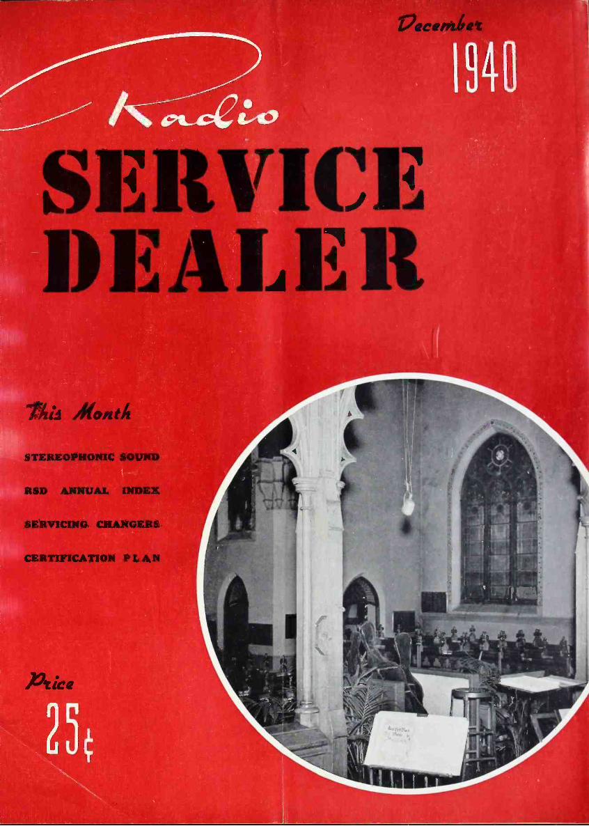
*Packer Memorial Chapel, Lehigh University,Bethlehem, Pa from which the music of thefamed Bach Choir is transmitted by wire lineto a nearby auditorium. Two channels areused, providing two-dimensional sound. Seearticle on page 4.
Published Monthly by
COWAN PUBLISHING CORP.11 WEST 42nd ST., NEW YORK, N. Y.
Telephone: CHickering 4-3278-9
M. L. MUHLEMAN, EDITORS. R. COWAN, ADV. MANAGER
Subscription rate, $2.00 a year in U. S. andCanada; single copies, 25 cents. In foreigncountries, $4.00 a year. Editorial and advertis-ing offices, 11 West 42nd St., New York, N. Y.
VOL. 1 No. 9 * DECEMBER, 1940
1
9.-GeZ4,
DECEMBER 1940 SERVICE - DEALER
Ita/fallen t/YEAREND . . . A new year will haverolled in from the beyond before you seteyes on another issue of RSD. This is agood time, then, to let our mind sweepover the panorama of radio and dish outwhatever catches its fancy . . .
Life has gotten pretty damn complex.The threads of business relations, forinstance, are tightly woven. No onegroup can make a move without mate-rially affecting some other group, andthat hasn't served to improve the na-tional temper. Juke Boxes take moneyout of the pockets of musicians, so maybethe musicians would like to have theJuke Boxes pulled. But, if you pull theJuke Boxes, thousands of specializedservicemen are more than out of pocket-they're out of jobs. We in the radiobusiness are plugging for three- andfour -radio homes, plus a radio in thecar and a fresh -air miniradio as a travel-ing companion. Maybe people will spendso much time listening to the radio thatthey won't have time to read magazinesand go to the movies. So the magazineswill suffer, and Hollywood stars willstart using their real names again.
At first blush, it would seem thatsomeone should rise up in a body anddemand a live -and -let -live policy. Butthings don't work that way. The lessyou mess around with situations, thesooner they clarify themselves. All thingshave a way of seeking their own level.Water does, and so do business rela-tions . . .
After experiencing "Fantasia," we'vedecided we'd like something of the sortin our own home. What we have plannedin moments of thumb -twiddling is fourloudspeakers facing into the living roomfrom north, east, south and west, and a360 -degree fader control system that willpermit us to sweep the room withBeethoven's Fifth or something like thatthere now. It might work out fine withhis (Ludwig's) opus in which a guyblows a horn off in the distance andthen the orchestra comes right back athim.
Somewhere in this phantasmic planthere's the germ of an idea as appliedto phonograph music, but the germ istoo microscopic for our mind's eye . . .
And speaking of that sort of thing-we've always meant to try a two-dimen-sional sound scheme that came to uswhile listening to the campaign speeches
aro gni intfp. dm
IPediul pass
hereby presents to
Vattio*ruira)raterlievo york,ity
this
Certificate of Nonoraryliembershipfor cooperative endeavors in behalf of the
Sadie Servicemen. ofAmerica.
isen ar ekitago,-Xlinois, this fifleentl,slay sk Owns...1940.
Os.irsiss:+1".
...oda .04 name ..d olotjosiwoe pthrdot...
WE'RE PROUD of the Certificate of Hon-orary Membership bestowed on us by theRadio Servicemen of America, for ourcooperative endeavors in their behalf.Our thanks to the RSA-and may we al-ways be a member in good standing!
on the super -national hookups. Thenumerous chain mikes on the speaker'sstand are fairly well separated andshould provide some sort of stereophoniceffect if one were to use two receiversa few feet apart, with one receiver tunedto, say, a Columbia Network station andthe other receiver tuned to an NBC orMutual Network station. The results(if any) obtained would depend upon theseparation of the two mikes feeding thestations to which the receivers weretuned.
Will someone try it out and let usknow if it works? If it does, we'd liketo hear that Presidential chuckle in twodimensions .
As matters now stand in this area,you can hear a few of the many pro-grams you'd like to hear and can hearon a.m. on f.m. also, plus the doubtfuladvantage of a new species of stationannouncer who is scared stiff, has a cold,or talks with his mouth full of hot dog.You can also hear all the flaws in theprograms intended for a -m reproduction,and learn for the first time that yourfavorite commentator has a loose fronttooth.
With many of the f -m stations goingcommercial the first of the year, let's
hope, for the sake of f.m., that sponsorswill develop programs that can live upto the merits of the system . . .
You know, the doctors really haven'ta thing on us. What Latin words havethey got that can compare with "trans -conductance" and "pentagrid converter?"And what could be more confusing tothe layman than "dynamically balancedphase inversion" or, for that matter,"motorboating?" Do you ever say to acustomer, "Does your set motorboat?"If you do, you're nuts. Do the tubes gofishing? Does the oscillator neck? . . .
The coming year may bring a lot ofservicing work on record changers, if esti-mated sales figures mean anything. And,according to local record dealers, the de-mand is almost entirely for DM andMM couplings in album sets-indicatinga very large perCentage of drop mechan-ism playing in this neck of the woods.To clinch matters, the record manufac-turers are having a bit of a time keep-ing up with demand. So, brush up onrecord -changer servicing data-or file thestuff for ready reference if that's theway you do it .
What this country needs-and what athought for the New Year!-is a goodone -buck way of servicing midgets. Ifonly the test -equipment boys could bringout a Midget Analyzer, designed, say,along the lines of a tube tester, thatwould jolly well tell you what waswrong in the shake of a lamb's tail, andwithout one having to peer and prodand fuss and fume. What a market thatwould open up! The nearest thing wehave to it so far is the signal tracer-but, patience! . . .
With the yearend comes the AnnualIndex, which cramps us for space, butyou'll find it of considerable value notonly for reference purposes but also asa panorama of the year's doings anddevelopments. It's good reading matter,even if you aren't looking for somethingspecial. Everything is cross-indexed, soyou can get a pretty good picture ofwhat's what.
We're sorry, of course, that the Indexpushed out the Technical Service Port-folio, but TSF will be back in January.
Well, we -all wish you -all a veryMerry Christmas and a particularlyHappy New Year.
EDITOR
2 RADIO SERVICE -DEALER, DECEMBER, 1940

Announcement:On and alter FEBRUARY 1st, 1941
RADIO SERVICE -DEALER'S > year
Jitiocription rate wit de . . . S 2.00
2 ear ittkeription4 . . 3.0 C
Until Feb. 1st we will accept subscriptions at $1.00 for 12 issues - $2.00 for 24 issues
PAID SUBSCRIBERS MAY EXTEND THEIR PRESENT SUBSCRIPTIONS.
Simply send $1.00 for a 1 year or $2.00 for a 2 year extension.
When RADIO SERVICE -DEALER was first con-ceived it was our opinion that the obligation ofa radio service magazine to its readers shouldinclude a sincere effort to improve andstrengthen the field in all ways. Subsequentlywe have published more and better text ma-terial than any other contemporary publication.
Our staff, working in close contact with thefield will continue to give our subscribers justthe type of authoritative, exclusive and timelydata needed and not obtainable through anyother trade paper.
Now RSD helps better progressive full-timeradio servicing organizations win public recog-nition and a larger share of business through
A
SERVICE -DEALER
ir, II.ER
A distinctly. six-inch de-calcomania lithographedin four colors (red,white, blue and gold)which will help your busi-ness, available FREE toall subscribers classifiedas independent radio serv-ice dealers on request.
(TEAR OUT AND MAIL TODAY)
our nation-wide Certificatio z Plan. Our distinc-five, four-color "Seal of Cortification" is avail-able without charge to any independent servic-ing organization which meets the rigid require-ments but RSD subscribers whom we classifyas "service -dealers" automatically qualify, forwe, at our expense, confirm their eligibility be-fore accepting their subscriptions.
It is a mark of distinction-ft pays-to benumbered amongst RSD's paid subscribers. Youcannot afford to miss the technical data wewill publish or the active campaign now underway for Certified Service -Dealers. Take advan-tage of the money -saving offer still in effect.Send your check and become a paid subscribertoday.
WORTH $1.00 MAIL NOW!Regular $2.00 ANNUAL SUBSCRIPTION TO RSD COSTS BUT $1.00 with this coupon. Good until Feb. 1, 1941.
RADIO SERVICE -DEALER, SOUNDMAN & JOBBER11 West 42nd Street, New York, N. Y.Sirs: Enclosed herewith is my 0 check (or money order) for $ . Please enter my annual subscription order(12 issues) at $1.00 for 1 year or $2.00 for 2 years, (24 issues) -1/2 the regular price. Foreign subscriptions are $2.00yearly. I believe the information given below is accurate. IF MY SUBSCRIPTION IS REJECTED I EXPECT TORECEIVE IMMEDIATELY A REFUND IN FULL FOR THE AMOUNT ENCLOSED HEREWITH.
Name (print carefully)
ADDRESS FIRM NAME Est. 19.. .
CITY STATE
Please check whether firm is
YOUR POSITION
O An independent servicing organizationO An independent service -dealer (engaged primarily in service work)O A service -dealer (does servicing, but is primarily interested in
retailing)O Selling, renting or servicing Sound EquipmentO Jobber 0 Any other classification0 Manufacturer (State it)I belong to a serviceman's organization Yes 0 No
We stock the follow-ing checked items:
O TUBESO PARTSO RECEIVERSO BATTERIES, etc.O SOUND EQUIP.O ELEC. APP'L'S.
O
We own the follow-ing instruments:
O V -T VoltmeterO Tube CheckerO AnalyzerO OscillatorO Signal GeneratorO Volt -Ohm MeterO OthersO MANUALS
RADIO SERVICE -DEALER, DECEMBER, 1940 3
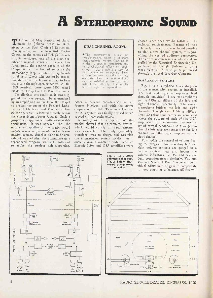
A STEREOPHONIC SOUNDHE annual May Festival of choral
L music by Johann Sebastian Bach,given by the Bach Choir of Bethlehem,Pennsylvania, in the beautiful PackerChapel on the campus of Lehigh Univer-sity, is considered one of the most sig-nificant musical events in America. Un-fortunately, the seating capacity of theChapel is far too limited to serve theincreasingly large number of applicantsfor tickets. Those who cannot be accom-modated sit on the lawns and try to hearthe music through.open windows. At the1939 Festival, there were 1200 seatedinside the Chapel and 1500 on the lawns.
To alleviate this condition it was sug-gested that the program be transmittedby an amplifiying system from the Chapelto the auditorium of the Packard Labo-ratory of Electrical and Mechanical En-gineering, which is located directly acrossthe street from Packer Chapel. Such aproject was approached with considerabletrepidation. It was apparent that thenature and quality of the music wouldimpose severe requirements on the trans-mission system. Another point to be con-sidered was whether the attendance at areproduced program would be sufficientto make the project self-supporting.
DUAL -CHANNEL SOUND
* he accompanying article ontwo-dimensional sound is of morethan academic interest. Covering asit does a specific installation andits psychological effect on audi--nces, it clearly points a way forhe progressive soundman. Two -
_Flannel systems considerably lesselaborate than the one outlinedcan be installed at low cost andwith little difficulty. The resultsfar outweigh the expenditure.
After a careful consideration of allfactors involved, and with the activecooperation of Bell Telephone Labora-tories, a system was finally devised whichproved entirely satisfactory.
A survey of the equipment on themarket showed that no complete system,which would satisfy all requirements,was available. The only possibility,therefore, was to design and assemblethe transmission system locally. As anucleus around which to build, WesternElectric 119A and 118A amplifiers were
639A
MIC
VIATT
639A
(3)CENTERMIC
639Ay, RIGHT
MIC
6A 116AAMP AMP
164 64AMPAMP
VLUVLL VCR
()VR
194AMP
(I)VML VM R
LEFTCHANNEL
I9AAMP
CRYSTALHEADPHONES
60(Y`LADDER
ATT
RIGHTCHANNEL
VIVI
ATT
600"LADDER
ATT
600^. 600"TERMINATIOli TERMINATION
II AAMP
JENSEN594AIB
.,
DYNAMIC3I4HoRN
ATIT
400DIVIDING
NET
vt0---
DUMMYRESISTANCE --.
LOAD
An".
IBA
AMP
400DIVIDING
NET
594A+ JENSEN314 ,e"
MORN DYNAMIC
ORDERWIRE
Fig. 1. Left: Blockschematic of system.Fig. 2. Below: Hori-zontal arrangement
of mikes.
chosen since they would fulfill all thetechnical requirements. Because of theirrelatively low cost it was found possibleto plan a two -channel system, thus pro-viding the desired auditory perspective.The entire system was assembled and in-stalled by the Electrical Engineering De-partment of Lehigh University, usingstock Western Electric parts purchasedthrough the local Graybar Company.
INSTALLATION FEATURES
Fig. 1 is a simplified block diagramof the transmission system as installed.The left and right microphones feedthrough individual 116A pre -amplifiersto the 119A amplifiers of the left andright channels respectively. The centermicrophone bridges the left and rightchannels through two 116A amplifiers.Type 30 volume indicators are connectedacross the outputs of each of the 119Aamplifiers. For monitoring purposes aset of crystal headphones is arranged sothat the left earpiece connects to the leftchannel and the right earpiece to theright channel.
To simplify the control of volume dur-ing the program, corresponding left andright volume controls are ganged in acontrol cabinet that also houses thevolume indicators, i.e. Vs. and Va aredual potentiometers; similarly, Va. andVCR and VAIL and VMR. To permit indi-vidual adjustment of gain to compensatefor any amplifier unbalance, all the vol-
4 RADIO SERVICE -DEALER, DECEMBER, 1940

TRANSMISSION SYSTEM
By IFOR JONES and HENRY C. KNUTSON
Fig. 3. Showing vertical arrangement of cardioid directional microphones in relation to or-chestra and singers.
Diagrams from Western Electric Co.
ume controls have small series connectedcontrols mounted on the amplifiercabinet.
For transmission lines between the twobuildings, simple No. 14 weatherprooftwisted pair run overhead is used. In-side the buildings all wiring is in steelconduit. Tests indicated that the noiseintroduced by the connecting lines is
inaudible.In Packard auditorium, the incoming
lines as shown in Fig. 1, pass through600 -ohm attenuator volume controls to600 -ohm terminations. The 118A poweramplifiers are bridged across these ter-minations. The 600 -ohm attenuators areganged together on a control cabinetthat also houses two volume indicatorsconnected across the output of the am-plifiers. The volume controls on the118A amplifiers themselves are used onlyas compensation controls for balancingpurposes.
Normally, the 118A amplifiers feedinto 400 -cycle dividing networks andthen to the loudspeakers. Each speakerconsists of two units. The low -fre-quency unit is a Jensen 18 -inch dynamic,while, the high -frequency unit is a West-ern Electric 594A loud speaking tele-phone with a 31A horn. Fig. 4 showsthe arrangement of the speakers at thefront of Packard Auditorium during theMay Festival. The distance betweenspeakers is approximately the same asthat between the right and left micro-phones in the Chapel.
Ifor Jones, Conductor of the BachChoir.
'Henry C. Knutson, Associate Professorof Electrical Engineering, Lehigh Univers-ity, Bethlehem, Pa.
A dummy load to replace the loudspeakers is provided as shown in Fig. 1.This permits last minute balancing andtesting with oscillator tone even whenthe audience is present.
The order wire shown in Fig. 1 is
terminated at each end in an, ordinaryheadset and carbon microphone.
MICROPHONE PLACEMENT
One of the major problems involvedwas the placement of the microphones.The compact arrangement of the choirand orchestra as well as the effect of amassive oak rood screen separating theperformers from the audience had to beconsidered. Fig. 2 shows the horizontalarrangement for the Festival, of thechoir and orchestra, while Fig. 3 givesa vertical cross section. To add to thedifficulties was the fact that at no timebefore the final dress rehearsal did theorchestra rehearse with the choir andsoloists. For the choir alone a seriesof listening tests with the microphonesin different positions indicated that thebest reproduction was obtained with theright and left microphones in the planeof the rood screen. Ordinary micro-phones at this point would have resultedin the orchestra overbalancing the choir.
In Bach choral music the balance be-tween the orchestra and the singers iscritical, since both are equally important.It was hoped that the use of the car-dioid pattern of the 639A microphoneswould give a satisfactory compromise.Bearing in mind this cardioid pattern,the left and right microphones wereplaced and tilted as shown in Figs. 2and 3. To the gratification of everyone
concerned, the balance obtained at thedress rehearsal was so nearly perfectthat no further adjustments of the mi-crophones were necessary.
The effectiveness of these 639A micro-phones was strikingly demonstrated at arehearsal of only the orchestra. It wasnoticed that in the reproduced musicthe double -basses which were imme-diately in front of the choir seemed topredominate, while the Novachord(operated at a harpsichord) directly be-low the right microphone was weak. Byinterchanging positions, i.e. placing thedouble -basses almost directly below themicrophone and hence, nearer to its deadzone, and moving the Novachord to-wards the choir, an excellent, balance wasestablished. Full use was made of thethree dimensional cardioid pattern of the639A microphone on the right side. Sincethis microphone was rather close to theorgan it was sl-ifted about a verticalaxis until the organ was nearly in thedead zone.
The center microphone (see frontcover) was used for two purposes, firstto pick up and give proper emphasis tothe soloists, and second, to move forwardthe center of the virtual stage. Stein-berg and Snow* have shown that in atwo -channel auditory perspective system,the center of the reproduced stagerecedes into the background. When theyused a non -directional microphone at thecenter of the pickup stage and bridgedthis across the two channels, they foundthat the whole center of the stage movedinto the foreground. In the Bach Festi-val system, the center microphone was set
(Turn to page 2o)
* Physical Factors, J. C. Steinberg andW. B. Snow, Electrical Engineering, Jan.1934; also in Bell System Technical Jour-nal, Apr. 1934. This paper is one of aseries in a Symposium on Wire Transmis-sion of Symphonic Music and its Reproduc-tion in Auditory Perspective.
Fig. 4. Arrangement of the two loudspeakersets at the front of Packard Auditorium.
RADIO SERVICE -DEALER, DECEMBER, 1940 5
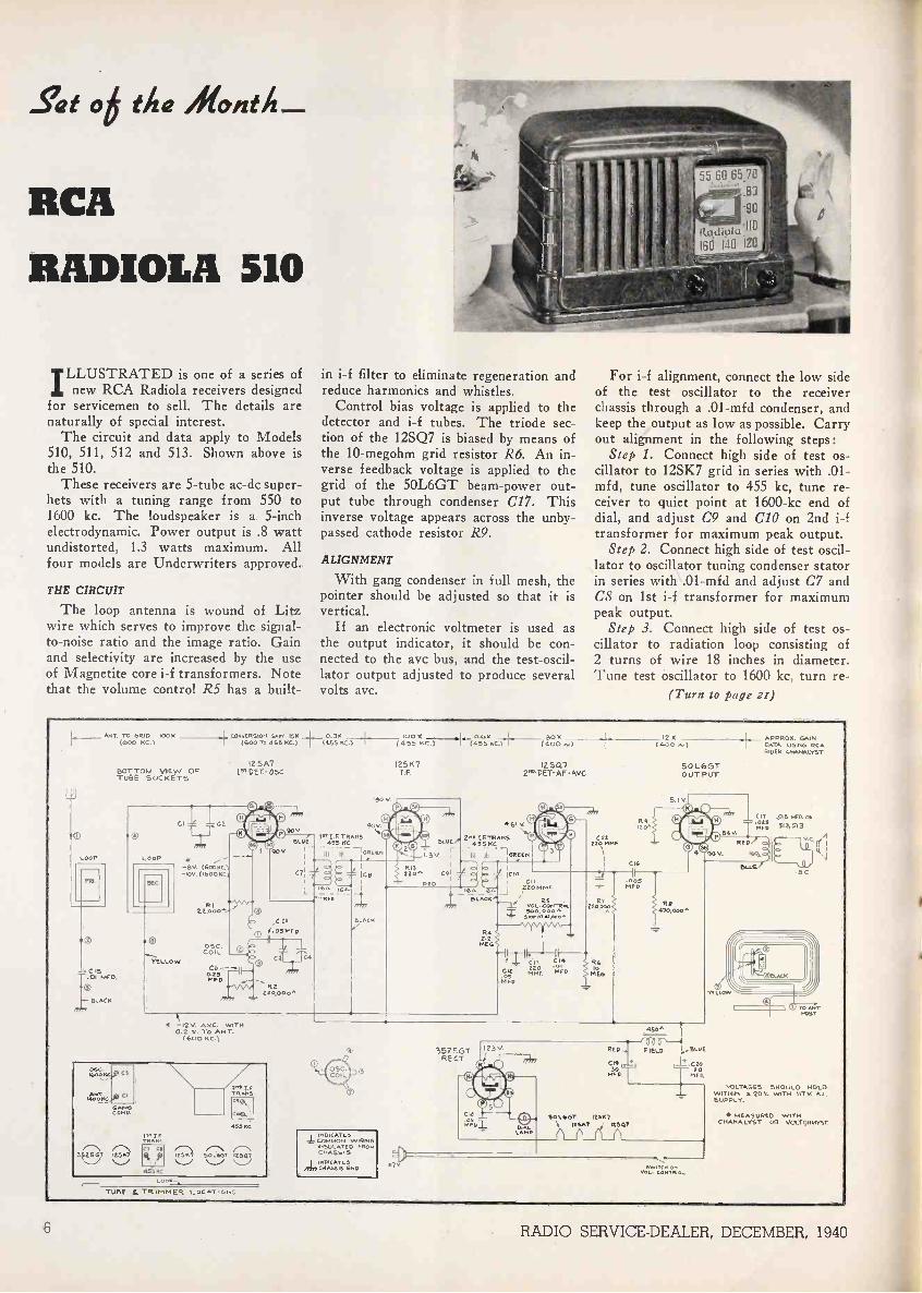
Set of the Month_
RCA
RADIOLA 510
ILLUSTRATED is one of a series ofnew RCA Radiola receivers designed
for servicemen to sell. The details arenaturally of special interest.
The circuit and data apply to Models510, 511, 512 and 513. Shown above isthe 510.
These receivers are 5 -tube ac -dc super-hets with a tuning range from 550 to1600 kc. The loudspeaker is a 5 -inchelectrodynamic. Power output is .8 wattundistorted, 1.3 watts maximum. Allfour models are Underwriters approved.
THE CIRCUIT
The loop antenna is wound of Litzwire which serves to improve the signal-to-noise ratio and the image ratio. Gainand selectivity are increased by the useof Magnetite core i-f transformers. Notethat the volume control R5 has a built-
in i-f filter to eliminate regeneration andreduce harmonics and whistles.
Control bias voltage is applied to thedetector and i-f tubes. The triode sec-tion of the 12SQ7 is biased by means ofthe 10-megohm grid resistor R6. An in-verse feedback voltage is applied to thegrid of the 50L6GT beam -power out-put tube through condenser C17. Thisinverse voltage appears across the unby-passed cathode resistor R9.
ALIGNMENT
With gang condenser in full mesh, thepointer should be adjusted so that it isvertical.
If an electronic voltmeter is used asthe output indicator, it should be con-nected to the avc bus, and the test -oscil-lator output adjusted to produce severalvolts avc.
006570.80
-90
Radioki:110Isd 140 120
For i-f alignment, connect the low sideof the test oscillator to the receiverchassis through a .01-mfd condenser, andkeep the output as low as possible. Carryout alignment in the following steps:
Step 1. Connect high side of test os-cillator to 12SK7 grid in series with .01-mf d, tune oscillator to 455 kc, tune re-ceiver to quiet point at 1600-kc end ofdial, and adjust C9 and C/0 on 2nd i-ftransformer for maximum peak output.
Step 2. Connect high side of test oscil-lator to oscillator tuning condenser statorin series with .01-mfd and adjust C7 andC8 on 1st i-f transformer for maximumpeak output.
Step 3. Connect high side of test os-cillator to radiation loop consisting of2 turns of wire 18 inches in diameter.Tune test oscillator to 1600 kc, turn re -
(Turn to page 21)
J
LOOP
ANT TO GRIDc 100(600
C IS
4- BLACK
,771/1
_ I CONVERSiori GAIN 15.(600 T0 055 KC.)
12 5A7BOTTOM VIEW OF 15TDET- 05CTUBE SOCKETS
Ci
LOOP
SEC
YELLOW
--9v. (6004E1-10V. (1600 NCI
e0er0 0
CZ1,
0.30 11
50 x(4.53 KG.) (455 -1--,:g,30G.)550C.) (400...)
12510 1250.7I.F. 2". DET-AF -AVC
90V90.1',I F TRANS
61.60 455 KC90V
i III IIIeREen
Cl o ICS
164 16^ 1
Ri22 ®
L1
s' 4.05MFD
II05C.COIL
4WDR2
220,000"
C3
/TT
- V. AMC. WITH0.2 V. TO ANT.
(600 KC.)
0.5c14,00KC
ANTMoo me
GONGGANG
WTTRo.e.I
gi)3156' \/ R114550C
ZR.TRANSC14.,
Co.54.
15.5Nel
- /-71252" 54,1,0( 14,..523
TUBE L TRImMER. LOC AT .11,5
Tc4
120-.. C91
RED
221:..;;C111,77
R42.2
MEG
461 V
I.3V5L7' "I''4'11I5117.."5GREEN
CIO
CIL
12 x APPROx. GAIN(400 DATA USING RCA
RIDER CHANALYST
50L6GTOUT PUT
5.1.0 T41 (
04©90 V.
CI220 MINE
RS .
VOL-CONTR.
74;4(
F CC I14CIL .PTFD.5NFL,
71.005RiED
200R7o02
MEG
147 0 .000 ^
Re
C17.02514.1,
.015 UM. Ow512,513
RED
160 W
4
-LINSULATED FROMCHASSIS1.0IGATE5
GOD
450'
RED J FIELD A. BL'E
C19 . I -21 Ca40.1-1-1
HFE
501467 125571ESK7 12507
eLvE/ B.0
VOLTAGES SNOUL 0 HOLDWITHIN S 20% WITH IVEY. A.0SUPPLY.
MEASURED WITHCNA...L.1ST 012 VOLTONNITST.
6 RADIO SERVICE -DEALER, DECEMBER, 1940
Setting' YOUR SERVICES
ITIHE money -making potentialities of
radio service -dealers are brighterthan ever before. There are many rea-sons, chief of which is the ever increas-ing number of radio receivers in thefield. A few years ago there were onlyten million receivers in the U.S.A. To-day there are fifty million, of whichover seven million are auto radios. TheJoint Committee on Radio Research re-ports that nine out of every ten homesin this country have one radio receiver;four homes out of ten own two sets andtwo homes out of ten own four. Everythird car on the highways is radio -
equipped.In January, 1940, over fifty thousand
men were engaged in radio service work,either full or part time. Eight thousandradio retailers operated their own servicedepartments and utilized the services oftwelve thousand men. (In many casesthe dealer was his own serviceman andcould be classified as either a dealer orservicer.) In addition, there were sixteenthousand independent radio servicemenengaged in radio servicing on a full-timebasis. Over thirty thousand other mendid radio service work on a part-timebasis.
THE "PART-TIME" MENACE
These 30,000 part-time radio service-men were (and are) a most disturbingfactor in several regards and they mustbe "cut out" like a cancerous growth. Tobegin with, though they accounted forless than 3% of all radio service workdone, and sold less than 3% of all re-placement tubes and parts; operating asthey did, with practically no overhead,they held to no basic price schedule orminimum scale for services rendered.What few replacement tubes and partsthey used were not turned over at listprices. They usually quoted ridiculouslylow prices to potential customers andthus took business away from legitimatefull-time servicemen and radio retailerswho could not compete on an equitablebasis. Not all, but many of these part-timers frequently resorted to unethicalpractices. Many substituted reclaimed orunreliable replacement parts for nation-ally known and guaranteed brands. Inaddition, generally, their work was notproperly done, nor did they back it upwith a guarantee of satisfaction, a policythat legitimate service -dealers who areestablished in places of business mustinclude as a part of their routine service.
Fortunately for all legitimate parts
First of a Series on the Certified Service -Dealer Plan
manufacturers, jobbers and service -dealers, part-timers and many of theirdemoralizing tactics are quickly passingout of the picture. Needless to state, re-employment and resumption of industrialhiring has gone a long way to help. Theundesirable part-timer may never dis-appear entirely, but if a proper line ofattack is used, the radio servicing indus-try can be made into a very profitableone for all men justly qualified to remainin it. The big job for legitimate servicersand particularly radio parts jobbers is toget part-timers out and keep them out.
JOBBERS CAN HELP
Parts jobbers can do much good byinaugurating rigid discount policies. Anyfull-time servicemen and radio retailerswho maintain definite business establish-ments should be given discount recogni-tion. Even student servicemen should bebarred from discounts. Make themserve apprenticeships as employees oflegitimate servicing organizations untilthey go into business for themselves.Parts jobbers who adhere rigidly to thispractice will gain much more than theylose. Their unit sales will increase, theircredit losses be minimized. Less book-keeping and faster turnover amongstfewer accounts spells lower overhead andbetter profit margins. Part-timers absorbbut a minute portion of a jobber's grossturnover . . . and the business that part-timers would fail to get if they couldnot obtain a full discount will be divertedto full-timers in any event, for full-timeservicemen who do not have to parrywith part-time, chiseling competition willhave more time in which to aggressivelygo after more and better business.
It is our opinion that the lack of confi-dence in radio servicemen as a wholemay be greatly blamed on the unbusi-ness-like methods used by students whoare learning and by part-timers. Theset -owning public has had many sadexperiences and, like an elephant, oncefooled, never forget. The onus unfor-tunately lies on good, reliable servicemenas well.
HOW MUCH BUSINESS?
As stated above, eight thousand dealerswho maintain their own service depart-ments and sixteen thousand full-timeservicemen find themselves with a poten-tial market of 50 million radio receivers
THISESTABLISHMENTIS QUALIFIED
7;dinkaik,Tinancialry
gira ftel
ER,CONFERRED 8 .1 THE THOU TRY LEADING TECHNICAL NIUCATION
1941 k --4.9e,44 SERVICE -DEALER
The new RSD Certification Seal-a distinc-tive six-inch deca comania in red, white,blue and gold, which will help your busi-
ness. Ask for yours now.
which may require servicing, new tubes,etc. Over 42 million sets are more thanone year old and 36 million two or moreyears old.
Let us assume that as many as 10million of these three year -or -older re-ceivers are not worth repairing. Thereare still 26 million potential servicingjobs on "semi -obsolete" models and an-other 18 million "new" sets in the field.Thus, there are 44 million points ofcall left for 24 thousand service -dealers.
Theoretically, every individual radioservice -dealer could anticipate havingapproximately 1850 service jobs withinthe next twelve months. There are morethan 300 million radio tubes in dailyoperation. If only one in every ten werereplaced during the next year, over 30million replacement tubes would be sold,and every service -dealer would, on anaverage, sell 1250 replacement tubes.
Check your records against these fig-ures. Did you, as an individual, service1850 sets and did you sell over 1250 re-placement tubes during the past twelvemonths? If you own a servicing organi-zation and employ two servicemen, doyour books show that your 3 -man organi-zation repaired 5550 receivers and soldover 3750 tubes this last year? If yoursis an average servicing organization inan average city, the above figures shouldrepresent your calendar year's business.
LOOK TO YOURSELF
If you are getting more business thanstated above, more power to you. Keep
(Turn to page .r9)
RADIO SERVICE -DEALER, DECEMBER, 1940 7

STEWART-WARNER RECORD CHANGERService Data On Model J Unit, Used In Latest Combinations
T HE Stewart -Warner Model J RecordChanger plays and automatically
changes 14 or less 10 -inch records or 10or less 12 -inch records. The mechanism isused in the following sets:Radio Chassis Radio Models11-6V 11-6V911-7A 11-7A8 and 11-7A911-8D 11-8D6, 11-8D7, 11-8D8,
11-8D911 -8D -Z 11 -8D6 -Z, 11 -8D7 -D, 11 -8D8 -
Z, 11 -8D9 -Z11-10A 11-10A6, 11-10A8, 11-10A9,
11-10A1011 -10A -Z 11 -10A6 -Z, 11 -10A8 -Z, 11-
10A9 -Z, 11 -10A10 -Z
OPERATIONThe Record Changer is started by turn-
ing the switch control knob 65 (Fig. 4)to "On". This starts the motor and movestrip rod 32 (Fig. 1) which rotates triplever assembly 20 (Fig. 1) causing it to dis-engage from Engagement Clutch Cam 79(Fig. 2). The Engagement Clutch Camwill then rotate due to tension from spring27 (Fig. 1). This causes it to contact thepin on the top side of Drive Gear Assem-bly, 4 (Fig. 1) as it rotates, and inturn, moves the Drive Link Assem-bly, 31 (Fig. 1) and the Selector ShaftCrank Assembly */ and #2 to the posi-tion shown in Fig. 2. Also the tone armreset link 8o (Fig. 2) has moved to whereit has released the latch 18 (Fig. 1), andcarried the tone arm to its extreme out-ward position. The Tone Arm lifter link81 (Fig. 2) has raised the tone arm to its
extreme height, by means of the LifterPlate Assembly 21 (Fig. 1). The tone armis kept from "floating" free by the frictionof the Tone Arm Brake Spring which alsocompresses the tone arm booster spring 13(Fig. 1) due to its very light tension.
The Drive Gear Assembly 4 (Fig. 1)continues to rotate which causes the toppin to disengage from the Automatic En-gagement Clutch Cam which is movedback to latch with the tone arm trip lever,and the lower pin to engage the drive linkassembly, moving it back to its initial posi-tion. This swings in the tone arm to eitherthe 10 -inch or 12 -inch record playing posi-tion and lowers it to the record. At thesame time it releases the Tone Arm BrakeSpring allowing the Tone Arm BoosterSpring to act.LUBRICATION
Motor: The motor is equipped with oil -less bearing and requires no lubrication.
Turntable Spindle Bearings: These arelubricated at the factory and do not re-quire any lubrication for one year. Afterone year they should be oiled with 1 or 2drops of a light grade oil.
The top bearing can be oiled by liftingoff turntable. Make sure when replacingturntable to see that pin in TurntableSpindle slips into slot on bottom surfaceof Turntable hub and also care should betaken not to injure Rubber Idler DriveWheel.
Never under any circumstance allow oilto come in contact with Rubber Idler DriveWheel.
Fig. I. Under -side view of the record changer chassis.
134,) 400 ('7
41)
42
Fig. 2. Adjustment points below chassis.
SERVICE NOTESADJUSTMENT FOR REST POSITION OF TONEARM
Swing tone arm outward until tone armlever assembly 19 (Fig. 1) latches withtone arm latch lever 18 (Fig. 1) which isheld to tone arm shaft 77 (Fig. 1) by twosetscrews.
Make sure these setscrews are tight andthat there is a slight play between the tonearm lever assembly and the panel 5 (Fig.1). This will give proper clearance at ballrace assembly 74 (Fig. 3).
The tone arm lever assembly 19 (Fig.1) is held against tone arm latch lever 18(Fig. 1) by the tension of tone arm locatorlever spring 16 (Fig. 1).
Next loosen the clamping screw in theSwivel Bracket Assembly 46 (Fig. 3).
Now move tone arm 6o (Fig. 4) untilits outside edge is I/8" from the outsideedge of the panel 5 (Fig. 1) and retightenscrew securely.RECORD CHANGER DOES NOT Go INTO ITSCHANGING CYCLE AT END OF RECORD
Worn or Damaged Stop Groove: If thestop groove in the record is worn out ordamaged, discard such a record.
Cut -Off Adjustment May Be Incorrect:The Record Changer should go into itschanging cycle when the needle enters thestop groove and has traveled to within adistance of 174" from the center of theturntable shaft.
If the Record Changer does not go intoits changing cycle when the needle hasreached the above mentioned distance, theTone Arm Trip Lever Shoe 23 (Fig. 1)should be moved toward the outside edgeof the panel. To do this, it is necessaryto loosen the thumb nut 22 (Fig. 1) andthen retighten after adjustment has beenmade.
If the Record Changer goes into itschanging cycle before the needle hasreached a distance of 17/8" from the centerof the turntable, the Tone Arm Trip LeverShoe should be moved inward toward thecenter of the Record Changer.RECORD CHANGER DOES NOT Go INTO ITSCHANGING CYCLE WHEN SWITCH KNOB ISTURNED ON
When the switch is turned to "On" the
8 RADIO SERVICE -DEALER, DECEMBER, 1940

Record Changer snould start its changingcycle. If it does not, the following pointsshould be checked.
Make sure motor is running.Check Trip Rod 32 (Fig. 1) to make
sure it releases Trip Lever Assembly zo(Fig. 1) from Engagement Clutch CamAssembly 79 (Fig. 2) when Switch Knobis being turned on. If Trip Lever Assem-bly is not released, Trip rod should beshortened by bending until Trip Leverclears Engagement Clutch Cam Assembly,when Switch Knob is turned.
Make sure that Clutch Reset Pawl io(Fig. 2) clears Drive Link Assembly 3r(Fig. 1).RECORD CHANGER CONTINUES TO REPEAT ITSCHANGING CYCLE WITHOUT PLAYINGRECORDS
Trip Lever Assembly 20 (Fig. 1) doesnot latch in Engagement Clutch Cam As-sembly 79 (Fig. 2) which may be due tocauses listed below:
Trip Rod 32 (Fig. 1) may be bent sothat it is too short, holding Trip LeverAssembly from contacting EngagementClutch Cam Assembly.
Springs 24 or 35 (Fig. 1) may be dis-connected.No SOUND WHEN NEEDLE IS ON MOVINGRECORD
Muting switch 26 (Fig. 1) may be outof adjustment. The contacts of this switchshould be open whenever its long blade isnot resting on the shoe of the EngagementClutch Cam Assembly 79 (Fig. 2). If thecontacts remain closed after the long bladehas left the shoe, they should be adjustedby bending until there is a separation ofapproximately 1/32".
Switch should be checked to make surecontacts are closed when long blade isresting on the shoe of the EngagementClutch Cam Assembly.
The lugs on the Muting switch mayhave been bent together.
Pickup cartridge in Tone Arm may havebeen damaged or may be defective.
TONE ARM ADJUSTMENTS FOR 12" RECORDS
Turn both Control Knobs until the ar-rows marked "12" are pointing toward thecenter of the turntable.
Place a twelve -inch record on the turn-table.
Start Record Changer and note whereneedle contacts record. Correct contactingis about %" from the outside edge ofrecord.
Set Rod 56 (Fig. 3) is operated by Se-lector Arm 61 (Fig. 4). The 12" Set Link10 (Fig. 1) operates as a stop when RecordChanger is set for 12" records. WhenTone Arm Locator Assembly 12 (Fig. 1)contacts 12" Set Link the Tone Arm shouldbe in the correct position to play a 12"record.
If at this point, the position of ToneArm is incorrect, loosen the screw whichholds the Tone Arm Locator Shoe 12" 14(Fig. 1) and move in either direction asrequired and tighten screw.
TONE ARM ADJUSTMENTS FOR 10" RECORDS
Turn both Control Knobs until the ar-rows marked "10" are pointing toward thecenter of the turntable.
Place a 10" record on the turntable andstart Record Changer.
Note where needle contacts record. Cor-rect contacting is about 1/8" from the out-side edge of record. If contacting of needleis not correct as mentioned, loosen thescrew which holds Tone Arm Locator Shoe10" z5 (Fig. 1) and slide shoe in or outas required, then tighten screw.
Fig. 4. Points of adjustment and operationabove chassis.
TONE ARM HEIGHT ADJUSTMENTSSet the Record Changer for ten -inch
records, turn Switch to "On" and allowRecord Changer to go through a changingcycle with no record on the Turntable.The clearance between Turntable and thebottom surface of the Tone Arm shouldbe approximately 1/8". Usually this clear-ance can be obtained by adjusting theTone Arm Adjustment Screw 70 (Fig. 3).It is well to check the following points be-fore making any adjustment:
Check clearance between Roller 51 (Fig.3) and. Selector Crank Shaft Assembly 7(Fig. 1). There should be approximately1/32" clearance at this point. If the clear-ance is greater, it would be due to thepressure on the Spring Washer 5o (Fig. 3)being too great. This will prevent theTone Arm Lifter Reset Spring 82 (Fig. 3)from returning the Tone Arm Lifter LinkAssembly 8./ (Fig. 2) sufficiently. To re-lieve the pressure on the Spring Washer,lower the Selector Shaft Collar 6 (Fig. 1)slightly.TONE ARM LOWERS ON RECORD TooSUDDENLY
If the Tone Arm lowers too suddenly,the Spring Washer 5o (Fig. 3) which islocated between the Tone Arm Lifter Link
Assembly 8i (Fig. 2) and Selector ShaftCrank Assembly Post 7 (Fig. 1) is notunder sufficient pressure. The setscrews inthe Selector Shaft Collar 6 (Fig. 1) shouldbe loosened and the Selector Shaft Collarpressed upward slightly and set screwstightened.NEEDLE DRAGS ACROSS RECORD
If the needle drags across the record,the long portion of the Tone Arm LeverAssembly 19 (Fig. 1) is contacting the pinon the top side of the gear assembly 4(Fig. 1) and is being moved by it. Theremedy is to bend the long portion of theTone Arm Lever Assembly upward so thatit clears the pin. In some radio modelsthe lever may be reached without remov-ing the record changer from the cabinet;however, if easy access is not possible, re-moval of the complete record changer isrecommended.TONE ARM LANDS IMPROPERLY ON BOTH10" AND 12" RECORDS
If the Tone Arm lands improperly onone size of record but properly on theother size, the Tone Arm adjustments for12" or 10" records, previously described,should be made. Improper landing on both12" and 10" records is due to a dislocatedTone Arm. This may be remedied byloosening the screw located on the ToneArm Swivel Bracket 46 (Fig. 3) and mov-ing the Tone Arm to the proper positionand then retightening the screw. A roughcheck as to the proper position is to placethe Tone Arm in its rest position and seeif the outside of the Tone Arm is flushwith the edge of the Motorboard. The twoset screws on the Tone Arm Shaft 77 (Fig.2) should be checked to see if they aretight.
STEWART-WARNER '40 CHANGERS
Spindle SqueakSqueak due to records rubbing on turn-
table spindle in any of the Stewart -Warner1940 Series Automatic Record Changerscan be eliminated by gently lining up thestack of records.
Fig. 3. Close-up view, showing points of adjustment.
RADIO SERVICE -DEALER, DECEMBER, 1940 9
mustache and some more hair spoutingout of his chin. Not enough to call it aVandyke beard, but a reasonably ac-curate facsimile.
He noticed I was lugging the recorder,and got excited right off the bat.
"Where's Jerry?" he shouted. "Heknew I was depending upon him!" Hesure seemed sore.
"Sorry, doctor, Jerry had to go to thedentist, but I assure you I am perfectlycompetent to hook up this recorder." Iknew he was no doctor but handing outa title that way sometimes calms themdown. Not this time, though.
"I know you can hook it up," hesnapped. "I can hook it up. My secre-tary can hook it up. That's not theproblem. Jerry helps my business, buthe doesn't know it. But you-" Herushed to answer the phone.
I wished I had never seen the guy.Believe me, the next time Jerry tries toshove his dirt over on my side there'sgoing to be trouble.
I unpacked the outfit and set it on thetable. Then I plugged in the mike andstarted to make a test recording.
"One, two, three, four. Mary had alittle lamb . . ." I muttered my littlespiel into the mike. While playing itback, a girl entered the room. She tossedme a smile and a good morning and I
Setvieemanffl PlatyTUESDAY.-Teachers are usually a
little bit nuts; especially men teachers.And when you run across one whoteaches elocution-boy, you've strucksomething! At least, we did.
Jerry calls him Spouter-he talks somuch. Myself, I hadn't met him untiltoday. But the name fits.
It started about six months ago, whenJerry got the bright idea of running arecorder over to the guy's studio andmaking some records of pupil's voices.He sold Spouter on the idea of recordingthe progress of students by means ofthe records. In turn, Spouter, no dope,got three additional sales of recorders todoting mamas who wanted additionalrecords of their kid's voices and, inci-dentally, of their own. And, today, an-other prospective sale.
Naturally, Jerry usually handles thesejobs. He got the bird started. But hehad to stop at the dentist's on the wayand phoned me to run the recorder overto Spouter's studio.
The studio is in the residential section,in a private house. I expected to findit in an office building of some sort andnearly passed it by. But a sign "VoiceCulture" in the front window caught myeye, so I knew I had the right place.
He answered the ring himself-a sortof skinny -looking guy with a small, black
EDGAR()US f /
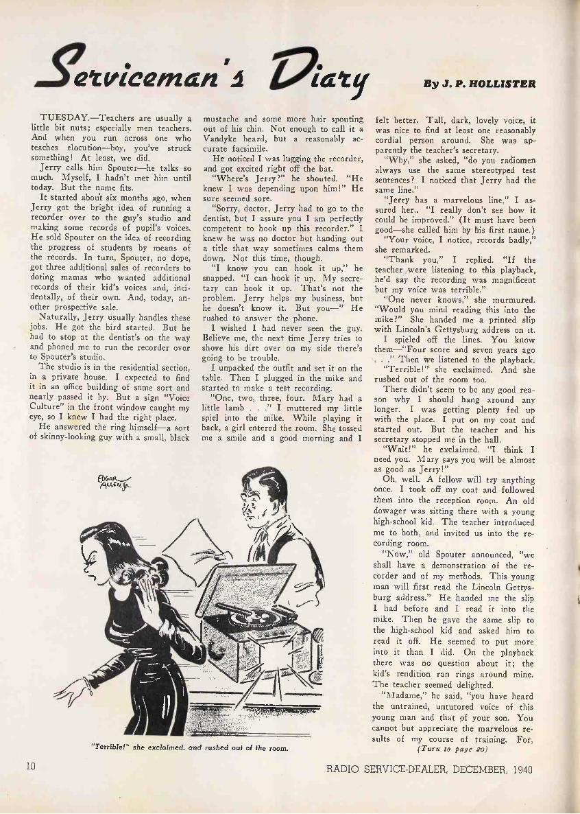
"Terrible!" she exclaimed, and rushed out of the room.
By J. P. HOLLISTER
felt better. Tall, dark, lovely voice, itwas nice to find at least one reasonablycordial person around. She was ap-parently the teacher's secretary.
"Why," she asked, "do you radiomenalways use the same stereotyped testsentences? I noticed that Jerry had thesame line."
"Jerry has a marvelous line," I as-sured her.. "I really don't see how itcould be improved." (It must have beengood-she called him by his first name.)
"Your voice, I notice, records badly,"she remarked.
"Thank you," I replied. "If theteacher ,were listening to this playback,he'd say the recording was magnificentbut my voice was terrible."
"One never knows," she murmured."Would you mind reading this into themike?" She handed me a printed slipwith Lincoln's Gettysburg address on it.
I spieled off the lines. You knowthem-"Four score and seven years ago. . ." Then we listened to the playback.
"Terrible!" she exclaimed. And sherushed out of the room too.
There didn't seem to be any good rea-son why I should hang around anylonger. I was getting plenty fed upwith the place. I put on my coat andstarted out. But the teacher and hissecretary stopped me in the hall.
"Wait!" he exclaimed. "I think Ineed you. Mary says you will be almostas good as Jerry!"
Oh, well. A fellow will try anythingonce. I took off my coat and followedthem into the reception room. An olddowager was sitting there with a younghigh-school kid. The teacher introducedme to both, and invited us into the re-cording room.
"Now," old Spouter announced, "weshall have a demonstration of the re-corder and of my methods. This youngman will first read the Lincoln Gettys-burg address." He handed me the slipI had before and I read it into themike. Then he gave the same slip tothe high-school kid and asked him toread it off. He seemed to put moreinto it than I did. On the playbackthere was no question about it; thekid's rendition ran rings around mine.The teacher seemed delighted.
"Madame," he said, "you have heardthe untrained, untutored voice of thisyoung man and that pf your son. Youcannot but appreciate the marvelous re-sults of my course of training. For,
(Turn to page 2o)
10 RADIO SERVICE -DEALER, DECEMBER, 1940

postal Telegraph 5'04)kcto minions ...
Raytheon engineers make auimportant contribution in over-coming delays caused by adverse
weather conditions.
How to save seconds of time! How to counteract interruptions causedby snow, sleet, hail, electric storms and aurora borealis! How to improveservice in every way! These are problems constantly before Postal Telegraphexecutives. Much time and money have been invested to solve them.
In cooperation with them, RAYTHEON engineers developed equip-ment, incorporating a Postal Telegraph invention, a revolutionary relayunit, in which RAYTHEON tubes play a vital part. These tubes are inconstant service, 24 hours day in and day out. With their use, fadingelectric impulses are picked up, amplified, and messages speeded throughfaster than was ever before possible where weather is a factor.
Hundreds of these units have already been installed in Postal Telegraphoffices throughout its nationwide system and millions of patrons are bene-fitted thereby. During the severe electrical disturbance caused by auroraborealis on Easter Sunday, 1940, while ordinary circuits were disrupted thecircuits equipped with RAYTHEON apparatus were unaffected. ThusPostal Telegraph rendered excellent service during a period in which otherservices were interrupted.
The same engineering genius which helped Postal Telegraph solve oneof its baffling problems goes into every tube in the RAYTHEON LINE.That's why RAYTHEONS give such superb service wherever installed.And that's why RAYTHEON service -men and dealers everywhere are build-ing goodwill, bigger business, and bigger tube profits by making replace-ments with RAYTHEONS.
These RAYTHEON advantages are now open to you . . . benefits youmay enjoy with smaller stock of tubes, because you need only one line.For RAYTHEON makes them all . . . and they cost no more! YourRAYTHEON Distributor has an unusual tube deal for you. See himwithout delay.
WORLD'S LARGEST EXCLUSIVE RADIO
Postal Telegraph's head-quarters station in Chi-cago. One of the largestoperating rooms in theworld. 28 RAYTHEONunits installed here.
One of the RAYTHEON unitsnow standard equipment inhundreds of Postal TelegraphStations. Note the 4 RAY-THEON Tubes.
-111111111111 111111111FAI
f,
MAKES1
THEM ALL
NEWTON, MASS. NEW YORK CHICAGOSAN FRANCISCO ATLANTA
TUBE MANUFACTURERS
RADIO SERVICE -DEALER, DECEMBER, 1940 11

Issue Paq.ALIGNMENTSee "Servicing"
ANTENNAS
AutoChrysler Skyway Antenna Installation.Aug.Hudson Vacuum Aerial June
Frequency ModulationStromberg-Carlson F -M, A -M Ant
Connections July
MasterMaster Antenna Systems,
by Carl Goudy June
LoopLoop Feedback Sept.Store Demonstration of Loop Sets .. . Nov.Zenith Wavemagnet May
AUDIO AMPLIFIERS
ApplicationsCathode Follower Apr.Impedance Matching,
by Maurice Apstein Nov.Practical Use of Inverse Feedback,
Part I, by Maurice Apstein Apr.Practical Use of Inverse Feedback,
Part II, by Maurice Apstein MayPuppets Are Sound Sales Prospects Aug.
TestingChecking Audio Circuits Aug.Checking Phase Inverters JuneDetermining Amplifier Gain Oct.Testing Audio Amplifiers.... Sept.The Frequency Record as a Servicing
Tool, by Zeh Bouck Apr.
CircuitsCathode Follower Apr.Direct Coupling MayDynamic Coupling Nov.Inverse Feedback MayPhase Inverters Apr.Phase Inverters June
BATTERIES
Help Standardize Dry -Cell Types.... June
BATTERY OPERATIONAutomatic Battery -Line Switching.... myBattery -Line Switching N ov.
BATTERY SETSRCA Victor BP -10 Personal Aug.
BOOK REVIEWSFrequency Modulation, by John F
Rider MayPerpetual Trouble Shooter's Manual,
Vol. XI by John F. Rider Aug.Practical Radio Communication, by
Nilson and Hornung Dec.Radio Operating Questions and An-
swers, by Nilson and Hornung Dec.RCA Ham Guide. Nov.RCA Receiving Tube Manual MayThe Oscillator at Work, by John F
Rider MayThe Meter at Work, by John F. Rider Dec.
BUSINESS ARTICLESGo On Record With Sound Effects...Oct.Help Standardize Dry -Cell Types ....JuneNow-"Certified Service -Dealers" Nov.Profits in Master Antenna Systems,
by Carl Goudy JunePuppets Are Sound Sales Prospects Aug.Selling Your Services Dec.Servicing Contacts, by R. G. Ellis Oct.Sound For Movie Makers, by H. M
Guthman Aug.The Big Shift Apr.The Show in Review JulyThey Need Needles Apr.Test Your Lines For Profit, by J. P
Kennedy MayTouch Up Those Cabinets Sep.True Confession of a Service En-
gineer, by Edgar Jannivere Nov.Unique Radio Hospital Oct.
RADIO SERVICE -DVIssue Page
April to Decei
Issue PageCABINETS
test Your Lines For Profits, by J.P. Kennedy May 18
Termination Impedance .JuneThe Cathode Follower Apr.Tubes and Circuits Oct.
197
12Touch Up Those Cabinets Sept. 10
INDICATORSCIRCUITS Testing
21 Also see "Circuit Court" Frequency Modulation Field Problems,29 Audio by E. T. Higgons. MayIndicators For Signal Tracers and
12
See "Audio Amplifiers" Analyzers, by Harper Johnson Oct. 6
17ReceiverEmerson Model 365 Hi-Fi Receiver...Nov. 16
Phono Servicing JulyServicing by Signal Tracing MayStroboscope Disc. May
47
19Meissner F -M Receptor Apr. 17 Test Oscillator Applications June 13Motorola Model 40-60W Sept. 14 Testing Audio Amplifiers Sept. 11RCA Radiolas 510, 511, 512, 513....Dec. 6 Vacuum -Tube Voltmeters Aug. 9
4 RCA Victor BP -10 Personnal Aug. 6Setchell Carlson "Dor-A-Fore" Oct. 8 Volume
16
Stromberg-Carlson No. 425 F -M Set MayWilcox -Gay A-70 Recordio Apr.
1322 Instantaneous Sound Recording, Part
II, by F. H. Goldsmith June 61822 CIRCUIT COURT Speaker Protection Apr.
Volume Indicator June1319
Automatic Filament Feed July 10 Wilcox -Gay A-70 Recordio Apr. 23Battery Switching Nov. 17Cathode -Energized Filament Strings Dec. 16 INSTANTANEOUS RECORDING
7
Compensated Feedback Oct.Contact Potential Bias Apr.Degenerated Tone Control Aug.Delayed AVC July
16121710
See "Recording"
INVERSE FEEDBACK5 Direct -Coupled Push -Pull Circuit May 34 Balanced Phase Inverter Apr. 12
Double Tone Control Nov. 17 Cathode Follower Apr. 78 F -M Alignment June 19 Compensated Feedback Oct. 16F -M "Bandspread" Oct. 16 Degenerative Tone Controls Aug. 1714 F -M Improvements Dec. 16 Inverse Feedback Nov. 1014 F -M Tricks Oct. 16 Practical Use of Inverse Feedback,Hum Neutralization Sept. 16 Part I, by Maurice Apstein Apr. 8Loop Feedback Sept. 16 Practical Use of Inverse Feedback,
1115
911
10
No Grid Condenser? MayOscillator Drift Correction Aug.Phase Inverter Apr.Resistance -Coupled R. F MayR -F Degeneration Sept.Simplified Tone Control Aug.Speaker Protection Apr.Termination Impedance June
2217122216171319
Part II, by Maurice Apstein MayR -F Degeneration \ Sept.
MICROPHONESMicrophone Ratings Sept.Setchell Carlson "Dor-A-Fone" Oct.Wilcox -Gay A-70 Recordio Apr.
1416
138
23Tone Control Apr. 13
7 Tuned-Untuned R -F Stage Nov. 17 NEEDLES3411
Volume Indicator JuneWavemagnet May
1922
See "Phonograph"1412 COMPENSATION PHONOGRAPH15 See "Tone Compensation" Compensation
See "Tone"CONDENSERS
8 Data on Condensers, by J. M. Borst-July 11 MotorsElectrolytic Symbols Aug. 20 Eliminating Rumble July 5Motorola Condenser Symbols Sept. 18 Motorola B2RC, B3RC, B4RC Record
Changers Aug. 181017
CUTTERSInstantaneous Sound Recording, Part
RCA Model U-9 Apr.RCA Phono Motor Identifying Colors Oct.RCA VA -21 Sept.
201820II, by F. H. Goldsmith June 6 RCA Victor Governor ControlledWilcox -Gay A-70 Recordio Apr. 22 Motors Apr. 21
6 FENCE CONTROLLERSRCA Victor RP -152,-153 Record
Changers Oct. 17Stewart -Warner Model J RecordElectronic Gadgeteering in Fence Con- Changer Dec. 8trollers July 8Needles33 FREQUENCY MODULATION Inserting Needle in RCA Top -Loading
27 Circuits Pickups Nov.They Need Needles Apr.
185
17 F -M "Bandspread" Oct.F -M Tricks Oct.
1616 Records
1728
Meissner F -M Receptor Apr.Oscillator Drift Correction Aug.
1717
Frequency Test Records Apr.Instantaneous Records May
104
34 Stromberg-Carlson No. 425 Receiver.. May 13 Phono Servicing July 4Playing Sequences Oct. 18
33 Servicing Sound Effects Records Oct. 517 F -M Alignment June
Frequency Modulation Field Problems,19 Record Players
by E. T. Higgons May 12 Motorola B2RC, B3RC, B4RC Record5
Meissner F -M Receptor Apr. 17 Changers Aug.RCA VA -21 Wireless Record Player Sept.
18208
14 Theory RCA Victor RP -152,-153 RecordChangers Oct. 17Balanced Rectifier Dec. 16 RCA Victrola Model U-9 Apr. 20
5 Tuning Indicator Dec. 16 Sound For Movie Makers, by H. M.14 Double Limiter Dec. 16 Guthman Aug. 8
7 Double Superheterodyne Dec. 16 Stewart -Warner Model J Record13 F -M Improvements Dec. 16 Changer Dec. 8
814
Frequency Modulation Field Problems,by E. T. Higgons May
How Wide -Band F.M. Reduces Noise,12 PICKUPS
65
1810
by John H. Potts Sept.
IMPEDANCE MATCHINGImpedance Matching, by Maurice Ap-
6 GeneralMixing and Fading Aug.Phono Servicing JulyRCA Victor Top -Loading Pickups Nov...
84
18
6stein Nov.
Sound Facts For Sound Men, by J. P5 Compensation
23 Kennedy Aug. 4 Emerson DV -364 Oct. 16
12 RADIO SERVICE -DEALER, DECEMBER, 1940
Test Oscillator ApplicationsU -H -F Test OscillatorVacuum -Tube Voltmeters
:n ANNUAL INDEXInclusive
Issue PageFarnsworth AK -58, AK -59 Apr. 20Phono Servicing July 4
RCA Victor Tone Guard Sept. 18
Stewart -Warner 01-6B9 May 24Stromberg-Carlson No. 460-PF June 21Stromberg-Carlson No. 470 July 17They -Need Needles Apr. 5
Tone Compensation Aug. 20
Service NotesDistortion MayMotorola B2RC, B3RC, B4RC Record
Changers Aug.Phono Servicing JulyRCA Top -Loading Pickups Nov.RCA Victor RP -152,-153 Record
Changers Oct.Stewart -Warner Model J Record
Changer 'Dec.
Stewart -Warner 01-6B9 May
PUBLIC ADDRESSCutting P -A Corners Aug.Dual -Turntable Record Player Apr.Frequency Records As Service Tools Apr.Go On Record With Sound Effects Oct.Impedance Matching, by Maurice
Apstein Nov.Practical Use of Inverse Feedback,
Part I, by Maurice Apstein Apr.Practical Use of Inverse Feedback,
Part II, by Maurice Apstein MayPuppets Are Sound Sales Prospects Aug.Sound Facts For Sound Men, by J. P
Kennedy Aug.Sound System at Elwood Sept.Speaker Protection Apr.Stereophonic Sound Transmission, by
Ifor Jones and H. C. Knutson Dec.Testing Audio Amplifiers Sept.The Cathode Follower Apr.
RECEIVERSEmerson Model 365 Hi-Fi Receiver Nov.Meissner F -M Receptor Apr.Motorola Model 40-60W Sept.RCA Radiolas 510, 511, 512, 513 Dec.RCA Victor BP -10 Personal Aug.Setchell Carlson "Dor-A-Fone" Oct.Wilcox -Gay A-70 Recordio Apr.
RECORDSSee "Phonograph"
RECORD CHANGERSSee "Phonograph"
RECORD PLAYERSSee "Phonograph"
RECORDINGInstantaneous Sound Recording, Part
I, by F. H. Goldsmith MayInstantaneous Sound Recording, Part
II by F. H. Goldsmith JuneStroboscope Disc For 33% & 78 RPM MayWilcox -Gay A-70 Recordio Apr.
SERVICING
EquipmentFrequency Record as a Service Tool,
by Zeh Bouck Apr.Indicators For Signal Tracers and
Analyzers, by Harper Johnson Oct.Servicing Contacts With Cleaners, by
R. G. Ellis Oct.Signal Tracers MayStroboscope Disc May
JuneMayAug.
MethodsAligning F -M Receivers Apr.F -M Receiver Alignment MayMake Your Test Oscillator Pay, by
Billy Parker Sept.Making Frequency Runs On A -F
Amplifiers Apr.Servicing By Signal Tracing MayServicing With Test Oscillator JuneServicing With V -T Voltmeters Aug.Signal Tracers and Signal Analyzers .Oct.Simplified F -M Alignment JuneUsing the Square -Wave Generator Sept.
SET OF THE MONTHSee "Receivers"
SHOP NOTESCrosley 689, 729 Alignment Precau-
tion June 21Crosley J-7739, 7739 Differences May 24Electrolytic Symbols Aug. 20Emerson 8MT-574 Phono Converter . Oct. 19Emerson EC, EM, DB, DL, DW Dial
Cord Replacement Aug. 20Fada P58, PL58 Tube Substitution July 17Farnsworth AK -58, AK -59 Changes Apr. 20
24 Farnsworth BC -72,-80 Improvements Apr. 20Galvin Motorola Aerial Check May 24
18 Galvin Wireless Record Player Tuning4 Error May 24
18 G.E. HJ-514 Alignment Precaution. Apr. 20G.E. HM -80A, 85A, 136A Osc. Drift
17 Correction Aug. 20G.E. J501, -W, J502, -W Changes Oct. 19
8 Hudson Auto SA -40, DB-40 Sensitiv-24 ity Apr. 20
Hudson Motor SA -40, DB-40 AntennaChoke Dec. 14
Miniature Tubes: Removal Precau7 tion Aug. 20
8 Motorola AC -DC Alignment Apr. 20
10 Motorola Condenser Symbols Sept. 18
5 New Tubes: 5W4GT, 1LC5, 1LC6,1LD5 Sept. 18
5 New Tubes: 3S4, 12A6 Dec. 14Philco 37.38 Intermittent Aug. 20
8 Philco 39 -31 -Dead Nov. 18Philco 40-110 Pushbutton Failure Oct. 19
14 Philco 40-115, 124 Series -Squeals. . Nov. 18
14 Philco 40 -124 -Dead Oct. 19Philco 41-90 Squeals Aug. 20
4 Philco 41KR-Hum Oct. 19
8 Philco 610 Distortion Oct. 19
13 Philco Transitone PT25-Noisy Oct. 19Philco Transitone PT45-Dead Oct. 19
4 Phono Xtal Pickup Distortion May 24
11 RCA Gain Data Sept. 187 RCA Little Nipper Speaker Adjust.
ment Sept. 18RCA Loop Sets: Store Demonstration .Nov. 18RCA Phono Motors Oct. 18RCA Power Transformer Replacement. Oct. 19RCA Tone Guard Sept. 18
Governor Phono Motor Apr. 21RCA Victor Top Loading Pickups Nov. 18RCA Victrola U-9 Phono Mechanism Apr. 20RCA BP -10 Lid Replacement Dec. 15RCA K-80 Hum Modulation Dec. 15RCA QU2C, QU2M, QU3C, QU3M
Howl Dec. 15RCA QU5 Radio Breakthru on Phono. Nov. - 18RCA R -103-S Tone Compensation . . . . Aug. 20RCA RP -152 Record Changer Stalling .Dec. 14RCA T63, U-48 Calibration Apr. 20RCA V-300,-1,-2 Phono Gain Nov. 18RCA VA -21 Wireless Record Player
Motor Data Sept. 20RCA 10X Hum Dec. 14RCA 14BT, 14BT-2, 14BK Distortion .Dec. 14RCA 15BP Fidelity change Nov. 18RCA 15BP Power Switch Replace-
ment Sept. 20RCA 16K, 16T3 Police Band Sept. 18
4 RCA 16K, 111K Oscillator Failure Sept. 18RCA 16K, 16T2, 16T3, 16T4, 17K,
6 19K, V-205, V -405 -Increasing Sensi-19 tivity Dec. 14
22 RCA 45X-11,-12,-13 Osc. Coil Connec-tions Dec. 14
RCA 45X11,-12,-13 (2nd Production)Revisions Dec. 15
RCA 46X21,-23 Osc. Coil Connections .Nov. 18RCA 156 Tube Tester Dec. 15RCA 1941 Receivers -Reducing Sensi-
10 tivity Sept. 18Record -Playing Sequences Oct. 18
6 Sparton 590-1 Circuit Change Apr. 21Stewart -Warner Loop Alignment Sept. 20
13 Stewart -Warner Wiring Color Code June 217 Stewart -Warner 01-5D Phono Precau-
19 tion May 2413 Stewart -Warner 01-6B9 Phono Notes May 2412 Stewart -Warner 01-6C9 Tone Control
9 Changes June 21Stewart -Warner 01-81, 08-81 Hum Apr. 21Stewart -Warner 02-42 Oscillation Apr. 21Stewart -Warner 03-6N Hum Dec. 15Stewart -Warner 07-31 Oscillation May 24Stewart -Warner 11-5V Circuit Change Dec. 15
5 Stewart -Warner 11-7A Microphonics andRumble Dec. 15
Stewart -Warner 11-10A, 11 -10A -ZAudio Howl Dec. 15
Stewart -Warner 12-4D Oscillation Dec. 15Stromberg-Carlson FM -AM Antenna
Connections July 17Stromberg-Carlson 400 Series Dial
Pointer July 17Stromberg-Carlson 460-PF Phono Com-
pensation June 21Stromberg-Carlson No. 470 Phono Com-
pensation July 17
Issue Page
161714
668
22
1712
107
1396
1921
Issue PageStromberg-Carlson 505, 515 F.M.-
Weak or No Signal Dec. 15
Stromberg-Carlson No. 509 ServicingOct. 19Data
Wells -Gardner Tuning Eye Distortion May 24Wells -Gardner 1A29 "B" Issue -Hum
Modulation May 24Wells -Gardner 5D2, 6A26, 6A27
Hum June 21
Hum Reduction June 21
Zenith 1940 Advance Line ServiceNotes Aug. 20
Zenith 1940 Line General Notes July 17
Zenith 1941 Receiver NumberingSystem Nov. 18
Zenith 1941 Receiver Service Notes Sept. 20Zenith 1941 Wavemagnets Sept. 20
SIGNAL GENERATORSSee "Servicing Equipment"
SIGNAL TRACINGSee "Servicing"
SOUNDs / 'irbtie Address"
SOUND EFFECTSSee "Phonograph Records"
TECHNICAL SERVICE PORTFOLIOSection I -Servicing by Signal
Tracing May 7Section II -Test Oscillator Applica-
tions June 13Section III -Data tiTott Condensers July 11
Section IV -V -T oltmeters Aug. 9
Section V -Testing Audio Amplifiers Sept. 11
Section VI, Part.1-Tubes andCircuits Oct. 9
Section VI, Part II -Tubes andCircuits Nov. 9
TESTINGSee "Servicing"
TEST OSCILLATORSSec "Servicing Equipment.'
TEST EQUIPMENTSee "Servicing Equipment"
TONE
CompensationCompensated Feedback Oct. 16Degenerative Tone Compensation Aug. 17Emerson Model 365 Tone Compensa
tion Nov.Feedback to Volume Control Nov.Phono Pickup Tone Compensation ...Aug.Phono Servicing JulyPractical Use of Inverse Feedback ayThey Need Needles Apr.
ControlDegenerative Tone Controls Aug. 17Dual Tone Control Nov. 17Phono Tone Control July 5Tone Control Apr. 13
TUBESNew1LC5 Sept. 181LC6 Sept. 181LD5 Sept. 183S4 Dec. 145W4GT Sept. 186AE7GT Nov. 1212A6 Dec. 1412K8 Apr. 2012SR7 Apr. 20117N7GT Aug. 20VR-75.30 Aug. 20
OperationAs Limiter June 19As V -T Voltmeter Aug. 9Cathode -Energized Filament Strings Dec. 16Converter Characteristics Aug. 9Direct Coupling May 24Load Characteristics Nov. 5
Resistance -Coupled R -F Stages May 22The Cathode Follower Apr. 7Tubes and Circuits, Part I Oct. 9Tubes and Circuits, Part II Nov. 9
V -T VOLTMETERSSee "Servicing Equipment"
161120
414
5
RADIO SERVICE -DEALER, DECEMBER, 1940 13

!hap AtelHUDSON MOTOR SA -40, DB-40
Installing Antenna ChokeThe antenna noise choke (Stewart -
Warner Part No. 118726, Hudson Part No.BO -161580) is a single layer choke coilwound on a ceramic body which looks likean insulated resistor. It is to be installedinside the control unit in place of the re-sistor connected in series with the antennalead on early sets. Later sets already havethe choke.
CONDENSER
ANT.OCKET
ANTENNA COIL
ANTENNATRIMMER
65K?RE
TUBE
OLDCIRCUIT
NEWCIRCUIT
Remove the top cover of the control unit.Check whether a resistor or small chokeconnects to the blue antenna lead. (See ac-companying sketch.) If it is a choke woundon a resistor body, the change has alreadybeen made. If you find a plain, insulatedresistor connected to a terminal lug towhich the blue wire from the antennasocket is connected, proceed with thechange. This resistor has a value of 68ohms and can be identified by its blue body,grey end and black dot.
Remove the resistor.Remove the two screws holding the an-
tenna socket to the case.The antenna trimmer must now be con-
nected to a different terminal on the an-tenna coil. This trimmer is the one whichcan be adjusted through the side of thecase. A bare wire runs from the antennacoil terminal A, through the top trimmerlug to the control grid of the 6SK7 tube.
Disconnect this wire from the antennacoil terminal and from the trimmer ter-minal. Slip a piece of spaghetti tubing overthis wire and re -connect it to the samelug on the antenna coil. (Marked A in thesketch.)
Connect the trimmer condenser to theantenna coil terminal nearest the corner ofthe chassis. (Marked B in sketch.) This isthe terminal to which the antenna seriesmica condenser connects.
Replace the antenna socket using the twomounting screws.
Solder the choke to the terminals fromwhich you removed the resistor.
Check to see that the wiring of the unithas not been pushed over so as to interferewith the dial drive cord.
After this change is made, it is abso-lutely essential to realign the antenna trim-mer. This must be done with a signal gen-erator and an 80-mmfd. condenser in series
with the antenna lead and the signal gen-erator. If any other capacity is used, ad-justment will be incorrect.
The antenna trimmer can and should bealigned to the regular car aerial. To dothis, connect the radio in the car so it willoperate but without mounting the controlunit in place on the instrument panel.Arrange it so you can get at the antennatrimmer easily. Tune in a weak stationnear 1400 kc on the dial and adjust theantenna trimmer for maximum volume.
RCA 10X
HumKeep heater lead wiring away from
audio input circuit.
RCA 14BT, 14BT-2, 14BK
Distortion and Loss of SensitivitySome cases of loss of sensitivity and dis-
tortion have been associated with frequencydrift. In such an event, correction maybe made by connecting a 9 mmfd. con-denser from the high side of the oscillatorsection, at the gang condenser, to ground,realigning the 1st detector and oscillatortuned circuits, and realigning the i-f cir-cuits if necessary.
RCA 16K, 16T2. 16T3. 16T4, 17K, 19K,V-205, V-405
Increasing SensitivityThese models have an untuned r -f stage
which is resistance -coupled to the 1st -detector. The sensitivity may be increasedby changing the r -f plate load resistor toa higher value, between 6,000 and 10,000ohms. This change is not recommended inmetropolitan localities owing to possibilityof cross -modulation.
RCA 45X-11, -12, -13
Oscillator Coil ConnectionsThe oscillator coil in the 2nd production
of these models is different from the 1stproduction. The correct connections are
0
0
BLANK
® 0 IC
AC3
C4
STOCK NO. 34445 OSC. COILUSED IN FIRST PRODUCTION 45x11,12.13(RC 459 AND 459A)
C4
BLANK
STOCK NO. 35579 OSC. COILUSED IN SECOND PRODUCTION .4.5x11,12,13(RC 459 D AND 459 E.)
shown below. Note that when installing aNo. 34443 coil, it is necessary to connecta jumper from the bottom lug No. 2 tothe top lug No. 2.
RCA TYPE 12A6 TUBE
The 12A6 is a beam power amplifier foruse in ac/dc receivers with voltagedoublers. The heater draws 0.15 ampereat 12.6 volts.
G2
Used in Class Al service, the 12A6 oper-ating at a plate and screen voltage of 250will provide an output of 2.5 watts with10 percent total harmonic distortion.
A bottom view of socket connections forthis tube is shown in the accompanyingsketch.
RCA 3S4 TUBE
The 3S4 is intended for use in the out-put stage of light -weight ac -dc -battery -operated portable equipment. This newtube has essentially the same character-istics as the miniature type 1S4 but is de-
signed with a filament having a centertap to permit of either a series -filament ora parallel -filament operating arrangement.The series arrangement, requiring only 50ma, has been provided especially forequipment utilizing a source of rectifiedpower for the filament supply.
Socket connections (bottom view) aregiven in the accompanying sketch.
RCA RP -152 RECORD CHANGER
Stalling Going Into CycleThe mechanism should be loaded with
one record on the turntable. If stallinggoing into cycle takes place, it is probablydue to insufficient tension in the main leverspring or booster spring (43). An addl.tional metal washer should be insertedbetween the spring and its guide.
Stalling Coming Out of CycleIf the mechanism stalls just as it is com-
ing out of cycle, that is, when the pickupis at its farthest distance laterally fromthe turntable, it is probable that there istoo much tension in the booster spring. Anymetal washers in this assembly should beremoved.
Caution: The mechanism is designed tohandle a total of 8 -10 -inch records or 7-12 -inch records.
14 RADIO SERVICE -DEALER, DECEMBER, 1940
Shop Notes
RCA BP -10
Replacing Lid or Front PanelsWhen the molded lid (which contains
the loop antenna), or the chrome frontpanel requires replacement, it is not neces-sary to replace the complete assembly oflid and front panel, as either one may bereplaced separately in a few minutes bytaking out the hinge pins as describedbelow.
First remove the three self -tappingscrews that hold the chassis in the centercase, and remove the case. Unsolder theleads from the loop lugs.
LID AND ANTENNASecTiOri
.C"
FRONTCHROME PAPIEL
With lid closed, cut hinge pins at point"A" with sharp cutters.
Start removal of pin sections as shown,using long -nose pliers.
Grasp end of pin section with long -nosepliers and pull out of hinge.
Install new lid, or new front panel, usingthe replacement hinge pins and springsthat are provided with replacement lidsand panels. Arrange springs as shown.Apply a small amount of "ThermoplasticCement" (G.E. ZV 5057) near outer endof each pin to insure tight and permanentfit.
Loose Control KnobsIf for any reason either the tuning or
volume control knob on Model BP -10should become loose on its shaft, it may berigidly mounted in the following manner:
Remove the loose control knob from itsshaft and scrape off the old cement fromboth shaft and control knob.
Apply a generous even coating of a goodcement to the shaft region which is toengage the knob. G.E. Thermoplastic ce-ment, ZV-5057, is excellent for this pur-pose; it is a green fluid, easily thinnedwith acetone if necessary.
Allow the cement on the shaft to air-dry,to evaporate any acetone present.
Apply a small amount of heat to theshaft, sufficient to soften the cement.
Mount knob on shaft while cement isstill soft, and allow a few minutes fordrying.
"A" Battery PolarityIn the battery layout diagram at the top
left of page 2 of the BP -10 Service Note(1940, No. 32), the 1.5 v. "A" battery isshown incorrectly. The actual polarity isreverse to that shown, minus being at thetop, and plus at the bottom.
RCA QU2C, QU2M, QU3C, QU3M
HowlHowl on shortwave may sometimes he
eliminated by changing capacitor C-41from .007 to .005 mfd.
RCA 156 TUBE TESTER
1T5GT DataThere has been some question as to the
correct settings for testing 1T5GT tubes.On charts earlier than that included in the156-D and E, the information is incorrect.Correct test data follows:
Tube1T5GT
TestFil. Class Type Buttons1.5 A 21 3, 4, 5
RCA 45X11, 12, 13 (2ND PROD.)Circuit Revisions
Schematic diagram for 2nd prod. 45X11,12, and 13, given o page 233 of the 1939RCA -Victor Service Notes Bound Volumehas later revisions as follows:
R15 eliminated and a connection madefrom C16 direct to the 50L6GT grid.
Terminal DPI (1st diode plate) of tube12SQ7 (2nd Det.-A.F.-AVC) connected di-rect to ground instead of to its illustratedconnection.
RCA K.80Hum Modulation and Howl
Tendency of occasional receivers towardshum modulation and howl may be allevi-ated by:
Rubber -mounting the loudspeaker bymeans of rubber grommets (Stock No.33774).
"Rigid-izing" loop antenna by tapingwinding in six places (2 each side, 1 top,and 1 bottom), using cellulose ("Scotch",tape.
STEWART-WARNER 12-4D CHASSISOscillation
This is a 4 -tube battery -operated super -het with antenna and ground connectionsrather than a loop.
Be sure the antenna and ground wiresare pulled straight out from the set andthat they do not pass close to the tubes.Failure to observe this precaution maycause oscillation and/or instability.
STEWART-WARNER 03-6N CHASSISHum
If excessive hum is encountered, placea 40-mfd, 150 -volt electrolytic condenseracross the electrolytic condenser (55B inschematic diagram) connected from B plusto speaker field. Also change the valueof the blocking condenser (33 in diagram)connected from the arm of the volumecontrol to the 6SQ7 grid, from .004- mfdto .04- mfd.
STEWART-WARNER 11-10A, 11 -10A -ZCHASSIS
Audio HowlOn chassis not stamped with the letter
"S", tendency to howl or rumble may beeliminated in most cases by changing thevalue of the condenser (6o in diagram)connected from the mid -point of the tworesistors forming the diode load to thecontact on the phono-radio pushbuttonswitch, from .01 mfd to .002 mfd. Re-moving the rear rubber grommet on whichthe gang condenser is mounted and replac-ing it with a soft gum rubber grommetwill also help. The washers and mount-ing bolt should not he replaced if this isdone.
RADIO SERVICE -DEALER, DECEMBER, 1940
STEWART-WARNER 11-5V CHASSIS
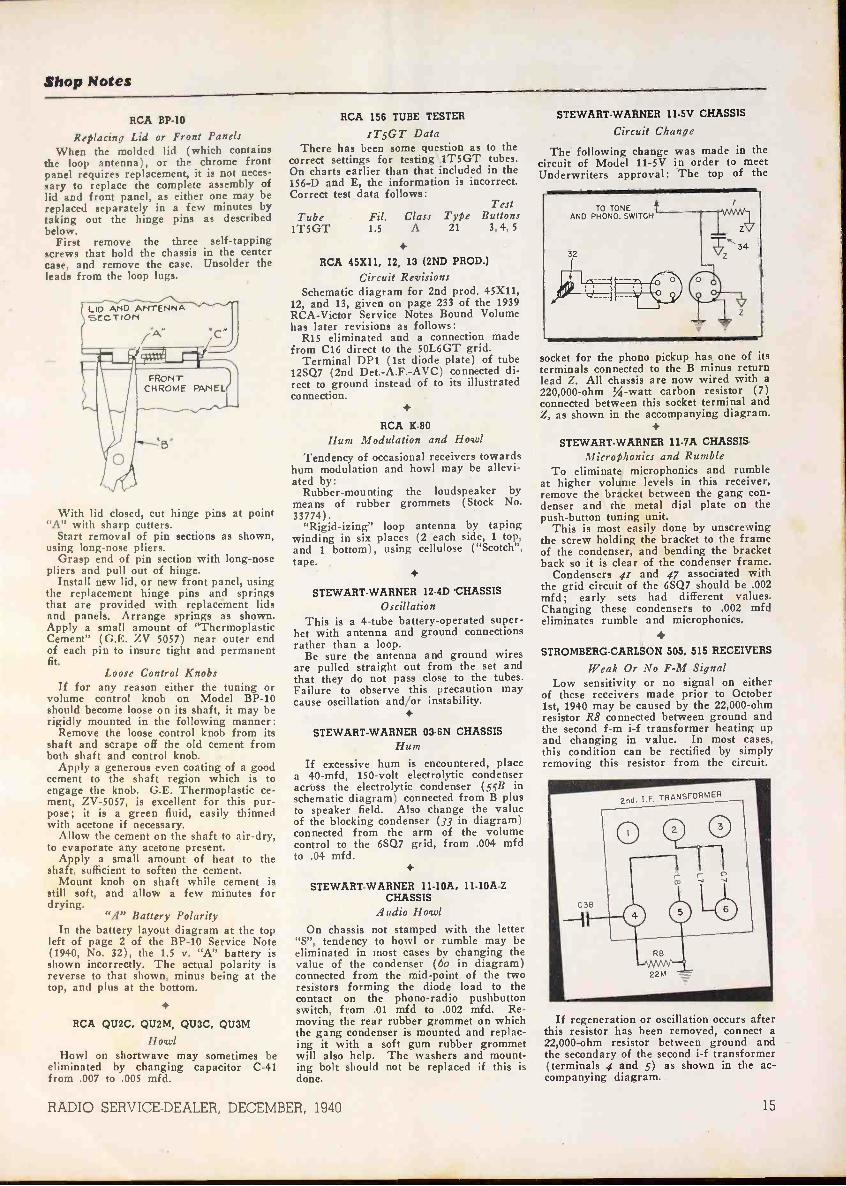
Circuit Change
The following change was made in thecircuit of Model 11-5V in order to meetUnderwriters approval: The top of the
socket for the phono pickup has one of itsterminals connected to the B minus returnlead Z. All chassis are now wired with a220,000 -ohm 4 -watt carbon resistor (7)connected between this socket terminal andZ, as shown in the accompanying diagram.
STEWART-WARNER 11-7A CHASSISMicrophonics and Rumble
To eliminate microphonics and rumbleat higher volume levels in this receiver,remove the bracket between the gang con-denser and the metal dial plate on thepush-button tuning unit.
This is most easily done by unscrewingthe screw holding the bracket to the frameof the condenser, and bending the bracketback so it is clear of the condenser frame.
Condensers 41 and 47 associated withthe grid circuit of the 6SQ7 should be .002mfd; early sets had different values.Changing these condensers to .002 mfdeliminates rumble and microphonics.
STROMBERG-CARLSON 505, 515 RECEIVERS
Weak Or No F -M SignalLow sensitivity or no signal on either
of these receivers made prior to October1st, 1940 may be caused by the 22,000 -ohmresistor R8 connected between ground andthe second f -m i-f transformer heating upand changing in value. In most cases,this condition can be rectified by simplyremoving this resistor from the circuit.
If regeneration or oscillation occurs afterthis resistor has been removed, connect a22,000 -ohm resistor between ground andthe secondary of the second i-f transformer(terminals 4 and 5) as shown in the ac-companying diagram.
15

eitcuit eou tCATHODE -ENERGIZED FILAMENT STRINGS
THE 117N7-GT, a combination rectifierand beam power tube, was developed pri-marily for use in "a -c, d -c, battery" re-ceivers where a filament string is to beoperated by the cathode current of thepower output tube. RCA ApplicationNote No. 109 deals with the perform-ance of the 117N7-GT under thesestringent conditions of operation. Basiccircuit arrangements are shown in Fig. 1,where the filament string comprises fourtubes of the 1.4 -volt line. The voltageacross the filament string is the control -grid bias for the power output unit ofthe 117N7-GT, i.e.,-5.2 volts; thisvoltage gives a design value per fila-ment of 1.3 volts when the receiver isoperated from a 117 -volt line.
The filament string for each circuit ofFig. 1 includes an 820 -ohm shunt acrossthe entire string, and a 330 -ohm shuntacross the filament of the 1H5-GT. The820 -ohm shunt is recommended when a3Q5-GT is switched into use for bat-tery operation. The 330 -ohm shunt pre-vents excessive plate current from enter-ing the 1H5-GT filament. The voltagesimpressed on the plate and screen of the117N7-GT must be such that the cath-ode current develops 5.2 volts across thefilament string when all tubes are oper-ating. This condition obtains in the cir-cuit of Fig. lA with 84 plate volts andapproximately 91 screen volts, the re-sistance of the choke being 500 ohms.These plate and screen voltages corre-spond to 96.5 volts across the secondfilter condenser.
The circuit of Fig. lA may be modi-fied to use a resistance -capacitance filter,as shown in Fig. 1B. The filament stringis the same in both circuits. For purposesof comparison, values of plate voltage,screen voltage, and filament string volt-age are shown in Fig. 2 for both cir-
cuits of Fig. 1 when the a -c line voltageis varied from 105 to 125 volts. Simi-larly, Fig. 3 shows filament string volt-age, power output, and distortion whenthe load resistance is varied. While thepower output curves show the circuit ofFig. 1B to be somewhat preferable to thecircuit of Fig. 1A, the difference inpower output is hardly enough to be animportant factor in favor of Fig. 1B.Also, both circuits were tested in atypical receiver for noise and hum. Forcircuit 1A, the noise and hum was 47db below the 600-milliwatt level used;for circuit 1B, the corresponding valuewas 44 db.
Since the performance of all tubes inthe filament string depends upon the
,-.
LINE VOLTAGE AS VARIABLE
120......'T
.......
.....,"...-
113
......
U,
n looo SCREEN VOLTAGE
Z -T/VOLTAGEwwilco
.......-.--"
.._..- -- ,
80ce
1A......-.
..--,1 1%
0wI-
tre
,_f,
?6
0-60
z ....-r-rII-w 5F -
T.......-:-....:;--1.:: FILAMENT
w ***-1ASTRING VOLTAGE
4 407.,..s
100 110 120
A.G. LINE VOLTS*- 1-
Fig. 2. Performance of 117N7-GT in thecircuits of Fig. 1, A and B.
cathode current supplied by the beampower unit of the 117N7-GT, circuitslA and 1B were compared on the basisof filament -string -voltage variations by
Fig. 1. Two arrangements for the operation of a filament string from a 117N7-GT. A plate-supply resistor of not less than 15 ohms is recommended for the rectifier unit of the
117N7-GT.
a.
cc
510
24-3 5
6
¢5
=a
43
2 .2
LOAD RESISTANCE AS VARIABLE
18
POWER OUTPUT
toFILAMENT
STRING VOLTAG
113
E
18
to TION -
00 0
LOAD
00
0
RESI STANCE = OHMS
0
0
Fig. 3. Filament string voltage, poweroutput mid distortion when the 117N7-GT
load resistance is varied.
testing a large number of 117N7-GTtubes in each circuit. The relative meritof these circuits was determined fromspot diagrams which showed the fila-ment string voltage for each of the manytubes tested. Comparison? shows that thevoltage spread \for circuit 1B is 65%greater than that for circuit 1A. Thereason for the better performance ofcircuit lA is that, in this circuit, thecombined plate and screen currents passthrough the 500 -ohm choke and, thus,cause the screen voltage to drop for ahigh -current tube and to increase for alow -current tube. Consequently, circuitlA is preferable for operating a filamentstring from a 117N7-GT.
F -M IMPROVEMENTSFREQUENCY MODULATION marches on. Ina very short space of time, numerous im-provements have been made in f -m re-ceivers.
Early tuning indicators were not sohot, since they failed to denote the pointwhere the receiver was tuned to the bal-ance frequency of the discriminator cir-cuit, which is quite a good deal differentthan the broad resonance of the i-famplifier. To obviate noise and distor-tion, an f -m receiver must be tuned tothe mid -frequency.
Both Scott and Pilot have solved thisproblem by employing any off -balancevoltage developed in the discriminator,due to mistuning, as a bucking bias.Pilot employs an additional 6H6 con-nected across the output of the discrim-inator, the cathodes of this 6H6 beingtied together. Mistuning either side ofthe mid -frequency will develop an off-balance dc voltage in the discriminatorcircuit-positive in one case, negative inthe other. In either case, this results
(Turn to page 21)
16 RADIO SERVICE -DEALER, DECEMBER, 1940
BOOK REVIEWSRider's New Meter Book . . . Books For Defense Program Students
THE METER AT WORK, by JohnF. Rider. Stiff cloth cover, 5%" by 9",152 pages, well illustrated. Published by
John F. Rider Publisher, Inc., 404
Fourth Ave., New York, N. Y.Written primarily for the serviceman
and the student, The Meter At Work isa practical handbook dealing with thetypes of meters employed in the ever-growing field of electronics. Its purposeis to acquaint the reader with the theory,design and operation of low -powermeters and their application in dailywork. To this end, the author has cov-ered the history of various types ofmeters and has used this effectively asthe basis for later discourses on moderninstruments which have their roots in theearlier designs. From there on the textflows from theory to practice, wherespecial consideration is given to theapplication of single meters to a varietyof uses.
The first chapter deals with the pur-pose of meters, types of meters, and theirbasic principles of operation. Succeedingchapters cover meters of the moving -iron, moving -coil and electrostatic types,and electrodynamometers. Characteris-tics of meters are covered in Chapter 8.Chapter 9 deals with rectifiers and ther-mocouples. Practical applications ofmeters are given considerable space inthe remaining chapter-a few of the sub-jects covered being, the choice of meters,use of shunts, extending meter ranges,construction of multipliers, checkingmeter accuracy, parallax, and generalprecautions.
This review would not be completewithout some mention of the unique andhighly effective mechanical constructionof the book itself. In the usual form oftextbook construction, if the text relat-ing to an illustration is extensive, it mayforce the location of the illustration ona page which does not face the text sothat it cannot be seen while its descrip-tion is being read. This necessitates arepeated turning back and forth of pagesso as to follow the subject matter.
In The Meter At Work this objectionis overcome by the use of split pages. Allillustrations are at the top, all readingmatter below, and each page is cut side-wise so that a text page may be turnedindependently of the page carrying theillustration to which the text refers.Hence, the illustration is always beforethe eye and conveniently just above the
text one is reading. A tape marker keepsplace for both text and illustrations.
M.L.M.
PRACTICAL RADIO COMMUNI-CATION, by Arthur R. Nilson and
J. L. Hornung. Semi -flexible binding.750 pages, well illustrated. Published by
McGraw-Hill Book Co., 330 W. 42ndSt., New York, N. Y. Price $5.00.
With so much activity in the trainingof radio operators and communicationsmaintenance men for national defense, itseems timely to review the latest editionof this book, long a favorite with thosestudying for commercial radio operator'slicenses. It is a "must" for both the in-structor and the man who intends toenter any phase of communications work.
The book is divided into four mainsections: Principles, Systems, Equipmentand Operation. Under these sections aregrouped fifteen chapters covering prac-tically every phase of commercial com-munication from both the theoreticaland practical standpoints. Of particularinterest to commercial operators will bethose chapters on transmitting circuitprinciples, control -room equipment andoperation, communication transmitters,and radio aids to navigation.
There are also included a number oftables and two appendices, one containingtechnical information and the otheroperating data. It is always a difficultproblem to combine a rigorous textbooktreatment with an operating handbookand the authors have succeeded to anextent unusual in this field of literature.Because of this fact, and because of thedetailed treatment of existing commercialapparatus; the book is to be highly recom-mended.
M.A.
RADIO OPERATING QUESTIONSAND ANSWERS, Seventh Edition,1940, by Arthur R. Nilson and J. L.Hornung. Semi -flexible binding, 415pages, well illustrated. Published byMcGraw-Hill Book Co., 330 W. 42ndSt., New York, N. Y. Price $2.50.
This book is a companion to PracticalRadio Communication, by the same au-thors, and is meant to be used in prepa-ration for the U. S. Government Ex-aminations for commercial operatinglicenses.
With the advent of a change in thegovernment examination procedure
RADIO SERVICE -DEALER, DECEMBER, 1940
(July 1939) an entirely new examina-tion technique was instituted. It was tocover these changes in examinationmethod that this edition was completelyrevised and rewritten. It provides a
quick review of essential theory, mathe-matics and diagrams for those who aretechnically familiar with the informationrequired by the government examiners.
There are 1426 questions taken ver-batim from the government examinationsand divided into six sections covering thevarious types of licenses. In addition,there are three appendices, listing operat-ing abbreviations, rules governing com-mercial radio operators, and extractsfrom radio laws.
In combination with a suitable text-book or handb ,)k, this is an invaluableaid to applic nts for the examinationdiscussed. It i to be regretted-thoughexcusable under the circumstances-thatin the effort to have the volume appearas soon as possible after the changes inregulations went into effect, a numberof typographical errors were allowedto creep into the answers. With a ref-erence book at hand however, this situa-tion would not be as serious as at first itwould seem. Hence, the work is to berecommended.
M.A.
McPROUD QUADGET AND PAD -GET. Published by Norman B. Neely,5334 Hollywood Blvd., Hollywood,Calif. Quadget, price $1.50. Padget, Price$1.25.
These two devices are ingenious ar-rangements of sliding charts intended tosimplify the design of constant -impedanceequalizers (Quadget) and attenuators(Padget) without resorting to extendedcalculations.
The Quadget determines at one set-ting the various values of inductance,capacity and resistance for any fre-quency -correcting network of either theequalizer or suppressor type. Althoughthe values are given for 500 -ohm cir-cuits, data is furnished for conversion toother impedances.
The Padget performs the same func-tion for the various types of pad attenua-tors. Those who have worked in fieldsrequiring the precise transmission andcontrol of sound at various levels andimpedances will appreciate the great dealof time which can be saved by the useof these gadgets.
17

Ptelentiny NEW PRODUCTS
RCA
Junior VoltOhymst -A push-pull elec-tronic voltmeter -ohmmeter having manyof the features of the 163 VoltOhmyst,with the addition of an isolated ac volt-meter circuit. Has complete meter over-load protection on the dc voltage and ohmscales.
The input resistance for measuring dcvoltages is constant at 11 million ohms,allowing voltages to be read in high -re-sistance circuits. On the 3 -volt scale thisprovides a meter sensitivity of 3,666,666ohms per volt. This feature permits thereading of avc, f -m discriminator, andmany other voltages which are not pos-sible with the ordinary meter. A "signaltracing" type probe lead is provided.
The dc voltmeter circuit has six ranges-0 to 3, 10, 30, 100, 300, and 1000 volts.Isolated ac voltage ranges are 0 to 10,30, 100, 300 and 1000 with a sensitivityof 1000 ohms per volt. By RCA Manu-facturing Company, Inc., Camden, N. J.RADIO SERVICE -DEALER.
BELDENH -F Cable -No. 8219 high -frequency trans-mission cable of the 100 -ohm twisted pairtype, for f.m. and television applications.Consists of 18 gauge stranded tinned cop-per, celanese braid, rubber covered, colorcoded, twisted pair with fillers, celanesewrap, tinned copper shield, cotton wrap,and rubber sheath, with outer diameter of.350".
No. 8218 cable is similar but does nothave the outer shield. Outer diameter is.270". By Belden Manufacturing Co., 4689W. Van Buren St., Chicago, Ill. RADIOSERVICE -DEALER.
WALSCO
Staple Driver-For all types of line instal-lations. Sets the staple in place by astroke or two of the palm of the hand atthe end of the driver. The head is soformed that it enables neat staplingaround corners, moldings, behind radiators,etc. Possible to install wires on mortar orplaster walls. Speeds up work 50 percent.
The Staple Driver holds strips of 24staples. Takes only four seconds to reload.Staples come in three colors-ivory, brown
and blue, for wires or cables up to 1/4"in diameter. By Walter L. Schott Co.,5264 W. Pico Blvd., Los Angeles, Calif.RADIO SERVICE -DEALER.
SPRAGUE
Multi -Section Filter-The LF-2, a plug-inmulti -section inductance and capacity filterfor use on very troublesome sources ofradio interference. Designed for installa-tion at the power outlet to which theinterfering device is connected.
The filter is designed for use on 115 -volt, ac or dc lines only, for any elec-trical device drawing up to 1/2 ampere.Measures 21/2" x 13/.1." x 1-7/16". Ground
connection provided. By Sprague Prod-ucts Co., North Adams, Mass. RADIOSERVICE -DEALER.
PRECISION
Tube Tester-Series 914 mutual conduct-ance type tube tester and set analyzer,featuring 7 -inch swivel mounted meter
providing full -view test results from allpositions. By Precision Apparatus Co., 647Kent Ave., Brooklyn, N. Y. RADIO SERVICE -DEALER.
PHILCO
Test Stand -A Test Equipment Stand toimprove the appearance and efficiency ofradio repair benches at low cost.
Sturdily built of heavy gauge sheetmetal and finished in blue enamel, thestands are so designed that any numberof them can be bolted together to accom-
modate additional test instruments. Equip-ment can be removed instantly for useelsewhere. By Philco Radio & TelevisionCorp., Philadelphia, Penna. RADIO SERVICE -DEALER.
ELECTRO PRODUCTS
A -B Power Unit -Model AD, converts port-able and home battery sets into all -electricreceivers. Will operate any 1V2 -volt radiohaving 4, 5 or 6 tubes from a 105-125 volt,50-60 cycle line, or 110-120 volt d -c line.
Provides 1.4 volts A power, and 90 voltsB power at 18 ma. Measures 61A" x 534"x 2-"'A," and fits battery space in most port-ables. By Electro Products Laboratories,549 W. Randolph St., Chicago, Ill. RADIOSERVICE -DEALER.
18 RADIO SERVICE -DEALER, DECEMBER, 1940

SELLING SERVICE(From page 7)
up the good work and try to do better.If you are getting less business than"average" you should immediatelyanalyze the reasons for your failure tokeep up with the average. And, havingfound the cause or causes, get off yourfanny and do something about it. Re-gardless of your status, see your partsjobbers at once and try to line them upso they will immediately institute a
policy of recognition and discounts tolegitimate service -dealers only. That isthe first and basic step to take and itpaves the way for the sound, aggressiveprocedures which must follow.
Step two is obvious. Study your rec-ords and the potential market which sur-rounds you. For example: In a practicalmanner, figure for yourself just howmany sets are in operation within yourbusiness area. How many of these"neighbors" are your steady customers?How many of their sets did you servicethese last three months? How manytubes are in all these sets . . . and howmany of these tubes are two or threeyears old? Theoretically, how many areweak? How many replacement tubesdid you sell during the past threemonths? Analyze, man, and you'llquickly realize that even if you are "anaverage service -dealer getting an aver-age share of business" you did not sellanywhere near the total replacementtube volume that you should have.Again we say-study your business andcompare it with what you should getand can get if you will but go aboutthings in a practical, aggressive manner.
In this regard RADIO SERVICE DEALERwill afford vast cooperation in a mannernever before attempted by a radio pub-lication. RSD will give you plenty ofammunition to shoot with-but it isyour job to load your gun, take aim andfire. More important, you must keepaiming at the goal, which is More Busi-ness and More Profits, and you mustkeep firing. If you follow RSD's planconscientiously, you cannot miss.
APPLY FOR CERTIFICATION SEAL
First thing to do is simple. Apply toRADIO SERVICE DEALER for recognitionas a "Certified Service -Dealer." Stateyour qualifications and obtain, if youmeet the rigid requirements, one of thedistinctive, four-color Decalcomaniaswhich will, when applied in a prominentspot on your store window, distinguishyou in your community and afford a basisupon which an aggressive campaign forincreasing business can be made. Re-member, these seals are available withoutcharge to any independent serviceman,servicing organization, or dealer who
maintains a service department-sub-scribers and non -subscribers alike-pro-viding the rigid requirements are met.
When your Seal or Certification isdelivered and affixed to your window getbusy. Make a direct mail campaignannouncement to every customer now onyour books and to a list of potential cus-tomers who reside within reasonablelimits of your establishment. By meansof photo offset printing, 500 letters canbe printed in a dignified manner on nicestock for less than $3.00. Envelopes costabout $2.00 printed. Postage amounts to$10.00, so the 500 initial announcementswill cost approximately $15.00. One
thousand announcements would costapproximately $25. It hardly pays to
print less than 500 at a time, the onlysaving involved in a smaller mailing be-ing the postage, which is the biggest itemin every case. Boys, if they can be reliedupon, will probably be able to distributeyour literature under doors, and in postboxes for less than the cost of postage.In many communities this direct deliverymethod violates city or local ordinances,so, before using it ask your local authori-ties and act accordingly.
Another advertising medium which"Certified Service -Dealers" should notneglect is the Telephone Company Classi-
MODEL 589 TUBE AND BATTERY tester has acompletely modernized circuit. The tube testsockets are not wired directly to the circuit, but,instead, pass through the patented SUPREMEDouble Floating Filament Return Selector sys-tem which automatically re -connects all tube ele-ments to any possible tube base arrangement.Due to the fact that any or all elements of eachsocket can be rotated to any desired position,only one socket of each type is necessary. Testsevery type of tube from 1.4 volts to fyll line volt-age at its correct anode potential under properload. Tests separate sections in multi -purposetubes. Checks all leakages, shorts, open elementsand filament continuity with a neon lamp. A cir-cuit insert -is provided for checking noise, leak-age, loose and had connections.The battery testing circuit of the Model 589 pro-vides the proper load at which each battery is tooperate, plainly marked on the panel, for all 1.5,4.5, 6.0, 45 and 90 volt portable radio types. The
'condition of the battery is indicated on an Eng-lish reading scale.This is the fastest and easiest tester to operate.
Just "follow thearrows"-you can'tgo wrong. Rollertype tube chartwith brass gearedmechanism liststubes in logical nu-merical order. Eachtester carries a oneyear free tube set-ting service. SU-PREME engineer-ing and construc-tion PLUS the bestmaterials the mar-ket affords, makethe 589 your big-gest dollar value.You will be proudto own this instru-ment.
Terms: $4.00 cad'and 8 monthlypayments of $3.63
FR EETUBE SETTING
SERVICEFOR ONE YEAR
IN producing Model589 there has been
no compromise in thecircuit design or ma-terials. The samemanufacturing meth-ods, careful inspec-tion and accurate cal.ibration are incorpor-ated in this instru-ment as in all otherSUPREME testers. Itwill pay you to Inves-tigate and see thistester before youbuy. Its price is thelowest at which aGOOD tube testercan be built.
MODEL 599 TUBE AND SET TESTER Is verysimilar in appearance to the Model 589, and in-cludes all the features and advantages of thisinstrument. In addition, it provides the followingranges:0.2 TO 1500 D.C. VOLTS -5 carefully selectedranges -0/6/15/150/600/1500 volts. 1000 ohms pervolt STANDARD sensitivity.0.2 TO 600 A.C. VOLTS -4 A.C. ranges -0/6/15/150/600 volts. Rectifier guaranteed with instru-ment and fully protected from overload damages.0.2 M.A. TO 600 91.A.-3 direct current ranges0/6/60/600 allow measurement of screen, plate,"B" supply and D.C. filament loads.0.2 TO 600 OUTPUT VOLTS -0/6/15/150/600 ---ideal for alignment. No button to hold down-noexternal condenser necessary.0.1 OHM TO 20 MEGOHMS-4 ranges 0/200/20,000ohms, 0/2/20 megohms. A low range at high cur-rent with 3.5 ohms center scale.ELECTROSTATIC-ELECTROLYTIC LEAKAGETEST-Sensitive calibrated 20 megohm rangeprovides excellent leakage test of paper and elec-trolytic condensers.Just as the 589 isyour best value in.a tube and batterytester, the 599 isyour best value ina combination tubetester, battery test-er and set tester.Remember, youhave all the fea-tures of the 589PLUS a completeAC. DC volt, ohm.megohm, milliam-meter. at a cost ofonly 47c per range.Dealer Net Cash Price
$39.50Terms: $4.50 cash;9 payments of $4.33.
Illustrated above is the Model589 in a counter type metal case.This model is available with op-tion of 7" or 9" illuminatedmeters. Has two neon lamps forsensitive or super -sensitive tests.Write for prices and Information.
V
SUPREME INSTRUMENTS COMP.GREENWOOD. MISSISSIPPI. U. S. A.
New Catalog Just Off Press.Write for your copy Today:
Metal cabinets as illustrated forthe Model 589 at lett and 599above are identical-can be usedeither in a horizontal position orvertical position by merely re-versing the inttrument panel.Write for prices and information.
RADIO SERVICE -DEALER, DECEMBER, 1940 19
Presenting the1941
Meissner
ANALYSTIncorporating a New, Direct -Reading
ELECTRONIC VOLTMETER
Save Time-Save Money-Handle servicejobs faster with the assurance that they will"stay sold"! Almost Magical in its uncannyability to ferret out obscure faults and laythem open for your inspection, the New Meiss-ner ANALYST handles the receivers of yes-terday, today and tomorrow-with equalefficiency and facility. Entirely fundamentalin its testing procedure, it is one piece ofequipment that will never become obsolete !
The New Meissner ANALYST locates faultsby the "Signal Tracing" method-proven tobe the fastest and most reliable. Five separateand distinct "channels" provide as many dif-ferent functions, each in its own panel divisionwith all controls accurately calibrated. Fur-nished with tubes and instructions, complete-ready to go to work!
No. 9-1040 New ANALYST $87.50Complete with Tubes, Net .. .
Limited Quantity of 1940 ModelsAvailable at Reduced Price!
The same ANALYST that sold in kit form at$100 list-now offered completely wired, withfull set of 13 tubes-ready to operate! Simi-lar to the New ANALYST described aboveexcept has electron -ray indicator instead ofmeter for DC measurements.
No. 9-1025 Net Price . . . $69.50Write for Free 1941 General Catalog
"PRECISION -BUILT PRODUCTS"
Servicemen-the un-sung heroes ofradio, said TomJoyce, RCA VictorVice President, at arecent round -tablediscussion broadcastover WFIL, underthe auspices of ThePhiladelphia RadioServicemen's Asso-ciation. Mr. Joyce(third from left)brought along Dr.Morton, G. L. Beersand Dr. Olson,prominent RCA en-
gineers.
ified Business Directory. Be sure, im-mediately after receiving your Seal, thatyou order your local phone company'sbusiness office to change your copy ifyou are a display space user. Your busi-ness cards and letterheads should alsohave the CSD Seal imprinted. Electro-types of the distinctive "Certified Service -Dealer" insignia are available in severalsizes and at reasonable prices. Furtherinformation, prices, etc. will be sent onrequest to RADIO SERVICE -DEALER.
CONTACT CUSTOMERS
Personal calls are unquestionably themost effective means of consummating a
Once your Certification Seal hasbeen awarded, plan your workingschedule to provide at least 2 hours dailyfor calls on old customers whom youhave' not seen or done business with inseveral months. Study your files. Prob-ably nine out of every ten customers onyour books fall into this category. You'dbe surprised how time flies and repeatbusiness fails to materialize because oflost contact.
In planning a series of unsolicited.home calls, do not work on a hit-or-missbasis. Study your daily drop-off or pick-up and group your intended calls for thatday to fit adjacent neighborhoods. It isa perfectly accepted and not offensivepractice to ring an old customer's doorbell with the explanation, "I had to in-stall a set at Mrs. So-and-So's aroundthe corner and didn't want to pass byyour house without checking up on thereceiver I fixed up for you recently. It'sa part of our routine service" . . . andso on! Remember, you are not out onsocial visits. Your primary purpose isto get an order. To do this you mustget into the home, inspect the set or setsand try, if possible through casual con-versation to ascertain whether or not anyof your customer's friends or neighborsare in the market for a radio service-man's services.
Keep in mind the axiom, "The earn-ing capacity of a radio service -dealer de-pends upon his selling ability." If youdon't see people you cannot sell them.
Whether you sell a bill of goods or afavorable impression makes no difference.Ultimately, both will result in yourmaking a bank deposit.
SERVICEMAN'S DIARY(From page io)
when your son started, his voice soundedjust as bad as . . ."
That was enough for me. I slippedout into the hall and got my coat onagain. Then I noticed the girl hadfollowed me.
"Don't be angry," she murmured. "Ilike your voice. The teacher did, too.That's why he wanted Jerry, whose voiceis so rough. But, you see, you were somad that you growled. And your voicedidn't sound so good, then. And myname's Mary . . ."
Mary had a little lamb. Now Maryhas a radioman.
STEREOPHONICS(From page 5)
for the cardioid pattern and so tilted(Fig. 3) that its pickup was confinedmostly to the front of the stage center.Since this microphone was closer to theartists than the side microphones, the116A amplifiers associated with it wereoperated at a lower level than those ofthe side microphones. In this way, avery satisfactory auditory perspectivewas obtained with only two channels.
Immediately before each of the foursessions, the operators balanced the am-plifiers as previously described and tooka quick overall frequency run using thedummy resistance load. A minimum ofmonitoring was done during the programsince the aim was to reproduce the pro-gram as faithfully as possible. In gen-eral the only adjustments made werea slight increase in level of the centermicrophone during solos. There was noneed to compress the volume range, dueto the excess output capacity availableand the low noise level of the system.
20 RADIO SERVICE -DEALER, DECEMBER, 1940

EFFECT ON AUDIENCE
One of the best indices of the audienceresponse to the installation was theattendance at each of the four sessions.No particular advance publicity had beengiven out regarding the installation sinceit was felt that the public should beallowed to form their own opinions. Asa result, the attendance at the firstsession was poor. It was noticed, how-ever, that the same people returned forthe succeeding sessions and in each casebrought friends with them. At the lastsession the auditorium was completelyfilled. At the end of each session themost favorable comments were heard.Many of these comments were particu-larly interesting. Everyone seemed toagree that after the first few minutesthey were completely under the illusionof the choir and orchestra being hiddenbehind the curtain at the front of theauditorium. Those familiar with repro-ducing systems attributed this to the
' faithfulness of the reproduction with noaudible distortion as well as to thestereophonic effect.
The behavior of the audience duringthe programs served as another index ofthe success of the installation. Completeabsorption in the music was apparent.The slightest disturbing movement on thepart of anyone drew silencing looks fromhis neighbors. Many followed the musicnote by note from open scores. Duringthe magnificent crescendos in the BMinor Mass the audience would sit upalmost breathless and when the musicsuddenly dropped to the barest whisper,one could hear audible sighs. This re-sponse of the audience was particularlystriking in view of the altogether toocommon habit today of carrying on aconversation during any reproducedprogram.
F -M IMPROVEMENTS(From page 16)
in a positive voltage on the paralleledcathodes of the additional 6H6. Thispositive voltage is employed to offset ,thenegative voltage developed in the gridcircuit of the limiter and which is used toactuate the tuning eye. Hence, the tuningeye remains open until the balance fre-quency is reached, at which time a po-tential difference no longer exists in thediscriminator circuit. Therefore, novoltage is developed on the cathodes ofthe additional 6H6, the negative limitervoltage is released and closes the eye.
Both Scott and General Electric em-ploy cascade limiters as a means offurther reducing noise interference. Thefirst limiter does the real dirty work, re-ducing the noise amplitudes to smallvalues. The second limiter takes upwhere the first limiter left off, polishingoff what remains in the way of noisepulses.
The new General Electric F -MTranslator Model JFM-90 is a doublesuperhet, with two converters insteadof one converter and one r -f stage. In-creased sensitivity is gained with thisarrangement because the first converterreduces the signal frequency to abouthalf its value with the result that thesecond converter tube can get in somereal gain in front of the i-f amplifier.In effect, the conversion transconduct-ance of the circuit is considerably in-creased.
RADIOLA 510
(From page 6)
ceiver dial pointer full clockwise and ad-just the oscillator trimmer C3 for maxi-mum output.
Step 4. Tune test oscillator to 1400kc, tune receiver to oscillator frequencyand adjust the antenna trimmer Cl formaximum output.
LEAD DRESS
Dress grid lead of 12SK7 close tochassis under condenser C12. Dressgreen and blue leads from i-f trans-formers close to chassis and away fromeach other. Dress leads from terminalboard on loop support away from loop.
BATS OVER BATTERIES
Dere Mr. Editor:On account of a peculya series of events,
maybe you'd better change my address onyour records. Thair is some talk goin'round that our street, up to now called"Washington Street" is gonna be re -named"Wanderer's Row"-and I, for one, thinkit's only right to do so. Either that or
Eureka!He's done it again!
Homer G. Snoopshaw,B.R.S. (BatteryReplace-ment Specialist), once more comes through in hiscapacity as Replacement Adviser in Bud's Radio Shop.
After studying this troublesome mail-order DynamicDeLuxe for only four days, he is able to state emphat-ically that the correct battery for this portable is BurgessNo. IGA42_ A call to theburgess Distributor and thecustomer is satisfied and onhis way.
How could Homeesemployerpossibly get along withouthim?*
Gift YourselfRADIO SERVICE -DEALER
For Christmas
JOBBERSwrite for details ofnew, profit - makingmerchandising plan.
presents . . .
"COMPANIONETTE 17
a money-making 4 pounderideal for service -dealers
These gorgeous streamlined 4 tube, 4 lb. miniature batteryportables are "naturals" for Service -Dealers. Display them inwindows, on counters-carry them on service calls. THEYSELL QUICKLY-afford a neat profit on a small investmentand build steady replacement battery business. Model 410illustrated LIST PRICE $19.95 complete with batteries.
* FEATURES: 4 tube superhet; powerful P.M. dy-namic speaker; Aye; iron core High Gain I -F trans-former; self-contained Looptenna. 2 flash light cells"A" supply last 15 hours, "B" battery 50 hours.Case of simulated cow hide with saddle stitching. 'Range 170 to 555 meters.
DEWALD RADIO MFG. CORP.440 LAFAYETTE STREET NEW YORK, N. Y.
RADIO SERVICE -DEALER, DECEMBER, 1940 21
new
JI
n*Webster defines "new" as: "Lately
made. Lately discovered. Renewed.Different." All of these descriptionsapply to the Rider Books listed be-low. They have all been recentlypublished. They all bear on latelydiscovered developments or cur-rently revived subjects-and theyare all different-in approach, han-dling and even in physical make-up. Order the ones you need-TODAY.
new*MA"Z BOOK
Embodies a new fea-ture exclusive to RiderBooks. Pages are splitso that the upper parts(containing diagramsand charts) can beturned without dis-turbing the lower partsof the pages (contain-ing text.) Obvious ad-vantage in the readingand study of "Metersat Work." Only $1.25.
OUT DEC. 18th-ORDER YOURS TODAY
newSERVICINGTECHNIQUE
Servicing by SignalTracing is being usedby an ever increasingnumber of professionalradio servicemen forlocating troubles inevery conceivable typeof radio communica-tion system. It is themost fundamentalmethod - free fromevery limiting factorheretofore encoun-tered. 360 pages -188illus.-$2.00
newDEVELOPMENT
Frequency Modula-tion is not just a com-ing thing-it is here!This book explainstransmission and re-ception of F -M signals-discusses the newF -M sets136 pages-Illustrated-$1.00
EXPLANATIONOF THEORY
Know all about Oscil-lators. Get your mon-ey's worth out ofthem. Know how totest them - repairthem. Protect the in-vestment you have inoscillator equipmentand make any futureinvestment in the light
of the knowledge this book gives you.256, pages -167 illus.-$1.50
p
JOHN F. RIDER PUBLISHER, INC.404 Fourth Avenue, New York City
Export Division: Rocke-International Elec. Corp.,100 Varick St., New York City. Cable: ARLAB
Read RIDER BOOKS
"Portable Promenade." You see, it's all onaccount of these here portable radios andbatteries. Me and Elmer Spangler-heruns the "Nev-r-Sleep Radio Shop"-well,we were talking to Tom Howard, down athis place-"Howard's Radio Hospital,"and we all three says it's really something.You see, when we first started sellingportables a couple years ago, we sold quitea few and made money on 'em-& on bat-teries, too. I sold the Consolidated line,Tom had Argonaut, and Elmer was sellingDynamics. We made money and got alongtogether fine. Then all of a sudden Argo-naut brought out a AC -DC set, using a 6 -volt "A" Battery, and at the same time,Consolidated put out a 4% -volt -90 -voltpack for their new set. Then Dynamicdecided to use a smaller 1% -volt "A" anda special 60 -volt "B" and also a longstrung out style 7% -volt "A". This wasrather confusing and I had to add a extryshelf for battery stock. Then Tom got ina set that used a 88% -volt "B" and 7flashlight batteries-and my new line re-quired a 4 -prong 6 -volt "A", a 8 -prongpack, a 71/2 -volt "A", a 30 -volt "B" and anew shape 1% -volt "A". I cut off half myservice bench and shifted my equipmentaround & made room for the new batteries.Then a tourist one day brought in a setthat couldn't have used any battery I eversaw. As near as I could dope it out it hadoriginally been equipped with a weak 6 -volt "A", a telephone dry cell, a penlightcell, a heavy-duty B&C pack and a coupleof double -edge razor blades. The ownerof this remarkable set sed it was won ona punch board last summer. After look-ing quite a while, I was surprised to findConsolidateds name plate on it. I wrotethem and after some correspondence foundthat they were sorry, but that set was adiscontinued model-a early fore -runner oftheir famous "Play Day" model. Thismade the party quite angry and he junkedhis set-hard-on the sidewalk.
I tried telling my customers to stick toreasonable style batteries, but you knowhow some of 'em are. Why, I know onefella here in town has 3 portables, all ingood condition, but cant get batteries for'em for love nor money. Well, to makea long story short, you wouldnt reckoniseour street now, the sidewalks are alwaysfull of folks carrying portables in and outof radio shops. It looks like we're busy,and we are-busy telling folks we're "freshout of 11 -prong 9 -volt 75 -volt packs-tryTom, he had some last week."
"Wanderer's Row"-that sounds allrightto me. Or maybe we should call it "Bat-tery Park" seein how many of those screwybatteries park on our shelves. Anyway,youre gonna hafta change my address be-fore long-and maybe it will be care ofthe county home (or the asylum).
By the way, is thair any truth in therumor that the reason Consolidated wentbusted is because Mr. Consolidated wentnuts trying to figure out a new tube andbattery hook-up? I heard so.
Well so long till later. Your old bud,Puzzled Pete
APPOINTMENTSRCA-Dobbs-Fred Dobbs, well knownthroughout Texas and the Southwest as aTube and Parts salesman attached to theRCA Manufacturing Company's Dallasdistrict office, has been transferred to theNew York RCA office to take over simi-lar duties there.
Mr. Dobb's duties in Dallas have beenassumed by II. B. Chapman, formerly ofthe RCA field engineer force in Texas.
Subscribe Now To
RADIO SERVICE -DEALER
while the dollar -savingV2 Regular Price
SUBSCRIPTION RATE
-12 Issues for $1.00-is still in effect
(Use the coupon on page 3)
Reach for aDANDEE!
If ever there was a condenser that couldqualify as a so-called universal or general -utility replacement, it's the new PRS 450-8Aerovox Dandee. It's the most compactmidget metal -can dry electrolytic on themarket . . . a genuine hermetically -sealedjob properly vented . . . full -rated capacityand voltage . . . colored polarity -indicatingends . . . spun -over jacket preventing shortsand grounds-in a word, a real good elec-trolytic.And now, for your convenience, these PRS450-8 Dandees come packed five to the box.Buy a box. Pack it in your old kit bag.And when it comes to those quick servicingjobs, just reach for a Dandee! Also packedindividually.Ask Your Jobber ... Ask for a carton of Dan-dees. Always have a box on hand. Also ask forlatest catalog on condensers. Or write us direct.
EROvoxCORPORATI.044
NEW. BEDFORD,'t.
22 RADIO SERVICE -DEALER, DECEMBER, 1940
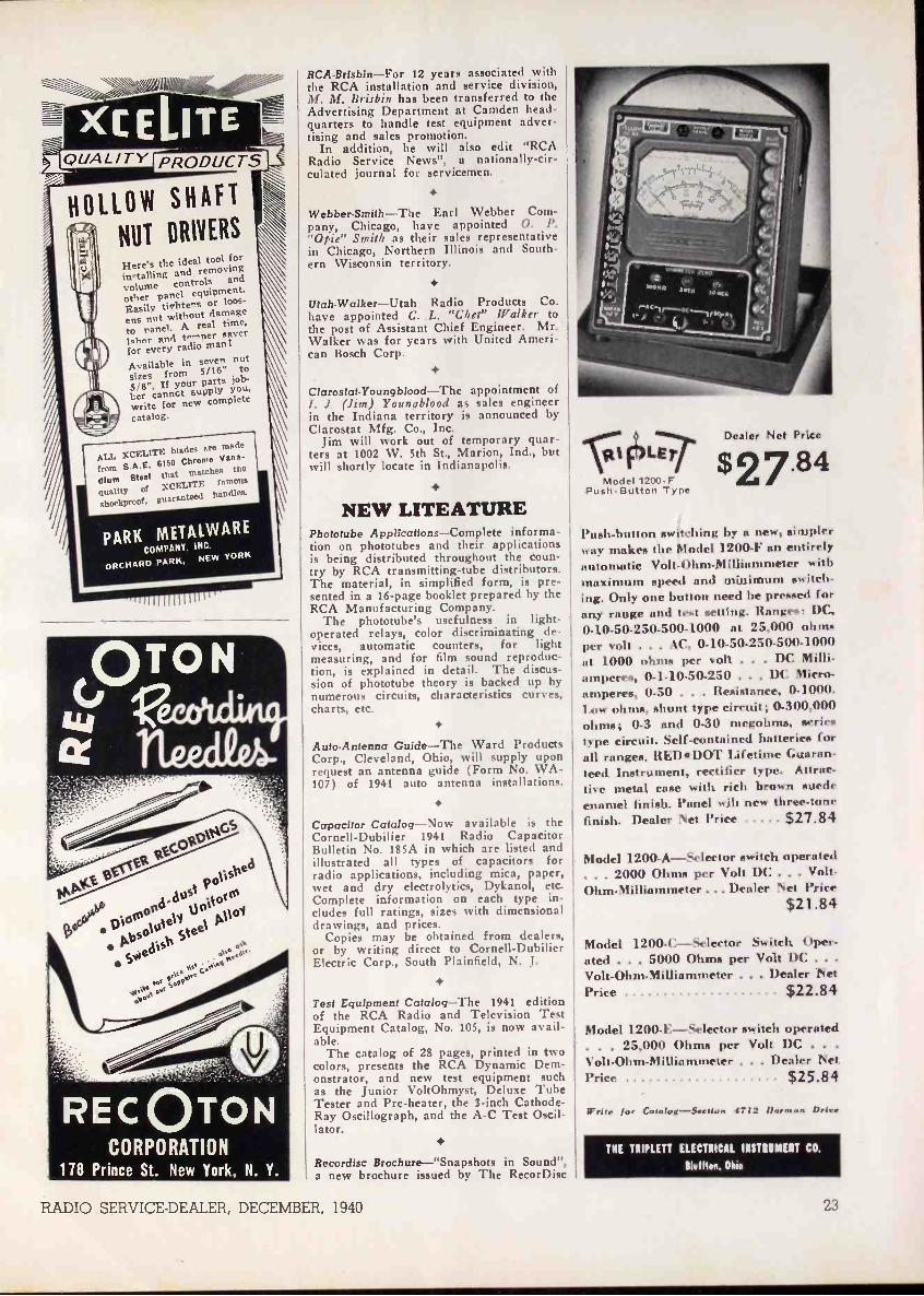
,11
XCELITEQUALITY PRODUCT:sir
HOLLOW SHAFT
NUT DRIVERS
e's the ideal tool forin<talling and removing
volume controls and
other panel equipment.Easily tivhtens or loos-
ens nut without damageto ranel. A real tune,
nr awl t.:<oer <aver
for every rad.o man!
I
vailable in seven nut
sizes from 5/16" to5/8". If your parts yjob-
ber cannct suPP-iVwrite for new completecatalog.
A
ALL XCELITEblades are made
from S.A.E. 6150 Chrome Vana-
dium Steel that matches the
Quality of XCF.L1TEfamous
shockproof, guaranteed handles.
PARK METALWARECOMPANY. INC.
ORCHARD PARK,NEW YORK
RCA-Brisbin-For 12 years associated withthe RCA installation and service division,M. M. Brisbin has been transferred to theAdvertising Department at Camden head-quarters to handle test equipment adver-tising and sales promotion.
In addition, he will also edit "RCARadio Service News", a nationally -cir-culated journal for servicemen.
Webber-Smith-The Earl Webber Com-pany, Chicago, have appointed 0. P."Opie" Smith as their sales representativein Chicago, Northern Illinois and South-ern Wisconsin territory.
Utah-Walker-Utah Radio Products Co.have appointed C. L. "Chet" Walker tothe post of Assistant Chief Engineer. Mr.Walker was for years with United Ameri-can Bosch Corp.
Clarostat-Youngblood-The appointment ofI. J. (Jim) Youngblood as sales engineerin the Indiana territory is announced byClarostat Mfg. Co., Inc.
Jim will work out of temporary quar-ters at 1002 W. 5th St., Marion, Ind., butwill shortly locate in Indianapolis.
NEW LITEATUREPhototube Applications-Complete informa-tion on phototubes and their applicationsis being distributed throughout the coun-try by RCA transmitting -tube distributors.The material, in simplified form, is pre-sented in a 16 -page booklet prepared by theRCA Manufacturing Company.
The phototube's usefulness in light -operated relays, color discriminating de-vices, automatic counters, for lightmeasuring, and for film sound reproduc-tion, is explained in detail. The discus-sion of phototube theory is backed up bynumerous circuits, characteristics curves,charts, etc.
Auto -Antenna Guide-The Ward ProductsCorp., Cleveland, Ohio, will supply uponrequest an antenna guide (Form No. WA -107) of 1941 auto antenna installations.
Capacitor Catalog-Now available is theCornell-Dubilier 1941 Radio CapacitorBulletin No. 185A in which are listed andillustrated all types of capacitors forradio applications, including mica, paper,wet and dry electrolytics, Dykanol, etc.Complete information on each type in-cludes full ratings, sizes with dimensionaldrawings, and prices.
Copies may be obtained from dealers,or by writing direct to Cornell-DubilierElectric Corp., South Plainfield, N. J.
Test Equipment Catalog-The 1941 editionof the RCA Radio and Television TestEquipment Catalog, No. 105, is now avail-able.
The catalog of 28 pages, printed in twocolors, presents the RCA Dynamic Dem-onstrator, and new test equipment suchas the Junior VoltOhmyst, Deluxe TubeTester and Pre -heater, the 3 -inch Cathode -Ray Oscillograph, and the A -C Test Oscil-lator.
Recordisc Brochure-"Snapshots in Sound",a new brochure issued by The RecorDiec
RADIO SERVICE -DEALER, DECEMBER, 1940
.1\117:1 LErModel 1200P
Push -Button Type
Dealer Nut Price
$27.84
Push-button sw by a new, -implerway makes the Model 1200-F nn entire!,automatic Volt-Ohm-Milliammeter withmaximum speed and minimum «witch-ing. Only one button need be pre««ed forany range and test setting. flanges: DC.0-10-50-250-500-1000 at 25,000 ohm«per volt . . . AC, 0-10-50-250-500-1000at 1000 ohms per volt . . . DC Milli-amperes, 0.1-10-50-250 . . . DC Micro-amperes, 0-50 . . . Resistance, 0-1000.Low ohms, shunt type circuit; 0.300,000ohms; 0-3 and 0-30 megohms, seriestype circuit. Self-contained batteries forall ranges. REDDOT Lifetime Guaran-teed Instrument, rectifier type. Attrac-tive metal case with rich brown suedeenamel finish. Panel wih new tilt -cc -tonefinish. Dealer Net Price $27.84
Model 1200-A-Selector switch operated. . . 2000 Ohms per Volt DC . . . Volt-Ohm-Milliammeter ... Dealer Net Price
$21.84
Model 1200-C-Selector Switch Oper-ated . . . 5000 Ohms per Volt DC . . .
Volt-Ohm-Milliammeter . . . Dealer Net
Price $22.84
Model 1200-E-Selector switch operated. . . 25,000 Ohms per Volt DC . . .
Volt-Ohm-Milliammeter . . . Dealer NetPrice $25.84
Writs for Catalog-,Soctiow 4712 Marrows Price
THE TRIPLETT ELECTRICAL INSTRUMENT CO.
Bluffton, Ohio
23
iN EW 1941PROFIT GUIDE
1414441-,RADIO!
41.qi
i0
..........,...riAto___.....3_,.,>......-,t.:.-
2111'!......ss Illizt,'..,.2!,........filill17,1111'.....
Complete Selections . . . Guaranteed Quality
Replacement PartsEverything you need in exact dupli-cate or universal replacement orrepair parts. Tubes, condensers, re-sistors, transformers, hardware,tools, etc. Leading brands.
Latest Radio SetsA model for every purse and purpose.Auto Sets. Midgets, Battery Por-tables, Table Models, Consoles,Phono-Radio and recorder combina-tions-for operation on AC or DC.
Public Address EquipmentA complete line of amplifiers, micro-phones, baffles, recording equip-ment and accessories for every typeof installation-permanent, portableand mobile, from 5 to 100 watts.
Newest Electric AppliancesExtra profits for you! StandardBrand Electric Irons, Grills, Tost-ers, Percolators, Waffle Irons, Va-cum Cleaners, Clocks, Mixers andmany others, all at lowest prices.
YOU SAVE MONEY AT RADOLEK
MAIL THIS COUPON TODAYThe RADOLEK CO.601 W. Randolph St., Chicago, Dept. sll-49Send the New 1941 Radio Profit Guide FREE.NameAddress Dealer?Experimenter? Serviceman? Amateur?..
Corp., 395 Broadway, New York, N. Y.,manufacturers of home recording blanks.Literature lists 3 grades, the Semi-profes-sional, the Economical and the Amateurlines, in bothmable coatings.esting data oneluded.
Available throughrect from.RecorDisc.
nitrate and non-inflam-Also accessories. Inter -
recording practice is in -
distributors Or di -
Carron 1941 Catalog-New 60 -page catalogcovering replacement cones and voice coils,r -f and i-f coils, pickup coils, etc. Of spe-cial interest are the new Carron frequencymodulation kit and components.
Copy free on request to Carron Manu-facturing Co., 415 So. Aberdeen St., Chi-cago, Ill.
Shure Catalog-No. 153. Has 12 pages.Includes such new items as the "Strato-liner" microphones, magnetic recordinghead, etc. Shure Brothers, 225 W. HuronSt., Chicago, Ill.
Precision Catalog -New 12 -page catalogcovering the 1941 line of Precision Ap-paratus test equipment. Precision Appa-ratus Co., 647 Kent Ave., Brooklyn, N. Y.
Allied Dictionary-A Dictionary of RadioTerms, containing definitions of approxi-mately 800 radio terms and abbreviations.Also schematic symbols, tips on readingcircuit diagrams, color codes, etc.
Has 36 pages with grey and marooncover. Measures 6 by 9 inches. Copy maybe had for 10 cents from Allied RadioCorp., 833 West Jackson Blvd., Chicago,Ill.
B ACAntennae
AutomobileHome - All types
F -M SystemsTelevision
Police MarineMultiple Systems
Complete KitsAccessories
Made by World's Oldest and LargestManufacturers of Radio Aerial Systems
MFG.CORP.
55 DICKERSON STREETNEWARK, N. J.
Mr. Radio Serviceman:
RSA MEANS BUSINESS!New business promotion plans and new member -helps spell in-creased profits for RSA members at the start of the new season.Watch for the RSA Replacement Parts Guide-New BroadcastPromotions-New Member Helps! Don't be the last man to yourneighborhood to join RSA. Send the coupon Today!
mi MAIL THIS COUPON NOW!
RADIO SER
304 S. Dearborn St.,Chicago, IllinoisI am interested in RSA Membership. Tell me about it.
Name
Address
LCity State
VICEMEN OF AMERICA, INC.
RS -I240
NM OM EMIS NM MEI 1111111
1 Let's Grow Together
in 1940!
I RADIO SERVICEMENOF AMERICA, Inc.Reliable
JOE MARTY, JR., EXECU304 S. DEARBORN STREET, CHICAG
Service AssuredIVE SECRETARY
U.S.A.N
24 RADIO SERVICE -DEALER, DECEMBER, 1940
vogesk
vleskkve ° Axe
evs
stol sceo-ss
140v1a,yvodv,ces
speaVta-ad
VoNitilks
okcA
tlyeskol
eel\OW),
ok so,PdVaskaN1a
t:Ida.l't i$ kVe
c.11.11
COraplete
VasaOade.
Nsklovs
\otioet
kota 1Neg
cetcsNo4
ot NrIvIkeOA-
teckko
Abe00:va
okk:Nce
ItNI014
lov\t.
eva cowsc'okcil"
MARINE HORN SPEAKERSRe-entrant typespeakers usinghorn type unitsfor marine andgeneral P -A ap-plications - maybe used as loud-speaker or as amicrophone.Miniature a n dregular sizes ap-proved by t h e
Bureau of Marine Inspection andNavigation, Department of Com-
merce, for marine work. In all sizes, minia-ture, midget, regular and hull, handling from5 to 50 watts.
Super
GiantP. M.
Horn Unit
Operatingcapacity 12-15 watts,
peak 25 watts. Other P.M.units available, from "babyunit" of 5 watts to "bull unit"with an operating capacity of 50watts. Efficiencies of the high-est order obtainable with thefinest magnetic material andsteel utilized.
There are several types of horns, speakers andtrumpetsRACONS.such as
on the market which resemble genuineRACON's patented, exclusive features
stormproof, weatherproof acoustic ma-terial and our line of unbreakable horns cannot beduplicated. Also, every RACON speaker deliversmaximum output and response obtainable for thesize of driving unit used. From coast to coast andon the seas RACONS are specified by leading sound -men for better, more dependable and profitablesound installations because the Racon Elec. Co. isa nation-wide organization, with nation-wide dis-tribution and a world-wide reputation.
101111m.c_______ILD- - -PAGING HORN
A small, extremely efficient 2 -foot trumpet speaker, for usewhere highly concentratedsound is required to overridehigh noise levels, such as infactories, outdoors, etc. Usesa small, very efficient Perma-nent Magnet unit. Particu-larly adaptable for paging sys-tems, hotel lobbies, trucks, etc.
Ra-EntrantTrumpets
A compacttrumpet ot h e doublere-entranttype. Occu-pies but asmall space,n everthelesshas a longair columnenabling itto deliverhighly concentrated sound of the greatestefficiency over long distances. Base and insidecone arm made of aluminum castings, outsidebell of heavy gauge aluminum spinning, cen-ter section of BACON ACOUSTIC materialto prevent resonant effects. Available In 6',41/2', 3Y.', and 1' air column units.
RACON ELECTRIC CO. 52 EAST 19th ST. NEW YORK, N. Y.

COMPLETEStock No. 165
)0 0,
HAVE you been stymied on toughjobs because you couldn't measure
voltages without loading the circuit?Now the kind of instrument you've al-ways wanted-a D. C. Electronic Push -PullVolt-Ohmmeter-is priced scarcelyhigher than an ordinary volt -ohmmeter!
Now you can check oscillator voltagesat the grid of the tube, with the signalpresent... with the circuit functioning! Read-AVC, AFC and FM discriminator voltages...check bias -cells without harmful drain...D. C. voltages in high -resistance photo-cell circuits ... television circuits! See howmuch time you can save on both routineand special jobs, with a meter that offersa constant input resistance of 11,000,000ohms-sensitivity as high as 3,666,666ohms per volt!
And the Ohmmeter side of the Volt-Ohmyst story! 0.1 Ohms to 1,000 Megohms
COMMON
Resistance -Readings! No leads to short-no zero -point resetting as you switch infive steps over the ranges that let you readaccurately resistance from 0.1 to 1,000megohms-a range of ten billion to one!Check coil resistances . . . or insulationand condenser leakages . . . accurately,easily, quickly!
Plus an A. C. Voltmeter! For extra con-venience, an A. C. meter, too! Ruggedcopper -oxide rectifier type, 1,000 ohmsper volt, reading up to 1,000 volts A. C.!...See the new RCA Junior VoltOhmystat your RCA Distributor's-it's the testinstrument you've been waiting for!
No Other Instrument Gives YouSo Much for So Little!
11,000,000 ohms, constant input re-sistance for D. C. Volts . . . 6 D. C.Voltmeter Ranges: 0-3, 10, 30, 100,300, 1,000 volts ... 5 Ohmmeter Steps:0.1 ohm to 1,000 megohms . . . Meterautomatically protected against D. C.Volts overload ... No Zero Reset whenchanging Ohmmeter Scales . . . 1,000Ohms per voltRectifier A. C.Voltmeter...Stable-no Grid Current-independentof line voltage changes ... Checks Insu-lation Resistance... Checks Bias Cells-A. V. C. and A. F. C. Voltages ...ChecksVoltages with signalpresent using SpecialSignal Tracing TypeProbe ... Famous RiderVoltOhmyst Circuit ...A Perfect Output Meter.
ICAPREFERRED TYPERADIO Wilt
For Finer RadioPerformance
More than 4,000 owners of RCA RiderChanalysts-ask the man who owns one!
RCA MANUFACTURING COMPANY, INC., CAMDEN, N. J.A Service of the Radio Corporation of America