RGS HVB High Vacuum Booster - Air Blower Services · RGS HVB High Vacuum Booster 6 Inch Gear...
9
The original ROOTS blower still leads the way ™ . RGS HVB High Vacuum Booster 6 Inch Gear Diameter Installation, Operation & Maintenance Contents Information Summary ...........................................................1 Operating Characteristics .....................................................3 Installation ........................................................................ 3-4 Lubrication ...........................................................................4 Operation ......................................................................... 4-5 Safety Precautions................................................................5 Preventative Maintenance .....................................................5 Shaft Seal Replacement ................................................... 6-7 Parts List ..............................................................................7 Assembly Drawing ................................................................8 o Check shipment for damage. If found, file claim with carrier and notify nearest Roots Sales Office. o Unpack shipment carefully, and check contents against Packing List. Notify Sales Office if a shortage appears. o Store in a clean, dry location until ready for installation. Lift by methods discussed under INSTALLATION to avoid straining or distorting the equipment. Keep covers on all openings. Protect against weather and corrosion if outdoor storage is necessary. o Read LIMITATIONS and INSTALLATION sections in this manual and plan the complete installation. o Provide for adequate safeguards against accidents to persons working on or near the equipment during both installation and operation. See SAFETY PRECAUTIONS. o Install all equipment correctly. Foundation design must be adequate and piping carefully done. Use recommended accessories for operating protection. o Make sure both driving and driven equipment is correctly lubricated before start-up. See LUBRICATION. o Read starting check points under OPERATION. Run equipment briefly to check for obvious faults, and make corrections. Follow with a trial run under normal operating conditions. o In the event of trouble during installation or operation, do not attempt repairs of Roots furnished equipment. Notify nearest Sales Office giving all nameplate information plus an outline of operating conditions and a description of the trouble. o Unauthorized attempts at equipment repair may void Manufacturer's warranty. Units out of warranty may be repaired or adjusted by the owner. It is recommended that such work be limited to the operations described in this manual, using Factory Parts. Good inspection and maintenance practices should reduce the need for repairs. Note – Information in this manual is correct as of the date of publication. The Manufacturer reserves the right to make design or material changes without notice, and without obligation to make similar changes on equipment of prior manufacture. For your nearest Roots Sales Office call 765-827-9200. Do These Things To Get The Most From Your ROOTS ™ Blower ILRB-3008 rev. 0510
Transcript of RGS HVB High Vacuum Booster - Air Blower Services · RGS HVB High Vacuum Booster 6 Inch Gear...

The original ROOTS blower still leads the way™.
RGS HVB
High Vacuum Booster
6 Inch Gear DiameterInstallation, Operation & Maintenance
ContentsInformation Summary ...........................................................1
Operating Characteristics .....................................................3
Installation ........................................................................ 3-4
Lubrication ...........................................................................4
Operation ......................................................................... 4-5
Safety Precautions ................................................................5
Preventative Maintenance .....................................................5
Shaft Seal Replacement ................................................... 6-7
Parts List ..............................................................................7
Assembly Drawing ................................................................8
o Check shipment for damage. If found, file claim with carrier and notify nearest Roots Sales Office.
o Unpack shipment carefully, and check contents against Packing List. Notify Sales Office if a shortage appears.
o Store in a clean, dry location until ready for installation. Lift by methods discussed under INSTALLATION to avoid straining or distorting the equipment. Keep covers on all openings. Protect against weather and corrosion if outdoor storage is necessary.
o Read LIMITATIONS and INSTALLATION sections in this manual and plan the complete installation.
o Provide for adequate safeguards against accidents to persons working on or near the equipment during both installation and operation. See SAFETY PRECAUTIONS.
o Install all equipment correctly. Foundation design must be adequate and piping carefully done. Use recommended accessories for operating protection.
o Make sure both driving and driven equipment is correctly lubricated before start-up. See LUBRICATION.
o Read starting check points under OPERATION. Run equipment briefly to check for obvious faults, and make corrections. Follow with a trial run under normal operating conditions.
o In the event of trouble during installation or operation, do not attempt repairs of Roots furnished equipment. Notify nearest Sales Office giving all nameplate information plus an outline of operating conditions and a description of the trouble.
o Unauthorized attempts at equipment repair may void Manufacturer's warranty. Units out of warranty may be repaired or adjusted by the owner. It is recommended that such work be limited to the operations described in this manual, using Factory Parts. Good inspection and maintenance practices should reduce the need for repairs.
Note – Information in this manual is correct as of the date of publication. The Manufacturer reserves the right to make design or material changes without notice, and without obligation to make similar changes on equipment of prior manufacture.
For your nearest Roots Sales Office call 765-827-9200.
Do These Things To Get The Most From Your ROOTS™ Blower
ILRB-3008 rev. 0510

2 | Dresser Roots
Roots products are sold subject to the current General Terms of Sale, GTS-5001 and
Warranty Policy WP-5020. Copies are available upon request.
Contact your local Roots Office or Roots Customer Service
Hot Line 1-877-363-ROOT(S) (7668) or direct 281-966-4700.

RGS HVB High Vacuum Booster | 3
Operating Characteristics The ROOTS™ RGS high vacuum boosters covered in this manual are intended especially for use in the first stage of a vacuum pumping system, in combination with a suitable fore-pump or roughing pump, to produce vacuum conditions in the micron range. It is not suitable for duty as a normal pressure blower.
Principle design features of the basic ROOTS™ rotary lobe blower are used in the booster. Two impellers are mounted on parallel shafts, and rotate in opposite directions within a cylinder closed at the ends by head plates. The impellers are positioned one above the other, while the cylinder has inlet and discharge piping connections located on opposite vertical sides.
As shown in Fig., Position 1, rotation of the impellers draws air into one side of the cylinder, then traps a definite quantity between one impeller and the cylinder as represented in Position 2. Further rotation to Position 3 pushes this trapped volume around the cylinder and out the discharge opening against the pressure existing there. During one complete revolution of the drive shaft two such volumes are trapped by each impeller and discharged in an almost continuous flow. A Roots booster is therefore a positive displacement type unit whose pumping capacity is determined by physical dimen-sions, operating speed, and pressure conditions.
Accurate machine of the cylinder, impellers, and gears allows normal operation at necessary speeds without internal contacts. Operating clearances are only a few thousandths of an inch in order to provide effective sealing of the blower inlet area from the discharge so that back-leakage is held to a minimum. Absence of moving contacts also eliminates the need for internal lubrication, thus minimizing the possibility of oil back streaming in the process lines.
Operating ConditionsTo permit continued satisfactory performance, a Roots RGS vacuum booster must be operated within certain approved limiting conditions. The manufacturer’s warranty is, of course, also contingent on such operation.
Since the RGS-HVB may be driven by either direct coupling to a standard motor or by a V-belt arrangement, it is essential to consider the maximum speed limit shown in Table 1 when planning the drive. Specified limits for pressure rise and temperature rise must also be observed during operation. This will require the installation of reliable instrumentation, located at or near the inlet and discharge connections of the RGS-HVB.
NOTE: Maximum temperature rise and maximum pressure rise do not necessarily occur together. Whichever limit is reached first is to be the controlling factor.
InstallationDuring installation of the booster, all protection covers should be left in place for as long as possible. This will reduce the chances for dirt or other foreign materials to enter the booster, and to help prevent rusting of machined surfaces. Before shipment, the interior is protected against normal atmospheric corrosion by small vapor capsules inserted at inlet and discharge openings prior to the covers being installed. The protection period is considered to be one year maximum if none of the seals are broken. Protection against chemical or salt water atmosphere is not provided.
Handling of the unit should at all times be accomplished with care, using safe lifting and handling practices. The use of rope slings placed around cylinder behind the feet is best way to lift the 615 RGS-HVB.
It is important that the RGS-HVB be mounted level, and with no strain or twist to the case. A common installation arrange-ment is to mount the RGS-HVB on a welded base plate with other related equipment. The area where the RGS-HVB feet are to be mounted should consist of a rigid, flat steel plate that is larger than the total length and width dimensions of the RGS-HVB feet. The surface should be ground flat to no more than 0.001" per horizontal foot in either direction.
Set the RGS-HVB into position, and check for rocking motion in diagonal directions of feet. If any rocking can be done, the use of shim under the “short” feet must be used to eliminate this condition. Any strain on the RGS-HVB case can cause serious damage to RGS-HVB.
Direct Coupled Drive: Check shaft heights of driver and RGS-HVB accurately, and shim the lower of the two until they are the same height. After all drilling for driver and RGS-HVB is complete, the final alignment must be done so that the maximum indicator reading for alignment of the faces is 0.001", and the offset is no more than 0.003".
Figure 1 - Convential Blower Operating Principle
Position 1 Position 2 Position 3
Table 1 - Maximum Allowable Operating Conditions
Model Speed, RPM Pressure Rise, Torr
Temperature Rise °F
615 2300 180 200

4 | Dresser Roots
V-Belt Drive: Variation in the height of the RGS-HVB shaft and driver shaft are not important, but the two shafts must be parallel in vertical and horizontal planes. The sheaves must be mounted with no more than ¼” clearance between inner hub face and bearing cover. The driver sheave must be aligned with the booster sheave for proper belt alignment and adjustment.
For either direct coupled or belted drive, follow alignment procedures by tightening all mounting bolts for RGS-HVB and driver. Recheck the alignment carefully, and make any final adjustments. Rotate the RGS-HVB by hand several times to check for rubs, contacts, or binding. If any binding or foreign material are found, these must be eliminated now.
The driver rotation should be checked by brief power run, then finish mounting coupling connection or install belts. The three (3) oil reservoirs on the RGS-HVB must be filled to proper level per instructions under LUBRICATION. Also remove all shipping covers, and be sure all internal surfaces are free of any dirt and foreign objects. For initial run prior to connecting to system, place an 8-mesh screen over the inlet connection to prevent objects from being ingested while running.
After the check run, system piping may be fitted to the booster connections. It is extremely important to be certain the process piping is free of dirt, scale, thread cuttings, or other foreign material. It is also important that the piping is properly aligned with connections so that there is no strain on the RGS-HVB case. Failure to exercise care with piping can result with internal damage to the unit.
LubricationTiming gears, bearings and shaft seals are lubricated by the same grade oil, carried in three separate reservoirs.
At the gear end, gear teeth dip into oil carried in a tray which forms a secondary oil sump within the gearbox. Part of the splash oil from the gears lubricates both bearings at this end of the RGS-HVB, while the surplus is thrown out into the primary sump formed by the gearbox. From there it is returned to the secondary sump at a controlled rate through an orifice hole in the tray wall. The gearbox is provided with an oil level sight gauge for the primary sump.
At the drive end, bearings are lubricated by splash from a reservoir formed between the cover and the head plate with an oil level gauge located at one side. The splash effect is produced by rotation of a special slinger disc mounted on the lower shaft.
Sealing of the drive shaft against leakage from the atmo-sphere is accomplished by two stationary lip-type seals mounted in the end cover. A vital element in the sealing performance is the reservoir of oil between and above the two shaft seals. The oil not only lubricates the areas of friction on the shaft, but also helps to eliminate leakage of air into the booster. Since the reservoir is vented to atmosphere, there is no appreciable pressure difference across the outer seal to cause leakage at that point.
Use rust, oxidation, and foam inhibited non detergent oil with low vapor pressure characteristics (0.1 micron mercury or less at 180 degrees F). Viscosity range should be 490 -1050 SUS at 100 degrees F. The recommended oil is ROOTS
SYNFILM ISO-VG-220 oil. Quantities of oil to required to fill each of the three reservoirs are indicated in Table 2, the same type and grade oil being used in all places. Except at the outer seal reservoir, filling should be done only with the unit not operating, and not under vacuum.
The capacities are approximate, and the oil level gauge at each reservoir is to be at half to ¾ full for actual amount of oil used.
To fill the gear end, remove plug at the top of the gearbox. Pour in oil until it reaches the center of sight gauge. Wait 5 minutes for oil to accumulate in the primary sump and flow through the orifice into the oil tray, or secondary sump. Recheck the gauge, and add oil if required to bring the final level to the center of the sight gauge. Replace the filler plug, making sure the threads are sealed so the will be no leak during operation under vacuum.
To fill the drive end, remove the top filler plug and proceed to pour oil to center of the sight gauge located at the side of the end cover. Wait approximately one minute, and recheck oil level. If oil is between half and 3.4 in the sight gauge, replace the plug, making sure it is sealed to prevent leaks during operation under vacuum.
NOTE: The static level on each end may change slightly during operation, particularly at the gear end where a small rise may be expected.
The seal reservoir is filled by removing the vented plug which has a dip stick attached. Pour oil in until it reaches the top mark on the dip stick when the plug is screwed in finger tight. The level is not critical if exceeded, since the excess will flow out the filler vent hole as the oil heats up during operation. Add oil when the level falls to the lower line on the dip stick.
For draining oil, at replacement periods or to lower the level, plugs are provided in the bottom of gearbox and end cover. The seal oil does not require changing except during disas-sembly. Proper sealing of these plugs is required after removal.
NOTE: Oil must be drained before lifting or shipping the unit to prevent leakage past the slinger seals between bearings and process portion of case.
OperationA preliminary run-in period of operation of the RGS-HVB under no-load conditions is recommended. This will serve to verify that direction or rotation is correct, that bearings, gears and oiling system are functioning properly, and to indicate whether any hot spots or noises caused by internal contact are present. A first operating period of approximately five minutes should reveal any immediate problems.
After making corrections, if required, a run of about one hour should be made. During this period check frequently for loud noises, increase in vibration, and development of hot spots in the cylinder, drive end cover and gearbox sumps, or in the drive shaft seal area.
Table 2 - Approximate Oil Capacities in Pints
Gear End Drive End Seal Reservoir
2.5 1.0 0.5
RGS HVB High Vacuum Booster | 5
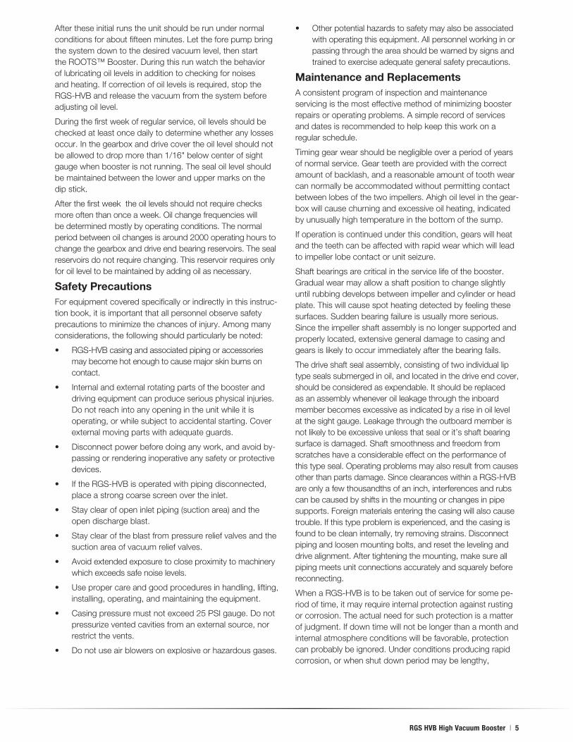
After these initial runs the unit should be run under normal conditions for about fifteen minutes. Let the fore pump bring the system down to the desired vacuum level, then start the ROOTS™ Booster. During this run watch the behavior of lubricating oil levels in addition to checking for noises and heating. If correction of oil levels is required, stop the RGS-HVB and release the vacuum from the system before adjusting oil level.
During the first week of regular service, oil levels should be checked at least once daily to determine whether any losses occur. In the gearbox and drive cover the oil level should not be allowed to drop more than 1/16" below center of sight gauge when booster is not running. The seal oil level should be maintained between the lower and upper marks on the dip stick.
After the first week the oil levels should not require checks more often than once a week. Oil change frequencies will be determined mostly by operating conditions. The normal period between oil changes is around 2000 operating hours to change the gearbox and drive end bearing reservoirs. The seal reservoirs do not require changing. This reservoir requires only for oil level to be maintained by adding oil as necessary.
Safety PrecautionsFor equipment covered specifically or indirectly in this instruc-tion book, it is important that all personnel observe safety precautions to minimize the chances of injury. Among many considerations, the following should particularly be noted:
• RGS-HVBcasingandassociatedpipingoraccessoriesmay become hot enough to cause major skin burns on contact.
• Internalandexternalrotatingpartsoftheboosteranddriving equipment can produce serious physical injuries. Do not reach into any opening in the unit while it is operating, or while subject to accidental starting. Cover external moving parts with adequate guards.
• Disconnectpowerbeforedoinganywork,andavoidby-passing or rendering inoperative any safety or protective devices.
• IftheRGS-HVBisoperatedwithpipingdisconnected,place a strong coarse screen over the inlet.
• Stayclearofopeninletpiping(suctionarea)andtheopen discharge blast.
• Stayclearoftheblastfrompressurereliefvalvesandthesuction area of vacuum relief valves.
• Avoidextendedexposuretocloseproximitytomachinerywhich exceeds safe noise levels.
• Usepropercareandgoodproceduresinhandling,lifting,installing, operating, and maintaining the equipment.
• Casingpressuremustnotexceed25PSIgauge.Donotpressurize vented cavities from an external source, nor restrict the vents.
• Donotuseairblowersonexplosiveorhazardousgases.
• Otherpotentialhazardstosafetymayalsobeassociatedwith operating this equipment. All personnel working in or passing through the area should be warned by signs and trained to exercise adequate general safety precautions.
Maintenance and ReplacementsA consistent program of inspection and maintenance servicing is the most effective method of minimizing booster repairs or operating problems. A simple record of services and dates is recommended to help keep this work on a regular schedule.
Timing gear wear should be negligible over a period of years of normal service. Gear teeth are provided with the correct amount of backlash, and a reasonable amount of tooth wear can normally be accommodated without permitting contact between lobes of the two impellers. Ahigh oil level in the gear-box will cause churning and excessive oil heating, indicated by unusually high temperature in the bottom of the sump.
If operation is continued under this condition, gears will heat and the teeth can be affected with rapid wear which will lead to impeller lobe contact or unit seizure.
Shaft bearings are critical in the service life of the booster. Gradual wear may allow a shaft position to change slightly until rubbing develops between impeller and cylinder or head plate. This will cause spot heating detected by feeling these surfaces. Sudden bearing failure is usually more serious. Since the impeller shaft assembly is no longer supported and properly located, extensive general damage to casing and gears is likely to occur immediately after the bearing fails.
The drive shaft seal assembly, consisting of two individual lip type seals submerged in oil, and located in the drive end cover, should be considered as expendable. It should be replaced as an assembly whenever oil leakage through the inboard member becomes excessive as indicated by a rise in oil level at the sight gauge. Leakage through the outboard member is not likely to be excessive unless that seal or it’s shaft bearing surface is damaged. Shaft smoothness and freedom from scratches have a considerable effect on the performance of this type seal. Operating problems may also result from causes other than parts damage. Since clearances within a RGS-HVB are only a few thousandths of an inch, interferences and rubs can be caused by shifts in the mounting or changes in pipe supports. Foreign materials entering the casing will also cause trouble. If this type problem is experienced, and the casing is found to be clean internally, try removing strains. Disconnect piping and loosen mounting bolts, and reset the leveling and drive alignment. After tightening the mounting, make sure all piping meets unit connections accurately and squarely before reconnecting.
When a RGS-HVB is to be taken out of service for some pe-riod of time, it may require internal protection against rusting or corrosion. The actual need for such protection is a matter of judgment. If down time will not be longer than a month and internal atmosphere conditions will be favorable, protection can probably be ignored. Under conditions producing rapid corrosion, or when shut down period may be lengthy,

6 | Dresser Roots
protective treatment should be provided in the form of a vaporizing inhibitor. Zerust vapor capsules, or equivalent, is recommended.
After disconnecting the RGS-HVB inlet and discharge piping, seal both openings with covers made of wood, metal, or plastic over vapor barrier paper. To the inside of each cover attach a Zerust capsule or equivalent. The booster may be returned to service at any time without internal cleaning if inspection reveals no dirt or foreign material in the process chamber.
In general, major repairs are to be considered beyond the scope of maintenance work and should be performed by factory trained personnel. Warranty claims must be reported to the nearest distributor or sales office. Unauthorized disas-sembly during the warranty period may void the warranty.
Shaft Seal Replacement 615 RGS-HVBA consistent program of inspection and maintenance servicing is the most effective method of minimizing repairs or operating problems with the booster. A record of service and dates is recommended to keep preventive maintenance on a regular schedule.
If the need for repair is indicated, the unit must be drained of oil from the gearbox and drive end cover before any lifting or transporting is done. The oil reservoirs and case are separated by slinger seals only, and any tilting of the unit could introduce oil into the cylinder. If oil enters the cylinder the RGS-HVB will not perform properly due to vaporization of the oil. When the unit has been removed from service, and transported to a clean work area, the repairs can be done with instructions in this manual by a qualified mechanic.
Replacement of the drive shaft seals may be required at intervals, and this can be a field operation since only limited disassembly is required, and no mechanical adjustments are involved. Both seals should be replaced at the same time, even if only one appears to be defective. The following procedure should be used:
A. Removing Seals
1. Make sure oil has been drained from end cover sump and seal oil sump.
2. Remove the four long cap screws in the drive end cover, located at the 45 deg. Positions top and bottom. Replace these temporarily with four 3/8”-16X1” grade eight cap screws to hold the head plate flange tightly against the cylinder, and prevent breaking the seal between head plate and cylinder.
3. Remove all the remaining long cap screws holding the
end cover in place. Bump the cover flange carefully to break it’s joint to the head plate. Then work the cover off the two locating pins, and pull it off the drive shaft. Remove oil reservoir cover plate and gasket.
4. Remove both shaft seals together by pressing from one side of the cover. Pressing may be done from either side with use of a proper size arbor. Care must be taken so that the arbor does not contact or scratch the bore of the cover to damage the surface.
5. Carefully clean the seal housing bore, and inspect the oil reservoir for dirt. Make sure all surfaces are clean.
6. Inspect gasket, and slip cover back over the drive shaft and align with the locating pins. Insert four long cap screws evenly spaced, and pull the cover firmly against the head plate. Check concentricity of seal bore with the drive shaft by using a dial indicator. If concentricity varies more than .005”, remove the cover and install new seals per Steps 2 and 5 under operation B. Also modify Step 4 to permit rechecking bore concentricity at the outer seal bore after the inner seal is installed. If it is still not within limit specified, remove both locating pins and reposition the end cover to attain the best concentricity. After clamping securely and rechecking, drill for, and install the next larger size locating pins.
B. Installing New Seals
1. Lightly file off sharp or rough edges on the drive shaft shoulders and keyway, and cover these areas with masking tape. This will prevent damage to the seal lips as they slide along the shaft.
2. Install the inner seal first (after preparing it as discussed below) using an arbor press. Place the machined front surface of the end cover directly on the press table. Use a round arbor smaller than seal bore between the press ram and the seal. The arbor should be 1-7/8” diameter, and must not be allowed to make contact with the housing bore. Press the seal into the bore lip side first, until it’s metal face is flush with the back surface of the end cover. The seal back face should also be true with the machined front surface of the cover within .005” total indicator reading.
To prepare a seal for installation, first inspect it very carefully for notches or cuts in the sealing lips and for burrs on the outer metal rim. Metal burrs may be removed, but if lips are defective the seal must be discarded. Make sure there are no foreign material anywhere on the seal, then coat the outer edge of the metal lightly with a suitable high vacuum sealing compound. The inner lip which contacts the shaft should be coated with vacuum grease.
3. Install the new outboard seal from the outside, or front face of the cover, after preparation as above. Installation may be made either before or after the end cover is installed on the head plate. If before, follow the proce-dure outlined in Step 2 for arbor press work except with the end cover positioned front face up.
Table 3 – Normal Internal Clearances
A - Impeller Ends to Head Plates: Total Both Ends .018 - .024 inches
NOTE: When either impeller is pushed to a stop at either end, clearance at that end should not be less than .003 to .005 inches
B - Impeller tips to cylinder: .006 - .008 inches
C - Between Impellers (lobe to lobe) .014 - .018 inches
RGS HVB High Vacuum Booster | 7
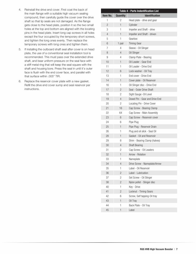
4. Reinstall the drive end cover. First coat the back of the main flange with a suitable high vacuum sealing compound, then carefully guide the cover over the drive shaft so that lip seals are not damaged. As the flange gets close to the head plate, position it so the two small holes at the top and bottom are aligned with the locating pins in the head plate. Insert long cap screws in all holes except the four occupied by the temporary short screws, and tighten the long ones evenly. Then replace the temporary screws with long ones and tighten them.
5. If installing the outboard shaft seal after cover is on head plate, the use of a conventional seal installation tool is recommended. This must pass over the extended drive shaft, and bear uniform pressure on the seal face with a stiff metal ring that will keep the seal square with the shaft and housing bore. Press the seal in until it’s outer face is flush with the end cover face, and parallel with that surface within .005” TIR.
6. Replace the reservoir cover plate with a new gasket. Refill the drive end cover sump and seal reservoir per instructions.
Table 4 - Parts Indentification List
Item No. Quantity Identification
1 2 Head plate - drive and gear
2 1 Cylinder
3 1 Impeller and Shaft - drive
4 1 Impeller and Shaft - driven
5 1 Gearbox
6 1 pair Timing Gear
7 4 Sleeve - Oil Slinger
8 4 Oil Slinger
9 4 Clamp Plate - Bearing
10 1 Oil Leader - Gear End
11 1 Oil Leader - Drive End
12 6 Lock washer - Oil Tray
13 1 End cover - Drive End
14 1 Cover plate - Oil Reservoir
16 1 Oil Slinger disc - Drive End
17 2 Seal - Outer Drive Shaft
18 2 Sight Gauge -Oil Level
19 4 Dowel Pin - Gear and Drive End
20 2 Locating Pin - Drive Cover
21 16 Cap Screw - Bearing Clamp
22 64 Cap Screw - Main Assembly
23 6 Cap Screw - Reservoir cover
24 6 Pipe Plug
25 1 Pipe Plug - Reservoir Drain
26 1 Plug and oil slick - Seal Oil
28 1 Gasket - Oil and Reservoir
29 8 Shim - Bearing Clamp (halves)
30 4 Shaft Bearing
31 2 Cap Screw - Oil Leaders
32 1 Arrow - Rotation
33 1 Nameplate
34 4 Drive Screw - Nameplate/Arrow
35 1 Label - Oil Reservoir
36 2 Label - Lubrication
37 2 Set Screw - Oil Slinger
38 2 Nylon pellet - Slinger disc
40 1 Key - Drive
41 2 Locknut - Timing Gears
42 6 Screw, Self tapping-Oil tray
43 1 Oil Tray
44 1 Back Plate - Oil Tray
45 1 Label

8 | Dresser Roots
615
RG
S H
VB
Ass
emb
ly D
raw
ing

www.dresser.com/rootsblowers
About Dresser, Inc.Dresser, Inc. is a leader in providing highly engineered
infrastructure products for the global energy industry. The
company has leading positions in a broad portfolio of prod-
ucts, including valves, actuators, meters, switches, regulators,
piping products, natural gas-fueled engines, retail fuel
dispensers and associated retail point-of-sale systems, and
air and gas handling equipment. Leading brand names within
the Dresser portfolio include Dresser Wayne® retail fueling
systems, Waukesha® natural gas-fired engines, Masoneilan®
control valves, Consolidated® pressure relief valves, and
Roots® blowers. It has manufacturing and customer service
facilities located strategically worldwide and a sales presence
in more than 150 countries.
About Dresser RootsDresser Roots, a major product brand of Dresser, Inc., is
the manufacturer of the original ROOTS™ blower, centrifugal
compressors and control systems. ROOTS® air and gas
moving equipment is used in a wide variety of applications,
including MVR (Mechanical Vapor ecompression), water
and wastewater treatment, flue gas desulphurization,
petrochemical and chemical processes, conveying, and
other general industrial applications.
Dresser Roots Houston,TexasHeadquarters•U.S.TollFreePhone:1877-363-ROOT(S)(7668)•DirectPhone:+1832-590-2600 Connersville,IndianaOperations•U.S.TollFreePhone:1877-442-7910•DirectPhone:+1765-827-9285 EuropeanOperations•Phone:+44(0)169552600•Email:[email protected] USA/CanadaSales•Phone:+1773-444-3360 Houston,TexasFactoryService•Phone:+1713-896-4810 MexicoCitySalesandFactoryService•Phone:+525558895811 DubaiSalesandFactoryService•Phone:+97148855481 MalaysiaSales•Phone:+60322672600 ChinaSales•Phone:+861084862440 ShanghaiFactoryService•Phone:+862158587638
©2010 Dresser, Inc. All rights reserved. • Printed in the U.S.A. • All information subject to change without notice. • Roots, Wayne, Waukesha, Masoneilan and Consolidated are registered trademarks of Dresser, Inc. • ROOTS, RAM and WHISPAIR are trademarks of Dresser, Inc.
ILRB-3008 rev. 0510