RFX85 Installation Guide - RadioManual · RFX85 Installation Guide . INTRODUCTION . The RFX85 is an...
4
RFX85 Installation Guide INTRODUCTION The RFX85 is an OEM replacement part for Magnum 10 meter amateur transceivers. The RFX85 includes the RF driver and final output stages and low pass filter section from a Magnum 10 meter amateur transceiver. The RFX85 does not work independently, but it is an integral part from a Magnum transceiver and is available for repair and replacement purposes. THEORY OF OPERATION – A basic understanding of what the RFX85 does and how it works. a) The RFX85 replaces the transceiver’s final amplifier stage and low pass filter section. The RFX85 is NOT a standalone amplifier. The RFX85 mounts to the back of the transceiver. b) Once installed, the transmitted RF signal from the output of the transceiver’s driver stage (or pre-driver stage) is sent to the RFX85 via the RF IN (Yellow) coaxial cable. c) The driver signal is then amplified through the RFX85’s ERF2030 (FET1) and then again through the ERF7530 (FET2). d) The amplified signal from the ERF7530 passes through the RFX85’s efficient low pass filter. e) A small portion of the signal is sampled through C19 and R9, then rectified through D3 and D4. This is sent to the S-meter detection circuit in the transceiver through the yellow wire. f) The final RF output signal of the RFX85 is sent back to the radio through the RF OUT coaxial cable (Red) where it is connected with the transceiver’s antenna connector*. * It is possible to attach the RF OUT coax directly to the antenna connector. However, it is recommended to attach it to the transceiver’s PCB because some transceivers come equipped with antenna warning systems, or other circuits, that are on ancillary boards between the recommended connection point and the antenna connector. RFX85 Installation for Magnum S-3, Magnum S-6, and Magnum S-9 10 Meter Amateur Transceivers with Main Printed Circuit Board Numbers* 9821R17 through 9821R21 * The printed circuit board number is found on the solder side of the main PCB at the front of the transceiver. 1) Test the transceiver and verify that both transmit and receive function correctly. It is important to verify the radio is operating prior to any installation. 2) Turn off the transceiver and disconnect it from all power sources. 3) Remove the stock heatsink from the rear panel of the transceiver. 4) Using a 1/8 inch drill bit, drill out the two holes that were used for mounting the stock heatsink. 5) In the rear panel of the transceiver, drill a 3/8 inch to 1/2 inch diameter hole centered between the two 1/8 inch holes that were drilled in step 4. It is recommended to drill this hole so that it does not interfere with the mounting of the original finals and driver transistors – in case the radio needs to be returned to stock configuration at a later date. WARNING: After drilling, make sure that no drill shavings and debris is in the transceiver. 6) Unsolder and remove the following parts from the transceiver: J77, J98, L31, L51, TR43, TR56, D86, C158, C164, and C209. These parts are circled in red on the parts layout diagram below. NOTE: J77 and J98 are circled together. D86 and C164 are circled together. 7) Install a jumper wire across the 2 holes where L31 was removed.
Transcript of RFX85 Installation Guide - RadioManual · RFX85 Installation Guide . INTRODUCTION . The RFX85 is an...
RFX85 Installation Guide
INTRODUCTION The RFX85 is an OEM replacement part for Magnum 10 meter amateur transceivers. The RFX85 includes the RF driver and final output stages and low pass filter section from a Magnum 10 meter amateur transceiver. The RFX85 does not work independently, but it is an integral part from a Magnum transceiver and is available for repair and replacement purposes. THEORY OF OPERATION – A basic understanding of what the RFX85 does and how it works.
a) The RFX85 replaces the transceiver’s final amplifier stage and low pass filter section. The RFX85 is NOT a standalone amplifier. The RFX85 mounts to the back of the transceiver.
b) Once installed, the transmitted RF signal from the output of the transceiver’s driver stage (or pre-driver stage) is sent to the RFX85 via the RF IN (Yellow) coaxial cable.
c) The driver signal is then amplified through the RFX85’s ERF2030 (FET1) and then again through the ERF7530 (FET2). d) The amplified signal from the ERF7530 passes through the RFX85’s efficient low pass filter. e) A small portion of the signal is sampled through C19 and R9, then rectified through D3 and D4. This is sent to the S-meter
detection circuit in the transceiver through the yellow wire. f) The final RF output signal of the RFX85 is sent back to the radio through the RF OUT coaxial cable (Red) where it is
connected with the transceiver’s antenna connector*. * It is possible to attach the RF OUT coax directly to the antenna connector. However, it is recommended to attach it to the transceiver’s PCB because some transceivers come equipped with antenna warning systems, or other circuits, that are on ancillary boards between the recommended connection point and the antenna connector.
RFX85 Installation for Magnum S-3, Magnum S-6, and Magnum S-9 10 Meter Amateur Transceivers
with Main Printed Circuit Board Numbers* 9821R17 through 9821R21 * The printed circuit board number is found on the solder side of the main PCB at the front of the transceiver.
1) Test the transceiver and verify that both transmit and receive function correctly. It is important to verify the radio is operating prior to any installation.
2) Turn off the transceiver and disconnect it from all power sources. 3) Remove the stock heatsink from the rear panel of the transceiver. 4) Using a 1/8 inch drill bit, drill out the two holes that were used for mounting the stock heatsink. 5) In the rear panel of the transceiver, drill a 3/8 inch to 1/2 inch diameter hole centered between the two 1/8 inch
holes that were drilled in step 4. It is recommended to drill this hole so that it does not interfere with the mounting of the original finals and driver transistors – in case the radio needs to be returned to stock configuration at a later date. WARNING: After drilling, make sure that no drill shavings and debris is in the transceiver.
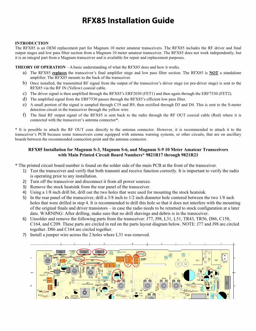
6) Unsolder and remove the following parts from the transceiver: J77, J98, L31, L51, TR43, TR56, D86, C158, C164, and C209. These parts are circled in red on the parts layout diagram below. NOTE: J77 and J98 are circled together. D86 and C164 are circled together.
7) Install a jumper wire across the 2 holes where L31 was removed.

8) On the solder side of the radio PCB, remove C160 and C402. These parts are circled in red on the parts layout diagram below.
9) On the RFX85, disassemble the fuse holder on the positive (red) power lead so it will fit through the hole drilled in step 5. Open the fuse holder and carefully remove the glass fuse and wire from the plastic fuse holder.
10) Route the RFX85 wires and coax cables through the large hole drilled in step 5. 11) Reassemble the fuse holder assembly on the inside of the transceiver. 12) Using the supplied 40mm long machine screws and nylon-insert nuts, bolt the RFX85 to the transceiver.
a. Insert the 40mm machine screws through the holes in the back of the RFX85 (between the heatsink fins). b. Line up the screws with the 1/8 inch holes drilled in step 4, and hold the RFX85 to the transceiver. c. On the inside of the transceiver, use the nylon-insert nuts to secure the RFX85.
13) Locate the RF IN coax cable on the RFX85. This is the coax cable with the yellow color tubing that is next to the Orange wire on the PCB. Route the RF IN coax from the RFX85 through the slot on the transceiver’s PCB where TR43 and TR56 were removed. On the solder side of the transceiver PCB, solder the RF IN coax center conductor to the trace at the junction of C171 and J98. Solder the RF IN coax shield to DC ground. See diagram below.
14) Locate the RF OUT coax cable on the RFX85. This is the coax cable with the red color tubing. Route the RF OUT coax through the slot on the transceiver’s PCB where TR43 and TR56 were removed. On the solder side of the transceiver PCB, solder the RF OUT coax center conductor to the trace at the junction of L31 and C158. Solder the RF OUT coax shield to chassis ground. See diagram below.
15) Solder the positive (red) power lead from the RFX85 to the positive side of the transceiver’s DC IN jack. 16) Solder the negative (black) power lead from the RFX85 to the negative side of the transceiver’s DC IN jack.
RF IN Coax Center Conductor
RF IN Coax Shield (DC ground)
RF OUT Coax Center Conductor
RF OUT Coax Shield (chassis ground)

17) Locate the Orange wire from the RFX85 and route it through the slot on the transceiver’s PCB where TR43 and TR56 were removed. On the solder side of the transceiver PCB, solder the Orange wire to the center lead of TR51 in the transceiver. See diagram below.
18) Locate the Yellow wire from the RFX85 and route it through the slot on the transceiver’s PCB where TR43 and TR56 were removed. On the solder side of the transceiver PCB, solder the Yellow wire to the trace at the positive side of C164. See diagram below.
19) Locate the Blue wire from the RFX85 and route it through the slot on the transceiver’s PCB where TR43 and TR56 were removed. On the solder side of the transceiver PCB, solder the Blue wire to the trace at R272 that is closest to the front panel of the transceiver. This location is +8 volts in transmit only. See diagram below.
20) For S-9 Models Only – Do not perform this step on S-3 or S-6 models. Add a 1K ohm, ¼ watt resistor across R214 on solder side of the radio PCB. See diagram below.
21) For S Series Radios with ERF2030 Finals Only – Do not perform this step on S Series Radios with 2SC1969 final transistors. Unsolder and remove the jumper wire located between the C171 and C208 PCB locations. Then unsolder the capacitor located at C209 and reinstall it at location C171. See diagram on next page.
TR51 Center Lead Trace
C164 Positive Side Trace
R272 Trace – Closest to the Front Panel

22) Double check installation and confirm that all wires are installed correctly. 23) The RFX85 comes from the factory with the two variable resistors for adjusting the bias on the final and driver.
These are PRE SET at the factory and usually do not require any adjustment. You can however adjust them for optimum bias by doing the following.
24) Bias Adjustment. Unsolder the Yellow coax at the radio PCB. Next, connect a DC amp meter in series with the Orange wire. Turn the radio on, transmit into a dummy load and observe the amp meter. Note that you will have NO output on the watt meter during this test! Adjust VR1 to obtain 100mA reading. Turn the radio off and reattach the Orange wire. Next, connect the amp meter in line with the Red wire (positive DC power lead) going to the RFX85. Turn the radio on. Transmit into a dummy load and observe the amp meter. Adjust VR2 to obtain 100mA reading. Turn the radio off. Reattach the red wire and reattach the yellow coax to their appropriate locations.
25) Connect transceiver to power and test equipment and re-tune the transmit and receive sections of the transceiver as needed. WARNING: DO NOT SET AM CARRIER HIGHER THAN 15 WATTS ON TRANSCEIVER WITH RFX85 INSTALLED.
RFX85 Schematic
More technical information may be found at http://www.cbtricks.com/miscellaneous/accessories/index.htm
Remove jumper wire between C171 and C208 PCB locations
Move capacitor at C209 to the C171 PCB location