RFP No. MPBSCDCL/TENDER NO -69 September 2018 Bhopal …
563
Page 1 of 563 RFP No. MPBSCDCL/TENDER NO -69 September 2018 Bhopal Smart City Development Corporation Limited Construction and Development of HAAT BAZAAR under Smart City Area Based Development consisting of works RCC, Architectural Finishes, MEP Services, and Landscape works including operation & maintenance of project for 3 years REQUEST FOR PROPOSAL
Transcript of RFP No. MPBSCDCL/TENDER NO -69 September 2018 Bhopal …

Page 1 of 563
RFP No. MPBSCDCL/TENDER NO -69 September 2018
Bhopal Smart City Development
Corporation Limited
Construction and Development of HAAT BAZAAR under
Smart City Area Based Development consisting of
works RCC, Architectural Finishes, MEP Services, and
Landscape works including operation & maintenance of
project for 3 years
REQUEST FOR PROPOSAL

Page 2 of 563
INDEX
VOLUME – I
CLAUSE
NO.
DESCRIPTION PAGE
NO.
SECTION – 1
1-6 1 Notice Inviting Tender
2 Eligibility Criteria
3 MEMORANDUM (Annexure – I)
SECTION – 2
7-16
4 INSTRUCTIONS TO BIDDER(ITB)
5 Acceptance of Tender Conditions (Annexure – II)
SECTION - 3
17-55
GENERAL CONDITIONS OF CONTRACT(GCC)
6 Definitions
7 Performance Guarantee
8 Security Deposit/ Retention Money
9 Mobilization Advance
10 Secured Advance Against Non-Perishable Materials
11 Deviations / Variations Extent And Pricing
12 Escalation / Price Variation
13 Compensation for Delay
14 Action in Case Work Not Done As Per Specifications
15 Action in Case of Bad Work
16 Cancellation/Determination of Contract in Full or Part
17 Contractor Liable to Pay Compensation Even if Action Not
Taken Under Clause 11.0
18 Carrying Out Part Work at Risk & Cost of Contractor
19 Suspension of Works

Page 3 of 563
CLAUSE
NO.
DESCRIPTION PAGE
NO.
20 Termination of Contract on Death of Contractor
21 Time Essence of Contract & Extension for Delay
22 Time Schedule & Progress
23 Taxes and Duties
24 Income Tax Deduction (TDS)
25 GST
26 Royalty on Materials
27 Insurance of Works Etc
28 Payments
29 Measurements of Works
30 Computerized Measurement Books
31 Withholding and Lien in Respect of Sums Due from
Contractor
32 Work to be Executed in Accordance with Specifications,
Drawings, and Orders etc.
33 Materials to be Provided by the Contractor
34 Materials and Samples
35 Materials Procured with the Assistance of BSCDCL
36 Contractor to Supply Tools & Plants
37 Mobilization of Men, Materials and Machinery
38 Quality Assurance Program
39 Contract Coordination Procedures, Coordination Meetings
and Progress Reporting
40 Completion Certificate and Completion Plans
41 Prohibition of Unauthorized Construction & Occupation
42 Foreclosure of Contract by BSCDCL / Owner
43 Defects Liability Period
44 Restriction on Subletting

Page 4 of 563
CLAUSE
NO.
DESCRIPTION PAGE
NO.
45 Force Majeure
46 No Compensation Clause
47 Direction for Works
48 Work in Monsoon and Rain
49 Work on Sundays, Holidays and During Night
50 Water and Electricity
51 Land for Labor Huts/ Site Office and Storage Accommodation
52 Watch, Ward and Lighting of Work Place
53 Bitumen Work
54 Schedule of Quantities / Bill of Quantities
55 Water Proof Treatment
56 Indian Standards
57 Centering & Shuttering
58 Records of Consumption of Cement & Steel
59 Tests and Inspection
60 Works to be Open to Inspection
61 Borrow Areas
62 Care of Works
63 Co-Ordination with Other Agencies
64 Setting Out of the Works
65 Notice Before Covering Up the Work
66 Site Clearance
67 Set-Off of Contractor‘s Liabilities
68 Possession Prior to Completion
69 Employment of Personnel
70 Technical Staff for Work
71 Valuable Articles Found at Site

Page 5 of 563
CLAUSE
NO.
DESCRIPTION PAGE
NO.
72 Furnished Office Accommodation & Mobility Communication
to be Provided by Contractor
73 Materials Obtained from Dismantlement to be Owner‘s
Property
74 The Same upto Defect Liablity Period
75 Labour Laws
76 Labour Cess
77 Recovery of Compensation Paid to Workmen
78 Ensuring Payment and Amenities to Workers if Contractor
Fails
79 Change in Firm‘s Constitution to be Intimated
80 Indemnity against Patent Rights
81 Law Covering the Contract
82 Laws, Bye-Laws Relating to the Work
83 Contract Agreement
84 Manner of Execution of Agreement
85 Jurisdiction
86 SECTION – 4
Labour safety, health and regulations including forms 56-61
87 SECTION – 5
62-83
FORMS AND FORMATS
88 SECTION – 6
84-85
SPECIAL CONDITION OF CONTRACT(SCC)
89 SECTION – 7
86-120 90
SCOPE OF WORK EMPLOYERS REQUIREMNTS AND
TECHNICAL SPECIFICATIONS

Page 6 of 563
CLAUSE
NO.
DESCRIPTION PAGE
NO.
SECTION – 8
121-127 91 DRAWINGS
SECTION – 9
128-148 92 BILL OF QUANTITIES
SECTION – 10
93 Environment ,Health & Safety

Page 7 of 563
SECTION-1
NOTICE INVITING TENDER

Page 8 of 563
Bhopal Smart City Development Corporation Limited
NOTICE INVITING e-TENDER (NIT)
BSCDCL invites online percentage rate /item rate tender as per schedule as under:
Tendering Document No. : MPBSCDCL/TENDER NO -69
Name of the Work : Construction and Development of Haat
Bazar Including Structure for parking,
Landscaping, Electrification, Plumbing,
Fire Fighting and ICT under Smart City
Area Based Development
Brief Scope of Work : Construction of Haat Bazar Including
Structure for parking, Landscaping,
Electrification, Plumbing, Fire Fighting and
ICT.
Estimated Cost : Rs. 41.45 Cr (Forty One Crore Forty Five
Lakh Rupees Only)
Period of Completion : (12 Months including raining season for
construction) and (36 Months for O&M After
commissioning of Project)
Earnest Money Deposit : Rs. 21,00,000/- (Twenty One lakhs rupees
only)
Non-refundable cost of e- Tender
Document
: Rs. 50,000/- (Fifty Thousand rupees only)
Purchase of Tender Start Date : 01/09/2018 21:00 Hrs
Purchase of Tender End Date : 24/09/2018 17:30 Hrs
Last date & time of submission of
Online Tender( Bid Submission)
: 24/09/2018 23:00 Hrs
Period during which hard copy of the
documents as per NIT shall be
submitted.(With all technical
credentials)
: 25/09/2018 12:00 Hrs
Date & Time of Opening of technical
Tender
: 25/09/2018 15:00 Hrs

Page 9 of 563
Date & Time of Opening of Financial
Tender
: Will be intimated later to successful Bidder
Validity of offer 180 days from the date of Submission of
price bid
Pre-Tender Meeting & Venue 10/09/2018 at 12.00 Hrs. At BSCDCL,
Bhopal Office
The tender document can be downloaded from www.mpeproc.gov.in “Corrigendum, if
any, would appear only on the www.mpeproc.gov.in web site and not to be
published in any News Paper”.
The tenderer if required may submit queries in writing on E-mail Id.
[email protected] before 09/09/2018 up to 23:59 Hrs.

Page 10 of 563
INSTRUCTION TO BIDDER:
The invitation for bids is open to all eligible bidders who may be proprietary firms,
partnership firms or companies registered under company‘s act 1956 and meeting
following criteria;
1. Joint Ventures/Consortium is allowed.
Joint venture consortium of Maximum Two firms/ members / companies, as
partners shall be allowed for the works.
All the Members of the JV shall be jointly and severally responsible for this
Contract. The Member of the JV holding highest stake shall be the Lead Partner.
The JV shall comply with the following requirements:
(a) A Joint venture agreement must be submitted along with the documents in
which minimum share of lead member shall have to be 60% and share of other
members, individually shall not be less than 26%.
(b) All the members of the Joint Venture firms shall have to collectively satisfy
all the criteria mentioned.
Note:
In case, the applicant/JV partner has achieved physical & financial performance for
the criteria mentioned above in past, in joint venture with other Contractor (other
than present JV partner), the portion of the work (physically and financially) of the
contractor included in their Joint Venture Agreement in original contract work shall
only be considered for evaluation purpose.
In joint venture consortium the lead partner shall only be an Indian citizen,
Indian partnership firm or Indian private/ public limited company.
The lead member shall be registered contractor in of appropriate class with the
Central Govt. / State Governments or Central / State Government Undertakings.
(c) The individual members who join in JV shall have to give an undertaking that
they will maintain status-quo till the completion of the work, if the work is
awarded to the JV Consortium, the same JV Consortium shall be maintained till
the satisfactory completion of the work. This undertaking shall be submitted on
Stamp paper duly signed by authorized signatory, which shall be registered.
(d) In case of Bidder participating as a Joint Venture, on his selection for award of
contract, all the partners/members of the Joint Venture will have to sign the
Contract with the employer and will be jointly and severally liable for
performance of the contract. Award of Contract will be in the name of Joint
Venture consortium which will be considered as ―Legal Entity‖ as far as this
Bid/ Contract is concerned.
(e) The Bid, and in case of a successful bid, the Form of Contract Agreement,
shall be signed with the name of Joint Venture which will be legally binding on
all the partners;
(f) Lead partner shall be declared as Prime Bidder authorized to be in charge; and
this authorization shall be evidenced by submitting a Power of Attorney signed
by legally authorized signatories of all the partners;

Page 11 of 563
(g) The member in charge shall be authorized to incur liabilities, receive payments
and receive instructions for and on behalf of any or all partners of the Joint
Venture and the entire execution of the contract including defect liability period;
(h) All members of the Joint Venture shall be jointly and severally liable for the
execution of the Contract in accordance with the Contract terms, and a relevant
statement to this effect shall be included in the Authorization mentioned under
(b) above as well as in the Bid Form and the Form of Contract Agreement (in
case of a successful Bid); and,
(i) A copy of the stamped and notarized agreement entered into by the Joint
Venture partners shall be submitted with the Bid. Roles, responsibilities and
financial stakes of all members of the Joint Venture consortium shall be clearly
and unambiguously prescribed in the Joint Venture agreement. In case of non
prescription, the JV agreement will be declared as invalid and the bid will be
treated as non responsive.
(j) In case of Joint Venture financial strengths of each of the JV members
individually shall not be less than Minimum Qualifying Criteria worked out in
proportionate to their financial stakes in the JV. In case of physical criteria, the
summation of performance of each JV member shall be considered for fulfilling
the criteria without considering their stake in the JV agreement.
Each JV member shall have required registration certificate, existence of company
as per tender requirement. Each member shall satisfy these requirements
separately.
(k) The contractors participating in the name and form of a Joint Venture
consortium shall have to clearly and unambiguously define the role,
responsibilities and financial stake of each of the partners, the lead partner
shall also have to be defined. On award of contract to such a Joint Venture
consortium, each of the members of the Joint Venture consortium shall have to
sign the Contract. Each member of the JV shall be jointly and severally
responsible for the performance of the contract.
(l) An original notarized copy of the agreement as prescribed in Form-8 entered
into by the joint venture partners shall be submitted with the bid. It should also
distinctly show the financial participation of each member of the joint venture
and the responsibility of each member as regards planning and execution of
the work.
In case of conflict between the terms in contract agreement and the Joint
Venture documents, the terms in the contract agreement shall prevail.
2. Equipment Capabilities:
The Bidder(s) shall have minimum equipment in full working order, as listed below,
and must demonstrate that based on known commitments, they will be available
for timely use in the proposed contract. The bidder should, undertake their own
studies and furnish with their bid, a detailed construction planning and
methodology supported with assessment study of requirements of
equipment/plants & machineries to allow the employer to review their proposal.
The bidder will ensure his commitment to make the arrangements of the required

Page 12 of 563
equipment on the day of commencement or with respect to the progress of the
work in phases, as per the instructions of site in charge on an undertaking on Rs.
100 stamp paper or of value as approved by Client to be submitted along with the
Bid.
The quantity mentioned is the minimum requirement; however it is in the obligation
of the Contractor to deploy/hire additional equipment and machinery as per
requirement of work.
Sr.
No
Equipment Minimum
Requirements
1 JCB / Excavators 1 no
2 Excavator 1 no
3 Rock/ Concrete pneumatic
breaker
1 no
4 Dewatering Pumps 2 nos
5 Needle Vibrators 2 nos
6 Plate Vibrators 2 nos
3. Personnel Capability
Contractor must produce documentary evident having the following staff on their
establishment atleast six months prior to submission of bid and during the duration
of contract and should submit undertaking stating that this staff or equivalent will
be deployed on site after award of contract as per necessity and instruction of
Engineer in Charge. Project shall be handled by a project manager having at least
BE civil with min. 10 yr. experience in executing Building project/Infrastructure
Project.
Sr.
no
Post Qualification Minimum
Requirements
1 Project
Manager
At least BE-civil with min. 10 years
experience in executing building
project/Infrastructure Project
1 no
2 Site Engineer At least BE-civil with min. 5 years
experience in executing building
project/Infrastructure Project
1 no
3 Project
planning
At least BE-civil with min. 5 years
experience in executing high rise
building project/Infrastructure
1 no

Page 13 of 563
Engineer Project
4 Supervisory
Staff
Construction supervisor with
minimum 5 years experience
2 nos
5 Design
Manager
(Graduate
Engineer)
Graduate Engineer with min 10
years experience
1 no
6 Safety Officer Graduate or Diploma Engineer with
5 years of Experience
1 no

Page 14 of 563
ELIGIBILITY CRITERIA FOR BIDDER:
To qualify for award of the contract, bidders are advised to note the minimum
qualification criteria specified below;.
1. Registration: The Bidder shall be registered contractor in of appropriate class with
the Central Govt. / State Governments or Central / State Government Undertakings.
2. Similar nature of Work: The Bidder in their own name should have satisfactorily
executed the work of similar nature Semi Govt. / Govt. & Public / Private Sector
Organizations in India, during last 7 years ending last day of month previous to the one
in which bids are invited as a prime Contractor.
Three similar completed works of similar nature each costing not less than 40%
of the estimated cost
OR
Two similar completed works of similar nature each costing not less than 50% of
the estimated cost.
OR
One completed work of similar nature of costing not less than 80 % of the
estimated cost.
Note:
a) The value of executed works shall be brought to current costing level by
enhancing the actual value of work at compound rate of 10 % per annum;
calculated from the date of completion to last date of receipt of applications for
tenders.
b) Similar works means Civil/Landscaping works related to
Gardens/Residential buildings/Commercial buildings/Multipurpose Hall as
main contractor.
c) The Bidder should demonstrate through submission of experience
certificates for collective experience of handling the following disciplines of work
in the above contracts:
i. Civil Works, structural work (RCC & steel)
ii. Landscaping Finishes works
iii. MEP works
d) Bidder should submit Client/Users Certificate of satisfaction for the work
they have executed

Page 15 of 563
3. Turnover: The average annual financial turnover during the last 3 years ending
2017-18 should not be less than 30% of the estimated cost. To ascertain this,
Bidder(s) shall furnish the financial statement (Audited balance sheet) duly certified by
Chartered Accountant.
4. Bid Capacity: The bid capacity of the bidder is required to be more than or equal
to estimated cost of the work.
The bid capacity of the prospective bidders will be calculated as under:
Assessed Available Bid Capacity = (A* N* 2 - B)
Where,
A = Maximum value of Civil Engineering works executed in any one year (year means
Financial year) during the last seven years (updated to the price level of the Financial
year in which bids are received at a rate of 10% per year) taking into account the
completed as well as works in progress.
N = Number of years prescribed for completion of the Project/Works,
B = Value of existing commitments (only allotted works) on the last date of submission
of bids as per bidding document and on-going works to be completed during the period
of completion of the Project/Works for which these bids are being invited.
Note: The statement showing the value of existing commitments and on-going works
as well as the stipulated period of completion remaining for each of the works listed
should be attached along with certificates duly signed by the Engineer- in- Charge, not
below the rank of an Executive Engineer or CA Certified.
Even though the bidders meet the above qualifying criteria, they are subject to be
disqualified if they have: made misleading or false representation in the forms,
statements and attachments submitted in proof of the qualification requirements;
and/or Record for poor performance such as abandoning the works, not properly
completing the contract, inordinate delays in completion, litigation history, or financial
failures etc.
Financial Year Turnover/ Cost of
Executed work
Effective cost of executed work at
previous completed financial year‟s
price level
2011-2012 G 1.77 x G
2012-2013 F 1.61 x F
2013-2014 E 1.46 x E
2014-2015 D 1.33 x D
2015-2016 C 1.21 x C
2016-2017 B 1.10 x B
2017-2018 A 1.0 x A

Page 16 of 563
5. Net worth: The Bidder(s) net worth should be positive in the last year (2017-18).
6. Physical Criteria:
a) The Bidder should have completed at-least one Landscape works project
costing not less than 5 Crore within last five years.
b) The Main Contractor should get the specialized works i.e. MEP Works
executed through nominated subcontractor duly approved by the Engineer-in-
charge of BSCDCL whose qualifying criteria are as mentioned in the SCC.
The Bidder should submit affidavit mentioning that they will execute specialised works
through nominated sub- contractors if specialized works are to be got executed
through Nominated sub –contractors or else the requisite experience/expertise as per
PQC shall be available in house.
7. Bidder shall have valid registration in GST registration, EPF Registration
Certificate & PAN Card.
8. The bidder should not got black listed by any government organization
(Central/State/PSU), bidder should submit affidavit signed by Director of the company.
Note to eligibility criteria:-
I. The bidder should necessarily submit completion certificate of the
Qualifying works from the client/user/ duly signed by an officer not below the rank
of Executive Engineer or equivalent of the concerned organization.
II. The Bidder shall submit the audited balance sheets / CA certified turnover
for last 3 years (2015-16, 2016-17, and 2017-18).
III. For the purpose of determination of turnover of the bidder, only turnover
from building construction projects shall be considered. This shall be backed by a
certificate from the Statutory Auditors of the company/Chartered Accountant.
Turnover from real estate development, sale of RMC, trading or sale of flats or
offices shall not be considered for evaluation.
IV. For the purpose of determining the relationship of the Bidder with their
group companies, only the following documents such as the Annual Report,
Balance Sheet or the Auditor Certificate, shall be considered.
V. Net worth shall be calculated as the sum of share capital and free reserves
and surplus.
VI. Accumulated losses if not adjusted in reserves and surplus and shown
separate in the balance sheet shall be deducted from the sum of share capital and
free reserves and surplus. Reserves on account of revaluation of fixed assets shall
be excluded.
VII. BSCDCL shall have the authority to make enquiries with the bidder‘s
bankers and auditors.
VIII. The bidders shall indicate information regarding any litigation or arbitration
resulting from contracts executed by the bidder in the last five years. The

Page 17 of 563
information shall include the name of the parties concerned, disputed amount,
cause of litigation & matter in dispute.
DOCUMENTS COMRISING THE BID :
The Bidders should additionally submit the following details in their Bid along with
documents mentioned in instruction to bidder and eligibility criteria for bidder but
not limited to the same:
1. An Organization Chart of administration and execution of the
contract showing the deployment of key personnel at Site with individual tasks
2. Copies of original documents defining the constitution or legal status,
place of registration and principal place of business; written Power of Attorney
authorizing the signatory of the bid to commit and bind the Bidder, details of
arbitrations and litigations.
3. A letter of authority to seek references from the bidders‘ bankers and
previous / existing Employer‘s.
4. Proposed general programme (Proposed Schedule and cash flow
estimate in percentage form only) / method statements / Quality Plan / Site
Management Plan in sufficient detail to demonstrate the adequacy of the
bidder's proposals to meet the technical specifications and the completion
time referred to in bid document.
5. All the document in support for meeting the Qualification Criteria
6. Signed copy of Pre-Bid Meeting held, if any.
7. Copies of all schedules, Technical Specifications and Deviations, if any,
drawings, literature, brochures.
8. Proposed Safety plan and procedures that shall be followed during
the execution of the Works
9. List of equipment / plant and machinery proposed to be deployed
for executing the Contract in line with proposed general program/method
statement . Availability (either owned or leased or by procurement) of key and
critical equipment for the Works list of equipment to be enclosed with the bid.
10. Experience in handling Similar Projects to be supported by WO/PO
Copies, Project Completion certificate , Project Status Report (duly certified by
respective authority) and Performance Certificates from clients.
Even though the bidders meet the above qualifying criteria, they are liable to be
disqualified if they have;
(a) Made misleading or false representations in the forms, statements and attachments
submitted by them which comes to the knowledge of Employer; and/ or;
(b) Record of poor performance such as abandoning the works, not properly
completing the contract, inordinate delays in completion, financial failures, etc.

Page 18 of 563
Evaluation Criteria:
The lowest evaluated rates including O&M for three years will be considered at the time of
evaluation.
Page 19 of 563
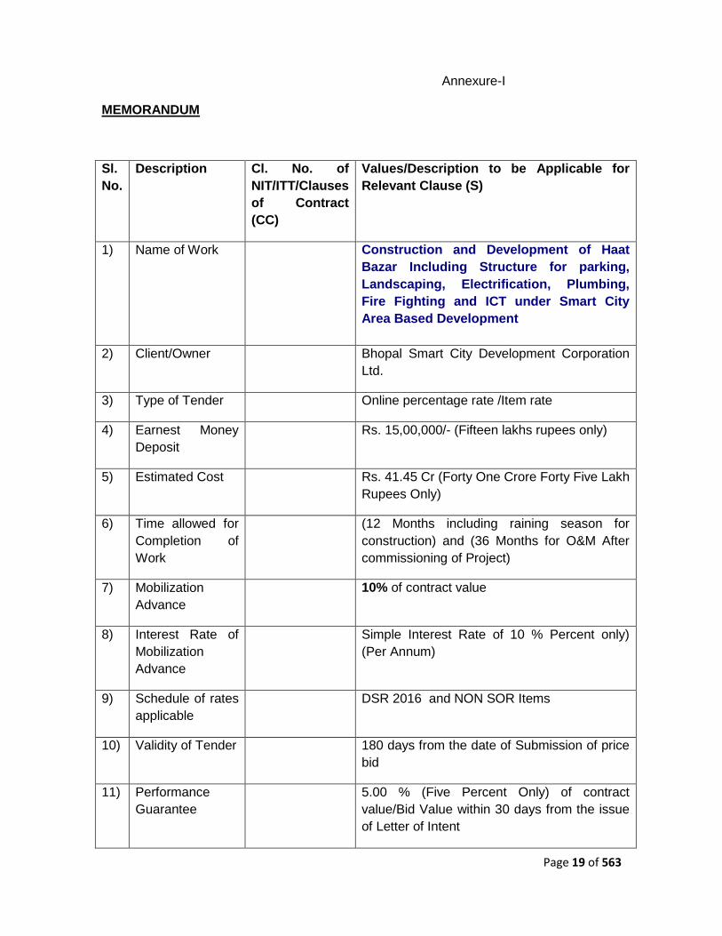
Annexure-I
MEMORANDUM
Sl.
No.
Description Cl. No. of
NIT/ITT/Clauses
of Contract
(CC)
Values/Description to be Applicable for
Relevant Clause (S)
1) Name of Work Construction and Development of Haat
Bazar Including Structure for parking,
Landscaping, Electrification, Plumbing,
Fire Fighting and ICT under Smart City
Area Based Development
2) Client/Owner Bhopal Smart City Development Corporation
Ltd.
3) Type of Tender Online percentage rate /Item rate
4) Earnest Money
Deposit
Rs. 15,00,000/- (Fifteen lakhs rupees only)
5) Estimated Cost Rs. 41.45 Cr (Forty One Crore Forty Five Lakh
Rupees Only)
6) Time allowed for
Completion of
Work
(12 Months including raining season for
construction) and (36 Months for O&M After
commissioning of Project)
7) Mobilization
Advance
10% of contract value
8) Interest Rate of
Mobilization
Advance
Simple Interest Rate of 10 % Percent only)
(Per Annum)
9) Schedule of rates
applicable
DSR 2016 and NON SOR Items
10) Validity of Tender 180 days from the date of Submission of price
bid
11) Performance
Guarantee
5.00 % (Five Percent Only) of contract
value/Bid Value within 30 days from the issue
of Letter of Intent

Page 20 of 563
12) Security
Deposit/Retention
Money
5.00% (Five Percent Only) of the gross value
of each running bill.
13) Time allowed for
starting the work
The date of start of contract shall be reckoned
from 10 days after the date of agreement.
14)
Deviation limit
beyond as per
tender document
except
foundation.
Building work as
per requirement.
Annual repair &
maintenance of buildings
As per requirement.
Note:-The Deviation Limit of Building Work
shall also apply for combined works (Building).
For SOR Items unlimited and NON SOR items
±30%. Beyond this, as per mutual agreed
rates.
15) Deviation limit
beyond as per
tender document
shall apply
for Foundation
Building work as
per requirement
Annual repair &
maintenance of buildings
as per requirement
Note:-The Deviation Limit of Building Work
shall also apply for combined works. For SOR
Items unlimited and NON SOR items ±30%.
Beyond this, as per mutual agreed rates.
16) Escalation All rates as per B i l l of Quantities (BOQ)
quoted by contractor shall be firm and fixed for
entire contract period as well as extended
period for completion of the works.
No escalation shall be applicable on this
contract.
17 Operation and
Maintenance
Period
Three (3) years after successful
commissioning of all Tendered works
17) Defects Liability
Period
Three (3) years after successful
commissioning of all works i.e upto
completion of Operation and Maintenance
period
The intending tenderer must read the terms and conditions of BSCDCL carefully. He should only submit his tender if he considers himself eligible and he is in possession of all the documents required.

Page 21 of 563
Information and Instructions for Tenderers posted on Website(s) shall form part of tender Document.
The Tender Document as uploaded can be viewed and downloaded free of cost by anyone including intending tenderer. But the tender can only be submitted after uploading the mandatory scanned documents .
The Bidder shall submit the Technical BID & Financial Bid online through e-procurement portal www.mpeproc.gov.in in comprising of the following documents along with supporting documents as appropriate:
Checklist for Online Submission: Envelope (A, B and C)
(a) Envelope-A will contain: (Hardcopy and online submission is necessary)
1. Proof of e-payment towards cost of tender document/ Acknowledgement
towards cost of tender fee submission
2. Proof of online payment through e-portal www.mpeproc.gov.in/ o r Bank
Guarantee of any Nationalized or Commercial Scheduled Bank against EMD in
favor CEO, BSCDCL shall be as per Notice Inviting e- tender.
(b) Envelope-B will contain: (Hardcopy and online submission is necessary)
1. Scanned copy of all approved/authenticated ―Eligibility Criteria for Bidder‖
documents as per Para of this RFP.
2. Letter of Acceptance of tender condition unconditional as per format
enclosed
3. Certificate of Financial Turnover duly certified by CA as indicated above.
4. GST registration number, EPF registration, PAN No.
5. All pages of the entire Corrigendum (if any) duly signed by the authorized
person.
6. Affidavit as per ―Appendix-O‖ of tender document.
7. Acceptance letter and Affidavit/Undertaking for Blacklisting/ Debar.
8. Should submit the list of tools plant and machinery.
9. Joint venture agreement in prescribed format if applicable.
10. Any other documents as asked in RFP document.
(c) Envelope-C will contain: (Only online submission is necessary)
The Financial Bids shall be uploaded online only strictly in the prescribed format.
If any condition or conditional rebate is offered by the tenderer, their tender shall summarily be rejected.

Page 22 of 563
The tenderers are required to quote strictly as per terms and conditions, specifications, standards given in the tender documents and not to stipulate any deviations.
After submission of the tender the tenderer can re-submit revised tender any number of times but before last time and date of submission of tender as notified.
When it is desired by BSCDCL to submit revised financial tender then it shall be mandatory to submit revised financial tender. If not submitted then the tender submitted earlier shall become invalid. On opening date, the tenderer can login and see the tender opening process. Contractor can upload documents in the form of JPG format and PDF format.
If the contractor is found ineligible after opening of tenders, his tender shall become invalid and cost of tender document and processing fee shall not be refunded.
If any discrepancy is noticed between the documents as uploaded at the time of submission of tender and hard copies as submitted physically by the contractor the tender shall become invalid and cost of tender document and processing fee shall not be refunded.
Notwithstanding anything stated above, BSCDCL reserves the right to assess the capabilities and capacity of the tenderer to perform the contract, in the overall interest of BSCDCL. In case, tenderer‘s capabilities and capacities are not found satisfactory, BSCDCL reserves the right to reject the tender.
Examination of Technical Bids and Determination of Responsiveness:
1. Prior to detailed evaluation of Technical Bids, the Employer will determine
whether each Bid
(a) meets the eligibility criteria defined in Clause
(b) has been properly signed by an authorized signatory (accredited
representative) holding power of Attorney in his favor.
(c) is accompanied by the required Bid security and;
(d) is responsive to the requirements of the Bidding documents.
2. A substantially responsive Technical Bid is one which conforms to all the
terms, conditions and specification of the Bidding documents, without material
deviation or reservation. A material deviation or reservation is one
(a) which affects in any substantial way the scope, quality or performance
of the works;
(b) which limits in any substantial way, the Employer's rights or the
Bidder's obligations under the Contract; or
3. If a Technical Bid is not substantially responsive, it will be rejected by the
Employer, and may not subsequently be made responsive by correction or
withdrawal of the non-conforming deviation or reservation.
Instructions for financial bid submission-
In case of Percentage Rate Tender, Contractor must ensure to quote single percentage
Page 23 of 563
rate in attached financial bid format. Quote should be in percentage higher or below on
the SOR Rates the same is to quoted in the form of decimal only. For example if
contractor wants to quote 5 percent higher then he have to quote 1.05 and if he wants
to quote 5 [percent below he have to quote 0.95 in given column of financial bid sheet.
In case of Item Rate Tender, price shall be entered against each item in the Bill of Quantities / Schedule of Quantities. The cost of item against which the contractor has failed to enter a rate or price shall be deemed to be covered by rates and prices of other items in Bill of Quantities / Schedule of Quantities and no payment shall be made for the quantities executed for items against which rate has not been quoted by the contractor.
In addition to this, while selecting any of the cells a warning appears that if any cell is left blank the same shall be treated as ―0‖. Therefore, if any cell is left blank and no rate is quoted by the tenderer, rate of such item shall be treated as ―0‖ (ZERO).
i. Financial Bid format is uploaded in Excel Format in www.mpeproc.gov.in. At the time
of financial bidding, bidder is requested to download the file, and update the same.
ii. For SOR items bidder need to quote 1 plus percentage higher of below the quoted rate
for example if bidder wants to quote 5% higher the SOR price then he have to
quote1.05 and similarly if he wants to quote 5% below the SOR price then he have to
quote0.95.
iii. For Non SOR items bidder can quote for individual item rates in respective financial bid
sheet.
iv. Bidders are requested to check final figure in all the totals of all sheets. BSCDCL is
not responsible for errors in the financial bid document.
v. Bidders are required to upload the updated financial bid in the prescribed excel format
in the www.mpeproc.gov.in at the time of final financial bid submission.

Page 24 of 563
.
SECTION-2
INSTRUCTIONS TO BIDDER

Page 25 of 563
Instruction to Tenderer (ITT) A. GENERAL INSTRUCTIONS: 2.1. General terms of Bidding- 2.1.1 No Bidder shall submit more than one BID for the Project. 2.1.2 The Feasibility Report / Preliminary Project Report of the Project has been
assessed however the Bidders are expected to carry out their own surveys, investigations and other Preliminary examination of the Project before submitting their Bids. Nothing contained in the attached drawings/BOQ shall be binding on the BSCDCL nor confer any right on the Bidders, and the BSCDCL shall have no liability whatsoever in relation to or arising out of any or all contents of TENDER.
2.1.3 Notwithstanding anything to the contrary contained in this RFP, the Preliminary terms
specified in the draft Agreement shall have overriding effect; provided, however, that any conditions or obligations imposed on the Bidder hereunder shall continue to have effect in addition to its obligations under the Agreement.
2.1.4 The BID shall be furnished in the financial bid format attached separately in the Excel
format
1. BID to be quote 1 plus % above or below (for Example. If want to quote 5%
above then write 1.05 and if want to quote 5% below then write 0.95) for the SOR
sheets.
2. BID shall be quoted item wise in the given excel sheet for the NON SOR items.
2.1.5 The Bidder shall deposit a BID Security (EMD) of (Rs. 21,00,000/- (Twenty One lakhs
rupees only) in accordance with the provisions of this RFP. The Bidder has to provide
the BID Security (EMD) through online payment or in the form of a Bank Guarantee
acceptable to the BSCDCL, as per format.
Company Name: Bhopal Smart City Development Corporation Ltd.
Bank Name: Allahabad Bank.
Branch Address: Arera Colony, Bhopal
A/C no. : 50327343809
IFSC Code: ALLA0210197
PAN No. : AAGCB6537N
TIN No. : 23889236926
Service Tax No. : AAGCB6537NSD001
GST no: 23AAGCB6537N1ZE.
2.1.6 The validity period of the Bank Guarantee, shall not be less than 180 (one hundred and eighty) days from the BID Due Date, inclusive of a claim period of 60 (Sixty) days, and may be extended as may be mutually agreed between the BSCDCL and the Bidder.

Page 26 of 563
2.1.7 The BID shall be summarily rejected if it is not accompanied by the BID Security. The BID Security shall be refundable no later than 150 (one hundred and fifty) days from the BID Due Date except in the case of the Selected Bidder whose BID Security shall be retained till it has provided a Performance Security under the Agreement.
2.1.8 The Bidder should submit a Power of Attorney as per the format, authorizing the
signatory of the BID to commit the Bidder. 2.1.9 Any condition or qualification or any other stipulation contained in the BID shall
render the BID liable to rejection as a non-responsive BID. 2.1.10 The BID and all communications in relation to or concerning the Bidding Documents
and the BID shall be in English language. 2.1.11 The documents including this RFP and all attached documents, provided by the
BSCDCL are and shall remain or become the property of the BSCDCL and are Transmitted to the Bidders solely for the purpose of preparation and the submission of a BID in accordance herewith. Bidders are to treat all information as strictly confidential and shall not use it for any purpose other than for preparation and submission of their BID.
2.1.12 The provisions of this Clause shall also apply mutatis mutandis to BIDs and all other documents submitted by the Bidders, and the BSCDCL will not return to the Bidders any BID, document or any information provided along therewith.
2.1.13 This RFP is not transferable.
2.1.14 Any award of Project pursuant to this RFP shall be subject to the terms of Bidding
Documents and also fulfilling the criterion as mentioned in tender document. 2.1.15 While bidding is open to persons from any country, the following provisions shall
apply then the Eligibility of such Bidder shall be subject to approval of the BSCDCL from national security and public interest perspective. The decision of the BSCDCL in this behalf shall be final and conclusive and binding on the Bidder. The holding or acquisition of equity or control, as above, shall include direct or indirect holding/ acquisition, including by transfer, of the direct or indirect legal or beneficial ownership or control, by persons acting for themselves or in concert and in determining such holding or acquisition, the BSCDCL shall be guided by the principles, precedents and definitions contained in the Securities and Exchange Board of India (Substantial Acquisition of Shares and Takeovers) Regulations,1997, or any substitute thereof, as inforce on the date of such acquisition. The Bidder shall promptly inform the BSCDCL of any change in the shareholding, as above, and failure to do so shall render the Bidder liable for disqualification from the Bidding Process.
2.1.17 Notwithstanding anything to the contrary contained herein, in the event that the Bid Due Date falls within three months of the closing of the latest financial year of a Bidder, it shall ignore such financial year for the purposes of its Bid and furnish all its information and certification with reference to the 5 (five) years or 1 (one) year, as the case may be, preceding its latest financial year. For the avoidance of doubt, financial year shall, for the Purposes of a Bid hereunder, mean the accounting year
followed by the Bidder in the course of its normal business. Latest Financial Year will
be (2017-2018)

Page 27 of 563
2.1.18 Any entity which has been barred by GOI or Govt. of Madhya Pradesh for the works of expressways, National highways, and the bar subsists as on the Bid Due Date, would not be eligible to submit the BID, bidder need to submit Affidavit regarding the same.
2.1.19 The BSCDCL reserves the right to reject an otherwise eligible bidder on the basis of the information provided in tender document. The decision of the BSCDCL in this case shall be final.
2.2 Eligibility and qualification requirements of Bidder
2.2.1 For determining the eligibility of Bidder the following shall apply:
(a) An Bidder shall not have a conflict of interest (the ―Conflict of Interest‖) that affects the Bidding Process. Any Bidder found to have a Conflict of Interest shall be disqualified and liable for forfeiture of the BID Security or Performance Security as the case may be. A Bidder shall be deemed to have a Conflict of Interest affecting the Bidding Process, if:
(b) A Bidder shall be liable for disqualification and forfeiture of BID Security, if any legal, financial or technical adviser of the BSCDCL in relation to the Project is engaged by the Bidder, its Member or any Associate thereof, as the case may be, in any manner formatters related to or incidental to such Project during the Bidding Process or subsequent to the (i) issue of the LOA or (ii) execution of the Agreement. In the even though such adviser is engaged by the selected Bidder or Contractor, as the case may be, after issue of the LOA or execution of the Agreement for matters related or incident alto the project, then notwithstanding anything to the contrary contained herein or in the LOA or the Agreement and without Prejudice to any other right or remedy or the BSCDCL, including the forfeiture and appropriation of the BID Security or Performance Security, as the case may be, which the BSCDCL may have there under or otherwise, the LOA or the Agreement, as the case may be, shall be liable to be terminated without the BSCDCL being liable in any manner whatsoever to the Selected Bidder or Contractor for the same. For the avoidance or doubt, this disqualification shall not apply where such adviser was engaged by the Bidder, its Member or Associate in the past but its assignment expired or was terminated 6 (six) months prior to the date of issue of this RFP. Nor will this disqualification apply where such adviser is engaged after a period of 3 (three) years from the date of commercial operation of the Project.
Other Instructions-
On line percentage rate tenders on behalf of Owner/Client are invited for the work. The
pre-qualification / enlistment of the contractors should be valid on the last date of
submission of tenders. In case the last date of submission of tender is extended, the pre-
qualification of contractor should be valid on the original date of submission of tenders.
The work is estimated to ________ however, is given merely as a rough guide.
Page 28 of 563
The tender document as uploaded can be seen on website www.mpeproc.gov.in and can
be downloaded free of cost.
Mode of Submission:
Earnest Money Deposit
Earnest Money Deposit of amount as mentioned in ―NIT/ Memorandum (Annexure-I)‖
required to be submitted along with the tender shall be payable online through E-tendering
portal www.mpeproc.gov.in through NEFT/RTGS. The EMD shall be valid for minimum
period of 180 (One Hundred Eighty) days from last day of submission of Tender.
The EMD of all unsuccessful tenderers will be returned within thirty (30) days of the Award
of the contract to successful tenderer through online portal.
Financial Bidding can be done through the excel sheet uploaded on www.mpeproc.gov.in,
which contains four sheets:
1. SOR 2. NON SOR
*BID to be quote 1 plus % above or below (for Example. If want to quote 5% above then
write 1.05 and if want to quote 5% below then write 0.95) for SOR items.
*Rates for NON SOR item can be filled in the NON SOR sheet
*Rates can be quoted in the yellow highlighted cell of the financial bid
* Bidder should fill there company/organization name in the space provided (yellow
section)
Interested Bidder who wish to participate in the tender has also to make following
payments through online payment e-proc portal only.
Cost of Tender Document –Rs. 20,000/- To be submit online only/-
e-Tender Processing Fee – As applicable for MPEPROC portal, Cost of Tender Document
and, e-Tender Processing Fee online payment shall be payee online Copy of pre-
qualification/enlistment letter and certificate of work experience (if required) and other
documents as specified in the tender shall be scanned and uploaded to the e-Tendering
website within the period of tender submission.
Online technical tender documents submitted by intending tenderers shall be opened only
of those tenderers, whose Earnest Money Deposit, Cost of Tender Document and e-
Tender Processing Fee and other.

Page 29 of 563
The tender submitted shall become invalid if: the tenderer is found ineligible.
The tenderer does not upload all the documents (including GST registration) as stipulated
in the tender document. If any discrepancy is noticed between the documents as uploaded
at the time of submission of tender and hard copies as submitted physically in the office of
tender opening authority.
VALIDITY OF TENDER
The tender for the works shall remain open for acceptance for a period of One Eighty
(180) days from the date of bid submission date. If any tenderer withdraws his tender
before the said period or issue of letter of acceptance, whichever is earlier, or makes any
modifications in the terms and conditions of the tender which are not acceptable to the
BSCDCL, then the BSCDCL shall, without prejudice to any other right or remedy, be at
liberty to forfeit the said earnest money as aforesaid. Further the tenderers shall not be
allowed to participate in the retendering process of work.
ACCEPTANCE OF TENDER
BSCDCL reserves the right to reject any or all the tenders in part or full without assigning
any reason whatsoever. BSCDCL does not bind itself to accept the lowest tender.
The tenders shall be strictly as per the conditions of contract. Tenders with any additional
condition(s)/modifications shall be rejected.
The witnesses to the Tender/Contract Agreement shall be other than the tenderer/
tenderers competing for this work and must indicate full name, address, and
status/occupation with dated signatures.
The acceptance of tender will rest with the BSCDCL who does not bind itself to accept the
lowest tender and reserves to itself the right to reject any or all the tenders received
without assigning any reason thereof. Tenders in which, any of the prescribed conditions
are not fulfilled or found incomplete in any respect are liable to be rejected.
On acceptance of tender, the name of the accredited representative(s) of the contractor
who would be responsible for taking instructions from Engineer-in-Charge or its authorized
representative shall be intimated by the contractor within 07 days of issue date of Letter of
Intents by BSCDCL.
The tenderer shall not be permitted to tender for works if his near relative is posted in the
project office or concerned Office of the BSCDCL. The contractor shall also intimate the
names of persons who are working with him in any capacity or are subsequently
employed by him and who are near relatives to any of the officers in BSCDCL. Any breach
of this condition by the tenderer would render him liable to the withdrawal of the work
awarded to him and forfeiture of Earnest Money and Security Deposit. This may also
debar the contractor from tendering for future works under BSCDCL.

Page 30 of 563
For the purpose of operation of this clause a near relative shall mean wife, husband,
parents, grandparents, children, grandchildren, brothers, sisters, uncles, aunts, cousins
and their corresponding in-laws.
The time of completion of the entire work, as contained in contract shall be as mentioned
in ―Memorandum - Annexure-I‖, which shall be reckoned from the 10th day after issue of
the Letter of Intent by the BSCDCL.
Canvassing whether directly or indirectly, in connection with tenderers is strictly prohibited
and the tenders submitted by the contractors who resort to canvassing will be liable for
rejection.
The tender award, execution and completion of work shall be governed by tender
documents consisting of (but not limited to) Letter of Intent/Letter of work order, Bill of
Quantities, Special Conditions of Contract, General Conditions of Contract, Specifications,
Drawings. The tenderers shall be deemed to have gone through the various conditions
including sub-soil water conditions, topography of the land, drainage and accessibility etc.
or any other condition which in the opinion of contractor will affect his price/rates before
quoting their rates. No claim whatsoever against the foregoing shall be entertained.
The drawings with the tender documents are Tender Drawing and are indicative only.
ADDENDA/CORRIGENDA
Addenda/Corrigenda to the tender documents may be issued prior to the date of
submission of the tender to clarify or effect modification in specification and/or contract
terms included in various tender documents. The tenderer shall suitably take into
consideration such Addenda/Corrigenda while submitting his tender. The tenderer shall
return such Addenda/ Corrigenda duly signed and stamped as confirmation of its receipt &
acceptance and submit along with the tender document. All addenda/ Corrigenda shall be
signed and stamped on each page by the tenderer and shall become part of the tender
and contract documents.
SITE VISIT AND COLLECTING LOCAL INFORMATION
Before tendering, the tenderers are advised to visit the site, its surroundings to assess and
satisfy themselves about the local conditions such as the working and other constraints at
site, approach roads to the site, availability of water & power supply, application of taxes,
duties and levies as applicable & any other relevant information required by them to
execute complete scope of work. The tenderer may obtain all necessary information as to
risks, weather conditions, contingencies & other circumstances (insurgencies etc.) which
may influence or affect their tender prices. Tenderer shall be deemed to have considered
site conditions whether he has inspected it or not and to have satisfied himself in all
respect before quoting his rates and no claim or extra charges whatsoever in this regard
shall be entertained / payable by the BSCDCL at a later date.

Page 31 of 563
ACCESS BY ROAD
Contractor, if necessary, shall build temporary access roads to the actual site of
construction for the works at his own cost to make the site accessible. The Contractor
shall maintain the same in motorable condition at all the times as directed by Engineer-in-
Charge at his own cost. The contractor shall be required to permit the use of any roads so
constructed by him for vehicles of BSCDCL or any other agencies/ contractors who may
be engaged on the project site, free of cost.
Non-availability of access roads or approach to site, for the use of the contractor shall in
no case condone any delay in the execution of work nor be the cause for any claim for
compensation.
HANDING OVER & CLEARING OF SITE
The Contractor should note that area for construction may be made available in phases as
per availability and in conjunction with pace of actual progress of work at site. The work
may be required to be carried out in constrained situations. The work is to be carried out in
such a way that the traffic, people movement, if any, is kept operative and nothing extra
shall be payable to the contractor due to this phasing / sequencing of the work. The
contractor is required to arrange the resources to complete the entire project within total
stipulated time. Traffic diversion, if required, is to be done and maintained as per
requirement of local traffic police or/and as per specification, by the contractor at his own
cost and the contractor shall not be entitled for any extra payment, whatsoever, in this
regard.
The efforts will be made by the BSCDCL to handover the site to the Contractor free of
encumbrances. However, in case of any delay in handing over of the site to the
Contractor, the BSCDCL shall only consider suitable extension of time for the execution of
the work. It should be clearly understood that the BSCDCL shall not consider any revision
in contract price or any other compensation whatsoever viz. towards idleness of
contractor‘s labour, equipment etc. Old structures on the proposed site, if required,
shall be demolished by the contractor properly at his own cost unless and otherwise
mentioned elsewhere in the tender document. The useful material obtained from
demolition of structures & services shall be the property of the owner/BSCDCL and these
materials shall be stacked in workmanship like at the place specified by the Engineer-in-
charge.
Necessary arrangement including its maintenance is to be made by the contractor for
temporary diversion of flow of existing drain and road, as the case may be. The existing
drain, road would be demolished, wherever required, with the progress of work under the
scope of proposed project. The existing Road and Drain which are not in the alignment of
the said project but are affected and/ or need to demolished during execution for smooth
progress of the project, shall be rehabilitated to its original status and condition (including
black topping) by the contractor at his own cost. The cost to be incurred by contractor in
this regards shall be deemed to be included in the quoted rates of the bill of quantity items
and contractor shall not be entitled for any extra payment whatsoever in this regard.
The information about the public utilities (whether over ground or underground) like
electrical/ telephone/ water supply lines, OFC Cables, open drain etc. is the responsibility
of contractor to ascertain the utilities that are to be affected by the works through the site

Page 32 of 563
investigation.
The contractor shall be responsible to obtain necessary approval from the respective
authorities for shifting/ re-alignment of existing public utilities. BSCDCL shall only assist
the contractor for visioning in obtaining the approval from the concerned authorities.
Any services affected by the works must be temporarily supported by the contractor
who must also take all measures reasonably required by the various bodies to protect
their services and property during the progress of works. It shall be deemed to be the part
of the contract and no extra payment shall be made to the contractor for the same.
SCOPE OF WORK
The scope of work covered in this tender shall be as per the Bill of Quantities,
specifications, drawings, instructions, orders issued to the contractor from time to time
during the pendency of work. The drawings for this work, which may be referred for
tendering, provide general idea only about the work to be performed under the scope of
this contract. The Work Shall be executed on Preparation of Working Drawings,
Procurement and Construction Basis. Details and drawings given in Tender document is
for information purpose only and successful bidder shall undertake confirmatory survey for
accuracy and completeness of data. It is in scope of successful Bidder to undertake all
Site surveys, Geotechnical investigations, obtaining all required approvals from the
relevant authorities, Carry out Shop Drawings, Further detailing of Architectural, Structural
works, MEP works …etc as per Employers requirement and submit the same to client for
review and approval, Prepare Good for Construction Drawings, submit maintenance
manual to client for approval before start of Maintenance period. The successful bidder
shall have to prepare and submit ‗As Built Drawings‘ depicting the exact construction
carried out on site, in soft and hard copy format.
Statutory and other charges for getting various required approvals shall be in scope of
Successful bidder
The quantities of various items as entered in the ―BILL OF QUANTITIES‖ are indicative
only and may vary depending upon the actual requirement. The contractor shall be bound
to carry out and complete the stipulated work irrespective of the variation in individual
items specified in the bill of quantities. The variation of quantities will be governed as per
conditions of contract. Also refer section 7 for detailed Scope of work.
APPROVAL OF TEMPORARY / ENABLING WORKS
The setting and nature of all offices, huts, access road to the work areas and all other
temporary works as may be required for the proper execution of the works shall be subject
to the approval of the Engineer- in-charge. All the equipment‘s, labour, material including
cement, reinforcement and the structural steel required for the enabling/ temporary works
associated with the entire Contract-shall have to be arranged by the Contractor only.
Nothing extra shall be paid to the Contractor on this account.

Page 33 of 563
CLARIFICATION AFTER TENDER SUBMISSION
Tenderer‘s attention is drawn to the fact that during the period, the tenders are under
consideration, the tenderers are advised to refrain from contacting by any means, the
BSCDCL and/or his employees/ representatives on matters related to the tender under
consideration and that if necessary, BSCDCL will obtain clarifications in writing or as may
be necessary. The tender evaluation and process of award of works is done by duly
authorized Tender Scrutiny Committee and this committee is authorized to discuss and
get clarification from the tenderers.
ORDER OF PRECEDENCE OF DOCUMENTS
In case of difference, contradiction, discrepancy, with regard to conditions of contract,
Specifications, Drawings, Bill of quantities etc. forming part of the contract, the following
shall prevail in order of precedence.
Letter of Intent, along with statement of agreed variations and its enclosures, if any.
Description of Bill of Quantity / Schedule of Quantities.
Special Condition of Contract.
Technical specifications (General, Additional and Technical Specification) as given in
Tender documents.
General Conditions of Contract.
Drawings
CPWD/ UADD specifications (as specified in Technical
Specification of the Tender) update with correction slips issued up to last date of receipt of
tenders.
Relevant B.I.S. Codes

Page 34 of 563
Financial Bid
Online tender filled in either percentage plus or minus Bid to be quoted 1 plus % above or
below ( for example: If want to quote 5% above the write 1.05 and if want to quote 5%
below then write 0.95) in the given uploaded Excel Sheet format
For NON SOR item sheet individual rates has to be quoted for each item in the given
uploaded excel sheet
(If entered ‗0‘ it will be treated as ‗at par‘. By default the value is zero only).
Note: In case of rebate/premium of 15% and above as quoted by the Bidder,
the rate analysis of major items shall be submitted by L1 and L2 bidder
after demand notification by e-mail to bidders by concerned EIC.
BID SECURITY OR EMD
The Bidder shall furnish, as part of the Bid, Bid Security/EMD, in the amount specified in the
Bid Data Sheet. This bid security shall be in favor of the authority mentioned in the Bid Data
Sheet and shall be valid till the validit y of the bid.
Any bid not accompanied by an acceptable Bid Security and not secured as indicated in sub-
clause mentioned above, shall be rejected by the Employer as non-responsive.
The Bid Security of the successful Bidder will be discharged when the Bidder has signed the
Agreement and furnished the required Security Deposits.
The Bid Security may be forfeited:
a) if the Bidder withdraws the Bid after bid opening (opening of technical qualification part
of the bid during the period of Bid validity;
b) in the case of a successful Bidder, if the Bidder fails within the specified time limit to:
i. sign the Agreement; and/or
ii. Furnish the required Security Deposits.
No rejections and forfeiture shall be done in case of curable defects,. For non-curable defects
the 10% of EMD shall be forfeited and bid will be liable for rejection.
Failure of the bidder to submit the documents to Employer will lead to rejection of Bid.

Page 35 of 563
ACCEPTANCE OF TENDER CONDITIONS
From: (On the letter head of the company by the authorized officer having power of attorney)
BSCDCL Limited,
___________
___________
Sub: Name of the work & NIT No.:
Sir,
This has reference to above referred tender. I/We are pleased to submit our tender for the above work and I/We hereby unconditionally accept the tender conditions and tender documents in its entirety for the above work. I/we are eligible to submit the tender for the subject tender and I/We are in possession of all the documents required. I/We have viewed and read the terms and conditions of this GCC/SCC carefully. I/We have downloaded the following documents forming part of the tender document:
a) Notice Inviting e-Tender. (pg- to pg- ) b) Quoting Sheet for Tenderer (pg- to pg- )
c) Instructions to Tenderers & General Conditions of Contract (Vol- I/2013) :(pg- to
pg)
d) Technical Specifications (Vol-II) (pg- to pg- )
e) Bill of Quantities (Vol-III) (pg- to pg- )
f) Tender Drawing (pg- to pg- )
Acceptance of Tender Conditions (Annexure II)
g) Corrigendum, if any (pg- to pg- )
I/we have uploaded the mandatory scanned documents such as cost of tender document, EMD, e-Tender Processing Fee and other documents as per Notice Inviting e-tender AND I/We agree to pay the cost of tender document, EMD, e-Tender Processing Fee (only receipt/proof of online payment) and other documents in the form and manner as described in NIT/ITT .Should this tender be accepted, I/We agree to abide by and fulfill all terms and conditions referred to above and as contained in tender documents elsewhere and in default thereof, to forfeit and pay BSCDCL, or its successors or its authorized nominees such sums of money as are stipulated in the notice inviting tenders and tender documents. If I/we fail to commence the work within 10 days of the date of issue of Letter of Intent and/or I/we fail to sign the agreement as per Clauses of Contract and/or I/we fail to submit performance guarantee as per Clauses of Contract, I/we agree that BSCDCL shall, without prejudice to any other right or remedy, be at liberty to cancel the Letter of Intent and to forfeit the said earnest money as specified above.

Page 36 of 563
Dated:________________ Yours faithfully,
(Signature of the tenderer with rubber stamp)

Page 37 of 563
SECTION-3
GENERAL CONDITIONS OF CONTRACT (GCC)

Page 38 of 563
CLAUSES OF CONTRACT (CC)
DEFINITIONS
The Contract means the documents forming the tender and acceptance thereof and the formal agreement executed between the competent authority on behalf of BSCDCL and the contractor, together with the documents referred to therein including these conditions, the specifications, Designs, drawings and instructions issued from time to time by the Engineer-in-Charge and all these documents taken together, shall be deemed to form one contract and shall be complementary to one another. Bhopal Smart City Development Corporation Limited, hereinafter called 'BSCDCL' proposes to get the works executed as mentioned in the Contract on behalf of Owner/ Client as Implementing agency/Executing Agency.
3.1 In the contract, the following expressions shall, unless the context otherwise
requires, have the meanings, hereby respectively assigned to them:-
APPROVAL means approved in writing including subsequent written confirmation
of previous verbal approval. BILL OF QUANTITIES or SCHEDULE OF QUANTITIES means the priced and
completed Bill of Quantities or Schedule of Quantities forming part of the tender. CONTRACTOR shall mean the individual, firm, LLP or company, whether in
corporate or not, undertaking the works and shall include the legal personal representative of such individual or the persons composing such firm or LLP or company, or the successors of such firm or company and the permitted assignees of such individual, firm or company.
CONTRACT VALUE means the sum for which the tender is accepted as per the
Letter of Intent. DRAWINGS mean the drawings referred to in the contract document including
modifications if any and such other drawings as may from time to time be furnished and/ or approved by BSCDCL.
DATE OF COMMENCEMENT OF WORK: The date of start of contract shall be
reckoned from 10 days after the date of issue of Letter of Intent. ENGINEER-IN-CHARGE means the Engineer of BSCDCL who shall supervise
and be in-charge of the work. LANGUAGE: All documents and correspondence in respect of this contract shall
be in English Language.
“LETTER OF INTENT” shall mean BSCDCL‘s letter or notification conveying its
acceptance of the tender subject to such conditions as may have been stated There in.

Page 39 of 563
MONTH means English Calendar month ‗Day‘ means a Calendar day of 24 Hr BSCDCL shall
means Bhopal Smart City Development Corporation Limited, a company registered
under the Indian Company Act, with its registered office at Near Tatpar Petrol Pump,
Sector A, Berkheda, Bhopal, Madhya Pradesh 462023 or its Administrative officers
or its engineer or other employees authorized to deal with any matter with which
these persons are concerned on its behalf.
OWNER/ CLIENT means the Government, Organization, Ministry, Department,
Society, Cooperative, etc. who has awarded the work/ project to BSCDCL and/ or appointed BSCDCL as Implementing / Executing Agency/ Project Manager and/ or for whom BSCDCL is acting as an agent and on whose behalf BSCDCL is entering into the contract and getting the work executed.
SCHEDULE(s) referred to in these conditions shall mean the standard schedule of
rates of the government mentioned in the Memorandum (Annexure-I) with the amendments thereto issued up to the date of receipt of the tender.
SITE means the lands and other places on, under, in or through Which the works
are to be executed or carried out and any other lands or places provided by
BSCDCL/client/owner or used for the purpose of the contract.
TENDER means the Contractor‘s priced offer to BSCDCL for the execution
and completion of the work and the remedying of any defects therein in accordance
with the provisions of the Contract, as accepted by the Letter of Intent or Award
letter. The word TENDER is synonymous with Tender and the Word TENDER
DOCUMENTS with ―Tendering Documents‖ or ―offer documents‖.
WRITING means any manuscript typed written or printed statement under or over
signature and/or seal as the case may be.
Works or Work shall unless there be something either in the subject or context
repugnant to such construction, be construed and taken to mean the works by or by virtue of the contract contracted to be executed whether temporary or permanent, and whether original, altered, substituted or additional.
The headings in the clauses/ conditions of tender documents are for convenience only and
shall not be used for interpretation of the clause/ condition.
Words imparting the singular meaning only also include the plurals and vice versa where the context requires. Words importing persons or parties shall include firms and corporations and organizations having legal capacities.
Excepted Risk are risks due to riots (other than those on account of contractor‘s
employees), war (whether declared or not) invasion, act of foreign enemies, hostilities, civil war, rebellion revolution, insurrection, military or usurped power, any acts of Government, damages from aircraft, acts of God, such as earthquake, lightening and unprecedented floods, and other causes over which the contractor has no control and accepted as such by the BSCDCL or causes solely due to use or occupation by Government of the part of the works in respect of which a certificate

Page 40 of 563
of completion has been issued or a cause solely due to BSCDCL‘s faulty design of works.
Market Rate shall be the rate as decided by the Engineer-in-Charge on the basis of
the prevailing cost of materials and labour at the site where the work is to be executed plus the percentage mentioned elsewhere in the tender document to cover, all overheads and profits.
PERFORMANCE GUARANTEE:
―Within 30 (Thirty) days from the date of issue of Letter of Intent or within such extended time as may be granted by BSCDCL in writing, the contractor shall submit to BSCDCL an irrevocable performance bank guarantee in the form appended, from any Nationalized Bank or all Commercial schedule bank equivalent to 5% (five per cent only) of the contract value for the due and proper execution of the Contract. The Performance Guarantee shall be initially valid up to the stipulated date of completion plus 60 days beyond that. In case the time for completion of works gets extended, the contractor shall get the validity of Performance Guarantee extended to cover such extended time for completion of work.
BSCDCL reserve the right of forfeiture of the performance guarantee in the event of
the contractor‘s failure to fulfill any of the contractual obligations or in the event of termination of contract as per terms and conditions of contract.
Performance guarantee shall be returned after successful completion / testing /
commissioning and handing over the project to the client up to the entire satisfaction of BSCDCL / Client.
In case the contractor fails to submit the performance guarantee of the requisite
amount within the stipulated period or extended period, Letter of Intent automatically will stand withdrawn and EMD of the contractor shall be forfeited.
SECURITY DEPOSIT/ RETENTION MONEY
The Security deposit or the retention money shall be deducted from each running bill of the contractor @ 5% (five per cent only) of the gross value of the Running Account bill. Earnest money shall be adjusted first in the security deposit and further recovery of security deposit shall commence only when the upto date amount of security deposit exceeds the earnest money deductible under this clause. No Interest shall be paid on amount so deducted.
Security deposit will be released after completion of defect liability period. In lieu of security deposit /retention money BG can be submitted which shall be
released after completion of defect liability period. The release/refund of security deposit of the contractor shall be subject to the
observance/compliance of the conditions as under and whichever is later: a) Expiry of the defect liability period in conformity with provisions contained in
clause (Defect liability clause). The expiry of defect liability period shall be extended from time to time depending upon extension of time granted by BSCDCL.
The contractor produces a clearance certificate from the labour office. As soon as the work is virtually completed, the contractor shall apply for the labour clearance

Page 41 of 563
certificate to the Labour Officer under intimation to the Engineer-in-Charge. The Engineer-in-Charge, on receipt of the said communication, shall write to the Labour Officer to intimate if any complaint is pending against the contractor in respect of the work. If no complaint is pending, on record till after 3 months after completion of the work and/or no communication is received from the Labour Officer to this effect till six months after the date of completion, it will be deemed to have received the clearance certificate.
3.2 BSCDCL reserves the right of part or full forfeiture of security deposit in
addition to other claims in the event of contractor‘s failure to fulfill any of the contractual obligations or in the event of termination of contract as per terms and conditions of contract.
MOBILIZATION ADVANCE Mobilization advance up to maximum of amount as mentioned in the
―Memorandum (Annexure-I)‖ shall be paid to the contractor, if requested by him, on submission of irrevocable Bank Guarantee valid for contract period of an amount 1.2 times of the mobilization advance to take care of advance and interest at prescribed rate from a nationalized bank or all Commercial scheduled bank in the enclosed Performa. The Mobilization advance shall be interest bearing @ as mentioned in the ―Memorandum (Annexure-I)‖.
This advance shall be paid in three installments as follows:
First Installment of fifty percent of total mobilization advance shall be paid after the agreement is signed and upon submission of performance guarantee for full amount as specified.
2nd installment of twenty five percent of total mobilization advance will be paid after
the setting up of site office and site laboratory, complete mobilization of plant and machinery, scaffolding & shuttering materials etc.
The Balance twenty five percent of total mobilization advance shall be paid on
completion of 10% of work in terms of cost and after the contractor has fully mobilized the work at site.
The mobilization advance bear simple interest at the rate as mentioned in the
Memorandum (Annexure-I) and shall be calculated from the date of payment to the date of recovery (365 days in a year) both days inclusive, on the outstanding amount of advance. Recovery of such mobilization advanced including interest shall be made by the deduction from the contractor‘s bills commencing after first ten percent of the gross value of the work is executed and paid, on pro-rata percentage basis to the gross value of the work billed beyond 10% in such a way that the entire advance is recovered either by the time eighty percent of the gross value of the contract is executed and paid, together with interest due on the entire outstanding amount up to the date of recovery of the installment or on expiry of eighty percent of contract period (i.e. time allowed for completion of work in terms of Memorandum-Annexure-I) whichever is earlier.
The bank guarantee submitted by contractor against mobilization advance shall initially be made for the full amount as mentioned in para 4.1 above

Page 42 of 563
and valid for the contract period, and be kept renewed from time to time to cover the balance amount and likely period of completion of recovery together with interest. However, the contractor can submit part bank guarantees against the mobilization advance in as many numbers as per proposed number of recovery installments equivalent to the amount of each installment.
Notwithstanding what is contained above, no mobilization advance whatsoever shall be payable, if payment of mobilization advance is not mentioned in the Memorandum (Annexure-I).
SECURED ADVANCE AGAINST NON-PERISHABLE MATERIALS Interest free secured advance up-to a maximum of 75 % (seventy five percent) of the Market Value of the Materials or the 75 % (seventy five percent) cost of materials as derived from the tendered item rate of the contractor, whichever is less, required for incorporation in the permanent works and brought to site and duly certified by BSCDCL site Engineer shall be paid to the Contractor for all non-perishable items as per UADD/MPPWD/CPWD norms. The advance will be paid only on submission of Indemnity Bond in the prescribed pro-forma. The advance shall be recovered in full from next Running Account bill and fresh advance shall be paid for the balance quantities of materials. The contractor shall construct suitable go-down at the site of work for safe storage of the materials against any possible damages due to sun, rain, dampness, fire, theft etc. at his own cost. He shall also employ necessary watch & ward establishment for the purpose at his costs and risks. Such secured advance shall also be payable on other items of perishable nature, fragile and combustible with the approval of the Engineer-in-Charge provided the contractor provides a comprehensive insurance cover for the full cost of such materials. The decision of the Engineer-in-Charge shall be final and binding on the contractor in this matter. No secured advance shall however, be paid on high risk materials such as ordinary glass, sand, petrol, diesel etc.
DEVIATIONS / VARIATIONS EXTENT AND PRICING The Engineer-in-Charge shall have power (i) to make any alterations in, omissions from, additions to or substitutions for, the original specifications, drawings, designs and instructions that may appear to him to be necessary during the progress of the work, (ii) to omit part of the works in case of non-availability of a portion of the site or for any other reasons and the contractor shall be bound to carry out the works in accordance with any instructions given to him in writing signed by the Engineer-in-Charge and such alterations, omissions, additions, or substitutions shall form part of the contract as if originally provided therein and any altered, additions or substituted works which the contractor may be directed to do in the manner specified above as part of the work, shall be carried out by the contractor on the same conditions in all respects including price on which he agreed to do the main work except as hereunder provided: The time for the completion of the work shall, in the event of any deviations resulting in additional cost over the tendered value sum being ordered be extended, if requested by the contractor, as follows:
in the proportion which the additional cost of the altered, additional or substituted work bears to the original tendered value plus 25% of the time calculated in (i) above or such further additional time as may be considered reasonable by the Engineer-in-Charge.

Page 43 of 563
If the extra items includes any work for which no rate is specified in the contract, then such work shall be carried out at the rates entered in the schedule of rates (as mentioned in Memorandum (Annexure-I)) for Civil Works minus/plus the percentage which the tendered amount of scheduled items bears with the estimated amount of schedule items based on the Schedule of Rates (as mentioned in Memorandum (Annexure-I) for Civil/ Sanitary Works). The scheduled item means the items appearing in the Schedule of Rates (as mentioned in Memorandum (Annexure-I)for Civil/ Sanitary Works) which shall be applicable in this clause. This clause will apply mutates mutandis to electrical work except that Electrical Schedule of Rates as mentioned in Memorandum (Annexure-I) will be considered in place of Civil works Schedule of rates as mentioned in Memorandum (Annexure-I)
However, In the case of extra item(s), (items that are completely new, and are in
addition to the items contained in the contract, and not included in the schedule of
rates (as mentioned in Memorandum (Annexure-I)), the contractor may within fifteen
days of receipt of order or occurrence of the item(s) claim rates, supported by proper
analysis, for the work and the engineer-in-charge shall within one month of the
receipt of the claims supported by analysis, after giving consideration to the analysis
of the rates submitted by the contractor, determine the rates on the basis of the
market rates and the contractor shall be paid in accordance with the rates so
determined.
In the case of substituted items (items that are taken up with partial substitution or in
lieu of items of work in the contract), the rate for the agreement item (to be
substituted) and substituted item shall also be determined in the manner as
mentioned in the following para:
If the market rate for the substituted item so determined is more than the market rate
of agreement item (to be substituted), the rate payable to the contractor for the
substituted item shall be the rate for the agreement item (to be substituted) so
increased to the extent of the difference between the market rates of substituted item
and the agreement item (to be substituted).
If the market rate for the substituted item so determined is less than the market rate
of the agreement (to be substituted), the rate payable to the contractor for the
substituted item shall be the rate for the agreement item (to be substituted) so
decreased to the extent of the difference between the market rates of substituted
item and the agreement item (to be substituted)
In the case of contract item(s), substituted item(s), contract cum substituted items,
which exceed the limits laid down in Memorandum (Annexure-I), the contractor shall
within fifteen days of receipt of order of occurrence of the excess, claim revision of
the rates, supported by proper analysis for the work in excess of the above
mentioned limits, provided that if the rates so claimed are in excess of the rates
specified in the scheduled of quantities, the Engineer-in-Charge shall within one
month of receipt of the claims supported by analysis, after giving consideration to the
analysis of the rates submitted by the Contractor, determine the rates on the basis of

Page 44 of 563
the market rates and the contractor shall be paid in accordance with the rates so
determined.
The provisions of the preceding paragraph shall also apply to the decrease in the
rates of items for the work in excess of the limits laid down in Memorandum
(Annexure-I), and the Engineer-in-charge shall after giving notice of the contractor
within one month of occurrence of the excess and after taking into consideration any
reply received from him within fifteen days of the receipt of the notice revise the rates
for the work in question within one month of the expiry of the said period of fifteen
days having regard to the market rates.
3.3 The contractor shall send to the Engineer-in-Charge once every three months,an up to date account giving complete details of all claims for additional payments to which the contractor may consider himself entitled and of all additional work ordered by the Engineer-in-Charge which he has executed during the preceding quarter failing which the contractor shall be deemed to have waived his right. However, the Engineer-in-charge may authorize consideration of such claims on merits. For the purpose of operation of Memorandum (Annexure-I), the following works shall be treated as works relating to foundation unless and otherwise defined in the Contract: For Buildings: All works up to 1.2 meters above ground level or up to floor 1 level whichever is lower. For abutments, piers and well staining: All works upto 1.2m above the bed level. For walls, compound walls, , and other elevated structures: All works upto 1.2 metres above the ground level.all items of excavation and filling including treatment of sub base. Any operation incidental to or necessarily has to be in contemplation of tenderer while filling, tender or necessary for proper execution of the item included in the Schedule of quantities or in the schedule of rates mentioned above, whether or not specifically indicated in the description of the item and the relevant specifications shall be deemed to be included in the rates quoted by the tenderer or the rate given in the said schedule or rates as the case may be Nothing extra shall be admissible for such operations. Market Rates to be determined as per various sub-clauses given in tender document shall be on the basis of Prevailing rates of Material (unless mentioned otherwise), Relevant Labour authority rate for Labour, market rates of T&P etc. plus 15% towards Contractors‘ Profits and Overheads. The following factors may be considered in the justification of rates on which Contractor‘s overhead & profit shall not be applicable: Buildings and Other Construction Worker Cess as applicable in the state of work place EPF (Employer Contribution) component, as per EPF act on the portion of labour‘s wages, on works contract / WCT, as per composite scheme in the State of work place, if applicable GST
Page 45 of 563
ESCALATION No claim on account of any escalation on whatsoever ground shall be entertained at any stage of works. All rates as per Bill of Quantities (BOQ) quoted by contractor shall be firm and fixed for entire contract period as well as extended period for completion of the works. No escalation shall be applicable on this contract.
COMPENSATION FOR DELAY
If the contractor fails to maintain the required progress in terms of clause or relevant clause of GCC & Special Conditions of Contract, to complete the work and clear the site on or before the contract or extended date of completion, he shall, without prejudice to any other right or remedy available under the law to the BSCDCL on account of such breach, pay as agreed compensation the amount calculated at the rates stipulated below as the Engineer in charge (whose decision in writing shall be final and binding) may decide on the amount of tendered value of the work for every completed day / week (as applicable) that the progress remains below that specified in Clause or the relevant clause in GCC & Special Conditions of Contract or that the work remains incomplete.
This will also apply to items or group of items for which a separate period of completion has been specified
i) Compensation for delay of work @ 1.5% per month delay to be computed on daily basis.
Provided always that the total amount of compensation for delay to be paid under this Condition shall not exceed 10% of the Tendered Value of work or of the Tendered Value of the item or group of items of work for which a separate period of completion is originally given. The amount of compensation may be adjusted or set-off against any sum payable to the Contractor under this or any other contract with BSCDCL.
In case, the contractor does not achieve a particular milestone mentioned elsewhere in the tender document, or the re-scheduled milestone(s) the amount shown against that milestone shall be withheld, to be adjusted against the compensation levied at the final grant of Extension of Time. With-holding of this amount or failure to achieve a milestone, shall be automatic without any notice to the Contractor. However, if the contractor catches up with the progress of work on the subsequent milestone(s), the withheld amount shall be released. In case the contractor fails to make up for the delay in subsequent milestone(s), amount mentioned against each milestone missed subsequently also shall be withheld. However, no interest, whatsoever, shall be payable on such withheld amount.
ACTION IN CASE WORK NOT DONE AS PER SPECIFICATIONS
All works under or in course of execution or executed in pursuance of the contract, shall at all times be open and accessible to the inspection and supervision of the Engineer-in-charge, his authorized subordinates in charge of the work and all the superior officers, officer of the Quality Assurance Unit of the BSCDCL or any organization engaged by the BSCDCL for Quality Assurance and the contractor shall, at all times, during the usual working hours and at all other times at which reasonable notice of the visit of such officers has been given to the contractor, either himself be present to receive orders and instructions or have a responsible agent duly accredited in writing, present for that purpose. Orders given to the Contractor‘s

Page 46 of 563
agent shall be considered to have the same force as if they had been given to the contractor himself. If it shall appear to the Engineer-in-charge or his authorized subordinates in-charge of the work or to the officer of Quality Assurance or his subordinate officers or the officers of the organization engaged by the BSCDCL for Quality Assurance or his subordinate officers, that any work has been executed with unsound, imperfect, or unskillful workmanship, or with materials or articles provided by him for the execution of the work which are unsound or of a quality inferior to that contracted or otherwise not in accordance with the contract, the contractor shall, on demand in writing which shall be made within twelve months of the completion of the work from the Engineer-in-Charge specifying the work, materials or articles complained of notwithstanding that the same may have been passed, certified and paid for forthwith rectify, or remove and reconstruct the work so specified in whole or in part, as the case may require or as the case may be, remove the materials or articles so specified and provide other proper and suitable materials or articles at his own charge and cost. In the event of the failing to do so within a period specified by the Engineer-in-Charge in his demand aforesaid, then the contractor shall be liable to pay compensation at the same rate as per conditions of contract (for non-completion of the work in time) for this default. In such case the Engineer-in-Charge may not accept the item of work at the rates applicable under the contract but may accept such items at reduced rates as the Engineer in charge may consider reasonable during the preparation of on account bills or final bill if the item is so acceptable without detriment to the safety and utility of the item and the structure or he may reject the work outright without any payment and/or get it and other connected and incidental items rectified, or removed and re-executed at the risk and cost of the contractor. Decision of the Engineer-in-Charge to be conveyed in writing in respect of the same will be final and binding on the contractor.
ACTION IN CASE OF BAD WORK
If it shall appear to the Engineer-in-Charge or his authorized representative in charge of the work or to the Chief Technical Examiner or to any other inspecting agency of Government/ State Government/ Owner where the work is being executed, that any work has been executed with unsound, imperfect, or unskillful workmanship or with materials of any inferior description, or that any materials or articles provided by him for the execution of the work are unsound or of a quality inferior to that contracted for or otherwise not in accordance with the contract, the contractor shall on demand in writing which shall be made within twelve months of the completion of the work from the Engineer-in-Charge specifying the work, materials or articles complained of notwithstanding that the same may have been passed, Certified and paid for forthwith rectify, or remove and reconstruct the work so specified in whole or in part as the case may require or as the case may be, remove the materials or articles so specified and provide other proper and suitable materials or articles at his own proper charge and cost, and in the event of his failing to do so within a period to be specified by the Engineer-in-Charge in his demand aforesaid while the contractor failure to do so shall continue, the Engineer-in-Charge may rectify or remove and re-execute the work or remove and replace with others, the material or articles complained of as the case may be at the risk and expense in all respects of the contractor.
CANCELLATION/DETERMINATION OF CONTRACT IN FULL OR PART

Page 47 of 563
Subject to other provisions contained in this clause the Engineer-in-Charge may, without prejudice to his any other rights or remedy against the contractor in respect of any delay, inferior workmanship, any claims for damages and / or any other provisions of this contract or otherwise, and whether the date of completion has or has not elapsed, by notice in writing absolutely determine the contract in any of the following cases: If the contractor having been given by the Engineer-in-Charge a notice in writing to rectify, reconstruct or replace any defective work or that the work is being performed in an inefficient or otherwise improper or un-workmanlike manner shall omit to comply with the requirement of such notice for a period of seven days thereafter; or
If the contractor has, without reasonable cause, suspended the progress of the work or has failed to proceed with the work with due diligence so that in the opinion of the Engineer-in-Charge (which shall be final and binding) he will be unable to secure completion of the work by the date for completion and continues to do so after a notice in writing of seven days from the Engineer-in-Charge; or
If the contractor fails to complete the work within the stipulated date or items of work with individual date of completion, if any stipulated, on or before such date(s) of completion and does not complete them within the period specified in a notice given in writing in that behalf by the Engineer-in-Charge; or
If the contractor persistently neglects to carry out his obligations under the contract and / or commits default in complying with any of the terms and conditions of the contract and does not remedy it or take effective steps to remedy it within 7 days after a notice in writing is given to him in that behalf by the Engineer-in-Charge; or
If the contractor shall offer or give or agree to give to any person in BSCDCL service or to any other person on his behalf any gift or consideration of any kind as an inducement or reward for doing or forbearing to do or for having done or forborne to do any action relation to the obtaining or execution of this or any other contract for BSCDCL; or
If the contractor shall enter into a contract with BSCDCL in connection with which commission has been paid or agreed to be paid by him or to his knowledge, unless the particulars of any such commission and the terms of payment thereof have been previously disclosed in writing to the Engineer-in-Charge; or
If the contractor shall obtain a contract with BSCDCL as a result of wrong tendering or other non-bona-fide methods of competitive tendering or commits breach of Integrity Pact; or If the contractor being an individual, or if a firm, any partner thereof shall at any time be adjudged insolvent or have a receiving order or order for administration of his estate made against him or shall take any proceedings for liquidation or composition (other than a voluntary liquidation for the purpose of amalgamation or reconstruction) under any Insolvency Act for the time being in force or make any conveyance or assignment of his effects or composition or arrangement for the benefit of his creditors or purport so to do, or if any application be made under any Insolvency Act for the time being in force for the sequestration of his estate or if a trust deed be executed by him for benefit of his creditors; or If the contractor being a company, shall pass a resolution or the Court shall make an order for the winding up of the company, or a receiver or manager on behalf of the debenture holders or otherwise shall be appointed or circumstances shall arise which entitle the Court or debenture holders to appoint a receiver or manager; or If the contractor shall suffer an execution being levied on his goods and allow it to be continued for a period of 21

Page 48 of 563
days, or. If the contractor assigns, transfers, sublets (engagement of labour on a piece-work basis or of the labour with materials not to be incorporated in the work, shall not be deemed to be subletting) or otherwise parts with or attempts to assign, transfer sublet or otherwise parts with the entire works or any portion thereof without and prior written approval of the Engineer-in-Charge. When the contractor has made himself liable for action under any of the cases aforesaid, the Engineer-in-Charge may without prejudice to any other right or remedy which shall have accrued or shall accrue hereafter to BSCDCL, by a notice in writing to cancel the contract as whole or only such items of work in default from the Contract, the Engineer-in-charge shall have powers: Take possession of site and any materials, constructional plant, implements, stores, etc. thereon; and/ or Carry out the incomplete work by any means at the risk and cost of the contractor; and/ or The Engineer-in-charge shall determine the amount, if any, is recoverable from the contractor for completion of the part work/part incomplete work of any item(s) taken out of his hands and execute at the risk and cost of the contractor, the liability of contractor on account of loss or damage suffered by BSCDCL because of action under this clause shall not exceed 10% of the tendered value of the work. To determine or rescind the contract as aforesaid (of which termination or rescission notice in writing to the contractor under the hand of the Engineer-in-Charge shall be conclusive evidence). Upon such determination or rescission the full security deposit recoverable under the contract and performance guarantee shall be liable to be forfeited and un-used materials, construction plants, implements, temporary buildings, etc. shall be taken over and shall be absolutely at the disposal of the BSCDCL. If any portion of the Security Deposit has not been paid or received it would be called for and forfeited; and/ or
To employ labour paid by the BSCDCL and to supply materials to carry out the work or any part of the work debiting the contractor with the cost of the labour and the price of the materials of the amount of which cost and price certified by the Engineer-in-Charge shall be final and conclusive) against the contractor and crediting him with the value of the work done in all respects in the same manner and at the same rates as if it had been carried out by the contractor under the terms of his contract. The certificate of the Engineer-in- Charge as to the value of the work done shall be final and conclusive against the contractor provided always that action under the sub-clause shall only be taken after giving notice in writing to the contractor. If the expenses incurred by the BSCDCL are less than the amount payable to the contractor at his agreement rates, the difference shall not be paid to the contractor; and/ or
After giving notice to the contractor to measure up the work of the contractor and to
take such whole, or the balance or part thereof as shall be un-executed or delayed
with reference to the General Conditions of Contract / or relevant clause of Condition
Special of Contract, out of his hands and to give it to another contractor to complete
in which case any expenses which may be incurred in excess of the sum which
would have been paid to the original contractor if the whole work had been executed
by him (of the amount of which excess the certificate in writing of the Engineer-in-
Charge shall be final and conclusive) shall be borne and paid by the original
contractor and may be deducted from any money due to him by BSCDCL under his
contract or on any other account whatsoever or from his security deposit or the

Page 49 of 563
proceeds of sales of unused materials, construction plants, implements temporary
buildings etc. thereof or a sufficient part thereof as the case may be. If the expenses
incurred by the BSCDCL are less than the amount payable to the contractor at his
agreement rates, the difference shall not be paid to the contractor; and/or
By a notice in writing to withdraw from the contractor any items or items of work as the Engineer-in-charge may determine in his absolute discretion and get the same executed at the risk and cost of the contractor.
Any excess expenditure incurred or to be incurred by BSCDCL in completing the works or part of the works or the excess loss or damages suffered or
may be suffered by BSCDCL as aforesaid after allowing such credit shall without prejudice to any other right or remedy available to BSCDCL in law be recovered from any moneys due to the contractor on any account, and if such moneys are not sufficient the contractor shall be called upon in writing and shall be liable to pay the same within 30 days.
If the contractor shall fail to pay the required sum within the aforesaid period of 30 days, the Engineer-in-Charge shall have the right to sell any or all of the contractors unused materials, constructional plant, implements, temporary buildings, etc. and apply the proceeds of sale thereof towards the satisfaction of any sums due from the contractor under the contract and if thereafter there be any balance outstanding from the contractor, it shall be recovered in accordance with the provisions of the contract and law.
Any sums in excess of the amounts due to BSCDCL and unsold materials, constructional plant etc. shall be returned to the contractor, provided always that if cost or anticipated cost of completion by BSCDCL of the works or part of the works is less than the amount which the contractor would have been paid had he completed the works or part of the works, such benefit shall not accrue to the contractor.
In the event of anyone or more of the above courses being adopted by the Engineer-in-Charge the contractor shall have no claim to compensation for any loss sustained by him by reasons of his having purchased or procured any materials or entered into any engagements or made any advances on account or with a view to the execution of the work or the performance of the contract. And in case action is taken under any of the provision aforesaid the contractor shall not be entitled to recover or be paid any sum for any work thereof or actually performed under this contract unless and until the Engineer-in-Charge has certified in writing the performance of such work and the value payable in respect thereof and he shall only be entitled to be paid the value so certified.
Provided further that if any of the recoveries to be made, while taking action as above, are in excess of the security deposit forfeited, these shall be
Limited to the amount by which the excess cost incurred by the BSCDCL exceeds the security deposit so forfeited.
CONTRACTOR LIABLE TO PAY COMPENSATION EVEN IF ACTION NOT TAKEN

Page 50 of 563
In any case in which any of the powers conferred upon the Engineer-in-Charge by relevant clause thereof, shall have become exercisable and the same are not exercised, the non-exercise thereof shall not constitute a waiver of any of the conditions hereof and such powers shall notwithstanding be exercisable in the event of any future case of default by the contractor and the liability of the contractor for compensation shall remain unaffected. In the event of the Engineer-in-Charge putting in force all or any of the powers vested in him under any clause he may, if he so desires after giving a notice in writing to the contractor, take possession of (or at the sole discretion of the Engineer-in-Charge which shall be final and binding on the contractor) use as on hire (the amount of the hire money being also in the final determination of the Engineer-in-Charge) all or any tools, plant, materials and stores, in or upon the works, or the site thereof belonging to the contractor, or procured by the contractor and intended to the used for the execution of the work/or any part thereof, paying or allowing for the same in account at the contract rates, or in the case of these not being applicable, at current market rates to be certified by the Engineer-in-Charge, whose certificate thereof shall be final and binding on the contractor and/or direct the contractor, clerk of the works, foreman or other authorized agent to remove such tools, plant, materials, or stores from the premises (within a time to be specified in such notice) in the event of the contractor failing to comply with any such requisition, the Engineer-in-Charge may remove them at the contractor‘s expense or sell them by auction or private sale on account of the contractor and his risk in all respects and the certificate of the Engineer-in-Charge as to the expenses of any such removal and the amount of the proceeds and expenses of any such sale shall be final and conclusive against the contractor.
CARRYING OUT PART WORK AT RISK & COST OF CONTRACTOR If contractor:
At any time makes default during currency of work or does not execute any part of the work with due diligence and continues to do so even after a notice in writing of 7 days in this respect from the Engineer-in-Charge;
or Commits default in complying with any of the terms and conditions of the contract and does not remedy it or takes effective steps to remedy it within 7 days even after a notice in writing is given in that behalf by the Engineer-in-Charge; or Fails to complete the work(s) or items of work with individual dates of completion, on or before the date(s) so determined, and does not complete them within the period specified in the notice given in writing in that behalf by the Engineer-in-Charge. The Engineer-in-Charge without invoking action under conditions of contract may, without prejudice to any other right or remedy against the contractor which have either accrued or accrue thereafter to BSCDCL, by a notice in writing to take the part work/part incomplete work of any item(s) out of his hands and shall have powers to:
Take possession of the site and any materials, constructional plant, implements,
stores, etc., thereon; and/orCarry out the part work / part incomplete work of any
item(s) by any means at the risk and cost of the contractor.
The Engineer-in-Charge shall determine the amount, if any, is recoverable from the contractor for completion of the part work/ part incomplete work of any item(s) taken out of his hands and execute at the risk and cost of the contractor, the liability of

Page 51 of 563
contractor on account of loss or damage suffered by BSCDCL because of action under this clause shall not exceed 10% of the tendered value of the work. In determining the amount, credit shall be given to the contractor with the value of work done in all respect in the same manner and at the same rate as if it had been carried out by the original contractor under the terms of his contract, the value of contractor's materials taken over and incorporated in the work and use of plant and machinery belonging to the contractor. The certificate of the Engineer-in-Charge as to the value of work done shall be final and conclusive against the contractor provided always that action under this clause shall only be taken after giving notice in writing to the contractor. Provided also that if the expenses incurred by the department are less than the amount payable to the contractor at his agreement rates, the difference shall not be payable to the contractor. Any excess expenditure incurred or to be incurred by BSCDCL in completing the part
work/ part incomplete work of any item(s) or the excess loss of damages suffered or
may be suffered by BSCDCL as aforesaid after allowing such credit shall without
prejudice to any other right or remedy available to BSCDCL in law or per as
agreement be recovered from any money due to the contractor on any account, and
if such money is insufficient, the contractor shall be called upon in writing and shall
be liable to pay the same within 30 days.
If the contractor fails to pay the required sum within the aforesaid period of 30 days, the Engineer-in-Charge shall have the right to sell any or all of the contractors' unused materials, constructional plant, implements, temporary building at site etc. and adjust the proceeds of sale thereof towards the dues recoverable from the contractor under the contract and if thereafter there remains any balance outstanding, it shall be recovered in accordance with the provisions of the contract. In the event of above course being adopted by the Engineer-in-Charge, the contractor shall have no claim to compensation for any loss sustained by him by reason of his having purchased or procured any materials or entered into any engagements or made any advance on any account or with a view to the execution of the work or the performance of the contract.
SUSPENSION OF WORKS The contractor shall, on receipt of the order in writing of the Engineer-in-charge, suspend the progress of the works or any part thereof for such time and in such manner as the Engineer-in-charge may consider necessary for any of the following reasons:
On account of any default on part of the contractor, or For proper execution of the
works or part thereof for reason other than the default of the contractor, or For safety
of the works or part thereof.
The contractor shall, during such suspension, properly protect and secure the works to the extent necessary and carry out the instructions given in that behalf by the Engineer-in-charge.
(b) If the suspension is ordered for reasons (ii) and (iii) in sub-para (a) above. i) The contractor shall be entitled to an extension of the time equal to the period of every such suspension plus 25% for completion period. No adjustment in contract price will be allowed for reasons of such suspension.
ii)In the event of the Contractor treating the suspension as an abandonment of the Contract by BSCDCL, he shall have no claim to payment of any compensation on

Page 52 of 563
account of any profit or advantage which he may have derived from the execution of the work in full.
TERMINATION OF CONTRACT ON DEATH OF CONTRACTOR
Without prejudice to any of the right or remedies under this contract if the contractor dies, the Engineer in-charge shall have the option of terminating the contract without compensation to the contractor.
TIME ESSENCE OF CONTRACT & EXTENSION FOR DELAY The time allowed for execution of the Works as specified in the Memorandum (Annexure-I) or the extended time in accordance with these conditions shall be the essence of the contract. The execution of the works shall commence from such time period as mentioned in MEMORANDUM (ANNEXURE – I) or the date on which the Engineer-in-Charge issues written orders to commence the work. If the Contractor commits default in commencing the execution of the work as aforesaid, the BSCDCL shall without prejudice to any other right or remedy available in law, be at liberty to forfeit the earnest money & performance guarantee absolutely.
3.4 Within 10 (Ten) days of Letter of Intent, the Contractor shall submit a time and Progress Chart (CPM/ PERT/ Quantified Bar Chart) and get it approved by the Engineer-in-Charge. The Chart shall be prepared in direct relation to the time stated in the contract documents for completion of items of the works. It shall indicate the forecast (mile-stones) of the dates of commencement and completion of various items, trades, sections of the work and may be amended as necessary by agreement between the Engineer-in-Charge and the Contractor within the limitations of time stipulated in the Contract documents and further to ensure good progress during the execution of the work, the contractor shall in all cases in which the time allowed for any work exceeds one month (save for special jobs for which a separate program has been agreed upon) complete 1/8th of the whole of work before 1/4th of the whole time allowed in the contract has elapsed, 3/8th of the work before one half of such time has elapsed and 3/4th of the work before 3/4th of such time has elapsed. The physical progress report including photographs shall be submitted by the contractor on the prescribed format & the intervals (not exceeding one month)as decided by the Engineer in Charge. The compensation for delay as per tender document shall be enviable at intermediate stages also, in case the required progress is not achieved to meet the above time deadlines of the completion period and/ or milestones of time and progress chart, provided always that the total amount of Compensation for delay to be paid under this condition shall not exceed 10% of the tendered value of work‖.
If the work(s) be delayed by:
1. force-majeure or
2. Abnormally bad weather, or
3. Serious loss or damage by fire, or
4. Civil commotion, local commotion of workmen, strike or lockout, affecting any or the trades
employed on the work, or
Page 53 of 563
5. Delay on the part of other contractors or tradesmen engaged by Engineer-in-Charge in
Executing work not forming part of the Contract, or
6. Non-availability of stores, which are responsibility of the BSCDCL or,
7. Non-availability or break down of tools and plant to be supplied or supplied by BSCDCL or,
8. Any other cause which, in the absolute discretion of the BSCDCL, is beyond the
Contractor‘s control, then upon the happening of any such event causing delay, the
Contractor shall immediately give notice thereof in writing to the Engineer-in-Charge within 07 days but shall nevertheless use constantly his best endeavor to prevent or make good the delay and shall do all that may be reasonably required to the satisfaction of the Engineer-in-Charge to proceed with the works.
3.5 Request for extension of time, to be eligible for consideration, shall be made by the
Contractor in writing within fourteen days of the happening of the event causing delay in the prescribed form. The Contractor may also, if practicable, indicate in such a request the period for which extension is desired. In any such case BSCDCL may give a fair and reasonable extension of time for completion of work. Such extension shall be communicated to the Contractor by the Engineer-in-Charge in writing within a reasonable time from the receipt of such request. Non application by the contractor for extension of time shall not be a bar for giving a fair and reasonable extension by the Engineer-in-Charge and the extension of time so given by the Engineer-in-Charge shall be binding on the contractor.
TIME SCHEDULE & PROGRESS
3.6 Time allowed for carrying out all the works as entered in the tender shall be as mentioned in the ―Memorandum (Annexure-I)‖ which shall be reckoned from the 10th day from the date on which the Letter of Intent is issued to the Contractor. Time shall be the essence of the contract and contractor shall ensure the completion of the entire work within the stipulated time of completion.
The contractor shall also furnish within 10 days of date of issue of Letter of Intent a CPM network/ PERT chart/ Bar Chart for completion of work within stipulated time. This will be duly got approved from BSCDCL. This approved Network/ PERT Chart shall form a part of the agreement. Achievement of milestones as well as total completion has to be within the time period allowed. Contractor shall mobilize and employ sufficient resources for completion of all the works as indicated in the agreed BAR CHART/PERT Network. No additional payment will be made to the contractor for any multiple shift work or other incentive methods contemplated by him in his work schedule even though the time schedule is approved by the Engineer-in-Charge.
During the currency of the work the contractor is expected to adhere to the time schedule on mile stone and total completion and this adherence will be a part of Contractor‘s performance under the contract. During the time schedule on mile stone and total completion and this adherence will be a part of Contractor‘s performance

Page 54 of 563
under the contract. During the execution of the work contractor is expected to participate in the review and updating of the Network/BAR CHART undertaken by the BSCDCL. These reviews may be undertaken at the discretion of Engineer-in-charge either as a periodical appraisal measure or when the quantum of work order on the contractor is substantially changed through deviation orders or amendments. The review shall be held at site or any of the offices of BSCDCL/owner /consultant at the sole discretion of BSCDCL. The contractor will adhere to the revised schedule thereafter. The approval to the revised schedule resulting in a completion date beyond the stipulated date of completion shall not automatically amount to a grant of extension of time to the contractor.
Contractor shall submit (as directed by Engineer-in-Charge) progress reports on a computer based program (program and software to be approved by Engineer-in-Charge) highlighting status of various activities and physical completion of work. The contractor shall send completion report with as built drawings to the office of Engineer-in-Charge, of BSCDCL in writing within a period of 30 days of completion of work.
The photographs of the project taken on last day of every month indicating progress of work (in soft copies) shall be attached along with the physical progress reports to be submitted to Engineer-in-charge.
TAXES AND DUTIES
3.7 Except as otherwise specifically provided in the contract, the contract or shall be liable and responsible for the payment, of all taxes, such as GST (State and Central) & any other applicable tax(es), duty(ies), levy, cess if any, in the state concerned which may be specified by local/state/ central government from time to time on all material articles which may be used for this work. The rates quoted by him in the tender in bill of quantities shall be inclusive of all taxes and GST.
In the event of nonpayment/default in payment of any of the above taxes, BSCDCL reserves the right to with-hold the dues/payments of contractor and make payment to local/state/Central Government authorities or to labourers as may be applicable.
The imposition of any new and/or increase in the aforesaid taxes, duties levies
(including fresh imposition of any other Tax) is imposed by Statute, after the last stipulated date for the receipt of tender including extensions if any and the contractor thereupon necessarily and properly pays such taxes/levies/cess, the contractor shall be reimbursed the amount so paid, provided such payments, if any, is not, in the opinion of Engineering-in charge attributable to delay in execution of work within the control of contractor. The contractor shall, within a period of 30 days of the imposition of any such further tax or levy or cess, give a written notice thereof to the Engineering-in-charge that the same is given pursuant to this condition, together with all necessary information relating thereto.
The rate quoted by the contractor shall be deemed to be inclusive of all taxes and GST as given in tender document Tax deductions at source shall be made as per laws prevalent in the State as applicable for the work.
The stamp duty and registration charges, if any, on the contract agreement levied by the Government or any other statutory body, shall be paid by the contractor as applicable in the state of work.

Page 55 of 563
It will be incumbent upon the Contractor to obtain a registration certificate as a dealer under the GST Act and necessary evidence to this effect shall be furnished by the Contractor to BSCDCL.
The Bidder shall quote his rates inclusive of GST in conjunction with other terms and conditions. In case, the GST on Works contract on execution of works is waived off by the State Govt. at later stage for this project, the equivalent amount from the date of waiver of such tax (as per prevailing rate as on the date of waiver of all type of Taxes and GST Works Contract) shall be deducted from the amount payable to the contractor from subsequent RA bills.
In the event of decrease / relaxation and / or waiver of any of the existing / prevailing tax(es), duties, levies, cess by Central / state Govt. Or any other statutory body (ies), after the last stipulated date for the receipt of tender including extension (if any), and the contractor thereupon has been paid or has raised claims of such tax(es), duties, levies, cess; such sums shall be recovered / deducted (from claims raised but which has not been paid) effective from the date as reckoned in the relevant statutory order / law / ordnance etc. The contractor, shall, within a period of 30 days of any such waiver/relaxation/decrease in tax(es), duties, levies, cess, give a written notice thereof to Engineer-in-charge stating the statutory change with Documentary proof thereto. Provided always that Engineer-in-charge shall have full powers to effect recovery/deduction on account of any such statutory change even if contractor has not intimated in the event when any such statutory action comes to his notice.
INCOME TAX DEDUCTION (TDS) Income tax deductions shall be made from all payments made to the contractor including advances against work done, as per the rules and regulations in force, in accordance with the Income Tax act prevailing from time to time.
GOODS AND SERVICES TAX (GST)
The Bidder shall quote rates inclusive of all type of tax and GST nothing extra shall be paid. The contractor must have GST registration number and will provide copy of Registration to BSCDCL before release of any payment by the Corporation. The contractor will submit regular Invoice / Bill fulfilling `all conditions of Goods and Service Tax (GST) Rules.
ROYALTY ON MATERIALS: The contractor shall deposit royalty and obtain necessary permit for supply of bajri, stone, kankar, sand and other materials etc. from the local authorities and quoted rates shall be inclusive of royalty. The contractor shall be deemed to have inspected the site, its surrounding and acquainted itself with the nature of the ground, accessibility of the site and full extent and nature of all operations necessary for the full and proper execution of the contract, space for storage of materials, constructional plant, temporary works, restrictions on the plying of heavy vehicles in area, supply and use of labour materials, plant, equipment and laws, rules and regulations, if any, imposed by the local authorities.
The rates and prices to be tendered in the bill of quantities are for completed and finished items of works and complete in all respects. It will be deemed to include all constructional plant, labour, supervision materials, transport, all temporary works, erection, maintenance, contractor‘s profit and establishment/overheads, together with preparation of designs & drawings pertaining to casting yard, shop drawing, fabrication

Page 56 of 563
drawing (if required), staging form work, stacking yard, etc. all general risk, all taxes, royalty, duties, cess,octroi and other levies, insurance liabilities and obligations set out or implied in the tender documents and contract .
If any temporary/ permanent structure is encountered or safety of such structure in the vicinity is endangered due to execution of the project, the contractor has to protect the structures by any means as per direction of Engineer-in–Charge. If any damage is caused to any temporary or permanent structure(s) in the vicinity due to execution of the project, the contractor has to make good the same by any means as per direction of Engineer-in–Charge. The contractor should inspect the site of work from this point of view. The cost to be incurred in this regard shall be deemed to be included in his quoted rates of BOQ items and the contractor shall not be entitled for any extra payment in this regard.
INSURANCE OF WORKS ETC Contractor is required to take contractor‘s all risk policy or erection all risk policy (as the case may be) from an approved insurance company in the joint name with BSCDCL and bear all costs towards the same for the full period of execution of works including the defect liability period for the full amount of contract against all loss of damage from whatever cause arising other than excepted risks for which he is responsible under the terms of the contract and in such manner that the BSCDCL and the contractor are covered during the period of construction of works and/or also covered during the period of defect liability for loss or damage. The work and the temporary works to the full value of such works.
The materials, constructional plant, centering, shuttering and scaffolding materials and other things brought to the site for their full value.Whenever required by BSCDCL, the contractor shall produce the policy or the policies of insurance and the receipts for payment of the current premium.
INSURANCE UNDER WORKMEN COMPENSATION ACT
Contractor is required to take insurance cover under the Workman Compensation Act, 1923 amended from time to time from an approved insurance company and pay premium charges thereof. Wherever required by BSCDCL the contractor shall produce the policy or the policies of Insurance and the receipt of payment of the current premiums.
THIRD PARTY INSURANCE Contractor is required to take third party insurance cover for an amount of 5%(five percent) of contract value from an approved insurance company for insurance against any damage, injury or loss which may occur to any person or property including that of BSCDCL / owner / client, arising out of the execution of the works or temporary works. Wherever required by BSCDCL the contractor shall produce the policy or the policies of Insurance and the receipt of payment of the current premiums.
In case of failure of the contractor to obtain contractors all risk policy, insurance under workman compensation act and third party insurance as described above within one month from the date of commencement of work, running account payments of the contractor shall be withheld till such time the aforesaid insurance covers are obtained by the contractor.
If the Contractor could not effect a comprehensive insurance cover against risks which he may be required to effect under the terms of the contract, then he shall give his

Page 57 of 563
attention to get the best insurance cover available and even in case of effecting a wider insurance cover than the one which the subsidiary of the General Insurance Company could offer, such an insurance is ought to be done after the BSCDCL‘s approval, by or through the subsidiary of the General Insurance Company.
The contractor shall at all times indemnify BSCDCL and Owner against all claims,
damages or compensation under the provision of Payment of wages act-1936,
Minimum Wages Act-1948, Employer‘s liability Act-1938, the workmen‘s compensation
Act-1947, Industrial Disputes Act-1947 and Maternity Benefit Act-1961 or any
modifications thereof or any other law in force or as consequence of any accident or
injury to any workman or other persons in or about the works, whether in the
employment of the contractor or not, against all costs, charges and expenses of any
suit, action or proceedings arising out of such incident or injury and against all sum or
sums which may with the consent of the contractor be paid to compromise or
compound any such claim. Without limiting his obligations and liabilities as above
provided, the contractor shall insure against all claims, damages or compensation
payable under the Workmen‘s Compensation Act 1923 or any modification thereof or
any other law relating thereto.
PAYMENTS All running payments shall be regarded as payments by way of advance against the final payment only and not as payments for work actually done and completed and/or accepted by BSCDCL and shall not preclude the recovery for bad, unsound and imperfect or unskilled work to be removed and taken away and reconstructed or re-erected or be considered as an admission of the due performance of the Contract, or any part thereof, in this respect, or the accruing of any claim, nor shall it conclude, determine or affect in any way the powers of the BSCDCL under these conditions or any of them as to the final settlement and adjustments of the accounts or otherwise, or in any other way vary/ affect the contract. The final bill shall be submitted by the contractor within three months of the completion of work, otherwise BSCDCL‘s certificate of the measurement and of the total amount payable for the work accordingly shall be final and binding on contractor. Each Running Bills should be accompanied by two sets of at-least 20 (twenty) photographs as per direction of Engineer-in-charge taken from various points depicting status of work as on Report/ Bill date and Monthly Progress Report for the concerned month in the pro-forma to be given/ approved by Engineer-in-Charge. Intermittent progress Photographs as and when required shall also be provided by the Contractor at his own cost as per direction of Engineer-in-Charge. No payment of running account bill shall be released unless it is accompanied by photographs and Monthly Progress Report as above. It is clearly agreed and understood by the Contractor that notwithstanding anything to the contrary that may be stated in the agreement between BSCDCL and the contractor; the contractor shall become entitled to payment only after BSCDCL has received the corresponding payment(s) from the client/ Owner for the work done by the contractor. Any delay in the release of payment by the client/ Owner to BSCDCL leading to a delay in the release the corresponding payment by BSCDCL to the contractor shall not entitle the Contractor to any compensation/ interest from BSCDCL.
All payments shall be released by way of e-transfer through RTGS/NEFT in India directly at their Bank account by BSCDCL.

Page 58 of 563
MEASUREMENTS OF WORKS Engineer-in-charge shall, except as otherwise provided, ascertain and determine by measurement, the value of work done in accordance with the contract. Except where any general or detailed description of the work expressly shows to the contrary, measurement shall be taken in accordance with the
Procedure set forth in the UADD Specification. In the case of items which are not covered by specifications, mode of measurement as specified in the Technical Specifications of the contract and if for any item no such technical specification is available, then a relevant standard method of measurement issued by the Bureau of Indian Standard shall be followed.
Provided further that, In case of Cancellation/Determination of Contract in Full or in Part in accordance with clause of tender document (and its sub-clauses), following methodology shall be adopted in respect of measurements in addition to what has been mentioned in foregoing:-
All measurements and levels shall be taken jointly by the Engineer-in-Charge or his authorized representative and by the contractor or his authorized representative from time to time during the progress of the work and such measurements shall be signed and dated by the Engineer-in-Charge and the contractor or their representatives in token of their acceptance. If the contractor objects to any of the measurements recorded, a note shall be made to that effect with reason and signed by both the parties.
If for any reason the contractor or his authorized representative is not available and the work of recording measurements is suspended by the Engineer-in-Charge or his representative, the Engineer-in-Charge and BSCDCL shall not entertain any claim from contractor for any loss or damages on this account. If the contractor or his authorized representative does not remain present at the time of such measurements after the contractor or his authorized representative has been given a notice in writing three (3) days in advance or fails to countersign or to record objection within a week from the date of the measurement, then such measurements recorded in his absence by the Engineer-in-Charge or his representative shall be deemed to be accepted by the Contractor. The contractor shall, without extra charge, provide all assistance with every appliance, labour and other things necessary for measurements and recording levels.
COMPUTERISED MEASUREMENT BOOKS
Engineer-in-Charge shall, except as otherwise provided, ascertain and determine by measurement the value of work done in accordance with the contract. All measurements of all items having financial value shall be entered by the contractor and compiled in the shape of the Computerized Measurement Book as per the format of BSCDCL so that a complete record is obtained of all the items of works performed under the contract. All such measurements and levels recorded by the contractor or his authorized representative from time to time, during the progress of the work, shall be got checked by the contractor from the Engineer-in-Charge or his authorized representative as per interval or program fixed in consultation with Engineer-in-Charge or his authorized representative.

Page 59 of 563
After the necessary corrections made by the Engineer-in-Charge, the measurement sheets shall be returned to the contractor for incorporating the corrections and for resubmission to the Engineer-in- Charge for the dated signatures by the Engineer-in-Charge and the contractor or their representatives in token of their acceptance.
Whenever bill is due for payment, the contractor would initially submit draft computerized measurement sheets and these measurements would be got checked/test checked from the Engineer-in-Charge and/or his authorized representative. The contractor will, thereafter, incorporate such changes as may be done during these checks/test checks in his draft computerized measurements, and submit to BSCDCL a computerized measurement book, duly bound, and with its pages machine numbered. The Engineer-in-Charge and/or his authorized representative would thereafter check this MB, and record the necessary certificates for their checks/test checks.
The final, fair, computerized measurement book given by the contractor, duly bound, with its pages numbered, should be 100% correct, and no cutting or over-writing in the measurements would thereafter be allowed. If at all any error is noticed, the contractor shall have to submit a fresh computerized MB with its pages duly numbered and bound, after getting the earlier MB cancelled by the BSCDCL. The contractor shall submit two spare copies of such computerized MB‘s for the purpose of reference and record by the various officers of the BSCDCL.
The contractor shall also submit to the department separately his computerized Abstract of Cost and the bill based on these measurements, duly bound, and its pages numbered along with two spare copies of the ―bill.
The contractor shall, without extra charge, provide all assistance with every appliance, labour and other things necessary for checking of measurements /levels by the Engineer-in-Charge or his representative.
The contractor shall give not less than seven days‘ notice to the Engineer-in-Charge or his authorized representative in charge of the work before covering up or otherwise placing beyond the reach of checking and/or test checking the measurement of any work in order that the same may be checked and/or test checked and correct dimensions thereof be taken before the same is covered up or placed beyond the reach of checking and/or test checking measurement and shall not cover up and place beyond reach of measurement any work without consent in writing of the Engineer-in-Charge or his authorized representative in charge of the work who shall within the aforesaid period of seven days inspect the work, and if any work shall be covered up or placed beyond the reach of checking and/or test checking measurements without such notice having been given or the Engineer-in-Charge‘s consent being obtained in writing the same shall be uncovered at the Contractor‘s expense, or in default thereof no payment or allowance shall be made for such work or the materials with which the same was executed.
Engineer-in-Charge or his authorized representative may cause either themselves or through another officer of the BSCDCL to check the measurements recorded by contractor and all provisions stipulated herein above or anywhere in the tender document shall be applicable to such checking of measurements or levels.
It is also a term of this contract that checking and/or test checking the measurements of any item of work in the measurement book and/or its payment in the interim, on account of final bill shall not be considered as conclusive evidence as to the sufficiency of any work or material to which it relates nor shall it relieve the contractor from liabilities from any over measurement or defects noticed till completion of the defects liability period.

Page 60 of 563
WITHHOLDING AND LIEN IN RESPECT OF SUMS DUE FROM CONTRACTOR
Whenever any claim or claims for payment of a sum of money arises out of or under the contract or against the contractor, BSCDCL shall be entitled to withhold and also have a lien to retain such sum or sums in whole or in part from the security, if any, deposited by the contractor and for the purpose aforesaid, BSCDCL shall be entitled to withhold the security deposit, if any, furnished as the case may be and also have a lien over the same pending finalization or adjudication of any such claim. In the event of the security being insufficient to cover the claimed amount or amounts or if no security has been taken from the contractor, BSCDCL shall be entitled to withhold and have a lien to retain to the extent of such claimed amount or amounts referred to above, from any sum or sums found payable or which may at any time thereafter become payable to the contractor under the same contract or any other contract pending finalization of adjudication of any such claim.
It is an agreed term of the contract that the sum of money or moneys so withheld or retained under the lien referred to above by the Engineer-in-Charge or BSCDCL will be kept withheld or retained as such by the Engineer-in-Charge or BSCDCL till the claim arising out of or under the contract is determined by the competent court and that the contractor will have no claim for interest or damages whatsoever on any account in respect of such withholding or retention under the lien referred to above and duly notified as such to the contractor. For the purpose of this clause, where the contractor is a partnership firm or a limited company, the Engineer-in-Charge or the BSCDCL shall be entitled to withhold and also have a lien to retain towards such claimed amount or amounts in whole or in part from any sum found payable to any partner/limited company, as the case may whether in his individual capacity or otherwise. BSCDCL shall have the right to cause an audit and technical examination of the works and the final bills of the contractor including all supporting vouchers, abstract, etc, to be made after payment of the final bill and if as a result of such audit and technical examination any sum is found to have been overpaid in respect of any work done by the contractor under the contract or any work claimed to have been done by him under the contract and found not to have been executed, the contractor shall be liable to refund the amount of over-payment and it shall be lawful for BSCDCL to recover the same from him in the manner prescribed in tender document of this clause or in any other manner legally permissible; and if it is found that the contractor was paid less than what was due to him under the contract in respect of any work executed by him under it, the amount of such under payment shall be duly paid by BSCDCL to the contractor, without any interest thereon whatsoever.
LIEN IN RESPECT OF CLAIMS IN OTHER CONTRACTS
Any sum of money due and payable to the contractor (including the security deposit returnable to him) under the contract may be withheld or retained by way of lien by the Engineer-in-Charge or by BSCDCL against any claim of the Engineer-in-Charge or BSCDCL in respect of payment of a sum of money arising out of or under any other contract made by the contractor with the Engineer-in-Charge or the BSCDCL. It is an agreed term of the contract that the sum of money so withheld or retained under this clause by the Engineer-in-Charge or the BSCDCL will be kept withheld or retained as such by the Engineer-in-Charge or the BSCDCL or till his claim arising out of the same contract or any other contract is either mutually settled or determined by the competent
Page 61 of 563
court, as the case may be, and that the contractor shall have no claim for interest or damages whatsoever on this account or on any other ground in respect of any sum of money withheld or retained under this clause and duly notified as such to the contractor.
WORK TO BE EXECUTED IN ACCORDANCE WITH SPECIFICATIONS, DRAWINGS AND ORDERS ETC. All items of work in the bill of quantities/ schedule of quantities shall be carried out as per the UADD (as the case may be) specifications, drawings and instructions of the Engineer-in-Charge of BSCDCL and the rates shall include for supply of required materials including proper storage, consumables, skilled & unskilled labour, supervision and tools, tackles, plant & machinery complete as called for in the detailed specifications and conditions of the contract. Latest updated UADD specification shall be followed for execution of work. The contractor shall execute the whole and every part of the work in the most substantial and workman like manner both as regards materials and otherwise in every respect in strict accordance with the specifications.
The contractor shall also conform exactly, fully and faithfully to the design, drawings and instructions in writing in respect of the work assigned by the Engineer-in-Charge.
The contractor shall comply with the provisions of the contract and execute the works with care and diligence and maintain the works and provide all labour and materials, tools and plants including for measurements and supervision of all works, structural plans and other things of temporary or permanent nature required for such execution and maintenance in so far as the necessity for providing these, is specified or is reasonably inferred from the contract. The contractor shall take full responsibility for adequacy, suitability and safety of all the works and methods of construction.
MATERIALS TO BE PROVIDED BY THE CONTRACTOR The contractor shall, at his own expense, provide all materials, required including Cement & Steel for the works. The contractor shall at his own expense and without delay; supply to the Engineer-in-Charge samples of materials to be used on the work and shall get the same approved in advance. All such materials to be provided by the Contractor shall be in conformity with the specifications laid down or referred to in the contract. The contractor shall, if requested by the Engineer-in-Charge furnish proof, to the satisfaction of the Engineer-in-Charge that the materials so comply. The contractor shall at his risk and cost, submit the samples of materials to be tested or analyzed and bear all charges and cost of testing unless specifically provided for otherwise elsewhere in the contract or specifications. The Engineer-in-Charge or his authorized representative shall at all times have access to the works and to all workshops and places where work is being prepared or from where materials, manufactured articles or machinery are being obtained for the works and the contractor shall afford every facility and every assistance and cost in obtaining the right and visit to such access. The Engineer-in-Charge shall have full powers to require the removal from the premises of all materials which in his opinion are not in accordance with the specifications and in case of default, the Engineer-in-Charge shall be at liberty to employ at the expense of the contractor, other persons to remove the same without being answerable or accountable for any loss or damage that may happen or arise to such materials. The Engineer-in-Charge shall also have full power to require other proper materials to be substituted thereof and in case of default, the Engineer-in-Charge may

Page 62 of 563
cause the same to the supplies and all costs which may require such removal and substitution shall be borne by the contractor .
MATERIALS AND SAMPLES
The materials/products used on the works shall be one of the approved make/ brands out of list of manufacturers / brands /makes given in the tender documents. The contractor shall submit samples/ specimens out of approved makes of materials/ products to the Engineer-in-Charge for prior approval. In exceptional circumstances Engineer-in-Charge may allow alternate equivalent makes/brands of products/ materials at his sole discretion. The final choice of brand / make shall remain with the Engineer- in-Charge, whose decision in this matter shall be final and binding and nothing extra on this account shall be payable to the Contractor. In case single brand/ make are mentioned, other equivalent makes/ brands may be considered by the Engineer-in-Charge. In case of variance in UADD Specifications from approved products/makes specification, the specification of approved product/make shall prevail for which nothing shall be paid extra to the Contractor. In case no make or brand of any materials, articles, fittings and accessories etc. is specified, the same shall comply with the relevant Indian Standard Specifications and shall bear the ISI/BIS mark. The Engineer of BSCDCL and the owner shall have the discretion to check quality of materials and equipment‘s to be incorporated in the work, at source of supply or site of work and even after incorporation in the work. They shall also have the discretion to check the workmanship of various items of work to be executed in this work. The contractor shall provide the necessary facilities and assistance for this purpose. The above provisions shall not absolve the contractor from the quality of final product and in getting the material and workmanship quality checked and approved from the Engineer-in-Charge of BSCDCL. The contractor shall well in advance, produce samples of all materials, articles, fittings, accessories etc. that he proposes to use and get them approved in writing by BSCDCL. The materials articles etc. as approved shall be LABELLED as such and shall be signed by BSCDCL and the Contractor‘s representative. The approved samples shall be kept in the custody of the Engineer-in- Charge of BSCDCL till completion of the work. Thereafter the samples except those destroyed during testing shall be returned to the contractor No payment will be made to the contractor for the samples or samples destroyed in testing.
The brands of all materials, articles fittings etc. approved together with the names of the manufacturers and firms from which supplies have been arranged shall be recorded in the site order book. The contractor shall set up and maintain at his cost, a field testing laboratory for all day to day tests at his own cost to the satisfaction of the Engineer-in-Charge. This field testing laboratory shall be provided with equipment and facilities to carry out all mandatory field tests as per UADD (as the case may be) specifications. The laboratory building shall be constructed and installed with the appropriate facilities, Temperature and humidity controls shall be available wherever necessary during testing of samples. All equipment‘s shall be provided by the Contractor so as to be compatible with the testing requirements specified. The Contractor shall maintain all the equipment‘s in good working condition for the duration of the contract. The Contractor shall provide approved qualified personnel to run the laboratory for the duration of the Contract. The number of

Page 63 of 563
staff and equipment available must at all times be sufficient to keep pace with the sampling and testing programmer as required by the Engineer-in-charge. The Contractor shall fully service the site laboratory and shall supply everything necessary for its proper functioning, including all transport needed to move equipment and samples to and from sampling points on the site, etc. The Contractor shall re-calibrate all measuring devices whenever so required by the Engineer-in-charge and shall submit the results of such calibration without delay. All field test shall be carried out in the presence of BSCDCL‘s representative. All costs towards samples, materials, collection, transport, manpower, testing etc. shall be borne by the Contractor and are deemed to be included in the rates quoted by him in the bill of quantities. The contractor(s) shall display the calibration certificate of each equipment at the location of equipment & shall get recalibrated at least one week before its expiry date.
MATERIALS PROCURED WITH THE ASSISTANCE OF BSCDCL
If any material for the execution of this contract is procured with the assistance of BSCDCL either by issue from its stores or purchase made under orders or permits or licenses obtained by BSCDCL, the contractor shall hold and use the said materials economically and solely for the purpose of this contract and shall not dispose them without the permission of Engineer-in-charge. The contractor, if required by the BSCDCL, shall return all such surplus or unserviceable materials that may be left with him after the completion of the contract or at its termination on whatsoever reason, on being paid or credited such price as the Engineer-in-charge shall determine having due regard to the conditions of materials. The price allowed to the contractor, however, shall not exceed the amount charged to him excluding the element of storage charges which shall be 10% of the cost charged to contractor. The decision of the Engineer-in-charge shall be final and conclusive.
Contractor(s) has / have to deploy security personnel for safeguarding of materials procured at site.
CONTRACTOR TO SUPPLY TOOLS & PLANTS
The contractor shall provide at his own cost all materials, machinery, tools & plants as require for completion of work. In addition to this, appliances, implements, other plants, ladders, cordage, tackle, scaffolding and temporary works required for the proper execution of the work, whether original, altered or substituted and whether included in the specifications or other documents forming part of the contract or referred to in these conditions or not, or which may be necessary for the purpose of satisfying or complying with the requirements of the Engineer-in-Charge as to any matter as to which under these conditions he is entitled to be satisfied, or which he is entitled to require together with carriage therefore to and from the work. The contractor shall also supply without charge the requisite number of persons with the means and materials, necessary for the purpose of setting out works, and counting, weighing and assisting the measurement or examination at any time and from time to time of the work or materials. Failing his so doing, the same may be provided by the Engineer-in-Charge at the expense of the contractor and the expenses may be deducted, from any money due to the contractor, under this contract or otherwise and/or from his security deposit or the proceeds of sale thereof, or of a sufficient portions thereof.
MOBILIZATION OF MEN, MATERIALS AND MACHINERY:
All expenses towards mobilization at site and de-mobilization including bringing in equipment, work force, materials, dismantling the equipment‘s, clearing the site etc. shall

Page 64 of 563
be deemed to be included in prices quoted and no separate payment on account of such expenses shall be entertained.
It shall be entirely the Contractor‘s responsibility to provide, operate and maintain all necessary construction equipment‘s, scaffoldings and safety, gadget, lifting tackles, tools and appliances to perform the work in a workman like and efficient manner and complete all jobs as per the specifications and within the schedule time of completion of work. Further, contractor shall also be responsible for obtaining temporary electric and water connection for all purposes. The contractor shall also make standby arrangement for water & electricity to ensure un-interrupted supply.
It shall be the responsibility of the contractor to obtain the approval for any revision and/or modification desired by him from BSCDCL before implementation.
The procurement and supply in sequence and at the appropriate time of all materials and consumable shall be entirely the contractor‘s responsibilities and his rates for execution of work shall be inclusive of supply of all these items.
It is mandatory for the contractor to provide safety equipment‘s and gadgets to his all workers, supervisory and Technical staff engaged in the execution of the work while working. The minimum requirement (but not limited to) shall be gum boots, safety helmets, Rubber hand gloves, face masks, safety nets, safety belts, goggles etc. as per work requirements. Sufficient nos. of these equipment‘s and gadgets shall also be provided to BSCDCL by the contractor at his own cost for use of BSCDCL Officials and/ or workforce while working/supervision of work at site. No staff/ worker shall be allowed to enter the site without these equipment‘s/ gadgets.
The cost of the above equipment‘s/ gadgets are deemed to be included in the rates quoted by the contractor for the items & works as per Bill of Quantities and contractor shall not be entitled for any extra payment in these regard. The above norm is to be strictly complied with at site. In case the contractor is found to be deficient in providing Safety Equipment‘s/ Gadgets in the opinion of Engineer-in-charge, the Engineer-in-charge at his option can procure the same at the risk & cost of contractor and provide the same for the use of worksite and shall make the recoveries from the bills of the contractor for the same. The contractor shall abide by all rules & regulations pertaining to Health, Safety and Environment.
All designs, drawings, bill of quantities, etc., except Bar Bending Schedule, Shop & Fabrication drawings, for all works shall be supplied to the contractor for their scope of work all buildings services and development works by BSCDCL in phased manner as the works progress. However it shall be the duty and responsibility of the contractor to bring to the notice of the BSCDCL in writing as to any variation, discrepancy or any other changes required and to obtain revised drawings and designs and / or approval of the BSCDCL in writing for the same.
One copy of contract documents including drawings furnished to the contractor shall be kept at the site and the same shall at all reasonable times be available for inspection.
All materials, construction plants and equipment‘s etc. once brought by the contractor within the project area, will not be allowed to be removed from the premises without the written permission of the Engineer-in-charge. Similarly all enabling works built by the contractor for the main construction undertaken by him, shall not be dismantled and removed without the written authority of the BSCDCL.

Page 65 of 563
Contractor shall have to prepare the Bar Bending Schedule, shop and fabrication drawings free of cost, if required for any of the items of work.
Five copies of these drawings each including for revision will be submitted to BSCDCL for approval. Before executing the item, shop drawings and bar bending schedule should be approved by BSCDCL.
BSCDCL shall supply Work Force in the various categories to assist the contractor in execution of the works on recoverable basis as per provision mentioned elsewhere in the contract.
All contractors‘ plant, machinery and equipment shall be kept in perfect condition during currency of the contract.
QUALITY ASSURANCE PROGRAMME To ensure that the services under the scope of this contract are in accordance with the specifications, the Contractor shall adopt Quality Assurance Programme to control such activities at the necessary points: The contractor shall prepare and finalize such Quality Assurance Programme within 15 days from date of issue Letter of Intent. BSCDCL shall also carryout quality audit and quality surveillance of systems and procedures of Contractor‘s quality control activities. A Quality Assurance Programmer of Contractor shall generally cover the following:
His organization structure for the management and implementation of the proposed
Quality Assurance Program.
Documentation control system. The procedure for purpose of materials and source inspection. System for site controls including process controls. Control of non-conforming items and systems for corrective actions. Inspection and test procedure for site activities. System for indication and appraisal of inspection status. System for maintenance of records. System for handling, storage and delivery.
A quality plan detailing out quality practices and procedures, relevant standards and
acceptance levels for all types of work under the scope of this contract.
All the quality reports shall be submitted by the Contractors in the formats appended hereto. Checklist enclosed here in this document shall be followed while carrying out Construction activities (items). If any item is not covered by the Checklist/ Formats appended hereto, the Format for the same may be developed and submitted to Engineer-in-Charge for approval and the same shall be adopted. These filled in formats shall be prepared in two copies and duly signed by representatives of contractor and BSCDCL. All the costs associate with Printing of Formats and testing of materials required as per technical specifications or by Engineer-in-charge shall be included in the Contractor‘s quoted rates in the Schedule/ Bill of quantities.
CONTRACT COORDINATION PROCEDURES, COORDINATION
MEETINGS AND PROGRESS REPORTING

Page 66 of 563
The Contractor shall prepare and finalize in consultation with BSCDCL, a detailed contract coordination procedure within 15 days from the date of issue of Letter of Intent for the purpose of execution of the Contract. The Contractor shall have to attend all the meetings at any place in India at his own cost with BSCDCL, Owners/ Clients or Consultants of BSCDCL/ Owner/ Client during the currency of the Contract, as and when required and fully cooperate with such personal and agencies involved during these discussions. The Contractor shall not deal in any way directly with the Clients/ Owners or Consultants of BSCDCL/Owner/ Clients and any dealing/correspondence if required at any time with Clients/ Owners/ Consultants shall be through BSCDCL only. During the execution of the work, Contractor shall submit at his own cost a detailed Monthly progress & programme report to the Engineer-in-charge of BSCDCL by 5th of every month. The format of monthly progress & programme report shall be as approved by Engineer-in-Charge of BSCDCL.
COMPLETION CERTIFICATE AND COMPLETION PLANS
Within ten days of the completion of the work, the contractor shall give notice of such completion to the Engineer-in-Charge and within thirty days of the receipt of such notice, the Engineer-in-Charge shall inspect the work and if there is no defect in the work, shall furnish the contractor with a final certificate of completion, otherwise a provisional certificate of physical completion indicating defects (a) to be rectified by the contractor and/or (b) for which payment will be made at reduced rates, shall be issued. But no final certificate of completion shall be issued, nor shall the work be considered to be complete until the contractor shall have removed from the premises on which the work shall be executed all scaffolding, surplus materials, rubbish and all huts and sanitary arrangements required for his/their work people on the site in connection with the execution of the works as shall have been erected or constructed by the contractor(s) and cleaned off the dirt from all wood work, doors, windows, walls, floor or other parts of the building, in, upon, or about which the work is to be executed or of which he may have had possession for the purpose of the execution; thereof, and not until the work shall have been measured by the Engineer-in-Charge. If the contractor shall fail to comply with the requirements of this Clause as to removal of scaffolding, surplus materials and rubbish and all huts and sanitary arrangements as aforesaid and cleaning off dirt on or before the date fixed for the completion of work, the Engineer-in-Charge may at the expense of the contractor remove such scaffolding, surplus materials and rubbish etc., and dispose of the same as he thinks fit and clean off such dirt as aforesaid, and the contractor shall have no claim in respect of scaffolding or surplus materials as aforesaid except for any sum actually realized by the sale thereof less actual cost incurred on removal of materials / debris / malba etc.
The contractor shall submit completion plan as required vide General Specifications for Electrical works as applicable within thirty days of the completion of the work. In case, the contractor fails to submit the completion plan as aforesaid, he shall be liable to pay a sum equivalent to 2.5% of the value of the work subject to a ceiling of Rs.5,00,000 (Rs. Five Lakhs only) as may be fixed by the Engineer-in-charge concerned and in this respect the decision of the Engineer-in-charge shall be final and binding on the contractor.
PROHIBITION OF UNAUTHORISED CONSTRUCTION & OCCUPATION
No unauthorized buildings, construction of structures should be put up by the contractor anywhere on the project site, neither any building built by him shall be occupied in un-authorized manner by him or his staff.

Page 67 of 563
It shall be the responsibility of the contractor to see that the building under construction is not occupied by anybody in un-authorized manner during construction, and is handed over to the Engineer-in-Charge with vacant possession of complete building. If such building though completed is occupied illegally, then the Engineer-in-Charge shall have the option to refuse to accept the said building/buildings in that position. Any delay in acceptance on this account will be treated as the delay in completion and for such delay, a levy of compensation upto 5% of tendered value of work may be imposed by the Engineer-in-Charge whose decision shall be final both with regard to the justification and quantum and shall be binding on the contractor.
However, the Engineer-in-Charge, through a notice, may require the contractor to
remove the illegal occupation any time on or before construction and delivery.
FORECLOSURE OF CONTRACT BY BSCDCL/OWNER
If at any time after the commencement of the work the BSCDCL shall for any reason whatsoever is required to abandon the work or is not require the whole work thereof as specified in the tender to be carried out, the Engineer-in-Charge shall give notice in writing of the fact to the contractor, who shall have no claim to any payment of compensation whatsoever on account of any profit or advantage which he might have derived from the execution of the work in full, but which he did not derive in consequence of the foreclosure of the whole or part of the works.
DEFECTS LIABILITY PERIOD The contractor shall be responsible for the rectification of defects in the works for a period 3 years from the date of taking over of the works by the BSCDCL or clients whichever is later. Any defects discovered and brought to the notice of the contractor forthwith shall be attended to and rectified by him at his own cost and expense. In case the contractor fails to carry out these rectifications, the same may without prejudice to any other right or remedy available, be got rectified by BSCDCL at the cost and expense of the contractor.
The Contractor is expected to carry out the construction work in Workmen like manner so as
to meet the requirement and specification for the project. It is expected that the
Workmanship and materials will be reasonably fit for the purpose for which they are required.
Defects or defective work is where standard and quality of workmanship and materials as
specified in the contract is deficient. Defect is defined as a failure of the completed project to
satisfy the express or implied quality or quantity obligations of the construction contract.
Defective construction works are as the works which fail short of complying with the express
descriptions or requirements of the contract, especially any drawings or specifications with
any implied terms and conditions as to its quality, workmanship, durability, aesthetic,
performance or design. Defects in construction projects are attributable to various reasons.
Some of the defects are structural defects results in cracks or collapse of faulty defective
plumbing, inadequate or faulty drainage system, inadequate or faulty ventilation, cooling or
heating systems, inadequate fire systems etc. The defects could be various on accounts of
different reasons for variety of the projects.
The Engineering In charge/Project Officer shall issue the practical completion certificate for

Page 68 of 563
the project. During the Defect Liability Period which commences on completion of the work,
the Engineering In charge shall inform or the contractor is expected to be informed of any
defective works by the Employer’s representative of the defects and make good at
contractor’s cost with an intention of giving opportunity to the contractor of making good the
defects appeared during that period. It is the contractor’s obligation under the contract to
rectify the defects that appear during Defect Liability Period and the contractor shall within a
reasonable time after receipt of such instructions comply with the same at his own cost. The
Engineering In charge/Project Officer shall issue a certificate to that effect and completion of
making good defects shall be deemed for all the purpose of this contract to have taken place
on the day named in such defect liability certificate.
If defective work or workmanship or design have been knowingly covered-up or
conceived so as to constitute fraud, commencement of the Defect Liability Period may be
delayed. The decided period may be delayed until discover actually occurs on at least
the defect could have been discovered with reasonable diligence, whichever is earlier.
Also, in case of defect, the Engineer shall give notice to the Contractor of any Defects
before the end of the Defects Liability Period, which begins at. The Defects Liability Period
shall be extended for as long as Defects remain to be corrected. Every time notice of
Defect/Defects is given, the Contractor shall correct the notified Defect/Defects within the
duration of time specified by the Engineer’s notice. The Engineer may issue notice to the
Contractor to carry out removal of defects or deficiencies, if any, noticed in his
inspection, or brought to his notice. The Contractor shall remove the defects and
deficiencies within the period specified in the notice and submit to the Engineer a
compliance report.
It is the Completion Stage when the contractor has completed all of the works and fixed all
of the defects that were on the list of issue by Engineer-in-charge. When this
happens, the engineer must issue a ‘Certificate of Completion’. On the issue of
‘Certificate of Completion’, the ‘Defect Liability Period ‘starts. The contractor also must
issue a ‘Certificate statement’ as an acknowledgment to the engineer not later than 14 days
after the ‘Certificate of Completion’ has been issued. During the ‘Defect Liability
Period’, the contractor has to obey all written instructions from the engineer to carryout
repairs and fix any defects which appear in the Permanent Works. If the contractor does
not ,due to his own faults finish the repair works or fix the defects by the end of ‘Defect
Liability Period’, the ‘Defect Liability Period’ will continue until all works instructed by
engineer is done.
RESTRICTION ON SUBLETTING
The contractor shall not sublet or assign the whole or part of the works except where
otherwise provided, by the contract. The provision of labour on piece work basis shall not be
deemed to be a subletting under this clause.
The contractor may entrust specialist items of works like MEP services, Water Proofing,
interiors, landscaping etc. to the agencies specialized in the specific trade. The contractor
shall give the names and details of such firm whom it is going to employ for approval of
BSCDCL. These details shall include the expertise, financial status, technical manpower,
equipment, resources and list of works executed and on hand of the specialist agency.

Page 69 of 563
Further, prior written approval is required from BSCDCL to deploy such agency / sub-
contractor.
FORCE MAJEURE Any delay in or failure to perform of either party, shall not constitute default so as to give
rise to any claim for damages, to the extent such delay or failure to perform is caused by an
act of God, or by fire, explosion, flood or other natural catastrophe, governmental
legislation, orders or regulation etc. Failure of the client / owner to hand over the entire site
and / or release funds for the project, to BSCDCL, shall also constitute force majeure. The
time for performance of the obligation by the parties shall be deemed to be extended for a
period equal to the duration of the force majeure event. Both parties shall make their best
efforts to minimize the delay caused by the force majeure event. If the failure / delay of the
client /owner in handing over the entire site and / or in releasing the funds continues even
on the expiry of the stipulated date of completion, BSCDCL, may, at the request of the
contractor, foreclose the contract without any liability to either party. In the event of such
foreclosure, the contractor shall not be entitled to any compensation whatsoever. If prior to
such foreclosure the contractor has brought any materials to the site, the Engineer-in-
Charge shall always have the option of taking over of all such materials at their purchase
price or at the local current rates, whichever is lower.
NO COMPENSATION CLAUSE The contractor shall have no claim whatsoever for compensation or idle charges against BSCDCL on any ground or for any reason, whatsoever.
DIRECTION FOR WORKS
All works under the contract shall be executed under the direction and subject to approval in all respect of the Engineer-in-Charge of BSCDCL who shall be entitled to direct at whatever point or points and in whatever manner works are to be commenced and executed. The Engineer-in-Charge and his representative shall communicate or confirm their instructions to the contractor in respect of the execution of work during their site inspection in a ‗Works Site Order Book‘ maintained at the site office of Engineer-in-Charge. The contractor or his authorized representative shall confirm receipt of such instructions by signing against the relevant orders in the book.
WORK IN MONSOON AND RAIN The execution of the work may entail working in the monsoon also. The contractor must maintain labour force as may be required for the job and plan and execute the construction and erection according to the prescribed schedule. No special/ extra rate will be considered for such work in monsoon. The contractors‘ rate shall be considered inclusive of cost of dewatering due to rains required if any and no extra rate shall be payable on this account. The stipulated period for completion of project includes the monsoon period, holidays & festivals.
WORK ON SUNDAYS, HOLIDAYS AND DURING NIGHT
For carrying out work on Sunday and Holidays or during night, the contractor will approach the Engineer-in-Charge or his representative at least two days in advance and obtain his permission. The Engineer-in- Charge at his discretion can refuse such permission. The contractor shall have no claim on this account whatsoever. If work demand, the contractor

Page 70 of 563
shall make arrangements to carry out the work on Sundays, Holidays and in two, three shifts with the approval of Engineer-in-Charge at no extra cost to BSCDCL.
WATER AND ELECTRICITY The contractor shall make his own arrangement for Water & Electrical power for construction and other purposes at his own cost and pay requisite electricity and water charges. The contractor shall also make standby arrangement for water & electricity to ensure un-interrupted supply.
LAND FOR LABOUR HUTS/SITE OFFICE & STORAGE ACCOMMODATION
The contractor shall arrange the land for temporary office, storage accommodation and labour huts at his own cost and get the clearance of local authorities for setting up/construction of labour camp and same is deemed to be included in the rates quoted by the contractor for the works. The contractor shall ensure that the area of labour huts is kept clean and sanitary conditions are maintained as laid down by the local authorities controlling the area. The labour huts shall be so placed that it does not hinder the progress of work or access to the worksite. The vacant possession of the land used, for the purpose shall be given back by contractor after completion of the work.
The security deposit of the contractor shall be released only after contractor demolishes all
structures including foundations and gives back clear vacant possession of this land In the
event the contractor has to shift his labour campus at any time during execution of the work
on the instructions of local authorities or as per the requirement of the work progress or as
may be required by BSCDCL, he shall comply with such instructions at his cost and risk and
no claim whatsoever shall be entertained on this account.
WATCH, WARD AND LIGHTING OF WORK PLACE
The contractor shall at his own cost take all precautions to ensure safety of life and property
by providing necessary barriers, OBSTRUCTIONS, lights, watchmen etc. during the
progress of work as directed by Engineer-in- charge.
SCHEDULE OF QUANTITIES / BILL OF QUANTITIES The quantities shown against the various items of work are only approximate quantities which may vary as per the actual requirement at site. No item which is not covered in the bill of quantities shall be executed by the Contractor without the approval of the BSCDCL. In case any Extra/Substituted item is carried out without specific-approval, the same will not be paid.
WATER PROOF TREATMENT
3.8 The water proof treatment shall be of type and specifications as given in the schedule of quantities.
The water-proofing of basement, roofs, water retaining areas shall be and remain fully effective for a period of not less than 10(Ten) years to be reckoned from the date of expiring of the Defect Liability period, prescribed in the contract. At any time during the said guarantee period if BSCDCL finds any defects in the said treatment or any evidence of re-infestation, dampness, leakage in any part of buildings or structure and

Page 71 of 563
notifies the contractor of the same, the contractor shall be liable to rectify the defect or give re-treatment and shall commence the work or such rectification or re-treatment within seven days from the date of issue of such letter to him. If the contractor fails to commence such work within the stipulated period, the BSCDCL may get the same done by another agency at the Contractor‘s cost and risk and the decision of the Engineer-in-Charge of BSCDCL for the cost payable by the contractor shall be final and binding upon him.
Re-treatment if required shall be attended to and carried out by the Contractor within seven days of the notice from Engineer-in-Charge of BSCDCL.
The BSCDCL reserves the right to get the quality of treatment checked in accordance with recognized test methods and in case it is found that the chemicals with the required concentration and rate of application have not been applied, or the water proofing treatment is not done as per specifications, the contractor will be required to do the re-treatment in accordance with the required concentration & specifications at no extra cost failing which no payment for such work will be made. The extent of work thus rejected shall be determined by BSCDCL. Water proofing shall be got done through approved / specialized agencies only with prior approval of Engineer-in-Charge.
The contractor shall make such arrangement as may be necessary to safe guard the workers and residents of the building against any poisonous effect of the chemicals used during the execution of the work.
During the execution of work, if any damage shall occur to the treatment already done, either due to rain or any other circumstances, the same shall be rectified and made good to the entire satisfaction of Engineer-In-Charge by the contractor at his cost and risk.
The contractor shall make his own arrangement for all equipment‘s required for the execution of the job. The contractor whose tender is accepted shall execute Guarantee Bond in the prescribed form as appended for guaranteeing the water proofing treatment.
INDIAN STANDARDS Wherever any reference is made to any IS in any particular specifications, drawings or
bill of quantities, it means the Indian Standards editions with up to date amendments issued till last date of receipt of tender documents.
CENTERING & SHUTTERING
Marine plywood or steel plates or any material mentioned elsewhere in the tender document or as approved by Engineer-in-Charge shall be used for formwork. The shuttering plates shall be cleaned and oiled before every repetition and shall be used only after obtaining approval of BSCDCL‘s Engineers at site. The number of repetitions allowed for plywood and steel shuttering shall be at the discretion of Engineer-in-Charge of BSCDCL depending upon the condition of shuttering surface after each use and the decision of Engineer-in-Charge in this regard shall be final and binding on the contractor. No claim whatsoever on this account shall be admissible.

Page 72 of 563
RECORDS OF CONSUMPTION OF CEMENT & STEEL
For the purpose of keeping a record of cement and steel received at site and consumed in works, the contractor shall maintain a properly bound register in the form approved by the BSCDCL, showing columns like quantity received and used in work and balance in hand etc. This register shall be signed daily by the contractor‘s representative and BSCDCL‘s representative.
The register of cement & steel shall be kept at site in the safe custody of BSCDCL‘s Engineer during progress of the work. This provision will not, however, absolve the contractor from the quality of the final product.
In case cement or steel quantity consumed is lesser as compared to the
theoretical requirement of the same as per MORTH/UADD/MPPWD/CPWD (as the case may be) specifications/ norms, the work will be devalued and/ or a penal rate (i.e. double the rate at which cement/ steel purchased last) recovery for lesser consumption of cement/ steel shall be made in the item rates of the work done subject to the condition that the tests results fall within the acceptable criteria as per MORTH/UADD/MPPWD/CPWD (as the case may be) specifications otherwise the work shall have to be dismantled and redone by the contractor at no extra cost. In case of cement, if actual consumption is less than 98% of the theoretical consumption, a recovery shall be effected from the contractors bills at the penal rate for the actual quantity which is lower than 98% of theoretical consumption.
TESTS AND INSPECTION The contractor shall carry out the various mandatory tests as per specifications and the
technical documents that will be furnished to him during the performance of the work. All
the tests on materials, as recommended by UADD/MPPWD/CPWD, MORTH and
relevant Indian Standard Codes or other standard specifications (including all
amendments current at the last date of submission of tender documents) shall be got
carried out by the contractor at the field testing laboratory or any other recognized
institution/ laboratory, at the direction of the BSCDCL. All testing charges, expenses etc.
shall be borne by the contractor. All the tests, either on the field or outside laboratories
concerning the execution of the work and supply of materials shall be got carried out by
the contractor or BSCDCL at the cost of the Contractor.
WORKS TO BE OPEN TO INSPECTION
All works executed or under the course of execution in pursuance of this contract shall at all times be open to inspection and supervision of the BSCDCL. The work during its progress or after its completion may also be inspected, by Chief Technical Examiner of Government of India (CTE) and/or an inspecting authority of State Government of State in which work is executed and/or by third party checks by owner/lients. The compliance of observations/improvements as suggested by the inspecting officers of BSCDCL/CTE/ State authorities/ Owners shall be obligatory on the part of the Contractor at the cost of contractor.
BORROW AREAS

Page 73 of 563
The contractor shall make his own arrangements for borrow pits and borrow disposal areas including their approaches and space for movement of man, machinery, other equipment‘s as required for carrying out the works. The contractor shall be responsible for taking all safety measures, getting approval, making payment of royalties, charges etc. and nothing extra shall be paid to the contractor on this account and unit rates quoted by the contractor for various items of bill of quantities shall deemed to include the same.
3.9 CARE OF WORKS
From the commencement to the completion of works and handing over, the contractor shall take full responsibility for care thereof all the works and in case of any damage/loss to the works or to any part thereof or to any temporary works due to lack of precautions or due to negligence on part of Contractor, the same shall be made good by the Contractor.
CO-ORDINATION WITH OTHER AGENCIES
Work shall be carried out in such a manner that the work of other Agencies operating at the site is not hampered due to any action of the Contractor. Proper Co-ordination with other Agencies will be Contractor‘s responsibility. In case of any dispute, the decision of BSCDCL shall be final and binding on the contractor. No claim whatsoever shall be admissible on this account.
SETTING OUT OF THE WORKS
The contractor shall be responsible for the true and proper setting out of the works and for the correctness of the position, levels, dimensions and alignment of all parts of the works. If at any time during the progress of works, shall any error appear or arise in the position, levels, dimensions or alignment of any part of the works, the contractor shall at his own expenses rectify such error to the satisfaction of Engineer-in-charge. The checking of any setting out or of any line or level by the engineers of BSCDCL shall not in any way relieve the contractor of his responsibility for the correctness.
NOTICE BEFORE COVERING UP THE WORK The contractor shall give not less than seven days‘ notice before covering up or
otherwise placing beyond the reach of measurement any work, to the Engineer-in-charge in order that the same may be inspected and measured. If any work is covered up or placed beyond the reach of inspection/measurement without such notice or his consent being obtained the same shall be uncovered at the contractor expenses and he shall have to make it good at his own expenses.
SITE CLEARANCE
The contractor shall ensure that the working site is kept clean and free of obstructions for easy access to job site and also from safety point of view. Before handing over the work to the BSCDCL the contractor shall remove all temporary structures like the site offices, cement go-down, stores, labour hutments etc., scaffolding rubbish, debris etc. left over materials tools and plants, equipment‘s etc., clean the site to the entire satisfaction of the Engineer-in-charge. If this is not done the same will be got done by BSCDCL at his risk and cost.

Page 74 of 563
The contractor shall clean all floors, remove cement/ lime/ paint drops and deposits, clean joinery, glass panes etc., touching all painter‘s works and carry out all other necessary items of works to make the premises clean and tidy before handing over the building, and the rates quoted by the contractor shall be deemed to have included the same.
SET-OFF OF CONTRACTOR‟S LIABILITIES BSCDCL shall have the right to deduct or set off the expenses incurred or likely to be
incurred by it in rectifying the defects and/or any claim under this agreement against the Contractor from any or against any amount payable to the contractor under this agreement including security deposit and proceeds of performance guarantee.
POSSESSION PRIOR TO COMPLETION
BSCDCL shall have the right to take possession of or use any completed or partially completed work or part of the work. Such possession or use shall not be deemed to be any acceptance of any work not completed in accordance with the contract agreement. If such prior possession or use by BSCDCL delays the progress of work an equitable adjustment in the time of completion will be made and the contract agreement shall be deemed to be modified accordingly. The decision of BSCDCL in such case shall be final binding and conclusive.
When the whole of the works or the items or the groups of items of work have been completed the contractor will give a notice to that effect to the Engineer in writing. The Engineer shall within 7 days of the date of receipt of such notice inspect the works and give instructions in writing to the contractor specifying the balance items of work which are required to be done by the contractor and shall also notify the contractor of any defect in the works affecting completion.
3.10 The contractor shall during the course of execution prepare and keep updated a complete set of ‗as built‘ drawings to show each and every change from the contract drawings, changes recorded shall be countersigned by the Engineer-in-Charge and the contractor. Four copies of ‗as built‘ drawings shall be supplied to BSCDCL by the contractor within 30 days of the completion. All costs incurred in this respect shall be borne by the contractor.
EMPLOYMENT OF PERSONNEL The contractor shall employ only Indian Nationals as his representatives, servants and
workmen after verifying their antecedents and loyalty. He shall ensure that no personnel of doubtful antecedents and any other nationality in any way is associated with the works.
In case BSCDCL observed misconduct negligence or incompetence etc. on the part of any representative, agent, servant and workmen or employees etc. of the contractor, the BSCDCL shall have full power and without giving any reason to the contractor, instruct the contractor to remove such engineer / staff / worker from site and provide suitable replacements. The decision of the Engineer-in-charge shall be final and binding on the contractor. The contractor shall not be allowed any compensation on this account.

Page 75 of 563
TECHNICAL STAFF FOR WORK The contractor shall employ at his cost the adequate number of technical staff during the execution of this work depending upon the requirement of work. For this purpose the numbers to be deployed, their qualification, experience as decided by BSCDCL shall be final and binding on contractor. The contractor shall not be entitled for any extra payment in this regard.
The technical staff should be available at site, whenever required by BSCDCL to take instructions.
Within 15 days of Letter of Intent, the contractor shall submit a site organizational chart and resume including details of experience of the Project-in-Charge and other staff proposed to be deputed by him and the technical team shall be deputed by them on the Project after getting approval from Engineer-in-Charge. If desired by the contractor at later date, the Project-in-Charge and other staff whose resume is approved by BSCDCL can be replaced with prior written approval of BSCDCL and replacement shall be with equivalent or superior candidate only. Decision of Engineer-in-Charge shall be final and binding on the contractor.
Even after approving the site organizational chart, the Engineer-in-Charge due to technical reasons and exigency of work can direct the contractor to depute such additional staff as in view of Engineer-in-Charge is necessary and having qualification and experience as approved by the Engineer-in-Charge. The removal of such additional staff from the site shall only be with the prior written approval of Engineer-in-Charge. The contractor shall not be paid anything extra whatsoever on account of deployment of additional staff and decision of the Engineer-in-Charge shall be final and binding on the contractor.
In case the contractor fails to employ the staff as aforesaid he shall be liable to pay a reasonable amount not exceeding a sum of Rs. 50,000 (Rupees Fifty Thousand only) for each month of default in the case of each person. The decision of the Engineer-in-charge as to number of Technical Staff to be adequate for the project and the period for which the desired strength of technical staff was not employed by the contractor and as to the reasonableness of the amount to be deducted on this account shall be final and binding on the contractor as to the amount and the contractor‘s liability to pay the said amount.
VALUABLE ARTICLES FOUND AT SITE
All gold, silver and other minerals of any description and all precious stones, coins, treasure, relics, antiques and all other similar things which shall be found in, under or upon the site, shall be the property of the owner/ BSCDCL.
MATERIALS OBTAINED FROM DISMANTLEMENT TO BE OWNER‟S
PROPERTY
All materials like stone, boulders and other materials obtained during the work of
dismantling, excavation etc. will be considered BSCDCL/owner property and such
materials shall be disposed off to the best advantage of BSCDCL/owner according to the
instructions in writing issued by the Engineer-in-charge.

Page 76 of 563
FURNISHED OFFICE ACCOMMODATION & MOBILITY
COMMUNICATION TO BE ARRANGED BY CONTRACTOR
On acceptance of tender, the contractor at his own cost will construct a suitably equipped office at site with basic facilities such as telephone(s), fax, internet, photocopier, computer(s) and printer(s) along with operator(s), regular electric & drinking water supply and and e-vehicles for the BSCDCL‘s staff / Engineer in Charge (EIC) with driver, fuel and maintenance etc. as per the requirement of the project. The contractor shall maintain the aforesaid facilities intact/operational during the tenancy of the contract or maximum up to 6 months beyond the stipulated contractual completion date if the work is delayed due to any reasons. Operation and maintenance cost of all such materials, equipment‘s / services shall be borne by the contractor. The contractor shall also make sufficient arrangement for photography/video-graphy so that photographs video can be taken of any specific activity at any point of time. The contractor shall also make arrangement of software like MS Project etc. for the purpose of preparing progress report etc.
The contractor shall make all arrangements for ground breaking ceremony/inaugural function etc. for the project as required and the cost towards it deemed to be included in his rates/offer. Any expenditure already incurred/to be incurred by BSCDCL, shall be recovered from the contractor.
LABOUR LAWS LABOUR LAWS TO BE COMPLIED BY THE CONTRACTOR
The contractor shall obtain a valid license under the contract labour (Regulation & Abolition) Act 1970 and the contract labour Act (Regulation &Abolition) Central Rules 1971 and amended from time to time, and continue to have a valid license until the completion of the work including defect liability period. The contractor shall also adhere by the provision of the child labour (Prohibition and Regulation) Act. 1986 and as amended from time to time.
The contractor shall also comply with the provisions of the building and other Construction Workers (Regulation of Employment & Conditions of Service) Act, 1996 and the building and other Construction Workers Welfare Cess Act, 1996.
Any failure to fulfill above requirement shall attract the penal provisions of this contract arising out the resultant for non-execution of the work before the commencement of work. No labour below the age of 18 years shall be employed on the work.
Payment of wages: The contractor shall pay to labour employed by him either directly or through
subcontractors, wages not less than fair wages as defined in the BSCDCL Contractor‘s Labour Regulations or as per the provisions of the Contract Labour (Regulation and Abolition) Act, 1970 and the contract Labour (Regulation and Abolition) Central Rules, 1971, wherever applicable.
The contractor shall, notwithstanding the provisions of any contract to the contrary,
cause to be paid fair wage to labour indirectly engaged on the work, including any labour engaged by his sub-contractors in connection with the said work, as if the labour had been immediately employed by him.

Page 77 of 563
In respect of all labour directly or indirectly employed in the works for performance of the contractor‘s part of this contract, the contractor shall comply with or cause to be complied with the BSCDCL contractor‘s Labour Regulations in regard to payment of wages, wage period, deductions from wages recovery of wages not paid and deductions unauthorized made, maintenance of wage books or wage slips, publication of scale of wages and other terms of employment, inspection and submission of periodical returns and all other matters of the like nature or as per the provisions of the Contract Labour (Regulation and Abolition) Act, 1970, and the Contract Labour (Regulation and Abolition) Central Rules, 1971, wherever applicable.
(a) The Engineer-in-Charge concerned shall have the right to deduct from the moneys due to the contractor any sum required or estimated to be required for making good the loss suffered by a worker or workers by reason of non-fulfilment of the conditions of the contract for the benefit of the workers, non-payment of wages or of deductions made from his or their wages which are not justified by their terms of the contract or non-observance of the Regulations.
(b) Under the provision of Minimum Wages (Central) Rules, 1950, the contractor is bound to allow to the labours directly or indirectly employed in the works one day rest for 6 days continuous work and pay wages at the same rate as for duty. In the event of default, the Engineer-in-Charge shall have the right to deduct the sum or sums not paid on account of wages for weekly holidays to any labours and pay the same to the persons entitled thereto from any money due to the contractor by the Engineer-in-Charge concerned
The contractor shall comply with the provisions of the Payment of Wages Act, 1936, Minimum Wages Act, 1948, Employees Liability Act, 1938, Workmen‘s Compensation Act, 1923, Industrial Disputes Act, 1947, Maternity Benefits Act, 1961, and the Contractor‘s Labour (Regulation and Abolition) Act 1970, or the modifications thereof or any other laws relating thereto and the rules made there under from time to time. The contractor shall indemnify and keep indemnified BSCDCL against payments to be made under and for the observance of the laws aforesaid and the BSCDCL Contractor‘s Labour Regulations without prejudice to his right to claim indemnity from his sub-contractors. The laws aforesaid shall be deemed to be a part of this contract and any breach thereof shall be deemed to be a breach of this contract.
LABOUR SAFETY PROVISION
The contractor shall be fully responsible to observe the labour safety provisions:
The contractor shall at his own cost take all precautions to ensure safety of life and property by providing necessary barriers, lights, watchmen etc. during the progress of work as directed by Engineer-in- charge
In case of all labour directly or indirectly employed in work for the performance on the contractor‘s part of this contract, the contractor shall comply with all rules framed by Govt. from time to time for the protection of health and sanitary arrangements for workers.
OBSERVANCE OF LABOUR LAWS The contractor shall be fully responsible for observance of all labour laws applicable
including local laws and other laws applicable in this matter and shall indemnify and keep indemnified BSCDCL against effect or non observance of any such laws. The contractor

Page 78 of 563
shall be liable to make payment to all its employees, workers and sub-contractors and make compliance with labour laws. If BSCDCL or the client/ owner is held liable as ―Principal Employer‖ to pay contributions etc. under legislation of Government or Court decision in respect of the employees of the contractor, then the contractor would reimburse the amount of such payments, contribution etc. to BSCDCL and/ or same shall be deducted from the payments, security deposit etc. of the contractor.
The Contractor shall submit proof of having valid EPF registration certificate. He shall within 7 days of the close of every month, submit to BSCDCL a statement showing the recoveries of contributions in respect of each employee employed by or through him and shall furnish to BSCDCL such information as the BSCDCL is required to furnish under the provisions of para 36 B of the EPF scheme 1952 to the EPF authorities and other information required by EPFO authorities from time to time. He shall also submit a copy of challan every month in token of proof of having deposited the subscription and contribution of workers engaged on the project.
In case, the contractor is not complying the above provision BSCDCL shall withhold payment to the extent of 4.70% (Four point Seven Zero percent) of the value of the Running Account bill and shall release only after the submission of above mentioned details. If it is incumbent upon BSCDCL to deposit withhold amount with EPF authorities, the withhold amount shall be deposited by BSCDCL with EPF authorities. In such a case BSCDCL shall not refund this withheld amount to the contractor even after the production of EPF registration certificate.
MINIMUM WAGES ACT
The contractor shall comply with all the provisions of the minimum wages Act, 1948, contract labour Act (Regulation & Abolition) 1970, and rules framed there under and other labour laws/local laws affecting contract labour that may be brought into force from time to time.
LABOUR CESS The rates of the contractor shall be inclusive of labour cess. BSCDCL shall make a recovery @ 1% on account of labour cess from each RA bill of the contractor and labour cess so recovered/deducted shall be deposited with the Labour Board of the concerned state. In case the Labour Board is not established in the state, recovery made by BSCDCL on account of labour cess shall be retained under suspense account and will be deposited with the Labour Board at later date as & when the Labour Board is constituted in the state. Every contractor, sub-contractor, affiliates, their legal assigns or heirs as the case may, shall be responsible for registration of every Building worker who has completed eighteen years of age but has not completed sixty years of age and who has been engaged in any Building or Other Construction Work for not less than Ninety Days during the preceding twelve months; with the Board / Funds as applicable under various sections of ―THE BUILDINGS AND OTHER Construction workers (regulation of employment and conditions of service) act, 1996 and the building and other Construction workers‘ welfare cess act, 1996.
The contractor shall also be responsible for maintaining register of beneficiaries i.e. the workers in such form as may be prescribed by the competent authority & the same shall

Page 79 of 563
be kept open at all reasonable times for inspection of relevant authority and officials of client / BSCDCL.
The contractor shall be further responsible for maintaining such register & records; giving such particulars of Building workers employed by him, the work performed by them, the number of hours of work which shall constitute a normal working day, the wages paid to them, the receipts given by them and, such other particulars in such form as may be prescribed by the authority or BSCDCL.
In the event of contractor failing to comply with the above clause(s) in part or in full, BSCDCL, without prejudice to any other rights or remedy available under law or any other clause(s) of contract, shall be at absolute liberty to forfeit any sum or sums that are payable or could become payable on account of execution of contract work and decision of Engineer-in-charge shall be final & binding in this regard on the contractor.
RECOVERY OF COMPENSATION PAID TO WORKMEN
In every case in which by virtue of the provisions sub-section (1) of Section 12, of the Workmen‘s Compensation Act, 1923, BSCDCL is obliged to pay compensation to a workman employed by the contractor, in execution of the works, BSCDCL will recover from the contractor, the amount of the compensation so paid; and, without prejudice to the rights of the BSCDCL under sub-section (2) of Section 12, of the said Act, BSCDCL shall be at liberty to recover such amount or any part thereof by deducting it from the security deposit or from any sum due to the contractor whether under this contract or otherwise. BSCDCL shall not be bound to contest any claim made against it under sub-section (1) of Section 12, of the said Act, except on the written request of the contractor and upon his giving to BSCDCL full security for all costs for which BSCDCL might become liable in consequence of contesting such claim.
ENSURING PAYMENT AND AMENITIES TO WORKERS IF CONTRACTOR
FAILS
In every case in which by virtue of the provisions of the Contract Labour (Regulation and Abolition) Act, 1970, and of the Contract Labour (Regulation and Abolition) Central Rules, 1971, BSCDCL is obliged to pay any amounts of wages to a workman employed by the contractor in execution of the works, or to incur any expenditure in providing welfare and health amenities required to be provided under the above said Act or under the BSCDCL Contractor‘s Labour Regulations, or under the Rules framed by Government from time to time for the protection of health and sanitary arrangements for workers employed by BSCDCL‘s Contractors, BSCDCL will recover from the contractor, the amount of wages so paid or the amount of expenditure so incurred; and without prejudice to any other right or remedy available under this contract, BSCDCL shall be at liberty to recover such amount or any part thereof by deducting it from the security deposit or from any sum due by BSCDCL to the contractor whether under this contract or otherwise BSCDCL shall not be bound to contest any claim made against it under sub-section (1) of Section 20, sub-section (4) of Section 21, of the said Act, except on the written request of the contractor and upon his giving to the BSCDCL full security for all costs for which BSCDCL might become liable in contesting such claim.

Page 80 of 563
CHANGE IN FIRM‟S CONSTITUTION TO BE INTIMATED
Where the contractor is a partnership firm, the prior approval in writing of the Engineer-in-Charge shall be obtained before any change is made in the constitution of the firm. Where the contractor is an individual or a Hindu undivided family business concern such approval as aforesaid shall likewise be obtained before the contractor enters into any partnership agreement where under the partnership firm would have the right to carry out the works hereby undertaken by the contractor. If prior approval as aforesaid is not obtained, the contract shall be deemed to have been assigned in contravention as per conditions of tender document hereof and the same action may be taken, and the same consequences shall ensue as provided in the said conditions of contract.
INDEMNITY AGAINST PATENT RIGHTS The contractor shall fully indemnify the BSCDCL from and against all claims and proceedings for or on account of any infringement of any patent rights, design, trademark or name or other protected rights in respect of any construction plant, machine, work or material used for in connection with the works or temporary works.
LAW COVERING THE CONTRACT This contract shall be governed by the Indian laws for the time being in force.
LAWS, BYE-LAWS RELATING TO THE WORK The contractor shall strictly adhere by the provisions, for the time being in force, of law relating to works or any regulations and bylaws made by any local authority or any water & lighting agencies or any undertakings within the limits of the jurisdiction of which the work is proposed to be executed. The contractor shall be bound to give to the authorities concerned such notices and take all approvals as may be provided in the law, regulations or bylaws as aforesaid, and to pay all fees and taxes payable to such authorities in respect thereof.
CONTRACT AGREEMENT The Contractor shall enter into a Contract Agreement with the BSCDCL within 10 (TEN) days from the date of Letter of Intent or within such extended time, as may be granted by the BSCDCL failing which no payment shall be released to the contractor. The cost of stamp papers, stamp duty, registration, if applicable on the contract, shall be borne by the Contractor. In case, the contractor does not sign the agreement as above or start the work within 10 (Ten) days of the issue of Letter of Intent, his earnest money is liable to be forfeited and Letter of Intent consequently will stand withdrawn.
MANNER OF EXECUTION OF AGREEMENT The agreement as per prescribed Performa as enclosed shall be signed at the office of the BSCDCL within 10(TEN days) days from the date of issue of Letter of Intent. The Contractor shall provide for signing of the Contract, appropriate Power of Attorney and the requisite documents/ materials. Unless and until a formal contract is prepared and executed, the Letter of Intent read in conjunction with the Tendering Documents will constitute a binding contract. The agreement will be signed in five originals and the Contractor shall be provided with one signed original and the other four originals will be retained by the BSCDCL The Contractor shall provide free of cost to the BSCDCL all the Engineering data, drawings and descriptive materials submitted along with the tender, in at least three (3)

Page 81 of 563
copies to form an integral part of the Agreement within seven 7 days after issuing of Letter of Intent. Subsequent to signing of the Agreement, the Contractor at his own cost shall provide to the BSCDCL with at least five (5) true hard bound copies of Agreement within thirty (30) days of its signing.
JURISDICTION
The agreement shall be executed at BHOPAL on non-judicial stamp paper purchased in
BHOPAL and the courts in BHOPAL alone will have jurisdiction to deal with matters
arising there from, to the exclusion of all other courts.
ARBITRATION
1. Arbitration Procedure: If the efforts, to resolve all or any of the disputes through conciliation fail, then such a
dispute shall be referred within 30 days from conclusion of conciliation process to a Sole Arbitrator who would be nominated by Executive Director Bhopal Smart City Development Corporation Limited, Bhopal. The arbitration and conciliation act 1996 as amended from time to time will be applicable. The venue of such arbitration shall be at Bhopal. The award of the sole Arbitrator shall be binding on all parties. The cost of Arbitration shall be borne by the respective parties. There will be no objections if the sole arbitrator nominated or appointed is an employee of BSCDCL.
2. The place of arbitration shall be Bhopal, M.P. 3. English Language The request for arbitration, the answer to the request, the terms of reference, any written
submissions, any orders and awards shall be in English and, if oral hearings take place, English shall be the language to be used in the hearings. The award shall be made in writing.
4. Enforcement of Award The Parties agree that the decision or award, which shall be a speaking order, resulting
from arbitration shall be final and binding upon the Parties and shall be enforceable in accordance with
the provision of the Arbitration and Conciliation Act 1996 subject to the rights of the aggrieved parties to secure relief from any higher forum.
5. Performance during Arbitration The Arbitration Proceedings shall be governed by Indian Arbitration and Conciliation Act
1996, as amended from time to time including provisions in force at the time the reference is made. Pending the submission of and/or decision on a Dispute and until the arbitral award is published; the Parties shall continue to perform their respective obligations under this Agreement without prejudice to a final adjustment in accordance with such award. The courts at Bhopal shall have the sole exclusive jurisdiction to try all the cases arising out of this agreement.
6. Notices That any notice under the terms of this License shall be in writing by registered post or
delivered personally and signed by the party or his/its duly authorized representative giving such notice. All activities including day to day management, billing, termination

Page 82 of 563
etc. will be carried out from the office of the CEO, Smart City Development Corporation Limited Bhopal or by his duly authorized representative. Notice shall be addressed as follows:
Chief Executive Officer

Page 83 of 563
SECTION-4
LABOUR SAFETY, HEALTH
AND
REGULATIONS INCLUDING FORMS

Page 84 of 563
LABOUR SAFETY PROVISIONS
Suitable scaffolds should be provided for workmen for all works that cannot safely be done from the ground, or from solid construction except such short period work as can be done safely from ladders. When a ladder is used an extra mazdoor shall be engaged for holding the ladder and if the ladder is used for carrying materials as well, suitable footholds and hand holds shall be provided on the ladder and the ladder shall be given an inclination not steeper than ¼ to 1 (1/4 horizontal and 1 vertical). Scaffolding or staging more than 3.6m (12 feet) above the ground or floor, swung or suspended from an overhead support or erected with stationery support shall have a guard rail properly attached or bolted, braced and otherwise secured at least 90 cm. (3 feet) high above the floor or platform of such scaffolding or staging and extending along the entire length of the outside and ends thereof with only such opening as may be necessary for the delivery of materials. Such scaffolding or staging shall be so fastened as to prevent it from swaying from the building or structure. Working platforms, gangways, and stairways should be so constructed that they should not sag unduly or unequally, and if the height of the platform or the gangway or the stairway is more that 3.6m (12 feet) above ground level or floor level, they should be closely boarded, should have adequate width & should be suitable fastened as described in (2.0) above. Every opening in the floor of a building or in a working platform shall be provided with suitable means to prevent the fall of persons or materials by providing suitable fencing or railing whose minimum height shall be 90 cm (3 feet). Safe means of access shall be provided to all working platforms and other working places. Every ladder shall be securely fixed. No portable single ladder shall be over 9m. (30 feet) in length while the width between side rails in rung ladder shall in no case be less than 29 cm. (11.5‖) for ladder up to and including 3m (10 feet) in length. For longer ladders this width should be increased at least 1/4" for each additional 30 cm (1 ft.) of length. Uniform step spacing shall not exceed 30 cm (12"). Adequate precautions shall be taken to prevent danger from electrical equipment. No materials on any of the sites of the work shall be so stacked or placed as to cause danger or inconvenience to any person or the public. The contractor shall provide all necessary fencing and lights to protect the public from accident, and shall be bound to bear the expenses of defense of every suit, action or other proceeding at law that may be brought by any person for injury sustained owing to neglect of the above precautions and to pay any damages and cost which may be awarded in any such suit, action or proceedings to any such person or which may, with the consent of the Contractor, be paid to compensate any claim by any such person. EXCAVATION AND TRENCHING
All trenches, 1.2mts.(four feet) or more in depth, shall at all times be supplied with at least one ladder for each 30m.(100 feet) in length or fraction thereof, ladder shall be extended from bottom of the trench to at least 90cm (3feet) above the surface of the ground. The side of the trenches, which are 1.5 m. (5feet) or more in depth shall be stepped back to give suitable slope or securely held by timber bracing, so as to avoid the danger or sides to collapsing. The excavated materials shall not be placed within 1.5m (5 feet) of the edges of the trench or half of the depth of the trench whichever is more.
Cutting shall be done from top to bottom. Under no circumstances undermining or undercutting shall be done.

Page 85 of 563
Demolition - Before any demolition work is commenced and also during the progress of the work following precautions shall be observed: All roads and open areas adjacent to the work site shall either be closed or suitably protected. No electric cable or apparatus which is likely to be a source of danger or a cable or apparatus used by the operator shall remain electrically charged. All practical steps shall be taken to prevent danger to persons employed from risk or fire or explosion or flooding. No floor, roof or other part of the building shall be overloaded with debris or materials as to render it unsafe. All necessary personal safety equipment‘s as considered adequate by the Engineer-in-charge should be kept available for the use of persons employed on the site and maintained in a condition suitable for immediate use, and the contractor should take adequate step to ensure proper use of equipment by those concerned. The following safety equipment shall be invariably provided. Workers employed on mixing asphaltic materials, cement and lime mortars shall be provided with protective footwear and protective goggles.
Those engaged in white washing and mixing or stacking of cement bags or any materials which are injurious to the eye shall be provided with protective goggles. 4.1 Those engaged in welding works shall be provided with welders protective eye shields. Stone breakers shall be provided with protective goggles and protective clothing and seated at sufficiently safe interval. When workers are employed for works in sewers and manholes, which are in active use, the Contractors shall ensure that the manhole covers are opened and ventilated at-least for an hour before the workers are allowed to get into the manholes, and the manholes so opened shall be cordoned off with suitable railing and provided with warning signals or boards to prevent accident the public. In addition, the contractor shall ensure that the following safety measures are adhered to: Entry for workers into the sewer line shall not be allowed except under supervision of the JE or any other higher officer. At least 5 to 6 manholes upstream and downstream should be kept open for at least 2 to 3 hours before any man is allowed to enter into the manholes for working inside. Before entry, presence of Toxic gases should be tested by inserting wet lead acetate paper which changes color in the presence of such gases and gives indication of their presence. Presence of Oxygen should be verified by lowering a detector lamp into the manhole. In case, no Oxygen is found inside the sewer line, workers should be sent only with Oxygen kit.
Safety belt with rope should be provided to the workers. While working inside the manholes such rope should be handled by two men standing outside to enable him to be pulled out during emergency.

Page 86 of 563
The area should be barricaded or cordoned off by suitable means to avoid mishaps of any kind. Proper warning signs should be displayed for the safety of the public whenever cleaning works are undertaken during night or day.
No smoking or open flames shall be allowed near the blocked manhole being cleaned.
The malba obtained on account of cleaning of blocked manholes and sewer lines should be immediately removed to avoid accidents on account of slippery nature of the malba.
Workers should not be allowed to work inside the manhole continuously. He should be given rest intermittently. The Engineer-In-charge may decide the time up to which a worker may be allowed to work continuously inside the manhole.
Gas masks with Oxygen Cylinder should be kept at site for use in emergency.
Air-blowers should be used for flow of fresh air through the manholes. Whenever called for, portable air-blowers are recommended for ventilating the manholes. The Motors for these shall be vapour proof and of totally enclosed type. Non sparking gas engines also could be used but they should be placed at-least 2 metres away from the opening and on the leeward side protected from wind so that they will not be a source of friction on any inflammable gas that might be present.
The workers engaged for cleaning the manholes / sewers should be properly trained before allowing to work in the manhole.
The workers shall be provided with Gumboots or non sparking shoes, bump helmets and gloves non sparking tools, safety lights and gas masks and portable air blowers (when necessary). They must be supplied with barrier cream for anointing the limbs before working inside the sewer lines.
Workmen descending a manhole shall try each ladder step or rung carefully before putting his full weight on it to guard against insecure fastening due to corrosion of the rung fixed to manhole well.
If a man has received a physical injury, he should be brought out of the sewer immediately and adequate medical aid should be provided to him.
The extent to which these precautions are to be taken depend on individual situation but the decision of the Engineer-In-charge regarding the steps to be taken in this regard in an individual case will be final.
The Contractor shall not employ men and women below the age of 18 years on the work of painting with products containing lead in any form wherever men above the age of 18 are employed on the work of lead painting the following precautions should be taken. 4.1.1 No paint containing lead or lead products shall be used except in the form of paste or readymade paint.
4.1.2 Suitable face masks should be supplied for use by the workers when paint is applied in the form of spray or a surface having lead paint is dry rubbed and scrapped.
4.1.3 Overalls shall be supplied by the Contractor to the workmen and adequate
facilities shall be provided to enable the working painters to wash during the cessation of
work.

Page 87 of 563
4.1.4.1 a) White lead, sulphate or lead work products containing those pigments shall not
be used in painting operation except in the form of paste or of paints ready for use.
Measures shall be taken whenever required in order to prevent danger arising from the
application of paint in the form of spray.
Measures shall be taken, whenever practicable to prevent danger arising out of dust
caused by dry rubbing down and scrapping.
b) Adequate facilities shall be provided to enable working painter to wash during and on cessation of work. c) Suitable arrangements shall be made to prevent clothing put off during working hours being spoiled by painting materials.
4.1.4.2 a) Cases of lead poisoning and of suspected lead poisoning shall be notified
and shall be subsequently verified by a medical man appointed by the competent
authorities of BSCDCL.
The BSCDCL may require when necessary a medical examination of workers.
Instructions with regard to the special hygienic precautions to be taken in the
painting trade shall be distributed to working painters.
When the work is done near any place where there is risk of drowning, all necessary
equipment‘s should be provided and kept ready for use and all necessary steps
taken for prompt rescue of any person in danger and adequate provisions should be
made for prompt first aid treatment for all injuries likely to be sustained during the
course of the work.
Use of hoisting machines and tackle including their attachment encourage and
supports shall conform to the following standard of conditions.
b) These shall be of good mechanical construction, sound material and adequate strength and free from patent, defects and shall be kept in good working order. Every rope used in hoisting or lowering materials or as a means of suspension shall be of durable quality and adequate strength, and free from patent defects. Every crane driver or hoisting appliance operator shall be properly qualified and no person under the age of 21 years should be in-charge of any hoisting machine including any scaffolding, winch or giving signals to operator.
In case of every hoisting machine and of every chain ring hook, shackle swivel and pulley block used in hoisting or as means of suspension the safe working load shall be ascertained by adequate means. Every hoisting machine and all gear referred to above shall be plainly marked with the safe working load. In case of a hoisting machine having a variable safe working load, each safe working load and the conditions under which it is applicable shall be clearly indicated. No part of any

Page 88 of 563
machine or any gear referred to above in this clause shall be loaded beyond the safe working load except for the purpose of testing.
In case of BSCDCL machines, the safe working load shall be notified by the Engineer-in-Charge. As regards Contractor‘s machines the Contractor shall notify the safe working load of the machine to the Engineer-in-charge whenever he brings any machinery to site of work and get verified by the Engineer-in-Charge. Motors gearing, transmission electric wiring and other dangerous parts of hoisting appliances should be provided with efficient safeguard. Hoisting appliances should be provided with such means as will reduce to the minimum the risk of accidental descent of the load. Adequate precautions should be taken to reduce the minimum the risk of any part of a suspended load becoming accidentally displaced. When workers are employed on electrical installations, which are already energized, insulating mats, wearing apparel, such as gloves sleeves and boots as may be necessary be provided. The worker should not wear any rings, watches and carry keys or other materials, which are good conductors of electricity.
All scaffold, ladders, and other safety devices mentioned or described herein shall be maintained in safe condition and no scaffold ladder or equipment shall be altered or removed while it is in use. Adequate washing facilities should be provided at or near places of work. These safety provisions should be brought to the notice of all concerned by display on a notice board at a prominent place of work spot. The person responsible for compliance of the safety codes shall be named therein by the contractor.
To ensure effective enforcement of the rules and regulations relating to safety precautions the arrangements made by the Contractor shall be open to inspection by BSCDCL Official or their representatives. Notwithstanding the above Clauses from (i) to (xiv) there is nothing in these to exempt the contractor from the operations of any other Act or Rule in force in the Republic of India.

Page 89 of 563
SECTION-5
FORMS AND FORMATS

Page 90 of 563
Appendix - 'N‟
PROFORMAS:
PROFORMA- I
The list of similar works as stated in the Minimum Qualification requirement for Bidders for Experience in High rise Building and Similar Works – Clause I
PROFORMA- I
Sr.No.
Name of the Project
Name of the
employer Stipulated date
of completion Actual date of
completion Actual Cost of
work done
1 2 3 4 5 6
NOTE:
Scanned Attested copies of completion/performance certificates from the
Engineer-in- Charge for each work should be annexed in the support of information
furnished in the above proforma.
Works shall be grouped financial year-wise.

Page 91 of 563
PROFORMA- II
Yearly turnover of Civil Engineering Construction Works during the last three years.
PROFORMA- II
Sr.No.
Financial year
Annual Turnover
of Civil
Engineering Works
Updated
value to
current year
Average of
last 3years
Page No.
1
2
3
Total
NOTE: The above figures shall tally with the audited balance sheets uploaded by
the Bidders duly certified by Chartered Accountant.

Page 92 of 563
FORM XXV
DETAILS OF THE BALANCE WORK IN HAND AS ON_________________
(UPTO THE PRECEDING MONTH OF SUBMISSION OF BID) WITH BSCDCL
(To be submitted in Envelop-1)
S. No Name of the Contract Date of Date of Work done up Balance
Unit/Zone/SBG/RGB Value start as completion to the value of
per LOI/ as per LOI preceding work
Contract /Contract month of
submission of
bid
Note: The bidder shall also include the value of all such works which are awarded tobidder but yet not started up to the preceding month of submission of bid.

Page 93 of 563
Appendix - 'O‟
FORM XXVI
AFFIDAVIT
(To be submitted by bidder on non-judicial stamp paper of Rs. 100/- (Rupees Hundred only) duly attached by Notary Public)
(To be submitted in Envelop-1)
Affidavit of Mr. ...............................................S/o .............................................
R/o .............................................
I, the deponent above named do hereby solemnly affirm and declare as under:
That I am the Proprietor/Authorized signatory of M/s ……………………………………….
Having its Head Office/Regd. Office at ………………………………………………………………..
That the information/documents/Experience certificates submitted by M/s…………………………. along with the tender for …………………… (NAME OF WORK)…………
To BSCDCL Ltd. are genuine and true and nothing has been concealed.
I shall have no objection in case BSCDCL verifies them from issuing authority (ies). I shall also have no objection in providing the original copy of the document(s), in case BSCDCL demand so for verification.
I hereby confirm that in case, any document, information & / or certificate submitted by me found to be incorrect / false / fabricated, BSCDCL at its discretion may disqualify / reject / terminate the bid/contract and also forfeit the EMD / All dues.

Page 94 of 563
I shall have no objection in case BSCDCL verifies any or all Bank Guarantee(s) under any of the clause(s) of Contract including those issued towards EMD and Performance Guarantee from the Zonal Branch /office issuing Bank and I/We shall have no right or claim on my submitted EMD before BSCDCL receives said verification.
That the Bank Guarantee issued against the EMD issued by (name and address of the Bank) is genuine and if found at any stage to be incorrect / false / fabricated, BSCDCL shall reject my bid, cancel pre-qualification and debar me from participating in any future tender for three years.
I, ....................................., the Proprietor / Authorised signatory of M/s....................................... do hereby confirm that the contents of the above Affidavit are true to my knowledge and nothing has been concealed there from.................... and that no part of it is false.
Verified at ................ this................. day of .....................
DEPONENT
ATTESTED BY (NOTARY PUBLIC)

Page 95 of 563
APPLICATION FOR EXTENSION OF TIME
(To be completed by the Contractor)
P A R T –I
Name of Contractor
Name of the work as given in the Agreement
Agreement No.
Estimated amount put to tender
Date of commencement work as per agreement
Period allowed for completion of work as per agreement
Date of completion stipulated as per agreement
Period for which extension of time has been give previously
Extension granted
First extension vide Engineer-in- charge letter No… ……date Months Days
2nd extension vide Engineer-in- charge letter No……… date Months Days
3rd extension vide Engineer-in- charge letter No………. date Months Days
4th extension vide engineer-in- charge letter No………. date Months Days
Total extension previously given

Page 96 of 563
Reasons for which extension have been previously given (copies of the previous application should be attached)
Period for which extension is applied for:
Hindrances on account of which extension is applied for with dates on which hindrances occurred, and the period for which these are likely to last.
Serial No.
Nature of hindrance
Date of Occurrence
Period for which it is likely to last
Period for which extension required for this particular hindrance.
Over lapping period, if any, with reference to item
Net extension applied for
Remarks, if any
Total period for which extension is now applied for on account of hindrances mentioned above …………. Month/ days.
Extension of time required for extra work.
Details of extra work and on the amount involved:
Total value of extra work

Page 97 of 563
Proportionate period of extension of time based on estimated amount put to tender on account of extra work.
Total extension of time required for 11 & 12
Submitted to the Engineer-in-Charges office.
SIGNATURE OF CONTRACTOR
DATE

Page 98 of 563
APPLICATION FOR EXTENSION OF TIME
(PART – II)
Date of receipt of application from Contractor for the work in the Engineer-in-charge office.
Acknowledgement issued by Engineer-in-charge vide his letter No.dated Engineer-in-charge remarks regarding hindrances mentioned by
the Contractor.
Serial No.
Nature of hindrance
Date of occurrence of hindrance
Period for which hindrance, is likely to last
Extension of time period applied for by the contractor
Over lapping period, if any, giving reference to items
which over lap
Net period for which extension is recommended.
Remarks as to why the hindrance occurred and
justification for extension recommended.
Engineer-in-charge recommendations.
The present progress of the work should be stated and whether the work is likely to
be completed by the date up to which extension has been applied for. If extension of
time is not recommended, what compensation is proposed to be levied under the
agreement.
SIGNATURTE OF ENGINEER-IN-
CHARGE

Page 99 of 563
PROFORMA FOR EXTENSION OF TIME
P A R T –III
To
NAME
ADDRESS OF THE CONTRACTOR
SUBJECT:
Dear Sir(s)
Reference your letter No ___________ dated _________ , in connection with the grant of extension of time for completion of the work…..
The date of completion for the above mentioned work, is ……… as stipulated in the agreement, dated …………
Extension of time for completion of the above mentioned work is granted upto_____________, without prejudice to the right of the BSCDCL to recover compensation for delay in accordance with the provision made in Clause of the said agreement dated the ___/ ___/ ___. It is also clearly understood that the BSCDCL shall not consider any revision in contract price or any other compensation whatsoever due to grant of this extension.
Provided that notwithstanding the extension hereby granted, time is and shall still continue to be the essence of the said agreement.
Yours faithfully,
FOR Bhopal Smart City Development Corporation Ltd.

Page 100 of 563
PROFORMA OF BANK GUARANTEEIN LIEU OF E M D (TENDER BOND)
(Judicial Stamp paper of appropriate value as per stamp Act-of respective state)
Bhopal Smart City Development Corporation Ltd.
Near Tatpar Petrol Pump, Sector A, Berkheda,
Bhopal, Madhya Pradesh 462023
In consideration of Bhopal Smart City Development Corporation Limited, having its Registered Office at, Near Tatpar Petrol Pump Sector A, Berkheda (hereinafter called "BSCDCL" which expression shall unless repugnant to the subject or context include its successors and assigns) having issued Notice Inviting Tender No.......... and M/s............. having its Registered Head Office at.......... (hereinafter called the "TENDERER") is to participate in the said tender for.............
Whereas BSCDCL, as a special case, has agreed to accept an irrevocable and unconditional Tender Bond Guarantee for an amount of Rs....... valid upto........from the tenderer in lieu of Cash Deposit of Rs......... required to be made by the tenderer, as a condition precedent for participation in the said tender.
We the ........ (hereinafter called the "BANK") having its Registered, Office at......... and branch office at...... do hereby unconditionally and irrevocably undertake to pay immediately on demand in writing and without demur/protest any amount but not exceeding Rs ......... Any such demand made by BSCDCL shall be conclusive and binding on us irrespective of any dispute or differences that may be raised by the tenderer. Any change in the constitution of the tenderer or the Bank shall not discharge our liability under the guarantee.
We, the....... Bank, lastly undertake not to revoke this guarantee during its currency without the prior consent of BSCDCL in writing and this guarantee shall remain valid upto..........Unless a claim is made within three months from the date of expiry i.e.
........ (three months after the date of expiry), we shall be relieved of our liability
under this guarantee thereafter.
FOR AND ON BEHALF OF BANK
PLACE :
DATED :

Page 101 of 563
WITNESS.
1.
2

Page 102 of 563
PROFORMA OF BANK GUARANTEE (PERFORMANCE)
(Judicial Stamp paper of appropriate value as per stamp Act-of respective state)
Bhopal Smart City Development Corporation Ltd.
Near Tatpar Petrol Pump, Sector A, Berkheda,
Bhopal, Madhya Pradesh 462023
Whereas the Bhopal Smart City Development Corporation Limited, having its
Registered Office at BSCDCL Near Tatpar Petrol Pump Sector A, Berkheda, Bhopal (hereinafter
called "BSCDCL" which expression shall include its successors and assigns) having
awarded a work order/contract / supply order No. dated (hereinafter
called the contract) to M/s. ................. ................................... (hereinafter called
the contractor / supplier) at a total price of Rs............... subject to the terms
and conditions contained in the contract.
WHEREAS, the terms and conditions of the contract require the contractor to furnish a
bank guarantee for
Rs...............
(Rupees................... ) being ............ % of the
total value of the contract for proper execution and due fulfillment of the
terms and conditions contained in the contract.
We, the Bank, (hereinafter called the "Bank") do hereby unconditionally and
irrevocably undertake to pay to BSCDCL immediately on demand in writing and
without protest/or demur all moneys payable by the contractor/supplier to
BSCDCL in connection with the execution/supply of and performance of the
works/equipment, inclusive of any loss, damages, charges, expenses and costs
caused to or suffered by or which would be caused to or suffered by BSCDCL by

Page 103 of 563
reason of any breach by the contractor/supplier of any of the terms and conditions
contained in the contract as specified in the notice of demand made by BSCDCL to the
bank. Any such demand made by BSCDCL on the bank shall be conclusive evidence of
the amount due and payable by the bank under this guarantee. However, the
Bank's liability under this guarantee, shall be limited to Rs.............. in the aggregate
and the bank hereby agrees to the following terms and conditions:-
(i) This guarantee shall be a continuing guarantee and irrevocable for all claims
of BSCDCL as specified above and shall be valid during the period specified for the
performance of the contract including the period of maintenance/warranty
i.e. up to...........
(ii) We, the said bank further agree with BSCDCL that BSCDCL shall have the fullest
liberty without our consent and without affecting in any manner our
obligations and liabilities hereunder to vary any of the terms and conditions of
the said contract or to extend time for performance of contract by the contractor
from time to time or to postpone for any time or from time to time any of the
powers exercisable by BSCDCL against the contractor/supplier under the
contract and forbear or enforce any of the terms and conditions relating to the
said contract and we shall not be relieved from our liability by reason of any
such variations or extension being granted to the contractor or for any
forbearance, act or omission on the part of BSCDCL or any indulgence by BSCDCL
to the contractor or by any such matter or thing whatsoever, which under the
law relating to the sureties would, but for this provision, have effect of so
relieving us.
This guarantee/undertaking shall be in addition to any other guarantee or security whatsoever BSCDCL may now or at any time have in relation to the performance of the works/equipment and the company shall have full re-course to or enforce this security in performance to any other security or guarantee which the BSCDCL may have or obtained and there shall be no forbearance on

Page 104 of 563
the part of the company in enforcing or requiring enforcement of any other security which shall have the effect of releasing the Bank from its full liability. It shall not be necessary for BSCDCL to proceed against the said contractor/supplier before proceeding against the Bank.
This guarantee/ undertaking shall not be determined or affected by the liquidation or winding up, dissolution or change of constitution or insolvency of the supplier/ contractor, but shall in all respects and for all purposes be binding and operative until payment of all moneys payable to BSCDCL in terms thereof are paid by the Bank.
The Bank hereby waives all rights at any time inconsistent with the terms of this Guarantee and the obligations of the bank in terms hereof, shall not be otherwise effected or suspended by reasons of any dispute or disputes having been raised by the supplier/contractor (whether or not pending before any Arbitrator,
Tribunal or Court) or any denial of liability by the supplier/contractor stopping or preventing or purporting to stop or prevent any payment by the Bank to BSCDCL in terms hereof. We, the said Bank, lastly undertake not to revoke this guarantee during its currency except with the previous consent of BSCDCL in writing. Unless a claim is made in writing
within three months from the date of expiry of this guarantee i.e...............
(three months after the date of expiry) we shall be relieved
from all liabilities under
this guarantee thereafter.
Signed this ...................
day of ..................... at……….
For and on behalf of Bank
WITNESS.
1._____________
__
2.____________

Page 105 of 563
PROFORMA OF BANK GUARANTEE
(FOR MOBILIZATION ADVANCE)
(Judicial Stamp paper of appropriate value as per stamp Act-of respective state)
Bhopal Smart City Development Corporation Limited,
Near Tatpar Petrol Pump, Sector A, Berkheda,
Bhopal, Madhya Pradesh 462023
1.0 In consideration of the Bhopal Smart City Development Corporation Limited, having its Registered Office at BSCDCL, Near Tatpar Petrol Pump, Sector A, Berkheda, Bhopal (hereinafter called "BSCDCL" which expression shall unless repugnant to the subject or context include his successor and assigns) having agreed under the terms and conditions of Contract No...... dated...... made between..... and BSCDCL in connection with...... (hereinafter called "the said contract") to make at the request of the Contractor a Mobilization Advance of Rs........ for utilizing it for the purpose of the Contract on his furnishing a guarantee acceptable to BSCDCL, we the ........ Bank Ltd., (hereinafter referred to the "the said Bank") and having our registered office at......... do hereby guarantee the due recovery by BSCDCL of the said advance as provided according to the terms and conditions of the Contract. We......... do hereby undertake to pay the amount due and payable under this Guarantee without any demur, merely on a demand from BSCDCL stating that the amount claimed is due to BSCDCL under the said Agreement. Any such demand made on the........ shall be conclusive as regards the amount due and payable by the........ under this guarantee and......... agree that the liability of the .............. to pay BSCDCL the amount so demanded shall be absolute and unconditional notwithstanding any dispute or disputes raised by the Contractor and notwithstanding any legal proceeding pending in any court or Tribunal relating thereto. However, our liability under this Guarantee shall be restricted to an amount not exceeding Rs...... We ……. Bank further agree that BSCDCL shall be the sole judge of and as to whether the amount claimed has fallen due to BSCDCL under the said agreement or whether the said Contractor has not utilized the said advance or any part thereof for the purpose of the Contract and the extent of loss or damage caused to or suffered by BSCDCL on account of the said advance together with interest not being recovered in full and the decision of BSCDCL that the amount has fallen due from contractor or the said Contractor has not utilized the said advance or any part thereto for the purpose of the contract and as to the amount or amounts of loss or damage caused to or suffered by BSCDCL shall be final and binding on us.
We, the said Bank, further agree that the Guarantee herein contained shall remain in full force and effect till the said advance has been fully recovered and its claims satisfied or discharged and till BSCDCL certify that the said advance has been fully recovered from the said Contractor, and accordingly discharges this Guarantee

Page 106 of 563
subject, however, that BSCDCL shall have no claims under this Guarantee after the said advance has been fully recovered, unless a notice of the claims under this Guarantee has been served on the Bank before the expiry of the said Bank Guarantee in which case the same shall be enforceable against the Bank.
BSCDCL shall have the fullest liberty without affecting in any way the liability of the Bank under this Guarantee or indemnity from time to time to vary any of the terms and conditions of the said Contract or the advance or to extend time of performance by the said Contractor or to postpone for any time and from time to time of the powers exercisable by it against the said Contractor and either to enforce or forbear from enforcing any of terms and conditions governing
the said Contract or the advance or securities available to BSCDCL and the said Bank shall not be released from its liability under these presents by any exercise by BSCDCL of the liberty with reference to the matters aforesaid or by reasons of time being given to the said Contractor or any other forbearance, act or omission on the part of BSCDCL or any indulgence by BSCDCL to the said Contractor or of any other matter or thing whatsoever which under the law relating to sureties would but for this provision have the effect of so releasing the bank from its such liability. 5.0 It shall not be necessary for BSCDCL to proceed against the Contractor before proceeding against the Bank and the Guarantee herein contained shall be enforceable against the Bank notwithstanding any security which BSCDCL may have obtained or obtain from the Contractor or shall at the time when proceedings are taken against the Bank hereunder be outstanding or unrealized.
We, the said Bank, lastly undertake not to revoke this Guarantee during its currency except with the previous consent of BSCDCL in writing and agree that any change in the constitution of the said Contractor or the said Bank shall not discharge our liability hereunder.
Dated this ......day of.........
Dated For and on behalf of Bank
(NAME AND DESIGNATION)

Page 107 of 563
PROFORMA OF BANK GUARANTEE
(IN LIEU OF SECURITY DEPOSIT)
(Judicial Stamp paper of appropriate value as per stamp Act-of respective
state)
Bhopal Smart City Development Corporation Ltd.,
Near Tatpar Petrol Pump, Sector A, Berkheda, Bhopal
In consideration of the Bhopal Smart City Development Corporation Ltd., having its
Registered Office at Near Tatpar Petrol Pump Sector A, Berkheda(hereinafter called "BSCDCL") which expression shall include its successors and assigns having awarded to M/s......................................... (hereinafter called "the Supplier/Contractor") which expression shall wherever the subject or context so permits includes its successors and assigns) a Contract in terms inter-alia of BSCDCL's letter No...................... dated.......... and the Contract/Purchase Conditions of BSCDCL and upon the condition of the Supplier/Contractor furnishing Security for the performance of the Supplier's obligations and /or discharge of the contractor's/supplier's liability under and/or in connection with the said supply contract upto a sum of Rs............... (Rupees....................... only)
We,.................... ((hereinafter called "The Bank") which expression shall include its successors and assigns) hereby undertake and guarantee payment to BSCDCL forthwith on the same day on demand in writing and without protest or demur of any and all moneys payable by the supplier/contractor to BSCDCL under, in respect or in connection with the said contract inclusive of all the losses, damages, costs, charges and expenses and other moneys payable in respect of the above as specified in any notice of demand made by BSCDCL to the Bank with reference to this guarantee up to
and aggregate limit of Rs…......(Rupees.....................only) and the bank hereby
agree with BSCDCL that:
This Guarantee shall be continuing guarantee and shall ……… remain valid and irrevocable for all claims of BSCDCL and liabilities of Supplier/Contractor arising upto and until midnight of............
This Guarantee shall be in addition to any other Guarantee or Security whatsoever that BSCDCL now or at any time have in relation to the Supplier's obligations/liabilities under and/or in connection with the said supply/contract, and

Page 108 of 563
BSCDCL shall have full authority to take recourse or to enforce this Security in preference to any other Guarantee or Security which BSCDCL may have or obtain and no forbearance on the part of BSCDCL in enforcing or requiring enforcement of any other Security shall have the effect of releasing the Bank from its liability hereunder.
BSCDCL shall be at liberty without reference to the Bank and without affecting the full liability of the Bank hereunder to take any other security in respect of the Supplier's/Contractor's obligations and/ or liabilities under or in connection with the said supply/contract or to grant time and / or indulgence to the supplier / contractor or to increase or otherwise vary the prices or the total contract value or to release or to forbear from enforcement of all or any of the conditions under the said supply / contract and / or the remedies of BSCDCL under any other security/securities now or hereafter held by BSCDCL and no such dealings, increase(s) or other indulgence(s) or arrangement(s) with the supplier / contractor or releasing or forbearance whatsoever shall have the effect of releasing the Bank from its full liability to BSCDCL hereunder or prejudicing rights of BSCDCL against the Bank. This Guarantee shall not be determined or affected by the liquidation or winding up, dissolution or change of constitution or insolvency of the supplier / contractor but shall in all respects and for all purposes be binding and operative until payment of all moneys payable to BSCDCL in terms thereof.
5. The Bank hereby waives all rights at any time inconsistent with the terms of this Guarantee and the obligations of the Bank in terms hereof shall not be otherwise affected or suspended by reason of any dispute or disputes having been raised by the supplier /contractor (whether or not pending before any Arbitrator, Tribunal or Court) or any denial or liability by the supplier/ contractor stopping/ preventing or purporting to stop or prevent any payment by the Bank to BSCDCL in terms thereof.
The amount stated in any notice of demand addressed by BSCDCL to the Guarantor as liable to be paid to BSCDCL by the supplier/contractor or as suffered or incurred by BSCDCL on account of any losses or damages, costs, charges and / or expenses shall as between the Bank and BSCDCL be conclusive of the amount so liable to be paid to BSCDCL or suffered or incurred by BSCDCL as the case may be and payable by the Guarantor to BSCDCL in terms hereof subject to a maximum of Rs ........... (Rupees .................... only),
Unless demand or claim under this Guarantee is made on the Guarantor in writing
within three months form the date of expiry of the Guarantee i.e upto ......... the Guarantor shall be discharged from all liabilities under this Guarantee there under.

Page 109 of 563
Notwithstanding anything contained herein before our liability under this guarantee is
restricted to Rs . ................ (Rupees ............................only). This guarantee will
expire on...... Any claim under this Guarantee must be received by us within three
months from the date of expiry i.e. ................. (date, three months after the expiry
date) and if no such claim has been received by us by that date all your rights under
this guarantee will cease.
For and on behalf of the Bank
Place
Date
WITNESS:
1. 2.

Page 110 of 563
PROFORMA OF BANK GUARANTEE
(FOR MOBILIZATION ADVANCE WITH INTEREST BEARING)
(Judicial Stamp per Stamp Act - paper of appropriate value as respective state)
Bhopal Smart City Development Corporation Limited,
Bhopal, Pin- 462023
In consideration of the Bhopal Smart City Development Corporation Limited., having its Registered Office at Bhopal -462023 (hereinafter called ―BSCDCL‖ which expression shall unless repugnant to the subject: or context Include his successor and assigns) having agreed under the terms and conditions of Contract No. dated made between (name of the contractor) and BSCDCL in connection with (name of work) (hereinafter called ―the said contract‖) to make at the request of the Contractor a Mobilization Advance of Rs. _______ carrying interest @ … % p.a. for utilizing it for the purpose of the Contract on his furnishing a guarantee acceptable to BSCDCL, we the Bank (hereinafter referred to the ―the said Bank‖) and having our registered office at do hereby guarantee the due recovery by BSCDCL of the said advance alongwith interest as provided according to the terms and conditions of the contract. We ...
do hereby undertake to pay the amount due and payable under this Guarantee without any demur, merely, on a demand from BSCDCL stating that the amount claimed is due to BSCDCL under the said Agreement. Any such demand made on the said bank shall be conclusive as regards the amount due and payable by the said contractor under this guarantee and agree that the liability of the said bank to pay BSCDCL the amount so demanded shall be absolute and unconditional notwithstanding any dispute or disputes raised by the Contractor and notwithstanding any legal proceeding pending in any court or Tribunal relating thereto. However, our liability under this Guarantee shall be restricted to an amount not exceeding Rs … inclusive of interest @ …….% p.a.
We the said bank further agree that BSCDCL shall be the sole judge of and as to whether the amount claimed has fallen due to BSCDCL under the said agreement or whether the said Contractor has not utilized the said advance or any part thereof for the purpose of the Contract and the extent of loss or damage caused to or suffered by BSCDCL on account of the said advance together with interest not being recovered in full and the decision of BSCDCL that the amount has fallen due from' contractor or the said Contractor has not utilized the said advance or any part thereto for the purpose of the contract and as to the amount or amounts of loss or damage caused to or suffered by BSCDCL shall be final and binding on us.

Page 111 of 563
We, the said Bank, further agree that the Guarantee herein contained shall remain
in full force and effect till the said advance has been fully recovered and its claims satisfied or discharged and till BSCDCL certify Contractor, and accordingly discharges this Guarantee subject, however, that BSCDCL shall have no claims under this Guarantee unless a notice of the claims under this Guarantee has been served on the Bank before the expiry of the said Bank Guarantee in which case the same shall be enforceable against the Bank.
BSCDCL shall have the fullest liberty without affecting in any way the liability of the Bank under this Guarantee or indemnity from time to time to vary any of the terms and conditions of the said Contract or the advance or to extend time of performance by the said Contractor or to postpone for any time and from time to time of the powers exercisable by it against the said Contractor and either to enforce or forbear from enforcing any of terms and conditions governing the said Contract or the advance or securities available to BSCDCL and the said Bank shall not be released from its liability under these presents by any exercise by BSCDCL of the liberty with reference to the matters aforesaid or by reasons of time being given to the said Contractor or any other forbearance, act or omission on the part of BSCDCL or any indulgence by BSCDCL to the said Contractor or of any other matter or thing whatsoever which under the law relating to sureties would but for this provision have the effect of so releasing the bank from its such liability.
It shall not be necessary for BSCDCL to proceed against the Contractor before proceeding against the Bank and Guarantee herein contained shall be enforceable against the Bank notwithstanding any security which BSCDCL may have obtained or obtain from the Contractor or shall at the time when proceedings are taken against the Bank hereunder be outstanding or unrealized.
We, the said Bank, lastly undertake not to revoke this Guarantee during its currency except with the previous consent of BSCDCL in writing and agree that any change in the constitution of the said Contractor or the said Bank shall not discharge our liability hereunder.
Dated this…............… day of……...............
Place:
Date:
Witness:

Page 112 of 563
FORM FOR GUARANTEE BOND
FOR ANTI-TERMITE TREATMENT
THIS AGREEMENT made this____ day of Two thousand _____ between M/s_______________ (hereinafter called the guarantor of the one part and M/s Bhopal Smart City Development Corporation Limited, hereinafter called the BSCDCL hereinafter called the OWNER of the other part.
Whereas this agreement is supplementary to the contract hereinafter called the contract dated________ made between the guarantor of the one part and National Buildings Construction Corporation Ltd., of the other part whereby the contractor inter-alia, understood to render the buildings and structures in the said contract recited, completed, termite proof. And whereas the guarantor agreed to give a guarantee to the effect that the said structure will remain termite proof for TEN YEARS to be so reckoned from the date after the maintenance period prescribed in the contract expires.
During this period of guarantee the guarantor shall make good all defects and for that matter shall replace at his risk and cost such wooden member as may be damaged by termite and in case of any other defect being found, he shall render the building termite proof at his cost to the satisfaction of the Engineer-in-charge and shall commence the works of such rectification within seven days from date of issuing notice from the Engineer-in-Charge calling upon him to rectify the defects falling which the work shall be got done by BSCDCL/ OWNER by some other contractor at the guarantor's cost and risk and in the later case the decision of the Engineer-in-charge as to the cost recoverable from the guarantor shall be final and binding.
That if the Guarantor fails to execute the Anti-Termite treatment or commits breaches hereunder then the Guarantor will indemnify BSCDCL against all losses damages, cost expenses or otherwise which may be incurred by him by reasons of any default on the part of the guarantor in performance and observance of this supplemental Agreement. As to the amount of loss and or damage and/or cost incurred by BSCDCL/ OWNER decision of the Engineer-in-charge will be final and binding on the parties.
In witness where of these presents have been executed by the Guarantor________________ and by____________ for and on behalf of BSCDCL on the day of month and year first above written.
Signed sealed and delivered by (Guarantor)
IN THE PRESENCE OF: 1.
2.

Page 113 of 563
Signed for and on behalf of BSCDCL by/ in presence of:
1.
2.

Page 114 of 563
GUARANTEE TO BE EXECUTED BY CONTRACTOR FOR REMOVAL OF DEFECTS AFTER COMPLETION IN RESPECT OF WATER PROOFING WORKS
The agreement made this …………….. day of …………….. Two thousand One and …….. between …………………………… (hereinafter called Guarantor of the one part) and the BSCDCL (hereinafter called the Execution Agency of the other part).
WHEREAS this agreement is supplementary to a contract(hereinafter called the Contract), dated ………… and made between the GUARANTOR OF THE ONE part and the BSCDCL of the other part, whereby the Contractor, inter-alia, undertook to render the buildings and structures in the said contract recited completely water and leak proof.
AND WHEREAS the Guarantor agreed to give a guarantee to the effect that the said structures will remain water and leak proof for ten years from the date of handing over o the structure of water proofing treatment.
NOW THE GUARANTOR hereby guarantees that water proofing treatment given by him will render the structures completely leak proof and the minimum life of such water proofing treatment shall be ten years to be reckoned from the date after the maintenance period prescribed in the contract.
Provided that the Guarantor will not be responsible for leakage caused by earthquake or structural defects or misuse of roof or alteration and for such purpose.
Misuse of roof shall mean any operation, which will damage proofing treatment, like chopping of fire wood and things of the same nature which might cause damage to the roof.
Alternation shall mean construction of an additional storey or a part of the roof or construction adjoining to existing roof whereby proofing treatment is removed in parts
The decision of the Engineer-in-Charge with regard to cause of leakage shall be final

Page 115 of 563
During this period of guarantee, the Guarantor shall make good all defects and in case of any defect being found render the building water proof to the satisfaction of the Engineer-in-Charge at his cost and shall commence the work for such rectification within seven days from the date of issue of notice from the Engineer-in-Charge calling upon him to rectify the defects failing which the work shall be got done by the BSCDCL by some other Contractor at the guarantor‘s cost and risk. The decision of Engineer-in-Charge as to the cost, payable by the Guarantor shall be final and binding.
That if the Guarantor fails to execute the water proofing or commits breach there-under, then the Guarantor will indemnify the principal and his successors against all laws damage, cost, expense or otherwise which may be incurred by him by reason of any default on the part of the GUARANTOR in performance and observance of this supplementary agreement. As to the amount of loss and / or damage and/ or cost incurred by the BSCDCL, the decision of the Engineer-in-Charge will final and binding on the parties.
IN WITNESS WHEREOF these presents have been executed by the Obligator,,,,…..and by …………. And for and on behalf of the BSCDCL on the day, month and year first above written.
Signed, sealed and delivered by Obligator in the presence of-
1.
2.
Signed for and on behalf of the BSCDCL by _____________
In presence of:
1.
2.

Page 116 of 563
PROFORMA OF
INDENTURE FOR SECURED ADVANCE OR CREDIT
THIS INDENTURE made this day of ______________ Between _____________
(hereinafter called the contractor) which expression shall where the Context as
admits or implies be deemed to include his executor/administrators and assign of
the one part and National Buildings Construction Corporation Ltd., having its
Registered Office at BSCDCL, Bhopal (hereinafter called the Engineer) which
expression shall where the context so admits or implies be deemed to include its
successors and assign of the other part.
Whereas by an agreement dated (hereinafter called the said agreement). The
Contractor has agreed to construct..............................
And whereas the Contractor has applied to the Engineer that he may be or be given
credited for materials brought by him to the site of the work subject to the said
agreement for use in construction of the work.
NOW THIS INDENTURE WITNESSETH that in pursuance of the said agreement
and in consideration of the sum of Rs._____________ (Rupees ___________ only)
paid to the contractor by the Engineer. The receipt where the Contractor hereby
acknowledges and of such advance or credited (if any) as may be made to him as
aforesaid the Contractor hereby covenants and agrees with The Engineer and
declares as follows:
That all sums given as advance or credit by The Engineer to the Contractor as aforesaid shall be employed by the Constructor in or toward the execution of the said works and for no other purpose whatsoever.
That the material for which the advance or credit is given are offered to and accepted by The Engineer as security and are absolutely the Contractor's own property and free from encumbrances of any kind the Contractor will not make any application for or receives further advance or credit on the security or material which are not absolutely his own property and free from encumbrances of any kind and the Contractor shall indemnify The Engineer against any claims to any material in respect of which advance or credit has been made to him as aforesaid.

Page 117 of 563
That the said material and all other material on the security of which any further advance or advances or credit may be given as aforesaid (hereinafter called the said materials) shall be used by the Contractor s solely in the execution of the said works in accordance with the direction of the Engineer and in terms of said agreement.
That the Contractor shall make at his own cost all necessary and adequate arrangement for the proper safe custody and protection against all risks of the said material and that until used in the construction as aforesaid the material shall remain at the site of the said works in Contractor's custody and on his responsibility and shall at all times be open to inspection by The Engineer. In the events of the materials or any part thereof being stolen, destroyed or damaged or becoming deteriorated in greater degree than in due to reasonable use and wear thereof the Contractor will replace the same with other materials of like quality of repair and make good the same as required by The Engineer.
That said material shall not on any account be removed from the site of work expect with the written permission of The Engineer.
That the advance shall be repayable in full when or before Contractor receives payment from The Engineer of the price payable to him for the said work under the term and provisions of the said agreement. Provided that if any intermediate payments are made to the Contractor on account of work done then on the occasion of each payment The Engineer will be at liberty to make a recovery from the Contractor's bill from such payments by deducting there from the value of the said materials than actually used in the contraction and in respect of which recovery has not been made previously. The value of this purpose being determined in respect of each description of materials at the rates at which the amounts of the advance as made under these presents was calculated.
That if the Contractor shall at any time make at any default in the performance of observance in respect of any of the terms and provisions of the said agreement or of that provisions the total amount of the advance or advances that may still be owing to The Engineer, shall immediately on the happening of such default be repayable by the Contractor to The Engineer together with interest thereon at 12% p.a. from the date of respective dated to such advance or advances to the date of payment and with all costs. Damages and expenses incurred by The Engineer in or for recovery hereof or the Contractor hereby covenants and agrees with The Engineer to repay and pay the same respective to him accordingly
That the Contractor hereby charges all the said materials with the repayment to The Engineer of all sums advances or credit as aforesaid and all costs. Charges, damages and expenses payable under these presents PROVIDED ALWAYS it is hereby agreed and declared that notwithstanding anything in the said agreement and without prejudice to the powers contained therein if and wherever the covenant for payment and repayment herein before contained shall be become enforceable and the money owing shall not be paid in accordance therewith. The Engineer may at any time thereafter adopt all or any of the following courses he may deem best:

Page 118 of 563
Seize the utilize the said material or any part thereof in the completion of the said works in accordance with the provision in that behalf contained in the said agreement debating the Contractor with the actual cost of effecting such completion and the amount due in respect of advance or credit under these presents and crediting the Contractor with value of work done as if he has carried it out in accordance with the said agreement and the rates thereby provided if the balance is against the Contractor is to pay the same to the engineer on demand.
Remove and sell by public action the seized materials or any part thereof and out of the money arising from the sale repay the engineer under these presents and pay over the surplus (if any) to the Contractor.
Deduct all or any part of the moneys owing from any sums due to the contractor under said agreement.
Expect in the event of such default on the part of contractor as aforesaid,interest or the said advance shall not be payable.
That in the event of conflict between the provisions of these presents and the said agreements, the provision of these presents shall prevail and in the event of any dispute or difference arising over the construction or effect of these presents, the settlement of which has not been hereinbefore expressly provided for the same shall so far as is lawful be subject to jurisdiction of BHOPAL courts only.
IN WITNESS whereof the said the engineer and the contractor hereunto set their respective hands and seals the day year first above written.
Signed Sealed and delivered by
Contractor The Engineers

Page 119 of 563
AGREEMENT FORM
This agreement made this day of (Month) (Year), between the Bhopal Smart City Development Corporation Limited (BSCDCL), a company incorporated under the Companies Act, 1956 having its Registered Office at BSCDCL, Bhopal 462023 (hereinafter referred to as the ―BSCDCL‖ which expression shall include its administrators, successors, executors and assigns) of the one part and M/s(NAME OF CONTRACTOR) (hereinafter referred to as the ‗Contractor‘ which expression shall unless the context requires otherwise include its administrators, successors, executors and permitted assigns) of the other part.
WHEREAS, BSCDCL, has desirous of construction of (NAME OF WORK) (hereinafter referred to as the ―PROJECT‖) on behalf of the (NAME OF OWNER/MINISTRY) (hereinafter referred to as ―OWNER‖), had invited tenders as per Tender documents vide NIT No. _____.
AND WHEREAS (NAME OF CONTRACTOR) had participated in the above referred tender vide their tender dated _____ and BSCDCL has accepted their aforesaid tender and award the contract for (NAME OF PROJECT) on the terms and conditions contained in its Letter of Intent No. ________ and the documents referred to therein, which have been unequivocally accepted by (NAME OF CONTRACTOR) vide their acceptance letter dated _______ resulting into a contract.
NOW THEREFORE THIS DEED WITNESSETH AS UNDER:
ARTICLE 1.0 – AWARD OF CONTRACT
SCOPE OF WORK
BSCDCL has awarded the contract to (NAME OF CONTRACTOR) for the work of (NAME OF WORK) on the terms and conditions in its letter of intent No.
__________ dated ________ and the documents referred to therein. The award has taken effect from (DATE) i.e. the date of issue of aforesaid letter of intent. The terms and expressions used in this agreement shall have the same meanings as are assigned to them in the ―Contract Documents‖ referred to in the succeeding Article.
ARTICLE 2.0 – CONTRACT DOCUMENTS
The contract shall be performed strictly as per the terms and conditions stipulated herein and in the following documents attached herewith (hereinafter referred to as ―Contract Documents‖).

Page 120 of 563
BSCDCL Notice Inviting Tender vide No. ________ date ______and BSCDCL‘s tender documents consisting of:
General Conditions of Contract (GCC) along with amendments/errata to GCC (if any) issued (Volume-I).
Special Conditions of Contract including Appendices & Annexures, Volume-II.
Bill of Quantities along with amendments/corrigendum of schedule items, if any (Volume-II).
________________________________________________ ______________________________________________
(NAME OF CONTRACTOR) letter proposal dated ________ and their subsequent communication:
Letter of Acceptance of Tender Conditions dated ______________
_____________________________________________________
_____________________________________________________
BSCDCL‘s detailed Letter of Intent No. _________ dated ____ including Bill of Quantities. Agreed time schedule, Contractor‘s Organization Chart and list of Plant and Equipment‘s submitted by Contractor.
All the aforesaid contract documents referred to in Para 2.1 and 2.2 above shall form an integral part of this Agreement, in so far as the same or any part thereof column, to the tender documents and what has been specifically agreed to by BSCDCL in its Letter of Intent. Any matter inconsistent therewith, contrary or repugnant thereto or deviations taken by the Contractor in its ―TENDER‖ but not agreed to specifically by BSCDCL in its Letter of Intent, shall be deemed to have been withdrawn by the Contractor without any cost implication to BSCDCL. For the sake of brevity, this Agreement along with its aforesaid contract documents and Letter of Intent shall be referred to as the ―Contract‖.
ARTICLE 3.0 – CONDITIONS & CONVENANTS
The scope of Contract, Consideration, terms of payments, advance, security deposits, taxes wherever applicable, insurance, agreed time schedule, compensation for delay and all other terms and conditions contained in BSCDCL‘s

Page 121 of 563
Letter of Intent No. __________ dated _____ are to be read in conjunction with other aforesaid contract documents. The contract shall be duly performed by the contractor strictly and faithfully in accordance with the terms of this contract.
The scope of work shall also include all such items which are not specifically mentioned in the Contract Documents but which are reasonably implied for the satisfactory completion of the entire scope of work envisaged under this contract unless otherwise specifically excluded from the scope of work in the Letter of Intent.
Contractor shall adhere to all requirements stipulated in the Contract documents.
Time is the essence of the Contract and it shall be strictly adhered to. The progress of work shall conform to agreed works schedule/contract documents and Letter of Intent.
This agreement constitutes full and complete understanding between the parties and terms of the presents. It shall supersede all prior correspondence to the extent of inconsistency or repugnancy to the terms and conditions contained in Agreement. Any modification of the Agreement shall be effected only by a written instrument signed by the authorized representative of both the parties.
The total contract price for the entire scope of this contract as detailed in Letter of Intent is Rs. ____________________________________________ (Rupees_____________________________ only), which shall be governed by the stipulations of the contract documents.
ARTICLE 4.0 – NO WAIVER OF RIGHTS
Neither the inspection by BSCDCL or the Engineer-in-Charge or Owner or any of their officials, employees or agents nor order by BSCDCL or the Engineer-in-Charge for payment of money or any payment for or acceptance of, the whole or any part of the work by BSCDCL or the Engineer-in-Charge nor any extension of time nor any possession taken by the Engineer-in-Charge shall operate as waiver of any provisions of the contract, or of any power herein reserved to BSCDCL, or any right to damage herein provided, nor shall any waiver of any breach in the contract be held to be a waiver or any other or subsequent breach.
ARTICLE 5.0 – GOVERNING LAW AND JURISDICTION
The Laws applicable to this contract shall be the laws in force in India and jurisdiction of BHOPAL Court (s) only.
Notice of Default
Notice of default given by either party to the other party under the Agreement shall be in writing and shall be deemed to have been duly and properly served upon the

Page 122 of 563
parties hereto, if delivered against acknowledgment due or by FAX or by registered mail duly addressed to the signatories at the address mentioned herein above.
IN WITNESS WHEREOF, the parties through their duly authorized representatives have executed these presents (execution whereof has been approved by the Competent Authorities of both the parties) on the day, month and year first above mentioned at BHOPAL.
For and on behalf of: For and on behalf of:
(NAME OF CONTRACTOR) (M/s Bhopal Smart City Development Corporation)
WITNESS: WITNESS:
1. 1.

Page 123 of 563
FORM 7 - FORM OF POWER OF ATTORNEY FOR SIGNING THE BID
DOCUMENTS
(On a Stamp Paper of relevant value)
Know all men by these presents, we, ......................................... (name of Contractor and
address of the registered office) do hereby irrevocably constitute, nominate, appoint and
authorize Mr / Ms........................................ son/daughter/wife of ........................................
and presently residing at .................................., who is presently employed with us and
holding the position of .................... as our true and lawful attorney (hereinafter referred to
as the ―Attorney‖) to do in our name and on our behalf, all such acts, deeds and things as
are necessary or required in connection with or incidental to submission of bid for the for
“Construction of Commercial Complex – Signature Tower under Smart City
Area Based Development consisting of works RCC, Architectural Finishes,
MEP Services, Landscape works including operation & maintenance of project
for 3 years” being developed by the BSCDCL including but not limited to signing and
submission of all applications, proposals/bids and other documents and writings,
participating in pre-bid and other conferences and providing information/ responses to
BSCDCL, representing us in all matters before BSCDCL, signing and execution of all
contracts and undertakings consequent to acceptance of our proposal and generally dealing
with BSCDCL in all matters in connection with or relating to or arising out of our Proposal for
the said work and/or upon award thereof to us till the entering into of the agreement with
BSCDCL.
AND GENERALLY to act as our Attorney or agent on behalf of us in relation to the bid for
“Construction of Commercial Complex – Signature Tower under Smart City
Area Based Development consisting of works RCC, Architectural Finishes,
MEP Services, Landscape works including operation & maintenance of project
for 3 years” (and to execute and do all instruments, acts, deeds, matters and things in
relation to the said Proposal or any incidental or ancillary activity, as fully and effectually in
all respects as we could do if personally present.
AND We hereby agree to ratify and confirm and agree to ratify and confirm all acts, deeds
and things whatsoever lawfully done or caused to be done by our said Attorney and that all
acts, deeds and things done by our said Attorney in exercise of the powers hereby
conferred shall and shall always be deemed to have been done by us.
IN WITNESS WHEREOF WE, .................... THE ABOVE NAMED PRINCIPAL HAVE
EXECUTED THIS POWER OF ATTORNEY ON THIS .................... DAY OF ....................,
2018
For

Page 124 of 563
.......................................
(Signature, name, designation and address)
Witness
1.
2.
Notarized
Accepted
----------------------------------
(Signature, name, designation and address of the Attorney)
AFFIDAVIT *(Black listing)
1. I, the undersigned, do hereby certify that all the statements made in the Tender
document are true and correct.
2. The undersigned also hereby certifies that neither our firm M/s. ___________ nor any of
its constituent partners are blacklisted by any of the Govt./Semi Govt. institutions and not
have abandoned any work of buildings / Infrastructures works in India nor any contract
awarded to us for such works have been rescinded, during last five years prior to the date of
this application.
_____________________________________
Signed by an Authorized Officer of the Firm
_____________________________________
Title of Officer
_____________________________________
Name of Firm
_____________________________________
Date

Page 125 of 563
FORM 8 - JOINT VENTURE AGREEMENT
(To be notarized on stamp paper of appropriate value)
(1) The Joint Venture agreement made and entered into at ________________(place)
on ____________day of __________ (YEAR) by and between.
a. Firm A ( Name with address of the registered office) b. Firm B (Name with address of the registered office )
(2) Definitions: In this deed the following words and expressions shall have the
meaning set out below. a. "The Employer" shall mean Bhopal Smart City Development Corporation Ltd. b. "The Works" shall mean
__________________________________________________ ___________________(Name of work) which is more particularly described in the pre-qualification and tender documents issued thereof by the Employer.
c. "The Tender" shall mean the Tender to be submitted by Joint Venture to the Employer for the work /works.
d. "The Contract" shall mean the contract entered /to be entered into between the Joint Venture and the Employer for the works.
(3) Joint Venture (J.V):
The Parties hereto declare that they have agreed to form a Joint Venture for the
purpose of submitting the pre-qualification Application/ tender document initially and
then tender and if successful for the execution of the works as an integrated Joint
Venture. The parties are not under this agreement entering into any permanent
partnership of Joint Venture to tender or undertake any contract other than the
subject works. Nothing herein contained shall be considered to constitute the
parties of partners to constitute either Party the agent of the other.
(4) Witnesses : Where as Bhopal Smart City Development Corporation Ltd as Board.
Employer has invited tenders from intending bidders and the Board has permitted a
group of firms (not exceeding two) forming a Joint Venture to eligible to be a bidder.
And whereas______________________________party of the first part and
__________________________party of the Second part/third part(if applicable) are
desirous to enter into a Joint Venture in the nature of partnership engaged in the
joint undertaking for the specific purpose of execution of the work of constructing
_________________________________________and whereas Parties of the first

Page 126 of 563
and Second part /third part(if applicable) reached understanding to submit pre-
qualified/ tender, if pre-qualification, and to execute the contract if awarded;
This agreement witness as follows.
(a) The parties do not enter into an agreement of any permanent partnership of Joint
Venture to tender or undertake any Contract other than the specified above;
(b) That the operation of this Joint Venture firm concerns and is confined to the work of
___________of Board
(c) The name of the Joint Venture firm for convenience and continuity shall be
(d) The Address of Joint Venture for communication shall be as under.
(e) The Joint Venture shall jointly submit pre-qualification application on the above
name according to all terms and conditions stated in the relevant instructions
contained in the bid documents.
(f) That this Joint Venture shall regulate the relations between the parties thereto and
shall include without being limited to them the following conditions.
(1) _____________________ firm shall be the lead company in charge of the Joint
Venture for all intents and purpose.
(2) In case the said work is awarded to the Joint Venture, the partners of the Joint
Venture will nominate a person with duly notarized power of Attorney on stamp
paper, who will represent the Joint Venture with the authority to incur liabilities,
receive instructions and payments, sign and execute the contract for an on behalf of
the Joint Venture,
(i) All the (Maximum Two) parties agree to make financial participation and to place at
disposal of Joint Venture the benefits of its individual experience, technical
knowledge, skill and shall in all respect bear its share as regards planning and
execution of the work and responsibilities including the provision of information,
advice and other assistance required in the Joint Venture and participation shall be
in proportion of, Firm –A...................% Firm - B.....................%
(ii) All rights, interests, liabilities, obligations work experience and risks (and all net
profits or net losses) arising out of the contract shall be borne by the parties in
proportion to their shares. Each of the parties shall furnish its proportionate share in
any bonds, guarantees, sureties required for the works as well as its proportionate
share in connection with the works. The share and participation of the two/three

Page 127 of 563
partners in working capital and other financial requirements shall be in ratio as
mentioned above.
(5) Internal responsibilities and liabilities:
(a) The division of individual scope of work may be worked out mutually by the parties
but the party shall be jointly and severally liable to the employer for the whole work.
(b) The parties specifically undertake to carry out their separate works in full compliance
with the contract with the employer. Each party shall be responsible jointly and
severally for consequences if any arising out of defective or delayed execution of
works which falls within the individual‘s party's area of responsibility and/ or it has
been caused due to acts and /or omission of the concerned party.
(c) The parties jointly and severally agree to replace modify or repair any defect in their
respective portions of works in accordance with the terms and condition of the
contract with the employer.
(d) The parties jointly and severally shall indemnify and hold harmless to each other
against any claim made by the employer or any other third party for injury, damage,
loss or expenses is attributed to the breach /non-performance of his responsibilities
by the indemnifying party in accordance with the agreements and /or contract with
the employer.
(e) None of parties have joined in any other Joint Venture for the said works.
(6) Responsibilities and liabilities of Joint Venture towards the employer:
(1) Parties hereto shall be jointly and severally liable and responsible for the acts, deeds
and things done or omitted to be done in respect of the execution of the contract and
for any financial liability arising there from.
(2) Parties hereto shall be jointly and severally responsible to the Employer for the
execution of the works in accordance with the contract conditions;
(3) Parties hereto shall be jointly and severally indemnify to the Employer against any
claim made against the employer or any other third party for any injury, damage or
loss which may be attributed to the breach of the obligations under the contract
pursuant to the contract.
(7) Site management:
(a) The execution of the work on the site will be managed by a Project Manager
appointed by the Joint Venture and who will report to the ____________(J.V.) the
project manager shall be authorized to represent the Joint Venture on site in respect
of matters arising under the contract.

Page 128 of 563
(b) The ________________(Name of the J.V.) shall be jointly and severally liable to the
employer for the execution of the contract commitment in respect of the works in
accordance with contract conditions.
(8) Termination of the Agreement:
This agreement shall be terminated in the following circumstances.
(a) The employer awards the contract for the work to the other Bidder.
(b) The employer cancels the work to award the contract.
(c) On completion of the defect liability period as stipulated in the contract agreement of
the works and all the liabilities thereof are liquidated.
(9) No partner has right to assign any benefits, obligation of liability under the
agreement to any third party without prior written consent of the other partner as well
as Board
(10) Financial matter:
(a) Bank Account in the name of the Joint Venture will be opened with any scheduled or
nationalized Bank to be operated by an individual signatory as decided mutually by
the Joint Venture partners.
(b) All the partners shall be responsible to maintain or cause to maintain proper
Books of accounts balance sheet and profit and loss account as to the state of
affairs of the firm as at the end of the financial year and as to the profit and
loss made or incurred by the firm for the year ended on that date, respectively
shall be prepared and the same shall subject to audit by a Chartered
Accountant.
(c) None of the party shall be entitled to make any borrowing on behalf of the Joint
Venture without express prior written consent of the other party.
(d) Bank guarantee for the application /execution of the work shall be provided jointly
from a bank acceptable to the employer.
(11) Negotiation : Any negotiation of agreement between the parties hereto and the
employer subsequent to the submission of the tender and prior to award, shall take
place only with consent of each of the parties who shall be represented at the such
negotiation by one or more representative(s) duly empowered to make such
negotiation or agreement.
(12) Legal jurisdiction: All questions relating to validity interpretation of this agreement

Page 129 of 563
shall be governed by the law of India and shall be subject to jurisdiction of High court
at BHOPAL.
(13) Settlement of disputes: Any dispute in interpretation of any condition mentioned
herein shall be referred to an arbitrator/tribunal by mutual consent of the partners
and such proceedings shall be governed by the arbitration and conciliation act 1996
as amended from time to time will be applicable. The award of arbitrator shall be
final and binding on the party hereto. Neither the obligation of each party here to the
performance of contract nor the execution of work shall stop during the course of
arbitration proceeding or as a result thereof.
(14) Insurance: (a) The Joint Venture through the parties individually shall take such insurance in
connection with the work in accordance with the tender condition as acceptable to
the employer.
(b) The cost of the insurance premium paid by the Joint Venture shall be borne and paid
by the parties in proportion to the respective shares of work. Other insurance taken
individually by the parties shall be fully borne by the respective parties.
(15) No change shall be made in this agreement without prior written consent of the
employer and other party. However if the employer directs the parties to make
changes in the agreement so as to fulfill tender conditions the parties discuss
with employer and mutually agreed such changes required to be made in the
agreement.
(16) Default and withdrawals from the Joint Venture. : In case that either party fails to
observe the provision stipulated in this agreement withdrawal from the Joint Venture,
Loss and/or expenses incurred by other party due to such default and /or
withdrawals shall be fully compensated by the party who has defaulted.
(17) All matter relating to or arising due to this agreement shall be treated as confidential
and shall not be disclosed to any other party. In witness whereof the parties have
caused their duly authorized representatives to sign below.
Witness:
1 Signed for and on behalf of firm-A

Page 130 of 563
2 Date Seal Witness:
1 Signed for and on behalf of firm-B 2
Date Seal
Witness:

Page 131 of 563
SECTION-6
SPECIAL CONDITION OF CONTRACT (SCC)

Page 132 of 563
SPECIAL CONDITIONS OF CONTRACT (SCC)
GENERAL-
6.1 The following special conditions shall be read in conjunction with General conditions of contract. If there are any provisions in these Special Conditions, which are at variance with the provisions of General Conditions of Contract, the provisions in the Special Conditions shall take precedence.
6.2 Where any portion of Special Conditions of Contract is repugnant to or at
variance with any provision of the instructions to Tenderer and General Conditions
of Contract and / or the other documents forming part of the contract then unless a
different intention appears the provision of the Special Conditions of Contract shall
be deemed to override the provisions of the general conditions of contract and / or
the other documents forming part of the contract only to the extent such
repugnant/various in the special conditions of contract as are not possible of being
reconciled with the provisions in the special conditions of contract as are not
possible of being reconciled with the provision with instructions to Tenderer or
General Conditions of contract and / or the other documents from part of the
contract.
6.3 Working drawing shall be according to the drawing given in the Tender document.
6.4 Items mentioned in the BOQ may vary or any changes are needed then it should
bring to the attention of BSCDCL. 6.5 Working drawings are given by BSCDCL in tender document; if any deviations found
and correction required then it should be brought to BSCDCL for rectification. 6.6 The items which are missing or not defined in the given BOQ in this Tender
Document, then the contractor has to submit the items for approval to BSCDCL. 6.7 The contractor has to submit sample of the items defined in BOQ the same to be Approved by BSCDCL, before use. 6.8 It is percentage rate tender bidder should quote percentage above or below of PAC.
6.9 Contractors shall construct/ refurbish Store, Cement Godown, Lab, Office for their
use or shall make for BSCDCL. The space shall be provided by BSCDCL.
7.0 Post Qualification criteria for MEP Works :
The Bidder should submit declaration of Rs 100 Stamp paper that if the work is awarded
they will appoint the Nominated Subcontractor meeting the qualification criteria as
mentioned below.

Page 133 of 563
The Main Contractor should get the specialized works executed through nominated sub-
contractor duly approved by the Engineer-in-charge / Consultants
1) The nominated agency should have license issued by Government of Madhya Pradesh
or equivalent.
2) The nominated Agency should have experience in constructing & commissioning of MEP
works of high rise public/ semi public buildings.
4) The agency should have executed similar works in the last Seven years as under—
a. One project worth not less than Rs 3.6 Cr
OR
b. Two projects worth not less than Rs 2.4 Cr
OR
c. Three projects worth not less Rs 1.8 Cr
8.0 Additional Conditions ;
1.1 Excavated good earth declared surplus or otherwise shall be disposed of at designated locations as per the directions of BSCDCL, which shall be different from the disposal site for disintegrated rock etc.
1.2 For soil required for re-filling, if sufficient space is not available for stacking at site of excavation, the Contractor shall make his own arrangements for transporting and stacking the earth elsewhere and then bring it back for re-filling. Nothing extra shall be paid on this account for to and fro carriage.
1.3 Disposal of surplus excavated earth including mud, liquid mud, dismantled RCC, dismantled brick work etc. shall be made only in the dumping yard approved by local authority. It will be the responsibility of the contractor to get the permission for dumping yard from local authority as required. If any royalty /fees is payable to local authority, such royalty / fees shall also be borne by the contractor. Disposal shall be carried out strictly as per the regulations of local authority. However, the above materials shall not be removed out of owner‘s premises without prior written authorization of BSCDCL.
1.4 All the Charges required for vetting of the designs done by The Contractor by IIT or any other reputable agency approved by BSCDCL etc. shall be deemed to have been included in the quoted rates.
1.5 The Contractor shall, at his own expense and without extra charges, make provision for all pumping, dewatering, dredging or bailing out water, if necessary, irrespective of the source of water. The water so pumped out shall be discharged as per local byelaws and as approved by the Engineer-in-charge. The Contractor shall also take all necessary precautions in diverting channels and in discharging the drained water as not to cause damage to the works, crops or any other property within/outside the plot. Excavated area for the basement/ foundation trenches shall be kept free from water while all the works below Ground level are in progress. Nothing extra shall be paid on this account in terms of time and cost.
Page 134 of 563
1.6 Further contractor shall take all necessary precautions to protect and safe guard the foundation of the adjacent building / Structure / Overhead/Underground utilities. Nothing extra shall be payable on this account.
2.0 Construction Power, Water and other facilities
2.1 BSCDCL may provide construction power for office purpose only, at one point, on chargeable basis. Client shall not provide power for any other purpose and the Contractor shall be exclusively responsible to make his own arrangements for supply of power for his use including area illumination, construction activities, fabrication, without any extra cost to Client.
2.2 BSCDCL shall provide water for construction purpose at one point, the vicinity of the site of work. Contractor shall make all arrangements for distribution, storage, use and drainage of the same at his own cost.
2.3 BSCDCL shall endeavor to provide land out of available land to the Contractor, for the sole purpose of field office using Contractor‘s own container (porta cabin). No land shall be provided for accommodation of workers/labour.
2.4 The Contractor shall remove all temporary buildings / facilities etc. before leaving the site after completion of works in all respect. In the event that Contractor fails to clear the site within 3 weeks after receiving intimation from BSCDCL to do so, BSCDCL shall be free to engage the services of any third party to clear the site at Contractors risk and cost. All expenses incurred on this account shall be recovered from the Contractor.
2.5 If BSCDCL provides water and electricity, the cost for such facility will be borne by the contractor at the prevailing rates of local Government bodies as per actuals.
3.0 TAXES, DUTIES, ROYALTY, PRICES
3.1 Royalty 3.1.1 All royalties etc., as may be required for any Borrow Areas, including
right of way etc. to be arranged by Contractor shall be deemed to have been included in the quoted prices.
3.1.2 Contractor's quoted rates should include the royalty on different applicable items as per the prevailing State Government rates.
4.0 Underground and overhead structures 4.1 The Contractor will familiarise himself with and obtain information and details
from BSCDCL in respect of all existing structures, overhead lines, existing pipelines and utilities existing at the job site before commencing work. The Contractor shall execute the work in such a manner that the said structures, utilities, pipelines etc. are not disturbed or damaged, and shall indemnify and keep indemnified BSCDCL from and against any destruction thereof or damages thereto.
5.0 Electrical Contractor‟s License 5.1 The CONTRACTOR or its nominated Sub-Contractor(s), as the case may be,
shall have a valid electrical contractor‘s license for working in the State in which

Page 135 of 563
the job site is located. The CONTRACTOR shall furnish a copy of the same to Engineer-in-charge before commencement of any electrical work or work pertaining to Electrical System.
6.0 Project Review Meetings
6.1 The contractor, immediately on award of work shall submit details of his key personnel to be engaged for the work at site. In addition, he shall furnish the Engineer-in-Charge detailed organogram of his staff involved with the work.
6.2 The Contractor shall present the programme and status at various review meetings as required.
6.3 Weekly Review Meetings: Shall be attended by Local Team headed by Project -in-Charge.
Agenda a) Weekly programme v/s actual achieved in the past week and programme for next week. b) Remedial Actions and hold up analysis. c) Client query approval.
6.4 Monthly Review Meetings: Shall be attended by Project-in-Charge and the Management Representative who can take independent decisions
Agenda a) Progress Status/Statistics. b) Completion Outlook. c) Major hold ups / slippages. d) Assistance required. e) Critical issues. f) Client query/approval. g) Anticipated cash flow requirement for next two months
7.0 PROJECT OFFICE ACCOMMODATION 7.1 The contractor shall provide, erect and maintain at his own cost separate
temporary water tight, Puff insulated air-conditioned office accommodation in the form of two (02) Nos. Porta Cabins each of size 20‘ X 10‘ or Quantity and Size of Porta cabin as approved by BSCDCL at designated locations for the use by BSCDCL with the following minimum facilities in each cabin. These shall be available till handing over of the project.
7.1.1 Toilet facility - 1 No. portable for each cabin 7.1.2 Modular Work Stations - 3 Nos. in each cabin 7.1.3 Executive Chairs - 3 Nos. shoulder rest 7.1.4 Visitors Chairs - 6 Nos. 7.1.5 Overhead Storage Racks - All along the walls 7.1.6 Adequate Number of Power plugs – 7.1.7 White Board with Markers - 1 No. in each cabin 7.1.8 Pin-Up Display board of size as required 7.1.9 Free Drinking water, stabilised power and lighting as required for the
duration of the Project. 7.1.10 Janitorial and Housekeeping services
7.2 The contractor has to relocate the Porta Cabins if required as per the exigencies of the work and as directed by BSCDCL without any extra cost. After

Page 136 of 563
completion of the Project the Contractor shall take away this material and the site shall be cleaned free from all construction debris.
8.0 RECOMMENDED MAKES OF MATERIALS 8.1 A list of recommended makes of materials is as per Tender document 8.2 The order of preference amongst the various products/materials shall be as
follows: 8.2.1 The products / materials shall be as per the Brand specified in the
Tender document 8.2.2 If the Brand is not specified then the products/material shall be ISI
marked and the same shall be got approved by the Engineer-in-Charge before execution.
8.2.3 If ISI marked product/material is not available, the same shall be as approved by the Engineer-in-Charge before execution.
8.3 In case of natural products such as Kota stone, Marble, Granite etc., 8.3.1 the stones used shall be of premium grade and they shall be
homogenous in colour with consistency in pattern, texture, tone, marking and colour. No discolouration, spots, fissures or cracks and pocked surfaces shall be allowed.
8.3.2 Where it is difficult to guarantee uniformity in colour and other properties, contractor shall make all efforts to match the colour, shade, texture of the product with the approved sample. If in the opinion of the BSCDCL there is significant variation in properties, BSCDCL shall direct the contractor to remove the same from the site immediately and replace with products matching with the approved sample within reasonable period. The decision of BSCDCL shall be final and binding.
9.0 COMPLETION CERTIFICATES/ NOC FROM LOCAL STATUTORY BODIES 9.1 Contractor has to arrange at his own cost building/ work completion certificates
or NOCs if required to be obtained, from the local statutory bodies of central and state govt. such as Municipal Corporation, electrical, safety, Fire authority, Chief Controller of Explosives (CCOE) etc. Any fees required for obtaining such NOCs shall be paid by BSCDCL on production of relevant depository challans/ receipts from such Govt. authorities. Initial building approval drawings shall be made available by BSCDCL
9.2 The application on behalf of BSCDCL for submission to relevant authorities along with copies of required certificates complete in all respects shall be prepared and submitted by the Contractor well ahead of time so that the actual construction / commissioning of the work is not delayed for want of the approval / inspection by concerned authorities.
9.3 The inspection of the works by the authorities shall be arranged by the Contractor and necessary co-ordination and liaison work in this respect shall be the responsibility of the Contractor.
10.0 TOOLS, PLANTS AND MACHINERY 10.1 The Contractor shall provide and install at site adequate T&P for construction of
the Project Works. The deployment of T&P shall be planned as per work
Page 137 of 563
requirement to suit the nature, quantum and speed of the work for lifting/hoisting construction materials/equipment etc.
10.2 The T&P shall be maintained in good working condition throughout the progress of work.
10.3 All adequate precaution regarding formal upkeep of valid Statutory/Safety credentials of major construction equipment as directed by BSCDCL, their installation, operation, maintenance, materials etc., shall be taken care of.
10.4 The operating staff to be deployed shall be properly qualified and adequately trained and experienced. All safety precautions shall be taken during the project duration, against possible accident. The Contractor shall deploy his representative to effectively enforce the safety rules and regulations in this regard.
10.5 The list of T&P is as follows :
Sr.no Name of Equipment
1 Concrete batching plant of adequate capacity
2 Concrete Pumps
3 Concrete Transit Mixer
4 JCB / Excavators
5 Excavator
6 Rock/ Concrete pneumatic breaker
7 Dewatering Pumps
8 Needle Vibrators
9 Plate Vibrators
11.0 Construction Equipment & Mechanisation of Construction Activities 11.1 The above list is only minimal and indicative. The contractor shall deploy all
necessary tools and plants as per the requirement of the work. 11.2 The Contractor shall without prejudice to his overall responsibility to execute
and complete the work as per specifications and Time Schedule, progressively deploy adequate equipment, and tools & tackles and augment the same as decided by Engineer-in-Charge depending on the exigencies of the work so as to suit the construction schedule.
16.0 CENTRING AND SHUTTERING FOR R.C.C WORK:-
16.1 The work is to be completed within 24 months, hence the contractor shall adopt a suitable system complying with BIS standards regarding stripping time,

Page 138 of 563
with requisite number of sets of centring and shuttering. The slab cycle for each of the structures has to be designed for completing the construction within the stipulated completion time of the respective building, and the same shall be got approved by BSCDCL.
17.0 INTERFERENCE WITH TRAFFIC AND ADJOINING PROPERTIES/ BUILDINGS
17.1 In case any operation connected with the Works requires temporary diversion of the traffic, or obstruction or closure of any road, or any other ‗right of way‘, the approval of BSCDCL and the respective competent authorities shall be obtained at least one week in advance.
17.2 The Contractor shall at all times during execution of the Works, ensure an uninterrupted flow of traffic around the plot so as not to cause any nuisance to the general public.
17.3 If in order to avoid undue interference with the traffic and adjoining properties, BSCDCL instructs the Contractor to take special precautions or work within restricted time periods; the Contractor shall carry out the Works during such time and in such manner as directed by BSCDCL.
18.0 LIGHTING & WATCH AND WARD: 18.1 The contractor shall at his own cost take all precautions to ensure safety of life
and property by providing necessary barriers, area lighting at the construction site and approaches, watchmen, necessary watch towers etc. during progress of work at all hours including night hours, if required, as directed by the Engineer-in-charge.
18.2 The Contractor shall be responsible for the watch and ward of the all construction premises and buildings, safety of all fittings and fixtures including sanitary and water supply fittings and fixtures provided by him against pilferage and breakage during the period of installation till handing over of all the works to BSCDCL.
19.0 Monthly Bills of Contractor Contractor shall submit Monthly bills for the work Executed. Minimum amount of such bills shall not be less than 5 % of Contract value.
20.0 Payment Schedule : Following payment schedule shall be adopted for MEP Works:
S.
No.
Activity Payment (%)
( against Supply
and Installation
cost)
1. On Supply & Delivery of Material.
Prior to commencement of work, the contractor shall
get approved, the procurement schedule from the
70% payment

Page 139 of 563
Engineer-in-Charge.
Quantity to be procured shall be as approved by
Engineer-in-charge. Payment shall be strictly done
only after approval from Engineer-in-charge
2. On Installation and Testing 20% payment
3. On satisfactory Commissioning after approval from
Engineer-in Charge
10% payment
21.0 Time period of the Project
Entire project should be completed and delivered within Twenty Four Months of time
from the date of award of contract that includes Monsoon.
The time allowed for carrying out the work as entered in the Tender shall be strictly observed
by the Contractor and shall be reckoned from the date on which the Letter of Acceptance is
given to the Contractor. The work shall throughout the stipulated period of the Contract be
proceeded with all due diligence as time being deemed to be the essence of the contract on
the part of the Contractor.
The Contractor should complete the physical work as far as possible as per phase
given below :
¼ of the work in .. ¼ of the time
½ of the work in .. ½ of the time
¾ of the work in .. ¾ of the time
Full of the work in .. Full of the time
Full work will be completed in Twenty Four months including Monsoon.
However deviations if any from above phasing will be got duly approved by the engineer
incharge.

Page 140 of 563
The program for completion of work shall be a part of the Contract Document in the
form of Bar Chart / GANTT Chart. The Contractor is supposed to carry out the work and
keep the progress as per Bar Chart/GANTT Chart. The Contractor shall complete the work
as per the Schedule given in the Contract and the program submitted by the Contractor.
22.0 Contract Execution
All required documents for execution of the contract shall be submitted within 30 days from
the date of issue of letter of acceptance. If the documents are not submitted within the
stipulated time a penalty of Rs 5000/- per day will be applicable to the contractor. All contract
documents need to be duly affixed with stamp duty properly signed along with
evidence/proof of payment of security/contract deposit/ within 30 days from the date of letter
of acceptance received by him
If the amount of the Contract Deposit to be paid above is not paid within 30 days from the
date of issue of Letter of Acceptance, the Tender / Contractor already accepted shall be
considered as cancelled and legal steps be taken against the contractor for recovery of the
amounts.
The amount of Security Deposit retained by the BSCDCL shall be released after expiry of
period up to which the contractor has agreed to maintain the work in good order is over. In
the event of the contractor failing or neglecting to complete the rectification work within the
period up to which the contractor has agreed to maintain the work in good order, the amount
of security deposit retained by BSCDCL shall be adjusted towards the excess cost incurred by
the Department on rectification work.
23.0 Action when whole of security deposit / Retention Money is forfeited:
In any case in which under any Clause of this contract, the contractor shall have rendered
himself liable to pay compensation amounting to the whole of this security deposit whether
paid in one sum or deducted by installments or in the case of abandonment of the work
owning to serious illness or death of the contractor or any other cause, the Engineer-in-Charge
shall have power to adopt any of the following process, as he may deem best suited to the
interest of BSCDCL -
(a) To rescind the contract (for which recession notice in writing to the contractor shall be
conclusive evidence) and in that case, the security deposit of the contract shall stand forfeited
and be absolutely at the disposal of BSCDCL .
(b) To carry out the work or any part of the work departmentally debiting the contractor
with the cost of the work, expenditure incurred on tools and plant, and charges on additional
supervisory staff including the cost of work-charged establishment employed for getting the
un-executed part of the work completed and crediting him with the value of the work done
departmentally in all respects in the same manner and at the same rates as if it had been
carried out by the contractor under the terms of his contract. The certificate of the
Page 141 of 563
E n gi n e e r - i n -C h a r g e as to the costs and other allied expenses so incurred and as to the
value of the work so done departmentally shall be final and conclusive against the contractor.
(c) To order that the work of the contractor be measured up and to take such part thereof
as shall be un-executed out of his hands, and to give it to another contractor to complete, in
which case all expenses incurred on advertisement for fixing a new contracting agency,
additional supervisory staff including the cost of work charged establishment and the cost of
the work executed by the new contract agency will be debited to the contractor and the value
of the work done or executed through the new contractor shall be credited to the contractor in
all respects and in the same manner and at the same rates as if it had been carried out by the
contractor under the terms of his contract. The certificate of the Executive Engineer as to all
the cost of the work and other expenses incurred as aforesaid for or in getting the un-executed
work done by the new contractor and as to the value of the work so done shall be final and
conclusive against the contractor.
In case the contract shall be rescinded under Clause (a) above, the contractor shall not be
entitled to recover or be paid any sum for any work there for actually performed by him
under this contract unless and until the Executive Engineer shall have certified in writing the
performance of such work and the amount payable to him in respect thereof and he shall only
be entitled to be paid the amount so certified. In the event of either of the courses referred to
in Clause (b) or (c) being adopted and the cost of the work executed departmentally or
through a new contractor and other allied expenses exceeding the value of such work
credited to the contractors amount of excess shall be deducted from any money due to the
contractor, by BSCDCL under the contract or otherwise, howsoever, or from his security
deposit or the sale proceeds thereof provided, however, the contractor shall have no claim
against BSCDCL even if the certified value of the work done departmentally or through a new
contractor exceeds the certified cost of such work and allied expenses, provided always that
whichever of the three courses mentioned in clauses (a), (b) or (c) is adopted by the
Executive Engineer, the contractor shall have no claim to compensation for any loss sustained
by him by reason of his having purchase or procured any materials or entered in to any
engagements or made any advance on account of or with a view to the execution of the work
or the performance of the contract.
Contract may be rescinded and security deposit forfeited for bribing a public officer or if
contractor becomes insolvent
If the contractor assigns or sublets his contracts or attempt so to do, or become insolvent or
commence any proceeding to get himself adjudicated and insolvent or make any composition
with his creditors, or attempt so to do or if bribe, gratuity, gift, loan, perquisite, reward or
advantage, pecuniary or otherwise, shall either directly or indirectly be given promised or
offered by the contractor or any of his servants or agents through any public officer, or person in
the employ of BSCDCL /Govt. in any way relating to his office or employment, or if any
such officer or person shall become in any way directly or indirectly interested in the contract the
Engineer In-charge may thereupon, by notice in writing rescind the contract and the
Security Deposit of the Contractor shall thereupon stand forfeited and be absolutely at the disposal
of BSCDCL and the same consequences shall ensure as if the contract had been rescinded
under above clause J hereof; and in addition the contractor shall not be entitled to recover or be
paid for any work therefore actually performed.

Page 142 of 563

Page 143 of 563
SECTION-7
SCOPE OF WORK,
EMPLOYER‟S REQUIREMENT
AND
TECHNICAL SPECIFICATIONS

Page 144 of 563
CHAPTER 1 PROJECT DESCRIPTION
1.1 ABD MASTER PLAN
In light of Local authority (BDA and BMC) planning regulations, URDPFI Guidelines, Smart
City Guidelines, Best Practices and Bhopal SCP, appropriate solutions and guidelines in
areas of Smart physical infrastructure, Smart digital infrastructure and Smart service
infrastructure is considered on priority for development to achieve the objective set by MoUD
in Smart City Mission.
Planning principles and design guidelines are devised to develop overarching framework for
preparation of layout plan based on which design brief including land use breakup, proposed
density, FAR, etc is developed. The design was based on progressive approach with
continuous consultation with the BSCDCL.
In Master Plan layout, while transforming vision to physical development various zones have
been identified based on the character, uses and activities planned in each zone. It
elaborates overall framework of existing and proposed street network, pedestrian and bicycle
network, green space network, physical and social infrastructure, etc.
The Mixed-use land use in ABD area shall facilitate an urban development that blends
residential, commercial, cultural and institutional uses. All these functions are physically and
functionally integrated with the provision of pedestrian connections. The land use of ABD
area is mixed use residential in nature with Transit nodes flanked with Commercial use. The
greens and open spaces interlink the site within and outside.

Page 145 of 563
1.2 ABOUT THE PROJECT
Bhopal was one of the first 20 cities selected in the first round and the only city that has
opted for redevelopment model for its Area Based Development. Bhopal‘s Area Based
Development (ABD) proposal is now for re-development of 367 acres of North and South TT
Nagar on one side and New Market area on the other. As per SCP, the area based
development would be a state of art smart city in the heart of the city of Bhopal with all
modern features in a sustainable manner. The area shall be developed along two MRT axes
on transit oriented development (TOD) principles.
This report discusses the ―HAAT‖, a shopping space for the public with multiple activities like
Food Street, Art & craft lanes, Textile zone, Jewellery zone, metal crafts, terracotta, wood
works, vegetables market etc. It is envisioned to be a breakout destination from the hectic
lives of the people who seek one stop shopping. Project Location
The proposed Haat is sited on the government land within the ABD Project area. The plot 46,
as per the proposed ABD Master Plan, has been selected for the project. The size of the
proposed plot for re-development of Haat is 6499.75 sq mt. In the proposed Master Plan,
Plot No. 46 has 30 m wide road on the one side and 24 m wide road runs along other side,.
The 30m wide road connects the plots to Bhadbhada Road. The access to the plots is from
30 m wide roads.
Plot for Haat

Page 146 of 563
CHAPTER 2 SCOPE OF WORK
The scope of work covered in this tender shall be as per the Bill of Quantities, specifications,
drawings, instructions, orders issued to the contractor from time to time during the pendency
of work. The drawings for this work, which may be referred for tendering, provide general
idea only about the work to be performed under the scope of this contract.
The Work Shall be executed on Preparation of Working Drawings, Procurement and
Construction Basis. Details and drawings given in Tender document is for information
purpose only and successful bidder shall undertake confirmatory survey for accuracy and
completeness of data. It is in scope of successful Bidder to undertake all Site surveys,
Geotechnical investigations, obtaining all required approvals from the relevant authorities,
Further detailing and designing of Structural works, Architectural finishes, MEP Works, etc
as per Employers requirement and submit the same to client for review and approval,
Prepare Good for Construction Drawings, Carry out Shop Drawings ,submit maintenance
manual to client for approval before start of Maintenance period. The successful bidder shall
have to prepare and submit ‗As Built Drawings‘ depicting the exact construction carried out
on site, in soft and hard copy format.
Statutory and other charges for getting various required approvals shall be in scope of
Successful bidder.
The quantities of various items as entered in the ―BILL OF QUANTITIES‖ are indicative only
and may vary depending upon the actual requirement. The contractor shall be bound to carry
out and complete the stipulated work irrespective of the variation in individual items specified
in the bill of quantities. The variation of quantities will be governed as per conditions of
contract.
Conditions applicable for all works-
Contractor shall be responsible for general design obligations, Preliminary design and
drawings shall be provided by architect/technical consultant assigned by BSCDCL to
successful bidder, after signing the contract; contractor is responsible for weighing/validating
of the same.
Successful Bidder is expected to carry out their own survey, investigations and Submit GFC
drawings and get it approved form BSCDCL Engineer in charge before execution of work.
The Contractor shall prepare GFC drawings by their own consultants within 28 days from the
Commencement Date to facilitate preparation and submission of GFC drawings, construction
documents, etc., for review and approval by the E I C. The design ENGINEER/consultant
shall preferably be available whenever required to facilitate communications and frequent
interactions with the Employer's Representative and the Employer. The Contractor shall
ensure that consultant manpower available in office until such time as all necessary designs
and Construction Documents have been completed, reviewed, and approved by the E.I.C.
The Contractor will be fully responsible for ensuring that it, drawings, and construction

Page 147 of 563
documents satisfy all requirements for constructing Works that are complete and fully
functional in all respects.
Scope of the Works
The Scope of Work under this contract includes but is not limited to the following in relation to
the GFC drawings, construction, and operation of the Works:
The Feasibility Report / Preliminary Project Report of the Project has been
assessed however the Bidders are expected to carry out their own surveys,
investigations and other Preliminary examination of the Project.
Preliminary design and drawings shall be provided by architect assigned by
BSCDCL to successful bidder after signing the contract; contractor is responsible for
weighing/validating of the same.
Contractor will submit GFC drawings and get it approved form BSCDCL
Engineer in charge before execution of work.
Setting out of the works.
Site Clearing, Site Grading, Excavation, disposal of excavated earth and
bailing out & disposal of water.
Contractor shall do Structural Design based on approved Civil Structural
Design Criteria.
Preparation of (GFC) complete structural design, drawings for Utility Ducts-
foundation raft, external walls, partition walls, pipe and cable supports, cable tray
supports, adjoining Vent Shaft, lateral duct entry to plot of 2m length minimum, entry
and exit at either ends of duct and for other related structures in the Utility Duct. i.e.
Drain, Pedestals, P etc to be provided as per provision contained in IS codes/NBC
but not lower than the minimum criteria mentioned in the tender. Scales for each
detail shall be use as per BIS standards.
Contractor shall submit Structural stability certificate for 10 years and life span
building structure certificate for 50 years for all structures and components from
government authority at his own cost.
2.1 ARCHITECT
Contractor shall be responsible for making the facility fit for the intended purpose while
performing all of its obligations covered under the Contract Document in its entirety. The
work shall be done in accordance to the drawings approved by the statutory authorities.
Currently tender drawings and Design Criteria, Brief Technical Specifications for certain
items of work are available. Scope includes further detailing, as deemed necessary (without
changing the foot print of the proposed ―buildings and space planning‖, design intent),
developing required specifications, preparing Good for Construction (GFC), coordinated
drawings and construct entire campus in accordance with the same. The scope shall also
include preparation of as built drawings before handing over the work to the Employer,
maintaining the Quality assurance & Quality control (QA&QC), corrective actions, reporting
and arranging for regular inspections by all concerned.

Page 148 of 563
Contractor has to obtain IGBC/GREHA Gold rating for the buildings. The contractor should
demonstrate feasibility of achieving a minimum of 64 points at the time of submission of bids.
The buildings are to be designed as per NBC, DCR and IGBC/GREHA Guidelines.
2.1.1 ARCHITECTURE, INTERIORS, SOFTSCAPE & HARDSCAPE
The Architecture, Interiors, Softscape & Hardscape scope includes design, detailing, procure,
supply, construction, installation, furnishing, equipping, testing, commissioning and execution
for "Haat Bazaar".
Design and detailing shall include:
Appointment of consultants.
Preparation of coordinated GFC drawings.
Obtaining Employers / PMC's approval on the GFC drawings.
Preparation of approval drawings for final Fire NOC, documents, calculations,
etc, as may be necessary by the statutory authorities, at the relevant stages.
Providing material samples and mock-ups and obtaining Employers / PMC's
approval for the same.
Preparation of As-built drawings.
2.2 IGBC/GREHA
2.2.1 OBJECTIVE
The objective of the contractor is to help the client meet all sustainability goals (including
IGBC/GREHA GREEN HOMES) set for the project. The contractor shall also help the client
secure IGBC/GREHA GREEN HOMES-Gold rating for this project through IGBC/GREHA
GREEN HOMES Version 2 (based on IGBC/GREHA GREEN HOMES
The contractor shall facilitate complete green-building certification process for the project.
The contractor shall assess all available building data to understand and maintain current
design goals and strategies for detail design and construction. The building is registered with
IGBC/GREHA for IGBC/GREHA GREEN HOMES version 2.
In addition, the project contractor will appoint a suitable contractor/consultant for the following
works:
IGBC/GREHA / Green Building Facilitator
The IGBC/GREHA / Green Building Facilitator shall carry out green building documentation
and submission work for the project. Detailed scope of work is provided below.. The client
shall have final approval on appointment of green building facilitator.
2.2.2 SCOPE OF WORK
Analyze building data including IGBC/GREHA GREEN HOMES data received from client
To ensure that all Sustainability requirements are meet as per IGBC/GREHA
Green Homes requirements

Page 149 of 563
Ensure that any changes (design, specifications etc) to project during detailing
phase meet project sustainability (including IGBC/GREHA GREEN HOMES)
requirements
Help identify specific areas and subjects where potential for improvement from
environmental design perspective exists
Advise client on necessary changes in building design to meet sustainability
(including IGBC/GREHA GREEN HOMES) requirements
Identify and follow IGBC/GREHA GREEN HOMES documentation and
submission requirements for each credit
Fill credit submittals (templates, documentation, photographs etc) as required
for IGBC/GREHA GREEN HOMES documentation
Incorporate client feedback, IGBC/GREHA GREEN HOMES facilitator and
IGBC/GREHA feedback into credit submittals
Provide bi-weekly updates on target credit- documentation received
Develop and implement the fundamental commissioning plan as per the
IGBC/GREHA GREEN HOMES guidelines (scope of work is separately discussed
below)
To filter, cross validate, verify consistency, add value and consolidate to make
the document suitable for submission to IGBC/GREHA
The deliverables for the project contractor will include:
Bi-weekly updates on target credit- documentation received
Draft submittals for all IGBC/GREHA GREEN HOMES credits identified for
project
Final submittals for all IGBC/GREHA GREEN HOMES credits identified for project
2.3 LANDSCAPE
The scope consists of design, detailing, procure, supply, construction,
installation, furnishing, equipping, testing, commissioning, execution and
Maintenance of landscape works including Hardscape, Softscape, outdoor
landscape structures, street furniture and Irrigation works for of the project in
accordance with the Employer‘s Requirements.
The Scope consists of clearance of the Site of Works and preparation of the
same to commence the proposed landscape execution activities. Wherever
applicable, this is deemed to include all preliminary works like
Dismantling/Demolition, Site Clearance, and General Leveling etc.
The drawings shall prepared by contractor in conjunction with the
specifications and matters referred to, shown or described in one are not necessarily
repeated in the other.
The work shall be carried out in accordance with the drawings and designs as
would be issued to the Contractor by the Landscape consultant appointed by
contractor duly signed and stamped by him. The Contractor shall not take cognizance
of any drawings, designs, specifications, etc. not bearing Landscape consultants
signature and stamp. Drawings prepared by the Landscape consultant appointed by

Page 150 of 563
contractor shall be submitted to Obtain Employers / PMC's approval prior to starting
the work at site.
Contractor shall prepare and issue all required working drawings and get them
approved by Employer/ Employer‘s representative with required number of revisions
till the details provided do not satisfy the Employer/ Employer‘s representative.
The work shall be executed and measured as per metric dimensions given in
the Schedule of Quantities, drawings etc.
The scope includes maintenance of all above during Defects Liability Period
(DLP) which shall be of one year after completion of Landscape Execution. The
Contractor will maintain the entire landscape development area free of cost for a
period of one year after completion of all above works as certified by the Employer/
Employer‘s Representative's in consultation with the Landscape Architect.
2.4 POWER
2.4.1 SCOPE OF WORK
1.1 The scope for this Tender specification consists of design, engineering and
manufacturing; testing at Manufacturer‘s works, packing, forwarding and delivery to
site; unloading and handling at site (shifting from unloading point to the storage
area, storage and shifting from the place of storage to the place of installation),
assembly, erection, cleaning & touch up painting, testing & commissioning at site of
the Electrical Equipment and Systems, as listed below;
1.1.1 List of Equipment and system
(a) 3 Phase, 415 Volts, 50 Hz Indoor LT Switchgear & Metering panels.
(b) 3 Phase, 415 Volts, 50 Hz, APFC Panel.
(c) LV cables and cabling system.
(d) 3 Phase, 415 Volts, 50 Hz Distribution box
(e) Lighting Distribution Board
(f) Point wiring
(g) Earth Stations and Earthing & lightning protection System
(h) Indoor and Outdoor Lighting Luminaires and its associated wiring /
cabling; and receptacle system with accessories
(i) Energy meter for shops.
(j) Miscellaneous statutory equipments – Refer BOQ.
1.1.2 List of Exclusion
(k) Internal wiring, conduiting, Lighting, Ventilation, DBs and Power Sockets of Shops.
1.1.3 Measurement of soil resistivity at site by Wenner‘s four electrode method as
per IS: 3043 – 1987 and its latest amendments, at minimum two (2) locations per

Page 151 of 563
plot. The measurements shall be carried in the presence of the PURCHASER and
the results/ report shall be certified by Govt. Authorised Labs or agencies.
1.1.4 All mounting and foundation supports and hardware accessories for electrical
equipment/system installations.
1.1.5 All civil works associated with equipment/system electrical installations like
embedment, chipping, punching, making holes, openings in walls, pipe sleeves,
fire/ water proof sealing etc.
1.1.6 Any other electrical equipment which are not specifically listed above but are
necessary to make the system complete and functional in all respect as per
specification and statute.
1.2 This specification is the minimum requirement and should be read in
conjunction with relevant latest CPWD specifications, requirements, rules and
regulations. Any additional requirements as per CPWD shall be offered by BIDDER
as per CPWD specifications, requirements, rules and regulations. The same shall
be indicated in the BID write up and a separate Bill of Quantities (BOQ) for
additional or modified items shall be submitted along with the BID write up.
1.3 The BIDDER shall be responsible for the selection and design of appropriate
equipment to provide the best co-ordinated performance of the entire system. The
design of various components, sub-assemblies and assemblies shall be so done
that it facilitates easy field assembly and maintenance.
1.4 Equipments furnished shall be complete in every respect with all mountings,
fittings, fixtures, and standard accessories normally provided with such equipment
and / or needed for erection, completion and safe operation of the equipment as
required by applicable codes though they may not have been specifically detailed in
the Technical Specification unless included in the list of exclusions. Materials and
component not specifically stated in the specification but which are necessary for
commissioning and satisfactory operation unless specifically excluded shall be
deemed to be included in the scope of specification and shall be supplied without
any extra cost. All similar standard components/ parts of similar standard
equipment provided shall be inter-changeable with one another.
1.5 All SAFETY considerations in design, manufacturing and installation of
equipments and systems for safe operation & maintenance by PURCHASER
personnel and safe practices during installation at site shall be in the scope of the
BIDDER. Cost towards accomplishing the same shall be included in the BID price
and no extra claim shall be entertained later.
1.6 List of Submissions
1.6.1 Submission of equipment/ system Detail Engineering drawings, Data sheets,
sizing Calculations etc for review and approval by PURCHASER before execution/
procurement and manufacturing; and test reports, commissioning reports and
performance reports of all electrical system/ equipment for review & acceptance by
PURCHASER.

Page 152 of 563
1.6.2 Submission of Type test reports carried out at accredited laboratories like
ERDA, CPRI or equivalent as per requirements of state Discom.
1.6.3 Submission of all ―As Built‖ drawings, Data sheets, Calculations etc. after
execution and commissioning of the equipment and systems above.
1.6.4 Submission of relevant documents and drawings to the concerned statutory
authorities/ agencies and getting clearance and approval for the supplied and
installed equipment under this specification is solely the responsibility of the
BIDDER.
1.7 All coordination for Liaison and obtaining required mandatory approvals/
NOCs from Electrical Inspector, Lift Inspector and any other Statutory Authority as
applicable for drawings & documents, initiation of works, Load release, charging
and commissioning of entire power distribution system within the scope of this
Document.
2.4.2 CODES AND STANDARD
1.8 The design, material, construction, manufacture, inspection, installation,
testing and performance of electrical equipments & systems conform to the latest
applicable Central Electrical Authority (CEA) guidelines & rules, all currently
applicable IS, IEC and IEEE standards, Central PWD (CPWD) Specifications,
National and International codes of practice, statutes, regulations and safety codes
in the locality where the equipment will be installed. Nothing in this specification
shall be construed to relieve the CONTRACTOR of this responsibility.
1.9 All codes and standards referred to in this specification shall be understood to
be the latest version on the date of offer made by the Bidder unless otherwise
indicated.
2.4.3 SYSTEM DESIGN PARAMETER:
1.1 All equipment shall be designed to operate satisfactorily and meet the
requirements specified in this specification under all site conditions where the
equipment is proposed to be installed. The design ambient shall be 45 deg. C for all
equipment.
1.2 The equipment shall be designed and manufactured in accordance with the
best engineering practices and shall be suitable for the intended purpose.
1.3 Following System Parameter to be adopted for system design.
Nominal (Rated) System Voltage : 33kV 0.415kV
Highest System Voltage : 36kV 1.1kV
Lightning Impulse Withstand Voltage (1.2/ 50
microsecond)
: 170 kVp -
Power Frequency Withstand Voltage for 1 : 70 kV rms 3 kV rms

Page 153 of 563
minute
System Neutral Earthing : Solidly Earthed Solidly
Earthed
Fault Level of System : 20kA for 1sec. As
calculated
Frequency : 50 Hz 50 Hz
Dynamic Short Circuit Current Rating : 62.5 kA peak As
calculated
2.4.4 QUALITY CONTROL PLANS
1.1 The Quality Control Plan shall list and define in sequential order all process
control activities, inspection and tests proposed to be performed on the equipment/
material starting from component procurement and from testing stages to product
dispatch. The Quality Control Plan shall indicate and identify the applicable
standards, detailed description with diagram the procedure, acceptance criteria,
extent of check and record to be generated.
2.4.5 INSPECTION
1.1 PURCHASER may inspect all the supply components/ equipments/ systems
at VENDOR‘s works. All type test certificates of the bought out items and internal
test certificates shall be furnished at the time of inspection.
1.2 Type/ Routine tests according to relevant standards shall be performed in the
presence of PURCHASER representative if agreed.
1.3 All necessary measuring and testing equipments shall be arranged by the
VENDOR or its Sub- VENDOR at the time of inspection as well as during
commissioning at site without any cost implication to the PURCHASER. All such
instruments shall be calibrated from Authorized agencies not older than a year from
the date of inspection.
2.4.6 LIST OF RECOMMENDED MAKES FOR VARIOUS COMPONENTS
1.1 All the equipment shall be of makes listed in the enclosed list of approved
makes of equipment. BIDDER shall submit the offered make from the list along with
the BID. For any deviation at any stage prior approval shall be taken from
PURCHASER. Highlighted makes are preferred makes. However, PURCHASER
reserves the right to select the makes of the following during approval stage.
1.2 List of makes of Individual equipment and system are included in the
respective specification section.

Page 154 of 563
2.5 STRUCTURE
2.5.1 SCOPE OF WORK FOR EPC CONTRACT: CIVIL-STRUCTURAL
The scope of this enquiry covers design and construction of Haat Bazaar at Plot No.46 for
Bhopal Smart City Development Corporation Limited.
2.5.2 GENERAL DESIGN OBLIGATIONS
The Contractor shall carry out, and be responsible for, the design of the Works, including any
site surveys, subsoil investigations, materials testing, and all other things necessary for
proper planning and design.
The Contractor shall establish a design liaison office at site within 28 days from the
Commencement Date to facilitate preparation and submission of designs, drawings,
construction documents, etc., for review and approval by the Employer's Representative. The
design liaison office shall preferably be located near the Employer's office to facilitate
communications and frequent interactions with the Employer's Representative and the
Employer. The Contractor shall provide full-time design staff and continuously maintain the
design liaison office until such time as all necessary designs and Construction Documents
have been completed, reviewed, and approved by the Employer's Representative. The
Contractor will be fully responsible for ensuring that its designs, drawings, and construction
documents satisfy all requirements for constructing Works that are complete and fully
functional in all respects.
2.5.3 SCOPE OF THE WORKS
The Scope of Work under this contract includes but is not limited to the following in relation to
the design, construction, and operation of the Works:
- Contractor shall prepare and submit Design Basis Report for approval based
on the design intent.
- Site Topographic Survey and Geotechnical Investigations as deemed
necessary by the Contractor as per BIS latest codes, NBC etc as applicable through
any nationally accredited lab. Employer may verify the results submitted by
contractor, if need be.
- Construction enabling works like site office, labour camp, material stacking,
laboratory, etc. shall be the responsibility of contractor.
- Setting out of the works.
- Site Clearing, Site Grading, and Excavation, disposal of excavated earth and
bailing out & disposal of water.
- Contractor shall do Structural Design based on approved Civil Structural
Design Criteria.
- Preparation of complete structural design, drawings for foundation,
basements, podiums, superstructure(if any) and for other related structures in the
Haat Bazaar. i.e. UGRs, pump house, DG set meter room, substation building, gate ,
compound wall, chambers, trenches etc. to be provided as per provision contained in
IS codes/NBC but not lower than the minimum criteria mentioned in the tender.
Scales for each detail in drawing and drawing sheets shall be use as per BIS
standards.

Page 155 of 563
- Designing, Detailing, supplying, installing, profiling, stressing and cement
grouting for bonded type Post Tensioning (PT) work with HT strands of approved
make conforming to IS 14268. Scope shall be inclusive of supplying of HT strands
and sheathing (Galvalume corrugated ducts) of approved make, decoiling the
strands, cutting the same to required lengths and laying of HT strands, jointing with
couplers, inserting the strands, profiling, fixing live end anchorages including the
supply of stressing anchorages, casting, barrels, wedges, end plates suitable for
Tendons, grout of vents, making dead end anchorages including flowering the
strands, fixing tendon support bars, supervising and fixing of anti bursting
reinforcement, stressing the cables, end trimming, grouting the cables with cement
and admixtures, strip painting at strand locations, including necessary materials,
accessories, Plant & Machineries, tools and tackles, scaffolding, consumables etc.,
obtaining design approvals from consultant for the work etc. complete as directed by
Engineer-In charge.
- Contractor shall submit Structural stability certificate for 10 years and life span
building structure certificate for 50 years for all structures and components to Bhopal
smart city corporation with his own cost.
- Construction of all Civil Structures and Building finishes Work of all structures
in Haat Bazaar
- For all structural designs and drawings the contractor must get the proof
check done by accredited agencies at his own cost before submitting for the approval
of the client.
- One Copy of structural design calculations and details in soft and hard copy
(latest version of software) based on the approved building plan shall be submitted
before commencement of the construction work at site for information and record.
- Submission of Detailed Engineering Designs, Drawings, Process Calculations,
Data Sheets for approval.
- Execution of all Civil Works at Site including Construction, Erection, Testing
and Handing over.
- Testing includes preparing cubes of concrete of size 150mmx150mmx150mm
while pouring of concrete, getting them tested satisfactorily for various parameters in
accredited laboratories at self expense. The no. of cubes to be tested shall be 6 nos.
per 50 cum. of concrete poured
- Design and Construction of Internal Roads, Curbs, Pavements, Parking
Spaces, Compound Wall, water supply and sewage disposal and Storm Water
Drains, Retaining Wall, Water Bodies.
- Water tanks shall be designed for limited crack width as per BIS code and
checked for water tightness after construction.
- Implementing Anti-termite treatment / Water proofing / Insulation works.
Contractor shall submit warranty certificate for same in approved format.
- Plantation and Landscaping works.
- Preparation and Submission of As-Built drawings for Civil and Structural
Works.
- Issuing Warranty certificate for Anti-termite treatment / Water proofing /
Insulation works.

Page 156 of 563
- Maintaining safety requirements and relevant Government Regulations, and
ensure their implementation.
- Safety reporting: Brief reports of all accidents and hazardous incidents
including descriptions of causes, extent of injuries, action taken, and precautions
instituted to prevent repetition of such events.
- Contractor has to erect batch mix plant (minimum 30 cum/hr capacity) fully
automatic, computerised for preparation of design mix concrete as per latest BIS
codes at his own cost and shall prepare all concrete accordingly. RMC to be used for
6 cum or more than 6 cum of concrete to be done in single pour.
- Guarantee for construction defect/manufacturing defects for 12 months:
Contractor shall guarantee the entire work for period of 12 months after completion of
work. Any damage or defect that may arise or that may remain undiscovered at the
time of issue of completion certificate connected in any way with the equipment or
materials supplied by him or in the workmanship be rectified or replaced by contractor
at his own expense as desired by engineer-in-charge or in default may cause the
same to be made good by other agency and deduct expenses there of ( for which the
certificate of engineer-in-charge shall be final) from any sums that may then or any
time thereafter become due to contractor or of sale thereof or a sufficient portion
thereof. The contractors shall be liable to construction defect/ manufacturing defects
and not liable to damage caused by occupants if any.
- The scope as described above is only indicative and not exhaustive. In
additions to above, the contractor shall be responsible for executing all the items
required for completing the complex in all respect to make the units ready for
occupation and also all services, make the environment fit for occupation with
electrical, horticultural, rain water harvesting works complete as per direction of
Engineer-in- charge.
2.5.4 QUALITY ASSURANCE
The Contractor shall institute a Quality Assurance and Quality Control (QA/QC) system in
accordance with the requirements to demonstrate compliance with the requirements of the
Contract. The Contractor shall submit, within 14 days of signing of the Contract Agreement,
the required Quality Assurance and Quality Control (QA/QC) Program for approval by the
Employer's Representative. The Employer's Representative will either approve the submittal
or provide comments thereon to the Contractor within 14 days of submission by the
Contractor. The Employer's Representative's, approval, disapproval, comments, or failure to
provide any of these to the Contractor, shall in no way relieve the Contractor of any of its
obligations or responsibilities under the Contract. The Contractor, prior to commencement of
work at the Site, shall set up his own laboratory, with prior notification to the Employer's
Representative. The calibration of the laboratory equipment and instruments shall be certified
by agencies approved by the Employer's Representative. Laboratory equipment shall be
properly maintained and calibrated throughout the period of the Contract by the Contractor at
his own expense. The Contractor shall give the Employer's Representative reasonable
advance notice prior to conducting any tests required by the Bid Documents, which the
Employer's Representative may choose to witness at his discretion. The Employer's
Representative will also inspect the laboratory if deemed necessary and the Contractor shall
provide adequate facilities to the Employer's Representative that may be necessary for
witnessing testing or for independent verification of the accuracy and adequacy of the

Page 157 of 563
facilities and equipment. The list of mandatory equipment to be provided at the Site by the
Contractor is indicated in Volume II. Compliance with the QA/QC system shall not relieve the
Contractor of any of his duties, obligations, or responsibilities under the Contract. Contractor
shall maintain Quality Control records. QA/QC records till the completion of Defect liability
Period shall be maintained.
2.5.5 PROGRESS REPORTS
Weekly/Fortnightly/Monthly Progress Reports, along with photographs depicting the progress
achieved in the month, shall be prepared by the Contractor in a format approved by the
Employer's Representative and the Employer and submitted to the Employer's
Representative. Contractor shall submit Weekly/Fortnightly/Monthly Progress Reports in
review meetings for Project Progress and approval.
2.6 STORM WATER DRAINAGE
This section gives the detailed scope of work to be carried out for storm water drainage
management of Haat Bazaar up to the Outfall at Bada Nallah / Panchsheel Nallah.
The Scope of Work for proposed Storm water Drainage system under this contract includes
but is not limited to the following in relation to the supply, construction, testing and
commissioning of Storm water Drainage system of the Works:
a) Excavation, dewatering, ramming, backfilling, stacking and disposal of
surplus excavated soil for RCC Box open drains with FRP covers flush to ground
/Pipe trench/Natural Swale as applicable as per detail drawing.
b) Supply, laying, jointing, testing and commissioning of RCC Type NP – 3 as
per IS 458 conduits with diameters as per the Bill of quantities and layout plan of
Storm water Drainage system.
c) Construction of all type of chambers, catch basins as per specification and
drawing.
d) Construction of RCC storm drain as per drawing, along with arrangement
of water entrance and Catch basins with RCC NP3 outlets as per Bill of
Quantities, specifications
e) Construction of Natural Swale if required
f) Supply, laying of pipe bedding and pipe encasement as per specification
and drawing.
g) Preparation and Submission of As-Built drawings for all Civil Works.
h) Road cutting & restoration of roads as and when required.
i) Testing and commissioning of the entire work.
j) Sectional water tightness / leak testing of drains and Inspection chambers.
k) Removal of defects in laying and jointing of all storm water Drains, fittings
and Inspection Chambers, after testing and during defect liability period.
l) Utility shifting such as Electric pole / Cables / Telephone pole / Water
supply lines etc. and restoration of roads and sewer lines if encountered.
m) Stormwater system will connected with building works, by connecting the
Storm water Inspection Chamber (IC) or rainwater harvesting system of building
with the Storm water Drain of the site infrastructure system.

Page 158 of 563
2.7 HVAC
2.7.1 SCOPE
The General scope shall cover design, supply, construction, erection, testing and
commissioning of ventilation system for Basement - car park, Liftwell pressurisation, stairwell
pressurization-for Haat Bazaar. The Contractor shall guarantee the design parameters as
stated in Basis of Design, Section 3.
The Contractor is required to provide completely all the Ventilation and the Control Systems
and other specialized services as described hereinafter. The contractor shall carry out and
complete the said work under this Contract in every respect in conformity with the Contract
documents and as per the directions of and to the entire satisfaction of the Engineer-in-
Charge. Work under this Contract shall include providing all workmen - skilled and unskilled,
materials, plant, equipment, tools, appliances, transportation necessary and required for the
satisfactory completion of the Project in every respect. This also includes any materials,
equipment, appliances and incidental work not specifically mentioned herein or noted on the
drawings/documents as being furnished or installed, but which are necessary and customary
to make a complete installation. For equipment, instruments, controls etc., required to be
imported, the Contractor shall make his own arrangements to import these equipment,
instruments, controls etc. Including any spares required for the start-up/commissioning of the
equipment/systems. The work, in general, to be performed under this Contract shall inter alia
comprise of following:
1. Vane axial fans along with Jet fans for basement ventilation.
2. Tube Axial Fans for Lift well, Liftlobby & Stairwell Pressurization.
3. Centrifugal Fans for centralised toilet exhaust at roof.
4. Domestic propeller fans for pump room, Meter room & Substation.
5. Air-distribution Works.
6. Instrumentation and controls for above
7. Heat and Temperature Sensors.
8. Electrical PLC panel with starters for all fans.
9. Related electrical works such as cabling, earthing, cable trays etc
Control panel should be PLC based with BMS compatibility .The sensor shall be analog type
detector with 4-20mA signal. Clearing of all the imported items shall be in scope of Bidder.
2.7.2 CODES AND STANDARDS
2.1 The design, materials, construction, manufacture, inspection, testing and
performance of Ventilation Equipment / System shall comply with all currently applicable
statutes, regulations and safety codes in the locality where the equipment/ system is to be
installed. The equipment/ system shall also conform to the latest applicable Indian or
equivalent standards. Other international standards are also acceptable, if these are
established to be equal or superior to the listed standards. Nothing in this specification shall
be construed to relieve the VENDOR / CONTRACTOR of this responsibility.
2.2 Reference Standards
a) Relevant BIS standards

Page 159 of 563
b) ASHRAE Handbook
i. Applications
ii. Fundamentals
iii. Systems & Equipment
c) Duct construction standards as per relevant BIS Codes & SMACNA
d) Air filters as per ASHRAE
e) National Building Code of India
f) Motors, Cabling, Wiring & Accessories as per BIS standards.
g) AMCA 210 - Laboratory methods of testing fans for rating
h) ISO:1940-1- Mechanical vibration – Balance quality requirements of rigid bodies
Part 1 : Determination of permissible residual unbalance.
2.8 PLUMBING
2.8.1 SCOPE OF WORK
a) This specification covers the general requirements of providing and laying
water mains and water supply piping, providing and fixing sanitary fixtures and piping
and providing and laying drainage lines.
b) For specifications, mode of measurements and scope of work covered under
the respective items for the work included under this contract, following documents
shall be referred to in the order of precedence as given below:
a. Description of the items and notes if any given in the Schedule of Quantities.
b. Drawings
c. Specifications.
d. Additional / Special Conditions of Contract.
e. General Conditions of Contract.
f. Applicable Codes and Standards as specified herein with amendments/
revisions issued till date.
c) In the event of any discrepancy among the documents referred above, the
document in the higher order of precedence shall prevail.
d) In the event of any element of specification not being available in any of the
documents mentioned above, the instructions of the Engineer-in-Charge in writing
shall be followed by the Contractor.
e) The Work shall be carried out in accordance with the drawings and designs as
would be issued to the Contractor by the Engineer-in-Charge duly signed and
stamped by him. The Contractor shall not take cognisance of any drawings, designs,
specifications, etc. not bearing Engineer-in-Charge's signature and stamp. Similarly
the Contractor shall not take cognisance of instructions given by any other Authority
except the instructions given by the Engineer-in-Charge in writing.
f) The Work shall be executed and measured as per metric dimensions given in
the Schedule of Quantities, drawings etc.
g) The Contractor shall acquaint himself fully with the partial provisions for
supports that may be available in the structure and utilise them to the extent possible.
In any case the Contractor shall provide all the supports regardless of provisions that
have been already made. Nothing extra shall be payable for situations where bed
plates (for supports) are not available or are not useful.

Page 160 of 563
h) The Contractor shall incorporate seismic considerations of anchoring and
isolation in the design of the systems as called for the different equipment.
i) Shop coats of paint that may be damaged during shipment or erection shall be
cleaned off with mineral spirits, wire brushed and spot primed over the affected areas,
then coated with paint to match the finish over the adjoining shop painted surface.
j) In addition to the sectional testing carried out during the construction, the
Contractor shall test the entire installation after connections to the overhead tanks or
pumping system or mains. He shall rectify all leakage and shall replace all defective
materials in the system. Any consequential damage done, on account of Contractors
carelessness, open or burst pipes or failure of fittings, during testing and
commissioning to the building, furniture and fixtures shall be made good by the
Contractor.
k) Contractor shall be responsible for executing all items required for completing
plumbing services, environment-fit for habitation, water supply, sewerage, storm
water, rainwater harvesting system, etc. completed as per approved design and
drawing direction by Engineer-in-charge.
l) Work under this contract shall consist of furnishing all labour, materials,
equipment and appliances necessary and required. The Contractor is required to
completely furnish all the Plumbing services as described hereinafter and as specified
in the Schedule of Quantities and/or shown on the approved Drawings.
m) Contractor/ Developer have to obtain all the statutory clearance from the
concern authority as and when required i.e. Town Planning, Fire, Airport Authority,
Griha Accreditation/Green Building ,Environment Department‘s approval, approval for
water supply, drainage, services etc including all the required charges to be paid to
the plan passing authority.
n) Designing and preparing drawing for internal & external plumbing services,
irrigation, and execution of the same i.e. internal sanitary work, water supply work,
drainage works internal and external etc. complete for the building including all pipes,
its fittings, testing etc.
o) Contractor will hand over all the equipments of plumbing system after
commissioning, precomissioning and testing of materials with guarantee, certificates.
p) Complete design, manufacture, supply, erection, testing, commissioning and
handing over of the complete plumbing (water supply, sewage, rain water harvesting
system) including but not limited to the following.
- Buildings:
o All the transfer pumps, connection between underground tanks and transfer
pumps, related piping, valves and accessories etc.
o Auto level sensors with required controls like solenoid valve for each tanks
(both underground tanks and overhead tanks) for automatic operation of transfer
pumps.
o Transfer pumps (1 w + 1s) for each potable water & non potable water system
of capacity and head as per design.

Page 161 of 563
o Water supply pipes for boosting system from U.G.T to O.H.T for all buildings -
GI Pipes Class-C as per IS 1239
o From OHT to shaft and at terrace level uPVC pipe will be used, for internal
works for potable and non potable water, Separate piping (CPVC) used.
- Complete distribution of potable and non potable water distribution for each
building.
- Supply & Installation of following complete Sanitary Fixtures and Fittings as
per the model and make mentioned in the tender specifications.
o EWCs
o Lavatory basin
o Urinal with sensor system
o Pantry sink
o Shower assembly
o Cocks & taps
o ABS Rinsing spray
o Tower ring, soap dispenser, toilet paper holder, twin coat hook etc.
- Internal Water Supply – CPVC SDR 11 & Schedule 40/80 fittings
- External Water Supply – shall include excavation, trenching, backfilling etc. –
DI-K-7 conforming to IS:8329 / 2000
- Internal Drainage/Sewerage /RWP/Vent pipe– uPVC SWR Grade (Type B) for
sewerage (under toilet floor – Solvent cement and in vertical Stacks – Ring joints) &
Type (A ) for rain water Internal Drainage /RWP/Vent pipe–SWR pipes as per IS -
13592
- External Storm water Drainage – RCC Open Drains External sewerage –RCC
NP2/NP3 as per IS - 458.
- Rainwater recharging well / pit
- P-trap/Nahni traps, rain water khurras, Floor gratings etc.
- Gully trap, inspection chambers, required piping connections etc.
- Required capacity VFD controlled booster pumps with pressure sensor
system with required controls and instruments at terrace level for each domestic
water system and flushing water system with standby.
- Plumbing pumps, equipment including connection to the various equipment.
- Underground drainage, water supply pipes.
- Routing of underground pipes not allowed below the building. Bidder shall
consider the suitable quantities to route them along the building boundary.
- Centralize W.T.P is proposed by BSCDCL, existing potable water distribution
network is available outside plot boundary, only making connection from existing
water line to U.G. water tanks with all accessories in the scope of contractor.

Page 162 of 563
- Centralize S.T.P is proposed by BSCDCL, existing sewer network and
recycled water line is available outside plot boundary, only making connection with
existing Sewer line, and from recycled water to flushing UG water tank with all
accessories including excavations, pipe protection, drop manholes will be in the
scope of contractor.
- Storm water drainage, excavation, pipelines, manholes, catch basins, drain
channels, recharge wells and connections to the existing storm water drain will be in
the scope of contractor.
- Other Miscellaneous Items.
- Cabling & earthing from MCC panels to various plumbing/ sanitary system,
control wiring & interlocking.
- Field instruments like pressure gauge & pressure switch and control cabling
including junction box, erection hardware, etc., to MCC
- Instrumentation and Control equipment included in the package unit shall be
complete with primary elements, initiating contacts for alarms, instrument impulse
lines, fittings, power and control cables with suitable glands and terminations and
instrument installation hardware.
- Cutting holes, chases & like through all types of walls /floors and finishing for
all services crossings, including sealing, frame works, fire proofing, providing sleeve,
cover plates, making good structure and finishes to an approved standard.
- All foundations & supports as necessary.
- Interface with Building Automation System.
- Balancing, testing & commissioning of the entire plumbing system.
- Test reports, list of recommended spares, as-installed drawings, operation &
maintenance manual for the entire plumbing system.
- Supply & installation of MCC panels, control panels.
- One set of special erection and maintenance tools and tackles.
- Start up and Essential spares.
- Recommended spares for 10 years operation & maintenance.
- Anchor fasteners required for pipe supports of all the systems which are
engineered by vendor and all anchor bolts, nuts, washers and inserts to be
embedded in concrete for the equipment and piping.
- All accessories required for system completion and required for normal
operation of equipment and systems.
- Shop inspection (in Vendor‘s works & at project site after installation along
with all required calibrated measuring instruments)
- Packing, marking and forwarding.
- Unloading at site, storage and movement of equipment to erection site.

Page 163 of 563
- Complete erection of all equipment covered under this Contract.
- Testing and trial run of equipment and systems.
- Pre-commissioning checks and commissioning of all equipment and systems.
- Carrying out performance testing of equipment at site to demonstrate
guaranteed performance parameters.
- Documentation of all design, drawings, analysis, tests and calculations etc.,
- Training of PURCHASER‘s personnel.
- Preparation and submission of detailed engineering drawings for complete
system based on these specifications and latest base drawings. Drawing(s) showing
layout of portable extinguishers, are also in the scope of bidder.
- Preparation of any specific fabrication drawings, if required.
- Prepare and submit as-built drawings in hard and soft copies to Client.
- Any item which may not have been specifically mentioned herein but are
needed to complete the equipment / system shall also be treated as included and the
same shall also be furnished and erected, unless otherwise specifically excluded as
indicated.
2.8.2 DEVIATIONS
BIDDER shall quote in strict accordance with the requirements of this Invitation to Bid.
BIDDERs are advised to avoid making technical and commercial deviations. BIDDERs shall
note that unless any and all deviations they may wish to make from the enclosed
specifications, specific technical requirements and other terms and conditions, are listed in
the ―Schedule of Deviations‖ of the bid document, it shall be deemed that the bids are in strict
accordance with the requirements of this enquiry. Bids which do not include a categorical
statement of compliance with the enquiry specifications and other terms and conditions of
contract, and which do not list all deviations in the schedule as called for and offers not duly
signed by authorised person of the company will be liable for rejection.
2.8.3 PURCHASER‟S RIGHT
Where more than one item is covered by this enquiry, PURCHASER reserves the right to
place orders for the various items with different BIDDERs. The PURCHASER does not bind
himself to accept the lowest or any Bid and reserves the right to accept or reject any Bid or a
portion thereof without assigning any reason thereof or to split the contract during progress of
the work due to unsatisfactory work or progress of any one CONTRACTOR.
2.8.4 GENERAL
a) The PURCHASER will not defray any expenses whatsoever incurred by the
BIDDER for the preparation and submission and opening of bids.
b) Should a BIDDER find discrepancies in, or omissions from the specification or
other documents or should be in doubt as to their meaning except prices he would at
once request in writing to the CONSULTANT for interpretation/ clarification. The
CONSULTANT shall then issue interpretations and clarifications as he may think fit in

Page 164 of 563
writing as an addendum. Copies of such addenda, if issued, shall be signed by the
BIDDER and shall form a part of his bid. After receipt of such interpretations and
clarifications, the BIDDER shall submit his bid within the specified time.
2.8.5 BIDDER‟S PROPOSAL
a) To enable thorough and fast scrutiny of the BIDDER‘s proposal, BIDDER‘s are
advised to respond all their technical data in the enquiry by clearly marking out their
response, wherever they want to provide additional data and / or they deviate from
the specified requirements. In case of full compliance, the enquiry specification and
data sheets will remain unaltered.
b) The BIDDER is advised to furnish all information called for in summary of data
to be furnished along with the bid & after acceptance of Purchase order.
c) BIDDER shall carefully study all sections of this specification, drawings and
indicate all deviations in the schedule of deviations only. It will be presumed that the
offer conforms in all other respects to the specification and the PURCHASER
reserves the right to evaluate the bid, as such without any further reference to the
BIDDER. It is binding on the BIDDER to supply the equipment and system in
conformity with the specification except for the deviations stated in the schedule of
deviations and accepted by the PURCHASER.
d) BIDDER could provide additional data on their proposal by compiling the
same under schedule F without altering the specification structure.
e) BIDDER is advised to quote for the complete scope and partial response will
not be entertained. In case of few items which do not directly fall under BIDDER‘s
manufacturing range and / or not available from indigenous source, BIDDER should
take the responsibility upon them to arrange to procure them and supply to ensure
that their proposal is complete in all respects.
f) Ignorance of the site shall not be accepted as basis for any claim for
compensation. The submission of the tender by the BIDDER will be construed as
evidence that such an examination was made and any later claims / disputes in
regard to price quoted shall not be entertained or considered.
2.9 FIRE FIGHTING
2.9.1 SCOPE OF WORK
a) The work shall be executed on Turnkey basis from conception to
commissioning fire fighting works, all necessary engineering survey, designing,
method of erection in accordance with fire fighting layout plan and detailed duly
approved as specified by BSCGCL approval authority / PMC/ Consultant.

Page 165 of 563
b) Work under this contract shall consist of furnishing all labour, materials,
equipment and appliances necessary and required. The Contractor is required to
completely furnish all the fire fighting services as described hereinafter and as
specified in the Schedule of Quantities and/or shown on the approved Drawings.
c) Contractor/ Developer have to obtain all the statutory clearance from the
concerned authority as and when required i.e. Town Planning, Fire, Airport Authority,
Environment Department's approval.
d) Contractor will hand over all the equipments of fire fighting
system after commissioning, pre-commissioning and testing of materials with
guarantee, certificates.
e) Complete design, manufacture, supply, erection, testing, commissioning and
handing over of the complete fire fighting (sprinklers, fire pumps, hydrants, fire
extinguishers, etc.) including but not limited to the following.
- Buildings(if any)o Complete set of fire water pumps as mentioned in the design
specifications or as per codal requirements, its drives with all accessories & base
frame with foundation bolts etc.
o All the suction & discharge piping including valves with
necessary fittings, flanges, gaskets, fasteners & consumables, their grouting,
structural supports, painting and all accessories as required to complete the fire
water pumping arrangement shall be provided along with pumps.
o Field instruments like pressure gauge & pressure switch and control
cabling including junction box, erection hardware, etc., to MCC & diesel engine
control panel.
o Electrical panels, Cabling & earthling from MCC panels to various fire
fighting system, control wiring & interlocking.
o Instrumentation and Control equipment shall be complete with
primary elements, initiating contacts for alarms, instrument impulse lines, fittings,
power and control cables with suitable glands and terminations and instrument
installation hardware.
o Fire Hydrant System for the entire building including piping,
hydrant components, wet risers.
o Wrapping & coating for underground piping with proper testing.
o Sprinkler System for the building (within the scope of this
contract).
o Contractor shall carryout the hydraulic calculation using validated
software and get the approval from Owner/Consultant.

Page 166 of 563
o Fire extinguisher including mounting fixtures, anchor bolts, clamps,
structures, etc in all the areas of building as per codal requirement.
o Photo luminescent signage.
o Obtaining approval of the system from District Fire Department and/or Local
Authority(ies) having jurisdiction (Factory Inspector, etc.) including taking out
necessary number of prints of drawings, submission to approving agency, co-
coordinating site visits, making any minor modification in drawings for the purpose,
etc.
o Structural works like pipe supports for above ground pipes, wall supports,
hose cabinet supports, etc.,
o Civil works like wall opening, chipping of foundation, grouting of
foundations, sand filling and compacting for underground pipes, etc.,
o Painting of equipment, piping, supports etc. with 2 coats of primer & 2 coats
of synthetic enamel as per IS: 5 shade 536 (Fire Red).
o One set of special erection and maintenance tools and tackles.
o Start up and Essential spares.
o Recommended spares for 10 years operation and maintenance.
o Anchor fasteners required for pipe supports of all the systems which
are engineered by vendor and all anchor bolts, nuts, washers and inserts to be
embedded in concrete for the equipment and piping.
o All foundation, supports and miscellaneous items & accessories required
for system completion and required for normal operation of equipment and systems.
o Shop inspection (in Vendor's works & at project site after installation along
with all required calibrated measuring instruments)
o Packing, marking and forwarding.
o Unloading at site, storage and movement of equipment to erection site.
o Complete erection of all equipment covered under this Contract.
o Testing and trial run of equipment and systems.
o Pre-commissioning checks and commissioning of all equipment and systems.
o Carrying out performance testing of equipment at site to
demonstrate guaranteed performance parameters.

Page 167 of 563
o Documentation of all design, drawings, analysis, tests and calculations etc.,
o Training of PURCHASER's personnel.
o Preparation and submission of detailed engineering drawings for complete
fire protection system based on these specifications and latest base drawings.
Drawing(s) showing layout of portable extinguishers, are also in the scope of bidder.
o Preparation of any specific fabrication drawings, if required.
o Prepare and submit as-built drawings in hard and soft copies to Client.
o Any item which may not have been specifically mentioned herein but
are needed to complete the equipment 1 system shall also be treated as included
and the same shall also be furnished and erected, unless otherwise
specifically excluded as indicated.
2.9.2 DEVIATIONS
BIDDER shall quote in strict accordance with the requirements of this Invitation to
Bid.
BIDDERs are advised to avoid making technical and commercial deviations. BIDDERs
shall note that unless any and all deviations they may wish to make from the enclosed
specifications, specific technical requirements and other terms and conditions, are
listed in the "Schedule of Deviations" of the bid document, it shall be deemed that
the bids are in strict accordance with the requirements of this enquiry. Bids which
do not include a categorical statement of compliance with the enquiry specifications
and other terms and conditions of contract, and which do not list all deviations in the
schedule as called for and offers not duly signed by authorised person of the
company will be liable for rejection.
2.9.3 PURCHASER'S RIGHT
Where more than one item is covered by this enquiry, PURCHASER reserves the
right to place orders for the various items with different BIDDERs. The
PURCHASER does not bind himself to accept the lowest or any Bid and reserves the
right to accept or reject any Bid or a portion thereof without assigning any reason
thereof or to split the contract during progress of the work due to unsatisfactory work
or progress of any one CONTRACTOR.
2.9.4 GENERAL
a) The PURCHASER will not defray any expenses whatsoever incurred by the
BIDDER
for the preparation and submission and opening of bids.
b) Should a BIDDER find discrepancies in, or omissions from the specification
or other documents or should be in doubt as to their meaning except prices he would
at once request in writing to the CONSULTANT for interpretation/ clarification. The

Page 168 of 563
CONSULTANT shall then issue interpretations and clarifications as he may think fit in
writing as an addendum. Copies of such addenda, if issued, shall be signed by the
BIDDER and shall form a part of his bid. After receipt of such interpretations and
clarifications, the BIDDER shall submit his bid within the specified time.
2.9.5 BIDDER'S PROPOSAL
a) To enable thorough and fast scrutiny of the BIDDER's proposal,
BIDDER's are advised to respond all their technical data in the enquiry by clearly
marking out their response, wherever they want to provide additional data and / or
they deviate from the specified requirements. In case of full compliance, the enquiry
specification and data sheets will remain unaltered.
b) The BIDDER is advised to furnish all information called for in summary of
data to be furnished along with the bid & after acceptance of Purchase order.
c) BIDDER shall carefully study all sections of this specification, drawings and
indicate all deviations in the schedule of deviations only. It will be presumed that the
offer conforms in all other respects to the specification and the PURCHASER
reserves the right to evaluate the bid, as such without any further reference to the
BIDDER. It is binding on the BIDDER to supply the equipment and system in
conformity with the specification except for the deviations stated in the schedule of
deviations and accepted by the PURCHASER.
d) BIDDER could provide additional data on their proposal by compiling the
same under schedule F without altering the specification structure.
e) BIDDER is advised to quote for the complete scope and partial response
will not be entertained. In case of few items which do not directly fall under
BIDDER's manufacturing range and / or not available from indigenous source,
BIDDER should take the responsibility upon them to arrange to procure them and
supply to ensure that their proposal is complete in all respects.
f) Ignorance of the site shall not be accepted as basis for any claim for
compensation. The submission of the tender by the BIDDER will be construed as
evidence that such an examination was made and any later claims / disputes in
regard to price quoted shall not be entertained or considered.

Page 169 of 563
CHAPTER 3 PROJECT FACILITY
The Contractor shall construct the Project Facilities in accordance with the provisions of this
Chapter 3. Such Project Facilities shall include:
3.1 ARCHITECTURAL
3.1.1 SITE LEVEL FACILITIES
1. The Project: Consists of Plot no 46 for Haat Bazaar within ABD area having
futuristic shopping arcade having dedicated activity spaces for Food Street, Art &
craft lanes, Textile zone, Jewelry zone, metal crafts, terracotta, wood works,
vegetables market etc.Open Spaces: Plot 46 has direct access from surrounding
pedestrian walkways. I
2. Parking: The car parks are given in basement and ground floor.
3. The safety and security is addressed in the campus by providing security
cabins at the entry /exit along with CCTV cameras. Surveillance is also provided at
each lobby. A central surveillance room has been provided.
4. Two entry/exit ramps have been provided for the basement.
3.1.2 UTILITIES
1. Water line connection and non-portable line connection at the periphery of the
plot shall be provided by the authority. Further distribution within the plot shall be
done by the contractor while making provision for Dual piping system.
2. Automated solid waste disposal is one of the major features in the Haat
Bazaar
3.2 LANDSCAPE
Low maintenance, sustainable and complimenting the architectural
vocabulary.
The parking areas have grass pavers to maximize the green areas.
Different varities of shrubs, trees & ground cover with lawn and different
hardscape material have been used.
Green terrace with landscaping consisting of sustainable green, softscape and
landscape materials have been used.
3.3 CIVIL & STRUCTURAL
Earthquake preventive measures: Earthquake cannot be prevented. However, earthquake
can be sustained by designing earthquake resistant structures using Indian Standards.
3.4 ELECTRICAL
The project facilities for electrical systems works;
o Independent power for Haat Bazaar shall be provided by state Distribution
company Madhya Pradesh Kshetra Vidyut Vitaran Company Ltd. (MPMKVVCL)

Page 170 of 563
or a private Distribution Franchisee company as may be decided by BSCDCL, at
33kV through underground laid HV cables till the plot Substation.
o 1 No. 1250kVA Compact substation is considered.
3.5 VENTILATION
Basement ventilation has been provided. Lift and lobbies have been pressurized with fire
staircases being naturally ventilated. No centrally HVAC system has been provided. Owners
are expected to use localized system.
Fire fighting
Fire Fighting provision for Haat Bazaar has been design as per NBC 2016.
Underground (UG) water tank, fire pumps, external, internal hydrants and
other fire fighting system have provided as per NBC 2016.
Piping connection between UG tanks to the suction header, pump
connections, further distribution with required valves, accessories etc.
Required electrical MCC cum instrument control panels with controls like
pressure switch etc. to make the system to work automatically.
Fire extinguishers, internal hydrants and yard hydrants.
3.6 PLUMBING
Underground (UG) water tanks for each potable, non potable and fire fighting
system are provided in the basement/LG floor level for buildings.
Individual transfer pumps with 24x7 with VFD pumps controlled via motorize
(working & standby) for each system (potable and non potable) are located in the
basement level for the buildings (adjacent to UG tanks) to transfer the water to the
over head tanks (OHT) located in terrace level of each building.
Individual VFD system is proposed for irrigation system.
Complete sewage, waste and rain water piping required.
Piping connection between UG tanks to the suction header, pump connections
etc.
Transfer pumps with standby for each building and each potable and non
potable water system
Sanitary fixtures and CP fittings as per Griha/Green building.
Piping, valves, accessories required for the complete system.
Sewage, waste and rain water piping.
Page 171 of 563
CHAPTER 4 DESIGN BASIS REPORT
4.1 ARCHITECT
Buildings shall be designed as per architectural drawings
4.2 LANDSCAPE
Buildings shall be designed as per architectural drawings
4.3 POWER
4.3.1 GENERAL
A. The proposed Electrical Power Distribution
System shall be designed to provide;
(a) Safety to Personnel and equipment during both
operation and maintenance
(b) Reliability & Continuity of Service
(c) Minimal fire risk.
(d) Ease & flexibility of maintenance and operation.
(e) Protection of all electrical equipment through
selective relaying system.
(f) Electrical supply to equipment and machinery
within the design operating limits.
(g) Adequate provision for future extension and
modification.
(h) Maximum inter-changeability of equipment.
(i) Fail safe feature.
(j) Energy efficient equipment/ system such that
BEE Rating above 3 stars
(k) Suitability for applicable environmental factors
B. All the components of the electrical system shall be sized to suit the maximum
load under the most severe operating conditions. Accordingly, the maximum
simultaneous consumption of power, required by continuously operating loads shall
be considered and an additional margin shall be taken into account for intermittent
service loads, if any. The amount of electrical power consumed by each area shall be
calculated for its operation at the design capacity.

Page 172 of 563
C. The equipment shall be designed and
manufactured in accordance with the best engineering practices and shall be suitable
for the intended purpose.
4.3.2 CODES AND STANDARD
The design, material, construction, manufacture, inspection, installation, testing and
performance of electrical equipments & systems conform to the latest applicable
Central Electrical Authority (CEA) guidelines & rules, all currently applicable IS, IEC
and IEEE standards, Central PWD (CPWD) Specifications, National Building Code,
National and International codes of practice, statutes, regulations and safety codes in
the locality where the equipment will be installed.
4.3.3 SYSTEM DESIGN CRITERIA:
A. The convenience outlets for common utility and facility shall be provided for
6A (100W), 16A (1000W) and 20 A (1500W).
B. Voltage variation for HT and LT shall be + 10% and Frequency variations shall
be +3%.
C. In running condition, cumulative voltage drop at the last equipment in the
topmost floor (Including HV and LV at 100% rated load) shall not exceed 6%
(measured at load end) for the LV loads.
D. Voltage dip at the Motor terminals during motor starting of the highest rating
motor with regular base load shall not exceed 15%.
E. Fault level for HT shall be considered as 20 kA for 1 sec.
F. The fault level for LT system at transformer terminal shall be calculated based
on the transformer rating and its impedance as per relevant IS 2026 / 1180 and
based on IS 1180 for transformer losses limitation. However, minimum short circuit
rating of switchgear and cable withstanding capacity shall be considered as 35kA for
1 sec for MCCB, 50kA for 1 sec for ACB switchgear and Busbar Short Circuit as per
SLD or actual calculation.
G. 33kV System
a) Nominal Voltage 33kV
b) Maximum System Voltage 36kV.
c) Rated Impulse Voltage withstand (peak) 70 kV

Page 173 of 563
d) Rated one-minute power-frequency
withstand voltage (rms) 170kV
e) Rated short- time current (1sec) 20kA.
H. 415V System
a) Nominal Voltage 415V
b) Maximum System Voltage 1100V
c) Rated Impulse Voltage withstand (peak) -
d) Rated one-minute power-frequency
withstand voltage (rms) 3kV
e) Rated short- time current (1 sec) 35kA( Min)
I. Lighting, Air conditioning and other Miscellaneous Power outlets
a) Nominal Voltage 240V
b) Phases 1
c) Frequency 50Hz
d) Connection 3 wires( Phase, Neutral
& Earth)

Page 174 of 563
4.3.4 ESTIMATION OF LOAD/ MAX DEMAND:
A. The following considerations are to be followed to arrive at the maximum
electrical demand.
(a) Load Factor
(i) Motors (Fire Hydrant system) : 0.1
(ii) Auxiliary load (Elevator, Crane/ Hoist, etc.) : 0.5
(iii) Lighting load : 1.0
(iv) Miscellaneous Power loads : 0.9
(v) Watering Pump : 0.9
(vi) Ventilation System : 0.9
(b) Power factor of Motors : As per the Manufacture‘s Data sheets
(c) Efficiency of IE2 motors : As per the Manufacturer‘s Data sheets
(d) Overall Diversity for final Demand calculation shall be considered as 1.1.
(e) A design margin of 10% shall be considered.
(f) The improved factor shall be considered as 0.95.
4.3.5 POWER SUPPLY DISTRIBUTION
(a) According to existing power supply code prescribed by MP Electricity Regulatory Commission (MPERC) following are the norms adopted for the selection of the power supply voltage level.
Upto 150kVA - 415V LT Supply
Above 50kVA & up to 300kVA - 11kV power Supply
Above 100kVA & up to 10000kVA - 33kV power Supply

Page 175 of 563
(b) Since the load requirement of HAAT BAZAAR is 790kVA, as per MPERC regulation, the supply shall be provided at Medium Voltage (33kV) level.
(c) The power within Haat Bazar shall be stepped down to 0.433 kV by 1 no. of 1250kVA, CSS having combination of VCB, 33/0.433kV oil type transformer and LT switchgear as outgoing.
(d) Further the power from LT switchgear panel is distributed to External DB, Sub panels, Feeder pillar, and other utility services panels like Ventilation, Fire fighting etc.
(e) For display areas/ kiosks or open kind of platforms, the connection will be unmetered. The owner will cover the charges in rent. The supply is provided from general Lighting Distribution boards via 4 way junction box for each shop.
(f) The supply from sub panel is distributed to a set of 5 open kind of shops using 2 Core flexible, unarmoured cable. The cable will be looped between each shop with help of 3 way junction box. The outgoing from junction box will be 2C flexible, unarmoured cable, which is under the scope of shop owner.
(g) For regular shops, individual meters will be installed at shops. Hence all the regular shops will be having metered billing.
(h) For all the mechanical loads like plumbing, ventilation and fire fighting system only a power feeder is provided. All the details will be provided in their respective chapter.
(i) The tariff meters (Net meter, solar meter) shall be installed as per MPERC or CERC guidelines amended as on date. The Bidder shall take necessary approval from DISCOM after installation of the meters.
(j) Refer drawing no TCE.10839A-EL-4002-AU-40009 for the electrical single line diagram for power distribution schematic
4.3.6 33/0.433KV DISTRIBUTION TRANSFORMER
The 33/0.433kV transformer shall be oil type with On load tap changer (OLTC) complying with IS 2026, IS1180 and other relevant standards as amended till date.
The transformer shall be sized taking into the following consideration:
a) Connected loads
b) Load factor, Diversity factor as indicated above
c) 10% contingency factor over cumulative maximum demand
d) Ensure 80% loading of the transformer
e) Voltage dip at the largest motor terminal during its starting on base load condition. The voltage dip shall be less than 15% taking into consideration motor starting method.
f) Power factor improvement to 0.95.

Page 176 of 563
g) No HVAC motors have been considered for largest motor starting. In case any HVAC motor is not VFD or dual star-delta started, the same shall be considered.
h) The fire pumps motor, if be the largest motor, shall not be considered to ensure the above voltage dip. The next higher size motor shall be considered. The same has been considered since during the event of fire all loads except ventilation, escape and emergency lighting shall be turned off. Hence, the base loading for starting the fire pumps shall not be the same.
4.3.7 CABLE AND WIRE SIZING:
A. 1.1 kV grade, multi-stranded copper/ Aluminium
conductor, PVC/ XLPE insulated colour coded, inner and outer extruded FRLS PVC
sheathed, galvanized steel round wire/ flat strip armoured cable laid on cable trays
mounted on the ceiling/ columns, supported with steel structures shall be considered
for connecting main PCC to individual Distribution Panels and Boards.
B. Cables up to & including 6.0 sq.mm shall be Cu
multi-stranded conductor with PVC insulation galvanized steel round wire armoured &
cables including and beyond 6sqmm shall be Al multi-stranded conductor with XLPE
insulation & galvanized steel flat strip armoured. All LT cable shall be conforming to
IS 7098 Part I for XLPE cables and IS 1544 – Part I for PVC cables
C. All control cables shall be 650 V grade copper
conductors Halogen Free Fire Retardant or FRLS PVC insulted cables conforming to
IS 1544- Part I. For cables above 7 cores, minimum two spare cores shall be
considered.
D. For Copper conductor (ICPCI approved) multi-
strand cable with PVC Insulated Fire Retardant (FR) having minimum oxygen index
value 29% is to be used. FRLS PVC wires may be used in the wiring system in place
of FR PVC wires if approved by the technical sanctioning authority.
E. All the cabling and conduits to the basement/
individual floors shall be laid through the electrical shaft provided in the building core
with access window on each floor/ staircase landing.
F. The following main aspects shall also be
considered while deciding the final size of the cables/ wires -
(a) Supply voltage and frequency
(b) All cables shall be selected to carry the
corresponding full load current under site conditions.
(c) Route length and disposition of cables
(d) Maximum allowable temperature rise under
normal full load condition based on the material of cable insulation (XLPE/ PVC).

Page 177 of 563
(e) Maximum short circuit current duration (fault
clearing time) and final temperature of cable during short circuit current flowing
through the cable.
(f) Fault clearing time of the upstream circuit
breaker;
(i) Cables from HT panel to Transformer primary
fault clearing time shall be 0.16 sec ,transformer secondary to Main
Power Control Centre (PCC) incomer, fault clearing time shall be 1sec
(ii) Cables emerging from ACB outgoing of the
PCC, fault clearing time shall be considered as 0.16 second (for Tie
feeders if any it shall be 0.5 second)
(g) Appropriate de-rating factors as per cable
manufacturer‘s catalogue and enlisted below shall be considered for sizing the
cable:
(i) Ambient Air Temperature (minimum 45⁰C).
(ii) Ambient ground temperature (minimum 40⁰C to
be considered)
(iii) For Cables laid in air/ ducts/ directly in ground:
De-rating factors to be considered for ambient temperature, grouping.
(iv) Depth of cable burial (minimum 750 mm for LT
and 900 mm/ 1200mm for 11kV/ 33KV HT)
(v) Thermal Resistivity of Soil (minimum 150⁰C Cm/
W to be considered)
(vi) No. of cables in a group-touching each other or
separated by a distance
(vii) No. of cable trays in tier
(viii) Any other de-ration factors as applicable & as
per Manufacturer‘s catalogue.
G. In running condition, cumulative voltage drop
(Including HV and LV at 100% rated load) shall not exceed 6% (measured at load
end) for the LV loads.
H. Prefabricated GI perforated cable trays shall be
provided for laying cables main power distribution from PCC to individual panels and
DBs. Bends and Tees shall be prefabricated and shall not be fabricated at site.

Page 178 of 563
I. Separate trays shall be provided for HV, LV,
Control and ICT cables laid with a gap of minimum 300mm between tray bottom /
edge to tray bottom/ edge of the adjacent tray.
J. Bending radius of 12D and 15D shall be
provided for LV & Control Cables and HV cables respectively where D is the diameter
of the cable.
K. NP2 pipes shall be provided where cables need
to cross the roads, drive ways and pathways. For HV cables, one cable shall be laid
in one pipe section of minimum 150mm internal diameter. LV, control and ICT cables
shall be laid in separate pipes similar to the trays.
4.3.8 LV SWITCHGEAR PANELS
A. System Description for LV Panels
(a) Nominal System Voltage : 415 V
(b) Highest System Voltage : 1.1 kV
(c) Frequency : 50Hz ±3%
(d) No. Of Phases : 3 Phase
(e) Neutral Grounding : Solidly Grounded
(f) System Configuration : 4 wire
(g) Fault level : Minimum 35kA for 1 Sec or as
per
System calculated fault level
(h) Internal Arc withstands level : Rated fault level for 0.3 Sec.
B. All panels shall be provided with Aluminium bus where as all Distribution
boards with incomers below and including 63A shall be provided with tinned copper
bus bars.
C. Main PCC panels shall be Totally Type Tested panels as per IEC 61439 or
equivalent IS standards.LT panel shall be (tested assembly - TTA) CPRI
/Independent international test house tested for all the tests as per IEC61439-1 & 2
and internal arc tests as per IEC 61641 V3, 50kA (or as specified in BOQ/SLD) for
0.3 sec minimum at Horizontal bus bar, vertical bus bar and cable chamber.
D. All Panels shall be indoor type having incoming sectionalisation and outgoing
switchgears as specified. The design shall be cubical type. The degree of enclosure
protection shall be IP 52 for indoor and IP55 for outdoor as per IS: 13947 (Part-I).

Page 179 of 563
Main PCC, APFC, DG panels shall conform to FORM 4B as per IS 61439 and
metering, common services, street lighting panels shall conform to FORM 3B as per
IS 61439.
E. The bus-bars shall be sized considering the
following criteria:
(a) Sleeves made of insulating material on all bus
bars.
(b) Design ambient temperature 45⁰C.
(c) Final temperature of the bus-bars complying
with requirements of IS 8623 & IEC 60947.
(d) Bus bars being inside the panel; De- ration for
enclosure and ventilation.
(e) Bus bar suitability for carrying rated current
continuously. The current density (A/sqmm) of the bus bar shall not exceed 0.8
for Aluminium bus and 1.6 for Copper bus.
(f) Configuration of bus bars and Proximity effect
(g) The main bus shall be designed based on the load rating as well as
the actual fault level for specified duration at the location of the Panel/ board with
10% tolerance.
F. Earth bus of the panel shall be sized suitable for the above fault level for the
same duration.
G. Switchgear Sizing/ Selection:
Switchgear shall be sized/ selected considering the following:
(a) Rating suitable for carrying full load current of
the equipment.
(b) Suitability for Short Circuit Rating for specified
duration.
(c) Switchgear for motors shall be suitable for motor
duty application.
(d) Switchgear for all the motor feeders shall be
Type-2 co-ordination.
Motor starter selection shall be done as follows:

Page 180 of 563
(e) Direct On Line (DOL) Starter – For motors rated
up to 5.5 kW
(f) Star- Delta Starter - For motors rated above 5.5
kW to 75 kW
(g) Soft Starter – For all voltage motors above 75
kW rating.
(h) DOL starter shall be provided for the main Fire
Pump and Sprinkler pump unless otherwise advised by Chief Fire Officer.
(i) DOL starter shall be provided for Jockey pumps
irrespective of the rating unless otherwise advised by Chief Fire Officer.
H. In-panel de-ration of minimum 20% or as provided in Manufacturer‘s
catalogue, whichever is higher shall be considered.
I. Switchgear rating for individual capacitor bank shall be sized at 1.5 times the
rated current rating.
J. ACBs shall be considered for switchgear ratings above 630A and MCCB shall
be considered up to 630A. All ACBs and MCCBs shall be rated for Bus fault level with
Ics=Icu=Icw=100% for ACB and and Ics=Icw=100% for MCCBs.
K. Miniature Circuit Breaker ( MCB) shall be considered where fault level is
below 10/16kA
L. Cascading of Switchgears
(a) Cascading of Switchgears may be considered
for panels where the fault level is greater than 10 kA based on published charts
of switchgear manufacturers.
(b) MCBs shall be provided at Outgoings feeders on the Metering panels.
If the fault level at the Metering panel is more than 10 kA, Cascading of
switchgear shall be implemented for the selection of the Switchgears at the
panel incomer as per published charts of the manufacturers to limit the let
through energy in case of a fault. However, the panel Main bus and the outgoing
cables shall be sized for the actual fault level (kA).
M. The Main Power Control Centre (PCC) and DG Panel shall be provided with
Microprocessor based overload (OL), Short circuit (SC) and Earth fault (EF) release
at the panel incomer. All the outgoing MCCBs at PCC, DG panel and the incomers of
all the Metering Panels and Common Utility panels shall be provided with
Microprocessor based overload (OL), Short circuit (SC) and Earth fault (EF)
protection at the panel incomer.
N. Motor feeders shall have the following protection and components;

Page 181 of 563
a. Motor Protection Circuit Breakers (MPCBs) with inbuilt thermal overload and
air break contactors for motors up to and including 50 KW rating suitable for type
2 co-ordination.
b. MCCB with separate thermal overload and air break contactors for motors
above 50kW up to and including 100 KW rating suitable for type 2 co-ordination.
c. ACB/MCCB and Composite motor protection relay (a minimum of protections
such as over current, short circuit, earth fault, locked rotor, Negative phase
sequence, thermal alarm etc.) for motors above 100KW rating.
O. 20% spare capacity shall be considered on each bus/ panel for future.
4.3.9 EARTHING & LIGHTNING PROTECTION SYSTEM
A. The earth electrode system shall comprise one or more earth
electrodes, earthing network, mesh or a combination of these in order to obtain the
required earth electrode resistance.
B. Latest version of following standards and codes shall be referred to for
designing the Earthing and Lightening protection system;
a) a) IS 3043- 1987,
(Reaffirmed in 2006)
: Code of practice for Safety Earthing
b) IS/ IEC 62305- 2013 : Code of Practice for the protection of
buildings and allied structures against
lightning.
c) CEA guidelines 2010 : Measures related to safety & electric supply.
d) IEEE 80-2000-2013 IEEE Guide for Safety in AC Substation
e) CPWD Specifications - 2013 General Specifications for Electrical Works
Part I - Internal
b) 4.3.10 4.3.11 4.3.12
1.B.1 The earthing system is designed as actual measurement of soil resistivity
during detailed engineering, earthing calculation shall be updated accordingly.
1.B.2 Measurement of soil resistivity at site shall be carried out by Wenner‘s four
electrode method as per IS: 3043 – 1987 (latest version) atleast at two suitable
locations minimum 50m apart from each other within the plot.
C. Size of Earthing Conductors

Page 182 of 563
1.C.1 The earthing conductor sizes shall be calculated as per IS: 3043. Following
factors will be considered for sizing the earthing conductor.
Design Ambient Temperature 50C
Allowable temperature rise 500C
For steel welded joints
Fault clearing time
1.0 s
Overall earthing resistance of the grid Less than 1Ω
1.C.2 The maximum values of earth fault current for the design of the earthing
system will be considered based on system requirement as follows:
(a) 33 kV system : 20 kA for 1 sec
(b) 415 V system : 25 kA for 1 sec (will be decided as per
actual fault level calculation)
D. Equipment Earthing
(a) GI Plate Earth electrode as specified in IS 3043 shall be provided for
the earthing of non-current carrying parts and enclosures of all electrical
equipment such as LV switchboards, motors, Lighting Distribution Boards, local
control stations, cable trays, socket outlets, steel structural supports etc.
(b) A ring/ grid earthing network shall be provided, laid buried 600mm
deep in the ground in the set back area along the Plot boundary connecting all
the dedicated Earth electrodes for all equipments and systems.
(c) Materials used for earth electrodes shall be designed to suit the
ground conditions and shall be galvanized.
(d) One dedicated GI Plate electrode shall be provided for each elevator;
two dedicated GI Plate electrode shall be provided for each metering panel.
(e) Earthing network shall also be connected/ formed through the cable
trays laid within the building. Double run GI strips shall be laid on the cable
tray depending upon whether it will be connected to the earth network ahead or
its going to return back to the origin point respectively. The strips shall be welded
to the cable tray at every 10m interval. For multi tier trays, the strip can be laid in
one tray and connected to all at 10 M interval. Minimum size of Galvanised Steel
Strip shall be as per actual fault level.
(f) Earthing requirements for Conduit wiring for Sub main, circuit and point wiring
shall be carried out as per CPWD guidelines.

Page 183 of 563
E. Earth pits & Earthing conductor shall be laid around the building with a
minimum clear distance of 300mm with respect to the other utilities and atleast
1500mm from the building plinth.
F. Lightning Arrestor
1.F.1 The need for lightning protection system shall be established by calculating
the risk factor value of each building, structure etc. as per methodology/ procedure
prescribed in IS/IEC 62305 - 2010. This will be provided for building(s) whose risk
factor is exceeding the limiting values. The Risk factor shall be evaluated for Level 3.
1.F.2 If found necessary, air termination system comprising of horizontal roof
conductors shall be provided. The horizontal mesh shall be provided as per IEC
62305 - 2010 above the roof. The down conductors for this system shall be fixed and
run along the outer surface of the building and connected to the earth electrodes.
1.F.3 The function of the air-termination systems of a lightning protection system is
to prevent that direct lightning strikes damage the volume to be protected. They must
be designed to avoid uncontrolled lightning strikes to the building / structure to be
protected. Air-termination systems can consist of the following components and can
be combined with each other as required;
(a) Roof conductor / rods / Meshed conductors / Air termination
(b) Down conductors
(c) Earth termination
1.F.4 All connection between the conductors shall be welded/brazed type. Metallic
pipe, conduit, structures shall be bonded to lightning protection conductors to prevent
the side flashover. But no metallic pipe, conduit, structure shall be used as air
termination conductor or down conductor.
1.F.5 Earth pits provided for down comers of lightning protection will be connected
with general earth pits through earth strips below ground to reduce the overall
earthing resistance of the grid.
4.3.13 POINT WIRING
1.A.1 The internal lighting installation shall be installed using three core of 1.5sqmm,
PVC insulated FRLS copper wires enclosed in MS conduit. Lighting in external areas
shall be installed using multicore armoured cable.
1.A.2 The 5 A and 15 A outlets installation shall be installed using three core of 4
sqmm, PVC insulated FRLS copper wires enclosed in MS conduit
4.3.14 ILLUMINATION SYSTEM
A. Latest version of related IS Standards, NBC and National Lighting Code (NLC)
shall be referred for designing Illumination for different areas.

Page 184 of 563
B. All lighting design shall be carried out on latest Version Dilaux Software. Soft
copies of Dialux files for each calculation shall be submitted for review.
C. The basis of design shall be based on the following lighting engineering
criteria:
(a) Lighting lux level.
(b) Luminance distribution.
(c) Glare restriction.
(d) Direction of incidence of light and shadow effect.
(e) Colour appearance and colour rendering of the light source.
D. The lighting installation can satisfy the requirements if all the quality criteria as
prescribed above is followed and executed.
E. Selection of Luminaire
Following luminaires shall be provided for various areas;
Sr. No. AREA
Average Illuminance
(Lux)
Type of Fixture
a) Utility Areas of building like
Electrical Room, Store Room,
Pump House, Ventilation Rooms,
Metering rooms
150 1 x40 W LED batten
b) Common areas – Corridor and
Lobby, Passage, Toilets, Staircase
100 1X10 W LED Surface /
recessed mounted
decorative down lighter
fitting with polycarbonate
cover
1x6W LED Mirror Lights in
toilet
c) Basement 50 1 x40 W LED batten
d) Landscape / street lighting 10 As per lighting layout.

Page 185 of 563
Following factors shall be considered while arriving at the utilization factor to determine the
number of fixtures for each area/buildings:
Maintenance Factor
Indoor Area Lighting with LED Luminaire : 0.8
Outdoor Area Lighting with LED Luminaire : 0.7
Reflection factor for Indoor Lighting to be considered are as follows:
Ceiling : 0.5
Walls : 0.3
Floors : 0.1
However Reflection factor can be selected based on the Color of the wall and Ceiling as given below:
White and very light colors : 0.7
Light colors : 0.5
Middle tints : 0.3
Dark colors : 0.1
Room index at applicable surface reflection factors need to be considered.
The working plane shall be considered at 0.75 m from the floor level.
Uniformity factor shall be considered as per National Lighting code/NBC/IS code.
The power supply for lighting shall be distributed from Lighting Distribution Boards and feeder
pillars.
4.4 STRUCTURE
The design aims to achieve an acceptable probability that structures being designed will
perform satisfactorily during their intended life. With an appropriate degree of safety, they
should sustain all the loads and deformations of normal construction and use and have
adequate durability and resistance to the effects of earthquake, wind as well as misuse and
fire. Structures and structural elements will be designed by Limit State Method. Due
consideration will be given to the accepted theories, experience and modern design
philosophy and practices.
4.4.1 CONCRETE
a) Cement
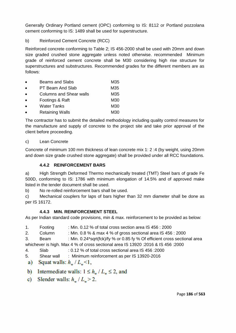
Page 186 of 563
Generally Ordinary Portland cement (OPC) conforming to IS: 8112 or Portland pozzolana
cement conforming to IS: 1489 shall be used for superstructure.
b) Reinforced Cement Concrete (RCC)
Reinforced concrete conforming to Table 2; IS 456-2000 shall be used with 20mm and down
size graded crushed stone aggregate unless noted otherwise. recommended Minimum
grade of reinforced cement concrete shall be M30 considering high rise structure for
superstructures and substructures. Recommended grades for the different members are as
follows:
Beams and Slabs M35
PT Beam And Slab M35
Columns and Shear walls M35
Footings & Raft M30
Water Tanks M30
Retaining Walls M30
The contractor has to submit the detailed methodology including quality control measures for
the manufacture and supply of concrete to the project site and take prior approval of the
client before proceeding.
c) Lean Concrete
Concrete of minimum 100 mm thickness of lean concrete mix 1: 2 :4 (by weight, using 20mm
and down size grade crushed stone aggregate) shall be provided under all RCC foundations.
4.4.2 REINFORCEMENT BARS
a) High Strength Deformed Thermo mechanically treated (TMT) Steel bars of grade Fe
500D, conforming to IS: 1786 with minimum elongation of 14.5% and of approved make
listed in the tender document shall be used.
b) No re-rolled reinforcement bars shall be used.
c) Mechanical couplers for laps of bars higher than 32 mm diameter shall be done as
per IS 16172.
4.4.3 MIN. REINFORCEMENT STEEL
As per Indian standard code provisions, min & max. reinforcement to be provided as below:
1. Footing : Min. 0.12 % of total cross section area IS 456 : 2000
2. Column : Min. 0.8 % & max 4 % of gross sectional area IS 456 : 2000
3. Beam : Min. 0.24*sqrt(fck)/fy % or 0.85 fy % Of efficient cross sectional area
whichever is high. Max 4 % of cross sectional area IS 13920 :2016 & IS 456 :2000
4. Slab : 0.12 % of total cross sectional area IS 456 :2000
5. Shear wall : Minimum reinforcement as per IS 13920-2016
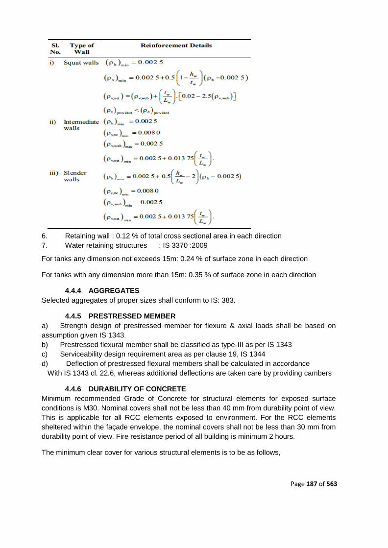
Page 187 of 563
6. Retaining wall : 0.12 % of total cross sectional area in each direction
7. Water retaining structures : IS 3370 :2009
For tanks any dimension not exceeds 15m: 0.24 % of surface zone in each direction
For tanks with any dimension more than 15m: 0.35 % of surface zone in each direction
4.4.4 AGGREGATES
Selected aggregates of proper sizes shall conform to IS: 383.
4.4.5 PRESTRESSED MEMBER
a) Strength design of prestressed member for flexure & axial loads shall be based on
assumption given IS 1343.
b) Prestressed flexural member shall be classified as type-III as per IS 1343
c) Serviceability design requirement area as per clause 19, IS 1344
d) Deflection of prestressed flexural members shall be calculated in accordance
With IS 1343 cl. 22.6, whereas additional deflections are taken care by providing cambers
4.4.6 DURABILITY OF CONCRETE
Minimum recommended Grade of Concrete for structural elements for exposed surface
conditions is M30. Nominal covers shall not be less than 40 mm from durability point of view.
This is applicable for all RCC elements exposed to environment. For the RCC elements
sheltered within the façade envelope, the nominal covers shall not be less than 30 mm from
durability point of view. Fire resistance period of all building is minimum 2 hours.
The minimum clear cover for various structural elements is to be as follows,

Page 188 of 563
Table 4.1 Minimum Clear cover for various structural elements
1 Slab (simply supported) : 35mm
(continuous) : 25mm
2 Beams (Roof & floor) (simply supported) : 40mm
(continuous) : 30mm
3 Tie beam Tie beam : 40mm
4 Columns/Pedestals (Main R/F) : 40mm
5 Foundation (Bottom) : 50mm
(Top and Side) : 50mm
6 RCC wall RCC wall : 40mm
7 Water retaining structures : 50mm
4.4.7 RCC LINTEL
RCC lintel and sill band shall be provided for all masonry in continuous length.
4.4.8 MINIMUM / MAXIMUM THICKNESS OF STRUCTURAL CONCRETE
ELEMENTS
Beam width 200 mm / 750 mm.
Floor slabs, Roof slabs 125 mm / 350 mm.
Columns 300 mm / 1200 mm.
Circular Column (Diameter) 450 mm / 1500 mm.
Wall thickness (0.4%≤p≤1.0%) 200 mm / 500 mm.
The following minimum / maximum thickness shall also be followed:
Ground floor slab (non-suspended) 125mm / 300 mm.
Footings (All types including raft foundations) 300 mm /as required.
Liquid retaining structures 200 mm / 400 mm.
Basement walls 200 mm / 400 mm.
Parapets, Chajjas 125 mm / 200 mm.
Cable/ Pipe trenches, under-ground pit 125 mm / 250 mm.
Precast Trench Cover/ Floor Slab 100 mm / 250 mm.
4.4.9 CONSTRUCTION JOINT
Construction joints, pour strips and shrinkage strips to be planned by the contractor, at
design stage (as per IS code: 3414) itself and only be used in locations pre-approved by
consultants. All construction joints of water retaining structures in RCC shall be made water
tight using approved make water stops. Water stops shall be provided in all construction
joints below ground level in addition to any joint which may be detailed on the drawing.
4.4.10 EXPANSION JOINT
To relieve the structure from temperature stresses, expansion joints are provided at several
locations as per the requirements. As per BIS code requirement expansion joints are
proposed if the length of the structure exceeds 45m. Depending upon geometry of building
and for lateral load resisting system expansion joint may be at a distance larger than that
recommended by IS codes. Gap for the expansion / separation joint shall be provided as per

Page 189 of 563
the provisions mentioned in IS 1893 part IV. The gap in between will be later filled by
approved board & sealant with proper treatment. There shall be a dual column system with
combined footing at the expansion joint locations.
4.4.11 PERMISSIBLE DEFLECTIONS
Permissible deflections shall be as per IS: 456 clause 23.2. Total deflection of various
structural members shall be calculated as per ANNEX C of IS 456. Provisions of IS 1893
and IS 875 shall be followed for lateral deformations.
1. The final vertical deflection due to all loads including the effects of temperature,
creep and shrinkage and measured from the as-cast level of the supports of floors, roofs and
all other horizontal members should not normally exceed span/250.
2. The part deflection including the effects of temperature, creep and shrinkage should
not normally exceed span/350 or 20 mm whichever is less.
3. Under wind load, the lateral sway at the top of building should not exceed height/500.
4.4.12 STOREY DRIFT
Storey Drift shall be check for not exceeding 0.004 times the storey height as per IS 1893-
2016 clause 7.11.1.
4.4.13 SOFT STOREY
Soft story effect shall be check as per IS 1893-2016.
4.4.14 TORSION EFFECT
Resulting torsion effect due to eccentricity between centre of mass and centre of rigidity shall
be considered in design as per IS 1893-2016 clause 7.8. Also please check the analysis of
building to suffice criteria as per table 5 of IS 1893-2016 – for torsional irregularity (Torsion in
first two modes of oscillation shall not be allowed).
4.4.15 FACTOR OF SAFETY
The factor of safety against overturning and sliding and flotation shall be as follows:
a) Against Overturning : 1.4 as per clause 20.1 IS 456:2000
b) Against sliding : 1.4 as per clause 20.2 IS 456:2000
c) Against flotation : 1.2 as per clause 7.2 IS 3370 (part-1):2009
4.4.16 CRACK WIDTH
Various structural members shall be designed for crack width mentioned as below as per
clause no. 35.3.2, IS 456:2000 & clause no. 4.4.1.2, IS 3370(Part-2):2009.
• For structural members exposure to serve exposure condition = 0.1mm
• For water retaining structures = 0.2 mm
• For members exposed to soil or ground water = 0.2 mm
• All other structural members = 0.3 mm
4.4.17 DESIGN LOADS
The various structures/ buildings for this project shall be designed for the following loads and
also effects due to shrinkage, creep, temperature, etc, where applicable.

Page 190 of 563
4.4.17.1 Dead Load
The dead loads are calculated on the basis of unit weights of materials given in IS: 875 (Part
1). The dead load considered in the structural design shall consist of the full weight of all
known fixed structural and architectural elements. The weight of fixed service equipment
excluding their contents such as heating, ventilating and air conditioning systems and the
weight of all process equipment including all fixtures (conduit, cable tray, ductwork, etc.
permanently attached to the structure) and attached piping but excluding their contents shall
be considered in dead load. The data provided by the project architect and other service
consultants will be used for the specific materials/ equipments.
Unless otherwise specified; the unit weight of materials will be used as follows.
Table 4.2 Unit Weight of Materials
Reinforced concrete 25.00 kN/m3
Plain concrete 24.00 kN/m3
Light weight concrete 12.00 kN/m3
Concrete block work 18.00 kN/m3
Brickwork 20.00 kN/m3
Autoclaved Aerated Concrete Blocks 8.00 kN/m3
Stone cladding 25.00 kN/m3
Floor finishes 20.00 kN/m3
Glass 23.50 kN/m3
Structural steel 78.50 kN/m3
Water 09.81 kN/m3
Dry Soil 16.00 kN/m3
Saturated Soil (Garden load with roots) 21.00 kN/m3
Typical dead loads considered in the design are as follows:
Self weight of slabs, beams, columns & walls - As per sectional sizes of the members.
Additional dead loads
floor finishes for all floors except roof 1.5 kN/m2
false ceiling and utility load for all floors 0.5 kN/m2
Light weight partition wall load for Shop 3.0KN/m2
Light weight partition wall load for office 1.5KN/m2
Water Proofing at Terrace ( BBC waterproofing) 3.0 kN/m2
Escalator loads to be taken for design as per approved vendor data and necessary provision
in structural framing to be made for supporting arrangement of escalator.
The effects due to provision of sunken slabs in floor and terrace gardens shall be considered
as per Architectural or MEP drawings.

Page 191 of 563
4.4.17.2 Live Load
All the live loads shall be as per IS: 875 (Part 2). In general, following loads reproduced from
the code by the use/ occupancy of a building or structure shall be the minimum considered in
the designs.
Table 4.3 Live Load Details
Loading Area Load Intensity (KN/m2)
Shop and Office Area 4.00
Cafeteria 4.00
Balconies, Corridors, passages, lobbies
and staircases including fire escapes –
as per the floor serviced (excluding
stores)
4.00
Toilets and Bath Rooms 2.00
Accessible Roof 1.50
Inaccessible Roof 0.75
Terrace Roof Slab (with Solar Panel) 3.00
Multipurpose Hall 5.00
Storage Area 5.00
Play area, Paved Area, Landscape/
Lawn
5.00
Pantry 3.00
Lobby, Footpath, Utility Area 5.00
Swimming Pool Area 5.00
Car Parking Area/Ramp 5.00
Planter Area 10.00
Electrical Meter room 5.00
Mechanical room 5.00
Pump house 5.00
DG room 10.00
In addition to the live/imposed loads specified above, loads by dynamic effect of machinery
shall be considered. The loads due to the machinery and equipment shall be as specified by
the manufacturer and if it exceeds to above then actual loads shall be considered. Resonant
conditions shall be avoided by suitably proportioning the supporting structural members.

Page 192 of 563
4.4.17.3 Wind Load (Wl)
All buildings and structures shall be designed to withstand the forces of wind pressure,
assumed in any horizontal direction with no allowance for the effect of shielding by other
adjacent structures, in accordance with the appropriate provisions of IS: 875 (Part 3).
Basic Wind speed
for Bhopal:
Vb = 39 m/sec
Design Wind Speed
at any height :
Vz = K1 K2 K3 K4 Vb m/sec Clause 5.3
Where; K1 = Probability factor = 1.0
K2 = Terrain height & structure size factor
For Category 1 and Class of structures - Class C,
Values of Table 2 of IS: 875-Part 3 to be referred.
K3 = Topography factor = 1.0
K3 = Importance factor for Cyclonic Region = 1.0
Design Wind Pressure at
any height :
Pz = 0.6 x Vz2 N/m2 Clause 7.2
Based on the above wind pressure and exposure of the building, further load calculations will
be carried out with respect to profile of building as per IS: 875 (Part 3).
4.4.17.4 Seismic Load (SL)
All buildings, structures, foundations etc shall be designed for Seismic Zone - II in
accordance with IS: 1893 (part-1)-2016, to resist the effects of earthquakes. Inertial loads
due to earthquake shall be applied at the mass centre of each level. These forces would be
either calculated manually or auto generated by using the Auto Seismic Loads function of
the software used for analysis. For all structures, the seismic base shall be considered at
foundation level. All buildings shall have special moment resisting frames with or without
shear walls to resist lateral force due to earthquake as recommended for Zone 2. Seismic
Coefficient Method for Static Analysis & Response Spectrum Method for Dynamic Analysis
will be used depending on the building height and geometric configuration as specified in
clause 7.7.2 of IS 1893 (part-1). Appropriate actions would be taken as recommended by IS
code for Structural irregularities. Appropriate percentage of imposed load will be considered
in seismic weight calculations as per table 10 of IS 1893 (part-1). As per table 1 of IS 1893,
allowable bearing pressure can be increased by 50 percent for raft foundations in type I
bearing strata respectively for seismic cases (if found governing).

Page 193 of 563
SEISMIC PARAMETERS
Seismic design forces shall be determined based upon the following parameters.
Table 4.4 Parameters for designing Seismic force
Item Value Reference
Zone Factor (z): 0.1 (Low) Table 3 (IS 1893-Part
1)
Importance Factor (I): 1.2
Table 8 (IS 1893-Part
1)
Response Reduction Factor (R): 3.0
Table 9 (IS 1893-Part
1)
Fundamental Natural Period
(Ta)
0.09 h / √d
(with brick infill
Panel)
Clause No: 7.6.2
IS: 1893 (Part 1).
0.075 h0.75
(without brick infill
Panel)
Clause No: 7.6.2
IS: 1893 (Part 1).
Damping 5% Clause No: 7.2.4
Average Response Acceleration
Coefficient (Sa/g):
For hard soil sites
1+15T 0.00 < T <
0.10
2.5 0.10 < T <
0.40
1.00 / T 0.40 < T <
4.00
0.25 T >
4.00
Fig. 2 Response
Spectra for Rock &
Soil Sites for 5
percent damping.
Design Spectrum
The design horizontal seismic
coefficient (Ah)
Z I Sa Clause No: 6.4.2
–
IS: 1893 (Part 1). 2 R g
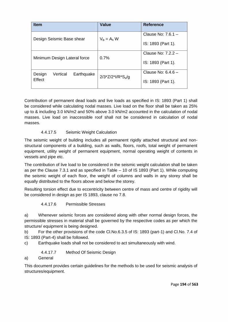
Page 194 of 563
Item Value Reference
Design Seismic Base shear VB = Ah W Clause No: 7.6.1 –
IS: 1893 (Part 1).
Minimum Design Lateral force 0.7% Clause No: 7.2.2 –
IS: 1893 (Part 1).
Design Vertical Earthquake
Effect 2/3*Z/2*I/R*Sa/g
Clause No: 6.4.6 –
IS: 1893 (Part 1).
Contribution of permanent dead loads and live loads as specified in IS: 1893 (Part 1) shall
be considered while calculating nodal masses. Live load on the floor shall be taken as 25%
up to & including 3.0 kN/m2 and 50% above 3.0 kN/m2 accounted in the calculation of nodal
masses. Live load on inaccessible roof shall not be considered in calculation of nodal
masses.
4.4.17.5 Seismic Weight Calculation
The seismic weight of building includes all permanent rigidly attached structural and non-
structural components of a building, such as walls, floors, roofs, total weight of permanent
equipment, utility weight of permanent equipment, normal operating weight of contents in
vessels and pipe etc.
The contribution of live load to be considered in the seismic weight calculation shall be taken
as per the Clause 7.3.1 and as specified in Table – 10 of IS 1893 (Part 1). While computing
the seismic weight of each floor, the weight of columns and walls in any storey shall be
equally distributed to the floors above and below the storey.
Resulting torsion effect due to eccentricity between centre of mass and centre of rigidity will
be considered in design as per IS 1893, clause no 7.8.
4.4.17.6 Permissible Stresses
a) Whenever seismic forces are considered along with other normal design forces, the
permissible stresses in material shall be governed by the respective codes as per which the
structure/ equipment is being designed.
b) For the other provisions of the code Cl.No.6.3.5 of IS: 1893 (part-1) and Cl.No. 7.4 of
IS: 1893 (Part-4) shall be followed.
c) Earthquake loads shall not be considered to act simultaneously with wind.
4.4.17.7 Method Of Seismic Design
a) General
This document provides certain guidelines for the methods to be used for seismic analysis of
structures/equipment.

Page 195 of 563
b) Method of Analysis
Dynamic Analysis by response spectrum method shall be used to analysis structures for
earthquake forces. For all Structures recommendations as per IS: 1893-1-2016 shall be
followed.
4.4.17.8 Ductile Detailing
The ductility details of reinforced concrete members shall be provided as per the provisions
of IS: 13920-2016 to avoid premature failure during earthquake.
4.4.18 IMPACT LOADS
a) All structural framing and concrete foundations subject to vibration, impact, impulse,
shock, etc., shall be designed to withstand the generated forces within the limits of
acceptable stress, deflection, and/or amplitude of vibration.
b) All structures supporting reciprocating equipment or rotating equipment with
excessive imbalance shall be analyzed for both strength and response.
c) All structures supporting moving or stationary equipment shall be designed for static
loads plus an appropriate impact factor as defined by the equipment manufacturer, IS: 875,
IS: 2974.
4.4.18.1 Wheel Load
For any structure or pipeline below roads, IRC Class of loading for which the road has been
actually designed will be considered.
4.4.18.2 Surcharge Load
Minimum surcharge of 10KN/m2 and as per IRC whichever is higher shall be considered for
design of all underground structures to take in to account the construction load and vehicular
traffic in the vicinity of structure. The soil parameters and ground water table will be
considered as per soil investigation report.
4.4.18.3 Earth Pressure
Earth pressure for walls of basement/ tanks etc. with propped support condition will be
calculated using coefficient of earth pressure at-rest. Earth pressure for cantilever walls like
cable trenches will be calculated based on active earth pressure. Unit weight of soil shall be
as per section 8.1. Other soil parameters such as cohesion and angle of internal friction shall
be considered as per soil investigation report.
4.4.18.4 Hydrostatic Pressure
If envisaged, the ground water load shall be applied on the substructure as super imposed
dead load in addition to the earth pressure. The dry density of soil shall be considered in this
combination.
4.4.18.5 Construction Loads
Loads produced by the materials of construction plus the equipment required to construct
the facility (crane loads, rigging loads, earth moving equipment, etc.) as applicable shall be
considered. When the sequencing of construction will not permit the lateral force resisting
system of the structure to be constructed first, the engineer shall make provisions for
temporary lateral bracing and clearly identify these requirements on the design drawings and

Page 196 of 563
contract documents. The Contractor shall coordinate the sequence of building erection and
the types and quantity of construction equipment to be used.
Any other loads like those of services; storage etc has to be obtained from time to time from
the relevant consultants and is to be incorporated. The top slab of the lift shaft to be
designed for lift loads as obtained from the manufacturer.
4.4.18.6 Temperature Loads
Yearly Average Maximum temperature: (+) 32 °C
Yearly Average Minimum temperature: (+) 19 °C
The coefficient of Thermal Expansion for
Reinforcing steel and Normal Weight Concrete: 11.7 x 10⁻⁶ / °C.
To consider the effects of shrinkage on structure, a shrinkage strain of 0.003 is to be taken
4.4.18.7 Load Combinations
Each element of a building or structure shall be provided with sufficient strength to resist the
most critical effects resulting from the following combination of loads.
Load cases and load combination shall be as follow:
a) Load Cases
1. DL : Dead Load
2. LL : Live Load
3. SDL : Super Dead Load
4. EQX : Earthquake in X-direction
5. EQY : Earthquake in Y-direction
6. EQZ : Earthquake in Z-direction
7. Spec-X : Spectra in X-direction
8. Spec-Y : Spectra in Y-direction
9. Spec-Y : Spectra in Z-direction
10. WLx : Wind load in X-direction
11. WLy : Wind load in Y-direction

Page 197 of 563
12. TL : Temperature load ( If applicable )
13. CL : Construction load ( If applicable )
(X and Y directions are mutually orthogonal in plan area, Z Direction is vertical to define the
direction of seismic forces with reference to building)
b) Load Combinations
The following Load Combinations have been considered for the analysis.
Table 4.5 Load Combinations
SR NO
LOAD COMBINATION FOR SIZING OF FOOTINGS / CHCEKING OF SBC
LOAD COMBINATION FOR DESIGN OF FOOTINGS & SUPERSTRUCTURE
1 (DL+SDL+LL) 1.5*(DL+SDL+LL)
2 (DL+SDL+WLx) 1.5*(DL+SDL+WLx)
3 (DL+SDL-WLx) 1.5*(DL+SDL-WLx)
4 (DL+SDL+WLy) 1.5*(DL+SDL+WLy)
5 (DL+SDL-WLy) 1.5*(DL+SDL-WLy)
6 (DL+SDL+LL+WLx) 1.2*(DL+SDL+LL+WLx)
7 (DL+SDL+LL-WLx) 1.2*(DL+SDL+LL-WLx)
8 (DL+SDL+LL+WLy) 1.2*(DL+SDL+LL+WLy)
9 (DL+SDL+LL-WLy) 1.2*(DL+SDL+LL-WLy)
10 (DL+SDL+EQX+0.3EQY
+0.3EQZ) 1.5*(DL+SDL+EQX+0.3EQY+0.3EQZ)
11 (DL+SDL+EQX-0.3EQY
+0.3EQZ) 1.5*(DL+SDL+EQX-0.3EQY+0.3EQZ)
12 (DL+SDL+EQX+0.3EQY
-0.3EQZ) 1.5*(DL+SDL+EQX+0.3EQY-0.3EQZ)
13 (DL+SDL+EQX-0.3EQY
-0.3EQZ) 1.5*(DL+SDL+EQX-0.3EQY-0.3EQZ)
14 (DL+SDL-EQX+0.3EQY
+0.3EQZ) 1.5*(DL+SDL-EQX+0.3EQY+0.3EQZ)
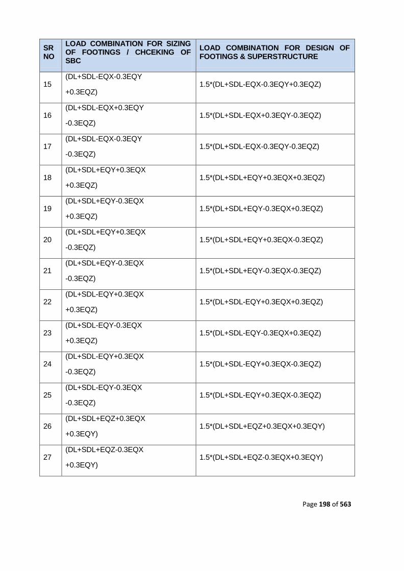
Page 198 of 563
SR NO
LOAD COMBINATION FOR SIZING OF FOOTINGS / CHCEKING OF SBC
LOAD COMBINATION FOR DESIGN OF FOOTINGS & SUPERSTRUCTURE
15 (DL+SDL-EQX-0.3EQY
+0.3EQZ) 1.5*(DL+SDL-EQX-0.3EQY+0.3EQZ)
16 (DL+SDL-EQX+0.3EQY
-0.3EQZ) 1.5*(DL+SDL-EQX+0.3EQY-0.3EQZ)
17 (DL+SDL-EQX-0.3EQY
-0.3EQZ) 1.5*(DL+SDL-EQX-0.3EQY-0.3EQZ)
18 (DL+SDL+EQY+0.3EQX
+0.3EQZ) 1.5*(DL+SDL+EQY+0.3EQX+0.3EQZ)
19 (DL+SDL+EQY-0.3EQX
+0.3EQZ) 1.5*(DL+SDL+EQY-0.3EQX+0.3EQZ)
20 (DL+SDL+EQY+0.3EQX
-0.3EQZ) 1.5*(DL+SDL+EQY+0.3EQX-0.3EQZ)
21 (DL+SDL+EQY-0.3EQX
-0.3EQZ) 1.5*(DL+SDL+EQY-0.3EQX-0.3EQZ)
22 (DL+SDL-EQY+0.3EQX
+0.3EQZ) 1.5*(DL+SDL-EQY+0.3EQX+0.3EQZ)
23 (DL+SDL-EQY-0.3EQX
+0.3EQZ) 1.5*(DL+SDL-EQY-0.3EQX+0.3EQZ)
24 (DL+SDL-EQY+0.3EQX
-0.3EQZ) 1.5*(DL+SDL-EQY+0.3EQX-0.3EQZ)
25 (DL+SDL-EQY-0.3EQX
-0.3EQZ) 1.5*(DL+SDL-EQY+0.3EQX-0.3EQZ)
26 (DL+SDL+EQZ+0.3EQX
+0.3EQY) 1.5*(DL+SDL+EQZ+0.3EQX+0.3EQY)
27 (DL+SDL+EQZ-0.3EQX
+0.3EQY) 1.5*(DL+SDL+EQZ-0.3EQX+0.3EQY)

Page 199 of 563
SR NO
LOAD COMBINATION FOR SIZING OF FOOTINGS / CHCEKING OF SBC
LOAD COMBINATION FOR DESIGN OF FOOTINGS & SUPERSTRUCTURE
28 (DL+SDL+EQZ+0.3EQX
-0.3EQY) 1.5*(DL+SDL+EQZ+0.3EQX-0.3EQY)
29 (DL+SDL+EQZ-0.3EQX
-0.3EQY) 1.5*(DL+SDL+EQZ-0.3EQX-0.3EQY)
30 (DL+SDL-EQZ+0.3EQX
+0.3EQY) 1.5*(DL+SDL-EQZ+0.3EQX+0.3EQY)
31 (DL+SDL-EQZ-0.3EQX
+0.3EQY) 1.5*(DL+SDL-EQZ-0.3EQX+0.3EQY)
32 (DL+SDL-EQZ+0.3EQX
-0.3EQY) 1.5*(DL+SDL-EQZ+0.3EQX-0.3EQY)
33 (DL+SDL-EQZ-0.3EQX
-0.3EQY) 1.5*(DL+SDL-EQZ+0.3EQX-0.3EQY)
34 (DL+SDL+LL+EQX+0.3EQY
+0.3EQZ) 1.2*(DL+SDL+LL+EQX+0.3EQY+0.3EQZ)
35 (DL+SDL+LL+EQX-0.3EQY
+0.3EQZ) 1.2*(DL+SDL+LL+EQX-0.3EQY+0.3EQZ)
36 (DL+SDL+LL+EQX+0.3EQY
-0.3EQZ) 1.2*(DL+SDL+LL+EQX+0.3EQY-0.3EQZ)
37 (DL+SDL+LL+EQX-0.3EQY
-0.3EQZ) 1.2*(DL+SDL+LL+EQX-0.3EQY-0.3EQZ)
38 (DL+SDL+LL-EQX+0.3EQY
+0.3EQZ) 1.2*(DL+SDL+LL-EQX+0.3EQY+0.3EQZ)
39 (DL+SDL+LL-EQX-0.3EQY
+0.3EQZ) 1.2*(DL+SDL+LL-EQX-0.3EQY+0.3EQZ)
40 (DL+SDL+LL-EQX+0.3EQY
-0.3EQZ) 1.2*(DL+SDL+LL-EQX+0.3EQY-0.3EQZ)

Page 200 of 563
SR NO
LOAD COMBINATION FOR SIZING OF FOOTINGS / CHCEKING OF SBC
LOAD COMBINATION FOR DESIGN OF FOOTINGS & SUPERSTRUCTURE
41 (DL+SDL+LL-EQX-0.3EQY
-0.3EQZ) 1.2*(DL+SDL+LL-EQX-0.3EQY-0.3EQZ)
42 (DL+SDL+LL+EQY+0.3EQX
+0.3EQZ) 1.2*(DL+SDL+LL+EQY+0.3EQX+0.3EQZ)
43 (DL+SDL+LL+EQY-0.3EQX
+0.3EQZ) 1.2*(DL+SDL+LL+EQY-0.3EQX+0.3EQZ)
44 (DL+SDL+LL+EQY+0.3EQX
-0.3EQZ) 1.2*(DL+SDL+LL+EQY+0.3EQX-0.3EQZ)
45 (DL+SDL+LL+EQY-0.3EQX
-0.3EQZ) 1.2*(DL+SDL+LL+EQY-0.3EQX-0.3EQZ)
46 (DL+SDL+LL-EQY+0.3EQX
+0.3EQZ) 1.2*(DL+SDL+LL-EQY+0.3EQX+0.3EQZ)
47 (DL+SDL+LL-EQY-0.3EQX
+0.3EQZ) 1.2*(DL+SDL+LL-EQY-0.3EQX+0.3EQZ)
48 (DL+SDL+LL-EQY+0.3EQX
-0.3EQZ) 1.2*(DL+SDL+LL-EQY+0.3EQX-0.3EQZ)
49 (DL+SDL+LL-EQY-0.3EQX
-0.3EQZ) 1.2*(DL+SDL+LL-EQY-0.3EQX-0.3EQZ)
50 (DL+SDL+LL+EQZ+0.3EQX
+0.3EQY) 1.2*(DL+SDL+LL+EQY+0.3EQX+0.3EQY)
51 (DL+SDL+LL+EQZ-0.3EQX
+0.3EQY) 1.2*(DL+SDL+LL+EQY-0.3EQX+0.3EQY)
52 (DL+SDL+LL+EQZ+0.3EQX
-0.3EQY) 1.2*(DL+SDL+LL+EQY+0.3EQX-0.3EQY)
53 (DL+SDL+LL+EQZ-0.3EQX
-0.3EQY) 1.2*(DL+SDL+LL+EQY-0.3EQX-0.3EQY)

Page 201 of 563
SR NO
LOAD COMBINATION FOR SIZING OF FOOTINGS / CHCEKING OF SBC
LOAD COMBINATION FOR DESIGN OF FOOTINGS & SUPERSTRUCTURE
54 (DL+SDL+LL-EQZ+0.3EQX
+0.3EQY) 1.2*(DL+SDL+LL-EQY+0.3EQX+0.3EQY)
55 (DL+SDL+LL-EQZ-0.3EQX
+0.3EQY) 1.2*(DL+SDL+LL-EQY-0.3EQX+0.3EQY)
56 (DL+SDL+LL-EQZ+0.3EQX
-0.3EQY) 1.2*(DL+SDL+LL-EQY+0.3EQX-0.3EQY)
57 (DL+SDL+LL-EQZ-0.3EQX
-0.3EQY) 1.2*(DL+SDL+LL-EQZ-0.3EQX-0.3EQY)
58 (0.9*DL+0.9*SDL+1*EQX+1*EQY
+1*EQZ)
(0.9*DL+0.9*SDL+1.5*EQX+1.5*EQY
+1.5*EQZ)
59 (0.9*DL+0.9*SDL+1*EQX-1*EQY
+1*EQZ)
(0.9*DL+0.9*SDL+1.5*EQX-1.5*EQY
+1.5*EQZ)
60 (0.9*DL+0.9*SDL+1*EQX+1*EQY
-1*EQZ)
(0.9*DL+0.9*SDL+1.5*EQX+1.5*EQY
-1.5*EQZ)
61 (0.9*DL+0.9*SDL+1*EQX-1*EQY
-1*EQZ)
(0.9*DL+0.9*SDL+1.5*EQX-1.5*EQY
-1.5*EQZ)
62 (0.9*DL+0.9*SDL-1*EQX+1*EQY
+1*EQZ)
(0.9*DL+0.9*SDL-1.5*EQX+1.5*EQY
+1.5*EQZ)
63 (0.9*DL+0.9*SDL-1*EQX-1*EQY
+1*EQZ)
(0.9*DL+0.9*SDL-1.5*EQX-1.5*EQY
+1.5*EQZ)
64 (0.9*DL+0.9*SDL-1*EQX+1*EQY
-1*EQZ)
(0.9*DL+0.9*SDL-1.5*EQX+1.5*EQY
-1.5*EQZ)
65 (0.9*DL+0.9*SDL-1*EQX-1*EQY
-1*EQZ)
(0.9*DL+0.9*SDL-1.5*EQX-1.5*EQY
-1.5*EQZ)
66 (0.9*DL+0.9*SDL+1*EQY+1*EQX
+1*EQZ)
(0.9*DL+0.9*SDL+1.5*EQY+1.5*EQX
+1.5*EQZ)

Page 202 of 563
SR NO
LOAD COMBINATION FOR SIZING OF FOOTINGS / CHCEKING OF SBC
LOAD COMBINATION FOR DESIGN OF FOOTINGS & SUPERSTRUCTURE
67 (0.9*DL+0.9*SDL+1*EQY-1*EQX
+1*EQZ)
(0.9*DL+0.9*SDL+1.5*EQY-1.5*EQX
+1.5*EQZ)
68 (0.9*DL+0.9*SDL+1*EQY+1*EQX
-1*EQZ)
(0.9*DL+0.9*SDL+1.5*EQY+1.5*EQX
-1.5*EQZ)
69 (0.9*DL+0.9*SDL+1*EQY-1*EQX
-1*EQZ)
(0.9*DL+0.9*SDL+1.5*EQY-1.5*EQX
-1.5*EQZ)
70 (0.9*DL+0.9*SDL-1*EQY+1*EQX
+1*EQZ)
(0.9*DL+0.9*SDL-1.5*EQY+1.5*EQX
+1.5*EQZ)
71 (0.9*DL+0.9*SDL-1*EQY-1*EQX
+1*EQZ)
(0.9*DL+0.9*SDL-1.5*EQY-1.5*EQX
+1.5*EQZ)
72 (0.9*DL+0.9*SDL-1*EQY+1*EQX
-1*EQZ)
(0.9*DL+0.9*SDL-1.5*EQY+1.5*EQX
-1.5*EQZ)
73 (0.9*DL+0.9*SDL-1*EQY-1*EQX
-1*EQZ)
(0.9*DL+0.9*SDL-1.5*EQY-1.5*EQX
-1.5*EQZ)
74 (0.9*DL+0.9*SDL+1*EQZ+1*EQX
+1*EQY)
(0.9*DL+0.9*SDL+1.5*EQZ+1.5*EQX
+1.5*EQY)
75 (0.9*DL+0.9*SDL+1*EQZ-1*EQX
+1*EQY)
(0.9*DL+0.9*SDL+1.5*EQZ-1.5*EQX
+1.5*EQY)
76 (0.9*DL+0.9*SDL+1*EQZ+1*EQX
-1*EQY)
(0.9*DL+0.9*SDL+1.5*EQZ+1.5*EQX
-1.5*EQY)
77 (0.9*DL+0.9*SDL+1*EQZ-1*EQX
-1*EQY)
(0.9*DL+0.9*SDL+1.5*EQZ-1.5*EQX
-1.5*EQY)
78 (0.9*DL+0.9*SDL-1*EQZ+1*EQX
+1*EQY)
(0.9*DL+0.9*SDL-1.5*EQZ+1.5*EQX
+1.5*EQY)
79 (0.9*DL+0.9*SDL-1*EQZ-1*EQX
+1*EQY)
(0.9*DL+0.9*SDL-1.5*EQZ-1.5*EQX
+1.5*EQY)

Page 203 of 563
SR NO
LOAD COMBINATION FOR SIZING OF FOOTINGS / CHCEKING OF SBC
LOAD COMBINATION FOR DESIGN OF FOOTINGS & SUPERSTRUCTURE
80 (0.9*DL+0.9*SDL-1*EQZ+1*EQX
-1*EQY)
(0.9*DL+0.9*SDL-1.5*EQZ+1.5*EQX
-1.5*EQY)
81 (0.9*DL+0.9*SDL-1*EQZ-1*EQX
-1*EQY)
(0.9*DL+0.9*SDL-1.5*EQZ-1.5*EQX
-1.5*EQY)
82 (DL+SDL+SPECX+0.3SPECY
+0.3SPECZ)
1.5*(DL+SDL+SPECX+0.3SPECY
+0.3SPECZ)
83 (DL+SDL+SPECX-0.3SPECY
+0.3SPECZ)
1.5*(DL+SDL+SPECX-0.3SPECY
+0.3SPECZ)
84 (DL+SDL+SPECX+0.3SPECY
-0.3SPECZ)
1.5*(DL+SDL+SPECX+0.3SPECY
-0.3SPECZ)
85 (DL+SDL+SPECX-0.3SPECY
-0.3SPECZ)
1.5*(DL+SDL+SPECX-0.3SPECY
-0.3SPECZ)
86 (DL+SDL-SPECX+0.3SPECY
+0.3SPECZ)
1.5*(DL+SDL-SPECX+0.3SPECY
+0.3SPECZ)
87 (DL+SDL-SPECX-0.3SPECY
+0.3SPECZ)
1.5*(DL+SDL-SPECX-0.3SPECY
+0.3SPECZ)
88 (DL+SDL-SPECX+0.3SPECY
-0.3SPECZ)
1.5*(DL+SDL-SPECX+0.3SPECY
-0.3SPECZ)
89 (DL+SDL-SPECX-0.3SPECY
-0.3SPECZ)
1.5*(DL+SDL-SPECX-0.3SPECY
-0.3SPECZ)
90 (DL+SDL+SPECY+0.3SPECX
+0.3SPECZ)
1.5*(DL+SDL+SPECY+0.3SPECX
+0.3SPECZ)
91 (DL+SDL+SPECY-0.3SPECX
+0.3SPECZ)
1.5*(DL+SDL+SPECY-0.3SPECX
+0.3SPECZ)
92 (DL+SDL+SPECY+0.3SPECX
-0.3SPECZ)
1.5*(DL+SDL+SPECY+0.3SPECX
-0.3SPECZ)

Page 204 of 563
SR NO
LOAD COMBINATION FOR SIZING OF FOOTINGS / CHCEKING OF SBC
LOAD COMBINATION FOR DESIGN OF FOOTINGS & SUPERSTRUCTURE
93 (DL+SDL+SPECY-0.3SPECX
-0.3SPECZ)
1.5*(DL+SDL+SPECY-0.3SPECX
-0.3SPECZ)
94 (DL+SDL-SPECY+0.3SPECX
+0.3SPECZ)
1.5*(DL+SDL-SPECY+0.3SPECX
+0.3SPECZ)
95 (DL+SDL-SPECY-0.3SPECX
+0.3SPECZ)
1.5*(DL+SDL-SPECY-0.3SPECX
+0.3SPECZ)
96 (DL+SDL-SPECY+0.3SPECX
-0.3SPECZ)
1.5*(DL+SDL-SPECY+0.3SPECX
-0.3SPECZ)
97 (DL+SDL-SPECY-0.3SPECX
-0.3SPECZ)
1.5*(DL+SDL-SPECY+0.3SPECX
-0.3SPECZ)
98 (DL+SDL+SPECZ+0.3SPECX
+0.3SPECY)
1.5*(DL+SDL+SPECZ+0.3SPECX
+0.3SPECY)
99 (DL+SDL+SPECZ-0.3SPECX
+0.3SPECY)
1.5*(DL+SDL+SPECZ-0.3SPECX
+0.3SPECY)
100 (DL+SDL+SPECZ+0.3SPECX
-0.3SPECY)
1.5*(DL+SDL+SPECZ+0.3SPECX
-0.3SPECY)
101 (DL+SDL+SPECZ-0.3SPECX
-0.3SPECY)
1.5*(DL+SDL+SPECZ-0.3SPECX
-0.3SPECY)
102 (DL+SDL-SPECZ+0.3SPECX
+0.3SPECY)
1.5*(DL+SDL-SPECZ+0.3SPECX
+0.3SPECY)
103 (DL+SDL-SPECZ-0.3SPECX
+0.3SPECY)
1.5*(DL+SDL-SPECZ-0.3SPECX
+0.3SPECY)
104 (DL+SDL-SPECZ+0.3SPECX
-0.3SPECY)
1.5*(DL+SDL-SPECZ+0.3SPECX
-0.3SPECY)
105 (DL+SDL-SPECZ-0.3SPECX
-0.3SPECY)
1.5*(DL+SDL-SPECZ+0.3SPECX
-0.3SPECY)

Page 205 of 563
SR NO
LOAD COMBINATION FOR SIZING OF FOOTINGS / CHCEKING OF SBC
LOAD COMBINATION FOR DESIGN OF FOOTINGS & SUPERSTRUCTURE
106 (DL+SDL+LL+SPECX+0.3SPECY
+0.3SPECZ)
1.2*(DL+SDL+LL+SPECX+0.3SPECY
+0.3SPECZ)
107 (DL+SDL+LL+SPECX-0.3SPECY
+0.3SPECZ)
1.2*(DL+SDL+LL+SPECX-0.3SPECY
+0.3SPECZ)
108 (DL+SDL+LL+SPECX+0.3SPECY
-0.3SPECZ)
1.2*(DL+SDL+LL+SPECX+0.3SPECY
-0.3SPECZ)
109 (DL+SDL+LL+SPECX-0.3SPECY
-0.3SPECZ)
1.2*(DL+SDL+LL+SPECX-0.3SPECY
-0.3SPECZ)
110 (DL+SDL+LL-SPECX+0.3SPECY
+0.3SPECZ)
1.2*(DL+SDL+LL-SPECX+0.3SPECY
+0.3SPECZ)
111 (DL+SDL+LL-SPECX-0.3SPECY
+0.3SPECZ)
1.2*(DL+SDL+LL-SPECX-0.3SPECY
+0.3SPECZ)
112 (DL+SDL+LL-SPECX+0.3SPECY
-0.3SPECZ)
1.2*(DL+SDL+LL-SPECX+0.3SPECY
-0.3SPECZ)
113 (DL+SDL+LL-SPECX-0.3SPECY
-0.3SPECZ)
1.2*(DL+SDL+LL-SPECX-0.3SPECY
-0.3SPECZ)
114 (DL+SDL+LL+SPECY+0.3SPECX
+0.3SPECZ)
1.2*(DL+SDL+LL+SPECY+0.3SPECX
+0.3SPECZ)
115 (DL+SDL+LL+SPECY-0.3SPECX
+0.3SPECZ)
1.2*(DL+SDL+LL+SPECY-0.3SPECX
+0.3SPECZ)
116 (DL+SDL+LL+SPECY+0.3SPECX
-0.3SPECZ)
1.2*(DL+SDL+LL+SPECY+0.3SPECX
-0.3SPECZ)
117 (DL+SDL+LL+SPECY-0.3SPECX
-0.3SPECZ)
1.2*(DL+SDL+LL+SPECY-0.3SPECX
-0.3SPECZ)
118 (DL+SDL+LL-SPECY+0.3SPECX
+0.3SPECZ)
1.2*(DL+SDL+LL-SPECY+0.3SPECX
+0.3SPECZ)

Page 206 of 563
SR NO
LOAD COMBINATION FOR SIZING OF FOOTINGS / CHCEKING OF SBC
LOAD COMBINATION FOR DESIGN OF FOOTINGS & SUPERSTRUCTURE
119 (DL+SDL+LL-SPECY-0.3SPECX
+0.3SPECZ)
1.2*(DL+SDL+LL-SPECY-0.3SPECX
+0.3SPECZ)
120 (DL+SDL+LL-SPECY+0.3SPECX
-0.3SPECZ)
1.2*(DL+SDL+LL-SPECY+0.3SPECX
-0.3SPECZ)
121 (DL+SDL+LL-SPECY-0.3SPECX
-0.3SPECZ)
1.2*(DL+SDL+LL-SPECY-0.3SPECX
-0.3SPECZ)
122 (DL+SDL+LL+SPECZ+0.3SPECX
+0.3SPECY)
1.2*(DL+SDL+LL+SPECY+0.3SPECX
+0.3SPECY)
123 (DL+SDL+LL+SPECZ-0.3SPECX
+0.3SPECY)
1.2*(DL+SDL+LL+SPECY-0.3SPECX
+0.3SPECY)
124 (DL+SDL+LL+SPECZ+0.3SPECX
-0.3SPECY)
1.2*(DL+SDL+LL+SPECY+0.3SPECX
-0.3SPECY)
125 (DL+SDL+LL+SPECZ-0.3SPECX
-0.3SPECY)
1.2*(DL+SDL+LL+SPECY-0.3SPECX
-0.3SPECY)
126 (DL+SDL+LL-SPECZ+0.3SPECX
+0.3SPECY)
1.2*(DL+SDL+LL-SPECY+0.3SPECX
+0.3SPECY)
127 (DL+SDL+LL-SPECZ-0.3SPECX
+0.3SPECY)
1.2*(DL+SDL+LL-SPECY-0.3SPECX
+0.3SPECY)
128 (DL+SDL+LL-SPECZ+0.3SPECX
-0.3SPECY)
1.2*(DL+SDL+LL-SPECY+0.3SPECX
-0.3SPECY)
129 (DL+SDL+LL-SPECZ-0.3SPECX
-0.3SPECY)
1.2*(DL+SDL+LL-SPECZ-0.3SPECX
-0.3SPECY)
130 (0.9*DL+0.9*SDL+1*SPECX
+1*SPECY+1*SPECZ)
(0.9*DL+0.9*SDL+1.5*SPECX
+1.5*SPECY+1.5*SPECZ)
131 (0.9*DL+0.9*SDL+1*SPECX
-1*SPECY+1*SPECZ)
(0.9*DL+0.9*SDL+1.5*SPECX
-1.5*SPECY+1.5*SPECZ)

Page 207 of 563
SR NO
LOAD COMBINATION FOR SIZING OF FOOTINGS / CHCEKING OF SBC
LOAD COMBINATION FOR DESIGN OF FOOTINGS & SUPERSTRUCTURE
132 (0.9*DL+0.9*SDL+1*SPECX
+1*SPECY-1*SPECZ)
(0.9*DL+0.9*SDL+1.5*SPECX
+1.5*SPECY-1.5*SPECZ)
133 (0.9*DL+0.9*SDL+1*SPECX
-1*SPECY-1*SPECZ)
(0.9*DL+0.9*SDL+1.5*SPECX
-1.5*SPECY-1.5*SPECZ)
134 (0.9*DL+0.9*SDL-1*SPECX
+1*SPECY+1*SPECZ)
(0.9*DL+0.9*SDL-1.5*SPECX
+1.5*SPECY+1.5*SPECZ)
135 (0.9*DL+0.9*SDL-1*SPECX
-1*SPECY+1*SPECZ)
(0.9*DL+0.9*SDL-1.5*SPECX
-1.5*SPECY+1.5*SPECZ)
136 (0.9*DL+0.9*SDL-1*SPECX
+1*SPECY-1*SPECZ)
(0.9*DL+0.9*SDL-1.5*SPECX
+1.5*SPECY-1.5*SPECZ)
137 (0.9*DL+0.9*SDL-1*SPECX
-1*SPECY-1*SPECZ)
(0.9*DL+0.9*SDL-1.5*SPECX
-1.5*SPECY-1.5*SPECZ)
138 (0.9*DL+0.9*SDL+1*SPECY
+1*SPECX+1*SPECZ)
(0.9*DL+0.9*SDL+1.5*SPECY
+1.5*SPECX+1.5*SPECZ)
139 (0.9*DL+0.9*SDL+1*SPECY
-1*SPECX+1*SPECZ)
(0.9*DL+0.9*SDL+1.5*SPECY
-1.5*SPECX+1.5*SPECZ)
140 (0.9*DL+0.9*SDL+1*SPECY
+1*SPECX-1*SPECZ)
(0.9*DL+0.9*SDL+1.5*SPECY
+1.5*SPECX-1.5*SPECZ)
141 (0.9*DL+0.9*SDL+1*SPECY
-1*SPECX-1*SPECZ)
(0.9*DL+0.9*SDL+1.5*SPECY
-1.5*SPECX-1.5*SPECZ)
142 (0.9*DL+0.9*SDL-1*SPECY
+1*SPECX+1*SPECZ)
(0.9*DL+0.9*SDL-1.5*SPECY
+1.5*SPECX+1.5*SPECZ)
143 (0.9*DL+0.9*SDL-1*SPECY
-1*SPECX+1*SPECZ)
(0.9*DL+0.9*SDL-1.5*SPECY
-1.5*SPECX+1.5*SPECZ)
144 (0.9*DL+0.9*SDL-1*SPECY
+1*SPECX-1*SPECZ)
(0.9*DL+0.9*SDL-1.5*SPECY
+1.5*SPECX-1.5*SPECZ)

Page 208 of 563
SR NO
LOAD COMBINATION FOR SIZING OF FOOTINGS / CHCEKING OF SBC
LOAD COMBINATION FOR DESIGN OF FOOTINGS & SUPERSTRUCTURE
145 (0.9*DL+0.9*SDL-1*SPECY
-1*SPECX-1*SPECZ)
(0.9*DL+0.9*SDL-1.5*SPECY
-1.5*SPECX-1.5*SPECZ)
146 (0.9*DL+0.9*SDL+1*SPECZ
+1*SPECX+1*SPECY)
(0.9*DL+0.9*SDL+1.5*SPECZ
+1.5*SPECX+1.5*SPECY)
147 (0.9*DL+0.9*SDL+1*SPECZ
-1*SPECX+1*SPECY)
(0.9*DL+0.9*SDL+1.5*SPECZ
-1.5*SPECX+1.5*SPECY)
148 (0.9*DL+0.9*SDL+1*SPECZ
+1*SPECX-1*SPECY)
(0.9*DL+0.9*SDL+1.5*SPECZ
+1.5*SPECX-1.5*SPECY)
149 (0.9*DL+0.9*SDL+1*SPECZ
-1*SPECX-1*SPECY)
(0.9*DL+0.9*SDL+1.5*SPECZ
-1.5*SPECX-1.5*SPECY)
150 (0.9*DL+0.9*SDL-1*SPECZ
+1*SPECX+1*SPECY)
(0.9*DL+0.9*SDL-1.5*SPECZ
+1.5*SPECX+1.5*SPECY)
151 (0.9*DL+0.9*SDL-1*SPECZ
-1*SPECX+1*SPECY)
(0.9*DL+0.9*SDL-1.5*SPECZ
-1.5*SPECX+1.5*SPECY)
152 (0.9*DL+0.9*SDL-1*SPECZ
+1*SPECX-1*SPECY)
(0.9*DL+0.9*SDL-1.5*SPECZ
+1.5*SPECX-1.5*SPECY)
153 (0.9*DL+0.9*SDL-1*SPECZ
-1*SPECX-1*SPECY)
(0.9*DL+0.9*SDL-1.5*SPECZ
-1.5*SPECX-1.5*SPECY)
154 (DL+SDL+LL+TL) 1.2*( DL+SDL+LL+TL)
155 (DL+SDL+CL) 1.5*( DL+SDL+CL)
The design shall be governed by worst load combinations, keeping in view the probability of
Each load case acting together and Their disposition in relation to other loads and
severity of stresses or deformations caused by combinations of the various loads is
necessary to ensure the required safety and economy in the design of a structure.
The allowable stresses and soil bearing values shall not be increased for any condition of
dead, live loads acting alone or in combination with each other.

Page 209 of 563
4.5 STORM WATER DRAINAGE
4.5.1 GENERAL
The main objective of this report is to form the prefeasibility and design basis of storm water
drainage system for a Bhopal Smart City-Area Based Development (ABD). This involved
planning an integrated Storm-water management for Area Based Development (ABD) in
harmony with flood management, conceptualizing and finalizing the storm water drainage
system, including the outfalls.
Presently entire site consists of various land use land cover (LULC). Land cover like Green
Area (Loamy), residential and commercial areas, unpaved area along the road, lawns and
parks found in significant amount on site. After development of the whole site maximum land
cover may changes to paved area resulting in to the post development flow of runoff. To take
care of additional flow attenuation structure like retention ponds, detention & rain water
harvesting structures are proposed in ABD area. Further in excess flow due to development
will be addressed at each parcel level by means of Rainwater harvesting system. This will
subsequently increase ground water potential and reducing the flash flood in each parcel.
Bhopal Smart City – ABD project area is of 148.67 Ha consisting of North TT nagar and
South TT Nagar areas. The project area is located at a higher elevation of RL 540m and is
sloping on all sides. It is observed from Figure No.1-1, the level difference was about 35m;
there are two existing nallah that runs along North West boundary and South boundary
respectively namely Banganga nallah and Panchsheel nallah. The northern part of the
project area is sloping towards Banganga Nala. The rest of the slopes towards the Bada
Nala / Panchsheel Naala (refer Figure No.1-2). The flood level or High Tide level or low tide
level of this nallah will govern the disposal mechanism.

Page 210 of 563
Figure 1-1: Land Form Analysis
4.5.2 TOPOGRAPHY
Area around the Model school is located at higher elevation of RL 541.96 within the project
boundary. The area above the Badbadha road is sloping towards the North-west direction.
The ground elevation varies from 541.96m to 518.00 m (near Palash residency).The area
below the model school is sloping toward the south-west Direction. The ground elevation
varies from 541.96m to 517.00 m. The area towards the right of New Market road is sloping
towards south east direction. The Digital Elevation Model of the terrain of project area is
shown in Error! Reference source not found.

Page 211 of 563
Figure 1-3: Digital Elevation Model of ABD Area
4.5.3 RAINFALL
The annual normal rainfall of the region is 1146 mm. The maximum rainfall occurs during the
monsoon period i.e. from June to September. August is the wettest month having the normal
rainfall of 363 mm followed by July with a normal rainfall of about 354.10mm.
4.5.4 CATCHMENT AREA
The Total Catchment area that contributes is about 405 acres, of which 30 acres of external
catchment is flowing towards the project area. This includes area between Rangmahal chowk
and Roshanpura Square till Banganga.
The project area contributes to two main drains
Banganga Catchment
Bada Nala/ Panchsheel Catchment

Page 212 of 563
4.5.5 BANGANGA CATCHMENT:-
Banganga catchment covers an area of 3.19 sq km; the natural drain starts form Gomanthika
campus near Depot intersection and crosses through low lying areas of TT Nagar before out
falling into lower Lake. The Banganga generally crosses through low lying areas and
Banganga slum. Low lying area adjacent to the drain used to get flooded during monsoon.
About 42 ha of project area contributes to this catchment
4.5.6 BADA NALA/ PANCHSHEEL DRAIN:
Bada Nala Catchment starts from TT Nagar South near P&T intersection and crosses though
gitanjali complex, aradhna nagar, panchsheel nagar and other residential area befor
outfalling into Shahpura Lake. It is unlined up to U/S of culvert near P&T bus stop.
Both the Primary drains lies outside the project area. The alignment of primary drains lying
outside the project boundary is shown in Figure 1-4.
Figure 1-4: Drainage pattern in ABD Area

Page 213 of 563
4.5.7 HYDRAULIC / HYDROLOGIC DESIGN CRITERIA
The frequency of storm for which the system is to be designed depends on the importance of
the area to be drained. Commercial and industrial areas have to be designed critically so that
they are subjected to less frequent flooding. It is necessary to provide sufficient capacity to
prevent frequent flooding of the drainage area. The Manual on Sewerage and Sewage
treatment by CPHEEO and IRC SP: 50-1999 recommend a return period of once in 2 year
for designing the urban drainage system.
Well planned urban drainage particularly for township in brown field is somewhat new in
India. Hence it was decided that the design stormwater management of the ABD area is
done by considering 5 year return period and 88.22mm/hr rainfall intensity than that provided
in CPHEEO and IRC practices.
4.5.8 COMPUTATION OF RAINFALL INTENSITY
It has been observed that shorter the duration of critical rainfall, greater would be the
expected average intensity during that period. The critical duration of rainfall is the one which
produces maximum runoff. This duration is equal to the time of concentration, since shorter
period do not allow the whole area to contribute, and longer duration will give smaller
average rainfall intensity.
The annual normal rainfall of the region is 1146 mm. The entire storm water drainage system
has been designed for a return period of 5 years with 5 minutes minimum time of
concentration restricting to a maximum velocity of 3.0m/s. For generation of IDF curves, Past
26 years rainfall data received from BMC.
IDF curve attached below gives variation of intensity (mm/hr) for different return periods
ranging from Twice in one year to ones in 5 years for various durations of rainfall.
Figure 1-5: Duration - Frequency Curve for Bhopal City

Page 214 of 563
Table 1-1 Rainfall intensity mm/hr against the duration in min
4.5.9 TIME OF CONCENTRATION
Time of Concentration is the time required for the rain water to flow over the ground surface
from the extreme point of the drainage basin and reach the point under consideration. Time
of concentration (tc) is equal to inlet time (t) plus the time of flow in the drainage pipe (tf). The
inlet time is dependent on the distance of the farthest point in the drainage basin to the inlet
manhole, the shape, characteristics and topography of the basin.
The Kirpich's equation is used for calculating time of concentration for each length of drain
design which is stated as follows:
tc = time of concentration in minutes
S = Slope from critical point to drain level
L = Distance of critical point to drain along the water course in m
Tc generally vary from 5 to 30 minutes.
In highly developed sections, the inlet time may be as low as 3 minutes (as per IRC: SP: 13).
For the project area, the time of concentration of 10-30 min is used for different sub -
catchments based on the calculations done considering the surface overflow time and travel
time in plot drain. Following are the generalized tc (time of concentration) for various sizes of
sub-catchments:

Page 215 of 563
Table 1-2: Tc for variable sub-catchment i.e. plot sizes
Sr. No. Sub – Catchment
Area (ha)
Tc (Time of
Concentration in mins)
1 < 1 7
2 1-3 15
3 3-4.5 20
4 >4.5 25
4.5.10 ESTIMATION OF STORM RUNOFF
The rational formula for relationship between peak runoff and rainfall is given below:
Q= k * C *I *A
Is a simple steady state water balance equation. If, for, a catchment of A square kilometres,
the intensity is I mm/hr, the l volumetric intensity is. A*I*1000 cubic meter per hour, or
0.28*A*I cubic meter per second. With a runoff coefficient of C, the runoff will be
Q=0.28*C*I*A
Whereas Q is in cubic meter per second.
Runoff coefficient ―C‖, in CIA is the portion of the precipitation that makes its way to the drain,
in storms. Its value depends on a large number of factors such as permeability of the surface,
type of ground cover, the type of soils (curve number), the depth of the soil, , the topography,
the geology, the antecedent conditions indicating the wetness of the soil structure from the
earlier events, and duration of storm.
For the design and planning of the storm water disposal arrangements, reasonably wet
antecedent conditions are assumed. If full data of soils is not available, standardized values
are assumed. The weighted runoff coefficient for the project site is estimated based on
standard texts and literature, and is shown in
Table 1-3:"C" values are used for various land use
Land use Type C Value
Watertight pavement Surface (concrete
or bitumen), steep bare rock 0.90
Green Area(Loamy) 0.30
Green Area(Sandy) 0.20
Unpaved Area along roads 0.30
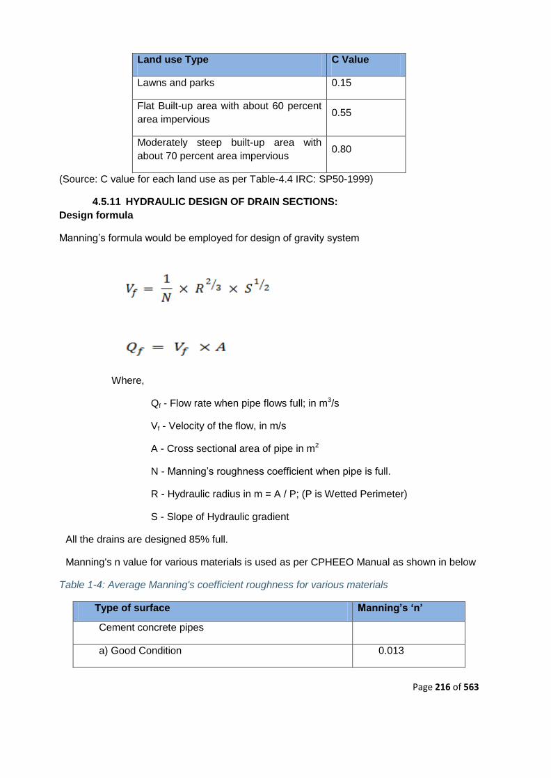
Page 216 of 563
Land use Type C Value
Lawns and parks 0.15
Flat Built-up area with about 60 percent
area impervious 0.55
Moderately steep built-up area with
about 70 percent area impervious 0.80
(Source: C value for each land use as per Table-4.4 IRC: SP50-1999)
4.5.11 HYDRAULIC DESIGN OF DRAIN SECTIONS:
Design formula
Manning‘s formula would be employed for design of gravity system
Where,
Qf - Flow rate when pipe flows full; in m3/s
Vf - Velocity of the flow, in m/s
A - Cross sectional area of pipe in m2
N - Manning‘s roughness coefficient when pipe is full.
R - Hydraulic radius in m = A / P; (P is Wetted Perimeter)
S - Slope of Hydraulic gradient
All the drains are designed 85% full.
Manning's n value for various materials is used as per CPHEEO Manual as shown in below
Table 1-4: Average Manning's coefficient roughness for various materials
Type of surface Manning‟s „n‟
Cement concrete pipes
a) Good Condition 0.013

Page 217 of 563
Type of surface Manning‟s „n‟
b) Fair Condition 0.015
Brick pitched drain 0.017
Plastered brick surface 0.015
Plastered brick surface with neat cement finish 0.013
Dry rubble masonry 0.033
Dressed ashler surface 0.015
Dry stone pitching 0.020
Kutcha drain 0.025
Earth
a) in ordinary condition 0.025
b) with stones and weeds 0.030
c) in poor condition 0.035
(Source: IRC: SP: 50 Table-4.3 and CPHEEO, 2013 Table 3.11)
The values highlighted in above table are used in the present study.
4.5.12 MINIMUM AND MAXIMUM VELOCITIES
While deciding the drain sections it is also required to keep in view the velocity in the drain.
Drains are designed to achieve a minimum self-cleaning velocity of 0.60 m/sec as per
CPHEEO at the design flow and a limiting maximum velocity up to 3.0 m/sec as per standard
engineering practice.
4.5.13 MINIMUM FREE BOARD
With reference to clause 4.9.3 of IRC -SP 50(b), free board adopted for drain varies from 100
mm to 300mm based on the bottom width of drain.
Table 1-5: Free Board Criteria for Storm water drainage
Sr.No. Drain Width (M) Free Board (M)
1 < 0.3 0.1
2 0.3 to 0.9 0.15
3 0.9 to 1.5 0.3
4 > 1.5 Depends on discharge
(Source: IRC : SP-50-1999)

Page 218 of 563
4.5.14 DESIGN SOFTWARE
Hydraulic design of storm water drain is modelled by using computer modelling software
Bentley Systems Storm CAD V8i. The storm water drains are provided on both the sides of
the road to collect the discharge from plots and road surface.
Steps for Developing Storm Water Network Model
The following steps will be followed to carry out the design storm water network,
The storm water network model for project area will be developed and
analysed using Bentley‘s Storm-CAD -V8i program.
The contour map for the above mentioned area will be brought into Storm-
CAD background and drainage network of minor and major catchments shall be
carried out.
Data inputs for catchment areas, runoff coefficients, time of concentration, IDF
curves, shape, size and material of drains, topographic model etc, will be provided.
Hydraulic design and analysis of entire storm water network done for 5 year
return period considering rainfall intensity more than 88 mm/hr
4.5.15 DESIGN CRITERIA FOR STORM WATER DRAIN
Surface drains are considered as far as possible. Open Drains with FRP covers/ Box
culverts will be considered at some locations like road crossing / adverse slope etc.
Surface drains will be covered with FRP. Boundary catchment drains may be
uncovered.
Rectangular section shall be provided for surface drains.
Minimum size of internal drains will be 300 mm X 300 mm.
4.5.16 DISPOSAL SCHEME
The HFL of the trunk drain in which proposed drainage system (drains along the internal
roads) is discharging should be lower than the IL of the incoming drain. The proposed layout
of the storm water drainage scheme is planned along the sides of the main arterial roads and
peripheral boundary. Individual plot developer is expected to connect their internal
drains to these main drains planned for the project area.
4.5.17 LOCATION OF OUTFALL
There are multiple possible out fall locations identified for the project area
1) Outfall-1: Discharge of storm water into Bada / Panchsheel nallah flowing
towards lower lake along the east site boundary.
Table 1-8: Outfall and flow from outfall
Sr. No. Free Outfall No. Flow
Cum/sec. % Flow
1 O4 5.27 33.6

Page 219 of 563
4.5.18 RAIN WATER HARVESTING SYSTEM
The development of 148.67 Ha of ABD area will turns into integrated urban place which
results in to an inevitable rise in site impermeability. Storm events will result in increased
overland runoff for the same catchment area and lag time to peak flooding will significantly
decrease. The natural annual recharge to existing aquifers on site will also reduce
substantially.
Rainwater harvesting is a technology used to collect, convey and store rain water for later
use from relatively clean surfaces such as a roof, land surface or rock catchment. The water
is generally stored in a rainwater tank or directed to recharge groundwater. Rainwater
infiltration is another aspect of rainwater harvesting playing an important role in storm water
management and in the replenishment of the groundwater.
The practice of collecting rainwater from rainfall events can be classified into two broad
categories: roof-based and land-based. Roof- based rainwater harvesting refers to collecting
rainwater runoff from roof surfaces which usually provides a much cleaner source of water
that can be also used as non-potable used after suitable treatment. Land-based rainwater
harvesting occurs when runoff from land surfaces and road surfaces is collected in furrow
dikes, ponds, tanks and reservoirs.
4.5.19 RAIN WTER HARVESTING DESIGN CONSIDERATIONS
Rainwater Harvesting, which implies conservation of rainwater is a tradition-renewed
scientific technology applied to augment the groundwater both quantitatively and qualitatively.
Three most important components, which need to be evaluated for designing the rainwater
harvesting structure, are:
Hydrogeology of the area including nature and extent of aquifer, soil
cover, topography, depth to water levels and chemical quality of ground water.
Area contributing for runoff i.e. how much area and land use pattern, whether
industrial, residential or green belts and general built up pattern of the area.
Hydro-meteorological characters like rainfall duration, general pattern and
intensity of rainfall.
4.6 HVAC
4.6.1 AMBIENT CONDITIONS:
Outside design conditions considered for Bhopal in summer are:
a) Dry Bulb 41.7 ºC
b) Wet Bulb 22.0 ºC
4.6.2 VENTILATED AREAS:
Basement - car park for Haat Bazaar shall be designed considering 6 air
changes per hour in normal mode operation and total of 12 air changes per hour
during fire mode. Energy saving strategies shall be applied to maintain the permitted
indoor temperature rise 5° C above ambient.

Page 220 of 563
Toilets ventilation fans shall be designed considering 12 air changes per hour
of continuous operations.
4.6.3 DESIGN PARAMETERS:
Design parameter for selection of Vane Axial Fans and its components shall be:
a) Maximum face velocity across filters : 100 M/Min.
b) Maximum fan outlet velocity : 600 M/Min
c) Maximum fan speeds - fans above 300 mm dia. 1000 RPM
-fans up to & including
300 mm dia. : 1400 RPM
d) Maximum fan motor speed : 1450 RPM
Design Parameter for Supply/ Fresh air ducting shall be:
a) Maximum flow velocity : 450 m/min
b) Maximum friction : 1 cm. WG/100 m run
c) Maximum velocity at supply air outlet : 210 m/min.
Design Parameter for Exhaust air ducting shall be:
a) Maximum flow velocity : 600 m/min
b) Maximum velocity at exhaust air outlet : 250 m/min.
4.6.4 SYSTEM DESCRIPTION
Mechanical ventilation system is proposed for basement car park area of Haat
Bazaar. The system comprises of smoke spill axial exhaust fans installed near
exhaust air cutout located in the basement. Sizing of these fans shall be based on 6
ACPH in normal mode and additional 6 ACPH in fire mode as per NBC. Fresh air
required shall be taken through ramp openings and also dedicated fresh air cut outs
of basement wall. There are 2 numbers cut-outs of basement slab for fan each with
11000 CFM x 2 Nos. Axial fans are planned to serve the purpose. Air from different
parts of the basement shall be collected through jet fans.
All lift wells shall be provided with Pressurization system, consisting of supply air fans
installed on roof top. These fans shall be connected to supply air ducts which are
connected to the lift well portion above terrace level. Fans shall be sized for lift well,
and/or to maintain minimum positive pressure of 50 Pa across the lift door. Supply air
fans serving lift well shall be provided with motorized damper at fan discharge to
prevent humid fresh air entering into the system. These dampers shall be interlocked
with fan motor and shall open upon getting signal from the smoke sensor upon
sensing of smoke in corridors/common passengers/ lift lobby.
All Pump room & Meter room are provided with wall mounted propeller fans. The
exhaust air is drawn at 20 ACPH by exhaust fan and the supply air will be supplied
through fresh air louvers.

Page 221 of 563
All vane axial and tube axial fans shall be fire rated for 250 Deg. C @ 2 hrs rating.
These fans shall be installed to provide easy access and maintenance clearance.
In normal mode, all supply openings shall collect fresh air from the atmosphere;
however all the exhaust axial fans with centrifugal jet fans with CO sensor shall
remove the hot and contaminated air from the basement and thus provide the
necessary ventilation effect. Ventilation of Basement - car park for Haat Bazaar can
be achieved by operating fans based on time based program or by receipt of signal
from CO sensor placed in basement.
Also fire rated tube axial fans shall be used for lift well pressurization, lift lobby
pressurization & Stairwell pressurization. These fans shall be installed on the terrace
and shall be connected to lift well,stairwell & lift lobby through GSS ductwork.
Whenever signal is received from fire panel these fans shall be started.
Heat sensors/ smoke detectors are proposed in the basement near lift to alert in case
of generation of heat & smoke in case of fire.
4.6.5 OPERATION PHILOSOPHY
Entire basement divided into single zone with two exhaust fan cutout in ceiling slab.
These cutout shall accommodate two (2) Numbers vane axial type smoke spill fans
and centrifugal type jet fans with CO sensors. Any one fan will be operated in normal
mode and both the fans will be operated in fire mode. In normal case these two fans
can be operated based of sequence to operation to achieve run time equalization of
these fans. In case of fire both fans shall run simultaneously for provide quick smoke
evacuation from the basement. Centrifugal jet fans shall be of dual speed type &
these can be operated on CO level.
Postulated failures
a) All centrifugal and tube axial fans are provided with redundant fans In case the
working fan fails to operate, the redundant fan is switched ON automatically.
b) The Basement ventilation system and lift well pressurization system is provided
with dedicated emergency power backup. In case of normal power failure or in case
of fire hazards, these systems operate on emergency power backed by DG Sets.
c) In the event of fire, the following strategy shall be used -.
The smoke detector located in every zone, shall sense the smoke and sends a signal
to the fire panel which in turn sends a signal to the vane axial fan with centrifugal jet
fan located in basement and tube axial fans located on terrace to operate in fire
mode.
We are not considering air-conditioning for any floor, it depends upon shop owners.
We shall be considered only electrical load for transformer capacity.
4.6.6 GENERAL REQUIREMENT
Ventilation System:

Page 222 of 563
The Ventilation fan Catalogue for fans shall be submitted by bidders along with the
bid. Final selection or rating charts/ performance curves for fans with duty point
marked, detailed working (fabrication/ construction) drawings for complete ventilation
equipment/ system including ducting, final G.A drawings for fans, detailed foundation /
mounting arrangement drawings for fans, static and dynamic
loads for fans, wall/ roof opening requirement details, operation and maintenance
manuals etc. shall be furnished by the Vendor for the Engineer‘s approval / reference,
after award of contract.
Drive motors for all ventilation fans shall be rated at least 15 % higher than the power
requirement at duty point or 10 % higher than the maximum power requirement at
selected speed, whichever is higher. Starting torque requirements of fans shall also
be considered to finalize the motor ratings.
The fans selected shall have steep curves to ensure nearly constant air flow even for
a significant variation in static pressure.
The static pressures, indicated in the fan data sheets and air flow diagrams submitted
by Bidder are for bid purpose only. The Vendor shall again submit the fan static
pressures on the basis of final approved drawings and the fans supplied shall deliver
the required static pressures at no extra price implications.
The Vendor shall ensure that the fans selected shall be conveniently installed in the
allocated fan rooms/ spaces without any installation and maintenance problems.
4.7 PLUMBING
4.7.1 SCOPE OF WORK
This specification covers the general requirements of providing and laying water
mains and water supply piping, providing and fixing sanitary fixtures and piping and
providing and laying drainage lines.
For specifications, mode of measurements and scope of work covered under the
respective items for the work included under this contract, following documents shall
be referred to in the order of precedence as given below:
a) Description of the items and notes if any given in the Schedule of
Quantities.
b) Drawings
c) Specifications.
d) Additional / Special Conditions of Contract.
e) General Conditions of Contract.
f) Applicable Codes and Standards as specified herein with
amendments/ revisions issued till date.

Page 223 of 563
In the event of any discrepancy among the documents referred above, the document
in the higher order of precedence shall prevail.
In the event of any element of specification not being available in any of the
documents mentioned above, the instructions of the Engineer-in-Charge in writing
shall be followed by the Contractor.
The Work shall be carried out in accordance with the drawings and designs as would
be issued to the Contractor by the Engineer-in-Charge duly signed and stamped by
him. The Contractor shall not take cognisance of any drawings, designs,
specifications, etc. not bearing Engineer-in-Charge's signature and stamp. Similarly
the Contractor shall not take cognisance of instructions given by any other Authority
except the instructions given by the Engineer-in-Charge in writing.
The Work shall be executed and measured as per metric dimensions given in the
Schedule of Quantities, drawings etc.
The Contractor shall acquaint himself fully with the partial provisions for supports that
may be available in the structure and utilise them to the extent possible. In any case
the Contractor shall provide all the supports regardless of provisions that have been
already made. Nothing extra shall be payable for situations where bed plates (for
supports) are not available or are not useful.
The Contractor shall incorporate seismic considerations of anchoring and isolation in
the design of the systems as called for the different equipment.
Shop coats of paint that may be damaged during shipment or erection shall be
cleaned off with mineral spirits, wire brushed and spot primed over the affected areas,
then coated with paint to match the finish over the adjoining shop painted surface.
In addition to the sectional testing carried out during the construction, the Contractor
shall test the entire installation after connections to the overhead tanks or pumping
system or mains. He shall rectify all leakage and shall replace all defective materials
in the system. Any consequential damage done, on account of Contractors
carelessness, open or burst pipes or failure of fittings, during testing and
commissioning to the building, furniture and fixtures shall be made good by the
Contractor.
4.7.2 GENERAL PROVISION
4.7.2.1 Scaffolding
Only steel tube scaffolding of approved design shall be used for all works. The
scaffold structure shall comply with the requirements of IS: 4014 and IS: 3696. An
independent tied scaffold (double scaffold), which has two lines of standards, shall be
provided with the inner line kept at least one board clear of the finished face with
extended transoms, or hop up baskets to carry an inside board. Diagonal braces shall
not prevent the material being moved along the scaffold run. The scaffolding shall be
suitably packed at the ends to prevent damage to the finished work.

Page 224 of 563
4.7.2.2 Protection
Protection against damage: Care shall be taken to avoid damage from any cause at
all stages. Packing pieces used for protection shall not disfigure or otherwise
permanently mark the Works.
Surface protection shall be afforded by careful handling and the avoidance of the use
of hooks, crowbars, or other implements that are likely to damage the works.
During installation of piping, open end of pipe shall be protected with temporary cover
to prevent dust or other materials entering in it.
Protection during construction: Decorative surfaces shall be carefully protected during
construction by a temporary cover.
Protection of finished work: At all stages of the Contract it is essential that all works
are properly protected.
Suitable packing shall be used to ensure that scaffolding does not damage erected
stone, marble, granite or other finished works.
Any disfigurement, discolouration or imperfection whatsoever due to any reason shall
not be accepted and the Contractor shall either remedy the same or redo the work at
no extra cost. The decision of the Engineer-in-Charge as to whether any work either
in whole or in part is acceptable or not shall be final and binding on the Contractor.
4.7.2.3 Guarantee
The Contractor shall guarantee and undertake to maintain and rectify the various
components of the Plumbing work installed by him for successful performance for a
period as indicated in the Datasheet-A. The Contractor shall indemnify the Engineer-
in-Charge for a similar period against any damage to property and injury to persons
on account of any defective work or maintenance carried out by the Contractor. The
format and text of the Guarantee and the Indemnity Bond shall be given by the
Engineer-in-Charge.
4.7.3 APPLICABLE CODES, STANDARDS AND PUBLICATIONS
All equipment, supply, erection, testing and commissioning shall comply with the
requirements of Indian Standards and code of practices given below as amended till
date. All equipment and material being supplied by the contractor shall meet the
requirements of IS, and other Codes/ Publications as given below.
SP:6(1) Structural steel sections
IS:325 Three phase induction motors
IS:554 Dimensions for pipe threads where pressure tight joints
are required on the threads
IS:694 PVC insulated cables for working voltages up to and
including 1100 V.
IS:779 Specification for water meters (domestic type)
IS:800 Code of Practice for general construction in steel
IS:1068 Electroplated coatings of nickel plus chromium and

Page 225 of 563
copper plus nickel plus chromium
IS:1172 Code of Basic requirements for water supply drainage
and sanitation
IS:1367 (Part 1) Technical supply conditions for threaded steel
fasteners: Part I Introduction and general information
IS:1367 (Part 2) Technical supply conditions for threaded steel
fasteners: Part 2 Product grade sand tolerances.
IS:1554 PVC insulated (heavy duty) electric(Part 1) cables: Part 1
For working voltages up to and including 1100 V.
IS:1554 (Part 2) PVC insulated (heavy duty) electric cables: Part 2 For
working voltages from3.3 kV up to and including 11 kV.
IS:1726 Specification for cast iron man hole covers and frames
IS:1742 Code of practice for building drainage
IS:2064 Selection, installation and maintenance of sanitary
appliances - Code of practice
IS:2065 Code of practice for water supply in buildings
IS:2104 Specification for water meter boxes(domestic type)
IS:2373 Specification for water meters (bulk type)
IS:2379 Colour code for identification of pipelines.
IS:2527 Code of practice for fixing rain water gutters and down
pipes for roof drainage
IS:2629 Recommended practice for hot dip galvanizing on iron
and steel
IS:3114 Code of practice for laying of cast iron pipes
IS:4111 (Part 1) Code of practice for ancillary structures in sewerage
system: Part 1Manholes
IS:4127 Code of practice for laying glazed stoneware pipes
IS:4853 Recommended practice for radiographic inspection of
fusion welded butt joints in steel pipes
IS:4985 Unplasticised PVC pipes for potable water supplies –
specification.

Page 226 of 563
IS:5329 Code of practice for sanitary pipe work above ground for
buildings
IS:5455 Cast iron steps for manholes
IS:6159 Recommended practice for design and fabrication of
material prior to galvanising
IS:7558 Code of practice for domestic hot water installations
IS:8321 Glossary of terms applicable to plumbing work
IS:9668 Maintenance of water supplies and fire fighting.
IS:9842 Preformed fibrous pipe insulation
IS:9912 Coal tar based coating materials and suitable primers for
protecting iron and steel pipe lines
IS:10221 Code of practice for coating and wrapping of underground
mild steel pipelines
IS:10234 Recommendations for general pipeline welding
IS:10446 Glossary of terms relating to water supply and sanitation
IS:11149 Rubber Gaskets
IS:11790 Code of practice for preparation of butt welding ends for
pipes, valves, flanges and fittings
IS:12183 (Part 1) Code of practice for plumbing in multi-storeyed buildings:
Part 1 Water Supply
IS:12251 Code of practice for drainage of building basements
BS:5572 Code of practice for sanitary pipe work
BS:6700 Specification for design, installation, testing and
maintenance of services supplying water for domestic
use within buildings and their cartilages
BS:8301 Code of practice for building drainage
BSEN274 Sanitary tap ware, waste fittings for basins, bidets and
baths. General technical specifications
IS:458 Specification for precast concrete pipes(with and without
reinforcement)

Page 227 of 563
IS:651 Salt glazed stoneware pipes and fittings
IS: 1239 (Part 1) Mild steel tubes, tubular and other wrought steel fittings:
Part 1 Mild steel tubes
IS:1239 Mild steel tubes, tubular and other wrought steel fittings:
IS:1536 Centrifugally cast (spun) iron pressure pipes for water,
gas and sewage
IS:1538 Cast iron fittings for pressure pipes for water, gas and
sewage
IS:1729 Sand cast iron spigot and socket soil, waste and
ventilating pipes, fitting sand accessories
IS:1879 Malleable cast iron pipe fittings
IS:1978 Line pipe
IS:1979 High test line pipe
IS:2501 Copper tubes for general engineering purposes
IS:2643 (Part 1) Dimensions for pipe threads for fastening purposes: Part
1 Basic profile and dimensions
IS: 2643 (Part 2) Dimensions for pipe threads for fastening purposes: Part
2 Tolerances
IS:2643 (Part 3) Dimensions for pipe threads for fastening purposes: Part
3 Limits of sizes
IS:3468 Pipe nuts
IS:3589 Seamless or electrically welded steel pipes for water, gas
and sewage(168.3mm to 2032mm outside diameter)
IS:3989 Centrifugally cast (spun) iron spigot and socket soil,
waste and ventilating pipes, fittings and accessories
IS:4346 Specifications for washers for use with fittings for water
services
IS:4711 Methods for sampling steel pipes, tube sand fittings
IS:6392 Steel pipe flanges
IS:6418 Cast iron and malleable cast iron flanges for general
engineering purposes.

Page 228 of 563
IS:7181 Specification for horizontally cast iron double flanged
pipes for water, gas and sewage.
IS:778 Specification for copper alloy gate, globe and check
valves for water works purposes
IS:780 Specification for sluice valves for water works purposes
(50mm to 300mmsize)
IS:1703 Specification copper alloy float valves (horizontal plunger
type) for water supply fittings.
IS:2906 Specification for sluice valves for water works purposes
(350mm to 1200 mm size)
IS:3950 Specification for surface boxes for sluice valves
IS:5312 (Part 1) Specification for swing check type reflux (non return)
valves: Part 1Single door pattern
IS:5312 Specification for swing check type reflux (non return)
valves: Part 2 Multi door pattern
IS:12992 Safety relief valves, spring loaded: (Part 1) Part1Design
IS:13095 Butterfly valves for general purposes
IS:771(Part 1 to 3) Specification for glazed fire clay sanitary appliances
IS:774 Specification for flushing cistern for water closets and
urinals (other than plastic cistern)
IS:775 Specification for cast iron brackets and supports for wash
basins and sinks
IS:781 Specification for cast copper alloy screw down bib taps
and stop valves for water services
IS:1700 Specification for drinking fountains
IS:2326 Specification for automatic flushing cisterns for
IS:2548 (Part 1) Specification for plastic seats and covers for water
closets: Part 1:Thermoset seats and covers
IS: 2548(Part 2) Specification for plastic seats and covers for water
closets: Part 2:Thermoplastic seats and covers
IS:2556(Part 1) Specification for vitreous sanitary appliances (vitreous
china): Part 1:General requirements

Page 229 of 563
IS:2556(Part 2) Specification for vitreous sanitary appliances (vitreous
china) Part 2:Specific requirements of wash down water
closets
IS:2556(Part 3) Specification for vitreous sanitary appliances (vitreous
china) Part 3 :Specific requirements of squatting pans
IS:2556(Part 4) Specification for vitreous sanitary appliances (vitreous
china) Part 4 :Specific requirements of wash basins
IS:2556
(Part 6 Sec 2)
Specification for vitreous sanitary appliances (vitreous
china) Part 6 :Specific requirements of urinals, Section 2
Half stall urinals
IS:2556
(Part 6 Sec 4)
Specification for vitreous sanitary appliances (vitreous
china) Part 6 :Specific requirements of urinals, Section 4
Partition slabs
IS:2556
(Part 6 Sec 5) Specification for vitreous sanitary appliances (vitreous
china) Part 6 :Specific requirements of urinals, Section 5
waste fittings
IS:2556
(Part 6 Sec 6) Specification for vitreous sanitary appliances (vitreous
china) Part 6 :Specific requirements of urinals, Section 6
Water spreaders for half stall urinals
IS:2556(Part 7) Specification for vitreous sanitary appliances (vitreous
china) Part 7 :Specific requirements of half round
channels
IS:2556(Part 8) Specification for vitreous sanitary appliances (vitreous
china) Part 8: Specific requirements of symphonic wash
down water closets.
IS:2556(Part 11) Specification for vitreous sanitary appliances (vitreous
china) Part 11:Specific requirements for shower rose
IS: 2556(Part 12) Specification for vitreous sanitary appliances (vitreous
china) Part 12:Specific requirements of floor traps
IS:2556 (Part 15) Specification for vitreous sanitary appliances (vitreous
china) Part 15:Specific requirements of universal water
closets
IS:2692 Specification for ferrule for water services
IS:2717 Glossary of terms relating to vitreous enamel ware and
ceramic metal systems

Page 230 of 563
IS:2963 Specifications for copper alloy waste fittings for wash
basins and sinks
IS:3311 Specification for waste plug and its accessories for sinks
and wash basins.
IS:5961 Specification for cast iron gratings for drainage purposes.
IS:6249 Specification for flush valves and fittings for marine use
IS:6411 Specification for gel coated glass fibre reinforced
polyester resin bath tubs
IS:8931 Specification for copper alloy fancy single taps,
combination tap assembly and stop valves for water
services
IS:9758 Specification for flush valves and fitting for water closets
and urinals
4.7.4 QUALITY ASSURANCE AND QUALITY CONTROL
The Work shall conform to high standards of design and workmanship, shall be
structurally sound and aesthetically pleasing. Quality standards prescribed shall form
the backbone for the quality assurance and quality control system.
At the site level the Contractor shall arrange the materials, their stacking/ storage in
appropriate manner to ensure the quality. Contractor shall provide equipment and
manpower to test continuously the quality of materials, assemblies etc. as directed by
the Engineer-in-Charge. The test shall be conducted continuously and the result of
tests maintained. In addition the Contractor shall keep appropriate tools and
equipment for checking alignments, levels, slopes and evenness of surface.
The Engineer-in-Charge shall be free to carry out tests as may be considered
necessary by him at his sole discretion, from time to time, in addition to those
specified in this document. The Contractor shall provide the samples and labour for
collecting the samples. Nothing extra shall be payable to the Contractor for samples
or for the collection of the samples.
The test shall be conducted at the site laboratory that may be established by
Engineer-in-Charge or at any other Standard Laboratory selected by Engineer-in-
Charge.
The Contractor shall transport the samples to the laboratory for which nothing extra
shall be payable. In the event of Contractor failing to arrange transportation of the
samples in proper time Engineer-in-Charge shall have them transported and recover
two times the actual cost from the Contractor's bills.
Testing charges shall be borne by the Contractor.
Testing may be witnessed by the Contractor or his authorised representative.
Whether witnessed by the Contractor or not, the test results shall be binding on the
Contractor.

Page 231 of 563
4.7.5 SANITARY WARE AND OTHER APPLIANCES
4.7.5.1 Scope of Work
Without restricting to the generality of the foregoing, sanitary and other appliances
shall inter-alia include the following:-
Sanitary appliances and fixtures for toilets
Chromium plated brass fittings
Stainless steel sinks
Accessories e.g. towel rods, toilet paper holders, soap dish, liquid soap dispensers,
towel rails, coat hooks etc.
Mirrors, hand driers, drinking water fountains, etc.
Whether specifically mentioned or not the Contractor shall provide for all appliances
and fixtures all fixing devices, nuts, washers, Teflon tape, sealant, cement, brackets,
supports, paints, connectors, cp riser pipes, adopters, bolts, screws, hangers etc as
required.
All exposed pipes within toilets and near appliances/ fixtures shall be of chromium
plated brass or copper unless otherwise specified.
4.7.5.2 General Requirements
All materials shall be new and of quality conforming to specifications and subject to
the approval of the Engineer-in-Charge. Wherever particular makes are mentioned,
the choice of selection shall remain with the Engineer-in-Charge.
All appliances, fixtures and fittings shall be provided with all such accessories as are
required to complete the item in working condition whether specifically mentioned or
not in the Schedule of Quantities, specifications, and drawings. Accessories shall
include proper fixing arrangement, brackets, nuts, bolts, washers, screws and
required connection pieces.
Fixing screws shall be half round head chromium plated (CP) brass screws, with CP
brass washers unless otherwise specified.
Porcelain sanitary ware shall be glazed vitreous china of first quality free from warps,
cracks and glazing defects conforming to IS: 2556. The choice of the colour of the
Sanitary ware shall be that of the Engineer-in-Charge and nothing extra shall be
payable to the Contractor for fixing of Sanitary ware of any colour.
Sinks for kitchen shall be of stainless steel or as specified in the Schedule of
Quantities.
Chromium plated fittings shall be cast brass chromium plated of the best quality
approved by the Engineer-in-Charge.
If supply of sanitary appliances, fixtures & fittings are in client‘s scope, no damages
shall occur to the same during shifting, transportation, installation till successful
handing over. If any damage occurs, the same shall be replaced by the contractor at
his own cost.
All appliances, fittings and fixtures shall be fixed in a neat workmanlike manner true to
level and to heights shown on the drawings and in accordance with the manufacturer
recommendations. Care shall be taken to fix all inlet and outlet pipes at correct
positions. Faulty locations shall be made good and any damage to the finished floor,
tiling, plaster, paint, insulation or terrace shall be made good by the Contractor at his
own cost.

Page 232 of 563
All materials shall be rust proofed; materials in direct or indirect contact shall be
compatible to prevent electrolytic or chemical (bimetallic) corrosion.
Sanitary appliances, subject to the type of appliance and specific requirements, shall
be fixed in accordance with the relevant standards and the following:
a) Contractor shall, during the entire period of installation and afterwards
protect the appliances by providing suitable cover or any other protection in
order to absolutely prevent any damage to the appliances until satisfactory
handing over. (The original protective wrapping shall be left in position for as
long as possible).
b) The appliance shall be placed in correct position or marked out in
order that pipe work can be fixed or partially fixed first.
c) The appliance shall be fixed in a manner such that it will facilitate
subsequent removal if necessary.
d) All appliances shall be securely fixed. Manufacturers' brackets and
fixing methods shall be used wherever possible. Compatible rust proofed
fixings shall be used. Fixing shall be done in a manner that minimises noise
transmission.
e) Appliances shall not be bedded (e.g. WC pans, pedestal units) in thick
strong mortar that could crack the unit (e.g. a ceramic unit).
f) Pipe connections shall be made with de-mountable unions. Pipe work
shall not be fixed in a manner that it supports or partially supports an
appliance.
g) Appliances shall be fixed so that water falls to the outlet (e.g. baths).
h) All appliances shall be secured as per the recommendations of
manufacturer.
i) Appliances shall be fixed true to level firmly fixed to anchor or supports
provided by the manufacturer and additional anchors or supports where
necessary.
Sizes of Sanitary fixtures given in the Specifications or in the Schedule of Quantities
are for identification with reference to the catalogues of makes considered.
Dimensions of similar models of other makes may vary within +/-10% and the same
shall be provided and no claim for extra payment shall be entertained nor shall any
payment be deducted on this account.
4.7.5.3 Water Closet
WC shall be wash down or symphonic wash down type floor or wall mounted set, as
shown in the drawings, designed for low volume flushing from 3-6 litres of water,
flushed by means of a flushing cistern or an exposed or concealed type (as detailed
in the drawings or as directed by the Engineer-in-Charge) 32mm size CP brass flush
valve with regulator valve. Flush pipe/ bend shall be connected to the WC by means

Page 233 of 563
of a suitable rubber adaptor. Wall hung WC shall be supported by CI floor mounted
chair which shall be fixed in a manner as approved by the Engineer-in-Charge.
Each WC set shall be provided with a solid plastic seat, rubber buffers and chromium
plated brass hinges. Plastic seat shall be so fixed that it remains absolutely stationary
in vertical position without falling down on the WC.
Each WC set shall be provided with a fixed type CP brass ablution jet, if called for in
schedule of quantities, complete with CP/ plastic piping, concealed type CP brass
angle cock etc. all of approved make and brand. The nozzle of the ablution jet and its
holding down plate shall have smooth and rounded edges and shall not be capable of
causing any injury to a user or cleaner.
4.7.5.4 Pan Connector
The WC pan connector shall be Flexible, soft and shall be made of single body
construction with integral fins, made from EVA (Ethyl Vinyl Acetate). The pan
connector must confirm to the BS: 5627: 1984. The pan connector must be supplied
with factory fitted spring loaded seal guard.
The connector shall not be allowed to come in contact with mineral oil, grease, putty
or any compound containing mineral oil or grease.
The pan connectors must be stored away from the direct sunlight and flames.
While fixing of the pan connector with the Soil pipe, the pipe must be reasonably
clean and smooth on the inner surface; in case the soil piping is in C.I. then supplier
supplied bush / adaptor shall be used. The connector socket is pushed fully home
onto the pan spigot; thereafter the WC is placed in position gently pushing the fitment
to ensure that the connector end fits into the Spigot of the pipe. The pan connector
must be pushed in such an easy as to ensure that the seals and fins turn inward to
ensure proper sealing.
4.7.5.5 Urinals
Urinals shall be lipped type half stall white glazed vitreous china of size as called for
in the Schedule of Quantities.
Half stall urinals shall be provided with 15mm diameter CP spreader, 32mm diameter
CP domical waste and CP cast brass bottle/‖P‖ trap with pipe and wall flange and
shall be fixed to wall by CI brackets, CI wall clips and CP brass screws as
recommended by manufacturer complete as directed by the Engineer-in-Charge.
Flushing for urinals shall be by means of no hand operation, PVC or ceramic flushing
cistern / electronic auto flush valve with all internal fittings, mounted on a C.I.
brackets, and painted with two coats of approved paint of approved shade and
confirming to IS: 2326.
Flush pipes shall be PVC pipes concealed in wall chase but with chromium plated
bends at inlet and outlet or as given in Schedule of Quantities. These shall be
measured and paid for separately.

Page 234 of 563
PVC waste pipes shall be provided for urinals. Waste pipes may be exposed on wall
or concealed in chase as directed by the Engineer-in-Charge. These shall be
measured and paid for separately.
4.7.5.6 Urinal Partitions
Urinal partitions shall be white glazed vitreous china of size specified in the Schedule
of Quantities.
Porcelain partitions shall be fixed at proper heights with CP brass bolts, anchor
fasteners and MS clips as recommended by the manufacturer and directed by the
Engineer-in-Charge.
4.7.5.7 Wash Basin
Wash basins shall be white glazed vitreous china of size, shape and type specified in
the Schedule of Quantities.
Each basin shall be provided with painted MS angle or C.I. brackets and clips and the
basin securely fixed to wall. Placing of basins over the brackets without secure fixing
shall not be accepted. The MS angle shall be provided with two coats of red oxide
primer and two coats of synthetic enamel paint of make, brand and colour as
approved by the Engineer-in-Charge.
Each basin shall be provided with 32mm diameter CP waste with overflow, pop-up
waste or rubber plug, CP angle valve, CP riser pipe with connectors / adaptors and
CP brass chain as specified in the Schedule of Quantities, 32mm diameter CP brass
bottle trap with CP pipe to wall flange.
Wash basin shall be provided with hot and cold water mixing fitting or as specified in
the Schedule of Quantities.
Basins shall be fixed at proper heights as shown on drawings. If height is not
specified, the rim level shall be 790mm from finished floor level or as directed by the
Engineer-in-Charge.
4.7.5.8 Sinks
Sinks shall be stainless steel or any other material as specified in the Schedule of
Quantities.
Each sink shall be provided with painted MS or CI brackets and clips and securely
fixed. Counter top sinks shall be fixed with suitable painted angle iron brackets or
clips as recommended by the manufacturer. Each sink shall be provided with 40mm
diameter CP waste, CP angle valve, CP riser pipe with connectors / adaptors and
rubber plug with CP brass chain as given in the Schedule of Quantities. The MS
angle shall be provided with two coats of red oxide primer and two coats of synthetic
enamel paint of make, brand and colour as approved by the Engineer-in-Charge.
Flow Rate = 4.5 to 6 Litres per minute @ 80 PSI
Supply fittings for sinks shall be deck mounted CP swivel faucets with or without hot
and cold water mixing fittings as specified in the Schedule of Quantities. These shall
be measured and paid for separately.
4.7.5.9 Toilet Paper Holder
Toilet paper holder shall as specified in the Schedule of Quantities or of stainless
steel/powder coated brass.
Porcelain toilet paper holder shall be fixed in walls and set in cement mortar 1:2 (1
cement: 2coarse sand) and fixed in relation to the tiling work.

Page 235 of 563
The latter shall be fixed by means of crews/capping having finish similar to the toilet
paper holder in wall/ timber partitions with rawl plugs or nylon sleeves. When fixed on
timber partition, it shall be fixed on a solid wooden base ember provided by the
Engineer-in-Charge through another agency.
4.7.5.10 Liquid Soap Dispenser
Liquid Soap dispenser shall be wall/ counter mounted suitable for dispensing liquid
soaps, lotions, detergents as specified in schedule of quantities.
Liquid soap dispenser shall be with C.P. brass bracket, caps etc. fixed to wall with
C.P. brass screws, and screwed onto wooden rawl plug. The container shall be of
C.P. brass.
4.7.5.11 Hand Drier
The hand drier shall be no touch operating type with solid state time delay to allow
user to keep hand in any position.
The hand drier shall be fully hygienic, rated for continuous repeat use (CRU).
The rating of hand drier shall be such that time required to dry a pair of hands up to
wrists is approximately 30 seconds.
The hand drier shall be of wall mounting type suitable for 230 V, single phase, 50 Hz,
ac power supply.
The material of construction, size and finishing shall be as specified in schedule of
quantities.
4.7.5.12 Robe Hook
Robe hook shall be chromium plated brass or of stainless steel or powder coated
brass of size, shape and type specified in the Schedule of Quantities.
Robe hook shall be fixed with screws/capping having golden finish in wall/doors with
rawl plugs or nylon sleeves and shall include screwing and making good as required
or directed by the Engineer-in-Charge.
4.7.5.13 Paper Towel Dispenser
Paper towel dispenser shall be wall/ counter mounted suitable for dispensing paper
towels.
Paper towel dispenser shall be with C.P. brass bracket, caps etc. fixed to wall with
C.P. brass screws, and screwed onto wooden rawl plug. The container shall be of
C.P. brass.
4.7.5.14 Health Faucet
These shall be of CP / sanitary ware. The make and model shall be as specified in
Schedule of Quantities. These shall be fixed by means of stainless steel counter sunk
screws to wooden/ plastic cleats firmly embedded in the wall.
15 mm CP health faucet with 1.2m long flexible tube with end nuts & Hook.
1 No 15mm CP brass angular stop cock with wall flange
Hook with CP brass counter sunk screws.
4.7.5.15 Toilets For Disabled
Where specified, in washroom facilities designed to accommodate physically
disabled, accessories shall be provided as directed by the Owner‘s Site
Representative.
Stainless steel garb brass of required size suitable for concealed or exposed
mounting and opened non-slip gripping surface shall be provided in all washroom.
The flushing cistern/valve shall be provided with chromium plated long handles.

Page 236 of 563
4.7.5.16 Pillar Cock
Pillar cock shall of CP brass material table mounted type for cold water inlet of
approved quality as specified in the Schedule of Quantities. Make & model shall be as
per client section. Pillar Cock shall be provided with Suitable Approved type of Angle
Cock.
4.7.5.17 Measurement And Rates
Not used
4.7.5.18 Mockup And Trial Assembly
The installation of the sanitary fixtures and fittings shall be as per the shop drawings
approved by the Architect/Consultant.
The contractor shall have to assemble at least one set of each type of sanitary
fixtures and fittings in order to determine precisely the required supply and disposal
connections. Relevant instructions from manufacturers shall be followed as
applicable. This trial assembly shall be developed to determine the location of
puncture holes, holding devices etc. which will be required for final installation of all
sanitary fixtures and fittings. The above assembly shall be subject to final approval by
the Architect / Interior Designer.
The fixtures in the trial assembly can be re-used for final installation without any
additional payments for fixing or dismantling of the fixtures.
4.7.5.19 Supporting And Fixing Devices
The contractor shall provide all the necessary supporting and fixing devices to install
the sanitary fixtures and fittings securely in position. The fixing devices shall be rigidly
anchored into the building structure. The devices shall be rust resistant and shall be
so fixed that they do not present an unsightly appearance in the final assembly.
Where the location demands, the Architect may instruct the contractor to provide
chromium plated or other similarly finished fixing devices. In such circumstances the
contractor shall arrange to supply the fixing devices and shall be installed complete
with appropriate vibration isolating pads, washers and gaskets.
4.7.5.20 Final Installation
The contractor shall install all sanitary fixtures and fittings in their final position in
accordance with approved trial assemblies and as shown on drawings. The
installation shall be complete with all supply and waste connections. The connection
between building and piping system and the sanitary fixtures shall be through proper
unions and flanges to facilitate removal/replacement of sanitary fixtures without
disturbing the built in piping system. All unions and flanges shall match in appearance
with other exposed fittings.

Page 237 of 563
4.7.6 SOIL, WASTE, VENT AND RAINWATER PIPES
4.7.6.1 Scope Of Work
Soil, waste, vent and rain water disposal scope shall includes Supply, Installation,
testing, commissioning and successful handing over to client as per the drawings,
specifications and schedule of quantities.
All soil, waste and storm water disposal for the portion above ground level to the
public sewers shall be by gravity, whereas from the basements it shall be by
pumping. Without restricting to the generality of the foregoing, the soil, waste, vent
and rain water pipes system shall inter-alia include the following:
Vertical and horizontal soil, waste, vent and rainwater pipes and fittings, joints,
supports, paints and connections to fixtures.
Connection of all pipes to sewer lines as shown on the drawings at ground level.
Floor and urinal traps, clean out plugs, inlet fittings and rainwater (roof) outlets.
Testing of all pipes and fittings in the workshop.
Testing, commissioning and handing over of all pipes lines after installation.
4.7.6.2 General Requirements
Pipes and fittings shall be fixed truly vertical, horizontal or in slopes as required in a
neat workmanlike manner.
Pipes shall be fixed in a manner so as to provide easy accessibility for repair and
maintenance and shall not cause obstruction in shafts, passages etc.
Pipes shall be securely fixed to walls, and ceilings by suitable clamps at intervals
specified. Only approved type of anchor fasteners shall be used for fixing pipes on
RCC ceilings and RCC/ masonry walls.
Access doors for fittings and clean outs shall be so located that they are easily
accessible for repair and maintenance.
Long bends shall be used on all main pipelines as far as possible. Use of elbows shall
be restricted for short connections.
Wherever piping is going across the separation/expansion joints of buildings, piping
shall be provided with flexible connectors on both sides of such joints or on single
side depending on whether any wall is to be crossed or not.
4.7.6.3 UPVC & PVC Pipework
UPVC SWR pipe work shall be provided for above ground soil, waste, vent & rain
water pipe work as shown in drawings. UPVC SWR pipes & fittings shall confirm to
IS: 13592 & IS: 14735 respectively. Pipes shall be of Type - B, pressure rating
6kgs/cm2. The pipes shall be supplied in nominal lengths of 2, 3, and 4 or 6 meters,
tolerance on specified lengths shall be +10mm and – 0mm. Any physical test
requirements shall be as per IS13592-1992.
Soil, waste & vent pipes shall be uPVC pipes & fittings.
PVC (SWR) class pipes of diameter 75 mm, 110 mm, 160 mm, 200 mm and 300 mm,
of Type/Grade A (conforming to IS:4985 and 6 kg / cm2) for use in rain water (unless
otherwise specified) and of Type B for soil, waste and ventilation system and
conforming to IS 13592: 1992, shall be used. The pipes shall be supplied in nominal
lengths of 2, 3, and 4 or 6 meters, tolerance on specified lengths shall be +10mm and
– 0mm. Any physical test requirements shall be as per IS 13592-1992.

Page 238 of 563
4.7.6.4 Handling
Because of their lightweight, there may be a tendency for the UPVC pipes to be
thrown often during installation. Reasonable care should be taken in handling and
storage to prevent damage to the pipes. The pipes shall be stored as per
manufacturer‘s recommendation. The contractor shall be fully responsible in this
case. In no case, pipes should be dragged on the ground. Pipes should be
given adequate supports at all times.
4.7.6.5 Pipe Work Installation
UPVC pipes shall be laid under the flooring or hanging below slab or fixed on walls
either buried or exposed as the case may be, as shown in the drawings. The
minimum thickness of fittings shall be of 3.2 mm. the fittings shall be of injection
mould type with solvent cement joint (for exposed piping) or rubber ring joint (for
concealed piping). The pipes and fittings shall be capable of withstanding sun‘s
rays. UPVC/PVC pipes laid below slab or suspended from ceiling shall be supported
by GI angle brackets / supports as detailed in the drawings.
All vertical pipes shall be fixed by GI or MS clamps truly horizontal. Branch pipes shall
be connected to the stack at the same angle as that of the fittings. No collars shall be
used on vertical stacks. Each stack shall be terminated at top with a vent cowl
(terminal guard).
Horizontal pipes running along ceiling shall be fixed on structural adjustable clamps of
special design shown on the drawings or as directed. Horizontal pipes shall be laid to
uniform slope and the clamps adjusted to the proper levels so that the pipes fully rest
on them.
Contractor shall provide all sleeves, openings, hangers and anchor fasteners during
the construction. Sleeves shall be one size higher then pipe or there should be at
least 12 mm gap all around between pipes & sleeves. Wherever pipe passes through
fire rated wall, the gap shall be filled with fire rated sealant as directed by engineer.
For non-fire rated wall, gap shall be filled with wool & silicon sealant (20 mm depth).
Contractor shall provide all necessary information to the building work contractor for
making such provisions in the structure as necessary. All damages shall be made
good by the Contractor at his own cost to restore the surface.
Door type fittings shall be used in vertical piping installations. Door position of fittings
shall be on top of fitting. Access door shall be made easily removal. The access door
shall be air and water tight. Single - yee shall be used for horizontal branch
connection. Double - yee fittings shall be used in vertical piping branch connection
only.
4.7.6.6 Jointing
UPVC/PVC pipes & fittings shall be joined as per the manufacturer‘s instructions /
recommendations. UPVC/PVC pipes and fittings shall be joined with Solvent Cement
and jointing shall be carried out as follows
Cut the spigot end of the pipe square.
All burrs from the internal and external surfaces should be removed.
The spigot should be marked with a pencil line at a distance equivalent to the socket
depth. Clean the surface within the marked area.
Apply uniform coat of approved solvent cement on the external surface to the pipe
and a lighter coat on the internal surface of the fitting.

Page 239 of 563
Insert the pipe end into the socket of the fitting and push it in upto the mark.
The pipe work should be assembled in a manner such that it does not entail making
of joints in restricted area.
4.7.6.7 UPVC/PVC Pipe Work Testing
UPVC/PVC pipes and fittings assembled shall be tested in accordance with IS 13592
- 1992. The openings of the pipes shall be sealed for the section to be tested. The
water column of 2m and shall be maintained for a maximum of 15 minutes. Contractor
with their team shall examine carefully all the joints for leakage.
The Contractor shall test all vent pipes by a smoke testing machine. Smoke shall be
pumped into the stack after plugging all inlets and connections and filling water in all
trap seals. The test shall be conducted under a pressure of 25 mm of water and shall
be maintained for 15 minutes. The stack shall then be observed for leakages and all
defective pipes and fittings removed or repaired as directed by the Engineer-in-
Charge.
A test register shall be maintained and all entries signed and dated by Contractor and
Engineer-in-Charge. A pro-forma of the proposed test register shall be submitted to
the Engineer-in-Charge for approval.
All pipes in wall chase or meant to be encased or buried shall be hydro tested before
the chase is plastered or the pipe encased or buried.
All systems shall be tested in sections as required to expedite the work for other
trades and meet construction schedules and final test on completion.
4.7.6.8 Waste Pipe From Appliances
Waste pipe from appliances e.g. washbasins, baths, sinks and urinals etc. shall be of
UPVC confirming IS 4985 as given in the Schedule of Quantities.
The internal diameter sizes of outlet branch waste pipes for different fittings shall be
as follows :
Wash basin - 32 dia
Urinals - 50 dia
Sink - 50 dia
Nahani Trap - 75 diameter, 50 mm seal
Multi Floor Trap - 75 or 100 dia. as required, with 50 mm or
75 mm seal / bolted aluminium grating in 2525 MS angle
P Trap - 75 mm water seal as required with
bolted aluminium grating in 2525 MS angle
All pipes shall be fixed in gradient towards the outfalls of drains. Pipes inside a toilet
room shall be in chase unless otherwise shown on drawings. Where required pipes
may be run at ceiling level in suitable gradient and supported on structural clamps as
directed by the Engineer-in-Charge. Spacing for the clamps shall be 3000mm for
vertical runs and 2400mm for horizontal runs.

Page 240 of 563
Pipes shall be UPVC tubes conforming to IS: 4985 and quality certificates shall be
furnished. Pipes shall be provided with all required fittings conforming to IS: 4985 e.g.
tees couplings, bends, elbows, unions, reducers, nipples, plugs etc. All UPVC waste
pipes shall be terminated at the point of connection with the appliance with an outlet
of suitable diameter. Pipes shall be painted as specified under Clause Error!
eference source not found..
The pipes shall be of class III, 6 Kg/cm2. The pipes shall conform to IS 4985 - 2000.
Fittings shall be of injection moulded PVC conforming to IS 7834 (Part1) - 1975.
Pipe sleeves and inserts, etc. through RCC wall of buildings either external or internal
or for water tanks shall be of PVC provided with water bar flanged.
W.C. pan connectors shall suit the requirements as per drawing, with 40 dia. vent
horn for connection to the anti-siphonage pipe. Pan connector shall be of C.I. or lead.
Connection to the sewer or storm water collection sumps to be perfectly water tight
and as specified in the drawing.
Rainwater flashing shall be of 150 100 or 230 150 fitted on to the bell mouth of
rainwater pipes inlet and then covered with cast iron grating and extension piece.
All rainwater pipes and fittings shall be soil type variety conforming to I.S. 1729-1964
or equivalent. This shall apply to pipe outside buildings within the building or in
separate shafts.
Bathroom C.P. grating shall be having bolted down design out of heavy cast brass
with chromium plating of the best approved standards.
Cast iron grating shall be flat with perfect edge and of the best quality procurable of
the specified width and thickness and in the available length.
4.7.6.9 Pipe Laying And Fixing
The pipe laying and jointing shall be done in accordance with IS 7634 (Part 3) – 1975.
Pipes shall be cut to size and chamfered well. Burr‘s if any shall be removed. Pipes
and fittings shall be jointed using solvent cement or rubber ring joints. The pipes and
fittings shall be jointed accurately without any stress to achieve leak proof joints.
4.7.6.10 Testing
The method which is commonly in use is filling the pipe with water, taking care to
evacuate any entrapped air and slowly raising the system to the test pressure at
3Kg/cm2. The pressure testing may be followed as follows. The field test pressure to
be imposed should be not less than the greatest of the following:
One and half times of maximum sustained operating pressure.
One and half times the maximum pipe line static pressure.
Sum of the maximum sustained operating pressure and the maximum surge
pressure.
Sum of the maximum pipe line static pressure and the maximum surge pressure,
subject to a maximum equal to the works test pressure for any pipe fittings
incorporated.
The field test pressure should wherever possible be not less than 2/3rd working
pressure and should be applied and maintained for at least four hours. If the visual
inspection satisfies that there is no leakage the test can be passed.

Page 241 of 563
A test register shall be maintained and all entries signed and dated by Contractor and
Engineer-in-Charge. A Performa of the proposed test register shall be submitted to
the Engineer-in-Charge for approval.
All pipes in wall chase or meant to be encased or buried shall be hydro tested before
the chase is plastered or the pipe encased or buried.
4.7.6.11 Cuting And Making Good Holes / Chases
Pipes shall be fixed and tested as the building work proceeds. Contractor shall
provide all necessary holes, cut outs and chases in structural members as the
building work proceeds. Wherever holes are cut or left originally, they shall be made
good with cement concrete 1:1:2 (1 cement: 1coarse sand :2 stone aggregate 20mm
nominal size) or cement mortar 1:2 (1 cement :2 coarse sand) as directed by the
Engineer-in-Charge and the surface restored as in original condition to the entire
satisfaction of the Engineer-in-Charge at no extra cost.
4.7.6.12 Drainage Accessories
Floor Trap / Urinal Trap Grating
Floor/ urinal traps grating shall be of stainless steel square / round of size 125 x 125
mm square/round as approved by client & shown in the drawing. Floor trap assembly
shall be provided with round stainless steel strainer basket as a cockroach trap.
Entire assembly shall be complete with ring, frame, outer cup, inner cup, grating,
screws etc. of an approved make.
Floor Cleanout
Floor cleanout cover shall be of stainless steel square / round of size 125 x 125 mm
square/round as approved by client & shown in the drawing. Floor cleanout assembly
shall be complete with ring, outer frame, cover, screws etc. of an approved make.
Ceiling Cleanout
Ceiling cleanout cover shall be in nickel bronze / PVC plug type / GI flanged type of
round shape matching pipe size as approved by client & shown in the drawing.
Ceiling cleanout assembly shall be threaded with key hole for opening / flanged type
suitable for pipe. Threaded cover shall be used up to 100 mm size & above shall be
GI flanged type with GI nuts & bolts. PVC cover shall be used for PVC drainage
piping only, whereas nickel bronze & GI flanged type cover shall be used for HDPE /
CI / CI LA pipe work.
Cockroach Traps
Floor/ urinal traps shall sealed cover provided with 100-150mm square or round
stainless steel cockroach trap assembly complete with ring, outer cup, inner cup, jali
etc. of an approved make.
Wire Balloons / Grating For Rain Water Pipes
The wire balloons and the domical gratings shall conform to IS: 1729. The wire
balloons shall be of galvanised steel. The CI domical gratings for the roof outlet shall
be minimum 13mm thick.
Leaf and Gravel grates along with a perforated ring shall be made out of M.S.
flat/bars of a design and dimension as shown in the drawing or as directed by the
Engineer-in-Charge. These shall be painted with epoxy paint with a DFT of 200
microns.
Wire balloons/gratings for rainwater pipes shall be measured by numbers for different
sizes. Leaf and gravel grates along with the perforated ring shall be measured in kgs.
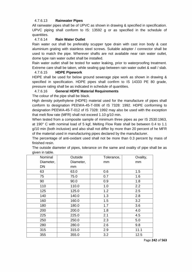
Page 242 of 563
4.7.6.13 Rainwater Pipes
All rainwater pipes shall be of UPVC as shown in drawing & specified in specification.
UPVC piping shall conform to IS: 13592 g or as specified in the schedule of
quantities.
4.7.6.14 Rain Water Outlet
Rain water out shall be preferably scupper type drain with cast iron body & cast
aluminium grating with stainless steel screws. Suitable adopter / connector shall be
used to match the pipe. Wherever shafts are not available near rain water outlet,
dome type rain water outlet shall be installed.
Rain water outlet shall be tested for water leaking, prior to waterproofing treatment.
Extreme care shall be taken, while sealing gap between rain water outlet & wall / slab.
4.7.6.15 HDPE Pipework
HDPE shall be used for below ground sewerage pipe work as shown in drawing &
specified in specification. HDPE pipes shall confirm to IS 14333 PE 80 grade,
pressure rating shall be as indicated in schedule of quantities.
4.7.6.16 General HDPE Material Requirements
The colour of the pipe shall be black.
High density polyethylene (HDPE) material used for the manufacture of pipes shall
conform to designation PEEWA-45-T-006 of IS 7328: 1992. HDPE conforming to
designation PEEWA-45-T-012 of IS 7328: 1992 may also be used with the exception
that melt flow rate (MFR) shall not exceed 1.10 g/10 min.
When tested from a composite sample of minimum three pipes as per IS 2530:1963,
at 190° C with nominal load of 5 kgf, Melting Flow Rate shall be between 0.4 to 1.1
g/10 min (both inclusive) and also shall not differ by more than 20 percent of he MFR
of the material used in manufacturing pipes declared by the manufacturer.
The percentage of anti-oxidant used shall not be more than 0.3 percent by mass of
finished resin.
The outside diameter of pipes, tolerance on the same and ovality of pipe shall be as
given in table.
Nominal
Diameter,
DN
Outside
Diameter,
mm
Tolerance,
mm
Ovality,
mm
63 63.0 0.6 1.5
75 75.0 0.7 1.6
90 90.0 0.9 1.8
110 110.0 1.0 2.2
125 125.0 1.2 2.5
140 140.0 1.3 2.8
160 160.0 1.5 3.2
180 180.0 1.7 3.6
200 200.0 1.8 4.0
225 225.0 2.1 4.5
250 250.0 2.3 5.0
280 280.0 2.6 9.8
315 315.0 2.9 11.1
355 355.0 3.2 12.5

Page 243 of 563
Nominal
Diameter,
DN
Outside
Diameter,
mm
Tolerance,
mm
Ovality,
mm
400 400.0 3.6 14.0
450 450.0 4.1 15.6
500 500.0 4.5 17.5
560 560.0 5.0 19.6
630 630.0 5.7 22.1
Three pipes, in accordance with IS 2530:1963, the carbon black content shall be
within 2.5 (+-) 0.5 percent and the dispersion of carbon black shall be satisfactory.
Tolerance on outside diameter and maximum ovality:
The values specified for tolerance on outside diameter have been calculated as 0.009
DN, rounded off to the next higher 0.1 mm, subject to minimum of 0.3 mm. No
negative tolerances are allowed.
The pressure rating of HDPE pipes specials shall be confirming to IS: 14333 or
equivalent international standard with temperature & maximum allowable operating
pressure criteria as per IS: 14333.
Each straight length of the pipe shall clearly be marked in inedible ink/paint (inkjet
printing) at every one meter with the following information:
The manufacturer‘s name and /trademark
Designation of the pipe as per the standard specified.
Lot number/Batch number/year of mfg.
The words ―PROJECT NAME‖.
All HDPE fabricated fittings shall be manufactured from the pipe itself made out of
same raw material & dimensions as specified above. Fitting shall be strictly fabricated
in factory at pipe manufacturing facility. Necessary certificate to be provided by the
manufacturer. No fabrication or moulding will be allowed at site, unless specifically
permitted by the Engineer.
Manufacturer to provide drawings for HDPE fittings and non HDPE specials.
4.7.6.17 HDPE Pipe Work Jointing
Pipes shall be joined using butt fusion joint. Manufacturer's recommendation /
instructions shall be strictly followed during pipe jointing procedure.
4.7.6.18 Measurement and Rates
Not Used
4.7.6.19 Clamps
Wherever MS/GI clamps are required to be anchored directly to brick walls, concrete
slabs, beams or columns, nothing extra shall be payable for clamping arrangement,
RCC block and making good with cement concrete 1:2:4 mix (1 cement:2
sand:4stone aggregate 20mm nominal size) as directed by the Engineer-in-Charge.
4.7.6.20 Angels / Channels
Slotted angles/ channels shall be measured per linear metre of finished length and
shall include support bolts and nuts, length embedded in the cement concrete blocks
of 1:2:4 (1cement: 2 coarse sand: 4 stone aggregate 20mm nominal size) formed in
the masonry walls; nothing extra shall be paid for the cement concrete block and
making good the masonry wall, anchor fasteners etc. complete.
Page 244 of 563
4.7.6.21 Manhole Covers
The Cast Iron Manhole Cover and Frame shall conform to IS: 1726 and the grade and
types have been specified in the Bill of Quantities. The cover and frames shall be
cleanly cast and they shall be free from air and sand holes and from cold shuts. They
shall be neatly dressed and carefully trimmed. All castings shall be free from voids
whether due to shrinkage, gas inclusion or other causes. Covers shall have a raised
checkered design on the top surface to provide an adequate non-slip grip.
The sizes of covers specified shall be taken as the clear internal dimensions of the
frame. The internal diameter of the manhole is 600mm.
The covers and frames shall be coated with a black bituminous composition. The
coating shall be smooth and tenacious. It shall not flow when exposed to a
temperature of 63° C and shall not brittle as to chip off at a temperature of 0° C.
4.7.6.22 Steps/Foot Rest/Rungs
Steps shall be provided wherever the depth of the manhole / chamber is more than
1.2 m. Foot rest shall be C.I. rungs weighing 5.3 kg and conforming to IS 5455-1969
or made up of 20 mm diameter polypropylene foot rest with M.S. reinforcement
square or round bars as specified. These shall be embedded 20 cm deep in 20 20 10 cm blocks of P.C.C. 1:3:6. The blocks with M.S. or C.I. foot rest placed in its
centre shall be cast in site along with masonry.
Footrest shall be placed 300 mm apart vertically and 375 mm horizontally in
staggered fashion. First footrest shall be 450 mm below top. Footrest shall be painted
with bituminous paint and the portion embedded shall be painted with thick cement
slurry before fixing.
4.7.6.23 Installation Of Soil, Waste & Vent Pipes
All Horizontal pipes running below the slab and along the ceiling shall be fixed on
structural adjustable clamps, sturdy hangers of the design as called for in the
drawings. The pipes shall be laid in uniform slope and proper levels. All vertical
pipes shall be truly vertical fixed by means of stout clamps in two sections, bolted
together, built into the walls, wedged and neatly jointed. The branch pipes shall be
connected to the stack at the same angle as that of fittings. All connections between
soil, waste and ventilating pipes and branch pipes shall be made by using pipe
fittings with inspection doors for cleaning. Pipes shall be fixed in a manner as to
provide easy accessibility for repair and maintenance and shall not cause
obstruction in shafts. Where the horizontal run off the pipe is long or where the pipes
cross over building expansion joints etc. suitable allowance shall be provided for any
movements in the pipes by means of expansion joint etc. such that any such
movement does not damage the installation in any way.

Page 245 of 563
Before joining, the interior of the socket and exterior of the spigots shall be
thoroughly cleaned and dried. The spigot end shall be inserted into the socket right
up to the back of the socket and carefully centered by two or three laps of threaded
spun yarn, twisted into ropes of uniform thickness, well caulked into the back of the
socket. No piece of yarn shall be shorter than the circumference of the pipe. The
jointed pipe line shall be at required levels and alignment. The reminder of the
socket is left for the lead caulking. Where the gasket has been tightly held, a jointing
ring shall be placed round the barrel against the face of the socket. Molten Lead
shall be poured to the remainder of the socket.
The joint shall not be covered till the pipe line has been tested under pressure. Rest
of pipe line shall be covered so as to prevent the expansion and contraction due to
variation in temperature.
Rainwater Pipes
All open terraces shall be drained by rain water down takes.
Rainwater down takes are separate and independent of the soil and waste system
and will discharge to rain water harvesting tank and excess rain water will be diverted
to the external storm water drain.
WATER SUPPLY SYSTEM
Scope of Work
The scope shall include supply, installation, testing, commissioning and satisfactory
handing over of the complete water supply system to client as per drawings,
specifications and schedule of quantities. The water supply system shall inter-alia
include the following:
Distribution system from main supply or overhead tank to all fixtures and appliances
for cold water.
Pipe protection and painting.
Control valves, masonry chambers and other appurtenances.
Connections to all plumbing fixtures, tanks, appliances and municipal mains
Inserts, nozzles for R.C.C. tanks
The term water supply is used as indicative of all water supply work required and
necessary for the building including such external work as may be necessary to make
the system functional.

Page 246 of 563
The scope of this section comprises the supply, installation, testing and
commissioning of piping network for water supply for internal & external services as
follows:
a. Tapping from available main sourcel /Tanker water supply/
b. Domestic water supply.
c. Flushing water supply
The contractor shall make all necessary application and arrangements for his work to
be inspected by the Local Authorities.
The contractor shall be solely responsible for obtaining the Authorities approval of his
works prior to the handing over of the complete water supply / distribution installation
to the owner.
General Requirements
Clause 0 shall apply.
Clause 0 shall apply.
Clause 0 shall apply.
If necessary and if approved by the Engineer-in-Charge, where unavoidable, bends
may be formed by means of a hydraulic pipe bending machine for pipes up to 20mm
dia. No bending shall be done for pipes of 25mm diameter and above. After bending
zinc rich paint shall be applied wherever the zinc coating is damaged.
Valves and other appurtenances shall be so located as to provide easy accessibility
for operations, maintenance and repairs. Valves shall be located at a height not
exceeding 1.6m above their operating floor/ platform level. Where such a provision is
not possible and the valve is to be frequently operated a MS chain shall be provided
for its operation.
Clause 0 shall apply.
Gi Pipes, Fittings And Valves
All pipes inside the buildings and where specified, outside the building shall be M.S.
galvanized steel tubes conforming to IS: 1239 of Class specified. When Class is not
specified they shall be Heavy Class. All embedded / concealed pipes shall be of
heavy duty.

Page 247 of 563
Fittings shall be of malleable cast iron galvanized, of approved make. Each fitting
shall have manufacturer's trade mark stamped on it. Fittings for GI pipes shall include
couplings, bends, tees, reducers, nipples, unions, bushes etc. Fittings etc. shall
conform to IS: 1879.
Pipes and fittings shall be jointed with screwed joints using Teflon tape suitable for
water pipes. Care shall be taken to remove burr from the end of the pipe after cutting
by a round file. All pipes shall be fixed in accordance with layout and alignment shown
on the drawings. Care shall be taken to avoid air pockets. Necessary vents and
drains shall be provided at all high and low points respectively. GI pipes inside toilets
shall be fixed in wall chases well above the floor. No pipes shall be run inside a
sunken floor as far as possible. Pipes may be run under the ceiling or floors and other
areas as shown on drawings. All pipe joints after testing of the line shall be seal
welded and the weld plus the adjoining portion shall be given two coats of zinc rich
primer.
Bib Cocks And Stop Cocks
All bib cocks and stop cocks shall be of C.P. brass conforming to IS: 781 of tested
quality and approved make and design, of diameter as specified in schedule of
quantities.
Clamps
GI pipes in shafts and other locations shall be supported by GI clamps of design
approved by the Engineer-in-Charge. Pipes in wall chases shall be anchored by iron
hooks. Pipes at ceiling level shall be supported on structural clamps fabricated from
MS structural‘s as described in Clause Error! Reference source not found.. Pipes
n shafts shall be supported on slotted angles/ channels as specified/ as directed.
Unions
Contractor shall provide adequate number of unions on all pipes to enable easy
dismantling later when required. Unions shall be provided near each gunmetal valve,
stop cock or check valve and on straight runs as necessary at appropriate locations
as required for easy dismantling and/ or as directed by the Engineer-in-Charge.
Flanges
Flanged connections shall be provided on pipes as required for maintenance/ ease in
dismantling or where shown on the drawings, all equipment connections as
necessary and required or as directed by the Engineer-in-Charge. Connections shall
be made by the correct number and size of the GI nuts/ bolts as per relevant IS
Standards and made with 3mm thick insertion rubber washer/gasket. Where hot
water or steam connections are made insertion gasket shall be of suitable high

Page 248 of 563
temperature grade and quality approved by the Engineer-in-Charge. Bolt hole dia for
flanges shall conform to match the specification for CI sluice valve as per IS: 780.
Gaskets shall conform to IS: 11149.
Trenches
All GI/PVC/HDPE pipes running below ground shall have minimum cover of 600mm.
Excavation To Be Taken To Proper Depth
Excavation shall be done in all conditions of soil and to such a depth that the sewers /
or other pipes shall rest as described in the several clauses relating thereto and so
that the inverts may be at the levels given on the section. Should the contractor
excavate the trench to a greater depth than is required the extra depth shall have to
be filled up with concrete at the contractor‘s own cost to the requirements and
satisfaction of the client / consultants.
Back Filling (IS: 12288 – 19S87)
After the sewer or other piping work has been laid and proved to be water-tight, the trench or other excavation shall be refilled. Utmost care shall be taken in doing this so that no damage is caused to the sewer and other permanent works.
For the purpose of back filling, the depth of the trench or other excavation shall be considered as divided into the following three zones from the bottom of the trench of its top, for the purpose of refill materials to be used.
Zone A
From bottom level of trench or other excavation, to the level of the centre line of the pipe
Zone B
From the level of the centre line of the pipe to a level 30 cm above the top of the pipe, and
Zone C
From a level 30 cm above the top of the pipe to the top of the trench. or other
excavation
Backfill Materials
All backfill materials shall be free from cinders, ashes, slag, refuse, rubbish, vegetable
or organic materials, lumpy or frozen materials boulder, rocks or stone or other
materials which in the opinion of the client / consultants, is unsuitable for deleterious.

Page 249 of 563
Fine excavated earth which shall pass through a sieve of aperture size 20 mm can be
used for filling in zones A & B. However, material containing stones up to 20mm as
their greatest dimension may be used in zone C only unless otherwise specified by
the clients / consultants. Where excavated material in considered by the clients /
consultants not suitable for back filling, clean river sand shall be used for the same.
Backfill Sand
River sand used for back fill shall be natural sand complying with para 3.6 graded
from fine to coarse. The total weight of clay in it shall not exceed 10 percent. All
material shall pass through a sieve of aperture size 20mm (IS-2405-1980) and not
more than 5 percent shall remain on IS sieve of aperture size 6.30mm.
Backfill Gravel
Gravel used for back fill shall be natural gravel and having durable particles graded
from fine to coarse in a reasonably uniform combination with no boulders or stone
larger than 50mm in size. It shall not contain excessive amount of loam and clay and
not more than 15 percent shall remain on a sieve of aperture size 75 micron.
Back Filling In Zone A
It shall be done by hand with fine excavated material or river sand, fine gravel or other
approved materials placed in layers of 8cm and compacted by tapping. The back
filling material shall be deposited in the trench for its full width of each side of the
pipe, fittings and appurtenances simultaneously.
Back-Filling In Zone B
Back filling in zone B using fine excavated material shall be done by hand or
approved mechanical methods. Special care has to be taken during tamping to avoid
injuring or moving the pipe. If excavated material is not suitable, the type of back-fill
material shall be prescribed by the client / consultants to suite individual locations.
Back Filling In Zone C
It shall be done by hand or approved mechanical methods and well compacted.
Excavated earth having stones of size not exceeding 20 mm can be used for zone C.
If the excavated earth is unsuitable for back fill, the filling material shall be specified
by the client / consultants.
Painting
All pipes above ground shall be painted with one coat of red lead and two coats of
synthetic enamel paint of approved shade and quality to give an even shade, or as
specified by the Engineer-in-Charge.

Page 250 of 563
Hot water pipes in chase:
All hot water pipes fixed in wall chase shall be properly insulated by elastomeric tape
as per manufacturer‘s recommendation.
Pipe Protection
Where specified, pipes below floor or below ground shall be protected against
corrosion by the application of two or more coats of solvent based rubberised
asphaltic primer to give a uniform coat covered with 'Pipe coat Hiper', a puncture
resistant non woven polyester mat. The application of pipe coat primer and "Hiper"
membrane shall be as specified by the manufacturer.
Cpvc (Chlorinated Poly Vinyl Chloride) Pipes & Fittings
CPVC pipes & fittings solvent welded type shall be used for internal cold & hot water
supply piping work. CPVC pipes from 15mm to 50 mm shall be Class - 1, SDR-11
confirm to the requirements of IS 15778. CPVC pipes from 65mm to 300 mm shall be
schedule 40 / schedule 80 class confirm to the requirements of ASTM-F441 & as
described in the BOQ/SOQ.
Coefficient of thermal expansion- ASTM D - 696-6.3x10⁻⁵ m/m0K
Thermal conductivity – ASTM C 177 – 0.14 Wm/0K/m2
CPVC fittings i.e. sockets, tees, bends, reducers, brass threaded male/female
connectors, brass threaded male/female adopters unions, bushings etc shall comply
to the requirements of ASTM F438 & ASTM F439 for schedule 40 & schedule 80
class respectively. Solvent cement for CPVC pipe shall comply as per ASTM F493.
CPVC pipe work shall be installed strictly as per the recommendation of
manufacturer. CPVC pipe work shall be adequately supported by GI split clamps with
GI structural supports & GI threaded rods. CPVC pipe work shall be securely tight
with GI nuts, bolts & washers. Pipe work spacing shall be as per guidance of
manufacturers.
After completion of piping work, piping shall be hydraulically tested in parts with test
pumps at 10bar for 24 Hrs or 1.5 times working pressure, whichever is higher. CPVC
test plugs shall be used to seal the dead end of piping. Upon completion of entire
installations, the complete system shall be tested as described above.
Upon successful testing of entire piping system, it shall be painted with one coat of
approved primer & two coats of approved synthetic enamel paint, as per direction of
engineer-in-charge / client.

Page 251 of 563
Cpvc Piping Installation Procedure
Pipe shall be cut truly straight to the required length
Remove burr (shaving) & clean the cut portion with dry cloth. Ensure that jointing
portion is free from any dirt, grease or any other foreign material.
Install dry fit out, by inserting pipe inside the sockets up to 1/3rd to 2/3rd penetration
depths. Ensure that pipe inserts to the bottom of the sockets, without any resistance.
If pipe inserts is not to the sockets, then check with another fittings.
Apply a thin coat of solvent cement to the inner side of socket up to its bottom & full
coat to the outer side of pipe.
Insert pipe in to the socket, till the solvent is in fluid state. Twist the pipe turn to cover
any dry spots.
Hold the pipe for at least 30 seconds, to ensure proper jointing. Wipe out excess
solvent cement with clean dry cloth.
Allow joint to cure for at least 24 Hours.
For pipe greater than 50 mm diameter, pipe work shall be jointed with primer & heavy
duty solvent cement.
Teflon tape shall be used for threaded portion of fittings.
Manufacturer's recommendation shall be followed during pipe work installations.
Rating & Dimensional Details of CPVC Pipes SDR 11
Diameter & Wall thickness of CPVC pipes SDR – 11 are as per Table given below:
S.N. Nominal
pipe size
(mm)
Mean Outside diameter Wall Thickness
Min Max Mean Min Max Avg
Max
1 15 15.8 16.0 15.9 1.7 2.2 2.2

Page 252 of 563
2 20 22.1 22.3 22.2 2.0 2.5 2.5
3 25 28.5 28.7 28.60 2.6 3.1 3.1
4 32 34.8 35 34.9 3.2 3.7 3.7
5 40 41.2 41.4 41.3 3.8 4.3 4.3
6 50 53.9 54.1 54.0 4.9 5.5 5.5
Note: For CPVC Pipes SDR is calculated by dividing the average outer diameter of
the pipe in mm by the minimum wall thickness in mm. If the wall thickness calculated
by this formula is less than 1.52 m. The SDR values shall be rounded to the nearest
0.5
Pressure rating @230C – 27.6 Kg/cm2
Pressure rating @820C – 7.03 Kg/cm2
(FOR PIPE DIAMETER ABOVE 50MM Sch.40)
Nominal Pipe Size Outer Dia. Inner Dia. Wall Thickness Pressure Rating
(Inch) (mm) (mm) (mm) (mm) (Kg/cm2)
2½‖ 65 73.30 62.10 5.16 21.10
3‖ 80 88.90 77.27 5.49 18.28

Page 253 of 563
4‖ 100 114.30 101.50 6.02 15.47
6‖ 150 168.28 153.19 7.11 12.66
Pipes shall be painted with bituminous paint and covered with polythene tape and a
final coat of bitumen paint. Exposed pipes shall be painted with two or more coats of
Synthetic enamel paint. The portion embedded shall be painted with thick cement
slurry before fixing. Color to be verified as per IS standards for all the pipes.
Supports Spacing
CPVC pipe work supports shall be provided as per below table.
Nominal
Size
Pipe Size Support Spacing (Meter) Respectively with
Pipe Size
230C 380C 600C 800C
15 mm SDR 11 / SDR
13.5
1.22 /
1.22
1.22 / 1.22 1.07 / 1.07 0.92 / 0.92
20 mm SDR 11 / SDR
13.5
1.53 /
1.53
1.37 / 1.37 1.22 / 1.22 0.92 / 0.92
25 mm SDR 11 / SDR
13.5
1.68 /
1.68
1.53 / 1.53 1.37 / 1.37 0.92 / 0.92
32 mm SDR 11 / SDR
13.5
1.83 /
1.83
1.68 / 1.68 1.53 / 1.53 1.22 / 1.22
40 mm SDR 11 / SDR
13.5
1.98 /
1.98
1.83 / 1.83 1.68 / 1.68 1.22 / 1.22

Page 254 of 563
50 mm SDR 11 / SDR
13.5
2.29 /
2.29
2.14 / 2.14 1.98 / 1.98 1.22 / 1.22
65 mm SCH 40 / SCH
80
2.13 /
2.86
2.13 / 2.86 1.82 / 1.98 1.06 / 1.22
80 mm SCH 40 / SCH
80
2.13 /
2.59
2.13 / 2.59 1.82 / 2.13 1.06 / 1.22
100 mm SCH 40 / SCH
80
2.86 /
2.74
2.86 / 2.74 1.98 / 2.86 1.22 / 1.37
150 mm SCH 40 / SCH
80
2.59 /
3.04
2.59 / 2.89 2.13 / 2.59 1.37 / 1.52
Valves & Fittings:
Sluice Valves
Unless otherwise specified all valves 200 mm dia. and above shall be CI double
flanged sluice valves with non rising spindle. Sluice valves shall be provided with
wheel when they are in exposed positions and with a cap top when they are located
underground. Contractor shall provide suitable operating keys for sluice valves with
cap tops.
Sluice valves shall be of approved makes conforming to IS: 780 of Class as specified.
Butterfly Valves
Where specified, Valves 80 mm dia. and above shall be Cast steel or cast iron
butterfly valve to be used for isolation and/ or flow regulation as directed by the
Engineer. The valves shall be tight shutoff/ regulatory type with resilient seat suitable
for flow in either direction and seal in both directions.
Butterfly valve shall conform to IS: 13095.
Non Return Valve
Where specified non return valve (swing check type) shall be provided through which
flow can occur in one direction only. It shall be single door swing check type of best
quality conforming to IS: 5312.

Page 255 of 563
Forged Brass Ball Valve
Valves of size 50 mm dia. and below shall be full bore quarter turn lever operated
female threaded forged brass hard chrome plated ball valves conforming to IS: 554.
Valve shall have PTFE body seat rings and gland packing, forged brass ball, stem
and bonnet, carbon steel nut washer and lever and finished in chrome. Valves shall
have minimum working pressure of 16 bar. Valves shall be tested at manufacturer's
works and the same stamped on it.
Air Release Valve (Arv)
Pressurised water supply lines shall be provided with air release valve at highest
point to release accumulated air for piping system. Air release valve shall be
automatic float operated; the diameter shall be as specified in the Schedule of
Quantities. Air release valve shall be provided with ball valve for ease in Operation
and Maintenance. Valve body shall be in cast iron stainless steel, brass and EPDM
internal components. Valves shall have minimum working pressure of 10 Kegs.
Pressure Gauge:
Sr.
No
Description
1 Type : Glycerine filled & Direct
Reading
2 Casing : SS 304
3 Glass : Toughened borosilicate
shatterproof
4 Dial size : 150 mm
5 Wetted
Parts
(including
accessories)
: SS 316

Page 256 of 563
6 2-valve
manifold
: SS 316
7 Diaphragm
seal
: SS 316 (with suitable coating of
material if required)
8 Pointer : Aluminium
9 Movement &
socket
: SS 316
10 Accuracy : + 1.0 % of full scale
11 Process
Connection
: Bidder to State
12 Over range
protection
: 25% above maximum pressure
13 Accessories : Syphon for services above
75oC
Snubber for pump discharge
applications
Chemical diaphragm for
corrosive fluid lines (acid, alkali
etc.), in discharge of sludge
transfer pumps & in oil.
2-valve manifold (2-valve
manifold & snubber is not be
required for diaphragm seal
application.)

Page 257 of 563
SS name plate.
Expansion Bellow.
Heavy duty double flanged flexion rubber expansion joint (suitable for system test pressure)
of standard length as per manufacturers specs including rubber gaskets, flanges, nuts, bolts
and washers complete as required.
Ball Float Valve
Ball valves with Heavy duty floats to be fixed in storage tanks as shown in the
drawing, and shall consist of cast brass lever arm having copper balls (26 SWG)
screwed to the arm integrally. The copper ball shall have bronze welded seams. The
closing/opening mechanism incorporating the piston and cylinder shall be non-
corrosive metal and include washers. The size and construction of ball valves and
float shall be suitable for desired working pressure operating the supply system.
Testing
All pipes, fittings and valves shall be tested in accordance with IS: 2065 except as
may be modified herein under. All pipes, fittings and valves, after fixing at site, shall
be tested to a hydrostatic pressure of 10 kg/cm2 or 1.5 times the shut off head of the
pump whichever is greater.
The test pressure shall be maintained for a period of at least thirty minutes without
any drop in pressure.
A test register shall be maintained and all entries shall be signed and dated by
Contractor(s) and the Engineer.
After commissioning of the Water Supply System, the Contractor shall test each valve
by closing and opening it a number of times to observe if it is working efficiently and
effectively. Valves which do not operate efficiently and effectively shall be replaced by
new ones at no extra cost and the same shall be tested as above.
All pipes in wall chase or meant to be encased or buried shall be hydro tested before
the chase is plastered or the pipe encased or buried.
Pressure Reducing Valve Set
Each pressure reducing valve set shall be complete with pressure reducing or
pressure regulating valve, isolating valves, pressure gauges on inlet and outlet,
pressure relief valve on outlet and filter on inlet.

Page 258 of 563
Each pressure reducing valve shall contain loading neoprene diaphragm and a full
floating, self aligning, ignition resistant seat and shall be of the single stage, pressure
reduction type with provision for manually adjusting the delivery pressure. The valve
shall fail safe to the low pressure.
Valves shall be capable of operating at the maintaining automatically the respective
delivery pressure and flow rates as indicated and shall not be liable to creep. Valves
shall also be capable of maintaining the pre-set downstream pressure under static
condition.
The filter on each inlet to a pressure reducing valve shall be of replaceable porous
sintered metal type.
Pressure reducing valves are used to lower pipeline pressure to a predetermined set
point. Pressure reducing valves protect installations against excessive pressure from
the supply.
Pressure reducing valves automatically controls downstream pressure, from no flow
to full open flow, without regard to changes in inlet pressure. Outlet pressure control
is smooth and precise since the friction and hysteresis of the valve and pilot is
negligible.
Because the valve will not chatter or slam under low flow conditions, it is not
necessary to parallel pressure reducing valves with a second smaller size control
valve to obtain accurate pressure control at low flow rates. In any size, pressure
reducing valves will control pressure right down to shutoff.
Spring loaded pressure reducing valves operate by means of a force equalizing
system. The force of a diaphragm operates against the force of an adjustment spring.
If the outlet pressure and therefore diaphragm force fall because water is drawn, the
then greater force of the spring causes the valve to open. The outlet pressure then
increases until the forces between the diaphragm and the spring are equal again. The
inlet pressure has no influence in either opening or closing of the valve. Because of
this, inlet pressure fluctuation does not influence the outlet pressure, thus providing
inlet pressure balancing.
Pressure Relief Valves
Each pressure relief valve shall be of the fully enclosed type and fitted with hand
easing gear.
Each pressure relief valve in a pressure reducing station shall have a flow capacity
equal to that of the pressure reducing valve. PRV shall be of Brass.

Page 259 of 563
Pressure relief valves in locations other than reducing stations shall have flow
capacities equal to that of the associated equipment.
Level Controlled Solenoid Valves
A solenoid valve is an electromechanically operated valve. The valve is controlled by
an electric current through a solenoid: in the case of a two-port valve the flow is
switched on or off; in the case of a three-port valve, the outflow is switched between
the two outlet ports.
Level sensor based solenoid valve will be installed at terrace level for automatic
operation of the water transfer pump set.
Underground / Overhead Storage Tanks
Storage tanks for water supply shall be in RCC.
Each tank shall be provided with lockable type manhole cover fabricated from MS
sheet or standard cast iron tank covers. Manhole covers shall be of appropriate size
as directed by the Engineer-in-Charge.
Each storage tank shall be provided with high and low level annunciation by means of
magnetic level switches.
One solid state electronic annunciation panel fully wired with visual display and
audible alarm unit shall be provided to indicate the following:
High and low level alarms for each water storage tank.
On/ off status of all Pump sets namely domestic
All the necessary arrangements for fixing the panel shall be provided by the
Contractor.
All the cabling from the respective level switches to the Annunciation Panel, MCC
Switch gear to Annunciation Panel, including power supply from MCC shall be
provided by the Contractor.
The number of outgoing terminals shall be equal to the number of incoming terminals
from field/ MCC with 20% margin, so that necessary interconnection to BMS could be
done at a later date.
Testing

Page 260 of 563
All pipes, fittings and valves shall be tested in accordance with IS: 2065 except as
may be modified herein under. All pipes, fittings and valves, after fixing at site, shall
be tested to a hydrostatic pressure of 10 kg/cm2 or 1.5 times the shut off head of the
pump whichever is greater.
The test pressure shall be maintained for a period of at least thirty minutes without
any drop in pressure.
A test register shall be maintained and all entries shall be signed and dated by
Contractor(s) and the Engineer-in-Charge.
After commissioning of the water supply system, the Contractor shall test each valve
by closing and opening it a number of times to observe if it is working efficiently and
effectively. Valves which do not operate efficiently and effectively shall be replaced by
new ones at no extra cost and the same shall be tested as above.
All pipes in wall chase or meant to be encased or buried shall be hydro tested before
the chase is plastered or the pipe encased or buried.
Insulation
All open hot water flow and return pipes shall be insulated with preformed fibrous pipe
sections conforming to IS: 9842.
Insulation to pipes shall be with pre-moulded pipe sections, thickness for sections
shall be:
Pipe 50mm diameter and below - 25mm thick
Pipe 65mm diameter and above - 40mm thick
Application:
All surfaces shall be thoroughly cleaned with a wire brush.
One layer of approved primer shall be applied and pre-moulded pipe insulation
sections shall be fixed.
One layer of aluminium foil of thickness 0.711mm (20 SWG), shall be applied as a
finish layer.
Insulation for hot water pipes in chase:
All hot water pipes in chase shall be insulated with 3 mm elastomeric tape as per
manufacturer‘s recommendations.
Page 261 of 563
Disinfection Of Installation
The water supply installation shall be disinfected as per standards and as follows:
Tanks and pipes shall be filled and flushed out.
All bib cocks (taps) shall be closed.
Tanks and pipes shall be re-filled while adding sterilizing admixture containing 50
parts chlorine to one million parts water.
When the installation is filled all bib cocks (taps) shall be opened progressively and
each allowed running until the water smells of chlorine.
The installation shall be topped up and more sterilizer added.
The installation shall then be left for three hours and shall then be tested for residual
chlorine; if none is found, the installation shall be drained and the process repeated.
The installation shall be finally drained and flushed with potable water before use.
Connection To Rcc Water Tanks. (Puddle Flange)
The contractor shall provide all inlets, outlets, washouts, vents, ball cocks, overflows
control valves and all such other piping connections including level indicator to water
storage tanks as called for. All pipes crossing through RCC work shall have puddle
flanges fabricated from GI pipes of required size and length and welded to 6/8 mm
thick MS plate. All puddle flanges must be fixed in true alignment and level to ensure
further connection in proper order.
Full way gate valves of an approved make shall be provided as near the tank as
practicable on every outlet pipe from the storage tank except the overflow pipe.
Overflow and vent pipes shall terminate with mosquito proof grating with bronze
screen on vent.
The overflow pipe shall be so placed to allow the discharge of water being readily
seen. The overflow pipe shall be of size as indicated. A stop valve shall also be
provided in the inlet water connection to the tank. The outlet pipes shall be fixed
approximately 75mm above the bottom of the tank towards which the floor of the tank
is sloping to enable the tank to be emptied for cleaning.
The floor and the walls of the tank shall be tiled with glazed tiles up to the overflow
level. Alternatively food grade epoxy to be applied.
Water Meters

Page 262 of 563
Water meters of approved make and design shall be supplied for installation at
locations as shown. The water meters shall meet with the approval of local supply
authorities. Suitable valves and chambers or wall meter box to house the meters shall
also be provided along with the meters.
The meters shall conform to Indian Standard IS: 779 and IS: 2373. Calibration
certificate shall be obtained and submitted for each water meter.
Provision shall also be made to lock the water meter. The provision shall be such that
the lock is conveniently operated from the top. Where the provision is designed for
use in conjunction with padlocks, the hole provided for padlocks shall be a diameter
not less than 4mm.
(Note: The water meters to be installed and at every use of water such as Landscape
irrigation, Domestic, Flushing, Fire fighting etc.)
Installation Of Water Meters And Stop Cock
The G.I. lines shall be cut to the required lengths at the position where the meter and
stop cock are required to be fixed. Suitable fittings shall be attached to the pipes. The
meter and stop cock shall be fixed in a position by means of connecting pipes, jam
nut and socket etc. The stop cock shall be fixed near the inlet of the water meter. The
paper disc inserted in the ripples of the meter shall be removed. And the meter
installed exactly horizontal or vertical in the flow line in the direction shown by the
arrow cast on the body of the meter. Care shall be taken that the factory seal of the
meter is not disturbed. Wherever the meter shall be fixed to a newly fitted pipe line,
the pipe line shall have to be completely washed before fitting the meter.
Disinfection Of Piping System And Storage Tanks
Before commissioning the water supply system, the contractor shall arrange to
disinfect the entire system as described in the succeeding paragraph.
The water storage tanks and pipes shall first be filled with water and thoroughly
flushed out. The storage tanks shall then be filled with water again and disinfecting
chemical containing chlorine added gradually while tanks are being filled to ensure
thorough mixing. Sufficient chemical shall be used to give water a dose of 50 parts of
chlorine to one million parts of water.
If ordinary bleaching powder is used, the proportions will be 150 gm of power to 1000
litres of water. The power shall be mixed with water in the storage tank. If a

Page 263 of 563
proprietary brand of chemical is used, the proportions shall be specified by the
manufacturer. When the storage tanks are full, the supply shall be stopped and all the
taps on the distributing pipes are opened successively working progressively away
from the storage tank. Each tap shall be closed when the water discharged begins to
smell of chlorine. The storage tank shall then be filled up with water from supply pipe
and added with more disinfecting chemical in the recommended proportions. The
storage tank and pipe shall then remain charged at least for three hours. Finally the
tank and pipes shall be thoroughly flushed out before any water is used for domestic
purpose.
The pipe work shall be thoroughly flushed before supply is restored.
Sterilization Of Main
After the pipe work has been tested and approved, but before it is coupled, it shall be
sterilized with a solution of chloride of lime. The water supply installation shall be
sterilized as per standards and as follows:
a) Tanks and pipes shall be filled and flushed out.
b) All bibcock (taps) shall be closed.
c) Tanks and pipes shall be re-filled while adding sterilizing admixture containing
50 parts chlorine to one million parts water.
d) When the installation is filled all bibcock (taps) shall be opened progressively
and each allowed running until the water smells of chlorine.
e) The installation shall be topped up and more sterilizer added.
The installation shall then be left for three hours and shall then be tested for residual
chlorine; if none is found, the installation shall be drained and the process repeated.
Level Sensors
Level sensor shall consist of control unit, preamplifier and one full insulated probe-
mounted vertically or two part insulated probe mounted from tanks side wall
adjustable switching system for pump control application, the same to be housed in
stove enamel painted cast aluminium weather proof suitable for black panel / wall
mounting etc.,
The enclosure of probes shall be manufactured with SS316 material. The least count
of the central unit with amplifier should be +/- 0.10mm for response value of 30
seconds.

Page 264 of 563
Level Indicators
A level control system with electronic level probes is mounted on the face of the
reservoir. The top two level sensors provide the ON-OFF signal for the treated water
transfer pumps. A third level sensor enunciates a low level alarm condition to the
paging system and a fourth sensor enunciates an alarm to the paging system and
stops the domestic water pumps from operating.
CUTTING CHASES IN MASONARY WALLS
Cold water distribution pipes to fixtures and equipment exposed to view in the toilets,
pantry, and sanitary compartments shall be chased into walls or floors or placed in
wall cavities. The Contractor shall be responsible for cutting all notches, chases, and
recesses in walls and floors and only a diamond cutter shall be used. The maximum
size of conduit or pipe permitted to be concealed in floor slabs shall be 32 mm
diameter unless otherwise approved by the Architect.
The chases up to 7.5 x 7.5 cm shall be made in the walls for housing GI pipes etc.
These shall be provided in correct positions as shown in the drawings or directed by
the Architects. Chases shall be made by chiselling out the masonry to proper line and
depth. After the pipes etc are fixed in chases, the chases shall be filled with cement
mortar 1:2:4 or as may be specified, and made flush with the masonry surface. The
concrete surface shall be roughened with wire brush to provide a key for plastering.
Where pipes pass through beams or structural walls, subject to the approval of the
Structural Consulting Engineer, the Contractor shall ensure that sizes and locations of
openings required are formed in when the relevant beams or walls are cast.
Insulation
The insulation for hot water pipes shall be done as specified in Bill of Quantities and
accordingly following guidelines shall be followed:
For Chased Internal Pipes:
All open hot water flow and return pipes (not in chase), shall be insulated with
preformed fibrous pipe sections conforming to IS: 9842. Hot water pipes fixed in
chase shall be insulated by wrapping 6 mm thick thermal insulation tubing's.
Elastomeric nitrile rubber closed cell pipe insulation for hot water supply pipe.
For External Piping:

Page 265 of 563
Exposed pipes, on terrace and along ceiling level shall be insulated with either
thermal tubing's of specified thickness or fibre glass wool blankets/mats, as specified
in Bill of Quantities. After the insulation, all the pipes shall be protected with either
12mm thick smooth finished cement plaster (two layers of 6 mm thick of mix 1:2
Portland cement and fine sand) or they shall be cladded with 24 SWG aluminium
sheet as specified in Bill of Quantities.
The specifications of the material shall be generally as follows, unless specified:
Fibre glass wool -- Blankets/mats of 50 mm thickness in the
density of 24 kg/m3
Elastomeric Flexible Material -- Thermal Insulation tubing's of 6mm thickness
with density of 60-90 Kg/m3.
Generally, following procedure shall be adopted:
Cleaning the pipe surface to be insulated to make it free from dust &oil.
Applying a layer of zinc chromate/anti- rust c.
Fixing fibre glass wool blankets or mats/Elastomeric Flexible Tubing's as specified.
Covering it all around with 24 gauge ―wire netting with proper butt joint and tightly
wrapped.
Applying two layers of 6 mm thick each cement plaster in the ratio of 1:2 (1 cement: 2
fine sand).
Applying weather proofing coating of Inculcate (Paints) OR of approved material over
the cement plaster.
For certain places, where exposed insulation is not to be plastered as specified in
item (v) and (vi), then aluminium foil sheet of 24 gauge with 50 mm overlapping, fixed
with self tapping recessed screwed shall be provided.
Painting / Pipe Protection / Insulation
Unless otherwise specified painting/ pipe protection/ insulation for pipes shall be
measured and paid for separately. These shall be measured per linear metre along
the centre line of the pipe, over the finished surface and shall include all valves and
fittings for which no deduction shall be made.
Air Release Valves

Page 266 of 563
Air release valve shall be installed as per specifications provided in BOQ.
Table Commonly Adopted Size of Air Valves
Size of Main
mm
Type of Valve Size of Air Valve
mm
80 Single air valve 20
100 Double air
valve
40
125-
200
Double air
valve
50
250-
350
Double air
valve
80
400-
500
Double air
valve
100
600-
900
Double air
valve
150
1000-
1200
Double air
valve
200
Air release valves shall be single acting type air valves with cast iron body and
bronze/gunmetal internal parts and plastic float
Each air release valve shall be provided with a cast iron isolating sluice valve of
specification given above.
Measurement And Rates
Not Used
Pre Commissioning
Ensure that all pipes are free from debris and obstructions.
Check all valves for effective opening and closing action. Defects should be rectified
or valves replaced.
Ensure that mains have been connected to the respective pumps, underground and
overhead tanks.
Water supply should be available at main Underground tank.
All main line Valves should be closed.
Commissioning

Page 267 of 563
Fill Underground tank with water. Add 1kg fresh bleaching powder after making a
solution to be added near inlet.
Start Water Supply Pump and allow water to fill main Underground tank. Water will
first fill the Raw Water tanks and then overflow to the fire water tank.
After filling Overhead Reservoir drain the same to its one forth capacity through tank
scour valve. (This is to ensure removal of all mud, debris etc. from the tank).
Fill Overhead tank to full.
Release water in the main lines by opening Valves in each circuit. Drain out water in
the system through scour valves or fire hydrant in lower regions. Ensure clean water
is now coming out of the system.
Check all outlet points for proper operation by opening each valve and allowing water
to flow for a few minutes. Also check for effective closure of valve.
The entire water supply system should be disinfected with bleaching powder and
system flush cleaned.
Send four samples of water drawn from four extreme locations for testing for
bacteriological test in sterilized bottles obtained from the concerned laboratory.
(Laboratory personal may collect the samples themselves).
DRAINAGE SYSTEM
Scope Of Work
The scope shall include supply, installation, testing, commissioning and satisfactory
handing over of the complete water supply system to client as per drawings,
specifications and schedule of quantities.
Clause 4.7.6.1 shall apply to the extent applicable.
Without restricting to the generality of the foregoing, the drainage system shall inter-
alia include:
Sewer lines including earthwork for excavation, disposal, backfilling and compaction,
pipelines, manholes, drop connections and connections to the municipal or existing
sewer.
Storm water drainage, earth works for excavation, disposal, backfilling and
compaction, pipe lines, manholes, catch basins and connections to the existing
municipal storm water drain or connected as indicated by the Engineer-in-Charge.

Page 268 of 563
General Requirements
Clause 0 shall apply.
Drainage lines and open drains shall be laid to the required gradients and profiles.
All drainage work shall be done in accordance with the Local municipal bye-laws.
Contractor shall obtain necessary approval and permission for the drainage system
from the municipal or any other competent Authority.
Location of all manholes, etc. shall be got confirmed by the Engineer-in-Charge
before the actual execution of work at site. As far as possible, no drains or sewers
shall be laid in the middle of road unless otherwise specifically shown on the drawings
or directed by the Engineer-in-Charge in writing.
Clause 0 shall apply.
Excavation
Alignment And Grade
The sewer pipes shall be laid to alignment and gradient shown on the drawings but
subject to such modifications as shall be ordered by the Engineer-in- Charge from
time to time to meet the requirements of the Works. No deviations from the lines,
depths of cutting or gradients of sewers shown on the plans and sections shall be
permitted except by the express direction in writing of the Engineer-in-Charge.
Excavation In Tunnels
Excavation for sewer works shall be open cutting unless the permission of the
Engineer-in-Charge for the ground to be tunnelled is obtained in writing. Where
sewers have to be constructed along narrow passages, the Engineer-in-Charge may
order the excavation to be made partly in tunnel and in such cases the excavated soil
shall be brought back later on for refilling.
Opening Out Trenches
In excavating the trenches, etc. the solid road metalling, pavement, kerbing, etc. and
turf shall be placed on one side and preserved for reinstatement after the trenches or
other excavation is filled up. Before any road metal is replaced, it shall be carefully
shifted and only clean metal used for replacing. The surface of all trenches and holes
shall be restored and maintained to the satisfaction of the Engineer-in-Charge and of
the Owners of the roads or other property traversed and the Contractor shall not cut

Page 269 of 563
out or break down any live fence of trees in the line of the proposed works but shall
tunnel under them, unless the Engineer-in-Charge shall order to the contrary.
The Contractor shall grub up and clear the surface over the trenches and other
excavations of all trees, stumps roots and all other encumbrances affecting execution
of the work and shall remove them from the site.
Obstruction Of Roads
The Contractor shall not occupy or obstruct by his operation more than one half of the
width of any road or street and sufficient space shall then be left for public and private
transit. He shall remove the materials excavated and bring them back again when the
trench is required to be refilled. The Contractor shall obtain the consent of the
concerned authority in writing before closing any road to vehicular traffic. The foot
walks must be clear at all times.
Removal Of Filth
All night soil, filth or any other offensive matter met with during the execution of the
works, shall not be deposited on to the surface of any street or where it is likely to be
a nuisance or passed into any sewer or drain but shall be immediately, after it is taken
out of any trench, sewer or cess pool, put into the carts and removed to a suitable
place to be provided by the Contractor.
Excavation To Be Taken To Proper Depths
The trenches shall be excavated to such a depth that the sewer shall rest on concrete
as specified in the clauses relating thereto, so that the inverts may be at the levels
given in the sections. In bad ground, the Engineer-in-Charge may order the
Contractor to excavate to a greater depth than that shown on the drawings and to fill
up the excavation to the level of the sewers with concrete, broken stone, gravel or
other materials as directed by the Engineer-in-Charge. Such extra excavation,
concrete, broken stone, gravel or other materials, shall be measured and paid for
separately if the extra work was ordered by the Engineer-in-Charge in writing, but if
the Contractor should excavate the trench to a greater depth than is required without
a specific order to that effect in writing of the Engineer-in-Charge, the extra depth
shall have to be filled up with cement concrete 1:4:8 (1 cement: 4coarse sand 8:
stone aggregate 20mm nominal size) at the Contractor's own costs and charges, as
directed by and to the satisfaction of the Engineer-in-Charge.
Refilling
After the sewer or other work has been laid and proved to be water tight, the trench or
other excavations shall be back filled with selected excavated earth and compacted.
Utmost care shall be taken in doing this, so that no damage shall be caused to the

Page 270 of 563
sewer and other permanent work. The filling in the haunches and up to 75mm above
the crown of the sewer shall consist of the finest selected materials, as directed by
the Engineer-in-Charge, placed carefully in 150mm layers, then flooded and
consolidated. After this has been laid, the trench and other excavation shall be refilled
carefully in 150mm layers with materials taken from the excavation, each layer being
watered to assist in the consolidation unless the Engineer-in-Charge shall otherwise
direct.
Contractor To Restore Settlement And Damages
The Contractor shall, at his own costs and charges, make good promptly any
settlement that may occur in the surfaces of roads, berms, footpaths, gardens, open
spaces etc. whether public or private caused by his trenches or by his other
excavations and he shall be liable for any accidents caused thereby. He shall also, at
his own expense and charges, repair and make good any damage done to buildings
and other property. If in the opinion of the Engineer-in-Charge he fails to make good
such works with all practicable despatch, the Engineer-in-Charge shall be at liberty to
get the work done by other means and the expenses thereof shall be paid by the
Contractor or deducted from any money that may be or become due to the Contractor
or recovered from the Contractor in any other manner according to the law of the
land.
Disposal Of Surplus Soil
The Contractor shall at his own costs and charges provide places for disposal of all
surplus materials not required to be used on the works. As each trench is refilled the
surplus soil shall be immediately removed, the surface properly restored and the site
cleared.
Timbering Of Trenches And Pits
The Contractor shall at all times support efficiently and effectively the sides of all the
trenches and other excavations by suitable timbering, piling and sheeting and they
shall be close timbered in loose or sandy strata and below the surface of the sub soil
water level.
All timbering, sheeting and piling with their walling and supports shall be of adequate
dimensions and strength and fully braced and strutted so that no risk of collapse or
subsidence of the walls of the trench shall take place.
The Contractor shall be held responsible and shall be accountable for the sufficiency
of all timbering, bracing, sheeting and piling used and also for, all damage to persons
and property resulting from improper quality, strength, placing, maintaining or
removing of the same.

Page 271 of 563
Shoring Of Buildings
The Contractor shall shore up all buildings, walls and other structures, the stability of
which is liable to be endangered by the execution of the work and shall be fully
responsible for all damages to persons or property resulting from any accident.
Removal Of Water From Sewer, Trench Etc.
The Contractor shall at all times during the progress of the work keep the trenches
and excavations free from water which shall be disposed of by him in a manner as
shall neither cause injury to the public health nor to the public or private property nor
to the work completed or in progress nor to the surface of any roads or streets nor
cause any interference with the use of the same by the public at no extra cost.
Gully Traps
Gully traps shall be fixed in a masonry chamber as per specifications. The CI sealed
cover and frame shall weigh not less than 7.3 kg. Where necessary, sealed cover
shall be replaced with CI grating of the same size.
Stoneware gully traps of specified size shall be provided as per IS 651. It shall be
fixed on 15 cm. thick and 70 cm square 1:4:8 cement concrete bedding and the gully
outlet shall be jointed similarly to the jointing of stoneware pipes. A brick masonry
chamber 300 x 300 mm (internally) shall be constructed in 1/2 brick masonry with 1:6
cement mortar and the spaces between the trap and the wall shall be filled up with
1:3:6 concrete and the upper portion of the chamber shall be finished with neat
cement. The corners and bottom of the chamber shall be rounded off so as to slope
towards the grating and the bottom of the chamber shall not be less than 230 mm. In
addition to 150mm x 150mm CI grating, the chamber shall have a CI frame cover
(300mm x 300 mm). It shall then be placed on top of the brick masonry.
CEMENT CONCRETE AND MASONRY WORKS (For Manholes And Chambers
Etc.)
Materials
All materials used in cement concrete and masonry works e.g., water, coarse
aggregates, sand, cement, reinforcement bars, bricks etc. shall conform to relevant
Indian Standards and the Specifications of the Central Public Works Department.
Cement Concrete For Pipe Support
Wherever specified or shown on the drawings, all pipes shall be supported on a bed,
all around or in haunches. The thickness and mix of the concrete shall be as given in

Page 272 of 563
the Schedule of Quantities. Width of the bedding shall be as per clauses under Error!
eference source not found..
RCC pipes or CI pipes shall be supported on brick masonry or pre cast RCC or in situ
cradles as shown on the drawings or as directed by the Engineer-in-Charge.
Pipes in loose soil or above ground shall be supported on brick or stone masonry
pillars as shown on the drawings or as directed by the Engineer-in-Charge.
Unless otherwise directed by the Engineer-in-Charge cement concrete for bed, all
around or in haunches shall be laid as follows:-
Classification of
Pipe support
Upto 1.5m
Depth
Upto 3m
Depth
Beyond 3m
Depth
All pipes under
building
All round
(1:2:4)
All round
(1:2:4)
All round
(1:2:4)
Stoneware pipes in
open ground (no
sub soil water)
All round
(1:5:10)
In haunches
(1:5:10)
In
haunches
(1:5:10)
RCC or SW in sub
soil water
All round
(1:3:6)
In haunches
(1:3:6)
In
haunches
(1:3:6)
CI Pipes (in all
conditions)
All round
(1:3:6)
In haunches
(1:3:6)
In
haunches
(1:3:6)
RCC Pipes or CI
pipes under
building
All round
(1:3:6)
All round
(1:3:6)
All round
(1:3:6)
RCC / CI
/Stoneware Pipes
All round
(1:3:6)
All round
(1:3:6)
All round
(1:3:6)

Page 273 of 563
Classification of
Pipe support
Upto 1.5m
Depth
Upto 3m
Depth
Beyond 3m
Depth
under road
(1=cement, 3/5=coarse sand, 6/10=stone aggregate40mm nominal size)
Manholes and Chambers
All manholes, chambers and other such works as specified shall be constructed in
brick masonry in cement mortar 1:4 (1 cement: 4 coarse sand) or as specified in the
Schedule of Quantities.
All manholes and chambers, etc. shall be supported on base of cement concrete of
such thickness and mix as given in the Schedule of Quantities or shown on the
drawings.
Where not specified, manholes shall be constructed as follows:-
Size / type of
manhole
900x450
Rect.
900x600
Rect.
900 dia
Conical
1200 dia
Conical
1500 dia
Conical
Depth in mm 450 to
600 600 to 1200
1200 to
1650
1650 to
3000
2300 to
9000
Size of cover 900x450 900X600 600 dia 600 dia 600 dia
Weight of DI
frame and
cover
115 kg
medium
duty
135 kg
medium duty
130 kg
medium
duty
130 kg
medium
duty
130 kg
medium
duty
Note - All dimensions are clear internal dimensions in mm. In case of SFRC
frame and cover is specified / mentioned in BOQ, it shall conform to IS:
12592.
All manholes shall be provided with cement concrete benching in 1:2:4 nominal mix.
(1 cement: 2 coarse sand: 4 stone aggregate 20mm nominal size). The benching

Page 274 of 563
shall have slope of 1:12 towards the channel. The depth of the channel shall be full
diameter of the pipe. Benching shall be finished with a floating coat of neat cement
with water proofing compound.
All manholes shall be plastered with 12/15mm thick cement mortar 1:3 (1 cement: 3
coarse sand) and finished with a floating coat of neat cement inside. Manhole shall be
plastered outside as above but with rough plaster with waterproofing compound.
All manholes with depths greater than 1 m. shall be provided with 20mm square or
25mm round CI/Polypropylene footrests set in cement concrete blocks
250x100x100m min 1:2:4 mix (1 cement: 2 coarse sand: 4 stone aggregate 20mm
nominal size), at 300mm centre to centre vertically and staggered. Footrests shall be
coated with coal tar before embedding.
All manholes shall be provided with cast iron covers and frames and embedded in
reinforced cement concrete slab. Weight of cover, frame and thickness of slab shall
be given above.
Making Connections
Contractor shall connect the new sewer line to the existing manhole by cutting the
walls, benching and restoring them to the original condition. A new channel shall be
cut in the benching of the existing manhole for the new connection. Contractor shall
remove all sewage and water if encountered in making the connection without
additional cost. Back filling and compaction shall be done carefully in layers,
simultaneously on both sides so as to prevent unequal earth pressure. Back filling
shall not be taken up till testing has been successfully completed.
Testing
All testing shall be done in accordance with IS: 1172 and IS: 5329 except as may be
modified herein under.
All lengths of the sewer/ drain/ pipelines shall be fully tested for water tightness by
means of water pressure. Testing shall be carried out from manhole to manhole. All
pipes shall be subjected to a test pressure of at least 2.5m head of water. The test
pressure shall, however, not exceed 6m head at any point. The pipes shall be
plugged preferably with standard design rubber plugs on both ends. The upper end
shall, however, be connected to a pipe for filling with water and getting the required
head. The sewer/ drain/ pipeline shall be filled with water and left to stand for 2 hours
and topped up. The leakage over 30 minutes shall then be measured and the loss in
water shall not exceed 2 litres/cm. of diameter/km of pipeline measured during the
last 10 minutes of the period of test.
Sewer lines shall be tested for straightness by:

Page 275 of 563
Inserting a smooth ball 12mm less than the internal diameter of the pipe. In the
absence of obstructions such as yarn or mortar projecting at the joints the ball should
roll down the invert of the pipe and emerge at the lower end,
Means of a mirror at one end and a lamp at the other end. If the pipe line is straight
the full circle of light shall be seen otherwise obstruction or deviation shall be
apparent.
A test register shall be maintained which shall be signed and dated by the Contractor
and the Engineer-in-Charge.
The pipeline shall be covered only after the testing is successfully completed.
PUMPS (HYDROPNEUMATIC SYSTEM & PUMPING MAINS)
Scope
This section of the contract involves the design, supply, installation, testing and
commissioning of the complete Hydro pneumatic pumping system and other pumping
systems complete with all controls and electrical work for domestic water supply,
flushing water supply. All submersible & drainage pumps for the project are also
included in this contract. It also involves testing and commissioning of the pumping
system with the domestic water, flushing water supply and drainage & distribution.
This specification described the particulars of the contract, designs and systems
chosen, and mode of operation.
All installation work shall comply with the latest rules and regulations.
The work embraced by this specification covers the design, submission to authorities,
supply, and delivery on site, installation, testing, commissioning and maintenance of
the Hydro pneumatic pumping system, other pumping system installation of the
building in accordance with this specification and associated drawings.
The scope of work shall include the following:
Constant speed pumping unit for domestic water, & flushing water supply transfer.
Suitably sized food grade quality, non-toxic diaphragm type pressure vessels
complete with necessary interconnections and controls.
Control panel for pump control complete with circuit breakers, fusses, pressure
transmitters etc. complete with all interconnections to pumps and electrical supply
panels.
Page 276 of 563
Pump control unit complete with pre-programmed logic controller.
Pump monitoring units to monitor operation of pumps.
Each Hydro pneumatic Pumping unit shall be supplied as a complete set including,
pressure vessel, suction and discharge common G.I. manifolds, non-return valves,
isolating valves, pressure transmitter on the discharge side and level electrode at the
suction tank. Each unit shall be provided with PLC for unit control and all necessary
electrical work for the unit.
Submersible storm water/drainage pumps (de-watering) for plant room drainage,
Sewage pumps complete with electrical panels and necessary accessories with
automation for pump operation.
All the pipe work etc. shown in the system drawings is meant for information only and
shall be carried out by others. The Hydro pneumatic system supplier shall provide the
pumping units in the designated pump rooms as complete units included all
necessary piping within plant such that only discharge connections are required to be
connected into the unit‘s suction & discharge manifolds just inside the plant room, by
the Plumbing contractor. The Hydro pneumatic system contractor shall guarantee
specified pump performance at various pump speeds and Hydro pneumatic pumps
must be able to supply at least 2 bar pressure at the highest/farthest fitting.
- Electrical equipment and installation work including the PLC in Control panel.
- Painting and labelling of pipe work and equipment;
- Provision of all hold down bolts, spigots struts and the like required to be built
in during construction;
- Provision of potential free contacts to BMS indicating the status of the pumps
and pressure vessel in form of hardware interfacing panels inside each pump room
and control panels of all pumps.
- Provision of all level switches, flow switches and other sensing devices for
status indication.
- All interfacing work with other trades.
- Testing & commissioning and balancing of the Hydro pneumatic & pumping
system;
- Provision of twenty four (24) months operational maintenance and breakdown
services;

Page 277 of 563
- Provisions of operating instructions and maintenance manuals;
- Provision of spare parts;
- Training of the employer's staff for proper operation of the entire systems;
- Liaison with Local Authorities to obtain all necessary certificates and
approvals, including the completion of all submission drawings, forms and payment of
any fees and charges. All the costs for all the tests required by Local Authorities shall
be included. To attend to any Authorities inspection regardless of whether this
inspection is carried out after the defect liability period;
- Provisions of the necessary installation which include pumping works, pipe
work within the pumping unit up to suction and discharge manifolds, conduit and
control wiring, etc. to form a workable system required;
- All other works and systems as specified in the specifications and or shown on
the drawings.
- All cutting, patching, framing up, furring in, chasing and making good
associated with the building construction for the passage of pipes, conduits and the
like including providing GI pipes sleeves of required size corresponding to pipe
diameter, wherever pipes crossing fire rated walls and floors and sealing with glass
wool in between and fire sealant compound on either end. Details on shop drawings
shall also be provided.
General
Equipment offered for supply and installation shall include the following:
All minor items and incidental work, equipment accessories and materials may not be
specifically mentioned but are required for the proper completion of the installations in
accordance with the true intent and meaning of this Specification.
All necessary safety devices for the protection of personnel against injury and the
protection of plant and equipment against damage including relief valves, belt guards,
fan inlet and/or discharge guards, safety railing, effective earthing of electrical
components, electrical interlocks, warning lights and alarms.
Readily accessible, dust-proof lubricating facilities on all moving parts and equipment
including provision for cleaning all lubricating lines and bearings and charging same
with the correct lubricants after installation but prior to testing and commissioning.
Clearly visible and robust manufacturer's name-plates permanently fitted each and
every item of equipment and showing the manufacturer's name, type and/or model

Page 278 of 563
number, serial number, and all essential operating data such as speed, capacity,
voltage, current draw, etc.
The Contractor also shall allow provision for the inspection of all plant and equipment
by the manufacturer or his licensed representative, at least twice during the course of
the installation.
Pumps For Water Supply & Strom Drainage System
Hydro-Pneumatic Pumps For Domestic And Flushing Water Supply (Transfer
Pumps)
Pumps shall be vertical, centrifugal, multistage directly coupled to motor. Provision of
pump with pump head & base of cast iron, Shaft of SS-316 and other parts in SS 304
shall be made for pumps required in Hydro pneumatic System. Impeller shall be
hydraulically balanced and keyed to shaft. Pump shall be mounted on a concrete
foundation, projecting at least 15 CM above finished floor level. The pumps base shall
be set on a vibration elimination pad. The pump shall be lubricated in strict
accordance with the manufacturer‘s instructions and shall be factory aligned prior to
shipment. All motors and bases shall be painted with approved finish shop coat of
paint. The pump shall be selected for the lowest operating noise level and shall be
complete with flexible connections, valves, and pressure gauges. The pumps shall
include cost of foundation channel complete.
The Contractor shall supply and install pumps of the type and performance as shown
on the drawings. All duties of pumps given in the Tender Drawings shall be checked
and where necessary corrected before ordering. All the parts of the pumps that are in
contact with water e.g. shaft, impeller etc. shall be of stainless steel construction.
Pumps shall be so selected that the design duty point is within 5% of the maximum
efficiency point. The pump casing so selected shall have ample space to take an
impeller one size larger than that capable of performing the design duty.
The pump shall have a speed of not more than 2900 rpm with high efficiency and low
noise motor can be selected and noise data submitted for approval. All pumps and
motors shall be of minimum vibration and noise level during operation. Vibration
isolators shall be provided for all pump sets.
Facilities shall be provided to prevent starting of pumps when the water tank is at low
water level. An indicator for this low water level alarm shall be provided.
Facilities to select which pump to be duty pump and standby pump shall be provided
and be interchangeable.
Leakage from pump gland shall be drained to the nearest floor waste.

Page 279 of 563
Pump curves for all pumps offered shall be submitted. All curve indicating excessive
shut-off head will not be approved.
Each pump shall be provided with a gate valve at suction and discharge, approved
check valve at discharge, approved strainer at suction, flexible connections at pump
suction and discharge, eccentric reducer at suction, concentric reducer at discharge,
pressure gauges at suction and discharge, circulation relief valve and automatic air
relief valve.
Appropriate neoprene vibration isolation mountings shall be provided for each pump
sets.
Vertical Multi-Stage Pumps
Multi-stage pumps shall be of centrifugal type and arranged with shafts vertically
installed. The impellers shall be of stainless steel mechanically balanced and keyed
to shaft.
Pumps shall be driven by elevated in-line TEFC squirrel cage motors via extended
vertical shafted complete with rigid universal couplings.
The shafts shall be stainless steel. Stainless steel diffuser shall be provided to protect
the shaft in the water space and through the mechanical sealing.
The bearings shall be of ball or roller type protected against ingress of water, dirt and
other matter.
Vertical multistage pumps shall have universal flanges. Intermediate bearing, support
bearing shall be provided in the pump.
The shaft seal shall be easily serviceable and shall allow for correct adjustment and
loading of the seal. Pump motors above 7.5 KW shall be equipped with a spacer
coupling which allows changing of shaft seals without removing the motor. The pump
motors shall be of Class ―F‖ insulation and IP55 rating and shall be provided with
built-in thermostats for protection against overheating.
The hydro pneumatic pumping units shall have the following features;
System Description
The system shall be supplied as complete sets including suction and discharge
common manifolds, non-return valves, isolating valves, pressure transmitter on the
discharge side and flow sensor levels at the suction tank.

Page 280 of 563
The closed diaphragm pressure vessel shall be of polyethylene material with a
pressure gauge and isolating valve. The interior shall be of non-toxic lining suitable
for use with potable water. The vessel shall be manufactured to conform to ASME
pressure vessel code/standards.
The system shall be under the control of PLC.
A pressure transmitter shall detect the pressure at the delivery manifold and feedback
to the microprocessor control panel via control circuit.
Local Motor Control Panel
The motor control panel shall be equipped with all the necessary electrical
components including a microprocessor control unit and a frequency drive. The
control panel and the microprocessor shall cover the followings functions:
- Flexibility and simplicity in allowing the necessary re-adjustment of the
pumping system pre-set delivery pressure to operate the pumps within the specified
maximum and minimum delivery ranges.
- Built-in frictional loss compensation factor which will automatically increase
the delivery pressure setting, in collaboration with the increase in flow demand. This
shall be able to minimise the system pressure differences and provide a more
constant pressure along the supply line and also to save the energy consumption of
the motor when running at low speed.
- Automatic changeover of the pumps to be controlled by the PLC which
dictates the duty and standby pumps to run at variable speed.
- Built-in clock functions with weekly programming and with switch on system to
operate at least 10 different pre-set pressure points as required.
- When the system has not been operated for more than 24 hours, it shall
automatically start the pumps for a few seconds/day to ensure the pumps readiness
at all times. The standby pumps shall be activated upon failure of duty pump(s). In
event of control failure, the pumps shall be able to be start/stopped manually at the
local panel by means of pressure switches.
- The PLC control panel shall be able to cut-off the pumping system when
excess pressure is registered in the discharge common manifold.
- The system shall have the capability of receiving input signal concerning
reduced water level in suction tanks and shall have control mechanisms to prevent
the pumps form running dry.

Page 281 of 563
- Automatically starting the pumps when the water level is back to normal.
- In case of pump failure due to motor overload, the standby pump is switched
on automatically. Alarm signal is displayed on the LCD Display unit and alarm lights
are activated. The signals shall be interfaced with the BMS through RS-485
MODBUS.
- Functions to limit the no. of 20 start/stop of pumps minimum per hour.
- The system control panel shall incorporate at least the following components:
a. LCD Display
b. Pumps selections for up to 4 pumps so that system controller can control up to
6 pumps
c. Pump status button to display duty pump speed and system capacity
d. Zone status button to display operating parameters for different pumping units
e. Setting button to input preset pressure, system start/stop time etc.
f. ±1 button to key in numeric data such as pressure set point, etc.
g. Enter button for confirmation of input into the system
h. Alarm button to show location of fault - self diagnostic function display
i. Hour Run measurement for each supplied pump set
j. Buttons for scrolling to select the actual display reading for system
configuration, i.e. up and down scroll concept.
k. Necessary devices for programming, supervising and monitoring operation
data/system, status shall be incorporating into the control panel.
List of I/O points needed for interfacing by the system like high level, low level, trouble
signal, and details of communication protocol etc. shall be referred from BMS
specifications.
Operations
Local Control Panel Shall Perform As Follows:

Page 282 of 563
Auto Mode
The desired delivery pressure within the range specified shall be set at the duty local
control panel. The pressure transmitter shall detect the delivery pressure continuously
within 1 second and feedback to the microprocessor which will control the variable
speed drive frequency converter for speed control of the duty pump. When demand
increases, the subsequent pumps in the system will be activated to boost up the
pressure. Ultimately the duty pump set shall be operated fully automatically to
maintain the delivery pressure constantly at the desired set value.
Manual Mode
The on/off function of the pumps shall be manually adjusted at the microprocessor
located at the local control panel.
Frequency Control By-pass Mode
All the pump sets shall be started/stopped automatically with the pump output at fixed
maximum rotational speed. All the control and protection functions shall remain
active. The cut in/cut out pressure shall be internally calculated by the microprocessor
for each pump.
System Features
The required performance features of each Hydro pneumatic pumping unit shall be as
follows:
System Configuration
Variable speed pumps with pressure vessels.
Control panel consisting of the following components:
The controller which is mounted on a control panel comes with a keypad and display
screen mounted on its out door.
In addition to the electronic pump controller, the control panel includes circuit
breakers for each pump, the control circuit and control relay for alarm functions auto /
manual options.
Pump run Indication
Pump Fault Indication
Visual Alarm

Page 283 of 563
Audible Alarm
Phase Monitor
Lightning Protection
Dry Run Protection
Single Phase Preventer
BUS Communication - Optional
Pump elapsed time monitoring.
Set Point
Ten separate pressure ―set points‖ shall be able to be programmed into the PMU, and
switching between set points is timed by a real time clock when a lower pressure is
acceptable during certain periods, for instance after hours or weekends, the set point
shall be lowered to minimise power consumption.
An external input shall also be used to switch between set points, or manually adjust
a set point at any time.
Friction Loss Compensation
It shall be possible to allow for the friction loss component of the system, calculated at
full flow and set as a percentage of the set point which will reduce the working
pressure of the pump set depending on the actual no. of pumps in operation. A linear
approximation of system resistance curve can therefore be allowed for, and pressure
will automatically increase as system flow and subsequent frictional losses increase.
As such power consumption shall reduce which is required for the pumping system.
Displays
Through the PLC keypad all variable parameters shall be adjustable, current status of
settings and measured values shall be able to display on the 2 line x 24 character
liquid crystal display.
Individual menus shall be available for monitoring individual pumps, zones, settings,
alarms and ON/OFF functions.
Pump Status
Running hours of each pump

Page 284 of 563
Actual pump status (running, not available, standby, allocated to zone, fault)
Maximum head of pump at zero flow.
Zone Status
This menu shall be the main operating menu where at the setting and operating
parameters can be viewed,
Current operating set point
Measured values in the system
Operating capacity in terms of total output
Mode of operation for the zone
Clock programs (relating to set point pressures)
Standby pumps
Pump change over time
Zone configuration
Pressure transducer scaling
Friction loss compensation
Pump priority
Inlet pressure measuring (if required)
System response times
Allowable number of starts per hour for the pumps
Minimum limit (loss of water, burst mains protection)
Setting Menu (Set)
In this menu all parameters for the operation of the pump set shall be able to be
adjusted as required.

Page 285 of 563
a. Set points (up to 10)
b. On/Off function (used to prevent unnecessary cycling at low demands)
c. Displayed pressure units (Bar, PSI, mBar, kpa)
d. Real time clock programming for any time of the day, week, or weekend
e. Zone configuration
f. Friction loss compensation
Alarm
The alarm menu shall display all faults that occur during operation, logging the time
and date of when the fault occurred and when it was corrected, or whether it is still an
actual fault, up to 10 faults can be maintained as history in the controller. The
following type of faults shall be diagnosed by the controller.
a. Mains failure
b. Frequency converter fault
c. Analogue input (pressure transducer) fault
d. High discharge pressure fault
e. Low discharge pressure fault
f. Motor thermal overload fault
Enclosure
An IP 54 powder coated steel enclosure shall house all the electrical components.
The enclosure can be supplied loose for remote mounting, or mounted on a common
base with the pumps; it shall be adequately ventilated for use in conditions up to a
maximum ambient temperature of 45 degrees Celsius.
Electrical Component
All circuit breakers, thermal overloads and contactors shall be of reputable make
acceptable to the architect. Electrical supply to the pump controller shall be protected
using an isolating circuit breaker.

Page 286 of 563
Method Of Starting
The panel shall be built to start the pumps in suitable starting modes, i.e. D.O.L.,
Star/Delta, or using Soft Starters.
Quality And Testing
Manufacture of the pumps, plus design and assembly of the complete packaged
Hydro pneumatic pumping system shall be factory assembled and the pump station
shall be fully tested hydraulically and electrically prior to dispatch to site. Test reports
etc. shall be submitted for review before dispatch.
Pump Indicator
The following audible and visible indication shall be provided at the pump local control
panels as applicable:
a. Red "overflow level" indicator with buzzer for the associated water tanks;
b. Amber "extra high water level" indicator for the associated water tank;
c. Amber "high water level" indicator;
d. Amber "low water level" indicator;
e. Red "pump trip" indicator for each pump;
f. Green "pump on" indicator for each pump;
g. "Pump electrical supply healthy" indicator for each pump;
h. Amber "remote/local" status indicator.
Sump Pump (De-Watering) – Sewage & Rain Water
Submersible
These shall be fully submersible with a fully submersible motor. The pumps shall be
provided with an automatic level controller and all interconnecting power and control
cabling which shall cause the pumps to operate when the water level in the sump
rises to a preset level and stop when the preset low level is reached.
Pumps for drainage shall be single stage, single entry.

Page 287 of 563
Pump shall be C.I. casing and C.I. two vane open type with a dynamically balanced
impeller connected to a common shaft of the motor. The vane for sewage pump will
be open type, while for drainage pump, etc. it will be of semi open type. The MOC of
the sump shall be in accordance to schedule of quantity.
Stuffing box shall be provided with mechanical seals.
Each pump shall be provided with a suitably rated induction motor suitable for 415
volts, 3 phases, 50 Hz A.C. power supply.
Each pump shall be provided with in built liquid level controller for operating the pump
between predetermined levels.
The pumping set shall be for stationary application and shall be provided with pump
connector unit. The delivery pipe shall be joined to the pump through a rubber
diaphragm, and bend and guide pipe for easy installation.
Pump shall be provided with all accessories and devices necessary and required for
the pump to make it a complete working system. Each sump pump shall have all
isolation valves, check valve on delivery line etc all complete.
Sump pump shall be complete with level controllers, power and control switch gear,
Auto/off/Manual switches, pumps priority selections and control and power cabling up
to motor and controller/probes etc. (Including earthling). Level control shall be such
that one pump starts on required level, 2nd pump cuts in at high level and alarms is
given at extra high level. All level controllers shall be provided with remote level
indications. Submersible pumps shall be provided / included with float switches,
control panel, SS 304 guide rail, SS 304 lifting chain, pump pedestals.
Motor Design
The pump motor shall be a squirrel cage induction, housed in air filled water-tight
enclosure. Oil filled motors are not acceptable. The stator windings shall be Class "F"
insulation (155 degree C or 311 degree F) for general usage and class `H' insulation
(180 degree C or 317-8 grade 2) for submersible type.
The stator shall be heat shrunk fitted into the enclosure and shall not use bolts, pins
or other fasteners that penetrate through the stator enclosure. The starter shall be
equipped with a thermal switch embedded in series in the coils of the stator windings
to protect the stator from wheel.
The motors shall be designed for continuous running duty type at 415 volts, 3 phase,
50 Hz power supply and capable of sustaining a minimum of 20 starts/stops per hour.

Page 288 of 563
Between stator housing and pump, a tandem seal arrangement will be provided with
an oil barrier. Both seals run in oil, allowing dry running without seal damage. Both
seals shall be of the rubber bellows or metallic bellow type with positive drive between
shaft and rotating seal face.
4.8 FIRE FIGHTING
4.8.1 DESIGN BASIS
The fire fighting arrangement shall be designed as per the requirement of local
guidelines, National Building Code (NBC) & engineering design standard.
4.8.2 INTRODUCTION
(i) Type of the Building -- Group E (Business Building )
(ii) Max. Heights of building -- less than 15 m height
4.8.3 TYPE OF SYSTEMS PROPOSED
Following are the various Fire Protection systems proposed,
• Fire pump house & Static water storage tanks in basement floor level.
• Fire Pumps & Accessories
• External Fire Hydrants
• Wet Riser System
• Fire Sprinkler System
• Portable Fire extinguishers
4.8.4 FIRE WATER STORAGE

Page 289 of 563
Fire water storage tank for Fire Protection System has been provided at under-ground
level of 386 KL capacity.
Fire department connection shall also be provided on the external wall of the property
near the main entrance. These shall comprise of 4 Nos. 63 mm dia male outlets with
double landing valves capable of directly feeding the ring mains through non return
valves or directly filling the static fire storage tanks. These shall be mounted in specially
identified boxes.
4.8.5 SPRINKLER SYSTEM
(i) Sprinkler System shall be provided in ALL floors areas.
(ii) Pendant / Upright / Sidewall type sprinklers shall be used with a center to
center spacing of 3 meters.
(iii) Pendent sprinklers shall be provided at all floors and for any false ceiling
areas in Lobbies/common areas etc. which are greater than 800mm in height.
(iv) The sprinklers shall be automatically activated at 68 deg.C by breaking of the
glass bulb in the event of fire.
(v) The sprinkler line shall be always pressurized. Sprinkler pump shall have the
backup of main electrical and diesel engine driven fire pumps.
(vi) Necessary accessories such as Alarm Valves, Flow Switches, Inspector's Test
Valve Assembly, and Annunciation Panel etc. shall be provided as per the
requirements.
4.8.6 FIRE HYDRANT SYSTEM
• A ring main at external periphery with isolation valves.
• Wet risers
• Landing Hydrants with hose reel on all floors near staircases inside the dedicated
Shaft.
• Fire Brigade Inlet connection for filling wet riser system.
4.8.7 WET RISER SYSTEM

Page 290 of 563
• Wet riser cum down comer for every 1000 sq.mts floor area for all buildings.
• Single headed Landing Hydrants on all floors below 45 meter and above
45 meter with double-headed hydrant valve, 2 x 15Mts. of fire hoses, Hose reel with
40 Mts. Rubber hose and nozzle.
4.8.8 YARD HYDRANTS
• Yard Hydrants at every 45m of periphery of the Building with Single headed
Hydrant valve, 2 x 15 Mts. long fire hoses and Branch pipe with Nozzle.
4.8.9 PORTABLE FIRE EXTINGUISHERS
Portable fire extinguishers confirming to IS: 156S3 shall be provided at locations
mentioned below,
• Dry chemical powder type fire extinguisher for main switch board room,
generator room, pump room, AHU rooms and lift machine room.
• Water expelled carbon-dioxide type fire extinguisher located near each
staircase landing on every floor and office areas.
• Carbon dioxide type fire extinguishers for electrical panel room, pump
room, lift machine room and office areas.
• Mechanical foam type fire extinguishers at D.G. Rooms, Firewater pump
house and near oil filled Transformers.
• ABC type extinguishers are provided one for every 8 car parks.
The entire fire fighting system installation shall be compliant with the most stringent codes /
standard for the entire Complex to ensure the highest safety standard and uniformity of
system. The fire fighting shall be fully operated and tested under simulated conditions to
demonstrate compliance with the most stringent standards, codes and guidelines.
Following functional system shall be provided; strictly in compliance with the listed reference
standards:
a.
Piping System
Piping system confirming to
1) MS Class 'C' Pipes for hydrant & sprinkler system
1S:1239 up to 150 mm dia & IS : 35S9 (6.35mm thk.)
for above 150 mm dia
2) IS : 10221 - coating & wrapping of underground
b.
Fire water static Storage
Fire water static storage has been provided in
accordance to NBC requirement & in consultation with
Local CFO.

Page 291 of 563
c.
Fire Pumping system
Pumping system as mentioned above.
d.
Hydrant system
External hydrant complete with canvas hose & branch pipe
housed in external type cabinet.
1nternal hydrant complete with hose reel branch pipe
e.
Sprinkler system
Sprinkler rating and type shall be selected for
respective areas (IS 15105 : 2002)
f.
Hand held fire
extinguishers
Strategically placed at designated areas maximum
travel distance 15 mtr. to reach the nearest
extinguisher.
FIRE FIGHTING PUMPING HEAD CALCULATION FOR FIRE FIGHTING PUMPS:
• Height of Building from Ground Level to Terrace = 10 m
• Minimum pressure required at the farthest landing valve = 3.5 Kg/Sq.cm
= 35 m
• Friction losses in pipe & Fitting = 8 m
• Pumping Head = 10.0+8.0+35
=53M
FIRE FIGHTING WORKS
CONSOLIDATED LIST OF BIS STANDARDS APPLICABLE
S.No. ISI No. Description
1.
SP 7: Part IV - 2016
National building code - Fire protection
2.
IS: 1239 -1990 (Part I & II)
Specifications for mild steel tubes, tubular and other
rought steel fittings. 3. IS: 35S9 -2001
Specifications of steel pipes for water and sewage
(168.3 to 2540mm outside diameter)

Page 292 of 563
4. IS: 778 -1984
Specifications for copper alloy gate, globe and
check valves for water works purposes 5. IS: 13039 - 2014 Code of Practice for External Hydrant System
Provision and Maintenance.
6. IS: 14S46 -2000 A specification for sluice valves for water works
purposes (50 to 1200 mm size).
7. IS: 5312 - 1984
Specifications for swing check type reflux (Non-
return) valve. 8. IS: 5290 - 1993 Specifications for landing valves.
9. IS: 884 - 1985 Specifications for first-aid hose reel for fire fighting.
10. IS: 901 - 19SS
Specification for Coupling, Double Male and Double
Female Instantaneous Pattern for Fire Suppression. 11. IS: 902 - 1992 Specification for Suction Hose Coupling for Fire
Suppression. 12. IS: 903 - 1993
Specifications for fire hose delivery couplings
branch pipe, nozzles and nozzles spanner. 13. IS: 904 - 19S3
Specifications for Two-way and Three-way Suction
Collecting Heads for Fire Suppression. 14. IS: 905 - 1980
Specifications for Delivery Breechings, Dividing and
collecting,Instantaneous Pattern for Fire Suppression.
15. IS: 2190 - 1992
Code of practice for selection, installation and
maintenance of portable first-aid fire extinguishers. 16. IS: 2546 - 1974 Specifications for Galvanized Mild Steel Fire
Bucket. 17. IS: 2871 - 1983 Specifications for Branch Pipe, Universal for Fire
Suppression 18. IS: 9972 - 19S1 Specifications for Automatic Sprinkler Heads.
19. IS: 15105 - 2002
Design and Installation of Fixed Automatic Sprinkler
Fire Extinguishing System. 20. IS: 2878 - 1986 Specifications for fire extinguisher Carbon-di-oxide type
21. IS: 3844 - 1989
Code of practice for installation and maintenance of
internal fire hydrants and hose reels on premises. 22. IS: 2I89 - 1999
Code of practice for selection and maintenance of
automatic fire detection and alarm system. 23. IS: 9668 - 1999
Code of practice for provision and maintenance of water
supplies for firefighting. 24. IS: 1538 - 1993
Specifications for cast iron fittings for pressure pipes for
water, gas and sewage.

Page 293 of 563
25.
TAC Manual- 1998
Twelfth edition
Tariff advisory committee's Manual for fire hydrant
system.
26.
TAC Manual- 1998
Second edition
Tariff advisory committee's Manual for sprinkler
system (Sprinkler regulations).
27. IS:15683 Portable Fire Extinguishers-Performance &
Construction - Specification

Page 294 of 563
CHAPTER 5 SPECIFICATIONS
5.1 ARCHITECT
5.1.1 LOOK & FEEL OF THE PROJECT
The Bidder shall study the drawings, visualizations, specifications, material
finishes indicated in the Tender document and understand all parameters of the
design including the architectural look & feel intent of the design consultants. The
contractor shall clarify any doubts / discrepancies with PMC /consultants.
The contractor is bound to maintain and deliver the core and shell of the
building as per the design intent of the consultants.
5.1.2 CONSTRUCTION DRAWINGS / DOCUMENTS /
1.1. The drawings issued along with the tender are based on the applicable
statutory regulations and guidelines. In due course of time the PMC shall issue the
drawings approved by the statutory authorities for "commencement of works at site"
It is in the Scope of Contractor to do further detailing, provide design of necessary
element of the Work for the Employers Representative to review and shall proceed
further only after its approval and sign off, related Construction activities shall not
commence prior to approval of the same. Contractor shall further prepare Good For
Construction Drawings and shop drawings. All development works shall conform to,
shall be designed and constructed / executed in compliance with the applicable
statutory regulations and guidelines and comments received from the concerned
statutory agencies.
5.1.3 APPROVAL DRAWINGS / DOCUMENTS FOR SUBSEQUENT
APPROVALS
1.1. Contractor shall prepare and submit approval drawings, documents,
calculations, certificates, etc, as may be necessary by the statutory authorities, at the
relevant stages. The contractor shall prepare and modify the GFC drawings based on
the drawings approved by the statutory authorities.
5.1.4 GOOD FOR CONSTRUCTION DRAWINGS / DOCUMENTS APPROVAL
PROCESS
1.1. All GFC drawings shall be in Revit including for Architecture, Structure, MEP,
Landscape, etc. Such that they become input to the Building Information
Management System (BIM). Contractor shall submit at least following number of sets
for approval of Employer‘s Representative.
1.1.1. Construction Documents - 08 sets
1.1.2. Samples, datasheets etc - 08 sets
1.2. Each of the submission should clearly identify the Work, purpose of the
submission, document number etc. as approved in the procedure referred above.
Upon review of the said submission Employer‘s Representative shall return the
submission with following codes
a. Work may proceed.

Page 295 of 563
b. Revise and Resubmit. Work may proceed subject to resolution of indicated
comments.
c. Revise and Resubmit. Work may not proceed.
d. Review not required. Work may proceed.
1.3. Although Work may proceed on receipt of a drawing coded 2, Contractor must
resolve the comments indicated, resubmit and obtain a Code 1 before release for
shipment or completion of the affected Work.
1.4. Employer/ Employer‘s Representative and Consultant/PMC‘s review and
permission to proceed does not constitute acceptance or approval of submittals
including, but not limited to, design details, calculations, analyses, test methods,
construction methods, plans, certificates or materials developed or selected by
Contractor and does not relieve Contractor from full compliance with the Contract
requirements.
5.1.5 TECHNICAL STANDARDS AND REGULATIONS
1.1. Contractor shall refer and implement all relevant and all applicable codes,
technical standards, regulations, as amended, required for performance of Work
covered under this Contract. Also, all the conditions of statutory approval already
taken by the Employer need to be complied during construction stage, the same need
to be complied for future approval required if any.
5.1.6 SAMPLES
1.1. Contractor shall necessarily submit samples of all finishing materials that may
affect the look and feel of the project, especially those where generic materials are
indicated. Submission of samples shall not be limited to the above, and the Employer/
Employer‘s Representative and Consultant/PMC reserves the right to demand any
sample of materials, as deemed necessary.
1.2. Where samples are required, they shall be submitted by and at the expense of
Contractor allowing at least fourteen (14) calendar days for review by Employer/
Employer‘s Representative and Consultant/PMC unless otherwise shown on the
Contract Schedule. The materials represented by such samples shall not be
manufactured, delivered to the Site or incorporated into the Work without Employer/
Employer‘s Representative and Consultant/PMC review.
1.3. Each sample shall bear a label showing Contractor's name, Work name,
Contract number, name of the item, manufacturer's name, brand name, model
number, supplier's name, and reference to the appropriate drawing number, technical
specification section and paragraph number, all as applicable.
1.4. Samples, which have been reviewed, may at Employer‘s option, are returned
to Contractor for incorporation into the Work.
Specifications for
Membrane Structures
General & Special
Conditions

Page 296 of 563
The Tensioned Fabric Structure Manufacturer (hereafter
referred to as "TFS Manufacturer") shall be responsible for the
design, engineering, fabrication, supply and installation of the work
specified herein. The intent of this specification is to have single
source responsibility for the above functions.
Tender drawings and specifications are intended to establish
general design concept. TFS Contractor to develop solution for the
proposal provided in the Tender Document matching with the
design intent, subject to compliance with the requirements of this
Specification, the Architectural design intent, and
Engineer‘s/Architect‘s approval.
Performance Requirements: The TFS Manufacturer shall be
responsible for the engineering design, procurement, fabrication,
installation and certification (sign-off) of the tensioned membrane
structure keeping in line with the architectural intent. All materials
provided shall be new and unused.
Erection of the complete system shall be the scope of the
same firm responsible for designing and manufacturing the TFS.
This tensile fabric structure shall be a frame supported
tensioned membrane structure. The fabric shall have low elongation
characteristics under tension and shall assume an anticlastic
configuration. Structures that have designs incorporating fabric
assume an anticlastic configuration. Structures that have designs
incorporating fabric in a flat or mono-axially curved configuration at
any location in the roof will not be acceptable.
TFS manufacturer to provide a structure as shown in the
architectural concept drawings and details as described in this
specification. Foundations and anchoring for the structure shall be
the responsibility of General Contractor or the TFS Manufacturer as
per the scope matrix.
5.2 SUBMITTALS
Data: This should include manufacturer‘s product data,
including specifications and installation instructions for each
component of the TFS. Include laboratory test reports and other
data, wherever applicable.
Engineering Submission: It should include
Engineering drawings and calculations (Refer to the
separate title mentioned as Engineering)
Samples: For each type of the exposed finish, the TFS contractor to
provide the following
o Fabric: A4 size / 300mm square section of
fabric proposed for this Work, with specified
treatments applied. Mark face of fabric.
o Seam, Edge, and Corner Condition: Not less than
300mm long section showing seam, edge, and corner
treatment.

Page 297 of 563
o Exposed Hardware Finishes: Manufacturer's standard-size unit,
not less than 76mm square.
o Accessories: Manufacturer's full-size unit.
5.3 REFERENCES
AWS Dl.l - American Welding Society Structural Welding Code/Indian
Standard Codes
Steel Pipe: ASTM A 53/A 53M, IS1161.
Steel Plates, Shapes, and Bars: ASTM A 36/A 36M.E250 Grade as per
IS:2062
European Design guide for Tensile Structure Surface
5.4 WARRANTY
General Defect liability period is one year from date of completion and
handing over.
Warrant Steel Structure materials and workmanship
against defects for a period of 5 year from date of completion of
the work and handing over.
Warrant fabric materials and workmanship against
defects for a period of 5 years, from the date of substantial
completion of the work and/or offer the same warranty offered
by the fabric mill that manufactured or supplied the fabric.
Ø
5.5 D
E
S
I
G
N
The structural design shall comply with applicable codes and
regulations of Indian Standard.
Engineering Design documentation of complete tensioned
membrane structure shall meet all applicable codes of Indian
Standard.
The structure shall be designed for loads in
accordance with the IS:875with the basic wind speed
applicable to the site as per IS:875
Design of structural steel shall be done as per the Limit State Design
using IS:800.
Reference to other international codes / standards can be
made at times when necessary guidelines are not available
within Indian Standards

Page 298 of 563
5.6 ENGINEERING:
This part of the specification document covers the basic engineering
requirements for this structure
Engineering calculation: It should include primarily the following items
o Design basis & criterion clearly mentioning the
parameters and characteristics for all the materials
that are being used for this tensile fabric structure
o Basic data used for generating wind loads and pressures along
with loading diagrams.
o Large deflection numerical shape generation that will
ensure a stable, uniformly stressed, three dimensionally
curved shape that is in static equilibrium with the internal
pre-stress forces and is suitable to resist all applied loads.
o Analysis of the fabric (using the stable form) for all applicable
external forces / loads.
o Confirmation of fabric strength – TFS contractor
to confirm that the fabric specified in this document is
satisfying the technical requirement based on fabric
analysis.
o Finite element structural analysis of the support
frame system.Member sizing calculations of all primary
structural members.
o Connection design including bolt, weld and ancillary member
sizing.
Engineering drawings: In general, all submissions shall be
made in minimum A3 size. All drawings shall include critical
dimensions, specification, grades of materials, connections,
anchoring and foundation details necessary to understand the
submission. The engineering (but not limited to) the
following drawings
o GA drawing of the structure with the fabric – to include the
plans and elevations
o Structural framing drawings – to include plans and
elevations along with the basic sizes of the primary
structural members
o Layout and details of foundation and anchoring
o Details of connection between structural
members, fabric connection to structural framing,
specific connections critical to the structure, etc
o A General Seam layout of the fabric, typical seam joining
details, fabric reinforcing details, etc.
TFS contractor shall be experienced enough to
understand Biaxial Fabric test results, interpret and finalize the
fabric compensation values. Using these results, the engineer
to find out the final two- dimensional compensated fabric
templates required to generate the three-dimensional
Page 299 of 563
equilibrium shapes.
Structural Authenticity: All drawings and calculations
shall be signed and sealed by a structural engineer
specializing in TFS design and engineering. The structural
engineer responsible for this authenticity shall hold the
following minimum basic requirement.
o Holding a master‘s degree in structural engineering
after the completion of a Civil engineering degree. Both of
these courses shall be achieved through a regular course
curriculumonly. Engineering graduation and / or master‘s
degree through correspondence or part time will not be
considered appropriate.
o A overall minimum experience of 15 years in
structural engineering post master‘s degree is required,
out of which a minimum of 5 years should be specifically
working on the engineering of tensile fabric structures.
o TFS will help the client to get the design vetted by
IIT or equivalent, if required. The fees of the proof
consultant shall be paid by the client.
5.7 QUALITY ASSURANCE
Acceptable Manufacturers:
TFS Manufacturer must provide proof of the following certifications:
o Have been in continuous operation as a professional
fabric Tension Structure manufacturer for a minimum of Five
(5) years prior to this contract.
o Should have completed either of the following during the past
10 years
Single contract worth value not less than INR:
2,00,00,000/-
3 contracts worth value not less than INR: 1,00,00,000/-
o TFS Manufacturer‘s director whose past experiences
with other organization in similar roles can be considered
applicable in case the minimum requirement cannot be
satisfied.
o Professional Engineer: Refer to the item titled structural
authenticity
Fabric Specification, TX 30, Type II :
Pre Stressed type-II Polyester fabric reinforced with Crosslink PVDF top coat, HT
polyester yarns 1100 Dtex, minimum weight should be 1050g/sqm (EN ISO 2286-2),
minimum Tensile strength should be 4300 N/ 5cm in warp and 4300 N/5cm in weft
directions (EN ISO 1421), minimum Tear strength should be 550 N in warp and 500 N
in weft (DIN 53.363), Adhersion 120 N (EN ISO 2411). Flame retardancy Bs2d0 -,

Page 300 of 563
Quality in conformity with ISO 9001 with a design life of 25 years warranty from
manufacturer.
Description of Fabric
Membrane shall be Pre-Stressed PVC/ PVDF coated with following Characteristics.
Yarn: High Tenacity Polyester Cables , 1100 Dtex
Coated fabric Weight: 1050 g/m²
Width 178 cm
Tensile Strength Warp/ Weft: 4300/ 4300 N/ 5cm
Tear Strength Warp/ Weft: 550/ 500 N
Flame Retardancy: Bs2d0 – EN 1350-1
Adhersion 120 N/5cm
Surface treatment (Top/ Back): CROSSLINK PVDF/ PVDF
Dimensional Stability:
Elongation 24h – 10daN/5cm
[warp/weft]
Residual Elongation
<1%/<1%
<0.4%/,0.4%
Total Thickness: 0.78 mm
Micro Organism Resistance Method A, Degree 0 Excellent – ENISO 846-A
Thermal Conductivity
[vertical/Horizontal]
ca. U=5.6/6.4 W/sqm/ Degree Celsius
UV transmission 0%
Quality Management: ISO 9001
Environmental Management ISO 14021
Warranty: 25 years
STRUCTURAL STEEL FRAMING
Structural frame shall be fabricated from structural steel
using standard shapes as per the architect‘s requirement.
The steel shall be minimum IS or ASTM for standard profiles
and ASTM A500/ ASTM A53 / IS:1161 for structural tubes& Pipes
The fabrication of the steel shall be in accordance with
guidelines set forth in the AISC steel design manual and the
AWS code of structural welding. All welds shall be in accordance
with manufacturers design and performed prior shipping. No

Page 301 of 563
welding shall be performed in the field unless authorized in
writing to by the Client or Client's representative.
The structural members shall be fabricated in as large
segments as possible to number in a manner that will still be
visible after the painting is applied.

Page 302 of 563
All segments of the assembly will be welded or stamped
with the appropriate part number in a manner that will still be
visible after painting is applied.
Grind all corners and sharp edges.
The steel will be Epoxy painted to a minimum of 200 DFT.
Structural Steel will require abrasive blasting to SA2.5 and primer
before application of epoxy top coat.
5.8 CABLES AND END FITTINGS
This part of the specification is applicable wherever there
are requirements of cables and associated fittings.
All structural wire rope shall be made from Wire Rope
conforming to AISI Steel Cable Manual requirements with a
Class A galvanized coating or approved substitute. Cables
should be designed with a minimum safety factor of 2 on
breaking strength.
All cables and end fittings shall be delivered clean and thy.
All swaged fittings shall be designed and attached to
develop the full breaking strength of the cable. Thimble end
fittings shall develop a minimum of 110% of the cable breaking
strength.
Attach a tag indicating the cable length and mark number to each
cable assembly.
5.9 BOLTS AND RELATED FASTENERS
Fasteners and hardware accessories shall be of
types and sizes best suited for the purpose as
recommended by the structural engineer on record.
5.9.1 MOCK-UP
1.1. As deemed necessary by the Employer/Employer‘s Representative/PMC,
Contractor shall execute necessary mock-ups of all items/activities related to the
Work performed required under this Contract as indicated below and the cost for the
same shall be deemed to be included in the Contract price.
The Codes, Standards and Technical Specifications applicable for the design and
construction of project components are:
The following list is included for guidance only and the omission from the list does not
relieve the contractor from compliance there with:
Table 5-1: Codes for Architectural and Finishes

Page 303 of 563
Code Description
IS 1200 Mode of measurement.
IS 269 Ordinary Portland cement.
IS 3812, 1981 Fly ash for use as pozzolana and admixtures.
IS 2386 Method of test for aggregate for concrete.
IS 516 Method of test for strength of concrete.
Coarse and fine aggregate from natural sources for concrete.
IS 1077, 1970 Method of test for Bricks.
IS 456 Code of practice for plain and reinforced concrete.
IS 1597 Code of practice for construction of stone masonry.
IS 1597 PART 1 Code of practice for construction of rubble stone masonry.
IS 1130 Marble (blocks, slabs and tiles).
IS 287 Recommendation for maximum permissible moisture
contents of Timber used for different purposes.
IS 1141 Code of practice for seasoning of timber.
IS 6313 PART 2 Anti-termite measures in buildings, pre-constructional
chemical treatment measures.
IS 2571 Code of practice for laying in situ cement concrete flooring.
IS : 226 Structural Steel (Standard Quality).
IS : 451 Technical Supply Conditions for Wood Screws.
IS : 800 Code of Practice for Use of Structural Steel in General
Building Construction.
IS : 806 Code of Practice for Use of Steel Tubes in General Building
Construction.
IS : 813 Scheme of Symbols for Welding.
IS : 814 Covered Electrodes for Metal Arc Welding of (part I & II)
Structural Steel.

Page 304 of 563
Code Description
IS : 816 Code of Practice for Use of Metal Arc Welding for General
Construction in Mild Steel.
IS : 822 Code of Practice for Inspection of Welds.
IS : 961 Structural Steel (High Tensile).
IS 73 Paving bitumen.
IS 702 Industrial Bitumen.
IS 1322 Bitumen felts for waterproofing and damp proofing.
IS 1609 Code of practice for laying damp proof treatment using
bitumen felts.
IS 13711 & 13712 Ceramic tiles.
IS 13630 Part 1 to 13 Testing for Ceramic tiles.
IS 104 Specification for ready mixed painted, brushing, zinc chrome,
priming.
IS 137 Ready mixed paint, brushing, matt or egg-shell flat, finishing,
interior to Indian standard colour as required.
IS 5410 Cement paint, colour as required.
IS 6241 Method of test for determination of stripping value of road
aggregate.
IS 2720 Density test of aggregate.
5.10 LANDSCAPE
5.10.1 GENERAL ITEMS
The more important Codes, Standards and publications applicable to this section are listed
hereinafter.
5.10.1.1 Setting out the works
o The Contractor shall supply without additional charges the requisite number
of persons with the means and material necessary for the purpose of setting out
works and checking, weighing and assisting in the measurement or examination at
any time and from time to time, of the work or the materials. Failing this, the same
may be provided by the client‘s designated representative In-charge at the expense
of the Contractor and the expenses shall be deducted from any money due to the
Contractor under the contract or from his security deposit.
o The Contractor shall arrange for a qualified surveyor to set out the works and
obtain certification of its accuracy from the surveyor. The Contractor shall then set
out the works and shall be responsible for the true and perfect setting out of the
same and for the correctness of the positions, levels, dimensions, and alignment of
all parts thereof and for provision of all necessary instruments, appliances and
labour in connection therewith. The Contractor shall submit to the client and the

Page 305 of 563
Landscape Architects, margins and the verifications of layout within seven days from
the date of getting site layout from Landscape Architects / client.
o Mark the layout on the site. All bench marks, levels should be properly
established and preserved for future use.
o Clearly check the surveyed map provided by the client and mark all drainage
lines, water pipe lines, electrical lines, etc. client has been asked to remove the
electrical lines and electrical poles. It needs to be checked by Contractor to satisfy
him / herself from safety point of view before starting of work.
o The checking of any setting out or of any line or level by the Landscape
Architects and CLIENT‘s representative or their representative shall not in any way
relieve the Contractor of his responsibilities, for the correctness thereof. The
Contractor shall carefully protect and preserve all benchmarks and other things used
in setting out of the work.
5.10.1.2 Site Clearing / Excavation / Site Grading
o Light irrigation, by flooding the whole site with water. The water should
penetrate up to depth of 15-20 cm only so that the weeds can germinate. Remove
all grasses, small shrubs/weeds etc. with roots. Excavating the site as marked on
the drawing/as instructed at the site, up to any lead and lift.
o Verify the levels and bench-marks from the up-dated surveyed drawing made
available by the client. If there are any discrepancies between the site and the
survey drawing, the same are to be brought to the client‘s notice by addressing a
letter to the client and copy marked to the Landscape Architects.
o Grading and levelling of site as shown in drawing / specified on site by
Landscape Architects. This will include spreading manually or by help of soil
unloaded at different working areas in the site so as to obtain basic datum levels and
grades.
o Excavated material shall be stacked off in the manner indicated at the site
including stacking of excavated material up to any lead and lift. The rate shall only
cover the cost of excavation, stacking and/or spreading of the material, if required at
the site.
o Clearing the area of unwanted materials including the weeds, stones,
masonry pieces etc. and all such matter that may cause damage to growth of the
plant materials immediately or in future.
5.10.2 EARTH WORKS
o Earthworks shall involve the grading of soil for earth mounding, the
excavation of trenches and soil for formation levels of pathways and foundations,
and the fine grading of earth banks and landscape areas roughly graded by others.

Page 306 of 563
o Excavation shall be carried out to the depth shown on or implied in the
drawings or to such greater or lesser depths as the Landscape Architect may direct.
The Contractor shall supply and fit all shoring, sheeting, strutting and walling
required to maintain the sides of excavations as long as necessary and to remove
them as required. The Contractor is to allow for making all necessary adjustments
to existing manholes in accordance to bring them to the same level as the required
profiled grades. No claim shall be entertained for either bulking or compacting and
all other quantities shall be measured net from the drawings.
o The stripping and replacement of the subsoil shall only be done in dry
weather and ground conditions unless in exceptional circumstances the Landscape
Architect authorizes otherwise. Subsoil in heaps or dumps shall not be sited so as
to damage or impede water courses or other drainage so long as they are capable
of remaining in operation. Any weeds which may grow on the heaps of subsoil shall
be sprayed with an approved selective weed-killer to prevent seeding.
o Notwithstanding the general description for the type of material to be
excavated, if original bed rock is encountered during these operations which can
only be removed by blasting or compressed air tools this work will be paid for
separately as an extra over item for that given for normal excavation. This work
shall only be undertaken when authorized in writing by the Landscape Architect.
o During excavation it is expected that the Contractor will take every prudent
step or precautions such as tests or borings in order to prove the nature or type of
material underneath or the ground bearing capacity in order to protect his workmen,
plant or machinery employed in these operations.
o In the event of the Contractor excavating below the proper levels or
otherwise in excess of the dimension given, he shall at his own expenses, remove
all loose excavated material and replace the soil excavated in error.
o If, in the opinion of the Landscape Architect the bottoms of any excavation or
any material to be excavated become unsuitable due to the Contractor‘s operations,
the Contractor shall, at his own expenses, carry out any necessary excavation and
make up in a similar manner to the above.
o If, in the opinion of the Landscape Architect the weather conditions are such
as to preclude the satisfactory completion of any operation or cause unnecessary
nuisance or disturbance to other parties, the Contractor shall, on receiving directions
from the Landscape Architect suspend operations on that particular portion of the
work until the Landscape Architect considers that weather conditions are
satisfactory, or issues a direction to re-commence operations. The absence of such
a direction shall in no way constitute the basis of a claim for delay or remedial work
to a formation which is unsuitable.

Page 307 of 563
5.10.2.1 Major Grading
o Site shall be complete with rough dressing including the base levels by civil
contractor before handed over to landscape contractor for execution.
o Role of Landscape contractor involves major grading forming earth mounds /
hillocks from imported fill materials where specified, or from the site debris and soil
generated by excavations. The soil shall be graded using suitable earth moving
machinery to the contoured earth forms indicated on the drawings. Soil, when in a
dry enough state for easy working, shall be distributed to the correct areas and laid
in layers not exceeding 100mm thick and compacted by at least 2 passes of the
earth moving machine in each direction for each 100mm layer.
o Earth slopes are to be formed from the compacted mounds to the gradients
and levels shown on the drawings, accounting for the topsoil depths to be included
after subsoil formation is complete. If insufficient fill is available to complete the
levels shown, additional suitable subsoil is to be imported to make up the required
quantities. Importation of additional fill shall only be carried out with written
permission of the Landscape Architect.
o Earthworks levels are to be carried out to the contours shown on the
drawings to a maximum tolerance of 150mm measured vertically, and to a maximum
gradient of 1:2. All subsoil levels are to account for the later additional of specified
depths of topsoil.
o The Contractor shall be responsible for protection of completed subsoil
mounds and shall take preventative measures to control erosion and siltation restore
or replace any portion of the earthwork areas which erodes, slumps, silts or is
otherwise damaged by the out-washing of soil.
a. Excavation for Formation Levels and Trenches
o For footpath areas or other paving areas, excavate subsoil to create a
smooth formation for taking the sub-base for the paved area, to levels shown on the
drawings accounting for the depth of the paving build up.
o Firmly compact sub-grade with a smooth wheeled vibratory roller to achieve
an even level. Finished sub-grade is to be protected until the path sub-base or other
construction such as pool sub-base is laid. If sub-grade is too dry to be compacted,
water shall be added until suitable texture is achieved. If sub-grade is too wet, the
material shall be left to dry out until workable.
o A completed sub-grade/formation on which there is standing water, soft
spots or slurry shall be deemed to be unsuitable and shall be rectified at the
Contractor‘s expense including making up of additional material as required to bring
the formation to line and level again.

Page 308 of 563
o Where soft or wet ground is encountered prior to preparation of the sub-
grade and this soft or wet ground cannot satisfactorily be compacted, the Contractor
shall submit a written request for this to be inspected and the area to be dug out and
replaced with suitable material shall be evaluated by the Landscape Architect and
directed accordingly.
o Surplus material resulting from excavations for path formation or drainage
trenches shall be taken off site at Contractor‘s own expense unless otherwise
directed by the Landscape Architect in writing.
o Excavation of drainage or formation trenches shall be carried out after the
major grading has been completed and approved. Trenches shall be cut to lines
and gradients shown on the drawings. Planking and strutting shall be carried out as
required to make the sides of the trenches safe. The Contractor will be responsible
for ensuring that drainage trenches are kept free from mud and water and side
slippage.
5.10.2.2 Fine Grading and Shaping
o Slight unevenness, ups and downs and shallow depressions shall be
removed by fine dressing the surface to the formation levels of the adjoining land, as
directed by Landscape consultant and adding suitable quantities of Good earth,
brought from approved source, if necessary.
o Fine grading shall be carried out using small sized earth moving equipment
or by hand, and shall involve final modeling of the earth contours produced by the
major grading exercise. The shaping will follow the contours shown on the plans in
general terms, but the final forms will be developed by eye to create smoothly
flowing and pleasing contours.
o The Fine Grading will provide the detailed earth contouring prior to cultivation
of soil. Soil cultivation and the application of topsoil mixes shall not take place until
the Fine Grading is completed.
5.10.3 SOILS: MATERIALS AND PREPARATION
5.10.3.1 Soils
a. Subsoil
o Subsoil shall be a free draining soil, generally from horizon over 300mm
below the original surface to be used as fill materials, either excavated from areas of
the site, or imported.
o The Contractor shall:
I. Furnish the source of top soil to Client.

Page 309 of 563
II. Study the soil report provided with the tender document, providing
soil details such as pH, alkalinity, total soluble salts, porosity, sodium
content and organic matter.
III. Use the restored soil at site for landscape purpose, manure mixture,
Neemcake, weedicide shall be added if required.
IV. Not consider any external soil source unless the existing soil
conserved from site is lacking in quality and/or quantity.
b. Topsoil Mixes
o The components of the Topsoil Mixes shall be as follows:
o Topsoil shall be a free draining organic soil from horizons less that 300mm
from the original surface, of a workable crumbly and lump free loamy character and
shall contain no grass or weed growth of any kind or other foreign material or stones
exceeding 25mm in diameter. Total stone content shall be no greater than 15% by
volume. A 1 litre sample with back up soil test data is required before installation, or
mixing.
o TOPSOIL SPECIFICATION: The following criteria shall be tested at an
approved laboratory before use on site.
pH: 5.5 - 7.8
Electrical conductivity: 1:2.5 (w/v)
Soil-water extracts not exceeding 1500 micromho/cm (1500 micro-
Siemens/ cm)
Soil texture:
Sand (0.05 - 2.00mm): Max. 75% Min. 20%
Silt (0.002 - 0.05mm): Max. 60% Min. 5%
Clay (less than 0.002mm): Max. 30% Min. 5%
o Soil Conditioner shall be dried treated sludge, organic compost or other
fibrous approved organic matter suitable for mixing with topsoil to make a friable
growing medium for plants, resistant to rapid decay, free of soluble salts below
900ppm, pH 6-7, free of large lumps or debris.
o Organic Compost shall be organic vegetable compost produced by a
thorough horticultural or industrial composting process or Farm Yard Manure (Cow
Dung Manure). Compost is to have a clean, un-decomposed smell free from any

Page 310 of 563
rotting substances, debris, refuse, clay or visible fungus. A sample is to be
submitted for approval before usage. All composts are to be sterilised before being
packed for transport and odorous materials used on site will be rejected. Any
vermin resulting from use of organic composts will have to be controlled by the
Contractor within 12 hours of any infestation.
o Sand shall be a clean, coarse grained and angular material sourced from a
river bed with a minimum 1mm diameter section. It shall be well graded, free from
soluble salts ranging in size so that 80-100% passes the 3mm sieve and 0-50%
passes the 2mm sieve, with 0% passing through a 1mm sieve.
o Lightweight Aggregate shall be an approved low density inert material such
as expanded shale or clay or volcanic scoria or other porous aggregate capable of
being compacted within the soil zone to 90% compaction without being crushed, free
from dust and debris, pH 6-6.5, free of soluble salts. A 2 litres sample shall be
submitted and tested as part of the soil mix for physical and chemical performance.
Materials are to be approved in writing before installation.
o Soil Mixes
o The following soil mixes are to be used for different areas and for different
types of planting. Minor changes to the proportions shown for particular species may
be required, as specified by the Landscape Architect from time to time.
i. Soil Mix A: for use in natural ground level areas shall comprise the
components listed below, which shall be mechanically cultivated to the correct
proportions, prior to placement on site or backfilling. Soil Mix A shall comprise the
following proportions by volume:
Topsoil: 50%
Sand: 20%
Soil Conditioner: 15%
Organic Compost: 15%
ii. Soil Mix B: for use in podium area shall be prepared under controlled mixing
conditions such as a concrete floor to ensure even mixing. Soil Mix B shall comprise
the following proportions by volume:
Topsoil: 30-50%
Sand: 10-30%
Conditioner: 0-20% (as required)
Lightweight Aggregate: 0-20% (as required)

Page 311 of 563
Organic Compost: 20%
iii. Soil Mix C: for use in planter boxes. Soil Mix C shall comprise the following
proportions by volume:
Topsoil: 40%
Sand: 30%
Charcoal: 20%
Organic Compost: 20%
5.10.3.2 Soil Preparation and Application of Soil Mixes
o All subsoil areas to be topsoiled shall be cleaned free of rubbish, weeds, all
stones exceeding 50mm in diameter and builders debris shall be removed from site.
Any areas which are contaminated by petrol, soil or other toxic substances shall be
excavated to 300mm below the contamination and have the excavated material
removed form site. The excavated areas shall be back filled with imported topsoil as
specified. These operations shall take place immediately before topsoiling (with soil
mixes) commences.
o Where directed by the Landscape Architect, the ground shall be
decompacted by ripping to a depth of 300mm. All obstructions to cultivation or
deleterious material brought to the surface shall be removed from the site and any
voids left by this operation shall be backfilled with imported subsoil as specified.
o Subsoil shall be formed to the finished levels and contours after settlement
and with overall even compaction.
o No topsoil or soil mixes shall be spread or cultivation carried out until the
subsoil operations have been approved by the Landscape Architect.
o Topsoil or soil mixes shall be spread on the designated areas to the depth
shown on the drawings. The loose depth of the topsoil shall be sufficient to allow the
area to conform to the levels shown on drawings after natural settlement has taken
place. Soil Mixes shall not be compressed or rolled to achieve levels. Conversely if
levels drop below specified levels, additional soil mixes are to be added to achieve
levels.
o Soil Mixes are to be carefully spread by machine or hand in a moist
condition. Very wet or dry soil mixes must not be used. Heavy compaction of soil
mixes is to be prevented and compacted soil will be rejected. Soil Mixes are to
be spread to the following minimum depths in open ground areas:
i. Lawn / Turf areas: 300mm
ii. Shrub areas: 450mm deep

Page 312 of 563
iii. Tree pits: 1000 x 1000 x 1000mm
Unless directed otherwise or as shown on the drawings
o The prepared topsoil mix shall be compacted to 80% of maximum density to
the depth shown on the drawings in 150mm layers. When planter is filled, water
topsoil mix thoroughly to ensure proper and uniform compaction. After 2 weeks, fill
with additional topsoil mixture and compact to level and before pavers are laid
indicated on drawings.
o When in the opinion of the Landscape Architect site conditions are unsuitable
for working, soiling operations shall cease and shall only be resumed when
authorized by him.
o Contractor shall be responsible for soil protection and shall take preventative
measures to control erosion and siltation of all areas and shall restore or replace any
portion of the site which erodes, silts up or is otherwise damaged by out-washing of
soil.
5.10.3.3 Fertilizers
o Chemical fertilizers shall be approved granular slow release compound
fertilizers. They shall be stored in waterproof sealed bags under shelter away from
water and direct sunlight. Samples of the same to be submitted by contractor before
use at site.
o Organic fertilizers shall be organic products such as organic liquid fertilizer,
pellets or granules manufactured primarily from organic materials. These products
are to be from accredited sources and technical data indicating sources or origin and
manufacturing process must be submitted before use. Animal by products must be
sterilized before being packed for transport and odorous materials used on site will
be rejected. Any vermin resulting from use of organic fertilizers will have to be
controlled by the Contractor within 12 hours of any infestation. A sample shall be
submitted for review by the Landscape Architect before use on site.
5.10.3.4 Mulches
o Mulches shall be approved friable composted organic materials. Coco-Peat
will not be allowed on its own unless mixed in a proportion of 50-50 with another
mulching material free from soluble salts or toxic materials and resistant to rapid
decay. Mulches shall have a pH of between 5.5 - 7.0. Samples to be submitted and
approved before use.
o Mulches are to be applied in a minimum 50mm layer over the entire surface
of shrub and ground cover areas.
o Mulches is to be re-applied to all planting areas every 3 months after initial
installation until the end of the maintenance period or until complete surface cover
by vegetation is achieved.

Page 313 of 563
o Initial mulching is to take place within 2 days of installation of planting.
5.10.4 SUBSOIL DRAINAGE
5.10.4.1 Subsoil, Field Drains and Trench Drains
o Before beginning installation of drain lines establish invert elevation of city
storm drains at points where tree drains will tie in and prepare schematic layout for
approval of Landscape Architect before digging trench.
o Surplus material resulting from excavations shall be carted to other fill areas
within the site. If no additional fill sites are available the Contractor shall remove all
surplus material from site and deposit it in a Local Authority approved tip.
o The Contractor shall survey the gradient levels of all trench bases to ensure
that all falls are continuous from the highest point down to the outlet point at the
sump. These findings shall be submitted to the Landscape Architect for verification
before any further work is undertaken, either pipe laying or backfilling.
o All trenches when completed and approved shall be lined with approved filter
membrane laid over the base of the trench and up the sides with sufficient
membrane to wrap over the top of the gravel backfilling with a minimum overlap of
300mm.
o The base of each drainage trench shall have a layer not less than 30mm and
not more than 50mm depth of fine stone chippings 8-12mm diameter or coarse sand
laid to accurate falls for bedding the perforated pipes.
o The drainage pipes to the sizes shown on the drawings shall be
prefabricated subsoil drainage system or similar approved type. PVC pipes with
drilled holes will not be permitted. Drainage pipes shall be laid to the lines to the
falls shown on the drawings and accurately boned in to correct gradients before
backfilling.
o All pipe junctions shall be as supplied by the selected manufacturer and shall
be fitted to the manufacturer‘s instructions to provide smooth flow and to fit the
correct pipe sizes. Where changes in pipe diameters occur the correct junctions
shall be used to match the changed pipe diameters.
o Connect drainage system to percolation pits.
o Where subsoil drainage pipes pass under paths or structure the pipe shall be
of non perforated pipe joined at either end to the perforated pipe, and be surrounded
by 100mm of concrete haunching.
o Trenches shall be backfilled to within 100mm of the finished level with clean
coarse grained sand or crushed stone chippings 8-12mm diameter free of any fine
particles. The gravel backfill shall be lightly compacted in 100mm depth layers.
Page 314 of 563
o All drains shall be tested on completion to ensure a satisfactory water flow.
Any pipes that do not flow are to be taken up and re-laid at the Contractor‘s
expense.
o After testing has been approved, remaining depth of the trench shall be filled
with a layer of coarse grained sand up to the finished soil level (after final
settlement). Where the top layer is specified as such, clean graded gravel 20-40mm
stone chippings free from fine particles shall be placed up to the finished surface
mix, free from clay lumps or any item likely to inhibit drainage.
5.10.4.2 Sub-surface drainage Layers for podium planters
o Drainage mat shall be 30mm thick mat or cell. Lay drainage mat over base
of podium ensuring individual sections are close butted. Lay filter fabric over
drainage mat and return 300mm up walls. Overlap filter fabric by 300mm along
seams and bond with filter fabric cement. Spread 50mm sand blinding layer, over
filter fabric.
o Filter fabric shall be of approved make, as specified in this document. This
shall be laid over the drainage mat and turned up the sides of the planter boxes
300mm.
o Filter fabric cement shall be an approved non-solvent bonding agent that will
join filter fabric together. Submit manufacturer‘s technical data and sample for
review.
o Sand shall be coarse washed river sand. It shall be free from soluble salts
ranging in size so that 80-100% passes the 3mm sieve and 0.50% passes the 2mm
sieve with 0% passing through a 1mm sieve.
5.10.5 HOLDING NURSERY
i. A piece of land has been secured within the site for use as a holding nursery
as indicated on the Contract Drawing. (Ref. Dwg. No)
ii. As a holding nursery the Contractor shall provide all necessary plant and
equipment to store his plant material, machinery and equipment for the
duration of the contract, including the two-year maintenance period.
iii. The Contractor shall be required to install and establish all equipment that
may be required to run a major landscape contract and ensure plant materials
remains in a healthy and fit condition. The list of requirements includes, but is
not limited to:
- Provision of a 3,000 high tensioned chain link fence (with at least 2
no. lockable gates) around the extent of the holding nursery)
- Grading and laying of crusher together with associated storm water
drainage to take vehicular loading

Page 315 of 563
- Provision of all site utilities including water, telephone, electricity
- Provision of any shade structures that may be required to maintain
the plants in a healthy condition prior to planting out
- Provision of any irrigation systems, pumps, sprinklers that may be
required to maintain the plants in a healthy condition prior to planting out
- Provision of a site office to include at least one conference/meeting
room capable of comfortably accommodating 15 persons
iv. The Contractor may wish to use the holding nursery for the purpose of
propagation of plant stock for the contract. This is not a mandatory
requirement since it is assumed that plant stock will need to be outsourced in
order to meet the programme target dates. The decision to use the holding
nursery as a propagation area rests entirely with the Contractor having taken
into account the programme constraints, the nature of the site location
(relatively remote) and his own commercial considerations.
a. Provision of Site Utilities
i. The Contractor is to allow for the provision at his own cost of all site utilities
for the duration of the contract including but not limited to water, electricity and
telephone.
b. Landscape Development Technique
i. The contractor will not be allowed to use different techniques or quality
criteria or materials unless his alternative system has been confirmed in writing
by the Employer/Employers representative.
ii. No cost increases for alternative specifications will be entertained unless
formally submitted in writing as an improvement in the quality of a product and
accepted in writing, following Employer/Employer‘s Representative approval,
by the Employer/Employers representative.
c. Quality of Workmanship and Materials
i. All materials and workmanship shall be of the high standards and quality
demanded by this specification. Sub-standard work and materials identified by
the Employer/Employer‘s representative will be rejected and will be required to
be rebuilt or replaced at the Contractor‘s costs.

Page 316 of 563
ii. All plant material shall be of the genus, species and variety specified and
substitutions will not be permitted unless authorized in writing by the
Employer/Employer‘s representative. The sizes and plant description set out in
the section headed Plant Material.
iii. All trees and shrubs supplied for the contract shall be free of pest, disease,
discolouration and damage. Plants shall be well branched with vigorous
shoots. The root system of each plant shall contain a good proportion of
fibrous roots.
iv. All materials are to be approved by the Employer/Employer‘s representative
prior to use on site. Materials shall be obtained from approved
sources/manufacturers and/or suppliers. All guarantees and warranties shall
be copied and submitted to the Employer/Employer‘s representative prior to
requests for approval.
v. Where particular products are specified, the Main contractor‘s specialists
subcontractors if he wishes to use similar products from other manufacturers
must seek prior confirmation from the Employer/Employer‘s representative.
d. Site Responsibilities
i. From the commencement of the works until the Certificate of virtual
Completion has been issued by the Employer/Employer‘s representative, the
Main contractors specialists subcontractors shall, in respect of all areas of soft
landscape works, adjacent areas and parts of the site used by him, be
responsible as follows:
- For adequate protection to grassed areas, planted areas and trees
and for making good Softscape works on removal of any protective
measures at completion.
- For any damage to existing works and features and any necessary
rectification work required to obtain approval from Employer/Employer‘s
Representative.
- For keeping all paved surfaces used by him in a clean and tidy
condition.
- For periodic removal of all surplus excavations and waste matter
produced by his operations to a Local Authority registered tip off site, to be
found by the Main contractors specialists subcontractors.
- For keeping all Softscape areas in a weed-free and tidy condition and
adequately watered.

Page 317 of 563
ii. The Main contractor‘s specialist subcontractors shall make appropriate
allowance for these requirements in his rates.
iii. The Main contractor‘s specialist subcontractors shall, within 24 hours of
notification and as directed by the Employer/Employer‘s representative,
undertake at his own expense any remedial works arising from the stated
requirements.
iv. Tree conservation:
- All trees to be conserved shall be protected with a 3-4 foot high
enclosure constructed using brick/fencing (with an access gate for tree
maintenance) at a distance indicated in the table below depending on the
diameter of the tree trunk.
TRUNK DIAMETER
(measured at 4.5 feet above natural grade)
DISTANCE FROM TRUNK ON ALL
SIDES
Up to 6 inches Past dripline
6-9 inches 5 feet
10-14 inches 10 feet
15-19 inches 12 feet
over 19 inches 15 feet
- This tree enclosure shall be erected before demolition, grading, or
construction begins and remain until final inspection of the project. A
‗Warning‖ sign of size 8.5―x 11‖ shall be prominently displayed on each
protective enclosure to state the following:
- The following activities are prohibited within and in the vicinity of the
tree protection zone throughout the entire duration of the construction
project:
- Cutting of tree roots by utility trenching, foundation digging,
placement of curbs and trenches, or other miscellaneous excavations
- soil disturbance or grade change
- drainage changes
- storage of material, topsoil, vehicles, or equipment

Page 318 of 563
- Activity including but not limited to compaction, grading, construction
etc.
- dumping of any material including but not limited to paint, petroleum
products, concrete, mortar, dirty water, waste
- use of the tree trunks as a backstop, support or anchorage as
- a temporary power pole, signpost or other similar function
- The following activities are permitted or required within the Tree
Protective Zone with approval from Landscape Architect:
- Mulching with wood chips (unpainted/untreated) or approved material
to a four to six inch depth, leaving the trunk clear of mulch to prevent
inadvertent soil compaction and moisture loss.
- Irrigation, Aeration, fertilization indicated by Landscape Architect for
the healthy growth/maintenance of the tree
- if tree is adjacent to or in the immediate proximity to a grade slope of
8% or more, e rosion control measures shall be installed outside the Tree
Protection Zone to prevent siltation and/or erosion within the zone
e. Plant Protection
i. All plant material is to be carefully protected and if necessary wrapped in the
nursery during lifting, awaiting transportation, during transportation, unloading
and during storage on site.
ii. Any evidence of unsatisfactory protection to roots, stems, branches and
leaves will result in plants being rejected.
iii. Unprotected plants must not be transported during very hot weather, and all
plants must be kept moist during transportation and storage. No plant material
shall be left on site unplanted for more than two days.
f. Work by Machine or Hand
i. All operations herein described shall be carried out by suitable approved
machines or by hand.
ii. Any work around the base of existing trees, in confined spaces or which is
impractical to carry out by machine for any reason shall executed by hand and
the contractor shall include for this in his rates.

Page 319 of 563
g. Notice of Intentions
i. The contractor shall give forty-eight hours written notice to the
Employer/Employer‘s representative of his intention to commence any of the
following operations:
- Setting out,
- Planting,
- Topsoiling,
- Turfing,
- Sprigging,
- Maintenance visits
h. Heavy Machinery
i. Heavy machinery, which would excessively consolidate the sub-soil, shall not
be used during any operations nor shall heavy machinery be taken over areas
prepared for planting or grassing.
i. Substitutions
i. If the Main contractor‘s specialist subcontractor is unable to supply a
particular species of plant he is to notify the Employer/Employer‘s
representative in advance of his intention to make a substitution. No
substitution will be allowed without prior written agreement of the
Employer/Employer‘s representative.
ii. Notices of substitutions are to be made sufficiently for in advance of
installation to ensure that the substituted material conforms to specifications.
Substitutions requested by the Main contractor‘s specialist subcontractor after
work has started on site will not be entertained.
j. Setting Out
i. The Contractor shall be responsible for accurately setting out all the works
prior to the commencement of the works and shall rectify errors in setting out
at his own expense.

Page 320 of 563
ii. Any discrepancy in site area between that shown on the drawings by
Landscape Architect appointed by contractor and the actual area on the
ground shall be notified to the Employer/ Employer‘s representative.
iii. The Contractor shall supply all necessary materials, equipment and labour to
enable the Landscape Architect to check the setting out, levels and
dimensions on the site along with the Employer/ Employer‘s representative.
k. Tools and Equipment
i. The Contractor shall use proper tools and equipment for the carrying out of
the works and is to ensure that the work force is fully and properly equipped
with the correct equipment and experience for the job at hand.
l. Failures of Plants (Pre-practical completion)
i. Any trees, shrubs, grass or other plants (other than those found to be
missing or not in accordance with the Contract Documents as a result of theft
or malicious damage and which shall be replaced), which are dead, dying,
missing or found not to be have been in accordance with the Contract
Documents at practical completion of the Works shall be replaced by the
Contractor entirely at his own cost unless the Contract Administrator shall
otherwise instruct.
ii. The Contract Administrator shall certify the dates when in his opinion the
Contractor‘s obligations under this clause have been discharged.
m. Plants Defects Liability and Post Practical Completion Care by
Contractor
i. Any grass which is found to be defective within 24 months, any shrubs,
ordinary nursery stock trees or other plants found to be defective within 24
months and any semi-mature, advanced or extra large nursery stock trees
found to be defective within 24 months of the date of virtual completion due to
materials or workmanship not in accordance with the Contract Documents
shall be replaced by the Contractor entirely at his own cost unless the Contract
Administrator shall otherwise instruct.
ii. The Contract Administrator shall certify the dates when in his opinion the
Contractor‘s obligations under this clause have been discharged.

Page 321 of 563
iii. Malicious Damage or Theft (Before Practical Completion): All loss or damage
arising from any theft or malicious damage prior to practical completion shall
be made good by the Contractor at his own expense.
n. Submittals
i. The Contractor shall submit for review drawings by Landscape Architect
appointed by contractor completely dimensioned, indicating any pattern
layouts, special installation procedure, cutting, fitting, sinking and adjacent
equipment materials for coordination.
ii. The Contractor shall submit samples of all materials and samples of
workmanship for approval by Employer/Employer‘s representative.
iii. The Contractor shall be responsible for producing and submitting for
comment and approval to the Employer/Employer‘s representative the shop
drawings and samples of all elements indicated in this section. All should be
based on the drawings provided by Landscape Architect appointed by
contractor. All submissions should be reviewed, approved and endorsed by
the Contractor.
o. Handling, Storage And Delivery
i. The Contractor shall:
- Coordinate delivery with suppliers, to minimize handling.
- Handle and store equipment and materials in such a manner that no
damage will be done to the materials or the work of other trades.
- Store packaged materials, undamaged in their original wrappings, or
containers with manufacturer‘s labels and seals intact.
- Stack equipment and materials on wooden platforms at least 150mm
clear of the ground and protect with weatherproof covers.
- Damaged equipment, material or works will be rejected by the
Employer/Employer‘s representative whether built-in or not.
- For equipment, materials and work, covering shall be of suitable
material containing nothing that may injure or stain the materials.
p. Protection of Work
i. The Contractor shall protect all equipment, materials and completed work
from damage until final completion of the work.
ii. The Contractor shall remove and replace damaged work at no extra cost.

Page 322 of 563
q. Reference Standards
i. The Contractor shall comply with all relevant Indian Standards, ASTM, British
Standard Code of Practice, Draft BS or DIN Standard applicable to elements
indicated in this section, the recommendations and requirements of such
documents shall be considered a minimum standard of such work described
and must be complied with.
ii. Nothing shall relieve the Contractor of his responsibility for providing a higher
standard than the relevant Code or Standard where it is required to comply
with other sections of the Specification.
5.10.6 PLANT MATERIALS AND PLANTING OPERATIONS
The following plant descriptions cover the different categories of plant material to be used
on the site.
These descriptions and their accompanying drawings requirements must be studied
carefully and adhered to.
Plants that do not reach the specified dimension or quality, characteristics in this section or
in the sizes and descriptions set out in the Bill of Quantities will be rejected and will have to
be replaced at the Contractor‘s cost.
Trees and palms and large feature plants that are growing in open ground are to be
prepared for transplanting at least 2 months before moving, either to containers in the
nursery or direct to the site.
Preparation of in-ground trees and palms shall be by root pruning to the stated rootball
dimensions.
Trenching around the outer edge of the rootball using pruning and a sharp spade shall be
done in four separate stages trenching in quarters, with one quarter of the tree roots being
cut and backfilled each week, the next quarter the following week, with all of the ball being
cut in one month.
If roots over 25mm are encountered these are to be cleanly cut with large secateurs or
pruning saw.
The trench which shall be at least 200mm wide shall be dug to the full specified depth of the
rootball and undercut at the end of the root-pruning exercise to sever base roots.
The whole trench shall by this time be backfilled with sand. The tree is then to be allowed to
settle for one month before final wrapping with protection and lifting. The rootball is to be
well watered during this period.

Page 323 of 563
For trees and palms that are to be containerised or root wrapped, the lifting and placing in
containers or being wrapped is to be done immediately after the root trenching operation is
complete.
Plants to be transported or moved are to be thoroughly wrapped and protected prior to
transporting.
Rootballs are to be wrapped and tied with Gunny sack or hessian sacking if not
containerised.
Exposed trunks are to be wrapped in rice straw including the lower parts of the branch
system.
The upper branch system, especially if well furnished with leaves and twigs during
transportation is to be completely wrapped in Lightweight netting or cloth tied and palms are
to be laid at an angle to prevent damage from overhead structures and from buffeting and
shall be covered by canvas as protection from wind.
Damaged trees will automatically be rejected on arrival at site.
All trees and palms are to be purchased, stored and grown on in suitable nursery conditions
within one month of the contract and made ready for direction by the Landscape Architect
appointed by Contractor.
Failure to procure within this time and to reveal the source of supply and location will result
in the Employer/Employer‘s representative sourcing the plant materials for the Contractor,
and the cost of this sourcing operation will be deducted from the Contractor‘s payments.
All dimensions shown with tolerances (that is 120 - 150mm) refer to maximum and minimum
dimensions that will be accepted. Measurement of all plants of one species shall, as a
minimum, average between the upper and lower figures (that is in the above case 135mm).
All trees and palms specified for containerising or root wrapping after root pruning
operations are to be well furnished with leaves over the crown of the tree. Thinning of
leaves to reduce transpiration to give a 50% cover is permissible providing due notification
is given that thinning is required to ensure that the trees can be inspected before thinning
work is done. Bare crowned trees will not be permitted.
Leave cover: Any trees or palms which shed their leaves within 2 weeks of transplanting are
to be replaced by the Contractor at no extra charge.
5.10.6.1 Trees
a. Instant Trees
These are semi-mature trees especially prepared in advance for transplanting.

Page 324 of 563
Root pruning to cleanly cut roots to the diameter of the rootball shall be carried out 3
months in advance of transplanting.
Trees shall be 300 - 450mm (12‖ - 18‖) circumference of stem when measured 1.0m (3‘)
from ground level and shall have a clear stem of minimum 1.8 metres.
The head shall be well balanced and contain at least four main branches 500-1000mm long
giving an overall height of 3 - 4m after pruning.
All saw cuts are to be painted with an approved insecticide/fungicide solution.
b. Extra Heavy Standard Trees (EHS)
These are large size nursery grown trees pruned during growth to produce a tight well
rounded head and a straight stem clear of leaves or twigs.
Trees shall be 140 - 180mm circumference of stem when measured 1m above ground level
and shall have a clear straight stem of minimum 2m.
The head shall be well balanced and rounded and contain at least four main branches, and
a well developed secondary branch system giving an overall height of 4.5 - 4.8mm at the
time of planting.
Trees shall have a defined central leader. Pruning at the time of removal from the nursery
will not be permitted.
In dry weather conditions trees are to be sprayed with approved Anti-transpirant.
Rootball dimensions: diameter 750mm x 600 deep minimum. Branching/leaf spread shall be
of 2.2 - 2.4m diameter.
c. Heavy Standard Trees
These are large size nursery grown trees pruned during growth to produce a tight well
rounded head, and a straight stem clear of leafs or twigs.
Trees shall be 120 - 150mm (5‖ - 6‖) circumference of stem when measured 1.0m (3‘) from
ground level and shall have a clear straight stem of minimum 1.8 metres.
The head shall be well balanced and rounded and contain at least four main branches with
a well developed secondary branch system and a central leader, giving an overall height of
3.5 - 4.0cm (10‘ - 13‘) at the time of planting.
Pruning at the time of removal from the nursery will not be permitted.
In dry weather conditions, trees are to be sprayed with approved Anti-transpirant.
Rootball dimensions: diameter 600mm (2‘) x 450mm (1‘6‖) deep minimum. Branching/leaf
spread to be of 1.8 - 2.0m diameter.
Page 325 of 563
d. Standard Trees
These are medium size nursery grown trees pruned during growth to produce a tight well
rounded head, and a straight stem clear of leaves or twigs.
Trees shall be 100 - 120mm circumference stem when measured 0.9m from ground level
and shall have a clear straight stem of minimum 1.5mm.
The head shall be well balanced and rounded and contain at least four main branches with
a well developed secondary branch system and a defined central leader that has not been
pruned, giving an overall height of 2.5 -3.0m at the time of planting.
Pruning at the time of removal from the nursery will not be permitted.
In dry weather conditions, trees are to be sprayed with approved Anti-transpirant.
Rootball dimensions: diameter 500mm (1.6‖) x 300mm (1‘) deep minimum. Branching/leaf
spread shall be of 1.5 - 1.8m diameter.
e. Standard Feathered Whips
These are medium sized nursery grown trees having a single straight stem and unbroken
leader giving an overall height of 2.5 - 3m.
The stem shall be fully furnished with evenly spread and balanced lateral branches down to
ground level and shall be 80 - 100 mm circumference of stem when measured 1m from
ground level.
The tree shall have a strongly developed fibrous root system and shall be container grown.
Leaves or branches shall not be cut off before planting.
Rootball dimensions 450 x 300mm minimum. Branching/leaf spread shall be of 1.5 - 1.8m
diameter.
f. Ships/Saplings
These are young tree grown from seed or cuttings which are trimmed or pruned, furnished
with branches down to ground level.
Trees shall have a single straight stem and unbroken leader between 900 - 1500mm overall
height.
Stem thickness will vary between species, but a strong stem which does not bend over is
required.
The tree shall have a strongly developed fibrous root system and shall be container grown.
Leaves shall not be cut before planting.
Container dimensions: 250mm diameter x 250mm deep minimum.

Page 326 of 563
5.10.6.2 Palms
All palms shall be single stem. Single Stem Palms shall have clear straight trunks of heights
as stated in the Bill of Quantities as measured from the root collar to the base of the lowest
leaf sheath. The stem girth shall be of dimension normally found for palms for the stem
height and species specified.
Acceptable tolerances to variations in stem height shall be +200mm or -200mm from
the height specified in the Bills of Quantities.
The heads of palms shall be well balanced with at least 7 leaves and a healthy
growing apical shoot all free from pest and disease.
a. Rootball dimensions shall be in proportion to stem heights as follows:
Stem height Rootball diameter Depth
1m 400mm 400mm
2m 750mm 600mm
3m 900mm 600mm
4m 1200mm 750mm
5.10.6.3 Shrubs, Herbaceous Plants and Ground Covers
a. Shrubs
These are woody perennials of generally multi stemmed and bushy habit ranging from 3 -
4.5m down to 500mm height.
Shrubs shall have no less than three main stems and shall be well balanced and bushy,
with strongly developed fibrous root systems, and shall be pruned in advance as required to
achieve the specified height tolerances.
Branches shall break from the base of the plant just above the root collar, and shall be well
furnished with leaves right down to ground level.
All plants are to be container grown in containers of suitable dimensions for the species.
b. Herbaceous Plants
These are non-woody perennials usually of a clump forming habit.
Plants shall have a well developed main stem or stems with good symmetry, a healthy root
system, free from pest or disease.
Clumps of herbaceous plants shall include rhizomes, corns, tubers or roots and soil
undisturbed by lifting with evidence of growing shoots emerging above soil level.

Page 327 of 563
All herbaceous plants are to be grown in containers unless specified as being produced by
alternative method.
c. Groundcover plants
These are low growing, 500mm or less, or prostrate shrubs or herbaceous plants whose
habit is to totally cover the soil.
All groundcover species shall be evenly balanced to allow equal growth in all directions.
Plants shall have fully developed roots and leaves.
Rooted cuttings will not be accepted. All plants to be container grown.
Rooted shoots of certain spreading ground cover plants shall be used only where specified,
planted as ‗sprigs‘ as opposed to established plants in soil.
Plants shall be rooted shoots and shall have at least one and evidence of vigorous root
growth.
Recent cuttings with no root development shall not be acceptable.
d. Climbers
Climbers are plants whose growth habit is to climb upwards by means of twinning stems,
tendrils or clinging roots.
Plants shall be grown to reach the recommended size using stocks no less than one year
old, and no more than five years old at the time of the start of the contract.
Plants shall have at least two leader shoots up to the recommended height and a vigorous
root system.
All plants to be container grown.
5.10.6.4 Hedging Plants
Hedging Plants shall be shrubs such as Lawsonia, Ixoras, etc as per design requirements of
Landscape Architect appointed by contractor as suited to regular clipping, previously
prepared to establish a uniform height and complete foliage cover to the stem from ground
level upwards.
Plants shall be a minimum overall height of 500mm with a minimum of 4 branches arising
from ground level and a strongly developed fibrous root system.
Branches shall be well clothed in leaves down to ground level.
All plants to be container grown in suitably sized containers.
Hedging plants shall be prepared by root and branch pruning to achieve the ‗box‘ shape
shown, at least 3 months before transplanting.

Page 328 of 563
5.10.6.5 Container Grown Plants
Container grown plants shall mean trees and shrubs which have been grown in containers
sufficiently large to hold the developing root system from seed or cutting and shall be filled
with suitable nutrient rich, free draining compost as per design requirements of Landscape
Architect appointed by contractor.
Container grown stock shall be well watered prior to dispatch from the nursery and shall
remain in the container until planted on site, whereupon the container shall be carefully
removed to avoid soil disturbance.
Empty containers are to be removed from site.
5.10.6.6 Cultivation of Plant Beds
Cultivation of the completed soil mix beds shall take place only when the seeding or
planting operations can begin immediately after cultivation. No cultivation shall be
undertaken in weather or ground conditions in which operations may destroy soil structure
or where soil mix has not been approved by the Landscape Architect.
Cultivation shall be by approved mechanical or manual means to a depth of 250mm for
Ground Cover and 450mm for Shrubs to provide an even, weed free texture.
After cultivation, stone picking from the surface of soil areas shall be carried out such that
all stones and lumps exceeding 50mm in diameter are collected. All stones, weeds and
rubbish brought up shall be removed from the site to a tip to be found by the Contractor.
Ground cover, rooted shoot and herbaceous beds are to have 25mm solid conditioner
spread over the entire area and well forked in to the top 250mm of soil during cultivation.
This operation is separate from the mulching specified.
5.10.7 PLANTING TECHNIQUES AND ACCESSORIES
All plants shall be planted to accommodate the spreading root system of the plant to the
same soil depth as in the nursery and shall be well watered before removing them from
containers. Plants are to be positioned upright and the soil firmed around the roots.
Planting shall be carried out in accordance with the schedule of plants and drawings
supplied by Landscape Architect appointed by contractor. The number of each species and
variety shall be evenly distributed over the area as indicated on the drawings by Landscape
Architect appointed by contractor.
For large areas the outer rows are to be set out first to ensure the correct shape to the bed
is established. The remaining plants are then to be evenly distributed to cover the planting
area. The Landscape Architect is to be notified in advance if there are too many or too few
plants to fill the area required and an assessment of setting out adjustments will be directed
accordingly.
Setting out of plants is to be completed and approved by Landscape Architect appointed by
contractor before planting into the soil bed can commence.

Page 329 of 563
5.10.7.1 Small Shrubs, Herbaceous, Ground Cover and Root Planting in Beds
Small shrubs, ground cover and herbaceous plants shall be planted in pockets formed by a
trowel or spade.
The pocket shall be deep enough and wide enough to accommodate the root of the plant.
The sides and base of the pocket shall be loosened and the plant roots lightly loosened
from the rootball.
The plant shall be placed upright in the pocket and firmed into the ground by backfilling and
treading or hand pressure.
The topsoil in areas to receive rooted shoots shall be brought to a fine layer 75mm deep by
approved mechanical means or hand raking.
Approved slow release fertiliser shall be applied evenly over the area at a rate of 40gms per
square metre and shall be lightly raked into the surface.
Rooted shoots shall be firmly bedded into the soil at 75mm centres with each shoot spread
on the topsoil surface, separated from adjacent shoots.
The area shall be top-dressed with finely sifted topsoil/compost mix as approved by the
Landscape Architect appointed by Contractor to lightly cover the rooted shoots after laying.
The ground shall then be firmed by lightly treading or hand pressure around the roots,
taking care not to damage the shoots, to ensure good contact with the soil.
Watering shall take place immediately after planting, using a fine spray.
The firmed up area is to be tightly cultivated after completion of this operation to leave an
even layer before mulching.
5.10.7.2 Shrub Pits
Shrub pits for large and medium shrubs, feature plants and climbers shall be excavated to
150mm wider on either side than the root spread, and to a depth of 150mm deeper than the
root depth and shall not be less than 300mm x 300mm x 450mm deep.
The bottom 150mm of the pit is to be forked loose prior to backfilling.
Backfill material shall be topsoil Mix A for backfilling purposes. (Ref. Section 8-Part 1: 4.1.3
Soil Mixes)
The Contractor shall note that for planting into turf areas, where topsoil has not been spread
topsoil mix will be required for backfilling purposes.
Climber pits shall be 150 - 200mm away from the supporting structure with the roots spread
away from the wall or adjacent supporting structure.

Page 330 of 563
The climbing plants shall be trained through the wire mesh with leading shoots directed
upwards and tied.
Pits for shrubs and feature plants in planters shall be excavated to 150mm wider on either
side than the root spread and to a total depth of the rootball.
The bottom of the pit shall be lightly formed, prior to planting taking care not to damage the
terrain layer below.
After planting shrubs the area is to be watered immediately to bed the shrubs in.
Once the water has percolated away and left the surface relatively dry the soil area is to be
lightly forked to loosen the surface and leave an even soil layer.
5.10.7.3 Tree Pits
Tree pits shall be excavated to the dimensions and the location shown on the drawing by
Landscape Architect appointed by Contractor.
Tree pits shall be dug a minimum of 3 weeks period prior to back filling.
The bottom of the pit shall be forked to loosen the soil. In case the soil is clayey, a layer of
broken bricks and stones shall be spread on the bottom of the hole and this layer shall be
covered with dried leaves or straw.
No tree pit shall be less than 300mm wider on either side than the root spread, and to a
depth of 150mm deeper than the root depth, and shall not be less than 1m x 1m x 1m.
The trees shall be planted to the same depth in the nursery or as in their containers.
In case the site is infested with white ants the sides of the pits shall be brushed with a
mixture of BHC (10% concentration) and water in a proportion of 200 gms of BHC mixed in
5 litres of water. BHC is the common name for the insecticide.
5.10.7.4 Backfilling of Pits (trees, shrubs and climbers)
Before backfilling, imported topsoil and sand is to be thoroughly mixed with soil conditioner
and organic fertiliser as specified for Topsoil Mix A. (Ref. Section 8-Part 1: 4.1.3 Soil Mixes)
The tree pit shall be backfilled with the Soil Mix A to a depth which will allow soil, after
settlement to match surrounding ground level.
The filled pit shall be watered and allowed to settle. After settlement soil levels shall be
topped up as required.
The centre of the backfilled tree pit shall be excavated large enough to allow placing of the
rootball, and to allow even compaction all round during backfilling.
After careful removal of the container or wrapping, the rootball of trees shall be placed
carefully in the pit, and soil replaced gradually into the pit.

Page 331 of 563
The soil is to be consolidated during backfilling in layers to ensure that the plant is firmly
held in the ground and that voids are not left around the roots.
Care shall be taken during planting to avoid damage to the root system, branches or leaves.
After careful removal of the container or wrapping, the rootball of the roots of shrubs and
climbers shall be placed carefully and the soil replaced gradually in the pit.
The soil is to be consolidated during backfilling in layers to ensure that the plant is firmly
held in the ground and that voids are not left around the roots.
Care should be taken during planting to avoid damage to the root system, branches or
leaves.
5.10.7.5 Staking and Supports
Stakes shall always be used when planting instant trees, standards and single stem palms
and for tall shrubs when directed by the Landscape Architect appointed by Contractor.
Stakes shall be in sawn timber of an approved type and be carried out according to the size
of plant to be supported. The types of approved staking methods are:
a. Tripod or Quadropod staking for large trees or palms (extra heavy standard
and above)
Three or four stakes each 50 x 50mm section shall be positioned equidistantly around the
tree and firmly driven into the ground at angles of between 30 - 40 degrees.
The inner ends of the stakes shall extend beyond the tree stem by not more than 150mm
and shall not be higher than 300mm below the lowest branch.
The tree stem shall be wrapped in hessian or gunny sacking at the point where the tree
stakes are to be fastened in order to prevent bark damage.
The stakes shall be neatly and firmly fastened to the tree stem using rubber hose or cord;
String are not be used.
The stakes are to be adjusted and the position of the protective wrapping is to be altered up
or down every month.
The hessian wrapping is to be sprayed with an approved horticultural pesticide.
b. Multiple guying - for large trees or palms (heavy standard and above)
A minimum of three wire guys are to be used per tree.
Each guy wire is to be fastened by a loop around the lowest branches of the tree at the
junction with the main trunk or branches of the tree at the junction with the main trunk or
stem.

Page 332 of 563
Loops are to have protective rubber or plastic hose to prevent chafing and are to be
fastened back to the guy wire by means of U-clamps or bolts.
Guy wires are to be fastened at ground level to short stakes firmly driven at an angle into
the ground.
Stakes shall be minimum length of 600mm and are to be driven deep enough to resist
movement.
A notch is to be made near the top of each stake for the fastening of the guy wire.
Stakes shall be positioned equidistantly and equally around the tree and shall be at least
300mm beyond the extent to the tree pit.
Distance away from the tree shall be gauged on site to provide firm and secure guying.
Each guy wire is to have one turnbuckle located near the fastening to the stake.
Guy wires are to be kept in a proper tension and adjusted to maintain the tree in a vertical
position without guy wires being rigid.
c. Double Staking - for trees and palms (heavy standard and smaller)
Two stakes each 50mm x 50mm cross section shall be driven into the ground in a vertical
position on either side of and outside the rootball of the tree so as to form a straight line
outside the rootball of the tree so as to form a straight line with the stem at the centre.
Stakes shall be driven in to penetrate the bottom of the tree pit and be deep enough to
resist lateral movement when tested.
Stakes shall not extend beyond the lowest branch of the tree and if necessary are to be
sawn off at the top.
Fastening or securing of the tree may be carried out by using either:
i. Cross bar
A wooden cross bar of same section as the stakes is fastened in a horizontal position to the
outside of the stakes by nails or tying securely at a level below the lowest branch.
The tree is fastened to the cross bar with a single adjustable tie of an approved rubberised
or plastic type with a spacer and shall be fastened to prevent any chafing or abrasion of the
bark.
No nails or fixings are to be driven into the tree trunk.
ii. Wire/Hose loops
Page 333 of 563
Two separate wire or rope loops are made about the stem just below the lowest branch with
each being fastened back to one of the vertical stakes.
Each loop is to have a protective outer covering or sheath of rubber hose to prevent chafing
or abrasion of the bark.
The wire or rope is to be fastened to the stakes in a manner that allows adjustment of the
tension to be made easily.
Tension on each wire is to be equal to maintain the tree in a vertical position.
Where directed by the Landscape Architect appointed by Contractor the tree may be
secured with a second set of loops at a lower level.
d. Single Staking - for trees and palms of sapling size only
A single stake of cross section 50mm x 50mm is driven vertically into the ground 150mm -
250mm away from the tree.
The stake is driven down beyond the base of the tree pit and shall be firm when
tested.
The top of the stake shall be 100mm below the lowest branch.
Two ties of an approved rubberised or plastic type are to be used.
The top tie is to be located 100mm below the top of the stake; the lower tie 300mm from the
base.
Ties are to have spacers to maintain the 150mm - 250mm distance between the stake and
the tree.
Ties are to be fastened to avoid rubbing, chafing or abrasion of the bark.
e. Climber wires
Wires for training climbing plants against walls shall be approved lightweight PVC mesh,
fixed at 600mm intervals to screw eyes supplied under the sub contract.
Maximum mesh coverage shall be 180mm high x 240mm wide.
The climbing plants shall be trained through the wire mesh with the shoots directed upwards
and tied.
5.10.7.6 Turfing
a. Close Turfing
Close Turf shall be a live grass sod or mat at least 300mm square with a well developed
root system growing in a minimum of 25mm soil bed, free from stones or extraneous roots,
cut mechanically or by hand to give an extra thickness and texture.

Page 334 of 563
A sample of one square metre of Turf shall be submitted to the Employer/Employer‘s
representative for approval before Turf is brought in for use on site.
The source of the material shall be stated by the Contractor.
Turf shall be free from weeds, fungus, pest or disease and contamination or pollutants.
Turf sods shall be kept moist and in shade and shall be planted within 24 hours after lifting.
In exceptionally dry weather, the turf must be kept well watered at the nursery or turf
farm in order to keep full green leave structure.
Dry, brown or wilting grass turf will be rejected and growth or recovery on site will not be
permitted.
i. Close Turfing: Ground Preparation
Rake the topsoil mix area to a smooth and uniform grade free of any slight mounds or
depressions to achieve a uniformly flat surface.
Re-grade any depressions or humps that may occur until a satisfactory grade is achieved.
The area to be turfed is to be brought to a fine tilth by approved mechanical means or by
hand raking.
Any stones over 25mm in diameter shall be removed from the site of turfing.
Watering of the area shall be carried out to produce a moist condition of the soil and to
consolidate the soil.
If consolidation occurs to produce any areas with topsoil depths less than 100mm these
areas shall have extra topsoil spread to produce finished levels.
Fertiliser shall be applied to all areas to be turfed prior to turfing at the rate of 40gm per
square meter, evenly spread over the whole area and lightly worked into the soil.
ii. Close Turfing: Operations
Close turf sods shall be laid onto the surface of the prepared ground with leaf turfs upwards,
butt jointed as closely as possible to achieve a uniform cover.
The turf shall be laid off planks working over turves previously laid.
The whole area is then to be top dressed with finely sifted topsoil mix to give an evenly
smooth surface. The finished close turfing shall be lightly compacted by treading or with a
wooden beater to ensure even coverage and compaction.
Watering shall take place over the area that has been turfed immediately after planting.
Watering shall be undertaken by use of a fine spray to avoid disturbance of soil particles.

Page 335 of 563
Turfing shall be only accepted as complete after the growth of an even grass cover is
evident. Any areas not covered by green healthy grass to the satisfaction of the
Employer/Employer‘s representative within 28 days after turfing shall be re-laid as specified
at the Contractor‘s own expense.
For the period of 28 days after turfing the vegetative cover shall:
I. Evenly cover at least 90% of the areas with leaves and spreading
shoots of specified grass variety
II. be free of perennial weeds or disease
III. be healthy and vigorous and showing a strongly developed root
system
Should there be any settlement due to lack of even compaction this will be corrected by
application of topdressing of finely sifted soil to maximum depth of 25mm.
If the depression is greater than 25mm the grass in the affected area shall be lifted, the
depression filled with sifted topsoil, lightly compacted and the affected area re-turfed as
specified. These operations shall be done as often as necessary to produce an even and
smooth surface free from bumps and hollows.
All turfing operations shall be carried out from wooden planks or plywood boards,
with the workers moving away from completed turfed areas, raking any compressed soil or
footprints before laying of sods.
All access onto soil areas shall be on wooden boards or plywood sheets. Areas compacted
by working are to be re-cultivated and re-laid.
iii. Maintenance of Close Turfing Before Completion
The following operations are to be carried out as often as required to achieve the specified
quality of turf:
I. Cutting before Completion shall be carried out as necessary to keep
the grass to a maximum height of 30mm.
II. Watering shall be carried out as often as necessary before
Completion to allow a satisfactory green sward to develop over the whole
close turfed area.
III. One fertiliser application per month is to be carried out for before
Completion.
IV. Topdressing as specified as often as required to establish smooth
even grades and levels free of hollows.

Page 336 of 563
V. If compaction or consolidation takes place or hard passing or baking
of the soil occurs, the soil areas are to be well watered first and lightly
loosened by mechanical means such as spiking, slitting or hollow tinning
using approved equipment.
VI. Completed close turfed areas are to be kept in a weed free insect
free, fungus free and tidy condition until Completion (that is start of
maintenance period).
iv. Sourcing of Turf Types
Close turfing materials are to be obtained from a bona-fide horticultural source or private
landowner.
No turf is to be removed from unauthorised locations, roadside, riverbanks or private
property without permission of the owner.
The Contractor is to inform source of all turf delivered to the Employer/Employer‘s
representative before any turf is laid at site.
b. Fine Turf
Fine Turf shall consist of fine bladed rhizomatous grass such as Bermuda grass or cultivar
specified by Landscape Architects appointed by the Contractor.
Fine Turf shall be a live grass sod or mat at least 300mm square with a well developed root
system growing in a minimum of 25mm soil bed, free from stones or extraneous roots, cut
mechanically or by hand to give an even thickness and texture.
A sample of one square metre of Fine Turf or both types shall be submitted to the
Employer/Employer‘s representative for approval before fine Turf is brought in for use on
site.
The source of the material shall be stated by the Contractor.
Fine Turf shall be free from weeds, fungus, pest or disease and contaminants or pollutants.
Fine Turf sods shall be kept moist and in shade and shall be planted within 24 hours after
lifting.
i. Fine Turfing Operations
Subsoil mix shall be hand raked to provide an even and fine tilth to an even and accurate
level matching kerb edge levels.
Any lumps or stones over 25mm in diameter brought up in this operation shall be removed
from site.

Page 337 of 563
Soil areas shall be lightly sprinkled with water to moisten surface in dry weather before
laying turf.
Pre-Turfing fertiliser shall be applied to all areas to be turfed prior to turfing at the rate of
40gm per square metre evenly spread over the whole area and lightly worked into the soil.
The turves shall be laid on the prepared soil bed and firmed into position in consecutive
rows with broken joints, closely butted and to the correct levels.
The turf shall be laid off planks working over turves previously laid.
Where necessary, the turves shall be lightly and evenly firmed with wooden beaters, the
bottom of the beaters being frequently scraped clean of accumulated soil and mud.
A dressing of finely sifted topsoil/sand/compost mix shall be applied and well brushed into
the joints to give an overall even surface.
Watering shall take place over the area that has been turfed immediately after planting.
Watering shall be undertaken by use of a fine spray to avoid disturbance of soil particles.
Fine turfing shall only be accepted as complete when new growth has caused turves to knit
together and adhere by rooting to the soil bed.
Any areas not covered by green healthy grass to the satisfaction of the Landscape Architect
within 28 days after fine turfing shall be re-laid as specified at the Contractor‘s own
expense.
If shrinkage occurs or the joints open, finely sifted topsoil/ sand/ compost mix shall be
brushed into the gaps and shall be watered in.
Any inequalities in finished levels owing to variation in turf thickness or uneven
consolidation of soil shall be adjusted by lifting turves and by re-spreading fine soil mix to
correct levels and relaying turves as specified.
The finished level of the Fine Turf shall be 25mm above adjoining paved surfaces or other
hard edges after allowing for final settlement.
Turf edges and margins shall be laid with whole turves and uneven edges trimmed to give
an even line.
ii. Maintenance of Fine Turfing before Completion
Watering shall be carried out as often as necessary before completion to allow a
satisfactory green sward to develop over the whole fine turfed area.
Cutting before completion shall be carried out as necessary to keep the grass to a
maximum height of 25mm.

Page 338 of 563
One extra fertiliser application is to be allowed for before completion, to be used if directed
by the Landscape Architect appointed by Contractor.
Completed fine turfed areas are to be kept in a weed free inset free, fungus free and tidy
condition until completion (that is start of maintenance period).
Edge cutting shall be carried out as required along edges of paths, plant beds or other
junctions with other materials. Only sharp edge cutting tools are to be used for this
operation.
Over cutting or ragged edges will require the relaying of the turf edge strip as specified (that
is 300mm wide).
iii. Specification for Sourcing of Turf Types
Fine Turf is to be specially prepared horticultural turf, re-lawn or turf-carpet, mechanically
cut to specified tolerances.
c. Slope retention work with Coir Mat Turfing
i. Site Preparation
Sub-grade shall be excavated to proper lines and grades based on construction plans.
The sub-grade shall be fairly smooth and free of sharp objects and debris that may damage
the Coir Mat.
The soils should be proof rolled prior to Coir Mat and backfill placement.
The soils should be compacted to 95 Percent of the relative density based on the Site
Engineer‘s recommendations.
Above the compacted soil, Top soil mix ‗A‘ to be laid upto 150 mm thick layer for planting
turf.
Coir mat to be laid first and then planting operation should take place.
ii. Laying of Coir Mat
Coir Mat should be placed in correct orientation as shown on the construction plans and
approved by the Engineer.
The Contractor should verify the orientation. The orientation of the Coir Mat should be such
that it is rolled in the direction of the slope – not perpendicular to it.
The Coir Mat should be cut to length based on construction plans using an Engineer
approved cutting tool.
Each sheet of Coir Mat should be pulled taut by hand to get rid of any wrinkles.

Page 339 of 563
Adjacent sheets should be overlapped for minimum width of 0.30 M.
Each sheet may be secured in place using staples, pins, sandbags, backfill, or by other
Engineer approved methods to help prevent disruption during the installation of adjacent
sheets
iii. Turfing
Turfing should be done as per procedures mentioned above once Coir mat is installed.
5.10.7.7 Watering of all Plants
After planting all plants are to be thoroughly watered to soak the ground all around the
rootball.
After watering and the water has percolated away leaving e surface relatively dry the soil is
to be lightly cultivated to give an even soil tilth.
5.10.7.8 Mulching
After completion of planting and watering and light cultivation operations a 50mm deep layer
of approved mulch shall be spread and forked in over all cultivated planting areas.
Around each tree and palm and around the base of each climber, additional mulch is to be
applied to a 50mm depth to a diameter of 600mm.
Mulching is to be done within 2 days of completing planting and watering in.
5.10.7.9 Fertilising
After a period of settling in of at least one month, all pit planted materials shall be fertilised
with an approved slow release fertiliser at the rate of:
Trees : 250gm per tree
Shrubs/climbers : 50gm per plant
Ground Cover/Herbaceous : 100gm per square meter spread
Rooted Shoots : around the base of the plants - 40gm per square
meter
All fertilised areas are to be watered immediately after fertiliser application.
5.10.7.10 Disease Control
The Contractor shall take all necessary precautions to prevent or eradicate any outbreak of
disease or insect attack.

Page 340 of 563
5.10.7.11 Planting into Turf Areas
Where planting is to be carried out in areas of turf, the turf shall be carefully cut to the size
of the tree or shrub pit, rolled and stored for re-use, being kept moist and in shade.
After planting is complete stored turf shall be re-laid around the base of the plant.
The Contractor shall replace at his own expense, any turf which is damaged during planting
operations.
5.10.7.12 Protection of Planted Areas
The contractor shall be responsible for protecting all planted areas.
If it is necessary for the Contractor to erect protective fencing, the Contractor shall be
responsible for keeping the fencing in position and in good repair until the end of the
maintenance period.
Fencing proposals shall be submitted to the Employer/Employer‘s representative for
approval.
Post and string fences shall not be acceptable.
5.10.8 FOR JOINING OF PVC PIPES (AGRICULTURAL GRADE)
o Use special grade solvent cement for joining.
o Pipe cutting should be perfectly perpendicular.
o All Pipes should be at least 1 ½‘ below finish soil level.
o All fittings should be heavy duty, 10 kg./cm2 rating.
o While joining any fittings, pipe alignment should be straight so that there is
no stress on fittings later.
o Excess solvent used should be wiped out immediately otherwise it damages
the pipe.
o Keep the joint for 3 hours for setting and only then it can be pressure tested.
5.10.9 FOR JOINING ASTM WHITE PVC PIPES
o Use primer (code – P 70) for cleaning of pipe surface.
o Use special grade solvent cement for joining.
o All pipes should be at least 1 ½‘ below finish soil level.

Page 341 of 563
o All fittings should be SCH 80 only.
o While joining any fittings, pipe alignment should be straight so that there is
no stress on fittings later.
o Excess solvent used should be wiped out immediately otherwise it damages
the pipe.
o Keep the joint for 3 hours for setting and only then it can be pressure tested.
5.10.10 INSTALLING POPUP SPRINKLERS
o All pop-ups should be necessarily installed on swing joint or shrub riser
assembly.
o The connection between popup and swing joint / shrub riser is threaded
which should be wrapped with sufficient Teflon tape. No glue should be used for
connecting popup sprinkler.
o As far as possible the position of popup sprinkler should be perfectly vertical.
It should not be inclined.
o The top of the popup should be level with finish soil level.
o The angle setting and deflector setting of popup must be in accordance with
the guidelines of the manufacturer. Any mishandling of settings will damage the gear
assembly of pop-ups.
o The selection of nozzle must be in accordance with the design.
o The swing joint threading should be just tight enough not to allow any
leakage.
o The service saddle mounted on pipe for popup connection must be perfectly
vertical.
o Drill a hole in service saddle outlet same as the size of outlet and not more.
o Make sure that `O` ring seals the service saddle outlet completely to make it
leak proof.
o Service saddle should be tightened just enough to make it leak proof but not
more to damage the pipe.
o Make sure that service saddle is not under stress after installation.
o Use P P saddles / metal saddles.

Page 342 of 563
o Use popup shields with sand filled to allow drainage of leaked water and
protect popup.
5.10.11 INSTALLING LATERAL POLYTUBES / INLINE POLYTUBES
o Use hose nipple connection to join lateral / inline with sub main line.
o Use all poly fittings in ring title variety. Only barbed fittings will be inadequate.
o Make sure that lateral laid is not under stress.
o While laying the lateral the initial twist given to lateral during machine winding
has to be removed.
o Align the lateral properly and make sure that it serves the area it requires to
irrigate.
o Use lateral ends with heavy duty 8 shape end stops only.
5.10.12 INSTALLING CONTROL VALVES
o All fittings used for installing control valves must be heavy duty, 10 kg./cm2
rating.
o Alignment of inlet pipe and outlet pipe must be perfectly straight which
otherwise leads to leakage or failure of valve function.
o All valves should have sufficient reaction through proper support on both
sides of valve.
o All valves should be located near approachable area so that valve operation
can be done easily.
o All threaded ends of fittings / valves should be wrapped with Teflon tape.
o There should be sufficient protection to valve by using readymade valve
chambers or by constructed valve chambers.
5.10.13 INSTALLING FILTER STATION
o Filter station (Sand Filter and Disc / Screen Filter) must have sufficient filter
foundation to accommodate both filters properly. It should be 0.3 mtr above ground.
o As far as possible alignment of pump outlet and filter inlet should be straight.
o All threaded ends should be wrapped with Teflon tape.

Page 343 of 563
o The inlet and outlet of filters must have either flanged or union connection so
that it can be easily dismantled.
o All fittings used must be heavy duty of at least 10 kg./cm2 pressure rating.
o Back wash water should not be recycled back in the system.
o Maintain sand level in the filter to the specified mark.
o Make sure that there is sufficient working space all around the filter station.
o All pressure gauges should be easily visible.
o The quality of workmanship must be good enough to give an attractive look
for the filter station and must be easy for maintenance.
5.10.14 INSTALLING QUICK COUPLE OUTLETS
o Use only metal service saddles for giving quick couple outlet connections.
o Use only brass QRC outlets.
o Location of QRC outlet should be easily approachable.
o Use swivel elbows for QRC keys.
o Distance between two QRC outlets should not be more than 50 meters.
o Use valve chambers to protect QRC outlets.
o All QRC outlets must be below finished soil level.
o Use only metal fittings in QRC outlet.
5.10.15 INSTALLING VALVE BOX
o Use only heavy duty HDPE Valve Boxes.
o Top of valve box must be level with top of finish soil level.
o Valve box must be properly supported on bricks at bottom.
o Make sure that valve is placed exactly in the centre of valve box.
o The size of valve box should be sufficient enough to give working space
between valve & valve box.

Page 344 of 563
5.10.16 INSTALLING DRIPPERS
o Use proper lateral punch to make hole in lateral.
o Use barbed connector to make connection in lateral.
o Use 6 mm extension tube to connect dripper with lateral.
o Placement of dripper should be according to the design to irrigate the tree.
5.10.17 GENERAL NOTES FOR INSTALLATION
o Use hacksaw frame for cutting the pipes.
o Use suitable spanners, pipe plyers for installation.
o Use fine polish paper on PVC pipes before applying jointing material.
o Use brush to apply jointing material.
o Use hand gloves for handling jointing material.
o Proper drilling tools and other tools should be used while installation.
o The quality of workmanship should be good enough to give proper
appearance to the system. It should not look ugly.
The Contractor will have to provide the following items at no extra cost to Employer:
a. The Contractor will supply and install 3.0 metres high barricades for
safeguarding landscape development area and works, as indicated in the drawing.
He may also install the barricades in the landscape development area according to
his own understanding if he feels that any part of the landscape area is bound to be
damaged for any reason, after taking prior permission from the Employer/
Employer‘s Representative.
b. The Contractor will supply, install and maintain at his own cost, the most
modern, automated watering system for the landscape, which will take care of the
requirement for particular plants, save water and does not waste water, including
any requirements specified by the Landscape Architect appointed by contractor. He
will give full details of the layout, size of the pipe, size of the sprinklers, bubblers, etc
and their warranty period. All equipment must conform to international standards and
/ or Indian Standards if available. The design of the irrigation system has to be
approved by Employer/ Employer‘s representative.
c. All equipment required for development shall be made available by
Contractor, and its maintenance shall be his responsibility. This includes Tagara,
Phawdas, Hose Pipes, Ground Roller, Manual and/or Electric lawn Mowers,
Sprinklers, etc.

Page 345 of 563
d. All the plant species should be native and
adaptive in nature. The landscape area should be at least 15% of the total plot area (
in ground (mother earth‘s) contact - On ground)
e. Contractor will ensure that all plants remain
free of diseases, pests, etc during development and maintenance periods. The
contractor shall, without any additional charge renew any dead or defective plant
material and shall fully maintain including watering, de-weeding etc. of the whole
landscape as mentioned above.
f. The Contractor shall maintain Nursery at his
own cost at designated locations as shown in the drawing or at a suitable location
within the plot as directed by Employer/ Employer‘s Representative. The Nursery will
be fenced with gates for protection from cattle. The area of Nursery will be
approximately 5000sqm. The item would include construction and maintenance of
Green Houses if required.
g. Contractor shall follow pre construction and
during construction soil erosion control measures as per the NBC Part 10, section 1,
Chapter 4 – Protection of Landscape during Construction.
h. The contractor in co-ordination with the
Employer as applicable shall ensure conservation and storage of top soil: Topsoil
shall be stripped to a depth of 200 mm from areas proposed to be occupied by
buildings, roads, paved areas and external services. It shall be stockpiled to a height
of 400 mm in designated areas and shall be re-applied to site during plantation of
the proposed vegetation. Topsoil shall be separated from sub-soil debris and stones
larger than 50 mm diameter. The stored topsoil may be used as finished grade for
planting areas. It is the landscape contractor‘s responsibility to conserve top soil that
is not disturbed by the civil contractor.
i. The Contractor shall:
I.Furnish the source of top soil to Employer/ Employer‘s Representative.
II. Study the soil report provided with the tender document, providing soil
details such as pH, alkalinity, total soluble salts, porosity, sodium content and
organic matter. Ref. Soil Test Report
III.Use the restored soil at site for landscape purpose, manure mixture,
Neemcake, weedicide shall be added if required.
IV.Not consider any external soil source unless the existing soil conserved
from site is lacking in quality and/or quantity.
Soil Analysis for Top Soil fertility determination

Page 346 of 563
To determine the fertility of top soil for conservation, soil investigation shall be carried out by an
NABL accredited laboratory.
Adequate number of test samples of soil from a depth of 10-200mm below ground level shall be
collected from at least 5 representative locations from site, preserved and transported (as per
standard procedures specified by the laboratory) carefully to the laboratory for carrying out
necessary tests.
All relevant Indian Standards for sampling and conducting laboratory tests shall be followed.
This soil samples shall be analyzed to determine soil type, texture, total organic content, pH,
extractable nutrients such as nitrogen, phosphorus, potassium, salinity, cation exchange
capacity, % base saturation and extractable heavy metals.
The soil analysis report from the laboratory shall also include a statement on the fertility and
suitability of the soil for plant growth based on the analysis, in addition to the test results.
Top Soil conservation
Topsoil shall be removed for conservation to a depth of 200 mm (not more than 400 mm) and shall
be separated from subsoil debris and stones larger than 50 mm diameter.
It shall be stockpiled to a height of 400 mm in designated areas. The stockpiled topsoil shall be
protected from erosion during storage by installing earthern berms/solid walls, temporary seeding
(using native grass), covering with mulch or plastic, etc.
The topsoil shall be protected with sand bags/solid walled enclosures (2 feet high) on all sides for
containment.
Appropriate drainage channels shall be dug around the storage area to prevent flooding of the top
soil storage area.
The top soil shall be reapplied to site during plantation of the proposed vegetation as finished grade
for planting areas.
Seeding will take place immediately after respreading topsoil and decompacting, unless timing is
inappropriate (for e.g., not in mid-summer).
j. The contractor to identify erosion prone areas
on site and protect them from construction activities throughout the construction
period. Prevent / mitigate the disturbances caused to site due to construction
activity.

Page 347 of 563
k. The contractor shall execute a sedimentation
and erosion control plan that conforms to the best management practices highlighted
in the National Building Codes of India (NBC) Part 10, section 1, Chapter 4 –
Protection of Landscape during Construction. This standard describes two types of
measures that can be used to control sedimentation and erosion. Stabilization
measures include temporary seeding, permanent seeding and mulching. Structural
control measures include earth dikes, silt fence, sediment trap, and sediment basin.
All of these measures are intended to stabilize the soil to prevent erosion.
l. The erosion and sedimentation control plan
must be approved by Employer/ Employer‘s Representative and the erosion
sedimentation control plan must be maintained throughout the execution period.
m. The contractor shall execute measures of
protection and preservation of existing landscape on site during entire construction
time.
n. Design, execute and maintain a temporary
storm water management layout for the duration of construction activity. The storm
water management layout should conform to National Building Codes of India (NBC)
Part 10, section 1, chapter 4 – Protection of Landscape during Construction.
o. Contractor should take measures to prevent entry of any soluble/ insoluble
construction waste to enter the water table/ water ways/ ravines on site.
5.11 POWER
5.11.1 INTRODUCTION
The general requirement include design, manufacture, testing at works, supply and
delivery at site, unloading and storing the equipment at site, installation, testing and
commissioning of the equipment at site of all electrical equipments are covered
under this section of this Specification.
Contractor shall supply the equipment in accordance with the specification, data
sheets.
For uniformity of appearance, all switchgear and control panels shall have a
common appearance and colour.
In order to reduce the spares holding to a minimum electrical, control and
instrumentation components of a similar type and purpose used throughout the
Works shall, unless it can be shown by the Contractor to be impractical, be of the
same Manufacturer and type / series.
5.11.2 CPWD SPECIFICATIONS
The Electrical works shall also conform to following standards as amended up to
date wherever relevant and applicable;

Page 348 of 563
CPWD General Specification for Electrical Works Part I-Internal
(2013).
CPWD General Specification for Electrical Works Part II-External
(1994).
CPWD General Specification for Electrical Works Part IV-Substation
(2013).

Page 349 of 563
5.11.3 L V PANELS
5.11.3.1 The scope of supply covers design, manufacture, testing and supply of LT
panels.
5.11.3.2 LT panel shall be (tested assembly - TTA) CPRI /independent international
test house tested for all the tests as per iec61439-1 & 2 and internal arc tests as per IEC
61641 v3, 50ka (or as specified in BoQ/SLD) for 0.3 sec minimum at horizontal bus bar,
veridical bus bar and cable chamber.
5.11.3.3 LT PANEL shall also be tested of design as per seismic zone II of IEC
60068-3-3.
5.11.3.4 Panel Shall Be Rated For Impulse Withstand Capability Equal To Or Greater
Than The Switchgears Inside The Panel.
5.11.3.5 THE METAL ENCLOSED SWITCHGEAR SHALL BE DESIGNED TO
OPERATE CONTINUOUSLY WITH REFERENCE OF AMBIENT TEMPERATURE OF 45ºC
WITHOUT ANY DE-RATION.
5.11.3.6 THE EQUIPMENT SHALL BE DESIGNED AND MANUFACTURED IN
ACCORDANCE WITH THE BEST ENGINEERING PRACTICE AND SHALL BE SUCH
THAT HAS BEEN PROVED TO BE SUITABLE FOR THE INTENDED PURPOSE.
5.11.3.7 PROVISION FOR INTERLOCKING OF LV INCOMER BREAKER WITH HV
SIDE BREAKER SHALL BE PROVIDED SUCH THAT IF THE HV BREAKER TRIPS THEN
THE LV BREAKER WILL TRIP AND IT SHALL NOT BE POSSIBLE TO CLOSE THE LV
BREAKER UNLESS THE HV SIDE BREAKER IS CLOSED.
5.11.3.8 THE PANEL SHALL BE INDOOR TYPE HAVING INCOMING
SECTIONALISATION AND OUTGOING SWITCHGEARS AS SPECIFIED. THE DESIGN
SHALL BE CUBICAL TYPE. THE DEGREE OF ENCLOSURE PROTECTION SHALL BE IP
52 FOR INDOOR UP TO 2500A RATING AND IP42 ABOVE 2500A RATING AND IP55
FOR OUTDOOR AS PER IS: 13947 (PART-I).
5.11.3.9 ALL PANELS SHALL BE FROM SAME MANUFACTURER.
5.11.3.10 LV PANEL‘S MANUFACTURER MUST HAVE EXPERIENCE OF
MANUFACTURING, SUPPLY AND INSTALLATION OF LT PANELS OF TTA OR IEC
61439 DESIGN FOR PAST 07 YEARS AS A QUALIFYING REQUIREMENT.
5.11.3.11 Constructional Requirements:
All panel boards shall be free standing, metal enclosed, single front, fabricated with 2mm
CRCA sheet steel for all doors, partitions and covers and 2 mm CRCA sheet steel for load
bearing sections including all ACB feeders. A base channel of 75 mm x 40 mm x 5 mm thick
shall be provided at the bottom for floor mounted panels.

Page 350 of 563
The gasket shall be suitable to withstand all weathers for long tenure of service. All
hardware shall be HD Galvanized or stainless steel.
Main PCC, APFC, DG panels shall conform to FORM 4B as per IS 61439 and metering,
common services, street lighting panels shall conform to FORM 3B as per IS 61439.
For operator safety IP2 X (touch proof) protection to be available even after opening the
feeder compartment door. The compartmentalization to be achieved by using metal
separators.
Each door & cover shall have adequate reinforcement of suitable ribs & stiffeners. All such
door shall open at min 1050. All feeders and cable alleys shall have hinged type door with
panel locks. All bus-bar covers and other panel covers shall be screw fixed. Cable alleys
and bus-bar chamber shall have minimum width of 300mm.
All doors shall be with concealed type hinges and captive screws. Rear doors of panels
requiring rear access shall be provided with removable hinged doors. Side covers of panels
shall be with removable panels.
All doors shall be provided with durable and easy fitting locks with special keys to ensure
opening by authorized personnel. Rubber grommets shall be provided at the cable entry.
All mounting accessories like base channels, cross angles if required, nuts, bolts etc. shall
be supplied by the vendor.
All the panels shall have uniform height. The operating height of all the panels shall not be
less than 300mm and not more than 1900mm. Panel height should not be more than
2450mm.
All the panel boards shall have cable entry from bottom. Split gland plate of 2mm thick shall
be supplied for termination of power, control and instrumentation cables sized as per the
required no. of cable mentioned in the SLDs and 20% spare space for future addition.
Bus-Bars:
a. Bus-bar of the panels shall be rated for Continuous current at site conditions.
b. All bus-bars shall be electrolytic grade copper or aluminium. BIDDER shall specify
the purity and conductivity of the bus bar along with the BID.
c. All the bus bars shall be sleeved with heat shrinkable black colour PVC sleeve or
better insulation with coloured polyester tapes for phase identification at regular intervals/
locations.

Page 351 of 563
d. BIDDER shall submit all calculations & documental proof of the adequacy of the bus
bar sizes to meet the continuous and short time current ratings specified for reference
during procurement/ manufacturing.
e. Vertical bus-bars shall have S.C. rating same as main bus bar and shall be suitable
for all connected load of vertical section.
f. BIDDER shall ensure that incoming feeder shall be suitably designed for terminating
the required no. of runs of 1.1kV grade XLPE insulated armoured cables with 20% spare
capacity. BIDDER shall consider the necessary arrangement (dummy panel, adapter panel,
rear extension etc.) if required, for terminating the cables within the limits specified above.
g. The bus-bars shall be designed considering the following criteria:
Current density of 0.8A/sq mm maximum for aluminium and 1.6A/Sq mm for copper.
Sleeves made of insulating material on all bus bars.
Bus bars carrying rated current continuously at Design Ambient Temperature shall be
considered as 45ºC and temperature rise shall be considered as per latest relevant standard.
Configuration of bus bars and Proximity effect
Bus bars shall withstand the short time rating of the panel.
h. The span between the two insulators shall be as per the approved TYPE TEST
REPORT for short time rating. Joint positions and insulators shall be properly adjusted so
that they don‘t interfere. Bus bar bending shall be carried out on appropriate machines
designated for the same rather than doing manually.
i. Neutral bus-bars of the panel boards shall be rated equal to the size of phase bus
and shall be in same chamber with phase bus bar.
j. All bus-bar shall be treated with anti-oxide paste wherever bi-metallic contact is
required.
k. The material and spacing of the busbar support should be same as per the type
tested assembly.
Earthing:
a. Earth bus bars of Aluminium material shall be run all along the panel, extended out
at both ends of value equal to the rated symmetrical short circuit rating of the associated
switchboard/ panel. The same shall be properly supported to withstand stresses induced by
the rated symmetrical short circuit current.

Page 352 of 563
b. Earthing bus-bar shall be terminated at both ends of the switchgear to suit the
connections to earthing conductor. The locations where the bus are protruding out of the
panel boards, CONTRACTOR shall ensure that proper ingress protections are provided at
all such locations.
c. All doors and detachable components inside the feeder are required to be earthed
individually with green (with yellow band) colour PVC insulated multi stranded copper
conductor wire of size 4 sq.mm duly crimped with ring type lugs and are to be looped &
connected to horizontal earth bus.
d. Earthing bus shall be run continuously in panel drawn out suitably considering
respective cable entry inside the panel.
e. Separate Al earth bus shall be provided at each cable alley for all the panels.
Power Wiring (Inside The Feeder):
a. All power wiring for rating upto and including 63A shall be carried out with 1.1kV
grade coloured HFFR/ FRLS PVC insulated, coloured for phase identification, multi
stranded copper wires duly crimped with ring type lugs.
Control Wiring (For Panel And Feeders):
a. All panel Control wiring shall be done by 1.1kV grade HFFR/FRLS PVC insulated
multi-stranded copper wire. CT circuit wiring shall be done with minimum 2.5 Sq.mm size
wire of above specification. Control and Potential circuits shall be wired with minimum 1.5
sq. mm size wires of above specifications. Wires shall be gray coloured with suitable crimp
able copper lugs. CT‘s & PT‘s wiring shall be colour coded for multi-phase identifications (R-
Y-B-N).
General Requirements:
a. DP MCB shall be provided for all control circuits where the fault level is less than
10kA. Else the control supply shall be tapped through a control transformer of adequate
capacity supplied with MCCB/ MPCB/ SFU of adequate short time rating. Independent DP
MCBs shall be provided for each circuit such that tripping due to fault in one circuit should
not affect other functions adversely.
b. Self explanatory Wiring diagrams with terminal and wire numbers, component
numbers shall be provided on the inner face of the door of each feeder. Drawing set in the
panel shall be laminated.
c. All labels for identification of feeders as well as internal and external components as
per legends provided By PURCHASER shall be on white acrylic sheet with black engraving.
These labels shall be fixed by screws/rivets and shall not be pasted.

Page 353 of 563
d. Aluminium etched 415V Caution boards written in two languages (English, Hindi)
shall be riveted on the panel at locations where live bus bars are present and need isolation
before any access to it. In case secondary covers have been provided inside the panel,
then caution boards shall be also marked on these boards in addition to the external covers.
Stickers are not acceptable.
e. Selector/control switches shall have an 'Off' position. The 'Off' position shall not be
wired in any circuit and shall be utilised to disconnect (or bypass) power supply to control
circuit for any maintenance work.
f. All electrical panels (internal components & arrangement) shall have finger touch
protection, for human safety viz. working on one component shall not cause shock to the
personnel due to any other live component in the panel. Also, the terminal live parts shall
not be accessible by fingers (finger cannot come in contact with live parts of the terminals).
g. No openings/ holes meant for fixing hardware shall be left open. All the hardware
(esp. screws, nuts, bolts, and washers) shall be in all appropriate positions & properly
tightened.
h. Phase separators, shrouds, falling tool barriers shall be suitably provided. Any
additional requirements as observed at any stage upto handing-over shall be provided (for
safety and ease of maintenance) without any cost implication to the PURCHASER.
i. All PVC/engineering plastic based items (including but not limited to conduits,
casing-capping, trough, trunk, enclosures, covers, plugs, etc) shall be with FR properties.
j. Lifting hooks/eyes shall be provided in each shipping section of the equipment and
shall be removable type. The equipment shall be given tropical and fungicidal treatment.
k. Insulation mat of suitable standard width shall be provided in front of the HV and LV
panels.
l. Atleast one 230V, 1Ph, Space heater shall be provided for each vertical section of
the switchboard. Each Space heater shall be provided with an isolating switch, a thermostat
and dedicated MCB protection of appropriate rating. Heater shall be mounted at bottom of
the panel with cover to avoid accidental contact of heater with skin.
m. 230V 1Ph, Panel illumination (11W CFL/ LED fixture with lamp, limit switch and
isolation switch) along with 1 no. 5/15A 5 pin socket with switch shall be provided for each
vertical section. Bare holder with open lamp is not acceptable.
n. Adequate space shall be provided for terminating the outgoing cables.

Page 354 of 563
Equipment Requirement:
MCCB:
All the panels shall have MCCBs upto 630Amp. All MCCBs shall be rated for 415V,
3 Ph, 50Hz.
All MCCB shall be microprocessor based. MCCB shall have O/C, S/C Protection.
Wherever MCCBs are used as incomer these shall be provided with earth fault & time delay
or as specified in SLD/BOQ. MCCBs of suitable Icu=Ics=100% ratings.
There should be earth fault indication on panel door.
Rated operational voltage will be 415V AC with +/-10% variation.
All MCCBs shall be with Utilisation Category "A".
All the MCCBs shall invariably be Current Limiting type, features like Double Break,
Positive Isolation functions shall be Integral feature of the device and shall provide a cut off
in, < 10 ms for prospective currents during faults. All MCCBs shall be provided with rotary
handle with door interlock and extension links/ spreaders with proper shrouds. No live part
accessible even after opening the front cover.
ACB:
From 800 A onwards ACBs shall normally be used. These should have 50 kA
(Icu=Ics=Icw) Short Circuit Current rating with microprocessor based overload, short circuit
and earth fault protection at 415 volts, 50 Hz.
The air circuit-breakers (ACBs) used in low-voltage installations shall be designed,
built and tested in compliance with the standards of the IEC 947-2 & EN 60947/ IS 19947
(Part-II) : 1993.
Rated operational voltage Ue should be 690 V.
The rated insulation voltage shall be equal to or greater than 1000 V.
Overload protection shall have adjustable setting from 50% to 100% of the ACB‘s
rating.

Page 355 of 563
The ACB release shall be self-powered, requiring no external power supply. For it to
operate, it is sufficient for one phase to be loaded at 20% of the rated current of the current
transformer.
Power loss in breakers should also be watched for selection.
Utilization category-B
Releases are also available with LCD display which displays all three phase current
& neutral current, running voltage, average voltage and maximum voltage. These releases
will also display maintenance date like no. of operations, & fault history (last 10 trips and
type of fault). To protect the load and cables from repetitive over temperature protection. In
case of BMS connectivity through Ethernet communication, the release shall enable the
user ON, OFF, Trip status communication.
Individual fault indication LED's (OL,SC & EF) backed by lithium battery to give
indications even when the CB is off and electrical fault trip (OL& SC) alarm indication on
panel shall be available on trip units for easy & faster identification of cause of fault.
ACB with microprocessor based trip release with adjustable (O/C, S/C & E/F
Protection) with adjustable current & time delay & %loading bar graph for each phase.
For Distinct Fault Indication, required voltage supply shall be derived from the existing
control supply by BIDDER. No separate charges shall be asked for later during execution.
All instrument transformers shall be cast resin type and shall have insulation of class B or
better.
Indicating lamps shall be of the Multi chip LED type with low watt consumption.
Each incomer shall be provided with a Multi Function Meter displaying all electrical
parameters like (but not limited to) current, voltage, kW, kVA, KVAr, kWH, MD, PF, Hz,
(THD measurement only in main PCC incomer) etc. and shall have provision for remote
communication with SCADA/ BMS..
The switchgear shall be complete with all equipment such as CT, VT, switches etc. duly
wired up to terminal blocks. Terminal blocks shall be located at suitable place for easy
access. CT shorting, isolating terminals shall be provided for CTs and isolating terminals
shall be provided for VT connections. Twenty (20) percent spare terminals shall be provided
in each cubicle. Ring type lugs suitable for termination of 2.5 sq mm copper wires shall be
used.

Page 356 of 563
5.11.4 APFC PANELS
The equipment shall be complete with all necessary accessories and components as
required as per is standard.
Supply , installation , testing commissioning of power factor improvement (indoor )
capacitor bank , type test according to iec 61439-1&2,iec 61921 including interconnection
with lt panel with appropriate size of electric cable for transformer. (indoor) type panel
factory made dust and vermin proof (ip 42) suitable for 1100 v/660 v grade 3 phase 50 hz
ac supply floor mounted in 12 stage with micro processor along with factory made type
panel vermin proof ,fully ventilated both side opening.
Fabricated out of MS CRC sheet 2mm thick & frame angle of size 50 mm X 50 mm X 6 mm
having bus bar of aluminium 600 Amps cap, three phase and one neutral fixed on insulator
and bus bar insulated by coloured heats shrinkable sleeve & housed in specified
compartment both side open able . Including Powder coating internally externally the entire
steel surfaces All the cover shall have with suitable locking arrangements , fully internally
wired with suitable size of thimbles .Incoming / outgoing internal connection with PVC
insulated PVC sheathed multistranded copper wire of suitable size all as directed.
a) The capacitor banks shall be complete with all parts that are necessary or essential
for efficient operation. Such parts shall be deemed to be within the scope of supply
whether specifically mentioned or not.
b) The capacitor bank may comprise of suitable number of single phase units in series
parallel combination. However, the number of parallel units in each of the series racks shall
be such that failure of one unit shall not create an overvoltage on the units in parallel with
it, which will result in the failure of the parallel units.
c) The complete capacitor banks with its accessories shall be metal enclosed (in sheet
steel cubicle), indoor floor mounting and free standing type.
d) All sheet steel work shall be thoroughly cleaned of rust, scale, oil, grease, dirt and
swarf by pickling, emulsion cleaning etc. The sheet steel shall be phosphate and then
painted with two coats of zinc rich primer paint. After application of primer, two coats of
finishing synthetic enamel paint oven baked/stove shall be applied.
e) The assembly of the banks shall be such that it provides sufficient ventilation for
each unit. Necessary louvers may be provided in the cubicle to ensure proper ventilation.
f) Each capacitor unit/bank shall be fitted with directly connected continuously rated,
low loss discharge device to discharge the capacitors to reduce the voltage to 50 volts
within one minute in accordance with the provisions of the latest edition of IS : 2834.
g) All panels of capacitor banks with MCCBs, Contactor, minimum 8 stage automatic
power factor correction relay enclosed in IP 42 compliant CRCA Sheet Steel enclosure.

Page 357 of 563
h) Capacitors shall be double layer All poly Polypropylene (APP) type having following
specifications and conform to IS 13925:
i) The capacitors shall have Low Dielectric Loss of 0.5 W/ kVAR.
j) All capacitors shall be provided with 7% de-tuned filter along with all accessories
and protections.
k) Any change in rated voltage level of the capacitor bank due to the filter or otherwise
shall be considered by the Contractor. The indicated rating of capacitor banks are at rated
voltage of 415V.
l) The banks shall be switched ON and OFF in both Auto as well as Manual mode. An
―Auto/Manual‖ Switch at the incomer feeder shall be provided.
m) All necessary auxiliary contactors of suitable duty along with feeder accessories are
included in scope. All power Contactors for capacitor switching shall be of required duty.
n) Manual operation shall be done with recess type panel mounted ON/OFF
pushbutton with delay timer.
o) Minimum current rating under site conditions, of circuit breakers, Contactors, and
cables shall be at least 150% of rated capacitor current.
p) Capacitors shall be mounted in such a way that heat dissipation is proper and the
capacitors are accessible for maintenance and inspections.
q) Capacitor switching and automatic power factor correction panel shall be designed
in such a way that power factor of 0.99 lagging shall always be maintained. Timings to cut
in capacitors shall be provided in such a manner to facilitate capacitor discharging before
next switching and shall also avoid hunting due to temporary fluctuations of load. The timer
shall be provided in both auto and manual mode.
r) The Automatic power factor correction panel and capacitor panel are integral type,
prewired including power connections. Due consideration shall be given for adding/
removal of capacitor or other components and maintenance considerations.
s) Each unit shall satisfactorily operate at 130% of rated KVAR including factors of
overvoltage, harmonic currents and manufacturing tolerance. The units shall be capable of
continuously withstanding satisfactorily any overvoltage up to a maximum of 10% above
the rated voltage, excluding transients.
UNIT PROTECTION
Each capacitor unit shall be individually protected by a MCCB Breaker suitably rated for
load current and short circuit capacity, so that a faulty capacitor unit shall be disconnected
by the breaker without causing the bank to be disconnected. Thus, the breaker shall
disconnect only the faulty unit and shall leave the rest of the units undisturbed.
The Inputs to the APFC system is Voltage input from two phases and current input from
the third phase. Out of two phases of voltage one phase voltage is taken as Reference 0

Page 358 of 563
and other phase voltage as 440 V. APFC need to be installed CT (Current Transformer) on
the third phase at main incomer ACB after transformer, which will give signal to the APFC
Relay. Based on this inputs the ASIC ( Application Specific Integrated Circuit) OR Call it as
Microprocessor internal to the APFC Relay will give output signal to relay outputs which will
energize coil of the contactor so that the contactor come in line connecting the capacitor
bank in circuit. However this is step correction means PF is corrected in steps. The Voltage
rise due to connection of capacitor banks is marginal. There will be no frequency correction
with APFC System.
APFC PANEL ACCESSORIES
a) Power capacitor and control panel shall be housed in metal enclosed cubicle. Power
capacitor shall be housed in the lower compartment and capacitor control panel at top
compartment.
b) The control equipment including capacitors shall be mounted in a panel of cold
rolled sheet steel. The panel shall be of indoor type.
c) Bus bars shall be of aluminium conductor and high conductivity.
d) Isolating switch
e) Contactor with overload element
f) APFC Relays responsive to current/voltage/KVAR/PF as specified for automatic
switching shall be of microprocessor based suitable for state board Electricity with reduced
power factor.
g) Sequencing devices, timers and auxiliary relays for automatic sequential switching
of the capacitors in and out of the circuit.
h) Auto-manual selector switches
i) Push button for opening and closing the power circuit.
j) Red and green cluster LED lights for capacitors ON/OFF indication
k) Protective numerical relays to protect the healthy capacitor units when one unit fails
in a series connection
l) Space heater and cubicle lighting as per the requirements.
5.11.5 CABLES AND CABLE CARRIER SYSTEM
SCOPE
This specification also covers the design, material, construction features, manufacture,
inspection and testing at the VENDOR's/his SUB-VENDOR's works and delivery to site of
HT Cables 33 kV and LT Cables, Cabling Accessories, conduits and pipes etc.
APPLICABLE CODES & STANDARDS
The design, construction, manufacture and performance of the equipment/components
shall conform to latest applicable standards as on date of submission of the bid and comply
with all currently applicable statutes, regulations and safety codes in the locality where the

Page 359 of 563
equipment/components will be installed. Nothing in this specification shall be construed to
relieve the VENDOR of this responsibility.
Unless otherwise specified, equipment shall conform to the latest applicable standards for
cables IS 1554, 7098, 8130, 5831, 3975, IEC 60183, 60227, 60502, 60885, 10418.
TECHNICAL SPECIFICATION FOR CABLES & CABLE TERMINATION
The various types of cables covered in this specification shall meet the following
requirements:
XLPE Insulated HV Power Cables
The conductors shall be screened by extruded semi-conducting compound and XLPE
insulated. The cores shall be screened by extruded semi-conducting compound in
combination with non-magnetic metallic tape (copper tape preferred).The inner sheath over
laid up cores and outer sheath over the armour shall be extruded black PVC compound
type ST-2. Core identification shall be by printed numerals. The construction, performance
and testing of the cable shall comply with IS 7098-Part 2 (Cross Linked Polyethylene
Insulated PVC Sheathed Cables for working voltages from 3.3kV upto and including 33kV).
1100 V Grade XLPE Insulated Power Cables
The cable shall be extruded XLPE insulated. The inner sheath over laid up cores and outer
sheath over the armour shall be extruded PVC compound type ST-2. Core identification
shall be by printed numerals. The construction, performance and testing of the cable shall
comply with IS 7098-Part1 (Cross linked polyethylene insulated PVC sheathed cables for
working voltages upto and including 1100 V).
1100 V grade PVC insulated Power / control cables
The cables shall be insulated with extruded PVC compound type C, provided with inner
sheath and outer sheath of extruded black PVC compound type ST-2.
The construction, performance and testing of the cable shall comply with IS 1554 - Part 1
(PVC insulated heavy duty electric cables for working voltages upto and including 1100 V).
1100 V Grade Lighting/Misc./Light duty unarmoured cables
Cables shall be insulated with extruded PVC type-C. Outer sheath shall be extruded black
PVC type ST-2. The sheathed cables shall be weather proof suitable for indoor/outdoor
use. Twin and multicore cables shall be laid up and filled with thermoplastic material,
bound by plastic tape and provided with outer sheath.
The construction, performance and testing of the cable shall comply with IS 694 (PVC
insulated cables for working voltages upto and including 1100 V).

Page 360 of 563
For all LT power and control cables, double compression glands with aluminium lugs for
Aluminium cables and tinned Copper lugs for Copper cables shall be used in indoor and
outdoor application.
The termination shall be inclusive of miscellaneous items such as clamps, cleats, cable tags,
cable markers etc.
In general cable installation works shall be carried out in accordance with IS 1255 – 1983,
latest version. At road crossings, the depth of the Pipe shall be minimum 1m else proper
concrete encasing shall be provided.
For Underground cables, cable marker shall project 150mm above ground and shall be
spaced at an interval of 30 metres, and at every change in direction. They shall be located
on both side of road and drain crossings. Top of cable marker/joint marker shall be sloped,
to avoid accumulation of water/dust on marker. On finished surface like foot path etc. The
marking shall be accomplished with a separate colour tiles/ paver block for highlighting the
route of the cable.
Cable tags shall be provided on all cables both at s feeder pillar end as well as on each
pole (just before entering the equipment enclosure.
Cable Glands
a) Double compression type cable glands shall be used for the termination of all the
power and control cables. Cable glands shall be brass casting, machine finished and
Nickel-plated to avoid corrosion and oxidation. Rubber components used in cable gland
shall be of neoprene.
b) For single core cables, gland shall be with brass ring.
c) Cable glands shall be with metric threads.
d) Cable glands shall be conical (& not flange type).
Cable Lugs
a) Cable lugs shall be of tinned copper, solder less crimping type for Cu cables & Al
lugs for the Al cables.
b) The current rating of the lugs shall be same as that of the respective cable
conductors.
c) Ring type cable terminations shall be used.
d) Insulated lugs are not acceptable for any cable terminations.

Page 361 of 563
e) Bi-metal strip/ Bi-metallic lug shall be used whenever two different metals are to be
connected together.
f) Double hole extended neck (long barrel neck) type lugs shall be used in case of
cables above 185 sq. mm.
g) Fork terminals shall be used for luminaries & decorative switch/ socket. Pin
terminals may be acceptable during execution only in case other terminals/ lugs cannot be
accommodated.
h) Reducer / wire pin terminals shall be avoided for MCB terminations. MCB
terminations shall be with ‗long palm terminals.
i) All terminations in Feeder Pillars / enclosure for earthing & neutral busbars /
terminals shall be with ring type terminals.
j) All earthing terminations shall be with ring type lugs only.
k) All control & interlock cable terminations shall be with ring type lugs.
l) Anticorrosion/ anti-oxidation compounds shall be used for crimping lugs [This shall
especially be ensured for Al cable terminations & any bimetallic terminations (Cu cable
termination using tinned Copper lugs)].
m) If termination is done with crimping tool employing crimping die then forming dies
shall be used to make the sector shaped conductor into a round conductor before crimping
the lugs on the conductor. The lug must not be crimped directly on the sector conductor.
Before crimping the lug, the conductor shall be thoroughly cleaned and special jelly applied
over it to prevent further oxidation.
The cable carrier system covers the supply of cable racks, cable trays and its supporting
accessories hardware and their installation. It shall be the responsibility of the Contractor to
complete the cabling system in all respects.
Cable trays shall be of Galvanized steel and of perforated type, complete with all
necessary coupler plates, elbows, tees, bends, reducers, stiffeners and other accessories
and hardware as required. All hardware (i.e. bolts, nuts, screws, washers, etc.) shall be hot
dip galvanized. (galvanization thickness not less than 70 microns).
Each 2.5 metre section of all types of cable trays and all elbows, tees, crosses, etc. shall
be provided with two side coupler plates and associated bolts, nuts and washers.
REQUIREMENT OF SPECIAL SHEATH FOR FRLS CABLE
1) Tests and Test Equipment

Page 362 of 563
Cables shall be subjected to routine and acceptance tests in accordance with standards
specified Test methods shall conform to IS 10810 (Methods of Test for Cables). Type tests
and optional tests according to applicable standards shall be conducted on cables as
specified. Contractor shall ensure use of calibrated test equipment having valid calibration
test certificates from standard laboratory traceable to National Standards. Outer sheath for
FRLS/FS cables shall meet the following test requirements related to flame retardance, low
smoke emission, low acid and toxic gas emission. The Contractors shall have proper test
apparatus to conduct all the relevant tests as per the applicable Standards mentioned
herein.
2) Test for flame Retardance
(a) Oxygen Index
The critical oxygen index value shall be minimum 29 when tested at 27 +/-2 deg.C as per
ASTM-D-2863 and the temperature index value shall be minimum 250oC at oxygen index
of 21 when tested as per NES 715.
(b) Flammability
i. Cables shall pass test under fire conditions as per IS-10810- Part-53.
ii. Cables shall also pass tests as per IS-10810 Part- 61 & Part-62.
iii. Fire survival cables in addition to tests (i) and (ii) above shall pass tests as per IEC-
331.
3) Test for smoke generation
The cables shall satisfy the tests conducted to evaluate the percentage obscuration
by smoke in an optical system placed in the path of the smoke. The maximum smoke
density rating shall not be more than 60% when tested as per ASTM-D-2843.
4) Tests for acid gas generation
The hydrochloric acid generation when tested as per IEC 754-1 shall be less than
20% by weight.
5) Tests For Resistance To Ultra Violet Radiation
This test shall be carried out as per DIN 53387. The retention values of tensile
strength and ultimate elongation after the tests shall be minimum 60% of tensile strength
and ultimate elongation before test.
6) Tests for water absorption
Outer sheathes shall be subjected to tests for water absorption as per IS 10810.
When additional characteristics are required, the tests shall be as agreed to between
Employer and VENDOR before the placement of order.

Page 363 of 563
5.11.6 INDOOR AND OUTDOOR LIGHTING & SMALL POWER SYSTEM
GENERAL REQUIREMENTS
(a) The Lighting system includes the following items.
Lighting fixtures complete with Lamps and accessories (lumen per watt shall be
indicated)
Lighting system equipment (ISI make)
Light control switches, receptacle units with control Switch units, lighting wires,
conduits and other similar items necessary to complete lighting system.
Lighting fixture supports, street lighting poles and flood light towers
Main Lighting distribution board, lighting panels.
Multi core cables for street, boundary and flood lighting.
PVC Conduits
(b) Load balancing of lighting system shall be made.
DESIGN
The lighting system design shall comply with the acceptable norms and the best
engineering practices. The lighting layout shall be designed to provide uniform illumination
with minimum glare. The layout design shall meet all the statutory requirement, local rules
etc.
The value of the ratio of spacing (S) to mounting height (H) shall be commensurate with
the type of fittings selected and uniformity of illumination.
APPLICABLE CODES & STANDARDS
All standards and codes of practice referred to below shall be the latest edition including all
official amendments and revisions.
3 pin plugs & sockets : IS 1293
General safety requirements : IS 1913
for luminaires
Luminaires for street lighting : IS 10322(Paart-5,S 3)
Fitting for rigid steel : IS 2667
conduits for electrical wiring
Code of practice for interior : IS 3646 & IS 6665
illumination
Switches for domestic & : IS 3854

Page 364 of 563
similar purposes
Electric ceiling type fans : IS 374
& regulator
Code of practice for electrical : IS 732
wiring installation (system
voltage not exceeding 650 Volts)
General lighting LED and
LED Modules : IS 16101
Self ballast LED lamps for general
lighting services : IS 16102 (Part-1 & 2)
LED modules for general lighting : IS 16103(Part-1 & 2)
Safety of lamp control gear : IS 15885 (Part-2/sec-13)
DC or AC supplied electronic
control gear for LED modules : IS 16104
Method of measurement of lumen
maintenance of solid state light (LED)
sources : IS 16105
Method of electrical and photometric
measurements of solid state light (LED)
products : IS 16106
Luminaries performance : IS 16107 (Part 1 &2)
Photo biological safety of lamps
and lamp system : IS 16108
LED LUMINAIRES
LED luminaires shall be used for internal & outdoor lighting. Luminaires shall be installed to
permit ease of maintenance. The Contractor shall provide all equipment necessary to carry
out maintenance on the lighting installation and demonstrate its operation to the
satisfaction of the Engineer.
MCB + RCCB (DP For single phase and 4P for three phases MCB DB) shall be provided at
the incomer of Lighting panels and SP MCB for outgoing feeders.
FLOODLIGHT LUMINARIES:

Page 365 of 563
Metal halide type luminaires shall be complete with accessories like lamps, ballasts, Driver,
power factor improvement capacitors, starters etc. These shall be mounted as far as
possible in the luminaire housing only. If these cannot be accommodated integral with the
luminaire then a separate metal enclosed control gear box shall be included to
accommodate the control accessories together with a terminal block suitable for loop-in,
loop-out connections.
Flood Light Luminaries:
a) Flood light luminaries shall be of weather proof construction with high
pressure die cast aluminum with cooling fins and graphite grey polyester powder coating,
resistant to corrosive and saline environments with a separate internal high purity (99.85%)
polished, anodised aluminium mirror polished reflector, heat resistant, toughened glass
cover and necessary gaskets to prevent ingress of dust.
b) The housing shall be supported on a cast iron base and capable of being
swivelled in both horizontal and vertical directions and locked in any desired position.
c) For focussing purposes, knobs, shall be provided along with sector plate
indicating the angle in degrees between 0 and 90 deg. in vertical direction.
d) The Luminaries shall be suitable for single and dual Metal Halide (MH) lamps
of 150W/ 250W/ 400 watts etc. as required. The same shall be mounted in a separate
sheet metal enclosed/ cast aluminium weather proof control gear box.
e) The luminaries shall be provided with cable gland on the canopy in down
ward direction for cable connection.
f) It shall be possible to adjust the lamp position to achieve wide beam, medium
beam or narrow beam.
g) It shall be possible to replace the lamp from the canopy without opening the
front glass.
h) The flood light shall be supplied with knife switch enabling safe lamp
replacement from rear side.
i) Retained steel screws with special anticorrosion and anti-gripping treatment
shall be provided.
j) Igniter box shall be thermally isolated from the housing.
k) Gasket made of silicone platinic material shall be provided.
l) The floodlights shall contain an internal baffle to improve efficiency and to
reduce glare.

Page 366 of 563
m) Access for re-lamping shall be from the rear of the floodlights with a provision
of power cut-off switch to discontinue the lamp current when the rear door is opened.
n) Precision aiming arrangement by way of external telescope shall be provided
in the luminaire.
Accessories for Luminaries:
a) Reflectors
i. The thickness of aluminium shall comply with relevant standards. Aluminium used
for reflectors shall be anodized/ epoxy stove enamelled/ mirror polished.
ii. Reflectors shall be free from scratches or blisters and shall have a smooth and
glossy surface having an optimum light reflecting coefficient so as to ensure the overall
light output specified by the Contractor.
iii. Reflectors shall be readily removable from the housing for cleaning and
maintenance without disturbing the lamps and without the use of tools. They shall be
securely fixed to the housing by means of positive fastening device of captive type.
b) Lamp/ Starter Holders:
i. Lamp holders shall have low contact resistance, shall be resistant to wear and shall
be suitable for operation at the specified temperature without deterioration in insulation
value. They shall hold the lamps in position under normal condition of shock and vibration
met with under normal installation and use.
ii. The starter holders shall be so designed that they are mechanically robust and free
from any operational difficulties. They shall be capable of withstanding the shocks met
within normal transit, installation and use.
c) Ballasts:
i. The ballasts shall be designed to have a long service life and low power loss. The
ballasts shall be of the inductive, heavy duty type copper wire wound, filled with
thermosetting, insulating, moisture repellent polyester compound filled under pressure or
vacuum. Ballasts shall be provided with taps to set the voltage within the range of variation
in supply voltage of ±10% of 240 V. End connections and taps shall be brought out to a
suitable terminal block rigidly fixed to the ballast enclosure. Ballasts shall be free from hum
and such of those which produce hum shall be replaced by Contractor free of cost.
ii. Ballasts shall be mounted using self locking, anti-vibration fixings and shall be easy
to remove without demounting the fittings. They shall be in dust tight, non combustible
enclosures.

Page 367 of 563
iii. All the luminaries other than Flood Light Fixtures shall have integral control gear.
iv. All gas discharge/ MH type lamps shall be provided with control gear, with Copper
wound and polyester filled low loss ballast, igniter and PF correction capacitor.
v. Contractor to provide comprehensive technical details of the luminaries and the
lamps being offered. The details must be sufficient to take in to consideration maximizing
of energy efficiency and minimizing overall shop power consumption.
vi. All the outdoor purpose luminaries, including Street light luminaries shall be with
ingress protection of IP 65 minimum.
d) Starters:
i. Starters shall have bimetal electrodes and high mechanical strength.
ii. Starters shall be replaceable without disturbing the reflector or lamps and without
the use of any tool.
iii. Starters shall have brass contacts and radio interference capacitors.
e) Capacitors:
i. The capacitors shall have a constant value of capacitance and shall be connected
across the supply of individual lamp circuits.
ii. The capacitors shall be suitable for operation at specified supply voltage conditions
and shall have a value of capacitance so as to correct the power factor of their
corresponding lamps circuit to the extent of 0.95 lag or better.
iii. The capacitors shall be hermetically sealed preferably in a metal enclosure to
prevent seepage of impregnate and ingress of moisture.
f) Lamps:
i. Lamps shall be capable of withstanding small vibrations and the connections at lead
in wires and filaments/ electrodes shall not break under such circumstances.
STREET / FLOOD LIGHTING SYSTEM
The illuminance level for road lighting in India is governed by IS 1944 (Part 1& 2): 1970/
Code of practice for lighting of public thoroughfare.
The layout for street lighting system will be planned in such a way that uniformity ratio as
required by IS: 1944 is maintained.
All the Poles shall be designed to withstand the maximum wind speed as per IS 875. The
top loading .i.e. area and the weight of fixtures are to be considered to calculate maximum

Page 368 of 563
deflection of the pole and the same shall meet the requirement of BSEN 40-3:2000, pr EN-
40-3-3.
All pole shafts shall be provided with the rigid flange plate of suitable thickness with
provision for fixing foundation bolts. This base plate shall be fillet welded to the pole shaft
at two locations .i.e. from inside and outside.
The pole shall be adequately strengthened at the location of the door to compensate for
the loss in section.
Aesthetic appearance - All the grooves and carvings of the pole unit shall be free from any
kind of distortion for a pleasing aesthetic appearance.
The poles and bracket shall be hot dip galvanized as per is 2629/ IS 2633/ IS 4759
standard with average coating thickness of 75 micron. The galvanizing shall be done in
single dipping.
Top Mountings -The galvanized mounting bracket shall be supplied along with the Poles
for Installation of the luminaries.
The pole manufacturing & galvanizing unit shall be ISO 9001: 2000 & ISO 14001 certified
to ensure consistent quality & environmental protection.
Electrical connections - Four way connectors shall be provided along with Slide lock
suitable for connecting 1.1 kV grade, 4 core Al cable. It shall also in house 1 no. 6 amps
SP MCB, 2.5 sqmm connectors for looping with 2.5 Sqmm Copper wires for connecting to
the luminaire through 1.1 kV grade, 3 core X 2.5 mm² PVC insulated copper conductor
flexible un-armoured Cable from the terminal block to the fixture within the pole. All the
cables laid through the pipe shall be without any joint.
Two nos. earth boss shall be provided at the bottom of the pole (diagonally opposite)
suitable for connecting 25X6 mm GI earth strip or 6SWG GI wire for earthing of the poles.
Two nos. 50 mm NB HDPE Sleeves of suitable length shall be provided through the
foundation upto the Junction Box for entry of power cable.
The BIDDER shall carry out all the relevant tests and inspection in the presence of the
PURCHASER or Third Party Agency, as may be selected by the PURCHASER, before the
dispatch of the poles at no extra cost to the PURCHASER.
The BIDDER shall inform the PURCHASER at least FIFTEEN (15) days in advance, about
the manufacturing programme so that arrangement can be made for inspection.
PURCHASER reserves the right to waive the inspection at any stage.
All the material/equipment/accessories shall be supplied with manufacturer's test
certificates.
Page 369 of 563
BIDDER shall submit the Proposed Product Catalogue, Detail Data sheet, spare parts list
and drawing of Pole & Bracket along with the BID for each product quoted.
BIDDER shall arrange for all the tools and equipments.
M20 concrete foundations shall be provided for all the poles. Approx dimension of the
foundation for evaluation purpose is 600X600X1700 mm. However, BIDDERs shall
design as per the stability requirement and Soil bearing Capacity of each location.
The Poles shall be bolted on a pre-cast foundation with minimum four foundation bolts
for greater rigidity.
APPLICABLE STANDARDS
Sr.No. Brief Title IS/IEC Code
1.1 Testing procedure of photometric testing for LED
luminaires LM 79
1.2 Testing procedure on the lifespan of LEDs LM 80
1.3 National Lighting Code
SP72
1.4 Method of Measurement of Lumen Maintenance of
Solid State Light (LED) Sources IS:16105
1.5
Method of Electrical and Photometric
Measurements of Solid-State Lighting (LED)
Products
IS:16106
1.6 Limits of Harmonic Current Emissions IS 14700-3-2
1.7 DC or AC supplied electronic control gear for
LED modules performance requirements IEC 62384
1.8
Lamp control gear: particular requirements for
DC or AC supplied electronic control gear for LED
modules
IEC 61347-2-13
1.9 Environmental Testing: Test Z- AD: composite
temperature/ humidity cyclic test IEC 60068-2-38
1.10
Electro Magnetic compatibility (EMC)- Limits for
Harmonic current emission-– (equipment input
current ≤ 16 A per phase)
IEC 61000-3-2
1.11 EMC Immunity requirement IEC 61547
1.12 LED modules for general Lighting-Safety
requirements IEC 62031
1.13 Classification of degree of protections provided by
enclosures (IP Codes) IEC 60529

Page 370 of 563
Sr.No. Brief Title IS/IEC Code
1.14 Fixed general purpose luminaries IEC 60598-2-1
1.15 General Lighting - LEDs and LED modules – Terms
and Definitions
IS:16101 / IEC TS
62504
1.16 LED Modules for General Lighting Part 1 Safety
Requirements IS:16103(Part1)
1.17 LED Modules for General Lighting Part 2
Performance Requirements IS:16103(Part2)
1.18
Safety of Lamp Control Gear, Part 2 Particular
Requirements Section 13 D.C. or A.C. Supplied
Electronic Control gear for Led Modules
IS:15885(Part2/Sec1
3)
ENVIRONMENTAL CONDITION
The average atmospheric condition during the year is mentioned below. The
equipment shall be designed to work in such environmental conditions:
(a) Maximum ambient air temperature: 50° C
(b) Max. Relative humidity: 100%
(c) Average Rainfall: 55 inches
(d) Atmosphere: Dusty and Heavy chemical smoke at times in certain
areas.
(e) The equipment shall be suitable to sustain and work in the humid and
corrosive atmosphere of the city.
LUMINAIRE DESCRIPTION
a) The Luminaires shall have a sturdy and corrosion resistant high pressure Die
cast Aluminium housing with weatherproof gasket for lamp and control gear
accessories. The Housing shall be Epoxy coated, without any cracks or thorough
holes, made in a single piece of die-cast LM6 aluminium alloy. The luminaries shall
be totally enclosed, dust tight and water proof.
b) Heat sink used should be aluminium extrusion having high conductivity. The
dimensions of luminaries shall be optimum and adequate to permit sufficient heat
dissipation, through the body itself, so as to prevent abnormal temperature rise
inside the lantern and consequential damage to the cover and gasket materials,
LEDs, lenses and electronic drivers. Heat sink must be thermally connected to
MCPCB/ LED light source.
c) The Luminaries Housing shall be suitable for termination of Cable with
Double Compression Cable Glands.
d) Housing protection: IP-66. If the LEDs and LED Driver are in different
compartments, then the two compartments must be individually IP-66. For achieving

Page 371 of 563
IP-66, proper gaskets should be provided. Test certificate of NABL accredited
laboratory is to be submitted for the luminaire model/rating offered.
e) Luminaires should conform to the photometric Distribution / requirements of
Cut-Off / Semi Cut – off light distribution and optics as classified in IS 1944.
f) Suitable number of LED lamps shall be used in the luminaries. The
manufacturer shall submit the proof of procurement of LEDs from OEMs at the time
of testing.
g) The Luminaries shall be provided with high tensile heat resistant toughened
glass or UV resistant polycarbonate cover fixed with stainless Steel screws.
h) An extruded silicon loop gasket shall be provided in the lantern body to
ensure a weather proof seal between the cover and the metal housing to exclude
the entry of dust, water, insects, etc. Luminaries should conform to degree of
protection of IP 66 or above. Felt gasket will not be accepted.
i) Year of Manufacture, Batch No., Serial Number or Identification No.
Luminaries Manufacturer‘s Name / Logo, Wattage and Frequency should be
embossed on the housing.
j) LED luminaries, should conform to the various National / International
standards for safety & performance. Manufacturer should provide test reports as per
LM 79 & LM80. Lumen maintenance report as per LM 80 guidelines shall be
submitted for the LEDs used along with the BID.
k) Luminaries should conform to the IS standards for Safety & Performance and
test certificates as per IS 16107 should be provided by the manufacturer. In case of
luminaries are imported, the BIDDER shall conform to test parameters as per UL or
equivalent standards.
l) The electrical component of the LED and LED driver must be suitably
enclosed in sealed unit to function in environment conditions mentioned earlier.
m) All the connecting wires inside the Luminaries shall be low smoke halogen
free, fire retardant cable.
n) Adequate protection against Overloading, Short Circuit, Over Voltage, over
temperature, Under Voltage, String Open shall be provided within the Luminaries.
o) Design of the thermal management shall be done in such a way that it shall
not affect the properties of the diffuser.
p) The equipment should be compliant to IEC 60598-1, IEC 62031 and IEC/
PAS 62612 depending on the type of luminary.
q) All the material used in the luminaries shall not contain any toxic material/
metal like mercury; shall be halogen free and fire retardant confirming to relevant
standards.
r) The Manufacturer shall have all the relevant testing facilities certified by an
accredited laboratory and shall be offered for inspection to the PURCHASER for
verification of the required parameters and tests. BIDDER shall confirm the same in
the BID.

Page 372 of 563
s) The control gear shall comply to the provisions of IEC 61347-2-13, IEC
62031 and IEC 62384 as appropriate.
t) The lighting fixtures offered shall comply with the following requirements;
LUMINAIRE DATASHEET
Sr.
No. Parameter Requirement / Value
1. Type LED Luminaries complete with all accessories
2. Rated Voltage 230 V
3. Expected Frequency 50 Hz +/- 3%
4. Operating Voltage Range 140 V to 270 V but luminaires shall be tested for
100V to 300 V AC
5. Power Factor > 0.90
6. Operating Temperature
Range 0 Deg C to 50 Deg C
7. Working Humidity 10% - 90% RH
8. Driver Type Constant Current based Electronic Driver
9. Driver Efficiency > 85%
10. Driver Life >20000 hrs.
11. Protection required in Driver
module
a. Short Circuit Yes
b. Over Voltage Yes
c. Over Temperature Yes
d. Under Voltage Yes
e. String Open Protection Yes
12. Luminaire IP Protection Minimum IP-65 and above
13. Minimum Surge Protection >4 KV
14. THD <10%
15. Rated Minimum LED Life
(L70) >50000 Burning Hours
16. Rated Minimum Driver Life 20000 Burning Hours
17. CRI As per Standard mentioned in Design Criteria
18. Junction temperature rise < 85 Deg C
19. Solder point temperature < 70 Deg C
20. Maximum temperature rise for
Driver <30 Deg C at 50 Deg C ambient

Page 373 of 563
Sr.
No. Parameter Requirement / Value
21. Make of LED Cree / Nichia/ Philips / Osram
22. Make of Driver Cree / Nichia/ Philips / Osram
23. Operating Hours Dusk to Dawn (max 12 Hrs.)
24. Luminous Efficacy > 135 Lumens/watt (at
operating current(design) and Tj = 85 deg C)
25. System Efficacy >100lm/W
26. Colour Temperature 5000K – 6000K
27. Illumination Regulation <5%
28. Material used for following
a. Housing
Single housing, Side entry, Corrosion free High
Pressure Aluminum die cast/extruded Aluminium,
grey color corrosion resistant polyester powder
coating, with separate optical and control gear
compartments, fixing arrangement –Maintenance
friendly.
b. Heat Sink Aluminium extrusion
c. Clip / Fasteners Stainless steel.
d. Diffuser Toughened glass/ UV stabilized Poly carbonate
material
29. Maximum temperature of
Heat sink <70 Deg C
30. IK protection of Optic Cover >IK07
31. Wires used Inside Luminaries Cu conductor, low smoke halogen free, fire
retardant e-beam cable
32. Cable gland IP protection IP 66
TESTING OF LUMINAIRE
(a) The Routine test on each of the offered Luminaire shall be carried out
by the BIDDER before dispatch. Following tests shall be carried out as
routine tests by the BIDDER for the offered Luminaries;
(i) Visual and Dimensional check
(ii) Checking of documents of purchase of LED
(iii) Insulation resistance test
(iv) HV test
(v) Reverse polarity

Page 374 of 563
(b) The Acceptance test shall be carried out by PURCHASER or
PURCHASER‘s Representative on a sample of the lot offered for
Acceptance. The Lot shall be different from the lot from which the Type
test samples have been drawn. The cost of the testing shall be borne by
the BIDDER. Following tests shall be carried out as Acceptance tests by
the BIDDER for the offered Luminaries;
(i) Visual and Dimensional check
(ii) Checking of documents of purchase of LED
(iii) Insulation resistance test
(iv) HV test
(v) Over voltage protection
(vi) Surge protection
(vii) Reverse polarity
(viii) Lux measurement
(c) Following Type tests reports shall be provided by the BIDDER for the
offered Luminaires along with the BID;
(i) Resistance to humidity
(ii) Insulation resistance test
(iii) HV test
(iv) Over voltage protection
(v) Surge protection
(vi) Reverse polarity
(vii) Temperature rise Test
(viii) Ra (Colour Rendering Index) measurement test
(ix) Lux measurement
(x) Fire retardant Test
(xi) Test for IP 66 protection
(xii) Endurance Test,
(xiii) Life Test
(xiv) Photometric Measurements Test Report (IES LM 79)
(xv) LED Lumen Maintenance Test Report (IES LM 80)
(xvi) Vibration test as per ANSI
(xvii) Drop Test
STREETLIGHT FEEDER PILLAR
(i) All OFP shall be Wall/ Column/ Steel Support mounting, double door, single
front, non-compartmentalised enclosure with locking facilities.

Page 375 of 563
(ii) The OFP shall be of sheet steel enclosed and shall be fully dust and vermin
proof, providing as degree of protection of IP 55 or more with canopy. The sheet
steel used shall be cold rolled and 2 mm thick. The gland plate shall be 3mm
thick.
(iii) The fabricated enclosure shall not have any welds or bolt heads apparent
from outside. All fabrication work like cutting, drilling, punching, shearing &
welding etc. related to the enclosure shall be complete before proceeding to 7
tank process. The fabricated body shall be thoroughly cleaned and treated by
chemical agents as required to produce a smooth surface free of scales, grease
and rust.
(iv) Sheet metal components shall be pre-treated using the seven tank
phosphating process consisting of de-greasing, acid pickling, de-rusting,
phosphating and passivation including repeated rinsing in between each
process. On completion of passivation of the components they shall be
preheated and then epoxy powder coated with selected shade for exterior as
well as interior and Glossy White shade for the gland plates (Inside the panel)
and component mounting plate.
(v) All interiors and exteriors of the enclosure shall be finished and painted to
prevent rusting and corrosion. The paint should be carefully selected to
withstand tropical heat, rain and environmental effects. The paint shall not scale
off or crinkle or be removed by abrasion due to normal handling. Thickness of all
painting shall be minimum 80 - 100 microns DFT.
(vi) All the feeder pillars shall be Outdoor type with permanent rain canopy and
shall be dust, damp and vermin proof. All the feeder pillars shall be minimum
IP55 certified. The gasket shall be of neoprene rubber suitable to withstand all
weathers for long tenure of service. All hardware shall be HD Galvanized or
stainless steel. Door shall be with concealed type hinges & captive screws.
(vii) Both the doors shall have an Inspection/ View Window for monitoring
the energy meter reading without opening the door. The window on the external
door shall be provided with a metal flip cover which can be moved up and down
for viewing the meter.
(viii) Both the doors shall have panel type lock with keys in duplicate as
per the requirements of the PURCHASER.
(ix) All the feeder pillars shall be of uniform height and shall be mounted with the
bottom of the panel at 1200mm above the Finished Ground or Floor level as the
case may be.
(x) A danger notice board written in English and Hindi shall be made of 2mm
thick GI plate and shall be provided on the front door of the feeder pillar.
(xi) The details of connected load in KW, service No., Meter No., area in which
Street-light poles erected name of the agency and year of erection shall
be labelled using radium sticker/radium paint.

Page 376 of 563
(xii) The enclosures shall be manufactured by hand layup process in
approved moulds or any other approved process so as to ensure smooth finish
on mould side i.e., on external face and reason- able smooth finish on internal
face. There shall be confluency in the product equality and finish on surfaces.
(xiii) The feeder pillar shall consist of Incoming Four Pole (FP) MCCB, 3
Phase Energy Digital Meter, FP Contactor for each outgoing circuit,
Astronomical Timer, Outgoing FP MCB/MCCB apart from all the smart control
components like Gateway controller, Power Supply Unit for the Gateway unit,
Battery for Back up etc. It shall also consist of FP Isolator for isolating the smart
lighting control equipment without discontinuing supply to the light pole during
the outage of the smart control system.
(xiv) The other power and control components are as listed below;
a) All the contactors shall have high rupturing capacity rated for 3 phase
440 V, 50 Hz, Four Pole, AC 3 duty.
b) Astronomical timer having Single channel and capable of Auto
resetting when power resumes, provision of manual over ride, switching
ON / OFF the circuit as per the Sun set and Sun rise timings along the
year.
c) 25X3 Copper bus bar with SMC support insulators shall be provided
for power distribution within the feeder pillar. The size of phase and
neutral shall be equal.
d) Outgoing FP MCB – Current limiting type, Characteristic Curve C,
Breaking capacity 10 kA for 1 sec.
e) Terminal connectors suitable for terminating the above mentioned
cables. Separate terminals shall be provided for tapping power for the
luminaire with 2.5 sqmm Copper conductor PVC insulated Un-armoured
cable. Twenty percent spare terminals shall be provided.
f) Under voltage and Over voltage Monitoring Relay for connection and
disconnection of the power during off band abnormal voltage within a
time band.
g) All connecting power & control wiring shall be carried out with
stranded copper conductor PVC insulted LSHF wires. Minimum size of
control wiring shall be 1.5 sqmm and power wiring shall be 4 sqmm.
h) Space Heater with MCB and Thermostat and 7W LED Luminaire with
lamp shall be provided inside with a door limit switch. The lamp and the
heater shall be tapped from the outgoing of the meter with separate DP
MCB circuits.
i) Earth Leakage circuit breaker confirming to IS-12640/1988 & BS
4293/1983 with latest amendment having sensitivity 110 mA and
suitable for 3-phase, 4 pole having characteristic of quick acting &
tripping with all advance feature with suitable enclosure box/mounting
rail.

Page 377 of 563
j) An Aluminium / GI Earth bus shall be run at the bottom of the Feeder
Pillar which shall be connected to the earth leads at the two extreme
ends for connecting the GI earthing strip from the electrode.
k) Cast Resin CT of appropriate rating (---/5A) shall be provided at the
incomer of each phase for measurement of the current.
THE DATA SHEET OF THE 3 PH ENERGY METER IS AS FOLLOWS;
S. No. Particular Specifications
1. Type of Meter/Design designation AC Static Watt-hour Meter
2. Standards IS13779, CBIP-304
3. Class of Accuracy Class 1.0
4. Rated Current 10-60A (10A basic current)
5. Rated Maximum current as
percentage of basic current
600% of Basic Current
6. Rated voltage (volts) 3 X 240 V – Phase to Neutral
3 X 415 V – Phase to Phase
7. Rated frequency (Hz 50 Hz ± 3%
8. Specified operating voltage range 0.8 to 1.1 V ref.
9. Limit voltage range of operation 0.7 to 1.2 V ref.
10. Temperature range of operation
a) Specified operation range
b) Limit range of operation
c) Limit range for storage and transport
As per IS13779
11. Relative humidity
a) Annual mean
b) For 30 days these days being spread
in a natural manner over the years.
c) Occasionally on other days
As per IS13779
12. Power consumption at rated current
a. Active
b. Apparent
b) Power consumption
1 W
4VA
1 VA
13. Percentage minimum current which shall
start the meter and continue to run
thereafter at rated voltage and unit power
0.2% of basic current
Page 378 of 563
factor of basic current (% of basic current)
14. Tamper & Fraud Protection details
As per IS 13779
i. Two nos. Pipe earthing electrode shall be provided for each Feeder pillar and
connected with 25X6 mm GI earth strip. The pipe electrode shall be as per the
latest version of IS 3043.
ii. HDPE pipe of suitable for conveniently accommodating the above incoming
and outgoing cables shall be laid upto the feeder pillar for carrying the buried
cables upto the feeder pillar for termination. The GI strip for earthing shall also
be laid through the same pipes.
iii. The feeder pillar shall be mounted on prefabricated Galvanised Steel
Support structure duly fastened with a concrete foundation with M20 concrete.
iv. All the material/equipment/accessories must confirm to the relevant IS with
its latest amendments. All the material/equipment/accessories shall be supplied
with manufacturer's test certificates.
v. Insulation resistance between live parts and earth terminal shall be 5
MΩ minimum. All power equipment shall be able to withstand high voltage (HV)
test at 1.5 kV for 1 minute between live parts (current carrying parts) and
earth terminal without breakdown of insulation.
SMART STREET LIGHTING SYSTEM
Technical Specifications for Smart Street light Controller System with
communication system.
(i) Controller and Metering unit
(a) Schedule the timing of lights (pre-programmed based on
astronomical clock or on field or through central control)
(b) ON / OFF Switch (on field or centrally)
(ii) Capture the energy usage and other parameters at pre-determined interval
and store data for 30 days
(a) Ability to connect with a communication device
(b) Ability to download data in field
(c) System protection against surges
(d) Ability to upgrade firmware on field using a communication device
(iii) Enclosure
(a) Shall be as specified above
(b) Wiring inside the enclosure box should be done neatly with proper
use connectors & numbering with use of Ferrule PVC Tube.
(iv) Communication Module
(a) Ability to communicate securely with via cellular networks (GSM /
GPRS/ Ethernet/City OFC network/LoRA /RF)

Page 379 of 563
(b) Communication technology between CCMS unit and central server
should be 3G hardware device which should be capable to run
2G/3G/4G as per availability in the site.
(c) Two-way communicator
(d) Ability to send data regarding energy usage, ON/OFF status etc. from
controller
(e) Ability to give commands from a central level for switching ON/OFF
scheduling etc. The software for CCMS UI should have provision for
providing dimming in case same is provided in the lights.
(f) Ability to remotely upgrade the CCMS device firmware from central
server
STREET LIGHT CONTROLLER
i) Functional Specifications
S.N Function/Feature Details
Input / Output
1 Data The CCMS unit Should be able to capture (record) and
provide following parameters at variable time-intervals
• Cumulative Active Energy
• Average Power Factor
• Power on hours
• Monthly Load on/off
Controller has the provision to store last 30 days data
at one hour interval. All these data is accessible for
reading, recording by downloading through HHT
(Hand Held Unit) through optical port or USB/Bluetooth
given on controller front. For HHT, a smart phone-
based solution for collecting /accessing data is also
acceptable.
2 RTC The controller has a built-in calendar & clock, having
an
accuracy of +/- 1 minute per year or better, however
meter may confirm to accuracy as per IS 13779. A
separate internal Lithium battery back-up is provided
for continuous operation of controller RTC for at least
two years under controller un-powered conditions.

Page 380 of 563
S.N Function/Feature Details
3 Tampers Following tampers are logged with occurrence and
restoration in FIFO manner :
• Low Load
• Over load
• Low Power Factor
• Under voltage
• Over voltage
• Magnet
4 Astronomical Calendar
for switching operation
On the basis of latitude and longitude of the
installation place controller itself decides switch on –off
timings.
5 Maintenance Mode of
switching
In case of any emergency or for maintenance purpose,
switching can be done using keypad -before operation
password has to be punched using keypad. For
maintenance, the interface for data access should be
available.
6 Switch Weld & Switch
Fail events
When Switch ―on‖ operation failed condition is logged
as switch fail event and when Switch ―off‖ operation
fails condition is logged as switch weld event.
7 Switch on –off
operation
events
Switching events with the following reasons will be
logged :
Timed operation- As per astronomical calendar
Unscheduled operation – In maintenance mode
Event based like on over current ,overload
switching
Last 20 events will be logged in controller.
8 Power on-off events Last 20 power on-off events with power off duration
will be logged.
9 Separate Energy
Consumption
registration for
unscheduled switch on
period
Last 20 events of maintenance mode with snap of
energy register and date/time is logged in meter.
In BCS, with these events, duration of these events
and energy consumption during that period is also
shown.

Page 381 of 563
S.N Function/Feature Details
10 Switching on Overload
/Over current
Controller will continue monitor over current &
overload condition against the threshold defined in
controller and if condition persist for predefined time
period (default 5 minutes) then disconnection of switch
will occurred.
Controller will reconnect the switch after some
predefined time interval (default 10 minutes) and will
check again for the event condition ,if condition persist
again , switch will disconnected again else will run
normally.
In case of disconnection, controller will try for defined
trial count (default 5 count) and after that will
disconnect the switch for long defined sleep period
(default 30 minutes).
After sleep period switch reconnect activity will restart
in same described manner. Every switching operation
will be logged in meter.
11 LED Flashing RED LED is provided on controller front.
12 Communication Controller stored data can be downloaded through its
optical port or USB using HHT (Hand held Unit) or
directly by Laptop using Base computer software.
Controller should be able to interface with the
communication module through a serial port
13 Surge Protection Standard CAT B 6000 V protection (IEC 61000-4-5)
14 Programmable
Scheduling
The schedule for light operations can be programmed
on field or during installation overriding the astro-clock.
15 Operating temperature 0 Deg. C to 70 Deg. C
16 Storage temperature (-)20 Deg. C to 80 Deg. C
17 Humidity 95% non-condensing
ii) Controller Gateway (Communication Module)
(a) The Controller Gateway shall have power supply of 240V AC. The
Communication model of Gateway shall have open protocol and should
be suitable for communication with Cloud Serve.
iii) Features:
(a) Remote ON/OFF in case bad weather, maintenance or emergency
(b) Remote RTC Synchronization of Street Light Controller
(c) Communication should be encrypted by 128 bit encryption

Page 382 of 563
(d) Alert message in pre-defined abnormal system conditions through
SMS (5 numbers) and mobile/web based application through
GSM/GPRS/RF/LORA:
(e) Phase-wise currents on crossing threshold values*
(f) Phase-wise voltages on crossing threshold values*
(g) MCB trips
(h) Theft alerts
(i) Group failure of lights
(j) No output supply
iv) Web Application & User Interface Specifications
Control and Monitoring:
(a) Allows user to communicate with networked switching points.
(b) Allows user to communicate group street lights under particular
gateway.
(c) The Street Light Status such as ON hours, voltage, current, power,
Energy consumed, Intensity and operating Mode (Auto/Manual) shall be
monitored.
(d) Fault Alarms/Alerts – Switching point failures, Network Down failures,
Group Luminaires failure, excess voltage/current drawn, no mains power,
Luminaires‘ failure and contactor failure.
(e) GIS Map – Allows user to trace switching points through standard
maps overlay of status.
(f) Reports – Allows user to generate various reports like energy
consumed, failure reports, uptime % etc.
(g) Web application LICENSE & server support for 10 year WITH hosting
on cloud server and integration if required by BSCDCL in control center
(Including O&M) shall be carried out by selected BIDDER. Any data as
and when required by the Purchaser/Client shall be given by the
BIDDER. The cost for the same shall be borne by the BIDDER.
(h) The cloud hosting service provider shall have minimum Tier 2
certification.
(i) The BIDDER shall resolve the complaint raise by BSCDCL, in case of
minor and major problem associated with Web hosting server / system.
(j) The BIDDER shall do service level agreement (SLA) with BSCDCL.
(k) The BSCDCL shall impose penalty in case of non attendant
complaint as per their penalty clause.
DRAWINGS AND DATA
Page 383 of 563
All Drawings, data, technical particulars, calculations, detailed literature, catalogues, test
certificates etc shall be submitted along with the bid/ after award of contract as specified in
Bid Document.
5.11.7 EARTHING SYSTEM
SCOPE
This specification covers supply, design, installation, commissioning & testing
of items required for earthing system including grounding conductors, rods,
fittings, accessories and hardware to permanently and effectively ground the
neutral points of transformers/ DG Sets, electrical apparatus, electrical
equipment frames, conduit, cable trays and all non-current-carrying metal
parts, including structural steel and fences.
The equipment shall be complete with all necessary accessories and
components as required as per IS standard and PWD requirements.
GROUNDING SYSTEM
GENERAL REQUIREMENTS
The design of the equipment shall meet the following requirements:
1 It should provide means to dissipate the current into the earth during normal
and fault conditions without exceeding the operating and substation equipment
limits and connections.
2 The ground grid shall provide least resistance path for grounded neutral
circuits.
3 The ground grid shall provide means of discharging current carrying parts
which are to be handled by personnel.
4 Grounding consists of all conductors, ground rods, connectors and all other
necessary items to make a complete grounding system.
5 The Contractor shall finalize the layout of the grounding system as required
for the final equipment dimensions and locations.
6 The ground grid shall be designed so as to provide a maximum ground
resistance of 1.0 ohm or less.
7 Ground grid shall be installed at a minimum depth of 600 mm from ground
level.
8 Earthing of transformers will be done separately through plate electrodes &
further connected to the main collector network using connectors/ risers.
9 Where the ground conductor crosses the cable/ pipe trenches, the conductor
shall be suitably lowered so as to cross cable trench at least 150 mm below its
bottom surface.

Page 384 of 563
10 Risers shall be brought out above the ground level for further extension and
connection to equipment.
11 All conductors in the ground grid shall be welded together at every crossing
and at every point where from risers emanate. Continuous lap welding shall be
done instead of tack welding.
12 The risers from the grid shall be laid to avoid contact with reinforcement to
guard against false grounding during resistance tests.
13 All non carrying current metal parts of electrical equipment and apparatus
shall be earthed with two separate diametrically/ diagonally opposite connectors.
The apparatus shall include:
14 Bodies of electrical machinery, transformers etc.
15 Frames of panels and cubicles
16 Metallic structures of switchgear, casing of cable boxes
17 Shielding of cables and electrical wiring conduits
DESIGN CRITERIA
a. Fault Current & Duration
The earthing system will be designed for fault current of 50kA for 1 sec or as
per actual fault current.
b. Soil Resistivity
The Contractor shall undertake the soil resistivity measurements at site and
select suitable type of conductors.
5.11.8 LIGHTNING PROTECTION SYSTEM
GENERAL
Supply & installation of Lightning Protection System shall be strictly in accordance
with IEC: 62305-2010.
ZONE OF PROTECTION
The zone of protection of a lightning conductor defines the space within which a
lightning conductor provides protection against a direct lightning stroke by diverting
the stroke to itself. For a single vertical conductor, this zone is described as a cone
with its apex at the highest point of the conductor and with an angle called as
protective angle.
MATERIAL AND DIMENSIONS

Page 385 of 563
The materials of lightning conductor, down conductors, earth termination etc. shall
be copper / GI as per schedule of quantities and shall be protected against
corrosion.
All air terminations and down conductors shall be of copper / GI as per schedule of
quantities and shall conform to IS/IEC: 62305-2010.
Joints and Bonds
The lightning protective system shall have as few joints as far as possible. Wherever
joints in the conductor are necessary they shall be mechanically and electrically
effective, and shall be riveted and brazed in case of copper and by welding / bolting
in case of GI in an approved manner.
Earth Terminations
Each down conductor shall have an independent earth termination. All the earth
termination shall be inter-connected and shall be capable of isolation for testing.
EARTH ELECTRODE
Earthing with GI plate electrode will be used.
DOWN CONDUCTOR
In order to reduce probability of damage it is often necessary to have several parallel
current paths. As recommended by IS/IEC: 62305-2010 equal spacing of down
conductors, 20 x 3 mm GI external strip, around the building perimeter
The down conductor must be kept in constant physical contact with the structure via
conductive mounting clamps.
Each down conductor shall be directly connected at the dedicated earthing pit and
the dedicated Earth pit shall be connected to the other earth pits in the earthing grid.
ALTERNATIVELY, STEEL REINFORCEMENT CAN BE USED AS DOWN
CONDUCTOR IN LINE WITH IS/IEC: 62305-2010.
Steelwork within reinforced concrete structures is considered to be electrically
continuous, provided that major part of interconnections of vertical & horizontal
bars are welded, clamped or overlapped a minimum of 20 times their diameter and
bound or otherwise securely connected.
While using structural reinforcement as down conductor,
Preferably outer columns which are straight from terrace up to the
ground floor shall be used as down conductor. Steel bars in this column
should be welded \ bolted with proper overlapping at every floor to ensure,
proper continuity throughout.

Page 386 of 563
At ground level steel bars shall be taken out & welded \ bolted to the
GI tape, and the tape will be carried out till the earthing pit at ground
Also at terrace level steel bars will be taken out & to the connected
to the Air terminal.
5.11.9 SAFETY REQUIREMENTS
Refer CPWD General Specification for Electrical Works Part IV-Substation (2013).
5.12 STRUCTURE
5.12.1 INPUT
5.12.1.1 Architectural
Buildings shall be designed as per architectural drawings
5.12.1.2 Geotechnical
Should follow Design recommendation as per Geotechnical Investigation Report,
Geotechnical Survey to be done by contactor.
5.12.1.3 Structural System
The proposed buildings is RCC moment resisting framed structures with columns and shear
walls forming vertical components. Partly conventional slab and partly Flat slab with drop
panels and edge beams is proposed for the floor framing system of working modules and
passages.
Lateral force resisting system consists mainly of columns and shear walls. The columns and
shear walls along with the floor slab acting as floor diaphragm (there by acting as tie
between shear walls and columns) forms the lateral load resisting system. Lift cores and
staircase walls are with RCC walls to provide lateral stiffness for earthquake / wind loads.
Additional RCC walls are also provided wherever required in addition to lift shafts and
staircase shafts.
The structures do not meet the requirements of the chapter 7.1 of the IS 1893 (Part-
1)/IS4326 related to ―Regularity‖ in plan & in height and will be treated as irregular building
during design.
5.12.2 FOUNDATION SYSTEMS
Isolated and combined foundation is recommended for this building. Whereas Foundation
system may revised after confirmation of strata on site and recommendation as per
Geotechnical Investigation Report.
5.12.2.1 Design Criterias For Foundation System
Assumed allowable (design ) Bearing Capacity of soil is 30.0 T/m^2 i.e. 300 kN/m^2 and will
change as per actual Geotechnical investigation Report. Coefficient of friction between

Page 387 of 563
concrete and soil strata ranges between 0.55 to 0.60 (Ref: NAVFAC DM 7.2, table 1, pg.
7.2-63).
Modulus of sub-grade reaction can be considered as 12000 kN/m^3. ground water table is
considered far below raft level.
5.12.2.2 Codes, Standards And Specifications
The design shall comply with the latest editions and revisions of the codes, specifications,
and standards listed below:
NBC : National Building Code of India.
IS: 875
(Part 1)
: Code of Practice for Design Loads (Other than
Earthquake) for Buildings and Structures (Dead
Loads).
IS: 875
(Part 2)
: Code of Practice for Design Loads (Other than
Earthquake) for Buildings and Structures (Imposed
Loads).
IS: 875
(Part 3)
: Code of Practice for Design Loads (Other than
Earthquake) for Buildings and Structures (Wind
Loads).
IS: 875
(Part 5)
: Code of Practice for Design Loads (Other than
Earthquake) for Buildings and Structures (Special
Loads and Combinations).
IS: 1893
(Part 1)
: Criteria for Earthquake Resistant Design of
Structures
(Part 1 – General Provisions and Buildings).
IS: 1893
(Part 2)
: Criteria for Earthquake Resistant Design of
Structures
(Part 2 – Liquid retaining tanks – Elevated and
ground supported).
IS: 1893
(Part 3)
: Criteria for Earthquake Resistant Design of
Structures (Part 3 – Bridges and retaining walls).
IS: 1893
(Part 4)
: Criteria for Earthquake Resistant Design of
Structures
(Part 4 – Industrial Structures including Stack-Like
Structures).
IBC : International Building Code.
IS 3414 : Code of practice for design and installation of joints
in buildings
5.12.3 REINFORCED CEMENT CONCRETE
IS: 432 : Specification for mild steel and medium
tensile steel bars and hard drawn steel wire
for concrete reinforcement.

Page 388 of 563
IS: 456 : Plain and Reinforced Concrete – Code of
Practice.
IS: 1786 : High strength deformed steel bars and wires
for concrete reinforcement.
IS: 2502 : Code of Practice for Bending and Fixing of
Bars for Concrete Reinforcement.
IS: 4326 : Code of practice for earthquake resistant
design and construction of buildings.
IS:13920 : Code of practice for ductile design and
detailing of reinforced concrete structures
subjected to seismic forces.
IS: 1080 : Code of practice for design and construction
of shallow foundations in soils (other than raft,
ring and shell).
IS: 1904 : Code of practice for design and construction
of foundations in soils: General requirements.
IS: 2911:
(Part 1 to 4)
: Code of Practice for Design and Construction
of Pile Foundation.
IS: 2950
(Part 1)
: Code of practice for design & construction of
raft Foundations.
IS: 2974
(Part 1 & 2)
: Code of Practice for Design and Construction
of Machine Foundations.
IS: 3370
(Part 1 to 4)
: Concrete structures for the storage of liquids -
Code of Practice.
IS: 5249 : Determination of dynamic properties of soil,
method of test.
IS: 8009
(Part 1 & 2)
: Code of practice for calculation of settlements
of foundations.
IS: 3414 : Code Of Practice For Joints In The Buildings.
SP: 16 : Design Aids for Reinforced Concrete to IS 456:
1978.
SP: 24 : Explanatory Hand Book on Indian Standard
Code of Practice for Plain and Reinforced
Concrete (IS 456: 1978).
SP: 34 : Hand Book of Concrete Reinforcement and
Detailing.
SP: 20 (S &
T)
: Explanatory Hand Book on Masonry Design
and Construction.
BS 8110 :
1997
: Plain and reinforced concrete - Code of
practice
British standard
ACI 318-
2011
: Plain and reinforced concrete - Code of
practice
American standard

Page 389 of 563
CP65 : Plain and reinforced concrete - Code of
practice
Singapore standard
TR 43 Post-tensioned concrete floors
IS 1343 Prestressed concrete — code of practice
5.12.4 STRUCTURAL STEEL
IS: 800 : Code of Practice for General Construction in
Steel.
IS: 811 : Cold formed light gauge structural steel
sections.
IS: 814 : Covered electrodes for manual metal arc
welding of carbon and carbon manganese
steel.
IS: 816 : Code of Practice for Use of metal arc welding
for general construction in mild steel.
SP: 6
(Part 1 to 7)
: Handbook for Structural Engineers.
IS: 1977 : Low Tensile Structural Steels – Specification.
IS: 2062 : Hot Rolled low, medium and high tensile
structural steel.
IS: 1363 : Hexagonal head bolts, screws & nuts of
product Grade C.
IS: 2016 : Plain washers.
IS: 3138 : Hexagonal bolts and nuts (M42 to M150).
IS: 3502 : Steel chequered plates.
5.12.5 COMPUTER PROGRAMS
Following computer programs are used for preliminary analysis and design.
STAAD Pro/Catia: This is 3D FEM analysis and design package acceptable
internationally. It supports design of concrete and steel structures by Indian as well
as other International codes. Analysis capabilities include wind and seismic
analysis.
SAFE: For Foundation design.
In-house developed spread sheets in MS-Excel etc.
Drawings shall be made in AUTOCAD 2014 and Above.
5.12.6 MATERIAL, WORKMANSHIP AND DESIGN CRITERIA
The proposed structure will consist of concrete and Steel reinforcement as main
materials used for construction of the structures.

Page 390 of 563
5.13 STORM WATER DRAINAGE
5.13.1 REINFORCED CEMENT CONCRETE (RCC) PIPES
1 Scope
This Specification covers the requirements for manufacturing, testing, supplying,
lowering, laying, jointing, testing at work sites and commissioning of Reinforced
Cement Concrete (RCC) open drains with gartings.
2 Applicable Codes & Standards
The manufacturing, testing, supplying, jointing and testing at work sites of RCC
pipes shall comply with all currently applicable statutes, regulations, standards and
codes. In particular, the following standards, unless otherwise specified herein,
shall be referred. In all cases, the latest revision of the Codes shall be referred to.
If requirements of this Specification conflict with the requirements of the Codes
and standards, this Specification shall govern.
2.1 Materials
IS: 458 Specification for Concrete Pipes (with and without Reinforcement).
IS: 3597 Method of Tests for Concrete Pipes.
IS: 5382 Specification for Rubber Sealing Rings for Gas Mains, Water
Mains and Sewers.
IS: 432
Part I & II
Specification for mild steel and medium (tensile steel bars and
hard drawn steel) wires for concrete reinforcement.
IS: 516 Method for test for strength of concrete.
2.2 Code of practice
IS: 456 Code of Practice for Plain and Reinforced Concrete.
IS: 783 Code of Practice for Laying of Concrete Pipes.
2.3 Design
Design of RCC pipes, details of reinforcement and the ends of the pipe shall be in
accordance with the relevant clauses of IS: 458. The Class of the pipe shall be
RCC Type NP-III.
3 Manufacturing
3.1 General

Page 391 of 563
i) The method of manufacture shall be such that the form and the dimensions
of the finished pipes are accurate within the limits specified in relevant IS: 458.
The surfaces and edges of the pipes shall be well defined and true, and their ends
shall be square with the longitudinal axis. The ends of the pipes shall be further
reinforced by an extra ring of reinforcement to avoid breakage during
transportation.
ii) The RCC pipes and rubber rings shall be systematically checked for any
manufacturing defects by experienced supervisors so as to maintain a high
standard of quality.
iii) ENGINEER-IN-CHARGE shall at all reasonable times have free access to
the places where the pipes and rubber rings are manufactured for the purpose of
examining and testing the pipes and rubber rings and of witnessing the test and
manufacturing.
iv) All tests shall be performed by Supplier / CONTRACTOR at his own cost
and in presence of ENGINEER-IN-CHARGE, if desired. For this, sufficient notice
before testing of the pipes shall be given to ENGINEER-IN-CHARGE.
v) If the test is found unsatisfactory, ENGINEER-IN-CHARGE may reject any
or all pipes of that lot. The decision of ENGINEER-IN-CHARGE in this matter shall
be final and binding on CONTRACTOR and not subject to any arbitration or
appeal.
4 Materials
For all materials, Factory‘s test result and written guarantee document with
necessary analysis data shall be submitted to obtain the approval of the
ENGINEER-IN-CHARGE before carrying to sites.
4.1 Cement
Portland Cement shall be used for the manufacture of RCC pipes and fittings and
shall conform to relevant IS codes. The use of pozzolana as an admixture to
Portland cement shall not be permitted.
4.2 Aggregates
Aggregates used for the manufacture of RCC pipes shall conform to IS: 383. The
maximum size of aggregate should be 10mm for pipes of internal diameter 150 to
250mm but should not exceed one third thickness of the pipe or 20mm, whichever
is smaller, for pipes of internal diameter above 250mm.
4.3 Mixing and Curing Water
Water used for mixing of concrete and curing of pipes shall conform to IS: 456.
Water shall be clean, colorless and free from objectionable quantities of organic
matter, alkali, acid, salts, or other impurities that might reduce the strength,
durability or other desirable qualities of concrete and mortar. CONTRACTOR shall
submit water quality report before using it.

Page 392 of 563
4.4 Reinforcement
Reinforcement used for the manufacture of the spigot and socket RCC pipes shall
be mild steel Grade I or medium tensile steel bars conforming to IS: 432 (Part-1)
or hard-drawn steel wire conforming to IS: 432 (part-2). A reinforcement cage for
pipes shall be as per relevant requirement of IS: 458.
4.5 Concrete
Concrete used for the manufacture of spigot and socket RCC pipes shall conform
to IS: 456. The minimum cement content and minimum compressive strength of
concrete shall be as per relevant requirements of IS: 458. Compressive strength
tests shall be conducted on 15cm cubes in accordance with the relevant
requirements of IS: 456 and IS: 516.
5 Curing
Pipes manufactured in compliance with IS: 458 shall be either water cured or
steam cured in accordance with the relevant requirements of IS: 458.
6 Dimensions and Tolerances
The internal diameter, wall thickness and length of barrel, reinforcement
(longitudinal and spiral), type of ends and minimum clear cover to reinforcement
and strength test requirements shall be as per the relevant clauses / tables of IS:
458 for different class of pipes.
The tolerances regarding overall length, internal diameter of pipes or socket and
barrel wall thickness shall be as per relevant clauses of IS: 458.
7 Workmanship and finish
a) Pipes shall be straight and free from cracks except that craze cracks may
be permitted. The ends of the pipes shall be square with their longitudinal axis so
that when placed in a straight line in the trench no opening between ends in
contact shall exceed 3mm in pipes upto 600mm diameter (inclusive), and 6mm in
pipes larger than 600mm diameter.
b) The outside and inside surfaces of the pipes shall be smooth, dense and
hard, and shall not be coated with cement wash or other preparation unless
otherwise agreed to between ENGINEER-IN-CHARGE and the manufacturer or
supplier.
c) The pipes shall be free from defects resulting from imperfect grading of the
aggregate, mixing or molding.
d) The pipes shall be free from local dents or bulges greater than 3.00 mm in
depth and extending over a length in any direction greater than twice the thickness
of barrel.
e) The deviation from straight in any pipes throughout its effective length,
tested by means of a rigid straight edge parallel to the longitudinal axis of the pipe
shall not exceed, for all diameters, 3 mm for every meter run.

Page 393 of 563
8 Testing
a) All pipes for testing purposes shall be selected at random from the stock of
the manufacturer and shall be such as would not otherwise be rejected under the
criteria
of tolerances as mentioned in IS: 458.
b) During manufacture, tests on concrete shall be carried out as per IS: 456.
The manufacturer shall supply, when required to do so by ENGINEER-IN-
CHARGE the
c) results of compressive tests of concrete cylinders or cubes made from the
concrete used for the pipes. Every pressure pipe shall be tested by the
manufacturer for the hydrostatic test pressure.
d) The specimen of pipes for the following tests shall be selected in
accordance with Clause 9.1 of IS: 458 and tested in accordance with the methods
described in IS: 3597.
i) Hydrostatic test
ii) Three edge bearing test or sand bearing test
iii) Absorption test
iv) Visual Examination
Note: Three edge bearing strength to produce 0.25 mm crack shall be as per IS:
458.
9 Sampling and inspection
a) In any consignment, all the pipes of same class and size and manufactured
under similar conditions of production shall be grouped together to constitute a lot.
The conformity of a lot to the requirements of this Specification shall be
ascertained on the basis of tests on pipes selected from it.
b) The number of pipes to be selected from the lot shall be in accordance with
column 1 and 2 of Table 9 of IS: 458.
c) Pipes shall be selected at random. In order to ensure randomness, all the
pipes in the lot may be arranged in a serial order and starting from any pipe, every
―rth‖ pipe be selected till the requisite number is obtained, ―r‖ being the integral part
of N/n where ―N‖ is the lot size and ―n‖ is the sample size.
d) The number of pipes selected for testing shall be in accordance with Table
15 of IS: 458 and tested in accordance with methods described in IS: 3597. These
pipes shall
e) be selected from pipes that have satisfied the requirements mentioned in
the above clause. All the pipes shall be inspected for dimensional requirements,
finish and deviation from straight. A pipe failing to satisfy one or more of these
requirements shall be considered as defective.
f) A lot shall be considered as conforming to the requirements of IS: 458 if
the following conditions are satisfied.

Page 394 of 563
i) The number of defective pipes (those not satisfying one or more of the
requirements for dimensions, finish and deviation from straight) shall not be more
than the permissible number given in Column 3 of Table 9 / 15 of IS: 458.
ii) All the pipes tested for various tests as per IS: 3597 shall satisfy
corresponding requirements of the tests.
iii) In case the number of pipes not satisfying requirements of any one or more
tests, one or two further sample of same size shall be selected and tested for the
test or tests in which failure has occurred. All these pipes shall satisfy the
corresponding requirements of the test.
All result of tested data must be prepared by CONTRACTOR at site so that the
ENGINEER-IN-CHARGE shall make decision of ―fail or pass‖ at once. All cost for
the test shall be borne by the CONTRACTOR.
10 Storage
Each stack of pipes shall contain only pipes of same class and size, with
consignment or batch number marked on it with particulars of suppliers wherever
possible. Storage shall be done on firm level and clean ground and wedges shall
be provided at the bottom layer to keep the stack stable. The stack shall be in
pyramid shape or the pipes lay lengthways and crosswise in alternate layers. The
pyramid stack shall be made for smaller diameter pipes for conserving space in
storing them. The height of the stock shall not exceed 1.5 m.
Rubber rings shall be stored in a clean, cool store away from windows, boiler,
electrical equipment and petrol, oils or other chemicals.
11 Jointing
Jointing of RCC pipes shall be done as per the requirements of following
Specifications and as per the relevant IS. The type of joints shall be as socket /
spigot type. After jointing extraneous material if any, shall be removed from the
inside of the pipe and newly made joints shall be thoroughly cured. In case, rubber
sealing rings are used for jointing, these shall conform to IS: 5382. The pipe joint
work must be done neatly and keep even slope and level for pipe laying works.
11.1 Spigot and Socket Joint (Flexible)
The RCC pipe with the rubber ring accurately positioned on the spigot shall be
pushed well home into the socket of the previously laid pipes. The manufacturer‘s
instructions shall be used, and the manufacturer‘s instructions shall be deemed to
form a part of these Specifications. The rubber rings shall be lubricated before
making the joint and the lubricant shall be soft soap water or an approved lubricant
supplied by the manufacturer.
12 Cleaning of pipes
As soon as a stretch of RCC pipes has been laid complete from manhole to
manhole or for a stretch as directed by ENGINEER-IN-CHARGE, CONTRACTOR

Page 395 of 563
shall run through the pipes both backwards and forwards a double disc or solid or
closed cylinder 75mm less in diameter than the internal diameter of pipes. The
open end of an incomplete stretch of pipe line shall be securely closed as may be
directed by ENGINEER-IN-CHARGE to prevent entry of mud or slit etc.
If as a result of the removal of any obstruction, ENGINEER-IN-CHARGE considers
that damages may have been caused to the pipe lines, he shall be entitled to order
the stretch to be tested immediately. Should such test prove unsatisfactory
CONTRACTOR shall amend the work and carry out such further tests as are
required by ENGINEER-IN-CHARGE.
It shall also be ascertained by CONTRACTOR that each stretch from manhole to
manhole or the stretch as directed by ENGINEER-IN-CHARGE is absolutely clear
and without any obstruction by means of visual examination of the interior of the
pipeline
suitably enlightened by projected sunlight or otherwise.
13 Testing at work site
After laying and jointing of RCC pipes is completed the pipe line shall be tested at
work site as per the following Specifications and as directed by ENGINEER-IN-
CHARGE. All equipment for testing at work site shall be supplied and erected by
the CONTRACTOR and shall be rectified by him / her to the full satisfaction of
ENGINEER-IN-CHARGE. Water used for test shall be removed from pipes and
not released to the excavated trenches.
After the joints have been thoroughly jointed and have been checked by
ENGINEER-IN-CHARGE and before backfilling the trenches, the entire section of
the sewer shall be proved by CONTRACTOR to be water tight by filling in pipes with
water at a Constant Head of 2.5m above the top of the highest pipe in the stretch
and heading the water up for the period of one hour. The testing apparatus used for
the purpose
5.13.2 INSPECTION CHAMBERS/ CATCH BASINS
1. General requirements
Inspection chambers dimension shall depends upon the diameter of pipe along
with its depth as given in the Bill of Quantities. These shall be constructed in the
drains at such places and levels and dimensions as indicated on the drawings.
Sizes specified shall be clear internal dimensions of the chamber.
The different types of storm water chamber sizes for different chamber depths
are as follows:-
Storm water Drainage Chamber Size
(mm)
Chamber depth (m)

Page 396 of 563
600 x600 For depth upto 0.60m
900 x 800 For depth less than 0.90m
1200 x 900 For depth from 0.90m and upto 2.5m
Depth of the drains shall be measured from the finished Ground level. Invert level
shall be with reference to the GTS or whichever reference level given by
ENGINEER-IN-CHARGE-in charge.
2. Location and sizes
The size indicated in the drawings shall be the internal size of chamber. Unless
otherwise specified, inspection chambers shall be provided at all changes of
direction of drains and where branch drain meets the main drain. Chambers shall
be of such size as to allow necessary examination and clearance of drains. The
minimum internal sizes shall be taken as per detail drawings; standards specified
and local byelaws if any. The work shall be done strictly as per standard drawings
and following specifications:
3. Excavation
This shall be done to dimensions and levels on the drawings.
4. Bed Concrete
Bed concrete shall be in 1:2:4 cement concrete, 100 mm thick for inspection
chambers, 150 mm thick for depths upto 3 m and 300 mm thick for greater depths in
case of chambers or as specified by the ENGINEER-IN-CHARGE. In case of sewers
laying in storm water channels, the pipe is encased with cement concrete M15 grade
with a thickness of 150mm all around.
5. RCC
All manholes, chambers as specified shall be constructed in brick masonary in
cement mortar 1:4 ( 1 cement : 4 coarse sand) or as specified in the schedule of
Quantities with RCC top slab Cement concrete grade M-15 & foundation in
cement concrete grade M-7.5.
6. Plaster
Inside walls chambers shall be plastered with 12mm thick cement plaster 1:3
mixed with waterproofing material and finished smooth with a floating coat of neat
cement. External walls shall be plastered in CM 1:3 and sponge finished.
7. Vata
75 mm fillet shall be made with C.M. 1:3 all round the external joint between the
bed concrete and brick masonry wall of chamber.

Page 397 of 563
8. Benching
Channels and benching inside the inspection chambers shall be done in cement
concrete 1:2:4, rendered smooth with neat cement. The channel provided shall be
of semicircular shape of the same diameter as the diameter of the pipe drain with
vertical walls. The depth of channel shall be equal to the pipe drain diameter and the
P.C.C. benching top will have a slope of 1 in 12 from the side walls to the channel.
9. Steps
Steps shall be provided wherever the depth of the chamber is more than1 m.
Foot rest shall be C.I. rungs weighing 2.35kg. These shall be embedded 20 cm
deep in 20 20 10 cm blocks of P.C.C. 1:3:6. The blocks with C.I. foot rest
placed in its centre shall be cast in site along with masonry.
Footrest shall be placed 300 mm apart vertically and 375 mm horizontally in
staggered fashion. First footrest shall be 450 mm below top. Footrest shall be
painted with bituminous paint and the portion embedded shall be painted with thick
cement slurry before fixing.
10. Testing
Chamber after it is raised above highest expected subsoil water level in monsoon
shall be tested for water tightness. The mouths of all pipes entering the chamber
shall be suitably plugged with brick masonry or wooden or any other type of plug.
Chamber under test shall then be filled with water up to general subsoil water level
and the level observed for one hour, it shall then be deemed as watertight. During
testing the pit around shall be kept free of water and CONTRACTOR shall observe
the places where leakage takes place and take steps to correct the same.
11. Measurement
Inspection chambers, gullies etc. shall be enumerated under relevant items in the
schedule of quantities. Depth shall be measured from top the cover to the invert of
channel. Depth shall be measured as an extra over the depth specified under
enumerated item and paid per running meter under separate item following the
main item. Weight and duty of gully gratings shall be specified in the item.
12. Rates
The rate shall include the cost of material and labour involved in all the operations
from above up to specified depth in the item. Excavation and refilling is generally
paid for separately under relevant item or excavation can be clubbed with the item
of chambers, but in that case maximum depth will have to be specified in the item.
If the duty of the cover in the item is changed during execution by the ENGINEER-
IN-CHARGE-in-charge amount due to difference in weight of the cover shall be
paid extra or deducted as the case may be.

Page 398 of 563
5.13.3 GRATING CAST IRON)
All manholes or chambers shall be provided with cast iron covers and frames and
embedded in reinforced cement concrete slab. Size of cover and weight of CI
cover and frame shall be given as below.
A. Size and shape
The size & shape of grating& frames shall be as per Table 9.A unless & otherwise
specified by the ENGINEER-IN-CHARGE.
Table A
Size of clear
grating
(mm)
Approx. weight in kg for grade
B 125 (MD) C 250(HD) D 400 (EHD)
455 x 610 38
560 dia. 208
B. Marking
All chamber covers and frame shall have cast with the following information marked
on them:
a) Manufacturer‘s name or trade-mark
b) Grade/ class designation: like B125-MD, C250 -HD, D400 –EHD.
c) Year of manufacture
The words SWD to denote ‗storm water drain‘ .
C. Installation of covers & Frame
Installation shall be carried out in accordance with the relevant Code of Practice.
Until such Codes of Practice exist, the National Code of Practice or the
manufacturer‘s guide should be used.
The Frames shall be fixed with manhole/Inspection Chamber top in M20 grade of
concrete as per IS 456.
The cover shall be air tight and water tight.
The sizes of covers specified shall be taken as the clear internal dimensions of the
frame.

Page 399 of 563
The weight of the various types gratings and frames shall be Sufficient to sustain
test load as per EN 124 & IS 1726.
The cover shall be capable of easy opening and closing and it shall be fitted in the
frame in workmanship like manner.
The manhole covers with frame and grating with frame shall conform to EN124.
D. Inspection and Testing for Gratings and frames
Covers & frames shall be subjected to following tests for acceptance:
a) Visual & Dimensional check as per EN 124
b) Load test as per EN 124 and in line comparison with as per Clause 10 of IS
1726.
c) Mechanical properties test as per EN124 & IS1865.
E. Transporting & handling
a) The Gratings & frames should be preferably transported by road from the
factory and stored as per the manufacturer specifications to protect damage.
b) The Gratings & frames shall be transported from the factory to the work
sites at places along the alignment of Storm water drain as directed by
ENGINEER-IN-CHARGE and as specified by manufacturer.
c) CONTRACTOR shall be responsible for the safety of Gratings & frames in
transit, loading/unloading. Every care shall be exercised in handling Gratings &
frames to avoid damage.
d) The Gratings & frames shall be unloaded on timber skids with steadying
ropes for by any other approved means.
e) Suitable gaps in the Gratings & frames stacked shall be left at intervals to
permit access from one side to the other.
f) The Gratings & frames received on site shall be jointly checked for any
visible damages shall be pointed out immediately to the ENGINEER-IN-CHARGE
at the site and recorded properly. Such defects shall be rectified or repaired to the
satisfaction of the ENGINEER-IN-CHARGE entirely at the CONTRACTOR‘s risk
and cost. Any cover & frame which shows sufficient damage to preclude it from
being used shall be discarded.
F. Measurement & Payment
Measurement shall be done in number basis with specified clear cover size. All concrete
works shall be measured and paid for separately under the respective items of work.
5.14 HVAC
5.14.1 SHEET METAL DUCTING:
5.14.1.1 Duct Materials:

Page 400 of 563
The ducts shall be fabricated from galvanised steel sheets conforming to IS:277-2003.
All duct work, sheet metal thickness and fabrication unless otherwise directed shall
strictly meet requirements, as described in IS:655-1963 with latest amendment.
The thickness of sheet shall be as follows:
Size of Duct
(mm)
Sheet thickness
(mm) Type of joints Bracing if any
G.I. Al.
Up to 750 0.63 0.8 G.I. Flange -
751 to 1000 0.80 1.00 25x25x3mm angle iron
frame with 6mm dia. nuts
and bolts
25x25x3mm angle
iron at the interval of
1.5 m
1001 to 1500 0.80 1.00 40x40x5mm angle iron
frame with 8mm dia. nuts &
bolts.
40x40x3mm angle
iron at the interval
1501 to 2250 1.00 1.50 50x50x5mm angle iron to
be cross braced diagonally
with 10mm dia. nuts & bolts
at 125mm centre
40x40x3mm angle
iron at interval of 2 m
2251 and above 1.25 1.80 50x50x6mm angle iron
frame 10mm nuts & bolts at
125 mm centre
40x40x3mm angle
iron at the interval of
1.2 m
The thickness of all four sides shall be determined by the thickness required for the longest
side of the duct from the above table.
The gauges, joints and bracings for sheet metal duct work further confirms with the provisions
as shown on drawing.
Ducts larger than 450 mm shall be cross braced.
Changes in section of duct work shall be affected by tapering the ducts with as long a taper as
possible. All bracings shall be taken off at not more than 45o angle from the axis of the main
duct unless otherwise approved by the Engineer.
All ducts shall be supported from the ceiling by means of M.S. rods of 9mm (3/8") dia. with
M.S. angle size 40mm x 40mm x 6mm at the bottom.
5.14.1.2 Installation:

Page 401 of 563
During the construction, the contractor shall temporarily close duct openings with sheet metal
covers to prevent debris from entering ducts and to maintain openings straight and square, as
per direction of Engineer.
Great care shall be taken to ensure that the duct work does not extend outside and beyond
height limits as noted on the drawings.
All duct work shall be of high lock former quality approved galvanised sheet steel guaranteed
not to crack or peel on bending or fabrication of ducts. All joints shall be tight and shall be
made in the direction of air flow.
The ducts shall be reinforced where necessary, and must be so secured in place as to avoid
vibration of the duct and its support.
All air turns of 45o or more shall include curved metal blades or vanes arranged so as to permit
the air to make the abrupt turns without an appreciable turbulence. Turning vanes shall be
securely fastened to prevent noise or vibration. All ducts shall be fabricated and installed in
accordance with modern design practice. The sheet metal gauges and fabrication proceedings
as given in I.S. specifications shall be adhered to and shall be considered as an integral part of
these specifications.
The duct work shall be varied in shape and position to fit actual conditions at building. All
changes shall be in accordance with accepted air conditioning duct design and
subject to Engineer's approval. Contractor shall notify the Engineer of any difficulty in carrying
out his work before fabrication.
Sponge Neoprene rubber or approved gaskets shall be installed between duct flanges as well
as between all connections of sheet metal ducts to walls, floor columns, heater casings and
filter casings. Sheet metal connections shall be made to walls and floors by means of
galvanised steel angles anchored to the building structure with anchor bolts and with the sheet
bolted to the angles. Sheet metal connections shall be as shown in the drawings or as directed
by the Engineer.
The ducts shall be supported from the structure by means of metallic fasteners of `hilty' or
approved make with pneumatic gun and procedure approved by Engineer in the R.C.C. work.
In no case the duct will be rested upon the false ceiling/boxing or on supports grouted in the
wall.
Flanges and supports are to be black mild steel and are to be primer coated on all surfaces
before erection and painted with aluminium paint thereafter. Accessories such as damper
blades and access panels are to be of materials of appropriate thickness and finish similar to
the adjacent ducting, as specified.
Joints, seams, sleeves, splitters, branch takeoffs and supports are to be as per duct details as
specified or as decided by Engineer.

Page 402 of 563
Joints requiring bolting or riveting may be fixed by hexagonal nuts and bolts, stove bolts or
buck bolts, rivets or closed centre top rivets or spot welding self tapping screws must not be
used. All fixtures must have a permanently non-corrosive finish
such as cadmium plating or galvanising as appropriate. Spot welds and bronze welds are to be
coated on all surfaces with zinc rich paint, as approved by Engineer.
Flexible joints are to be fitted to the suction and delivery of all fans. The material is to be
normally double heavy canvas or as directed by Engineer. On all circular spigots the flexible
materials is to be screwed or clip band with adjustable screw or toggle fitting.
For rectangular ducts the material is to be flanged and bolted with a backing flat or bolted to
mating flange with backing flat.
Flexible joints are to be not less than 75 mm and not more than 125 mm between faces. Both
ends of the ducts at such joints shall be provided with chicken wire mesh screen. The duct
work should be carried out in a manner and at such time as not to hinder or delay the work of
other agencies especially boxing or false ceiling contractor.
5.14.1.3 Dampers:
At the junction of each branch duct with main duct and split of main duct, volume dampers
must be provided. Dampers shall be two gauge heavier than gauge of the large duct, and shall
be rigid in construction to the passage of air.
Volume dampers shall be of an approved type, lever operated and complete with locking
devices which will permit the dampers to be adjusted and locked in any positions.
The dampers shall be of splitter, butterfly type. Damper blade shall not be less than 1.25 mm
(18 gauge) reinforced with 25mm angles 3mm thick along any unsupported side longer than
250mm. Angles shall neither interfere with the operation of dampers, nor cause any
turbulence. The damper shall be so fabricated as to avoid any leakage of air through the
bearing space around damper leave rod.
Manual opposed blade damper, shall be complete with frames and bronze bearings as per
drawings. Dampers and frames shall be constructed of 1.6 mm steel and blades shall not be
over 225 mm wide. Dampers for fresh air inlet shall additionally have extruded aluminium, rain
protection louvers with wire mesh screen fixed on the air discharge of side louver.
Wherever required for system balancing, provide a volume balancing opposed blade damper
with quadrant and fly-nut lock.
After completion of the duct work, dampers are to be adjusted and set to deliver the required
amounts of air as specified on the drawings.
The dampers on the duct droppers shall be operational by levers from floor level.
Fire dampers shall be provided as necessary when a duct passes through a fire rated wall.
The damper blades and outer frame shall be constructed out of 1.6 mm galvanised sheet

Page 403 of 563
steel. Damper blades shall be pivoted using chrome plated spindles with bronze bushes.
Damper housing shall be provided with seals all around to avoid smoke leakage. Damper
shall be normally held open by a stainless steel spring loaded fusible link. The fire damper
shall have at least 120 minutes fire resistance rating.
5.14.1.4 Miscellaneous:
All ducts above 450mm to be cross braced to provide rigidity to the ducts. All duct work
joints to be square or approaching square with all sharp edges removed. Sponge rubber
gaskets also to be provided behind the flange of all grilles.
Longitudinal and circumferential joints of toilet extract air duct shall be further sealed with
flexible permanent mastic to avoid unwanted infiltration of outside air into the duct work and
thus affecting the system exhaust adversely.
Each shoot from the duct, leading to a grille, shall be provided with an air deflector to divert the
air into the grille through the shoot. Inspection doors measuring at least 450mm x 450mm
are to be provided in each system at an appropriate location as directed by Engineer.
Diverting vanes must be provided at the bends exceeding 500mm and at branches connected
into the main duct without a neck.
Proper hangers and supports should be provided to hold the duct rigidly to keep them straight
to avoid vibrations. Additional supports to be provided where required for rigidity or as directed
by Engineer.
The duct should be routed directly with a minimum of directional change. The duct work
shall be provided with additional supports/ hangers, wherever required or as directed by the
Engineer, at no extra cost.
All duct supports, flanges, hangers and damper boxes etc. shall be given 2 coats of red oxide
paint before installation and one coat of aluminium paint after the erection, at no extra cost. All
angle iron flanges are to be welded by electric arc welding and holes to be drilled.
All the angles iron flanges are to be connected to the GSS duct by rivets at 100mm centres. All
the flanged joints to have 4 mm thick felt packing stick to the flanges with shellac varnish. The
holes in the felt packing are to be burnt through.
The G.S.S. duct should be lapped 6 mm across the flanges. The duct should be supported by
approved type supports at a distance not exceeding 2.4m. Sheet metal connection pieces,
partitions and plenums required shall be constructed of 1.25 mm (18 gauges); sheet
thoroughly stiffened with 25 mm x 25 mm angle iron braces and fitted with access door.
Duct sections in general shall be provided with 16 gauge galvanised weld mesh with about 6
mm centre for rat protection in the supply air ducts at AHU/fan outlets, return air openings in
AHU room and above return air slits in conditioned spaces as directed by the Engineer at no
extra cost.

Page 404 of 563
7.1.5 Louvers:
The Louvers shall be of Aluminium construction and shall consist of parallel metallic blades.
The width and angle of blade shall be such as to minimise the entry of water and snow inside.
The minimum percentage of free area shall be 35% to 37%. Bird screen of 10 mm² and
minimum 16 G screen shall be provided on outer face of louvers, wherever the louvers are
exposed to atmosphere. The frame of louver shall have a sill extension of 50 mm to provide
drip ledge so that rain water drains outside and shall have suitable frame work for installation
of filter and damper.
7.1.6 Supply/ Return Air Grilles:
The supply/ return air grilles shall be extruded aluminium powder coated. The supply air grilles
shall have double adjustable louvers. The grilles shall be with outer frames.
7.1.7 Filters:
The filter section shall be washable type synthetic extended media pane filters having
GSS frame. The media shall be supported with High Density Polyethylene (HDPE)
mesh on one side and expanded aluminium mesh on the other side. The efficiency of
the filters shall be 90% down to particle size of 20 microns.
5.14.2 VENTILATION FANS
5.14.2.1 Axial Flow Fan:
Casing:
Fan casing shall be constructed from heavy gauge material and shall be flanged and
drilled on both ends. For long casing direct driven fans, impeller and motor shall be
enclosed inside the casing and weatherproof terminal box and inspection port shall be
provided on casing. For short casing fans, impeller shall be enclosed in casing.
Suitable arrangement for mounting of motor shall be provided.
Impeller:
The impeller shall have blades of an airfoil design. Blades shall be mounted on
streamlined hub. Impeller with fabricated blades is acceptable up to 450 mm
impeller diameter. The impeller shall be statically and dynamically balanced.
Adjustable pitch blades shall be provided if specified in BOQ.
Smoke extraction fans impeller shall be manufactured from high Magnesium
Aluminum Alloy, heat treated and shall incorporate a greater tip clearance.
Smoke extraction fan motors shall be designed and manufactured to suit the
Operating conditions of 250ºC for 2 hours of operation.
Rotor:

Page 405 of 563
Rotor hub and blades shall be cast aluminium or cast steel construction.
Blades shall be die-formed aerofoil shaped for maximum efficiency and shall
vary in
twist and width from hub to tip to effect equal air distribution along the blade
length. Fan blades mounting on the hub shall be statically and dynamically
balanced. Extended grease leads for external lubrication shall be provided. The
fan pitch control may be manually readjusted at site upon installation, for obtaining
actual air flow values, as specified and quoted.
Motor:
Motor shall be energy efficient squirrel-cage, totally-enclosed, fan cooled,
standard frame, constant speed, continuous duty, single winding, suitable for
415±10% volts, 50 cycles, 3 phase AC power supply, provided with class ‗F‘
insulation. Motor shall be specially designed for quiet operation. The speed of the
fans shall not exceed 1000 RPM for fans with impeller diameter above 450 mm
and 1440 RPM for fans with impeller diameter 450 mm and less. For lowest sound
level fan shall be selected for maximum efficiency or minimum horsepower. Motor
conduit box shall be mounted on exterior of fan casing and lead wires from the motor to
the conduit box shall be protected from the air stream by enclosing in a flexible
metal conduit. For smoke spill fans class ‗H‘ shall be considered.
Drive:
Drive to fan shall be provided through belt drive with adjustable motor sheave
and standard sheet steel belt guard with vented front for heat dissipation. Belts shall be
of oil-resistant type.
Noise and Vibration:
Noise level produced by any rotating equipment individually or collectively shall not
exceed 85 dB (A) measured at a distance of 1.5 meters from the source in any
direction. The overall vibration level shall be as per zones A and B of ISO 10816-1.
Balance quality requirement shall be G 6.3 conforming to ISO 1940/1.
Vibration Isolation:
The assembly of fan and motor shall be suspended from the slab by vibration
isolation suspension of rubber-in-shear type.
Accessories:
The following accessories shall be provided with all fans:
i. Outlet cone for static pressure regain.
ii. Inlet cone.

Page 406 of 563
Fans shall be factory assembled and shipped with all accessories
Testing:
All the fans shall be tested for performance at the factory and the following test
results shall be furnished.
a) Airflow rate, CMH (CFM)
b) Static pressure at the specified flow rate
c) KW input to motor and it‘s P/F
d) Sound pressure level.
5.14.2.2 Cabinet type exhaust Centrifugal Fans
Casing:
The casing shall be of welded construction, fabricated from heavy gauge material. It
shall be rigidly reinforced and supported by structural members. The seams shall be
permanently sealed air-tight. Split casings shall be provided on larger sizes of fans as
per manufacturing standard or if specified.
Impeller:
The impeller shall have backward curved die formed blades welded to the rim and back
plate. Rim shall be spun to have a smooth contour. Shaft sleeves shall be provided, if
necessary. If required, intermediate stiffening rings shall be provided. The impeller shall
be statically and dynamically balanced.
Smoke extraction fans impeller shall be manufactured from high Magnesium
Aluminum Alloy, heat treated and shall incorporate a greater tip clearance.
Smoke extraction fan motors shall be designed and manufactured to suit the
Operating conditions of 250ºC for 2 hours of operation.
Motor:
Motor shall be energy efficient squirrel-cage, totally-enclosed, fan cooled,
standard frame, constant speed, continuous duty, single winding, suitable for
415±10% volts, 50 cycles, 3 phase AC power supply, provided with class ‗F
insulation. Motor shall be specially designed for quiet operation. The speed of
the fans shall not
exceed 1000 RPM for fans with impeller diameter above 450 mm and 1440
RPM for fans with impeller diameter 450 mm and less. For lowest sound level fan

Page 407 of 563
shall be selected for maximum efficiency or minimum horsepower. Motor conduit box
shall be mounted on exterior of fan casing and lead wires from the motor to the conduit
box shall be protected from the air stream by enclosing in a flexible metal conduit.
For smoke spill fans class ‗H‘ shall be considered.
Noise and Vibration:
Noise level produced by any rotating equipment individually or collectively shall not
exceed 85 dB (A) measured at a distance of 1.5 meters from the source in any
direction. The overall vibration level shall be as per zones A and B of ISO 10816-1.
Balance quality requirement shall be G 6.3 conforming to ISO 1940/1.
Vibration Isolation:
The assembly of fan and motor shall be suspended from the slab by vibration
isolation suspension of rubber-in-shear type.
Accessories:
The following accessories shall be provided with all fans:
i. Outlet cone for static pressure regain.
ii. Inlet cone.
Fans shall be factory assembled and shipped with all accessories
Testing:
All the fans shall be tested for performance at the factory and the following test
results shall be furnished.
a) Airflow rate, CMH (CFM)
b) Static pressure at the specified flow rate
c) KW input to motor and its P/F
d) Sound pressure level.
5.14.2.3 Propeller Fan
Propeller fan shall be direct-driven, three or four blade type, mounted on a steel
mounting plate with orifice ring. Mounting Plate shall be of steel construction, square
with streamlined venture inlet (reversed for supply applications) coated with baked
enamel paint.
Mounting plate:

Page 408 of 563
Mounting plate shall be of standard size, constructed of 12 to 16 gauge sheet steel
depending upon the fan size. Orifice ring shall be correctly formed by spinning or
stamping to provide easy passage of air without turbulence and to direct the air
stream.
Fan Blades:
Fan blades shall be constructed of aluminium or steel. Fan hub shall be of heavy
welded steel construction with blades bolted to the hub. Fan blades and hub
assembly shall be statically and dynamically balanced at the manufacturer‘s works.
Shaft:
Shaft shall be of steel, accurately ground and shall be of ample size for the load
transmitted and shall not pass through first critical speed thru the full range of
specified fan speeds.
Motor:
Motor shall be standard (easily replaceable) permanent split capacitor or shaded
pole for small sizes, totally enclosed with pre lubricated sleeve or ball bearings,
designed for quiet operation with a maximum speed of 1000 rpm for fans 60 cm dia.
or larger and 1440 rpm for fans 45 cm dia and smaller. Motors for larger fans shall
be suitable for 415±6% volts, 50 cycles 3 phase power supply, and for smaller fans
shall be suitable for 220 ± 6% volts, 50 cycles single phase power supply. Motors
shall be suitable for either horizontal or vertical service as indicated on Drawings
and in Schedule of Quantities.
Accessories:
The following accessories shall be provided with propeller fans:
i. Wire guard on inlet side and bird screen at the outlet.
ii. Fixed or gravity louvers built into a steel frame at the outlet.
iii. Regulator for controlling fan speed for single phase fan motor.
iv. Single phase preventors for 3 phase fans.
Propeller exhaust fan for Battery Room shall be spark resistant with flame proof
motor.
5.14.2.4 Centrifugal Jet Fan
Casing:
The casing shall be of galvanised sheet steel supplied with two mounting brackets.
Centrifugal backward curved wheel in mild steel with polyester painting Smoke

Page 409 of 563
extraction fans impeller shall be manufactured from mild steel with polyester, heat
treated and supplied with inlet guard.
Smoke extraction fan motors shall be designed and manufactured to suit the
Operating conditions of 250ºC for 2 hours of operation
Motor:
Motor shall be energy efficient dual speed, IP55 type suitable for 415±10%
volts, 50 cycles, 3 phase AC power supply. Motor shall be specially designed for quiet
operation. The speed of the fans shall be dual speed and operable on CO level. For
smoke spill fans class ‗H‘ shall be considered.
Accessories:
The following accessories shall be provided with all fans:
i. Outlet cone for static pressure regain.
ii. Inlet cone.
Fans shall be factory assembled and shipped with all accessories
Testing:
All the fans shall be tested for performance at the factory and the following test
results shall be furnished.
a) Airflow rate, CMH (CFM)
b) Static pressure at the specified flow rate
c) KW input to motor and its P/F
d) Sound pressure level.
5.15 PLUMBING
Work under this contract shall be carried out strictly in accordance with specifications of the
latest central public works department with up to date amendments as applicable in the
contract and or as per the requirement of the client or its representative.
Items not covered under cpwd specifications, or additional works, the work shall be carried out
as per mentioned specifications attached with the tender.
Works not covered above in para 4.7.1 and 4.7.2 shall be carried out as per relevant indian
standards and in case of its absence as per british standard code of practice.

Page 410 of 563
5.16 FIRE FIGHTING
The firefighting system shall be provided as per National Building Code of India
2016 (Part IV), as per local Chief Fire Officer guidelines/approval, guidelines of other
relevant I.S codes and it shall be consisting of as follows: :-
(a) Fire main of 150 mm dia. Connected to internal hydrants.
(b) Wet - riser system with landing hydrant valves and fire hose cabinet.
(c) Sprinkler system.
(d) water curtain system.
3.1.1 Fire water storage
Fire water storage tank for Fire Protection System has been provided at under-
ground level of 386 KL capacity.
Fire department connection shall also be provided on the external wall of the
property near the main entrance. These shall comprise of 4 Nos. 63 mm dia male
outlets with double landing valves capable of directly feeding the ring mains through
non return valves or directly filling the static fire storage tanks. These shall be
mounted in specially identified boxes.
3.1.2 Fire pumping system
The fire pumping system shall comprise of electrical pump for hydrant system, diesel
engine driven pump & jockey pump for hydrant system in pump room at site located
as shown in site plan.
(a) Electric hydrant/Sprinkler Pump (1 No.s) Capacity 2850 LPM,70 Mt head.
(b) Diesel Engine Driven Pump Capacity 2850 LPM 70 Mt head.
(c) Jockey Pump Capacity 180-LPM 70 Mt head.
(d) Electric Water Curtain Pump Capacity 2850 LPM,70 Mt head.
Electrical pump shall provide adequate flow for catering requirement of hydrant
system. Diesel engine driven fire pumps shall be provided for ensuring operation &
performance of the system in case of total electrical power failure. Jockey pumps
shall compensate for pressure drop and line leakage in the hydrant installation.
Individual suction lines shall be drawn from the fire suction header and connected to
independent fire suction of pumps. The electric fire pumps, diesel engine driven fire
pumps and the jockey pumps shall all draw from this single common suction header.
Delivery lines from various pumps shall also be connected to a common header in
order to ensure that maximum standby capacity is available. The ring main shall
remain pressurized at all times and Jockey pumps shall make up minor line losses.
Automation required to make the system fully functional shall be provided.

Page 411 of 563
4.0 QUALITY ASSURANCE AND QUALITY CONTROL:
4.1 The work shall conform to high standard of design and workmanship, shall
be structurally sound and aesthetically pleasing. Quality standards prescribed shall
form the backbone for the quality assurance and quality control system.
4.2 At the site, the Contractor shall arrange the materials and their stacking/
storage in appropriate manner to ensure the quality. Contractor shall provide
equipment and manpower to test continuously the quality of material, assemblies
etc. as directed by the Project Manager‘s Representative. The test shall be
conducted continuously and the result of tests maintained. In addition the Contractor
shall keep appropriate tools and equipment for checking alignments, levels, slopes
and evenness of surface.
4.3 The Project Manager‘s Representative shall be free to carry out such tests
as may be decided by him at this sole direction, from time to time, in addition to
those specified in this Document. The Contractor shall provide the samples and
labor for collecting the samples. Nothing extra shall be payable to the Contractor for
samples or for the collection of the samples.
4.4 The test shall be conducted at the site laboratory that may be established by
Project Manager‘s Representative or at any other Standard Laboratory selected by
Project Manager‘s Representative. Contractor shall keep the necessary testing
equipment such as hydraulic testing machine, smoke testing machine, gauges and
other necessary equipment required.
4.5 The Project Manager‘s Representative shall transport the samples to the
laboratory.
4.6 Testing may be witnessed by the Contractor or his Authorized
Representative. Whether witnessed by the Contractor or not, the test results shall be
binding on the Contractor.
4.7 Prior to shipment, complete unit shall be tested under actual load conditions
for performance and proper functioning of component parts.
5.0. EXCLUSIONS:
Civil Works for Water Tank.
Pumps to be installed at below basement levels .
6.0 PIPE WORK
6.2.1 General Requirements
All materials shall be of the best quality conforming to the specifications and subject
to the approval of the Consultants.

Page 412 of 563
Pipes shall be fixed in a manner as to provide easy accessibility for repair and
maintenance and shall not cause obstruction in shafts, passages etc.
Pipes shall be securely fixed to walls and ceilings by suitable clamps and supports
(galvanised after fabrication ) at intervals specified. Only approved type of anchor
fasteners shall be used for RCC slabs and walls / floors etc.
Valves and other appurtenances shall be so located that they are easily accessible
for operations, repairs and maintenance.
Pipes and fittings shall be fixed truly vertical, horizontal or in slopes as required in a
neat workman like manner.
Pipe accessories such as gauges, meters, control devices, etc. shall have the same
working pressure rating as the associated pipe work. All pipe work shall be free from
burrs, rust and scale and shall be cleaned before installation. All personnel engaged
on welding operations must possess a certificate of competence issued by an
acceptable / recognized authority.
6.2.2 Piping
Pipes of following types are to be used:
Mild steel black pipes as per IS:1239 heavy grade(for pipes of sizes 150 mm N.B.
and below) suitably lagged on the outside to prevent soil corrosion. M.S. pipes
buried below ground shall also be suitably be lagged with 2 layers of
PYPKOTE/COTAK polythene sheet over 2 coats of bitumen.
Steel pipelines upto 150 mm dia shall be as per IS: 1239, Part-II (heavy grade) while
pipelines above 150 mm dia shall be as per I.S.:3589.
All pipe clamps and supports shall be fabricated from MS steel sections and shall be
factory galvanized before use at site. Welding of galvanised clamps and supports
shall not be permitted.
Pipes shall be hung by means of expandable anchor fastener of approved make and
design. The hangers and clamps shall be fastened by means of galvanised nuts and
bolts. The size/diameter of the anchor fastener and the clamps shall be suitable to
carry the weight of water filled pipe and dead load normally encountered.
Hangers and supports shall be thoroughly galvanised after fabrication. The selection
and design of the hanger & support shall be capable of carrying the sum of all
concurrently acting loads. They shall be designed to provide the required supporting
effects and allow pipeline movements as necessary. All guides, anchor braces,
dampener, expansion joint and structural steel to be attached to the
building/structure trenches etc. shall be provided. Hangers and components for all
piping shall be approved by the Consultants.

Page 413 of 563
The piping system shall be tested for leakages at 2 times the operating pressure or
1.5 time shut-off pressure, which ever is highest including testing for water hammer
effects.
Flanged joints shall be used for connections for vessels, equipment, flanged valves
and also on two straight lengths of pipelines of strategic points to facilitate erection
and subsequent maintenance work.
For pipes underground installation the pipes shall be buried at least one meter below
ground level and shall have 230 mm x 230 mm masonry or concrete supports at
least 300 mm high at 3m intervals. Masonry work to have plain cement concrete
foundation (1 cement: 4 coarse sand : 8 stone aggregate) of size 380x380x75 thick
resting on firm soil.
Mains below ground level shall be supported at regular intervals not exceeding 3.0
metres and shall be laid at least 2.0 metre away from the building.
6.2.3 Piping Installation & Support
Tender drawings indicate schematically the size and location of pipes. The
Contractor, on the award of the work, shall prepare detailed working drawings,
showing the cross-sections, longitudinal sections, details of fittings, locations of
isolating and control valves, drain and air valves, and all pipe supports.
He must keep in view the specific openings in buildings and other structure through
which pipes are designed to pass.
Piping shall be properly supported on , or suspended from , on stands, clamps,
hangers as specified and as required. The Contractor shall adequately design all the
brackets, saddles, anchor, clamps and hangers, and be responsible for their
structural stability.
Pipe work and fittings shall be supported by hangers or brackets so as to permit free
expansion and contraction. Risers shall be supported at each floor with Galvanised
steel clamps. To permit free movement of common piping support shall be from a
common hanger bar fabricated from Galvanised steel sections.
Pipe hangers shall be provided at the following maximum spacings:
Pipe Dia Hanger Rod Dia Spacing between Supports
(mm) (mm) (m)
Up to 25 6 2
32 to 50 8 2.5
65 to 80 8 2.5
80 to 100 10 2.5

Page 414 of 563
125 to 150 10 3.0
200 to 300 12 3.5
The end of the steel rods shall be threaded and not welded to the threaded bolt.
All pipe work shall be carried out in a proper workman like manner, causing
minimum disturbance to the existing services, buildings, roads and structure. The
entire piping work shall be organized in consultation with other agencies work, so
that area can be carried out in one stretch.
Cut-outs in the floor slab for installing the various pipes area are indicated in the
drawings. Contractor shall carefully examine the cut-outs provided and clearly point
out wherever the cut-outs shown in the drawings, do not meet with the requirements.
Pipe sleeves, larger diameter than pipes, shall be provided wherever pipes pass
through walls and slab and annular space filled with fibreglass and finished with
retainer rings.
The contractor shall make sure that the clamps, brackets, saddles and hangers
provided for pipe supports are adequate or as specified / approved by Consultants.
Piping layout shall take due care for expansion and contraction in pipes and include
expansion joints where required.
All pipes shall be accurately cut to the required sizes in accordance with relevant
BIS codes and burrs removed before laying. Open ends of the piping shall be closed
as the pipe is installed to avoid entrance of foreign matter. Where reducers are to be
made in horizontal runs, eccentric reduces shall be used for the piping to drain
freely. In other locations, concentric reduces may be used.
Automatic air valves shall be provided at all high points in the piping system for
venting. All valves shall be of 15mm pipe size and shall be associated with an equal
size gate valves.
All pipes shall be pitched towards drain points.
Pressure gauges shall be provided as shown on the approved drawings. Care shall
be taken to protect pressure gauges during pressure testing.
6.2.4 Pipe Fittings
Pipe fittings mean tees, elbows, couplings, unions, flanges, reducers etc and all
such connecting devices that are needed to complete the piping work in its totality.
Forged steel screwed type fitting shall be used for pipes of 50 mm dia & below.
Fabricated fittings shall not be permitted for pipes diameters 50mm and below.
Fabricated fittings used on pipe size 65 mm & above shall be fabricated, welded in
workshops. They shall be inspected by Project Manager before dispatch from the

Page 415 of 563
workshop. The welding procedures of the workshop should have been approved by
the rules for hydrant system. For ―T‖ connection, pipes shall be drilled and reamed.
Cutting by gas or electrical welding shall not be permitted.
6.2.5 Procedure For Pypkote / Cotak Application
a. Surface Preparation - The pipe surface shall be cleaned by a wire brush.
b. Application of Primer - Pypkote / Coatek primer is to be applied on pipes
immediately after cleaning. This is to prevent any further accumulation of rust on
the pipe. This is a cold applied primer and is applied by brush.
c. Application of Pypkote / Coatek 4 mm Tape - After the primer is applied on
the pipe, it is allowed to dry for about 30 min. till it becomes touch dry. Before
adhering the tape to the pipe, it is advisable to gently heat the primer coated pipe
by a run of LPG torch. Remove the bottom polyethylene from the tape & then
heat bottom surface of the tape by LPG torch or any heat source & start
wrapping the tape to the pipe by heating the primer coated pipe & by removing
the bottom polyethylene from the tape before wrapping better adhesion between
the tape & pipe is obtained. Overlaps are maintained with a minimum of 12.5
mm.
d. Tape coating of weld joints - The tape is applied over the weld joints after the
necessary welding & testing methods of the joints is completed. The procedure
for application of tape shall be the same as bare pipe procedure. Overlaps on
each side of the weld joints shall be 50 mm. A final coat of White wash with
water based cement paint is done immediately over the entire coated pipe.
6.2.6 Jointing
Welded Joints
All pipes above 65mm dia and above shall be jointed with welded joints. Joints
between MS pipes and fittings shall be made with the pipes and fittings having ―V‖
groove and welded with electrical resistance welding in an approved manner. But
welding without ―V‖ groove shall not be permitted.
Screwed Joints
All joints in the pipe line with screwed fittings shall be seal welded after testing and
the weld plus the adjoining portion shall be given two coats of zinc rich primer.
Flanged joints (65 mm dia and above)
Flanged joints with flanges conforming to IS: 6392 shall be provided on

Page 416 of 563
a. Straight runs at intervals not exceeding 25-30m on pipe lines of 50 mm dia
and above and as directed by the Project Manager.
b. For jointing all types of valves, appurtenances, pumps, connections with
other type of pipes, to water tanks and other places necessary and as required
for good engineering practice and as shown/noted on the drawings.
c. Flanges shall be with GI bolts and nuts and 3mm insertion gasket of natural
rubber conformingcto IS: 11149.
Unions (upto 50 mm dia)
Approved type of dismountable unions shall be provided on pipe lines of 50 mm dia
and smaller dia, in locations similar to those specified for flanges.
7. AIR VESSEL
The air vessel shall be provided to compensate for slight loss of pressure in the
system and to provide an air cushion for counter-acting pressure, surges, whenever
the pumping sets come into operation. Air vessel shall conform to IS:3844. It shall
be normally half full of water, when the system is in normal operation. Air vessel
shall be fabricated with 8 mm thick M.S. plate with dished ends and suitable
supporting legs. It shall be provided with one 100 mm dia flanged connection from
pump, one 25 mm drain with valve, one water level gauge and 25 mm sockets for
pressure switches. The air vessel shall be tested to pressure for 12 hours at 2 times
the operating pressure or 1.5 times the shut-off.
8. FIRE BRIGADE CONNECTION
The storage tank shall be provided with a 150 mm fire brigade pumping connection
to discharge at least 2275 litres / minute into it. This connection shall not be taken
directly into the side of the storage tank, but arranged to discharge not less than 150
mm above the top edge of the tank such that the water flow can be seen. The
connection shall be fitted with stop valve in a position approved by the Project
Manager. An overflow connection discharging to a drain point shall be provided from
the storage tank.
The fire brigade connection shall be fitted with four numbers of 63mm instantaneous
inlets in a glass fronted wall box at a suitable position at street level, so located as to
make the inlets accessible from the outside of the building. The size of the wall box
shall be adequate to allow hose to be connected to the inlets, even if the door
cannot be opened and the glass has to be broken. Each box shall have fall of 25mm
towards the front at its base and shall be glassed with wired glass with ‖FIRE
BRIGADE INLET‖ painted on the inner face of the glass in 50 mm size block letter.
Each such box shall be provided with a steel hammer with chain for breaking the
glass. In addition to the emergency fire brigade connection to the storage tank, a
150mm common connection shall be taken from the four 63mm instantaneous inlets

Page 417 of 563
direct to hydrant main so that the fire brigade may pump to the hydrants in the even
of the hydrant pumps being out of commission. The connection shall be fitted with a
sluice valve and reflux valve. Location of these valve shall be as per the approval of
the Project Manager.
9. SYSTEM DRAINAGE
The system shall be provided with suitable drainage arrangement with drain valves
complete with all accessories.
10. VALVES
10.1 Butterfly Valve
The butterfly valve shall be suitable for waterworks and rated for PN 1.6. The body
shall be of cast iron in circular shape and of high strength to take the water pressure.
The disc shall be heavy duty cast iron with anti corrosive epoxy or nickel coating.
The valve seat shall be of high grade elastomer or nitrile rubber. The valve is closed
position shall have complete contact between the seat and the disc throughout the
perimeter. The elastomer rubber shall have a long life and shall not give away on
continuous applied water pressure . The shaft shall be EN 8 grade carbon steel.The
valve shall be fitted between two flanges on either side of pipe flanges. The valve
edge rubber shall be projected outside such that they are wedged within the pipe
flanges to prevent leakages. Valve above 150mm dia shall be provided with Gear
assembly as specified in BOQ. Codes for different material used in valves shall be
as under:
a. General Design and Manufacture:EN593/API609
b. Valve face to face ISO 5752
c. Top flange drilling:ISO 5211
d. Valve Inspection & testing:API 598
e. Flange Standard Confirmity-ANSI 150/ANSI125/BS 10TAB D&E IS6392 NP
06/1.0/1.6
10.2 Ball Valve
The ball valve shall be made forged brass and suitable for test pressure of pipe line.
The valve shall be internally threaded to receive pipe connections. The ball shall be
made from brass and machined to perfect round shape and subsequently chrome
plated. The seat of the valve body-bonnet gasket and gland packing shall be of
Teflon. The handle shall be provided with PVC jacket. The handle shall also indicate
the direction of ‗open‘ and ‗closed‘ situations. The gap between the ball and the
teflon packing shall be sealed to prevent water seeping. The handle shall also be
provided with a lug to keep the movement of the ball valve within 90°. The lever shall
be operated smoothly and without application of any unnecessary force.
10.3 Non-Return Valve

Page 418 of 563
All Non-Return valves used in pump‘s delivery shall be suitable for water works cast
iron double flanged with cast iron body and gunmetal internal parts conforming to
IS:5312.
MATERIAL OF CONSTRUCTION
Body Disc Cover : Cast Iron
Hinge Pin : SS AISI 316
Disc Face : SS AISI 316
End connection:BS 10 Table D, E & F
10.4 Wafer Type Check Valve
All check valve used before flow switches shall be spring loaded dual plate check
valves with following specifications:
Body:CI, Plate:SS304, Stop pin:SS316, Hinge Pin:SS316, Spring:SS316,
Seat:EPDM,
10.5 Suction Strainers
Flanged 'Y' strainers are suitable for water. The design is compact and full flow, with
large filtration area for low pressure drop and more debris collection. It is provided
with drain Ball valve for frequent blow off. Element is strengthened for rigidity and
long life and fitted in machined seats. Flanges provided are as per ANSI B16.5
150#, DIN10 suitable for working pressure or upto 250 PSI (16 KG/cm2),
Hydraulically tested to 30Kg/cm2.
10.6 Foot Valve
Used in suction side of pump to avoid flow reversal from pump to UG tank in case
on negative suction. Manufacturing Standard : IS 4038. Pressure Rating : PN 2
MATERIAL OF CONSTRUCTION
Housing, Seat, Strainer, Door, Strainer : Cast Iron IS:210, Gr. FG 200
Door Plate : Cast Iron IS:210, Gr. FG 200 / MS IS:2062, Gr.Fe 410 WA
Hinge Pin : SS ASTM A 276, Type 410
Door Face : Natural Rubber with reinforcement of cotton canvas
End Flange:IS:1538, Table 4 & 6
11. PRESSURE SWITCH

Page 419 of 563
The pressure switches shall be employed for starting and shutting down operation of
pumps automatically, dictated by line pressure. The Pressure Switch shall be
diaphragm type. The housing shall be die cast aluminium, with SS 316 movement,
pressure element and socket. The set pressure shall be adjustable. The Switch shall
be suitable for consistent and repeated operations without change in values.
It shall be provided with IP:55 water and environment protection.
12. PRESSURE GAUGE
Pressure gauge shall be provided near all individual connections of the hydrant
system with isolation valves. Pressure gauge shall be 100 mm dia gunmetal
bourdon type with gunmetal isolation ball valve, tapping and connecting pipe and
nipple. The gauge shall be installed at appropriate height for easy readability.
13. PAINTING
All Hydrant pipes shall be painted with post office red colour paint. All M S pipes
shall first be cleaned thoroughly before application of primer coat. After application
of primer coat two coats of enamel paint shall be applied. Each coat shall be given
minimum 24 hours drying time. No thinners shall be used. Wherever required all
pipe headers shall be worded indicating the direction of the pipe and its purpose
such as "TO RISER NO.1" etc. Painting shall be expertly applied, the paint shall not
over run on surfaces not requiring painting such as walls, surfaces etc. Nuts and
bolts shall be painted black, while valves shall be painted blue.
14. EXCAVATION
Excavation for pipe lines shall be in open trenches to levels and grades shown on
the drawings or as required at site. Pipe lines shall be burried with a minimum cover
of 1 meter or as shown on drawings. Wherever required Contractor shall support all
trenches or adjoining structures with adequate timber supports, shoring and
strutting.
On completion of testing in the presence of the Project Manager and pipe protection,
trenches shall be backfilled in 150 mm layers and consolidated.
Contractor shall dispose off all surplus earth as directed by the Project Manager.
15. ANCHOR / THRUST BLOCK
Contractor shall provide suitably designed anchor blocks in cement concrete/steel
support to cater to the excess thrust due to work hammer and high pressure Thrust
blocks shall be provided at all bends, tees and such other location as determined by
the Project Manager.

Page 420 of 563
Exact location, design, size and mix of the concrete blocks/steel support shall be as
shown on the drawings or as directed by the Project Manager prior to execution of
work.
16. FIRE HYDRANTS
16.1 External Hydrants
Contractor shall provide external hydrants. The hydrants shall be controlled by a
cast iron wheel. Hydrants shall have instantaneous type 63mm dia outlets. The
hydrants shall be single outlet conforming to IS:5290 with bend and riser or required
height to bring the hydrant to correct level above ground.
Contractor shall provide for each external fire hydrant single headed of 63mm dia.
15 m long
controlled percolation hose pipe with SS male and female instantaneous type
couplings machine wound with copper wire (hose to IS:636 type certification) , SS
branch pipe with nozzle to IS:903. This shall be measured and paid for separately.
Each hose cabinet shall be conspicuously painted with the letters ―FIRE HOSE‖.
16.2 Internal Hydrants
Contractor shall provide on each landing and other locations as shown on the
drawings Single headed SS landing valve as per IS:5290, with shut off valves
having cast iron wheels as shown on the drawings. Landing valve shall have flanged
inlet and instantaneous type outlets as shown on the drawings.
Instantaneous outlets for fire hydrants shall be standard pattern and suitable for fire
hoses.
Contractor shall provide for each internal fire hydrant station two numbers of 63 mm
dia. 15 m long rubberized fabric lined hose pipes with SS male and female
instantaneous type coupling machine would with copper wire (hose to IS:636 type A
and couplings to IS:903 with IS certification), fire hose reel, SS branch pipe with
nozzle to IS:903. This shall be measured and paid for separately.
Contractor shall provide standard fire hose reels of 20mm dia high pressure rubber
hose 30 m long with gunmetal nozzle, all mounted on a circular hose reel of heavy
duty mild steel construction having cast iron brackets. Hose reel shall be connected
directly to the wet riser with an isolating valve. Hose reel shall conform to IS:884 and
shall be mounted vertically.
Each internal hydrant hose cabinet shall be provided with a drain in the bottom plate.
The drain point shall be lead away to the nearest general drain.

Page 421 of 563
Each internal hydrant hose cabinet containing items as above shall also be provided
with a nozzle spanner and a Fireman‘s Axe. The cabinet shall be recessed in the
wall as directed. This shall be measured and paid for separately.
Each hose cabinet shall be conspicuously painted with the letters ―FIRE HOSE‖.
17. Hose Reel
Hose reel shall conform to IS : 884, heavy duty, 20 mm dia length shall be 30 metre
long fitted with SS chromium plated nozzle, mild steel pressed reel drum which can
swing upto 170 degree with wall brackets of cast iron finished with red and black
enamel complete.
18 Fire Hose
All hose pipes shall be of 63 mm diameter RRL as required, conforming to IS : 636.
The hose shall be provided with SS delivery coupling. The hose shall be capable of
withstanding a bursting pressure of 35.7 Kg/Sq.cm without undue leakage or
sweating. Hose shall be provided with instantaneous spring-lock, type couplings.
19. Branch Pipe, Nozzle
Branch pipes shall be of SS with loaded tin bronze ring at the discharge and to
receive the nozzle and provided at the other with a leaded tin bronze ring to fit into
the instantaneous coupling. Nozzle shall be of spray type of diameter of not less
than 16 mm and not more than 25 mm. Nozzle shall be of loaded tin bronze branch
pipe and nozzle shall be of instantaneous pattern conforming to Indian Standard -
20. Hose Cabinet
Hose cabinet shall be provided for all internal and external fire hydrants. External
Hose cabinets shall be fabricated from 14 gauge MS powder coated sheet of fully
welded construction with hinged double front door partially glazed (3 mm glass
panel) with locking arrangement, stove enamelled fire red paint (shade No. 536 of
IS:5) with ―FIRE HOSE‖ written on it prominently (The word `FIRE HOSE‘ shall be in
letters of at least 35mm in height. The words shall be painted white on red back
ground). Cabinet surfaces in contact with the walls shall not be powder coated but
instead given two coats of anti-corrosive bitumastic paint.
20.1 Internal Hose Cabinet
Hose cabinet shall be of glass fronted with hinged door & lock. The cabinet shall be
made of hollow box section, powder caoted to shade No. 536 of IS:5. The hose
cabinet shall be of size to accommodate the following and size is as per BOQ:
i. Landing Valves (Single headed)
ii. Hose pipe

Page 422 of 563
iii. Hose reel (30 mtr.)
iv. Branch pipes, nozzles (1 sets)
v. Fire man's axe and hand appliances
20.2 External Hose Cabinet
The hose cabinet shall be of size to accommodate the following:
i. Single/Double headed yard hydrant valve
ii. Hose pipe (2 length of 15 m)
iii. Branch pipes, nozzles (1 sets)
iv. Fire man's axe
21 HAND HELD FIRE EXTINGUISHERS
21.1 Scope
Work under this section shall consist of furnishing all labour, materials, appliances
and equipment necessary and required to install fire extinguishing hand appliances
as per relevant specification of various authorities.
Without restricting to the generality of the foregoing, the work shall consists of the
following:
Installation of fully charged and tested fire extinguishing hand appliances of A B C
powder type as required and specified in the drawings and schedule of rates.
21.2 General Requirements
Hand appliances shall be installed in easily accessible locations with the brackets
fixed to the wall by suitable anchor fasteners.
Each appliance shall be provided with an inspection card indicating the date of
inspection, testing, change of charge and other relevant data.
All appliances shall be fixed in a true workmanlike manner truly vertical and at
correct locations.
Distribution / installation of fire extinguisher to be in accordance to IS:2190.
21.3 Measurement
Fire extinguishers shall be counted in numbers and include installation of all
necessary items required as given in the specifications.
21.4 ABC Type Dry Powder Extinguisher

Page 423 of 563
The Extinguisher shall be filled with ABC grade 40, Mono Ammonium Phosphate
40% from any approved manufacturer.
The capacity of the extinguisher when filled with Dry Chemical Powder (First filling)
as per IS 15683-2006, shall be 5 Kg +/-2% or 10 Kg +/- 3%.
The distribution of fire extinguishers to be as per IS 2190 – 1992.
It shall be operated upright, with a squeeze grip valve to control discharge. The
plunger neck shall have a safety clip, fitted with a pin, to prevent accidental
discharge. It shall be pressurised with Dry Nitrogen, as expellant. The Nitrogen to be
charged at a pressure of 15 Kg/cm2 Body shall be of mild steel conforming to
relevant IS Standards. The neck ring shall be also mild steel and welded to the
body. The discharge valve body, shall be forged brass or leaded bronze, while the
spindle, spring and siphon tube shall be of brass. The nozzle shall be of brass, while
the hose shall be braided nylon. The body shall be cylindrical in shape, with the dish
and dome welded to it. Sufficient space for Nitrogen gas shall be provided inside the
body, above the powder filling.
The Neck Ring shall be externally threaded - the threading portion being 1.6 cm.
The filler opening in the neck ring shall not less than 50 mm. Discharge nozzle shall
be screwed to the hose. The design of the nozzle shall meet the performance
requirement, so as to discharge at least 85% of contents upto a throw of 4 mtrs,
continuously, at least for 15 seconds. The hose, forming part of discharge nozzle,
shall be 500 mm long, with 10 mm dia internally for 5 Kg capacity and 12 mm for 10
Kg capacity. It shall have a pressure gauge fitted to the valve assembly or the
cylinder to indicate pressure available inside. The extinguisher shall be treated with
anti-corrosive paint, and it shall be labelled with words ABC 2.5 cm long, within a
triangle of 5 cm on each face. The extinguisher body and valve assembly shall
withstand internal pressure of 30 Kg/cm2 for a minimum period of 2 minutes. The
pressure gauge shall be imported and suited for the purpose.
21.5 Water Type Extinguisher (Gas Pressure Type)
The Extinguishing medium shall be primarily water stored under normal pressure,
the discharge being affected by release of Carbon Dioxide Gas from a 120 gms
cylinder. The capacity of Extinguisher, when filled upto the indicated level, shall be 9
ltr +/- 5%. The skin thickness of the Cylinder shall be minimum 4.0 mm, fabricated
from Mild Steel sheet, welded as required, with dish and dome, being of same
thickness, and of size not exceeding the diameter of body. The diameter of body to
be not less than 150 mm and not exceeding 200 mm. The neck shall be externally
threaded upto a minimum depth of 16 mm, and leaded tin bronze. The cap shall be
of leaded tin bronze, and screwed on the body upto a minimum of 1.6 cm depth, with
parallel screw thread to match the neck ring. The siphon tube to be of brass or G.I.
and the strainer of Brass. The cartridge holder, knob, discharge fittings and plunger

Page 424 of 563
to be of Brass/Leaded tin bronze, and plunger of stainless steel, spring of stainless
steel. The cap to have handle fixed to it. The discharge hose shall be braided nylon,
of 10 mm dia and 600 mm long, with a nozzle of brass fitted at end.
The extinguisher shall be treated for anti-corrosion internally and externally, and
externally painted with Fire Red paint. The paint shall be stove enamelled/powder
coated. The cartridge shall be as per IS, and have 60 gm net carbon dioxide gas for
expelling. The extinguisher, body and cap shall be treated to an internal hydraulic
pressure of 25 Kg/cm2. It shall have external marking with letter A, of 2.5 cm height,
in block letters within a triangle of 5 cm each side. The extinguisher shall be upright
in operation, with the body placed on ground and discharge tube with nozzle held in
one hand to give a throw of not less than 6 mtr, and continue so for atleast 60 secs.
The extinguisher body shall be clearly marked with ISI stamp (IS 15683-2006).
21.6 Carbon Dioxide Extinguisher
The Carbon Dioxide Extinguisher shall be as per IS: 15683:2006
The body shall be constructed of seamless tube conforming to IS:7285 and having a
convex dome and flat base. Its dia shall be maximum 140 mm, and the overall
height shall not exceed 720 mm.
The discharge mechanism shall be through a control valve conforming to IS:3224.
The internal siphon tube shall be of copper aluminium conforming to relevant
specifications. Hose Pipe shall be high pressure braided Rubber hose with a
minimum burst pressure of 140 Kg/cm2 and shall be approximately 1.0 meter in
length having internal dia of 10 mm. The discharge horn shall be of high quality
unbreakable plastic with gradually expanding shape, to convert liquid carbon dioxide
into gas form. The hand grip of Discharge horn shall be insulated with Rubber of
appropriate thickness. The gas shall be conforming to IS:307 and shall be stored at
about 85 Kg/cm2. The expansion ratio between stored liquid carbon dioxide to
expanded gas shall be 1:9 times and the total discharge time (effective) shall be
minimum 10 secs and maximum 25 secs. The extinguisher shall fulfill the following
test pressures:
Cylinder: 236 Kg/cm2
Control Valve: 125 Kg/cm2
Burst Pressure of Hose: 140 Kg/cm2 minimum
It shall be an Upright type. The cylinder, including the control valve and high
pressure Discharge Hose must comply with relevant Statutory Regulations, and be
approved by Chief Controller of Explosives, Nagpur and also bear IS marking. The
Extinguisher including components shall be IS marked.
21.7 Mechanical Foam Type Extinguisher

Page 425 of 563
The capacity of Extinguisher, when filled upto the indicated level, shall be 9 ltr +/-
5%. The skin thickness of the Cylinder shall be minimum 4.0 mm, fabricated from
Mild Steel sheet, welded as required, with dish and dome, being of same thickness,
and of size not exceeding the diameter of body. The diameter of body to be not less
than 150 mm and not exceeding 200 mm. The neck shall be externally threaded
upto a minimum depth of 16 mm, and leaded tin bronze. The cap shall be of leaded
tin bronze, and screwed on the body upto a minimum of 1.6 cm depth, with parallel
screw thread to match the neck ring. The siphon tube to be of brass or G.I. and the
strainer of Brass. The cartridge holder, knob, discharge fittings and plunger to be of
Brass/Leaded tin bronze, and plunger of stainless steel, spring of stainless steel.
The cap to have handle fixed to it. The discharge hose shall be braided nylon, of 10
mm dia and 600 mm long, with a nozzle of brass fitted at end.
The extinguisher shall be treated for anti-corrosion internally and externally, and
externally painted with Fire Red paint. The paint shall be stove enamelled/powder
coated. The extinguisher, body and cap shall be treated to an internal hydraulic
pressure of 25 Kg/cm2. It shall have external marking with letter C, of 2.5 cm height,
in block letters within a triangle of 5 cm each side. The extinguisher shall be upright
in operation, with the body placed on ground and discharge tube with nozzle held in
one hand to give a throw of not less than 6 mtr, and continue so for atleast 60 secs.
The extinguisher body shall be clearly marked with ISI stamp (IS 15683-2006).
22 FIRE PUMPS AND ALLIED EQUIPMENTS
22.1 Scope
Work under this section shall consist of furnishing all labour, materials, equipment
and appliances necessary and required to completely install electrically operated
and diesel driven pumps and as required by design drawings .
a. Electrically operated pumps with motors and diesel engine driven pumps
with diesel engine, common base plates, coupling, coupling guard and
accessories.
b. Automatic starting system with all accessories, wiring and connections and
pressure switches.
c. Motor control centre.
d. Annunciation system with all accessories wiring and connections.
e. Pressure gauges with isolation valves and piping, bleed and block valves.
f. Suction strainers and accessories.
g. Vibration eliminator pads and foundation bolts.
h. Leak-off drain shall be led to the nearest floor drain.
22.2 General Requirements
Pumps shall be installed true to levels on suitable concrete foundations. Base plate
shall be firmly fixed by properly grouted foundation bolts.

Page 426 of 563
Pumps and motors shall be truly aligned by suitably instruments. Record of such
alignment shall be furnished to the Project Manager.
All pump connections shall be standard flanged type with number of bolts as per
relevant standard requirement for the working pressure. Companion flanges shall be
provided with the pumps Manufacturers‘ instructions regarding installation,
connections and commissioning shall be strictly followed.
Contractor shall provide necessary test certificates, type test certificates,
performance curves and NPSH curves of the pumps from the manufacturer when
called for. The contractor shall provide facilities to the Project Manager & Consultant
for inspection of equipment during manufacturing and also to witness various tests
at the manufacturer‘s works without any cost to the Project Manager or Consultant.
Seismic isolation and clamping for each pump and flexible connection on the suction
as well as the discharge side shall be provided.
The contractor shall submit with this tender a list of recommended spare parts for
three years of normal operation and quote the prices for the same as a separate
submittal / annexure.
22.3 Electric Fire Pump
The electric fire pump shall be suitable for automatic operation complete with
necessary electric motor and automatic starting gear, suitable for operation on 415
volts, 3 phase, 50 Hz. A.C. system. Both the motor and the pump shall be factory
assembled on a common base plate, fabricated M.S. channel type or cast iron type.
Drive
The pump shall be direct driven by means of a flexible coupling. Coupling guard
shall also be provided.
Fire Pump
The fire pump shall be horizontally mounted multistage centrifugal type. It shall have
a capacity to deliver 2280 lpm as specified, and developing adequate head so as to
ensure a minimum pressure of 3.5 Kg/Sq.cm at the highest and the farthest outlet.
The pump shall be capable of giving a discharge of not less than 150 per cent of the
rated discharge, at a head of not less than 65 per cent of the rated head. The shut
off head shall be within 120 per cent of the rated head.
The pump casing shall be of cast iron to grade FG 200 to IS: 210 and parts like
impeller, shaft sleeve, wearing ring etc. shall be of non-corrosive metal like
bronze/brass/gun metal. The shaft shall be of stainless steel. Provision of
mechanical seal shall also be made. Bearings of the pump shall be effectively
sealed to prevent loss of lubricant or entry of dust or water.

Page 427 of 563
The pump shall be provided with a plate indicating the suction lift, delivery head,
discharge, speed and number of stages. The pump casing shall be designed to
withstand 1.5 times the working pressure.
Provision of Jockey Pump shall be made. The pump shall be vertical SS type and of
detail as in schedule of quantity. Contractor shall verify that the capacity of the
Jockey pump shall not be less than 3% (Minimum 180 LPM) and not more than 10%
of the installed pump capacity.
Motor
The motor shall be squirrel cage A.C. induction type suitable for operation on 415
volts 3 phase 50 Hz. system. The motor shall be totally enclosed fan cooled type
conforming to protection clause IP 55. The class of insulation shall be F. The
synchronous speed shall be 1500 RPM as specified. The motor shall be rated for
continuous duty and shall have a horse power rating necessary to drive the pump at
150 per cent of its rated discharge with at least 65 per cent rated head. The motor
shall conform to I.S.325-1978.
Motor Starter
The motor starter shall be as per detail in MCC. The unit shall include suitable
current transformer and ammeter of suitable range on one line to indicate the
current. The starter shall not incorporate under voltage, no voltage trip overload or
SPP.
The starter assembly shall be suitably integrated in the power and control panel for
the wet riser system.
22.4 Diesel Fire Pump
General
The diesel pump set shall be suitable for automatic operation complete with
necessary automatic starting gear, for starting on wet battery system and shall be
complete with all accessories. Both engine and pump shall be assembled on a
common base plate.
Drive
The pump shall be only direct driven by means of a flexible coupling. Coupling guard
shall also be provided. The speed shall be 1500 RPM as specified.
Fire Pump
The fire pump shall be horizontally mounted centrifugal multi stage. It shall have a
capacity to deliver as specified, and developing adequate head so as to ensure a
minimum pressure of 3.5 Kg/Sq.cm at the highest and the farthest outlet. The pump
shall be multi stage as specified. The pump shall be capable of giving a discharge of

Page 428 of 563
not less than 150% of the rated discharge at a head of not less than 65% of the
rated head. The shut off head shall be within 120% of the rated head. The pump
casing shall be of cast iron to grade FG 200 to IS 210 and parts like impeller, shaft
sleeves, wearing-ring etc. shall be of non-corrosive metal like bronze/brass/gun
metal. The shaft shall be stainless steel. Provision of mechanical seal shall also be
made. The pump casing shall be designed to withstand 1.5 times the working
pressure. Bearing of pump shall be effectively sealed to prevent loss of lubricant or
entry of dust or water.
Diesel Engine
Engine Rating - The engine shall be cold starting type without the necessity of
preliminary heating of the engine cylinders or combustion chamber (for example, by
wicks, cartridge, heater, plugs etc.). The engine shall be multi cylinder/vertical 4
stroke cycle, aircooled, diesel engine, developing suitable HP at the operating speed
specified to drive the fire pump. Continuous capacity available for the load shall be
exclusive of the power requirement of auxiliaries of the diesel engine, and the after
correction for altitude, ambient temperature and humidity for the specified
environmental conditions. This shall be at least 20% greater than the maximum HP
required to drive the pump at its duty point. It shall also be capable of driving the
pump at 150% of the rated discharge at 65% of rated head. The engine shall be
capable of continuous non-stop operation for 8 hours and major overhaul shall not
be required before 3000 hours of operation. The engine shall have 10% overload
capacity for one hour in any period of 12 hours continuous run. The engine shall
accept full load within 15 seconds from the receipt of signal to start. The diesel
engine shall conform to BS 649/IS 1601/IS 10002, all amended up to date.
a. Engine Accessories - The engine shall be complete with the following
accessories:-
Fly wheel dynamically balanced.
Direct coupling for pump and coupling guard.
Corrosion Resistor.
Air cleaner.
Fuel service tank support, and fuel oil filter with necessary pipe work.
Elect. starting battery (2X24 v).
Exhaust silencer with necessary pipe work.
Governor.
Instrument panel housing all the gauges, including Tachometer, hour meter and
starting switch with key (for manual starting).

Page 429 of 563
Necessary safety controls.
b. Fuel System - The fuel shall be gravity fed from the engine fuel tank to the
engine driven fuel pump. The engine fuel tank shall be mounted either over or
adjacent to the engine itself or suitably wall mounted on bracket. The fuel filter
shall be suitably located to permit easy servicing.
All fuel tubing to the engine shall be with copper, with flexible hose connections
where required. Plastic tubing shall not be permitted.
The fuel tank shall be of welded steel construction (3 mm. thick) and of capacity
sufficient to allow the engine to run on full load for at least 8 hours. The tank
shall be complete with necessary wall mounted supports, level indicator
(protected against mechanical injury) inlet, outlet, overflow connections and drain
plug and piping to the engine fuel tank. The outlet shall be so located as to avoid
entry of any sediments into the fuel line to the engine.
As semi rotary hand pump for filling the daily service tank together with hose
pipe 5 mtr. Long with a foot valve etc. shall also form part of the scope of supply.
c. Lubricating Oil System- Forced feed Lub. Oil system shall be employed for
positive lubrication. Necessary Lub. oil filters shall be provided, located suitably
for convenient servicing.
d. Starting System- The starting system shall comprise necessary batteries
(2x24v), 24 volts starter motor of adequate capacity and axle type gear to match
with the toothed ring on the fly wheel. Bi metallic relay protection to protect
starting motor from excessively long cranking runs suitably integrated with
engine protection system shall be included within the scope of the work. The
capacity of the battery shall be suitable for meeting the needs of the starting
system. The battery capacity shall be adequate for 10 consecutive starts without
recharging with cold engine under full compression. The scope shall cover all
cabling, terminals, initial charging etc.
e. Exhaust System - The exhaust system shall be complete with silencer
suitable for indoor installation and silencer piping including bends and
accessories needed for a run of 5 metre from the engine manifold.(Adjustment
rates for extra lengths shall also be given). The total back pressure shall not
exceed the engine manufacture's recommendation. The exhaust piping shall be
suitably supported.
f. Engine shut down mechanism- This shall be auto/ manually operated and
shall return automatically to the starting position after use.

Page 430 of 563
g. Governing System- The engine shall be provided with an adjustable
governor to control the engine speed within 5% of its rated speed under all
conditions of load up to full load. The governor shall be set to maintain rated
pump speed at maximum pump load.
h. Engine Instrumentation- Engine instrumentation shall include the
following:-
i) Lub. oil pressure gauge.
ii) Lub. oil temperature gauge.
iii) Water pressure gauge.
iv) Water temperature gauge.
v) Tachometer.
vi) Hour meter.
vii) The instrumentation panel shall be suitably resident mounted on the
engine.
viii) Engine Protection Devices- Following engine protection and
automatic shut down facilities shall be provided:-
i) Low lub.oil pressure.
ii) High cooling water temp.
iii) High lub.oil temperature.
iv) Over speed shut down.
i. Pipe Work - All pipe lines with fittings and accessories required shall be
provided for fuel oil, lub.oil and exhaust systems, copper piping of adequate
sizes, shall be used for Lub.oil and fuel oil. M.S. piping will be permitted for
exhaust.
j. Anti Vibration Mounting- Suitable vibration mounting duly approved by
Project Manager shall be employed for mounting the unit so as to minimize
transmission of vibration to the structure. The isolation efficiency achievable shall
be clearly indicated.
k. Battery Charger-Necessary float and boost charger shall be incorporated in
the control section of the power and control panel, to keep the battery in trim
condition. Voltmeter to indicate the state of charge of the batteries shall be
provided.
22.5 Pump Sets Assembly
On the main fire hydrant headers near pump sets a 150 mm dia by-pass valve
located in an accessible location shall be provided along with a rate of flow rota
meter calibrated in 1 pm and able to read 200% of the rated pump capacity. The
delivery shall be connected to the fire tank. Each and every pump set assembly shall
Page 431 of 563
be provided with suction valve (only for positive suction head), discharge valve, non-
return valve and 150 mm dia Bourdon type pressure gauge with isolation valve.
22.6 Flexible Connectors
On all suction and delivery lines double flanged reinforced neoprene flexible pipe
connectors shall be provided. Connectors should be suitable for maximum working
pressure of each pipe line on which it is mounted and tested to a test pressure of 1:5
time the operating pressure. Length of the connector shall be as per manufacturers
standard.
22.7 Interlocking
The following inter-locking between the two main fire pumps (i.e. wet riser pump ),
the jockey pump and the diesel engine driven pump.
Only one category of pumps will work at a time i.e. either jockey pump or main fire
pumps (wet riser can come up at a time) or diesel driven pump.
JOCKEY WET RISER DIESEL DRIVEN
PUMP PUMP PUMP
i. ON OFF OFF
ii. OFF ON OFF
iii. OFF OFF ON
iv. OFF ON ON
v. OFF OFF ON
vi. OFF OFF OFF
vii OFF ON OFF
Pressure Switches mounted on the pressure vessel would be set as under (all
figures in kg/cm2).
Operating Conditions for the Service Pumps
Fire Service
Pump
Nos. Cut in
Pressure
Cut Out
Pressure
Remarks
Jockey pump One 5 Kg/cm2 5.6 g/cm2 To auto start and auto stop
on pressure switch on air

Page 432 of 563
vessel to stop.
Main pump
One 4.5 Kg/cm2 Push button
manual
To auto start on pressure
switch on air vessel and
manual off.
Diesel Fire
Pump
One 4.0 Kg/Cm2 Push button
manual
To auto start on pressure
switch on air vessel and
manual off.
24.8 Annunciation Panel
One solid state electronic annunciation panel, fully wired with visual display and
audible alarm unit shall be provided to indicate :
a. Flow condition in any flow switch indicating the area of distress and fire alarm.
b. Starting and stopping of each hydrant pump.
c. Starting and stopping of each jockey pump.
d. Failure of Hydrant pump to start.
e. High level in fire water storage tank compartment.
f. Low level in fire water storage tank compartment.
g. Low level in HSD day tank of the fire pump.
The panel shall be factory fabricated, wired and tested. All details shall be submitted
with the tender.
The annunciation panel shall be located in the security office / reception on the
ground floor or as instructed by the Project Manager.
24.9 Vibration Isolation
The pump set shall be mounted on rolled steel channels and 150 mm thick inertia
block spring and ribbed neoprene vibration isolation mounting shall support the
inertia block onto a 100 mm thick concrete plinths. The spring mountings shall have
a maximum deflection of 15 mm. Reference shall be made to the section on ―Nose
and Vibration‖ for further technical requirements.
COMMISSIONING & GUARANTEE
1. SCOPE OF WORK
Work under this section shall be executed without any additional cost. The rates
quoted in this tender shall be inclusive of the works given in this section.

Page 433 of 563
Contractor shall provide all tools, equipment, metering and testing devices required
for the purpose.
On award of work, Contractor shall submit a detailed proposal giving methods of
testing and gauging the performance of the equipment to be supplied and installed
under this contract.
All tests shall be made in the presence of the Consultants or his representative or
any inspecting authority.
At least five working days notice in writing shall be given to the inspecting parties
before performing any test.
Water flow rates of all equipment and in pipe lines through valves shall be adjusted
to design conditions.
Complete results of adjustments shall be recorded and submitted.
Contractor shall ensure proper balancing of the hydraulic system and for the pipes /
valves installed in his scope of work by regulating the flow rates in the pipe line by
valve operation. The contractor shall also provide permanent Tee connection (with
plug) in Fire water lines for ease of installing pressure gauge, temperature gauge &
rota meters. Contractor shall also supply all required pressure gauge, temperature
gauge & rotameter for system commissioning and balancing. The balancing shall be
to the satisfaction of Consultant / Project Manager.
Three copies of all test results shall be submitted to the Engineer in A4 size sheet
paper within two weeks after completion of the tests.
2. PRECOMMISSIONNIG
On completion of the installation of all pumps, piping, valves, pipe connections,
insulation etc. the Contractor shall proceed as follows:
a. Prior to start-up and hydraulic testing, the Contractor shall clean the entire
installation including all fitments and pipe work and the like after installation and
keep them in a new condition. All pumping systems shall be flushed and drained
at least once through to get rid of contaminating materials. All pipes shall be
rodded to ensure clearance of debris, cleaning and flushing shall be carried out
in sections as the installation becomes completed.
b. All strainers shall be inspected and cleaned out or replaced.
c. When the entire systems are reasonably clean, a pre-treatment chemical
shall be introduced and circulated for at least 8 hours. Warning signs shall be
provided at all outlets during pretreatment. The pre-treatment chemical

Page 434 of 563
shall:Remove oil, grease and foreign residue from the pipe work and fittings;
Pre-condition the metal surfaces to resist reaction with water or air. Establish an
initial protective film; After pre-treatment, the system shall be drained and refilled
with fresh water and left until the system is put into operation. Details and
procedures of the pre-treatment shall be submitted to the Consultant/Client for
approval.
d. Check all clamps, supports and hangers provided for the pipes.
e. Check all the equipment, piping and valves coming under hot water system
and operate each and every valve on the system to see if the valves are
functioning properly. Thereafter conduct & hydro test of the system.
f. Fill up pipes with water and apply hydrostatic pressure to the system as
given in the relevant section of the specification. If any leakage is found, rectify
the same and retest the pipes.
Fire Protection System
a. Check all hydrant valves by opening and closing : any valve found to be
open shall be closed.
b. Check all the piping under hydro test.
c. Check that all suction and delivery connections are properly made for all
pump sets.
d. Check rotation of each motor after decoupling and correct the same if
required.
e. Test run each pump set.
f. All pump sets shall be run continuously for 8 hours (if required with
temporary piping back to the tank).
Commissioning and Testing
a. Pressurise the fire hydrant system by running the jockey pump and after it
attains the shutoff pressure of the pump , then.
b. Open bypass valve and allow the pressure to drop in the system. Check that
the jockey pump cuts-in and cuts-out at the preset pressure. If necessary adjust
the pressure switch for the jockey pump. Close by-pass valve.
c. Open hydrant valve and allow the water to below into the fire water tank in
order to avoid wastage of water. The main fire pump shall cut-in at the preset
pressure and shall not cutout automatically on reaching the normal line pressure.
The main fire pump shall stop only by manual push button. However the jockey
pump shall cut-out as soon as the main pump starts.
d. Switch off the main fire pump and test check the diesel engine driven pump
in the same manner as the electrically driven pump.

Page 435 of 563
e. When the fire pumps have been checked for satisfactory working on
automatic controls, open fire hydrant valves simultaneously and allow the hose
pipes to discharge water into the fire tank to avoid wastage.
f. Check each landing valve, male and female couplings and branch pipes, for
compatibility with each other. Any fitting which is found to be incompatible and
do not fit into the other properly shall be replace by the Contractor. Each landing
valve shall also be checked by opening and closing under pressure.
g. Check all annunciations by simulating the alarm conditions at site.
3. STATUTORY AUTHORITIES' TESTS AND INSPECTIONS
As and when notified in writing or instructed by the Consultants, the Contractor shall
submit shop drawing and attend all tests and inspections carried out by Local Fire
Authorities, Water Authority and other Statutory Authorities, and shall forthwith
execute free of charge any rectification work ordered by the CFO as a result of such
tests and inspections where these indicate non-compliance with Statutory
Regulations. Some of these tests may take place after the issue of Practical
Completion of the Main Contract and the Contractor shall make all allowances in this
respect.
The Contractor shall be responsible for the submission of all necessary forms and
shop drawings to the Statutory Authorities which shall conform in layout to the latest
architectural plans submitted to and kept by these Authorities.
The submission shall comply with the requirements set forth in the current Codes of
Practice and circular letters of the Statutory Authorities. The shop drawings to be
submitted shall be forwarded to the Architect/Consultants for checking before
submission.
The Contractor shall allow for at least two submissions of complete sets of shop
drawings to the Authorities, one to be made within six months after the award of the
Contract but not less than six weeks before the inspection. The Consultants may at
his discretion instruct the Contractor for additional submissions to the Local
Authorities whenever necessary.
The Contractor shall notify the Consultants at least seven days in advance of his
application for local Authority tests and inspections. On receipt of a confirmed date
for test and inspection the Contractor shall inform the Consultants without delay.
4. FINAL ACCEPTANCE TESTS
Following commissioning and inspection of the entire installation, and prior to issue
of the Completion Certificate, the Contractor shall carry out final acceptance tests in
accordance with a programme to be agreed with the Consultants.

Page 436 of 563
Should the results of the acceptance tests show that plant, systems and/or
equipment fail to perform tocthe efficiencies or other performance figures as given in
this Specification, the Contractor shall adjust, modify and if necessary replace the
equipment without further payment in order that the required performance is
obtained.
Where acceptance tests are required by the relevant Authorities having jurisdiction,
these tests shall be carried out by the Contractor prior to the issue of Completion
Certificate to the acceptance of the Authorities.
5. REJECTION OF INSTALLATION / PLANT
Any item of plant or system or component which fails to comply with the
requirements of this Specification in any respect whatsoever at any stage of
manufacture, test, erection or on completion at site may be rejected by the
Consultants either in whole or in part as he considers necessary/appropriate.
Adjustment and/or modification work as required by the Consultants so as to comply
with the Authority's requirements and the intent of the Specification shall be carried
out by the Contractor at his own expense and to the satisfaction of the
Authority/Consultants.
After works have been accepted, the Contractor may be required to carry out assist
in carrying out additional performance tests as reasonably required by the
Consultants/Employer.
6. WARRANTY AND HANDOVER
The Contractor shall warrant that all plant, materials and equipment supplied and all
workmanship performed by him to be free from defects of whatsoever nature before
handover to the Owner.
7. HANDING OVER OF DOCUMENTS
All testing and commissioning shall be done by the Contractor to the entire
satisfaction of the Owner‘s site representative and all testing and commissioning
documents shall be handed over to the Owner‘s site representative.
The Contractor shall also hand over all maintenance and operation manuals, all
certificates and all other documentation as per the terms of the contract to the
Owner‘s site representative.
8. CHECK LIST FOR COMMISSIONING
Fire Protection System
Check all hydrant & other valves by opening and closing. Any valve found to be
open shall be closed.
Page 437 of 563
Check all clamps, supports and hangers provided for the pipes.
All the pump sets shall be run continuously for 30 minutes (with temporary piping
back to tank from the nearest hydrant, using canvas hose pipes).
Fire Hydrant System - Pressurise the fire hydrant system by running the jockey
pump and after it attains the shutoff pressure of the pump, then Open bypass valve
and allow the pressure to drop in the system. Check that the jockey pump cuts-in
and cuts-out at the preset pressure. If necessary adjust the pressure switch for the
jockey pump. Close by-pass valve. Open hydrant valve and allow the water to flow
into the fire water tank in order to avoid wastage of water. The main fire pump shall
cut-in at the preset pressure and shall not cutout automatically on reaching the
normal line pressure. The main fire pump shall stop only by manual push button.
However the jockey pump shall cut-out as soon as the main pump starts.
Check each landing valve, male and female couplings and branch pipes, for
compatibility with each other. Any fitting which is found to be incompatible and do
not fit into the other properly shall be replaced by the Contractor. Each landing valve
shall also be checked by opening and closing under pressure.
Check air vessals for proper functioning.
LIST OF BUREAU OF INDIAN STANDARDS CODES
All equipment, supply, erection, testing and commissioning shall comply with the
requirements of Indian Standards and code of practices given below as amended upto 30th
April, 2002. All equipment and material being supplied by the contractor shall meet the
requirements of IS, electrical inspectorate and Indian Electricity rules and other Codes /
Publications as given below:
1. Pipes and Fittings
IS : 1239 (Part 1) Mild steel, tubes, tubulars and other wrought
steel fittings: Part 1 Mild Steel tubes.
IS : 1239 (Part 2) Mild Steel tubes, tubulars and other wrought
steel fittings: Part 2 Mild Steel tubulars and other wrought steel pipe
fittings.
IS : 1879 Malleable cast iron pipe fittings.
IS : 3468 Pipe nuts.
IS : 3589 Seamless or electrically welded steel pipes for water, gas and
sewage (168.3 mm to 2032 mm outside diameter).

Page 438 of 563
IS : 4346 Specifications for washers for use with fittings for water
services.
IS : 4711 Methods for sampling steel pipes, tubes and fittings.
IS : 6392 Steel pipe flanges
IS : 6418 Cast iron and malleable cast iron flanges for general
engineering purposes.
2. Valves
IS : 778 Specification for copper alloy gage, globe and check valves
forwater works purposes.
IS : 780 Specification for sluice valves for water works purposes (50
mm to 300 mm size).
IS : 1703 Specification copper alloy float valves (horizontal plunger
type) for water supply fittings.
IS : 3950 Specification for surface boxes for sluice valves
IS : 5312 (Part 1) Specification for swing check type reflux (non return) valves : part 2
Multi door pattern.
IS : 5312 (Part 2) Specification for swing check type reflux (non return) valves : part 2
Multi door pattern.
IS : 13095 Butterfly valves for general purposes.
3. Fire Fighting Equipment
TAC Tariff Advisory Committee fire protection manual Part-I.
TAC Rules of Tariff Advisory Committee for automatic sprinkler system.
NFPA : 13 Installation of Sprinkler System
NFPA : 14 Installation of Standpipe & Hose System
NFPA : 20 Installation of Stationary pump for Fire Protection
IS : 636 Non-percolating flexible fire fighting delivery hose.

Page 439 of 563
IS : 884 Specification for first aid hose reel for fire fighting.
IS : 901 Specification for couplings, double male and double female, instantaneous
pattern for fire fighting.
IS : 902 Suction hose couplings for fire fighting purposes.
IS : 903 Specification for fire hose delivery couplings, branch pipe, nozzles and
nozzle spanner.
IS : 904 Specification for 2-way and 3-way suction collecting heads for fire fighting
purposes.
IS : 907 Specification for suction strainers, cylindrical type for fire fighting purposes.
IS : 908 Specification for fire hydrant, stand post type.
IS : 909 Specification for underground fire hydrant, sluice valve type.
IS : 910 Specification for portable chemical foam fire extinusiher.
IS : 933 Specification for portable chemical foam fire extinguisher.
IS : 1648 Code of practice for fire safety of building (general): Fire fighting
equipment and its maintenance.
IS : 2171 Specification for portable fire extinguishers dry powder (catridge type)
IS : 2190 Selection, installation and maintenance of first aid fire extinguishers– Code
of practice.
IS : 2871 Specification for branch pipe, universal, for fire fighting purposes.
IS : 2878 Specification for fire extinguishers, carbon dioxide type (portable and
trolley mounted).
IS : 3844 Code of practice for installation and maintenance of internal fire hydrants
and hose reel on premises.
IS : 5290 Specification for landing valves.
IS 5714 Specification for coupling, branch pipe, nozzle, used in hose reel tubing for
fire fighting.
IS : 8423 Specification for controlled percolation type hose for fire fighting.
IS : 10658 Specification for higher capacity dry powder fire extinguisher (trolley
mounted).
IS : 11460 Code of practice for fire safety of libraries and archives buildings.

Page 440 of 563
IS : 13039 External hydrant systems – Provision and maintenance – Code of practice.

Page 441 of 563
CHAPTER 6 DATA SHEET
6.1 POWER
The Contractor shall furnish the following details as a part of technical bid. Contractor shall
furnish all relevant catalogues relevant to the equipment required in the proposed building
for Electrical Installation Works.
1) COMPACT SUBSTATION
SL.
NO. IT
E
M
UNIT TECHNICAL
PARTICULARS
GE
NE
RA
L
1.0 ENCLOSURE SPECIFICATIONS
1.1. Make
1.2. Applicable Standards
1.3. Rated maximum power of substation kVA
1.4. Ambient Temperature °C
1.5. Type of Ventilation for
a) Normal Condition
b) Hot Condition
1.6. Compartmentalized Yes No
1.7. Fault level kA, sec
1.8. Rated temperature enclosure class
1.9. Internal Arc withstand level
1.10. Degree of protection
a) MV & LV compartment
b) Transformer compartment
1.11. Enclosure material
1.12. Thickness of sheet mm
1.13. Paint colour & finish
1.14. Total dimensions of Compact
Substation (H X W X D) mm
1.15. Weight Kg
RM
U
CO
M
PA
RT
ME
NT
2.0 CIRCUIT BREAKER
2.1. Type of circuit breaker SF6 VCB

Page 442 of 563
SL.
NO. IT
E
M
UNIT TECHNICAL
PARTICULARS
2.2. Rated current A
2.3. Nominal system voltage kV
2.4. Maximum continuous voltage kV
RM
U C
OM
PA
RT
ME
NT
2.5. Power frequency withstand (one
minute) voltage
a) Short circuit withstand kV
b) Momentary withstand kV
2.6. Impulse 1.2/50micro sec
withstand voltage kV
2.7. Trip coil consumption at rated voltage Watt
2.8. Type of closing mechanism
2.9. Spring charging mechanism
2.10. Spring charging motor power
rating & voltage Watt,
Volt
3.0 LOAD BREAK SWITCH
3.1. Load Break Switch rating kV
3.2. Load Break Switch type
4.0 BUSBAR
4.1. Material
4.2. Busbar cross section Sq.mm
4.3. Continuous current rating under
site condition A
4.4. Busbar insulation
4.5. Minimum clearance
c) Phase to phase mm
d) Phase to earth mm
5.0 CURRENT
TRANSFORMERS –
METERING &
PROTECTION
5.1. Type (Bar/ Wound/ Any other)
5.2. Make
5.3. Class of insulation
5.4. Ratio

Page 443 of 563
SL.
NO. IT
E
M
UNIT TECHNICAL
PARTICULARS
5.5. Rated VA burden
5.6. Accuracy class
6.0 VOLTAGE TRANSFORMERS
6.1. Type
6.2. Make
6.3. Ratio
6.4. Accuracy
6.5. Type of insulation
7.0 INDICATING METERS
7.1. Make
7.2. Type
7.3. Size
7.4. Mounting, flush type or other
7.5. Accuracy
7.6. Range
7.7. VA burden for each type
8.0 PROTECTION RELAYS Electromechanical
Solid state Numerical
8.1. Make
8.2. Inverse time over-current relay
8.3. Instantaneous over-current relay
8.4. Thermal overload protection relay
8.5. Earth leakage relay for use with
core balance CT
8.6. Earth fault relay for use in the
residual circuit of main CTs
9.0 TRANSFORMER PARTICULARS
9.1. Make
9.2. Type
9.3. Full load rating kVA
9.4. Type of cooling

Page 444 of 563
SL.
NO. IT
E
M
UNIT TECHNICAL
PARTICULARS
9.5. Rated percentage impedance %
9.6. Winding connections
a) HV
b) LV
c) Vector group
9.7. Tap changer On load / off load
a) Total tapping range %
b) Tapping steps
c) On HV/LV winding
9.8. Method of earthing - LV
9.9. Windings material
9.10. Type of insulation
9.11. 1.2/ 50 micro impulse withstand
a) HV kV
b) LV kV
9.12. One minute power frequency
withstand voltage
a) HV kV
b) LV kV
9.13. Maximum temperature rise of
windings
°C
9.14. Max guaranteed load loss at
rated current at max winding
temperature
For ONAN / ONAF / AN / AF
kW
9.15. No load losses at 100% rated
voltage and frequency kW
9.16. Cooling equipment power loss kW
TR
AN
SF
O
RM
ER
9.17. Magnetization current at rated
voltage and frequency in percent
of full load current
%

Page 445 of 563
SL.
NO. IT
E
M
UNIT TECHNICAL
PARTICULARS
9.18. Efficiency at max winding
temperature at full load, at UPF
and 0.8 PF lag
at 75% load, at UPF and 0.8 PF lag
at 50% load, at UPF and 0.8 PF lag
%
9.19. Noise dB
9.20. Weight Kg
LV
CO
MP
AR
TM
EN
T
10.0 CIRCUIT BREAKER
10.1. Circuit Breaker Type (Air break
and / MCCB)
10.2. Rated voltage V
10.3. Rated current A
10.4. Rated symmetrical breaking
current at rated voltage (Indicate
power factor)
kA at PF
10.5. Rated short time withstand rating for 1
sec (For MCCB, BIDDER to indicate
the time)
kA
10.6. Operating mechanism type
10.7. Rated operating duty
10.8. Relationship between ICU, ICS & ICW %
10.9. Have electrical and mechanical
anti- pumping features been
provided
Yes / No
11.0 FUSE
11.1. Make
11.2. Type
11.3. Rated voltage V
12.0 BUSBARS
12.1. Material
12.2. Busbar cross section Sq.mm PH : Neutral :
L V C O M P A R T M E N T
12.3. Continuous current rating under
site conditions A
12.4. Busbar insulation
12.5. Minimum clearance
a) Phase to phase mm
b) Phase to earth mm

Page 446 of 563
SL.
NO. IT
E
M
UNIT TECHNICAL
PARTICULARS
12.6. Short time rating (One Sec.) kA
12.7. Momentary rating (Peak) kA
13.0 CURRENT TRANSFORMERS
13.1. Type
13.2. Make
13.3. Ratio
13.4. Accuracy
14.0 VOLTAGE TRANSFORMERS
14.1. Make
14.2. Ratio
14.3. Accuracy
14.4. Output per phase VA
14.5. Class of insulation
15.0 INDICATING METERS
15.1. Make
15.2. Type
15.3. Size
15.4. Mounting, flush type or other
15.5. Accuracy
15.6. Range
15.7. VA burden for each type
MIS
CA
LL
AN
EO
US
16.
0
DC SYSTEM
17.
0
AUTOMATIC POWER
FACTOR CONTROL (APFC)
UNIT
18.
0
FPI (FAULT PASSAGE INDICATOR)
19.
0
FRTU (FIELD REMOTE
TERMINAL UNIT)
20.
0
SPARES

Page 447 of 563
SL.
NO. IT
E
M
UNIT TECHNICAL
PARTICULARS
21.
0
COMPLIANCE WITH
SPECIFICATION
attached
2) 415V METAL ENCLOSED SWITCHGEAR
Sr.
No
Description Unit Technical Particulars
1 415 V Switchgear and Bus bar Ratings
(a) Rated voltage phase and frequency
(b) System Neutral Earthing
(c) Maximum system voltage
(d) One minute power frequency voltage
i) Power circuits
ii) Control circuits
iii) Aux. Circuits connected to Sec of
CTS
(e) Continuous current rating of Bus bars
under site reference Ambient
Temperature and type
(f) Bus bar insulation
(g) Reference Ambient Temperature
(h) Maximum Temperature of Bus bars,
Droppers and Contacts at Continuous
current rating under site ambient
temperature
(i) Short Circuit current withstand for Bus
bars and droppers
(i) Short time 1 sec
(ii) Dynamic Rating
2 Switchgear Constructional
Requirements
(a) Type of Construction
(b) Thickness of sheet steel

Page 448 of 563
Sr.
No
Description Unit Technical Particulars
(i) Frame, Frame enclosures, doors,
covers and partitions
(d) Colour finish shade
(e) Earthing bus Material
Size
Earthing conductor Material
Size
(g) Minimum clearances in air of live parts
(i) Phase to Phase
(ii) Phase to Earth
(h) Cable entry to cubicles
3 Instrumentation Transformers
(a) Current transformer
(i) Ratio
(ii) Burden
(iii) Accuracy Class
(b) Voltage transformer
(i) Ratio
(ii) Burden
(iii) Accuracy Class
4 Type of Starter for MCC Panel
3) LV CAPACITOR PANEL
S. N. Description Unit Technical Particulars
i General
(a) Make
(b) Rated Capacity kVAR
(c) Rated voltage V
(d) Rated frequency and phases
(e) Ambient temperature o C
(f) Cable gland required

Page 449 of 563
S. N. Description Unit Technical Particulars
(g) Type of cable
(h) Size of cable
(i) Cable entry
ii Constructional Requirement
(a) Thickness of sheet steel
i) Frame, Frame enclosures, doors covers
and partition
Mm
(b) Degree of protection
(c) Colour finish shade
(d) Earthing bus Material
Size mm x
mm
(e) Earthing conductor Material
Size mm x
mm
iii Design Requirement
(a) Insulation level kV
(rms)
(b) Capacitor bank connection
(c) Short circuit withstand for busbars
i) Short time (1 sec) kA
(rms)
ii) Dynamic kA
(peak)
(d) Type of switching & capacitor
(e) Switching steps
(f) Rating of contactor
(g) Incomer switch current rating
(h) Busbars
4) HV, LV POWER & CONTROLCABLES
S.N. Description Unit Technical
Particulars
Technical
Particulars
Technical
Particulars
0.415kV
power
33kV power
cables
Control
cables

Page 450 of 563
S.N. Description Unit Technical
Particulars
Technical
Particulars
Technical
Particulars
cables
1 Name of the
Manufacturer
2 Conductor(stranded/solid)
2.1 Form circular/segmented
2.2 Nominal diameter in mm
2.3 Effective cross sectional
area sq mm
3 Whether cores identified
by numeral for cable with
five core and above.
4 Whether incremental
running
lengths are marked on
cable
at every 1 m interval.
YES/NO
5 Finished cable
5.1 Diameter under armour in
mm
5.2 Diameter over armour in
mm
5.3 Overall diameter in mm
6 Whether cables will carry
ISI stamp.
YES/NO
6.1 If not explain reasons
7 Cable drums
7.1 Length of cables in cable
drum and tolerance
7.2 Weight of cable drum
without cables
7.3 Weight of cable drum with
cables
8 Type of end sealing
9
9.1 Any other details the
CONTRACTOR would
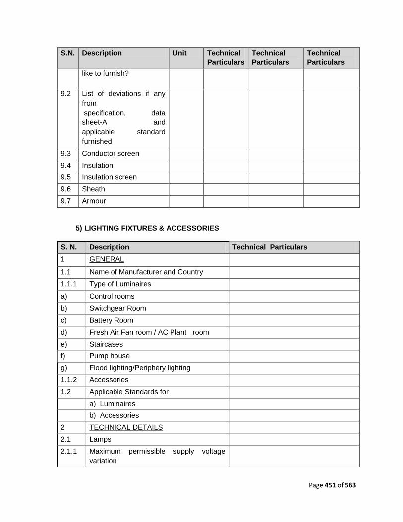
Page 451 of 563
S.N. Description Unit Technical
Particulars
Technical
Particulars
Technical
Particulars
like to furnish?
9.2 List of deviations if any
from
specification, data
sheet-A and
applicable standard
furnished
9.3 Conductor screen
9.4 Insulation
9.5 Insulation screen
9.6 Sheath
9.7 Armour
5) LIGHTING FIXTURES & ACCESSORIES
S. N. Description Technical Particulars
1 GENERAL
1.1 Name of Manufacturer and Country
1.1.1 Type of Luminaires
a) Control rooms
b) Switchgear Room
c) Battery Room
d) Fresh Air Fan room / AC Plant room
e) Staircases
f) Pump house
g) Flood lighting/Periphery lighting
1.1.2 Accessories
1.2 Applicable Standards for
a) Luminaires
b) Accessories
2 TECHNICAL DETAILS
2.1 Lamps
2.1.1 Maximum permissible supply voltage
variation
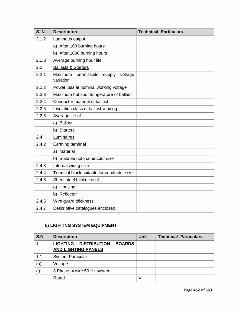
Page 452 of 563
S. N. Description Technical Particulars
2.1.2 Luminous output
a) After 100 burning hours
b) After 1000 burning hours
2.1.3 Average burning hour life
2.2 Ballasts & Starters
2.2.1 Maximum permissible supply voltage
variation
2.2.2 Power loss at nominal working voltage
2.2.3 Maximum hot spot temperature of ballast
2.2.4 Conductor material of ballast
2.2.5 Insulation class of ballast winding
2.2.6 Average life of
a) Ballast
b) Starters
2.4 Luminaires
2.4.2 Earthing terminal
a) Material
b) Suitable upto conductor size
2.4.3 Internal wiring size
2.4.4 Terminal block suitable for conductor size
2.4.5 Sheet steel thickness of
a) Housing
b) Reflector
2.4.6 Wire guard thickness
2.4.7 Descriptive catalogues enclosed
6) LIGHTING SYSTEM EQUIPMENT
S.N. Description Unit Technical Particulars
1 LIGHTING DISTRIBUTION BOARDS
AND LIGHTING PANELS
1.1 System Particular
(a) Voltage
(i) 3 Phase, 4 wire 50 Hz system
Rated V

Page 453 of 563
S.N. Description Unit Technical Particulars
Maximum V
One minute withstand voltage V
(ii) D.C. system
Rated V
(b) System short-circuit level
(i) At 415 V, A.C. kA
(rms)
(ii) At 110 V.D.C. kA
(D.C.)
(c) Reference ambient temperature deg C
1.2 Indicate the type and routine tests to be
carried out
1.3 Distribution Board/Panels
(a) Main, floor mounted distribution boards
(i) Main Lighting distribution board(A.C.)
Make
Type
Degree of protection
Bus bar material
Bus bar current rating A
Short circuit current rating kA
Details of Incoming and Outgoing feeders
Cable entry
Location
Each complete board/panel, LxWxD
Dimensional drawing enclosed
Indicate the type and routine tests to be
carried out
(ii) Emergency lighting panel (D.C.)
Make
Type
Degree of protection
Bus bar material
Bus bar current rating A
Short circuit current rating kA

Page 454 of 563
S.N. Description Unit Technical Particulars
Details of Incoming and
Outgoing feeders
Cable entry
Location
Each complete board/panel, LxWxD
Dimensional drawing enclosed
Indicate the type and routine tests to be
carried out
(iii) Three phase DBs, wall/structure mounting
SLDB for indoor area
Make
Type
Details of Incoming and Outgoing feeders
Degree of Protection
(iv) SLDB for outdoor area
Make
Type
Details of Incoming and Outgoing feeders
Degree of Protection
(v) Paint Finish
Colour shade
2
3 MINIATURE CIRCUIT BREAKER
3.1 Make
3.2 Type
4 EARTH LEAKAGE CIRCUIT BREAKER
4.1 Make
4.2 Type
4.3 Leakage Current I N mA
5 INSTRUMENT TRANSFORMERS
5.1 Make
5.2 Type
5.3 Output
5.4 Accuracy Class
6 METERS

Page 455 of 563
S.N. Description Unit Technical Particulars
6.1 Make
6.2 Type
6.3 Accuracy Class
7 RELAYS (IF ANY PROVIDED)
7.1 Make
7.2 Type
7.3 Voltage Rating V
7.5 Setting Range %
No. of Contacts
a)Normally open
b)Normally closed
8 FLAME PROOF ENCLOSURES
8.1 Make
8.2 Suitable for use in hazardous area
a)Area classification
b)Gases/Vapour group
8.3 Dimensional Drawings and Literature of
each required equipment flameproof
enclosure including fixing details enclosed
Yes/No
8.4 Approval certificates of relevant statutory
authorities enclosed
Yes/No
9 LIGHT CONTROL SWITCHES
19.1 Make
10 RECEPTACLE, PLUG AND SWITCH
10.1 Make
11 LIGHTING WIRES
11.1 Make
11.2 Applicable Standard
11.3 Voltage Grade V
11.4 Conductor Material Cu/Al
11.5 No.of Strands mm²
11.6 Colour Coding
12 CONDUITS
12.1 Make
12.2 Material

Page 456 of 563
S.N. Description Unit Technical Particulars
12.3 Finish (Galvanised/Black Enamel/Any
special anti-corrosive coating)
12.4 Sizes offered and wall thicknesses
1325 Supply of necessary couplings, bends,
tees, necessary for conduit routing
included
Yes/No
13 JUNCTION BOXES
13.1 Make
13.2 Material and Gauge
13.3 Painted / Galvanised
14 CEILING FANS
14.1 Make
14.2 Suspension Rod, Regulator and Switch
included
Yes/No
7) EARTHING & LIGHTNING PROTECTION SYSTEM
S.
No.
Description Material Technical Particulars
1 Main Earthing Grid
Quantity - As per
requirement
& Sizes – As per Fault
level calculations
a) Buried in earth MS
b) Buried in floor slabs in buildings MS
2 Conductor Leads To Equipment
(above ground) – Substation
Equipment & Structures
a) Circuit Breaker GS
b) Isolator GS
c) Transformers
(i) Transformer neutral to bottom of tank GS
(ii) From bottom of tank to earth grid GS
(iii) Transformer tanks and radiator bank GS
(iv) Marshalling Boxes GS
d) Lightning arrester GS
e) C.T. and P.T. body GS
f) C.T. and P. T. secondary terminal box GS

Page 457 of 563
S.
No.
Description Material Technical Particulars
g) Towers and structures GS
h) Fence posts and gates (Flex. braid) GS
i) 415V switchgear and capacitor panel GS
j) Motors
(i) 415V Motors above 10 kW GS
(ii)415V Motors up to 10 kW GI wire
(iii)Fractional horse power motors GI wire
k) Other Items
Capacitor panel, Battery charger panel,
Main lighting D.B, Control panels and
sub-lighting distribution boards
GS
Hand Rails GS
Cable trays GS
Tanks GS
Junction boxes GS
Lighting fixtures, receptacles, lighting
conduits
GS
Push button stations, limit switches GS
Crane rail GS
Street lighting, flood lighting poles and
junctions boxes
GS
Metallic non-current carrying structures GS
Lightning Conductors GS
Lightning protection down comers for
building
GS
Lightning protection horizontal roof
conductor for building
GS
Electrodes GS
Pipe electrode GS
Maintenance free electrode copper
8) ELEVATOR / ESCALATOR
1. Make

Page 458 of 563
2. Type - Standards
3. Capacity Kg
4. Rated speed M/sec.
5. Contract speed M/sec
6. Car dimensions (L X B X H) mm
7. Overall weight Kg.
8. Total Rise M
9. No. of Landings & Locations
10. Elevator control type
11. Operation
12. Levelling device
13. Type of car and landing doors
14. Size of doors mm x
mm
15. Door Operator
16. Vision panel in doors
17. Operating devices in car
18. Operating devices in landings
19. Indicating devices in car
21. Details of car lighting
22. Details of car ventilation
23. Details of Painting
24. Pit height from bottom landing mm
25.
Clearance between top landing and
Machine Room
mm
26 Machine Room Dimensions (L X B X H) mm
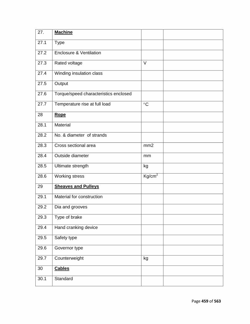
Page 459 of 563
27. Machine
27.1 Type
27.2 Enclosure & Ventilation
27.3 Rated voltage V
27.4 Winding insulation class
27.5 Output
27.6 Torque/speed characteristics enclosed
27.7 Temperature rise at full load C
28 Rope
28.1 Material
28.2 No. & diameter of strands
28.3 Cross sectional area mm2
28.4 Outside diameter mm
28.5 Ultimate strength kg
28.6 Working stress Kg/cm2
29 Sheaves and Pulleys
29.1 Material for construction
29.2 Dia and grooves
29.3 Type of brake
29.4 Hand cranking device
29.5 Safety type
29.6 Governor type
29.7 Counterweight kg
30 Cables
30.1 Standard

Page 460 of 563
30.2 Size mm2
30.3 Cores
30.4 No. of cables
No. of cable groups
9) DG SET
1.0 GENERAL
1.1 Name of manufacturer
1.2 Engine model no.
2.0 DESIGN FEATURES
2.1 Continuous site output rating at
generator terminals
kW
2.2 Site output rating after auxiliary power
consumption and transmission losses
at switchyard/ bus bar terminals
kW
2.3 Maximum site rating of engine (to be
not less than 110% of the value
indicated in item 2.1 above)
kW
2.4 Standard engine rating (i.e., under
standard atmospheric conditions as
per ISO : 3046)
kW
2.5 Derating factors for site conditions
applicable on standard engine rating :
%
a) Altitude %
b) Ambient temperature %
c) Relative humidity at inlet
temperature indicated in item (b)
above
%
d) Cooling water temperature at the
inlet of charge air cooler
%
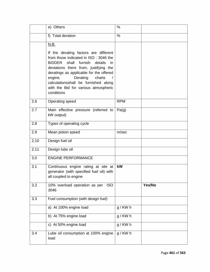
Page 461 of 563
e) Others %
f) Total deration %
N.B.
If the derating factors are different
from those indicated in ISO : 3046 the
BIDDER shall furnish details in
deviations there from, justifying the
deratings as applicable for the offered
engine. Derating charts /
calculationsshall be furnished along
with the Bid for various atmospheric
conditions
2.6 Operating speed RPM
2.7 Main effective pressure (referred to
kW output)
Pa(g)
2.8 Types of operating cycle
2.9 Mean piston speed m/sec
2.10 Design fuel oil
2.11 Design lube oil
3.0 ENGINE PERFORMANCE
3.1 Continuous engine rating at site at
generator (with specified fuel oil) with
all coupled to engine
kW
3.2 10% overload operation as per ISO
3046
Yes/No
3.3 Fuel consumption (with design fuel)
a) At 100% engine load g / KW h
b) At 75% engine load g / KW h
c) At 50% engine load g / KW h
3.4 Lube oil consumption at 100% engine
load
g / KW h

Page 462 of 563
3.5 Primary jacket water temperature at
engine inlet
oC
3.6 Primary jacket water temperature
engine outlet
oC
3.7 Secondary cooling water temperature
at heat exchangers inlet
oC
3.8 Secondary cooling water temperature
at inlet to cooling tower,
oC
3.9 Secondary cooling water flow m3/hr.
3.10 Maximum Secondary Water pressure
drop through heat exchanger at flow
value indicated in 3.9 above
Pa
3.11 Secondary cooling water pressure at
heat exchanger inlet
Pa
3.12 Lube oil temperature at lube oil cooler
outlet
oC
3.13 Lube oil temperature at lube oil cooler
inlet
oC
3.14 Maximum period for which engine can
operate without cooling water c
a) During cold start of engine Secs.
b) During hot start of engine Secs.
3.15 Flue gas analysis at 100% load for
specified fuel :
a) SO2
b) Nox
c) Hydro carbon
d) CO2
e) CO
f) Particulate matter

Page 463 of 563
g) Others
h) SO2 through stack Kg/hr
3.16 Governing Characteristics
3.16.1 Maximum step load that can be
applied to the engine at full rated
speed, no load and at normal running
temperatures
% of rated
load
3.16.2 Transient speed change resulting from
applications of the load indicated in
item 3.16.1 above
% of rated
load
3.16.3 Permanent speed change resulting
from application of the load indicated
in item 3.16.1 above
% of rated
load
3.16.4 Maximum recovery time to permanent
speed change of 3.16.3
Secs.
3.16.5 Transient speed rise resulting from a
full load throw-off
% of rated
load
3.16.6 Permanent speed rise resulting from a
full load throw-off
% of rated
load
3.16.7 Maximum recovery time to reach
permanent speed rise value indicated
in item 3.16.6 above
Secs.
3.16.8 Transient speed change resulting from
a change of load, both ON and OFF,
by any step of 25% of the rated full
load
% of rated
load
3.16.9 Permanent speed change resulting
from change of load, both ON and
OFF, by any step of 25% of the rated
full load
% of rated
load
3.16.10 Recovery time for attaining permanent
speed change value indicated in item
3.16.9
Secs.
3.16.11 Steady load speed band % of rated

Page 464 of 563
load
3.17 DG set starting time i.e., ready to take
load after ―start‖ impulse
Secs.
3.18 Maximum noise level at
………….metres from equipment
outline
dBA
3.19 Maximum vibration level (peak to
peak)
mm/secs.
4.0 GENERATOR PERFORMANCE
4.1 Generator efficiency at 100% rated
load
%
4.2 Generator efficiency at 75% rated load %
4.3 Generator efficiency at 50% rated load %
4.4 Generator efficiency at 25% rated load %
4.5 Voltage regulator response %
4.6 Excitation at full load and under
specified variation of voltage and
speed
5.0 ENGINE CONSTRUCTION
FEATURES
5.1 Engine model No.
5.2 No. of strokes Two / Four Strokes
5.3 No. of cylinders
5.4 Arrangement of cylinders Inline / Vee Type
5.5 Cylinder bore mm
5.6 Piston stroke mm
5.7 Compression ratio
5.8 Cylinder block :
a) Material of construction

Page 465 of 563
5.9 Crank case :
a) Material of construction
5.10 Cylinder head :
a) Material of construction
5.11 Cylinder liner :
a) Material of construction
5.12 Crank shaft :
a) Forged / cast
b) Material of construction
5.13 Crank shaft main bearings:
a) Nos. provided
b) Material of construction
5.14 Piston :
a) Type
b) Material of construction
5.15 Piston rings:
a) Material of compression rings
b) Material of oil rings
5.16 Piston pin (Gudgeon pin):
a) Material of construction
5.17 Connecting rod :
a) Material of bearings
b) Lining for bearing materials
5.18 Camshaft:
a) Material of bearings and lining
details
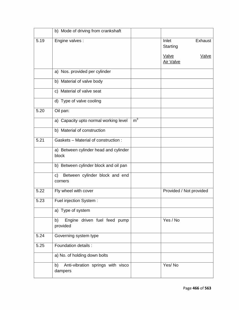
Page 466 of 563
b) Mode of driving from crankshaft
5.19 Engine valves : Inlet Exhaust
Starting
Valve Valve
Air Valve
a) Nos. provided per cylinder
b) Material of valve body
c) Material of valve seat
d) Type of valve cooling
5.20 Oil pan:
a) Capacity upto normal working level m3
b) Material of construction
5.21 Gaskets – Material of construction :
a) Between cylinder head and cylinder
block
b) Between cylinder block and oil pan
c) Between cylinder block and end
corners
5.22 Fly wheel with cover Provided / Not provided
5.23 Fuel injection System :
a) Type of system
b) Engine driven fuel feed pump
provided
Yes / No
5.24 Governing system type
5.25 Foundation details :
a) No. of holding down bolts
b) Anti-vibration springs with visco
dampers
Yes/ No

Page 467 of 563
6.0 ENGINE SYSTEMS
6.1 Fuel Oil system :
a Fuel Oil tanks ( For each tank )
a) Nos. provided
b) Working capacity of each tank m3
c) Size of tank :
i) Rectangular tank mxmxm
ii) Cylinder tank Dia(m)xHt(m)
d) Material of construction
e) Location
b Motor operated transfer pumps
furnished
Yes / No
( For each pump )
a) Nos.
b) Type
c) Capacity m3/hr.
d) Motor Rating KW
c Fuel oil filters 2 x 100 % Simplex / 1 x
100 % Duplex
d Maximum pressure drop across filters
in clogged condition
e Through put capacity of fuel oil
treatment plant at specified viscosity of
fuel oil
f No. of fuel oil treatment units provided.
g Separating temperature
6.2 Lube oil System :

Page 468 of 563
a Type and grade of lube oil to be used
b Capacity of lube oil sump below
cylinder block / crane case at normal
working level
m3
c Lube oil tanks external to engine ( For
each tank )
Yes / No
d a) Capacity m3
e b) Material of construction
f c) Location
g Engine driven / Motor Driven lube oil
pump :
a) Nos.
b) Type
c) Capacity m3/hr.
d) Motor Rating KW
h Lube oil cooler :
a) Type
b) Cooling fluid
c) Secondary Cooling Water flow
/ Primary
Jacket Water flow
m3/hr.
i Lube oil filters :
a) Type 2 x 100 % Simplex / 1 x
100 % Duplex
b) Maximum allowable pressure drop
across filter
in clogged condition
j Lube oil heater :
a) Provided Yes/ No

Page 469 of 563
b) Type
c) If electric, indicate power rating kW
k AC motor driven priming pump :
a) Nos. provided
b) Type
c) Capacity m3/hr.
d) Head mlc
e) Motor rating kW
l Quantity of lube oil required for initial
filling
m3
m Through put capacity of lube oil
treatment plant at specified viscosity of
fuel oil
n No. of lube oil treatment units
provided.
o Separating temperature
6.3 Primary Jacket Water System
a Type of cooling Radiator cooled /
Secondary cooling water
cooled
b Quality of water
c Quantity of water required for initial
filling
m3
d Makeup water quantity m3/hr.
e Expansion tank :
a) Working capacity m3
b) Size :
i) Rectangular mxmxm

Page 470 of 563
ii) Cylindrical Dia(m)xHt(m)
c) Material of construction
d) Inner coating details
f Jacket Water Pump and jacket water
pre heating pump
a) Type Engine driven / AC
motor driven
b) Capacity m3/hr.
c) Head mlc
d) Mode of driving off engine crank
shaft
e) Motor Rating KW
g Radiator (if required)
a) Type
b) Overall size
c) Materials of construction :
i) Tubes
ii) Fins
iii) Header
d) Location
e) Radiator fan :
i) Tip diameter mm
ii) Max. speed rpm
iii) Flow at above speed m3/hr.
f) Air temperature rise across radiator
g) Mode of drive from engine crank
shaft

Page 471 of 563
h) Material of construction of fan :
i) Blades
ii) Hub
i) Air ducting details :
i) Material of construction
ii) Inside clear dimensions mmxmm
iii) Type of fixing arrangement
between air duct and radiator
j) Fan guard provided Yes / No
k) Fan motor rating KW
h Heat Exchanger :
a) Designation
b) Type Shell & tube type / plate
type
i Jacket water heater :
a) Nos. provided
b) Type
c) If electric, power required kW
6.4 Air intake system :
a Intake silencer type
b Air cleaner :
a) Type Wet/ Dry
b) Nos. provided
c) Design air flow m3/hr.
d) Materials of construction:
i) Body and cover

Page 472 of 563
ii) Filter element
e) Type of oil to be used for wet type
f) Frequency of oil cleaning filter
element cleaning
g) Location
c Turbocharger (exhaust gas driven) :
a) Speed Rpm
b) Air pressure at outlet Pa(g)
c) Air temperature at outlet oC
d) Maximum air flow Nm3/hr.
e) Blade material
f) Casing material
d Supercharger (engine driven) :
a) Type Roots type
b) No. of lobes Two / Three
c) Speed rpm
d) Air flow Nm3/hr.
e) Air outlet pressure Pa(g)
f) Air outlet temperature oC
g) Material of construction :
i) Lobes
ii) Casing
iii) Shafts
iv) Bearings
v) Seals
vi) Timing gears

Page 473 of 563
b) Type of drive from engine crank
shaft
e Charge air cooler :
a) Type
b) Nos. provided
c) Cooling water type
d) Design water flow required m3/hr.
e) Pressure drop at above flow mlc
f) Inlet water temperature oC
g) Temperature rise oC
h) Charge air temperature at cooler
outlet
oC
i) Material of construction :
i) Tubes
ii) Fins
iii) Cover
iv) End plates
6.5 Exhaust gas system:
6.5.1 No. of streams provided
6.5.2 Exhaust silencer
a) Nos. provided per exhaust pipe
b) Type
c) Location
6.5.3 Exhaust Duct
a) Size
b) Material

Page 474 of 563
6.5.4 Lagging details :
a) Lagging material
b) Lagging thickness
6.6 Air starting system :
6.6.1 Nos of compressors motor driven
6.6.2 Nos of compressors diesel engine
driven
6.6.3 Compressor details
a) Manufacturer
b) Type
c) Rating
d) Speed rpm
6.6.4 Air receivers / air bottles
a) Nos. provided
b) Air capacity of each air receiver m3
c) Normal air pressure in air receiver Pa(g)
d) No. of starts of engine from each
receiver
6.6.5 Normal air pressure for starting Pa(g)
6.6.6 Minimum air pressure for starting
engine
Pa(g)
6.6.7 Quantity of free air per start Nm3/hr.
6.7 Common base frame for engine and
generator:
Type
Material of construction
6.8 Engine generator coupling :

Page 475 of 563
a Type
b Whether fixed directly to fly wheel : Yes / No
c Clutch with engaging / disengaging
arrangement provided?
Yes / No
d Coupling guard material
e Coupling guard for clutch provided ?
If ‗Yes‘ indicate type
Yes / No
7.0 GENERATOR AND ACCESSORIES
7.1 Name of manufacturer
7.2 Design rating kW
7.3 Continuous output rating kW
7.4 Maximum rating kW
7.5 Power factor
7.6 Rated voltage Volts
7.7 Rated current/ phase Amps
7.8 Speed rpm
7.9 Frequency C/s
7.10 Field current at rated output and
voltage
Amps
7.11 Insulation class :
a) Stator
b) Rotor
7.12 Temperature rise above ambient of
45oC (by thermometer):
a) Stator oC
b) Rotor oC
c) Cores oC

Page 476 of 563
7.13 WR2 of rotating mass in diesel engine,
generator, exciter, etc.
kgm2
7.14 Generator parameters :
7.14.1 Synchronous reactance Xd:
a) Unsaturated Ohms
b) Saturated Ohms
7.14.2 Transient reactance X‘d:
a) Unsaturated Ohms
b) Saturated Ohms
7.14.3 Sub-transient reactance X‖d:
a) Unsaturated Ohms
b) Saturated Ohms
7.14.4 Zero sequence reactance Xo Ohms
7.14.5 Negative sequence reactance X2 Ohms
7.14.6 Open circuit transient time constant secs.
7.14.7 Open circuit synchronous time
constant
secs.
7.14.8 Open circuit field time constant T secs.
7.14.9 Short circuit ratio
7.14.10 Resistance of field winding at
operating temperature
Ohms
7.14.11 Resistance of stator winding at
operating temperature
Ohms
7.15 Generator performance :
7.15.1 Full load losses kW
7.15.2 Armature copper loss kW
7.15.3 Rotor copper loss kW

Page 477 of 563
7.15.4 Core loss kW
7.15.4 Stray losses kW
7.15.5 Efficiency :
a) ¼ load %
b) ½ load %
c) 3/4 load %
d) Full load %
8.0 MAIN EXCITER
8.1 Rated voltage Volts
8.2 Rated current Amps
8.3 Ceiling voltage at zero load and rated
speed
Volts
8.4 Ceiling voltage at rated current and
rated speed
Volts
8.5 Excitation system response ratio
8.6 Insulation class:
a) Stator
b) Rotor
9.0 AUTOMATIC VOLTAGE
REGULATOR
9.1 Type
9.2 Burden of AVR on CTs and PTs
a) CTs Va
b) PTs Va
9.3 Dead band (if any)
9.4 Field discharge resistor Ohms
9.5 Type and rating of field breaker

Page 478 of 563
10 TESTING
10.1 BIDDER to indicate whether the
following tests will be conducted :
10.2 Dimensional accuracy of individual
components
Yes / No
10.3 Hydro testing of all jacket water
passages
Yes / No
10.4 Hydro testing of all lube oil lines Yes / No
10.5 Hydro testing of fuel oil lines Yes / No
10.6 Checking all lube oil passage for free
flow of oil
Yes / No
10.7 Rig testing of governor assembly Yes / No
10.8 Rig testing of individual injectors Yes / No
10.9 Shop testing of engine with all the
engine driven equipment in position
Yes / No
11 WEIGHTS
11.1 Weight of fully assembled engine kg
11.2 Weight of generator kg
11.3 Weight of common base frame kg
11.4 Weight of fully assembled engine
generator
kg
11.4 GD2 for DG set Kg/m2
11.5 Weight and name of heaviest part to
be lifted during :
a) Erection
b) Maintenance
kg
12 DIMENSIONS
12.1 Overall dimension of engine
12.2 Overall dimension of generator

Page 479 of 563
12.3 Height and name of longest part to be
lifted during maintenance
6.2 HVAC
6.2.1 TUBE AXIAL FANS
Sr. No. Description Requirement
1. Room Designation Lift well, Lift lobby & Staircase pressurization
fans
2. Location Fan room on Terrace Level
3. Numbers required 10 Nos.
(All 10 W – Fire Mode)
4. Location/ Duty Outdoor/ fire emergency
5. Type/Tentative Capacity (each)
Tube axial fan/ 19000 CFM(Lift well), 19500
CFM(Lift lobby) & 28000 CFM (Staircase) at
25 mmWC static pressure / 1450 rpm.
6. Designed condition of
Air at fan suction Dry Bulb temp.: 45.0 ºC
7. Drive/ Mounting type Direct/ Mounted in Indoor Cabinet
8. Material–Casing/ Impeller/ Shaft CS/ (CS/ CAST AL)/ EN8
9. Fire rating Fan shall withstand Temperature of 250ºC for
2 Hrs.
10 Design/Testing/ Inspection As per IS 2312, IS 3588, AMCA 203, AMCA
210, AMCA 300, IS 4894
6.2.2 VANE AXIAL FAN
Sr. No. Description Requirement
1. Room Designation Basement ventilation
2. Location At exhaust air cutout in Basement

Page 480 of 563
3. Numbers required 4 Nos.
(2 W – Normal mode; 2 W – Fire Mode)
4. Location/ Duty Basement / Normal mode 6 ACPH & Fire
mode 12 ACPH.
5. Type/ Capacity (each)
Vane axial type smoke spill Fans, 11000
CFM at 25 mmWC static pressure / 1450
rpm.
6. Designed condition of Air at
Outdoor fan suction Dry Bulb temp.: 45.0 ºC
7. Drive/ Mounting type Belt driven / Mounted in Indoor Cabinet
8. Material–Blades/ Hub Aluminum
9. Design/Testing/ Inspection As per IS 2312, IS 3588, AMCA 203,
AMCA 210, AMCA 300, ACMA 204-05
6.2.3 PROPELLER FAN
Sr. No. Description Requirement
1 Room Designation Pump room Electrical room
2 Location Basement At Each Floor
3 Numbers required 1 10
4 Location/ Duty On external Wall / Intermittent
5 Type/Speed/Static Propeller fan/1400 RPM/15 mmWC static pressure
6 Capacity (CFM) 2000 1250

Page 481 of 563
6.2.4 CABINET TYPE CENTRIFUGAL FANS
Sr. No. Description Requirement
1. Room Designation Toilet ventilation
2. Location At Terrace
3. Numbers required 2 Nos. (9000 CFM & 11000 CFM)
4. Location/ Duty Terrace/ centralized toilet exhaust fan.
5. Type/ Capacity (each)
Cabinet type smoke spill centrifugal Fans,
11000 CFM and 9000 CFM at 25 mmWC
static pressure / 1450 rpm.
6. Designed condition of Air at
Outdoor fan suction Dry Bulb temp.: 45.0 ºC
7. Drive/ Mounting type Belt driven / Mounted in Indoor Cabinet
8. Material–Blades/ Hub Aluminum
9. Design/Testing/ Inspection As per IS 2312, IS 3588, AMCA 203,
AMCA 210, AMCA 300, ACMA 204-05
6.3 FIRE FIGHTING
1. Electrical Driven Main Fire Pumps
7
Designed condition
of Air at Outdoor
fan suction
Dry Bulb temp.: 40.0 ºC
8 Drive/ Mounting
type Direct/ On external Wall
9 Material – Blades/
Hub Aluminum
10 Design / Testing/
Inspection
As per IS 2312, IS 3588, AMCA 203, AMCA 210, AMCA
300, ACMA 204-05

Page 482 of 563
Make / Manufacturer :
Quantity :
Liquid Handed :
Liquid Temp deg.C :
Special Gravity of Liquid :
Suction :
Rated Discharge :
Actual Discharge :
Model :
Horizontal / Design :
Speed / No. of Stages :
Impeller Dia (Maximum) :
Suction / Delivery Size :
Efficiency at Rated Capacity & Head :
KW required at rated capacity & head :
Shut Off Head :
Material of Construction
Pump Casing :
Impeller :
Pump Shaft :
Shaft Sleeve :
Casing Wearing Ring :
Base Plate :
Mechanical Seal :
Make of Mechanical Seal :
Wheather pumps is capable of

Page 483 of 563
discharging 150% of rated capacity at a
head not less than 65% of rated head. :
Whether automatic priming arrangement
Included :
Description of Motors
Make :
Model No. :
Type :
Frame size :
Speed (RPM) :
Rated Capacity (Power) :
Full load current :
Enclosure :
Coupling / Pulley :
Class of Insulation :
Size of Foundation :
For complete coupled set mounted over
MS base frame :
2. Diesel Engine Driven Pump
Make / Manufacturer :
Quantity :
Liquid Handed :
Liquid Temp deg.C :
Special Gravity of Liquid :
Suction :
Rated Discharge :

Page 484 of 563
Actual Discharge :
Model :
Horizontal / Design :
Speed / No. of Stages :
Impeller Dia (Maximum) :
Suction / Delivery Size :
Efficiency at Rated Capacity & Head :
KW required at rated capacity & head :
Shut Off Head :
Material of Construction
Pump Casing :
Impeller :
Pump Shaft :
Shaft Sleeve :
Casing Wearing Ring :
Base Plate :
Mechanical Seal :
Make of Mechanical Seal :
Wheather pumps is capable of
discharging 150% of rated capacity at a
head not less than 65% of rated head. :
Whether automatic priming arrangement
Included :
Description of Engine
Make :
Model No. :

Page 485 of 563
Type :
Frame size :
Speed (RPM) :
Rated Capacity (Power) :
Full load current :
Enclosure :
Coupling / Pulley :
No of Cylinder :
Fuel Pump & Water pump detail :
Engine Cooling & Oil System :
Diesel Oil tank capacity :
Fuel Oil storage shall ensure working of
pump for number of hours :
Size of Foundation
For complete coupled set mounted over
MS base frame :
3 Jockey Pump
(Please submit separate data sheet for each type of pump)
Liquid Handed :
Liquid Temp deg.C :
Special Gravity of Liquid :
Suction :
Rated Discharge at Low Zone Head :
Rated Discharge at High Zone Head :
Actual Discharge at Low Zone Head :

Page 486 of 563
Actual Discharge at High Zone Head :
Model :
Horizontal / Design :
Speed / No. of Stages :
Impeller Dia (Maximum) :
Suction / Delivery Size :
Efficiency at Rated Capacity & Head :
KW required at rated capacity & head :
Shut Off Head : :
Material of Construction
Pump Casing :
Impeller :
Pump Shaft :
Shaft Sleeve :
Casing Wearing Ring :
Base Plate :
Mechanical Seal :
Make of Mechanical Seal :
Description of Motor
Make :
Model No. :
Type :
Frame size :
Speed (RPM) :
Rated Capacity (Power) :
Full load current :

Page 487 of 563
Enclosure :
Coupling / Pulley :
Size of Foundation
For complete coupled set mounted over MS
base frame :
4. PIPING
15 NB TO 50 NB :
15 TO 50 NB Fittings :
65 NB TO 150 NB Pipes :
65 NB TO 150 NB Fittings :
200 NB ONWARDS Pipes :
200 NB ONWARDS Fittings :
Flanges :
Gaskets :
5. HYDRANT VALVES
Technical Specifications :
Make :
Working Pressure :
Code for Design Mft. :
Construction Features
Type of Stem :
Type of Inlet :
Type of Outlet :
Flange Drilling :
Material of Construction
Body and Bonnet :

Page 488 of 563
Stop Valve, Valve Seat :
Check nut & gland nut :
6. PRESSURE GAUGE
Technical Specifications :
Make :
Working Pressure :
Code for Design Mft. :
Scale range :
Construction Features
Case :
Pointer :
Dial Size :
Dial Lettering :
Process Connection :
Material of Construction
Case :
Movement :
Block :
7. PRESSURE SWITCHES
Technical Specifications
Make :
Working Pressure :
Scale range :
Construction Features
Protection :
Cable Entry :

Page 489 of 563
Process Connection :
Repeatability :
Switch :
Type : :
No. of contacts :
Contact Rating :
Material of Construction
Enclosure :
Pressure element :
Wetted Parts :
8. ELECTRICAL ACCESSORIES
MAKE OF THE FOLLOWING
a. Motor Control Centre (Electrical Panel) :
b. Vacuum circuit breaker :
c. Air circuit breaker :
d. MCCB :
e. MCB :
f. Rotary switch :
g. Soft Starter :
h. Auto-transformer Starter :
j. Automatic Star Delta Starter :
k. Direct on line Starter :
l. Contactor :
m. Current Transformer (cast resin type) :
n. Single phase preventor :

Page 490 of 563
o. Push Button :
p. Change over switch :
q. Ammeter & Voltmeter :
KWH meter
r. Relay :
s. Indication lamp :
t. Cables :
u. Wires :
v. Variable Frequancy Drive. :
CHAPTER 7 LIST OF APPROVE MAKES
7.1 ARCHTECTURE
Sr. No. Product Manufacturer‟s Name
1. AAC / flyash blocks Charbuja, Aerocon, Siporex, Ecolite, CEEFpro,
BLIT or other equivalent make approved by
BSCDCL
2. Waterproofing
Treatment
Pidilite, BASF or equivalent approved by
BSCDCL
3. GRC Unistone, Birla White or other equivalent make
approved by BSCDCL
4. Concrete, Stone Sealar Degussa, Wacker, Hytek, Aquamix, Laticrete,
Kerakoll
5. Fire Check Wood, Steel
Doors
Signum, Godrej, Guardian, Navair, Shakti
Hormann, Promat, Alhada,
6. Flush Doors Tata Conswood, Greenwood, Garnet, Merino,
Century or other equivalent make approved by
BSCDCL
7. Door seals [ dust / fire ] Lorient, Enviroseals, Pemko, Assorted

Page 491 of 563
Sr. No. Product Manufacturer‟s Name
8. Structural, Weather
Sealant
Dow Corning, GE, Dupont
9. Glazed, Ceramic &
Vitrified Tiles
Euro, Oriental Bell, Kajaria, Nitco, Jhonson,
RAK or other equivalent make approved by
BSCDCL
10. Pigmented Joint fillers Laticrete, Pidilite
11. Tensile Roof Unique, Ecostructures, Ferari
12. Cement Putty Birla White, J K white or other equivalent make
approved by BSCDCL
13. Paint Nerolac, Asian Paints, Dulux, Jenson &
Nicholson, Berger, ICI, Oikos, Akzonobel, MRF
14. Glass Saint Gobain, AIS, Pilkington, Emirates
15. Glazing Systems Hydro, Domal, Kawneer
16. Fire rated glass Schott, Saint Gobain
17. Doors, Window Fittings
And Fixtures
Dorma, Giesse, Dline, Union, Yale, Assa Abloy
brands
18. Toughening Agencies Sejal, GSC, Gold Plus, Impact
19. Lamination Films Garware, Dupont or other equivalent make
approved by BSCDCL
20. Polycarbonate sheet Lexan, Danpalon, GE, Tuflite, Plaram
21. Gypsum & Mineral
Fibre boards, systems,
access panels &
accessories
Saint Gobain, India Gypsum, Rondo,
Armstromg, AMF, Knauf, Rehau, Lafarge,
Gypsemma, USG
22. False Floor Unitile, Solidfeel
23. Handrails Technorails, Dline, Dorma, Carlf India,
24. Toilet Modular
Partitions
Merino, or equivalent approved by BSCDCL

Page 492 of 563
Sr. No. Product Manufacturer‟s Name
25. Acoustic treatment /
boards, etc
Anutone
26. Fencing A1Fence or other equivalent make approved by
BSCDCL
27. Polypyopylene Rungs Pranali, Mase Safety Works, StepX
28. Paver Blocks Basant Beton, Vyara or other equivalent make
approved by BSCDCL
29. Curb Stone Super Tiles or other equivalent make approved
by BSCDCL
30. Thermoplastic Road
Marking Paint
Asian Paint PPG-Apcomark, Automark
Technologies (India) Pvt. Ltd. or other
equivalent make approved by BSCDCL
31. Fire Stop Mortar &
Foam
Firestop, Hilti, Promat, Newkem
32. Expansion Joints CS expansion joints, BASF Eabco, Excel Tech
33. Cast in Channels Halfen Deha, Jordhal
34. Sanitary wares Hindware, Parryware, Cera, HR Jhonson,
Jaquar or other equivalent make approved by
BSCDCL
35. Concealed flush tanks /
valves
Gebrit, Jaquar, Schell, Commander, Viega,
Parryware
36. Faucets /sanitary
fittings
Jaquar, Grohe, Schell, Hindustan, Hindware or
other equivalent make approved by BSCDCL
37. HDPE drain boards Doerken, Green global, Pidilite
38. CPVC plumbing pipes &
adhesives
Flowgaurd, Astral ,Ashirwad, Prince
39. Manhole covers Neco, Municast,
40. Gate automation &
control
Gandhi automation, Boon Edam

Page 493 of 563
Sr. No. Product Manufacturer‟s Name
41. Anchor Fastener Fischer, Hilti
42. Entry Mat Euronics, 3M
43. Stamp Concrete Unistone, Bromanite
Sr. No. Product Manufacturer‟s Name
44. AAC / flyash blocks Charbuja, Aerocon, Siporex, Ecolite, CEEFpro,
BLIT or other equivalent make approved by
BSCDCL
45. Waterproofing
Treatment
Pidilite, BASF or equivalent approved by
BSCDCL
46. GRC Unistone, Birla White or other equivalent make
approved by BSCDCL
47. Concrete, Stone Sealar Degussa, Wacker, Hytek, Aquamix, Laticrete,
Kerakoll
48. Fire Check Wood, Steel
Doors
Signum, Godrej, Guardian, Navair, Shakti
Hormann, Promat, Alhada,
49. Flush Doors Tata Conswood, Greenwood, Garnet, Merino,
Century or other equivalent make approved by
BSCDCL
50. Door seals [ dust / fire ] Lorient, Enviroseals, Pemko, Assorted
51. Structural, Weather
Sealant
Dow Corning, GE, Dupont
52. Glazed, Ceramic &
Vitrified Tiles
Euro, Oriental Bell, Kajaria, Nitco, Jhonson,
RAK or other equivalent make approved by
BSCDCL
53. Pigmented Joint fillers Laticrete, Pidilite
54. Tensile Roof Ferrari, Mehler,
55. Cement Putty Birla White, J K white or other equivalent make
approved by BSCDCL
56. Paint Nerolac, Asian Paints, Dulux, Jenson &

Page 494 of 563
Sr. No. Product Manufacturer‟s Name
Nicholson, Berger, ICI, Oikos, Akzonobel, MRF
Note : Bidders to consider any of the approved makes indicated above. If any equivalents
are suggested by the bidder, they shall be specifically highlighted in the bid submissions,
along with technical documentation supporting compliance / equivalency.
7.2 LANDSCAPE
Sr. No. Product/ Equipment Manufacturer‟s Name
1. Irrigation System RAINBIRD- Harvel Irrigations Pvt. Ltd.
JAIN IRRIGATION SYSTEMS LTD.
PREMIER WORLD
2. Gunmetal And Brass Valves ZOLTO
LEADER
SANT
3. PVC Pipes And Fittings FINOLEX
SUPREME
PRINCE
4. Stamped Concrete UNISTONE, BROMANITE
5. Terrace Garden Composite System
(includes drainboard, geotextiles,
secondary waterproofing if required )
STP
CICO
6. Fountain System
RIPPLE FOUNTAINS
PREMIER FOUNTAINS
DEEP- N - DEEP
7. Curb Stone SUPER TILES
7.3 CIVIL & STRUCTURAL
Sr. No. Category Sub Category Brand Name
1 Cement OPC 43/53 Grade(ISI
marked), PPC
Ambuja Cement, L & T, ACC,
Birla, VIKRAM, J.K., Ultratech,
Grasim, Binani, India cement
3 Cement White Cement Ultra tech, ACC, Birla ,J.K,

Page 495 of 563
Sr. No. Category Sub Category Brand Name
4 Cement Chemical Admixtures
Kerakoll, MC Bauchemie,
BASF, MYK Schomburg,
Pidilite, Sunanda Chemicals,
Sika, FOSROC, Choksey
Chemicals
5 Cement Expansion joint board Supreme Industries or
equivalent
6 Steel Rebars Vizag Nigam Ltd., SAIL
7 Steel Structural Steel
Vizag,TISCON, SAIL, Metro
structure, RINL,AGRASEN
ISPAT,JSW, CORUS
8 Steel HYSD Bars Metro HSDS bars
9 Steel TMT Bars
Thermex TMT, Goel TMT,
Nakoda TMT or equivalent
approved by BSCDCL
10 Steel M.S. Pipe, Tubes, Bar,
Flats,Angle, Tee Sections SAIL ,TISCO
11 Masonary
Work AAC blocks
BILT Industries Pvt. Ltd,
Aerocon, Siporex India limited,
Xtralite; Pragya Marketing Co.
ltd
12 Water Proofing Water proofing compound CICO, Pidilite, Laticrete
13 Water Proofing Membrane Waterproofing
system
BASF, STP limited, Texsa, W
R Grace
14 Water Proofing Chemical Waterproofing
system
BASF, MC-Bauchemie, Sika,
Sunanda Specialty Coatings,
Perma Construction Aid Pvt.
Ltd.
15 Water Proofing Water stops Hydrotite, BASF, Hydroswell
16 Ready Mix
Concrete Ready Mix Concrete
ACC, RMC, Ultra tech or
installed batch mix plant at site
17 Miscellaneous Structural Sealant Wacker, Dow Corning, GE

Page 496 of 563
Sr. No. Category Sub Category Brand Name
18 Miscellaneous Polysulphide sealant Pidilite, Chemetall-Rai
19 Miscellaneous Bitumen Impregnated
Board Shalitex
20 Miscellaneous Polyethylene back up rod Supreme Ind. Ltd.
21 Miscellaneous Epoxy Fosroc/ STP/ CICO/ Ardex
22 Miscellaneous Welding rod ADVANI
23 Miscellaneous Shear Stud/Connector KOCO
24 Miscellaneous Clamp,Rebar,Chemcial
fastner Hilti,Fischer,Wurth
26 Miscellaneous Anchor Fasteners / bolts Hilti, Fischer, Halfen
27 Miscellaneous Masking Tapes 3M, Sun Control/ Wonder
Polymer
28 Miscellaneous Dash Fasteners SS grade, Hilti/
29 Miscellaneous Stainless Steel Bolts,
Washers and Nuts Kundan/ Puja/ Atul
30 Miscellaneous Stainless Steel Pressure
Plate Screws Kundan/ Puja/ Atul
31 Miscellaneous Stainless Steel Friction
Stay Hetish, Haffle, Securistyle
32 Miscellaneous Weather Silicon make
and grade Dow Corning/ Momentive (GE)
33 Miscellaneous Structural Silicon Dow Corning/ Momentive (GE)
34 Miscellaneous Tensile fabric System Ferrari, Mehler, MakMax, Akruti
35 Miscellaneous Stainless Steel Jindal/ SAIL/ Golden
36 Miscellaneous Polycarbonate Sheet
Danpalon,Alcox, Polygal,V. A.
Corporation, Joy Fab, Yadav
Engineering
37 Miscellaneous Adhesives & Grouts Bal, Laticrete, KeraKoll, Pidilite

Page 497 of 563
7.4 ELECTRICAL
Sr. No. Material/ Equipment Vendor
1. Protection Relays (Numeric / Electro mechanic
Type)/ Auxiliary relays)
ABB
Schneider Electric
Siemens
Alstom
GE
2. Potential & control Transformer (CT/PT) Automatic Electric
Gilbert & Maxwell
Kappa
Pragati
Anant powertech
3. Current Transformer (Cast Resin Epoxy
Coated)
Automatic Electric
Gilbert & Maxwell
Kappa
Pragati
Anant powertech
4. Electronic Digital Meter (A/V/PF/HZ/KWH)
/MFM with LCD/LED Display.
Schneider
Siemens
Socomec
L & T
Secure
5. HRC Fuse and Fuse Fitting ABB
GE
Siemens
L&T
6. ACB / MCCB/ Contactors ABB
Schneider
Siemens
L&T
7. Change over switch (automatic/ manual) HPL
Hager
Socomec
GE
8. Thermister relay Alstom/ Minilec/ Siemens
9. Push Buttons ABB
L&T
Schneider
Siemens
BCH
10. A. Power Distribution Panels & Boards
Totally Type Tested Assembly (TTA)
(AS PER IEC61439- 1 & 2).
Advance
Panels &
switchgears

Page 498 of 563
To be sourced directly from OEM or authorized
licensed partner. To be manufactured at
manufacturer‘s own factory.
(P) Ltd.
Adlec Power Pvt Ltd.
Jakson
C&S Electric limited
11. Switches, Time Delay Relay Schneider
Siemens
Hager
Legrand
12. Indicating Lamps Siemens
Schneider
ABB
L&T
BCH
Esbee
13. LT Power Cables Universal
NICCO
KEC International
Finolex
CCI
Gloster
14. Control Cables Universal
NICCO
KEC International
Finolex
CCI
LAPP India
Gloster
15. HT/ LT Jointing Kit & Termination Kits Birla-3M
Raychem
M seal
16. Termination (Lugs)/ Cable Glands(Double
compression )
Commet
Dowell
Jainson
17. Selector Switches Kaycee
ABB
Siemens
Schneider
18. Alarm Annunciators (solid state type with LED
illumination) / Facia Annunciator
Industrial Instruments & Controls
Minilec
Alstom
ICA

Page 499 of 563
19. Cable Management Systems-Raceways/Floor
Boxes/ Trunkings , Cable trays
Legrand
OBO-Betterman
MEM
20. Cable tray hangers and Supports Gripple
Hilti
21. MS Black Stove Enameled ERW Conduits/GI
pipes(ISI Approved) & accessories
AKG
BEC
Precision
RMCON
22. UPVC Conduit/JB/flexible conduit / tees/
Bevels, elbow & accessories
AKG
Plaza
Avon Plast
Precison
23. Copper Conductor PVC Insulated Wires/
Stranded Flexible Wires (FRLS) (including
panel wiring)
Finolex
RR Kabel
KEI
Havells
LAPP India
24. Non-insulated Copper Earthing conductors Gupta Industrial Corporation
(Vasai, Palghar)
Bharat Wires & Ropes
Diamond Cables
25. Modular Switches, Socket Outlets And Wiring
Accessories With Moulded Cover Plate.
Legrand
Schneider
MK
Crabtree
26. Metal Clad Plug & Socket (Industrial) Legrand
Schneider
Neptune (Balls)
27. MCB/RCCB/ SPD/RCBO/ MPCB Legrand
Schneider
Siemens
ABB
28. Distribution Boards( MCB DBs) Legrand
Schneider
Siemens
ABB
L & T
29. a
.
Light Fixtures (General) LED/ CFL/T5 Wipro
Philips
Crompton Greaves
Lighting technologies

Page 500 of 563
Bajaj
b LED / Driver Cree
Nichia
Philips
Osram
Lighting technologies
30. Exit lights Prolite
Legrand
Philips
Zumtobel
31. Ceiling Fan (5 star rating) Crompton
Bajaj
USHA
ORIENT
Havells
32. Exhaust Fans (5 star rating) Crompton
Almonard
Havells
Orient
33. Street & Landscape Lighting Schreder
Wipro
BAJAJ
Philips
Lighting technologies
34. MS Tubular / Octagonal / Decorative Poles Bajaj
Philips
Schreder
Valmount
K-lite
35. Lightning Protection System DEHN
ONAY
J. Propster
36. Lightning & Surge Voltage Protection ABB
Hager
OBO Betterman
DEHN
37. Fire Sealant & Fire Retardant Paint 3 M India Ltd.
HILTI
Promat
38. Fire Barriers / Sealing Brattberg
Roxtec
Signum

Page 501 of 563
Navell
Multikil
39. Water barriers/sealing system Roxtec
Rayflate (Tyco Electronics)
40. Insulating mats Electromat
Dozz
Raychem RPG
41. Terminal Blocks /connectors Jainson
Elmex
Connect well
Wago
42. Single Phase Preventers Minilec
Siemens
Schneider Electric
L&T
43. Selector Toggle Switch Kaycee
Salzer (Larsen & Toubro)
ABB
44. Water barriers/sealing system Roxtec
Rayflate (Tyco Electronics)
45. Polycarbonate Sockets Clipsal
MANNEKER
Legrand
46. Water Tight Polycarbonate Boxes Hensel
Legrand
Phraser
47. Astronomical Timer The ben
ABB
Siemens
48. APFC Capacitor Panels L & T
Schneider
EPCOS
ABB
49. Capacitor (APP) / Series reactors / APFC relay Schneider
EPCOS
ABB
L & T
Note:-

Page 502 of 563
1) Only one of the above makes of the materials will be acceptable. The
Contractor has to comply with the approved makes given in the tender document.
2) The Bidder shall offer the equipment of makes mentioned above. Other
makes are subjected to Client approval before procurement.
3) The items manufactured in India shall be permitted only if the items are ISI
marked (any other definition of compliance to BIS shall not be acceptable).
4) Samples from all the approved makes shall be offered for selection.
5) For standardization, inventory, electrical system coordination, the Employer/
Employer‘s Representative can insist on any one make from the makes indicated
above.
6) The items shall meet specifications. Mere mention of a make as approved
make in the above list does not qualify for acceptance of an item.
7.5 VENTILATION
Sr.
No.
Product/ Equipment Manufacturer‟s Name
1. Cabinet type Axial flow Fan Caryaire, Greenheck, Kruger, Nicotra
2. Centrifugal Fan Caryaire, Crompton Greaves Ltd.,
Kruger, Nicotra
3. Propeller Fan Caryaire, Crompton Greaves Ltd., Kruger
4. Air-Distribution Accessories (Grilles/
Diffusers/ Volume Control Dampers/
Automatic Dampers)
Air Master, Air Products, Ajanta,
Caryaire, Cosmos, Dynacraft, Nutech,
Ravistar
5. Fire Damper Caryaire, Cosmos, Greenheck, Ravistar,
Ruskin, TSC
6. Cables CCI, Finolex, Polycab
7. Air Filters Airtech, Dyna filters, Fab tech
8. Damper Actuator Belimo, Siemens, Schneider Electric

Page 503 of 563
9. Sheet Metal TATA Steel, Jindal, Sail
7.6 FIRE FIGHTING
7.6.1 GENERAL
a) This section provides details of the Approved Vendors / Approved makes for
bought-out items, which form a part of this enquiry package.
b) BIDDER shall clearly indicate the makes of all bought-out items and shall at
no point in time during execution shall deviate from those indicated in the offer
document.
7.6.2 LIST OF APPROVED VENDORS / MAKES
S.No Details of Materials / Equipment Manufacturer‟s Name
1. G.I. / M.S. Pipes (IS : 1239 / IS :
3589) Tata Steel / Jindal Hissar / Surya/ APL-Apollo
2. Standard M.S. Fittings Pipeline Products or Approved Equivalent
3. Forged Fitting (up to 50 mm) Saint/Jainsons/ VS Forging
4. Paints Asian Paints /Berger /ICI /Shalimar
Paints/Johnson & Nicolas
5. Pipe clamp & supports Easyflex /Gripple /Hitech
6. Single Headed Landing Valve Newage/Safeguard /Padmini/Eversafe
7. Fire Canvas Hose Newage /Safeguard/ Padmini
8. First Aid Hose Reel (LPCB
Approved) Newage /Safeguard/ Padmini
9. Branch Pipe Newage/Safeguard /Padmini/Eversafe
10. Fireman Axe Newage /Safeguard
11. Hose Reel Drum (ISI marked) Newage / Safeguard / Padmini
12. Orifice Plate As per Approved Drawing
13. Sprinkler Heads Tyco /Victaulic /Viking/HD

Page 504 of 563
S.No Details of Materials / Equipment Manufacturer‟s Name
14. Water Flow Switch Honeywell /Viking-Potter /System Sensor
/Spray Safe
15. Butterfly Valve Audco /sant/Danfoss /Honeywell/Lehry
16. Check Valve – Wafer Type Advance /sant/Danfoss /Kirloskar /Honeywell
17. GM / Forged Brass Valves CIM /Danfoss /RBM Italy /Tiemme /SKS /
Lehry
18. Air Release Valve Arco /CIM /Fouress /SKS
19. Y Strainer CI Kirlosker/Emerald / Zoloto
20. Fire Sealant Hilti/3M/Fisher
21. Pressure Gauge H-Guru/Fiebig /Wika
22. Welding Rod Advani/D&H (Secheron)/ sab
23. Flexible Drop Connection
(UL Listed) Flexhead / Newage/Tyco
24. Deluge Valve – For Water Curtain HD/Viking/Tyco
25. Anti Vibration Mounting & Flexible
Connections Resistoflex /Dunlop/Easy flex/
26. Foot valve Kirloskar/Normex
27. Water curtain nozzles HD Fire/Viking
28. Fire pumps Kirloskar / Wilo - Mather & Platt/KSB
29. Diesel Engine Cummins / Kirloskar/Catterpillar
30. Motor Kirloskar /Siemens/ ABB /Crompton
31. Wrapping Coating IWL/Coaltek
32. Test Drain Valve Giacomini
33. Installation Control Valve HD /Viking /Tyco
34. Pressure reducing Valve Wilkins/OCV

Page 505 of 563
S.No Details of Materials / Equipment Manufacturer‟s Name
35. Fire Extinguisher Newage/Safeguard /Padmini
36. Ball Valve Sant /SKS
37. C.I Gate Valve Kirloskar /IVC/sant
38 Mechanical seal Sealol/Burgman/Hindustan
39. Dash Fasteners Hilti/Fisher
NOTE:
Only one of the above makes of the materials will be acceptable at the discretion
of the Client.
The contractor will have to get the sample approved from the Client whose
decision will be binding on the contractor.
This condition is also applicable for materials not mentioned in the specifications
or schedule of work.
7.7 PLUMBING
7.7.1 LIST OF APPROVED MAKES FOR PLUMBING AND SANITARY WORKS
NOTE:
All materials and products shall conform to the relevant standards and shall be of approved
make and design. A list of manufacturers/ vendors is given separately herein below for
guidance. The Engineer shall give the approval of a manufacturer/ vendor/ only after review
of the sample/ specimen. In case the same is not available in the market or in case of
change in trade name, equivalent makes/ re-designated manufacturer then an equivalent
approved make shall be used with the approval of Employer/ Engineer. The complete
system and installation shall also be in conformity with applicable Codes & Standards and
Tender specifications.
Only ―First‖ class quality materials shall be used.
Employer reserves the right to choose any of the approved make / vendors as per this list.
In case of products not indicated in this list, bis marked products shall be preferred.
Specification of manufacturer‘s item shall be checked against tender item / specifications
before selecting any product or brand name. In case of any discrepancy, tender item/

Page 506 of 563
specifications shall prevail, and any such brand of item shall not be used which is not
conforming to tender specifications even if it is listed in this list.
For use of material from a bis listed/ certified manufacturer, the contractor shall furnish a
copy of the BIS certificate to Employer before procuring the material.
In case non-availability of any item/ material among approved manufacturers/ brands at a
particular site/ region, alternate manufacturers/ brands conforming to BIS/ BS etc. shall be
used subject to approval by Employer.
In case of non-availability of any manufacturer among approved manufacturers at a
particular site/ region, alternate manufacturer‘s name shall be proposed along-with required
credentials for Employer‘s approval.
In case of any item/ product neither covered in this list nor having A BIS specifications, the
contractor shall submit the proposed item/ product along-with technical details/
specifications (as per bid), test certificates etc. And other credentials of the manufacturer for
Employers approval.
7.7.2 LIST OF APPROVED MAKES OF MATERIALS IN THE ORDER OF
PREFRENCE
S. No. MATERIAL DESCRIPTION APPROVED MAKES
1. Vitreous China Sanitary ware : Jaquar, Kohler, Hind ware,
2. CP Fitting : Jaquar, Kohler
3. i) uPVC Pipe & Fitting : AKG/Supreme / Jain PVC Pipe /
Prince
ii) uPVC SWR Pipes & Fittings AKG/Supreme / Jain PVC Pipe /
Prince
4. CPVC Pipe & Fittings : Supreme/Astral / Ajay / Ashirwad
5. G.I. Pipes/MS pipe : Jindal (Hissar) / Prakash Surya / TATA Steel
7. G.I. fittings (Malleable) Crescent/Unik / Zoloto ‗M‘ / DRP `M‘ / R Brand
8. DI pipes Electro steel / Jindal/Kesoram / Lanco
Kalahasthi
9. WC Pan Connector : MC Alpine (UK)/Multikwik (UK)/ Veiga

Page 507 of 563
10. Stainless Steel Grating Chilly / Camry / Cardin
11. Thermal Insulation : Kaiflex/Thermaflex / Armaflex
12. Ball Valve : SANT/CIM/ SKS/RBM & CATY
13. Butterfly valves : SANT/ SKS / AIP
14. Check Valve Forged Screwed :SANT/SKS / / AIP
15. Air Release Valve : Sant CIM/Tiemme / Arco
16. Motorised Valve : SANT /Aira / /Deltech
17. Float Valve (C.I) : Sant / Leader/SANT / CSA
18. PRV : Honeywell/ SANT//SKS / Foures
19. Pipe Supports, Clamps Chilly /Camry / Easy flex
20. Anti-Corrosive Bitumastic Paint :Asian/Berger/J&N
21. Epoxy Paint : Asian/Berger /J&N
22. Pipe Protection for Water Supply Pipes: Pypkote / Makpolykote / Coaltek
23. Pressure Gauges : Fiebig / H Guru
24. Fasteners : Hilti / Fischer / Canon
25. Stoneware pipes : Perfect/R.K/ Anand
26. R.C.C Pipe : Jain Spun Pipe / Pragati / Dewan Spun Pipe
27. SFRC Manhole Cover/Grating : K.K.Manhole
28. C.I Manhole Cover (IS: 1726–1991) : NECO/Crescent Foundry
29. D.I. Manhole Cover / Grating : NECO / RIF / BIC
30. Recessed Manhole Cover : NECO/RIF/SKF
31 C.I. Grating : NECO/RIF/SKF
32. Gully Traps : Perfect/RK/Anand
33. Plastic Encapsulated Foot Rests : KGM/Patel
34. Clean out Plug : Neer / GMGR
35. Water Meter : kent / SANT/Actaris

Page 508 of 563
36. SS Bellows : kanwal.
37. Rain water Outlet : Aco/Neer
38. Water Treatment Plant : GE Water Systems / Ion Exchange / Thermax
39. Water Treatment Vessel : Astral / Structural
40. UV Water Purifier : Alfa UV-Mumbai / Eureka Forbes / Pentair
41. Dosing Pumps : Heidelberg Prominent Fluid Controls/Ion
Exchange/Asia LMI
42. Dosing Units : Asia LMI / Ion Exchange
43. Auto PH Correction System : Asia LMI / Ion Exchange / Heidelberg
Prominent
Fluid Controls
44. Reverse Osmosis Membranes : Toray / Film Tech / Cock / GE
45. Water Supply Nozzle : Astral
46. Ozonisation System : Oraipl / Tesla Technologies / Voltas
47. GI Pipe Sealment : Henkel-LOCTITE 55
48. Copper Pipes : Flowflex / Maxflow
49. HDPE Pipes & Fittings : Kissan / Finolex
50. SS Pipes : Remi / Viega
51. Paint : Asian Paints
52. Gate Valve / Non-return Valve : Audco / Sanders
53. Foot Valve : Kirloskar / Hawa
54. Check Valve – Dual Plate : Advance/SANT
55. Check Valve – Wafer Type : Advamce / SANT
56. Flow Control Devices : Aquaplus / Con-serve / Jaquar / RST
57. Floor Drain Fixture & Channel Gratings : ACO / GMGR / Neer
58. Floor trap frame & grating : Neer (Material : SS)
59. ‗Y‘ Strainer : Emerald / Zoloto

Page 509 of 563
60. Pumps : Kirloskar / Grundfos / Flowmore / Mather & Platt
61. Booster pumps with pressure tanks : Grundfos
62. Storm water / sewage submersible pumps : Grundfos / KSB Pumps Ltd.
63. Hydro-pneumatic System : DP / Grundfos
64. Transfer Pumps : Grundfos
65. Self-Priming Pumps : Johnson / Kirloskar
66. Domestic Water Lift Pumps : DP / Grundfos
67. Mechanical Seal : Burgmann / Sealol
68. Couplings : Lovejoy
69. Anti Vibration Mounting & Flexible Connection: Dunlop / Flexionics / Easyflex
70. Water Tank/Plastic Step : KGM / Patel / Pranali Industries
71. Electronic Flow Meter : Krohne (forbes Marshall) / Rockwin
72. U. V. Sterlizer : Alfa / Goodlife / Pentair
73. Welding Electrode : Advani Qerlikon / Esab
74. Fire Sealant : Birla 3 M / Hilti / Promat
75. Level Controller & Indicator (Water) : Autopump / Technika / Techtrol / Pumptrol
76. GRP / FRP tanks Sintex / Thermoset / Binani / Devi Polymers /
Smartage
77. Liquid Level Controllers : Honeywell / Johnson Control
78. Pipe protection tape Concealed /Buried : Tapex / Pipe Coat
79. Concealed Cistern : Gebrit
80. CI LA Class pipe & fittings : Electrosteel / Neco
81. Toilet Accessories : Kohler / Bob Rick
82. Urinal flushing sensor : TOTO
83. Kitchen Sink : Frankee / Jayna
84. Soap Dispenser : Bob rick
85. Hand Dryer : Bob rick

Page 510 of 563
86. Rain Water collection kurra : Neer
87. Water hammer arrester : CPP / Zurn Wilkins
88. RCC Hume pipes : Indian Hume Pipes
89. Sch -80 pipes and fittings : Astral / Ajay / Ashirvad
90. PPR pipe and fittings : Supreme / Prince
91. Grease / Oil Separator : ACO
7.8 STORM WATER
S.NO. Product Brand Name
1 Manhole covers/Frames/ Gratings Crescent/ Neco/ Thermo Drain

Page 511 of 563
CHAPTER 8 EMPLOYER’S REQUIREMENT
8.1 ARCHITECTURE
8.1.1 LOOK & FEEL OF THE PROJECT
The Bidder shall study the drawings, visualizations, specifications, material
finishes indicated in the Tender document and understand all parameters of the
design including the architectural look & feel intent of the design consultants. The
contractor shall clarify any doubts / discrepancies with PMC /consultants.
The contractor is bound to maintain and deliver the core and shell of the
building as per the design intent of the consultants.
Construction Drawings / Documents /
The drawings issued along with the tender are based on the applicable
statutory regulations and guidelines. In due course of time the PMC shall issue the
drawings approved by the statutory authorities for "commencement of works at site"
It is in the Scope of Contractor to do further detailing, provide design of necessary
element of the Work for the Employers Representative to review and shall proceed
further only after its approval and sign off, related Construction activities shall not
commence prior to approval of the same. Contractor shall further prepare Good For
Construction Drawings and shop drawings. All development works shall conform to,
shall be designed and constructed / executed in compliance with the applicable
statutory regulations and guidelines and comments received from the concerned
statutory agencies.
8.1.2 APPROVAL DRAWINGS / DOCUMENTS FOR SUBSEQUENT
APPROVALS
Contractor shall prepare and submit approval drawings, documents,
calculations, certificates, etc, as may be necessary by the statutory authorities, at
the relevant stages. The contractor shall prepare and modify the GFC drawings
based on the drawings approved by the statutory authorities.
2. Good for Construction Drawings / Documents Approval Process
All GFC drawings shall be in Revit including for Architecture, Structure, MEP,
Landscape, etc. Contractor shall submit at least following number of sets for
approval of Employer‘s Representative.
2..1. Construction Documents - 08 sets
2..2. Samples, datasheets etc - 08 sets
Each of the submission should clearly identify the Work, purpose of the
submission, document number etc. as approved in the procedure referred above.

Page 512 of 563
Upon review of the said submission Employer‘s Representative shall return the
submission with following codes
e. Work may proceed.
f. Revise and Resubmit. Work may proceed subject to resolution of indicated
comments.
g. Revise and Resubmit. Work may not proceed.
h. Review not required. Work may proceed.
Although Work may proceed on receipt of a drawing coded 2, Contractor
must resolve the comments indicated, resubmit and obtain a Code 1 before release
for shipment or completion of the affected Work.
Employer/ Employer‘s Representative and Consultant/PMC‘s review and
permission to proceed does not constitute acceptance or approval of submittals
including, but not limited to, design details, calculations, analyses, test methods,
construction methods, plans, certificates or materials developed or selected by
Contractor and does not relieve Contractor from full compliance with the Contract
requirements.
8.1.3 TECHNICAL STANDARDS AND REGULATIONS
Contractor shall refer and implement all relevant and all applicable codes,
technical standards, regulations, as amended, required for performance of Work
covered under this Contract. Also, all the conditions of statutory approval already
taken by the Employer need to be complied during construction stage, the same
need to be complied for future approval required if any.
8.1.4 SAMPLES
Contractor shall necessarily submit samples of all finishing materials that
may affect the look and feel of the project, especially those where generic materials
are indicated. Submission of samples shall not be limited to the above, and the
Employer/ Employer‘s Representative and Consultant/PMC reserves the right to
demand any sample of materials, as deemed necessary.
Where samples are required, they shall be submitted by and at the expense
of Contractor allowing at least fourteen (14) calendar days for review by Employer/
Employer‘s Representative and Consultant/PMC unless otherwise shown on the
Contract Schedule. The materials represented by such samples shall not be
manufactured, delivered to the Site or incorporated into the Work without Employer/
Employer‘s Representative and Consultant/PMC review.
Each sample shall bear a label showing Contractor's name, Work name,
Contract number, name of the item, manufacturer's name, brand name, model
number, supplier's name, and reference to the appropriate drawing number,
technical specification section and paragraph number, all as applicable.

Page 513 of 563
Samples, which have been reviewed, may at Employer‘s option, are returned
to Contractor for incorporation into the Work.
8.1.5 MOCK-UP
As deemed necessary by the Employer/Employer‘s Representative/PMC,
Contractor shall execute necessary mock-ups of all items/activities related to the
Work performed required under this Contract as indicated below and the cost for the
same shall be deemed to be included in the Contract price.
8.1.6 DOCUMENTS AT SITE
The contractor shall maintain in a conspicuous place on the site a copy of
development permission and a copy of approved drawings and specifications and
GFC drawings.
8.1.7 AS-BUILT DRAWINGS
Progress As-Built / GFC drawings
2..1. During construction, Contractor shall keep a marked-up-to-date set of
progress as-built / GFC drawings and specifications on the Site as an
accurate record of all deviations between Work as shown and Work as
installed. These drawings and specifications shall be available to Employer
for inspection at any time during regular business hours.
Final As-Built
2..1. Contractor shall at his expense and not later than thirty (30) calendar
days from Taking over Certificates and before Final Payment furnish to
Employer a complete set of marked-up as-built reproducible drawings and
specifications with ―AS-BUILT‖ clearly printed on each sheet and on the
specification cover.
2..2. Contractor shall accurately and neatly transfer all deviations from
progress as-built to final as built drawings and all annotations from progress
as-built to final as-built specifications.
2..3. Contractor will provide eight (8) copies of the as-built drawings of
which one (1) is in fully editable electronic format in Revit as well as autocad
for all disciplines (archi, structure, MEP, Landscape, Interiors) in a form
acceptable to the Employer.
Endorsement
2..1. Contractor shall sign each final as-built drawing and the cover of the
as-built specifications and shall note thereon that the recording of deviations
and annotations is complete and accurate.
8.2 LANDSCAPE
The Contractor will have to provide the following items at no extra cost to Employer:

Page 514 of 563
a. The Contractor will supply and install 3.0 metres high barricades for
safeguarding landscape development area and works, as indicated in the drawing.
He may also install the barricades in the landscape development area according to
his own understanding if he feels that any part of the landscape area is bound to be
damaged for any reason, after taking prior permission from the Employer/
Employer‘s Representative.
b. The Contractor will supply, install and maintain at his own cost, the most
modern, automated watering system for the landscape, which will take care of the
requirement for particular plants, save water and does not waste water, including
any requirements specified by the Landscape Architect appointed by contractor. He
will give full details of the layout, size of the pipe, size of the sprinklers, bubblers, etc
and their warranty period. All equipment must conform to international standards and
/ or Indian Standards if available. The design of the irrigation system has to be
approved by Employer/ Employer‘s representative.
c. All equipment required for development shall be made available by
Contractor, and its maintenance shall be his responsibility. This includes Tagara,
Phawdas, Hose Pipes, Ground Roller, Manual and/or Electric lawn Mowers,
Sprinklers, etc.
d. All the plant species should be native and
adaptive in nature. The landscape area should be at least 15% of the total plot area (
in ground (mother earth‘s) contact - On ground)
e. Contractor will ensure that all plants remain
free of diseases, pests, etc during development and maintenance periods. The
contractor shall, without any additional charge renew any dead or defective plant
material and shall fully maintain including watering, de-weeding etc. of the whole
landscape as mentioned above.
f. The Contractor shall maintain Nursery at his
own cost at designated locations as shown in the drawing or at a suitable location
within the plot as directed by Employer/ Employer‘s Representative. The Nursery will
be fenced with gates for protection from cattle. The area of Nursery will be
approximately 5000sqm. The item would include construction and maintenance of
Green Houses if required.
g. Contractor shall follow pre construction and
during construction soil erosion control measures as per the NBC Part 10, section 1,
Chapter 4 – Protection of Landscape during Construction.
h. The contractor in co-ordination with the
Employer as applicable shall ensure conservation and storage of top soil: Topsoil
shall be stripped to a depth of 200 mm from areas proposed to be occupied by
buildings, roads, paved areas and external services. It shall be stockpiled to a height
of 400 mm in designated areas and shall be re-applied to site during plantation of
the proposed vegetation. Topsoil shall be separated from sub-soil debris and stones

Page 515 of 563
larger than 50 mm diameter. The stored topsoil may be used as finished grade for
planting areas. It is the landscape contractor‘s responsibility to conserve top soil that
is not disturbed by the civil contractor.
i. The Contractor shall:
I. Furnish the source of top soil to Employer/ Employer‘s Representative.
II. Study the soil report provided with the tender document, providing soil details
such as pH, alkalinity, total soluble salts, porosity, sodium content and organic
matter. Ref. Soil Test Report
III.Use the restored soil at site for landscape purpose, manure mixture,
Neemcake, weedicide shall be added if required.
IV.Not consider any external soil source unless the existing soil conserved from
site is lacking in quality and/or quantity.
Soil Analysis for Top Soil fertility determination
To determine the fertility of top soil for conservation, soil investigation shall be carried
out by an NABL accredited laboratory.
Adequate number of test samples of soil from a depth of 10-200mm below ground level
shall be collected from at least 5 representative locations from site, preserved and
transported (as per standard procedures specified by the laboratory) carefully to the
laboratory for carrying out necessary tests.
All relevant Indian Standards for sampling and conducting laboratory tests shall be
followed.
This soil samples shall be analyzed to determine soil type, texture, total organic content,
pH, extractable nutrients such as nitrogen, phosphorus, potassium, salinity, cation
exchange capacity, % base saturation and extractable heavy metals.
The soil analysis report from the laboratory shall also include a statement on the fertility
and suitability of the soil for plant growth based on the analysis, in addition to the test
results.
Top Soil conservation

Page 516 of 563
Topsoil shall be removed for conservation to a depth of 200 mm (not more than 400 mm)
and shall be separated from subsoil debris and stones larger than 50 mm diameter.
It shall be stockpiled to a height of 400 mm in designated areas. The stockpiled topsoil
shall be protected from erosion during storage by installing earthern berms/solid walls,
temporary seeding (using native grass), covering with mulch or plastic, etc.
The topsoil shall be protected with sand bags/solid walled enclosures (2 feet high) on all
sides for containment.
Appropriate drainage channels shall be dug around the storage area to prevent flooding of
the top soil storage area.
The top soil shall be reapplied to site during plantation of the proposed vegetation as
finished grade for planting areas.
Seeding will take place immediately after respreading topsoil and decompacting, unless
timing is inappropriate (for e.g., not in mid-summer).
j. The contractor to identify erosion prone areas
on site and protect them from construction activities throughout the construction
period. Prevent / mitigate the disturbances caused to site due to construction
activity.
k. The contractor shall execute a sedimentation
and erosion control plan that conforms to the best management practices highlighted
in the National Building Codes of India (NBC) Part 10, section 1, Chapter 4 –
Protection of Landscape during Construction. This standard describes two types of
measures that can be used to control sedimentation and erosion. Stabilization
measures include temporary seeding, permanent seeding and mulching. Structural
control measures include earth dikes, silt fence, sediment trap, and sediment basin.
All of these measures are intended to stabilize the soil to prevent erosion.
l. The erosion and sedimentation control plan
must be approved by Employer/ Employer‘s Representative and the erosion
sedimentation control plan must be maintained throughout the execution period.
m. The contractor shall execute measures of
protection and preservation of existing landscape on site during entire construction
time.
n. Design, execute and maintain a temporary
storm water management layout for the duration of construction activity. The storm
water management layout should conform to National Building Codes of India (NBC)
Part 10, section 1, chapter 4 – Protection of Landscape during Construction.

Page 517 of 563
o. Contractor should take measures to prevent entry of any soluble/ insoluble
construction waste to enter the water table/ water ways/ ravines on site.
8.3 CIVIL
Design Philosophy-
Buildings shall be designed as cast in-situ RCC Structure.
Raft / isolated foundation shall be adopted for building foundations.
Material-
For Foundations cement used shall be Portland Slag Cement as per IS 455 or blended
OPC with Slag (Ref. note 7, Table 4 of IS 456:2000)
Corrosion resistant steel of grade Fe 500D/Fe500 shall be used for longitudinal
reinforcement of columns, beams, slabs and for ties/ stirrups.
Specifications for civil/structural material shall be confirmed with the IGBC/GREHA Green
Homes requirements. Contractor shall provide the supporting document for the same.
Drawings- Drawings are attached with the tender document and shall be for tendering
purpose only and not for execution.
Scope of supply- Employer shall not issue any material on free issue basis. All the
materials required for execution of the work shall be procured and supplied by the
contractor.
Construction water / Electricity-
Subject to availability, Construction Water shall be provided by Owner to the Contractor at
one point near the battery limit of the plot. Contractor shall make his own arrangement for
further distribution of the same at his own cost.
Subject to availability, Construction Power shall be provided by Owner to the Contractor at
one point near the battery limit of each location. Contractor shall make his own arrangement
for further distribution of the same at his own cost.
All the water and electricity provided by the owner for construction, labour hutments, site
offices ..etc shall be on chargeable basis. Owner does not accept any responsibility for
providing water and electricity and same be arranged by the Contractor, in case owner do
not provide the same.
Defect Liability Period-
The defect liability period for the work shall be 36 ( Thirty Six Months) from the date of
completion and Commissioning of all works
Royalty- CONTRACTOR to pay all Royalties, Taxes etc. for the soil, quarry stone, gravel
etc and Prices quoted by him shall include such provisions.

Page 518 of 563
8.4 ELECTRICAL
a) The Bidder shall deploy minimum number of personnel with requisite
qualifications and experience for execution of works.
b) The Bidder shall deploy all installation & testing equipment necessary for the
commissioning of the works.
c) The Bidder shall train the designated purchaser‘s, Employer‘s staff for operation
of the system on-site, as necessary.
d) The Bidder will ensure 99.9% uptime of the system during the entire period of 3
Years beginning from the date of commissioning & acceptance.
e) The required drawings of the building layouts with estimated requirements will be
provided as a reference (and are not limited for designing the systems).
f) Any material (civil, Mechanical, communication / networking hardware) required
for installation work, site improvisation / retrofitting the systems in the buildings will
be arranged by the Bidder.
g) The Acceptance test requirements & the Test procedure / plan to be submitted by
the Bidder.
h) The Bidder shall obtain the required permits / permissions from the related
authorities / regulatory bodies as applicable before commencing the work.
8.5 IGBC/GREHA REQUIREMENTS
The project will be registered with IGBC/GREHA for certification and is aspiring for Gold
rating under Green Homes version 2.0. To achieve Gold rated certification the project has to
follow certain best engineering practices and select materials that are compliant with the
IGBC/GREHA rating system. Hence the following roles and responsibilities have been
identified for the contractors to ensure that the project achieves this target.
1. General Conditions for all Contractors
The contractor must comply to all MoEF and IGBC/GREHA requirements.
Contractor must follow the more stringent standard in case of conflict.
The contractor must follow construction waste management and engineering
practices detailed below.
The contractor must provide details of material/product with specifications,
company/brand details, contact person and contact number as required.
2. Best Engineering Practices
Soil erosion and sedimentation control during construction:
Prepare and implement Erosion and Sedimentation control plan for all construction activities
as per Local Standards or National Building Code of India (NBC) Part 10, Section 1,
Chapter 4 & 5. Measures such as temporary and permanent seeding, mulching, earth dikes,
silt fencing, sediment traps, and sediment basins as appropriate are to be implemented to
limit disturbances due to construction activity. The following actions are to be implemented:

Page 519 of 563
i. Tyre washing facility shall be provided at the entry and exit of the
construction entry to arrest the erosion of soil due to truck movement. This is during
the construction period. Alternatively, stone / gratings can be provided at vehicular
entrance/exit way to the site to ensure that the tyres are clean.
ii. Vehicular movement shall be restricted to stabilized paths in site.
iii. Topsoil (top 15 cm layer of the soil) shall be stabilized & preserved with
temporary seeding, grassing, mulching techniques through the construction period
and later used for onsite landscaping purpose. No amount of topsoil shall be taken
to municipal landfill. Cover the top soil to protect it from erosion during storm. Site
conditions shall have to be check for applicability of this measure.
iv. Excavated soil (below top 15 cm layer) shall be used for backfilling within the
site and surplus shall be donated to other construction sites.
v. Temporary storm water drains/ channels shall be proposed at the periphery
of the site in accordance with the natural gradient through the construction period
and the channels shall empty into a sedimentation tank to arrest the sediments.
vi. Photographic documentation of the erosion sedimentation measures
implemented at site shall be maintained by the contractor.
Construction waste management during construction:
A construction waste management plan to reuse waste within the site or divert minimum
75% of construction waste from landfills must be prepared. The following measures must be
implemented to ensure the same:
i. A separate yard needs to be identified on site for collecting all types of
construction waste.
ii. All construction waste needs to be documented in either weight or in volume.
Please refer Annexure2 – Construction Waste Materials Diversion for recording
format.
iii. Contractor shall maintain a copy of challans & receipts for recyclable material
and topsoil going out of the site for various reuse / recycle purpose and submit to
project manager at regular intervals.
iv. Pictures need to be captured as per construction waste management plan for
support.
v. Site plan with the location of materials and waste storage should be
prepared.
vi. The contractor shall segregate the construction waste in separate categories
such as reinforcement steel, concrete debris, brick or masonry debris, wires, tile
waste, wood waste aluminum, metal, paper, plastics and packaging waste etc.
vii. The construction waste with recyclable potential shall be used within the site
for non structural purposes such as providing reinforcement in curbs, crushed
concrete debris used as aggregates in landscape features, tiles and stone chips in
landscape paving, fillers in landscape mounds etc.
viii. Surplus segregated debris with reuse potential shall be sold to recyclers /
donated to other construction sites.

Page 520 of 563
ix. Topsoil (top 15 cm layer of the soil) shall be stabilized & preserved with
temporary seeding, grassing, mulching techniques through the construction period
and later used for onsite landscaping purpose. No amount of topsoil shall be taken
to municipal landfill.
x. Excavated soil (below top 15 cm layer) shall be used for backfilling within the
site and surplus shall be donated to other construction sites.
Construction IAQ Management Plan:
Develop and implement an IAQ management plan for the construction and preoccupancy
phases of the building:
i. During construction, meet or exceed the recommended control measures of
the Sheet metal and Air Conditioning National Contractors Association (SMACNA)
IAQ Guidelines for Occupied Buildings Under Construction, 2nd Edition 2007,
ANSI/SMACNA 008-2008 (Chapter 3).
ii. Protect stored on-site and installed absorptive materials from moisture
damage.
iii. If permanently installed air handlers are used during construction, filtration
media with a MERV of 8 must be used at each return air grille, as determined by
ASHRAE Standard 52.2-1999. Replace all filtration media immediately prior to
occupancy.
This includes addressing the following project-specific issues:
i. Source Control
Protect finish materials from construction dust.
Avoid finish materials with high VoC and formaldehyde levels
Recover, isolate and ventilate as appropriate when using any toxic materials
or creating exhaust fumes.
Protect stored on-site and installed absorptive materials from moisture
damage. Do not install moisture-damaged materials unless they have been properly
dried.
Implement measures to avoid the tracking of pollutants into work area and
occupied portions of the building.
ii. Pathway Interruption
Isolate areas to prevent contamination of clean or occupied spaces using
physical separation and depressurization.
iii. Housekeeping
Implement practices to ensure a clean job site to control potential
contaminants such as dirt, dust and debris.
Clean up spills, and keep work areas dry.
iv. Scheduling
Coordinate construction activities to minimize disruption of occupied spaces.
Carefully sequence construction activities to minimize IAQ issues.

Page 521 of 563
Protect stored on-site and installed absorptive materials from moisture
damage
If permanently installed air-handlers are used during construction, one of the
filtration media must be used at each return air grille. Replace all filtration media
immediately prior to occupancy.
Use filtration media with a minimum efficiency reporting value of 8 or higher
as determined by ASHRAE Standard 52.2-1999
Note: Filtration media with MERV 8 used during construction shall be replaced with filtration
media with MERV 13 prior to occupancy.
3. Material Specification and Sourcing:
The following measures need to be implemented while purchasing and using materials on
site.
Recycled content – for building construction and interior materials
Out of the client approved materials, select materials with *recycled content
such that the sum of *post-consumer recycled content and 1/2 of the *pre-consumer
content constitutes at least 10% or 20%, based on cost, of the total value of the
materials in the project.
Mechanical, electrical and plumbing components and specialty items such as
elevators cannot be included in this calculation. Include only CIVIL materials
permanently installed in the project.
Recommended materials for achieving this credit are: Steel, Ready Mix
Concrete and AAC blocks.
There could be many more such materials but supporting test certificates
and letter from manufacturer need to be collected along with material purchase
invoice/challan.
Notes:
*Recycled content is defined in accordance with the International Organization of Standards
document, ISO 14021 — Environmental labels and declarations — Self-declared
environmental claims (Type II environmental labeling).
*Post-consumer material is defined as waste material generated by households or by
commercial, industrial and institutional facilities in their role as end users of the product,
which can no longer be used for its intended purpose.
*Pre-consumer material is defined as material diverted from the waste stream during the
manufacturing process. Reutilization of materials (i.e., rework, regrind or scrap generated in
a process and capable of being reclaimed within the same process that generated it) is
excluded.

Page 522 of 563
Regional material– for building construction and interior materials
Out of the client approved materials select materials for building materials or
products that have been extracted, harvested or recovered, as well as
manufactured, within 250 miles (400 kilometers) of the project site for a minimum of
10% or 20%, based on cost, of the total materials value.
If only a fraction of a product or material is extracted, harvested, or recovered
and manufactured locally, then only that percentage (by weight) can contribute to
the regional value.
Mechanical, electrical and plumbing components and specialty items such as
elevators and equipment must not be included in this calculation. Include only
materials permanently installed in the project.
Recommended materials to comply for this credit could be steel, concrete,
furniture, laminates, and gypsum boards which have manufacturing unit/factories in
400 kms radius from the project site.
A template is available in Annexure 3-Regional_Recycled Material to be filled
in with relevant information.
Name of the Material
(Exclude MEP,
Equipment and
Devices) Note
Distance
between
Manufacturing
Site and Project
Site (Km) (at
least 75% of
material by cost
shall meet the
below
requirement)
Recycle
Content (% by
Cost) (Trade
off across
material is
acceptable)
Concrete
Structural Steel < 400 25
Reinforcement Steel < 400 25
Cast-in-Place RCC 30% Fly-Ash Content < 400 30
Plain Cement
Concrete (PCC) 30% Fly-Ash Content < 400 30
Coarse Aggregate
Reuse concrete debris
from same or other
construction site - for
non-structural purpose < 400 -
Sand < 400 -

Page 523 of 563
Ready Mix Concrete 30% Fly-Ash Content < 400 30
Masonary
AAC Blocks for
external walls
(insulation value –
U=0.5 W/Sqm K)
30% Fly-Ash Content;
Please check for
different thickness < 400 30
Brick Not for external walls
Hollow Flyash Blocks 30% Fly-Ash Content < 400 30
Solid Flyash Blocks 30% Fly-Ash Content < 400 30
Insulation
Roof and Exposed
Terrace- XPS
(insulation value –
U=0.3 W/Sqm K) - < 400 -
Terrace Finishes
Tiles/ Coating/
Screed/Paint -(SRI>78) < 400 15-20
Stone/Tiles
IPS 30% Fly-Ash Content < 400 30
Marble Stone Slab - < 400 0
Granite Stone Slab - < 400 0
Kota - < 400 0
Cudappah - < 400 0
Ceramic Tiles - < 400 15-20
Vitrified Tiles - < 400 15-20
China Mosaic Flooring - < 400 15-20
Paints/Coatings/Poli
shes
Water-Proof Cement - < 400 -

Page 524 of 563
Paint
Wood Surface Paint - < 400 -
Metal/Steel Surface
Paint - < 400 -
Acrylic Emulsion
Paint-Walls,Ceilings - < 400 -
Acrylic External Paint - < 400 -
Door Polish - < 400 -
Epoxy Coating - < 400 -
Primer - < 400 -
Adhesives - < 401 -
Doors
Hollow Metal Door - < 400 20
Flush Wooden Door - < 400 20
Fire-Rated Wooden
Door - < 400 20
PVC Door - < 400 20
Steel Doors - < 400 20
Ceilings
Gypsum Ceiling - < 400 25
Mineral Fiber Ceiling - < 400 25
Glazing
Door - Glass (all
elevations) - < 400 15-20
Exterior Window-
Glass (all elevations)
(Insulation value –
U=1.5 to 1.6 W/SqmK)
Double Glazing with
Low E coating, SHGC-
0.25 to 0.30
and VLT not more
than 40 % < 400 15-20

Page 525 of 563
Metals
Stairs-Hand Railing - < 400 25
Chain Link Fencing - < 400 25
Rolling Shutter - < 400 25
Aluminium Work - < 400 30
M.S. Grills - < 400 25
Framing for Internal
Partitions/False
Ceiling - < 400 25
Galvanised Roofing
Sheets Precoated < 400 25
Gates - < 400 25
Door/Window Frames - < 400 25
Landscape
Precast Paver Blocks
Light gray/white
(SRI>29) < 400 20-25
Appropriate flow/ flush rates- for water supply and sanitary fittings
Out of the client approved list, water supply and sanitary fixtures shall meet the following
flow / flush rate.
Fittings Flush/Flow Rate Remarks
WC 2/4 LPF Dual flush with sensors
Urinals 0.8/1.2 LPF Pre-rinse with sensors
Wash basin faucets Less than 1.2 LPM With sensors or
pressmatic
Shower heads Less than 6 LPM
Kitchen faucets Less than 6 LPM

Page 526 of 563
All the above LPM and LPF shall be at 5 bar pressure/80 PSI
Notes: LPM = Liters per Minute, LPF = Liters per flow
Low VOC Adhesives, Paints and Carpets
All adhesives and sealants used in the interior of the building (i.e., inside the
weatherproofing system and applied on-site) must comply with the following requirements
as applicable to the project scope:
1. Adhesives must comply with the VOC limits listed in the table below:
2. Sealants must comply with the VOC limits listed in the table below:

Page 527 of 563
3. Sealant Primer must comply with the VOC limits listed in the table below:
4. Aerosol Adhesives must comply with the VOC limits listed in the table below:
5. Architectural paints and coatings, anti-corrosive and anti-rust paints applied
to interior ferrous metal substrates, clear wood finishes, floor coatings, stains,
primers and shellacs applied to interior elements must not exceed the VOC limits as
defined below:
Product Type VoC Limit (g/L minus water)
Interior Flat Coating or Primer 50
Interior Non-Flat Coating or Primer 150
Anti-Corrosive/ Anti-Rust Paint 250
Clear Wood Finish: Lacquer 550

Page 528 of 563
Clear Wood Finish: Sanding Sealer 350
Clear Wood Finish: Varnish 350
Clear Brushing Lacquer 680
Floor Coatings 100
Sealers and Under coaters 200
Shellac: Clear 730
Shellac: Pigmented 550
Stain 250
Concrete Curing Compounds 350
Japans/Faux Finishing Coatings 350
Magnesite Cement Coatings 450
Pigmented Lacquer 550
Waterproofing Sealers 250
Waterproofing Concrete/Masonry
Sealers
400
Wood Preservatives 350
Low-Solids Coatings 120
6. All flooring must comply with the following as applicable to the project scope:
All hard surface flooring must demonstrate maximum emissions
factors less than or equal to those stated below, as shown with testing by an
independent third party:
o Formaldehyde, 1.65 μg/m3 per hour
o Acetaldehyde, 9 μg/m3 per hour
All other organic chemicals with established Chronic Reference
Exposure Levels (CRELs) less than or equal to 1/2 CREL as listed in the
latest edition of the Cal/EPA OEHHA list of chemicals with non-cancer
CRELs.
Note:
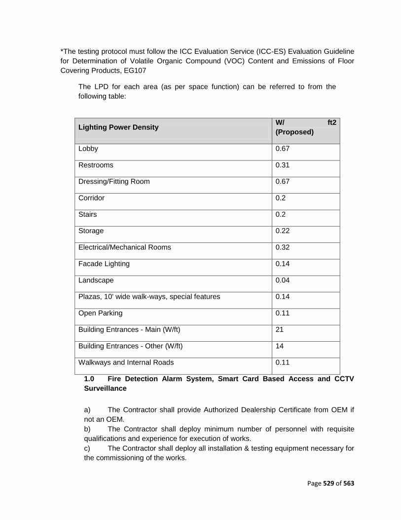
Page 529 of 563
*The testing protocol must follow the ICC Evaluation Service (ICC-ES) Evaluation Guideline
for Determination of Volatile Organic Compound (VOC) Content and Emissions of Floor
Covering Products, EG107
The LPD for each area (as per space function) can be referred to from the
following table:
Lighting Power Density
W/ ft2
(Proposed)
Lobby 0.67
Restrooms 0.31
Dressing/Fitting Room 0.67
Corridor 0.2
Stairs 0.2
Storage 0.22
Electrical/Mechanical Rooms 0.32
Facade Lighting 0.14
Landscape 0.04
Plazas, 10' wide walk-ways, special features 0.14
Open Parking 0.11
Building Entrances - Main (W/ft) 21
Building Entrances - Other (W/ft) 14
Walkways and Internal Roads 0.11
1.0 Fire Detection Alarm System, Smart Card Based Access and CCTV
Surveillance
a) The Contractor shall provide Authorized Dealership Certificate from OEM if
not an OEM.
b) The Contractor shall deploy minimum number of personnel with requisite
qualifications and experience for execution of works.
c) The Contractor shall deploy all installation & testing equipment necessary for
the commissioning of the works.

Page 530 of 563
d) The Contractor will carry-out any interfacing / Integration of the systems as
required between the systems and also with the BMS (Lift, AHU, Lighting, DG Set
Panels pumps, water tanks,) in future.
e) The Contractor shall train the designated purchaser‘s, Employer‘s staff for
operation of the system on-site, as necessary.
f) The required drawings of the building layouts with estimated requirements
will be provided as a reference (and are not limited for designing the systems).
g) Required UPS Power only will be made available by the purchaser. The
power cabling & Ethernet / Optical Fiber cabling, Ethernet Switches and other
network hardware shall be provided by the Contractor.
h) Any material (civil, electrical, communication / networking hardware) required
for installation work, site improvisation / retrofitting the systems in the buildings will
be arranged by the Contractor.
i) The Acceptance test requirements & the Test procedure / plan to be
submitted by the Contractor.
j) The Contractor shall obtain the required permits / permissions from the
related authorities / regulatory bodies as applicable before commencing the work.

Page 531 of 563
CHAPTER 9 MAINTANCE REQUIREMENTS
9.1 MAINTENANCE REQUIREMENTS
1.0 The Contractor shall, at all times maintain the Project Components in
accordance with the provisions of this Agreement, Applicable Laws and Applicable
Permits. The Contractor shall maintain the Project Works for a period of 3 (Three)
years commencing from the date of Of commissioning of al Works
1.1 During the Maintenance Period, the Employer shall provide to the Contractor
access to the Site for Maintenance in accordance with this Agreement. The
obligations of the Contractor hereunder shall include:
a) undertaking routine maintenance;
b) undertaking repairs to structures;
c) informing the Employer of any encroachments on the Project Site;
and
d) operation and maintenance of all utility service lines, communication,
patrolling, and administrative systems necessary for the efficient
maintenance of the Project Works in accordance with the provisions of this
Agreement.
1.2 The Contractor shall repair or rectify any Defect or deficiency set forth in
Paragraph 2 of this Schedule-E within the time limit specified therein and any failure
in this behalf shall constitute non-fulfillment of the Maintenance obligations by the
Contractor. Upon occurrence of any breach hereunder, the Employer shall be
entitled to effect reduction in monthly Operation and Maintenance payment, without
prejudice to the rights of the Employer under this Agreement, including Termination
thereof.
1.3 All materials and works for operations and maintenance of roads and
pavements shall conform to the Specifications for Road and Bridge Works (Fifth
Revision, April 2013), issued by the Ministry of Road Transport & Highways
(MoRT&H) and the relevant IRC publications.
1.4 All materials and works for operations and maintenance of Potable water
supply rising mains and distribution networks, Elevated Service Reservoirs (ESR),
Recycled water supply rising mains and distribution networks including valves, flow
meters etc. shall confirm to CPHEEO Manual on Operation and Maintenance of
water supply systems, 2005, MoUD, GOI
1.5 Where the Standards and Specifications for any of the above work are not
given, Good Industry Practice shall be adopted to the satisfaction of the Employer‘s

Page 532 of 563
Engineer.
9.2 REPAIR/RECTIFICATION OF DEFECTS AND DEFICIENCIES
The obligations of the Contractor in respect of Maintenance Requirements shall include
repair and rectification of the Defects and deficiencies specified in Appendix E-I of this
Schedule-E within the time limit set forth therein.
9.3 OTHER DEFECTS AND DEFICIENCIES
In respect of any Defect or deficiency not specified in Appendix E-I of this Schedule-E, the
Employer‘s Engineer may, in conformity with Good Industry Practice, specify the
permissible limit of deviation or deterioration with reference to the Standards and
Specifications, and any deviation or deterioration beyond the permissible limit shall be
repaired or rectified by the Contractor within the time limit specified by the Employer‘s
Engineer.
9.4 EXTENSION OF TIME LIMIT
Notwithstanding anything to the contrary specified in this Schedule-E, if the nature and
extent of any Defect or deficiency justifies more time for its repair or rectification than the
time specified), the Contractor shall be entitled to additional time in conformity with Good
Industry Practice. Such additional time shall be determined by the Employer‘s Engineer and
conveyed to the Contractor and the Employer with reasons thereof.
9.5 EMERGENCY REPAIRS/RESTORATION
Notwithstanding anything to the contrary contained in this Schedule-E, if any Defect,
deficiency or deterioration in the Project Components a hazard to safety or risk of damage
to property, the Contractor shall promptly take all reasonable measures for eliminating or
minimizing such danger.
9.6 DAILY INSPECTION BY THE CONTRACTOR
The Contractor shall, through its engineer, undertake a daily visual inspection of the Project
Components and maintain a record thereof in a register to be kept in such form and manner
as the Employer‘s Engineer may specify. Such record shall be kept in safe custody of the
Contractor and shall be open to inspection by the Employer and the Employer‘s Engineer at
any time during office hours.
9.7 REPAIRS ON ACCOUNT OF NATURAL CALAMITIES
All damages occurring to the Project Components on account of a Force Majeure Event or
default or neglect of the Employer shall be undertaken by the Employer at its own cost. The
Employer may instruct the Contractor to undertake the repairs at the rates agreed between
the Parties.

Page 533 of 563
9.8 LANDSCAPE AREAS
9.8.1 MAINTENANCE WORKS OF LANDSCAPED AREAS
1.1. General
i. The Contractor shall maintain the landscape for a 3 year period after the date
certified by the Employer that the work has been satisfactorily completed (issue of
Certificate of Completion).
ii. The extent of the landscape to be maintained by the Contractor shall be deemed to
cover and include all soft landscape areas within the overall project boundaries as
shown on the drawings including all existing soft landscape not affected by the
contract works and retained intact or nearly so through the end of the contract period
as well as all the landscape works covered in the contract scope of works. No
additional maintenance charges will be allowed unless specifically agreed to by the
Employer in writing.
iii. The Contractor shall ensure that a senior qualified supervisor is made available for
organising and running the maintenance programme. The Contractor shall also have
available an experience foreman who can supervise the workers on a day-to-day
basis. An adequate trained labour force of at least 3 workers must be available for
routine work and they must be on site for at least half a working day, 5 days per
week during the maintenance period. Additional grass cutting operators will be
needed to ensure adequate cutting and cleaning.
iv. The Contractor‘s Supervisor shall inspect the site once per week during the
maintenance period and shall prepare a brief schedule of operations required for the
coming week. The format for the schedule of operations will cover each distinct
areas of the site such as frontage, rear, courtyard, roof, interior, etc. The schedule
shall describe the operations the Contractor intends to carry out in the coming week
to cover the items listed in the specification and to ensure that the current weather
conditions and growing performances, insect attack, etc is taken into account.
v. A copy of this schedule is to be submitted to the Employer every week so that a
running record of proposed operations can be checked at the maintenance
inspections each month. If in the opinion of the Employers Landscape Architect the
maintenance works have not been satisfactorily carried out according to site
conditions and the specifications, part of the monthly payment will be withheld until
the works have been satisfactorily carried out.
vi. The contractor shall carry out all necessary measures to ensure that all pot plants,
trees and shrubs and other plants shall thrive and become established within this
period. All landscape areas will be inspected monthly and lists of remedial works
issued after each inspection. All items on the remedial lists are to be carried out by
the time of the next inspection, ie within one month.
vii. The Contractor shall keep the landscape areas clean and tidy at all times and
dispose of all waste materials arising from the cleaning.

Page 534 of 563
1.2. Maintenance of Planted Areas: Trees, Shrubs,
Climbers, Herbaceous and Ground Covers
i. The Contractor shall water all trees, palms, shrubs, ground cover, rooted shoots,
herbaceous plants and other planting areas as often as necessary to keep the
ground moist all around and to the full depth of the roots of the plants to a minimum
depth of saturation of:
- 100mm for groundcover
- 300mm for shrubs
- 750mm for trees
ii. Fresh water only shall be used for the Works. Water shall be supplied to the
Contractor from agreed points on the site. However, it will be only to necessary for
the Contractor to supply his own means of transport from the watering points to the
plant beds.
iii. An inspection of watering requirements is to be made by the Contractor at least two
times a week in dry weather.
iv. Water shall be supplied using an approved hose or sprinkler so as not to cause
compaction or wash-outs of the soil or loosening of plants. The Contractor shall
immediately make good any such damage, soil erosion or outwash and plants
loosened by erosion are to replanted or if damaged, replaced.
v. All plant beds are to be kept in a weed free condition with a weeding operation once
a month. All weeds, stones and rubbish collected from this operation shall be
removed from the site to a tip to be found by the Contractor. Herbicides may not be
used on this site unless a specific application in writing is made by the Contractor
with full back up data on the performance of the chemicals and the particular need
for the chemicals use. Approval will in all cases be subject to the Landscape
Architect‘s decision.
vi. After weeding, at least once per month the soil surface is to be lightly broken up
between plants using a pronged fork upto maximum depth of 100mm. Contractor
shall Take care not to disturb the root systems of plants. After forking the soil loose,
the mulch and loosened soil are to be raked to give an even re-distribution of the
mulching materials
vii. Firming up and adjusting of stakes/ties shall be carried out monthly to ensure that
the trees and shrubs are firmly held in the ground. If required guy ropes or tree pits
shall be adjusted, tightened or loosened. If tree ties or ropes are rubbing the bark of
the trees, the ties are to be taken off and retied. Any damaged branches are to be
carefully pruned and the wounds sealed.
viii. All protective fencing is to be maintained and kept in good condition and in position
until the end of the maintenance period.

Page 535 of 563
ix. Trees shall be pruned if dead, rotten or crossed branches are present or to maintain
a clear stem up to the specified height using the methods described below. Tree
pruning is to be reviewed monthly.
x. All shrubs and ground covers are to be reviewed monthly and pruned as and when
required during the Maintenance Period to promote bushy growth and good
flowering characteristics. The shrubs shall be checked and all dead wood, broken,
damaged or crossed branches shall be cut back, depending on species. Pruning and
removal of branches is to be carried out using sharp clean implements to give a
clean sloping cut with one flat face. Ragged edges of bark or wood are to be
trimmed with a sharp knife.
xi. Pruning for all plants shall be carried out as follows:
- Pruning is to be done with the cut just above and sloping away from an
outward facing health bud.
- Removal of branches is to be done by cutting flush with the adjoining stem
and in such a way that no part of the stem is damaged or torn.
- Ragged edges of bark are to be trimmed with a sharp knife.
- Any cuts or wounds over 25mm diameter are to be painted with an approved
sealant after trimmed.
- All pruning to be cleared up and removed from site after pruning.
xii. All hedges, mat forming herbaceous plants and ground cover plants shall be clipped
with shears as often as necessary (at least monthly) to maintain a tidy appearance.
Tall hedges are to be cut to forms shown on the drawings. Fertiliser is to be applied
to clipped areas around 1-2 weeks after clipping.
xiii. Selective pruning of flowering plants shall be done where special flowering
characteristics are required such as for Ixoras, Hibiscus, Allamanda where flowering
takes places on twig ends. Heavy clipping must not be used for these species since
this will remove future flower buds. Selective pruning by clipping non flowering twigs
and leaving flowering twigs is necessary for these plants, and this operation must be
done by experienced workers.
xiv. The Contractor shall allow for monthly fertiliser operations during the Maintenance
Period. An approved slow release fertiliser shall be applied to each plant at the rate
of 50gm per shrub and 200gm per tree, one month after planting and thereafter
monthly. After spreading the fertiliser around the base of the plant the granules shall
be lightly forked into the soil, and the plant well watered. Herbaceous and ground
cover areas shall receive 25mm of approved soil conditioner, evenly spread and
mixed with 50gm/m2 of approved slow release fertiliser, evenly spread over entire
area and lightly forked into the soil to break up the top layer, and the area well
watered on a month by month basis.

Page 536 of 563
xv. The horticultural requirements of different plants or areas may involve variations to
those techniques (such as the use of organic liquid fertilisers for sensitive plants)
and variations in method will be authorised as required.
xvi. Heavy feeding plants such as Canna, Heliconia and Lantana shall be dressed with a
25mm mulch of approved organic compost or similar approved compost every 2
months, lightly forked in around the base of the plants.
xvii. Additional mulching layer, 25mm deep to be spread and forked in over all planted
areas at 3 monthly intervals.
xviii. The Contractor shall make regular weekly checks to ensure that the plant material is
insect and pest and fungus free. No pesticides may be used unless approval from
the Landscape Architect is given from the Contractor stating the chemical intended
for use; concentration, spraying programme and including full technical details of the
product.
1.3. Maintenance of Lawn Areas
i. The Contractor shall mow all lawn areas using approved cutting equipment to
maintain a close sward to a height of not less than 20mm and not more than 30mm
for all grass types.
ii. Mowing shall be carried out generally weekly, except in dry weather and grass shall
not be allowed to flower between cuts.
iii. Weekly inspections are to be made to ensure adequate planning of grass cuts to suit
growth and weather conditions. All clippings to be gathered up and removed from
site.
iv. All grass areas are to be watered by means of sprinklers during dry weather as often
as is required to keep the grass green and the soil moist.
v. The Contractor shall provide hoses and sprinklers for use from water points
provided. Weekly inspections are to be made to determine the need for water and,
in dry weather watering must be done to moisten the soil to a depth of 100mm.
vi. Fertiliser of NPK value 10-15-15 or similar approved be spread at a rate of 40gm/sq
m over all grass areas at monthly intervals, using approved spreading equipment to
give an overall even spread. Grass areas that have been fertilised shall be watered if
no rain falls within 24 hours.
vii. The Contractor shall apply top-dressing of not more than 15mm depth fine sand and
granulated compost raked and spread evenly over the lawn areas. The next top-
dressing shall be applied only after the grass has grown through to a mowable
height.
viii. There shall be at least two applications of topdressing during the maintenance
period, to be directed by the Landscape Architect appointed by Contractor.

Page 537 of 563
ix. If depressions or bumps over 25mm deep or high in turf areas during the
maintenance period these are to be levelled out by lifting the turf and raising the soil
level with sand/compost mix or trimming to level grades, followed by re-turfing.
x. Grass areas are to be kept free of weeds, annual grasses, fungus and insect attack
and free of stones or other debris throughout the maintenance period as often as is
required.
xi. All chemicals used shall be to the approval of the Employer/Employer‘s
representative. Assessment of these operations is to be prepared on the basis of
the weekly maintenance inspection chart.
xii. If compaction or consolidation takes place or hard passing or baking of the soil
occurs, the soil areas are to be well watered first and lightly loosened by mechanical
means such as spiking, slitting or hollow tinning using equipment approved by the
Employer/Employer‘s representative.
1.4. Replacement Planting
i. If during the course of the Maintenance Period trees or shrubs or other plants die
because of a fault by the Contractor, the Contractor shall replace the plant at no cost
to the Employer.
ii. All questions related to responsibility for the replacement planting will be subject to
site inspection and agreement of the appointment of responsibility.
iii. This will be done very month at the monthly maintenance inspections.
1.5. Final Handover
i. Two weeks before the end of the Maintenance Period a joint inspection shall be held
with the Maintenance Agency, Contractor and the Employer/Employer‘s
representative review the requirements for alteration or replacement in order to gain
approval for Final Handover.
ii. In order to ensure satisfactory handover procedures, the site meetings held each
month between the Contractor and Employer/Employer‘s Representative will be
used to inspect and approve the maintenance works which will be reviewed to
ensure adequate work has been done.
iii. At the time of the final inspection, all areas under this contract shall be free of
weeds, neatly cultivated and raked, and all plant boxes in good order.
iv. Grass shall be neatly cut and all clippings removed. No bare patches of earth shall
be visible in turf or planting areas unless specified (that is rings around tree trunks).
v. If, after this inspection, the Employer/Employer‘s representative is of the opinion that
all work has been performed in accordance with the drawings and specifications, the
Employer/Employer‘s representative will give written letter of acceptance and
completion of the project.

Page 538 of 563
vi. If, all or certain portions of the work are not acceptable under the terms and intent of
the drawings and specifications, the formal maintenance period for all the work shall
be extended at no cost to the Employer/Employer‘s representative until the defects
in the work have been corrected and the work is accepted by the
Employer/Employer‘s representative.
Space for storing all equipments and other materials to be finalized as
directed by the owner.
Site inspection by the chief horticulturist with owner/owner's representative
shall be made every week to analyze the health of the plants and for improvements
it is mandatory for contractor to remain present at site during such visits.
All maintenance charges to be consolidated towards all types of services
mentioned below including the supply of required numbers of trained malis,
materials, manures and fertilizers, pesticides and fungicides, lawn mowers and other
required machineries and tools, etc, all complete.
Annual Maintenance of Irrigation System, Water Features Including Filtration System
Contractor shall perform following activities while maintaining the system,
Routine cleaning of the water features
Vacuum suction of sediments on the floor / wall cleaning
Grubbing of hard settlement / salts Periodically
Skimming to remove moulds / scale formation
Removal of floating debris by nets
Operation of the filtration system for filtration & daily back wash
Addition of consumables such as chlorine & acids, etc
9.9 ELECTRICAL WORKS:
9.9.1 SCOPE
The scope of Contractor includes O&M for 05 years and Training of Employer‘s staff for
operation and handling of the respective systems, carry out Operation & Maintenance of
Electrical Distribution Network, system along with its associated components including the
following;
i) 33kV RMU Panel
ii) Compact Substation
iii) Distribution Transformer
iv) DG Set
v) Elevator / Escalator
vi) 415 V Switchboards

Page 539 of 563
vii) HV & LV Cable network, Busduct
viii) Earthing & Lightning protection System
ix) Lighting System with wiring
x) Comprehensive Maintenance of all the Systems installed.
9.9.2 WORK DESCRIPTION
CONTRACTOR shall carry out the following maintenance activities
a. Contractor should carry out Operation and Maintenance requirements as per
O&M manual of each equipment, CPWD norms and as per DISCOM Company.
b. Carry out Preventive & Predictive maintenance of the equipment and
associated system to ensure the health of the network.
c. Carry out breakdown maintenance of equipment and systems including
identifying the fault and its location; repairs with all required spares and tools; testing
and regularize the operations with minimum downtime.
d. Maintain the Critical Spares required for emergency resolution of outages of
Key equipments and systems.
e. Carry out Root Cause Analysis to find the reasons and taking measures to
eliminate its reoccurrence.
f. Provide required all the necessary latest Tools and Tackles along with Test
Equipments for carrying maintenance activities
g. Necessary Human Safety Norms as per the updated Indian Electricity Rules.
9.9.3 REPAIR / RECTIFICATION OF DEFECTS AND DEFICIENCIES
i) Complaints
The Contractor shall receive calls for any and all problems experienced in the
operation of the system under this contract, attend to these within 2 hours of receiving
the complaints and shall take steps to immediately correct any deficiencies that may
exist. Corrective actions to problem experienced, if takes longer time, shall be
complied 100% by during next business hours.
ii) Repairs
All equipment that require repairing shall be immediately serviced and repaired as
defined below. Since the period of Maintenance runs concurrently with the defects
liability period, all replacement parts and labour shall be supplied promptly free-of-
charge to the Owner.

Page 540 of 563
a) Minor rectifications - 2 to 4 hours
b) Major rectifications - 12 to 24 hours
iii) Extension of time limit
Notwithstanding anything to the contrary as specified above, if the nature and extent
of any Defect or deficiency justifies more time for its repair or rectification than the
time specified herein, the Contractor shall be entitled to additional time in conformity
with Good Industry Practice. Such additional time shall be determined by the Owner‘s
Engineer and conveyed to the Contractor and the Owner with reasons thereof.
iv) Emergency Repairs/Restoration
Notwithstanding anything as mentioned above, if any defect, deficiency or
deterioration in the Project Components poses a hazard to safety or risk of damage
to property, the Contractor shall promptly take all reasonable measures for
eliminating such danger.
9.9.4 UPTIME GUARANTEE
The Contractor shall provide log in the form of diskettes and bound printed
comprehensive log book containing tables for daily record of all temperatures,
pressures, humidity, and power consumption, starting and stopping times for various
equipment, daily services rendered for the system alarms, maintenance and record of
unusual observations etc. Contractor shall also submit preventive maintenance
schedule.
Each tenderer shall submit along with the tender, a detailed operation assistance
proposal for the Engineer In-charges/Consultant‘s review. This shall include the type of
service planned to be offered during Defects Liability Period and beyond. The
operation assistance proposal shall give the details of the proposed monthly reports to
the Management.
The tenderer shall include a list of other projects where such an Operation Assistance
has been provided.
9.9.5 OPERATION AND MAINTENANCE
i) Operation contract (Electrical System)
a. 10 hours a day, year round during working office hours for full load
b. 14 hours a day, year round during non-work hours for part load.
c. All stand-by equipment to be operated as per mutually agreed programme.

Page 541 of 563
d. Proper entry and upkeep of relevant log books.
e. Maintain complaints register. Submit weekly report.
f. Proper housekeeping of all areas under the contract.
g. Prepare daily consumption report and summary of operation.
ii) All Inclusive Maintenance Contract
a. Scope.
The AMC shall cover all the items installed by the contractor including replacement of
all switches, fittings etc. consumable like bulbs, tubes, oil etc. shall be excluded.
b. Routine Preventive Maintenance Schedule to be submitted
i. Schedule to cover manufacturer‘s recommendation and/or common
engineering practice (for all plant and machinery under contract).
ii. Plant and machinery history card giving full details of equipment and frequency
of checks and overhaul.
iii. Monthly status report.
iv. Entire Electrical installation to be repainted in fourth year (from commissioning)
before the expiry of operation and maintenance contract.
c. Uptime during maintenance contract
i. 99.9% uptime of all systems under contract.
ii. Up time shall be assessed every month and in case of shortfall during any
month the contract shall be extended by a month.
iii. There shall be no reimbursement for the extended period.
iv. Break-downs shall be attended to within ten hours of reporting.
d. Manpower
i. Adequate number of persons to the satisfaction of the Engineer In-charge shall
be provided including relievers.
ii. Statutory requirements of EPF, ESIC and other applicable labour legislations to
be complied with; and monthly certification to that effect to be submitted.

Page 542 of 563
iii. Duty allocation and Roaster control shall be contractor‘s responsibility.
iv. No overtime shall be payable by Owner for any reason whatsoever.
e. Shut Downs
i. Routine shut downs shall be permitted only as allowed by the Chief Engineer.
ii. Contractor shall be at liberty to carry out routine maintenance as and when
required but with prior permission of the Owner.
9.10 VENTITATION
a) The Contractor shall, at all times maintain the Project Components for
Bhopal Government Housing Tender for Plot 22 & 23 in accordance with the
provisions of this Agreement, Applicable Laws and Applicable Permits.
b) The Contractor shall, through its engineer, undertake a daily visual
inspection & duct clearance on camera lenses, detectors of the Project Components.
c) Any damage breakage of any apparatus, equipment, sensors and system in
general should not remain non-functional for more than two hour.
d) Essential maintenance spares to be available for immediate repair.
e) Any damage to fan/damper/VCD/grilles/louvers shall be replaced or rectified
within 2 hours.
f) Any breakage to power cables shall be replaced or rectified within 2 hours.
g) The min. maintenance spare of ventilation fans has to be considered by
contractor without any additional cost.
h) CONTRACTOR shall replace/repair burnout motor/ damage actuator/
damage fan blade within 48hours.
i) CONTRACTOR should check physical and working condition of fans once in 3
months and should take necessary actions, if finds any defects in the same.
j) CONTRACTOR should conduct dry run test of all lift well pressurization fans for 15
mins once in a six months. CONTRACTOR should specifically check these fans are
automatically get operated based on signal received from fire panel.
k) CONTRACTOR should coordinate with instrumentation person to conduct
the same.
9.11 REPAIR / RECTIFICATION OF DEFECTS AND DEFICIENCIES
a) Architectural, Civil maintenance
1.1 Any break down of door / window / hatch accessories should be replaced /
rectified within 24 hours.
1.2 Any breakage of flooring, false ceiling and peeling of paint should be rectified
in 48 hours.

Page 543 of 563
1.3 Any damage to External stone cladding, flooring, paving, hardscape, façade
etc. shall be rectified within 48 hours.
1.4 Any crack / peeling of Plaster shall be repaired within 48 hrs
1.5 Any water leak in building shall be stopped with 2 hrs and suitable
rectification process undertaken.
1.6 Housekeeping services for common utility areas for SPV, BEC building and
connecting street / corridor.
b) Landscape
2.1 Any non-surviving/ unhealthy saplings should be replaced within 48 hours.
2.2 Trees uprooted / damaged should be removed within 8 hours and replaced in
one week time.
2.3 Blockages/ leakages / damages in Irrigation System, Water Features
Including Filtration System should be made good in 24 hours.
2.4 Any Hardscape / signage damage shall be repaired within 24 hrs.
c) Electrical
1.0 Any Electrical equipment / Apparatus/ cables, etc. shall be restored within
two hours in case of minor faults and within eight hours in case of major faults.
1.1 Faulty lighting fixtures should be rectified within six hours.
1.2 Essential spares to be available for immediate repairs.
d) HVAC
2.1 The Contractor shall, at all times maintain the Project Components in
accordance with the provisions of this Agreement, Applicable Laws and Applicable
Permits.
2.2 The Contractor shall, through its engineer, undertake a daily visual
inspection & duct clearance on camera lenses, detectors of the Project
Components.
2.3 Any damage breakage of any apparatus, equipment, sensors and system in
general should not remain non functional for more than two hour.
2.4 Essential maintenance spares to be available for immediate repair.

Page 544 of 563
2.5 Any damage to fan/damper/VCD/grilles/louvers shall be replaced or rectified
within 2 hours.
2.6 Any breakage to power cables shall be replaced or rectified within 2 hours.
2.7 The min. maintenance spare of ventilation fans has to be considered by
contractor without any additional cost.
2.8 CONTRACTOR shall replace/repair burnout motor/ damage actuator/
damage fan blade within 48hours.
2.9 CONTRACTOR should check physical and working condition of fans once in
3 months and should take necessary actions, if finds any defects in the same.
2.10 CONTRACTOR should conduct dry run test of all lift well pressurization fans
for 15 mins once in a six months. CONTRACTOR should specifically check these
fans are automatically get operated based on signal received from fire panel.
CONTRACTOR should coordinate with instrumentation person to conduct the same.
e) Fire detection , alarm system ,access control and surveillance
2.1 Any damage breakage of any apparatus, equipment, sensors and system in
general should not remain nonfunctional for more than two hour.
2.2 Essential spares to be available for immediate repair.
f) Roads and Parking Areas
Nature of Defect or Deficiency Time Limit For
Repair/Rectification
(a) Carriageway and Paved Areas
(i) Any cracks in road surface 15 (fifteen) days
(ii) Any depressions, rutting exceeding 10 mm
in road surface 30 (thirty) days
(iii) Bleeding/skidding 7 (seven) days
(iv) Any other defect/distress on the road 15 (fifteen) days
(v) Damage to pavement edges 15 (fifteen) days
(iv) Removal of debris, dead animals 6 hours
(b) Earthen Shoulders, Side Slopes, Drains and Culverts
(i) Variation by more than 1 % in the
prescribed slope of camber/cross fall (shall 7 (seven) days

Page 545 of 563
Nature of Defect or Deficiency Time Limit For
Repair/Rectification
not be less than the camber on the main
carriageway)
(ii) Edge drop at shoulders exceeding 40 mm 7 (seven) days
(iii) Variation by more than 15% in the
prescribed side (embankment) slopes
30 (thirty) days
(iv) Rain cuts/gullies in slope 7 (seven) days
(v) Damage to or silting of culverts and side
drains
7 (seven) days
(vi) De-silting of drains 24 hours
(vii) Railing, parapets, crash barriers 7 (seven) days (Restore
immediately if causing safety
hazard)
(c) Road Lighting
(i) Any major failure of the system 24 hours
(ii) Faults and minor failures 8 hours
(d) Trees and Plantation
(i) Obstruction in a minimum head-room of 5 m
above carriageway or obstruction in visibility
of road signs
24 hours
(ii) Removal of fallen trees from carriageway 4 hours
(iii) Deterioration in health of trees and bushes Timely watering and treatment
(iv) Trees and bushes requiring replacement 30 (thirty) days
(v) Removal of vegetation affecting sight line
and road structures
15 (fifteen) days
(e) Other Project Facilities and Approach Roads
(i) Damage in approach roads and pedestrian
facilities
15 (fifteen) days

Page 546 of 563

Page 547 of 563
CHAPTER 10 APPLICABLE PERMITS
a) License from inspector of factories or other competent Authority for setting up
batching plant;
b) Clearance of Pollution Control Board for setting up batching plant;
c) Any other permits, clearances or approvals required under Applicable Laws.
Applicable permits, as required, relating to environmental protection and conservation shall
have been procured by the EMPLOYER in accordance with the provisions of this
Agreement.
10.1 ARCHITECTURE
Commencement Certificate, Intermediate Certificates, Occupancy Certificate
and Completion Certificate from local municipal body or designated authority
for the buildings.
Town Planning Department remarks for applicable norms / zones / uses.
10.2 CIVIL & STRUCTURES
Forest department Clearance for clearing of site of trees and shrubs if
required.
Water Connection from Public Health Engineering Department (State).
Provision and permit for connection to proposed municipal sewage collection
system at directed location from local municipal body.
Project Clearance from General Inspectorate for Emergency Situations.
Project Clearance from the Solid Waste Management Authority.
10.3 ELECTRICAL
The Contractor shall obtain, as required under the Applicable Laws, the following Applicable
Permits:
(a) Liasoning and approval from State Electricity Board / DISCOM to complete
the work.
(b) Any other permits, clearances or approvals required under Applicable Laws.
(c) It shall be the Contractor‘s responsibility to arrange for inspection of
elevators/escalators by the inspector or local authority. However, the actual
deposited fees, if any for the inspection shall be borne by the contractor. The
Contractor shall also be responsible for follow up action and obtain and deliver to the
Owner/Employer the license/ permit required under the local/ provincial / national
regulations/bye-laws free of cost. Nothing extra whatsoever on this account shall be
paid to the contractor.

Page 548 of 563
(d) License:- It is mandatory to obtain the licenses to install, operate and
maintain the lifts from Lift Inspector (P.W.D.) Government of Madhya Pradesh, by
paying necessary government charges. The rates quoted shall be inclusive of this.
10.4 FIRE FIGHTING
Preliminary approval from Chief Fire Officer prior to construction and final
approval on completion of project.
10.4.1 FDA ACCESS CONTROL & SECURITY
Fire Detection & Alarm System - Compliance with IS:2189:1988, BIS: 15908
standards and certification from the Regional Fire Officer / Chief Fire Officer.
If any hazardous waste is generated from the facility like used DG oil, used
batteries etc., the same should be handed over to only SPCB approved
agencies for handling hazardous waste.

Page 549 of 563
CHAPTER 11 TESTS ON COMPLETION
11.1 CIVIL & STRUCTURAL
Joints Inspection
Water Proofing Test for sunken slabs of utility room, toilets, etc., drive way
and parking slab, roof slabs, water tank walls, retaining wall.
Non-destructive Testing of Building Envelope Systems Using Infrared
Thermography
Hydrostatic checks for UGTs, OHTs , and all water retaining structures as
per IS 3370.
11.2 ELECTRICAL
11.2.1 COMPLETION AND POST COMPLETION ACTIVITIES
Mechanical completion is said to occur, when all erection/installation and commissioning of
all electrical works and minor civil works under the scope of the Contractor are completed to
the satisfaction of the Client‘s Representative with,
a) All installation alignment checks.
b) All panels and equipment erected, grouted, with all cabling and wiring, terminations,
routing, clamping, dressing, tagging, ferruling duly completed including continuity and
megger testing, and all installation checks.
At the stage of Mechanical completion, the Contractor shall ensure that all physical,
aesthetic and workmanship aspects are totally completed, and the plant is fit and sound for
undertaking pre-commissioning checks followed by commissioning.
Upon achieving mechanical completion, the Contractor shall notify the Client of such
mechanical completion upon which the Client shall proceed with the checking of the works.
The Client may inform the Contractor regarding deficiencies for rectification by the
Contractor within a jointly agreed period before the pre-commissioning checks could be
undertaken. Alternately the Client, when the defects are of minor nature may undertake the
pre-commissioning checks, permitting the Contractor to concurrently undertake rectification
of such defects. Rectification of all defects, so notified by the Client, to his satisfaction shall
be a prerequisite to issue of Taking Over Certificate.
11.2.2 TESTING AND COMMISSIONING
The Contractor shall carry out commissioning tests in the presence of the Client‘s
representative. The evaluation of test results and decision passed by the Client‘s
representative regarding the test results will be final and binding on the Contractor. Any
additional tests or repetition of tests to establish satisfactory operation of any equipment

Page 550 of 563
shall be carried out by the Contractor, if so desired by the Client‘s representative at no extra
cost.
The completion checks and commissioning tests to be carried out shall include, but not be
limited to, those described in subsequent paragraphs, as applicable to the individual
equipment/system.
All checks and tests shall be as per the Manufacturer‘s drawing manuals, relevant codes of
installation and commissioning checklists described in subsequent paragraphs.
Among other commissioning tests, the following shall be carried out at site after completion
of installation. Contractor shall ensure to use calibrated test equipment having valid
calibration test certificates from standard laboratories traceable to National Standards /
International Standards. All tests to be carried out in the presence of Client‘s
representatives.
a) Switchboard: Power frequency high voltage test, IR test, operation tests
b) Relays: Check internal wiring, relay settings
c) Cables
All new LT cables shall be megger tested before terminating / jointing. After
terminations / joints shall be megger tested by 1000V megger.
All HT cables shall be megger tested before terminating / jointing. After
terminations / joints shall be megger tested by 5000V megger.
Cable core shall be tested for
- Continuity
- Absence of cross phasing
- Insulation resistance to earth
- Insulation resistance between conductors
d) Earthing System
Continuity of all conductors and joints. The Client‘s representatives may ask for earth
continuity tests, earth resistance measurements and other tests, which in his opinion are
necessary, to prove that the system is in accordance with design, specification, code of
practice and CEA Regulations 2010. Earth resistance value should be not greater than one
(1) ohm.
e) Lighting System
Commissioning tests stipulated in applicable standards and code of practice covering all
lighting system equipment
The Contractor shall carry out insulation resistance tests by a megger of following rating

Page 551 of 563
Control circuits up to 220 V 500 V megger
Power circuits up to 1.1 kV 1000 V megger
In general, the following checks shall be carried out on all the equipment/systems, as
applicable.
a) Name plate details according to approved drawings/ specifications
b) Any physical damage or defect and cleanliness
c) Tightness of all bolts, clamps and connections
d) Oil leakages and oil level
e) Condition of accessories and their completeness
f) Clearances
g) Earthing connections
h) Correctness of installation with respect to approved drawings/specifications
i) Lubrication of moving parts
j) Alignment
k) Correctness and condition of connections
11.2.3 COMMISSIONING TESTS
The following commissioning tests are to be carried out on all the equipment/systems, as
applicable and as desired by EMPLOYER/ STATUTORY requirements.
a) Insulation resistance measurement of equipment, accessories, cabling/wiring etc.
b) Dielectric tests on equipment, accessories, cabling/ wires etc.
c) Phase sequence and polarity
d) Voltage and current ratios
e) Vector group
f) Resistance measurement of winding, contacts etc.
g) Continuity tests
h) Calibration of indicators, meters, relays, etc.
i) Control and interlock checks
j) Settings of equipment and accessories
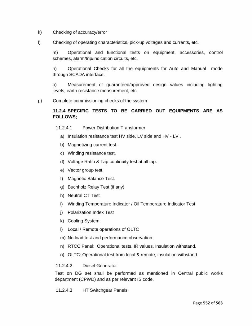
Page 552 of 563
k) Checking of accuracy/error
l) Checking of operating characteristics, pick-up voltages and currents, etc.
m) Operational and functional tests on equipment, accessories, control
schemes, alarm/trip/indication circuits, etc.
n) Operational Checks for all the equipments for Auto and Manual mode
through SCADA interface.
o) Measurement of guaranteed/approved design values including lighting
levels, earth resistance measurement, etc.
p) Complete commissioning checks of the system
11.2.4 SPECIFIC TESTS TO BE CARRIED OUT EQUIPMENTS ARE AS
FOLLOWS;
11.2.4.1 Power Distribution Transformer
a) Insulation resistance test HV side, LV side and HV - LV .
b) Magnetizing current test.
c) Winding resistance test.
d) Voltage Ratio & Tap continuity test at all tap.
e) Vector group test.
f) Magnetic Balance Test.
g) Buchholz Relay Test (if any)
h) Neutral CT Test
i) Winding Temperature Indicator / Oil Temperature Indicator Test
j) Polarization Index Test
k) Cooling System.
l) Local / Remote operations of OLTC
m) No load test and performance observation
n) RTCC Panel: Operational tests, IR values, Insulation withstand.
o) OLTC: Operational test from local & remote, insulation withstand
11.2.4.2 Diesel Generator
Test on DG set shall be performed as mentioned in Central public works
department (CPWD) and as per relevant IS code.
11.2.4.3 HT Switchgear Panels

Page 553 of 563
a) Check of electrical wiring.
b) Tests on auxiliary and control circuits.
c) Check of electrical operation of safety (interlocking, automatic changeover,
Local / Remote operations in test as well as service position including all
electrical interlocks etc).
d) Check of mechanical operations (insertion and withdrawal of removable
parts, locks and interlocks system, operation of safety shutters, Anti pumping
device operation etc.).
e) Protection system operation stability and sensitivity by primary injection
testing method including testing of metering circuits
f) Check of setting of all protective and measurement devices (e.g. protection
relays, smart devices, etc...).
g) IR values of power and control circuits
h) Panel indication, annunciation, space heater circuits
i) Spare contact for customer use
11.2.4.4 Control Circuit
a) Operational test of control circuits to be tested as per schematic drawing.
b) Indications/Alarm/Annunciation circuit to be tested as per control schematic
drawing.
c) Check for panel space heater and illumination circuits.
11.2.4.5 LT Switchgear Panels
a) Check of electrical wiring.
b) IR Values of power circuits & control circuits
c) Tests on auxiliary and control circuits.
d) Check of electrical operation of safety (interlocking, automatic changeover,
Remote closing / Tripping circuits etc…).
e) Check of mechanical operations (insertion and withdrawal of removable
parts, locks and interlocks system, operation of safety shutters, charging -
closing - tripping of breaker etc..).
f) Check of setting of all protective and measurement devices (e.g. protection
relays, smart devices, Secondary injection testing of protective relays/releases,
Trip circuit healthiness and tripping through relays/ release etc...).
g) Indication / Annunciation / Panel space heater circuit / Space contacts for
customer use
h) CT testing for polarity, ratio, IR values and magnetization for class PS
characteristics

Page 554 of 563
i) PT testing for ratio, IR values
j) Testing of modules for DOL/ Star-Delta/ATS/ Soft Starter starting or any
other starting method as per the schematic drawings applicable.
11.2.4.6 HV & LV power cable, control cable & cable accessories
a) IR Values before Hipot
b) Hi Pot test for MV & HV cables.
c) IR Values after Hipot
11.2.4.7 Induction Motor
a) Measurement of insulation resistance on motor windings, built-in
RTDs, anti-condensation heaters and bearing insulation, if any.
b) Tests on auxiliary and control circuits-Interlocks and simulation tests Auto/
Manual and local / remote operations
c) Bump start to check direction of rotation to match with driven equipment.
Bump start shall be performed with motors uncoupled to prevent damage to
equipment by reverse operation.
11.2.4.8 Earthing System
a) Earthing resistance of each electrode
b) Earth continuity check.
c) Overall resistance of earthing installation.
11.2.4.9 Lighting system
a) Check of electrical wiring.
b) Functional tests.
c) Lux level measurement for each plant area.
11.2.4.10 Elevator / Escalator
Test on Elevator shall be performed as mentioned in Central public works
department (CPWD) and as per relevant IS code.

Page 555 of 563
SECTION – 8
DRAWINGS
(ATTACHED SEPARATELY)
SECTION – 9
BILL OF QUANTITIES
( ATTACHED IN THE FINANCIAL BID SHEET)

Page 556 of 563
SECTION-10
ENVIRONMENT
HEALTH AND SAFETY REQUIREMENTS
(EHS POLICY)

Page 557 of 563
ENVIRONMENT, HEALTH & SAFETY POLICY
SPECIFICATION FOR ENVIRONMENT, HEALTH & SAFETY POLICY (EHS)
MANAGEMENT
CONTENTS
CLAUSE
NO.
TITLE
1.0 SCOPE
2.0 REFERENCES
3.0 REQUIREMENT OF ENVIRONMENT, HEALTH & SAFETY
3.1 MANAGEMENT RESPONSIBILITY
3.2 HOUSE KEEPING
3.3 ENVIRONMENT ,HEALTH & SAFETY
4.0 DETAILS OF EHS MANAGEMENT SYSTEM BY CONTRACTOR
4.1 ON AWARD OF CONTRACT
4.2 DURING JOB EXECUTION
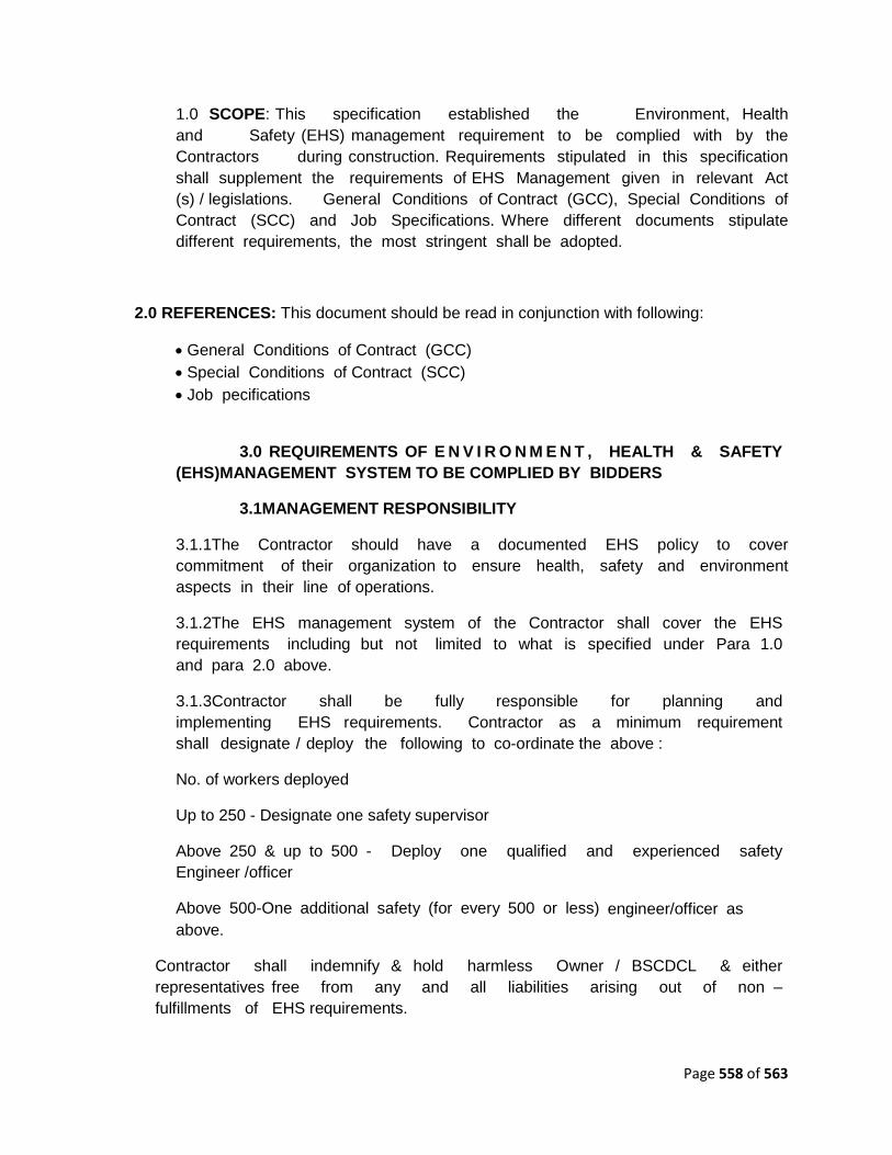
Page 558 of 563
1.0 SCOPE: This specification established the Environment, Health
and Safety (EHS) management requirement to be complied with by the
Contractors during construction. Requirements stipulated in this specification
shall supplement the requirements of EHS Management given in relevant Act
(s) / legislations. General Conditions of Contract (GCC), Special Conditions of
Contract (SCC) and Job Specifications. Where different documents stipulate
different requirements, the most stringent shall be adopted.
2.0 REFERENCES: This document should be read in conjunction with following:
General Conditions of Contract (GCC)
Special Conditions of Contract (SCC)
Job pecifications
3.0 REQUIREMENTS OF E N V I R O N M E N T , HEALTH & SAFETY
(EHS)MANAGEMENT SYSTEM TO BE COMPLIED BY BIDDERS
3.1MANAGEMENT RESPONSIBILITY
3.1.1The Contractor should have a documented EHS policy to cover
commitment of their organization to ensure health, safety and environment
aspects in their line of operations.
3.1.2The EHS management system of the Contractor shall cover the EHS
requirements including but not limited to what is specified under Para 1.0
and para 2.0 above.
3.1.3Contractor shall be fully responsible for planning and
implementing EHS requirements. Contractor as a minimum requirement
shall designate / deploy the following to co-ordinate the above :
No. of workers deployed
Up to 250 - Designate one safety supervisor
Above 250 & up to 500 - Deploy one qualified and experienced safety
Engineer /officer
Above 500-One additional safety (for every 500 or less) engineer/officer as
above.
Contractor shall indemnify & hold harmless Owner / BSCDCL & either
representatives free from any and all liabilities arising out of non –
fulfillments of EHS requirements.

Page 559 of 563
3.1.4 The Contractor shall ensure that the Environment, Health & Safety
(EHS) requirements are clearly understood & faithfully implemented at all levels at
site.
3.1.5 The Contractor shall promote and develop consciousness for Safety
, Health and Environment among all personnel working for the Contractor. Regular
awareness, program site meetings shall be arranged on EHS activities to
cover hazards involved in various operations during construction.
3.1.6 Arrange suitable first aid measures such as First Aid Box, trained
personnel to give First Aid, Stand by Ambulance or Vehicle and install fire
protection measures such as : adequate number of steel buckets with sand and
adequate fire extinguishers to the satisfaction of BSCDCL/Owner.
3.1.7 The Contractor shall evolve a comprehensive planned and
documented system for implementation and monitoring of the EHS requirements.
This shall be submitted to BSCDCL/Owner for approval. The monitoring for
implementation shall be done by regular inspections and compliance to the
observations thereof. The Contractor shall get similar EHS requirements
implemented at his sub-contractor(s) work site/office. However, compliance of
EHS requirements shall be the sole responsibility of the Contractor. Any review /
approval by BSCDCL/Owner shall not absolve contractor of his responsibility
/ liability in relation to all HSE requirements.
3.1.8Non-Conformance on EHS by Contractor (including his Sub-
contractors) as brought out during review/audit by BSCDCL/Owner
representatives shall be resolved forthwith by Contractor. Compliance report shall be
provided to BSCDCL/Owner.
3.1.9The Contractor shall ensure participation of his Resident
Engineer / Site-in- Charge in the Safety Committee / EHS Committees meetings
arranged by BSCDCL/Owner. The compliance of any observations shall be
arranged urgently. He shall assist BSCDCL/Owner to achieve the targets set by
them on EHS during the project implementation.
3.1.10 The Contractor shall adhere consistently to all provisions of EHS
requirements. In case of non-compliance or continuous failure in implementation
of any of EHS provisions; BSCDCL/Owner may impose stoppage of work
without any Cost & Time implication to Owner and/or impose a suitable penalty
for non-compliance with a notice of suitable period, up to a cumulative limit of
1.0% (one percent) of Contract Value with a maximum limit of Rs. 10 lakhs.
This penalty shall be in addition to all other penalties specified else where in the
contract. The decision of imposing stoppage work, its extent & monitory
penalty shall rest with BSCDCL/Owner & binding on the Contractor.
3.1.11 All fatal accidents and other personnel accidents shall be investigated by

Page 560 of 563
a team of Contractor‟s senior personnel for root cause & recommend
corrective and preventive actions. Findings shall be documented and suitable
actions taken to avoid recurrences shall be communicated to BSCDCL/Owner.
Owner / BSCDCL shall have the liberty to independently investigate such
occurrences and Contractor shall extend all necessary help and co-operation in
this regard.
3.2 HOUSE KEEPING
3.2.1Contractor shall ensure that a high degree of house keeping is
maintained and shall ensure inter alia the followings wherever applicable:
a. All surplus earth and debris are removed/disposed off
from the working areas to identified location(s).
b. Unused/Surplus Cables, Steel items and steel scrap lying
scattered at different places within the working areas are removed to identified
location(s).
c All wooden scrap, empty wooden cable drums and other combustible packing
materials, shall be removed from work place to identified location(s).
d. Roads shall be kept clear and materials like: pipes,
steel, sand boulders, concrete, chips and bricks etc. shall not be allowed on the
roads to obstruct free movement of men & machineries.
e. Fabricated steel structural, pipes & piping materials shall
be stacked properly for erection.
f.Water logging on roads shall not be allowed.
g. No parking of trucks / trolleys, cranes and trailers etc.
shall be allowed on roads which may obstruct the traffic movement.
h. Utmost care shall be taken to ensure over all cleanliness
and proper upkeep of the working areas.
i. Trucks carrying sand, earth and pulverised materials etc. shall
be covered while moving within the premises.
j. Only properly designed steel scaffolding materials to be used for
working at heights more than 3.0M . Double scaffolding using wooden ballis may be
allowed for working at height less than 3.0M
3.3 ENVIRONMENT, HEALTH AND SAFETY
3.3.1 The Contractor shall provide safe means of access to any
working place including provisions of suitable and sufficient scaffolding at various
stages during all operations of the work for the safety of his workmen, and,

Page 561 of 563
BSCDCL/Owner. Contractor shall ensure deployment of appropriate equipment and
appliances for adequate safety and health of the workmen and protection of
surrounding areas.
3.3.2 The Contractor shall ensure that all their staff and workers
including their sub-contractor(s) shall wear Safety Helmet and Safety shoes.
Contractor shall also ensure use of safety belt, protective goggles, gloves etc.
by the personnel as per job requirements. All these gadgets shall conform to relevant
IS specifications or equivalent.
3.3.3 Contractor shall ensure that a proper Safety Net System shall
be used at appropriate locations. The safety net shall be located not more than 30
feet (9.0 metres) below the working surface at site to arrest or to reduce the
consequences of a possible fall of persons working at different heights.
3.3.4 Contractor shall ensure that flash back arrester shall be used while
using
Gas Cylinders at site. Cylinders shall be mounted on trolleys.
3.3.5 The Contractor shall assign to his workmen, tasks
commensurate with their qualification, experience and state of health for driving
of vehicles, handling and erection of materials and equipments. All lifting
equipments shall be tested certified for its capacity before use. Adequate and
suitable lighting at every work place and approach there to, shall be provided by
the Contractor before starting the actual operations at night.
3.3.6 Hazardous and/or toxic materials such as solvent coating, or
thinners shall be stored in appropriate containers.
3.3.7 All hazardous materials shall be labelled with the name of
the materials, the hazards associated with its use and necessary precautions to be
taken.
3.3.8 Contractor shall ensure that during the performance of
the work, all hazards to be health of personnel, have been identified,
assessed and eliminated.
3.3.9 Chemical spills shall be contained & cleaned up immediately
to prevent further contamination.
3.3.10All personnel exposed to physical agents such as
ionizing radiation, ultraviolet rays or similar other physical agents shall be
provided with adequate shielding or protection commensurate with the type of
exposure involved.
3.3.11 Where contact or exposure of hazardous materials could
exceed limits or could otherwise have harmful affects, appropriate personal

Page 562 of 563
protective equipments such as gloves, goggles, aprons, chemical resistant clothing and
respirator shall be used.
A Crèche where 10 or more female workers are having
children below the age of 6 years.
Reasonable Canteen facilities are made available at
appropriate location depending upon site conditions.
3.3.13 Suitable facilities for toilet, drinking water, proper lighting
shall be provided at site and labour camps, commensurate with applicable Laws /
Legislation.
3.3.14 Contractor shall ensure storage and utilization methodology of
materials that are not detrimental to the environment. Where required Contractor
shall ensure that only the environment friendly materials are selected.
3.3.15All persons deployed at site shall be knowledgeable of and
comply with the environmental laws, rules & regulations relating to the
hazardous materials substances and wastes. Contractor shall not dump, release
or otherwise discharge or dispose off any such materials without the express authorization
of BSCDCL/Owner.
4.0 DETAILS OF EHS MANAGEMENT SYSTEM BY CONTRACTOR
4.1 On Award of Contract
The Contractor shall prior to start of work submit his Safety Health and
Environment Manual or procedure and EHS Plans for approval by BSCDCL/Owner.
The Contractor shall participate in the pre-start meeting with BSCDCL/Owner
to finalise EHS Plans including the following :
1. Job procedure to be followed by Contractor for activities
covering. Handling of equipment, Scaffolding, Electric Installation,
describing the risks involved, actions to be taken and methodology for
monitoring each activity.
2. BSCDCL/Owner review / audit requirement.
3. Organization structure along with responsibility and authority records /
reports etc. on
EHS activities.
4.2 During job execution
4.2.1 Implement approved Environment, Health & Safety management procedure
including but not limited to as brought out under para 3.0. Contractor shall also
ensure to:

Page 563 of 563
1. Arrange workmen compensation insurance, registration under ESI
Act, third party liability insurance etc., as applicable.
2. Arrange all HSE permits before start of activities (as applicable) like
hot work, confined space, work at heights, storage of chemical / explosive
materials and its use and implement all precautions mentioned therein.
3. Submit timely the completed checklist on EHS activities, Monthly
EHS report, accident reports, investigation reports etc. as per
BSCDCL/Owner requirements. Compliance of instructions on EHS shall
be done by Contractor and informed urgently to BSCDCL/Owner.
4. Ensure that Resident Engineer / Site-in-Charge of the Contractor shall
attend all the Safety Committee / EHS meetings arranged by
BSCDCL/Owner. Only in case of his absence from site that a second senior most
person shall be nominated by him in advance and communicated to
BSCDCL/Owner.
5. Display at site office and work locations caution boards, list of
hospitals, emergency services available.
6. Provide posters, banners for safe working to promote safety consciousness.
7. Carryout audits / inspection at sub contractor works as per approved
EHS
8. Document and submit the reports for BSCDCL/Owner review.
9. Assist in EHS audits by BSCDCL/Owner, and submit compliance report.
10. Generate & submit HSE records / report as per EHS Plan
11. Appraise BSCDCL/Owner on EHS activity