RflySim: A Rapid Multicopter Development Platform for ...
8
RflySim: A Rapid Multicopter Development Platform for Education and Research Based on Pixhawk and MATLAB Shuai Wang, Xunhua Dai, Chenxu Ke and Quan Quan Abstract— In this paper, we propose and open a rapid development platform--RflySim based on Pixhawk/PX4 and MATLAB/Simulink for UAV education and research. This plat- form adopts model-based development ideas and uses software- in-the-loop simulation and hardware-in-the-loop simulation to accelerate physical deployment. With that, beginners and de- velopers can directly use MATLAB/Simulink to design low- level controllers (such as attitude control, position control) and high-level applications (such as decision-making, autonomous flight), and then deploy them into a multicopter autopilot system with no need to access the C/C++ underlying code. Three demonstrations are presented to verify the ease of use and the high efficiency of the proposed platform. • Open source: https://github.com/RflySim/RflyExpCode • Documentation: https://rflysim.com/en/index.html I. INTRODUCTION Robotic technologies are widely used and growing rapidly in recent years, and the development of unmanned aerial vehicle (UAV) is particularly eye-catching. Under such a circumstance, many platforms related to UAV education and research have emerged. AR.Drone [1] and Tello [2] are educational platforms that provide application program interface (API) for position control, target tracking, etc., but the core functions are either proprietary or can be accessed only in part. These commercial platforms do not provide the simulation function for debugging and data inspecting, so it is inefficient to perform experiments on real aircraft. PiDrone [3] focuses on high-level applications, such as SLAM, and does not involve the development of low-level flight control. Some research institutions and universities propose many excellent hardware and software ideas for UAV research [4], [5], [6], and the proposed platforms are versatile but not open to use. Pixhawk/PX4 [7], [8] and APM [9] are popular open- source UAV platforms, where the low-level and high-level applications can be modified or used directly. They have a complete set of development systems, including software-in- the-loop (SIL) and hardware-in-the-loop (HIL) interfaces for simulation and debugging. But their system architectures are somewhat complex for beginners to get started with them. If beginners and developers (called users below) want to *This work was supported by the National Natural Science Foundation of China under Grant 61973015 and Beijing Natural Science Foundation under Grant L182037. Shuai Wang, Chenxu Ke and Quan Quan(Corresponding Author) are with the School of Automation Science and Electrical Engineering, Beihang University, Beijing 100191, China. Email: qq [email protected]. Xunhua Dai is with Computer Science and Engineering, Central South University, Changsha 410083, China. Email: [email protected]. modify the source code, they should be familiar with the C/C++ programming language and Linux system knowledge. Controller Design FlightGear 3D Simulator CopterSim 3DDisplay Real-time HIL Simulation platform Code Generation Model Parameters Outdoor Flight Test Pixhawk/PX4 Autopilot System Multicopter Model Pixhawk/PX4 Radio Control Ground Computer MATLAB/Simulink Environment SIL Simulation HIL Simulation Flight Tests Fig. 1. System architecture of RflySim. On the other hand, in recent years, many researchers have proposed excellent UAV algorithms, like low-level attitude control methods [10], [11], high performance attitude estimator [12], position control methods [13], mixers that can help achieve accurate tracking [14], and high maneuvering strategy [15]. How to efficiently realize these methods is a problem. The transplantation of algorithms from theory to a real aircraft is a complex process, which requires much programming work. Any minor error or omission in the programming process may cause unsatisfactory experimental results. However, in the field of robotics, experimental veri- fication of the proposed method has become an increasingly common requirement and will consume a lot of time with a long trial-and-error cycle. MATLAB/Simulink [16] is widely used because of its rich tools, which facilitates the development of the robot system. Furthermore, MATLAB/Simulink also supports the automatic code generation of C/C++ language for the deploy- ment to embedded systems such as Pixhawk, which reduces the difficulty between simulation testing and physical de- ployment. With MATLAB/Simulink, UAV dynamic models, controllers, filters and decision-making logic can be designed efficiently. To overcome the shortcomings of existing platforms and take advantage of existing tools, we design a rapid development platform based on Pixhawk/PX4 and MAT- LAB/Simulink. With that, users can directly use Simulink to 2021 International Conference on Unmanned Aircraft Systems (ICUAS) Athens, Greece. June 15-18, 2021 978-0-7381-3115-3/21/$31.00 ©2021 IEEE 1587 2021 International Conference on Unmanned Aircraft Systems (ICUAS) | 978-1-6654-1535-4/21/$31.00 ©2021 IEEE | DOI: 10.1109/ICUAS51884.2021.9476786 Authorized licensed use limited to: BEIHANG UNIVERSITY. Downloaded on September 01,2021 at 01:32:56 UTC from IEEE Xplore. Restrictions apply.
Transcript of RflySim: A Rapid Multicopter Development Platform for ...

RflySim: A Rapid Multicopter Development Platform for Educationand Research Based on Pixhawk and MATLAB
Shuai Wang, Xunhua Dai, Chenxu Ke and Quan Quan
Abstract— In this paper, we propose and open a rapiddevelopment platform−−RflySim based on Pixhawk/PX4 andMATLAB/Simulink for UAV education and research. This plat-form adopts model-based development ideas and uses software-in-the-loop simulation and hardware-in-the-loop simulation toaccelerate physical deployment. With that, beginners and de-velopers can directly use MATLAB/Simulink to design low-level controllers (such as attitude control, position control) andhigh-level applications (such as decision-making, autonomousflight), and then deploy them into a multicopter autopilot systemwith no need to access the C/C++ underlying code. Threedemonstrations are presented to verify the ease of use and thehigh efficiency of the proposed platform.
• Open source:https://github.com/RflySim/RflyExpCode
• Documentation:https://rflysim.com/en/index.html
I. INTRODUCTION
Robotic technologies are widely used and growing rapidlyin recent years, and the development of unmanned aerialvehicle (UAV) is particularly eye-catching. Under such acircumstance, many platforms related to UAV educationand research have emerged. AR.Drone [1] and Tello [2]are educational platforms that provide application programinterface (API) for position control, target tracking, etc., butthe core functions are either proprietary or can be accessedonly in part. These commercial platforms do not provide thesimulation function for debugging and data inspecting, so itis inefficient to perform experiments on real aircraft. PiDrone[3] focuses on high-level applications, such as SLAM, anddoes not involve the development of low-level flight control.Some research institutions and universities propose manyexcellent hardware and software ideas for UAV research [4],[5], [6], and the proposed platforms are versatile but not opento use. Pixhawk/PX4 [7], [8] and APM [9] are popular open-source UAV platforms, where the low-level and high-levelapplications can be modified or used directly. They have acomplete set of development systems, including software-in-the-loop (SIL) and hardware-in-the-loop (HIL) interfaces forsimulation and debugging. But their system architectures aresomewhat complex for beginners to get started with them.If beginners and developers (called users below) want to
*This work was supported by the National Natural Science Foundationof China under Grant 61973015 and Beijing Natural Science Foundationunder Grant L182037.
Shuai Wang, Chenxu Ke and Quan Quan(Corresponding Author) arewith the School of Automation Science and Electrical Engineering, BeihangUniversity, Beijing 100191, China. Email: qq [email protected].
Xunhua Dai is with Computer Science and Engineering, Central SouthUniversity, Changsha 410083, China. Email: [email protected].
modify the source code, they should be familiar with theC/C++ programming language and Linux system knowledge.
Controller
Design
FlightGear 3D
Simulator
CopterSim
3DDisplay
Real-time HIL
Simulation platformCode
Generation
Model
Parameters
Outdoor Flight Test
Pixhawk/PX4
Autopilot System
Multicopter
Model
Pixhawk/PX4
Radio Control
Ground Computer
MATLAB/Simulink
Environment
SIL Simulation HIL Simulation
Flight Tests
Fig. 1. System architecture of RflySim.
On the other hand, in recent years, many researchershave proposed excellent UAV algorithms, like low-levelattitude control methods [10], [11], high performance attitudeestimator [12], position control methods [13], mixers that canhelp achieve accurate tracking [14], and high maneuveringstrategy [15]. How to efficiently realize these methods is aproblem. The transplantation of algorithms from theory toa real aircraft is a complex process, which requires muchprogramming work. Any minor error or omission in theprogramming process may cause unsatisfactory experimentalresults. However, in the field of robotics, experimental veri-fication of the proposed method has become an increasinglycommon requirement and will consume a lot of time with along trial-and-error cycle.
MATLAB/Simulink [16] is widely used because of itsrich tools, which facilitates the development of the robotsystem. Furthermore, MATLAB/Simulink also supports theautomatic code generation of C/C++ language for the deploy-ment to embedded systems such as Pixhawk, which reducesthe difficulty between simulation testing and physical de-ployment. With MATLAB/Simulink, UAV dynamic models,controllers, filters and decision-making logic can be designedefficiently.
To overcome the shortcomings of existing platformsand take advantage of existing tools, we design a rapiddevelopment platform based on Pixhawk/PX4 and MAT-LAB/Simulink. With that, users can directly use Simulink to
2021 International Conference on Unmanned Aircraft Systems (ICUAS)Athens, Greece. June 15-18, 2021
978-0-7381-3115-3/21/$31.00 ©2021 IEEE 1587
2021
Inte
rnat
iona
l Con
fere
nce
on U
nman
ned
Airc
raft
Sys
tem
s (IC
UAS
) | 9
78-1
-665
4-15
35-4
/21/
$31.
00 ©
2021
IEEE
| D
OI:
10.1
109/
ICU
AS51
884.
2021
.947
6786
Authorized licensed use limited to: BEIHANG UNIVERSITY. Downloaded on September 01,2021 at 01:32:56 UTC from IEEE Xplore. Restrictions apply.

design a low-level controller of multicopter such as attitudecontroller, position controller, and high-level applicationssuch as decision-making, autonomous flight with no need tomaster C/C++ programming language. Besides, We providean accurate quadcopter model to ensure that the resultsobtained by SIL simulation can be directly used in thereal system [17]. Through the automatic code generationtechnology, the Simulink model can be automatically de-ployed to Pixhawk autopilots, and the real flight experimentcan be performed indoor or outdoor. Moreover, due to richdebugging functions such as online parameter debugging,offline data recording, and online data inspecting, the processof UAV algorithm learning, development, and verificationcan be greatly accelerated.
To demonstrate the effectiveness of our platform, weshowcase three examples including attitude control, positioncontrol and mode switch. The first is related to the design ofa low-level attitude controller. We use the proposed platformto quickly complete the active disturbance rejection control(ADRC) controller design, simulation, debugging, and realflight test. It has been shown that the ADRC method wedesign has a robust anti-disturbance ability. In the secondexample, the implementation of fault-tolerance control showsthat our platform can support high-performance control de-sign for an extreme situation with high control rate. Thelast example about a failsafe logic design involves thedesign of the high-level decision-making of flight control.In this example, the multicopter returns home and landsautonomously when the radio control (RC) is lost.
A general and comprehensive introduction to this platformhas been summarized in the published book [18] you can alsorefer to the video https://youtu.be/RTkOHJ0NT0kfor a brief introduction. This paper is a brief introduction andextension of the work in [18] to support a complete autopilotdevelopment. Specifically, this paper makes the followingcontributions: (1) the addition of three debugging functionsto the platform to connect the ground control station, makingthe platform more practical in helping developers deploynew algorithms on real aircraft; (2) the design of a time-triggered model that ensures different control algorithms runat the stable frequency respectively; (3) new demonstration ofattitude control by ADRC and fault-tolerance control to showthat the platform can support some advanced controllers.
II. ARCHITECTURE
The overall architecture of the system is shown in Fig.1. The entire development consists of three steps: SILsimulation based on MATLAB/Simulink, HIL simulation,and real flight test.
The SIL simulation system includes a multicopter controlmodel, a multicopter dynamic model, and a 3D displaymodel. All three parts are built in the Simulink environment.The multicopter model sends sensor data or state informationto the controller such as attitude and velocity. The controllersends each motor’s control signal back to the model to forma SIL simulation closed-loop system.
HIL simulation means that the multicopter controller runsin Pixhawk hardware. The sensor data of the multicopter issimilar to that of the SIL simulation and is also generated bya mathematical model. Besides, to ensure the real-time simu-lation, we design an application–CopterSim. The multicoptercontrol model used in the HIL simulation is consistent withthe SIL simulation, and the PSP toolbox can automaticallyconvert the Simulink control model into C/C ++ code andintegrate it into the Pixhawk/PX4 autopilot. CopterSim sendssensor data such as accelerometer, barometer, magnetometer,GPS to the Pixhawk system via a USB serial port. ThePixhawk/PX4 autopilot will receive the sensor data for stateestimation and send the estimated state information to thecontroller through the internal uORB message bus. Thecontroller sends the control signal of each motor as the outputback to CopterSim via the USB serial port. Thereby a closedloop is established in the HIL simulation. Compared with theSIL simulation, the control algorithm can be deployed andrun in a real embedded system.
In the real flight test, CopterSim’s simulation model isfurther replaced by a real multicopter. The sensor data isdirectly obtained by sensor chips, and the controller signalis directly delivered to the motor. It is worth noting thatthe control model used by three processes is the same, andonly the output module of the model is changed to achievedifferent experimental purposes.
Vehicle Setup
->parameters
Automatic code
generation
Create
parameters
Mavlink
protocol
USB, Telemetry
Radios, WIFI
Para
me
ters
in S
imulin
k
inte
ract w
ith Q
GC
uorb_write()
uorb
Widgets-
>Analyze
Update
custom Uorb
message
Sen
d d
ata
to
QG
C in S
imu
link
Pixhawk_CSC.
Parameter()
Simulink Model
parameters
Pixhawk/PX4
QGC
Fig. 2. The implementation process of online parameter tuning and real-time data inspecting.
1588
Authorized licensed use limited to: BEIHANG UNIVERSITY. Downloaded on September 01,2021 at 01:32:56 UTC from IEEE Xplore. Restrictions apply.

A. Model
To improve the development efficiency of the flight con-troller further, we make full use of the functions of thePixhawk/PX4 autopilot and add the following functions tothe Simulink model we built.
• Online parameter tuning. Users can modify the parame-ters in the Simulink model online through a ground con-trol station, namely QGroundControl (QGC) [19]. Thereis no need to recompile and upload the program aftereach parameter modification, and it improves the pro-gram debugging efficiency. The implementation processis shown in Fig. 2. First, some ’Simulink.Parameter’objects are created in Simulink, which can be usedto share a value among multiple block parameters.Then, through automatic code generation, they can beconverted to parameters in PX4, and these parameterscan interact with QGC like parameters in PX4.
• Data recording. In order to facilitate experimental anal-ysis, any data in the Simulink model can be recorded tothe SD card. The number and frequency of the recordeddata can be flexibly adjusted.
• Real-time data inspecting. If users need to observe thestate of the aircraft or the intermediate variables of themodel in real-time during the flight, it is also veryconvenient to add a data observation module to theSimulink model, and the data can be observed in QGC.What is more, QGC can record the data to a text file.Theimplementation process is shown in Fig. 2. The basicprinciple is to write data to the uORB message.
III. CORE COMPONENTS
The following describes the core components used in theentire system.
A. Pixhawk/PX4 Autopilot System
We choose Pixhawk series as the hardware, PX4 as thesoftware, RC for remote manual operation, and groundcomputer for data inspecting. Pixhawk is an independentopen-source hardware project dedicated to providing easy-to-use, high-quality and low-cost autopilot hardware foreducation, enthusiasts and developers. PX4 [20] is an open-source flight control software system. It runs on the Pixhawkseries autopilot hardware and constitutes the Pixhawk/PX4autopilot software and hardware platform. It is a small droneautopilot platform that is widely used around the world.
B. MATLAB/Simulink and Pixhawk Support Package(PSP)
We choose MATLAB/Simulink as the programming envi-ronment because it is widely used in aerial vehicles, cars, andother applications. And it can be easily applied to develop asimulation system for dynamic system modeling, controllerdesign, software and hardware simulation, and performanceanalysis through a modular programming language. With thePixhawk support package (PSP) toolbox [21], the Simulinkmodel can be deployed to Pixhawk automatically. We havemade some updates and optimizations based on the official
Simulink generated px4_simulink_app
Kalman Filter
Attitude Controller
Position Controller
Motor Control
uORB Message Pool
...
Hardware Interfaces
PX4 Software
Upload Firmware
Simulink Control Algorithm
LED, PWM, etc.
Code Generation
PSP Toolbox
Pixhawk Hardware
Fig. 3. The relationship among PSP toolbox, Pixhawk/PX4 autopilot andPixhawk hardware system.
Autonomous Flight
(Run at 50Hz)
Position Controller
(Run at 50Hz)
Attitude Controller
(Run at 250-400Hz)
Autopilot
High-level Applications
Low-level Applications
State Estimator
(Run at 250Hz)
State Machine
(Run at 5Hz)
Fig. 4. Flight control system structure of multicopter. Autonomous flightcontains guidance and navigation. State machine is a decision-makingmodule that controls the status transition in autopilot such as arming,disarming. The controllers make the vehicle move towards the setpoint. Theestimator computes states of the multicopter such as attitude and position.
PSP toolbox to make it compatible with wider PX4 andMATLAB versions.
Fig. 3 shows the relationship among the PSP toolbox, thePX4 software system, and the Pixhawk hardware system.After the PSP toolbox generates the algorithm code, it isembedded into the Pixhawk/PX4 autopilot. A separate mod-ule (with independent thread) named “px4 simulink app”will be created, which does not affect the operation of thenative control modules in Pixhawk/PX4 autopilot. Instead, itruns in parallel with other modules. In this way, the nativemodules of the Pixhawk/PX4 autopilot such as filter, attitudecontroller can also be replaced.
1589
Authorized licensed use limited to: BEIHANG UNIVERSITY. Downloaded on September 01,2021 at 01:32:56 UTC from IEEE Xplore. Restrictions apply.

Fig. 5. Flight control model designed in Simulink.
C. Real-time HIL Simulation Platform
CopterSim and 3DDisplay together constitute a HIL sim-ulation platform, both of which run on Windows operatingsystem. CopterSim is a real-time motion simulation soft-ware developed for the Pixhawk/PX4 autopilot. Users canconfigure multicopter model parameters in the software, andconnect it to the Pixhawk autopilot via a USB serial port toimplement HIL simulation. 3DDisplay is a real-time 3D vi-sual display software. It receives flight data from CopterSimvia UDP to display the attitude and position of multicopterin real-time. Some simulation tools also support HIL simu-lation, such as AirSim [22]. However, it has a high entry forbeginners to modify the model parameters of UAV. We haveprovided the tools to beginners and researchers for free, andthey can be downloaded at https://rflysim.com/en/index.html.
D. Model
Using Simulink’s graphical user interface, the hierarchicaldesign of the flight control can be easily carried out, so thatthe whole system structure is clear and easy to maintain. Theoverall structure of the flight control system is shown in Fig.4. In general, it can be divided into two levels: high-levelapplications include state machine and autonomous flight,and low-level applications include position control, attitudecontrol, and state estimator. At the same time, to focus on thedesign, we do not need to design each part by ourselves fromscratch. On the other hand, many functions of Pixhawk/PX4autopilot have been successfully tested and applied. We canfully use the existing functions of this open-source system.For example, we only design the controller and state machinebased on the state estimator from the current estimator inthe Pixhawk/PX4 autopilot. The Simulink model is shownin Fig. 5. Users can open the module and replace it withtheir algorithms or add a new module such as filter for theirpurpose. It is easy to interact in the GUI interface.
IV. SYSTEM ANALYSIS
When deploying algorithms in an embedded system, real-time performance of the algorithm is a very noteworthyissue. For control algorithms, the real-time performance is
state machine
attitude control
position control
autonomous flight
sequence
t(s)
Fig. 6. The execution cycle of each module.
particularly important because it directly affects the band-width and robustness of the control system. We use the time-triggered method [23] to ensure the algorithm runs at a stablefrequency, and it can be easily implemented in Simulink withStateflow schedulers, as shown in Fig. 5. The underlyingcontrol logic of flight control generally adopts hierarchicalcontrol, as shown in Fig. 4. The attitude estimator updatefrequency in Pixhawk/PX4 autopilot is 250Hz, so we set theexecution frequency of the attitude controller to 250Hz. TheIMU has a refresh frequency of 1000 Hz, so the angular ratecontrol frequency can be increased to a high level, such as400Hz, with the refresh frequency of the electronic speedcontrol (ESC) under consideration. The control frequencyof the position control is generally lower than the attitudecontrol, and the bandwidth of the attitude control shouldbe 4 to 10 times of position control, so the executionfrequency of the position control is set to 50Hz. The high-level controller does not need a high execution frequency, sothe execution frequency of the state machine is set to 5 Hz,and the autonomous flight is set to 50 Hz. The estimator inPixhawk/PX4 autopilot is directly used for state observation.This further demonstrates the superiority of our platform.Instead of building our flight control system from scratch,
1590
Authorized licensed use limited to: BEIHANG UNIVERSITY. Downloaded on September 01,2021 at 01:32:56 UTC from IEEE Xplore. Restrictions apply.

we focus mainly on the areas we are interested in, such asthe design of attitude control, estimator, or state machine.
byte
st(
ms)
Fig. 7. Comparison of the hardware resource usage in the custom moduleand Pixhawk/PX4 autopilot.
Through the data recording function, the execution periodof each module is obtained, as shown in Fig. 6. It can beseen that the execution cycle of each module in the systemis controlled accurately. In addition, considering the hard-ware resource limitation of Pixhawk, the controller or stateestimator we design should not be too complicated. Someonline optimization methods such as MPC [24] cannot runin real-time with limited computing resources. The memoryusage of main tasks running in Pixhawk/PX4 autopilot isshown in Fig. 7. It can be seen that the memory usage of theattitude control and position control we design is half of thatthe autopilot’s. The CPU usage of our attitude control andposition control is slightly higher than that in Pixhawk/PX4autopilot, but the autopilot’s CPU resource remains idle for30.95% of the time.
V. CASES STUDY
Flight control involves dynamic system modeling, sensorcalibration, state estimation, controller design, and decisionlogic design [25]. For all the knowledge, we have given step-by-step procedures and reference design examples based onour platform, and learners can refer to https://github.com/RflySim/RflyExpCode. Here, we first design the
ADRC law for of low-level attitude control system as anexample. After that, a fault-tolerance control example showsthe fast response of the designed position controller by theproposed platform. Finally, we design a high-level failsafelogic in the form of a state machine for the RC signal beinglost.
A. ADRC Controller Design
TD NLSEF Plant
ESO
b1/b
v1v
nv
1e
ne
-
-
-
1z
nz
1nz
+
u0u
w
y
Fig. 8. Structure of the ADRC, which consists of a tracking differentia-tor(TD), a nonlinear state error feedback(NLSEF), and an expanded stateobserver(ESO).
ADRC law is a more and more popular method in practice[26], with the structure of ADRC shown in Fig. 8. Obviously,it is considered as an advanced version of PID controller butwith a more complex structure. It is an appropriate testingcase.
CopterSim
(SIL)
(HIL)
(actual flight)
3DDisplay
Fig. 9. Design procedure of ADRC including SIL simulation, HILsimulation and Real flight test.
The controller is designed in Simulink, and the SIL simu-lation is performed, as shown in Fig. 9(SIL). We can easilyobserve the interested states in Simulink and adjust the modelto make it satisfied. As shown in Fig. 10(SIL), the controller
1591
Authorized licensed use limited to: BEIHANG UNIVERSITY. Downloaded on September 01,2021 at 01:32:56 UTC from IEEE Xplore. Restrictions apply.

t(s), HIL
pitch_dpitch
t(s), SIL
Pit
ch(ra
d)
posit
ion
(m)
t(s), Actual Flight
Disturbance is
added
RC is disconnected
Pit
ch(ra
d)
Pit
ch(ra
d)
Disturbance is
added
Disturbance is
addedpitch_dpitch
pitch_dpitch
Fig. 10. Response of pitch angle of SIL simulation, HIL simulation and actual flight test with ADRC as a controller. Disturbance is added to eachexperiment. The blue dotted line denotes the desired pitch angle, and the green dotted line denotes the response of aircraft.
positio
n(m
)
positio
n(m
)ya
w(r
ad
)
ya
w(r
ad
)
t(s), HIL
t(s), HIL
t(s), Actual Flight
t(s), Actual Flight
xyz
xyz
yaw
yaw_spyaw
yaw_sp
Propulsion failture
happended
xyz
yaw
yaw_sp
ya
w(r
ad
)
positio
n(m
)
t(s), SIL
t(s), SIL
Propulsion failture
happended
Propulsion failture
happended
Fig. 11. SIL simulation, HIL simulation and outdoor flight tests of fault-tolerance control.
can eliminate the influence of disturbance very well. Afterthat, in the HIL simulation, only a simple modification ofthe model’s output is made for C/C++ code generation, butthe controller will keep the same as the SIL simulation.The generated C/C++ code will be uploaded to Pixhawkautomatically. Then, HIL simulation can be performed, asshowed in Fig. 9(HIL). In this process, we can manuallycontrol the multicopter and observe the aircraft’s response, asshown in Fig. 10(HIL). Controller parameters can be adjustedaccording to the HIL simulation performance. Finally, theactual flight test is performed, as shown in Fig. 9(ActualFlight). We add 0.2kg weight to a 1.4kg multicopter asan external disturbance. Under the influence of externaldisturbance, the multicopter tilts slightly and then beginsto adjust its attitude. After the adjustment, the multicopterreturns to the horizontal state and the disturbance is rejected,as shown in Fig. 10(Actual Flight). It should be noted that,based on the proposed platform, the designer only needs todesign and improve the controller in Simulink. Basically,the controllers are almost the same in SIL simulation, HIL
simulation and real flight.
(a) HIL simulation. (b) Actual Flight.
Fig. 12. HIL simulation and actual flight test scenes of fault-tolerancecontrol.
B. Fault-tolerance Control
The growing interest in aerial robotics has promptedresearchers to consider controllers for safety-critical systems.There are great demands on the ability to tolerate propulsionfailure of quadcopter during the mission. After one rotor ofa quadcopter fails, it is proved that the uncontrollability ofthe yaw will make the quadcopter spin around a certain axisat a high speed [27]. Fast response has to make in that the
1592
Authorized licensed use limited to: BEIHANG UNIVERSITY. Downloaded on September 01,2021 at 01:32:56 UTC from IEEE Xplore. Restrictions apply.

closed-loop stability of the fault-tolerance control system isvery sensitive to control input and estimation phase lag. Thisis a perfect benchmark control problem to verify the highperformance of the proposed platform.
To test the proposed platform, the fault-tolerance controlleradopts that proposed in [28] and runs at 400Hz to ensure afast response. In SIL, the state estimation directly uses theground truth rather than from the estimator of PX4. In thisphase, most controller problems in the algorithm are reme-died. After SIL succeeds, as shown in Fig. 11(SIL), we turnto the HIL simulation, where the state estimation from PX4and the controller downloaded in hardware are both in theclosed-loop control system. During this phase, we found thatcommonly-used EKF estimator will fail because of the largeestimation phase lag. Instead, we choose the complementaryfilter to satisfy the stability shown in Fig. 12(a) and Fig.11(HIL). Finally, the same code and parameters are compiledand download to a real quadcopter, and the similar controlperformance is achieved in actual flight shown in Fig. 12(b)and 11(Actual Flight). It can be seen that, after one rotorfails, the quadcopter spins at a high speed, but it’s positionis still controllable.
RETURN-
TO-
LAUNCH
AUTO-
LANDING
MANUAL
FLIGHT
MODE
C3
C2
C4
C5
C1
C7
C6
FAIL RTLFAIL
LANDING
C8 C9
C10
C11
C12
C13
C14
C15
C16
Fig. 13. State machine of failsafe.
C. FailsafeFor multicopters, several types of failure cannot be
avoided, including communication breakdown, sensor fail-ure, and propulsion system anomalies. To guarantee safety,the multicopter’s decision-making module should prevent ormitigate the unsafe consequences of system failures. Herewe only consider the failure when the RC is lost, and designfailsafe logic for this case. To facilitate the failsafe logicdesign, five flight modes are defined here: 1) MANUALFLIGHT MODE. This mode allows a remote pilot to controla multicopter manually. 2) RTL MODE. Under this mode,the multicopter will return to the home location and hoverthere. 3) AUTO-LANDING MODE. In this mode, the mul-ticopter automatically lands. 4) FAIL LANDING MODE.The multicopter automatically lands when the RC is lost. 5)FAIL RTL MODE. The multicopter automatically returns tothe initial horizontal position when the RC is lost.
Two kinds of events are defined: Manual Input Events(MIEs) and Automatic Trigger Events (ATEs). These eventswill cause the state or mode transition.
• MIES. MIEs are instructions from remote pilots sentthrough the RC transmitter, including the following: 1)MIE1: arm and disarm instructions; 2) MIE2: manualoperation instruction (1: switch to MANUAL FLIGHTMODE; 2: switch to RTL MODE; 3: switch to AUTO-LANDING MODE).
• ATES. ATEs are independent of the remote pilot’s oper-ations but mainly generated by the status of componentsonboard and status of the multicopter. 1) ATE1: statusof connections of RC (ATE1 = 1: normal; ATE1= 0:abnormal); 2) ATE3: (ATE3 = 0: multicopter’s distancefrom the HOME point is above the threshold; ATE3 =0: multicopter’s distance from the HOME point is underthe threshold).
The state machine is shown in Fig. 13, where Ci representsthe corresponding transition condition. Where C1: MIE1 =1. C2, C7, C10, C1: ATE1 = 1 and MIE2 = 2. C3, C5: ATE1= 1 and MIE2 = 1. C4, C6, C12, C14: ATE1 = 1 and MIE2= 3. C8: ATE1 = 0 and ATE3 = 0. C9: ATE1 = 0 and ATE3= 1. C11, C13: ATE1 = 0. C16: ATE1 = 0 and ATE3 = 1.
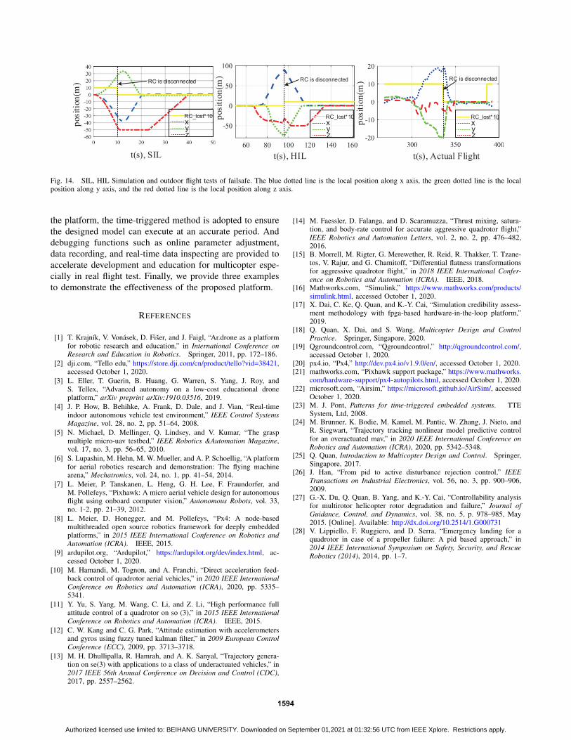
The result in SIL simulation is shown in Fig. 14(SIL).It can be observed that, during 0-10s, the multicopter isin MANUAL FLIGHT MODE. After 10s, the RC is lost,and the altitude is less than the threshold. As the logicwe designed, the multicopter first climbs up to the safealtitude we set, then enters RTL MODE. The return processis completed at 18s, with the horizontal position being (0,0). Then, the multicopter enters AUTO-LANDING MODEand finally completes landing at 39s.
After the HIL simulation further verifies the correctnessof the model, the real flight is performed. To ensure safety,the safe altitude set in the flight test is 5m. The final realflight curve is shown in Fig. 14(Actual Flight). At about335s, the RC is lost, then the multicopter rises to altitude5m, and returns to the HOME point horizontally. Finally,the multicopter lands with its altitude decreasing to 0. Thereal flight results show that multicopter can achieve failsafe.Based on the proposed platform, the designer only needsto design and improve the state machine in Simulink. Whatis more, Simulink can help to identify hidden errors in thedesigned state machine, like dead logic. This will facilitatethe design.
VI. CONCLUSIONSIn this paper, we introduce a rapid multicopter devel-
opment platform for education and research based on Pix-hawk/PX4 and MATLAB/Simulink. This platform supportsdevelopers to design controllers, estimators, decision-makingin MATLAB/Simulink for a conventional multicopter or newtype UAVs such as vertical takeoff and landing (VTOL),which can run in Pixhawk. The entire development consistsof three steps: SIL simulation, HIL simulation, and real flighttest. With this step-by-step development, safety and effi-ciency can be ensured. About the real-time performance of
1593
Authorized licensed use limited to: BEIHANG UNIVERSITY. Downloaded on September 01,2021 at 01:32:56 UTC from IEEE Xplore. Restrictions apply.
t(s), HIL
RC_lost*10xyz
t(s), SIL
posit
ion
(m)
posit
ion
(m)
posit
ion
(m)
t(s), Actual Flight
RC is disconnected RC is disconnected RC is disconnected
RC_lost*10xyz
RC_lost*10xyz
Fig. 14. SIL, HIL Simulation and outdoor flight tests of failsafe. The blue dotted line is the local position along x axis, the green dotted line is the localposition along y axis, and the red dotted line is the local position along z axis.
the platform, the time-triggered method is adopted to ensurethe designed model can execute at an accurate period. Anddebugging functions such as online parameter adjustment,data recording, and real-time data inspecting are provided toaccelerate development and education for multicopter espe-cially in real flight test. Finally, we provide three examplesto demonstrate the effectiveness of the proposed platform.
REFERENCES
[1] T. Krajnık, V. Vonasek, D. Fiser, and J. Faigl, “Ar.drone as a platformfor robotic research and education,” in International Conference onResearch and Education in Robotics. Springer, 2011, pp. 172–186.
[2] dji.com, “Tello edu,” https://store.dji.com/cn/product/tello?vid=38421,accessed October 1, 2020.
[3] L. Eller, T. Guerin, B. Huang, G. Warren, S. Yang, J. Roy, andS. Tellex, “Advanced autonomy on a low-cost educational droneplatform,” arXiv preprint arXiv:1910.03516, 2019.
[4] J. P. How, B. Behihke, A. Frank, D. Dale, and J. Vian, “Real-timeindoor autonomous vehicle test environment,” IEEE Control SystemsMagazine, vol. 28, no. 2, pp. 51–64, 2008.
[5] N. Michael, D. Mellinger, Q. Lindsey, and V. Kumar, “The graspmultiple micro-uav testbed,” IEEE Robotics &Automation Magazine,vol. 17, no. 3, pp. 56–65, 2010.
[6] S. Lupashin, M. Hehn, M. W. Mueller, and A. P. Schoellig, “A platformfor aerial robotics research and demonstration: The flying machinearena,” Mechatronics, vol. 24, no. 1, pp. 41–54, 2014.
[7] L. Meier, P. Tanskanen, L. Heng, G. H. Lee, F. Fraundorfer, andM. Pollefeys, “Pixhawk: A micro aerial vehicle design for autonomousflight using onboard computer vision,” Autonomous Robots, vol. 33,no. 1-2, pp. 21–39, 2012.
[8] L. Meier, D. Honegger, and M. Pollefeys, “Px4: A node-basedmultithreaded open source robotics framework for deeply embeddedplatforms,” in 2015 IEEE International Conference on Robotics andAutomation (ICRA). IEEE, 2015.
[9] ardupilot.org, “Ardupilot,” https://ardupilot.org/dev/index.html, ac-cessed October 1, 2020.
[10] M. Hamandi, M. Tognon, and A. Franchi, “Direct acceleration feed-back control of quadrotor aerial vehicles,” in 2020 IEEE InternationalConference on Robotics and Automation (ICRA), 2020, pp. 5335–5341.
[11] Y. Yu, S. Yang, M. Wang, C. Li, and Z. Li, “High performance fullattitude control of a quadrotor on so (3),” in 2015 IEEE InternationalConference on Robotics and Automation (ICRA). IEEE, 2015.
[12] C. W. Kang and C. G. Park, “Attitude estimation with accelerometersand gyros using fuzzy tuned kalman filter,” in 2009 European ControlConference (ECC), 2009, pp. 3713–3718.
[13] M. H. Dhullipalla, R. Hamrah, and A. K. Sanyal, “Trajectory genera-tion on se(3) with applications to a class of underactuated vehicles,” in2017 IEEE 56th Annual Conference on Decision and Control (CDC),2017, pp. 2557–2562.
[14] M. Faessler, D. Falanga, and D. Scaramuzza, “Thrust mixing, satura-tion, and body-rate control for accurate aggressive quadrotor flight,”IEEE Robotics and Automation Letters, vol. 2, no. 2, pp. 476–482,2016.
[15] B. Morrell, M. Rigter, G. Merewether, R. Reid, R. Thakker, T. Tzane-tos, V. Rajur, and G. Chamitoff, “Differential flatness transformationsfor aggressive quadrotor flight,” in 2018 IEEE International Confer-ence on Robotics and Automation (ICRA). IEEE, 2018.
[16] Mathworks.com, “Simulink,” https://www.mathworks.com/products/simulink.html, accessed October 1, 2020.
[17] X. Dai, C. Ke, Q. Quan, and K.-Y. Cai, “Simulation credibility assess-ment methodology with fpga-based hardware-in-the-loop platform,”2019.
[18] Q. Quan, X. Dai, and S. Wang, Multicopter Design and ControlPractice. Springer, Singapore, 2020.
[19] Qgroundcontrol.com, “Qgroundcontrol,” http://qgroundcontrol.com/,accessed October 1, 2020.
[20] px4.io, “Px4,” http://dev.px4.io/v1.9.0/en/, accessed October 1, 2020.[21] mathworks.com, “Pixhawk support package,” https://www.mathworks.
com/hardware-support/px4-autopilots.html, accessed October 1, 2020.[22] microsoft.com, “Airsim,” https://microsoft.github.io/AirSim/, accessed
October 1, 2020.[23] M. J. Pont, Patterns for time-triggered embedded systems. TTE
System, Ltd, 2008.[24] M. Brunner, K. Bodie, M. Kamel, M. Pantic, W. Zhang, J. Nieto, and
R. Siegwart, “Trajectory tracking nonlinear model predictive controlfor an overactuated mav,” in 2020 IEEE International Conference onRobotics and Automation (ICRA), 2020, pp. 5342–5348.
[25] Q. Quan, Introduction to Multicopter Design and Control. Springer,Singapore, 2017.
[26] J. Han, “From pid to active disturbance rejection control,” IEEETransactions on Industrial Electronics, vol. 56, no. 3, pp. 900–906,2009.
[27] G.-X. Du, Q. Quan, B. Yang, and K.-Y. Cai, “Controllability analysisfor multirotor helicopter rotor degradation and failure,” Journal ofGuidance, Control, and Dynamics, vol. 38, no. 5, p. 978–985, May2015. [Online]. Available: http://dx.doi.org/10.2514/1.G000731
[28] V. Lippiello, F. Ruggiero, and D. Serra, “Emergency landing for aquadrotor in case of a propeller failure: A pid based approach,” in2014 IEEE International Symposium on Safety, Security, and RescueRobotics (2014), 2014, pp. 1–7.
1594
Authorized licensed use limited to: BEIHANG UNIVERSITY. Downloaded on September 01,2021 at 01:32:56 UTC from IEEE Xplore. Restrictions apply.


![Laser-Odometrie für autonome Multicopter · MulticopterbietenhiereineschnelleDynamik,sindäußerstkostengünstigundwerdeninnaher ZukunftindiesenBereichenstärkerzumEinsatzkommen[9].](https://static.fdocuments.us/doc/165x107/5e106a1dd808077bf04199c5/laser-odometrie-fr-autonome-multicopterbietenhiereineschnelledynamiksinduerstkostengnstigundwerdeninnaher.jpg)