RF Communication Circuits - Sharifee.sharif.edu/~comm_cir-AliF/Note5.pdfWhat Types of Devices are...
29
RF Communication Circuits Lecture 5: Introduction to Network Analyzer
Transcript of RF Communication Circuits - Sharifee.sharif.edu/~comm_cir-AliF/Note5.pdfWhat Types of Devices are...

RF Communication Circuits
Lecture 5: Introduction to Network Analyzer

What Types of Devices are Tested?
Device type ActivePassive
Inte
grat
ion
Hig
hLo
w
Antennas
SwitchesMultiplexersMixersSamplersMultipliers
Diodes
DuplexersDiplexersFiltersCouplersBridgesSplitters, dividersCombinersIsolatorsCirculatorsAttenuatorsAdaptersOpens, shorts, loadsDelay linesCablesTransmission linesWaveguideResonators
DielectricsR, L, C's
RFICsMMICsT/R modulesTransceivers
ReceiversTunersConverters
VCAsAmplifiers
VCOsVTFsOscillatorsModulatorsVCAtten’s
Transistors

Lightwave Analogy to RF Energy
RF
Incident
Reflected
Transmitted
Lightwave
DUT

The Need for Both Magnitude and Phase
4. Time-domain characterization
Mag
Time
5. Vector-error correction
Error
MeasuredActual
2. Complex impedance needed to design matching circuits
3. Complex values needed for device modeling
1. Complete characterization of linear networks
High-frequency transistor model
Collector
Base
Emitter
S21
S12
S11 S22

Network Analyzer Basics Copyright 2000
Measuring S-Parameters
S 11 = ReflectedIncident
=b1a 1 a2 = 0
S 21 =Transmitted
Incident=
b2
a 1 a2 = 0
S 22 = ReflectedIncident
=b2a 2 a1 = 0
S 12 =Transmitted
Incident=
b1
a 2 a1 = 0
Incident TransmittedS 21
S 11Reflected
b 1
a 1
b 2
Z 0Load
a2 = 0DUTForward
IncidentTransmitted S 12
S 22Reflected
b2
a2b
a1 = 0DUTZ 0
Load Reverse
1
Network Analyzer Basics Copyright 2000
Equating S-Parameters with Common Measurement Terms
S11 = forward reflection coefficient (input match)S22 = reverse reflection coefficient (output match)S21 = forward transmission coefficient (gain or loss)S12 = reverse transmission coefficient (isolation)
Remember, S-parameters are inherently complex, linear quantities -- however, we often express them in a log-magnitude
format

Network Analyzer Basics Copyright 2000
High-Frequency Device Characterization
TransmittedIncident
TRANSMISSION
Gain / Loss
S-ParametersS21, S12
GroupDelay
TransmissionCoefficient
Insertion Phase
ReflectedIncident
REFLECTION
SWR
S-ParametersS11, S22 Reflection
Coefficient
Impedance, Admittance
R+jX, G+jB
ReturnLoss
Γ, ρΤ,τ
Incident
Reflected
TransmittedR BA
AR
=BR
=

Transmission ParametersVTransmittedV Incident
Transmission Coefficient = Τ =VTransmitted
V Incident= τ∠φ
DUT
Gain (dB) = 20 Log V Trans
V Inc
= 20 log τ
Insertion Loss (dB) = - 20 Log V Trans
V Inc
= - 20 log τ

Network Analyzer Basics Copyright 2000
Generalized Network Analyzer Block Diagram
RECEIVER / DETECTOR
PROCESSOR / DISPLAY
REFLECTED(A)
TRANSMITTED(B)
INCIDENT (R)
SIGNALSEPARATION
SOURCE
Incident
Reflected
Transmitted
DUT
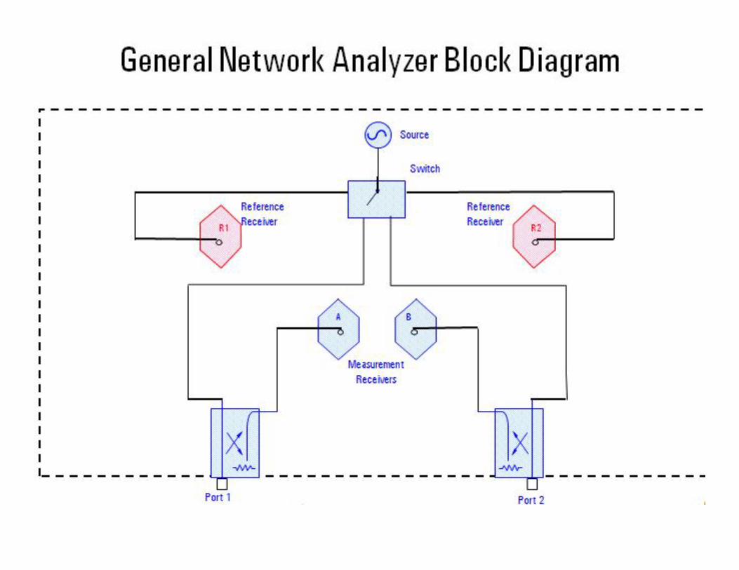

Network Analyzer full Block Diagram

Network Analyzer Basics Copyright 2000
T/R Versus S-Parameter Test Sets
l RF always comes out port 1
l port 2 is always receiverl response, one-port cal
available
l RF comes out port 1 or port 2
l forward and reverse measurements
l two-port calibration possible
Transmission/Reflection Test Set
Port 1 Port 2
Source
B
R
A
DUTFwd
Port 1 Port 2
Transfer switch
Source
B
R
A
S-Parameter Test Set
DUTFwd RevPort 1
Transfer switch
Port 2
Source
B
R1
A
R2

Block diagram for basic measurements

Example of testing High Power Amplifiers


Network Analyzer Basics Copyright 2000
Frequency Sweep - Filter TestCH1 S11 log MAG 5 dB/ REF 0 dB
CENTER 200.000 MHz SPAN 50.000 MHz
Return loss
log MAG 10 dB/ REF 0 dBCH1 S21
START .300 000 MHz STOP 400.000 000 MHz
Cor
69.1 dB Stopband
rejection
Insertion loss
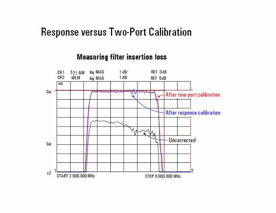
SCH1 21 log MAG 1 dB/ REF 0 dB
Cor
Cor
START 2 000.000 MHz STOP 6 000.000 MHzx2 1 2
m1: 4.000 000 GHz -0.16 dBm2-ref: 2.145 234 GHz 0.00 dB
1
ref 2
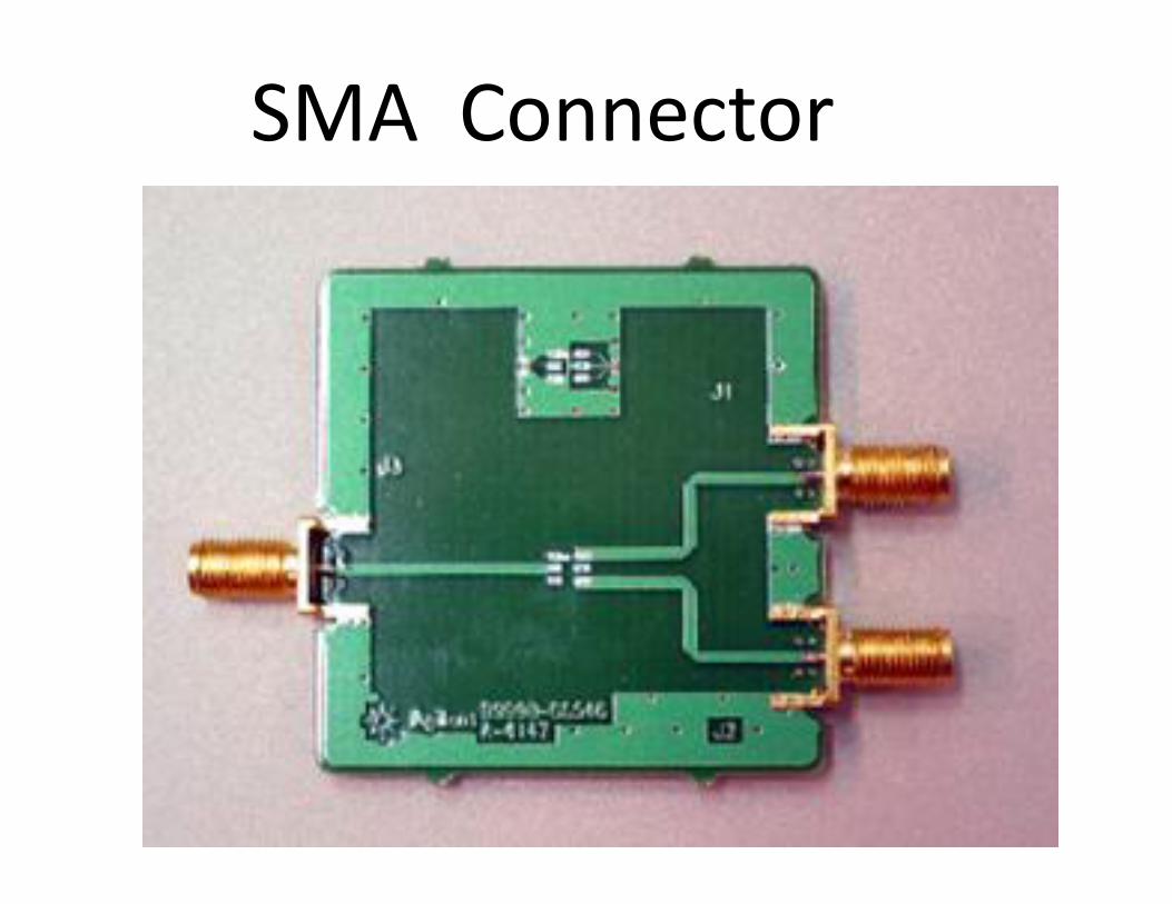
SMA Connector


Practical Example
Ap7 Connector

50 Ohm Termination

Short / Open Connector

At First:

50 Ohm Match Without Calibration

Calibrated: Open

Calibrated: Short

Calibrated: 50 Ohm


![TS06 6-Channel Self Calibration Capacitive Touch Sensortouchsemi.com/Pages/30_I2C_e/TS06_(6CH_Sensor_I2C)… · · 2016-06-04capacitance range [Note5] CS - - 100 ㎊ Minimum detective](https://static.fdocuments.us/doc/165x107/5ab05c917f8b9abc2f8b5756/ts06-6-channel-self-calibration-capacitive-touch-6chsensori2c2016-06-04capacitance.jpg)