Rexroth VisualMotion 9 Multi-Axis Motion Control Edition ... · PDF fileRexroth VisualMotion 9...
334
R911292839 Edition 02 Rexroth VisualMotion 9 Multi-Axis Motion Control using GPP and GMP Firmware Application Manual Industrial Hydraulics Electric Drives and Controls Linear Motion and Assembly Technologies Pneumatics Service Automation Mobile Hydraulics
Transcript of Rexroth VisualMotion 9 Multi-Axis Motion Control Edition ... · PDF fileRexroth VisualMotion 9...
R911292839Edition 02
Rexroth VisualMotion 9Multi-Axis Motion Controlusing GPP and GMP Firmware
Application Manual
IndustrialHydraulics
Electric Drivesand Controls
Linear Motion andAssembly Technologies Pneumatics
ServiceAutomation
MobileHydraulics

About this Documentation VisualMotion 9 Application Manual
DOK-VISMOT-VM*-09VRS**-AW02-EN-P
VisualMotion 9
Multi-Axis Motion Control
using GPP and GMP Firmware
Application Description
DOK-VISMOT-VM*-09VRS**-AW02-EN-P
Box, z.B. Box, 49-02V-EN
Info for Document Author, z.B. Ablagevermerk
Document Number, z.B. 209-0049-4306-02/EN
This documentation describes:
• PPC-R control using GPP and GMP firmware with non-coordinated,coordinated and electronic line shafting motion capabilities
• Motion program creation using VisualMotion Toolkit
• Fieldbus interfaces: Profibus, DeviceNet, ControlNet, EtherNet andInterbus
• VisualMotion communication servers
Description ReleaseDate
Notes
01 06/2003 First Release
02 10/2003 Second Release
2001 Rexroth Indramat GmbH
Copying this document, giving it to others and the use or communicationof the contents thereof without express authority, are forbidden. Offendersare liable for the payment of damages. All rights are reserved in the eventof the grant of a patent or the registration of a utility model or design(DIN 34-1).
The specified data is for product description purposes only and may notbe deemed to be guaranteed unless expressly confirmed in the contract.All rights are reserved with respect to the content of this documentationand the availability of the product.
Rexroth Indramat GmbHBgm.-Dr.-Nebel-Str. 2 • D-97816 Lohr a. Main • GermanyTel.: +49 (0)93 52/40-0 • Fax: +49 (0)93 52/40-48 85 • Telex: 68 94 21
Bosch Rexroth Corporation • Electric Drives and Controls5150 Prairie Stone Parkway • Hoffman Estates, IL 60192 • USATel.: 847-645-3600 • Fax: 847-645-6201http://www.boschrexroth.de/Dept. ESG4 (EAN)
This document has been printed on chlorine-free bleached paper.
Title
Type of Documentation
Document Typecode
Internal File Reference
Purpose of Documentation
Record of Revisions
Copyright
Validity
Published by
Note

VisualMotion 9 Application Manual Table of Contents I
DOK-VISMOT-VM*-09VRS**-AW02-EN-P
Table of Contents
1 VisualMotion 9 Overview 1-1
1.1 System Overview........................................................................................................................... 1-1
1.2 GPP 9 System Overview ............................................................................................................... 1-1
GPP 9 System Components.................................................................................................... 1-2
GPP 9 PLC Support ................................................................................................................ 1-2
GPP 9 Interface Support ......................................................................................................... 1-2
Drive I/O Support ..................................................................................................................... 1-3
1.3 GMP 9 System Overview............................................................................................................... 1-3
GMP 9 Firmware Features ...................................................................................................... 1-4
GMP 9 System Components ................................................................................................... 1-4
GMP 9 Interface Support......................................................................................................... 1-4
Drive I/O Support ..................................................................................................................... 1-4
2 VisualMotion Toolkit Installation 2-1
2.1 Overview........................................................................................................................................ 2-1
2.2 System Requirements ................................................................................................................... 2-1
2.3 Installing VisualMotion Toolkit 9.0 ................................................................................................. 2-2
3 Communication Servers 3-1
3.1 Overview........................................................................................................................................ 3-1
3.2 Establish Communication using VisualMotion Toolkit ................................................................... 3-1
Changing the Baud Rate ......................................................................................................... 3-3
Serial Communication ............................................................................................................. 3-3
Ethernet Interface .................................................................................................................... 3-4
PCI Communication................................................................................................................. 3-6
3.3 Scalable Communication Platform (SCP) Server .......................................................................... 3-6
Configuring the SCP Server .................................................................................................... 3-7
3.4 VisualMotion DDE (VM DDE) Server .......................................................................................... 3-14
3.5 OPC Communication for SCP ..................................................................................................... 3-24
Features of the OPC Server .................................................................................................. 3-25
OPC Communication............................................................................................................. 3-27
Sample OPC Clients.............................................................................................................. 3-33
3.6 DDE Communication for SCP...................................................................................................... 3-33
3.7 DDE Communication for VisualMotion ........................................................................................ 3-33
DDE Client Interfaces ............................................................................................................ 3-39
Creating and Customizing a DDE Client Interface with Microsoft Excel ............................ 3-39
Creating and Customizing a DDE Client Interface with Wonderware InTouch® ................... 3-44
4 Motion Types 4-1
4.1 Introduction .................................................................................................................................... 4-1
II Table of Contents VisualMotion 9 Application Manual
DOK-VISMOT-VM*-09VRS**-AW02-EN-P
Non-Coordinated Motion ......................................................................................................... 4-1
Coordinated Motion ................................................................................................................. 4-1
Electronic Line Shafting (ELS)................................................................................................. 4-2
5 VisualMotion Programming 5-1
5.1 VisualMotion Operating States ...................................................................................................... 5-1
Service Mode........................................................................................................................... 5-1
Project Mode............................................................................................................................ 5-1
Synchronizing a Project........................................................................................................... 5-2
5.2 Creating a New Project.................................................................................................................. 5-3
Project Values.......................................................................................................................... 5-8
Project Variables...................................................................................................................... 5-8
Step 1: Create the Initialization Task.................................................................................... 5-10
Step 2: Create Task A .......................................................................................................... 5-13
Step 3 Create the Subroutine ................................................................................................ 5-21
5.3 Downloading a Project................................................................................................................. 5-22
I/O Mapper............................................................................................................................. 5-22
Register and Bit Labels ......................................................................................................... 5-24
Placing a Project in Online Mode .......................................................................................... 5-26
5.4 Activating a Project ...................................................................................................................... 5-27
I/O Box................................................................................................................................... 5-27
Activating A Project With Register Bits.................................................................................. 5-27
Saving a Project..................................................................................................................... 5-32
Opening Existing Icon Programs........................................................................................... 5-33
5.5 Advanced Programming with Events........................................................................................... 5-34
Event Types........................................................................................................................... 5-38
5.6 Service Mode............................................................................................................................... 5-53
6 Electronic Line Shafting (ELS) 6-1
6.1 ELS Overview ................................................................................................................................ 6-1
6.2 Assigning Variable and Register Labels........................................................................................ 6-3
Virtual Master, ELS System Master, and ELS Group Default Registers................................. 6-4
Assigning Program Variables .................................................................................................. 6-5
Virtual Master 1 & 2 Default Register Labels .......................................................................... 6-6
ELS System Master Default Registers .................................................................................... 6-7
ELS System Master Configuration Word................................................................................. 6-9
ELS Group 1- 8 Default Register Labels ............................................................................... 6-13
ELS Group Configuration Word............................................................................................. 6-17
6.3 Virtual Master............................................................................................................................... 6-20
Assigning Initial Values.......................................................................................................... 6-21
Virtual Master Modes of Operation........................................................................................ 6-24
6.4 Real Master.................................................................................................................................. 6-25
Positioning a Secondary Encoder Signal .............................................................................. 6-26
6.5 ELS System Master ..................................................................................................................... 6-27
6.6 ELS Group Master ....................................................................................................................... 6-28
Cascading ELS Groups ......................................................................................................... 6-28
VisualMotion 9 Application Manual Table of Contents III
DOK-VISMOT-VM*-09VRS**-AW02-EN-P
6.7 Link Ring Master.......................................................................................................................... 6-29
6.8 Slip Monitoring for ELS System Masters ..................................................................................... 6-30
Slip Monitoring Variables....................................................................................................... 6-33
Using Register Bits to Adjust Slip Monitoring Feature........................................................... 6-33
6.9 ELS Group ................................................................................................................................... 6-34
ELS Group Slave Configuration ............................................................................................ 6-36
Stop and Jog Variables, Compile Time Setup....................................................................... 6-36
Switching Synchronization between Group Input Masters.................................................... 6-38
Synchronized “Lock On/Lock Off” of ELS Group Master ...................................................... 6-51
Phase Control ........................................................................................................................ 6-53
Initialization Control ............................................................................................................... 6-54
6.10 Editing ELS Groups and System Masters Online........................................................................ 6-55
7 Program Debugging and Monitoring 7-1
7.1 Finding Program Problems............................................................................................................ 7-1
Test Code ................................................................................................................................ 7-1
7.2 Control Compiler Base Code ......................................................................................................... 7-2
Base Code instruction mnemonics and valid arguments ........................................................ 7-2
7.3 Icon Language Warnings and Error Messages ........................................................................... 7-15
7.4 Text Language Error Messages .................................................................................................. 7-16
First Pass Errors .................................................................................................................... 7-17
Second Pass Compiler Errors ............................................................................................... 7-17
8 Drive Tools 8-1
8.1 Overview........................................................................................................................................ 8-1
DriveTop .................................................................................................................................. 8-1
8.2 Determining Drive Direction........................................................................................................... 8-1
Drive Operation Modes............................................................................................................ 8-4
Drive Scaling............................................................................................................................ 8-5
Homing the Drive..................................................................................................................... 8-6
Travel Limits for Software and Hardware (End Switches – checking safety features of drivesetup)....................................................................................................................................... 8-8
9 Profibus Fieldbus Interface 9-1
9.1 General Information ....................................................................................................................... 9-1
PPC-R System Description with a Fieldbus ............................................................................ 9-1
The VisualMotion Fieldbus Mapper ......................................................................................... 9-2
Data Transfer Direction (Output vs. Input) .............................................................................. 9-2
Fieldbus Data Channel Descriptions ....................................................................................... 9-2
9.2 Fieldbus Mapper Functionality....................................................................................................... 9-7
Initializing the Fieldbus Mapper from VisualMotion 9 .............................................................. 9-7
Editing a Fieldbus Mapper....................................................................................................... 9-8
Fieldbus Slave Definition ......................................................................................................... 9-8
Fieldbus Slave Configuration................................................................................................... 9-9
Cyclic Data Configuration ...................................................................................................... 9-10
Additional Functions .............................................................................................................. 9-13
9.3 Information for the GPP Programmer.......................................................................................... 9-15

IV Table of Contents VisualMotion 9 Application Manual
DOK-VISMOT-VM*-09VRS**-AW02-EN-P
Fieldbus Status ...................................................................................................................... 9-15
Fieldbus Diagnostics ............................................................................................................. 9-16
Fieldbus/PLC Cyclic Read/Write Monitoring ......................................................................... 9-16
Fieldbus Error Reaction......................................................................................................... 9-17
9.4 Information for the PLC Programmer .......................................................................................... 9-18
*.gsd File................................................................................................................................ 9-18
Multiplexing............................................................................................................................ 9-18
Non-Cyclic Data Access via the Parameter Channel ............................................................ 9-23
10 DeviceNet, ControlNet, and EtherNet/IP Fieldbus Interfaces 10-1
10.1 General Information ..................................................................................................................... 10-1
PPC-R System Description with a Fieldbus .......................................................................... 10-1
The VisualMotion Fieldbus Mapper ....................................................................................... 10-2
Data Transfer Direction (Output vs. Input) ............................................................................ 10-3
Fieldbus Data Channel Descriptions ..................................................................................... 10-3
10.2 Fieldbus Mapper Functionality..................................................................................................... 10-7
Initializing the Fieldbus Mapper from VisualMotion 9 ............................................................ 10-7
Creating a New Fieldbus Mapper File ................................................................................... 10-7
Importing a Fieldbus Mapper File .......................................................................................... 10-8
Fieldbus Slave Definition ....................................................................................................... 10-9
Fieldbus Slave Configuration............................................................................................... 10-11
Cyclic Data Configuration .................................................................................................... 10-14
Additional Functions ............................................................................................................ 10-17
10.3 Information for the GPP Programmer........................................................................................ 10-19
Fieldbus Status .................................................................................................................... 10-19
Fieldbus Diagnostics ........................................................................................................... 10-20
Fieldbus/PLC Cyclic Read/Write Monitoring ....................................................................... 10-20
Fieldbus Error Reaction....................................................................................................... 10-20
10.4 Information for the PLC Programmer ........................................................................................ 10-22
*.eds File.............................................................................................................................. 10-22
Word and Byte Swapping .................................................................................................... 10-22
Multiplexing.......................................................................................................................... 10-22
Non-Cyclic Data (Explicit Messaging) ................................................................................. 10-27
11 Interbus Fieldbus Interface 11-1
11.1 General Information ..................................................................................................................... 11-1
PPC-R System Description with a Fieldbus .......................................................................... 11-1
The VisualMotion Fieldbus Mapper ....................................................................................... 11-2
Data Transfer Direction (Output vs. Input) ............................................................................ 11-2
Fieldbus Data Channel Descriptions ..................................................................................... 11-2
11.2 Fieldbus Mapper Functionality..................................................................................................... 11-7
Initializing the Fieldbus Mapper from VisualMotion 9 ............................................................ 11-7
Creating a New Fieldbus Mapper File ................................................................................... 11-7
Importing a Fieldbus Mapper File .......................................................................................... 11-7
Fieldbus Slave Definition ....................................................................................................... 11-9
Fieldbus Slave Configuration................................................................................................. 11-9
VisualMotion 9 Application Manual Table of Contents V
DOK-VISMOT-VM*-09VRS**-AW02-EN-P
Cyclic Data Configuration .................................................................................................... 11-10
Additional Functions ............................................................................................................ 11-14
11.3 Information for the GPP Programmer........................................................................................ 11-15
Fieldbus Status .................................................................................................................... 11-15
Fieldbus Diagnostics ........................................................................................................... 11-17
Fieldbus/PLC Cyclic Read/Write Monitoring ....................................................................... 11-17
Fieldbus Error Reaction....................................................................................................... 11-17
11.4 Information for the PLC Programmer ........................................................................................ 11-19
Multiplexing.......................................................................................................................... 11-19
Non-Cyclic Data Access via the Non-Cyclic (PCP) Channel .............................................. 11-23
12 Index 12-1
13 Service & Support 13-1
13.1 Helpdesk ...................................................................................................................................... 13-1
13.2 Service-Hotline............................................................................................................................. 13-1
13.3 Internet......................................................................................................................................... 13-1
13.4 Vor der Kontaktaufnahme... - Before contacting us... ................................................................. 13-1
13.5 Kundenbetreuungsstellen - Sales & Service Facilities ................................................................ 13-2

VI Table of Contents VisualMotion 9 Application Manual
DOK-VISMOT-VM*-09VRS**-AW02-EN-P

VisualMotion 9 Application Manual VisualMotion 9 Overview 1-1
DOK-VISMOT-VM*-09VRS**-AW02-EN-P
1 VisualMotion 9 Overview
1.1 System Overview
VisualMotion is a programmable multi-axis motion control system capableof controlling up to 40 intelligent digital drives from Bosch Rexroth. ThePC software used for motion control management is named VisualMotionToolkit.
VisualMotion 9 supports the following hardware form factors and firmwareversions:
• PPC-R (RECO-version) using GPP 9 firmware
• PPC-P11.1 (PCI-version) using GMP 9 firmware
1.2 GPP 9 System Overview
The PPC-R is a stand-alone multi-axis motion control. It has theRECO02 form factor, a form factor used by Bosch Rexroth for motioncontrols, PLCs and I/O modules. These devices share the RECO02back-plane bus for data exchange.
VisualMotion motion control is recommended for use with BoschRexroth's DIAX04 and/or ECODRIVE03 digital servo drives. Thecommunication between control and digital servo drives is performedusing the SERCOS fiber optic interface, the international standard forreal-time communication for digital servo drives.
VisualMotion can provide multi-axis coordinated or non-coordinatedmotion control with tightly integrated RECO02 I/O logic control functions.The flexibility of GPP 9 firmware supports a variety of applications, fromgeneral motion control to sophisticated multiple master electronic lineshafting (ELS) and robotics.
�
�
�
�
�
�
�
�
�
��
��
��
��
��
��
��
��
���
��
���
������
�� �
� ���
�����������
������������������
��
�� �
� ���
��� �����
���
���
�����������
��
�� ������� �����
�� � �� �
���������
�
���
�� �� �
��
����
����
����������������
��
�
�
���������
�����
���������
�
���
�� �����
����������������
��
�
�
���������
�����
��
��
��
����
�� �� ��
����
PPCR_Overview.FH7
Fig. 1-1: PPC-R Motion Control

1-2 VisualMotion 9 Overview VisualMotion 9 Application Manual
DOK-VISMOT-VM*-09VRS**-AW02-EN-P
GPP 9 System ComponentsThe VisualMotion GPP 9 system has the following components:
• PPC-R control using GPP 9 firmware
• RECO02 I/O modules (Local and SERCOS)
• VisualMotion Toolkit (VMT) software for motion control programming,parametrization, system diagnostics and motion control management.VMT also includes DDE and OPC servers. These servers provide thecommunication protocol between Windows programs and the control.
• Up to 40 intelligent digital drives can be connected to one control overthe SERCOS fiber optic ring
– DIAX04 (using SSE03 or ELS05 firmware) drives and motors
– ECODRIVE03 (using SMT02, SGP01, SGP03 or SGP20firmware) drives and motors
– ECODRIVE C (using MPG01 firmware) drives and motors
• HMI interfaces (BTC06, BTV04, BTV05, BTV06)
GPP 9 PLC SupportThe Bosch Rexroth MTS-R is a PLC unit that interfaces with theVisualMotion control (PPC-R) and is available pre-configured in two sizes.
• MTS-R01.1 with one expansion slot
• MTS-R02.1 with three expansion slot
Note: The expansion slot(s) on the MTS-R can be configured withfieldbus master interface or serial interface cards.
GPP 9 Interface SupportVisualMotion GPP 9 supports the following interfaces:
Fieldbus Interfaces• Profibus-DP slave interface (32 words)
• Interbus slave interface (16 words)
• DeviceNet, ControlNet or EtherNet/IP slave interface (32 words)
Note: When using EtherNet/IP in a VisualMotion 9 system, no otherfieldbus interface card (i.e., Profibus, DeviceNet, ControlNet,Interbus) or the MTS-R PLC interface can be installed.
EtherNet/IP uses firmware version FMC-ETH01*-PHT-02VRS-NN.
Note: The word size in parentheses indicates the maximum numberof words allowed in the cyclic telegram for both the Input andOutput directions.

VisualMotion 9 Application Manual VisualMotion 9 Overview 1-3
DOK-VISMOT-VM*-09VRS**-AW02-EN-P
Additional Interfaces:• Option Card Programmable Limit Switch (16 or 32 outputs)
• Link Ring for Master/Slave interfacing of VisualMotion controls
• Ethernet Interface
Note: The same EtherNet hardware is used for both EtherNet/IPfieldbus and standard EtherNet TCP/IP networkingcommunication. When enabled as an EtherNet/IP fieldbusinterface in VisualMotion 9 using GPP 9 firmware, standardTCP/IP communication between VisualMotion Toolkit over thesame network is possible.
Drive I/O SupportBosch Rexroth digital drives support the following I/O devices:
• DEA0x.2M (x = 4, 5 or 6) I/O cards for DIAX04 digital drives
• EMD I/O module using the EcoX interface for DKC22.3 digitaldrives using SGP20 firmware
1.3 GMP 9 System Overview
The PPC-P11.1 (PCI-version) is a PC-based stand-alone multi-axismotion control. The GMP 9 firmware used with the PPC-P is designed towork as a complete motion control solution. A host PC containing a LogicController (SoftPLC) handles the system logic, fieldbus and Ethernetcommunications.
Just like the PPC-R, the PPC-P supports Bosch Rexroth DIAX04 andECODRIVE03 digital servo drives. Communication between the controland digital servo drives is performed via the SERCOS fiber opticinterface.
ppc_pci.tif
Fig. 1-2: PPC-P (PCI-version) Motion Control

1-4 VisualMotion 9 Overview VisualMotion 9 Application Manual
DOK-VISMOT-VM*-09VRS**-AW02-EN-P
GMP 9 Firmware FeaturesAll firmware functionality supported in GPP 9 will also be supported inGMP 9 with the following restrictions:
• VisualMotion fieldbus slave interfaces are not supported. If fieldbuscommunication is required, the SoftPLC must be equipped tocommunicate with a PC-based fieldbus card. The PPC-P cyclicchannel (real-time communication to/from DPR) is configured usingVisualMotion Toolkit's Fieldbus Mapper.
• Ethernet interface is not supported
GMP 9 System ComponentsThe VisualMotion GMP 9 system is composed of the followingcomponents:
• PPC-P control using GMP firmware
• SERCOS RECO02 I/O modules
• VisualMotion Toolkit (VMT) software for motion control programming,parametrization, system diagnostics and motion control management.VMT also includes DDE and OPC servers. These servers provide thecommunication protocol between Windows programs and the control.
• Up to 40 intelligent digital drives can be connected to one control overthe SERCOS fiber optic ring
– DIAX04 (using SSE03 or ELS05 firmware) drives and motors
– ECODRIVE03 (SMT02, SGP01, SGP03 and SGP20 firmware)drives and motors
– ECODRIVE C (using MPG01 firmware) drives and motors
• HMI interfaces (BTC06, BTV04, BTV05, BTV06)
Note: When using VisualMotion's I/O Setup tool to assign registersto physical outputs, the location (either input or outputregisters) will determine which device is the “master” of theparticular set of physical outputs. If they are mapped to thePPC output section, then the PPC will have control of theoutputs. If they are mapped to the PPC input section, then theSoftPLC will have control over the physical outputs.
GMP 9 Interface SupportVisualMotion GMP 9 supports the following interfaces:
• Optional Programmable Limit Switch Card (16 or 32 outputs).
• Link Ring for Master/Slave interfacing of VisualMotion controls.
Drive I/O SupportBosch Rexroth digital drives support the following I/O devices:
• DEA0x.2M (x = 4, 5 or 6) I/O cards for DIAX04 digital drives
• EMD I/O module using the EcoX interface for DKC22.3 digitaldrives using SGP20 firmware

VisualMotion 9 Application Manual VisualMotion Toolkit Installation 2-1
DOK-VISMOT-VM*-09VRS**-AW02-EN-P
2 VisualMotion Toolkit Installation
2.1 Overview
VisualMotion Toolkit (VMT) is supplied on CD-ROM format. It is installedwith dual language support in English and German. A complete helpsystem is available as part of the installation, which contains detailedinformation about VisualMotion, including diagnostic and context sensitiveinformation, accessible through the F1 key or Help button. DuringVisualMotion installation, DriveTop software for commissioning drives isautomatically installed.
Note: The version of DriveTop in VisualMotion 9 (09E10) willoverwrite any previous version of DriveTop installed on yourcomputer with the user ID and password from the existingversion of DriveTop.
2.2 System Requirements
The following system specifications are recommended for runningVisualMotion 9 software.
ComputerVisualMotion Toolkit can be installed on any IBM™ PC compatiblePentium computer with the following specifications:
• Windows NT 4 with service pack 6 or Windows 2000
• Internet Explorer 4.0 or later
• 64 MB of RAM system memory
• Complete dual language (English and German) installation includinghelp system requires 95 MB of hard disk space. Additional space isrequired for user files.
DisplayA VGA display is required. A color monitor display makes it possible totake full advantage of VisualMotion's graphic interface.
PrinterVMT uses the default printer installed on your computer. For optimalresolution, especially when printing projects, use a high-resolution (300-dpi) laser or ink jet printer.
MouseA serial or PS2 mouse is required to use the VMT’s Icon programmingenvironment.
Serial I/OVMT can be configured to use the PC's serial port for communicationbetween the host PC and the PPC-R. An IKB0005 RS-232 serial cable isrequired between the host PC and the PPC-R X10 or X16 communicationports. Hardware handshaking is not used.

2-2 VisualMotion Toolkit Installation VisualMotion 9 Application Manual
DOK-VISMOT-VM*-09VRS**-AW02-EN-P
2.3 Installing VisualMotion Toolkit 9.0
To install VisualMotion Toolkit:
1. Insert the VisualMotion CD into the CD-Rom drive. VisualMotion willautomatically start.
2. Select the setup language.
The install program will prompt you to select either the English or Germaninstallation language version from the drop-down menu. This option canbe changed at any time after installation by selecting Tools ⇒ Optionsfrom VisualMotion Toolkit's main menu..
Note: If the language selected in VisualMotion does not match thelanguage of the computer’s operating system, some windowsin VisualMotion will maintain the operating system language.
VisualMotion's splash screen will be displayed while an InstallShieldWizard launches. The wizard will guide you through the rest of the setupprocess.
If your computer currently has a previous version of VisualMotion 9installed on it, the setup program will recognize the software and launch amodify, repair, and remove wizard. By selecting the Repair option (seeFig. 2-1), you can overwrite the files of the existing VisualMotioncomponents with the files of the new version. This will not affect theprograms you have created with the earlier version. Programs saved onyour computer’s hard drive can be downloaded to the new version ofVisualMotion.

VisualMotion 9 Application Manual VisualMotion Toolkit Installation 2-3
DOK-VISMOT-VM*-09VRS**-AW02-EN-P
Install_Repair.tif
Fig. 2-1: Modify, Repair, Remove VisualMotion Components
3. Click Next> in the Welcome window.
4. Click Yes in the license window to continue with the installation.
5. Enter a user name, company name, and serial number in theCustomer Information window.
Note: The serial number is printed on the software packagingmaterial.
6. Accept the default folder location for VisualMotion software by clickingNext, or change the default location by clicking the Browse… button.
Install_Destination.tif
Fig. 2-2: Installation Destination Location
7. Select the Installation setup type. The Setup window allows you tochoose from 3 different installation types. The amount of hard diskspace required for the program is dependent upon the setup typeselected.

2-4 VisualMotion Toolkit Installation VisualMotion 9 Application Manual
DOK-VISMOT-VM*-09VRS**-AW02-EN-P
Install_Setup_Type.tif
Fig. 2-3: Installation Setup Type
The Typical setup option installs a default set of the most commonlyused VisualMotion components. The Compact option, designed toconserve hard drive space, installs the minimum required options to runVisualMotion. The Custom setup option allows you to install individualsoftware components. The following table outlines how much hard diskspace is needed per setup type.
Type of Setup Description Required Hard disk Space
Compact Required files, no help files 7.2 MB
Custom User-selectable installation depends on selection, 7.2 – 36.6 MB
Typical (English) Required files and English help files 36.6 MB
Typical (German) Required files and German help files 36.6 MB
Table 2-1: Setup Types
8. Select the installation folder location where the software will reside onyour hard drive.
9. When the installation is complete, you will be prompted to restart yourcomputer.

VisualMotion 9 Application Manual Communication Servers 3-1
DOK-VISMOT-VM*-09VRS**-AW02-EN-P
3 Communication Servers
3.1 Overview
VisualMotion 9 supports two communication servers, the VisualMotionDynamic Data Exchange server (VM DDE) and a scalable communicationplatform (SCP). SCP uses the SIS protocol, a Bosch Rexroth-specificbinary protocol, to communicate with the PPC over Ethernet, serial, orPCI-Bus connection. The OPC interface in SCP uses the OPC protocol tocommunicate with a client such as a Windows based HMI client software,while the VM DDE interfaces uses ASCII protocol to communicate withVisualMotion or PC based HMIs.
This chapter discusses how to configure the communication servers Thebasic features of each server are listed in the following table:
Feature VisualMotion DDEServer (VM DDE)
ScalableCommunicationPlatform (SCP)
DDE interface Yes Yes
OPC Interface No Yes
Serial Communication Yes Yes
Ethernet Communication Yes Yes
PCI-Bus Communication No Yes
GPP7-GPP8 Support Yes No
GPP9-GMP9 Support Yes Yes
Table 3-1: SCP and VM DDE Features
3.2 Establish Communication using VisualMotion Toolkit
With VisualMotion Toolkit (VMT) installed on your PC, verifycommunication with the following procedure:
1. Open VisualMotion and select View and edit control data in“Service” mode.
2. Select Diagnostics ⇒ System from the VisualMotion menu
If proper communication has been established, the Status tab in theSystems Diagnostics window (shown in Fig. 3-1) will display the operatingstate.

3-2 Communication Servers VisualMotion 9 Application Manual
DOK-VISMOT-VM*-09VRS**-AW02-EN-P
System_Diagnostics_Status.tif
Fig. 3-1: System Diagnostics Window
If the communication link has failed, an error will be issued. Either thereis a problem with the physical connection or the communication settingsdo not match the settings of the DDE Server. To establish a connection:
3. Click on the Settings button in the error message window to open theSerial Communications window (Fig. 3-2).
Serial_Comm.tif
Fig. 3-2: Serial Communication
4. Select the baud rate setting in the Serial Communications window thatmatches the baud rate setting in the control
5. To view the current baud rate settings in the control, depress the S1button on the faceplate of the control 3 times. To display the baudrate of the X16 connector, depress the S1 button 5 times.
6. Check the status of the system again as described in step 2 to verifythat to verify that communication has been established.

VisualMotion 9 Application Manual Communication Servers 3-3
DOK-VISMOT-VM*-09VRS**-AW02-EN-P
Changing the Baud RateAfter communication has been established between VisualMotion and thecontrol, the baud rate setting can be changed. To change the baud rate:
1. Open the Control Settings window by selecting Tools ⇒ ControlSettings….
2. Select either the X10 Program Port tab or X16 Communication Porttab.
The tabs can only be viewed when your project is in Online mode orVisualMotion is in Service Mode because serial communicationparameters are not stored in the project when it is offline.
3. Select the new baud rate setting from the drop-down menu.
Change_Baud_Rate.tif
Fig. 3-3: Baud Rate Selection
4. Cycle the power to the control.
After cycling the power, the new baud rate is shown in the control window.
5. Open the Control Settings window in VisualMotion.
When attempting to open the Control Settings window after cycling power,The DDE server error window is displayed.
6. Click the Settings button in the error message window. This will openthe Serial Communications window.
7. Change the baud rate to match the baud rate in the control
The new baud rate is displayed in the Control Settings window.
Serial CommunicationVisualMotion is installed with a serial connection by default. Theconnection can be used to establish communication with the control.
Both serial ports are configured to respond to the VisualMotion ASCIIHost Protocol and SIS protocol (the format is auto-detected by thefirmware and can be dynamic). The serial port on the PPC-R01.2faceplate can also be configured to communicate with the Bosch Rexroth

3-4 Communication Servers VisualMotion 9 Application Manual
DOK-VISMOT-VM*-09VRS**-AW02-EN-P
BTC06 VT* interface if no additional cards are used. Both ports alwaysoperate with:
• 8 bits per character
• 1 stop bit
The configurable communication settings are shown in the following table:
Serial Com Options Baud RateChecksum(ASCII Protocol)
Main port default 9600 enabled
Main port valid settings300, 1200, 2400, 4800, 9600,19200, 38400, 57600,115200
enabled ordisabled
Optional port default 9600 enabled
Optional port validsettings
300, 1200, 2400, 4800, 9600,19200, 38400, 57600,115200
enabled ordisabled
Table 3-2: Configurable Communication Settings
Ethernet InterfaceThe Ethernet option card resides in the PPC-R control and contains it'sown TCP/IP (Transmission Control Protocol/Internet Protocol) stack. TheTCP/IP stack enables the Ethernet interface to transmit data over thenetwork or Internet and communicate with VisualMotion Toolkit via theDDE Server.
Ethernet Card SetupBefore an Ethernet card can be accessed, the following controlparameters must be configured in the Parameter Overview window.
• C-0-0400 – Card IP Address
• C-0-0401 – Card Subnet Mask
• C-0-0402 – Card Gateway IP Address
• C-0-0403 – Half / Full Duplex Mode
• C-0-0405 – Card Network Password
In addition to the setup parameters, the following read-only parametersare supported:
• C-0-0404 – Card Network Access Control (read-only via Ethernet)
Note: When communicating over a serial connection, parameterC-0-0404, Card Access Network Control, can be directlymodified by entering the desired network access level(No Access, Read, ReadWrite).
When communicating over an Ethernet connection, thenetwork access level is changed every time the password inC-0-0405, Card Network Password, is entered in C-0-0404.
• C-0-0406 – CIF Ethernet Card Hardware ID
• C-0-0407 – CIF Ethernet Card Firmware Version
• C-0-0408– CIF Driver version string

VisualMotion 9 Application Manual Communication Servers 3-5
DOK-VISMOT-VM*-09VRS**-AW02-EN-P
The following steps are used to configure an Ethernet card via a serialconnection (IKB0005) to VisualMotion Toolkit.
1. Power up the control, with a connected Ethernet card, and startVisualMotion Toolkit.
2. Open VisualMotion Toolkit in Service mode and select Data ⇒Parameters to open the Parameter Overview-Project window.
3. Modify control parameter C-0-0400 and enter the Ethernet card's IPAddress in dot notation, for example "172.18.11.205".
4. Modify control parameter C-0-0401 and enter the Ethernet card'sSubnet Mask in dot notation, for example "255.255.0.0".
5. Modify control parameter C-0-0402 and enter the Ethernet card'sGateway IP Address in dot notation, for example "172.16.1.1".
Every Ethernet card must have a unique IP Address assigned.
6. Modify control parameter C-0-0403 and set the transmission mode toeither half duplex or full duplex. Typing "HALF" or "FULL" inuppercase letters modify this parameter.
Full-duplex (20 Mbps) can only be achieved if connecting to the Ethernetcard via a LAN switch.
Optional: Modify control parameter C-0-0405 and enter an alphanumericnetwork password, up to 20 characters, that will be used to modify theaccess level to the control.
Note: When connected to the control via an Ethernet connection, thepassword in control parameter C-0-0405 is displayed withasterisks. Only the user with serial access to the control canview the actual text password and modify it if desired.
7. Close VisualMotion Toolkit and cycle power to the control in order forthese changes to take affect.
After the control is powered up, the LEDs on the faceplate of the Comport card will have the following behavior: RDY LED should be on, andthe RUN and STA LED's should flash continuously.
Ethernet RegistersThe following VisualMotion registers monitor and provide the status ofethernet communications for diagnostic purposes:
• Register 50 – Ethernet status. The bits in this register indicate astatus of the interface and the current message being processed.
• Bit 1 – Indicates the interface is present
(0 = not present, 1 = present)
• Bit 9 – A request has been received and the Ethernet callbackfunction is executing.
• Bit 10 – Response is pending. The message is being processedby the motion control (GPP).
• Bit 11 – The message processing is complete.
• Bit 12 – The response message has been sent to the DDE Server.
• Bit 13 – Sets when a failure to communicate request to GPPEthernet handler exists.
• Bit 16 – An invalid protocol has been received (standard orencrypted ASCII).
• Register 51 – Standard message count. This register indicates thenumber of messages that have been received in standard ASCII

3-6 Communication Servers VisualMotion 9 Application Manual
DOK-VISMOT-VM*-09VRS**-AW02-EN-P
protocol. It is a 16-bit integer and will rollover when the maximum isreached.
• Register 52 – Cyphered message count. This register indicates thenumber of messages that have been received in encrypted ASCIIprotocol. It is a 16-bit integer and will rollover when the maximum isreached.
• Register 53 – Invalid count. This register indicates the number ofmessages that have been received in which the protocol cannot bedetermined. It is a 16-bit integer and will rollover when the maximumis reached.
Refer to the VisualMotion 9 Functional Description manual for additionalinformation on ASCII protocol.
PCI CommunicationThe firmware for the PPC-PCI1.1 is designed to work in a completesystem solution consisting of a Logic Controller (Soft PLC) and MotionController (PPC-PCI) inside an industrial PC with an HMI package.
On the PC, there are three main interfaces with the PPC: a soft PLC,VisualMotion, and HMI packages such as WinHMI or WonderWare. Thesoft PLC will have direct access to the DPR (dual port RAM), whileVisualMotion and the HMI packages will communicate over the DPR viathe Scalable Communication Platform (SCP).
VisualMotion Toolkit supports a PCI card with GMP firmware. GMPfirmware supports all the functionality of the GPP firmware with thefollowing exceptions:
• Data Mapper is not supported, thus eliminating the option of orderingthe corresponding PC104 interface boards with this system. Theparent soft control (softPLC) communicates directly to the PPC-P11.1via the DPR over the PCI bus. If additional fieldbus connectivity isrequired, the soft control (softPLC) should be equipped with thecapability to communicate with a PC-resident fieldbus card. The DataMapper software utility is used to set up PCI cyclic channels. PC104fieldbus slave cards are not supported.
• The Register and Cyclic channels over the Dual Port RAM use thesame cycle time defined for the I/O mapper (2 or 4 ms)
• I/O setup only consists of SERCOS Reco I/O, ECO-X I/O, and DIAX04drive I/O.
3.3 Scalable Communication Platform (SCP) Server
The SCP has two communication interfaces, SCP-DDE Server and OPC.This server allows communication between a PPC-R or PPC-P andVisualMotion Toolkit or Windows based HMI software programs. TheSCP-DDE Server interface of the server is used for communication withthe VisualMotion Toolkit. For Windows based HMI software, the OPCinterface and the SCP-DDE Sever can be used.
Note: The Wonderware HMI, OPCLink in INTouch version 7, doesnot work with the VisualMotion 9 OPC server. Refer to theWonderware website for information on upgrading to OPCLinkversion 7.6 to use the OPC server.
The following figure is a model of the SCP server, illustrating it’s link tothe PPC-R and PPC-P.

VisualMotion 9 Application Manual Communication Servers 3-7
DOK-VISMOT-VM*-09VRS**-AW02-EN-P
DDE OPC
SCP
PPC-R
GPP 9
SIS Protocol via RS232,RS485 or Ethernet TCP/IP
VisualMotionWindows based
HMI software
PC
ASCII Format OPC
PPC-P11.1
GMP 9
VisualMotion DDE
PPC-R
GPP 7, 8 and 9
ASCII Protocol via RS232,RS485 or Ethernet TCP/IP
VisualMotionWindows based
HMI software
PC
ASCII Format
PPC-P11.1
GMP 9
ASCII Protocolvia RS232 or RS485
SIS Protocol via RS232,RS485 or PCI Bus
ASCII Protocol SIS Protocol
Fig. 3-4: ASCII and SIS Communication Overview
With SCP, it is possible for multiple clients to communicatesimultaneously through the server. The SCP converts the multiple formsof communication into a universal protocol, the SIS protocol, tocommunicate with the PPC-R over an Ethernet, serial, or PCI-Busconnection (refer to the VisualMotion 9 Functional Description for moreinformation on SIS protocol).
Configuring the SCP ServerSCP and applications to support SCP and OPC communication areautomatically installed with VisualMotion 9 software, including:
• DDESCP.exe
• OPCClient.exe
• OPCScp.exe
• ScpServer.exe
• ScpSyscon.exe
• TraceMonitor
These components are installed in the default folder location,C:\Indramat\VisualMotion9\SCP\Bin.
ScpSyscon.exe is a program used to configure the SCP server. To runthe program:
1. Double-click the ScpSyscon.exe file.
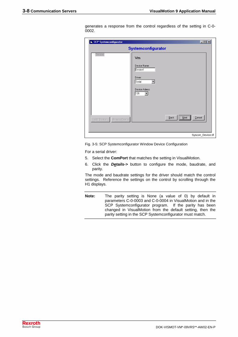
2. In the SCP Systemconfigurator window, click Add Device.
3. VisualMotion will be the only device available, click Next.
4. Configure the device by entering a name, address, and connectiontype (Ethernet, PCI, or Serial).
The device address should match the address listed in the C-0-0002parameter in the control or in the control display where it appears as theunit number. The device address 128 is a point-to-point connection which
3-8 Communication Servers VisualMotion 9 Application Manual
DOK-VISMOT-VM*-09VRS**-AW02-EN-P
generates a response from the control regardless of the setting in C-0-0002.
Syscon_Device.tif
Fig. 3-5: SCP Systemconfigurator Window Device Configuration
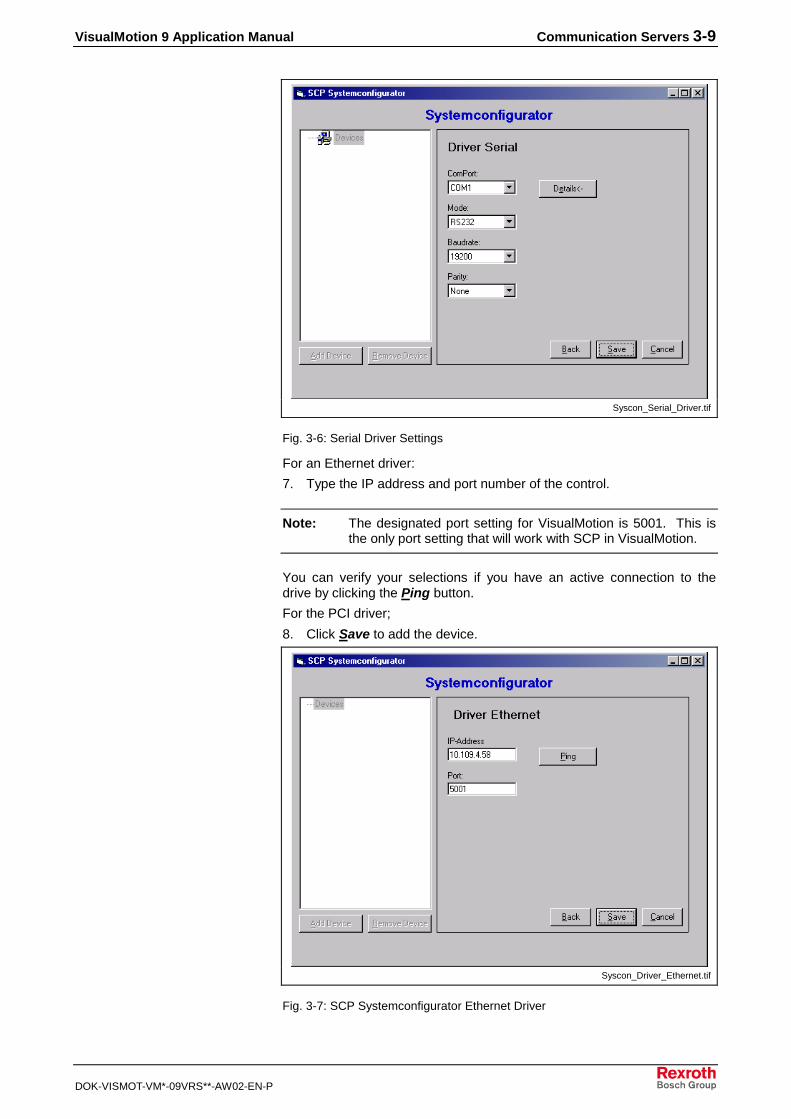
For a serial driver:
5. Select the ComPort that matches the setting in VisualMotion.
6. Click the Details-> button to configure the mode, baudrate, andparity.
The mode and baudrate settings for the driver should match the controlsettings. Reference the settings on the control by scrolling through theH1 displays.
Note: The parity setting is None (a value of 0) by default inparameters C-0-0003 and C-0-0004 in VisualMotion and in theSCP Systemconfigurator program. If the parity has beenchanged in VisualMotion from the default setting, then theparity setting in the SCP Systemconfigurator must match.
VisualMotion 9 Application Manual Communication Servers 3-9
DOK-VISMOT-VM*-09VRS**-AW02-EN-P
Syscon_Serial_Driver.tif
Fig. 3-6: Serial Driver Settings
For an Ethernet driver:
7. Type the IP address and port number of the control.
Note: The designated port setting for VisualMotion is 5001. This isthe only port setting that will work with SCP in VisualMotion.
You can verify your selections if you have an active connection to thedrive by clicking the Ping button.
For the PCI driver;
8. Click Save to add the device.
Syscon_Driver_Ethernet.tif
Fig. 3-7: SCP Systemconfigurator Ethernet Driver

3-10 Communication Servers VisualMotion 9 Application Manual
DOK-VISMOT-VM*-09VRS**-AW02-EN-P
A driver configuration can be modified by selecting the device and thenthe Change Config button. The Driver type and Device address can bemodified, including the settings for the ComPort.
Note: To change the Device Name, highlight the device in the treestructure and click Remove Device. Add the device againwith the new name using the Add Device button.
OPCClientOPCClient is a sample client interface that can be used to test thecommunication link with the SCP server. By referencing the name of theSCP server that was configured with the Systemconfigurator, theOPCClient provides the interface to add groups and items to build thedata structure recognized by the SCP server. The data structurehierarchy is composed of groups and items in the format illustrated in Fig.3-8.
OPC_Server_Data_Structure.tif
Fig. 3-8: OPC Server Data Structure
The OPCClient.exe file is located in the Bin folder in the Rexroth folder onyour hard drive at the following location: C:\Rexroth\VisualMotion9\SCP\Bin. The program is started by double-clicking the folder. It openswith the OPCClient window which contains tabs for the separateconfiguration fields.

VisualMotion 9 Application Manual Communication Servers 3-11
DOK-VISMOT-VM*-09VRS**-AW02-EN-P
OPCClient_Server_List.tif
Fig. 3-9: OPC Server List
The server is assigned groups and each group is assigned items. Theconfiguration is not retained when the OPCClient window is closed withoutstoring it on the PC using the OPC Save button and reloading it using theOPC Load button in the OPCClient window.
Configure GroupTo configure a group:
1. Select the Connect button to establish a connection to the OPCserver.
2. Select the IOPCServer tab and click AddGroup.
OPCClient_IOPCServer.tif
Fig. 3-10: OPC IOPCServer Tab

3-12 Communication Servers VisualMotion 9 Application Manual
DOK-VISMOT-VM*-09VRS**-AW02-EN-P
3. Type the group name and review the default settings for theremainder of the fields in the tab and change where appropriate.
Note: The value for the Requested Update Rate sets theAsynchronous update rate.
4. Click Add Group and then OK to close the field.
Configure ItemTo add an item to a group:
1. Select the IOPCItemMgt tab in the OPCClient window.
2. Highlight the group you want to add the item to and click the Selectbutton.
3. Click the AddItems button to activate the item configuration fields.
4. Select the Type from the following items in the drop-down menu:
• VT_EMPTY
• VT_12
• VT_14
• VT_R4
• VT_R8
• VT_BSTR
• VT_BOOL
• VT_DATE
5. Type the Item ID and Access Path (Access Path = SCP.OPC).
Note: The item ID includes the target drive name followed by SCPsyntax command code. Refer to the “OPC Communication”section in this chapter for more information.
OPCClient_AddItems.tif
Fig. 3-11: OPCClient IOPCItemMgt Tab

VisualMotion 9 Application Manual Communication Servers 3-13
DOK-VISMOT-VM*-09VRS**-AW02-EN-P
6. Click AddItem and the item will be displayed in the Group field.
7. Click OK to return to the IOPCItemMgt tab.
The data type can be reconfigured by selecting the SetDataTypes buttonwith the item highlighted in the Group field.
The hierarchy structure is displayed in the OPC SCP Server window.
OPC_SCP_Server.tif
Fig. 3-12: OPC SCP Server Window
The number of items configured for the highlighted group is listed in theright window, but the individual items are not displayed.
Read and Write AccessBoth Synchronous and Asynchronous read and write access is availableto and from the OPC server. Two tabs in the OPC Client window allowyou to set the rates and display the results.

3-14 Communication Servers VisualMotion 9 Application Manual
DOK-VISMOT-VM*-09VRS**-AW02-EN-P
OPCClient_IOPCAsyncIO2ReadWrite.tif
Fig. 3-13: IOPCAsyncIO2 Read Write Tab
To activate Asynchronous Read and Write:
1. Highlight the group and click Select.
The details of the items in the group are displayed in the group field.
2. Highlight the item and click Read to obtain the value at the momentwhen the button was selected.
The write button will open a dialog box where a value can be entered forwriting to the server. The read and write values are displayed in the fieldat the bottom of the OPCClient window.
TraceMonitorThe TraceMonitor is a Bosch Rexroth internal tool for monitoring anddebugging SCP communication. The TraceMonitor program is openedfrom the location, C:\Rexroth\VisualMotion9\SCP\Bin. It is possible tomonitor and analyze the data exchange between the SCP and clientapplications (such as VisualMotion and Visual Basic clients). Moreinformation will be available when the development of this program iscomplete.
3.4 VisualMotion DDE (VM DDE) Server
The VM DDE server supports network communication over an Ethernetbus. The network connection method and target control name and IPaddress set in VisualMotion Toolkit, is used by the VM DDE server toinitiate a connection-oriented path with the motion control (GPP). Fig. 3-4illustrates the communication between a host PC and the control viaEthernet.
VisualMotion DDE Server SettingsCommunication between VisualMotion Toolkit and an Ethernet-readycontrol is performed via the DDE Server. The following steps outline theDDE Server setup procedure.

VisualMotion 9 Application Manual Communication Servers 3-15
DOK-VISMOT-VM*-09VRS**-AW02-EN-P
1. Start VisualMotion Toolkit and launch the DDE Server shown in thefigure below by selecting Tools ⇒ Registered Tools ⇒ CLC_DDE.
dde_server.tif
Fig. 3-14:VM DDE Server Window
2. Select Settings ⇒ Network Communications from the DDE Serverto open the Network Communications window below.
net_comm.tif
Fig. 3-15:Network Communications Window
3. Click the Add button to add a network configuration.
4. In the Add Network Configuration window below, enter the followinginformation:
• A label (up to 20 characters) that identifies the control.
• The control's Ethernet IP Address in dot notation, for example"172.18.11.205".
Note: The Comm Timeout and Time to Live (TTL) default valuescan be modified if desired.
The Enable Message Encryption feature encrypts messagesbefore transporting them to the control, providing another layerof security.

3-16 Communication Servers VisualMotion 9 Application Manual
DOK-VISMOT-VM*-09VRS**-AW02-EN-P
add_net_config.tif
Fig. 3-16: Add Network Configuration Window
5. Click the OK button to return to the Network Communication windowwhere the new configuration will be displayed.
Note: The order in which configurations are added to the NetworkCommunication window determines the control's card number.
net_comm_done.tif
Note: A maximum of 32 network connections are allowed in theNetwork Communication window. A DDE Server message willbe issued if the Add button is pressed for an 11 connection.
6. Checking the Enable NCA option from the Network Communicationwindow enables the Network Communication Accelerator. Thisfeature accelerates communication to the control by creating an openmessage loop between VisualMotion Toolkit.
7. Click OK to return the DDE Server main window.
Establishing Communication between DDE Server andVisualMotion ToolkitWith the DDE Server configured, perform the following steps to initiatecommunication to an Ethernet-ready control via VisualMotion Toolkit.
1. Start VisualMotion Toolkit and select Tools ⇒ Control Selection…to open the Control Selection window below.

VisualMotion 9 Application Manual Communication Servers 3-17
DOK-VISMOT-VM*-09VRS**-AW02-EN-P
Control_Selection.tif
Fig. 3-17: Control Selection Window
2. Select Network as the Connection Method from the drop-down list.
3. Select the label of the control you are connecting to from the drop-down list in the Target field.
The IP address for the control selected will appear in the Target field afterthe Control Selection window has been closed and reopened. Theaddress can be edited or a new address can be added by selecting theConfigure… button, which opens the Network Communications window.
Note: The control’s card number is determined in the order in whichit was added to the Network Communications window, startingwith 0.
When a project is downloaded to the control, the DDE Server is activated,unless an error occurs during the download. The Network Connection InProgress window, shown in Fig. 3-18, is displayed during communicationinitialization.
net_comm_inprogress.tif
Fig. 3-18: Network Connection Status
Once communication is established, the VM DDE Server window opensand VisualMotion Toolkit can access the control based on the accesslevel set in control parameter C-0-0404, Card Access Network Control.
The status of the project after it has been downloaded to the control isdisplayed in the VM DDE Server window. Errors are also indicated, forexample, if an error has occurred during download of phase transition.

3-18 Communication Servers VisualMotion 9 Application Manual
DOK-VISMOT-VM*-09VRS**-AW02-EN-P
The window can also be displayed while the project is offline, by selectingTools ⇒ Registered Tools ⇒ CLC_DDE from the VisualMotion Toolkitmenu.
The VM DDE Server window displays diagnostic messages indicating thestate of the control, including any errors that occur while the control isrunning. Fig. 3-19 shows the status message and number for ParameterMode.
DDE_Param_Mode.tif
Fig. 3-19: DDE Server Parameter Mode
If a parameter error occurs, it will be displayed in the VM DDE Serverwindow, for example, the shutdown message 400 EMERGENCY STOP,as shown in Fig. 3-20.
DDE_EStop.tif
Fig. 3-20: DDE Server Emergency Stop
VM DDE Monitoring CapabilitiesThe VM DDE Server has several options for viewing communication links.The Monitor menu in the VM DDE Server window contains the DDEConversations, DDE Communications, and Network Monitor interfaceswhere display options can be set.
dde_monitor.tif
Fig. 3-21: The Monitor Menu
DDE ConversationsThe DDE Conversations window displays the Conversation, Service andTopic Handles for all of the current DDE conversations. The Item Countcolumn shows the total number of active advise links, request

VisualMotion 9 Application Manual Communication Servers 3-19
DOK-VISMOT-VM*-09VRS**-AW02-EN-P
transactions and poke transactions. An item transaction list can beviewed by selecting a conversation entry and clicking the Propertiesbutton.
dde_conv_list.tif
Fig. 3-22: DDE Conversations
DDE Conversation ItemThe DDE Conversation Item window displays the item transaction list fora conversation. The Service name, Topic string, Item, Format, andTransaction Type are displayed in text format. Use the Next andPrevious buttons to cycle through the Item field, if there is more than oneitem in the conversation.
dde_conv_item.tif
Fig. 3-23: DDE Conversation Item
DDE Communications
Selecting Monitor DDE ⇒ Communications opens the Monitor window.The Monitor window displays all current information being transferred toand from the PPC.
The active window builds a communication log of all DDE conversationsthat occur while the monitor is running. Selecting Clear will empty the log.Selecting Stop will stop the conversation monitoring, allowing you to scrollthrough the log. The Monitor window can be resized to enlarge the activeviewing area.

3-20 Communication Servers VisualMotion 9 Application Manual
DOK-VISMOT-VM*-09VRS**-AW02-EN-P
dde_comm_monitor.tif
Fig. 3-24: DDE Communication Monitor
Network MonitorsThe Network Monitors menu has several options for; monitoring datatransfer of connected configurations, determining accessible IPAddresses on the network, and testing network communication of aspecific IP Address.
dde_monitor_net.tif
Fig. 3-25: Network Monitors
Connections
Selecting Monitor ⇒ Network Monitors ⇒ Connections in the VM DDEServer window opens the Connections window. From this window, youcan monitor data transfer statistics, performance statistics, and errorcounts if the DDE Server is actively communicating with the device.

VisualMotion 9 Application Manual Communication Servers 3-21
DOK-VISMOT-VM*-09VRS**-AW02-EN-P
monitor_net_conn.tif
Fig. 3-26: Monitor Network Communications
Map View
Selecting Monitor ⇒ Network Monitors ⇒ Map View from the VM DDEServer main menu opens the Control Network Map window. This windowis used to locate active controls within a network Subnet IP Address.
Note: The Map View feature is not available for Windows 98/95
Entering a valid Subnet IP Address and clicking the Start button will findall active Ethernet-ready controls and display them as a green G. TheTimeout field represents the maximum time needed to determine whethera connection has been established. If all known connections aredisplayed, click the Stop button to terminate the search. The yellow Brepresents the broadcast address for the given Subnet.

3-22 Communication Servers VisualMotion 9 Application Manual
DOK-VISMOT-VM*-09VRS**-AW02-EN-P
monitor_net_map.tif
Fig. 3-27: Control Network Map
Double clicking on a green G, opens the Control Card Query windowshown in Fig. 3-28. From this window, the user can view the control'ssystem configuration as well as the control's network information.
card_query.tif
Fig. 3-28: Control Card Query
Right clicking on a green G opens a small pop-up window, where you canadd the selected control. Selecting Add Configuration opens the ModifyNetwork Configuration window, shown in Fig. 3-23. From this window,you can modify the Label that will appear in the Network Communicationwindow located under the VM DDE Server's menu selection, Settings ⇒Network Communications.
Card Query
Add Configuration

VisualMotion 9 Application Manual Communication Servers 3-23
DOK-VISMOT-VM*-09VRS**-AW02-EN-P
Note: This feature is equivalent to selecting the Add button on theNetwork Communication window when adding a newconfiguration to the VM DDE Server.
add_config.tif
Fig. 3-29: Add Configuration
Diagnostics
Selecting Monitor ⇒ Network Monitors ⇒ Diagnostics from the VMDDE Server main menu opens the Connection Diagnostics window.From this window the user can test the network communication for acontrol listed in the Available Configurations drop-down list. Each testreturns a message indicating if the test passed or failed. In addition tonetwork testing, the user can also trace the route of the networkconnection for the selected control.

3-24 Communication Servers VisualMotion 9 Application Manual
DOK-VISMOT-VM*-09VRS**-AW02-EN-P
conn_diag.tif
Fig. 3-30: Connection Diagnostics
This test verifies that the PC's network interface is operational.
Note: This test is not available for Windows 98/95.
This test verifies that the DDE Server can communicate with the Ethernetcard in the control.
Note: This test is not available for Windows 98/95.
This test verifies that the DDE Server can communicate with the GPPfirmware in the control via the control's Ethernet card.
This button opens the Trace Route window, which maps the route of themessage through routers from the DDE server to the control.
Note: This feature is not available for Windows 98/95.
3.5 OPC Communication for SCP
The OPC communication protocol has the following structure:
<SCP Device Name><SCP-Command>
The SCP Device Name represents the local connection name. Becauseit is possible to have more than one control interfacing the SCP server,each connection must have a unique SCP device name. The mostcommon SCP Command types (parameter, variable, register, event,point, program, control, PID, and zone) are discussed in the followingsection.
Local Loopback Test
CIF Hardware Loopback Test
GPP Loopback Test
Trace Route

VisualMotion 9 Application Manual Communication Servers 3-25
DOK-VISMOT-VM*-09VRS**-AW02-EN-P
Features of the OPC ServerThe OPC server portion of the SCP supports the following interfaces:
• Data Access Custom Interface Standard Version 2.04 (September 5,2000)
• Data Access Automation Interface Standard Version 2.02 (February4, 1999) and OPC Common Definitions and Interface Version 1.0(October 27,1998) with Release 01V01.
Note: The following interfaces are currently not supported:
• Browsing of available items
• Tree namespace
• Public groups
• OPC Security
• Alarms and Events
• Historical Data Access
The following server types are available:
• Local InProc Server
• Local OutProc Server
• Remote Server
The following tables contain the interfaces supported by the OPC server.Additional information about the interfaces is available in the OPCspecification document. The command field column in the table indicatesthe related chapter in the OPC specification.
Interface Method Optional Supported CommentAddGroup Yes
GetErrorString Yes
GetGroupByName Yes
GetStatus Yes
RemoveGroup Yes
IOPCServer
CreateGroupEnumerator Yes
IOPCServerPublicGroups
Yes No
Yes partial The interface supports just „FLATSpace“
QueryOrganization Yes
ChangeBrowsePosition Yes No Is not supported because it is just “FLATSpace” supported
BrowseOPCItemIDs No
IOPCBrowseServerAddressSpace
GetItemIDBrowseAccessPaths
Yes No This interface is not supported becausethere are no AccessPath supported, seealso IOPCItemMgt
New in Version 2.0 of the OPCSpecification
QueryAvailableProperties Yes
GetItemProperties Yes
IOPCItemProperties
LookupItemIDs Yes
Specifications
Server Types
Interfaces

3-26 Communication Servers VisualMotion 9 Application Manual
DOK-VISMOT-VM*-09VRS**-AW02-EN-P
Interface Method Optional Supported CommentSetLocaleID Yes Yes New in Version 2.0 of the OPC
Specification
GetLocaleID Yes
QueryAvailableLocaleIDs Yes
GetErrorString Yes
IOPCCommon
SetClientName Yes
Interface Method Optional Supported CommentNew in Version 2.0 of the OPCSpecificationConnectPointContainer of theIOPCShutdown interface
EnumConnectionPoints Yes
IConnectionPoinContainer
FindConnectionPoint Yes
IPersistFile Yes No
Table 3-3: OPCServer–Object Interfaces
Interface Method Optional Supported Comment
GetState Yes
SetState Yes
SetName Yes
IOPCGroupStateMgt
CloneGroup Yes
IOPCPublicGroupStateMgt
Yes No
Read Yes
Write Yes
Refresh2 Yes
Cancel2 Yes
SetEnable Yes
IOPCASyncIO2New in Version 2.0(OPC Specification)
GetEnable Yes
IOPCAsyncIO Yes No Just in Version 1.0 of the OPC Specification
AddItems Yes
ValidateItems Yes
RemoveItems Yes
SetActiveState Yes
SetClientHandles Yes
SetDatatypes Yes
IOPCItemMgt
CreateEnumerator Yes
IConnectionPointContainer
New in Version 2.0 of the OPC SpecificationConnectPointContainer of theIOPCDataCallback
EnumConnectionPoints Yes
FindConnectionPoint Yes
Read YesIOPCSyncIO
Write Yes

VisualMotion 9 Application Manual Communication Servers 3-27
DOK-VISMOT-VM*-09VRS**-AW02-EN-P
Interface Method Optional Supported Comment
IDataObject Yes No
IEnumOPCItemAttributes
Next Yes
Skip Yes
Reset Yes
Clone Yes
Fig. 3-1: Interfaces and Methods of the OPCGroup
OPC CommunicationThe OPC communication protocol has the following structure:
<SCP Device Name><SCP-Command>
• The SCP Device Name is configured with Syscon, the OPCconfiguration interface.
• The SCP-Command accesses different data in the motion control.The SCP Commands are explained more in detail in this chapter.
ParameterVX1X2,X3,X4,X5
V VisualMotion
X1 Parameter type (D, C, T, or A)
X2 Data type (A, B, D, H, L, P, T, U)
X3 Parameter set number - the drive, axis, or task numberdepending on the parameter type accessed. The parameter setis always zero for card parameters.
X4 Parameter number (integer format) – the S-parameter numbersstart at zero. The P parameters numbers have an offset of32768 (for example, the parameter number for P-0-0001 is32769).
X5 Number of elements (integer format)
Note: List parameter access information is not available at this time.This information will be available at a later date.
Parameter Type Data Type
D - Drive Parameter (S and P Parameter)
A - Attributes (hex)
C - Card Parameter H - Upper limit (mixed)
T - Task Parameter L - Lower limit (mixed)
A - Axis Parameter P - Data (mixed)
T - Parameter name (string)
U - Unit text (string)
Table 3-4: Parameter SCP Command Syntax
VisualMotion,VDL,1,125 Access the lower limit of drive parameter S-0-0125, of Drive number 1, from the device “VisualMotion”
SCP Command Syntax
Examples

3-28 Communication Servers VisualMotion 9 Application Manual
DOK-VISMOT-VM*-09VRS**-AW02-EN-P
EventVEX1,X2,X3
V VisualMotion
E Event table
X1 Data type (S, T, D,A, F,M, or L)
X2 Program number in decimal format (0 indicates active program)
X3 Event number 1 to n in decimal format (n is determined throughthe offline VisualMotion data table)
Data Type Description
S Status, integer data
T Type, integer data
D Direction, integer data
A Argument, float data
F Function, string data
M Message, string data
L Array format, string data
Table 3-5: Event SCP Command Syntax
VisualMotion,VEL,0,1 Access event entry (User program = 0, Event = 1)
VisualMotion,VEM,0,1 Access message of event 1 of the active program
VariableVX1X2,X3,X4
V VisualMotion
X1 Variable type (F, I, H, or G)
X2 Data type (P, X, or T)
X3 Program number in decimal format (0 indicates active program)
X4 Variable number 1 to n in decimal format (n is determinedthrough the offline VisualMotion data table)
Variable Type Description
F Program Floats
I Program Integers
H Global Floats
G Global Integers
Data Type
P Float/Integer data
X Hex data
T Label text
Table 3-6: Variable SCP Command Syntax
VisualMotion,VFP,0,1 Access floating-point F1 variable of the activeprogram
SCP Command Syntax
Examples
SCP Command Syntax
Examples
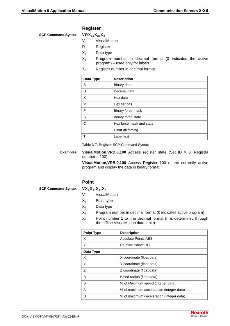
VisualMotion 9 Application Manual Communication Servers 3-29
DOK-VISMOT-VM*-09VRS**-AW02-EN-P
RegisterVRX1,X2,X3
V VisualMotion
R Register
X1 Data type
X2 Program number in decimal format (0 indicates the activeprogram) – used only for labels
X3 Register number in decimal format
Data Type Description
B Binary data
D Decimal data
X Hex data
M Hex set bits
F Binary force mask
S Binary force state
C Hex force mask and state
E Clear all forcing
T Label text
Table 3-7: Register SCP Command Syntax
VisualMotion,VRD,0,100 Access register state (Set ID = 0, Registernumber = 100)
VisualMotion,VRB,0,100 Access Register 100 of the currently activeprogram and display the data in binary format.
PointVX1X2,X3,X4
V VisualMotion
X1 Point type
X2 Data type
X3 Program number in decimal format (0 indicates active program)
X4 Point number 1 to n in decimal format (n is determined throughthe offline VisualMotion data table)
Point Type Description
X Absolute Points ABS
Y Relative Points REL
Data Type
X X coordinate (float data)
Y Y coordinate (float data)
Z Z coordinate (float data)
B Blend radius (float data)
S % of Maximum speed (integer data)
A % of maximum acceleration (integer data)
D % of maximum deceleration (integer data)
SCP Command Syntax
Examples
SCP Command Syntax

3-30 Communication Servers VisualMotion 9 Application Manual
DOK-VISMOT-VM*-09VRS**-AW02-EN-P
Point Type Description
J % jerk (integer data)
1 Event number to enable for this point (integer data)
2 Event number to enable for this point (integer data)
3 Event number to enable for this point (integer data)
4 Event number to enable for this point (integer data)
R Roll/Rate (float data)
P Pitch (float data)
W Yaw (float data)
E Elbow state (integer data)
L Array format (string) data
V Label list (string)
Table 3-8: Point SCP Command Syntax
VisualMotion,VXL,0,1 Access absolute point 1 from the active program.
VisualMotion,VXY,0,10 Access the y-coordinate of absolute point 10from the currently active program.
ProgramVPX1,X2,X3
V VisualMotion
P Program
X1 Subclass
X2 Program Number
X3 Set
Subclass Description Program Number Set
E Delete a program (integerdata)
0 0
H List of programs (string) 0 The elementof the list
A Activate a program(integer data)
0 0
N Program name (string) The actual programnumber
0
V List of program variables(string)
The actual programnumber
0
X Copy program data toanother program (integerdata)
The number of thesource program
0
J List of CAM INDEXERcontrol blocks (string)
0 CAM IDblocknumber
K Compress flash (integerdata)
0 0
Table 3-9: Program SCP Command Syntax
Examples
SCP Command Syntax

VisualMotion 9 Application Manual Communication Servers 3-31
DOK-VISMOT-VM*-09VRS**-AW02-EN-P
VisualMotion,VPN,10,0 Accesses the name of program 10.
Writing the program number to VisualMotion,VPE,0,0 deletes theprogram.
Writing the program number to VisualMotion,VPA,0,0 activates theprogram.
Writing the program number n to VisualMotion,VPX,4,0 copies theprogram data from program n to program 4.
Control PLSVWX1,X2,X3
V VisualMotion
W Control PLS
X1 Data type
X2 Program number – the number of the program from which data isbeing accessed (0 is the currently active program).
X3 PLS number
Data Type Description
O Phase offset (float data)
R Assigned output register (integer data)
M Assigned mask register (integer data)
T Master type (integer data)
A Master axis number (integer data)
H List of On, Off, and Lead time values (string)
E List of On values (float data)
F List of Off values (float data)
G List of lead-time values (integer data)
Table 3-10: Control PLS SCP Command Syntax
VisualMotion,VWM,1,2 Access the assigned mask register of controlPLS of program 1.
PIDVMX1,X2, X3
V VisualMotion
M PID
X1 Data type
X2 Program number – the number of the program from which data isbeing accessed (0 is the currently active program).
X3 PID number
Examples
SCP Command Syntax
Examples
SCP Command Syntax

3-32 Communication Servers VisualMotion 9 Application Manual
DOK-VISMOT-VM*-09VRS**-AW02-EN-P
Data Type Description
B Variables used (string data)
E Calculated set point (float data)
F Calculated feedback (float data)
G Calculated output (float data)
J Loop time (integer data)
L List of valid PID loop numbers (integer data)
R Control register (integer data)
S Status register (integer data)
T Type (integer data)
Table 3-11: PID SCP Command Syntax
VisualMotion,VMS,0,1 Access the number of the status register of PIDloop 1 of the currently active program.
ZoneVZX1,X2,X3
V VisualMotion
Z Zone
X1 Data type
X2 Program number 0 to 10 in decimal format (0 indicates currentprogram)
X3 Zone number 1 to n in decimal format (n is determined throughthe offline VisualMotion data table)
Data Type Description
S Status (integer data)
A Point 1 X coordinate (float data)
B Point 1 Y coordinate (float data)
C Point 1 Z coordinate (float data)
D Point 2 X coordinate (float data)
E Point 2 Y coordinate (float data)
F Point 2 Z coordinate (float data)
L Array format (string data)
Table 3-12: Zone SCP Command Syntax
VisualMotion,VZL,0,1 Access zone 1 array of the active program.
VisualMotion,VZA,0,3 Access the x-coordinate from zone 3 of thecurrently active program.
Examples
SCP Command Syntax
Examples

VisualMotion 9 Application Manual Communication Servers 3-33
DOK-VISMOT-VM*-09VRS**-AW02-EN-P
Sample OPC ClientsExamples of the Wonderware and VisualBasic clients can be installedwith VisualMotion if a custom installation is performed and the OPCSample Applications check box is selected. Reference documents forthese samples:
• Wonderware OPC Client for VisualMotion9
• VisualBasic Client for the Bosch Rexroth OPC Server with VM9
are installed in the file location:
C:\Rexroth\VisualMotion9\SCP\Samples
These documents contain information about source code, establishingcommunication to the OPC server, and reading and writing data to andfrom the OPC server.
3.6 DDE Communication for SCP
The SCP supports the DDE communication protocol so that aVisualMotion 9 project can communicate over a network, serial, or PCIconnection. SCP also provides HMI support of DDE communication. Theprotocol for the SCP-DDE server uses the same ASCII syntax that the VMDDE server uses. To establish communication, a Service, Topic, andItem name need to be specified. Their formats are:
Service Name: CLC_DDE. (for exchanging control data)
Topic Name: Device name defined in Systemconfigurator
Item Name: Direct ASCII serial protocol (identify the data to beexchanged.)
Refer to the VisualMotion 9 (GPP) Multi-Axis Motion Control FunctionalDescription for information about the ASCII protocol.
3.7 DDE Communication for VisualMotion
CLC_DDE is a Windows-based DDE Server application that is used tocommunicate with Bosch Rexroth’s GPP motion control. It has beenimplemented using Windows Dynamic Data Exchange ManagementLibrary (DDEML).
Features of the DDE server application include:
• Serial connection (RS232) to the control with support for an RS485auto switching adapter
• Network support via an Ethernet connection
• Access to server parameters and status through DDE
• Supports Request, Advise and Poke transactions
Dynamic Data Exchange InterfaceA Windows application, known as a client, can pass informationbetween other applications known as servers using DDE. A clientestablishes a conversation with a server specifying a Service and a Topic.Once a conversation has been started, a client may request or sendinformation by specifying an item.
Service NameThe control communication server supports the service name CLC_DDE.

3-34 Communication Servers VisualMotion 9 Application Manual
DOK-VISMOT-VM*-09VRS**-AW02-EN-P
Topic NameThe topic name identifies the method of connection to the control and theunit number. Valid strings consist of a communication device name and aunit number. Valid device names are SERIAL_, and network_ and validcard unit numbers are '0' to 'F'. Connections that use the CLC_FILEservice should specify the VisualMotion program file as the topic name. Ifthe file is not located in the same directory as clc_dde.exe then thecomplete path should be included. To exchange server data, the servicename should be CLC_DDE and the topic name should be SERIAL_0,which indicates a serial connection to a GPP control designated as unit 0.
Item NameThe item name identifies the specific data being exchanged. Whenexchanging control data, the item name consists of a string that containsthe class, subclass and data identifiers of the information for theGPS/GPP controller. The strings follow the ASCII serial protocol. Referto the VisualMotion 9 (GPP) Multi-Axis Motion Control FunctionalDescription for an explanation of ASCII codes. When exchanging serverdata, the item name should consist of the section and entry name fromthe INI file (clc_dde.ini). The two names must be divided by a pipe (‘|’)character. Not all server data has read/write capabilities, for example:
"RX 0.10" Specifies register 10 in hexadecimal format
"TP 2.20" Specifies task B parameter 20
"CP 1.122" Specifies card parameter 122
VM DDE ServerThe DDE Server is first launched when a request is made to the control.The DDE Server can be set to display the control’s unit number and currentstatus. In this mode, the DDE Server can act as a diagnostic window for thecontrol system.
The DDE Server is displayed as an icon on the Start toolbar when thewindow in Fig. 3-31 is minimized.
vm_dde.tif
Fig. 3-31: DDE Server
All settings for the DDE Server are performed from the menu selections inFig. 3-32.

VisualMotion 9 Application Manual Communication Servers 3-35
DOK-VISMOT-VM*-09VRS**-AW02-EN-P
dde_menus.tif
Fig. 3-32: DDE Server Menu Selections
The Settings MenuThe Settings menu is used to configure the DDE Server andcommunications for the types displayed in Fig. 3-33.
vm_dde_settings.tif
Fig. 3-33: The Settings Menu
Server ConfigurationThe Server Configuration window has settings for system parameters andprovides performance status information.

3-36 Communication Servers VisualMotion 9 Application Manual
DOK-VISMOT-VM*-09VRS**-AW02-EN-P
server_config.tif
Fig. 3-34: Server Configuration
The communications settings determine how the DDE Server window willdisplay communication status. Table 3-13 contains descriptions of thesettings:

VisualMotion 9 Application Manual Communication Servers 3-37
DOK-VISMOT-VM*-09VRS**-AW02-EN-P
Setting Description
Status Display This menu contains the available connection type (serial orEthernet) and device address combinations in your system.Your selection here determines what will be displayed in theVM DDE Server window. These include:SERIAL_ – for serial connectionNETWORK_ – for Ethernet connectionDisable Status (default) – turns off this feature
The selections result in the following displays in the VMDDE Server window:
SERIAL_0 and NETWORK_0 display current status ofsystem, for example, “007 Program Running: A”
Disable Status displays “Status Display is Disabled”
ResponseTime-out
The amount of time in seconds that the server will wait for acompleted response from the control before diagnosing adisconnect. The valid range of values is 1-900 seconds.
Note: Large projects downloaded to the control couldrequire greater time to download than is allowed by thedefault timeout setting. When this occurs, the VisualMotionDDE Server Error window is displayed. Selecting Retry inthis window will allow the download to resume. To preventthe error from occurring the next time the project isdownloaded, increase the Response Time-out time by 10 to20 percent.
CommunicationRetry Attempts
The number of times the server will re-send a messagebefore it issues an error. The valid range of values is 0-255seconds.
Table 3-13: Communications Settings
Error Handling settings determine the way the DDE Server tracks andpresents errors that occur during transmission. Table 3-14 containsdescriptions of the settings:
Setting Description
Display ServerErrors
Checking this box will cause the server to display errorresponses in a message box.
Intercept ErrorsAnd Display
Checking this box will cause the server to intercept controlerror responses and display them in a message box.Request and poke transactions will return a failure to theclient application. Advise links will remain active; however,they will return nothing until the error is resolved. The errorresponse will be written to the error log file if that feature isenabled. If this box is not checked, the error string will bereturned to the client.
Make ErrorMessagesSystem Modal
Checking this box will cause all server generated messageboxes to have system modal attributes. This means that allapplications will be suspended until the user responds tothe message box. The window can not be forced to thebackground.
Log Errors ToFile
Checking this box will cause the server to log all servererrors to a file. The current system date and time will beassociated with each log entry. By default, this feature isnot enabled.
Pressing this button will cause the current error log file to bedisplayed in Notepad.
Table 3-14: Error Handling Settings

3-38 Communication Servers VisualMotion 9 Application Manual
DOK-VISMOT-VM*-09VRS**-AW02-EN-P
The DDE settings limit the number of advice links and connectionrequests that can be established with the DDE Server. Table 3-15,contains descriptions of the settings:
Setting Description
MaximumConversations
This is a static display of the maximum number ofallowed DDE conversations as specified in the INI file.The server will refuse any DDE connection request inexcess of this value.
Maximum AdviseItems
This is a static display of the maximum number ofallowed DDE advise links as specified in the INI file.The server will refuse any request for advise links inexcess of this value.
Self Terminate IfNo ActiveConversations
Checking this box will cause the server to close whenthe last DDE conversation has terminated. This is thedefault state.
Note: If a SERIAL or NETWORK selection is set in theStatus Display field, the VM DDE Server window will notclose when VisuallMotion is closed, making the windowavailable to additional HMI interfaces.
Table 3-15: DDE Settings
Serial CommunicationsThe Serial Communications window contains serial communicationparameters for the server. When this window is open, all communicationis suspended. If changes are made to the configuration, they will takeaffect when the Apply or OK button is selected.
serial_comm.tif
Fig. 3-35: Serial Communications

VisualMotion 9 Application Manual Communication Servers 3-39
DOK-VISMOT-VM*-09VRS**-AW02-EN-P
Baud Rate Set the baud rate to match the control's port asdisplayed in VisualMotion under menu selectionSettings ⇒ Control Serial Ports.
Note: When changing the baud rate in the control, powerto the control must be recycled for the change to occur.Changing the baud rate while online requires theparameter 9600
Serial Port Select the serial communications COM port to use on thePC.
Use Serial Event This feature prompts Windows to notify the server when acompleted message is in the receive queue. This willincrease the number of serial messages sent over pollingfor a response. Slower computers may not be able toutilize this feature.
RS485 Converter This option should be used when an RS232 to RS485converter is present. A delay will be inserted betweenmessages, which is equal to at least one charactertransmission at the selected baud rate. This is necessaryto ensure that the control has had sufficient time in whichto turn the RS485 transmitter off and enable the receiver.Please note that the converter must toggle the transmitterand receiver automatically, and disable echo back.
DDE Client InterfacesDDE communication allows Windows based HMI software applications,such as Microsoft Excel and Wonderware InTouch, to read from(request) and write to (poke) the control card. Programs that supportDDE communication can be used similarly to these programs. Thefollowing examples illustrate how to create custom DDE client interfacesfor the DDE server.
Creating and Customizing a DDE Client Interface with Microsoft ExcelMicrosoft Excel (Version 5.0 and up) can be used to create a customDDE client interface for the control. Requested information can be readdirectly by a spreadsheet, chart or database, while poke transactionsallow you to control program execution from within the interface.
DDE Worksheet FunctionsA DDE request can be made directly from a cell within an Excel™Worksheet using the formula outlined in Fig. 3-36.
Note: The VM DDE Server or SCP-DDE Server should be runningbefore a request is made.
Each request is queued in the server and then handled using round robinarbitration. The Excel Worksheet will automatically update the cell, as theinformation becomes available. The response time varies according tohow many other applications are running and how many DDEconversations are occurring at the same time. Limit the number of activeDDE requests within a worksheet in order to get a faster response time.

3-40 Communication Servers VisualMotion 9 Application Manual
DOK-VISMOT-VM*-09VRS**-AW02-EN-P
Active Cell
Form ula bar:Displays theform ula used inthe active cell.
Fig. 3-36: Excel Worksheet
Select a cell and then enter the DDE Service name, Topic name andItem name within the formula bar using the following syntax as anexample:
Service Name
Topic Name
Item Name
=CLC_DDE|SERIAL_0!‘AP 1.102’
Fig. 3-37: Syntax Example
Formula bar: Displays theformula used in the activecell. To enter/edit formulas,select a cell, type the dataand then press ENTER. Youcan also double-click a cell toedit data directly in the cell.
Fig. 3-38: Example DDE Formula
The Item name ‘AP1.102’ will read the value of the axis parameterA-0-0102 that is the current axis feedback position.
dde_excel_3.tif
Fig. 3-39: Example DDE Formula Result

VisualMotion 9 Application Manual Communication Servers 3-41
DOK-VISMOT-VM*-09VRS**-AW02-EN-P
The Item name ‘AP1.163’ will read the value of the Axis ParameterA-0-0163 that is the Control Cam Output Position. Refer to Direct ASCIICommunications for the syntax used with other item names.
A pie chart can be used to illustrate the actual feedback and slave axispositions between 0° and 360°. Enter two formulas in the second rowwhich subtract the feedback position and slave positions from 360° (=360-A1, =360-B1). Select each column and create a pie chart using the ExcelChart Wizard. If the VM DDE Server or SCP DDE Server is active and aprogram is running, the pie charts will rotate to reflect the current ELSpositions as they change.
dde_excel_4.tif
Fig. 3-40: Pie Chart
DDE Functions using Visual Basic®
for Excel™Visual Basic® for Excel™ has its own DDE Functions that can be used ina spreadsheet macro or module. The following Visual Basic® macrosillustrate how to use the DDERequest and DDEPoke functions. TheDDERequest function is used to read the values of the CAM coefficientand phase offset parameters. The DDEPoke function is used to writevalues to predefined program variables that were added in thespreadsheet. Each variable also has a corresponding Item name neededfor DDE communication.
The variables listed in column A were predefined in the CAM program tostore the CAM coefficients and Phase Adjust values. Macro 1 requeststhe current coefficient values from the corresponding Control System(card) and Axis parameters.

3-42 Communication Servers VisualMotion 9 Application Manual
DOK-VISMOT-VM*-09VRS**-AW02-EN-P
Fig. 3-41: Macro 1
Function Request()
MYControl = DDEInitiate("CLC_DDE", "SERIAL_0")
DDEInitiate (“Service Name”, “Topic Name”)
m = Application.DDERequest(MYControl, "AP1.032")
Worksheets(1).Cells(5, 2).Value = m
n = Application.DDERequest(MYControl, "AP1.031")
Worksheets(1).Cells(6, 2).Value = n
h = Application.DDERequest(MYControl, "AP1.033")
Worksheets(1).Cells(7, 2).Value = h
l = Application.DDERequest(MYControl, "AP1.035")
Worksheets(1).Cells(8, 2).Value = l
sph = Application.DDERequest(MYControl, "AP1.162")
Worksheets(1).Cells(10, 2).Value = sph
mph = Application.DDERequest(MYControl, "AP1.151")
Worksheets(1).Cells(11, 2).Value = mph
End Function
A-0-0032 Cam Slave Factor (M)
A-0-0031 Cam Master Factor (N)
A-0-0033 Cam Stretch Factor (H)
A-0-0035 Cam Master Position (L)
A-0-0162 Cam Slave Phase Adjust
A-0-0151 Phase Offset
Additional variables were added to column A to adjust the ELS Mastervelocity (F5) and the active CAM number (I1). Column C contains theItem name that corresponds with each program variable (F1-F8 and I1).The DDEPoke command in Macro 2 references the worksheet for theDDE Item name and value for each variable.
Note: When making aDDERequest from a macro theService name and Topic name areincluded in the DDEInitiate functionand assigned to a variable(MYControl).

VisualMotion 9 Application Manual Communication Servers 3-43
DOK-VISMOT-VM*-09VRS**-AW02-EN-P
Fig. 3-42: Macro 2
When Macro 2 is executed, the data in the value column will be written or“poked” to the variables defined by the corresponding Item names. Thisenables you to see how different values will alter the performance of theslave axis with respect to the master. The DDEPoke command uses thefollowing syntax:
Application.DDEPoke MYControl, Item Name, Value
MYControl is defined in the DDEInitiate command and includes the DDEService name and Topic name.

3-44 Communication Servers VisualMotion 9 Application Manual
DOK-VISMOT-VM*-09VRS**-AW02-EN-P
Function Poke()
MYControl = DDEInitiate("CLC_DDE", "SERIAL_0")
Application.DDEPoke MYControl, Worksheets(1).Cells(5, 3).Value, Worksheets(1).Cells(5, 2)
Application.DDEPoke MYControl, Worksheets(1).Cells(6, 3).Value, Worksheets(1).Cells(6, 2)
Application.DDEPoke MYControl, Worksheets(1).Cells(7, 3).Value, Worksheets(1).Cells(7, 2)
Application.DDEPoke MYControl, Worksheets(1).Cells(8, 3).Value, Worksheets(1).Cells(8, 2)
Application.DDEPoke MYControl, Worksheets(1).Cells(10, 3).Value, Worksheets(1).Cells(10, 2)
Application.DDEPoke MYControl, Worksheets(1).Cells(11, 3).Value, Worksheets(1).Cells(11, 2)
Application.DDEPoke MYControl, Worksheets(1).Cells(14, 3).Value, Worksheets(1).Cells(14, 2)
Application.DDEPoke MYControl, Worksheets(1).Cells(16, 3).Value, Worksheets(1).Cells(16, 2)
End Function
Creating and Customizing a DDE Client Interface with WonderwareInTouch®
This section discusses how to create a custom DDE client interface forthe control using Wonderware InTouch (Version 7.11 or later). In orderfor InTouch to communicate with the control, a DDE link between the twomust be established. The application DDE Access, identifies whichWindows application (clc_dde.exe server or DDESCP.exe server) to usefor communication and it must be running in order for InTouch tocommunicate with the Control.
To establish a DDE link, select Special ⇒ DDE Access Names in theInTouch – WindowMaker window. The DDE Access Name Definitionwindow will open. Press the Add button to open the Modify DDE AccessName Window, see Fig. 3-43.
Fig. 3-43: Modify DDE Access Name

VisualMotion 9 Application Manual Communication Servers 3-45
DOK-VISMOT-VM*-09VRS**-AW02-EN-P
The DDE Access Name is user-defined.
For the Control, this is the clc_dde server (clc_dde.exe), regardless ofwhether the VM DDE or SCP-DDE is running. It is not necessary to usethe .exe extension. It is good practice, however, to include the path forthe clc_dde server in the DOS Path statement and to configureWonderware to launch the clc_dde server. If Wonderware is in yourWindows Start-up group, then the clc_dde server application should alsobe in that group. Since Windows launches applications in the startupgroup from left to right, the clc_dde server icon should be to the left of theIntouch icon.
The topic name will depend upon the method of communication betweenthe computer and the Control. If you are communicating with the controlvia the computer’s serial port and the VM DDE server, the topic name willbe “serial_x” where x is the Control device number, card parameterC-0-0002. The default for a control is device #0. The topic name can befound in the control server application after VisualMotion has establishedcommunications with the Control. To find the active topic name, openSettings ⇒ Server Configuration in the VM DDE server application.The topic name is found in the “Control Status Display” box. If you arecommunicating through the SCP-DDE server, the topic name is the nameof the device set in the Systemconfigurator.
Individual registers and variables are accessed by addressing theirTagname Definition. The tagname Dictionary is used to define the tagsfor the registers and variables. To open the Tagname Dictionary, double-click the Tagname Dictionary folder in the tree structure of the InTouchWindowmaker window. The Dictionary – Tagname Definition window willopen.
Control parameters and variables are identified in InTouch as Tagnames.The Tagname Definition Dictionary in InTouch is an interface foraccessing control parameters and variables. To open the Dictionary –Tagname Definition window (see Fig. 3-44), double-click the TagnameDictionary folder in the tree structure of the InTouch Windowmakerwindow.
Fig. 3-44: Tagname for Displaying Parameters
The Tagname is a label for a parameter or program variable on yourcontrol.
The Type button lets you select the data type of parameter or programvariable that is being accessed. The I/O types you can select include:Real, Integer, Discrete, and Message. . It is type DDE Message, since itis only displaying the parameter
DDE Access name is the name of the control being accessed, in thisexample the CLC is being accessed. “Control”
DDE Access Name
DDE Application/Server Name
DDE Topic Name
Tagname
Type
DDE Access Name

3-46 Communication Servers VisualMotion 9 Application Manual
DOK-VISMOT-VM*-09VRS**-AW02-EN-P
The item field requests the parameter or variable for display. The formatfor the item is the parameter/variable ID and location number; forexample, if the item request CP 1.122 is entered, the card parameter C-0-0122 System Status Message is displayed. Additional Example itemcodes are listed in Table 3-16:
Parameters Example Parameter Displayed
Card CP 1.122 C-0-0122 System Status Message
Task TP 1.123 Task A param. 123, Task Status Message
Drive DP 2.95 Drive 2, param. 95 Drive Status Message
Axis AP 3.4 Axis 3, param. 4 Axis Options
Variables Example Variable Displayed
Floating Points FP 0.12 Active Program, float #12
Integers IP 1.5 Programs #1, integer #5
Global Floats GF 0.1 Active Program, global float #1
Global Integers GI 2.2 Program #2, global integer #2
Table 3-16: Example Item Field Codes
To write to a Control variable, parameter, etc, the following format for thetagname can be used:
Control name_variable(or parameter, etc.) (for example: CLC_F1)
The tagname CLC_F1 represents floating point variable #1 of the activecontrol program.
The value of the bit can be changed by using a push button. Forexample, configure a tagname that will write to register 100 with thefollowing settings:
Tagname: Reg_100
Type: DDE Integer
Min EU: 99999
Min Raw: 99999
Max EU: 99999
Max Raw: 99999
Item RD: 0.100
Item

VisualMotion 9 Application Manual Communication Servers 3-47
DOK-VISMOT-VM*-09VRS**-AW02-EN-P
Fig. 3-45: Tagname Definition
To change a bit in this register, place a push button in the window andconfigure it with the following settings:
Object Type: Button
Button Type: User Input, Discrete
Tagname: Reg_100.00 (for bit 1 of Register 100)
This button has two states, on and off. When in the on state, register 100bit 1 will be set to 1. When in the off state, the bit will be set to 0. Towrite to other bits in the register, change the tagname. For example, towrite to bit 2, change the tagname to Reg_100.01 and bit 3, change thetagname to Reg_100.02, all the way up to bit 16, tagname Reg_100.15.

3-48 Communication Servers VisualMotion 9 Application Manual
DOK-VISMOT-VM*-09VRS**-AW02-EN-P

VisualMotion 9 Application Manual Motion Types 4-1
DOK-VISMOT-VM*-09VRS**-AW02-EN-P
4 Motion Types
4.1 Introduction
VisualMotion Toolkit is a Windows-based program used for motion controlprogramming, parameterization, system diagnostics and motion controlmanagement. With the use of icon driven instructions, motion controlprojects are created and downloaded to the control for activation.VisualMotion supports three types of motion:
• Non-Coordinated
• Coordinated
• Electronic Line Shafting
Non-Coordinated MotionNon-coordinated motion is primarily used to control a single independentaxis. There are two modes of non-coordinated motion:
• Single axis
• Velocity mode
Single axis motion commands within a VisualMotion project areprocessed by the control and sent to the digital drive. The projectcommunicates to the drive the target position (travel distance), thevelocity and acceleration. This information is used to develop a velocityprofile that is maintained and controlled within the intelligent digital drive.As a result, single axis motion does not require continuous calculation bythe control and consumes minimum CPU resources.
Velocity mode controls the speed of the axis, with no position control loop.Rexroth Indramat's intelligent digital drives maintain torque and velocityloops internally.
A special form of non-coordinated motion called ratioed axes permitslinking two axes by relating the number of revolutions of a slave axis to amaster axis. For example, a ratio might be required when the positioningaxis of a gantry robot has a motor on each side of its supporting track.
Coordinated MotionThe VisualMotion control defines multi-axis coordinated motion in termsof a path composed of standard straight line and circular geometrysegments. Point positions, (x, y, z), are used to establish the start, middleor end of a geometry segment. Two points define a line; three pointsdefine a circle. The path combines these standard geometry segmentsso that the start of the next segment begins at the end of the previoussegment. A path, therefore, is nothing more than a collection ofconnected segments.
Since each segment has an end point specifying speed, acceleration,deceleration and jerk, each segment can have a unique rate profile curve.A special type of segment, called a blend segment, can be used to jointwo standard geometry segments. Blend segments provide the capabilityof continuous smooth motion from one standard segment to anotherwithout stopping. They reduce calculation cycle time as well as provide ameans of optimal path shaping.
A VisualMotion system is capable of calculating a path in any of severaldifferent modes:
Constant Speed mode is always active and tries to maintain a constantspeed between any two connecting segments in the path. The systemand axes acceleration and deceleration limit this mode. Constant speed
Single axis
Velocity Mode
Constant Speed

4-2 Motion Types VisualMotion 9 Application Manual
DOK-VISMOT-VM*-09VRS**-AW02-EN-P
is the optimum path motion for applying adhesives or paint, welding andsome forms of cutting such as laser or water-jet, etc..
Two points define a coordinated motion straight-line segment. Themotion is calculated from the end point of the last segment, or the currentposition if the system is not in motion, to the new end point.
Three points define a coordinated motion circular segment. Circular motionbegins with the end point of the last segment executed, or the current systemposition if the system is not in motion, moves in a circular arc through anintermediate point, and terminates at the specified endpoint.
In addition to the standard x, y, z kinematics, the control has the capability ofexecuting several forward and inverse kinematic movements by using anapplication-specific library of kinematic functions.
Kinematics can be developed to customer specifications. Contact RexrothIndramat's Application Engineering to inquire about applications which couldbenefit from kinematics.
Electronic Line Shafting (ELS)Electronic Line Shafting is used to synchronize one or more slave axes toa master axis. Using GPS firmware, an ELS master can be a real orvirtual axis. GPP firmware introduces multiple master functionality. Eachslave axis can use either velocity, phase or cam synchronization. ELShas the capability to jog each axis synchronously or independently, and toadjust phase offset and velocity while the project is running.
Velocity synchronization relates slave axes to a master in terms ofrotational rate. It is used when axis velocities are most critical, as inpaper processing operations in which two or more motors act on a singlepiece of fragile material.
Phase synchronization maintains the same relative position among axes,but adjusts the lead or lag of the slaves to the master in terms of degrees.It is used when the positions of axes are most critical. For example, toachieve proper registration in printing operations, the axis controlling theprint head may be programmed for a particular phase offset relative tosome locating device, such as a proximity switch.
Cam synchronization is used when custom position profiles are needed ata slave axis. A cam profile can be executed either in the control (controlcam) or in the drives (drive cams). The number of control cams that canbe active at the same time is limited to 4.
A cam is an (x, y) table of positions that relate a master axis to a slave.Cams can be stored in the control or in the digital drive. Control camshave more adjustment options and can work with SERCOS drives that donot support the ELS functionality (e.g., SMT or SSE firmware). The sameprogramming commands and utilities are used for both control and drivecams.
Linear Interpolation
Circular Interpolation
Kinematics
Velocity synchronization
Phase synchronization
Cam synchronization

VisualMotion 9 Application Manual VisualMotion Programming 5-1
DOK-VISMOT-VM*-09VRS**-AW02-EN-P
5 VisualMotion ProgrammingThis chapter discusses how to use VisualMotion Toolkit to create aproject, download the project to the control, and activate the system fromthe icon program on the PC. A sample program is presented in thischapter as a model to illustrate these procedures.
5.1 VisualMotion Operating States
Two modes of operation are available in VisualMotion, Project mode andService mode.
Service ModeService mode is the state of VisualMotion Toolkit when it is possible toview and edit data in the control only. Making changes while in Servicemode only affects the data in the control, not the data stored in the projectfiles on the PC. Edits to a project can be saved to the computer, but in aseparate file from the project folder. The file can then be imported intothe project folder.
Project ModeProject mode refers to the state of VisualMotion Toolkit when it is possibleto interact with data in both the control and in the project file on the PC,depending on whether the project is in online or offline mode. Online andoffline modes are indicated in the status bar of the VisualMotion window inthe lower right corner, see Fig. 5-1.
Project Mode Service Mode
Online Mode
Synch. Unsynch.
Offline Mode
Main Mode
Sub Mode
Status BarIndicator
Fig. 5-1: Program Modes
Offline ModeIn offline mode, the VisualMotion 9 programming system is notcommunicating with the control. All data management is directed to theproject which is stored in a single subdirectory on the computer.Commissioning tools, such as the I/O Setup, I/O Mapper, FieldbusMapper and PLS, can be modified or configured while online or offline. Ifa configuration for a commissioning tool exists in the project folder, it willautomatically be loaded when the tool is commissioned.
Online ModeIn online mode, the VisualMotion 9 programming system iscommunicating with the control for viewing and editing data in the controlor in the project file. Commissioning tools automatically open with itsconfiguration loaded in online mode, if it has previously been configured.Modifications to data while online, immediately take effect in the projectand control, depending on the state of the project and the type of databeing modified.

5-2 VisualMotion Programming VisualMotion 9 Application Manual
DOK-VISMOT-VM*-09VRS**-AW02-EN-P
Synchronizing a ProjectSynchronization refers to the process of comparing project data to data inthe control when the project goes online. Changes detected in the projectare displayed in the Synchronize Project Data window, see Fig. 5-2.
Fig. 5-2: Synchronize Project Data
Some components can be downloaded while the system is in automaticor manual mode (phase 4), while others require the system to be inparameter mode (phase 2). VisualMotion will notify you if the controlneeds to be in parameter mode before a component can be downloaded.
When the control is in parameter mode, modifications to commissioningtool data are saved to both the project and the control. The state of theproject remains synchronized if no errors are detected.
Several commissioning tools write to parameters that can not be modifiedwhile the system is in phase 4. If you attempt to download changes to acommissioning tool that can not be modified in phase 4, the followingwindow is displayed.
Note: After a commissioning tool is modified (online) and saved, thedata displayed will be that of the saved file and not the currentstatus of the control. To view the current status of the control,
click on the Status toolbar button ( ). The tool will thenreload the display with the current data on the control.
Fig. 5-3: Saving Commissioning Tool Data

VisualMotion 9 Application Manual VisualMotion Programming 5-3
DOK-VISMOT-VM*-09VRS**-AW02-EN-P
This window allows you to save the changes to the project file, but you willnot be able to synchronize the project and control data until you switch tophase 2. If the modifications are saved using the Save to Project Filebutton, the project becomes unsynchronized with the control and thestatus bar indicator (lower right-hand corner) changes from a greenbackground to a yellow background with a question mark.
Runtime ToolsRuntime tools, such as parameters, registers and ELS are availableonline to the project for interacting with configured project components,such as ELS.
Commissioning ToolsCommissioning tools, such as the I/O Setup, I/O Mapper, FieldbusMapper and PLS, can be modified or configured while online or offline.
5.2 Creating a New Project
A project consists of an initialization task, tasks A-D, and optionalsubroutines in both the initialization task and tasks A-D. For each step inbuilding the sample project, a task or subroutine will be created.
Step 1: Initialization TaskThe first step in creating a project is to build the initialization task, whichcontains a subset of icons that provide the functionality for systeminitialization. This task is executed automatically when the system exitsparameter mode.
Step 2: Tasks A-DStep 2 involves building the main project task, Task A. Tasks A-D containprogram icons configured with command signals for motion in the drive.The lettered tasks make up the majority of the icon program functionality.VisualMotion can have up to 4 separate processes or tasks runningsimultaneously in each project.
Step 3: SubroutineStep 3 includes building subroutines, which are sub-programs that arecalled by a task, other subroutine, or event function when the icon isencountered in the program flow. They are used to improve readability aswell as to simplify project organization.
To create a new project in VisualMotion:
1. Start VisualMotion and, select Create a new project in the What doyou want to do? window, which opens automatically whenVisualMotion is started.

5-4 VisualMotion Programming VisualMotion 9 Application Manual
DOK-VISMOT-VM*-09VRS**-AW02-EN-P
Open_Project.tif
Fig. 5-4: VisualMotion 9 What do you want to do? Window
2. Type a name for the new project.
Note: Project names can not have spaces. When a space is typed,VisualMotion Toolkit automatically enters an underscore.
New_Project.tif
Fig. 5-5: New Project
3. Select the Target firmware, the firmware version running in thecontrol, GPP9.
4. Select the folder location for storing the project on the computer’shard drive.
A project file contains all the data required for a system, including iconprogram files and their associated data files. The maximum size of theproject file is 512K. A project file may contain one of each of the fileslisted in Table 5-1.

VisualMotion 9 Application Manual VisualMotion Programming 5-5
DOK-VISMOT-VM*-09VRS**-AW02-EN-P
Extension Description
.acc Text file that ACAM utility converts to a .csv file
.csv Comma-Separated-Variable type file used to store camprofiles.
.dat Event.dat is an event configuration and Point.dat is a pointtable initialization
.exb Compiled project file that is uploaded from the control. Itis ready to run and contains project data.
.exc Compiled project file that is downloaded to and executedby the control.
.iom I/O Mapper files. Text file consisting of Boolean strings.
.lss Text files where Visual Motion stores register and bitlabels used by the .str file.
.lst Text file that is referred to for registers and bit labelswhen the registers on the control are viewed.
.map File used by the “Show Program Flow” function to tracethe flow of the project while it is executing.
.par Storage format for all parameter files using the SERCOS,ASCII (DriveTop compatible) format standard.
.pnt Absolute Point Table
.pos Text file that PCAM utility converts to a .csv file
.prm Parameter file in archived format. These files can betransferred to the control. Used for old text formats(previous versions of VisualMotion).
.tbl Text file of points created by the control's “Oscilloscope”function.
.var Old variable file
.vel Text file that PCAM utility converts to a .csv file
.vmj Project file
.vtr New variable file
.mtn Text language program source file.
.zon Zone File
Table 5-1: VisualMotion File Extensions
VisualMotion Toolkit opens with the Initialization Task palette displayed.Both the Start and Finish icons are automatically placed in the iconworkspace as shown in Fig. 5-6.

5-6 VisualMotion Programming VisualMotion 9 Application Manual
DOK-VISMOT-VM*-09VRS**-AW02-EN-P
Icon Workspace
Comment Window
Project Navigator
Icon Palette
Toolbar
VM_New_Project.tif
Fig. 5-6: VisualMotion New Project
Below the icon workspace is the comment window. This area is reservedfor documenting comments about the task. This window can be hidden byselecting View ⇒ Function Comment and removing the check next tothe Function Comment menu item.
The project navigator displays a tree structure of the project folders.Clicking a folder will display the segment of the icon program from thatfolder in the icon workspace. When a subroutine or event is added to theicon program, they are indicated as subfolders in the subroutine andevent folders.
In the Task view of the project navigator, four icon palettes are availableas shown in Fig. 5-7

VisualMotion 9 Application Manual VisualMotion Programming 5-7
DOK-VISMOT-VM*-09VRS**-AW02-EN-P
Single Axis Palette Coordinated Motion Palette
ELS Palette Utility Palette
Icon_Palettes.tif
Fig. 5-7: VisualMotion Icon Palettes
Each palette contains the group of icons that are available forprogramming in that type of task.
The sample project illustrated in this chapter is a single axis programwhich defines movement on an axis. Fig. 5-8 shows the programmingicons that will be used for this project example and the task in which theywill be placed.
InitializationTask
Task A
Subroutine
Project_Icons.tif
Fig. 5-8: Project Icons

5-8 VisualMotion Programming VisualMotion 9 Application Manual
DOK-VISMOT-VM*-09VRS**-AW02-EN-P
The toolbar in VisualMotion contains a set of functional icons for editingthe icon program. For additional information about the toolbar icons, referto the VisualMotion 9 Functional Description manual.
Toolbar_Programming_Icons.tif
Fig. 5-9: Toolbar Programming Icons
Project ValuesValues assigned to an icon for position, or movement can be a numericvalue or a text label. When a numeric value is assigned in an icon, thevalue is fixed in the project once it has been downloaded to the control.Changing the numeric value requires recompiling the project.
For greater flexibility, a label, known as a variable, can be assigned in theicon. The variable is a user-defined, text-based name that is assigned apositive, whole number. Both the variable name and number identifies alocation in the control’s memory where a numeric value is stored. Theassigned value of a variable can be changed while a project is runningwithout having to recompile the project.
Two types of values can be used in a VisualMotion Project:
• Integer – a positive or negative whole number
• Floats – a positive or negative decimal
For each float and integer in a project, a variable and number can beassigned.
Project VariablesThere are three designations for variables which indicate the accessibilityof the variable:
• Global Variables – available to any project
• Program Variables – available throughout the project they areassigned to
• Local Variables – available to the task, subroutine, or event function inwhich it is assigned.
Global variables, designated GF[#] (global float) and GI[#] (global integer),are stored in the control's memory and their values are not retained afterpower is disconnected. Global floats and integers can, however, besaved to flash memory using VisualMotion Toolkit’s Data Editor. Refer tothe VisualMotion 9 Functional Description manual for information on theData Editor.
It is possible to have up to 32K of each global floats and integers, both ofwhich can be shared among the projects stored in the control. They canalso be used to exchange values between external components of aVisualMotion system that are capable of accessing the global memoryarea. The default number of global floats is 256 and the default numberof global integers is 512.
Program variables are designated F[#] (float) and I[#] (integer). Programvariables are stored in Autostore and retain their values during power off.The variables can be addressed in a project by assigning a label to thevariable number. A maximum of 32K of each floats and integers can beused in a program, but with a limit of a combined total of 54K.
Local or stack based variables exist only while in the task, subroutine, orevent function where they are declared. Function arguments are used
Global Variables
Program Variables
Local Variables

VisualMotion 9 Application Manual VisualMotion Programming 5-9
DOK-VISMOT-VM*-09VRS**-AW02-EN-P
within a subroutine for local data only. This type of variable is useful fortemporary results within a function or to pass values to a function.
A fourth designator for a float and integer is a constant. Constant labelsare accessed and modified in the VM Data table only, see Fig. 5-10.
A constant is a float or integer that is fixed in the control. Unlike standardfloat and integers, the value assigned to a constant can not be changedafter the project has been downloaded to the control.
Adding VariablesA convenient method for programming with VisualMotion is to declare allvariables in the VM Data Table before creating the icon program. Select
the VM Data Table button ( ) from the VisualMotion tool bar or selectEdit ⇒ VM Data… to open the VM Data Table window, see Fig. 5-10.After selecting the appropriate tab in the VM Data Table window, right-click in the field to add an item or right-click on an item in the field to editit. With the VM Data Table complete, variables can be accessed in theicon setup windows by selecting the browse button.
VM_Data_Table.tif
Fig. 5-10: Sample Program Floats in VM Data Table
For this sample program, three floats will be defined:
• F1 = Initial_Acceleration
• F2 = Initial_Velocity
• F3 = Initial_Move
Note: When creating a label for a variable, do not use VisualMotionkeywords or icon labels.
Editing VariablesVariable numbers, labels, and values are listed in the Data Editor windowin VisualMotion Toolkit, which is opened by selecting Data ⇒ Variables.The window lists all program and global floats and integers, see Fig. 5-11.Each of these can be edited by double-clicking them. Modifications tovariables are read immediately by the control and take effect when theprogram flow reaches the icon the variable is assigned to.
Constant

5-10 VisualMotion Programming VisualMotion 9 Application Manual
DOK-VISMOT-VM*-09VRS**-AW02-EN-P
Drop-down listcontainsvariable typesfor display intable
Variables can bemodified by double-clicking on a specificvariable and editingthe value in the pop-up window.
Assign_Program_Floats.tif
Fig. 5-11: Viewing and Editing Variables
Step 1: Create the Initialization TaskIcon programming begins with the initialization task. The initialization taskis a specialized task that runs when the control transitions fromParameter to Manual or Auto mode. The task serves two purposes:
• It defines the motion resource used in the program, such as axes,virtual/real masters, and groups.
• It has the ability to write phase 2 parameters. These are parametersthat are used to initialize the drive and control at a low level.
When creating the initialization task and the initialization subroutine, avoidsetting up functions that run in an infinite loop as the initialization tasktimes out in 5 minutes.
The completed Initialization task will appear as shown in Fig. 5-12.
Init_Task_Icon_Prgrm.tif
Fig. 5-12: Initialization Task Icon Sequence
To create the initialization task, select the folder in VisualMotion’s projectnavigator if it is not currently selected. The Initialization task willautomatically have the Start and Finish icons in the icon workspace. Alltasks and subroutines must begin and end with Start and Finish icons.
1. Double-click the Start icon to open the Start Setup window, see Fig.5-13.

VisualMotion 9 Application Manual VisualMotion Programming 5-11
DOK-VISMOT-VM*-09VRS**-AW02-EN-P
Start_Setup.tif
Fig. 5-13: Start Icon Setup
In the Start Setup window, local variables can be added to the program byclicking the Define Local Variables… button. The floats and integersdefined in this window can only be accessed within the Initialization Taskand are lost when the Initialization Task has finished running. The localvariables defined in the Start icon can be selected from other icons withinthe Initialization task, but not from other tasks in the project.
In addition, the icon caption and password protection can be set.Password protection can be assigned to any or all areas of the project. Ifan unauthorized user attempts to enter a password protected area of aproject, the icon workspace will display an access denied message. Formore information about password protection, refer to the VisualMotion 9Functional Description manual.
Once the Start icon has been configured:
2. Select and place an Axis icon to the right of the Start icon. This iconconfigures the primary operation mode for the axis to be used in thisTask.
3. Select Single Axis from the Motion Type drop-down menu box.
4. Click the Add button in the Task Axis Setup window to set up theaxis.
Task_Axes_Setup.tif
Fig. 5-14: Task Axes Setup Window
5. In the Single Axis Setup window (Fig. 5-15), set the following:
• Task Assignment for control and status: Task_A
• Axis: 1

5-12 VisualMotion Programming VisualMotion 9 Application Manual
DOK-VISMOT-VM*-09VRS**-AW02-EN-P
Note: The axis can be designated by an integer or label. Thebrowse button opens the VM Data Table where a constant orlabel can be created to represent the axis.
• Positioning Mode: Linear
• Position Type: Relative
• Units: mm.
Single_Axis_Setup.tif
Fig. 5-15: Single Axis Setup Window
Because the program will contain a subroutine in the Initialization task, asubroutine icon must be placed in the Initialization task to activate thesubroutine. To add a Subroutine Icon:
6. Click the Subroutine tool in the VisualMotion toolbar.
7. Place the icon to the right of the axis icon and connect it to the Finishicon.
8. Type the name of the subroutine in the Subroutines window.

VisualMotion 9 Application Manual VisualMotion Programming 5-13
DOK-VISMOT-VM*-09VRS**-AW02-EN-P
Subroutine_Name.tif
Fig. 5-16: Subroutine Window
When a name is typed in the Subroutines window, VisualMotion willprompt you to create the subroutine you have created the name for. Ifyou select Yes, a new icon workspace will open with Start and Finishicons in place.
9. Select No when prompted to create a subroutine.
Creating a subroutine will be discussed in section, Step 3: Create aSubroutine, in this chapter.
This completes the set up for the Initialization task.
Step 2: Create Task ATasks A – D store and execute the general motion programming thatdefines the operation of the machine or process. Each task operatesindependently of the others and allows you to implement a multi-taskingcontrol environment. A single control could operate several machinesindependently or make several processes in a single machineindependent of each other. Each task is assigned I/O registers andparameters that provide the infrastructure for this resource.
The completed Task A will appear as shown in Fig. 5-17
TaskA_Icon_Setup.tif
Fig. 5-17: Task A from Sample Program
To add a task to the project, switch to the Task A icon workspace:
1. In the Project Navigator, select Task_A.
When opening a Task for the first time, VisualMotion Toolkit will promptyou to automatically place a Start and Finish icon in the icon workspace.
2. Select the Single Axis tab in the icon palette.
The next step is to set the drive homing command in the icon program.Depending on the type of encoder on the motor, single turn or multi turn,a Home icon or Move icon will be used to issue the home command.

5-14 VisualMotion Programming VisualMotion 9 Application Manual
DOK-VISMOT-VM*-09VRS**-AW02-EN-P
If you are not sure what type of encoder is in your system, you can getthis information through DriveTop. To view the encoder type:
3. Close your VisualMotion project and reopen in Service Mode.
4. Select Commission ⇒ Drive Overview… from the main menu.
5. When DriveTop opens, select the Overview button.
6. From the menu in the DriveTop Drive Status window, select DriveFunctions ⇒ Encoder systems ⇒ Motor encoder….
The Encoder Systems, motor encoder window will indicate the type ofencoder in your system.
Encoder_Type.tif
Fig. 5-18: Encoder Systems, Motor Encoder Window
The homing procedure is an internal function of Bosch Rexroth'sintelligent digital drives and requires only that VisualMotion send a homecommand to the drive. Refer to the drive help system for informationabout drive homing.
Note: The Windows help system for drivers is a separate installationfrom VisualMotion. Refer to chapter 1 of the VisualMotionProject Planning manual for ordering information.
For single turn encoders, a Home icon is used to command the drive torun a homing routine. For multi turn encoders, a Move icon is used tomove the axis to an absolute position, which will serve as the referencepoint for a move.
For a PPC with a single turn encoder, set the homing signal in the iconprogram with the following sequence of icons.
Single_Encoder_Homing.tif
Fig. 5-19: Single Turn Encoder Homing Sequence
1. Place a Home icon to the right of the Start icon.
2. In the Homing Setup window, enter a 1 in the Axis to home field.
Single Turn Encoder

VisualMotion 9 Application Manual VisualMotion Programming 5-15
DOK-VISMOT-VM*-09VRS**-AW02-EN-P
Homing_Setup.tif
Fig. 5-20: Homing Setup Window
3. Place a Go icon to the right of the Home icon.
4. Place a Wait icon to the right of the Go icon.
A Wait icon must be placed in the program flow to allow the axis toperform the homing routine before the Move command is started.
5. Select Time and enter at a value of 20 ms or greater in the WaitSetup window.
A 20 ms wait is required to ensure that the drive has time to switch from“AH” to “AF”.
For multi turn encoders, use the following icon setup for the homingroutine. The sequence of icons is shown in the Fig. 5-17.
1. Place a Go icon to the right of the Start icon.
2. Select Non-Coord for motion type and enter the axis number 1 in theGo/Resume Setup window.
3. Place a Wait icon to the right of the Go icon.
4. Select Time and enter at a value of 20 ms or greater in the WaitSetup window.
A 20 ms wait is required to ensure that the drive has time to switch from“AH” to “AF”.
5. Place a Move icon to the right of the Wait icon.
6. Select Absolute for the move type and enter the axis number 1 anddistance of 0 in Single Axis Move Setup window.
The next step in creating the icon program is to add the icons for movingthe axis.
1. Select and place the Accel icon to the right of the Wait icon.
2. Enter 1 in the Axis field to specify the axis.
3. Use the browse button to select the float for the Rate field. In thisexample, the Initial_Acceleration float was established with the valuefor the rate of acceleration.
Multi Turn Encoder
Programming Motion

5-16 VisualMotion Programming VisualMotion 9 Application Manual
DOK-VISMOT-VM*-09VRS**-AW02-EN-P
Accel_Setup.tif
Fig. 5-21: Accel Control Box
4. Select and place the Velocity icon to the right of the Accel icon. Thisicon sends the velocity rate that will be used in the move calculationto the drive .
5. Enter a 1 to specify the axis.
6. Use the browse button to select the float for the Rate field. In thisexample, the Intial_Velocity float was established with the value forthe velocity rate.
The units for the velocity of the axis appear by default in the windowaccording to the type of axis motion set in the axis icon.
Velocity_Setup.tif
Fig. 5-22: Velocity Control Box
7. Select and place the Move icon to the right of the Velocity icon. Thisicon sets the distance that will be traveled by the specified axis.
8. Select Relative for the move Type.
Note: A relative move is an incremental distance that is traveledevery time the move icon is encountered in the program flow.An absolute move is an exact position that is reached whenthe move icon is encountered and is not repeated unless theabsolute position changes.
9. Enter a 1 to specify the axis number.
10. Use the browse button to select the float for the Distance field. Inthis example, the Initial_Distance float represents the distance theaxis will move.

VisualMotion 9 Application Manual VisualMotion Programming 5-17
DOK-VISMOT-VM*-09VRS**-AW02-EN-P
Move_Setup.tif
Fig. 5-23: Single Axis Move Setup
11. Select and place a Wait icon to the right of the Move icon. The taskexecution (program flow) is suspended at this point until the conditionset in the Wait icon is true. In this sample program, the task waitsuntil axis 1 is in position.
Wait_Setup.tif
Fig. 5-24: Wait for Axis in Position

5-18 VisualMotion Programming VisualMotion 9 Application Manual
DOK-VISMOT-VM*-09VRS**-AW02-EN-P
12. Add a second Wait icon to the space below the previous Wait icon.Select Time and enter 1000 msec. This icon will introduce a pause of1 second in the program before proceeding to the next relative move.
Wait_Setup_Time.tif
Fig. 5-25: Wait for Time
13. Select and place the Branch icon to the right of the Wait (Axis inPosition) icon. This icon re-directs the program flow based on atrue/false logical value. This creates a loop within the programdepending on the value of register 100 bit 9.
Branch_Setup.tif
Fig. 5-26: Branch Setup
Note: The Branch icon will loop back to a specified icon until thebranch condition is true. In this example, the Finish icon willnot be encountered until register 100 bit 9 has the value 1.

VisualMotion 9 Application Manual VisualMotion Programming 5-19
DOK-VISMOT-VM*-09VRS**-AW02-EN-P
14. Use the icon to connect the icons.
To connect the icons, click once with the left mouse button on the firsticon and then click on the next icon in the program flow. A line will jointhe icons with an arrow indicating program flow.
Note: If an error is made while connecting two icons, use the
icon to remove the created connection line. Re-select the Lineicon to continue connecting icons.
The completed project should appear as shown in Fig. 5-17.
Note: In order to create the loop from the Branch icon back to theAccel icon, click on the Branch icon first then click on the Waiticon. Repeat the step starting with the Wait icon and finishwith the Accel icon.
To select multiple icons or lines, click and hold the left mouse button whiledrawing a selection box around a project section. The current icon maybe de-selected, freeing the workspace cursor, by re-clicking outside theselected area of the icon program.
Cut, Copy, and Paste an IconOnce a selection has been made, the cut and paste menu selections inthe Edit menu can be used. A selection that has been cut or copied issaved to the Windows clipboard. The selection can be pasted in theworkspace by clicking the right mouse button and selecting Paste.Position the cursor where you want to place the copied selection and clickthe left mouse button.
Delete an IconTo delete or clear a selection or icon, highlight the selection and click theright mouse button. Select Cut selected from the pop-up menu or clickthe Cut selected icons icon in the toolbar menu.
Note: Deletions can be undone by selecting the Undo icon. TheUndo command will only undo the last operation performed.
Move an IconTo move an icon, click on the icon, release the mouse button, then clickand hold the icon again. This places a red box around the icon andchanges its appearance. The icon can now be dragged to a differentposition and placed by releasing the mouse button.
A group of icons can be moved by clicking one of the icons in the groupand dragging the cursor to surround all of the icons to be moved. Clickthe group to highlight and drag again to place the group in the newlocation.
The right mouse button is used for additional operations. They areaccessible when the icon has been highlighted by selecting it with the leftmouse button, then clicking it again with the right mouse button.
The Insert Column and Insert Row commands create an empty space inthe column or an empty row and shift existing rows and columns. In orderto insert a column or a row, an icon or an empty space in the column orrow must be selected first. The Insert Column will move all the iconsabove, below, or to the right of the selection in a one-space increment.The Insert Row command will move all the icons to the left, right, andbelow the selection in a one space increment. The Delete Column and

5-20 VisualMotion Programming VisualMotion 9 Application Manual
DOK-VISMOT-VM*-09VRS**-AW02-EN-P
Delete Row commands will delete all the icons above and below or to theleft and right of the selection.
Connect IconsAfter you have placed the icons in the workspace, they must beconnected to indicate the project flow. Most icons have a maximum ofthree possible inputs and one output. The exception is the branch icon,which has two outputs.
To draw a line, select the Connect two icons icon in the VisualMotiontoolbar. Position the cursor on the initial icon and click. Move the cursorto the destination icon where the line is to end and click again.VisualMotion draws a line from the first to the second icon, using squarecorners where appropriate. Arrows on the line indicate the direction ofproject flow. Continue this process by clicking successive icons, withoutre-selecting the previous icon.
It is possible to manually route an interconnect to provide room foradditional icons later. Under some circumstances, the Line icon's autorouting may fail to route an interconnecting line, displaying the message,"Connection could not be made, try connecting adjacent blocks!" Linesmay be drawn manually by sequentially clicking on adjacent squares onthe invisible workspace grid. A manually placed line may not crossanother line, attempting to do so displays an error box.
A Connection joint icon makes it possible to connect one line to anotherfrom different directions (as shown in Fig. 5-5).
Fig. 5-27: Connecting Lines in Icon Program
A line connecting two icons may be removed by using the Cut line iconfrom the toolbar. Select the line in the icon program and click the Cut lineicon.
The Add a connector icon allows the path of a program to flow betweentwo points that are not connected by a line. When the icon is selectedand the cursor is placed in the workspace a Connector Setup window willopen with a field to assign a Connect ID number (from 1 to 99).
Another Add a connector icon with the same Connect ID number can beplaced anywhere within the same task. The flow of project execution willjump from the first connector icon to the second one with the matching IDnumber, which is displayed in the connector icon in the program flow (seeFig. 5-28).

VisualMotion 9 Application Manual VisualMotion Programming 5-21
DOK-VISMOT-VM*-09VRS**-AW02-EN-P
Connector_Setup.tif
Fig. 5-28: Connector Icon Setup
This completes the set up for Task A.
Step 3 Create the SubroutineThe variables used in a program can be declared in a subroutine. In thissample program, the subroutine will be an Initialization subroutine,meaning it is associated with the Initialization task. With this method ofprogramming, all values for the variables are downloaded to the controlbefore the program runs to ensure that the values are available in thecontrol when the program requests the data.
To create the Initialization Subroutine:
1. Right click the Initialization subroutine folder in the Project Navigator.
2. Select Add Subroutine… to open the Add Subroutine window.
3. Enter the name of the subroutine function (Axis_Setup).
The icon workspace for the subroutine opens with Start and Finish iconsplaced in the program flow.
4. Place a Calc icon for each variable in the icon program after the Starticon and set the following values:
• Resultant: Use the browse button to select the variable for thevariable name of one of the floats created in the VM Data Table.
• Equation: Enter the following values for the variables:
Initial_Acceleration = 100
Initial_Velocity = 100
Initial_Move = 50
Calc_Setup.tif
Fig. 5-29: Calc Icon Setup Window

5-22 VisualMotion Programming VisualMotion 9 Application Manual
DOK-VISMOT-VM*-09VRS**-AW02-EN-P
Note: A caption for the Calc icon can be added in the Calculationwindow by selecting the Caption… button. Captions appearbelow the icon in the icon workspace if View ⇒ Icon captionsis selected from the main menu in VisualMotion.
With the program setup completed, it is possible to download and activateit using the register bits in the system and task control registers. A moreconvenient method, however, is to import an I/O Mapper into the projectto allow the use of the I/O Box utility.
Note: Once and I/O Mapper has been imported into the project, it isno longer possible to manipulate the bits of the controlregisters.
5.3 Downloading a Project
With the project completed, you need to download the project file to thecontrol. Project download occurs when you go online and involvessynchronizing the project and control data (refer to Synchronizing aProject). To download your project data:
1. Select the Toggle Online/Offline Mode button in the VisualMotiontoolbar.
2. Click Yes when asked to save modifications to the project.
3. Accept all the default components selected in the Synchronize ProjectData window to download the entire project to the control.
Online mode is indicated by the Toggle Online/Offline Mode button,which changes appearance when online.
I/O MapperThe I/O Mapper is a programmed PLC logic task that allows externaldevices to access designated control registers (registers 1-99). The I/OMapper is necessary for controlling external I/O devices throughVisualMotion or to use the I/O Box utility for program control.VisualMotion’s I/O Mapper can be programmed using Boolean strings ora ladder logic interface.
For this sample program, the default I/O Mapper in VisualMotion 9 will beused to run the program. With the default I/O Mapper, register 100 ismapped to the System_Control and TaskA_Control registers for programcontrol. User-defined register and bit labels will be created (see theRegister and Bit Label section) to associate the user-defined register withthe mapped control registers and to generate the labels in the I/O Boxutility and Data Register window.
Import I/O Mapper in Offline ModeDuring the initial installation of VisualMotion, a default I/O Mapper file(default.iom) was installed under the \indramat\VisualMotion9\paramfolder. To import the default I/O Mapper file in offline mode:
1. Select File ⇒ Import Project Component… from the VisualMotionToolkit’s menu in offline mode.
2. Select File in the Transfer data from field.
3. Click the Browse button.
4. In the Open window, select the file type, Old I/O Mapper Files(*.iom).

VisualMotion 9 Application Manual VisualMotion Programming 5-23
DOK-VISMOT-VM*-09VRS**-AW02-EN-P
5. Locate the Def100.iom file using the path,\indramat\VisualMotion9\param folder.
6. Click the I/O Mapper check box in the Import a program and/or datainto the project window to select it for import.
Note: An alternative method for importing the default I/O Mapper,def100.iom file, is to select Commission ⇒ I/O Mapper fromthe VisualMotion Toolkit menu. In the Ladder Editor window,select File ⇒ Import…. Switch the control to parameter modeand complete the import by selecting I/O Mapper check box inthe Import a program and/or data into the project window.
Once the I/O Mapper has been imported, the control must be placed inparameter mode before the project can go online.
7. Select the Toggle Online/Offline Mode button in the VisualMotiontoolbar.
8. Select the I/O Mapper checkbox and then the Go OnlineUnsynchronized button.
9. Open the Data Editor - Project window by selecting Data⇒ Registers… from the VisualMotion main menu.
10. Select Binary mode (01) to display the registers.
11. Double-click Register 100 and change Bit 1 (R100-1) from 0 to 1.
Edit_Register.tif
Fig. 5-30: Edit Register 100 Window
Note: VisualMotion detects any changes to the current project on thecontrol (if downloaded previously) and displays a windowindicating that components in the project have changed. If thechanges are accepted, they will be downloaded to the control.To go online without downloading any data, select Go onlineUnsynchronized.
12. Select the Synchronize Project Components button in theVisualMotion toolbar.
13. Select the I/O Mapper checkbox.

5-24 VisualMotion Programming VisualMotion 9 Application Manual
DOK-VISMOT-VM*-09VRS**-AW02-EN-P
Import I/O Mapper in Online ModeAn I/O Mapper can be imported from data stored in the control. WithVisualMotion Toolkit in online mode:
1. Switch the control to parameter mode.
2. Select File ⇒ Import Project Component from VisualMotionTookit’s main menu.
3. Select the I/O Mapper checkbox from the Transfer Control Data toProject window.
By default, both control parameters C-0-3000 and C-0-3001 are checkedin the Transfer Control Data to Project window. To transfer only the I/OMapper, uncheck control parameter C-0-3001.
Import I/O Mapper in Service ModeTo import the default I/O Mapper to the control in Service mode:
1. Open the I/O Mapper and select File ⇒ Open, locate the Def100.iomfile and click on Open.
2. Switch the control to parameter mode.
To download the I/O Mapper to the control, select File ⇒ Send Ladder tocontrol or click on the download icon ( ).
Modifications can be made to the I/O Mapper stored in the control’smemory in Service mode. I/O Mapper configurations that are downloadedto the control or saved to a file in service mode are not synchronized witha project’s offline data. It is the responsibility of the project manager toensure that I/O Mapper configurations modified in service mode areimported into the appropriate VisualMotion project. To modify an I/OMapper file in the control:
1. Start VisualMotion Toolkit and select the “Service” mode radio button.
2. Select Commission ⇒ I/O Mapper.
3. Switch the control to parameter mode.
4. Upload the I/O Mapper by selecting File ⇒ Get Ladder from controlor click the upload icon ( ).
5. Make the necessary modifications to the I/O Mapper and save thefile. Download the modifications to the control by clicking thedownload icon ( ).
Register and Bit LabelsBit labels are names given to register bits for identification. Bit labelinformation is saved with each VisualMotion project file. Assign registerbit names in the sample project using the following steps:
1. Open the VM Data Table window from the Edit menu in VisualMotionToolkit.

VisualMotion 9 Application Manual VisualMotion Programming 5-25
DOK-VISMOT-VM*-09VRS**-AW02-EN-P
Edit_Bit_Labels.tif
Fig. 5-31: Edit Bit Labels
2. Right-click in the field and select Add... to enter the register number,bit number, and bit name labels (see Fig. 5-32):
• 100-1 Param_Mode
• 100-2 Mode_Auto_Manual
• 100-3 Task_Stop
• 100-4 Task_Start
• 100-5 Clear_Errors
• 100-6 Live_Man
• 100-7 Emergency_Stop
• 100-9 Finish_VM_Program
Note: Clicking the Apply button after entering data in the fields ofthe Add Bit window will enter the new data in the VM DataTable without closing the window.
Add_Edit_Bit.tif
Fig. 5-32: Add/Edit Bit Label
3. After adding the last bit label, click OK to close the Add Bit window.
4. Select Build ⇒ Compile Program to send the new data to thecontrol.

5-26 VisualMotion Programming VisualMotion 9 Application Manual
DOK-VISMOT-VM*-09VRS**-AW02-EN-P
Note: When a project is compiled, a list of the project’s componentsand errors in project construction is displayed in window.Project details can be verified in this window without having todownload it to the control.
Placing a Project in Online ModeTo place your icon program in online mode:
1. Click the Toggle Online/Offline Mode button in the VisualMotiontoolbar or by selecting File ⇒ Online from the VisualMotion Toolkit’smain menu.
2. Click Yes when prompted to save modifications to your program.
3. Click OK in the Synchronize Project Data window to allowVisualMotion to synchronize the data in the control with data in theproject.
Synch_Proj_Data.tif
Fig. 5-33: Synchronize Project Data
The program should now be online, as indicated by the online symbol inthe lower right corner of the VM Project window.

VisualMotion 9 Application Manual VisualMotion Programming 5-27
DOK-VISMOT-VM*-09VRS**-AW02-EN-P
5.4 Activating a Project
Before a VisualMotion project can be activated, the system must beswitched to Parameter Mode. The control register bits can bemanipulated to switch to parameter mode by going online inunsynchronized mode. In this mode, changes can be made to the bitstates. The DDE Server is used to view the status of the control. It isalso possible to switch to parameter mode using the IO Box utility. Thisallows you to manipulate bits and monitor a running project without theassistance of the DDE Server.
I/O Box
The I/O Box is a Visual Basic interface designed for activating andmonitoring an icon program. It is automatically installed during theVisualMotion installation and is accessed through the main menu inVisualMotion Toolkit.
The I/O Box is an online tool that is independent of the project and offlinedata. Changes made to parameters or data using the I/O Box areoverwritten by the project when it is downloaded. The I/O Box assumesthe properties of the current project if this option is selected.
To open the I/O Box window:
1. Select Tools ⇒ Registered Tools ⇒ IoBox
2. Click Accept in the Load I/O Box window.
The I/O Box window opens with 400 EMERGENCY STOP displayed, asshown in Fig. 5-34.
IOBox_New.tif
Fig. 5-34: I/O Box Window
To activate the icon program with the I/O Box, use the followingsequence:
1. Clear the error by selecting the E-Stop button and then the Clr Errbutton.
2. Select the Auto button to put the control in auto mode.
3. Select the Stop button.
4. Select the Start button to activate the icon program.
Activating A Project With Register BitsAn alternative to using the I/O Box application to activate an iconprogram, is to directly manipulate the register bits through the Data Editorwindow. With the default I/O Mapper loaded, Register 100 contains thebits for project activation.
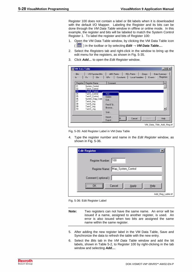
5-28 VisualMotion Programming VisualMotion 9 Application Manual
DOK-VISMOT-VM*-09VRS**-AW02-EN-P
Register 100 does not contain a label or Bit labels when it is downloadedwith the default I/O Mapper. Labeling the Register and its bits can bedone through the VM Data Table window in offline or online mode. In thisexample, the register and bits will be labeled to match the System ControlRegister 1. To label the register and bits of Register 100:
1. Open the VM Data Table window, by clicking the VM Data Table icon
( ) in the toolbar or by selecting Edit ⇒ VM Data Table….
2. Select the Registers tab and right-click in the window to bring up theedit menu for the registers, as shown in Fig. 5-35.
3. Click Add… to open the Edit Register window.
VM_Data_Tble_Add_Reg.tif
Fig. 5-35: Add Register Label in VM Data Table
4. Type the register number and name in the Edit Register window, asshown in Fig. 5-36.
Add_Reg_Lable.tif
Fig. 5-36: Edit Register Label
Note: Two registers can not have the same name. An error will beissued if a name, assigned to another register, is used. Anerror is also issued when two bits are assigned the samename within the same register.
5. After adding the new register label in the VM Data Table, Save andSynchronize the data to refresh the table with the new entry.
6. Select the Bits tab in the VM Data Table window and add the bitlabels, shown in Table 5-2, to Register 100 by right-clicking in the tabwindow and selecting Add….

VisualMotion 9 Application Manual VisualMotion Programming 5-29
DOK-VISMOT-VM*-09VRS**-AW02-EN-P
Bit Label State
07 Emergency_Stop 0 to 1
01 Parameter_Mode 1 to 0
05 Clear_Errors 0 to 1
02 Mode_Auto_Manual 0 to 1
03 Task_Stop 0 to 1
04 Taks_Start 0 to 1
Table 5-2: Bit Labels and States
7. Enter Register number 100 and the bit number and name for each bitin the Add Bit window, see Fig. 5-37.
Add_Reg_Bit.tif
Fig. 5-37: Adding Custom Register Bit Labels
8. After adding the new bit labels in the VM Data Table, Save andSynchronize the data to refresh the table with the new entries.
9. With the icon program online, select Data ⇒ Registers from theVisualMotion Toolkit menu.
VisualMotion registers can be displayed in Binary (01), Hexadecimal (0x),or Decimal (12) format. Depending on the format selected, the bits for aregister can either be manipulated in the Data Editor window or in the EditRegister window, which is displayed when Binary format is selected. Theformat can be selected in the Data Editor window.

5-30 VisualMotion Programming VisualMotion 9 Application Manual
DOK-VISMOT-VM*-09VRS**-AW02-EN-P
Registers_Format.tif
Fig. 5-38: Binary Format of Bits
10. Scroll down to register 100 and double-click it to open.
11. Change the state of the following bits in the order they are listed inTable 5-2, beginning with Bit 07, to activate the program.
When the program is running, the bit states will appear in the EditRegister 100 window, as shown in Fig. 5-40.
Active_Program.tif
Fig. 5-39: Bit Stat for Running Program
The data displayed in the Registers, Project window will indicate theprogram is running by the bits set high in register 100, the registermapped to program operation bits. In Fig. 5-40 the last bit of register 100is set to one, indicating that the system is in Parameter Mode.

VisualMotion 9 Application Manual VisualMotion Programming 5-31
DOK-VISMOT-VM*-09VRS**-AW02-EN-P
Register_Bit_High.tif
Fig. 5-40: Bit State in Register Data Display
Note: If variables were added to the sample program, be sure toassign them a value before starting the program.
Note: If the program has been started prior to adding values to thevariables, the program will not run because all variable valuesare initially zero. Stop the program by changing the state ofbits 3 and 4 from 1 to 0. Once values have been added,reinitialize the program by changing the state of bits 3 and 4back to 1.
To view which program icon is being processed within VisualMotionToolkit, select Diagnostics ⇒ Show Program Flow or press F7 on thekeyboard to turn the feature on or off. Program flow begins in theinitialization task and proceeds through the tasks and subroutines in theorder in which they are to be executed, highlighting the icons when theprogram reaches them in the program flow.

5-32 VisualMotion Programming VisualMotion 9 Application Manual
DOK-VISMOT-VM*-09VRS**-AW02-EN-P
Program_Flow.tif
Fig. 5-41: Show Program Flow
Changing the state of any one of the following bits in Register 100 willstop the program from running.
Bit Label
01 Param_Mode
02 Mode_Auto_Manual
03 Task_Stop
07 Emergency-Stop
09 Finish_VM_Program
If the program was stopped using bit 100-7, Emergency Stop, or from anerror, bit 100-5 Clear_Errors must be toggled from 1 to 0 to 1 beforerunning again. To run the program again, toggle bit 100-4 Task Startfrom 1 to 0 to 1.
Note: In order to start the program from the very beginning, toggle bit100-2, Mode_Auto_Manual, from 0 to 1 prior to toggling theTask_Start bit.
Saving a ProjectIcon programs are saved in the project folder on the computer. When aproject goes online, the icon program is automatically saved to the projectfolder on the computer. To save an icon program when offline, use theSave Program option in the VisualMotion File menu..

VisualMotion 9 Application Manual VisualMotion Programming 5-33
DOK-VISMOT-VM*-09VRS**-AW02-EN-P
Opening Existing Icon ProgramsIcon programs created in VisualMotion 7 and VisualMotion 8 can beopened in those versions or in VisualMotion 9 and downloaded to GPP9firmware, but the following issues must be considered:
• A VisualMotion 7 or 8 program that has been downloaded to GPP9firmware can not be reopened in the earlier version of VisualMotionsoftware.
• Some icons available in previous versions of VisualMotion are notavailable in VisualMotion 9. If a VisualMotion 7 or 8 icon programcontains an icon that does not exist in VisualMotion 9, the icon willappear in the program after it has been opened in VisulaMotion 9, butit must be removed if additional programming is required.
• An icon program created in VisualMotion 9 can not be downloaded tofirmware versions earlier than GPP9.
To open an existing icon program that was created in an earlier version ofVisualMotion software in VisualMotion 9, select the program from the listdisplayed in the window or double-click the Browse Existing files item inthe field to bring up the Open window. A warning is issued when aprogram created in an earlier version of VisualMotion is opened. Theprogram will open in VisualMotion 9 in Service mode.
Prgrm_Version_Message.tif
Fig. 5-42: VisualMotion Message
This completes the sample program illustration. Additional features inVisualMotion for saving, importing/exporting, and archiving projects arediscussed in the VisualMotion 9 Functional Description manual.Advanced features for icon programming are discussed in the followingsection.

5-34 VisualMotion Programming VisualMotion 9 Application Manual
DOK-VISMOT-VM*-09VRS**-AW02-EN-P
5.5 Advanced Programming with Events
An advanced method of program construction can be used where eventsare added to the icon program to control the execution of a task withgreater accuracy. Events are special subroutines that run only if theyhave been armed and specific conditions have been met. An eventconsists of:
• Trigger – is the information used to arm an event and contains thefollowing:
• Event number – this indicates the order that an event is added tothe VM Data Table, but has no significance outside the data table.
• Event name – this is a user defined label for the event trigger in thedata table.
• Event argument – the value or condition that must be met for theevent function to run.
• Event type – this is one of the following: coordinated motion, single-axis motion, Repeating Timer, Rotary, Probe, or I/O.
• Event function name – the name for the special subroutine calledby the trigger.
• Event Function – The special subroutine that runs when the triggercondition is met.
VisualMotion Toolkit offers the flexibility of adding events in more thanone way to an icon program. The VM Data Table information for eventtriggers can be created prior to the icon program. The Events tab in theVM Data Table window displays all the data associated with each eventtrigger in the project and allows data to be edited, deleted, and created.
VM_Data_Table_Events.tif
Fig. 5-43: VM Data Table Events Tab
Event triggers can also be created through the event related icons in theicon program, including the event, move, circle, and path icons. The VMData Table is accessed with the browse button in each of these iconsetup windows. The icons used to arm an event in an icon programdepend on the event type. This chapter discusses the various types ofevents and how to add them to the icon program.

VisualMotion 9 Application Manual VisualMotion Programming 5-35
DOK-VISMOT-VM*-09VRS**-AW02-EN-P
Note: A Calc icon can also be used to create an event trigger in theicon program. For more information about the argumentsused in the Calc icon for events, refer to the VisualMotion 8(GPP) Multi-Axis Motion Control Application Manual, Rev 02.
More than one event arming icon can be configured with the same eventtrigger, as illustrated in Fig. 5-44. It is also possible to have more thanone event trigger call an event function. The event function is notdependent on the type of event trigger; any type of event trigger can callan event function. The event type selected in the Event Arm/Disarmwindow must match the trigger event type. For example, rotary eventarming icon must be configured with a rotary event trigger.
Arm Rotary 1Arm Timer 2Arm Rotary 2Arm Move 4Arm Rotary 3Arm Move 6Arm Rotary 8Arm Move 7…
Rotary Event TriggerTimer Event TriggerMove Event TriggerMove Event TriggerMove Event TriggerTimer Event TriggerMove Event TriggerMove Event Trigger…
Event Function 1Event Function 2Event Function 3Event Function 4Event Function 5Event Function 6Event Function 7Event Function 8…
Event Arm/DisarmIcon Selection
Event Trigger Types Event Functions
Fig. 5-44: Event Arming, Trigger, and Function Relationship
Event functions are added by selecting Edit ⇒ VM Data or Insert⇒ Event Function… from the VisualMotion main menu. An eventfunction can also be added by right-clicking the Event Functions folder inthe Project Navigator tab.

5-36 VisualMotion Programming VisualMotion 9 Application Manual
DOK-VISMOT-VM*-09VRS**-AW02-EN-P
Add_Event_Function.tif
Fig. 5-45: Project Navigator
This opens the Event Function Control Block window where the eventname is entered. After the event function name is entered, a new iconprogramming workspace opens with a Start and Finish icon in place.
E_function_block.tif
Fig. 5-46: Event Function Control Block window
Create the event function that will run when the condition in the iconprogram is true.
Note: Icon instructions that require a long time to process, such asthe Wait, Branch, and Parameter Transfer icon instructions,should be avoided in event programs.

VisualMotion 9 Application Manual VisualMotion Programming 5-37
DOK-VISMOT-VM*-09VRS**-AW02-EN-P
Online Event ProgrammingNew events can not be added to the icon program while online mode, butexisting events can be edited. The event type, event function name, andevent argument value can be edited while the icon program is online. Toedit an event online:
1. Select Data ⇒ Events… to open the Events, Project window.
2. Double-click the event to open the Edit Event Values window.
Online_Events_Edit.tif
Fig. 5-47: Edit Event Values Window
Note: When making changes to the event type while online, thetrigger event type must always match the event type selectedin the icon program.
Note: The VM Data Table can not be used to make online changesto events.
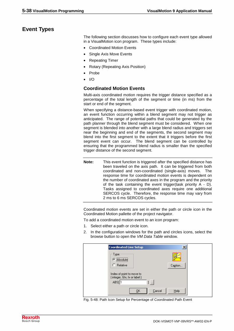
5-38 VisualMotion Programming VisualMotion 9 Application Manual
DOK-VISMOT-VM*-09VRS**-AW02-EN-P
Event TypesThe following section discusses how to configure each event type allowedin a VisualMotion icon program. These types include:
• Coordinated Motion Events
• Single Axis Move Events
• Repeating Timer
• Rotary (Repeating Axis Position)
• Probe
• I/O
Coordinated Motion EventsMulti-axis coordinated motion requires the trigger distance specified as apercentage of the total length of the segment or time (in ms) from thestart or end of the segment.
When specifying a distance-based event trigger with coordinated motion,an event function occurring within a blend segment may not trigger asanticipated. The range of potential paths that could be generated by thepath planner through the blend segment must be considered. When onesegment is blended into another with a large blend radius and triggers setnear the beginning and end of the segments, the second segment mayblend into the first segment to the extent that it triggers before the firstsegment event can occur. The blend segment can be controlled byensuring that the programmed blend radius is smaller than the specifiedtrigger distance of the second segment.
Note: This event function is triggered after the specified distance hasbeen traveled on the axis path. It can be triggered from bothcoordinated and non-coordinated (single-axis) moves. Theresponse time for coordinated motion events is dependent onthe number of coordinated axes in the program and the priorityof the task containing the event trigger(task priority A - D).Tasks assigned to coordinated axes require one additionalSERCOS cycle. Therefore, the response time may vary from2 ms to 6 ms SERCOS cycles.
Coordinated motion events are set in either the path or circle icon in theCoordinated Motion pallette of the project navigator.
To add a coordinated motion event to an icon program:
1. Select either a path or circle icon.
2. In the configuration windows for the path and circles icons, select thebrowse button to open the VM Data Table window.
Fig. 5-48: Path Icon Setup for Percentage of Coordinated Path Event

VisualMotion 9 Application Manual VisualMotion Programming 5-39
DOK-VISMOT-VM*-09VRS**-AW02-EN-P
3. In the ABS Points tab, right-click in the empty table and select Add toopen the Add ABS Point window.
Add_ABS_Point.tif
Fig. 5-49: Add ABS Point Window
4. Click a check box in the Enable Events field to activate the browsebutton.
5. Click the browse button to open the VM Data Table window with theEvents tab displayed.
6. In the Events tab, click Add to open the Add Event window.
The Event Type field is inactive with the type selected by default. Theevent types selected by default is determined by the icon setup window, inthis case the Coordinated Line Setup window.

5-40 VisualMotion Programming VisualMotion 9 Application Manual
DOK-VISMOT-VM*-09VRS**-AW02-EN-P
Prcnt_Coord_Pth.tif
Fig. 5-50: Add Event Window
7. Enter a value for the event argument and select the coordinatedmotion event type.
8. Select the event function from the drop-down menu or create a newevent function by clicking the New Function… button.
Note: The event function entered will not appear in VisualMotionToolkit outside of this window. You will have to recall frommemory the title used in this window when creating the actualevent, if you have not already created the event. If the eventwas created before assigning the event function, the title willappear in the Event Function drop-down menu.
The event type and data are set in the Add Event window.
Note: The Event Type (Coordinated Motion) is selected by default inthe Add Event window and matches the Event Type selectedin the Event Arm/Disarm window.
Single Axis Motion EventsFor single axis non-coordinated motion, an event function can betriggered at a set distance from the start or before the end of a move, byassigning a value to the motion path. The event function to be executedis specified with the event function name in the Events for this move fieldof the Single Axis Move Setup window.

VisualMotion 9 Application Manual VisualMotion Programming 5-41
DOK-VISMOT-VM*-09VRS**-AW02-EN-P
Note: Single axis, non-coordinated, motion icons use the internalpositioning intelligence of Bosch Rexroth's digital drives.Because the rate profile for single axis motion is developedwithin the drive, the time method of triggering an event relatedto motion is not supported.
To add a single axis event to an icon program:
1. Place a Move icon in the your project.
2. Select the axis in which you want the event to occur, in the SingleAxis Move Setup window.
Single_Axis_Distance.tif
Fig. 5-51: Single Axis Distance Event Setup
3. Select the distance in the move for the argument.
4. Enter the events for the move by typing the number of the event or byselecting the event from the Events tab in the VM Data Table window.

5-42 VisualMotion Programming VisualMotion 9 Application Manual
DOK-VISMOT-VM*-09VRS**-AW02-EN-P
Add_Event_Single_Axis.tif
Fig. 5-52: Add Event Window
Repeating Timer EventThe repeating timer event is triggered by an internal clock that runsindependently of the event’s associated task. The argument for the eventis a value which represents the time interval between each triggering ofthe event. Because the event automatically rearms itself, it will runcontinuously until it is disarmed.
When using a repeating timer event in your project, it is important torestrict the type of icons you place in the event function as the eventpreempts all user tasks. Task response time and execution can beadversely affected if the event function requires a long time to process.Icons to avoid or use with caution in an event function include, Parametertransfer, Wait, and Branch (looping).
To add a repeating timer event to a project:
1. Place an Event icon in the icon program to arm the event.
2. In the Event Arm/Disarm window, select Arm Event for the EventAction and Repeating Timer for the Event Type.

VisualMotion 9 Application Manual VisualMotion Programming 5-43
DOK-VISMOT-VM*-09VRS**-AW02-EN-P
Repeating_Timer_Event.tif
Fig. 5-53: Event Arm/Disarm Window
3. Type an event name in the Event Trigger field, select the eventname from the Events tab in the VM Data Table window, or create anew event name by selecting Add to open the Add Event window.
To disarm the repeating timer event, place a second Event icon in theprogram and select Disarm Event for the event action.
Rotary (Repeating Axis Position) EventRotary events are triggered each time the axis encounters an absoluteposition. The axis motion type can be single-axis, ELS, ratio, or velocitymode and configured for modulo or non-modulo positioning.
The event function will be triggered each time the axis reaches theposition (from either direction) set in the argument. Because rotarymotion uses the shortest path to reach the next specified position, verifythat the axis will travel through the position specified in the argument. Ifthe event is not disarmed with a second Event icon placed in the sametask, it will continue to run even after its associated task has ended.
Note: Rotary events cannot be assigned to an axis with single axisdistance based events.
To add a Rotary event to a project:
1. Place an Event icon in your icon program.
2. Select Arm Event for the Event Action.

5-44 VisualMotion Programming VisualMotion 9 Application Manual
DOK-VISMOT-VM*-09VRS**-AW02-EN-P
Rotary_Event.tif
Fig. 5-54: Event Arm/Disarm Window
3. Select Rotary for the Event Type.
4. Type an event name in the Event Trigger field, select the eventname from the Events tab in the VM Data Table window, or create anew event name by selecting Add to open the Add Event window.
5. Select a signal source, depending on whether the event function willbe triggered by a single axis, ELS group, or ELS master, position.
Probe EventVisualMotion supports SERCOS probe functionality and real-time bitsalong with the event system to allow icon programs to perform registrationfunctions. The DIAX04 and ECODRIVE03 digital drives provide twoprobe inputs that can be used for capturing the feedback position.
Note: Only the DIAX04 digital drive is capable of transmitting probefeedback from two probes simultaneously through theSERCOS cyclic data telegram. The ECODRIVE03 is limitedby its smaller bit capability to a single probe. To send asecond probe signal with the ECODRIVE03, it is necessary tore-initiate the icon program.

VisualMotion 9 Application Manual VisualMotion Programming 5-45
DOK-VISMOT-VM*-09VRS**-AW02-EN-P
The inputs are physically wired to each drive according to Fig. 5-55.
������
���
���
���
���
���
���
���
��
���
��
� �
��
�
��
��
�
� �
��
�
��
������
�
���
!
��
��
��""�
#� ��
����
������
��
������������������
��� ���������!����� ���������!��
Inputs:0V ext
1
3456789
1011
X3
12131415161718
2
24V
delete error
warning
error
analog E2+
analog E1+analog E1-
0V
analog E2-
0Vanalog A2
UD
E-STOP
Limit+Limit-
Ref
Cam1 / MessT1Cam2 / MessT2
analog A1
length l
ECODRIVE03 with SERCOS Interface
DIAX04 using the DSS2.1 SERCOSInterface Card
probe_inputs.EPS/AP5092F1.EPS
Fig. 5-55: Connecting the Probe Inputs
The probe inputs are scanned every 1 µs. Upon either a positive ornegative transition of a probe input, the drive captures and places theposition into the cyclic data telegram.
Typically, probes are used to detect registration marks on material. Bycontrolling when the probe is armed, other printing on the material can befiltered out. When the position is captured, the drive signals the controlwith a real time bit in the SERCOS cyclic data telegram. When thecontrol detects a change in the real time bit, it can execute an optionalevent function.
Note: It is also important that the value being read in the feedbackevent matches the parameter in the amplifier telegram (AT). Iffeedback is requested from a probe and its associatedparameter is not in the AT, the service channel is used totransmit the data.
To add a Probe event to an icon program:
1. Place an Axis icon in the Initialization task of your project.
2. Select the Motion Type for the Axis.

5-46 VisualMotion Programming VisualMotion 9 Application Manual
DOK-VISMOT-VM*-09VRS**-AW02-EN-P
Note: Probes can be configured for the following motion typesavailable in the drop-down menu of the Task Axes Setupwindow:
• Single Axis
• Coordinated
• Velocity
• Ratioed Axis
• Torque Mode
• Torque following Mode
3. Click Add… to open the Single Axis Setup window.
Probe_Config.tif
Fig. 5-56: Configure Probe Window
4. Click Configure Probe(s)… to open the Configure Probe window.
The following table lists the four probe triggers and their associatedSERCOS and Control parameters:
Probe Trigger SERCOS Parameter Control Parameter
Probe 1, 0->1 S-0-0130 A-0-171
Probe 1, 1->0 S-0-0131 A-0-172
Probe 2, 0->1 S-0-0132 A-0-173
Probe 2, 1->0 S-0-0133 A-0-174
5. Select the probes that will be associated with each event trigger in theConfigure Probe window.

VisualMotion 9 Application Manual VisualMotion Programming 5-47
DOK-VISMOT-VM*-09VRS**-AW02-EN-P
6. In Task A of the Icon program, place an Event icon in program flow.
Probe_Event.tif
Fig. 5-57: Event Arm/Disarm Window
7. Select Probe for Event Type.
8. Type the event trigger name or select it from the VM Data Table.
9. Select the probe trigger for the event.
10. Select the same Axis for the event that was set in the Axes icon inthe Initialization Task.
Note: Configure the probes in the drives using DriveTop. Refer todrive documentation for additional information on configuringdrives.
I/O EventsEvents can be triggered through an I/O register or bit. There are fourtypes of I/O Events:
• Task Input Transition
• I/O Register Event
• PPC-R Input Event (0->1)
• PPC-R Input Event (1->0)
Bit 9 of each Task Control Register (#002 -#005) is reserved as an eventinterrupt input for the task. Every low-to-high transition of this input cantrigger an event function. Following a high-to-low transition of the input,the event is rearmed automatically. To Disarm the event, an additionalevent icon in the program flow is necessary to disarm the event.
Task Input Transition Event
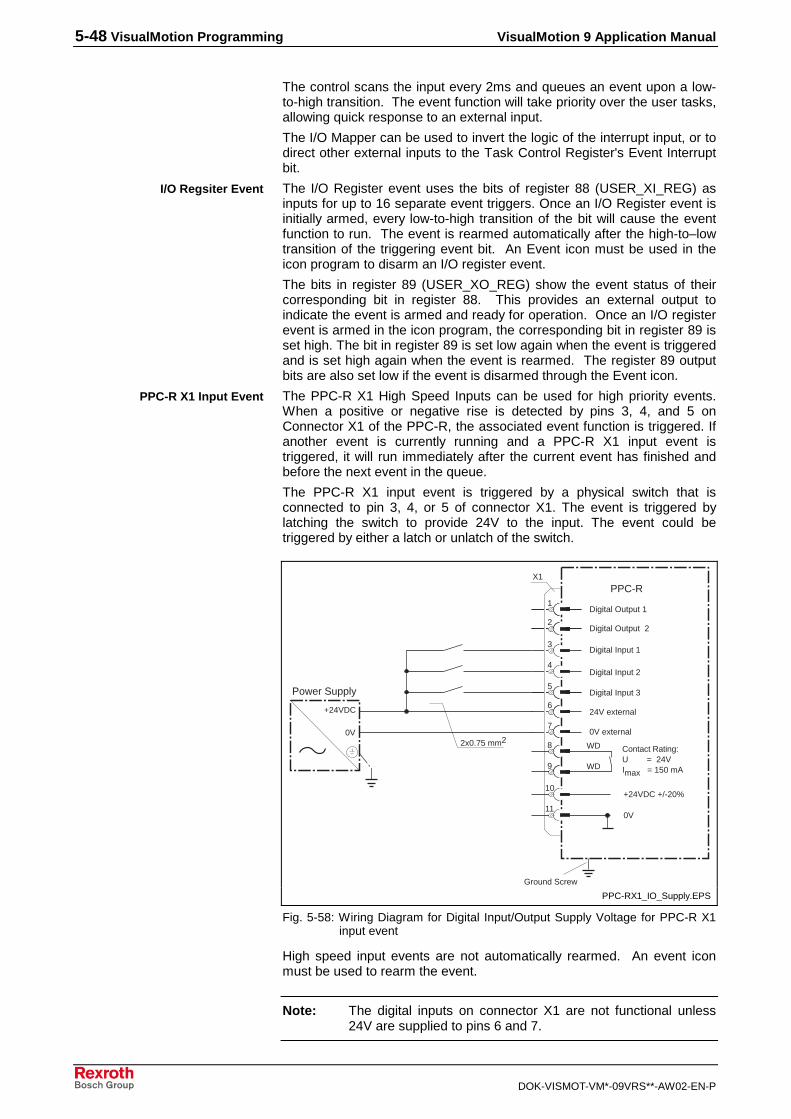
5-48 VisualMotion Programming VisualMotion 9 Application Manual
DOK-VISMOT-VM*-09VRS**-AW02-EN-P
The control scans the input every 2ms and queues an event upon a low-to-high transition. The event function will take priority over the user tasks,allowing quick response to an external input.
The I/O Mapper can be used to invert the logic of the interrupt input, or todirect other external inputs to the Task Control Register's Event Interruptbit.
The I/O Register event uses the bits of register 88 (USER_XI_REG) asinputs for up to 16 separate event triggers. Once an I/O Register event isinitially armed, every low-to-high transition of the bit will cause the eventfunction to run. The event is rearmed automatically after the high-to–lowtransition of the triggering event bit. An Event icon must be used in theicon program to disarm an I/O register event.
The bits in register 89 (USER_XO_REG) show the event status of theircorresponding bit in register 88. This provides an external output toindicate the event is armed and ready for operation. Once an I/O registerevent is armed in the icon program, the corresponding bit in register 89 isset high. The bit in register 89 is set low again when the event is triggeredand is set high again when the event is rearmed. The register 89 outputbits are also set low if the event is disarmed through the Event icon.
The PPC-R X1 High Speed Inputs can be used for high priority events.When a positive or negative rise is detected by pins 3, 4, and 5 onConnector X1 of the PPC-R, the associated event function is triggered. Ifanother event is currently running and a PPC-R X1 input event istriggered, it will run immediately after the current event has finished andbefore the next event in the queue.
The PPC-R X1 input event is triggered by a physical switch that isconnected to pin 3, 4, or 5 of connector X1. The event is triggered bylatching the switch to provide 24V to the input. The event could betriggered by either a latch or unlatch of the switch.
9
8
7
6
5
1
2
10
11
3
4
0V
X1
WD
+24VDC +/-20%
WD
+24VDC
Contact Rating:U = 24VImax = 150 mA
PPC-R
Power Supply
0V
2x0.75 mm20V external
24V external
Digital Input 3
Digital Input 2
Digital Input 1
Digital Output 2
Digital Output 1
Ground Screw
PPC-RX1_IO_Supply.EPS
Fig. 5-58: Wiring Diagram for Digital Input/Output Supply Voltage for PPC-R X1input event
High speed input events are not automatically rearmed. An event iconmust be used to rearm the event.
Note: The digital inputs on connector X1 are not functional unless24V are supplied to pins 6 and 7.
I/O Regsiter Event
PPC-R X1 Input Event

VisualMotion 9 Application Manual VisualMotion Programming 5-49
DOK-VISMOT-VM*-09VRS**-AW02-EN-P
I/O Events are added through the Event icon in VisualMotion. To add anI/O Event to a project:
1. Place an Event icon in the task where the event will occur in your iconprogram.
2. In the Event Arm/Disarm window, select Arm Event.
3. Select I/O for the Event Type.
4. Type the name of the event function or select or create one byselecting the VM Data Table button.
5. In the VM Data window, select the Events tab and select an event orclick the Add button to create a new event.
6. In the Add Event window, enter the event number and name.
7. Select the I/O Event Type and enter the event function name orcreate a new one with the New Function… button.
Add_Event_IO.tif
Fig. 5-59: Add Event Window
Event ProcessingIf more than one event is used in an application, the events are prioritizedaccording to the following designation:
Highest Priority 1 - Path Planner and single axis events
Priority 2 - Event from Task A
Priority 3 - Event from Task B
Priority 4 - Event from Task C
Priority 5 - Event from Task D
Priority 6 - Timer Task (repeating events)
Lowest Priority 7 - User Tasks A, B, C, D and BTC06
Adding an I/O Event

5-50 VisualMotion Programming VisualMotion 9 Application Manual
DOK-VISMOT-VM*-09VRS**-AW02-EN-P
The following conditions should be considered when creating aVisualMotion project with events:
• Events interrupt user tasks
• Events (except the repeating timer event) are assigned to a user task
• Each user task has a separate event queue, which can store up to 25events
• The repeating timer event queue is separate from user task queuesand can store up to 16 events
Note: An event queue (stack) is a storage area where events areplaced as they are triggered. The events are accumulated inthe queue and are activated in the order in which they arereceived. Once an event has been executed, it is cleared fromthe queue and the remaining events move up in the queue. Ifthe maximum number of event queues is exceeded, a StackOverflow error will be issued by VisualMotion.
• A higher priority event interrupts a lower priority event. For example,events associated with Task A will interrupt execution of eventsassociated with Tasks B, C, & D. Events associated with Task B willinterrupt events associated with Tasks C & D, and so on.
• The queue handles events with the same priority in a First In First Out(FIFO) order.
The PPC-R X1 input events are considered “fast input events” and willalways be placed at the top of the FIFO queue.

VisualMotion 9 Application Manual VisualMotion Programming 5-51
DOK-VISMOT-VM*-09VRS**-AW02-EN-P
The following table contains a summary of the parameters for each eventtype described in detail in the previous section.
Event Type Examples ArmMechanism
AutoRearm
MaximumNumber
Priority*
CoordinatedMotion
• Start a movefrom another axis
• Control a gluegun
No 4 events per movesegment
1 to 4, based on whichtask the axis isassigned
Single AxisMotion
• Start a movefrom another axis
• Control a gluegun
No 4 events per singleaxis move
1 to 4 based on whichtask the axis isassigned
RepeatingTimer
• Switch a pumpon every hour
• Calculatestatistics everyminute
Yes 16 absolute 5 = lowest
RotaryRepeating Axis
• Control a valve
• Change the H-Factor
• Start a movefrom another axis
Yes 4 for each axis,group, or master
1 to 4 based on whichtask the single axis isassigned
Probe • Latch motorposition of drivefor registrationfunction
• Detect productposition on a belt
No 2 per drive 1 to 4 based on whichtask the axis isassigned
I/O Register • Move SERVO toa predefinedposition afteropening a door
Yes 16 absolute 1 for Task A
Task InputTransition
• Start acalculation
• Move SERVO toa predefinedposition afteropening a door
Yes 1 per task 1 for Task A, 2 for TaskB, 3 for Task C, and 4for Task D
PPC-R X1 Input • Time criticalmeasurements
• Latch virtualmaster position
No 3 absolute 1 for Task A
Table 5-3: Summary of Event Parameters
* Priority Levels: Task A = 1 (Highest)
Task B = 2
Task C = 3
Task D = 4
Repeating Timer = 5 (Lowest)
Summary of Event Types

5-52 VisualMotion Programming VisualMotion 9 Application Manual
DOK-VISMOT-VM*-09VRS**-AW02-EN-P
Runtime SetupThe Runtime setup allows you to associate a new event argument orevent function to an existing event. The Runtime setup values for anevent will overwrite the values for that same event in the VM data table.
Runtime changes can be set in the Runtime Setup field in the Event andMove icons.
Note: The functionality of the Runtime Setup was accomplishedusing the Calc icon in earlier versions of VisualMotion. TheCalc icon can still be used to change event values inVisualMotion 9 as in previous versions of VisualMotion. Referto the events topic in VisualMotion online help for informationabout configuring the Calc icon for and event.
The Runtime Setup field in the Event and Move icons has a Set… buttonwhich opens the Runtime Event Configuration window.
Runtime_Setup.tif
Fig. 5-60: Runtime Event Configuration Window
Note: If a disarm function is used for an event, neither the argumentor event function can be changed in runtime. In the RuntimeEvent Configuration window, the event function should bedisabled by removing the check in the Enable check box.
A list of all the events in a project can be viewed by selecting View⇒ Event Function…in the VisualMotion Toolkit main menu.

VisualMotion 9 Application Manual VisualMotion Programming 5-53
DOK-VISMOT-VM*-09VRS**-AW02-EN-P
Event_Function.tif
Fig. 5-61: Event Functions Window
In the Runtime Event Configuration window, the Enable checkbox mustbe selected to enable the Argument and Event Function fields.
Runtime_Event_Config.tif
Fig. 5-62: Runtime Event Configuration Window
The checkbox can also be used to deactivate either setting so that theprogram will continue to use the original settings in the event trigger.
5.6 Service Mode
Tools launched from the icon editor without a project loaded will default toservice mode. This mode provides access to the control when no projectdata is available. All of the data on the control can be viewed andchanged, without the project being open. Backup and restore operationsare also possible in this mode.
To open VisualMotion Toolkit in service mode:
1. Launch VisualMotion Toolkit.
2. In the project selection window, select View and edit control data in“Service” mode.

5-54 VisualMotion Programming VisualMotion 9 Application Manual
DOK-VISMOT-VM*-09VRS**-AW02-EN-P
Open_Service_Mode.tif
Fig. 5-63: View VisualMotion in Service Mode
VisualMotion Toolkit will open with all menus available except Edit, View,and Insert. The menus will display the values of the last program thatwas downloaded to the control. The icon workspace will be absent fromthe window because it is not possible to interact with a project while in thismode.
VM_Toolkit_Service_Mode.tif
Fig. 5-64: VisualMotion Toolkit in Service Mode

VisualMotion 9 Application Manual Electronic Line Shafting (ELS) 6-1
DOK-VISMOT-VM*-09VRS**-AW02-EN-P
6 Electronic Line Shafting (ELS)Electronic Line Shafting (ELS) is a robust synchronization system thatprecisely controls motion using electronic gearing and cams. The ELSsystem has the following components that are connected throughadaptable interfaces:
• Command Sources
• Signal Router
• Axis Groups
• Individual Axes
The interfaces can switch between the defined signal path to meet thedynamics of the application, see Fig. 6-1.
VisualMotion GPP software and firmware allow more than one activemaster at a time to support ELS functionality. Electronically synchronizedaxes can be combined to form ELS Groups. Active masters can control amaximum of eight ELS Groups. Every ELS Group will follow its selectedmaster.
6.1 ELS Overview
GPP supports six system masters in any combination up to a maximumof the following types:
• 2 Virtual Masters
• 6 Real Masters
• 6 ELS Group Masters
• 6 Link Ring Master IN
• 1 Link Ring Master OUT
Position commands originate from either a Virtual Master in the control ora Real Master generated by a sensor on the motor. The Virtual Master orReal Master signal are assigned a number in the ELS System connectionbox and can be modified before it is sent to an ELS Group. An outputsignal from an ELS group can be sent to another ELS Group after beingassigned a new ELS System Master number. The example configurationin Fig. 6-1 shows the signal flow through a system with 2 Virtual Masters,2 Real Masters, 1 ELS Group Master and 4 ELS Groups. Five ELSSystem Master numbers are assigned in the connection box.

6-2 Electronic Line Shafting (ELS) VisualMotion 9 Application Manual
DOK-VISMOT-VM*-09VRS**-AW02-EN-P
virtualmaster
1
virtualmaster
2
ELSgroup
ELSgroup
ELSgroup
Motion Control
axes 1 2 3 4 5 6 7 8 9 10 11
real master axes 1 2 3
1 2 3 4 5 6
link master position(send to link ring)
ELSgroupmaster
connection box
ELS groupmaster
axes 0(for ratio)
link master position(s)(received from link ring)
CommandSources
SignalRouter
AxisGroups
IndividualAxes
Fig. 6-1: Multiple Master Configuration Example
Multiple master functionality in VisualMotion includes 5 types of mastersand one group:
Virtual MasterA Virtual master is a component that generates a command streambased on its input settings. VisualMotion provides two independentVirtual masters that are used to drive a group of axes or programmablelimit switches. A Virtual Master has two primary modes of operations:
• Velocity Mode – continuous running
• Position Mode – indexing, jogging
Real MasterA Real Master is either a primary motor (positive feedback) or secondaryencoder (Aux) signal from a drive. Each drive in the system canpotentially provide two Real Masters. The raw position value of the RealMaster can be filtered and geared by an M/N ratio.
ELS Group MasterAn ELS Group Master is the output position of an ELS Group used as aninput master signal, geared by an M/N ratio, to a different ELS Group.
ELS System MasterVirtual Masters, Real Masters and ELS Group Masters can be combinedand assigned to one of 6 ELS System Masters. The master signal fromeach active system master is conditioned (e.g., geared or filtered) andmade available for controlling groups of axes.

VisualMotion 9 Application Manual Electronic Line Shafting (ELS) 6-3
DOK-VISMOT-VM*-09VRS**-AW02-EN-P
Link Ring MasterA link Ring Master is an external PPC-R configured as master, which canhave up to 31 PPC-Rs configured as Link Ring Slave controls interfacingwith it in a fiber optic ring, called a Link Ring.
ELS GroupAn ELS Group is defined as a set of slave axes (40 axes maximum) thatfollow the position command signal from one of the 6 System Masters.By using ELS Groups, slave axes are combined, according to theirfunction, in groups that control each machine section as an independentprocess. During operation, an ELS Group can be switched betweenmaster signals. Any changes to ELS Group parameters are immediatelyavailable to all axes assigned to that group, so that precisesynchronization of the machine section is maintained.
6.2 Assigning Variable and Register Labels
VisualMotion provides 1024 registers for controlling and monitoring theproject. During configuration of the Virtual Masters, ELS Groups, andSystem Masters, their associated control and status registers must beassigned to a free register. The system has default address rangesdefined for the various components, which are automatically indexed aseach is created. If you are new to the system, it is recommended that youuse the default addresses where possible to simplify the label assignmentprocedure.
Default labels and comments can be added using the Assign VariableLabels… button in the icon configuration windows for ELS SystemMaster, ELS Group, and Virtual Master icons. The Variable Labelswindow displays the Data object, Label, and Comment fields forvariables, registers and bits. The window has two buttons that allow youto add the default labels for the variables, registers, and bits:
• Add Default Labels - This button adds all default labels for the datatype selected.
• Add All Default Labels – This button adds all default labels for allthree data types.
Fig. 6-2 shows an example of adding default labels in the dialog window.
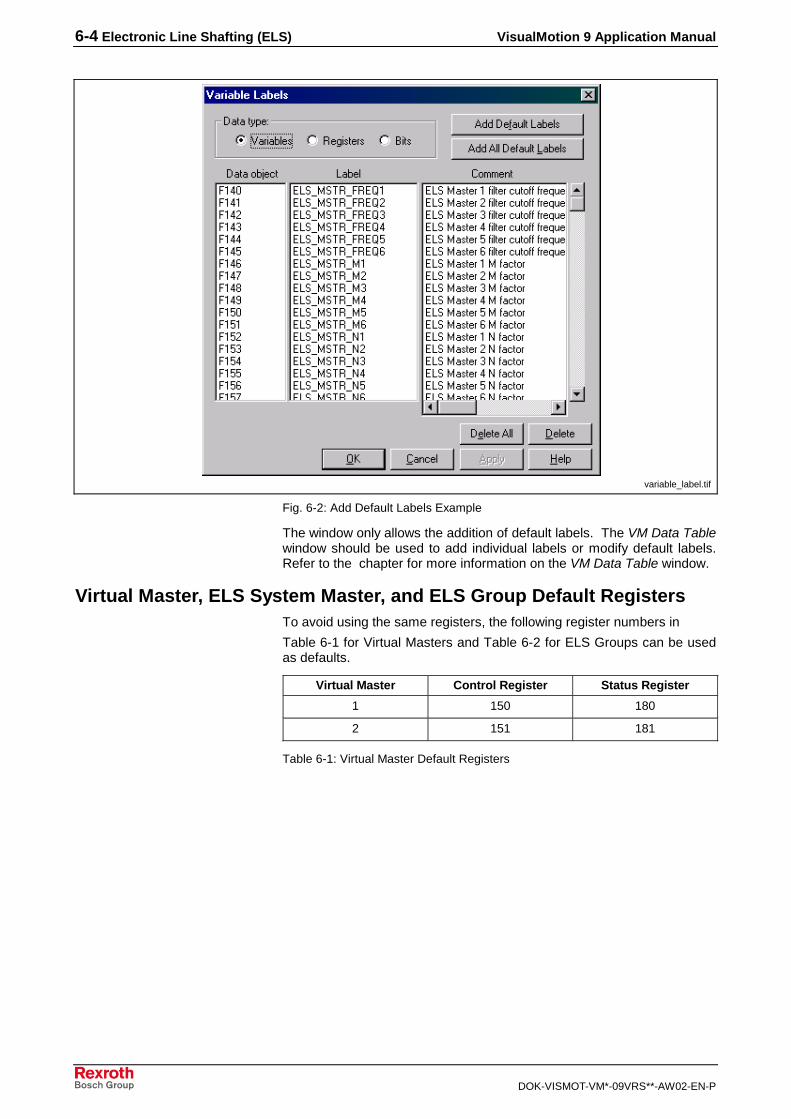
6-4 Electronic Line Shafting (ELS) VisualMotion 9 Application Manual
DOK-VISMOT-VM*-09VRS**-AW02-EN-P
variable_label.tif
Fig. 6-2: Add Default Labels Example
The window only allows the addition of default labels. The VM Data Tablewindow should be used to add individual labels or modify default labels.Refer to the chapter for more information on the VM Data Table window.
Virtual Master, ELS System Master, and ELS Group Default RegistersTo avoid using the same registers, the following register numbers in
Table 6-1 for Virtual Masters and Table 6-2 for ELS Groups can be usedas defaults.
Virtual Master Control Register Status Register
1 150 180
2 151 181
Table 6-1: Virtual Master Default Registers

VisualMotion 9 Application Manual Electronic Line Shafting (ELS) 6-5
DOK-VISMOT-VM*-09VRS**-AW02-EN-P
ELS Group Control Register Status Register
1 152 182
2 153 183
3 154 184
4 155 185
5 156 186
6 157 187
7 158 188
8 159 189
Table 6-2: ELS Group Default Registers
ELS System Master Control Register Status Register
1-6 140 141
Table 6-3: ELS System Master Default Register
Assigning Program VariablesValues that are used by VisualMotion to run the project, such as VirtualMaster velocity or acceleration, are stored as program variables.Variables of the same type (float or integer) are typically assignedconsecutive numbers in a register to form a group or “Block” of variables.When configuring a group or master, the icon window will prompt you toenter the initial (lowest) variable number of the block, called the “start ID”.In the field of the start ID, the block size is indicated. Table 6-4 containsthe default start ID and block for each of the mentioned programvariables.
Function Number of Floats Number of Integers Float ID Block Integer ID Block
Virtual Master 1 15 2 F100-F114 I100-I101
Virtual Master 2 15 2 F120-F134 I105-I106
ELS Master Assignment 49 30 F140-F189 I110-I139
ELS Group 1 29 9 F190-F218 I140-I148
ELS Group 2 29 9 F220-F248 I150-I158
ELS Group 3 29 9 F250-F278 I160-I168
ELS Group 4 29 9 F280-F308 I170-I178
ELS Group 5 29 9 F310-F338 I180-I188
ELS Group 6 29 9 F340-F368 I190-I198
ELS Group 7 29 9 F370-F398 I200-I208
ELS Group 8 29 9 F400-F428 I210-I218
Table 6-4: Program Variable Default Start ID Blocks

6-6 Electronic Line Shafting (ELS) VisualMotion 9 Application Manual
DOK-VISMOT-VM*-09VRS**-AW02-EN-P
Virtual Master 1 & 2 Default Register LabelsThe default labels for the Virtual Master registers are shown in Table 6-5.The corresponding default bit labels are shown in Table 6-6.
Data Object Type Label (20 character limit) Comment (80 character limit)
Assigned control register number VM#_CONTROL_REG Virtual Master # control register
Assigned status register number VM#_STATUS_REG Virtual Master # status register
Table 6-5: Virtual Master Default Registers
Default LabelVirtual Master 1 & 2Control Register
Data ObjectVirtual Master 1Control Register-Bit
Data ObjectVirtual Master 2Control Register-Bit
Comment (80 character limit)Virtual Master 1 & 2 Control Register
VM#_CT_FSTOP 150-1 151-1 VM # control, 0 → 1 triggers fast stop
VM#_CT_HOME 150-2 151-2 VM # control, 0 → 1 loads home position
VM#_CT_GO 150-3 151-3 VM # control, 0=stop, 1=go
VM#_CT_VMODE 150-4 151-4 VM # control, 0=position, 1=velocity mode
VM#_CT_RELMODE 150-5 151-5 VM # control, 0=absolute, 1=relative mode
VM#_CT_RELTRIG 150-6 151-6 VM # control, 0 → 1 triggers relative mode
Default LabelVirtual Master 1 & 2Status Register
Data ObjectVirtual Master 1Control Register-Bit
Data ObjectVirtual Master 2Status Register-Bit
Comment (80 character limit)Virtual Master 1 & 2 Status Register
VM#_ST_FSTOP 241-1 242-1 VM # status, 1=fast stop active
VM#_ST_HOME 241-2 242-2 VM # status, 1=home complete
VM#_RESERVE3 241-3 242-3
VM#_ST_VMODE 241-4 242-4 VM # status, 1=velocity mode
VM#_ST_RELMODE 241-5 242-5 VM # status, 1=relative mode
VM#_RESERVE6 241-6 242-6
VM#_ST_ZEROVEL 241-7 242-7 VM # status, 1=standstill, 0=velocity
VM#_ST_INPOS 241-8 242-8 VM # status, 1=in position
Each # symbol represents an entry for the number of the Virtual Master
Table 6-6: Virtual Master 1 & 2 Default Register Bits

VisualMotion 9 Application Manual Electronic Line Shafting (ELS) 6-7
DOK-VISMOT-VM*-09VRS**-AW02-EN-P
Virtual Master 1 & 2 Default Program Variable Labels
Default LabelVirtual Master 1 & 2Program Variable
Data ObjectVirtual Master
1 & 2
Comment (80 character limit)Virtual Master 1 & 2 Program Variable
DefaultValue
Units UpdateMode
VM#_HOME_POS F100 F120 Virtual Master # home position 0 Degrees Phase 4
VM#_REL_MOVE_DIST F101 F121 Virtual Master # relative move distance 1 Degrees Phase 4
VM#_STOP_POS F102 F122 Virtual Master # stop position 0 Degrees Phase 4
VM#_CMD_ABS_POS F103 F123 Virtual Master # commanded absolute position 0 Degrees Phase 4
VM#_CMD_VEL F104 F124 Virtual Master # commanded velocity 20 RPM Phase 4
VM#_CMD_ACCEL F105 F125 Virtual Master # commanded acceleration 100 Rad/sec² Phase 4
VM#_CMD_DECEL F106 F126 Virtual Master # commanded deceleration 100 Rad/sec² Phase 4
VM#_E_STOP_DECEL F107 F127 Virtual Master # E-Stop deceleration 500 Rad/sec² Phase 2
VM#_MAX_VEL F108 F128 Virtual Master # maximum velocity 3200 RPM Phase 2
VM#_MAX_ACCEL F109 F129 Virtual Master # maximum acceleration 1000 Rad/sec² Phase 2
VM#_MAX_DECEL F110 F130 Virtual Master # maximum deceleration 1000 Rad/sec² Phase 2
VM#_JERK_ENABLE F111 F131 Virtual Master # jerk limiting enable 1 Phase 2
VM#_CUR_POS F112 F132 Virtual Master # current position 0 Degrees Phase 4
VM#_CUR_VEL F113 F133 Virtual Master # current velocity 0 RPM Phase 4
VM#_POS_WIN F114 F134 Virtual Master # shortest path window 1 Degrees Phase 2
VM#_POS_MODE I100 I105 Virtual Master # positioning mode 1.) 0 Phase 2
VM#_RESERVE_I1 I101 I106
Each # symbol represents an entry for the number of the Virtual MasterNote 1.) Absolute Position Mode, 0=Positive, 1= Negative, 2= Shortest Path
Table 6-7: Virtual Master 1 & 2 Default Program Variables
ELS System Master Default RegistersThe default labels for the ELS System Master registers are shown inTable 6-5. The corresponding default bit labels are shown in Table 6-9.
Data Object Type Label (20 character limit) Comment (80 character limit)
Control Register 140 (Default) ELS_MSTR_CONTROL Control Register for ELS Masters
Status Register 141 (Default) ELS_MSTR_STATUS Status Register for ELS Masters
Table 6-8: Default ELS Master Registers

6-8 Electronic Line Shafting (ELS) VisualMotion 9 Application Manual
DOK-VISMOT-VM*-09VRS**-AW02-EN-P
Default Label ELS Master 1 to 6 Data Object ELS MasterRegister-Bit
Comment (80 character limit) ELS MasterStatus Register
ELS_M_CT_RESERVE1-6 140-1 to 140-6
ELS_M_CT_SET_REF1 - 6 140-7 to 140-12 0 -> 1 Sets ELS Master 1 reference positionfor real master (Phase 4 only)
ELS_M_CT_RESERVE13- 14 140-13 to 140-14
ELS_MCT_SLIP_CAPT1 140-15 ELS Master Capture Slip Monitoring0 = No Capture1 = Capture Run – Time Data
ELS_M_CT_SLIP_EN 140-16 ELS Master Enable Slip Monitoring0 = Off1 = On
ELS_M_ST_STOPPED1 - 6 141-1 to 141-6 ELS Master at Standstill
ELS_M_ST_REF1 - 6 141-7 to 141-12 ELS Master Referenced1 = Referenced0 = Not referenced(Real master only)
ELS_M_ST_RESERVE13 141-13 Reserved
ELS_M_ST_SLIP_ERR 141-14 ELS Master Slip Monitoring Error0 = No error1 = Error
ELS_M_ST_SLIP_ENC 141-15 ELS Master Slip Monitoring Lead Encoder0 = Primary1 = Secondary
ELS_M_ST_SLIP_ENA 141-16 ELS Master Slip Monitoring Enabled0 = Off1 = On
Table 6-9: ELS System Masters Default Register Bits
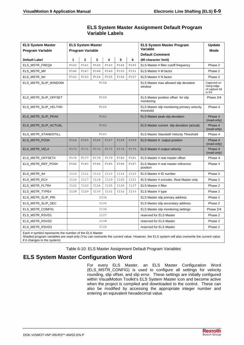
VisualMotion 9 Application Manual Electronic Line Shafting (ELS) 6-9
DOK-VISMOT-VM*-09VRS**-AW02-EN-P
ELS System Master Assignment Default ProgramVariable Labels
ELS System Master
Program Variable
ELS System Master
Program Variable
ELS System Master ProgramVariable
Default Comment
Update
Mode
Default Label 1 2 3 4 5 6 (80 character limit)
ELS_MSTR_FREQ# F140 F141 F142 F143 F144 F145 ELS Master # filter cutoff frequency Phase 2
ELS_MSTR_M# F146 F147 F148 F149 F150 F151 ELS Master # M factor Phase 2
ELS_MSTR_N# F152 F153 F154 F155 F156 F157 ELS Master # N factor Phase 2
ELS_MSTR_SLIP_WINDOW F158 ELS Master max allowed slip deviationwindow
Captured onrising edgeof capture bitin P4
ELS_MSTR_SLIP_OFFSET F159 ELS Master position offset for slipmonitoring
Phase 2/4
ELS_MSTR_SLIP_VELTHD F160 ELS Master slip monitoring primary velocitythreshold
Phase 4
ELS_MSTR_SLIP_PEAK F161 ELS Master peak slip deviation Phase 4(read-only)
ELS_MSTR_SLIP_ACTUAL F162 ELS Master current slip deviation (actual) Phase 4(read-only)
ELS_MSTR_STANDSTILL F163 ELS Master Standstill Velocity Threshold Phase 4
ELS_MSTR_POS# F164 F165 F166 F167 F168 F169 ELS Master # output position Phase 4(read-only)
ELS_MSTR_VEL# F170 F171 F172 F173 F174 F175 ELS Master # output velocity Phase 4(read-only)
ELS_MSTR_OFFSET# F176 F177 F178 F179 F180 F181 ELS Master # real master offset Phase 4
ELS_MSTR_REF_POS# F182 F183 F184 F185 F186 F187 ELS Master # real master referenceposition
Phase 4
ELS_MSTR_A# I110 I111 I112 I113 I114 I115 ELS Master # ID number Phase 2
ELS_MSTR_EC# I116 I117 I118 I119 I120 I121 ELS Master # encoder, Real Master only Phase 2
ELS_MSTR_FLTR# I122 I123 I124 I125 I126 I127 ELS Master # filter Phase 2
ELS_MSTR_TYPE# I128 I129 I130 I131 I132 I133 ELS Master # type Phase 2
ELS_MSTR_SLIP_PRI I134 ELS Master slip primary address Phase 2
ELS_MSTR_SLIP_SEC I135 ELS Master slip secondary address Phase 2
ELS_MSTR_CONFIG I136 ELS Master slip monitoring settings Phase 2/4
ELS_MSTR_RSVD1 I137 reserved for ELS Master Phase 2
ELS_MSTR_RSVD2 I138 reserved for ELS Master Phase 2
ELS_MSTR_RSVD3 I139 reserved for ELS Master Phase 2
Each # symbol represents the number of the ELS MasterShaded program variables are read-only (You can overwrite the current value. However, the ELS system will also overwrite the current valueif it changes in the system)
Table 6-10: ELS Master Assignment Default Program Variables
ELS System Master Configuration WordFor every ELS Master, an ELS Master Configuration Word(ELS_MSTR_CONFIG) is used to configure all settings for velocityrounding, slip offset, and slip error. These settings are initially configuredwithin VisualMotion Toolkit’s ELS System Master icon and become activewhen the project is compiled and downloaded to the control. These canalso be modified by accessing the appropriate integer number andentering an equivalent hexadecimal value.

6-10 Electronic Line Shafting (ELS) VisualMotion 9 Application Manual
DOK-VISMOT-VM*-09VRS**-AW02-EN-P
32 31 30 29 . . . 1
Reserved
Velocity Rounding
Slip Offset Method
Slip Error Reaction
ELS Master Configuration Word Bit Description
Fig. 6-3: ELS Master Configuration Word
This bit rounds the Virtual Master (VM#_CMD_VEL) and Group Jogging(G#_JOG_VEL) velocity down to the nearest ELS increment in order toeliminate small cycle-to-cycle variations in drive velocity that wouldotherwise occur.
0 = Disabled
1 = Virtual Master and Group Jogging velocities are rounded-down to thenearest ELS increment
In Absolute Position Monitoring mode this parameter is used as anabsolute offset between the two master encoders, this allows theFeedback/Master signals to have an offset between the two withoutneeding to mechanically zero the machine.
0= Fixed Absolute Offset – the value is static and you set an absoluteoffset between the two master encoders.
1= Dynamic Offset – the system automatically records the positiondifference between the two master signals when the control switches fromphase 2 to phase 4
This bit sets the system reaction to the master encoder signal exceedingthe maximum allowed deviation window limits.
0= Fatal Error (system stops)
1= Warning (user defined)
ELS System Master Variable DefinitionOnly Real Masters use the filter constant. When a filter(ELS_MSTR_FLTR#) is selected for an axis' position feedback, a cutofffrequency for the filter must be entered. The cutoff frequency is thefrequency where the signal is reduced by 3dB.
Only Real Masters use the ratio constants (M/N). The output of themaster is governed by the equation y=(M/N)*x, where x is the feedbackvalue from the real master and y is the master signal used for ELSGroups. All ELS Masters and ELS Groups outputs are modulo 360degrees.
This variable identifies a valid ID number for a defined master type. Forexample, when ELS_MSTR_TYPE# is set to 3 (Virtual Master) thisnumber must be a 1 or 2. Valid ID numbers are…
• Virtual Master: 1 or 2
• ELS Group Master: 1 - 8
• Real Master: 1 - 3
Bit 30Velocity Rounding
Bits 31Slip Offset Method
Bit 32Slip Error Reaction
ELS_MSTR_FREQ#
ELS_MSTR_M# and ELS_MSTR_N#
ELS_MSTR_A#

VisualMotion 9 Application Manual Electronic Line Shafting (ELS) 6-11
DOK-VISMOT-VM*-09VRS**-AW02-EN-P
When using an encoder device as a Real Master, this variable identifiesthe source.
• 0 = motor encoder
• 1 = external encoder
This variable identifies the type of filtering to use for the axis positionfeedback. Valid types are…
• 0 = no filter
• 1 = 1st order low pass
• 2 = 2nd order low pass
• 3 = 3rd order low pass
• 4 = 2nd order Butterworth
• 5 = 3rd order Butterworth
• 6 = 2nd order low pass with velocity feed forward
• 7 = 3rd order low pass with velocity and acceleration feed forward
Available master types are…
• 0 = Real Master
• 1 = ELS Group master
• 2 = External (future development)
• 3 = Virtual Master
• 4 = none
In absolute position monitoring mode, this sets the maximum allowableposition difference between the two selected master signals.
• Max Master velocity @ 2ms SERCOS = 7500 RPM
• Max Master velocity @ 4 ms SERCOS = 3750 RPM
• Max Master velocity @ 8 ms SERCOS = 1875 RPM (link ring)
In absolute position monitoring mode, this variable is used to offset twomaster encoders. This eliminates the need to mechanically zero themachine.
Range limits: -180° < X ≤ 180°
This is the velocity threshold that the primary master encoder mustexceed before the system is able to detect the direction of the primaryencoder.
In absolute positioning mode, this is used to store the peak slip positiondeviation between the primary and secondary master signals. EverySERCOS cycle, the system compares the value stored in this variable tothe current slip deviation. If this value is higher than any of the previousvalues, it will be set as the new peak deviation position. If you make achange to your program that lowers your peak value, you can write a zeroto the variable to force the program to overwrite it with the new peakvalue.
In absolute position mode, this variable displays the current positiondifference between the two selected master signals.
ELS_MSTR_EC#
ELS_MSTR_FLTR#
ELS_MSTR_TYPE#
ELS_MSTR_SLIP_WINDOW
ELS_MSTR_SLIP_OFFSET
ELS_MSTR_SLIP_VELTHD
ELS_MSTR_SLIP_PEAK
ELS_MSTR_SLIP_ACTUAL

6-12 Electronic Line Shafting (ELS) VisualMotion 9 Application Manual
DOK-VISMOT-VM*-09VRS**-AW02-EN-P
This variable is the velocity threshold that each master output mustexceed before the system sets the master status standstill bit to zero foreach given master (ELS_MSTR_STATUS, bits 1 to 6). This bit will only ohigh if the associated ELS System Master has been at or below thethreshold velocity for the last two SERCOS cycles.
This variable displays the current output position in degrees for each ofthe six master signals. This variable is stored in the control’s memoryand when the control is turned on and off, the last recorded value ismaintained. You can enter a value in the variable, but it will beoverwritten by the current value in the control.
This variable displays the current output velocity for each of the sixmaster signals.
This variable sets the address of the primary master signal to bemonitored.
Limits: 0 to 6 (0 not configured)
This variable sets the address of the secondary master signal to bemonitored.
This variable is used to set the different modes of operation for the mastersignal monitoring.
• 1 to 30 - Reserved
• 31 – slip offset method – 0 = Fixed Absolute Offset, 1 = DynamicOffset
• 32 – slip offset reaction – 0 = Fatal Error, 1 = Warning
Available registers:
• 1 to 14 - Reserved
• 15 – Capture Slip Monitoring (0 = Off, 1 = On)
Available registers:
• 1 – Master 1 at Standstill
• 2 – Master 2 at Standstill
• 2 – Master 3 at Standstill
• 2 – Master 4 at Standstill
• 2 – Master 5 at Standstill
• 2 – Master 6 at Standstill
• 7 to 13 - Reserved
• 14 – Monitoring ERROR Active (0 = No Error, 1 = Error)
• 15 – Lead Encoder (0 = Primary, 1 = Secondary)
• 16 – Slip Monistoring Enabled (0 = Not Enabled, 1 = Enabled)
ELS_MSTR_STANDSTILL
ELS_MSTR_POS#
ELS_MSTR_VEL#
ELS_MSTR_SLIP_PRI
ELS_MSTR_SLIP_SEC
ELS_MSTR_CONFIG
ELS_MSTR_CONTROL
ELS_MSTR_STATUS

VisualMotion 9 Application Manual Electronic Line Shafting (ELS) 6-13
DOK-VISMOT-VM*-09VRS**-AW02-EN-P
ELS Group 1- 8 Default Register LabelsThe default labels for the ELS Group registers are shown in Table 6-11.The corresponding default bit labels are shown in Table 6-13.
Data Object Type Label (20 character limit) Comment (80 character limit)
Assigned control register number G#_CONTROL_REG Group # control register
Assigned status register number G#_STATUS_REG Group # status register
Table 6-11: ELS Group 1- 8 Default Registers
Default LabelELS Group 1-8
Data ObjectELS Group Control Register-Bit
Comment (80 character limit)ELS Group 1-8
Control Register 1 2 3 4 5 6 7 8 Control Register
G#_CT_LOCK_OFF 152-1 153-1 154-1 155-1 156-1 157-1 158-1 159-1 Group # control, 0 → 1 start lockcycle, 1 → 0 start unlock
G#_CT_M_REL_PH 152-2 153-2 154-2 155-2 156-2 157-2 158-2 159-2 Group # control, 0 → 1 triggersmaster relative phase adjust
G#_CT_S_REL_PH 152-3 153-3 154-3 155-3 156-3 157-3 158-3 159-3 Group # control, 0 → 1 triggersslave relative phase adjust
G#_CT_MSTR_SEL 152-4 153-4 154-4 155-4 156-4 157-4 158-4 159-4 Group # control, 0=master 1,1=master 2
G#_CT_VAR_CLK 152-5 153-5 154-5 155-5 156-5 157-5 158-5 159-5 Group # control, 0 → 1 forcing
G#_CT_LOCAL 152-6 153-6 154-6 155-6 156-6 157-6 158-6 159-6 Group # control, 0 → 1 localmode, 1 → 0 selected master
G#_CT_JOG_INC 152-7 153-7 154-7 155-7 156-7 157-7 158-7 159-7 Group # control, 0=continuousjog mode, 1=incremental jogmode
G#_CT_JOG_ABS 152-8 153-8 154-8 155-8 156-8 157-8 158-8 159-8 Group # control, 0=absoluteincremental mode, 1=relativeincremental mode
G#_CT_JOG_PLUS 152-9 153-9 154-9 155-9 156-9 157-9 158-9 159-9 Group # control, 0 → 1 starts jogmode in positive direction
G#_CT_JOG_MINS 152-10 153-10 154-10 155-10 156-10 157-10 158-10 159-10 Group # control, 0 → 1 starts jogmode in negative direction
G#_CT_M_ABS_PH 152-11 153-11 154-11 155-11 156-11 157-11 158-11 159-11 Group # control, 0 → 1 triggersmaster absolute phase adjust
G#_CT_S_ABS_PH 152-12 153-12 154-12 155-12 156-12 157-12 158-12 159-12 Group # control, 0 → 1 triggersslave absolute phase adjust
Each # symbol represents an entry for the number of the ELS Group
Table 6-12: ELS Group 1- 8 Default Register Bits
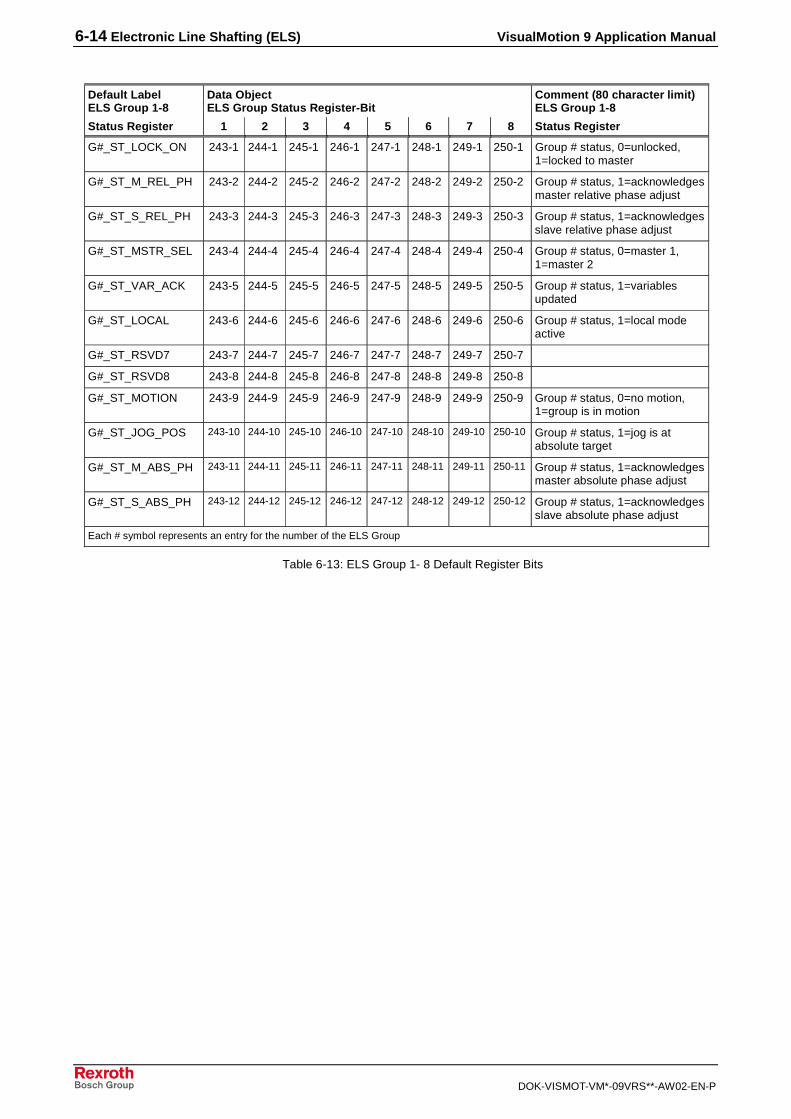
6-14 Electronic Line Shafting (ELS) VisualMotion 9 Application Manual
DOK-VISMOT-VM*-09VRS**-AW02-EN-P
Default LabelELS Group 1-8
Data ObjectELS Group Status Register-Bit
Comment (80 character limit)ELS Group 1-8
Status Register 1 2 3 4 5 6 7 8 Status Register
G#_ST_LOCK_ON 243-1 244-1 245-1 246-1 247-1 248-1 249-1 250-1 Group # status, 0=unlocked,1=locked to master
G#_ST_M_REL_PH 243-2 244-2 245-2 246-2 247-2 248-2 249-2 250-2 Group # status, 1=acknowledgesmaster relative phase adjust
G#_ST_S_REL_PH 243-3 244-3 245-3 246-3 247-3 248-3 249-3 250-3 Group # status, 1=acknowledgesslave relative phase adjust
G#_ST_MSTR_SEL 243-4 244-4 245-4 246-4 247-4 248-4 249-4 250-4 Group # status, 0=master 1,1=master 2
G#_ST_VAR_ACK 243-5 244-5 245-5 246-5 247-5 248-5 249-5 250-5 Group # status, 1=variablesupdated
G#_ST_LOCAL 243-6 244-6 245-6 246-6 247-6 248-6 249-6 250-6 Group # status, 1=local modeactive
G#_ST_RSVD7 243-7 244-7 245-7 246-7 247-7 248-7 249-7 250-7
G#_ST_RSVD8 243-8 244-8 245-8 246-8 247-8 248-8 249-8 250-8
G#_ST_MOTION 243-9 244-9 245-9 246-9 247-9 248-9 249-9 250-9 Group # status, 0=no motion,1=group is in motion
G#_ST_JOG_POS 243-10 244-10 245-10 246-10 247-10 248-10 249-10 250-10 Group # status, 1=jog is atabsolute target
G#_ST_M_ABS_PH 243-11 244-11 245-11 246-11 247-11 248-11 249-11 250-11 Group # status, 1=acknowledgesmaster absolute phase adjust
G#_ST_S_ABS_PH 243-12 244-12 245-12 246-12 247-12 248-12 249-12 250-12 Group # status, 1=acknowledgesslave absolute phase adjust
Each # symbol represents an entry for the number of the ELS Group
Table 6-13: ELS Group 1- 8 Default Register Bits

VisualMotion 9 Application Manual Electronic Line Shafting (ELS) 6-15
DOK-VISMOT-VM*-09VRS**-AW02-EN-P
ELS Group 1- 8 Default Program Variable Labels
Default LabelELS Group 1-8
Data ObjectELS Group 1-8 Program Variable
Comment (80 character limit)ELS Group 1-8
UpdateMode
Program Variable 1 2 3 4 5 6 7 8 Program Variable
G#_SYNC_ACCEL F190 F220 F250 F280 F310 F340 F370 F400 Group #, dynamic syncacceleration
Phase 4
G#_SYNC_VEL F191 F221 F251 F281 F311 F341 F371 F401 Group #, dynamic sync velocity Phase 4
G#_M1 F192 F222 F252 F282 F312 F342 F372 F402 Group #, M factor Phase 4& Forcing*
G#_N1 F193 F223 F253 F283 F313 F343 F373 F403 Group #, N factor Phase 4& Forcing*
G#_PROG_M_PH F194 F224 F254 F284 F314 F344 F374 F404 Group #, master phase adjustvalue
Phase 4
G#_PROG_S_PH F195 F225 F255 F285 F315 F345 F375 F405 Group #, slave phase adjustvalue
Phase 4
G#_ABS_M_PH F196 F226 F256 F286 F316 F346 F376 F406 Group #, absolute master phaseadjust
Phase 4(read-only)
G#_ABS_S_PH F197 F227 F257 F287 F317 F347 F377 F407 Group #, absolute slave phaseadjust
Phase 4(read-only)
G#_H_LOCKON F198 F228 F258 F288 F318 F348 F378 F408 Group #, H factor lock on camprofile
Phase 4& Forcing*
G#_H_RUN F199 F229 F259 F289 F319 F349 F379 F409 Group #, H factor 1:1 cam profile Phase 4& Forcing*
G#_H_LOCKOFF F200 F230 F260 F290 F320 F350 F380 F410 Group #, H factor lock off camprofile
Phase 4& Forcing*
G#_H_USER F201 F231 F261 F291 F321 F351 F381 F411 Group #, H factor user camprofile
Phase 4
G#_LOCK_WIN F202 F232 F262 F292 F322 F352 F382 F412 Group #, shortest path windowfor dynamic sync. phasecorrection
Phase 4
G#_STOP_DECEL F203 F233 F263 F293 F323 F353 F383 F413 Group #, stop ramp deceleration Phase 4
G#_JOG_ACCEL F204 F234 F264 F294 F324 F354 F384 F414 Group #, jog acceleration Phase 4
G#_JOG_VEL F205 F235 F265 F295 F325 F355 F385 F415 Group #, jog velocity Phase 4
G#_JOG_INC F206 F236 F266 F296 F326 F356 F386 F416 Group #, relative positiondistance (incremental jog)
Phase 4
G#_JOG_ABS F207 F237 F267 F297 F327 F357 F387 F417 Group #, absolute position target(absolute jog)
Phase 4
G#_JOG_WIN F208 F238 F268 F298 F328 F358 F388 F418 Group #, shortest path windowfor absolute jog
Phase 4
G#_LOCKON_OFFSET F209 F239 F269 F299 F329 F359 F389 F419 Group #, offset added to theoutput when lock on cam profileis being forced
Phase 4
G#_IN_POS F210 F240 F270 F300 F330 F360 F390 F420 Group #, input position Phase 4& Forcing*
G#_IN_VEL F211 F241 F271 F301 F331 F361 F391 F421 Group #, input velocity (readonly)
Phase 4
G#_OUT_POS F212 F242 F272 F302 F332 F362 F392 F422 Group #, output position (readonly)
Phase 4& Forcing*
G#_OUT_VEL F213 F243 F273 F303 F333 F363 F393 F423 Group #, output velocity (readonly)
Phase 4
Table 6-14: ELS Group 1- 8 Default Program Variables (part 1 of 2)

6-16 Electronic Line Shafting (ELS) VisualMotion 9 Application Manual
DOK-VISMOT-VM*-09VRS**-AW02-EN-P
ELS Group 1- 8 Default Program Variable Labels (Cont'd)
Default LabelELS Group 1-8
Data ObjectELS Group 1-8 Program Variable
Comment (80 character limit)ELS Group 1-8
UpdateMode
Program Variable 1 2 3 4 5 6 7 8 Program Variable
G#_OUT_ACC F214 F244 F274 F304 F334 F364 F394 F424 Group #, output acceleration(read only)
Phase 4
G#_CAM_INPUT F215 F245 F275 F305 F335 F365 F395 F425 Group #, group cam profile IDinput position
Phase 4& Forcing*
G#_MST1_TRIGPOS F216 F246 F276 F306 F336 F366 F396 F426 Group #, master 1 switchingtrigger position
Phase 4
G#_MST1_TRIGPOS F217 F247 F277 F307 F337 F367 F397 F427 Group #, master 2 switchingtrigger position
Phase 4
G#_STANDSTILL_WIN F218 F248 F278 F308 F338 F368 F398 F428 Group # standstill velocitythreshold
Phase 4
G#_CONFIG I140 I150 I160 I170 I180 I190 I200 I210 Group #, configuration word Refer toFig. 5-2
G#_MSTR1_AXIS I141 I151 I161 I171 I181 I191 I201 I211 Group #, ELS master ID,number 1
Phase 4
G#_MSTR2_AXIS I142 I152 I162 I172 I182 I192 I202 I212 Group #, ELS master ID,number 2
Phase 4
G#_ACTIVE_STATE I143 I153 I163 I173 I183 I193 I203 I213 Group #, active state of statemachine for lockon/lockoff
Phase 4& Forcing*
G#_ACTIVE_CAM I144 I154 I164 I174 I184 I194 I204 I214 Group #, active cam profile tablenumber
Phase 4
G#_LOCKON_CAM I145 I155 I165 I175 I185 I195 I205 I215 Group #, lock on cam profiletable number
Phase 4& Forcing*
G#_RUN_CAM_ID I146 I156 I166 I176 I186 I196 I206 I216 Group #, 1:1 cam profile tablenumber
Phase 4& Forcing*
G#_LOCKOFF_CAM I147 I157 I167 I177 I187 I197 I207 I217 Group #, lock off cam profiletable number
Phase 4& Forcing*
G#_USER_CAM I148 I158 I168 I178 I188 I198 I208 I218 Group #, user cam profile tablenumber (state machine disabled)
Phase 4
* Forcing is reinitializing an ELS Group in Phase 4 when local mode is active (G#_ST_LOCAL) and the ELS Group Master is at standstill(G#_ST_MOTION is 0).
Table 6-15: ELS Group 1- 8 Default Program Variables (part 2 of 2)

VisualMotion 9 Application Manual Electronic Line Shafting (ELS) 6-17
DOK-VISMOT-VM*-09VRS**-AW02-EN-P
ELS Group Configuration WordFor every ELS Group, an ELS Group configuration word (G#_CONFIG) isused to configure all settings for Switching Synchronization, PhaseControl and Initialization. These settings are initially configured withinVisualMotion Toolkit's ELS Group icon and become active when theproject is compiled and downloaded to the control. These settings canalso be modified by accessing the appropriate integer number andentering an equivalent hexadecimal value.
12 11 10 9 8 7 6 5 4 3 2 1
unused
Sync. to ELS Group master
Enable CAM profiling
Synchronization Type
Phase correction type
ELS Group master positioninitialization at Phase 2
Group master position evaluationwith forcing
Master phase adjust type
Slave phase adjust type
ELS Group Configuration Word Bit Description
24 23 22 21 20 19 18 17 16 15 14 13
Advanced Master SwitchingOptions
Enable Master 1 SwitchingTriggers
Enable Master 2 SwitchingTriggers
Master 2 Switching Type
Master 2 Phase Correction Type
Fig. 6-4: ELS Group Configuration Word Description
When the control is switched to manual mode, all ELS Groups areswitched to local mode. In local mode, each ELS Group can be joggedindependently. When switching back to automatic mode, the user canconfigure bit 2 using the following two options:
0 = Automatically switch back to the ELS Group master and perform adynamic synchronization if necessary, see bits 5, 6 and 7 (default)
1 = Groups will stay in local mode and must be switched manually
(Updated in Phase 2)
This bit enables the lock on / lock off CAM profile state. For user CAMprofiles to function, disable this feature.
0 = state machine enabled (default)
1 = state machine disabled
(Updated in Phase 2)
Bit 2:Sync. to ELS Group Master
Bit 4:Enable CAM Profiling
6-18 Electronic Line Shafting (ELS) VisualMotion 9 Application Manual
DOK-VISMOT-VM*-09VRS**-AW02-EN-P
Modifications to the variable G#_H_USER can only be performed whenthe state machine is disabled. While disabled, the user can select a CAMprofile for the ELS Group and modify the G#_H_USER factor. Whenenabled, the state machine uses as an H factor the values ofG#_H_LOCKON, G#_H_LOCKOFF and G#_H_RUN. The G#_H_USERvariable displays the current H factor being used for the lock on and lockoff cam profiles.
This bit is used to specify the type of synchronization that will be usedwhen switching between ELS Group input masters 1 and 2 or only Groupmaster 1 in Advanced Mode (see bit 22 for master 2)..
0 = Dynamic synchronization (default)
1 = Immediate (On the Fly when switching to an unused Virtual Master)
(Updated in Phase 4)
When bit 5 is set to 1 and an ELS Group's input master is switched to anunused Virtual Master, this Virtual Master will adapt "On the Fly" to thecurrent ELS Group master's position and velocity.
These bits determine method of phase correction during DynamicSynchronization between group input masters 1 and 2 or for group inputmaster 1 only in Advanced Mode (see bits 23, 24 for group 2).
Bit 6 Bit 7 Description
0 0 Shortest path (default)
1 0 Positive direction if phase difference is greater than"G#_LOCK_WIN". Otherwise, use shortest path.
0 1 Negative direction if phase difference is greater than"G#_LOCK_WIN". Otherwise, use shortest path.
1 1 No phase correction (only velocity synchronization isperformed)
(Updated in Phase 4)
This bit is used to reinitialize an ELS Groups output master position whenthe system is switched to Phase 2 (parameter mode) or powered down.
When an ELS Group's M/N or H factor has a value other than 1; forexample 0.9, and the ELS Group has been moved, then the group'soutput master position cannot be calculated using the CAM equation.
The reason for this is as follows:
The control monitors and internally stores the ELS Group's current outputposition. For example, if after two revolutions of the input master (asillustrated in Fig. 6-5), the system is switched to Phase 2 or loses power;the ELS Group's output master position is stored. The user has theoption to restart the ELS Group, to an initial position, by setting bit 8 to 0.This will recalculate the ELS Group's output master position using theCAM equation. Setting bit 8 to 1 allows the ELS Group's output masterposition to start from the stored position (old values) and continue; usingthe CAM equation, for consecutive revolutions of the ELS Group's inputmaster.
Bit 5:Synchronization Type
Bit 6-7:Phase Correction Type
Bit 8:ELS Group Master Position
Initialization at Phase 2

VisualMotion 9 Application Manual Electronic Line Shafting (ELS) 6-19
DOK-VISMOT-VM*-09VRS**-AW02-EN-P
[(input master * M/N) + master offset]H + slave offset = Group output
[(0° * 0.9) + 0°] * 1 + 0° ⇒ 0° ;initial position at start
[(0° * 0.9) + 0°] * 1 + 0° ⇒ 324° ;after one revolution
[(0° * 0.9) + 0°] * 1 + 0° ⇒ 288° ;after second revolution
Group output position with a 0.9 M/N and no offsets
Fig. 6-5: CAM Equation Example
0 = Initialization with calculated value using the cam equation (default)
1 = Use old values
(Updated in Phase 2 & Forcing)
This bit is used to initialize an ELS Group's output position when switchedto local mode (G#_CT_LOCAL).
0 = Group master positions will be calculated using cam equation (default)
1 = Use old values
(Updated in Phase 2 & Forcing)
When forcing states 0 or 1 with this bit reset, G#_ LOCKON_OFFSET isadded to the group master output position. If this bit is set, G#_LOCKON_OFFSET is not used.
This bit sets the motion profile type for the active master.
0 = Trapezoidal profile using a velocity profile with dynamic synchronizationacceleration/deceleration and additive velocity (default)
1 = Immediate – step function
(Updated in Phase 4)
This bit sets the motion profile type for the all slave axis associated withthe ELS Group.
0 = Trapezoidal profile using a velocity profile with dynamic synchronizationacceleration/deceleration and additive velocity (default)
1 = Immediate – step function
(Updated in Phase 4)
Advanced Master Switching Options
0 = Disabled – Enables ELS Group Master Switching functionality inVisualMotion 8
1 = Enabled – Enables Enhanced ELS Group Master Switching
These bits specify a condition that must be met before the process ofswitching to group master 1 is triggered.
Bit 18 Bit 19 SwitchingTrigger
Description
0 0 Instantaneous(default)
Master switching is triggered as soon asthe G#_CT_MSTR_SEL group control bitis changed.
Bit 9:Group Master Position
Evaluation with Forcing
Bit 11:Master Phase Adjust Type
Bit 12:Slave Phase Adjust Type
Bits 17:
Bits 18-19:

6-20 Electronic Line Shafting (ELS) VisualMotion 9 Application Manual
DOK-VISMOT-VM*-09VRS**-AW02-EN-P
Bit 18 Bit 19 SwitchingTrigger
Description
1 0 Master 1 Position Master switching is triggered when GroupMaster 1 passes (moving in the positivedirection) the position defined in floatvariable G#_MSTR1_TRIGPOS
0 1 Master 2 Position Master switching is triggered when GroupMaster 2 passes (moving in the positivedirection) the position defined in floatvariable G#_MSTR2_REIGPOS
1 1 Optimal Dynamic Switching: switching istriggered when the group’s constantacceleration ramp (using G#SYNC_ACC)will result in the group synchronizing tothe target master’s position and velocitynearly simultaneouslyImmediate switching: switching istriggered when the groups master’spositions coincide
These bits specify a condition that must be met before the process ofswitching to group master 2 is triggered. The bit format is the same as forbits 18-19.
This bit indicates the type of ELS group master synchronization usedwhen switching to group master 2. This requires the Master SwitchingOption bit to be set.
0 = Dynamic synchronization
1 = Immediate synchronization
This bit indicates the options for phase correction during dynamicsynchronization when switching to group master 2. This requires theMaster Switching Option bit to be set. The bit format is the same as bits 6and 7.
6.3 Virtual Master
A Virtual Master is an internal motion profiler that drives geared orcammed axes in a machine. A set of control and status parameters andregisters command the axis to run at a set speed, stop at a position, ormake a profiled move. The command stream is based on units ofdegrees and has a range between 0 and 360 degrees; with the module(rollover period) fixed at 360 degrees. This output format (0 and 360)forms the basis for the entire ELS system, where a machine/product cycleis defined as a single revolution. For example, a system commanded bya Virtual Master running at 300 RPM produces 300 products per minute.
A Virtual Master is controlled by a VisualMotion project and/or a PLCusing I/O registers and project variables. The initialization of theseregisters and project variables is defined in the Virtual Master icon.
GPP supports a maximum of 2 Virtual Masters. The Virtual Master 1 & 2Setup window contains fields for designating the control and statusregister numbers and associated floats and integers. The window openswith default values that are part of VisualMotion. Registers 150 to 159 areassociated with ELS functionality.
To define Virtual Masters in a project, open the Initialization task pallet,select the Virtual Master Setup Icon, and place it in the projectworkspace. Even though the Virtual Master is defined in the Initializationtask, it is always tied to the status/diagnostic state of the task A, a fatalerror in this task will cause the Virtual master to stop. Conversely theVirtual Master can be controlled from anywhere in the runtime program
Bits 20-21
Bit 22
Bits 23-24

VisualMotion 9 Application Manual Electronic Line Shafting (ELS) 6-21
DOK-VISMOT-VM*-09VRS**-AW02-EN-P
and/or outside the system from a PLC using the defined control registersand parameter variables. Virtual Master 1 or 2 signals can not be useddirectly, they must first be defined as one of the six system masters, thenused to drive a group master input, PLS or Rotary event.
Assigning Initial ValuesThe Assign Initial Values … button in the Virtual Master 1 & 2 Setupwindow opens a window where the initial and maximum values foroperating and positioning the Virtual Master can be set, see Fig. 6-6.
vm_init_values.tif
Fig. 6-6: Virtual Master Compile Time Initialization
Initial and Maximum ValuesThe initial and maximum values set for each Virtual Master in the CompileTime Initialization window are embedded in the icon. During programcompiling, the values are stored as project variables. The default valuesassigned to the default labels are typical values hard coded in the icon.These values should be changed according to the type of motion youwant to generate, but if the values cause the limits of the motor and driveto be exceeded, a fault will occur.
Note: These values in the setup dialog are a one time initializationduring the download process and can later be changed usingthe online tools or in the runtime program. Changes madeonline will not be reflected in the offline project and overwrittenthe next compile/download. You must edit the fields in theicon if you want to make a permanent change.
The Initial Velocity value defines a constant velocity that the Virtual Masterwill accelerate towards when set in motion.
The Maximum Velocity value defines the maximum velocity that can beachieved by the Virtual Master during runtime.
Velocity

6-22 Electronic Line Shafting (ELS) VisualMotion 9 Application Manual
DOK-VISMOT-VM*-09VRS**-AW02-EN-P
Note: The Virtual Master moves in a clockwise (positive) directionwhen a non-negative velocity value is used. A negativevelocity value causes the Virtual Master to move in a counterclockwise (negative) direction.
The velocity the drive (axes) can obtain following a Virtual Master islimited by the drive's Bipolar Velocity Limit. The following conditions alsoaffect the drive velocity:
• If the Virtual Master's maximum velocity is less than the drive's BipolarVelocity Limit Value (S-0-0091), the drive is limited by the VirtualMaster.
• If the Virtual Master's maximum velocity is greater than the drive'sBipolar Velocity Limit Value (S-0-0091), the drive will fault whenS-0-0091 is exceeded.
The Initial Acceleration value defines a constant acceleration that theVirtual Master will use to achieve a desired velocity.
The Maximum Acceleration value defines the maximum acceleration thatcan be achieved by the Virtual Master during runtime.
The Initial Deceleration value defines a constant deceleration that theVirtual Master will use to decelerate the velocity.
The Maximum Deceleration value defines the maximum deceleration thatcan be achieved by the Virtual Master during runtime.
This value specifies the emergency stop deceleration for each VirtualMaster.
PositioningPositioning values are embedded in the icons and are stored as projectvariables when the project is compiled.
The Virtual Master starts a ramped homing move to the home positionwhen a low-to-high transition is seen in the Virtual Master control registerbit:
Control Register Bit State
Bit 2 (VM#_CT_HOME) 0 → 1
This value is written to project variable VM#_HOME_POS within 1SERCOS cycle when the project is compiled. The move is executedusing shortest-path positioning and its ramp is defined by the VirtualMasters Maximum Velocity (VM#_MAX_VEL), Maximum Acceleration(VM#_MAX_ACC), and Maximum Deceleration (VM#_MAX_DEC) values.
The bit transition will be ignored if the VM#_CT_GO bit is high or if theVirtual Master is actively being used by an ELS Group. If these conditionsexist, the VM#_CT_HOME bit will stay low to indicate that the homingrequest has been ignored. Otherwise, the virtual master’s home status bitwill be raised after the virtual master has been set to the home position toindicate the operation is complete.
This is the programmed stop position the Virtual Master moves to whenthe control is switched from velocity mode to absolute positioning mode.This field contains the initial value that is written to project variableVM#_STOP_POS when the project is compiled. The state of thefollowing bits determine the mode of operation:
Acceleration
Deceleration
E-Stop Deceleration
Home
Stop

VisualMotion 9 Application Manual Electronic Line Shafting (ELS) 6-23
DOK-VISMOT-VM*-09VRS**-AW02-EN-P
Control Register Bit Velocity Mode Absolute Position Mode
Bit 3 (VM#_CT_GO) 1 1
Bit 4 (VM#_CT_VMODE) 0 → 1(velocity mode)
1 → 0(moves to stop position)
Once Velocity Mode is turned off (Bit 4 = 0), the value inVM#_STOP_POS is written to the project variable VM#_CMD_ABS_POSand the Virtual Master moves to the ABS_POS. The control is nowoperating in absolute positioning mode.
The Virtual Master moves in increments of this value when the VirtualMaster's control register bits are set as follows:
Control Register Bit State
Bit 3 (VM#_CT_GO) 1
Bit 5 (VM#_CT_RELMODE) 1
Bit 6 (VM#_CT_RELTRIG) 0 → 1 (will move with every transition)
This value is written to project variable VM#_REL_MOVE_DIST when theproject is compiled.
Positioning values are embedded in the icons and are stored as projectvariables when the project is compiled. This value is written to projectvariable VM#_CMD_ABS_POS. The state of the following bits set themode of operation to absolute position.
Control Register Bit State
Bit 3 (VM#_CT_GO) 0 → 1
Bit 4 (VM#_CT_VMODE) 0
When bit 3 is set to 1, the Virtual Master moves to the value in projectvariable VM#_CMD_ABS_POS. Any change to this value, while inabsolute position mode, will cause the Virtual Master to move to the newposition.
If the Virtual Master's mode of operation is switched from velocity toabsolute position, the value in VM#_CMD_ABS_POS is replaced with thevalue in project variable VM#_STOP_POS. Only positive values can beused for an absolute position move
This selection determines the direction that the Virtual Master will usewhen moving to the Absolute Move Position variable. This value is writtento project variable VM#_POS_MODE when the project is compiled. Thefollowing choices are as follows:
• Positive (0 in VM#_POS_MODE)
• Negative (1 in VM#_POS_MODE)
• Shortest Path (2 in VM#_POS_MODE)
This value (0-180°) is used to create a "shortest path" positioning windowfor the Virtual Master's positive and negative move mode. When theAbsolute Move Mode is set to positive or negative, the Virtual Master willmove in the specified direction unless the new target position is inside thepositioning window. If so, then shortest path will be used. Once theVirtual Master has moved to a new absolute position, a new positioningwindow is created around the new position. This feature is not availablewhen the Absolute Move Mode is set to Shortest Path. Fig. 6-7 illustratesthe function of this value.
Relative Move Distance
Absolute Move Position
Absolute Move Mode
Max. phase difference allowedfor shortest path correction

6-24 Electronic Line Shafting (ELS) VisualMotion 9 Application Manual
DOK-VISMOT-VM*-09VRS**-AW02-EN-P
��������������� !��" �#!# �#�$�%#�� %
&'����!�(�)'�� *�+,-&+�-�.�-/0�
�
�
��1�(�)'�� *�������+,-/0�-�2�
���3
��3
���3
/ �#!# �#�$��#�� %���*#���
�
�
��1�(�)'�� *�������+,-/0�-�2�
���$�!�" �#!# ��* ��+,-&+�-�.�-/0�
�� �!��!�"�!�%#))�4��'���
2*�!���!��$�!�" �#!# ��#���������!��" �#!# �#�$�%#�� %5�!����� �!��!�"�!��%#))4��'������$���)����#*�!�����!!#�$�#��!���4� )'!��6 (��6 ���(��#�4)��+,-/0�-+0���#��" �#!#(�� ����$�!#(�
���3
��3
���3
�� �!��!�/�!�
2*�!���!��$�!�" �#!# ��#����������!��" �#!# �#�$�%#�� %5�!�����!!#�$�#��!���4� ')!��6 (��6 ���(��#�4)��+,-/0�-+0���%#))�4��'���
��1�(�)'�� *�������+,-/0�-�2�
���$�!�" �#!# ��* ��+,-&+�-�.�-/0�
�
�
/�!��!�7���%����+,-/0�-+0���#���!�! ���$�!#(�
/�!��!�7���%����+,-/0�-+0���#���!�! �" �#!#(�
���3
��3
���3
/ �#!#(�� ����$�!#(��/�!�
phase_difference.EPS
Fig. 6-7: Maximum Phase Difference
This allows you to limit the jerk of a motion, such as vibration caused byacceleration or deceleration.
Virtual Master Modes of OperationThe Virtual Master can operate in two modes, velocity or position mode.The mode is determined by the settings selected in Virtual MasterCompile Time Initialization window. By default, the Virtual Master is set invelocity mode with values in the Initial and Maximum fields for velocity.Position mode requires values in the Positioning field of the window. Inaddition, by selecting the VM1_CT_RELMODE bit, the Virtual Master willswitch to relative mode.
Velocity ModeIn Velocity mode, the Virtual Master moves at its commanded velocity.The rate of change in the commanded velocity (VM#_CMD_VEL) isperformed using the defined acceleration/deceleration(VM#_CMD_ACCEL, …DECEL) rate. In this mode, the Virtual Mastercan be either stopped with immediate deceleration or stopped at adesignated position between 0 and 360 degrees. Stopping the master ata designated position may take several revolutions (stop ramp) dependingon the current velocity and programmed deceleration.
When a master is in velocity mode, an integrator is engaged, providingpositional output so that all masters have a uniform signal type (positionvalue with modulo of 360 degrees.)
Position ModeIn Position mode, the Virtual Master moves to a programmed relative orabsolute position. With relative positioning, travel distances can be
Jerk Limiting

VisualMotion 9 Application Manual Electronic Line Shafting (ELS) 6-25
DOK-VISMOT-VM*-09VRS**-AW02-EN-P
greater than the modulo value for relative positioning moves of the VirtualMaster. For absolute positioning, the maximum travel distance is +/- 180degrees (shortest path) or 359.99 degrees (positive or negative direction)with absolute positioning.
6.4 Real Master
A Real Master is an external position signal that is brought into the controlthrough the System Master icon. GPP supports a maximum of 6 realmasters. Because PPC hardware has no provisions for accepting afeedback signal, all signals are input through the optional encoder inputport on the servo drive and sent over the SERCOS ring to the control.
After properly configuring the optional encoder parameters in the driveand setting up the System Master icon, there will be a signal ready to beused. The command stream is based on units of degrees and has arange between 0 and 360 degrees with the module (rollover) fixed at 360degrees. This output format (0 to 360 degrees) is the basis for the ELSsystem position where a machine/product cycle is defined as a singlerevolution. For example, a system following a real master running at 300RPM produces 300 products per minute.
To define a Real Master in the project, go to the Initialization task andlocate the ELS System Master Setup icon in the pallet and place it in theproject workspace. Select the master type and fill out the configurationparameters described below.
Setup_ELS_Mstr.tif
Fig. 6-8: Setup ELS System Master: Real Master
This field contains the edit boxes for the gear ratio. A gear ratio is onlyapplicable to real master signals.
In this field, you can select primary or secondary encoder and single ormulti turn encoder type:
• Primary encoder – This is the motor feedback encoder (X4 ECODrive03)
• Secondary encoder – this is the extra encoder input at the drive (X8ECODrive 03)
Coupling (float)
Encoder

6-26 Electronic Line Shafting (ELS) VisualMotion 9 Application Manual
DOK-VISMOT-VM*-09VRS**-AW02-EN-P
• Multi turn checkbox – this option can be selected if the feedback is amultiturn absolute device and you want the system to track its absoluteposition. To reset (home) the current reference value, set the SystemMaster, control register, ELS_M_CT_SET_REF# input bit to 1. Thiscauses the respective system master to instantly move to the positionstored in the ELS_MSTR_REF_POS# parameter. To assure thesystem comprehends the absolute position, monitor the status bitELS_M_ST_REF#. This bit is cleared every time the parameterscontrolling the system master are changed or, in the case of anincremental encoder, when the system goes from phase 2 to phase 4.
For a real master signal, you can apply several types of filters to dampennoise in the signal. These filters include:
• Low-pass (1st, 2nd, or 3rd)
• Butterworth (2nd or 3rd)
• LP(2nd)+vel ramp
• LP(3rd)+accel ramp
If a filter type is selected, the frequency cutoff field is active. When settingthe frequency cutoff, the lower the cutoff frequency value, the earlier thefilter dampens the frequency.
Dead time compensation can be activated or disabled for the cut offfrequency by selecting this checkbox in the Setup ELS System Master 1window. This feature provides the option to apply 4 SERCOS cycles ofvelocity feed forward phase advance to the ELS Master, when activated,to compensate for delays in control processing.
Dead Time Compensation only compensates for the phase lag created bythe 4 cycles of ELS processing/SERCOS delays, not for additional deadtime caused by the various Real Master filters.
Positioning a Secondary Encoder SignalA secondary encoder signal can be used as a master axis position.Within the drive, the offset position feedback value 3 (drive parameter P-0-0087) is applied to the secondary encoder value (refer to illustration inFig. 6-9). A gear ratio of only integer values, stored as floatsELS_MSTR_M1…6 and ELS_MSTR_N1…6, is applied to the positionfeedback if required, for example, using a gear ratio to offset themechanical gear setting.
A reference position for the position feedback value 3 is set in the floatvariable ELS_MSTR_REF_POSx (where x is the ELS Master numberfrom 1 to 6). To send the reference position to feedback value 3:
1. Place the ELS Group axis (following the secondary encoder feedbacksignal) in local mode.
2. Toggle the ELS_M_CT_SET_REFx (where x is a number from 1 to 6)bit of the ELS_MSTR_CONTROL register.
3. Verify the homing sequence with the ELS_M_ST_REFx (where x is anumber from 1 to 6) bit of the ELS_MSTR_STATUS register.
An offset is calculated from the comparison of the current feedbackposition and homing position and is stored in the ELS_MSTR_OFFSETxvariable (where x is a number from 1 to 6). The offset is referenced laterwhen the master axis position is set. A filter is added to the feedbackposition (filter type selected in the Setup ELS System Master window, Fig.6-8) to smooth the signal. The ELS Master position is stored in theELS_MSTR_REF_POSx variable (where x is a number between 1 to 6).
Filter Type
Cutoff Frequency (float)
Velocity Dead TimeCompensation
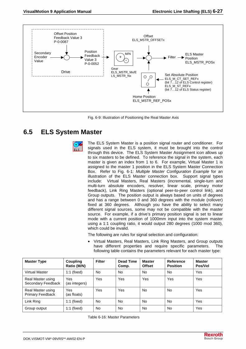
VisualMotion 9 Application Manual Electronic Line Shafting (ELS) 6-27
DOK-VISMOT-VM*-09VRS**-AW02-EN-P
SecondaryEncoderValue
Offset PositionFeedback Value 3P-0-0087
PositionFeedbackValue 3P-0-0052
OffsetELS_MSTR_OFFSETx
FilterELS MasterPositionELS_MSTR_POSx
Home PositionELS_MSTR_REF_POSx
Set Absolute PositionELS_M_CT_SET_REFx(bit 7…12 of ELS Control register)ELS_M_ST_REFx(bit 7…12 of ELS Status register)
DriveGearELS_MSTR_Mx/ELS_MSTR_Nx
++
M/N
Fig. 6-9: Illustration of Positioning the Real Master Axis
6.5 ELS System Master
The ELS System Master is a position signal router and conditioner. Forsignals used in the ELS system, it must be brought into the controlthrough this device. The ELS System Master Assignment icon allows upto six masters to be defined. To reference the signal in the system, eachmaster is given an index from 1 to 6. For example, Virtual Master 1 isassigned to the master 1 position in the ELS System Master ConnectionBox. Refer to Fig. 6-1: Multiple Master Configuration Example for anillustration of the ELS Master connection box. Support signal typesinclude: Virtual Masters, Real Masters (incremental, single-turn andmulti-turn absolute encoders, resolver, linear scale, primary motorfeedback), Link Ring Masters (optional peer-to-peer control link), andGroup outputs. The position output is always based on units of degreesand has a range between 0 and 360 degrees with the module (rollover)fixed at 360 degrees. Although you have the ability to select manydifferent signal sources, some may not be compatible with the mastersource. For example, if a drive’s primary position signal is set to linearmode with a current position of 1000mm input into the system masterusing a 1:1 coupling ratio, it would output 280 degrees (1000 mod 360),which could be invalid.
The following are rules for signal selection and configuration:
• Virtual Masters, Real Masters, Link Ring Masters, and Group outputshave different properties and require specific parameters. Thefollowing table contains the parameters relevant for each master type:
Master Type CouplingRatio (M/N)
Filter Dead TimeComp.
MasterOffset
ReferencePosition
MasterPos/Vel
Virtual Master 1:1 (fixed) No No No No Yes
Real Master usingSecondary Feedback
Yes(as integers)
Yes Yes Yes Yes Yes
Real Master usingPrimary Feedback
Yes(as floats)
Yes Yes No No Yes
Link Ring 1:1 (fixed) No No No No Yes
Group output 1:1 (fixed) No No No No Yes
Table 6-16: Master Parameters

6-28 Electronic Line Shafting (ELS) VisualMotion 9 Application Manual
DOK-VISMOT-VM*-09VRS**-AW02-EN-P
The ELS Setup and Runtime windows display only applicable parameters.
• To use the primary motor feedback as a master source signal, thedrive must be set to modulo operation (not absolute) and the modulovalue (S-0-0103) must be set to 360 degrees.
To define the System Masters in the project go to the Initialization taskpallet in VisualMotion and select the ELS System Master Setup icon andplace it in the project workspace.
Masters are assigned by double-clicking a Master number in the ELSSystem Master Assignment window. This opens the Setup ELS SystemMaster 1 window where the master type and number are set, see Fig. 6-8.
els_master_assign.tif
Fig. 6-10: ELS Master Assignment
Default variable and register numbers are displayed in the ELS SystemMaster Assignment window when it is opened. The settings can bechanged to any non-restricted system registers. The variable labels canalso be assigned with the default labels and numbers by accepting alldefault settings.
Velocity Rounding sets the Virtual Master and Group jogging velocitiesdown to the nearest ELS increment to eliminate cycle-to-cycle variationsin drive velocity. This results in the velocities being slightly less than theircommanded values. This feature can be enabled and disabled in bit 30(ELS_MSTR_CONFIG) of the ELS Group Configuration Word.
6.6 ELS Group Master
An ELS Group signal is the output signal from an ELS Group which isused by another ELS Group. An ELS Group can output a signal to anELS Group slave axis, to another ELS Group, or to both. The signal thatis output to another ELS Group is assigned a number in the ELS SystemMaster Connection box as an ELS Group Master. When assigning theELS Group Master signals, the concept referred to as cascading isapplied to group assignment.
Cascading ELS GroupsA maximum of 6 ELS Group Masters can be cascaded to other ELSGroups. When cascading ELS Groups, the lower numbered group’soutput should become the higher numbered group’s input. An ELS GroupMaster’s output cannot be fed back into the same ELS Group’s input. If agroup number is inputted into a lower group number, then there will be a
Variable Assignment
Velocity Rounding

VisualMotion 9 Application Manual Electronic Line Shafting (ELS) 6-29
DOK-VISMOT-VM*-09VRS**-AW02-EN-P
position delay of one SERCOS cycle. This delay is due to the fact that thegroup outputs are processed in numerical sequence and data from thelast cycle is used before it can be updated. Depending on the application,this lag may be acceptable.
Note: All motion is associated with task A. Any motion associatedwith ELS Groups within the VisualMotion project will stop iftask A stops.
1 2 3 4 5 6ELS MasterConnection Box
Cascading to ELS Groups
ELSGroup 1
ELSGroup 2
ELSGroup 3
ELSGroup 4
ELSGroup 5
ELSGroup 6
ELSGroup 8
ELSGroup 7
VM1 VM2
Fig. 6-11: Cascading an ELS Group Master Output
GPP supports a maximum of 6 ELS Group Masters, which are configuredthrough the ELS System Master icon. To configure, assign the ELSmaster type and the ELS Group Master number (the number indicatingwhich ELS Group Master it is, not its number designation in the ELSMaster Connection Box).
6.7 Link Ring Master
A Link Ring Master is an external position signal sent over a fiber opticring and received by the control using the DAQ option card. The fiberoptic ring can interface with up to 32 controls. GPP will support amaximum of 5 Link Ring Master signals received from other controls inthe system and export a maximum of one master signal to the Link Ringfor use by other controls. The position signals are based on units ofdegrees and have a range between 0 and 360 degrees with the module(rollover) fixed at 360 degrees. For more information about Link Ringfunctionality, refer to the VisualMotion 9 Functional Description manual.
The following items are factors when using a Link Ring Master:
• The minimum system SERCOS cycle time is forced to 8 ms and allmotion is processed at this rate. The I/O Mapper still runs at the 2/4ms setting, but SERCOS based I/O are delayed accordingly.

6-30 Electronic Line Shafting (ELS) VisualMotion 9 Application Manual
DOK-VISMOT-VM*-09VRS**-AW02-EN-P
• If all controls are to be synchronized to the same master signal, thecontrol that generates the signal must also receive that same signaland use it for commanding its axes. If the axes directly follow thesource signal, they will be two cycles (16 ms) ahead of the othercontrols.
• If you are using a Real Master encoder physically connected to themachine and using Link Ring, there will be two cycles (16 ms) of delaybetween the actual position and the Link Ring Master position.Depending on the application, this lag may not be acceptable.
Link Ring Masters are defined in a project through the ELS SystemMaster Assignment window.
6.8 Slip Monitoring for ELS System Masters
Slip monitoring is a feature in VisualMotion that can detect if a encoder isoperating properly by comparing its signal with a second encoder signal.In comparing the two signals, slip monitoring can determine the extent ofdeviation and if the deviation exceeds the maximum allowable range setin VisualMotion. The system response to a deviation outside of the rangeis also determined by settings in VisualMotion.
The slip monitoring feature can be used with any type of master signal, aninternal signal or a signal from an external encoder. A difference in gearratio between the two signals will cause the primary signal to continuallydeviate beyond the range limits over time. If a gear reduction existsbetween the two encoders, the ELS_MSTR_Mx and ELS_MSTR_Nxvariables must be set to compensate for the mechanical gear ratiodifference.
The slip monitoring feature is initially setup through the System MasterAssignment window, which is displayed when placing an ELS MasterAssignment icon in the VisualMotion programming workspace. Afterinitial setup of the feature, slip monitoring can be modified through itsdesignated program variables.
To initially setup slip monitoring, click the Slip Monitor Setup… button inthe System Master Assignment window, see Fig. 6-10, to open the SlipMonitor Setup window, see Fig. 6-12.

VisualMotion 9 Application Manual Electronic Line Shafting (ELS) 6-31
DOK-VISMOT-VM*-09VRS**-AW02-EN-P
Slip_Monitor_Setup.tif
Fig. 6-12: Slip Monitor Setup Window
The Primary and Secondary master numbers correspond to the masternumber assignments in the ELS System Master Assignment window.The numbers selected here correspond to the addresses that are set inthe default variables ELS_MSTR_SLIP_PRI, for the primary number, andELS_MSTR_SLIP_SEC, for the secondary number.
An offset can be applied after the initial slip monitoring calculation of thedifference between signals. The offset value is stored in theELS_MSTR_SLIP_OFFSET default label. There are two methods forapplying to offset:
Dynamically Reset phase offset on system phase up – The systemrecords the position difference between the two masters on enteringphase 4 and updates the ELS_M_ CT_SLIP_CAPT1 bit.
Fixed Offset – you select a fixed value between –180 and 180 degreesfor the offset, which is stored in the ELS_MSTR_SLIP_OFFSET variable.Changes to the fixed offset value are updated when the PPC is placed inparameter mode.
The value entered in this field represents the range between the minimumand maximum limits for the position difference of signals and it isassigned the ELS_MSTR_SLIP_OFFSET default label. This value isupdated in Parameter mode.
If the maximum allowed deviation value is exceeded, one of the followingresponses can be set:
• Fatal error – This response will result in a system shutdown.Shutdown Message #552 Excessive Master Position Slip Deviation isissued.
Masters Select
Master Position Offset
Maximum Allowed DeviationWindow
Error Reaction

6-32 Electronic Line Shafting (ELS) VisualMotion 9 Application Manual
DOK-VISMOT-VM*-09VRS**-AW02-EN-P
• Warning – This response results in Warning Message #221Excessive Master Position Slip Deviation being issued. This optionallows you to configure a response, such as switching to the leadencoder signal.
In the Velocity threshold for primary master field, the value entered isthe velocity that the primary master encoder must exceed before thesystem can detect the direction of the primary encoder. This value isreferenced by the default variable label ELS_MSTR_SLIP_VELTHD.
This value is also used to detect the lead when a deviation error occurs.The lead encoder bit (ELS_M_ST_SLIP_ENC of the ELS MasterConfiguration Word (see ELS Master Configuration Word, 6-9) is set bythe control based on which master encoder is assumed to be leading atthe time of the error, according to Table 6-17.
Primary MasterVelocity
SecondaryMasterVelocity
MonitoringCycle
Deviation Error***(ELS_MSTR_SLIP_ACTUAL)
Lead Encoder Status Bit(ELS_MSTR_STATUS Reg,Bit 15)
Positive N/A Any Positive 0 = Primary Master is Lead
Positive N/A Any Negative 1 = Secondary Master is Lead
Negative N/A Any Negative 0 = Primary Master is Lead
Negative N/A Any Positive 1 = Secondary Master is Lead
None (0)* N/A First** Positive or Negative 0 = Primary Master is Lead
None (0)* None (0)* Any Positive or Negative 0 = Primary Master is Lead
None (0)* Positive orNegative
Not First Positive or Negative 1 = Secondary Master is Lead
* A velocity of “None (0)” means that the specified slip master’s velocity is not exceeding the Slip Masters Standstill VelocityThreshold (ELS_MSTR_SLIP_ VELTHD) value.
** “First Monitoring Cycle” refers to the first active Slip Monitoring cycle after:
• Entering SERCOS phase 4 with the Slip Monitoring Enable Control bit already set high.• Bringing the Slip Monitoring Enable Control bit high (rising edge) while in SERCOS phase 4.• Bringing the Slip Monitoring Capture Control bit high (rising edge), with the Enable bit already set high, while in SERCOS
phase 4.*** “Deviation Error” refers to a Current Slip Deviation (ELS_MSTR_SLIP_ACTUAL) value that exceeds the Maximum AllowedDeviation Window (ELS_MSTR_SLIP_WINDOW) value.
Table 6-17: System Logic for Determining Lead Encoder
Warning: If a non-zero master position offset is used in a project, withautomatic master switching based on the lead encoder statusbit when the maximum allowed deviation is exceeded, thesystem position may shift by an amount close to that of themaster position offset. The result could be a significant shift inposition when the lead encoder status bit changes.
The slip monitoring feature captures the primary and secondary mastersignals every SERCOS cycle update and compares the two values todetermine the difference in the signals, see Fig. 6-13. An offset can beapplied to the difference of the two signals if necessary. The resultingdeviation value is measured to determine if it is within the limits of themaximum allowed deviation window.
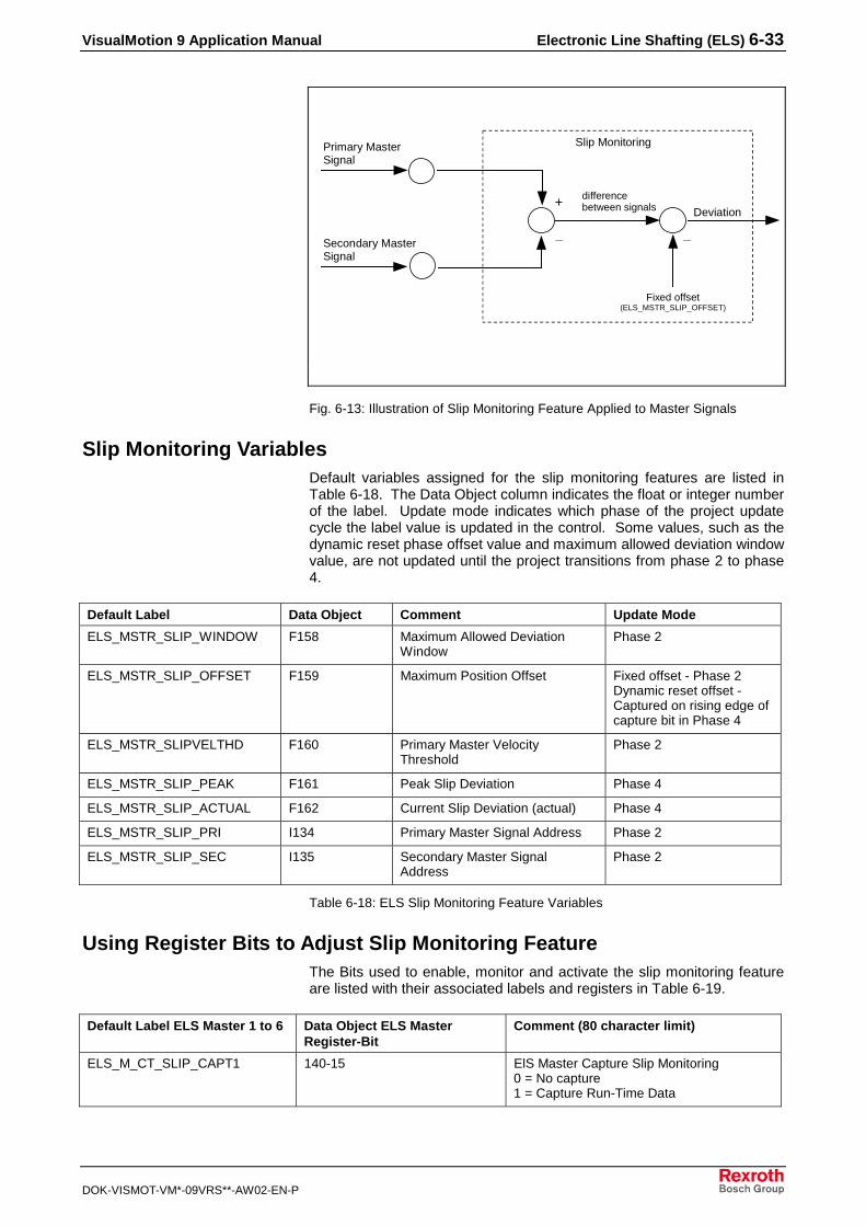
VisualMotion 9 Application Manual Electronic Line Shafting (ELS) 6-33
DOK-VISMOT-VM*-09VRS**-AW02-EN-P
_
Slip MonitoringPrimary MasterSignal
Secondary MasterSignal
+
_
Deviation
differencebetween signals
Fixed offset(ELS_MSTR_SLIP_OFFSET)
Fig. 6-13: Illustration of Slip Monitoring Feature Applied to Master Signals
Slip Monitoring VariablesDefault variables assigned for the slip monitoring features are listed inTable 6-18. The Data Object column indicates the float or integer numberof the label. Update mode indicates which phase of the project updatecycle the label value is updated in the control. Some values, such as thedynamic reset phase offset value and maximum allowed deviation windowvalue, are not updated until the project transitions from phase 2 to phase4.
Default Label Data Object Comment Update Mode
ELS_MSTR_SLIP_WINDOW F158 Maximum Allowed DeviationWindow
Phase 2
ELS_MSTR_SLIP_OFFSET F159 Maximum Position Offset Fixed offset - Phase 2Dynamic reset offset -Captured on rising edge ofcapture bit in Phase 4
ELS_MSTR_SLIPVELTHD F160 Primary Master VelocityThreshold
Phase 2
ELS_MSTR_SLIP_PEAK F161 Peak Slip Deviation Phase 4
ELS_MSTR_SLIP_ACTUAL F162 Current Slip Deviation (actual) Phase 4
ELS_MSTR_SLIP_PRI I134 Primary Master Signal Address Phase 2
ELS_MSTR_SLIP_SEC I135 Secondary Master SignalAddress
Phase 2
Table 6-18: ELS Slip Monitoring Feature Variables
Using Register Bits to Adjust Slip Monitoring FeatureThe Bits used to enable, monitor and activate the slip monitoring featureare listed with their associated labels and registers in Table 6-19.
Default Label ELS Master 1 to 6 Data Object ELS MasterRegister-Bit
Comment (80 character limit)
ELS_M_CT_SLIP_CAPT1 140-15 ElS Master Capture Slip Monitoring0 = No capture1 = Capture Run-Time Data

6-34 Electronic Line Shafting (ELS) VisualMotion 9 Application Manual
DOK-VISMOT-VM*-09VRS**-AW02-EN-P
Default Label ELS Master 1 to 6 Data Object ELS MasterRegister-Bit
Comment (80 character limit)
ELS_M_CT_SLIP_EN 140-16 ELS Master Enable Slip Monitoring0 = Off1 = On
ELS_M_ST_SLIP_ERR 141-14 ELS Master Slip Monitoring Error0 = No error1 = Error
ELS_M_ST_SLIP_ENC 141-15 ELS Master Slip Monitoring Lead Encoder0 = Primary1 = Secondary
ELS_M_ST_SLIP_ENA 141-16 ELS Master Slip Monitoring Enabled0 = Off1 = On
Table 6-19: ELS Slip Monitor Feature Default Register Bits
The slip monitoring feature is enabled with the ELS_M_CT_SLIP_EN bit.Slip monitoring is monitored by the ELS_M_ST_SLIP_ENA,ELS_M_ST_SLIP_ERR, and ELS_M_ST_SLIP_ENC bits. TheELS_M_ST_SLIP_ENA bit indicates that slip monitoring has beenenabled. The ELS_M_ST_SLIP_ERR bit indicates an excessive masterposition slip deviation error is active. To clear the error:
1. Bring the masters back in to alignment by physically moving themasters if a fixed master position offset is being used or by togglingthe ELS_M_CT_SLIP_CAPT1 bit if dynamic reset phase offset isbeing used.
2. Clear the error by toggling the ELS_M_CT_SLIP_EN bit or by togglingbit 5, CLEAR_ALL_ERRORS, of the control register.
The ELS_M_ST_SLIP_ENC monitors the encoder signals anddetermines the lead signal, which it indicates by displaying a 0 for primaryor 1 for secondary. The ELS_M_CT_SLIP_CAPT1 bit, with dynamic resetof phase offset selected, captures the slip offset of the master positions.
6.9 ELS Group
An ELS Group is a container that allows you to sectionalize a machine orprocess by grouping axes working in unison to follow a master commandsignal. The ELS Group Assignment icon allows up to eight groups to bedefined. To reference groups in the system, they are given an index from1 to 8. Each is assigned a set of control and status parameters andregisters for configuring and controlling its functionality. Basic functionsinclude; selecting a master signal to follow or internal profile, dynamicallysynchronizing to a master signal, utilizing a cam profile, applying phaseoffsets, and activating lock on/off function and jogging. The output unitsare degrees with a range between 0 and 360 degrees and the module(rollover period) fixed at 360 degrees.
When using an ELS Group to control an axis, the following considerationshould be noted:
• An axis can only be assigned to a single group. The system detectsmultiple assingments during the compile process and flags the errors.
• By default, an axis can be positioned independently of the group forsetup or other requirements using Single axis positioning or Velocitymode.
• Every time the system phases up (phase 2 to phase 4), each axis inthe group defaults to a secondary mode of operation (single axispositioning or velocity mode). You must use the ELS Mode Changeicon in the program to command the axis to follow the group masterposition.
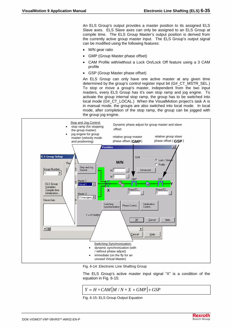
VisualMotion 9 Application Manual Electronic Line Shafting (ELS) 6-35
DOK-VISMOT-VM*-09VRS**-AW02-EN-P
An ELS Group’s output provides a master position to its assigned ELSSlave axes. ELS Slave axes can only be assigned to an ELS Group atcompile time. The ELS Group Master’s output position is derived fromthe currently active group master input. The ELS Group’s output signalcan be modified using the following features:
• M/N gear ratio
• GMP (Group Master phase offset)
• CAM Profile with/without a Lock On/Lock Off feature using a 3 CAMprofile
• GSP (Group Master phase offset)
An ELS Group can only have one active master at any given timedetermined by the group’s control register input bit (G#_CT_MSTR_SEL.)To stop or move a group’s master, independent from the two inputmasters, every ELS Group has it’s own stop ramp and jog engine. Toactivate the group internal stop ramp, the group has to be switched intolocal mode (G#_CT_LOCAL.) When the VisualMotion project’s task A isin manual mode, the groups are also switched into local mode. In localmode, after completion of the stop ramp, the group can be jogged withthe group jog engine.
Stop and Jog Control:• stop ramp (for stopping
the group master)• jog engine for group
master (velocity modeand positioning)
Switching Synchronization:• dynamic synchronization (with
/ without phase adjust)• immediate (on the fly for an
unused Virtual Master)
Dynamic phase adjust for group master and slave
offset:
relative group master relative group slave)phase offset ( GSP)
M / NH
XY
phase offset (GMP
X
M/N
Fig. 6-14: Electronic Line Shafting Group
The ELS Group’s active master input signal “X” is a condition of theequation in Fig. 6-15:
[ ] GSPGMPXNMCAMHY ++∗∗= /
Fig. 6-15: ELS Group Output Equation

6-36 Electronic Line Shafting (ELS) VisualMotion 9 Application Manual
DOK-VISMOT-VM*-09VRS**-AW02-EN-P
Where CAM[ ] is a control cam profile table or index cam profile, M and Nis the current master input/output ratio, H is a cam profile scale factor andGMP and GSP are group master and slave relative phase adjusts. Thesignal Y drives the group’s slave axes (group master position).
Note: When CAM Lock/Unlock is selected, modifications to the M/Nratio or phases P1 and P2, while the program is in phase 4,will not take affect until a transition from phase 2 to phase 4 ismade. When CAM Profile is selected, modifications to theM/N ratio or phases P1 or P2, while the program is in phase 4,will take effect immediately.
ELS Group Slave ConfigurationELS Group Slave (ELS drive)axes are assigned to an ELS Group byclicking on the Add button in the ELS Group Setup window. A maximumof 32 ELS Group Slave axes (application dependent) can be assigned toan ELS Group. All slave axes must be assigned to an ELS Group atcompile time.
els_axis_config.tif
Fig. 6-16: ELS Axis Configuration
Stop and Jog Variables, Compile Time SetupWhen an ELS Group is first configured, using the ELS Group icon, defaultvalues are supplied for:
• Stop Ramp deceleration
• Jog Controls for continuous, relative or absolute moves
These values are then saved, compiled and downloaded to the control.However, you can make modifications to any of the values for stop andjogging control using the ELS Runtime Utility.

VisualMotion 9 Application Manual Electronic Line Shafting (ELS) 6-37
DOK-VISMOT-VM*-09VRS**-AW02-EN-P
stop_and_jog.tif
Fig. 6-17: ELS Stop and Jog Variables
Jogging an ELS Group in Local ModeBefore an ELS Group can be jogged, the group must first be switched tolocal mode by toggling the G#_CT_LOCAL bit. The relative bits for jogcontrols are shaded within the ELS Group’s control register table below.
Bit # Bit Label Comment
1 G#_CT_LOCK_OFF 0=lock, 1=starts unlock
2 G#_CT_M_REL_PH 0->1 triggers master relative phase adjust
3 G#_CT_S_REL_PH 0->1 triggers slave relative phase adjust
4 G#_CT_MSTR_SEL 0=master 1, 1=master 2
5 G#_CT_VAR_CLK 0->1 forcing
6 G#_CT_LOCAL 0->1 switch to local mode (stop ramp /jogging),
1->0 switch from local mode to selectedgroup input master
7 G#_CT_JOG_INC 0=sets continuous jog mode, 1=setsincremental jog mode
8 G#_CT_JOG_ABS 0=sets relative incremental mode, 1=setsabsolute mode (then bit 7 will be ignored)
9 G#_CT_JOG_PLUS 0->1 starts jog motion in positive direction
10 G#_CT_JOG_MINS 0->1 starts jog motion in negative direction
11 G#_CT_M_ABS_PH 0->1 triggers absolute master phase adjust
12 G#_CT_S_ABS_PH 0->1 triggers absolute slave phase adjust
Table 6-20: ELS Group Control Register
Setting bit 6 high in the group control register will bring the group velocityto zero using the deceleration rate in “G#_STOP_DECEL” variable. After

6-38 Electronic Line Shafting (ELS) VisualMotion 9 Application Manual
DOK-VISMOT-VM*-09VRS**-AW02-EN-P
bit 6 (G#_ST_LOCAL) in the group status register receives anacknowledgement that the group has stopped. The group can be jogged.
The following table describes the interaction of the jog bits. In all cases,jog motion ramps to zero when “G#_CT_JOG_PLUS” and“G#_CT_JOG_MINS” are cleared, or when one bit is set and then asecond bit is set.
G#_CT_JOG_INC G#_CT_JOG_ABS G#_CT_JOG_PLUS = 0 → 1 G#_CT_JOG_MINS = 0 → 1
0 0 Continuous positive velocity. Continuous negative velocity
1 0 Moves to positive incrementaldistance of “G#_JOG_INC “variable
Moves to negative incrementaldistance of “G#_JOG_INC “variable
N/A 1 Moves in positive direction * to“G#_JOG_ABS” variable positionStatus bit “G#_ST_JOG_POS”goes high (1) when in position
Moves in negative direction * to“G#_JOG_ABS” variable positionStatus bit “G#_ST_JOG_POS”goes high (1) when in position
* shortest path is used if distance is within the “G#_JOG_WIN“ float variable
Table 6-21: Group Jogging Bit States
Switching Synchronization between Group Input MastersSwitching between ELS Group input masters 1 and 2 or local mode canbe performed using one of the following methods:
• Immediate Switching - The group's output position and velocityimmediately switches, within one SERCOS cycle, between the twomasters causing a step or bump in transition. When switching to aninactive Virtual Master, the position and velocity are adjusted “on thefly.”
• Dynamic Synchronization with or without Phase Adjust - Thevelocity and position difference will be compensated for by an internalramp function synchronizing the transition between masters.
Switching to the group’s local mode will immediately activate the group’sstop ramp. This allows stopping the group‘s output even if both groupmaster inputs are still moving. When the stop ramp has been completed,signaled by the “group local mode active bit,” the group master can bejogged. This allows moving the group master independent from the groupmaster inputs. Deactivation of the local mode will cause dynamicsynchronization / immediate switching to the active group input master.
In the following example, ELS Group 1 with master input 1 is designed tosynchronize to master input 2 when 2 is selected as the master input ofELS Group 1. In effect, master input 2 acquires the slave axes of ELSGroup 1, thus replacing 1.
Master 1
Master 2
Group Input MastersELS Group
1
Slave AxesLocal Mode
Fig. 6-18: Group Input Master Switching
When the Switching Synchronization button is selected, theSynchronization Setup window in Fig. 6-19 displays the default valuesgenerated by the ELS Group’s project variables.

VisualMotion 9 Application Manual Electronic Line Shafting (ELS) 6-39
DOK-VISMOT-VM*-09VRS**-AW02-EN-P
Synch_Setup.tif
Fig. 6-19:Synchronization Setup Window
SwitchingThis value is the maximum acceleration or deceleration that the ELSGroup will use to ramp up to the new master’s velocity and perform anyphase corrections with a trapezoidal velocity profile.
Note: The maximum acceleration and deceleration value is onlyused for dynamic synchronization.
This selection determines the method for switching between ELS Groupinput masters, immediate switching or dynamic synchronization.
Note: Phase correction is only available for dynamic synchronization.
Phase CorrectionSpecifies the direction in which the phase correction will be made. Theuser can select shortest path, positive, negative or no phasecorrection.
Specifies the maximum increase or decrease in velocity allowed formatching the phase (position) of a target master.
When selecting a positive or negative direction, the value (± 0-180degrees) entered creates a range (monitoring window) around theposition of the target master. If any phase errors are within this window,the shortest path will be used for the correction. This allows large phasecorrections to be eliminated depending on the size of the window.
When this option is selected, you can apply smoothing to your ELS groupprofile. If this is not selected, the default trapezoidal profile will beapplied.
Maximum accel/decel fordynamic sync.
Switching type:
Correction type
Maximum additive velocity
Maximum phase differenceallowed for shortest path
correction
Enable jerk limiting forramp/lock modes and master
velocity changes
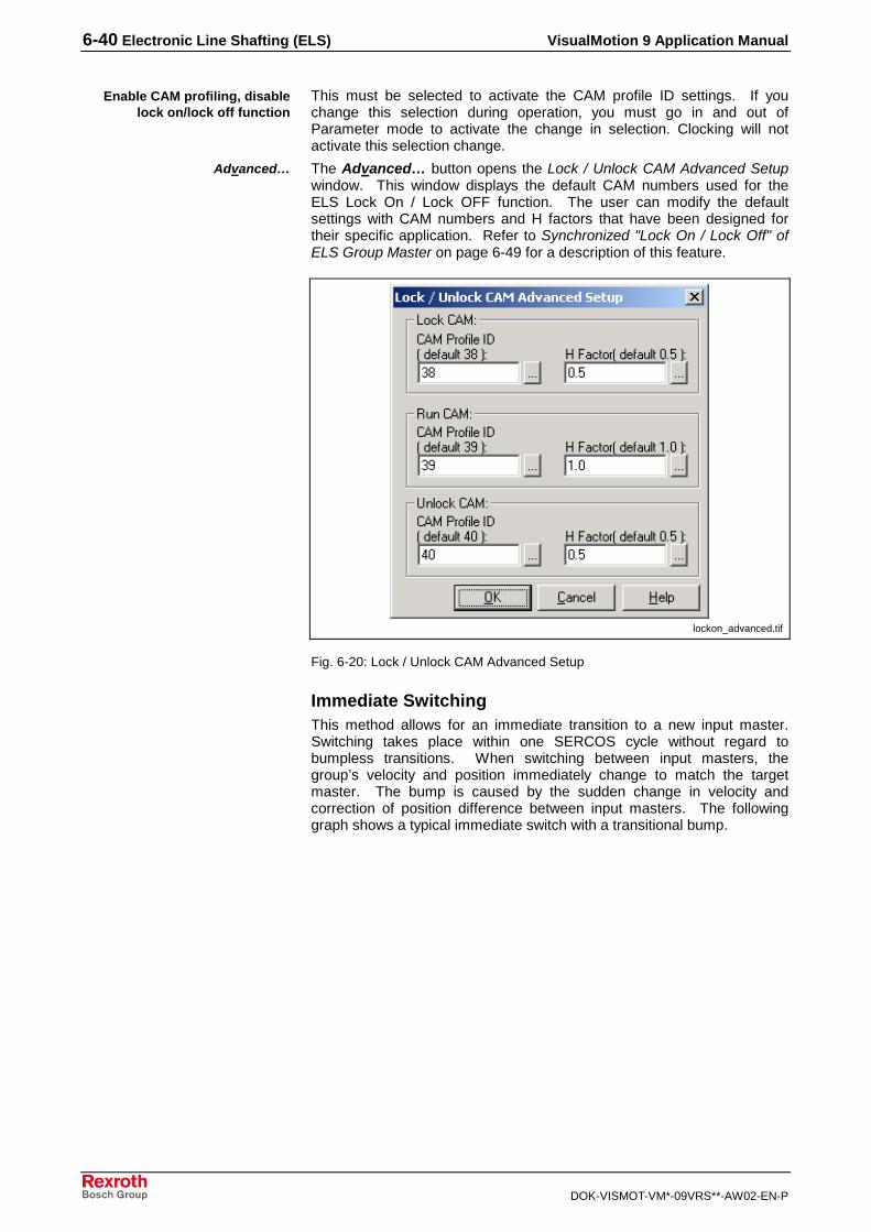
6-40 Electronic Line Shafting (ELS) VisualMotion 9 Application Manual
DOK-VISMOT-VM*-09VRS**-AW02-EN-P
This must be selected to activate the CAM profile ID settings. If youchange this selection during operation, you must go in and out ofParameter mode to activate the change in selection. Clocking will notactivate this selection change.
The Advanced… button opens the Lock / Unlock CAM Advanced Setupwindow. This window displays the default CAM numbers used for theELS Lock On / Lock OFF function. The user can modify the defaultsettings with CAM numbers and H factors that have been designed fortheir specific application. Refer to Synchronized "Lock On / Lock Off" ofELS Group Master on page 6-49 for a description of this feature.
lockon_advanced.tif
Fig. 6-20: Lock / Unlock CAM Advanced Setup
Immediate SwitchingThis method allows for an immediate transition to a new input master.Switching takes place within one SERCOS cycle without regard tobumpless transitions. When switching between input masters, thegroup’s velocity and position immediately change to match the targetmaster. The bump is caused by the sudden change in velocity andcorrection of position difference between input masters. The followinggraph shows a typical immediate switch with a transitional bump.
Enable CAM profiling, disablelock on/lock off function
Advanced…

VisualMotion 9 Application Manual Electronic Line Shafting (ELS) 6-41
DOK-VISMOT-VM*-09VRS**-AW02-EN-P
Virtual Master 1(active and running)
ELS Group 1 velocity followsVirtual Master 1
Immediate Switchingfrom
Virtual Master 1 to Virtual Master 2
ELS Group 1 position followsVirtual Master 1
Virtual Master 1velocity is constantin this example.
VirtualMaster 1
VirtualMaster 2
ELS Group 1
ELS Group 2
Input 1
Input 2
Input 1
Input 2
Slaveaxis
Slaveaxis
VirtualMaster 1
VirtualMaster 2
ELS Group 1
ELS Group 2
Input 1
Input 2
Input 1
Input 2
Slaveaxis
Slaveaxis
Before Immediate Switching After Immediate Switching
ELS Group 1
Virtual Master 2velocity is greaterthan the velocity ofVirtual Master 1.
Virtual Master 2(active and running)
ELS Group 1velocity
ELS Group 1 position immediately switchesto match Virtual Master 2 position
ELS Group 1 velocity immediately switchesto match Virtual Master 2 velocity
Bump
Bump
360°
360°
360°
0°
0°
0°
0
ELS Group 1 settings for this example are as follows:1:1 CAM, M/N ratio =1, relative group phase offsets = 0
Fig. 6-21: Immediate Switching of ELS Group 1
Immediate Switching to an Inactive Virtual Master(also known as “On the Fly” Switching)A special case of immediate transition called “On the Fly” applies only toVirtual Masters that are not connected to any groups. On the Fly is animmediate, bumpless transition achieved by initializing the virtual master’sposition and velocity with a sampling of the group’s current position andvelocity. This transition is only possible when the following conditionsexist:
• The Fast Stop bit (VM#_CT_FSTOP) is not active
• The Go bit (VM#_CT_GO) is high
• The Virtual Master is in velocity mode (VM#_CT_VMODE bit is high)

6-42 Electronic Line Shafting (ELS) VisualMotion 9 Application Manual
DOK-VISMOT-VM*-09VRS**-AW02-EN-P
Note: It is not possible to use this method to synchronize to a RealMaster since instantaneous changes in position, velocity, oracceleration would result in a drive fault.
Immediate “On the Fly” Switchingfrom
Virtual Master 1 to Virtual Master 2
Virtual Master 1velocity is constant inthis example
VirtualMaster 1
VirtualMaster 2
ELS Group 1
Input 1
Input 2
Slaveaxis
VirtualMaster 1
VirtualMaster 2
ELS Group 1
Input 1
Input 2
Slaveaxis
Before Immediate Switching After Immediate Switching
Virtual Master 1(active and running)
Virtual Master 2 (active)shown in this example atstandstill before switching Control bit settings for Virtual Master 2:
VM#_CT_FSTOP = 0VM#_CT_GO = 1VM#_CT_VMODE = 1
Virtual Master 2 switches"On the Fly" and acquiresthe position and velocity ofthe master* used at input 1
ELS Group 1 position isnot affected by immediateswitch to Virtual Master 2position (bumpless)
ELS Group 1 position followsVirtual Master 1
ELS Group 1 position nowfollows Virtual Master 2
ELS Group 1 velocity isnot affected by immediateswitch to Virtual Master 2
360°
360°
360°
0°
0°
0°
0
* master used for input 1 can be a Virtual or Real Master
Fig. 6-22: Immediate “On the Fly“ Switching of ELS Group 1

VisualMotion 9 Application Manual Electronic Line Shafting (ELS) 6-43
DOK-VISMOT-VM*-09VRS**-AW02-EN-P
Dynamic SynchronizationTypically, this general-purpose method synchronizes an ELS Group with areal, virtual or ELS Group Master to another real, virtual or ELS GroupMaster.
Master 1(active and running)
Dynamic Switchingfrom
Master 1 to Master 2
Phase correction necessaryto match target master(performed after velocitiesare matched)
ELS Group 1 position followsMaster 1
Master 1
Master 2
ELS Group 1
ELS Group 2
Input 1
Input 2
Input 1
Input 2
Slaveaxis
Slaveaxis
Master 1
Master 2
ELS Group 1
ELS Group 2
Input 1
Input 2
Input 1
Input 2
Slaveaxis
Slaveaxis
Before Dynamic Switching After Dynamic Switching
Velocity of ELS Group 1 firstmatches the velocity of VirtualMaster 2 before a phasecorrection is performed.
Master 2(active and running)
ELS Group 1
ELS Group 1velocity
Master 1 velocity isconstant in thisexample
Master 2 velocity isconstant in thisexample
Phasedifference
ELS Group 1 positionmatches target masterposition after executinga phase correction
360°
360°
360°
0°
0°
0°
0
Fig. 6-23: Dynamic Switching of ELS Group 1
Dynamic synchronization allows for a rapid switch to a temporary(internal) velocity mode Virtual Master which then ramps and locks ontothe new target master. The temporary master immediately disconnectsthe group’s connection to the first master and allows for a smoothtransition to the next master. Ramping is performed using the ELS Groupsynchronization's acceleration and velocity rates. These rates are alsoused for dynamic group master and slave phase corrections.
After ramping (velocity synchronization), a phase adjust compensates forany position error. Once the phase adjust is complete, the ELS Group’s

6-44 Electronic Line Shafting (ELS) VisualMotion 9 Application Manual
DOK-VISMOT-VM*-09VRS**-AW02-EN-P
master is switched to the new input master. The temporary, internalmaster is dissolved after the transition is complete.
Note: Any attempt to switch masters again during dynamicsynchronization is ignored, with the exception of switching tolocal mode (stop ramp).
Switching Synchronization with Advanced TriggerOptionsSwitching Synchronization between masters can be controlled to agreater extent with the Advanced trigger options feature in theSynchronization Setup window, see Fig. 6-24. The advanced triggerfeature includes settings to specify when switching occurs. It sets up atwo-step process to the to the switching. The first step is the SwitchingTrigger which determines exactly when the switching is to start (Advancedtrigger feature) and the second step is the Switching Type (standardswitching feature) which determines exactly how the switching isperformed.
Synch_Setup_Adv.tif
Fig. 6-24: Synchronization Setup with Advanced Trigger Options
Four types of switching triggers can be used for group switching to theMaster 1 or Master 2 signal:
• Instantaneous – Disables the switching trigger functionality.
• Master 1 Position – Starts switching when group master 1 haspassed a specific trigger position.
• Master 2 Position – Starts switching when group master 2 haspassed a specific trigger position.
• Optimal – Starts switching when a certain relationship between thegroup masters occurs, for example, when the group‘s masterpositions coincide or when the group’s constant acceleration rampresults in synchronization to the target master’s position and velocitysimultaneously.

VisualMotion 9 Application Manual Electronic Line Shafting (ELS) 6-45
DOK-VISMOT-VM*-09VRS**-AW02-EN-P
Note: The position trigger used is independent of which master thegroup is switched to. For example, the Master 1 positionswitching trigger can be used when switching to group master1 or 2.
The following Diagrams illustrate the group master switching exampleswith triggering mechanisms. These methods are used in VisualMotion 9software. Switching triggers make it possible to start the actual masterswitching process when a certain condition is met. The master 1 positionand master 2 position switching triggers start the switching process whenone of the group masters has met a specific trigger condition.
Immediate Switching Using the Master 1 and 2 SwitchingTriggersThe immediate switching trigger disables the switching trigger functionalityso the master switch will begin as soon as the group’s control register bitis transitioned.
Virtual Master 1(active and running)
ELS Group 1 velocityfollows Virtual Master 1
Immediate Switching from VirtualMaster 1 to Virtual Master 2
using Master 1 Position Trigger
ELS Group 1 positionfollows Virtual Master 1
Virtual Master 1velocity is constantin this example.
ELS Group 1
Virtual Master 2velocity is greaterthan the velocity ofVirtual Master 1.
Virtual Master 2(active and running)
ELS Group 1velocity
ELS Group 1 position immediately switchesto match Virtual Master 2 position
ELS Group 1 velocity immediately switchesto match Virtual Master 2 velocity
Bump
Bump
360°
360°
360°
0°
0°
0°
0
Master Switch Requested(Switching Trigger Armed)
Master Switch Triggered WhenVirtual Master 1 Passes 72°
Virtual Master 1Passes 72°
Fig. 6-25: Immediate Switching Using the Master 1 and 2 Switching Triggers

6-46 Electronic Line Shafting (ELS) VisualMotion 9 Application Manual
DOK-VISMOT-VM*-09VRS**-AW02-EN-P
Immediate Switching using Optimal Switching TriggerThis master switch is triggered when the master positions are equal. Assoon as the two masters reach the same position, the group matches thevelocity of the target master. Switching is dependent on how long it takesuntil the masters to reach the same position.
Note: If the velocity of the master is equal to the velocity of thegroup, switching will not occur until the master 1 velocitychanges.
Virtual Master 1(active and running)
ELS Group 1 velocityfollows Virtual Master 1
Immediate Switching from VirtualMaster 1 to Virtual Master 2 using
the Master 1 Position Trigger
ELS Group 1 positionfollows Virtual Master 1
Virtual Master 1velocity is constantin this example.
ELS Group 1
Virtual Master 2velocity is greaterthan the velocity ofVirtual Master 1.
Virtual Master 2(active and running)
ELS Group 1velocity
ELS Group 1 position immediately switchesto match Virtual Master 2 position
ELS Group 1 velocity immediately switchesto match Virtual Master 2 velocity
Bump
360°
360°
360°
0°
0°
0°
0
Master Switch Requested(Switching Trigger Armed)
Master Switch Triggered When theVirtual Master Positions are Equal
Virtual MasterPositions areEqual
Immed_Optimal_Switch.tif
Fig. 6-26: Immediate Switching using the Optimal Switching Trigger

VisualMotion 9 Application Manual Electronic Line Shafting (ELS) 6-47
DOK-VISMOT-VM*-09VRS**-AW02-EN-P
Immediate “On the Fly” Switching using Master 1 and 2Switching TriggerMaster 2 is a virtual master that is active, but in standby mode until themaster switch is triggered. Once the switch is triggered, master 2switches on the fly and acquires the position and velocity of master 1.The ELS group switches from master 1 to master 2 when master 2 is atthe same position and velocity as master 1, producing a bumpless grouptransition.
Immediate “On the Fly” Switching fromVirtual Master 1 to Virtual Master 2 usingthe Master 1 Position Switching Trigger
Virtual Master 1velocity is constant inthis example
Virtual Master 1(active and running)
Virtual Master 2 (active,but unused) shown in thisexample at standstillbefore switching
Virtual Master 2 switches"On the Fly" and acquiresthe position and velocity ofthe master* used at input 1
ELS Group 1 position isnot affected by immediateswitch to Virtual Master 2position (bumpless)
ELS Group 1 positionfollows Virtual Master 1
ELS Group 1 position nowfollows Virtual Master 2
ELS Group 1 velocity isnot affected by immediateswitch to Virtual Master 2
360°
360°
360°
0°
0°
0°
* master used for input 1 can be a Virtual or Real Master
ELS Group 1
ELS Group 1velocity
0
Master Switch Requested(Switching Trigger Armed)
Master Switch Triggered WhenVirtual Master 1 Passes 72°
Virtual Master 1Passes 72°
Immed_On_Fly_Mstr_Switch.tif
Fig. 6-27: Master 1 and 2 Immediate “on the Fly” Switching
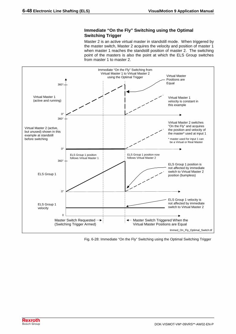
6-48 Electronic Line Shafting (ELS) VisualMotion 9 Application Manual
DOK-VISMOT-VM*-09VRS**-AW02-EN-P
Immediate “On the Fly” Switching using the OptimalSwitching TriggerMaster 2 is an active virtual master in standstill mode. When triggered bythe master switch, Master 2 acquires the velocity and position of master 1when master 1 reaches the standstill position of master 2. The switchingpoint of the masters is also the point at which the ELS Group switchesfrom master 1 to master 2.
Immediate “On the Fly” Switching fromVirtual Master 1 to Virtual Master 2
using the Optimal Trigger
Virtual Master 1velocity is constant inthis example
Virtual Master 1(active and running)
Virtual Master 2 (active,but unused) shown in thisexample at standstillbefore switching
Virtual Master 2 switches"On the Fly" and acquiresthe position and velocity ofthe master* used at input 1
ELS Group 1 position isnot affected by immediateswitch to Virtual Master 2position (bumpless)
ELS Group 1 positionfollows Virtual Master 1
ELS Group 1 position nowfollows Virtual Master 2
ELS Group 1 velocity isnot affected by immediateswitch to Virtual Master 2
360°
360°
360°
0°
0°
0°
* master used for input 1 can be a Virtual or Real Master
ELS Group 1
ELS Group 1velocity
0
Master Switch Requested(Switching Trigger Armed)
Virtual MasterPositions areEqual
Master Switch Triggered When theVirtual Master Positions are Equal
Immed_On_Fly_Optimal_Switch.tif
Fig. 6-28: Immediate “On the Fly” Switching using the Optimal Switching Trigger

VisualMotion 9 Application Manual Electronic Line Shafting (ELS) 6-49
DOK-VISMOT-VM*-09VRS**-AW02-EN-P
Dynamic Switching using Master 1 and 2 Switching TriggerBoth master 1 and master 2 remain at a constant velocity. The ELSGroup follows master 1 until the master switch triggers the group to switchto master 2. When the group is triggered, it ramps speed, eitheraccelerating or decelerating until it reaches the target position at whichpoint it will be close to the velocity of the master two. At the point ofswitching, the group will experience a minor phase adjustment to matchmaster 2.
Master 1(active and running)
Dynamic Switching fromMaster 1 to Master 2 using
the Master 2 Position Trigger
Phase correction necessaryto match target master(performed after velocitiesare matched)
ELS Group 1 position followsMaster 1
Velocity of ELS Group 1 firstmatches the velocity of VirtualMaster 2 before a phasecorrection is performed.
Master 2(active and running)
ELS Group 1
ELS Group 1velocity
Master 1 velocity isconstant in thisexample
Master 2 velocity isconstant in thisexample
ELS Group 1 positionmatches target masterposition after executinga phase correction
360°
360°
360°
0°
0°
0°
0
Master Switch Requested(Switching Trigger Armed)
Master Switch Triggered WhenVirtual Master 2 Passes 20°
Virtual Master 2Passes 20°
Dynam_Mstr_Switch.tif
Fig. 6-29: Dynamic Switching using Master 1 and 2 Switching Trigger

6-50 Electronic Line Shafting (ELS) VisualMotion 9 Application Manual
DOK-VISMOT-VM*-09VRS**-AW02-EN-P
Dynamic Switching using Optimal TriggerMaster 1 and 2 maintain their velocities and positions. The master switchtriggers the ELS group to switch to target master. The project calculateswhen the group should begin changing velocity to match the velocity ofmaster 2. When the ELS group’s constant acceleration ramp will result ina merge with the target master’s position and velocity, the master switchtriggers ELS group to switch to the target master. After the ELS grouphas switched to the target master, a slight phase correction, of up to twoSERCOS cycles of the closing velocity of the two masters, may benecessary to exactly match the target master.
Note: Changes in the velocity of either group master duringOptimized Dynamic Synchronization
Master 1(active and running)
Dynamic Switching fromMaster 1 to Master 2 using
the Optimal Trigger
Constant-acceleration rampsynchs group with master2’s position and velocitynearly simultaneously.
ELS Group 1 position followsMaster 1
Constant-acceleration ramp totarget master’s velocity.
Master 2(active and running)
ELS Group 1
ELS Group 1velocity
Master 1 velocity isconstant in thisexample
Master 2 velocity isconstant in thisexample
ELS Group 1 positionmatches target masterposition after a minorphase correction.
360°
360°
360°
0°
0°
0°
0
Master Switch Requested(Switching Trigger Armed)
Master switch triggered when thegroup’s constant-acceleration rampwill result in it merging with thetarget master’s position and velocitynearly simultaneously.
Minor phase correctionafter ramp completes.
Dynam_Mstr_Switch.tif
Fig. 6-30: Dynamic Switching Using Optimal Trigger
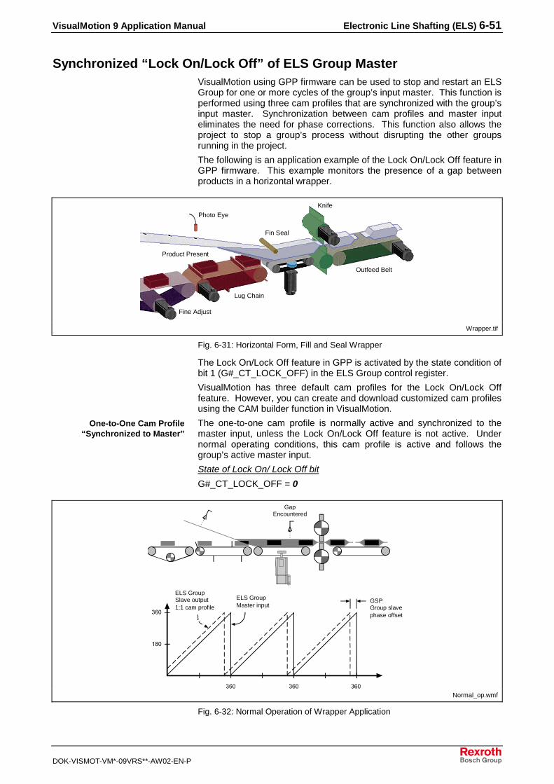
VisualMotion 9 Application Manual Electronic Line Shafting (ELS) 6-51
DOK-VISMOT-VM*-09VRS**-AW02-EN-P
Synchronized “Lock On/Lock Off” of ELS Group MasterVisualMotion using GPP firmware can be used to stop and restart an ELSGroup for one or more cycles of the group’s input master. This function isperformed using three cam profiles that are synchronized with the group’sinput master. Synchronization between cam profiles and master inputeliminates the need for phase corrections. This function also allows theproject to stop a group’s process without disrupting the other groupsrunning in the project.
The following is an application example of the Lock On/Lock Off feature inGPP firmware. This example monitors the presence of a gap betweenproducts in a horizontal wrapper.
Photo Eye
Fin Seal
Knife
Outfeed Belt
Lug Chain
Fine Adjust
Product Present
Wrapper.tif
Fig. 6-31: Horizontal Form, Fill and Seal Wrapper
The Lock On/Lock Off feature in GPP is activated by the state condition ofbit 1 (G#_CT_LOCK_OFF) in the ELS Group control register.
VisualMotion has three default cam profiles for the Lock On/Lock Offfeature. However, you can create and download customized cam profilesusing the CAM builder function in VisualMotion.
The one-to-one cam profile is normally active and synchronized to themaster input, unless the Lock On/Lock Off feature is not active. Undernormal operating conditions, this cam profile is active and follows thegroup’s active master input.
State of Lock On/ Lock Off bit
G#_CT_LOCK_OFF = 0
ELS GroupSlave output1:1 cam profile
ELS GroupMaster input
GSPGroup slavephase offset
GapEncountered
Normal_op.wmf
Fig. 6-32: Normal Operation of Wrapper Application
One-to-One Cam Profile“Synchronized to Master”

6-52 Electronic Line Shafting (ELS) VisualMotion 9 Application Manual
DOK-VISMOT-VM*-09VRS**-AW02-EN-P
The Lock Off cam profiledecelerates to a stop over one cycle of themaster. After this cycle, the group's velocity is stopped and will not restartunless the LOCK OFF bit is toggled.
Note: All motion to the ELS Group Master, as well as any cascadinggroups, will stop.
State of Lock On/Lock Off bit
G#_CT_LOCK_OFF = 0 to 1
No GAPDetected Knife follows lock off
cam profile
Lock Off cam activeafter internal camtable 360° rollover
No GAPDetectedLock off bit = 1
GSP
Lock Off cam activeuntil:Lock off bit = 0
No_product.wmf
Fig. 6-33: Lock Off Cam Active, No Product - No Seal
The Lock On cam profile is active and accelerates from a stoppedposition to match the velocity of the master input over one cycle of themaster (360 degrees). After this cycle, the velocity of the group matchesthat of the master.
State of Lock On/Lock Off bit
G#_CT_LOCK_OFF = 1 to 0
GAP Detectedagain
Knife returns tonormal operation
Lock On cam activeafter internal camtable 360° rollover
GAP Detectedagain:Lock off bit = 0
GSP
Lock On cam 1:1 cam profile
Product.WMF
Fig. 6-34: Lock On Cam Active, Product is Present Once Again
Lock Off
Lock On

VisualMotion 9 Application Manual Electronic Line Shafting (ELS) 6-53
DOK-VISMOT-VM*-09VRS**-AW02-EN-P
Phase ControlThe group master and slave phase adjust defaults to a trapezoidalvelocity profile using:
• dynamic synchronization acceleration
• dynamic synchronization velocity
Relative phase adjusts are written to the following ELS Group floatvariables
• G#_REL_M_PH (group master relative master phase adjust)
• G#_REL_S_PH (group master relative slave phase adjust)
and triggered with bit 2 or 3 in the ELS group control register. Afterexecution of the velocity profile, the absolute group master or group slavephase adjust is updated. The phase adjust can also be configured toexecute in one step by selecting Immediate in the Phase window.
Phase_Control.tif
Fig. 6-35: Phase Control
The absolute group master and group slave phase adjust is triggered by a0 → 1 bit transition. The bit goes to 1 at the start of the phase adjust andto 0 when the phase adjust is complete. The direction of the move isdependent on the settings of the ELS Group Configuration:
Bit 11: Group Master Absolute Phase Adjust
Bit 7 Bit 6 Description
0 0 Shortest path
0 1 Positive phase lock, if phase difference is greater thanG#_LOCK_WIN, or use shortest path
1 0 Negative phase lock, if phase difference is greater thanG#_LOCK_WIN, or use shortest path
1 1 Phase lock disabled (provides velocity synchronizationonly)

6-54 Electronic Line Shafting (ELS) VisualMotion 9 Application Manual
DOK-VISMOT-VM*-09VRS**-AW02-EN-P
Bit 12: Group Slave Absolute Phase Adjust
Bit 7 Bit 6 Description
0 0 Shortest path
0 1 Positive phase lock, if phase difference is greater thanG#_LOCK_WIN, or use shortest path
1 0 Negative phase lock, if phase difference is greater thanG#_LOCK_WIN, or use shortest path
1 1 Phase lock disabled (provides velocity synchronizationonly)
The absolute phase adjust values can only be read except when the stopramp is active and the group master is at standstill. In this case theabsolute phase adjust values can be overwritten and forced.
If an ELS group is switched to local, manual or parameter mode during aphase adjust with a trapezoidal velocity profile, the phase adjust will becompleted.
Initialization ControlThe Initialization window is used to configure the ELS group masteroperation during project initialization. The configuration set in this windowis set in parameter mode.
This can be set at automatic or you can switch the group switch the ELSgroup to the master manually. The group will remain in local mode whenthe project comes out of parameter mode until it is manually switched.
Init_Control.tif
Fig. 6-36: Initialization Control
During phase 2 of power up, you can select to use either old values orone of the following:
• the variables initialized by the internal group master being set to thevalue of the active group input master
• the cam table input position set to the internal group input masterposition plus the group master offset
• the state of the state machine set to 1
• the old values kept for absolute master and group slave offset
• the ELS group master position calculated with the cam equation
Sync to ELS Group master ontask switching from Manual to
Automatic Mode
ELS Group master positionsinitialization at Phase 2

VisualMotion 9 Application Manual Electronic Line Shafting (ELS) 6-55
DOK-VISMOT-VM*-09VRS**-AW02-EN-P
In phase 4 of power up, the ELS group can be reinitialized when the localmode is active and the ELS group master is at standstill(G#_ST_MOTION is 0). Under these conditions, the following variablesare not updated by the control and can be overwritten:
• Internal group input master position
• Group cam table input position (used to calculate the ELS groupmaster position)
• ELS group master position (only when bit 9 in the ELS configurationword is set to 1)
• State of the state machine for lock on/lock off (used to calculate theELS group master position)
• Aboslute group master and group slave offset (used to calculate theELS group master position)
You can select to use the old values and no calculation of the camequation will be performed or you can select the Group master position tobe calculated. The Group master is calculated using the group cam tableinput position, the absolute group master and group slave offset, and theselected state of the state machine.
The default setting of 180 degrees matches the default profile inVisualMotion. This number can be changed, but the lock on/lock offprofile must be completed in 1 revolution of the master cycle.
6.10 Editing ELS Groups and System Masters Online
The ELS Runtime Utility in VisualMotion GPP can be used to change thesettings of the ELS System Masters, ELS Groups and Virtual Masterswhile the project is online. These changes only effect the data in thecontrol and are maintained in the control when the project goes offline. Ifthe project is synchronized, the changes made using the Runtime Utilityare overwritten with the settings in the project.
To select a group or master to edit, use the drop-down menu in the ELSRuntime Tool window. When one of the menu items has been selected, abutton for that item will appear in the window. Clicking the button willopen a window for configuring that group or master.
ELS_Runtime_Tool.tif
Fig. 6-37: ELS Runtime Tool
The association of the ELS System master to its number in theconnection box can be changed by selecting this option in the ELSRuntime Utility. The ELS System Masters can be edited by selecting the
ELS Group master positionsevaluation with forcing
Lock On Offset

6-56 Electronic Line Shafting (ELS) VisualMotion 9 Application Manual
DOK-VISMOT-VM*-09VRS**-AW02-EN-P
Master number tab which corresponds to the Connection box designationfor that master, see Fig. 6-38.
ELS_Runtime_Utility.tif
Fig. 6-38: Edit ELS System Masters Window
Changes made in the runtime utility take effect immediately in the controlwhen you click the OK button.

VisualMotion 9 Application Manual Program Debugging and Monitoring 7-1
DOK-VISMOT-VM*-09VRS**-AW02-EN-P
7 Program Debugging and Monitoring
7.1 Finding Program Problems
Identifying errors in complex programs can be difficult. A thoroughunderstanding of your application and a project designed around theapplication will help minimize the difficulty in locating errors. A practicalapproach to designing a project is to begin with simple, basic programblocks. Test the blocks, independently if possible, even if testing requireswriting additional program just for test purposes. A tested anddependable section of a program allows you to focus on just the potentialproblem areas. If the program compiles correctly, make sure that theproblem lies with the program, not the hardware. If necessary, write shorttest programs to test individual hardware functions.
Use a program branch and the VisualMotion’s message capabilities toinsert a message into your program. Shortly stopping the program andchecking critical values can tell you where errors are occurring.
Think through the implications of using triggered events. Remember thatevents and the execution of event functions typically occurasynchronously to program tasks. You cannot always depend on thetiming of triggered events. It may be necessary to add additional programcode to provide synchronization.
The following Task parameters can also be used to help with programdebugging:
• T-0-0130 Current Instruction Pointer
• T-0-0131 Current Instruction
• T-0-0132 Instruction Pointer at Error
• T-0-0133 Composite Instruction Pointer
• T-0-0135 Current Subroutine
• T-0-0136 Stack Variable Data
• T-0-0137 Task Subroutine Breakpoint
• T-0-0138 Sequencer Information
• T-0-0200 Last Active Event Number
If the program does not compile, or compiles with errors, useVisualMotion's "Display Code" selection from the Build menu to checkthat the compiler is generating the instructions you intend. Rememberthat the compiler doesn't check your program's logic, the compiler canonly check for proper syntax and use. VisualMotion's compilers typicallyprovide error or warning dialog windows that refer to line numbers in thedisplayed code. The following section provides the syntax of thedisplayed code.
Test CodeA typical example of additional code for testing program functionality isthe use of counters. One way to implement a counter would be to changethe state of an I/O bit after a distance event has occurred. After eachmove that is suppose to trigger the event, increment an integer variablecalled “move_count.” Then, use a branch statement to test whether theI/O bit changed state. If it did, then increment an integer variable called“event_count.” The final value of “event_count” can be compared to“move_count” to see if the event occurred once for every move.

7-2 Program Debugging and Monitoring VisualMotion 9 Application Manual
DOK-VISMOT-VM*-09VRS**-AW02-EN-P
7.2 Control Compiler Base Code
Compiling an Icon or Text Language program produces a text file outputlisting in Control Base Code, using mnemonics and syntax similar toassembly language. The Base Code resulting from the compilation of aprogram may be viewed using Window's Notepad by selecting "DisplayCode" from the VisualMotion Build menu. Base Code may also beviewed using a compatible ASCII-only text editor.
Base Code is typically used as an aid to debugging when checking aprogram for logical errors. Base Code files are view-only program listingfiles. Editing a Base Code file has no effect on a subsequent re-compilation of the program.
The labels in a Base Code listing result from both user-defined labels andthe labels that are generated internally by the VisualMotion compiler.
Base Code instruction mnemonics and valid argumentsThis section lists Base Code instruction mnemonics and valid arguments.Instructions requiring more than one argument show the argumentsseparated by commas. Alternative forms for arguments are shown byenclosing a general form for each argument in square brackets,separated by a vertical bar "|".
ABORT_PATHABORT_PATH [task]Halts coordinated motion in the specified task.
ACCELACCEL [axis | label | Ix | GIx],[rate | label | Fx | Gfx]
Sets the acceleration rate for the specified axis.
AXESAXES task mode, axis,
Specifies the axes to be assigned to this task and how they will be used.(All axes used in a task must be declared for that task.)
Task mode:
1. for single axis non-coordinated motion.
2. for coordinated axis for multi-axis coordinated motion.
3. for velocity mode, rotation only - no axis positioning.
4. for ratioed slave axis.
5. for ELS mode.
6. for Torque mode.
Axis = a valid identifier for an axis, from 1 to the maximum number ofaxes
AXES_GROUPAXES_GROUP task mode, axis, axis, axis, axis, axis, axis
AXIS_EVENTAXIS_EVENT [axis | label | Ix | GIx], event #1, event #2, event #3, event#4
Enables up to four Repeating Position events for a single-axis, ELS, ratio,or velocity mode axis.
Event # = [an integer Event # | label | Ix | GIx]

VisualMotion 9 Application Manual Program Debugging and Monitoring 7-3
DOK-VISMOT-VM*-09VRS**-AW02-EN-P
AXIS_ATPOSITIONAXIS_ATPOSITION axis, position
where
Axis = drive number
Position = position to wait for
AXIS_WAITAXIS_WAIT [axis | label | Ix | Gix]
If the argument is a positive integer representing a valid axis, programexecution waits for the axis to be within its preset drive position window.If the argument is -1, program execution waits until all axes in the task arewithin their position windows. The position window is defined by the driveparameters: Position Window and Zero Velocity. AXIS_WAIT will waitindefinitely if used with velocity mode (axis task mode 3) since positioningis not used.
BNEBNE label (subroutine or event)
Branches to label if the task's status word is set to "not equal.”
BEQBEQ label (subroutine or event)
Branches to label if the task's status word is set to "equal.”
BGTBGT label (subroutine or event)
Branches to label if the task's status word is set to "greater than.”
BLTBLT label (subroutine or event)
Branches to label if the task's status word is set to "less than.”
BGEBGE label (subroutine or event)
Branches to label if the task's status word is set to "greater than or equal.”
BLEBLE label (subroutine or event)
Branches to label if the task's status word is set to "less than or equal.”
BRABRA label (subroutine or event)
Branch to label, always (no matter what)
CALL_FUNCCALL_FUNC func_offset, ret_pointer, arg_count, arg1_ptr, ... argn_ptr
Calls the function at func_offset with a return pointer and a variablenumber of arguments.
func_offset offset in bytes from current program counter to start of function
ret_pointer pointer to int or float return variable
if (0), there is no return value

7-4 Program Debugging and Monitoring VisualMotion 9 Application Manual
DOK-VISMOT-VM*-09VRS**-AW02-EN-P
arg_count number of arguments passed to the function
if (0), there are no arguments
there can be between 1 and 5 arguments
arg1_ptr... argn_ptr pointer to argument passed to function
can be int, float, global int, global float, constant int, constant float, local int, localfloat,
absolute or relative point label
used as initial value of local variable
CALCCALC evaluates the equation
CAP_ENABLECAP_ENABLE axis, probe, event#
Enables the event on the axis for the probe transition. When thetransition occurs, the event triggers.
Axis = from 1 to the maximum number of axes
Probe:1 = probe 1, 0 --> 1
2 = probe 1, 1 --> 0
3 = probe 2, 0 --> 1
4 = probe 2, 1 --> 0
Event = [event # | label | Ix | GIx]
CAP_SETUPCAP_SETUP axis, probe
At program activation, the drive is configured to capture feedback positionon its probe transition and to include position data in its cyclic telegramdata.
Axis = from 1 to the maximum number of axes
Probe:1 = probe 1, 0 --> 1
2 = probe 1, 1 --> 0
3 = probe 2, 0 --> 1
4 = probe 2, 1 --> 0
CLEARCLEAR [Ix | GIx | Fx | GFx | label]
Sets integer or float variable to zero
COMPCOMP [Ix | GIx | Fx | GFx | label], [Ix | GIx | Fx | GFx | label]
Set the task's status word to the logical result of 1st argument minus 2ndargument.
DATA_SIZEDATA_SIZE I, F, ABS, REL, EVT, ZONE
Sets the amount of memory allocated for each type of data in one of thefour program tasks. (The total program requirement is the sum of theDATA_SIZE allocations for each task in the program.)

VisualMotion 9 Application Manual Program Debugging and Monitoring 7-5
DOK-VISMOT-VM*-09VRS**-AW02-EN-P
I = the number of integer variables allocated for this task
F = the number of floating point variables allocated for this task
ABS = the number of absolute point table entries allocated for this task
REL = the number of relative point table entries allocated for this task
EVT = the number of event table entries allocated for this task
ZONE = the number of zone table entries allocated for this task
DECDEC [Ix | GIx | label]
Subtracts 1 from the specified integer variable
DECELDECEL axis, rate
Sets the deceleration rate for the axis
Axis = [integer constant | label | Ix | GIx]
Rate = [floating point constant | label | Fx | GFx]
ELS_ADJUSTELS_ADJUST axis, offset
Sets the phase or velocity offset for the ELS axis.
Axis = [integer constant | label | Ix | GIx]
Offset = [floating point constant | label | Fx | GFx]
ELS_ADJUST1ELS_ADJUST1 axis, offset, type
Axis = [integer constant | label | Ix | GIx]
Offset = [floating point constant | label | Fx | GFx]
Type:
1 = absolute
2 = incremental
3 = continuos +
4 = continuos –
ELS_GROUPMELS_GROUPM group number, control register, status register, floatblock, integer block
where
Group number = 1 to 8
ELS_GROUPSELS_GROUPS group number, axis number, motion type
where
Group number = 1 to 8
Axis number = 1 to 32
Motion type:
1 = phase
2 = velocity
3 = card cam
4 = drive cam

7-6 Program Debugging and Monitoring VisualMotion 9 Application Manual
DOK-VISMOT-VM*-09VRS**-AW02-EN-P
ELS_INITELS_INIT ELS type, slave axis, master axis, encoder, sync type
Initializes the relationship between master and slave axes.
ELS type:
1 = Virtual Master
2 = Real Master (daisy-chained)
3 = Real Master (SERCOS)
4 = follow axis feedback
Slave axis = [integer constant | label]
Master axis = [integer constant | label]
Encoder:
1 = primary encoder
2 = secondary encoder
Sync type:
1 = velocity
2 = phase
ELS_MASTERELS_MASTER float block, integer block
ELS_MODEELS_MODE axis, mode
Sets the mode for the specified ELS axis.
Axis = [integer constant | label | Ix | GIx]
Mode:
1 = single axis
2 = ELS synchronization
ELS_STOPELS_STOP
ENDDefines the end of the program for the task.
EVENT_DONEEVENT_DONE event
Marks the specified event status as complete.
Event = [integer constant | Ix |GIx | label]
EVENT_ENABLEEVENT_ENABLE event
Activates the specified repeating timer event.
Event = [integer constant | Ix | GIx | label]
EVENT_ENDDefines the end of an event routine program code.
EVENT_STARTMarks the beginning of an event routine program code.

VisualMotion 9 Application Manual Program Debugging and Monitoring 7-7
DOK-VISMOT-VM*-09VRS**-AW02-EN-P
EVENT_WAITEVENT_WAIT event
Pauses task execution until the specified active event completes.
Event = [integer constant | Ix | GIx | label]
FUNC_ARGfunc_label: FUNC_ARG label, type, <min value>, <max value>
Declares local variables.
func_label text label of function
Label text string identifier of local variable
Type ‘F’=float, ‘I’=integer, “ABS”= ABS point index, “REL”= REL pointindex
min value optional minimum value of argument
max value optional maximum value of argument
FUNC_ENDfunc_label: FUNC_END return value
Indicates the end of a function and optional return value.
Func_label text label of function
Return value return argument
FUNC_STARTfunc_label: FUNC_START
Indicates the start of the function named by ‘func_label’.
Func_label text label of function
GET_PARAMGET_PARAM type, set, ID number, destination
Copies the specified parameter data to the specified integer or floatingpoint variable (the variable type must match the parameter type).
Type:
A = axis
C = system
D = drive
T = task
Set = axis or drive ([integer constant | Ix | label]), or task ID letter
ID number = identifying parameter number (range 1 to 65535)
Destination = destination variable, [Ix | GIx| Fx | GFx | label]
GOGO axis
Starts continuous motion on the axis. The axis must be configured asnon-coordinated or velocity mode.
Axis = [integer constant | Ix | GIx | label]

7-8 Program Debugging and Monitoring VisualMotion 9 Application Manual
DOK-VISMOT-VM*-09VRS**-AW02-EN-P
HOMEHOME axis
Enables motion homing the specified axis. (The homing parameters musthave been set in the DDS drive.)
Axis =[integer constant | Ix | GIx | label]
INCINC [Ix | label]
Adds 1 to the specified integer variable.
LOCAL/VARfunc_label: LOCAL/VAR label, type
Declares local variables.
Func_label text label of function
Label text string identifier of local variable
Type ‘F’=float, ‘I’=integer
MESSAGEMESSAGE type, message, variable
where
Type:
1 = status
2 = diagnostic
Message = Up to 80 characters
Variable = Fx, Ix, GFx, Gix
MESSAGE_PORTfunc_label MESSAGE_PORT target, string, <pointer>
Outputs formatted string to designated port.
Func_label text label of function
Target 1 = diagnostic message.
2 = status message.
3 = serial host port(Port A).
4 = serial teach pendant port(Port B).
String Formatted text string to display, formatting types are %d, %f, %x
pointer Optional single argument - Rx, Fx, Ix, GFx , or GIx
MOVE_JOINTMOVE_JOINT ABS point
Moves the joint based on an absolute point (six-axis CLC only.)
ABS point = [integer constant | Ix | GIx | label], an entry in the absolutepoint table
KINEMATICKINEMATIC kinematics library number
Selects the set of equations specified by the library number from anoptional kinematics library. Used to translate Cartesian coordinates forcustom coordinated motion applications such as robotics.

VisualMotion 9 Application Manual Program Debugging and Monitoring 7-9
DOK-VISMOT-VM*-09VRS**-AW02-EN-P
MOVEA_AXISMOVEA_AXIS axis, distance, event, event, event, event
Starts single axis absolute motion for the specified axis, and activates thespecified events.
Axis = [integer constant | Ix | GIx | label]
Distance = [floating point constant | Fx | GFx | label]
Event = [integer constant | Ix | GIx | label]
MOVER_AXISMOVER_AXIS axis, distance, event, event, event, event
Starts single axis relative motion for the specified axis, and activates thespecified events. An event is specified by an integer number index intothe event table or a label for an integer variable containing the index.
Axis = [integer constant | Ix | GIx | label]
Distance = [floating point constant | Fx | GFx | label]
Event = [integer constant | Ix | GIx | label]
MOVEA_PATHMOVEA_PATH ABS point
Starts coordinated motion from the current position to the point specifiedin the absolute point table.
ABS point = [integer constant | Ix | GIx | label]
MOVER_PATHMOVER_PATH ABS point, REL point
Starts coordinated straight line motion from the current position to thepoint specified by the vector sum of the absolute and relative points.
ABS point = [integer constant | Ix | GIx | label]
REL point = [integer | Ix | GIx | label]
MOVEA_CIRCLEMOVEA_CIRCLE ABS point, ABS point
Starts coordinated motion from the current position, through the firstspecified point, ending at the second specified point.
ABS point = [integer constant | Ix | GIx | label]
MOVER_CIRCLEMOVER_CIRCLE REL point, REL point, ABS point
Starts coordinated motion from the current position, through the pointspecified by the vector sum of the ABS point and the first REL point,ending at the point specified by the vector sum of the ABS point and thesecond REL point.
ABS point = [integer constant | Ix | label]
REL point = [integer constant | Ix | label]
MSG_DIAGMSG_DIAG ASCII text string
Sets the current diagnostic message to the specified ASCII text string.
MSG_STATUSMSG_STATUS ASCII text string
Sets the current status message to the specified ASCII text string.

7-10 Program Debugging and Monitoring VisualMotion 9 Application Manual
DOK-VISMOT-VM*-09VRS**-AW02-EN-P
PARAM_BITPARAM_BIT type, set, ID number, source, I/O mask
Sets the parameter bit specified by the type, set, ID number and I/O maskto the value in the specified source variable at initialization.
Type:
A = axis
C = system
D = drive
T = [A | B | C | D] (task ID letter)
Set = [integer constant | Ix | GIx | label] for axis or drive; or [A | B | C | D]for task
ID number = [integer constant] for a parameter number in the range 1 to65535
Source = [integer constant | floating point constant | Ix | GIx | Fx | GFx |label]
I/O mask = specifies 1 to 16 bits in an I/O register
PARAM_INITPARAM_INIT type, set, ID number, source
Sets the specified parameter to the value in the specified variable atinitialization.
Type:A = axis
C = system
D = driveT = [A | B | C | D] (task ID letter)
Set = [integer constant | Ix | GIx | label] for axis or drive; or [A | B | C | D]for task
ID number = [integer constant] for a parameter number in the range 1 to65535
Source = [integer constant | floating point constant | Ix | GIx | Fx | GFx |label]
PID_CONFIGPID_CONFIG #, type, control_register, status_register, loop_time,set_point_type, set_point, set_point_axis, feedback_type, feedback,feedback_axis, output_type, output, output_axis, control_block
#: PID loop number, range 1-10.
type: PID loop type, currently only 1 is valid.
control_register: label or number of register used for control of this loop.
status_register: label or number of register used for status of this loop
loop_time: update time of this loop, multiples of 8 millisecond.
set_point_type: Type of set point, 1=variable, 3=unsigned register,4=signed register
set_point: Axis parameter, register, variable, or equivalent label to beused as the set point of this loop.
set_point_axis: For axis parameters, axis number; else 0.
feedback_type: Type of feedback, 1=variable, 2=axis parameter,3=unsigned register, 4=signed register
feedback: Axis parameter, register, variable, or equivalent label to beused as the feedback of this loop.
feedback_axis: For axis parameters, axis number; else 0.

VisualMotion 9 Application Manual Program Debugging and Monitoring 7-11
DOK-VISMOT-VM*-09VRS**-AW02-EN-P
output_type: Type of output, 1=variable, 2=axis parameter, 3=unsignedregister, 4=signed register
output: Axis parameter, register, variable, or equivalent label to be usedas the output of this loop.
output_axis: For axis parameters, axis number; else 0.
control_block: First variable in a block of 20 float variables(Fx) to beused for this loop.
See also VAR_INIT.
PLS_INITPLS_INIT switch number, 0, output register, master type, axis/number,offset
PLS_INIT switch number, element, on position, off position
where
Switch number = 1
Element = 1 to 16
On position = 0 to 360
Off position = 0 to 360
Offset = 0 to 360
Axis/number = drive number if drive based / 1 or 2 if real master
Master type:
1 = ELS
2 = Virtual
3 = Real( 1 or 2 )
4 = drive based
PLS1_INITPLS1_INIT switch number, 0, output register, master type, number,offset, mask register
PLS1_INIT switch number, element, on position, off position, lead time
where
Switch number = 1
Element = 1 to 16
On position = 0 to 360
Off position = 0 to 360
Lead time = 0 to cycle time
Number = ELS Master or ELS Group number
Master type =
5 = ELS Master
6 = ELS Group
POSITIONPOSITION task, ABS point
Copies the current position coordinates of the specified task to thespecified ABS point table entry. The contents of the point table entry areoverwritten.
Task = [A | B | C | D]
ABS point = [integer constant | Ix | GIx | label]

7-12 Program Debugging and Monitoring VisualMotion 9 Application Manual
DOK-VISMOT-VM*-09VRS**-AW02-EN-P
RATIORATIO master axis, slave axis, master ratio, slave ratio
Sets the ratio between the specified master and slave axes.
Master axis = [integer constant | Ix | GIx]
Slave axis = [integer constant | Ix | GIx]
Master ratio = [floating point constant | Fx | GFx]
Slave ratio = [floating point constant | Fx | GFx]
READREAD register, count, target variable
Copies the contents of the specified I/O register(s) to the lower 16 bits ofthe specified integer variable(s). The upper word of the variable(s) iszero-filled. Only a contiguous block of registers can be moved.
Register = an integer constant specifying the number of the startingsource I/O register.
Count = a positive integer constant for the number of register to copytarget variable = the starting integer variable table entry for the destinationof the data.
RESUME_PATHRESUME_PATH task
Restarts previously halted coordinated motion in the specified task.
Task = [A | B | C | D]
RETURNMarks the end of a subroutine's program code, and returns programexecution to the calling program.
ROBOT_ORGINROBOT_ORIGIN point
where
Point = relative point index to be used as origin
ROBOT_TOOLROBOT_TOOL point
where
Point = relative point index to be used as tool offset
ROTARY_EVENTROTARY_EVENT type, axis, event1, event2, event3, event4 (GPP)
Event1 = index of event to trigger
Event2 = index of event to trigger
Event3 = index of event to trigger
Event4 = index of event to trigger
Type = drive number if drive based / ELS Master or ELS Group number
0 = Drive
1 = ELS Master
2 = ELS Group
Axis = drive number if drive based / ELS Master or ELS Group number

VisualMotion 9 Application Manual Program Debugging and Monitoring 7-13
DOK-VISMOT-VM*-09VRS**-AW02-EN-P
SETSET I/O state, register, I/O mask
Sets the specified register's bits, that are enabled by the I/O mask, to thestate specified by I/O state.
I/O state = 16 bit binary word of bits to set in the specified register. 0 =off, 1 = on.
Register = an integer number specifying an I/O register
I/O mask = 16 bit binary word specifying the bits that may be changed. 1= enabled
SET_PARAMSET_PARAM type, set, ID number, source
Copies the specified parameter's value to the specified integer or floatingpoint variable. The source variable data type must match the destinationparameter data type.
Type:A = axis
C = system
D = driveT = task
Set = [Ix | GIx | label] for axis or drive; or [A | B | C | D] for task ID letter]
ID number = identifying parameter number, within the range: 1 to 65535
Source = [integer constant | floating point constant | Ix | GIx | Fx | GFx |label]
STARTMarks the beginning of a task or subroutine.
STOPSTOP axis
Signals the drive to halt single-axis or velocity mode motion on thespecified axis if the argument is a positive integer (1 - 8). If the argumentis -1, motion is halted for all single-axis and velocity mode axes in thetask. Signaling the drive to halt motion decelerates the axis to zerovelocity using the deceleration rate programmed in the appropriate driveparameter.
Axis = [integer constant | Ix |GIx | label]
STOP_PATHSTOP_PATH task
Stops coordinated motion in the specified task.
Task = [A | B | C | D]
TESTTEST register, I/O mask
Sets the task's status word to the result of a logical AND of the specifiedregister and the I/O mask.
Register = a positive integer constant for a modifiable CONTROLregister.
I/O mask = 16 bit binary word.

7-14 Program Debugging and Monitoring VisualMotion 9 Application Manual
DOK-VISMOT-VM*-09VRS**-AW02-EN-P
V_MASTERV_MASTER number, control register, status register, float block,
integer block
where
Number = 1 to 6
VAR_INITVAR_INIT ar_start, arg1, arg2, arg3... arg20
var_start: First variable in a block of program variables( Fx, Ix ) to beinitialized.
arg1- arg20: initializing values.
VELVEL axis, rate
Sets the velocity specified by rate in the specified task axis.
Axis = [integer constant | Ix | GIx | label]
Rate = [floating point constant | Fx | GFx | label]
WAITWAIT delay
where
Delay = 1 to 32767 msec
WAIT_IOWAIT_IO register, I/O mask, I/O state
Suspends task execution until the specified I/O conditions are met.
Register = an integer constant for a CONTROL register
I/O mask = identifies 1 to 16 bits in an I/O register
I/O state = 0 --> off; non-zero --> on
WAIT_PATHWAIT_PATH task, ABS or REL point, condition
Suspends task execution until the specified path planner conditions aremet.
Task = [A | B | C | D]
ABS point = [integer constant | Ix | GIx | label], reference to an absolutetable entry
REL point = [integer constant | Ix | GIx | label], reference to a relativetable entry
Condition:
0 = Ready
1 = Accel
2 = Slew
3 = Blending
4 = Target decel
5 = Controlled stop
6 = Stopped
7 = At target
8 = Done
VisualMotion 9 Application Manual Program Debugging and Monitoring 7-15
DOK-VISMOT-VM*-09VRS**-AW02-EN-P
WRITEWRITE register, count, source
Copies the data in the specified integer variable(s) to the specified I/Oregister.
Register = an integer number for the starting destination I/O register.
Count = a positive integer constant for the number of registers to copy.
Source = an integer number for the starting source integer variable tableentry.
7.3 Icon Language Warnings and Error Messages
VisualMotion Icon Compiler generates the following warning messages.After receiving a warning message you may continue or exit thecompilation.
• Data missing in one or more fields, do you still wish to continue?
• Caution! Changing Modes may halt motion. Continue?
• Caution! Changing Modes may start motion. Continue?
• File does not contain source program!
• Icon workspace at end is not empty. Program parts will be lost,continue anyway?
• Transfer failed!
VisualMotion’s Icon Compiler displays the following error messages:
• More than one connect icon with number %d!
• Function variables must be defined first!
• Data Size icon objects exceed size of non-volatile ram!
• Change to default registers and variables for this number?
• Only one ELS System Master icon allowed per program!
• Only one Virtual Master icon allowed per program!
• Only eight ELS Groups allowed!
• Only ten PIDs allowed!
• Only four CAM Indexers allowed!
• Warning! Frequent changes of static drive parameters can causepremature failure of it's non-volatile memory.
• Valid Entries are '0' or '1'.
• Invalid name!
• Cannot change task or open dialog window while dialog window isopen
• Axis undefined or not unique.
• Valid event numbers are 1 to 100.
• Valid axis numbers are 1 to 8.
• Valid number range is 1 - 32767.
• Valid percents are 1 - 100.
• Labels must start with an alpha character!
• Label name already exists!
• Number missing or out of range.
• Selected Icon is not a subroutine or no icon selected!

7-16 Program Debugging and Monitoring VisualMotion 9 Application Manual
DOK-VISMOT-VM*-09VRS**-AW02-EN-P
• Data Field Empty!
• Label type must be defined!
• Task name undefined.
• No filename specified.
• Non-Branch icons have only two output connections.
• Branch icons have only two output connections.
• Point out of range.
• Connection could not be made, try connecting adjacent ---?
• Only connections between icons or adjacent blocks can be ---?
• Finish icon not found or open path!
• Start icon not found or multiple Start icons found!
• Icon program not found!
• Cannot open code file!
• Unknown icon term _______.
• Missing axis selection.
• Open in program flow, at or near highlighted icon, ---?
• Branch Icon has missing connection or one in wrong dire ---?
• No axis selected!
• Time Delay out of range!
• Could not initialize update timer!
• Operation type not selected!
• Drive numbers doesn't match.
• Should drive number be c ---?
• Can't open file ________!
• Source or target not selected!
• Valid range ___ - ___
• Valid range ___ - ___
• CONTROL card parameters cannot be changed!
• File syntax other than parameters!
• File of different type parameters!
• CONTROL card is not communicating!
• No selection made!
7.4 Text Language Error Messages
The following are error messages produced by the Visual Motion textcompiler. Line numbers refer to code displayed by selecting "DisplayCode" from the Visual Motion Build menu. For further information on theformat of the code displayed see Control Compiler Base Code.

VisualMotion 9 Application Manual Program Debugging and Monitoring 7-17
DOK-VISMOT-VM*-09VRS**-AW02-EN-P
First Pass Errors• CONTROL code converter error log file!
• Unable to open source file!
• Line [nnn], Maximum number of terms reached!
• Line [nnn], unknown mnemonic operator - [xxx]
• Line [nnn], unknown, missing or wrong argument - [xxx]
• Line [nnn], missing point argument!
• Line [nnn], missing closing bracket "]"!
• Line [nnn], additional arguments - [xxx...]!
• Line [nnn], point number '??' out of range (1-nn)!
• Line [nnn], missing arguments!
• Line [nnn], unknown IF conditional terms - [?] [?]!
• Line [nnn], ELSE or ENDIF without IF term!
• Line [nnn], maximum number of nested IFs exceeded!
• Line [nnn], sequencing error, IF, ELSE, or ENDIF imbalanced
• Line [nnn], missing message text!
• Line [nnn], incompatible circle arguments - [xxx]
• Line [nnn], variable out of range - [variable name]
• Line [nnn], right side of EQU must be a number - [____]!
• Line [nnn], label [label name] not found
• Line [nnn], arguments must be integer or constant!
• Line [nnn], bit number [nn] out of range (1-nn)!
• Line [nnn], register number [nn] out of range (1-nn)!
• Line [nnn], integer variable number [nn] out of range (1-nn)!
• Line [nnn], register number + count exceeds range (1-nn)!
• Line [nnn], axis number [nn] out of range (1-n)!
• Line [nnn], mode number [nn] out of range (0-n)!
• Line [nnn], mark "_____" also defined on line [nn]!
• Mark [_____] on line [nnn] was not referenced in program!
• Mark [_____] used on line [nnn] is not declared!
• Line [nnn], event number [nn] out of range (1-nn)!
• Line [nnn], delay value [n...] out of range (1-n...)!
• Line [nnn], too many arguments!
Second Pass Compiler Errors
Line xx, more than one equal operator.On line xx, more than one “=” character was found.
Line xx, colon used for other than mark!A colon was found beyond the first word on line xx.
Line xx, function start found inside of subroutine!A Start icon was found inside a subroutine on line xx.

7-18 Program Debugging and Monitoring VisualMotion 9 Application Manual
DOK-VISMOT-VM*-09VRS**-AW02-EN-P
Line xx, function end found without function start!A Finish icon was found without first finding a Start icon on line xx.
Duplicate local argument 'xx' found in subroutine 'yy'!Two local arguments with the same name xx were found in subroutine yy.
Subroutine 'xx' has more than 5 user accessiblearguments!A subroutine can only have 5 arguments passed to it. Subroutine xx hasmore than 5.
Subroutine 'xx' has more than 16 localvariables/arguments!A subroutine can only have 16 local or stack variables. Subroutine xx hasmore than 16.
Line xx, invalid sequencer list index 'xx'!An error was made while defining a sequencer on base code line xx. Oneof the sequencer “list_Numbers” is greater than 30 or has been enteredout of sequence ( 0,1,2,3,4,5 ).
Line xx, invalid sequencer step index 'yy'!An error was made while defining a sequencer step on base code line xx.One of the sequencer steps “step_Numbers”, yy, is greater thansequencer functions defined in the “DATA/SIZE instruction of theprogram or has been entered out of sequence ( 0, 1,2,3,4,5 ).
Number of sequencer step names exceed sequencerstep size!The number of sequencer steps found is greater than sequencer Stepsdefined in the “DATA/SIZE instruction of the program.
Number of sequencer names exceed sequencer list size!The number of sequencer names found is greater than sequencer Listsdefined in the “DATA/SIZE instruction of the program.
Line xx, invalid axis number - yy!An error was found in the PLS/INIT instruction on base code line xx. The“axis” number yy is not valid for the type selected. Valid ranges are:
Type Range
1or 2 1-2
3 or 4 1-32
5 1-6
6 1-8
Line xx, invalid PLS master type - yy, range 1 – 4.An error was found in the PLS/INIT instruction on base code line xx. The“type” yy is not a value from 1 to 4.
Line xx, duplicate label ‘yy' or multiple definition ofvariable!An error was found in the FUNCTION/ARG instruction or START icon onbase code line xx. The label yy was used already.

VisualMotion 9 Application Manual Program Debugging and Monitoring 7-19
DOK-VISMOT-VM*-09VRS**-AW02-EN-P
Line xx, error in number of function arguments - yy!An error was found in the CALL instruction or SUB icon on base code linexx. The number of arguments yy, passed to the subroutine is differentthan defined in the function called.
Line xx, index 'yy' is a float!An error was found on base code line xx. The index used for a variable isa float ( i.e. F[ F5] ).
Line xx, two names assigned to a sequencer 'yy'!An error was made while defining a sequencer on base code line xx. Asequencer index ‘yy’ is given two different names.
Line xx, same name assigned to two sequencers 'yy'!An error was made while defining a sequencer on base code line xx. Thesame name ‘yy’ is given to two sequencers.
Line xx, invalid cam option type 'yy'!An error was made while defining the CAM/BUILD instruction on basecode line xx. The cam option or type ‘yy’ is outside the range 1-4.
Line xx, end point 'yy' is less than start point!An error was made while defining the CAM/BUILD instruction on basecode line xx. The point defined as the end_point ‘yy’ is less than the startpoint.
Line xx, invalid cam wait option - yy, range 0 - 1An error was made while defining the CAM/BUILD instruction on basecode line xx. The wait option ‘yy’ is outside the range 0-1.
Maximum number of messages reached!The number of messages, status and diagnostic, allowed per program is500. An attempt to exceed this was found.
Multiple PLS initializations found!More than one instruction was found to define the same PLS data .
Line xx, invalid message type, range 1 - 2An error was made in the MESSAGE instruction on base code line xx.The valid range of values are 1-2.
Line xx, invalid cam type 'yy'! 0=CLC, 1=Drive.An error was made in the CAM/ENGAGE instruction on base code line xx.The value ‘yy’ is invalid, valid range of values is 0-1.
Line xx, ELS slave 'yy' same as master!An error was made in the ELS/INIT instruction on base code line xx. Theslave axis ‘yy’ is the same as the master axis.
Line xx, invalid PID number 'yy', range 1 - 10An error was made in the PID/CONFIGURE instruction on base code linexx. The loop number ‘yy’ is invalid, range is 1-10.
Line xx, invalid PID type 'yy', range 1 - 1An error was made in the PID/CONFIGURE instruction on base code linexx. The type ‘yy’ is invalid, the only type available is 1.

7-20 Program Debugging and Monitoring VisualMotion 9 Application Manual
DOK-VISMOT-VM*-09VRS**-AW02-EN-P
Line xx, same PID status and control registers 'yy'An error was made in the PID/CONFIGURE instruction on base code linexx. The same register number ‘yy’ was used for the control and status,they must be different.
Line xx, invalid PID loop time 'yy', range 8 - 152
Line xx, PID loop time 'yy', not multiple of 8An error was made in the PID/CONFIGURE instruction on base code linexx. Loop times are multiples of 8 ms, from 8 to 152. The value ‘yy’ is notvalid.
Line xx, Data initialization 'yy', exceeds data range
Line xx, variable block 'yy' exceeds variable allocation!An error was made in the VAR/INIT instruction on base code line xx. Anattempt was made to initial variables beyond their range with ‘yy’.Increase size of variables in DATA/SIZE instruction.
Line xx, Multiple configurations For PID loop yyAn error was made in the PID/CONFIGURE instruction on base code linexx. More than one initialization found for PID ‘yy’.
Line xx, PID control blocks overlapping ‘yy’An error was made in the PID/CONFIGURE instruction on base code linexx. A float variables control block overlaps another.
Line xx, invalid PID argument ‘yy’An error was made in the PID/CONFIGURE instruction on base code linexx. Invalid set_point_type, feedback_type, or output_type found ‘yy’, validrange 1-4.
Line xx, zone element 'yy' missing or entered withspaces!
Line xx, zone element 'yy' unknown!An error was defining a zone element instruction on base code line xx.Invalid text found was ‘yy’.
Line xx, Missing open parenthesis!An error was found in a mathematical expression on base code line xx. Aclosed parenthesis found without matching open.
Line xx, invalid ELS Group number 'yy', range 1 – 8An error was made in the ELS_GROUP instruction on base code line xx.Invalid group number found ‘yy’, valid range 1-8.
Line xx, multiple ELS Master instructions found!A second ELS_MASTER instruction was found on base code line xx. Onlyone ELS_MASTER instruction is allowed per program.
Line xx, multiple ELS Group ‘yy’ instructions found!A second ELS_GROUP instruction for group ‘yy’ was found on base codeline xx. Only one ELS_GROUP instruction per group is allowed in aprogram.

VisualMotion 9 Application Manual Program Debugging and Monitoring 7-21
DOK-VISMOT-VM*-09VRS**-AW02-EN-P
Line xx, axis 'yy' found in multiple ELS Groupinstructions!A second ELS_GROUP instruction for axis ‘yy’ was found on base codeline xx. An axis can only be assigned to one ELS_GROUP.
Line xx, invalid ELS Master number 'yy', range 1 - 6An error was made in the ELS_MASTER instruction on base code line xx.Invalid master number found ‘yy’, valid range 1-6.
Line xx, Valid modes are 0=axis, 1=ELS Master, 2=ELSGroup !An error was made in the ROTARY/EVENT instruction on base code linexx. Valid modes are 0=axis, 1=ELS Master, 2=ELS Group
Line xx, invalid Virtual Master number 'yy', range 1 - 2An error was made in the V_MASTER instruction on base code line xx.Master number ‘yy’ is not in the range 1-2.
Line xx, Illegal syntax : syntax 'yy' is not allow at themoment.An error was made in the mathematical equation instruction or Calc iconon base code line xx. Syntax ‘yy’ is not allowed in this sequence of terms.
'xxxx' - unresolved mark reference.The mark 'xxxx' was used as a destination in a branch or subroutine call,but was not found in the code. Check for possible spelling error ormissing subroutine.
Line xx, all probe types zero or not unique!The probe arguments are both zero or are the same.
Line xx, argument 'yyyy' out of range!The argument 'yyyy' is out of range, check syntax in manual.
Line xx, axes missing or not unique!In a AXES_GROUP command for ratioed axis, the slave axis argument iszero or is the same as the master axis.
Line xx, axis number 'yyyy' out of range (wwww, xxxx, 1-zzzz).The axis number or label 'yyyy' has not been resolved to a valid number.The numbers 'wwww', 'xxxx', and range 1 to 'zzzz' are valid axis numbers.
Line xx, bit number 'yyyy' out of range (1-16)!On line 'xx', the string 'yyyy' is evaluated to number outside of the validrange for register bits.
Line xx, 'compare' arguments must be floats, integers, or constants!
Compare arguments must be Fx, GFx, GIx, Ix or equivalent labels orconstants. Compares are derived from "IF" statements in textuallanguage programs or "BRANCH" icons in GUI programs.

7-22 Program Debugging and Monitoring VisualMotion 9 Application Manual
DOK-VISMOT-VM*-09VRS**-AW02-EN-P
Line xx, event element 'yyyy' missing or entered withspaces!On line 'xx', the compiler has not found a "]" in the event string 'yyyy'. Ituses this to position to the start of the event element. The event element{ s, t, d, a, f, m }must follow immediately.
Line xx, event element 'yyyy' unknown!The event element 'yyyy' was not found in the event element table, checkmanual for exact syntax.
Line xx, event EVT[].yy data is not changeable inprogram
Line xx, event function 'yyyy' not found in program!The event function 'yyyy' was not found in the program. Check spellingand capitalization.
Line xx, event message 'yyyy' must start with quotes!The compiler is expecting a quote to start the ASCII string for the eventmessage, but did not find it.
Line xx, event number 'yyyy' out of range!On line 'xx', the string 'yyyy' was evaluated to be out of the range forevents defined for this program. Events and other variables are declaredin the "DATA/SIZE" command in a textual language program or by the"SIZE" icon in GUI programs.
Line xx, float number 'yyyy' conversion error!The string 'yyyy' for conversion to a float was determined to contain one ofthe following errors:
No numeric characters.
More than one exponent symbol ‘E’ ('e').
More than two sign symbols'.
More than one decimal point.
Alpha characters other than ‘E’ ('e').
Line xx, hex number 'yyyy' conversion error!On line 'xx', the string 'yyyy' is greater than 10 characters long or contains non-hexadecimal characters. Valid strings start with 0x and contain ASCII characters 0-9, A-F or a-f ( 0x1BF8 ).
Line xx, integer number 'yyyy' conversion error!The string 'yyyy' for conversion to an integer was determined to contain one of thefollowing errors:
No numeric characters.
Number of numeric characters exceed 10.
The converted number exceeds 0x7FFFFFFF.
Line xx, Invalid argument 'yyyy'!
Line xx, Invalid cam number 'yyyy'! Range 1 to 8.The CAM number 'yyyy' was evaluated to be less than one or greaterthan 8.
VisualMotion 9 Application Manual Program Debugging and Monitoring 7-23
DOK-VISMOT-VM*-09VRS**-AW02-EN-P
Line xx, Invalid count or count plus register exceedsrange!The count of registers to be transferred was evaluated to be less than oneor when added to the starting register exceeds the maximum registerrange (512 registers for GPP).
Line xx, Invalid Encoder type 'yyyy', 1=primary,2=secondary!The ELS master encoder type 'yyyy' was evaluated to be less than one orgreater than 2.
Line xx, Invalid ELS type 'yyyy', range 1 to 4!The ELS type 'yyyy' was evaluated to be less than one or greater than 4.
Line xx, Invalid sync type 'yyyy', 1=velocity, 2=phase,3=cam!The ELS sync type 'yyyy' was evaluated to be less than one or greaterthan 3.
Line xx, Invalid VME Address 'yyyy'!The VME address 'yyyy' was evaluated to be less than one or greaterthan 0xFCFEFFFF.
Line xx, Invalid VME address width 'yyyy'!The address width 'yyyy' was not found in the table of VME addresswidths.
{“A16,” "A24", "A32"}
Line xx, Invalid VME byte order 'yyyy'!VME byte order 'yyyy' must start with 'I' or 'M', 'I' is for Intel order, 'M' is forMotorola. It can be a single character or the name, Intel or Motorola. It iscase sensitive, so 'I' and 'M' must be capitalized.
Line xx, Invalid VME count 'yyyy'!The count of VME objects to transfer 'yyyy' was evaluated to be less thanone or greater than 32767.
Line xx, Invalid VME data width 'yyyy'!The data width 'yyyy' was not found in the table of VME bus widths.
{“D32", "D16", "D8"}
Line xx, Invalid VME data format 'yyyy'!The data format 'yyyy' was not found in the table of VME data formats.
{“I32", "I16", "I8", "U32", "U16", "U8", "F32", "POINT”}
Line xx, Left term 'yyyy' of equation must not beconstant!A calculation must have a variable( Fx, GFx, GIx, Ix ) or changeable tableelement( ABS[1].x, EVT[3].d, etc. ) as its term to the left of the equal sign.
Line xx, Maximum number of terms reached.When parsing the line 'xx', the number of terms exceeded 32. A term isone or more alphanumeric characters followed by a space, comma orother non-alphanumeric character. This error usually only occurs in

7-24 Program Debugging and Monitoring VisualMotion 9 Application Manual
DOK-VISMOT-VM*-09VRS**-AW02-EN-P
message statements with many short words. Try a message with fewerwords.
Line xx, Maximum size (20) of term exceeded!While parsing line 'xx' for arguments a string of more than 20 characterswas encountered. Arguments and argument labels are limited to 20characters. Check label length and use of commas between arguments.
Line xx, Message exceeds 80 characters!The number of characters used in the message exceeds 80 characters.This count includes spaces.
Line xx, missing argument(s)!One or more additional arguments were expected.
Line xx, missing beginning quotes of message!On line 'xx', quotes were expected to denote the start of the message.Diagnostic, status and event messages are specified within quotes intextual language programs. Also, use quotes when using the "CALC"icon to set an event message.
Line xx, missing closing bracket ']'!The closing bracket used to denote the end of the index of a datastructure was not found.
Line xx, missing closing curly brace '}'!The closing brace used to denote the end of initialization data for a datastructure was not found. Other causes are extra arguments or the wrongcharacter.
Line xx, missing closing quotes of message!On line 'xx', quotes were expected to denote the end of the message.Diagnostic, status and event messages are specified within quotes intextual language programs. Also, use quotes when using the "CALC"icon to set an event message.
Line xx, missing mark name!The argument of branch command does not start with an alpha character.Check for missing or misspelled argument.
Line xx, Parameter <type> must be 'A', 'C', 'D' or 'T'The parameter class was not found to be 'A', 'C', 'D', 'T', or equivalentlabel. Check for missing or misspelled argument.
Line xx, point element 'yyyy' missing or entered withspaces!On line 'xx', the compiler has not found a "]." in the point string 'yyyy'. Ituses this to position to the start of the point element. The point element{x, y, z, b, s, a, d, j, e1, e2, e3, e4, r, p, ya, el} must follow immediately.
Line xx, point element 'yyyy' unknown!The point element 'yyyy' was not found in the point element table, checkmanual for exact syntax.
Line xx, register number 'yyyy' out of range (1-zzzz)!The register number 'yyyy' is less than one or greater than the maximumregister 'zzzz'.

VisualMotion 9 Application Manual Program Debugging and Monitoring 7-25
DOK-VISMOT-VM*-09VRS**-AW02-EN-P
Line xx, table or array index out of range 'yyyy'!The table or array index 'yyyy' is less than one or greater than the numberdeclared by DATA/SIZE command or by the default declaration.
Line xx, table or array label index out of range 'yyyy'!The table or array index label 'yyyy' is evaluated to be less than one orgreater than number declared by DATA/SIZE command or by the defaultdeclaration.
Line xx, Task must be 'A', 'B', 'C' or 'D'!The compiler is expecting a task argument (A, B, C, or D) and has notfound it. This may result from a missing argument or arguments out ofsequence.
Line xx, too many arguments!More terms than expected were found following the command. Check forextra arguments, extra commas or terms with spaces in them.
Line xx, unknown mnemonic operator - 'yyyy'!On line 'xx', the string 'yyyy' is assumed to be a command, but was notfound in the list of valid commands. This error is most often generatedfrom textual language programs when the command is misspelled or fromincorrect syntax.
Line xx, unknown or out of range variable 'yyyy'!On line 'xx', the string 'yyyy' is not of the type expected. Check forargument type(float where integer should be used, etc. ) , or for missingor misspelled arguments.
Line xx, unresolved index 'yyyy'!The index 'yyyy' could not be resolved, check for missing or misspelledlabel. Labels are case sensitive and cannot contain spaces.
Line xx, unresolved index label 'yyyy'!The index label 'yyyy' could not be resolved to an integer or integervariable, check for missing or misspelled labels. Labels are casesensitive and cannot contain spaces.
Line xx, unsupported data transfer! VME bus width'yyyy', VME format 'zzzz', localThe selected VME data transfer is not supported in this product. CheckVME format and local format for possible erroneous selection.
Line xx, Unsupported structure transfer!The data structures equated to each other are not of the same type. Thedata structure transfers supported are: Point to Point, Event to Event, andZone to Zone.
Line xx, Valid modes are 1=single axis, 2=ELSsynchronized!The second argument of the "ELS/MODE" command is missing or out ofrange. This can also be generated if the first argument is invalid andappears as two or more arguments to the compiler.
Line xx, variable table 'yyyy' index unknown!The closing bracket is missing or other delimiters found in the index termof a variable or register with index format.

7-26 Program Debugging and Monitoring VisualMotion 9 Application Manual
DOK-VISMOT-VM*-09VRS**-AW02-EN-P
Mark table filled - yyyy, reduce number of subroutinecalls.The total number of marks used exceeds the table space provided.Marks are the location tags of the start of tasks, event functions andsubroutines, or, the destination of a branch or Goto. Try to optimize yourprogram to reduce the number of branches. If the problem persists,contact your Rexroth Indramat representative.
Upon successful completion of the compile, the number of marks andlabels used is displayed in the completion window.
No main task (A, B, C, or D) found!After compiling the program, no marks were found for Task_A, Task_B,Task_C, or Task_D. One or more of these task marks must be used. Ifit's a textual language program, check spelling and the underscore. Themarks for the main tasks are not case sensitive.
Sequencing error in output file!While computing byte offsets for branches and subroutine calls, anunknown command op-code was encountered. This error can occur in acorrupted Windows memory system or a compiler bug. Try rebootingyour computer and compiling again. If the problem persists, contact yourRexroth Indramat representative.
Size of program exceeds compiler space!The compiler has 48k of space available for program development, thiserror occurs when that space is filled. Variables and tables are notincluded in this space. Try reworking your program to fit it in the space.
Unable to allocate memory for compiler!The 2nd pass compiler uses a large block of memory (48K) allocatedfrom the Windows operating system to build the program. WhenWindows fails to allocate this memory, this error occurs. Try closing otherapplications or rebooting Windows to free needed memory.
Unable to open source file.This error is issued on failing to open the file "CLCCODE.TXT.” Somepossible causes are:
File "CLCCODE.TXT" is not in the "\\Indramat\VisualMotion 8\" directory.This file is created by compiling a textual or icon program.
The maximum number of files is already open. DOS file "CONFIG.SYS"configures the maximum number of files.
The file is already open and cannot be shared.
Write to file error!This error occurs when the number of bytes sent to the output file doesn'tmatch the number of bytes written in the output file. Check for availablehard drive disk space or write protection on the output file(\\Indramat\VisualMotion 8\project\*.exc).

VisualMotion 9 Application Manual Drive Tools 8-1
DOK-VISMOT-VM*-09VRS**-AW02-EN-P
8 Drive Tools
8.1 Overview
VisualMotion 9 software, when used in combination with GPP9 Firmware,uses DriveTop, a software application designed for commissioning andconfiguring the drives. VisualMotion Toolkit scans the firmware forversion level and runs the drive tool appropriate for that level. If firmwareversion GGP9 is detected, DriveTop is used. If an earlier version of GPPfirmware, such as GPP8 or GPP7 is detected, the Drive Parameter Editortool is used to commission the drives. For additional information on theDrive Parameter Editor, refer to VisualMotion 8 or earlier documentation.
DriveTopVisualMotion 9 uses a modified version of DriveTop (09E10) software.Initial setup of the drive parameters must be performed in the controlbefore complete drive parameterization can be done.
During VisualMotion installation, DriveTop is automatically installed.DriveTop software is designed to commission drives throughVisualMotion. DriveTop communicates with the PPC through the DDEserver.
Note: The version of DriveTop in VisualMotion 9 will overwrite anyprevious version of DriveTop installed on your computer withthe user ID and password from the existing version ofDriveTop.
8.2 Determining Drive Direction
Before configuring the drives with DriveTop, check the drive direction inthe jogging tool. To open the jogging tool in VisualMotion:
1. Place your project in online mode and transition the control fromParameter mode to manual mode.
2. Open the Jog, Project window by selecting Tools ⇒ Jogging… in theVisualMotion main menu.
The drive position is indicated in the Position field (see Fig. 8-1) in inchesor degrees depending on the whether the positioning mode of the axis islinear or rotary.

8-2 Drive Tools VisualMotion 9 Application Manual
DOK-VISMOT-VM*-09VRS**-AW02-EN-P
Jogging_Drive.tif
Fig. 8-1: Jog, Project Window
3. Click and hold the jog direction buttons to move the axis.
The velocity and distance of the jog are set in the Axis, System, andTask items in the Options menu. For additional information on jogsettings, refer to the VisualMotion 9 Functional Description manual.
Use the following steps for the set up procedure:
1. Compile and download your project to the control.
2. Set the online project in Parameter mode.
3. Transition the drive to operation mode (Phase 4, or “AB”/”AF”/”AH” inthe drive) and then back to Parameter Mode.
Transitioning the drive to phase 4 configures the drives with the correctoperating modes, which will be reflected in the Operating mode selectionwindow, see Fig. 8-4.
4. Open DriveTop by selecting Commission ⇒ Drive Overview.
Drives_Project.tif
Fig. 8-2: Drives – Project Window
When commissioning a drive for the first time, the DriveTop wizard can beused to guide you through the setup. The wizard is launched when theCommission button is selected in the Drives - Project window. For editingindividual features of a configured drive, the menus in the Drive Status

VisualMotion 9 Application Manual Drive Tools 8-3
DOK-VISMOT-VM*-09VRS**-AW02-EN-P
window can be used. The Drive Status window opens when theOverview button is selected.
To launch the DriveTop wizard:
1. Click the Commission button in the Drives – Project window.
2. Select Yes in the Warning message window, which indicates that theaxis information in the project does not match the settings in thedrive.
3. Click Next> in the Warning window indicating that parameters in thedrive have been overwritten.
4. Verify your firmware, motor, and control version numbers and createa name for the drive axis in the Drive Controller window.
Amplifier parameters can also be viewed through Drive Controller window.The read-only parameters are based on the system selections shown inthe Drive Controller window. Only the switching frequency for the pulsewidth modulation circuit can be adjusted in this window. Increasing thefrequency can reduce the noise in the drive. Settings for the current canbe modified in the position limits and other limits windows availablethrough Drive Functions ⇒ Drive limitations.
Drive_Controller_Setup.tif
Fig. 8-3: Amplifier Parameters
Selecting Next in the Drive controller window will open the next DriveFunctions menu item window, the Operating Mode Selection window.The windows of the Drive Functions menu items are connected in series.Each window has a Next and Back button to move through them in theorder that the items are listed in the Drive Functions menu.
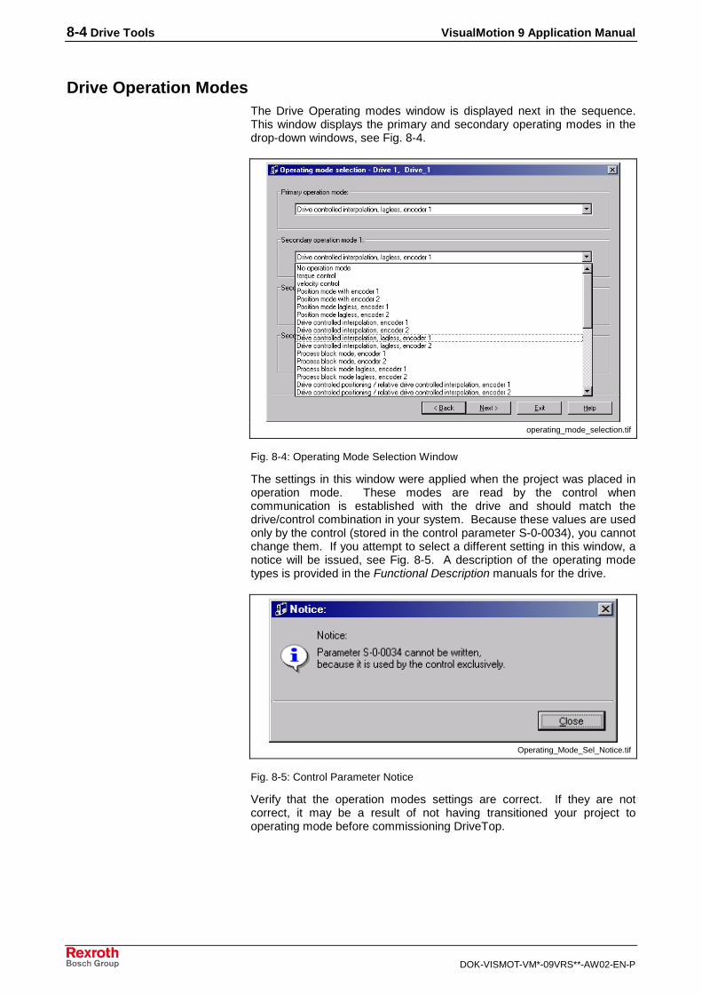
8-4 Drive Tools VisualMotion 9 Application Manual
DOK-VISMOT-VM*-09VRS**-AW02-EN-P
Drive Operation ModesThe Drive Operating modes window is displayed next in the sequence.This window displays the primary and secondary operating modes in thedrop-down windows, see Fig. 8-4.
operating_mode_selection.tif
Fig. 8-4: Operating Mode Selection Window
The settings in this window were applied when the project was placed inoperation mode. These modes are read by the control whencommunication is established with the drive and should match thedrive/control combination in your system. Because these values are usedonly by the control (stored in the control parameter S-0-0034), you cannotchange them. If you attempt to select a different setting in this window, anotice will be issued, see Fig. 8-5. A description of the operating modetypes is provided in the Functional Description manuals for the drive.
Operating_Mode_Sel_Notice.tif
Fig. 8-5: Control Parameter Notice
Verify that the operation modes settings are correct. If they are notcorrect, it may be a result of not having transitioned your project tooperating mode before commissioning DriveTop.

VisualMotion 9 Application Manual Drive Tools 8-5
DOK-VISMOT-VM*-09VRS**-AW02-EN-P
Drive ScalingInformation for the mechanical setup of the drive is entered in theScaling/units window. To open the window:
1. Select Commission ⇒ Drive Overview.
2. Click the Overview button to open the DriveTop – Drive statuswindow.
DriveTop_Scaling.tif
Fig. 8-6: Drive Functions Menu
3. Select Drive Functions ⇒ Scaling.
4. In the Scaling/units window, adjust the position units to reverse thedrive direction.

8-6 Drive Tools VisualMotion 9 Application Manual
DOK-VISMOT-VM*-09VRS**-AW02-EN-P
DriveTop_Scaling_Units.tif
Fig. 8-7: Drive Scaling/units
The default settings for the units of position, velocity, and acceleration canbe changed by selecting the Advanced… button. Changes in theseparameters are picked up by the drive and may affect the position,velocity, and acceleration profile of the axis.
Additional information about drive scaling can be found in the FunctionalDescription manual for the drive.
Homing the DriveThe drive homing setup establishes a relationship between the positionfeedback of an absolute encoder to the machine’s zero point. To setupdrive homing, select Homing/set absolute measurement ⇒ Motorencoder… from the Drive Functions menu in DriveTop.
The Homing/set absolute measurement window for the optional encoderhas similar fields to the Motor encoder for setting up homing.

VisualMotion 9 Application Manual Drive Tools 8-7
DOK-VISMOT-VM*-09VRS**-AW02-EN-P
Homing_Motor_Encoder.tif
Fig. 8-8: Homing/set Absolute Measurement: Motor Encoder
Absolute encoder monitoring window – Absolute encoder monitoringcompares the position saved during the last power down with the currentabsolute feedback value and displays the compared value in this field.This value is stored in drive parameter P-0-0097.
Ref. Distance – The value entered in this field is the distance betweenthe machine zero-point and position feedback value 1. This value isstored in drive parameter S-0-0052.
Position encoder value – This field shows the current value of theposition feedback. After the set absolute measurement procedure iscompleted, the value in this field (stored in drive parameter S-0-0051)should equal the value of the Ref. Distance.

8-8 Drive Tools VisualMotion 9 Application Manual
DOK-VISMOT-VM*-09VRS**-AW02-EN-P
Travel Limits for Software and Hardware (End Switches – checkingsafety features of drive setup)
The travel limits and end switches can be set in DriveTop through theDrive limitations, position limits window. Internal travel limits and externaltravel limit switches can be monitored by setting this capability in thewindow, see Fig. 8-9.
Travel_Limits.tif
Fig. 8-9: Drive limitations, position limits Window

VisualMotion 9 Application Manual Profibus Fieldbus Interface 9-1
DOK-VISMOT-VM*-09VRS**-AW02-EN-P
9 Profibus Fieldbus Interface
9.1 General Information
Version Note:Information in this document is based on VisualMotion Toolkitsoftware version 09VRS and PPC-R firmware versionGPP09VRS.
VisualMotion 9 software is downward compatible with GPP firmware, but,depending on the hardware platform selected, the type of fieldbuscommunication selection may be limited. The following table lists thefieldbus firmware versions and the available fieldbus interfaces for eachversion.
FieldbusInterfaces
PPC-RGPP07VRS
PPC-RGPP08VRS
PPC-RGPP09VRS
PPC-PGMP09VRS
Profibus • • • NoFieldbusSupport
Table 9-1: Fieldbus Firmware Version and Interface Type
Note: For fieldbus hardware information, refer to the VisualMotion 9Project Planning Manual.
PPC-R System Description with a FieldbusThe PPC-R can operate on a serial fieldbus interface (network) by meansof a fieldbus expansion card that communicates with the PPC-R via dual-port RAM. The function of the fieldbus card is similar to that of a networkcard in a PC; it allows communication with other devices on the network.
In Fig. 9-1, a typical fieldbus interface is illustrated with the following:
• Fieldbus Master - PLC fieldbus interface
• Fieldbus Slave - PPC-R fieldbus interface
In this document, we will refer to the PLC as the fieldbus master and thePPC-R as the fieldbus slave.

9-2 Profibus Fieldbus Interface VisualMotion 9 Application Manual
DOK-VISMOT-VM*-09VRS**-AW02-EN-P
����� ���
��
��
����
��
"�
��
��
����
�� ����#
$%��& & ���$%�
����'�'�'�(�(�
�'�"
����"
���
�� ��
�
��
��#(�
��#(�
280
9#�)�4'�+��!��
/:&
9#�)�4'��&;<)#<& 66'�#<�!# �
9#�)�4'���)�(�=/� *#4'�>
& 66'�#<�!# ��4�!%���//&?�����*#�)�4'�(#���'�)?" �!��+
= "��!����!�@��(��;���6�>
��&0�
PPCR_02_profibus_sercos.FH7
Fig. 9-1: Sample Master/Slave Setup with Fieldbus Card
With the PPC-R, the fieldbus card can be used only as a slave card in amaster/slave setup.
The VisualMotion Fieldbus MapperIn the VisualMotion software package, the Fieldbus Mapper is a tool usedto set up fieldbus configuration and data mapping. Fieldbus hardwareplatform selections are made through the Fieldbus Mapper window withVisualMotion Toolkit in Service Mode. To select the Fieldbus hardwareplatform:
1. Open VisualMotion in Service Mode, indicated by the service modesymbol ( ) in the lower right corner of the VisualMotionToolkit window.
2. Select Commission ⇒ Fieldbus Mapper to open the FBMapperwindow.
3. Click or select File ⇒ New to open the Fieldbus Slave Definitionwindow.
When a hardware platform is selected, only the fieldbus types availablefor that platform can be selected, see Table 9-1.
Data Transfer Direction (Output vs. Input)In the VisualMotion Fieldbus Mapper, output and input are alwaysdescribed with respect to the fieldbus master. The definitions for outputand input are:
output: the communication from the PLC to the PPC-R (i.e. from thefieldbus master to the fieldbus slave).Synonyms for this type of communication: send or write data.
input: the communication from the PPC-R to the PLC (i.e. from thefieldbus slave to the fieldbus master).Synonyms for this type of communication: receive or read data.
Fieldbus Data Channel DescriptionsThe Bosch Rexroth Profibus fieldbus interface card for the PPC-Rsupports the cyclic (DP) channel, which is made up of the following twoparts:
• Real-Time Channel (for single and multiplex channels)
• Parameter Channel (for systems requiring non-cyclic transmissions)

VisualMotion 9 Application Manual Profibus Fieldbus Interface 9-3
DOK-VISMOT-VM*-09VRS**-AW02-EN-P
Cyclic (DP) ChannelCyclic data is user-defined. It is stored in two ordered lists (C-0-2600 forinput data, C-0-2601 for output data) and transmitted serially over the bus.
The cyclic data channel is limited to 64 input words and 64 output words.PPC-R data types consume these words in either one-word (or 16-bit)groups for PPC-R registers or two-word (or 32-bit) groups for all otherdata types.
The PPC-R mapping list is scanned every 4 ms and data is sent andreceived to/from the fieldbus slave board's dual port RAM.
The cyclic data channel can be made up of any combination of thefollowing data types:
• Real-Time Channel
− Single Channel
− Multiplex Channel
• Parameter Channel
word 31 word 0
Multiplex Channel Single Channel Parameter Channel
Real-Time Channel
Cyclic (DP) Channel
Multiplex Channel Parameter Channel
word 31
Real-Time Channel
Cyclic (DP) Channel
word 0
Single Channel Only
word 31 word 0
Real-Time Channel
Cyclic (DP) Channel
word 13 or 5
Parameter Channel Only
word 0
(NO Real-Time Channel)
Cyclic (DP) Channel
BasicConfigurations
word 31 word 0
Single Channel Parameter Channel
Real-Time Channel
Cyclic (DP) Channel
word 0word 31
Real-Time Channel
MultiplexChannel
Cyclic (DP) Channel
Single Channel
Multiplex Channel Only
word 31 word 0
Real-Time Channel
Cyclic (DP) Channel
Fig. 9-2: Configuration Options for the Cyclic Data Channel

9-4 Profibus Fieldbus Interface VisualMotion 9 Application Manual
DOK-VISMOT-VM*-09VRS**-AW02-EN-P
The Real-Time ChannelIn the real-time channel, data is updated cyclically between the fieldbusmaster and slave. This channel contains two possible data types: singleand multiplex.
Cyclic Data: Types and SizesThe following table outlines the PPC-R data types that can be transmittedvia the cyclic channel and the amount of space (in 16-bit data words) thateach data type consumes.
Note: The cyclic data mapping lists support only 16- and 32-bit data ofthe following types for reading and writing:- Integer- Float- Binary (used in control parameters)- Hex (used in control parameters)For all other data types (e.g. diagnostic messages - “strings”), usethe Parameter Channel.
PPC-R Data Type Data Size(in 16-Bit Words)
Register 1
Program Integer (currently active program ONLY *) 2
Program Float (currently active program ONLY *) 2
Global Integer 2
Global Float 2
Card Parameter 2
Axis Parameter 2
Task Parameter 2
Note: Drive parameters "S" or "P" cannot be transmitted cyclicallybecause of the inherent delay of parameter access over the SERCOSservice channel. See "Parameter Channel." However, if a drive parameteris mapped to an Axis Parameter, that Axis parameter could be used incyclic data (see description of Axis Parameters 180-196 in theVisualMotion Functional Description).
* Important Note: Integers and floats are shown only for the currentlyactive program. Each time you activate a new progam, the fieldbusreads/writes to the newly-activated program.
Table 9-2: PPC-R Cyclic Data Types and Sizes
Single Data TypesSingle data types are mapped directly in the cyclic mapping ordered lists(C-0-2600, C-0-2601). The data types are updated every 4 ms via dual-port RAM.
Multiplex Data Types(Cyclic Data Channel)In some multi-axis applications, 64 words of cyclic data transfer are notsufficient to meet the requirement of the application.
When insufficient data transfer space is available, multiplex data can beset up within the cyclic channel. One multiplex container acts as aplaceholder for multiple possible PPC-R data types (all of the same wordsize). The currently transmitted PPC-R data type is based on an indexvalue placed in a multiplex control or status word attached to the end ofthe cyclic list. Depending on the index specified by the master, themultiplex channel permits a different set of data within the cyclic channelto be transferred as current real-time data. Multiplex containers can be
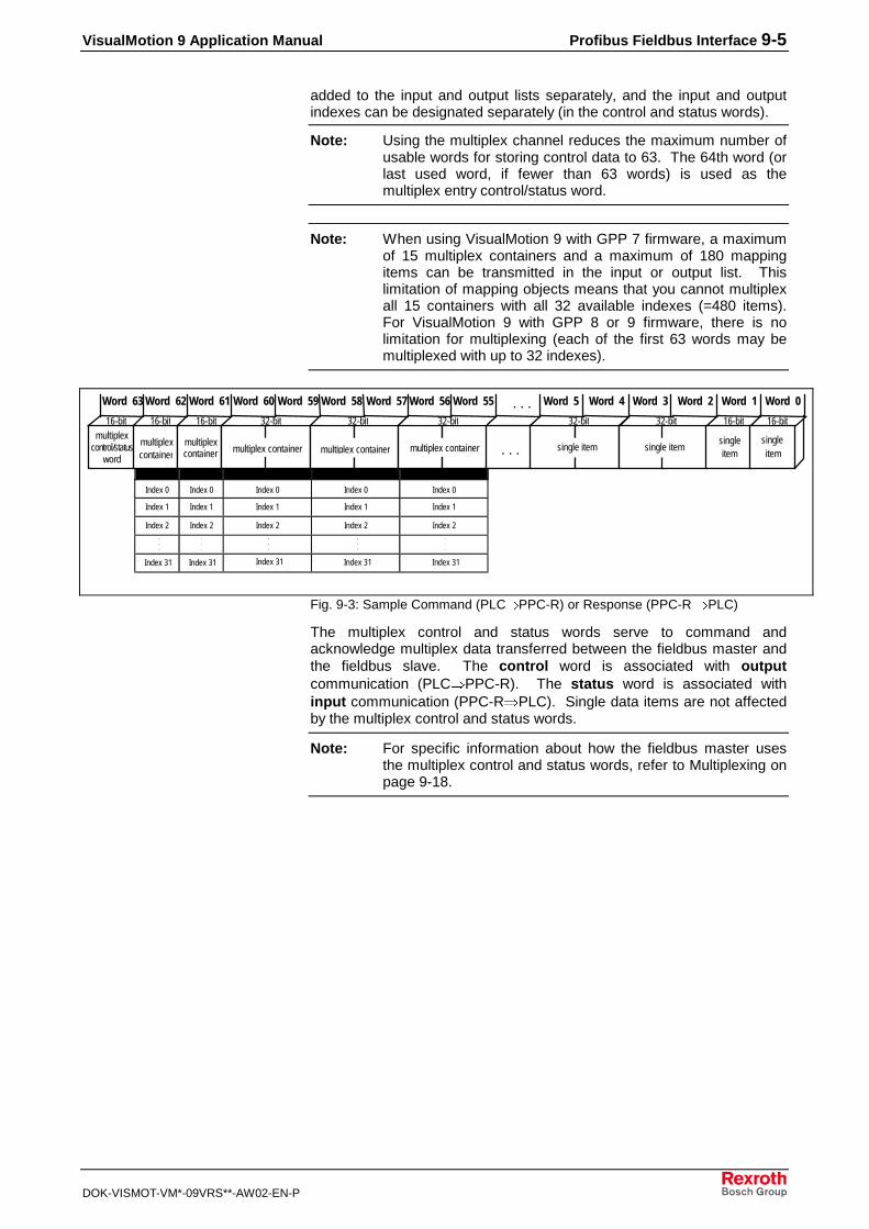
VisualMotion 9 Application Manual Profibus Fieldbus Interface 9-5
DOK-VISMOT-VM*-09VRS**-AW02-EN-P
added to the input and output lists separately, and the input and outputindexes can be designated separately (in the control and status words).
Note: Using the multiplex channel reduces the maximum number ofusable words for storing control data to 63. The 64th word (orlast used word, if fewer than 63 words) is used as themultiplex entry control/status word.
Note: When using VisualMotion 9 with GPP 7 firmware, a maximumof 15 multiplex containers and a maximum of 180 mappingitems can be transmitted in the input or output list. Thislimitation of mapping objects means that you cannot multiplexall 15 containers with all 32 available indexes (=480 items).For VisualMotion 9 with GPP 8 or 9 firmware, there is nolimitation for multiplexing (each of the first 63 words may bemultiplexed with up to 32 indexes).
Index 0 Index 0 Index 0 Index 0 Index 0
Index 1 Index 1 Index 1 Index 1 Index 1
Index 2 Index 2 Index 2 Index 2 Index 2...
Index 31 Index 31 Index 31 Index 31 Index 31
multiplex containermultiplex
control/statusword
multiplex containercontainer
16-bit 16-bit 16-bit 32-bit 32-bit
multiplex container
32-bit
multiplexcontainer . . . single item
32-bit
Word 63 Word 0
single item
32-bit 16-bit
singleitem
16-bit
singleitem
Word 1Word 2Word 3Word 4Word 5. . .Word 55Word 56Word 57Word 58Word 59Word 60Word 61Word 62
.
.
.
.
.
.
.
.
.
.
.
.
multiplex
Fig. 9-3: Sample Command (PLC⇒PPC-R) or Response (PPC-R ⇒PLC)
The multiplex control and status words serve to command andacknowledge multiplex data transferred between the fieldbus master andthe fieldbus slave. The control word is associated with outputcommunication (PLC⇒PPC-R). The status word is associated withinput communication (PPC-R⇒PLC). Single data items are not affectedby the multiplex control and status words.
Note: For specific information about how the fieldbus master usesthe multiplex control and status words, refer to Multiplexing onpage 9-18.

9-6 Profibus Fieldbus Interface VisualMotion 9 Application Manual
DOK-VISMOT-VM*-09VRS**-AW02-EN-P
/:&
�+�6
�;
/:&
�+�6
�;
/:&
�+�6
�;
&;<)#<�&��
���)
&;<)#<�&��
���)
&;<)#<�&�����)
2���A��� 2���A��� 2���A���
���% ����� �?6
')!#")�A�����!�
���% ����� �?6
')!#")�A�����!�
���% ����� �?6
')!#")�A�����!�
+')!#")�A#�$< �!� )�8��!�!'�% ��
+')!#")�A& �!�#�����+')!#")�A& �!�#�����+')!#")�A& �!�#�����
+')!#")�A& �!�#�����+')!#")�A& �!�#�����+')!#")�A& �!�#�����
+')!#")�A& �!�#�����+')!#")�A& �!�#�����+')!#")�A& �!�#�����
�������� ��������! ��������"
multiplexing.FH7
Fig. 9-4: Examples for Reading Data via the Multiplex Channel
Parameter ChannelFor Profibus systems using the PPC-R/VisualMotion configuration, a subsetof the cyclic (DP) channel can be allocated for non-cyclic communications(e.g. parameterization and extended diagnostic information). This subset ofthe cyclic channel is called the Parameter Channel.
Note: The Parameter Channel is always allocated as the first 2, 4 or6 words of the Profibus cyclic (DP) channel. The length of theParameter Channel plus the length of the Real-time Channelused to exchange cyclic data represents the entire length ofthe DP channel (maximum total length: 64 words). Refer toFig. 9-2 for DP channel configuration options.
Two messaging formats are available in the Parameter Channel, to allowfor a varying degree of implementation, depending on applicationrequirements:
• Short Format 3- messaging format that provides direct access toRexroth mapped objects (Registers, Global Floats, Global Integers,Floats, Integers, as well as Card, Axis, Task, and Drive S and Pparameters).
Note: List parameters can be accessed using the Data ExchangeObject. For further explanation of how this format functions,refer to Messaging Formats on page 9-24.
• VisualMotion ASCII Format- provided for backward-compatibilitywith previous VisualMotion versions. For specific information aboutthis format, refer to the VisualMotion 9 Functional Description manual.

VisualMotion 9 Application Manual Profibus Fieldbus Interface 9-7
DOK-VISMOT-VM*-09VRS**-AW02-EN-P
9.2 Fieldbus Mapper Functionality
Initializing the Fieldbus Mapper from VisualMotion 9When configuring a new Fieldbus Mapper, the procedure will varydepending on the mode of VisualMotion.
To configure a Fieldbus Mapper in Project mode:
1. Open an existing program or create a new program. You must beusing PPC-R hardware with GPP firmware to use the FieldbusMapper described in this document.
2. Select Commission ⇒ Fieldbus Mapper. The main FieldbusMapper window opens empty (refer to Fig. 9-5).
FB_Mapper_New.tif
Fig. 9-5: FBMapper – Project Window
3. Click or select File ⇒ New.
A “setup wizard” goes through three steps:
• Fieldbus Slave Definition
• Fieldbus Slave Configuration
• Cyclic Data Configuration
4. Enter the information requested in the setup windows. For moredetails on each step, refer to Fieldbus Slave Definition, FieldbusSlave Configuration, and Cyclic Data Configuration for detailedinformation about each configuration step.
5. Save the file (automatically has a *.prm extension) to the projectfolder on the computer if you are in offline mode If you are in onlinemode, download the configured Fielbus Mapper to the control.
If you are offline, the configured Fielbus Mapper is saved to the projectfile. If you are online, download the configured Fieldbus Mapper to thecontrol and synchronize project.
When editing an existing Fieldbus Mapper, refer to the Programmingchapter for information on how commissioning tools are handled inProject Mode, online and offline, and in Service mode.
If you are configuring a new Fieldbus Mapper while VisualMotion is inService mode, the Fieldbus Mapper window will open empty whencommissioned. After configuring the new Fieldbus Mapper, download thedata to the control. Selecting File ⇒ Save will save the configuredFieldbus Mapper to a separate file from the project file. To bring theFieldbus Mapper file into the project, use the import procedure:
1. Select File ⇒ Import.
2. Browse to find the desired file (*.prm extension).
Project Mode
Service Mode

9-8 Profibus Fieldbus Interface VisualMotion 9 Application Manual
DOK-VISMOT-VM*-09VRS**-AW02-EN-P
3. Click Open. The main Fieldbus Mapper window appears, which liststhe configuration information. Refer to Fig. 9-6 below.
FB_Mapper_Main.tif
Fig. 9-6: FBMapper-Project Window
Editing a Fieldbus MapperTo Add/Insert, Edit, or Delete an item in a Fieldbus Mapper file, open theSelected Mapping List menu from the Edit menu (refer to Fig. 9-7below). For more information about each step, refer to Fieldbus SlaveDefinition, Fieldbus Slave Configuration, and Cyclic Data Configuration fordetailed information about each configuration step.
FB_Mapper_Edit_Menu.tif
Fig. 9-7: Fieldbus Mapper Edit Menu
Note: You can also directly add, insert, delete, edit an item, or createa new list by:• clicking on the item to be edited in the main Fieldbus
Mapper window and selecting the desired function underEdit ⇒ Selected Mapping List
OR• right-clicking on an item to display a menu of functions
Fieldbus Slave DefinitionTo configure a Fieldbus Slave, select the fieldbus type and hardwareplatform in the Fieldbus Slave Definition window, see Fig. 9-8. Refer toTable 9-1 for a list of the hardware platforms available for Profibus. The

VisualMotion 9 Application Manual Profibus Fieldbus Interface 9-9
DOK-VISMOT-VM*-09VRS**-AW02-EN-P
hardware platform can only be selected when VisualMotion is inUnsynchronized mode.
FB_Mapper_Profibus.tif
Fig. 9-8: Fieldbus Slave Definition Window
Fieldbus Slave ConfigurationThe Profibus Fieldbus Slave Configuration window is shown in Fig. 9-9below.
FB_Slave_Config_PB.tif
Fig. 9-9: Fieldbus Slave Configuration
• Device Address (0-125): set to a unique number for the devices onthe bus
• Parameter Channel Length (words): set to 0 (Off), 2, 4 or 6 words.If 2, 4 or 6 words are selected, these are automatically allocated forthe Parameter Channel in the Cyclic Data Input and Output Lists.
Set the Error Reaction to Shutdown (default), Warning or Ignore. Refer toFieldbus/PLC Cyclic Read/Write Monitoring
Monitoring of Fieldbus read/write capabilities to the cyclic channel areassociated with three parameters:
• C-0-2611 Fieldbus/PLC Cyclic Channel: Current Number of Misses–displays the current number of transfers to/from the cyclic channel.
• C-0-2612 Fieldbus/PLC Cyclic Channel: Peak Number of Misses –displays the maximum number of missed transfers to/from the cyclicchannel.
Standard Fieldbus ConfigurationOptions:
Fieldbus Error Reaction:

9-10 Profibus Fieldbus Interface VisualMotion 9 Application Manual
DOK-VISMOT-VM*-09VRS**-AW02-EN-P
• C-0-2613 Fieldbus/PLC Cyclic Channel: Timeout Counter – displaysthe number of timeouts in the cyclic channel. If after 4 ms, the CyclicMapping Lists are not successfully transmitted, a "miss" is noted.
For more information about these parameters, see the VisualMotion 9Functional Description manual.
Fieldbus Error Reaction on page 9-16 for detailed information about eachsetting.
The Advanced Options field is shown only if the checkbox next to ShowAdvanced Configuration Options is checked (refer to Fig. 9-10 below).In most cases, the default options should apply.
FB_Slave_Config_PB_Adv.tif
Fig. 9-10: Fieldbus Slave Configuration: Advanced
• Multiplex Method: select Primary or Secondary (Primary is thedefault). Select Secondary only if you have an inconsistent fieldbusmaster. Refer to Multiplexing on page 9-18 for detailed informationabout each method.
Cyclic Data ConfigurationAn example of the Cyclic Data Configuration window is shown in Fig. 9-11below. In this window, four words have been allocated for the ParameterChannel (optional for Profibus fieldbuses only). If you are editing anexisting Fieldbus Mapper file, the list will probably contain more items.
First, you must select the Cyclic Input List (from PPC-R to PLC) or theCyclic Output List (from PLC to PPC-R).
Cyclic_Data_Config.tif
Fig. 9-11: Cyclic Data Configuration
Advanced Configuration Options

VisualMotion 9 Application Manual Profibus Fieldbus Interface 9-11
DOK-VISMOT-VM*-09VRS**-AW02-EN-P
Adding an Item to the List1. Select the Cyclic Input List or the Cyclic Output List.
2. Click Add. The window in Fig. 9-12 is displayed. Select the DataType (for example, Register).
Cyclic_Data_Add.tif
Fig. 9-12: Add Item to Cyclic Data
3. Enter the required information (for example Register Number) orselect it from the drop-down list. Only the available data types foryour designated VisualMotion hardware setup and fieldbus type arelisted.
4. Click OK to add the selected item to the list.
Adding Multiplex Containers to the List1. Select the Cyclic Input List or the Cyclic Output List.
2. Click Add.
3. In the Add Item window under Select the Data Type, selectMultiplex Container 16-bit (for Registers) or Multiplex Container32-bit (for all other data types).
Note: At this point, the Multiplex Containers do not yet contain anyitems. To add multiplex items, refer to below.
Adding Items to an Empty Multiplex Container1. In the Cyclic Data Configuration window, select the multiplex
container to which you want to add items.
2. Click Add. The window in Fig. 9-13 below appears. Because it isunclear whether you would like to add to the list or to the multiplexcontainer, the Fieldbus Mapper is requesting clarification.

9-12 Profibus Fieldbus Interface VisualMotion 9 Application Manual
DOK-VISMOT-VM*-09VRS**-AW02-EN-P
Add_Multiplex.tif
Fig. 9-13: Add Item or Multiplex Item Window
Note: For subsequent items, highlight any of the indexes within themultiplex container before clicking Add, and the Fieldbus Mapper willknow you want to add to that container.
3. To add to the selected multiplex container, click No. The window inFig. 9-14 below is an example for adding a 32-bit multiplex item.
4. Select the desired item to be added to the multiplex container in theAdd 32-bit Multiplex Item window.
Add_Multiplex_Item.tif
Fig. 9-14: Select Data Type for Multiplex Item
Note: In addition to the data types that can be added to the multiplexlist, an empty item called Multiplex Empty Item is available tofill a space within the multiplex container, if nothing is to bemapped to a particular index.

VisualMotion 9 Application Manual Profibus Fieldbus Interface 9-13
DOK-VISMOT-VM*-09VRS**-AW02-EN-P
5. Click OK. The item is automatically placed in the multiplex containeras the next unassigned index item (e.g. the first item is index 00, thelast is index 31).
6. Repeat for as many items as you want to add to the multiplexcontainer, up to 32 items.
Editing the Cyclic Data ListsTo make changes to an existing list, use the following buttons:
Button Function
Inserts a new item at the end of the list.
Inserts a new item into the list directly before the selected item.
Removes the selected item from the list.
Allows editing of the selected item. (To edit a list item, youmay also double-click on it.)
Clears up the current list.
Table 9-3: Button Functions in the Cyclic Data Configuration Window
Additional FunctionsSeveral additional functions are available in the Fieldbus Mapper:
Menu Item Function
Print Print the current fieldbus configuration data.
Print Preview Preview the printout of the current fieldbus configuration data
Print Setup Configure printer settings
Table 9-4: Additional Functions

9-14 Profibus Fieldbus Interface VisualMotion 9 Application Manual
DOK-VISMOT-VM*-09VRS**-AW02-EN-P
Getting the Fieldbus Configuration from the PPCAfter getting the fieldbus configuration from the PPC while in Service Modeor Project mode (online), the following information is detected by the systemand appears in the configuration list:
• Fieldbus Type Found
• Fieldbus FW (Firmware) Version
• GPP Control FW (Firmware) Version
An example is shown in Fig. 9-15 below.
FB_Mapper_Online.tif
Fig. 9-15: On-Line Fieldbus Configuration Information

VisualMotion 9 Application Manual Profibus Fieldbus Interface 9-15
DOK-VISMOT-VM*-09VRS**-AW02-EN-P
9.3 Information for the GPP Programmer
Fieldbus StatusVisualMotion Register 19 holds the information for "Fieldbus Status." Theregister information can be referenced in a VisualMotion applicationprogram to respond to the status of each bit. The use of these bits isapplication-dependent.
Table 9-5 below contains the bit assignment for the diagnostic object 5ff2.The assigned bits are labeled with "x" and the bit number in the secondrow. Unassigned bits are labeled with "---."
16 15 14 13 12 11 10 9 8 7 6 5 4 3 2 1
--- x15 --- --- --- --- --- --- --- --- --- x5 x4 --- x2 x1
Table 9-5: Bit Assignment for VisualMotion Register 19
Bit DefinitionsStatus bits for the internal DPR (Dual-Port RAM) communication betweenthe fieldbus slave and the PPC-R:
x1: FB Init. OK , LSB (least significant bit)
x2: FB Init. OK, MSB (most significant bit)
The bit combinations for x1 and x2 are as follows:
Bit 2(PPC-R)
Bit 1(Fieldbus)
Description
0 0 A reset has been executed on the DPR,orneither the PPC-R nor the fieldbus cardhave initialized the DPR.
0 1 The DPR is initialized by the fieldbus card,but not yet by the PPC-R.
1 0 The DPR initialization is complete. DPRhas been initialized by the fieldbus cardand PPC-R. Fieldbus to PPC-Rcommunications system is ready.
1 1 Fieldbus to PPC-R communications systemis ready.
Table 9-6: Possible Settings for Bits 1 and 2, Status Bits for DPR Communication
Status bit for the active bus capabilities of the fieldbus slaves (FB SlaveReady)
This bit is monitored for the Fieldbus Error Reaction. Whenever this bitgoes to 0 after a fieldbus card was initially found by the PPC-R, theselected Error Reaction (system shutdown, error message, or ignore) isinitiated. Refer to Fieldbus/PLC Cyclic Read/Write Monitoring
Monitoring of Fieldbus read/write capabilities to the cyclic channel areassociated with three parameters:
• C-0-2611 Fieldbus/PLC Cyclic Channel: Current Number of Misses–displays the current number of transfers to/from the cyclic channel.
• C-0-2612 Fieldbus/PLC Cyclic Channel: Peak Number of Misses –displays the maximum number of missed transfers to/from the cyclicchannel.
• C-0-2613 Fieldbus/PLC Cyclic Channel: Timeout Counter – displaysthe number of timeouts in the cyclic channel. If after 4 ms, the CyclicMapping Lists are not successfully transmitted, a "miss" is noted.
For more information about these parameters, see the VisualMotion 9Functional Description manual.
x1, x2
x4

9-16 Profibus Fieldbus Interface VisualMotion 9 Application Manual
DOK-VISMOT-VM*-09VRS**-AW02-EN-P
Fieldbus Error Reaction on page 9-16 for an explanation of the FieldbusError Reaction setting.
0--> The fieldbus slave is not (yet) ready for data exchange.
1--> The fieldbus slave can actively participate on the bus.
Status bit for the non-cyclic channel (Parameter Channel) (Non-CycReady)
0--> The non-cyclic channel (Parameter Channel) cannot (yet) be used.
1--> The non-cyclic channel (Parameter Channel) is ready for use by thefieldbus master.
Status bit for the cyclic data output (Cyclic Data Valid):
0--> The cyclic data outputs (coming in to the PPC-R) are INVALID.
1--> The cyclic data outputs (coming in to the PPC-R) are VALID. Thesystem looks for this bit to be 1 before allowing data transfer.
Fieldbus DiagnosticsVisualMotion Register 20 holds the information for "Fieldbus Diagnostics."
Table 9-7 below contains the bit assignment for fieldbus diagnostics. Theassigned bits are labeled with "x" and the bit number in the second row.Unassigned bits are labeled with "---."
16 15 14 13 12 11 10 9 8 7 6 5 4 3 2 1
X16 x15 x14 x13 --- --- --- --- --- --- --- --- --- --- --- ---
Table 9-7: Bit Assignment for VisualMotion Register 20
Bit DefinitionsIdentification of the fieldbus interface card (FB Card Found)
The bit combinations for x13, x14 and x15 are as follows:
Bit 16 Bit 15 Bit 14 Bit 13 Fieldbus Type
0 0 0 0 <NO CARD>
0 0 0 1 <Not Defined>
0 0 1 0 Interbus
0 0 1 1 DeviceNet
0 1 0 0 Profibus
0 1 0 1 ControlNet
0 1 1 0 <Not Defined>
0 1 1 1 EtherNet/IP (10 MB)
1 1 1 1 Indramat PLC Interface
Table 9-8: Identification of the Fieldbus Interface
Fieldbus/PLC Cyclic Read/Write MonitoringMonitoring of Fieldbus read/write capabilities to the cyclic channel areassociated with three parameters:
• C-0-2611 Fieldbus/PLC Cyclic Channel: Current Number of Misses–displays the current number of transfers to/from the cyclic channel.
• C-0-2612 Fieldbus/PLC Cyclic Channel: Peak Number of Misses –displays the maximum number of missed transfers to/from the cyclicchannel.
x5
x15
x13 - x16

VisualMotion 9 Application Manual Profibus Fieldbus Interface 9-17
DOK-VISMOT-VM*-09VRS**-AW02-EN-P
• C-0-2613 Fieldbus/PLC Cyclic Channel: Timeout Counter – displaysthe number of timeouts in the cyclic channel. If after 4 ms, the CyclicMapping Lists are not successfully transmitted, a "miss" is noted.
For more information about these parameters, see the VisualMotion 9Functional Description manual.
Fieldbus Error Reaction
Note: The Fieldbus Error Reaction setting is active only in SERCOSPhase 4. In all other SERCOS phases, it will be inactive.
You can select how you would like the PPC-R system to react in case of afieldbus error. This reaction can be set in the "Fieldbus SlaveConfiguration" window, using the combo box labeled "Fieldbus ErrorReaction."
Three options are available for the Error Reaction setting. Depending onthe selected setting, the value 0, 1, or 2 is stored in Parameter C-0-2635:
Setting Value in Parameter C-0-2635
Shutdown 0 (default)
Warning Only 1
Ignore 2
Table 9-9: Parameter C-0-2635 Values for Error Reaction Settings
Fieldbus Mapper TimeoutThe Fieldbus Mapper continually scans the system for sufficientresources to process the cyclic data mapping lists (2600 and 2601 lists).If 10 out of 10 consecutive attempts of the mapping list updates areincomplete, the system is considered to have insufficient resources andthe selected error reaction is evoked, as follows:
If "Shutdown" (0) is set in Parameter C-0-2635, the following error isgenerated from the PPC-R card: 520 Fieldbus Mapper Timeout
If "Warning Only" (1) is set in Parameter C-0-2635, the following error isgenerated: 209 Fieldbus Mapper Timeout
If "Ignore" (2) is set in Parameter C-0-2635, the system will update asresources become available, but there is no way to monitor whether or notupdates actually occur.
Lost Fieldbus ConnectionRegister 19, bit 4 indicates the status of the fieldbus. Refer to FieldbusStatus on page 9-15 for more specific bit information. The systemmonitors this bit and evokes the selected error reaction if the bit is low (0),after a fieldbus card is found. A typical situation that will cause thiscondition is the disconnection of the fieldbus cable from the fieldbus card.
If "Shutdown Control" (0) is set in Parameter C-0-2635, the following erroris generated from the PPC-R (active in SERCOS Phase 4 only):519 Lost Fieldbus Connection
If "Warning Only" (1) is set in Parameter C-0-2635, the following error isgenerated (active in SERCOS Phase 4 only):208 Lost Fieldbus Connection

9-18 Profibus Fieldbus Interface VisualMotion 9 Application Manual
DOK-VISMOT-VM*-09VRS**-AW02-EN-P
If "Ignore" (2) is set in Parameter C-0-2635, there is no noticeablereaction when Register 19 status bits go low, unless the GPP applicationprogram is customized to evoke a special reaction.
Troubleshooting Tip:
If a fieldbus card is not found on the system, the ErrorReaction setting will be ignored. If you have a fieldbus cardand the Error Reaction is not responding as expected, thesystem may not "see" your fieldbus card.
9.4 Information for the PLC Programmer
*.gsd FileBosch Rexroth supplies a *.gsd file on the VisualMotion 9 CD containingsupporting information for the PPC-R with a Profibus slave configuration.Contact a Rexroth technical representative for the location of this file.
Multiplexing
Primary Multiplex Method (for Consistent Masters only)
Important: You should not use the Primary Multiplex Method for amaster that is not consistent over the entire cyclic channel.The Secondary Multiplex Method is available for inconsistentmasters. Refer to Secondary Multiplex Method (forInconsistent Masters) on page 9-21.
The advantage of the Primary Method is easier handling of input data forconsistent masters.
Control Word and Status WordThe control word is transferred in the multiplex channel from master toslave. It tells the slave in which index the data is being transferred frommaster to slave and in which index the data is requested from slave tomaster.
15 14 13 12 11 10 9 8 7 6 5 4 3 2 1 0
Multiplex Output Control Index(index_out_c)
(defines the output index command formultiplexing)
Write RequestToggle Bit (WR)
(initiates the writecommand once each
time it is toggled)
Multiplex Input Control Index(index_in_c)
(defines the input index command formultiplexing)
Multiplex Input Control Byte Multiplex Output Control Byte
Fig. 9-16: Control Word Definition, Primary Multiplex Method
Index_out_c: tells the slave in which index the data are transferred frommaster to slave (out = master -> slave, _c = element of control word).
Index_in_c: tells the slave in which index the data is requested fromslave to master (in = slave -> master, _c = element of control word).
Control Word

VisualMotion 9 Application Manual Profibus Fieldbus Interface 9-19
DOK-VISMOT-VM*-09VRS**-AW02-EN-P
WR (Write Request): handshake bit (refer to meaning of WR and WA).
Note: Input data via the Multiplex Channel is continually beingupdated.
15 14 13 12 11 10 9 8 7 6 5 4 3 2 1 0
Multiplex Input Status Index(index_in_s)
(confirms that the input index responselocation matches that of the command
location)
Multiplex Output Status Index(index_out_s)
(confirms that the output index responselocation matches that of the command
location)
Write RequestAcknowledge Bit
(WA)(checks that the writedata has been readonce each time it is
toggled)
Multiplex Input Status Byte Multiplex Output Status Byte
Fig. 9-17: Status Word Definition, Primary Multiplex Method
• Index_out_s: acknowledges index written by the master (out = master-> slave, _s = element of status word).
• Index_in_s: tells the master which index is transferred from slave tomaster in the actual process data cycle (in = slave -> master, _s =element of status word).
• WA (Write Acknowledge): Handshake bit (refer to meaning of WRand WA).
Handshake Bits WR and WAWR and WA are handshake bits that allow the controlled writing of datavia the multiplex channel. WR and WA control the data transfer forwriting data_out (data send from master to slave).WR == WA:
• tells the master that the slave has received the last multiplex data_out.The master can now send new data_out.
• tells the slave to do nothing, because the master has not yet put newconsistent data_out on the bus.
WR! = WA:
• tells the slave to do something, because the master has now putconsistent new data_out on bus.
• tells the master to do nothing, because the slave has not yet receivedthe latest multiplex data_out.
Status Word

9-20 Profibus Fieldbus Interface VisualMotion 9 Application Manual
DOK-VISMOT-VM*-09VRS**-AW02-EN-P
Master Communications (Primary Multiplex Method)
Begin
Control word =0
Index_in_c ==Index_in_s ?
Read Index_in_s,Read Data_in,
Write Index_in_c
WR == WA ? Write Data_out,Write Index_out_c,
Toggle RT (Set WR = ~WA)
Read Data_in
Write Data_out
Yes
No
Yes
No
Fig. 9-18: Primary Multiplex Method, Master Communications
Programming ExampleTo aid in implementing the multiplex function in a PLC program, thefollowing flow chart shows two ways of reading and writing data. Readingand writing can be executed separately, which allows the input data to beupdated about 30% faster. The “Read Data” example would be placed atthe beginning of a PLC program the “Write Data” example at the end.
Combined reading and writing makes the PLC program simpler,especially when using the same index for both transfer actions.

VisualMotion 9 Application Manual Profibus Fieldbus Interface 9-21
DOK-VISMOT-VM*-09VRS**-AW02-EN-P
���������
���
�0
��#!��2�"'!�2���A
��#!��0'!"'!���!�! �+')!#")�A�& �!�#���=�>
��#!��0'!"'!�2���A
� $$)����#!���B'��!�.#!
�0
���
��������
#��
��������������
���������! ��2�"'!���!��*� 6
+C")�A�& �!�#���=�>
��!�/
:&�&;<)�
����/:&
�&;<)�
��#!��0'!"'!���!�! �+')!#")�A�& �!�#���=�>
+C")�A2�"'!
& �!� )�.;!�1
+C")�A�2�"'!�!�!'�.;!�D
+C")�A& �!� )� ��
+C")�A�!�!'�� ��D
���������! ��2�"'!���!��*� 6
+C")�A�& �!�#���=�>
+C")�A0'!"'!
& �!� )�.;!�1
+C")�A�0'!"'!�!�!'�.;!�D
��#!��2�"'!����0'!"'!�2���A��
� $$)����#!���B'��!�.#!
�0
1
multiplexing flow chart.FH7
Fig. 9-19: Flow Chart of Multiplex Programming Examples (Primary Method)
Secondary Multiplex Method (for Inconsistent Masters)
Explanation of the Master Consistency ProblemThe PPC-R fieldbus slave interfaces can guarantee consistency,however, some fieldbus masters can only guarantee byte, word, or doubleword consistency. Therefore, it is necessary to have a second multiplexmethod where both input data and output data require the handshake bitsto update via the fieldbus.
Note: The meanings of the control and status words are the same asfor the Primary Multiplex Method. The only difference is thetoggle bits RR and RA, which are used in the SecondaryMethod.
Fig. 9-20 below illustrates the control word definition for the SecondaryMultiplex Method.

9-22 Profibus Fieldbus Interface VisualMotion 9 Application Manual
DOK-VISMOT-VM*-09VRS**-AW02-EN-P
Multiplex Input Control Index(index_in_c)
(defines the input index command formultiplexing)
15 14 13 12 11 10 9 8 7 6 5 4 3 2 1 0
Multiplex Output Control Index(index_out_c)
(defines the output index command formultiplexing)
Write RequestToggle Bit (WR)
(initiates the writecommand once each
time it is toggled)
RRsee definition
under “HandshakeBits WR / WA and
RR / RA”(Secondary
Method only)
Multiplex Input Control Byte Multiplex Output Control Byte
Fig. 9-20: Control Word Definition, Secondary Multiplex Method
15 14 13 12 11 10 9 8 7 6 5 4 3 2 1 0
Multiplex Input Status Index(index_in_s)
(confirms that the input index responselocation matches that of the command
location)
RAsee definition
under “HandshakeBits WR / WA and
RR / RA”(Secondary
Method only)
Multiplex Output Status Index(index_out_s)
(confirms that the output index responselocation matches that of the command
location)
Write RequestAcknowledge Bit
(WA)(checks that the writedata has been readonce each time it is
toggled)
Multiplex Input Status Byte Multiplex Output Status Byte
Fig. 9-21: Status Word Definition, Secondary Multiplex Method
The Secondary Multiplex Method has the following features:
• You can transfer a different index from master to slave as from slaveto master.
• The handshake bits for both reading and writing of this multiplexchannel make the multiplexing possible on inconsistent systems(masters).
Handshake Bits RR and RARR (Read Request) and RA (Read Acknowledge) are handshake bits thatallow a controlled data transfer and use of the multiplex channel oninconsistent masters. RR and RA control the data transfer for readingdata_in (data send from slave to master).
RR == RA:
• tells the master that the slave has sent the requested data_in. Themaster can now read the data_in and request new data_in.
• tells the slave to do nothing, because the master has not yet put newconsistent data on the bus.
RR != RA:
• tells the slave to put new data_in on the bus, because the masterrequests new data_in.
• tells the master to do nothing, because the slave has not yet put thelatest requested multiplex data_in on the bus.
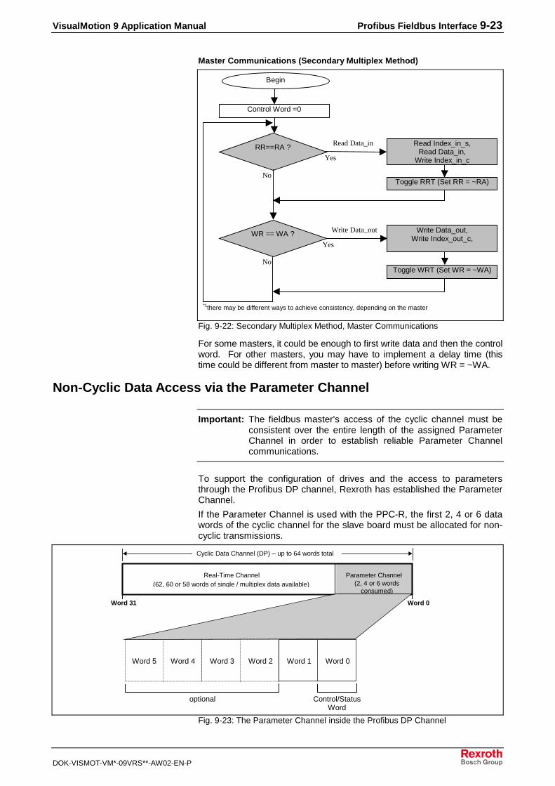
VisualMotion 9 Application Manual Profibus Fieldbus Interface 9-23
DOK-VISMOT-VM*-09VRS**-AW02-EN-P
Master Communications (Secondary Multiplex Method)
Begin
Control Word =0
RR==RA ? Read Index_in_s,Read Data_in,
Write Index_in_cYes
No
WR == WA ?
Yes
No
Write Data_out,Write Index_out_c,
Toggle WRT (Set WR = ~WA)
Read Data_in
Write Data_out
Toggle RRT (Set RR = ~RA)
*1there may be different ways to achieve consistency, depending on the master
Fig. 9-22: Secondary Multiplex Method, Master Communications
For some masters, it could be enough to first write data and then the controlword. For other masters, you may have to implement a delay time (thistime could be different from master to master) before writing WR = ~WA.
Non-Cyclic Data Access via the Parameter Channel
Important: The fieldbus master's access of the cyclic channel must beconsistent over the entire length of the assigned ParameterChannel in order to establish reliable Parameter Channelcommunications.
To support the configuration of drives and the access to parametersthrough the Profibus DP channel, Rexroth has established the ParameterChannel.
If the Parameter Channel is used with the PPC-R, the first 2, 4 or 6 datawords of the cyclic channel for the slave board must be allocated for non-cyclic transmissions.
Parameter Channel(2, 4 or 6 words
consumed)
Real-Time Channel(62, 60 or 58 words of single / multiplex data available)
Word 0Word 31
Cyclic Data Channel (DP) – up to 64 words total
Word 5 Word 4 Word 3 Word 2 Word 1 Word 0
optional Control/StatusWord
Fig. 9-23: The Parameter Channel inside the Profibus DP Channel

9-24 Profibus Fieldbus Interface VisualMotion 9 Application Manual
DOK-VISMOT-VM*-09VRS**-AW02-EN-P
Messaging FormatsTwo messaging formats are available in the Parameter Channel:
• Short Format 3• VisualMotion ASCII Format - This format is provided for backward-
compatibility with VisualMotion 6.0 / GPS firmware. For detailedinformation, refer to the VisualMotion 6.0 Startup Guide.
Short Format 3: General ExplanationTo read or write a VisualMotion data type non-cyclically, a protocol is usedinside the Parameter Channel. The protocol requires one word of theParameter Channel for protocol functions. Thus, depending on thechannel length 1, 3, or 5 data words can be transferred in one cycle. Theprotocol supports multiple transmissions, but the maximum length of datathat can be transferred from or to an object is 128 bytes.
Short Format 3 Data TransferThe following methods for transferring data are available in Short Format 3:
• Mapped Data
• Data Exchange Objects
Mapped DataMapped data is the most powerful feature of the PPC-R non-cyclicfieldbus interface. Through mapped data, the user has access to virtuallyevery PPC-R data type over the fieldbus. It is easy to implement from thePLC side and requires no setup on the PPC-R side.
To access a data type over the fieldbus, it has to be specified by anaddress that consists of an index and a subindex. The index andsubindex for each data type can be calculated by a formula (refer toAccessing Mapped Data on page 9-34).

VisualMotion 9 Application Manual Profibus Fieldbus Interface 9-25
DOK-VISMOT-VM*-09VRS**-AW02-EN-P
�A�����A����
�A�����A����
�?/���6�!���
/?/���6�!���
�A�����A���� �A#�?
/���6�!���
9#�)�4'�04E�<!�
�#�'�)+ !# ���!�
�'42���A
��#(��,2���A
�A#��,
�?�
�?����
/?����
/?�
�?�
�?����
object_mapping_PB_IB.FH7
Fig. 9-24: Mapped Data
Mapped data can be used with the following parameters and values:
• S-Parameters (SERCOS Drive S-Parameters)
• P-Parameters (SERCOS Drive P-Parameters)
• A-Parameters (PPC Axis Parameters)
• C-Parameters (PPC Control parameters)
• T-Parameters (PPC Task parameters)
size and
formatdepend on
parameter *,1
PF-Values (PPC Program Float data, 32 bit – 2 words, IEEE format) *,2
GI-Values (PPC Global Integer data, 32 bit – 2 words) *,2
GF-Values (PPC Global Float data, 32 bit – 2 words, IEEE format) *,2
PI-Values (PPC Program Integer data, 32 bit – 2 words) *,2
Reg.-Values (PPC Register data, 16 bit – 1 word) *,3
Data Exchange Objects (0x5E70 – 0x5E73) (embedded ASCII Protocol)
*You may notice that parameters accessed via the non-cyclic (Parameter) channel are not always the samesize as reported from the attribute field. This is so that the data sizes correspond with the way the different datatypes are handled in the cyclic channel (Registers are always set to 16-bit size and Parameters are cast to 32-bit size, even if they actually use less space).
1. When writing mapped data to a VisualMotion Parameter, you must send the size datacorresponding to that of the attribute field within the parameter.
a.) For 32-bit parameters, you must send a data size of 32 bits (otherwise, VM error #07 is returned).
b.) For 16-bit parameters, you must send a data of size 16-bits. If, for this case, you send data ofsize 32 bits, one of the following occurs:
i.) For parameters of type 16-bit unsigned, only the Low word is stored, and the High word is ignored.
ii.) For parameters of type 16-bit signed, bits 0-14 of the low word along with the sign bit #31are used, and the remaining bits are ignored.
c.) For String Parameters (e.g. S-0-0142), you must send the size of the string to write.

9-26 Profibus Fieldbus Interface VisualMotion 9 Application Manual
DOK-VISMOT-VM*-09VRS**-AW02-EN-P
d.) All other Parameter Types (list parameters, command parameters, etc), are not supported formapped data.
When reading mapped data from a VisualMotion Parameter, there are 3 possible cases of sizes returned:
a.) If the parameter type is a string, you receive the number of bytes corresponding to the length ofthe string.
b.) If the parameter is 32-bit or less, you receive a cast 32-bit value for this parameter. This impliesthat 16-bit parameters are returned as cast in to 32-bit values.
c.) All other parameter types (e.g. list parameters, command parameters, etc.), are not supportedfor mapped data.
2. When writing mapped data to a VisualMotion Program Float, Program Integer, Global Float, orGlobal Integer, the data size must be 32-bits (2 words). Any other size returns a VM error #07(Invalid Data Format).
When reading mapped data from a VisualMotion Program Float, Program Integer, Global Float, orGlobal Integer, the data size returned is always 32-bit (2 words).
3. When writing mapped data to a VisualMotion Register, the data must be 16-bits (1 word). Any othersize returns a VM error #07 (Invalid Data Format).
When reading mapped data from a VisualMotion Register, the data size returned is always 16-bit (1 word).
The index refers to the particular fieldbus slave object that a VisualMotiondata type is (automatically) mapped. This object allows for simple,indirect access to VisualMotion data types, and it is combined with thesubindex to create a direct relationship to the VisualMotion data types.The available objects can be calculated using the formulas in AccessingMapped Data on page 9-34.
The subindex refers to an additional piece of information necessary toobtain direct access to VisualMotion data types. The reference of thesubindex depends on the data type in question. For example, theSubIndex refers to the drive number when accessing S and Pparameters. However, the subindex refers to the task number whenreferring to task parameters. The available subindex ranges can becalculated using the formulas in Accessing Mapped Data on page 9-34.
Data Exchange ObjectsThe four data exchange objects 5E70 to 5E73 represent fixed data"containers" of varying lengths that transfer the VisualMotion ASCII Protocol tothe PPC-R card. These objects serve as an open-ended possibility to accessany VisualMotion data (including cams, diagnostic text, etc.), but more work isrequired in the master to perform a transmission of this type. Both theVisualMotion ASCII message and the fieldbus transfer message must beformulated.
Table 9-10 lists the available data exchange objects and their sizes.
Data Exchange Object Data Length (in bytes)
5E70 16
5E71 32
5E72 64
5E73 128
Table 9-10: Length of the Data Exchange Objects
Short Format 3 Parameter Channel (PK) Control andStatus WordsThe PK control word is sent from the master to the slave. It is 16 bitswide and the individual bits have the following meanings:
User Data Header – Object Index
User Data Header – ObjectSubIndex
PK Control Word

VisualMotion 9 Application Manual Profibus Fieldbus Interface 9-27
DOK-VISMOT-VM*-09VRS**-AW02-EN-P
15 14 4567810111213 9 0123
FormatLength
not used Toggle
not used Last Bit
R/W Bit
C1 Bitnot usednot used
Fig. 9-25: Bits of the PK Control Word
Format: These bits describe the usage and meaning of the followingdata words in the Parameter Channel. Their value is fixed to1100b.
Length: These four bits specify the length of the valid data in bytes,without the control word. The data in the rest of the ParameterChannel is undefined.
Toggle: This bit toggles with every new set of sent data. It is used fora handshake between master and slave. The master is onlyallowed to toggle this bit when the toggle bit in the status wordhas the same level as the toggle bit sent in the control word.
L: Last bit. This bit is set when the last fragment of a data blockis sent.
R/W: Read/Write; Read = 1, indicates that the master wants to read data.
C1: This bit is used to distinguish between the “old” and “new”handling of the Parameter Channel. For the “new” handling(e.g. Short Format 3), it is fixed to 1
Note: Bits that are not used are set to 0.
The PK status word is sent as an answer from the slave to the master.The 16 bits have the following meanings:
15 14 4567810111213 9 0123
FormatLength
not used
not used Last Bit
R/W Bit
C1 Bitnot usedError Bit
Toggle
Fig. 9-26: Bits of the PK Status Word
Format: These bits describe the usage and meaning of the followingdata words in the Parameter Channel. Their value is fixed to1100b.
Length: These four bits specify the length of the valid data in bytes,without the status word. The data in the rest of the ParameterChannel is undefined.
Toggle: This bit toggles with every new set of sent data. It is used fora handshake between master and slave. The slave
PK Status Word

9-28 Profibus Fieldbus Interface VisualMotion 9 Application Manual
DOK-VISMOT-VM*-09VRS**-AW02-EN-P
recognizes new data when the toggle bit it receives (controlword) is different from the toggle bit in the status word.
L: Last bit. This bit is set when the last fragment of a data blockis sent.
R/W: Read/Write Acknowledgement; Read = 1, indicates that themaster wants to read data.
Error Bit: This bit indicates an error that occurred within the slave. Thereason for the error is coded in the following data.
C1: This bit is used to distinguish between the “old” and “new”handling of the Parameter Channel. For the “new” handling(Short Format 3), it is fixed to 1
Note: Bits that are not used are set to 0.
Short Format 3: ExamplesThe following examples show how to write and read an object. Theydisplay the read and write access of object index 2001h, subindex 2h. Thematching Visual Motion data according to the chart at the end of thischapter is S-Parameter 1 of Drive 2.
Notes for the following examples:
Note: These flow charts assume a toggle bit value of 0 whenstarting. The values of the control and status words canchange because of different states of toggle bit and last bit.
Note: The master can detect new data comparing its own toggle bitwith the toggle bit received from the slave. If they match, newdata was received from the slave.
Note: When writing, only the first telegram from the master containsthe index and subindex.

VisualMotion 9 Application Manual Profibus Fieldbus Interface 9-29
DOK-VISMOT-VM*-09VRS**-AW02-EN-P
�$�%�����&��#!��04E�<!�A������A��
�$�'����&& �*#6�!# ���<�#(��D
(�)�� (�)��! (�)��" (�)����������(�)� ����
(�)����*)������
+�,�+$����������
���������
���������
+++��+ + ����++++������� ++$����������������-�.�/�)���
��0��))�) ��0�������0����� ��0���--��
��� ���� ��!��!
� $$)��.#!�#�& �!� )�� ��
(�)�� (�)��! (�)��" (�)���$���)���(�)� ����
(�)����*)������
+�, 1$ +�!++ +�+++! ��������������
'����+�!++ .
�����������
��2�����+�+!.
����(�)��
+++��+++ ����+ +������� ++$�����������������-�.��/�)���$�0�$ ��0�������0����� ��0���--��
��� �D
�))���!�����!D ����
�! ������ ��& �����
���
�0
��!��'64��� *����!��!��% ����#�& �!� )�� ��
�))���!�����!D ��!�:?.#!�#�& �!� )�� ��
�0
�0
�0
���
���
flow_write.FH7
Fig. 9-27: Write Data Object Example
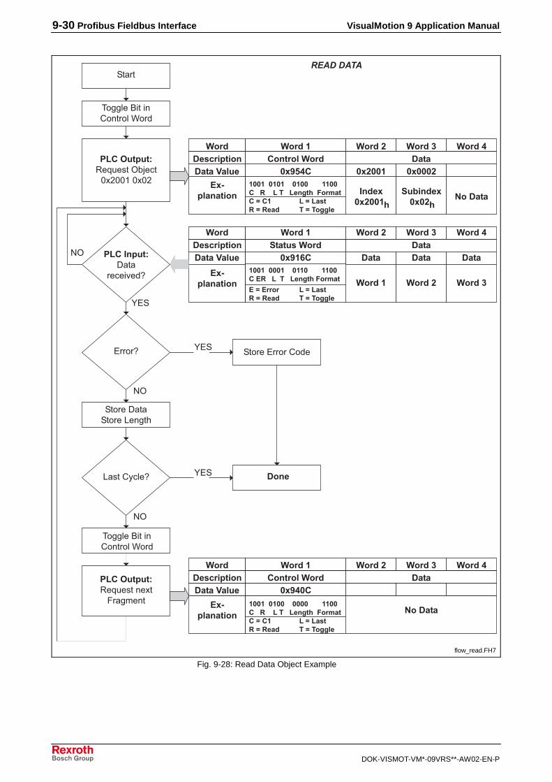
9-30 Profibus Fieldbus Interface VisualMotion 9 Application Manual
DOK-VISMOT-VM*-09VRS**-AW02-EN-P
�$�%�����&�B'��!�04E�<!�A������A��
�$�'����&��!�
��<�#(��D
(�)�� (�)��! (�)��" (�)����������(�)� ����
(�)����*)������
+�� 1$ ���� ���� ��������������
(�)�� ��
��������� (�)��! (�)��" ++ ��+++ ����+ +������� ++$����������������-�.�/�)���
��0��))�) ��0�������0����� ��0���--��
������� ��!��!
� $$)��.#!�#�& �!� )�� ��
(�)�� (�)��! (�)��" (�)���$���)���(�)� ����
(�)����*)������
+����$ +�!++ +�+++!����������
'����+�!++ .
����������� ��2�����
+�+!.�������
++ ��+ + ����+ ++������� ++$�����������������-�.��/�)���$�0�$ ��0�������0����� ��0���--��
��� �D
�! �����!��! ���:��$!�
:��!�&;<)�D
�$�%�����&�B'��!���A!9��$6��!
(�)�� (�)��! (�)��" (�)���$���)���(�)� ����
(�)����*)������
+���+$����������
����������� �������
++ ��+ ++����++++������� ++$�����������������-�.��/�)���$�0�$ ��0�������0����� ��0���--��
� $$)��.#!�#�& �!� )�� ��
�������
�! ������ ��& �����
���
�0
�0
�0
flow_read.FH7
Fig. 9-28: Read Data Object Example

VisualMotion 9 Application Manual Profibus Fieldbus Interface 9-31
DOK-VISMOT-VM*-09VRS**-AW02-EN-P
In some cases, it might be necessary to cancel a data transfer. Torequest a communication reset, the master sends a cancel telegram tothe slave.
(�)�� (�)��! (�)��" (�)���$���)���(�)� ����
(�)����*)������
+�, +/����������
���������
���������
+++��+++ ����++++������� $����������������-�.��/�)���
��0��))�) ��0�������0����� ��0���--��
cancel.FH7
Fig. 9-29: Cancel Telegram
The format byte in the command word is set to Fh. The length byte, the Land the R bits are set to 0.
The slave will set its internal state to expect a new command from themaster.
If the transmission fails, the slave will respond with an error message asshown below. The status word value can be different for writing. Theerror bit in the status word is set and the first word contains a 16-bit errorcode. The toggle bit has the same state as the corresponding requesttelegram.
(�)�� (�)��! (�)��" (�)����������(�)� ����
(�)����*)������
+� �!$ �))�)�*�������������
�����������
+ ��+ ++����++ +������� ++$����������������-�.��/�)���
��0��))�) ��0�������0����� ��0���--��
�������
error.FH7
Fig. 9-30: Error Response from Slave
The error code is two bytes long. The high byte specifies the error classand the low byte contains additional information for the application-specific errors (error class 1Fh).
Parameter Channel Error Codes (High-Byte)Error No.(Hex)
Error Description
0x1F Control-specific error. Refer to Table 9-12 for additional errorinformation, which is based on VisualMotion Serial Port DiagnosticCodes.
0x85 Data length too long (here >128 byte).
0x88 An error occurred during the transmission of data between the PPC-R and the fieldbus slave.
0x8B Format (bits 0-3 of control word) specified is incorrect.
0x8C The length set in control byte greater than Parameter Channel.
0x8D Communication not possible. Parameter Channel too short (<2bytes).
0x90 The format bits (0-3) of the control word were changed whiletransmitting several data blocks.
0x95 A read command was issued, but the length field was set to !=0.
Table 9-11: Parameter Channel Error Codes (High-Byte)
Canceling Data Transfer
Error Messages

9-32 Profibus Fieldbus Interface VisualMotion 9 Application Manual
DOK-VISMOT-VM*-09VRS**-AW02-EN-P
Parameter Channel Error Codes (Low-Byte) for 0x1F
Error No.(Hex)
Error Description
0xF3 Invalid Object Sub Index – Occurs when an attempt to access anincorrect or undefined location in the mapped data area or whenattempting to address a sub index greater than 255.
0xF2 Invalid Object Index – Occurs when attempting to access anincorrect or undefined location in the mapped data area.
0xF1 Not used
0xF0 ASCII Format Error – occurs when attempting to communicate viathe Data Exchange object where VisualMotion ASCII protocol issent. This error also occurs if the initial characters are incorrect(such as the absence of the “>” start character).
Table 9-12: Parameter Channel Error Codes (Low-Byte)
Handling a Data Exchange ObjectWhen mapped objects are not capable of transferring the desired data, aData Exchange Object can be used.
The same procedures for writing and reading mapped objects via ShortFormat 3 apply to the Data Exchange Object.
Selecting a Data Exchange ObjectDepending on the length of a VisualMotion ASCII message, any dataexchange objects can be selected. The entire data length of the dataexchange object, however, must always be transmitted even if theVisualMotion ASCII message is shorter. For example, if you want totransmit an ASCII message of 42 bytes, you must use object 5E72. Toavoid a response error from the fieldbus slave, you must append 22 "Null"characters to the end of the ASCII message to complete a data size of 64bytes.
Note: The checksum for the VisualMotion ASCII protocol is NOTused with the data exchange object. If the checksum is sentas part of the string, it will be ignored, and no checksum will besent in the VisualMotion ASCII response messages. Toensure data integrity, the fieldbus protocols support a low-levelchecksum.
Transmission Sequence via a Data Exchange ObjectFor the data exchange object, two transmission sequences (and tworesponse sequences) are required, to send the read or write message toand then receive the response message from the PPC-R card.

VisualMotion 9 Application Manual Profibus Fieldbus Interface 9-33
DOK-VISMOT-VM*-09VRS**-AW02-EN-P
Short Format 3Control Word
VisualMotion ASCII Protocol
key components:• Object Index #:
data exchangeobject(5E70-5E73).This is thedestination of thedata field. Objectselectiondepends onrequired data fieldsize.
• Subindex #:always = 0 forData ExchangeObject.
key components:• VisualMotion command
(read or write data)
• ASCII data contained in theselected data exchange object
• The <CR> (0x0D) and <LF>(0x0A) characters must beapplied to the ASCII string
• A checksum is not used in thiscase. (Fieldbus has a checksum)
Note: Refer to the VisualMotion 6Reference Manual for an explanationof the VisualMotion ASCII Protocol.
Data Field:
Parameter Channel Message
key components:• fieldbus
command(read or writemessage)
Object Index # Subindex #
Short Format 3 Header
Fig. 9-31: Format of a PK Short Format 3 Message using a Data Exchange Object
The following sequence describes the communication between thefieldbus master (PLC) and the fieldbus slave (PPC-R). For details onreading and writing data in Short Format 3, refer to Messaging Formatson page 9-24.

9-34 Profibus Fieldbus Interface VisualMotion 9 Application Manual
DOK-VISMOT-VM*-09VRS**-AW02-EN-P
VM ASCII protocolcommand text
(read or write data)
PK ResponseReceived?
No
Yes
PK ResponseOK?
No
Yes
No data
PK ResponseReceived?
No
Yes
PK ResponseOK?
No
Yes
VM ASCII protocolresponse text
(write or transmit data)
Message Steps Process Comments
4. Receive ParameterChannel response fromslave.
PK Read Command
PK Write Command1. Write request from themaster with VisualMotionASCII Protocol.
2. Acknowledge ParameterChannel response fromslave.
3. Read request from themaster to get VisualMotionASCII response.
The data field for the writecommand can contain aVisualMotion read or writeprotocol.
The response message containsonly a confirmation that thefieldbus message was sentproperly. Therefore, the size ofthe data field will be 0.
The read request messagecontains only header information(the data field is 0). You mustanticipate the approximate sizeof the data field (VisualMotionASCII response message) inorder to select the appropriatedata exchange object. If theselected object is too short, thedata will be truncated.
The response message willcontain the VisualMotion ASCIIresponse to the VisualMotionASCII command text in Step 1.
Diagnoseerror
Diagnoseerror
Fig. 9-32: Parameter Channel Short Format 3 Procedure, Using DataExchange Object
Accessing Mapped DataRexroth has pre-configured a number of VisualMotion data types to Profibusindexes and subindexes. We call this concept mapped data. These datatypes can be accessed via the Profibus Parameter Channel. The index andsubindex for each of these data types can be calculated using the formulas inTable 9-13 below.

VisualMotion 9 Application Manual Profibus Fieldbus Interface 9-35
DOK-VISMOT-VM*-09VRS**-AW02-EN-P
ObjectIndex # SubIndex # Formula
0x5E73 0x00
Data Exchange Object ---- ----
0x5E70 0x00
0x5E65 0xFF
<FREE> ---- ---- (with SubIndex)
(349 objects available) 0x5D14 0x01
0x5D13 0xFF Index = 0x5D00 + [(Program Integer –1) \ 255]
Program Integers ---- ----
(Int 1 – Int 5100) 0x5D00 0x01 SubIndex = Program Integer – [(Index – 0x5D00) * 255]
0x5CFF 0xFF Index = 0x5CEC + [(Program Float –1)] \ 255]
Program Floats ---- ----
(Float 1 – Float 5100) 0x5CEC 0x01 SubIndex = Program Float – [(Index – 0x5CEC) * 255]
0x5CEB 0xFF
<FREE> ---- ---- (with SubIndex)
(235 objects available) 0x5C01 0x01
0x5C00 0xFF Index = 0x5BF7 + [(Global Integer – 1) \ 512]
Global Integers ---- ----
(GInt 1 – GInt 2550*) 0x5BF7 0x01 SubIndex = Global Integer – [(Index – 0x5BF7) * 512]
0x5BF6 0xFF Index = 0x5BED + [(Global Float – 1) \ 512]
Global Floats ---- ----
(GFloat 1 – Gfloat 2550*) 0x5BED 0x01 SubIndex = Global Float – [(Index – 0x5BED) * 512]
0x5BEC 0xFF
<FREE> ---- ---- (with SubIndex)
(245 objects available) 0x5AF8 0x01
0x5AF7 0xFF Index = 0x5AEE + [(Register – 1) \ 255]
Registers ---- ----
(Reg. 1 – Reg. 2550**) 0x5AEE 0x01 SubIndex = Register – [(Index – 0x5AEE) * 255]
0x5AED 0x04 Index = 0x56F1 + T-Parameter
T-Parameters ---- ----
(T-0-0001 – T-0-1020) 0x56F1 0x01 SubIndex = Task Number
0x56F0 0xFF
<FREE> ---- ---- (with SubIndex)
(241 objects available) 0x5600 0x01
0x55FF 0x01 Index = 0x4800 + C-Parameter
C-Parameters ---- ----
(C-0-0001 - C-0-3583) 0x4801 0x01 SubIndex = 1
0x47FF 0x63 Index = 0x4000 + A-Parameter
A-Parameters ---- ----
(A-0-0001 - A-0-2047) 0x4001 0x01 SubIndex = Axis Number
0x3FFF 0x63 Index = 0x3000 + P-Parameter
P-Parameters ---- ----
(P-0-0001 - P-0-4095) 0x3001 0x01 SubIndex = Drive Number

9-36 Profibus Fieldbus Interface VisualMotion 9 Application Manual
DOK-VISMOT-VM*-09VRS**-AW02-EN-P
ObjectIndex # SubIndex # Formula
0x2FFF 0x63 Index = 0x2000 + S-Parameter
S-Parameters ---- ----
(S-0-0001 - S-0-4095) 0x2001 0x01 SubIndex = Drive Number
0x1FFF ----
<Reserved> ---- ----
0x0000 ----
* current limitation: C-0-0080/C-0-0081 - Maximum number global integers/floats..
**current limitation: first 1024 registers.
Table 9-13: Formulas for Determining Mapped Objects
Example Lookup Tables for Mapped ObjectsThe following is an example lookup table for C-Parameters, when usingmapped objects.
Example Look-up Chart for: C-Parameters CP 0.Y ==> CP = Card Parameter
Y = Parameter Number
Index
0x4801 0x4802 0x4803 …………… 0x48FF 0x4900 …………… 0x55FE 0x55FF
SubIndex = 0x01 CP 0.1 CP 0.2 CP 0.3 CP 0.255 CP 0.256 CP 0.3582 CP 0.3583
Table 9-14: Mapped Object Lookup Table for C-Parameters
The following is an example lookup table for A-Parameters, when usingmapped objects. The same formula also applies to SERCOS (S) andTask (T) Parameters.
Example Look-up Chart for: A-Parameters AP X.Y ==> AP = Axis Parameter
X = Axis Number
Y = Parameter Number
Index
0x4001 0x4002 0x4003 ……………
0x40FF 0x4100 …………… 0x47FE 0x47FF
0x01 AP 1.1 AP 1.2 AP 1.3 AP 1.255 AP 1.256 AP 1.2046 AP 1.2047
SubIndex = 0x02 AP 2.1 AP 2.2 AP 2.3 AP 2.255 AP 2.256 AP 2.2046 AP 2.2047
0x03 AP 3.1 AP 3.2 AP 3.3 AP 3.255 AP 3.256 AP 3.2046 AP 3.2047
: : : : : : : : : :
: : : : : : : : : :
0x28 AP 40.1 AP 40.2 AP 40.3 AP 40.255 AP 40.256 AP 40.2046 AP 40.2047
Table 9-15: Mapped Object Lookup Table for A-Parameters
Card (C) Parameters
Axis(A) Parameters

VisualMotion 9 Application Manual Profibus Fieldbus Interface 9-37
DOK-VISMOT-VM*-09VRS**-AW02-EN-P
The following is an example lookup table for P-Parameters, when usingmapped objects.
Example Look-up Chartfor:
P-Parameters PP X.Y ==> PP = SERCOS P-Parameter (set 0 only)
X = Drive Number
Y = Parameter Number
Index = (Class ID && Instance ID for DeviceNet)
C118, In1 C118, In2 C118, In3 …………… C118, In255 C119, In1 …………… C134, In14 C134, In15
0x3001 0x3002 0x3003 …………… 0x30FF 0x3100 …………… 0x3FFE 0x3FFF
0x01 PP 1.1 PP 1.2 PP 1.3 PP 1.255 PP 1.256 PP 1.4094 PP 1.4095
SubIndex = 0x02 PP 2.1 PP 2.2 PP 2.3 PP 2.255 PP 2.256 PP 2.4094 PP 2.4095
(Attribute ID 0x03 PP 3.1 PP 3.2 PP 3.3 PP 3.255 PP 3.256 PP 3.4094 PP 3.4095
for DNet) : : : : : : : : : :
: : : : : : : : : :
0x28 PP 40.1 PP 40.2 PP 40.3 PP 40.255 PP 40.256 PP 40.4094 PP 40.4095
Table 9-16: Mapped Object Lookup Table for P-Parameters
The following is an example lookup table for Integers, when usingmapped objects. The same formula also applies to Floats, GlobalIntegers, Global Floats and Registers.
Example Look-up Chart for: VM Program Integers PI 0.Y ==> PI = Program Integer
Y = Program Integer Number
Index
0x5D00 0x5D01 0x5D02 …………… 0x5D13
0x01 PI 1 PI 256 PI 511 PI 4846
SubIndex = 0x02 PI 2 PI 257 PI 512 PI 4847
0x03 PI 3 PI 258 PI 513 PI 4848
: : : : : :
: : : : : :
0xFF PI 255 PI 510 PI 765 PI 5100
Table 9-17: Mapped Object Lookup Table for Integers
Product-Specific (P) Parameters
Integers

9-38 Profibus Fieldbus Interface VisualMotion 9 Application Manual
DOK-VISMOT-VM*-09VRS**-AW02-EN-P

VisualMotion 9 Application Manual DeviceNet, ControlNet, and EtherNet/IP Fieldbus Interfaces 10-1
DOK-VISMOT-VM*-09VRS**-AW02-EN-P
10 DeviceNet, ControlNet, and EtherNet/IP FieldbusInterfaces
10.1 General Information
Version Note:Information in this document is based on VisualMotion Toolkitsoftware version 09VRS and PPC-R firmware versionGPP09VRS (for DeviceNet, ControlNet, and EtherNet/IP).GMP09VRS firmware does not have a fieldbus interface, but canbe used with the Rexroth PPC-PCI bus interface to allow cyclicand non-cyclic data transfer.
VisualMotion 9 software is downward compatible with GPP firmware, but,depending on the hardware platform selected, the type of fieldbuscommunication selection may be limited. The following table lists thefieldbus firmware versions and the available fieldbus interfaces for eachversion.
FieldbusInterfaces
PPC-RGPP07VRS
PPC-RGPP08VRS
PPC-RGPP09VRS
PPC-PGMP09VRS
DeviceNet • • • ControlNet • • EtherNet/IP •
NoFieldbusSupport
Table 10-1: Fieldbus Firmware Version and Interface Type
Note: For detailed fieldbus hardware information, refer to theVisualMotion 9 Project Planning Manual.
PPC-R System Description with a FieldbusThe PPC-R can operate on a serial fieldbus interface (network) by meansof a fieldbus expansion card that communicates with the PPC-R via dual-port RAM. The function of the fieldbus card, which is similar to that of anetwork card in a PC, allows communication with other devices on thenetwork.
Fig. 10-1 illustrates the fieldbus slave and master interface in a system.In this document, we will refer to the PLC as the fieldbus master and thePPC-R as the fieldbus slave.

10-2 DeviceNet, ControlNet, and EtherNet/IP Fieldbus Interfaces VisualMotion 9 Application Manual
DOK-VISMOT-VM*-09VRS**-AW02-EN-P
����� ���
��
��
����
��
"�
��
��
����
�� ����#
$%��& & ���$%�
����'�'�'�(�(�
�'�"
����"
���
�� ��
�
��
��#(�
��#(�
280
9#�)�4'�+��!��
/:&
9#�)�4'��&;<)#<& 66'�#<�!# �
9#�)�4'���)�(�=��(#<���!� ��& �!� )��!>
& 66'�#<�!# ��4�!%���//&?�����*#�)�4'�(#���'�)?" �!��+
= "��!����!�@��(��;���6�>
��&0�
PPCR_02_devicenet_sercos.FH7
Fig. 10-1: Sample Master/Slave Setup with Fieldbus Card
With the PPC-R, the fieldbus card can be used only as a slave card in amaster/slave setup.
Note: When using an EtherNet/IP type fieldbus card in aVisualMotion 9 system, no other fieldbus interface (i.e.,Profibus, DeviceNet, ControlNet, Interbus) or MTS-R PLCinterface can be used.
It is still possible to communicate with GPP 9 firmware overthe same network from VisualMotion 9 Toolkit with EtherNet/IPfieldbus communication enabled. Only one ethernet card inthe control is required for communication with bothEtherNet/IP fieldbus interface and ethernet network interface
The VisualMotion Fieldbus MapperIn the VisualMotion software package, the Fieldbus Mapper is a tool usedto set up fieldbus configuration and data mapping.
Fieldbus hardware platform selections are made through the FieldbusMapper window with VisualMotion Toolkit in Service Mode. To select theFieldbus hardware platform:
1. Open VisualMotion in Service Mode, indicated by the service modesymbol ( ) in the lower right corner of the VisualMotionToolkit window.
2. Select Commission ⇒ Fieldbus Mapper to open the FBMapperwindow.
3. Click or select File ⇒ New to open the Fieldbus Slave Definitionwindow.
When a hardware platform is selected, only the fieldbus types availablefor that platform can be selected, see Table 10-1.

VisualMotion 9 Application Manual DeviceNet, ControlNet, and EtherNet/IP Fieldbus Interfaces 10-3
DOK-VISMOT-VM*-09VRS**-AW02-EN-P
Data Transfer Direction (Output vs. Input)In the VisualMotion Fieldbus Mapper, output and input are alwaysdescribed with respect to the fieldbus master. The definitions for outputand input follow:
output: the communication from the PLC to the PPC-R (i.e. from thefieldbus master to the fieldbus slave).Synonyms for this type of communication: send or write data.
input: the communication from the PPC-R to the PLC (i.e. from thefieldbus slave to the fieldbus master).Synonyms for this type of communication: receive or read data.
Fieldbus Data Channel DescriptionsThe Rexroth DeviceNet, ControlNet, and EtherNet/IP fieldbus interfacecards for the PPC-R support the following communication channels:
• Cyclic Channel: Polled I/O (for single and multiplex channels)
• Non-Cyclic Channel: Explicit Messaging
Cyclic (Polled I/O) ChannelCyclic data is user-defined. It is stored in two ordered lists (C-0-2600 forinput data, C-0-2601 for output data) and transmitted serially over the bus.In the cyclic channel, data is updated cyclically between the fieldbusmaster and slave.
The cyclic data channel is limited to 64 input words and 64 output words.PPC-R data types consume these words in either one-word (or 16-bit)groups for PPC-R registers or two-word (or 32-bit) groups for all otherdata types.
The PPC-R mapping list is scanned every 4 ms and data is sent andreceived to/from the fieldbus slave board's dual port RAM.
The cyclic data channel can be made up of any combination of thefollowing data types:
• single
• multiplex
Cyclic (Polled I/O) Channel
Single Channel Only
word 31 word 0
Cyclic (Polled I/O) Channel
word 0word 31
Multiplex Channel Single Channel
Cyclic (Polled I/O) Channel
Multiplex Channel Only
word 31 word 0
Fig. 10-2: Configuration Options for the Cyclic Data Channel

10-4 DeviceNet, ControlNet, and EtherNet/IP Fieldbus Interfaces VisualMotion 9 Application Manual
DOK-VISMOT-VM*-09VRS**-AW02-EN-P
Cyclic Data: Types and SizesThe following table outlines the PPC-R data types that can be transmittedvia the cyclic channel and the amount of space (in 16-bit words) that eachdata type consumes.
Note: The cyclic data mapping lists support only 16- and 32-bit data ofthe following types for reading and writing:- Integer- Float- Binary (used in PPC-R parameters)- Hex (used in PPC-R parameters)For all other data types (e.g. diagnostic messages - “strings”), useExplicit Messaging.
PPC-R Data Type Data Size(in 16-Bit Words)
Register 1
Program Integer (currently active program ONLY *) 2
Program Float (currently active program ONLY *) 2
Global Integer 2
Global Float 2
Card Parameter 2
Axis Parameter 2
Task Parameter 2
Note: Drive parameters "S" or "P" cannot be transmitted cyclically becauseof the inherent delay of parameter access over the SERCOS service channel.However, if a drive parameter is mapped to an Axis Parameter, that Axisparameter could be used in cyclic data (see description of Axis Parameters180-196 in the VisualMotion Functional Description).
* Important Note: Integers and floats are shown only for the currentlyactive program. Each time you activate a new progam, the fieldbusreads/writes to the newly-activated program.
Table 10-2: PPC-R Cyclic Data Types and Sizes
Single Data TypesSingle data types are mapped directly in the cyclic mapping ordered lists (C-0-2600, C-0-2601).
Multiplex Data Types(Cyclic Data Channel)In some multi-axis applications, 64 words of cyclic data transfer are notsufficient to meet the requirement of the application.
When insufficient data transfer space is available, multiplex data can beset up within the cyclic channel. One multiplex container acts as aplaceholder for multiple possible PPC-R data types (all of the same wordsize). The currently transmitted PPC-R data type is based on an indexvalue placed in a multiplex control or status word attached to the end ofthe cyclic list. Depending on the index specified by the master, themultiplex channel permits a different set of data within the cyclic channelto be transferred as current real-time data. Multiplex containers can beadded to the input and output lists separately and the input and outputindexes can be designated separately (in the control and status words).
Note: Using the multiplex channel reduces the maximum number ofusable words for storing PPC-R data to 63. The 64th word (orlast used word, if fewer than 64 words) is used as the multiplexentry control/status word.

VisualMotion 9 Application Manual DeviceNet, ControlNet, and EtherNet/IP Fieldbus Interfaces 10-5
DOK-VISMOT-VM*-09VRS**-AW02-EN-P
Note: When using VisualMotion 9 with GPP 7 firmware, a maximumof 15 multiplex containers and a maximum of 180 mappingitems can be transmitted in the input or output list. Thislimitation of mapping objects means that you cannot multiplexall 15 containers with all 32 available indexes (=480 items).For VisualMotion 9 with GPP 8 or 9 firmware, there is nolimitation for multiplexing (each of the first 63 words may bemultiplexed with up to 32 indexes).
Index 0 Index 0 Index 0 Index 0 Index 0
Index 1 Index 1 Index 1 Index 1 Index 1
Index 2 Index 2 Index 2 Index 2 Index 2...
Index 31 Index 31 Index 31 Index 31 Index 31
multiplex containermultiplex
control/statusword
multiplex containercontainer
16-bit 16-bit 16-bit 32-bit 32-bit
multiplex container
32-bit
multiplexcontainer . . . single item
32-bit
Word 63 Word 0
single item
32-bit 16-bit
singleitem
16-bit
singleitem
Word 1Word 2Word 3Word 4Word 5. . .Word 55Word 56Word 57Word 58Word 59Word 60Word 61Word 62
.
.
.
.
.
.
.
.
.
.
.
.
multiplex
Fig. 10-3: Sample Command (PLC⇒PPC-R) or Response (PPC-R ⇒PLC)
The multiplex control and status words serve to command andacknowledge multiplex data transferred between the fieldbus master andthe fieldbus slave. The control word is associated with outputcommunication (PLC⇒PPC-R). The status word is associated withinput communication (PPC-R⇒PLC). Single data items are not affectedby the multiplex control and status words.
Note: For specific information about how the fieldbus master usesthe multiplex control and status words, refer to Multiplexing onpage 10-22.
Multiplex Control and StatusWords

10-6 DeviceNet, ControlNet, and EtherNet/IP Fieldbus Interfaces VisualMotion 9 Application Manual
DOK-VISMOT-VM*-09VRS**-AW02-EN-P
/:&
�+�6
�;
/:&
�+�6
�;
/:&
�+�6
�;
&;<)#<�&�����)
&;<)#<�&�����)
&;<)#<�&�����)
2���A��� 2���A��� 2���A���
���% ����� �?6
')!#")�A�����!�
���% ����� �?6
')!#")�A�����!�
���% ����� �?6
')!#")�A�����!�
+')!#")�A#�$< �!� )�8��!�!'�% ��
+')!#")�A& �!�#�����+')!#")�A& �!�#�����+')!#")�A& �!�#�����
+')!#")�A& �!�#�����+')!#")�A& �!�#�����+')!#")�A& �!�#�����
+')!#")�A& �!�#�����+')!#")�A& �!�#�����+')!#")�A& �!�#�����
�������� ��������! ��������"
multiplexing.FH7
Fig. 10-4: Examples for Reading Data via the Multiplex Channel
Non-Cyclic Channel (Explicit Messaging)The non-cyclic channel is used for data that needs to be transferred onlyonce or sporadically, such as:
• the transmission of lists
• parameterization of axes or programs
Instead of being updated during each cycle, non-cyclic data is transferredusing a command initiated by the master. Though any data type can betransferred non-cyclically, diagnostic messages and drive parameters(S and P) must be transferred non-cyclically because of the non-cyclicretrieval for drive parameters through SERCOS and the length of thediagnostic messages.
There are two types of non-cyclic data transmissions for the PPC-R/VisualMotion system:
• mapped data (directly to PPC-R data types)
• data exchange object
Non-cyclic data can be accessed via Explicit Messaging support of theFieldbus master.
Mapped DataMapped data is the most powerful feature of the PPC-R non-cyclicfieldbus interface. Through mapped data, the user has access to virtuallyevery PPC-R parameter over the fieldbus. It is easy to implement fromthe PLC side and requires no setup on the PPC-R side.

VisualMotion 9 Application Manual DeviceNet, ControlNet, and EtherNet/IP Fieldbus Interfaces 10-7
DOK-VISMOT-VM*-09VRS**-AW02-EN-P
Data Exchange ObjectsFour data exchange objects Class 100, Instance 1-4, Attribute 100 areavailable for the transfer of non-cyclic data. These objects represent fixeddata "containers" of varying lengths that transfer the VisualMotion ASCIIProtocol to the PPC-R card, in the same way that data is transferred usingthe VisualMotion ASCII Format via an Explicit Message. These objectsserve as an open-ended possibility to access any VisualMotion data(including cams, diagnostic text, etc.), but more work is required in themaster to perform a transmission of this type. For more specific informationabout these objects, refer to Data Exchange Objects on page 10-33.
10.2 Fieldbus Mapper Functionality
Initializing the Fieldbus Mapper from VisualMotion 91. Open an existing program or create a new program. You must be
using PPC-R hardware with GPP firmware to use the FieldbusMapper described in this document.
2. Select Commission ⇒ Fieldbus Mapper. The main FieldbusMapper window is displayed (refer to Fig. 10-5 below).
FB_Mapper_New.tif
Fig. 10-5: FBMapper – Project Window
Creating a New Fieldbus Mapper FileTo create a Fieldbus Mapper file:
1. Click or select File ⇒ New.A “setup wizard” goes through three steps:
• Fieldbus Slave Definition
• Fieldbus Slave Configuration
• Cyclic Data Configuration
2. Enter the information requested in the setup windows. For moredetails on each step, refer to Fieldbus Slave Definition, Fieldbus SlaveConfiguration, and Cyclic Data Configuration for detailed informationabout each configuration step.
3. Save the file (automatically has a .prm extension).
To Add/Insert, Edit, or Delete an item in a file, open the SelectedMapping List menu from the Edit menu (refer to Fig. 10-6 below). Formore information about each step, refer to Fieldbus Slave Definition,Fieldbus Slave Configuration, and Cyclic Data Configuration for detailedinformation about each configuration step.

10-8 DeviceNet, ControlNet, and EtherNet/IP Fieldbus Interfaces VisualMotion 9 Application Manual
DOK-VISMOT-VM*-09VRS**-AW02-EN-P
FB_Mapper_Edit_Menu.tif
Fig. 10-6: Fieldbus Mapper Edit Menu
Note: You can also directly add, insert, delete, edit an item, or create anew list by:
• clicking on the item to be edited in the main Fieldbus Mapperwindow and selecting the desired function under Edit⇒ Selected Mapping List
OR
• right-clicking on an item to display a menu of functions
Importing a Fieldbus Mapper FileA Fieldbus Mapper file can be imported from another project. To importthe file:
1. Select File ⇒ Import.
2. Browse to find the desired file (*.prm extension).
3. Click Open. The main Fieldbus Mapper window appears, which liststhe configuration information. Refer to Fig. 10-7 below.

VisualMotion 9 Application Manual DeviceNet, ControlNet, and EtherNet/IP Fieldbus Interfaces 10-9
DOK-VISMOT-VM*-09VRS**-AW02-EN-P
FB_Mapper_Main_DN.tif
Fig. 10-7: Fieldbus Mapper Main Window (Complete)
Fieldbus Slave DefinitionFrom the Fieldbus Slave Definition window, select the desired HardwarePlatform and DeviceNet, ControlNet or Ethernet/IP as the FieldbusType (refer to Fig. 10-8 below). Refer to Table 10-1 for a list of theavailable hardware platforms for the fieldbus types. The hardwareplatform can only be selected when the project is in Service mode.

10-10 DeviceNet, ControlNet, and EtherNet/IP Fieldbus Interfaces VisualMotion 9 Application Manual
DOK-VISMOT-VM*-09VRS**-AW02-EN-P
FB_Slave_Def.tif
Fig. 10-8: Fieldbus Slave Definition Window

VisualMotion 9 Application Manual DeviceNet, ControlNet, and EtherNet/IP Fieldbus Interfaces 10-11
DOK-VISMOT-VM*-09VRS**-AW02-EN-P
Fieldbus Slave ConfigurationThe Fieldbus Slave Configuration windows for DeviceNet and ControlNetare shown in figure Fig. 10-9 below.
ControlNet
DeviceNet
FB_Slave_Config.tif
Fig. 10-9: Fieldbus Slave Configuration
• MAC ID (0-63 for DeviceNet, 1-99 for ControlNet): set to a uniquenumber for this device on the bus.
• Baud Rate (DeviceNet only): set to match that of the master.
Set the Error Reaction to Shutdown (default), Warning or Ignore. Refer toFieldbus Error Reaction on page 10-20 for detailed information abouteach setting.
The Advanced Options: are shown only if the checkbox next to ShowAdvanced Configuration Options is checked (refer to Fig. 10-11 below).In most cases, the default options should apply.
The Fieldbus Slave Configuration window for EtherNet/IP is shown below:
Standard Fieldbus ConfigurationOptions
Fieldbus Error Reaction
Advanced Configuration Options

10-12 DeviceNet, ControlNet, and EtherNet/IP Fieldbus Interfaces VisualMotion 9 Application Manual
DOK-VISMOT-VM*-09VRS**-AW02-EN-P
EtherNet/IP
EtherNetIP_IP_Address.tif
Fig. 10-10: Fieldbus Slave Configuration for EtherNet/IP
Selecting On for the EtherNet/IP interface will allow the control todistinguish between EtherNet/IP and standard ethernet duringcommunication when both are being used.
Specify whether the control is running in Half Duplex or Full Duplexmode.
Note: Using an ethernet switch and running in Full Duplex mode isrecommended. Manual configuration of ports is required asthe ethernet card does not support auto negotiation.
Set the Error Reaction to Shutdown (default), Warning or Ignore. Refer tothe Fieldbus Error Reaction on page 10-20 for detailed information abouteach setting.
The Advanced Options: are shown only if the checkbox next to ShowAdvanced Configuration Options is checked (refer to Fig. 10-12 below).In most cases, the default options should apply.
EtherNet/IP Interface
Mode
Fieldbus Error Reaction
Advanced Configuration Options

VisualMotion 9 Application Manual DeviceNet, ControlNet, and EtherNet/IP Fieldbus Interfaces 10-13
DOK-VISMOT-VM*-09VRS**-AW02-EN-P
DeviceNet
ControlNet
FB_Slave_Config_Adv.tif
Fig. 10-11: Fieldbus Slave Configuration: Advanced
• Swapping: If word and byte swapping is required by your PLC, selectthe checkboxes next to “Swap Bytes” and “Swap Words." Bytes andwords are not swapped if the boxes are left unchecked. Refer toWord and Byte Swapping on page 10-22.
Note: When the Allen-Bradley 1747-SDN (DeviceNet Scanner)Module for the SLC-Series PLC is used, both Swap Bytes andSwap Words can be checked, so the order of resulting dataappears correctly.
• Multiplex Method: select Primary or Secondary (Primary is thedefault). Select Secondary only if you have an inconsistent fieldbusmaster. Refer to Multiplexing on page 10-22 for detailed informationabout each method.

10-14 DeviceNet, ControlNet, and EtherNet/IP Fieldbus Interfaces VisualMotion 9 Application Manual
DOK-VISMOT-VM*-09VRS**-AW02-EN-P
EtherNet/IP
EtherNet_IP_Address_Adv.tif
Fig. 10-12: Fielbus Slave Configuration: Advanced, for EtherNet/IP
Cyclic Data ConfigurationAn example of the Cyclic Data Configuration window is shown in Fig. 10-13 below. If you are editing an existing Fieldbus Mapper file, the list willprobably contain more items.
First, you must select the Cyclic Input List (from PPC-R to PLC) or theCyclic Output List (from PLC to PPC-R).
Cyclic_Data_Config.tif
Fig. 10-13: Cyclic Data Configuration
Adding an Item to the List1. Select the Cyclic Input List or the Cyclic Output List.
2. Click Add. The window in Fig. 10-14 appears. Select the Data Type(for example, Register).
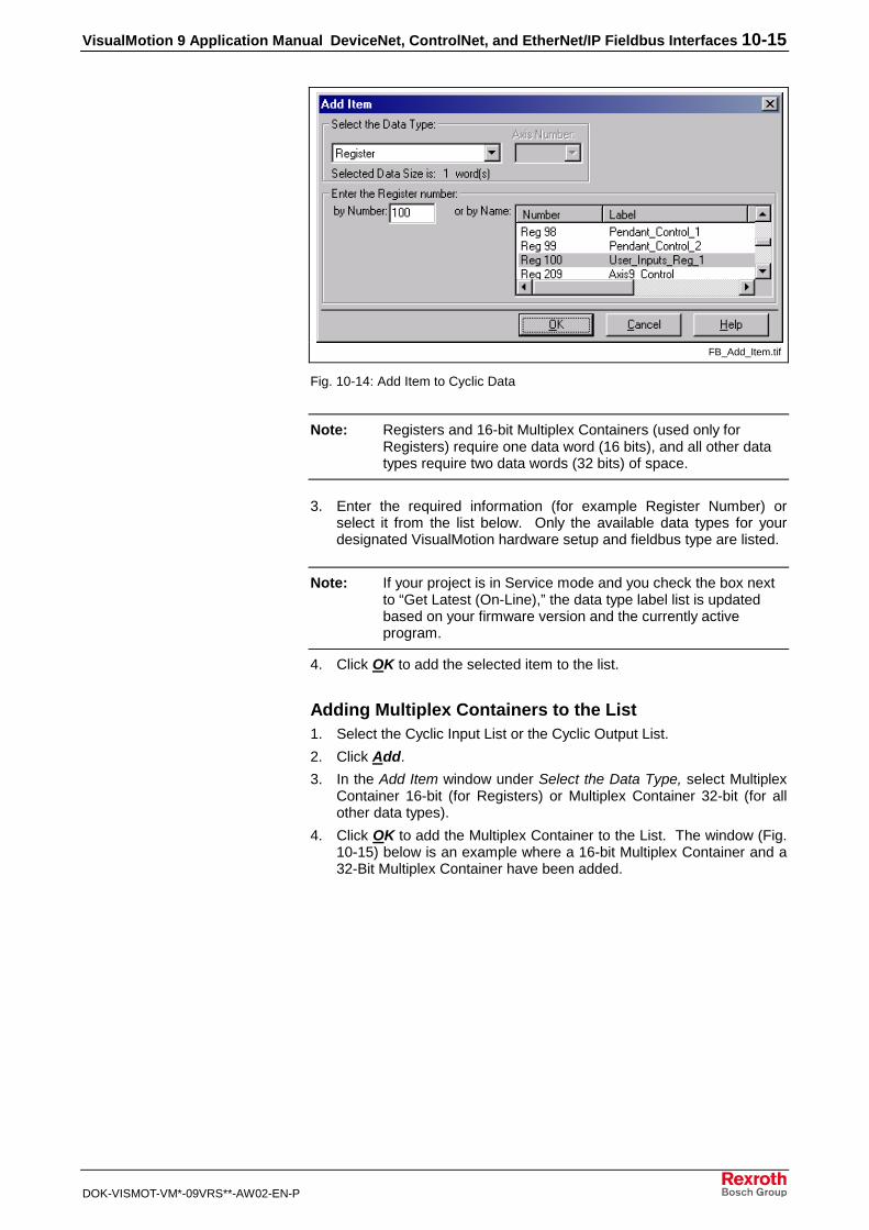
VisualMotion 9 Application Manual DeviceNet, ControlNet, and EtherNet/IP Fieldbus Interfaces 10-15
DOK-VISMOT-VM*-09VRS**-AW02-EN-P
FB_Add_Item.tif
Fig. 10-14: Add Item to Cyclic Data
Note: Registers and 16-bit Multiplex Containers (used only forRegisters) require one data word (16 bits), and all other datatypes require two data words (32 bits) of space.
3. Enter the required information (for example Register Number) orselect it from the list below. Only the available data types for yourdesignated VisualMotion hardware setup and fieldbus type are listed.
Note: If your project is in Service mode and you check the box nextto “Get Latest (On-Line),” the data type label list is updatedbased on your firmware version and the currently activeprogram.
4. Click OK to add the selected item to the list.
Adding Multiplex Containers to the List1. Select the Cyclic Input List or the Cyclic Output List.
2. Click Add.
3. In the Add Item window under Select the Data Type, select MultiplexContainer 16-bit (for Registers) or Multiplex Container 32-bit (for allother data types).
4. Click OK to add the Multiplex Container to the List. The window (Fig.10-15) below is an example where a 16-bit Multiplex Container and a32-Bit Multiplex Container have been added.

10-16 DeviceNet, ControlNet, and EtherNet/IP Fieldbus Interfaces VisualMotion 9 Application Manual
DOK-VISMOT-VM*-09VRS**-AW02-EN-P
Cyclic_Data_Config_mltplx.tif
Fig. 10-15: Cyclic Data Configuration, Multiplex Containers
Note: At this point, the Multiplex Containers do not yet contain anyitems. To add multiplex items refer to Adding Items to anEmpty Multiplex Container below.
Adding Items to an Empty Multiplex Container1. In the Cyclic Data Configuration window, select the multiplex
container to which you want to add items.
2. Click Add. The window in Fig. 10-16 below appears. Because it isunclear whether you would like to add to the list or to the multiplexcontainer, the Fieldbus Mapper is requesting clarification.
Add_Multiplex.tif
Fig. 10-16: Add Item or Multiplex Item Window
Note: For subsequent items, highlight any of the indexes within themultiplex container before clicking Add, and the Fieldbus Mapper willknow you want to add to that container.
3. To add to the selected multiplex container, click No. The window inFig. 10-17 below is an example for adding a 32-bit multiplex item.
4. Select the desired item to be added to the multiplex container.

VisualMotion 9 Application Manual DeviceNet, ControlNet, and EtherNet/IP Fieldbus Interfaces 10-17
DOK-VISMOT-VM*-09VRS**-AW02-EN-P
Note: In addition to the data types that can be added to the multiplexlist, an empty item called Multiplex Empty Item is available tofill a space within the multiplex container, if nothing is to bemapped to a particular index.
5. Click OK. The item is automatically placed in the multiplex containeras the next unassigned index item (e.g. the first item is index 00, thelast is index 31).
6. Repeat for as many items as you want to add to the multiplexcontainer, up to 32 items.
Add_Multiplex_Item.tif
Fig. 10-17: Adding a Multiplex Item to the Container (32-bit example)
Editing the Cyclic Data ListsTo make changes to an existing list, use the following buttons:
Button Function
Inserts a new item at the end of the list.
Inserts a new item into the list directly before the selected item.
Removes the selected item from the list.
Allows editing of the selected item. (To edit a list item, you mayalso double-click on it.)
Clears up the current list.
Table 10-3: Button Functions in the Cyclic Data Configuration Window
Additional FunctionsSeveral additional functions are available in the Fieldbus Mapper:
Menu Item Function
Print Print the current fieldbus configuration data.
Print Preview Preview the printout of the current fieldbusconfiguration data
Print Setup Configure printer settings
Table 10-4: Additional Functions

10-18 DeviceNet, ControlNet, and EtherNet/IP Fieldbus Interfaces VisualMotion 9 Application Manual
DOK-VISMOT-VM*-09VRS**-AW02-EN-P
Getting the Fieldbus Configuration from the PPCAfter getting the fieldbus configuration from the PPC, the followinginformation is detected by the system and appears in the configurationlist:
• Fieldbus Type Found
• Fieldbus FW (Firmware) Version
• GPP Control FW (Firmware) Version
An example is shown in Fig. 10-18 below. For ControlNet and EtherNet/IPfieldbuses, the configuration tree would have different elements in it.
On-line Information
on-line info_DN.tif
Fig. 10-18: On-Line Fieldbus Configuration Information (DeviceNet Example)

VisualMotion 9 Application Manual DeviceNet, ControlNet, and EtherNet/IP Fieldbus Interfaces 10-19
DOK-VISMOT-VM*-09VRS**-AW02-EN-P
10.3 Information for the GPP Programmer
Fieldbus StatusVisualMotion Register 19 holds the information for "Fieldbus Status." Theregister information can be referenced in a VisualMotion applicationprogram to respond to the status of each bit. The use of these bits isapplication-dependent.
Table 10-5 below contains the bit assignment for the fieldbus status. Theassigned bits are labeled with "x" and the bit number in the second row.Unassigned bits are labeled with "---."
16 15 14 13 12 11 10 9 8 7 6 5 4 3 2 1
--- x15 --- --- --- --- --- --- --- --- --- x5 x4 --- x2 x1
Table 10-5: Bit Assignment for VisualMotion Register 19
Bit DefinitionsStatus bits for the internal DPR (Dual-Port RAM) communication betweenthe fieldbus slave and the PPC-R:
x1: FB Init OK , LSB (least significant bit)
x2: FB Init OK, MSB (most significant bit)
The bit combinations for x1 and x2 are as follows:
Bit 2(PPC-R)
Bit 1(Fieldbus)
Description
0 0 A reset has been executed on the DPR,orneither the PPC-R nor the fieldbus card haveinitialized the DPR.
0 1 The DPR is initialized by the fieldbus card, but notyet by the PPC-R.
1 0 The DPR initialization is complete. DPR has beeninitialized by the fieldbus card and PPC-R. Fieldbusto PPC-R communications system is ready.
1 1 Fieldbus to PPC-R communications system is ready.
Table 10-6: Possible Settings for Bits 1 and 2, Status Bits for DPRCommunication
Status bit for the active bus capabilities of the fieldbus slaves (FB SlaveReady)
0--> The fieldbus slave is not (yet) ready for data exchange.
1--> The fieldbus slave can actively participate on the bus.
Status bit for the non-cyclic channel (Explicit Messaging) (Non-CycReady)
0--> The non-cyclic channel (Explicit Messaging) cannot (yet) be used.
1--> The non-cyclic channel (Explicit Messaging) is ready for use by thefieldbus master.
Status bit for the cyclic data output (Cyclic Data Valid):
0--> The cyclic data outputs (coming in to the PPC-R) are INVALID.
1--> The cyclic data outputs (coming in to the PPC-R) are VALID. Thesystem looks for this bit to be 1 before allowing data transfer.
This bit is monitored for the Fieldbus Error Reaction. Whenever this bitgoes to 0 after a fieldbus card was initially found by the PPC-R, theselected Error Reaction (system shutdown, error message, or ignore) is
x1, x2
x4
x5
x15

10-20 DeviceNet, ControlNet, and EtherNet/IP Fieldbus Interfaces VisualMotion 9 Application Manual
DOK-VISMOT-VM*-09VRS**-AW02-EN-P
initiated. Refer to Fieldbus Error Reaction on page 10-20 for anexplanation of the Fieldbus Error Reaction setting.
Fieldbus DiagnosticsVisualMotion Register 20 holds the information for "Fieldbus Diagnostics."
Table 10-7 below contains the bit assignment for the diagnostics. Theassigned bits are labeled with "x" and the bit number in the second row.Unassigned bits are labeled with "---."
16 15 14 13 12 11 10 9 8 7 6 5 4 3 2 1
X16 x15 x14 x13 --- --- --- --- --- --- --- --- --- --- --- ---
Table 10-7: Bit Assignment for VisualMotion Register 20
Bit DefinitionsIdentification of the fieldbus interface card (FB Card Found)
The bit combinations for x13, x14 and x15 are as follows:
Bit 16 Bit 15 Bit 14 Bit 13 Fieldbus Type
0 0 0 0 <NO CARD>
0 0 0 1 <Not Defined>
0 0 1 0 Interbus
0 0 1 1 DeviceNet
0 1 0 0 Profibus
0 1 0 1 ControlNet
0 1 1 0 <Not Defined>
0 1 1 1 EtherNet/IP (10 MB)
1 1 1 1 Indramat PLC Interface
Table 10-8: Identification of the Fieldbus Interface
Fieldbus/PLC Cyclic Read/Write MonitoringMonitoring of Fieldbus read/write capabilities to the cyclic channel areassociated with three parameters:
• C-0-2611 Fieldbus/PLC Cyclic Channel: Current Number of Misses–displays the current number of transfers to/from the cyclic channel.
• C-0-2612 Fieldbus/PLC Cyclic Channel: Peak Number of Misses –displays the maximum number of missed transfers to/from the cyclicchannel.
• C-0-2613 Fieldbus/PLC Cyclic Channel: Timeout Counter – displaysthe number of timeouts in the cyclic channel. If after 4 ms, the CyclicMapping Lists are not successfully transmitted, a "miss" is noted.
For more information about these parameters, see the VisualMotion 9Functional Description manual.
Fieldbus Error Reaction
Note: The Fieldbus Error Reaction setting is active only in SERCOSPhase 4. In all other SERCOS phases, it will be inactive.
You can select how you would like the PPC-R system to react in case of afieldbus error. This reaction can be set in the "Fieldbus SlaveConfiguration" window, using the combo box labeled "Fieldbus ErrorReaction."
x13 - x16

VisualMotion 9 Application Manual DeviceNet, ControlNet, and EtherNet/IP Fieldbus Interfaces 10-21
DOK-VISMOT-VM*-09VRS**-AW02-EN-P
Three options are available for the Error Reaction setting. Depending onthe selected setting, the value 0, 1, or 2 is stored in Parameter C-0-2635:
Setting Value in Parameter C-0-2635
Shutdown 0 (default)
Warning Only 1
Ignore 2
Table 10-9: Parameter C-0-2635 Values for Error Reaction Settings
Fieldbus Mapper TimeoutThe Fieldbus Mapper continually scans the system for sufficientresources to process the cyclic data mapping lists (2600 and 2601 lists).If 10 out of 10 consecutive attempts of the mapping list update areincomplete, the system is considered to have insufficient resources andthe selected error reaction is evoked, as follows:
If "Shutdown" (0) is set in Parameter C-0-2635, the following error isgenerated from the PPC-R card: 520 Fieldbus Mapper Timeout
If "Warning Only" (1) is set in Parameter C-0-2635, the following error isgenerated: 209 Fieldbus Mapper Timeout
If "Ignore" (2) is set in Parameter C-0-2635, the system will update asresources become available, but there is no way to monitor whether or notupdates actually occur.
Lost Fieldbus ConnectionRegister 19, bit 4 indicates the status of the fieldbus. Refer to FieldbusStatus for more specific bit information. The system monitors this bit andevokes the selected error reaction if the bit is low (0), after a fieldbus cardis found. A typical situation that will cause this condition is thedisconnection of the fieldbus cable from the fieldbus card.
If "Shutdown" (0) is set in Parameter C-0-2635, the following error isgenerated from the PPC-R (active in SERCOS Phase 4 only):519 Lost Fieldbus Connection
If "Warning Only" (1) is set in Parameter C-0-2635, the following error isgenerated (active in SERCOS Phase 4 only):208 Lost Fieldbus Connection
If "Ignore" (2) is set in Parameter C-0-2635, there is no noticeablereaction when the Register 19 status bits go low, unless the GPPapplication program is customized to evoke a special reaction.
Troubleshooting Tip:
If a fieldbus card is not found on the system, the ErrorReaction setting will be ignored. If you have a fieldbus cardand the Error Reaction is not responding as expected, thesystem may not "refer to" your fieldbus card.
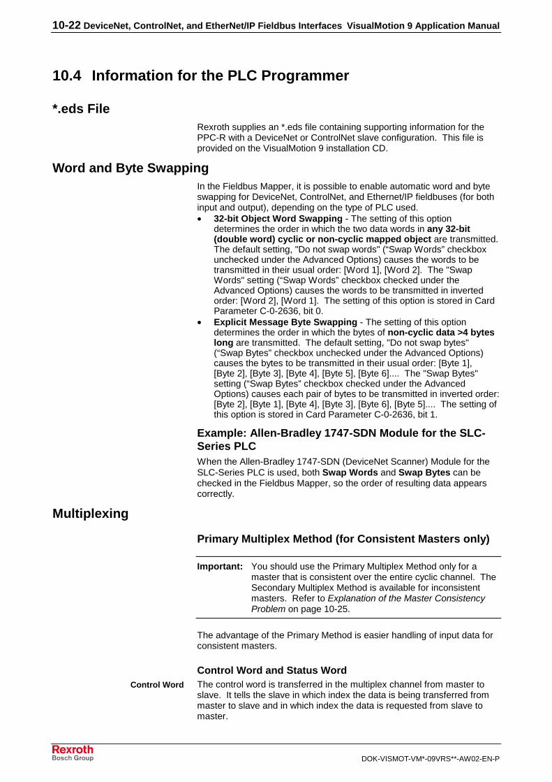
10-22 DeviceNet, ControlNet, and EtherNet/IP Fieldbus Interfaces VisualMotion 9 Application Manual
DOK-VISMOT-VM*-09VRS**-AW02-EN-P
10.4 Information for the PLC Programmer
*.eds FileRexroth supplies an *.eds file containing supporting information for thePPC-R with a DeviceNet or ControlNet slave configuration. This file isprovided on the VisualMotion 9 installation CD.
Word and Byte SwappingIn the Fieldbus Mapper, it is possible to enable automatic word and byteswapping for DeviceNet, ControlNet, and Ethernet/IP fieldbuses (for bothinput and output), depending on the type of PLC used.• 32-bit Object Word Swapping - The setting of this option
determines the order in which the two data words in any 32-bit(double word) cyclic or non-cyclic mapped object are transmitted.The default setting, "Do not swap words" (“Swap Words” checkboxunchecked under the Advanced Options) causes the words to betransmitted in their usual order: [Word 1], [Word 2]. The "SwapWords" setting (“Swap Words” checkbox checked under theAdvanced Options) causes the words to be transmitted in invertedorder: [Word 2], [Word 1]. The setting of this option is stored in CardParameter C-0-2636, bit 0.
• Explicit Message Byte Swapping - The setting of this optiondetermines the order in which the bytes of non-cyclic data >4 byteslong are transmitted. The default setting, "Do not swap bytes"(“Swap Bytes” checkbox unchecked under the Advanced Options)causes the bytes to be transmitted in their usual order: [Byte 1],[Byte 2], [Byte 3], [Byte 4], [Byte 5], [Byte 6].... The "Swap Bytes"setting (“Swap Bytes” checkbox checked under the AdvancedOptions) causes each pair of bytes to be transmitted in inverted order:[Byte 2], [Byte 1], [Byte 4], [Byte 3], [Byte 6], [Byte 5].... The setting ofthis option is stored in Card Parameter C-0-2636, bit 1.
Example: Allen-Bradley 1747-SDN Module for the SLC-Series PLCWhen the Allen-Bradley 1747-SDN (DeviceNet Scanner) Module for theSLC-Series PLC is used, both Swap Words and Swap Bytes can bechecked in the Fieldbus Mapper, so the order of resulting data appearscorrectly.
Multiplexing
Primary Multiplex Method (for Consistent Masters only)
Important: You should use the Primary Multiplex Method only for amaster that is consistent over the entire cyclic channel. TheSecondary Multiplex Method is available for inconsistentmasters. Refer to Explanation of the Master ConsistencyProblem on page 10-25.
The advantage of the Primary Method is easier handling of input data forconsistent masters.
Control Word and Status WordThe control word is transferred in the multiplex channel from master toslave. It tells the slave in which index the data is being transferred frommaster to slave and in which index the data is requested from slave tomaster.
Control Word

VisualMotion 9 Application Manual DeviceNet, ControlNet, and EtherNet/IP Fieldbus Interfaces 10-23
DOK-VISMOT-VM*-09VRS**-AW02-EN-P
15 14 13 12 11 10 9 8 7 6 5 4 3 2 1 0
Multiplex Output ControlIndex (index_out_c)
(defines the output index commandfor multiplexing)
Write RequestToggle Bit
(WR)(initiates the write
command once eachtime it is toggled)
Multiplex Input ControlIndex (index_in_c)
(defines the input index command formultiplexing)
Multiplex Input ControlByte
Multiplex Output ControlByte
Fig. 10-19: Control Word Definition, Primary Multiplex Method
• Index_out_c: tells the slave in which index the data are transferredfrom master to slave (out = master -> slave, _c = element of controlword).
• Index_in_c: tells the slave in which index the data is requested fromslave to master (in = slave -> master, _c = element of control word).
• WR (Write Request): handshake bit (refer to meaning of WR andWA).
Note: Input data via the Multiplex Channel is continually beingupdated.
The status word is transferred in the multiplex channel from slave tomaster. It acknowledges the written index and the requested index.
15 14 13 12 11 10 9 8 7 6 5 4 3 2 1 0
Multiplex Input StatusIndex (index_in_s)
(confirms that the input indexresponse location matches that of the
command location)
Multiplex Output StatusIndex (index_out_s)
(confirms that the output indexresponse location matches that of the
command location)
Write RequestAcknowledge
Bit (WA)(checks that the
write data has beenread once each
time it is toggled)
Multiplex Input Status Byte Multiplex Output StatusByte
Fig. 10-20: Status Word Definition, Primary Multiplex Method
• Index_out_s: acknowledges index written by the master (out = master-> slave, _s = element of status word).
• Index_in_s: tells the master which index is transferred from slave tomaster in the actual process data cycle (in = slave -> master, _s =element of status word).
• WA (Write Acknowledge): Handshake bit (refer to meaning of WRand WA).
Handshake Bits WR and WAWR and WA are handshake bits that allow the controlled writing of datavia the multiplex channel. WR and WA control the data transfer forwriting data_out (data send from master to slave).
Status Word

10-24 DeviceNet, ControlNet, and EtherNet/IP Fieldbus Interfaces VisualMotion 9 Application Manual
DOK-VISMOT-VM*-09VRS**-AW02-EN-P
WR == WA:
• tells the master that the slave has received the last multiplex data_out.The master can now send new data_out.
• tells the slave to do nothing, because the master has not yet put newconsistent data_out on the bus.
WR! = WA:
• tells the slave to do something, because the master has now putconsistent new data_out on bus.
• tells the master to do nothing, because the slave has not yet receivedthe latest multiplex data_out.
Master Communications (Primary Multiplex Method)
Begin
Control word =0
Index_in_c ==Index_in_s ?
Read Index_in_s,Read Data_in,
Write Index_in_c
WR == WA ? Write Data_out,Write Index_out_c,
Toggle RT (Set WR = ~WA)
Read Data_in
Write Data_out
Yes
No
Yes
No
Fig. 10-21: Primary Multiplex Method, Master Communications
Programming ExampleTo aid in implementing the multiplex function in a PLC program, thefollowing flow chart shows two ways of reading and writing data. Readingand writing can be executed separately, which allows the input data to beupdated about 30% faster. The “Read Data” example would be placed atthe beginning of a PLC program the “Write Data” example at the end.
Combined reading and writing makes the PLC program simpler,especially when using the same index for both transfer actions.

VisualMotion 9 Application Manual DeviceNet, ControlNet, and EtherNet/IP Fieldbus Interfaces 10-25
DOK-VISMOT-VM*-09VRS**-AW02-EN-P
���������
���
�0
��#!��2�"'!�2���A
��#!��0'!"'!���!�! �+')!#")�A�& �!�#���=�>
��#!��0'!"'!�2���A
� $$)����#!���B'��!�.#!
�0
���
��������
#��
��������������
���������! ��2�"'!���!��*� 6
+C")�A�& �!�#���=�>
��!�/
:&�&;<)�
����/:&
�&;<)�
��#!��0'!"'!���!�! �+')!#")�A�& �!�#���=�>
+C")�A2�"'!
& �!� )�.;!�1
+C")�A�2�"'!�!�!'�.;!�D
+C")�A& �!� )� ��
+C")�A�!�!'�� ��D
���������! ��2�"'!���!��*� 6
+C")�A�& �!�#���=�>
+C")�A0'!"'!
& �!� )�.;!�1
+C")�A�0'!"'!�!�!'�.;!�D
��#!��2�"'!����0'!"'!�2���A��
� $$)����#!���B'��!�.#!
�0
1
Multiplexing flow chart.FH7
Fig. 10-22: Flow Chart of Multiplex Programming Examples (Primary Method)
Secondary Multiplex Method (for Inconsistent Masters)
Explanation of the Master Consistency ProblemThe PPC-R fieldbus slave interfaces can guarantee consistency,however, some fieldbus masters can only guarantee byte, word or doubleword consistency. If the master is only word-consistent, it is possible thatthe master cannot transfer the data and the control word of one multiplexindex consistently from the PLC to the fieldbus. Therefore, it is necessaryto have a second multiplex method where both input data and output datarequire the handshake bits to update via the fieldbus.
Note: The meanings of the control and status words are the same asfor the Primary Multiplex Method. The only difference is thattoggle bits RR and RA are used in the Secondary Method.
Fig. 10-23 and Fig. 10-24 below illustrate the control and status worddefinitions for the Secondary Multiplex Method.
15 14 13 12 11 10 9 8 7 6 5 4 3 2 1 0
Multiplex Control Input Index(defines the input index command for
multiplexing)
Multiplex Output Control Index(index_out_c)
(defines the output index command formultiplexing)
Write RequestToggle Bit (WR)
(initiates the writecommand once each
time it is toggled)
RRsee definition
under “HandshakeBits WR / WA and
RR / RA”(Secondary
Method only)
Multiplex Input Control Index(index_in_c)
(defines the input index command formultiplexing)
Multiplex Input Control Byte Multiplex Output Control Byte
Fig. 10-23: Control Word Definition, Secondary Multiplex Method

10-26 DeviceNet, ControlNet, and EtherNet/IP Fieldbus Interfaces VisualMotion 9 Application Manual
DOK-VISMOT-VM*-09VRS**-AW02-EN-P
15 14 13 12 11 10 9 8 7 6 5 4 3 2 1 0
Multiplex Input Status Index(index_in_s)
(confirms that the input index responselocation matches that of the command
location)
RAsee definition
under “HandshakeBits WR / WA and
RR / RA”(Secondary
Method only)
Multiplex Output Status Index(index_out_s)
(confirms that the output index responselocation matches that of the command
location)
Write RequestAcknowledge Bit
(WA)(checks that the writedata has been readonce each time it is
toggled)
Multiplex Input Status Byte Multiplex Output Status Byte
Fig. 10-24: Status Word Definition, Secondary Multiplex Method
The Secondary Multiplex Method has the following features:
• You can transfer a different index from master to slave as from slaveto master.
• The handshake bits for both reading and writing of this multiplexchannel make the multiplexing possible on inconsistent systems(masters).
Handshake Bits RR and RARR (Read Request) and RA (Read Acknowledge) are handshake bits thatallow a controlled data transfer and use of the multiplex channel oninconsistent masters. RR and RA control the data transfer for readingdata_in (data send from slave to master).
RR == RA:
• tells the master that the slave has sent the requested data_in. Themaster can now read the data_in and request new data_in.
• tells the slave to do nothing, because the master has not yet put newconsistent data on the bus.
RR != RA:
• tells the slave to put new data_in on the bus, because the masterrequests new data_in.
• tells the master to do nothing, because the slave has not yet put thelatest requested multiplex data_in on the bus.

VisualMotion 9 Application Manual DeviceNet, ControlNet, and EtherNet/IP Fieldbus Interfaces 10-27
DOK-VISMOT-VM*-09VRS**-AW02-EN-P
Master Communications (Secondary Multiplex Method)
Begin
Control Word =0
RR==RA ? Read Index_in_s,Read Data_in,
Write Index_in_cYes
No
WR == WA ?Yes
No
Write Data_out,Write Index_out_c,
Toggle WRT (Set WR = ~WA)
Read Data_in
Write Data_out
Toggle RRT (Set RR = ~RA)
*1how to become consistent could be different from master to master
Fig. 10-25: Secondary Multiplex Method, Master Communications
For some masters, it could be enough to first write data and then thecontrol word. For other masters, you may have to implement a delay time(this time could be different from master to master) before writing WR =~WA.
Non-Cyclic Data (Explicit Messaging)The following methods for transferring data are available via DeviceNet,ControlNet, and Ethernet/IP Explicit Messaging:
• Mapped Data
• Data Exchange Objects
Mapped DataMapped data is the most powerful feature of the PPC-R non-cyclicfieldbus interface. Through mapped data, the user has access to virtuallyevery PPC-R parameter over the fieldbus. It is easy to implement fromthe PLC side and requires no setup on the PPC-R side.
To access a VisualMotion data type over the fieldbus, it has to bespecified by an address that consists of a Class, Instance and Attribute.The Class, Instance and Attribute for each data type can be calculated bya formula (refer to Example Lookup Tables for Mapped Data on page 10-40).

10-28 DeviceNet, ControlNet, and EtherNet/IP Fieldbus Interfaces VisualMotion 9 Application Manual
DOK-VISMOT-VM*-09VRS**-AW02-EN-P
&)����5�2��!��
&)����5�2��!��
&)����5�2��!��
&)����5�2��!��
�?/���6�!���
/?/���6�!���
&)����5�2��!��
&)����5�2��!���A#�?
/���6�!���
9#�)�4'���!�
�#�'�)+ !# ���!�
�!!�#4'!�
��#(��,&)���5�2��!��<�
�A#��,
�?�
�?����
/?����
/?�
�?�
�?����
object_mapping_DN.FH7
Fig. 10-26: Mapped Data
Mapped data can be used with the following parameters and values:
• S-Parameters (SERCOS Drive S-Parameters)
• P-Parameters (SERCOS Drive P-Parameters)
• A-Parameters (PPC Axis Parameters)
• C-Parameters (PPC C System parameters)
• T-Parameters (PPC Task parameters)
size and
formatdepend on
parameter *,1
PF-Values (PPC Program Float data, 32 bit – 2 words, IEEE format) *,2
GI-Values (PPC Global Integer data, 32 bit – 2 words) *,2
GF-Values (PPC Global Float data, 32 bit – 2 words, IEEE format) *,2
PI-Values (PPC Program Integer data, 32 bit – 2 words) *,2
Reg.-Values (PPC Register data, 16 bit – 1 word) *,3
Data Exchange Objects (0x5E70 – 0x5E73) (embedded ASCII Protocol)
*You may notice that parameters accessed via the non-cyclic (Parameter) channel are not always the samesize as reported from the attribute field. This is so that the data sizes correspond with the way the different datatypes are handled in the cyclic channel (Registers are always set to 16-bit size and Parameters are cast to 32-bit size, even if they actually use less space).
1. When writing mapped data to a VisualMotion Parameter, you must send the size datacorresponding to that of the attribute field within the parameter.
a.) For 32-bit parameters, you must send a data size of 32 bits (otherwise, VM error #07 isreturned).
b.) For 16-bit parameters, you must send a data of size 16-bits. If, for this case, you send data ofsize 32 bits, one of the following occurs:
i.) For parameters of type 16-bit unsigned, only the Low word is stored, and the High word isignored.
ii.) For parameters of type 16-bit signed, bits 0-14 of the low word along with the sign bit #31are used, and the remaining bits are ignored.
c.) For String Parameters (e.g. S-0-0142), you must send the size of the string to write.

VisualMotion 9 Application Manual DeviceNet, ControlNet, and EtherNet/IP Fieldbus Interfaces 10-29
DOK-VISMOT-VM*-09VRS**-AW02-EN-P
d.) All other Parameter Types (list parameters, command parameters, etc), are not supported formapped data.
When reading mapped data from a VisualMotion Parameter, there are 3 possible cases of sizesreturned:
a.) If the parameter type is a string, you receive the number of bytes corresponding to the length ofthe string.
b.) If the parameter is 32-bit or less, you receive a cast 32-bit value for this parameter. This impliesthat 16-bit parameters are returned as cast in to 32-bit values.
c.) All other parameter types (e.g. list parameters, command parameters, etc.), are not supportedfor mapped data.
2. When writing mapped data to a VisualMotion Program Float, Program Integer, Global Float, orGlobal Integer, the data size must be 32-bits (2 words). Any other size returns a VM error #07(Invalid Data Format).
When reading mapped data from a VisualMotion Program Float, Program Integer, Global Float, orGlobal Integer, the data size returned is always 32-bit (2 words).
3. When writing mapped data to a VisualMotion Register, the data must be 16-bits (1 word). Any othersize returns a VM error #07 (Invalid Data Format).
When reading mapped data from a VisualMotion Register, the data size returned is always 16-bit (1 word).
Selecting Mapped DataTo access a data type over the fieldbus, it has to be specified by anaddress that consists of a Class, Instance and Attribute. Class, Instanceand Attribute for each data type can be calculated by a formula (refer toExplicit Messaging Error Codes (Low-Byte) for 0x1F
Error No.(Hex)
Error Description
0xF3 Invalid Attribute – Occurs when an attempt to access an incorrect orundefined location in the mapped data area.
0xF2 Invalid Class and Instance – Occurs when attempting to access anincorrect or undefined location in the mapped data area.
0xF1 Not used
0xF0 ASCII Format Error – occurs when attempting to communicate viathe Data Exchange object where VisualMotion ASCII protocol issent. This error also occurs if the initial characters are incorrect(such as the absence of the “>” start character).
Table 10-12: Parameter Channel Error Codes (Low-Byte)
Accessing Mapped Data on page 10-38).
Transmission Sequence for Mapped Data
Note: For mapped data, only one transmission (and one response)is required, to send a read or write message to and receive aresponse from the PPC-R.

10-30 DeviceNet, ControlNet, and EtherNet/IP Fieldbus Interfaces VisualMotion 9 Application Manual
DOK-VISMOT-VM*-09VRS**-AW02-EN-P
HeaderRaw Data
key components:• service code: Read = 0x0E
Write = 0x10• mapped data (under VisualMotion
Mapped Data at the end of this section).This is the destination of the data field.Selection of the Class, Instance andAttribute depends on the requiredVisualMotion.
• Data field size (in bytes)minimum = 6 bytes for Class, Instance,Attribute
key components:• raw data to be transmitted
(write message only; unused forread message)
Data Field:
Fieldbus Message
Important: The format of the Fieldbus message header and the methodof implementation are dependent on the Fieldbus type andthe master (PLC) being used. Refer to your Fieldbusmaster/PLC documentation for proper transport andformatting of the message header.
Non-Cyclic Mapped Data Write
No
FB Write Command toappropriate Class,
Instance and AttributeRaw data
FB ResponseReceived?
Yes
FB ResponseOK?
No
Yes
Message Steps Process Comments
1. Write request from themaster with raw data.
2. Acknowledge fieldbusresponse from slave.
The data field for the writerequest contains the value to bestored in the VisualMotion data.
The response message containsonly a confirmation that thefieldbus message was sentproperly. Therefore, the size ofthe data field will be 0.
Done
Diagnoseerror
Fig. 10-27: Non-Cyclic Mapped Data Write Process
Write the value -27.43 to Program Float 16 (This is a 32-bit data type,which is mapped to Class 165, Instance 1, and Attribute 16. The Class,Instance and Attribute can be calculated using the formulas under ExplicitMessaging Error Codes (Low-Byte) for 0x1F
Example:

VisualMotion 9 Application Manual DeviceNet, ControlNet, and EtherNet/IP Fieldbus Interfaces 10-31
DOK-VISMOT-VM*-09VRS**-AW02-EN-P
Error No.(Hex)
Error Description
0xF3 Invalid Attribute – Occurs when an attempt to access an incorrect orundefined location in the mapped data area.
0xF2 Invalid Class and Instance – Occurs when attempting to access anincorrect or undefined location in the mapped data area.
0xF1 Not used
0xF0 ASCII Format Error – occurs when attempting to communicate viathe Data Exchange object where VisualMotion ASCII protocol issent. This error also occurs if the initial characters are incorrect(such as the absence of the “>” start character).
Table 10-12: Parameter Channel Error Codes (Low-Byte)
Accessing Mapped Data at the end of this chapter.)
1. Write request from the master with raw data.
Header:VisualMotion raw data
Data Field:
contains:• Write service code = (0x10)• object number (Class 165, Instance 1,
Attribute 16)• data field size (bytes—in this case: 4) +
(6 bytes for Class, Inst, Att) = 10 bytes
contains data (here, shown indecimal format):-27.43
Write command
2. After the write request from the master, the PPC-R sends a responsemessage.
Header:
contains:• “Write” message o.k. is denoted by a
Response service code of (0x90)• data field size = 0 bytes
Response messageNo data field
3. If the message response (code in message header) shows o.k., thetransaction is complete.

10-32 DeviceNet, ControlNet, and EtherNet/IP Fieldbus Interfaces VisualMotion 9 Application Manual
DOK-VISMOT-VM*-09VRS**-AW02-EN-P
Non-Cyclic Mapped Data Read
No
FB Read Command toappropriate Class,
Instance and Attribute
FB ResponseReceived?
Yes
FB ResponseOK?
No
Yes
Message Steps Process Comments
1. Read request from themaster with no data field.
2. Acknowledge fieldbusresponse from slave.
The data field for the responsecontains the value requestedfrom the slave (PPC-R).
The request message containsonly the fieldbus read commandand the Class, Instance andAttribute to be read.
VisualMotion rawdata is available
for use by master.
3. Master uses data fromfieldbus response.
Diagnoseerror
Fig. 10-28: Non-Cyclic Mapped Data Read Process
Read the value contained in Program Integer 8. (This is a 32-bit datatype, which is mapped to Class 165, Instance 21, and Attribute 8. TheClass, Instance and Attribute can be calculated using the formulas underExplicit Messaging Error Codes (Low-Byte) for 0x1F
Error No.(Hex)
Error Description
0xF3 Invalid Attribute – Occurs when an attempt to access an incorrect orundefined location in the mapped data area.
0xF2 Invalid Class and Instance – Occurs when attempting to access anincorrect or undefined location in the mapped data area.
0xF1 Not used
0xF0 ASCII Format Error – occurs when attempting to communicate viathe Data Exchange object where VisualMotion ASCII protocol issent. This error also occurs if the initial characters are incorrect(such as the absence of the “>” start character).
Table 10-12: Parameter Channel Error Codes (Low-Byte)
Accessing Mapped Data at the end of this chapter.)
1. Read request from the master.
Header:
contains:• Read service code = (0x0E)• Class 165, Instance 21, Attribute 8• data field size = 6 bytes for Class, Inst, Att
Read commandNo data field
2. After the read request from the master, the PPC-R sends a responsemessage.
Example:

VisualMotion 9 Application Manual DeviceNet, ControlNet, and EtherNet/IP Fieldbus Interfaces 10-33
DOK-VISMOT-VM*-09VRS**-AW02-EN-P
Header:VisualMotion raw data
Data Field:
contains:• “Read” message o.k. is denoted by a
Response service code of (0x8E)• data field size = 4 bytes
contains data (here, shown indecimal format):12345
Response message
If the message response (code in message header) shows o.k., therequested value is attached to the message in the data field. This valueis now available for use by the master (PLC).
Data Exchange ObjectsThe four data exchange objects Class 100, Instance 1-4, Attribute 100represent fixed data "containers" of varying lengths that transfer theVisualMotion ASCII Protocol to the PPC-R. These objects serve as an open-ended possibility to access any VisualMotion data (including cams, diagnostictext, etc.), but more work is required in the master to perform a transmissionof this type. Both the VisualMotion ASCII message and the fieldbus transfermessage must be formulated.
Table 10-10 below lists the available data exchange objects and their sizes.
Data Exchange Object Data Length (in bytes)
Class 100, Instance 1, Attribute 100 16
Class 100, Instance 2, Attribute 100 32
Class 100, Instance 3, Attribute 100 64
Class 100, Instance 4, Attribute 100 128
Table 10-10: Length of the Data Exchange Objects
Selecting a Data Exchange ObjectDepending on the length of a VisualMotion ASCII message, any of thesedata exchange objects can be selected.
Note: The entire data length of the data exchange object mustalways be transmitted even if the VisualMotion ASCII messageis shorter.For example, if you want to transmit an ASCII message of 42bytes, you must use Class 100, Instance 3. To avoid aresponse error from the Fieldbus slave, you must append 22"Null" characters to the end of the ASCII message to completea data size of 64 bytes.
Note: The checksum for the VisualMotion ASCII protocol is NOTused with the data exchange object. If the checksum is sentas part of the string, it will be ignored, and no checksum will besent in the VisualMotion ASCII response messages. Toensure data integrity, the Fieldbus protocols support a low-level checksum.
Transmission Sequence via a Data Exchange Object
Note: For the data exchange object, two transmissions (and tworesponses) are required, to send the read or write message toand then receive the response message from the PPC-R.

10-34 DeviceNet, ControlNet, and EtherNet/IP Fieldbus Interfaces VisualMotion 9 Application Manual
DOK-VISMOT-VM*-09VRS**-AW02-EN-P
HeaderVisualMotion ASCII Protocol
key components:• service code: Read = 0x0E
Write = 0x10• data exchange object (Class 100,
Instance 1-4, Attribute 100). This is thedestination of the data field. Objectselection depends on required data fieldsize.
• data field size (in bytes)minimum = 6 bytes for Class, Instance,Attribute
key components:• VisualMotion command
(read or write data)
• ASCII data contained in the selecteddata exchange object
• The <CR> (0x0D) and <LF> (0x0A)characters must be applied to theASCII string
• A checksum is not used in this case.(Fieldbus has a checksum)
Note: Refer to the VisualMotion 6Reference Manual for an explanation of theVisualMotion ASCII Protocol.
Data Field:
Fieldbus Message
Fig. 10-29: Format of a Non-Cyclic Fieldbus Message using a Data ExchangeObject
Important: The format of the fieldbus message header is dependent onthe type of master (PLC) being used. Refer to your PLCmanufacturer's manual for specific information on this topic.
The following sequence describes the communication between theFieldbus master (PLC) and the Fieldbus slave (PPC-R):

VisualMotion 9 Application Manual DeviceNet, ControlNet, and EtherNet/IP Fieldbus Interfaces 10-35
DOK-VISMOT-VM*-09VRS**-AW02-EN-P
VM ASCII protocolcommand text
(read or write data)
FB ResponseReceived?
No
Yes
FB ResponseOK?
No
Yes
No data
FB ResponseReceived?
No
Yes
FB ResponseOK?
No
Yes
VM ASCII protocolresponse text
(write or transmit data)
Message Steps Process Comments
4. Receive fieldbus responsefrom slave.
FB Read Command
FB Write Command1. Write request from themaster with VisualMotionASCII Protocol.
2. Acknowledge fieldbusresponse from slave.
3. Read request from themaster to get VisualMotionASCII response.
The data field for the writerequest can contain aVisualMotion read or writeprotocol.
The response message containsonly a confirmation that thefieldbus message was sentproperly. Therefore, the size ofthe data field will be 0.
The read request messagecontains only header information(the data field is 0). You mustanticipate the approximate sizeof the data field (VisualMotionASCII response message) inorder to select the appropriatedata exchange object. If theselected object is too short, thedata will be truncated.
The response message willcontain the VisualMotion ASCIIresponse to the VisualMotionASCII command text in Step 1.
Diagnoseerror
Diagnoseerror
Fig. 10-30: Non-Cyclic (Explicit Messaging) VisualMotion ASCII CommunicationProcess
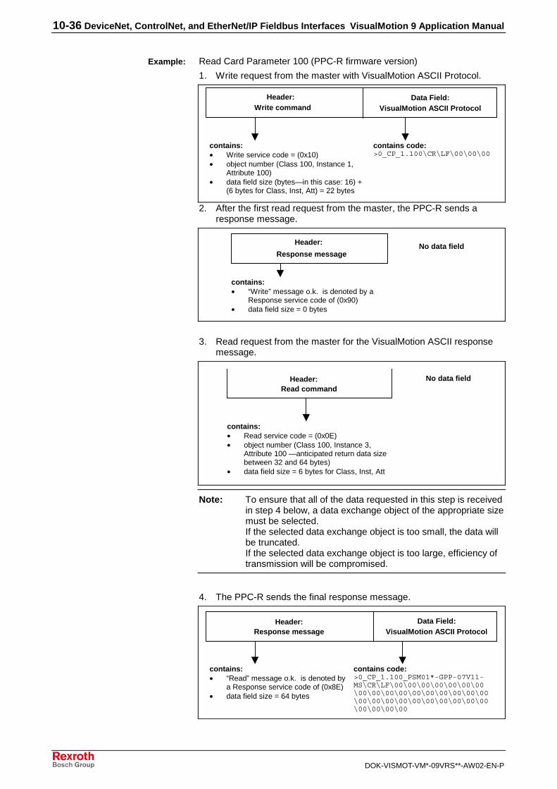
10-36 DeviceNet, ControlNet, and EtherNet/IP Fieldbus Interfaces VisualMotion 9 Application Manual
DOK-VISMOT-VM*-09VRS**-AW02-EN-P
Read Card Parameter 100 (PPC-R firmware version)
1. Write request from the master with VisualMotion ASCII Protocol.
Header:
VisualMotion ASCII ProtocolData Field:
contains:• Write service code = (0x10)• object number (Class 100, Instance 1,
Attribute 100)• data field size (bytes—in this case: 16) +
(6 bytes for Class, Inst, Att) = 22 bytes
contains code:>0_CP_1.100\CR\LF\00\00\00
Write command
2. After the first read request from the master, the PPC-R sends aresponse message.
Header:
contains:• “Write” message o.k. is denoted by a
Response service code of (0x90)• data field size = 0 bytes
Response messageNo data field
3. Read request from the master for the VisualMotion ASCII responsemessage.
Header:
contains:• Read service code = (0x0E)• object number (Class 100, Instance 3,
Attribute 100 —anticipated return data sizebetween 32 and 64 bytes)
• data field size = 6 bytes for Class, Inst, Att
Read commandNo data field
Note: To ensure that all of the data requested in this step is receivedin step 4 below, a data exchange object of the appropriate sizemust be selected.If the selected data exchange object is too small, the data willbe truncated.If the selected data exchange object is too large, efficiency oftransmission will be compromised.
4. The PPC-R sends the final response message.
Header:VisualMotion ASCII Protocol
Data Field:
contains:• “Read” message o.k. is denoted by
a Response service code of (0x8E)• data field size = 64 bytes
contains code:>0_CP_1.100_PSM01*-GPP-07V11-MS\CR\LF\00\00\00\00\00\00\00\00\00\00\00\00\00\00\00\00\00\00\00\00\00\00\00\00\00\00\00\00\00\00\00
Response message
Example:
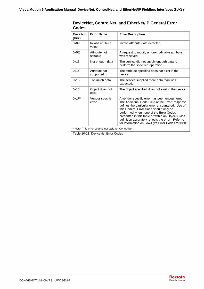
VisualMotion 9 Application Manual DeviceNet, ControlNet, and EtherNet/IP Fieldbus Interfaces 10-37
DOK-VISMOT-VM*-09VRS**-AW02-EN-P
DeviceNet, ControlNet, and EtherNet/IP General ErrorCodes Error No.(Hex)
Error Name Error Description
0x09 Invalid attributevalue
Invalid attribute data detected.
0x0E Attribute notsettable
A request to modify a non-modifiable attributewas received.
0x13 Not enough data The service did not supply enough data toperform the specified operation.
0x14 Attribute notsupported
The attribute specified does not exist in thedevice.
0x15 Too much data The service supplied more data than wasexpected.
0x16 Object does notexist
The object specified does not exist in the device.
0x1F* Vendor-specificerror
A vendor-specific error has been encountered.The Additional Code Field of the Error Responsedefines the particular error encountered. Use ofthis General Error Code should only beperformed when none of the Error Codespresented in this table or within an Object Classdefinition accurately reflects the error. Refer tofor information on Low-Byte Error Codes for 0x1F
* Note: This error code is not valid for ControlNet
Table 10-11: DeviceNet Error Codes

10-38 DeviceNet, ControlNet, and EtherNet/IP Fieldbus Interfaces VisualMotion 9 Application Manual
DOK-VISMOT-VM*-09VRS**-AW02-EN-P
Explicit Messaging Error Codes (Low-Byte) for 0x1F
Error No.(Hex)
Error Description
0xF3 Invalid Attribute – Occurs when an attempt to access an incorrect orundefined location in the mapped data area.
0xF2 Invalid Class and Instance – Occurs when attempting to access anincorrect or undefined location in the mapped data area.
0xF1 Not used
0xF0 ASCII Format Error – occurs when attempting to communicate viathe Data Exchange object where VisualMotion ASCII protocol issent. This error also occurs if the initial characters are incorrect(such as the absence of the “>” start character).
Table 10-12: Parameter Channel Error Codes (Low-Byte)
Accessing Mapped DataRexroth has pre-configured a number of VisualMotion data types toDeviceNet, ControlNet, or EtherNet/IP Classes, Instances and Attributes.We call this concept-mapped data. These data types can be accessedvia DeviceNet/ControlNet/EtherNet/IP Explicit Messaging. The Class,Instance and Attribute for each of these data types can be calculatedusing the formulas in Table 10-13 below.

VisualMotion 9 Application Manual DeviceNet, ControlNet, and EtherNet/IP Fieldbus Interfaces 10-39
DOK-VISMOT-VM*-09VRS**-AW02-EN-P
Class,Instance Attribute Formula
Class 166Instance 137
0 Note: for backwards compatibility, also listed as
Data Exchange Object ---- ---- Class 100, Instance 1 - 4, Attribute 100
Class 166Instance 134
0
Class 166,Instance 133
255
<FREE> ---- ----
(349 objects available) Class 165Instance 41
1
Class 165Instance 40
255 Class = 165
Program Integers ---- ---- Instance = 21 + [(Program Integer - 1) \ 255]
(Int 1 – Int 5100) Class 165Instance 21
1 Attribute = Program Integer - [(Instance - 21) * 255)]
Class 165Instance 20
255 Class = 165
Program Floats ---- ---- Instance = 1 + [(Program Float - 1) \ 255]
(Float 1 – Float 5100) Class 165,Instance 1
1 Attribute = Program Float - [(Instance - 1) * 255)]
Class 164,Instance 255
255
<FREE> ---- ----
(235 objects available) Class 164,Instance 21
1
Class 164,Instance 20
255 Class = 164
Global Integers ---- ---- Instance = 11 + [(Global Integer - 1) \ 255]
(GInt 1 – GInt 2550*) Class 164,Instance 11
1 Attribute = Global Integer - [(Instance - 11) * 255)]
Class 164,Instance 10
255 Class = 164
Global Floats ---- ---- Instance = 1 + [(Global Float - 1) \ 255]
(GFloat 1 – Gfloat 2550*) Class 164,Instance 1
1 Attribute = Global Float - [(Instance - 1) * 255)]
Class 163,Instance 255
255
<FREE> ---- ----
(245 objects available) Class 163,Instance 11
1
Class 163,Instance 10
255 Class = 163
Registers ---- ---- Instance = 1 + [(Register - 1) \ 255]
(Reg. 1 – Reg. 2550**) Class 163,Instance 1
1 Attribute = Register - [(Instance - 1) * 255)]
Class 162,Instance 255
4 Class = 159 + [(T-Parameter - 1) \ 255]
T-Parameters ---- ---- Instance = T-Parameter - [(Class - 159) * 255]
(T-0-0001 – T-0-1020) Class 159,Instance 1
1 Attribute = Task Number
Class 158,Instance 255
255
<FREE> ---- ----
(GFloat 1 – Gfloat 2550) Class 158,Instance 14
1
Class 158,Instance 13
1 Class = 144 + [(C-Parameter - 1) \ 255]
C-Parameters ---- ---- Instance = C-Parameter - [(Class - 144) * 255]

10-40 DeviceNet, ControlNet, and EtherNet/IP Fieldbus Interfaces VisualMotion 9 Application Manual
DOK-VISMOT-VM*-09VRS**-AW02-EN-P
Class,Instance Attribute Formula
(C-0-0001 - C-0-3583) Class 144,Instance 1
1 Attribute = 1 (data)
Class 143,Instance 7
99 Class = 135 + [(A-Parameter - 1) \ 255]
A-Parameters ---- ---- Instance = A-Parameter - [(Class - 135) * 255]
(A-0-0001 - A-0-2047) Class 135,Instance 1
1 Attribute = Axis Number
Class 134,Instance 15
99 Class = 118 + [(P-Parameter - 1) \ 255]
P-Parameters ---- ---- Instance = P-Parameter - [(Class - 118) * 255]
(P-0-0001 - P-0-4095) Class 118,Instance 1
1 Attribute = Drive Number
Class 117,Instance 15
99 Class = 101 + [(S-Parameter - 1) \ 255]
S-Parameters ---- ---- Instance = S-Parameter - [(Class - 101) * 255]
(S-0-0001 - S-0-4095) Class 101,Instance 1
1 Attribute = Drive Number
* current limitation: C-0-0080/C-0-0081 - Maximum number global integers/floats.**current limitation: first 1024 registers.
Table 10-13: Formulas for Determining Mapped Objects
Example Lookup Tables for Mapped DataThe following is an example lookup table for C-Parameters, when usingmapped objects.
Example Look-up Chart for: C-Parameters CP 0.Y ==> CP = Card Parameter
Y = Parameter Number
Class 144 Class 144 Class 144 …………… Class 144 Class 145 …………… Class 158 Class 158
Instance 1 Instance 2 Instance 3 …………… Instance 255 Instance 1 …………… Instance 12 Instance 13
Attribute ID 1 CP 0.1 CP 0.2 CP 0.3 CP 0.255 CP 0.256 CP 0.3582 CP 0.3583
Table 10-14: C-Parameters Lookup Table for Mapped Data Types
The following is an example lookup table for A-Parameters, when usingmapped objects. The same formula also applies to SERCOS (S) andTask (T) Parameters.
Card (C) Parameters
Axis(A) Parameters

VisualMotion 9 Application Manual DeviceNet, ControlNet, and EtherNet/IP Fieldbus Interfaces 10-41
DOK-VISMOT-VM*-09VRS**-AW02-EN-P
Example Look-up Chart for: A-Parameters AP X.Y ==> AP = Axis Parameter
X = Axis Number
Y = Parameter Number
Class 135 Class 135 Class 135 …………… Class 135 Class 136 …………… Class 143 Class 143
Instance 1 Instance 2 Instance 3 …………… Instance 255 Instance 1 …………… Instance 6 Instance 7
1 AP 1.1 AP 1.2 AP 1.3 AP 1.255 AP 1.256 AP 1.2046 AP 1.2047
Attribute ID 2 AP 2.1 AP 2.2 AP 2.3 AP 2.255 AP 2.256 AP 2.2046 AP 2.2047
3 AP 3.1 AP 3.2 AP 3.3 AP 3.255 AP 3.256 AP 3.2046 AP 3.2047
: : : : : : : : : :
: : : : : : : : : :
40 AP 40.1 AP 40.2 AP 40.3 AP 40.255 AP 40.256 AP 40.2046 AP 40.2047
Table 10-15: A-Parameters Lookup Table for Mapped Data Types
The following is an example lookup table for P-Parameters, when usingmapped objects.
Example Look-up Chart for: P-Parameters PP X.Y ==> PP = SERCOS P-Parameter (set 0 only)
X = Drive Number
Y = Parameter Number
Class 118 Class 118 Class 118 …………… Class 118 Class 119 …………… Class 134 Class 134
Instance 1 Instance 2 Instance 3 …………… Instance 255 Instance 1 …………… Instance 14 Instance 15
1 PP 1.1 PP 1.2 PP 1.3 PP 1.255 PP 1.256 PP 1.4094 PP 1.4095
Attribute ID 2 PP 2.1 PP 2.2 PP 2.3 PP 2.255 PP 2.256 PP 2.4094 PP 2.4095
3 PP 3.1 PP 3.2 PP 3.3 PP 3.255 PP 3.256 PP 3.4094 PP 3.4095
: : : : : : : : : :
: : : : : : : : : :
40 PP 40.1 PP 40.2 PP 40.3 PP 40.255 PP 40.256 PP 40.4094 PP 40.4095
Table 10-16: P-Parameters Lookup Table for Mapped Data Types
The following is an example lookup table for Integers, when usingmapped objects. The same formula also applies to Floats, GlobalIntegers, Global Floats and Registers.
Product-Specific (P) Parameters
Integers

10-42 DeviceNet, ControlNet, and EtherNet/IP Fieldbus Interfaces VisualMotion 9 Application Manual
DOK-VISMOT-VM*-09VRS**-AW02-EN-P
Example Look-up Chart for: VM Program Integers PI 0.Y ==> PI = Program Integer
Y = Program Integer Number
Class 165
Instance 21
Class 165
Instance 22
Class 165
Instance 23
…………… Class 165
Instance 40
1 PI 1 PI 256 PI 511 PI 4846
Attribute ID = 2 PI 2 PI 257 PI 512 PI 4847
3 PI 3 PI 258 PI 513 PI 4848
: : : : : :
: : : : : :
255 PI 255 PI 510 PI 765 PI 5100
Table 10-17: Program Integers Lookup Table for Mapped Data Types

VisualMotion 9 Application Manual Interbus Fieldbus Interface 11-1
DOK-VISMOT-VM*-09VRS**-AW02-EN-P
11 Interbus Fieldbus Interface
11.1 General Information
Version Note:Information in this document is based on VisualMotion Toolkitsoftware version 09VRS and PPC-R firmware versionGPP09VRS. GMP09VRS firmware does not have a fieldbusinterface, but can be used with the Rexroth PPC-PCI businterface to allow cyclic and non-cyclic data transfer.
VisualMotion 9 software is downward compatible with GPP firmware, but,depending on the hardware platform selected, the type of fieldbuscommunication selection may be limited. The following table lists thefieldbus firmware versions and the available fieldbus interfaces for eachversion.
FieldbusInterfaces
PPC-RGPP07VRS
PPC-RGPP08VRS
PPC-RGPP09VRS
PPC-PGMP09VRS
Interbus • • NoFieldbusSupport
Table 11-1: Fieldbus Firmware Version and Interface Type
Note: For fieldbus hardware information, refer to the VisualMotion 9Project Planning Manual.
PPC-R System Description with a FieldbusThe PPC-R can operate on a serial fieldbus interface (network) by meansof a fieldbus expansion card that communicates with the PPC-R via dual-port RAM. The function of the fieldbus card is similar to that of a networkcard in a PC: it allows communication with other devices on the network.
In Fig. 11-1, a commonly described fieldbus interface is pictured:
• Fieldbus Master - PLC fieldbus interface
• Fieldbus Slave - PPC-R fieldbus interface
In this document, we will refer to the PLC as the fieldbus master and thePPC-R as the fieldbus slave.

11-2 Interbus Fieldbus Interface VisualMotion 9 Application Manual
DOK-VISMOT-VM*-09VRS**-AW02-EN-P
����� ���
��
��
����
��
"�
��
��
����
�� ����#
$%��& & ���$%�
����'�'�'�(�(�
�'�"
����"
���
�� ��
�
��
��#(�
��#(�
280
9#�)�4'�+��!��
/:&
9#�)�4'��&;<)#<& 66'�#<�!# �
9#�)�4'���)�(�=2�!��4'�>
& 66'�#<�!# ��4�!%���//&?�����*#�)�4'�(#���'�)?" �!��+
= "��!����!�@��(��;���6�>
��&0�
PPCR_02_interbus_sercos.EPS.FH7
Fig. 11-1: Sample Master/Slave Setup with Fieldbus Card
With the PPC-R, the fieldbus card can be used only as a slave card in amaster/slave setup. When using EtherNet/IP in a VisualMotion 9 system,no other fieldbus interface card (i.e., Profibus, DeviceNet, ControlNet,Interbus) or the MTS-R PLC interface can be used.
The VisualMotion Fieldbus MapperIn the VisualMotion software package, the Fieldbus Mapper is a tool usedto set up fieldbus configuration and data mapping.
Data Transfer Direction (Output vs. Input)In the VisualMotion Fieldbus Mapper, output and input are alwaysdescribed with respect to the fieldbus master. The definitions for outputand input follow:
output: the communication from the PLC to the PPC-R (i.e. from thefieldbus master to the fieldbus slave).Synonyms for this type of communication: send or write data.
input: the communication from the PPC-R to the PLC (i.e. from thefieldbus slave to the fieldbus master).Synonyms for this type of communication: receive or read data.
Fieldbus Data Channel DescriptionsThe Rexroth Interbus fieldbus interface card for the PPC-R supports thefollowing communication channels:
• Cyclic (PD) Channel
• Non-Cyclic (PCP) Channel
Fig. 11-2 shows the possible channel configurations.

VisualMotion 9 Application Manual Interbus Fieldbus Interface 11-3
DOK-VISMOT-VM*-09VRS**-AW02-EN-P
Single Channel Only (w/P CP Channel OFF)
word 15 word 0
Cyclic (PD) ChannelBasicConfigurations
word 0word 15
Multiplex Channel
Cyclic (PD) Channel
Single Channel
word 0
Multiplex Channel Only (w/PCP Channel OFF)
Cyclic (PD) Channel
word 15
Multiplex Channel (w/PCP Channel ON)
Non-Cyclic(PCP) Channel
word 15
Cyclic (PD) Channel
word 0word 2
Single Channel (w/PCP Channel ON)
Non-Cyclic(PCP) Channel
word 15
Cyclic (PD) Channel
word 0word 2
word 15 word 0
Multiplex Channel Single Channel
Cyclic (PD) ChannelNon-Cyclic
(PCP) Channel
word 2
Fig. 11-2: Interbus Channel Configuration Options
Cyclic (PD) ChannelThe cyclic (PD) channel, sometimes called the real-time channel,contains user-defined data. This data is stored in two ordered lists (C-0-2600 for input data, C-0-2601 for output data) and transmitted seriallyover the bus. This data is updated cyclically between the fieldbus masterand slave.
The cyclic data channel is limited to 16 input words and 16 output words(provided the non-cyclic channel is turned off). If the non-cyclic (PCP)channel is turned on, it consumes 2 words, thus limiting the cyclic channelto 14 input words and 14 output words. PPC-R data types consumethese words in either one-word (16-bit) groups for PPC-R registers or two-word (32-bit) groups for all other data types.
The PPC-R mapping list is scanned every 4 ms and data is sent andreceived to/from the fieldbus slave board's dual port RAM.
The cyclic data channel can be made up of any combination of thefollowing data types:
• Single Channel
• Multiplex Channel
Cyclic Data: Types and SizesThe following table outlines the PPC-R data types that can be transmittedvia the cyclic channel and the amount of space (in 16-bit data words) thateach data type consumes.

11-4 Interbus Fieldbus Interface VisualMotion 9 Application Manual
DOK-VISMOT-VM*-09VRS**-AW02-EN-P
Note: The cyclic data mapping lists support only 16- and 32-bit data ofthe following types for reading and writing:- Integer- Float- Binary (used in control parameters)- Hex (used in control parameters)For all other data types (e.g. diagnostic messages - “strings”), usethe non-cyclic Channel.
PPC-R Data Type Data Size(in 16-Bit Words)
Register 1
Program Integer (currently active program ONLY *) 2
Program Float (currently active program ONLY *) 2
Global Integer 2
Global Float 2
Card Parameter 2
Axis Parameter 2
Task Parameter 2
Note: Drive parameters "S" or "P" cannot be transmitted cyclicallybecause of the inherent delay of parameter access over the SERCOSservice channel. See "Non-Cyclic (PCP) Channel." However, if a driveparameter is mapped to an Axis Parameter, that Axis parameter could beused in cyclic data (see description of Axis Parameters 180-196 in theVisualMotion Reference Manual).
* Important Note: Integers and floats are shown only for the currentlyactive program. Each time you activate a new progam, the fieldbusreads/writes to the newly-activated program.
Table 11-2: PPC-R Cyclic Data Types and Sizes
Single Data TypesSingle data types are mapped directly in the cyclic mapping ordered lists(C-0-2600, C-0-2601).
Multiplex Data Types(Cyclic Data Channel)
Important: You should use multiplexing only if your Interbus master isconsistent over the entire cyclic channel!
In some multi-axis applications, 14 or 16 words of cyclic data transfer arenot sufficient to meet the requirement of the application.
When insufficient data transfer space is available, multiplex data can beset up within the cyclic channel. One multiplex container acts as aplaceholder for multiple possible PPC-R data types (all of the same wordsize). The currently transmitted PPC-R data type is based on an indexvalue placed in a multiplex control or status word attached to the end ofthe cyclic list. Depending on the index specified by the master, themultiplex channel permits a different set of data within the cyclic channelto be transferred as current real-time data. Multiplex containers can beadded to the input and output lists separately and the input and outputindexes can be designated separately (in the control and status words).
Note: Using the multiplex channel reduces the maximum number ofusable words for storing control data to 15. The 16th word (orlast used word, if fewer than 15 words) is used as themultiplex entry control/status word.

VisualMotion 9 Application Manual Interbus Fieldbus Interface 11-5
DOK-VISMOT-VM*-09VRS**-AW02-EN-P
Note: When using VisualMotion 9 with GPP 7 firmware, a maximumof 15 multiplex containers and a maximum of 180 mappingitems can be transmitted in the input or output list. Thislimitation of mapping objects means that you cannot multiplexall 15 containers with all 32 available indexes (=480 items).For VisualMotion 9 with GPP 8 or 9 firmware, there is nolimitation for multiplexing (each of the first 31 words may bemultiplexed with up to 32 indexes).
Index 0 Index 0 Index 0 Index 0 Index 0
Index 1 Index 1 Index 1 Index 1 Index 1
Index 2 Index 2 Index 2 Index 2 Index 2...
Index 31 Index 31 Index 31 Index 31 Index 31
multiplex containermultiplex
control/statusword
multiplex containercontainer
16-bit 16-bit 16-bit 32-bit 32-bit
multiplex container
32-bit 16-bit
multiplexcontainer
singleitem
single item
32-bit
Word 15 Word 0
single item
32-bit 16-bit
singleitem
16-bit
singleitem
Word 1Word 2Word 3Word 4Word 5Word 6Word 7Word 8Word 9Word 10Word 11Word 12Word 13Word 14
.
.
.
.
.
.
.
.
.
.
.
.
multiplex
Fig. 11-3: Sample Command (PLC⇒PPC-R) or Response (PPC-R ⇒PLC)
The multiplex control and status words serve to command andacknowledge multiplex data transferred between the fieldbus master andthe fieldbus slave. The control word is associated with outputcommunication (PLC⇒PPC-R). The status word is associated withinput communication (PPC-R⇒PLC). Single data items are not affectedby the multiplex control and status words.
Note: For specific information about how the fieldbus master usesthe multiplex control and status words, refer to Multiplexing onpage 11-19.

11-6 Interbus Fieldbus Interface VisualMotion 9 Application Manual
DOK-VISMOT-VM*-09VRS**-AW02-EN-P
/:&
�+�6
�;
/:&
�+�6
�;
/:&
�+�6
�;
&;<)#<�&�����)
&;<)#<�&�����)
&;<)#<�&�����)
2���A��� 2���A��� 2���A���
���% ����� �?6
')!#")�A�����!�
���% ����� �?6
')!#")�A�����!�
���% ����� �?6
')!#")�A�����!�
+')!#")�A#�$< �!� )�8��!�!'�% ��
+')!#")�A& �!�#�����+')!#")�A& �!�#�����+')!#")�A& �!�#�����
+')!#")�A& �!�#�����+')!#")�A& �!�#�����+')!#")�A& �!�#�����
+')!#")�A& �!�#�����+')!#")�A& �!�#�����+')!#")�A& �!�#�����
�������� ��������! ��������"
multiplexing.FH7
Fig. 11-4: Examples for Reading Data via the Multiplex Channel
Non-Cyclic (PCP) ChannelFor Interbus systems using the PPC-R/VisualMotion hardwareconfiguration, the non-cyclic (PCP) channel can be used forparameterization, extended diagnostic information and other “non-urgent”communication.
When enabled, the PCP channel is always fixed at a length of 2 words. Ifit is not needed, the PCP channel can be disabled, allowing use of thosetwo words for the cyclic channel.
Note: For further explanation of the features supported in the PCPchannel, refer to Non-Cyclic Data Access via the Non-Cyclic (PCP) Channel on page 11-23.

VisualMotion 9 Application Manual Interbus Fieldbus Interface 11-7
DOK-VISMOT-VM*-09VRS**-AW02-EN-P
11.2 Fieldbus Mapper Functionality
Initializing the Fieldbus Mapper from VisualMotion 91. Open an existing program or create a new program. You must be
using PPC-R hardware with GPP firmware to use the FieldbusMapper described in this document.
2. Select Commission ⇒ Fieldbus Mapper. The main FieldbusMapper window appears (refer to Fig. 11-5).
FB_Mapper_New.tif
Fig. 11-5: FBMapper – Project Window (Empty)
Creating a New Fieldbus Mapper File
1. Click or select File ⇒ New.A “setup wizard” goes through three steps:
• Fieldbus Slave Definition
• Fieldbus Slave Configuration
• Cyclic Data Configuration
2. Enter the information requested in the setup windows. For moredetails on each step, refer to Fieldbus Slave Definition, FieldbusSlave Configuration, and Cyclic Data Configuration for detailedinformation about each configuration step.
3. Save the file (automatically has a *.prm extension).
Importing a Fieldbus Mapper FileA Fieldbus Mapper file can be imported from another project. To importthe file:
1. Select File ⇒ Import.
2. Browse to find the desired file (*.prm extension).
3. Click Open. The main Fieldbus Mapper window appears, which liststhe configuration information. Refer to Fig. 11-6.

11-8 Interbus Fieldbus Interface VisualMotion 9 Application Manual
DOK-VISMOT-VM*-09VRS**-AW02-EN-P
FB_Mapper_Main_IB.tif
Fig. 11-6: FBMapper – Project Window (Complete)
4. From the Fieldbus Mapper main window, double-click on the specificitem to be edited. The corresponding setup window appears.
- Or -Select the item to edit from the Edit menu (refer to Fig. 11-7). Formore information about each step, refer to Fieldbus Slave Definition,Fieldbus Slave Configuration, and Cyclic Data Configuration fordetailed information about each configuration step.
FB_Mapper_Edit_Menu.tif
Fig. 11-7: Fieldbus Mapper Edit Menu
Note: You can also directly add, insert, delete, edit an item, or createa new list by:• clicking on the item to be edited in the main Fieldbus
Mapper window and selecting the desired function underEdit ⇒ Selected Mapping List
OR• right-clicking on an item to display a menu of functions
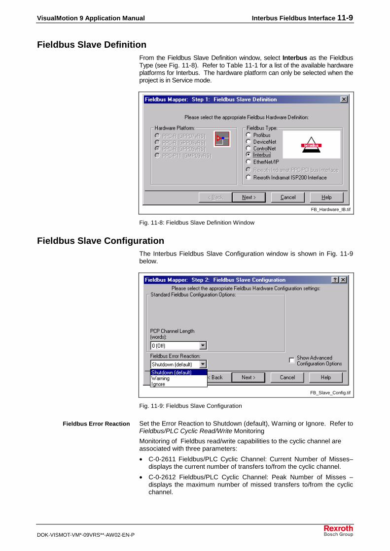
VisualMotion 9 Application Manual Interbus Fieldbus Interface 11-9
DOK-VISMOT-VM*-09VRS**-AW02-EN-P
Fieldbus Slave DefinitionFrom the Fieldbus Slave Definition window, select Interbus as the FieldbusType (see Fig. 11-8). Refer to Table 11-1 for a list of the available hardwareplatforms for Interbus. The hardware platform can only be selected when theproject is in Service mode.
FB_Hardware_IB.tif
Fig. 11-8: Fieldbus Slave Definition Window
Fieldbus Slave ConfigurationThe Interbus Fieldbus Slave Configuration window is shown in Fig. 11-9below.
FB_Slave_Config.tif
Fig. 11-9: Fieldbus Slave Configuration
Set the Error Reaction to Shutdown (default), Warning or Ignore. Refer toFieldbus/PLC Cyclic Read/Write Monitoring
Monitoring of Fieldbus read/write capabilities to the cyclic channel areassociated with three parameters:
• C-0-2611 Fieldbus/PLC Cyclic Channel: Current Number of Misses–displays the current number of transfers to/from the cyclic channel.
• C-0-2612 Fieldbus/PLC Cyclic Channel: Peak Number of Misses –displays the maximum number of missed transfers to/from the cyclicchannel.
Fieldbus Error Reaction

11-10 Interbus Fieldbus Interface VisualMotion 9 Application Manual
DOK-VISMOT-VM*-09VRS**-AW02-EN-P
• C-0-2613 Fieldbus/PLC Cyclic Channel: Timeout Counter – displaysthe number of timeouts in the cyclic channel. If after 4 ms, the CyclicMapping Lists are not successfully transmitted, a "miss" is noted.
For more information about these parameters, see the VisualMotion 9Functional Description manual.
Fieldbus Error Reaction on page 11-17 for detailed information abouteach setting.
The PCP (non-cyclic) channel can be set to 0 words (Off) or 2 words(On).
The Advanced Options field is displayed if the checkbox next to ShowAdvanced Configuration Options is checked (refer to Fig. 11-10 below).In most cases, the default options should apply.
FB_Slave_Config_Adv.tif
Fig. 11-10: Fieldbus Slave Configuration: Advanced
• Multiplex Method: select Primary or Secondary (Primary is thedefault). Select Secondary only if you have a consistent fieldbusmaster. Refer to Multiplexing on page 11-19 for detailed informationabout each method.
Cyclic Data ConfigurationAn example of the Cyclic Data Configuration window is shown in Fig. 11-11 below. If you are editing an existing Fieldbus Mapper file, the list willprobably contain more items.
First, you must select the Cyclic Input List (from PPC-R to PLC) or theCyclic Output List (from PLC to PPC-R).
PCP Channel Length
Advanced Configuration Options

VisualMotion 9 Application Manual Interbus Fieldbus Interface 11-11
DOK-VISMOT-VM*-09VRS**-AW02-EN-P
Cyclic_Data_Config.tif
Fig. 11-11: Cyclic Data Configuration
Adding an Item to the List1. Select the Cyclic Input List or the Cyclic Output List.
2. Click Add. The window in Fig. 11-12 below appears. Select the DataType (for example, Register).
Cyclic_Data_Add.tif
Fig. 11-12: Add Item to Cyclic Data
Note: Registers and 16-bit Multiplex Containers (used only forRegisters) require one data word (16 bits), and all other datatypes require two data words (32 bits) of space.
3. Enter the required information (for example Register Number) orselect it from the list below. Only the available data types for yourdesignated VisualMotion hardware setup and fieldbus type are listed.
Note: If your project is in Service mode and you check the box nextto “Get Latest (On-Line),” the data type label list is updatedbased on your firmware version and the currently activeprogram.
4. Click OK to add the selected item to the list.

11-12 Interbus Fieldbus Interface VisualMotion 9 Application Manual
DOK-VISMOT-VM*-09VRS**-AW02-EN-P
Adding Multiplex Containers to the List1. Select the Cyclic Input List or the Cyclic Output List.
2. Click Add.
3. In the Add Item window under Select the Data Type, select MultiplexContainer 16-bit (for Registers) or Multiplex Container 32-bit (for allother data types).
4. Click OK to add the Multiplex Container to the List. The window inFig. 11-13 below is an example where a 16-bit Multiplex Containerand a 32-Bit Multiplex Container have been added.
Cyclic_Data_Config_mltplx.tif
Fig. 11-13: Cyclic Data Configuration, Multiplex Containers
Note: At this point, the Multiplex Containers do not yet contain anyitems. To add multiplex items, refer to below.
Adding Items to an Empty Multiplex Container1. In the Cyclic Data Configuration window, select the multiplex
container to which you want to add items.
2. Click Add. The window in Fig. 11-14 below appears. Because it isunclear whether you would like to add to the list or to the multiplexcontainer, the Fieldbus Mapper is requesting clarification.
Add_Multiplex.tif
Fig. 11-14: Add Item or Multiplex Item

VisualMotion 9 Application Manual Interbus Fieldbus Interface 11-13
DOK-VISMOT-VM*-09VRS**-AW02-EN-P
Note: For subsequent items, highlight any of the indexes within themultiplex container before clicking Add, and the Fieldbus Mapper willknow you want to add to that container.
3. To add to the selected multiplex container, click No. The window inFig. 11-15 below is an example for adding a 32-bit multiplex item.
4. Select the desired item to be added to the multiplex container.
Note: In addition to the data types that can be added to the multiplexlist, an empty item called Multiplex Empty Item is available tofill a space within the multiplex container, if nothing is to bemapped to a particular index.
5. Click OK. The item is automatically placed in the multiplex containeras the next unassigned index item (e.g. the first item is index 00, thelast is index 31).
6. Repeat for as many items as you want to add to the multiplexcontainer, up to 32 items.
Add_Multiplex_Item.tif
Fig. 11-15: Adding a Multiplex Item to the Container (32-bit example)
Editing the Cyclic Data ListsTo make changes to an existing list, use the following buttons:
Button Function
Inserts a new item at the end of the list.
Inserts a new item into the list directly before the selected item.
Removes the selected item from the list.
Allows editing of the selected item. (To edit a list item, you mayalso double-click on it.)
Clears up the current list.
Table 11-3: Button Functions in the Cyclic Data Configuration Window

11-14 Interbus Fieldbus Interface VisualMotion 9 Application Manual
DOK-VISMOT-VM*-09VRS**-AW02-EN-P
Additional FunctionsSeveral additional functions are available in the Fieldbus Mapper:
Menu Item Function
Print Print the current fieldbus configuration data.
Print Preview Preview the printout of the current fieldbusconfiguration data
Print Setup Configure printer settings
Table 11-4: Additional Functions
Getting the Fieldbus Configuration from the PPCAfter getting the fieldbus configuration from the PPC, the followinginformation is detected by the system and appears in the configuration list:
• Fieldbus Type Found
• Fieldbus FW (Firmware) Version
• GPP Control FW (Firmware) Version
An example is shown in Fig. 11-16 below.

VisualMotion 9 Application Manual Interbus Fieldbus Interface 11-15
DOK-VISMOT-VM*-09VRS**-AW02-EN-P
On-Line Information
on-line info_IB.tif
Fig. 11-16: On-Line Fieldbus Configuration Information
11.3 Information for the GPP Programmer
Fieldbus StatusVisualMotion Register 19 holds the information for "Fieldbus Status." Theregister information can be referenced in a VisualMotion applicationprogram to respond to the status of each bit. The use of these bits isapplication-dependent.
Table 11-5 below contains the bit assignment for the fieldbus status. Theassigned bits are labeled with "x" and the bit number in the second row.Unassigned bits are labeled with "---."
16 15 14 13 12 11 10 9 8 7 6 5 4 3 2 1
--- x15 --- --- --- --- --- --- --- --- --- x5 x4 --- x2 x1
Table 11-5: Bit Assignment for VisualMotion Register 19

11-16 Interbus Fieldbus Interface VisualMotion 9 Application Manual
DOK-VISMOT-VM*-09VRS**-AW02-EN-P
Bit DefinitionsStatus bits for the internal DPR (Dual-Port RAM) communication betweenthe fieldbus slave and the PPC-R:
x1: FB Init. OK , LSB (least significant bit)
x2: FB Init. OK, MSB (most significant bit)
The bit combinations for x1 and x2 are as follows:
Bit 2(PPC-R)
Bit 1(Fieldbus)
Description
0 0 A reset has been executed on the DPR,orneither the PPC-R nor the fieldbus cardhave initialized the DPR.
0 1 The DPR is initialized by the fieldbus card,but not yet by the PPC-R.
1 0 The DPR initialization is complete. DPRhas been initialized by the fieldbus cardand PPC-R. Fieldbus to PPC-Rcommunications system is ready.
1 1 Fieldbus to PPC-R communications systemis ready.
Table 11-6: Possible Settings for Bits 1 and 2, Status Bits for DPRCommunication
Status bit for the active bus capabilities of the fieldbus slaves (FB SlaveReady)
0--> The fieldbus slave is not (yet) ready for data exchange.
1--> The fieldbus slave can actively participate on the bus.
Status bit for the non-cyclic (PCP) channel (Non-Cyc Ready)
0--> The non-cyclic channel cannot (yet) be used.
1--> The non-cyclic channel is ready for use by the fieldbus master.
Status bit for the cyclic data output (Cyclic Data Valid):
0--> The cyclic data outputs (coming in to the PPC-R) are INVALID.
1--> The cyclic data outputs (coming in to the PPC-R) are VALID. Thesystem looks for this bit to be 1 before allowing data transfer.
This bit is monitored for the Fieldbus Error Reaction. Whenever this bitgoes to 0 after a fieldbus card was initially found by the PPC-R, theselected Error Reaction (system shutdown, error message, or ignore) isinitiated. Refer to Fieldbus/PLC Cyclic Read/Write Monitoring
Monitoring of Fieldbus read/write capabilities to the cyclic channel areassociated with three parameters:
• C-0-2611 Fieldbus/PLC Cyclic Channel: Current Number of Misses–displays the current number of transfers to/from the cyclic channel.
• C-0-2612 Fieldbus/PLC Cyclic Channel: Peak Number of Misses –displays the maximum number of missed transfers to/from the cyclicchannel.
• C-0-2613 Fieldbus/PLC Cyclic Channel: Timeout Counter – displaysthe number of timeouts in the cyclic channel. If after 4 ms, the CyclicMapping Lists are not successfully transmitted, a "miss" is noted.
For more information about these parameters, see the VisualMotion 9Functional Description manual.
Fieldbus Error Reaction on page 11-17 for an explanation of the FieldbusError Reaction setting.
x1, x2
x4
x5
x15

VisualMotion 9 Application Manual Interbus Fieldbus Interface 11-17
DOK-VISMOT-VM*-09VRS**-AW02-EN-P
Fieldbus DiagnosticsVisualMotion Register 20 holds the information for "Fieldbus Diagnostics."
Table 11-7 below contains the bit assignment for the diagnostics. Theassigned bits are labeled with "x" and the bit number in the second row.Unassigned bits are labeled with "---."
16 15 14 13 12 11 10 9 8 7 6 5 4 3 2 1
X16 x15 x14 x13 --- --- --- --- --- --- --- --- --- --- --- ---
Table 11-7: Bit Assignment for VisualMotion Register 20
Bit DefinitionsIdentification of the fieldbus interface card (FB Card Found)
The bit combinations for x13, x14 and x15 are as follows:
Bit 16 Bit 15 Bit 14 Bit 13 Fieldbus Type
0 0 0 0 <NO CARD>
0 0 0 1 <Not Defined>
0 0 1 0 Interbus
0 0 1 1 DeviceNet
0 1 0 0 Profibus
0 1 0 1 ControlNet
0 1 1 0 <Not Defined>
0 1 1 1 EtherNet/IP (10 MB)
1 1 1 1 Indramat PLC Interface
Table 11-8: Identification of the Fieldbus Interface
Fieldbus/PLC Cyclic Read/Write MonitoringMonitoring of Fieldbus read/write capabilities to the cyclic channel areassociated with three parameters:
• C-0-2611 Fieldbus/PLC Cyclic Channel: Current Number of Misses–displays the current number of transfers to/from the cyclic channel.
• C-0-2612 Fieldbus/PLC Cyclic Channel: Peak Number of Misses –displays the maximum number of missed transfers to/from the cyclicchannel.
• C-0-2613 Fieldbus/PLC Cyclic Channel: Timeout Counter – displaysthe number of timeouts in the cyclic channel. If after 4 ms, the CyclicMapping Lists are not successfully transmitted, a "miss" is noted.
For more information about these parameters, see the VisualMotion 9Functional Description manual.
Fieldbus Error Reaction
Note: The Fieldbus Error Reaction setting is active only in SERCOSPhase 4. In all other SERCOS phases, it will be inactive.
You can select how you would like the PPC-R system to react in case of afieldbus error. This reaction can be set in the "Fieldbus SlaveConfiguration" window, using the combo box labeled "Fieldbus ErrorReaction."
Three options are available for the Error Reaction setting. Depending onthe selected setting, the value 0, 1, or 2 is stored in Parameter C-0-2635:
x13 - x16

11-18 Interbus Fieldbus Interface VisualMotion 9 Application Manual
DOK-VISMOT-VM*-09VRS**-AW02-EN-P
Setting Value in Parameter C-0-2635
Shutdown 0 (default)
Warning Only 1
Ignore 2
Table 11-9: Parameter C-0-2635 Values for Error Reaction Settings
Fieldbus Mapper TimeoutThe Fieldbus Mapper continually scans the system for sufficientresources to process the cyclic data mapping lists (2600 and 2601 lists).If 10 out of 10 consecutive attempts of the mapping list updates areincomplete, the system is considered to have insufficient resources andthe selected error reaction is evoked, as follows:
If "Shutdown" (0) is set in Parameter C-0-2635, the following error isgenerated from the PPC-R card: 520 Fieldbus Mapper Timeout
If "Warning Only" (1) is set in Parameter C-0-2635, the following error isgenerated: 209 Fieldbus Mapper Timeout
If "Ignore" (2) is set in Parameter C-0-2635, the system will update asresources become available, but there is no way to monitor whether or notupdates actually occur.
Lost Fieldbus ConnectionRegister 19, bit 4 indicates the status of the fieldbus. Refer to FieldbusStatus on page 11-15 for more specific bit information. The systemmonitors this bit and evokes the selected error reaction if the bit is low (0),after a fieldbus card is found. A typical situation that will cause thiscondition is the disconnection of the fieldbus cable from the fieldbus card.
If "Shutdown Control" (0) is set in Parameter C-0-2635, the following erroris generated from the PPC-R (active in SERCOS Phase 4 only):519 Lost Fieldbus Connection
If "Warning Only" (1) is set in Parameter C-0-2635, the following error isgenerated (active in SERCOS Phase 4 only):208 Lost Fieldbus Connection
If "Ignore" (2) is set in Parameter C-0-2635, there is no noticeablereaction when Register 19 status bits go low, unless the GPP applicationprogram is customized to evoke a special reaction.
Troubleshooting Tip:
If a fieldbus card is not found on the system, the ErrorReaction setting will be ignored. If you have a fieldbus cardand the Error Reaction is not responding as expected, thesystem may not "see" your fieldbus card.

VisualMotion 9 Application Manual Interbus Fieldbus Interface 11-19
DOK-VISMOT-VM*-09VRS**-AW02-EN-P
11.4 Information for the PLC Programmer
Important: The fieldbus master's access of the cyclic channel must beconsistent over the entire channel length in order to establishreliable multiplexing communications.
Multiplexing
Primary Multiplex Method (for Inconsistent Masters)
Explanation of the Master Consistency ProblemThe PPC-R fieldbus slave interfaces can guarantee consistency,however, some fieldbus masters can only guarantee byte, word or doubleword consistency. If the master is only word-consistent, it is possible thatthe master cannot transfer the data and the control word of one multiplexindex consistently from the PLC to the fieldbus. Therefore, it is necessaryto have a second multiplex method where both input data and output datarequire the handshake bits to update via the fieldbus.
Fig. 11-17 below illustrates the control word definition for the PrimaryMultiplex Method.
Multiplex Input Control Index(index_in_c)
(defines the input index command formultiplexing)
15 14 13 12 11 10 9 8 7 6 5 4 3 2 1 0
Multiplex Output Control Index(index_out_c)
(defines the output index command formultiplexing)
Write RequestToggle Bit (WR)
(initiates the writecommand once each
time it is toggled)
RRsee definition
under “HandshakeBits WR / WA and
RR / RA”(Secondary
Method only)
Multiplex Input Control Byte Multiplex Output Control Byte
Fig. 11-17: Control Word Definition, Primary Multiplex Method
15 14 13 12 11 10 9 8 7 6 5 4 3 2 1 0
Multiplex Input Status Index(index_in_s)
(confirms that the input index responselocation matches that of the command
location)
RAsee definition
under “HandshakeBits WR / WA and
RR / RA”(Secondary
Method only)
Multiplex Output Status Index(index_out_s)
(confirms that the output index responselocation matches that of the command
location)
Write RequestAcknowledge Bit
(WA)(checks that the writedata has been readonce each time it is
toggled)
Multiplex Input Status Byte Multiplex Output Status Byte
Fig. 11-18: Status Word Definition, Primary Multiplex Method
The Primary Multiplex Method has the following features:
• You can transfer a different index from master to slave as fromslave to master.
• The handshake bits for both reading and writing of this multiplexchannel make the multiplexing possible on inconsistent systems(masters).

11-20 Interbus Fieldbus Interface VisualMotion 9 Application Manual
DOK-VISMOT-VM*-09VRS**-AW02-EN-P
Handshake Bits WR and WAWR and WA are handshake bits that allow the controlled writing of datavia the multiplex channel. WR and WA control the data transfer forwriting data_out (data send from master to slave).WR == WA:
• tells the master that the slave has received the last multiplex data_out.The master can now send new data_out.
• tells the slave to do nothing, because the master has not yet put newconsistent data_out on the bus.
WR! = WA:
• tells the slave to do something, because the master has now putconsistent new data_out on bus.
• tells the master to do nothing, because the slave has not yet receivedthe latest multiplex data_out.
Handshake Bits RR and RARR (Read Request) and RA (Read Acknowledge) are handshake bits thatallow a controlled data transfer and use of the multiplex channel oninconsistent masters. RR and RA control the data transfer for readingdata_in (data send from slave to master).
RR == RA:
• tells the master that the slave has sent the requested data_in. Themaster can now read the data_in and request new data_in.
• tells the slave to do nothing, because the master has not yet put newconsistent data on the bus.
RR != RA:
• tells the slave to put new data_in on the bus, because the masterrequests new data_in.
• tells the master to do nothing, because the slave has not yet put thelatest requested multiplex data_in on the bus.
Master Communications (Primary Multiplex Method)
Begin
Control Word =0
RR==RA ? Read Index_in_s,Read Data_in,
Write Index_in_cYes
No
WR == WA ?
Yes
No
Write Data_out,Write Index_out_c,
Toggle WRT (Set WR = ~WA)
Read Data_in
Write Data_out
Toggle RRT (Set RR = ~RA)
*1there may be different ways to achieve consistency, depending on the master
Fig. 11-19: Primary Multiplex Method, Master Communications
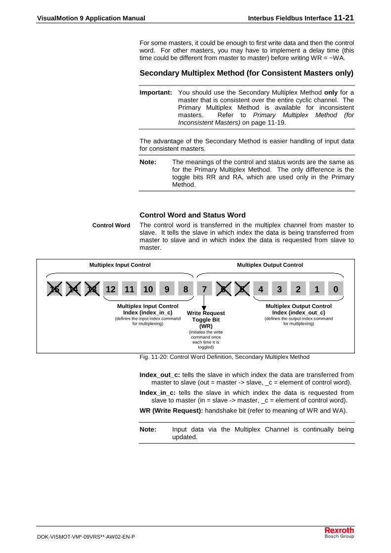
VisualMotion 9 Application Manual Interbus Fieldbus Interface 11-21
DOK-VISMOT-VM*-09VRS**-AW02-EN-P
For some masters, it could be enough to first write data and then the controlword. For other masters, you may have to implement a delay time (thistime could be different from master to master) before writing WR = ~WA.
Secondary Multiplex Method (for Consistent Masters only)
Important: You should use the Secondary Multiplex Method only for amaster that is consistent over the entire cyclic channel. ThePrimary Multiplex Method is available for inconsistentmasters. Refer to Primary Multiplex Method (forInconsistent Masters) on page 11-19.
The advantage of the Secondary Method is easier handling of input datafor consistent masters.
Note: The meanings of the control and status words are the same asfor the Primary Multiplex Method. The only difference is thetoggle bits RR and RA, which are used only in the PrimaryMethod.
Control Word and Status WordThe control word is transferred in the multiplex channel from master toslave. It tells the slave in which index the data is being transferred frommaster to slave and in which index the data is requested from slave tomaster.
15 14 13 12 11 10 9 8 7 6 5 4 3 2 1 0
Multiplex Output ControlIndex (index_out_c)
(defines the output index commandfor multiplexing)
Write RequestToggle Bit
(WR)(initiates the writecommand onceeach time it is
toggled)
Multiplex Input ControlIndex (index_in_c)
(defines the input index commandfor multiplexing)
Multiplex Input ControlByte
Multiplex Output ControlByte
Fig. 11-20: Control Word Definition, Secondary Multiplex Method
Index_out_c: tells the slave in which index the data are transferred frommaster to slave (out = master -> slave, _c = element of control word).
Index_in_c: tells the slave in which index the data is requested fromslave to master (in = slave -> master, _c = element of control word).
WR (Write Request): handshake bit (refer to meaning of WR and WA).
Note: Input data via the Multiplex Channel is continually beingupdated.
Control Word
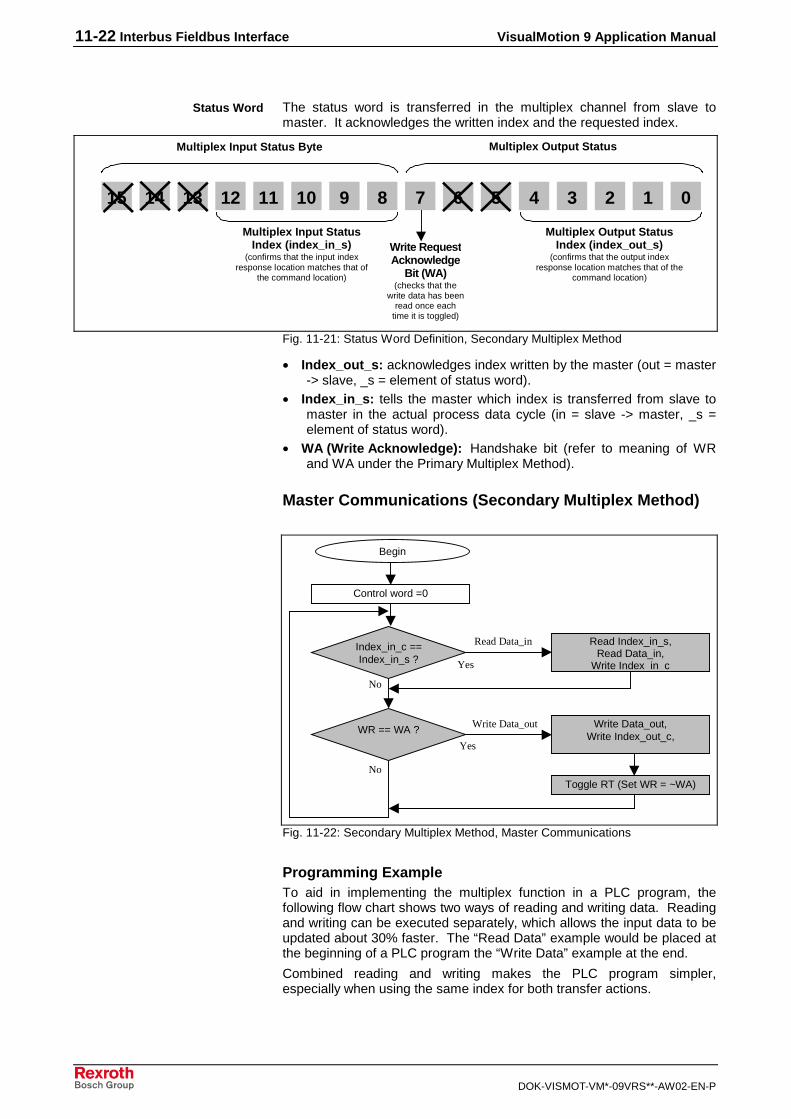
11-22 Interbus Fieldbus Interface VisualMotion 9 Application Manual
DOK-VISMOT-VM*-09VRS**-AW02-EN-P
The status word is transferred in the multiplex channel from slave tomaster. It acknowledges the written index and the requested index.
15 14 13 12 11 10 9 8 7 6 5 4 3 2 1 0
Multiplex Input StatusIndex (index_in_s)
(confirms that the input indexresponse location matches that of
the command location)
Multiplex Output StatusIndex (index_out_s)
(confirms that the output indexresponse location matches that of the
command location)
Write RequestAcknowledge
Bit (WA)(checks that the
write data has beenread once each
time it is toggled)
Multiplex Input Status Byte Multiplex Output StatusByte
Fig. 11-21: Status Word Definition, Secondary Multiplex Method
• Index_out_s: acknowledges index written by the master (out = master-> slave, _s = element of status word).
• Index_in_s: tells the master which index is transferred from slave tomaster in the actual process data cycle (in = slave -> master, _s =element of status word).
• WA (Write Acknowledge): Handshake bit (refer to meaning of WRand WA under the Primary Multiplex Method).
Master Communications (Secondary Multiplex Method)
Begin
Control word =0
Index_in_c ==Index_in_s ?
Read Index_in_s,Read Data_in,
Write Index_in_c
WR == WA ? Write Data_out,Write Index_out_c,
Toggle RT (Set WR = ~WA)
Read Data_in
Write Data_out
Yes
No
Yes
No
Fig. 11-22: Secondary Multiplex Method, Master Communications
Programming ExampleTo aid in implementing the multiplex function in a PLC program, thefollowing flow chart shows two ways of reading and writing data. Readingand writing can be executed separately, which allows the input data to beupdated about 30% faster. The “Read Data” example would be placed atthe beginning of a PLC program the “Write Data” example at the end.
Combined reading and writing makes the PLC program simpler,especially when using the same index for both transfer actions.
Status Word

VisualMotion 9 Application Manual Interbus Fieldbus Interface 11-23
DOK-VISMOT-VM*-09VRS**-AW02-EN-P
���������
���
�0
��#!��2�"'!�2���A
��#!��0'!"'!���!�! �+')!#")�A�& �!�#���=�>
��#!��0'!"'!�2���A
� $$)����#!���B'��!�.#!
�0
���
��������
#��
��������������
���������! ��2�"'!���!��*� 6
+C")�A�& �!�#���=�>
��!�/
:&�&;<)�
����/:&
�&;<)�
��#!��0'!"'!���!�! �+')!#")�A�& �!�#���=�>
+C")�A2�"'!
& �!� )�.;!�1
+C")�A�2�"'!�!�!'�.;!�D
+C")�A& �!� )� ��
+C")�A�!�!'�� ��D
���������! ��2�"'!���!��*� 6
+C")�A�& �!�#���=�>
+C")�A0'!"'!
& �!� )�.;!�1
+C")�A�0'!"'!�!�!'�.;!�D
��#!��2�"'!����0'!"'!�2���A��
� $$)����#!���B'��!�.#!
�0
1
multiplexing flow chart.FH7
Fig. 11-23: Flow Chart of Multiplex Programming Examples (Secondary Method)
Non-Cyclic Data Access via the Non-Cyclic (PCP) ChannelTo support the configuration of drives and the access to parameters viaInterbus, Rexroth supports the PCP channel.
Note: The PCP Channel is fixed at a length of 2 words whenenabled.
To read or write a VisualMotion data type non-cyclically, a special set ofpre-defined objects is used in the PCP channel. Refer to thedocumentation provided by the fieldbus manufacturer for access andsupport of the PCP channel.
The following methods for transferring data are available in the PCPchannel:
• Mapped Data
• Data Exchange Objects
Mapped DataMapped data is the most powerful feature of the PPC-R non-cyclicfieldbus interface. Through mapped data, the user has access to virtuallyevery PPC-R data type over the fieldbus. It is easy to implement from thePLC side and requires no setup on the PPC-R side.
To access a data type over the fieldbus, it has to be specified by anaddress that consists of an index and a subindex. The index andsubindex for each data type can be calculated by a formula (refer toAccessing Mapped Data on page 11-27).

11-24 Interbus Fieldbus Interface VisualMotion 9 Application Manual
DOK-VISMOT-VM*-09VRS**-AW02-EN-P
�A�����A����
�A�����A����
�?/���6�!���
/?/���6�!���
�A�����A���� �A#�?
/���6�!���
9#�)�4'�04E�<!�
�#�'�)+ !# ���!�
�'42���A
��#(��,2���A
�A#��,
�?�
�?����
/?����
/?�
�?�
�?����
object_mapping_PB_IB.FH7
Fig. 11-24: Mapped Data
Mapped data can be used with the following parameters and values:
• S-Parameters (SERCOS Drive S-Parameters)
• P-Parameters (SERCOS Drive P-Parameters)
• A-Parameters (PPC Axis Parameters)
• C-Parameters (PPC C System parameters)
• T-Parameters (PPC Task parameters)
size and
formatdepend on
parameter *,1
PF-Values (PPC Program Float data, 32 bit – 2 words, IEEE format) *,2
GI-Values (PPC Global Integer data, 32 bit – 2 words) *,2
GF-Values (PPC Global Float data, 32 bit – 2 words, IEEE format) *,2
PI-Values (PPC Program Integer data, 32 bit – 2 words) *,2
Reg.-Values (PPC Register data, 16 bit – 1 word) *,3
Data Exchange Objects (0x5E70 – 0x5E73) (embedded ASCII Protocol)
*You may notice that parameters accessed via the non-cyclic (Parameter) channel are not always the samesize as reported from the attribute field. This is so that the data sizes correspond with the way the different datatypes are handled in the cyclic channel (Registers are always set to 16-bit size and Parameters are cast to 32-bit size, even if they actually use less space).
1. When writing mapped data to a VisualMotion Parameter, you must send the size datacorresponding to that of the attribute field within the parameter.
a.) For 32-bit parameters, you must send a data size of 32 bits (otherwise, VM error #07 isreturned).
b.) For 16-bit parameters, you must send a data of size 16-bits. If, for this case, you send data ofsize 32 bits, one of the following occurs:
i.) For parameters of type 16-bit unsigned, only the Low word is stored, and the High word isignored.

VisualMotion 9 Application Manual Interbus Fieldbus Interface 11-25
DOK-VISMOT-VM*-09VRS**-AW02-EN-P
ii.) For parameters of type 16-bit signed, bits 0-14 of the low word along with the sign bit #31are used, and the remaining bits are ignored.
c.) For String Parameters (e.g. S-0-0142), you must send the size of the string to write.
d.) All other Parameter Types (list parameters, command parameters, etc), are not supported formapped data.
When reading mapped data from a VisualMotion Parameter, there are 3 possible cases of sizesreturned:
a.) If the parameter type is a string, you receive the number of bytes corresponding to the length ofthe string.
b.) If the parameter is 32-bit or less, you receive a cast 32-bit value for this parameter. This impliesthat 16-bit parameters are returned as cast in to 32-bit values.
c.) All other parameter types (e.g. list parameters, command parameters, etc.), are not supportedfor mapped data.
2. When writing mapped data to a VisualMotion Program Float, Program Integer, Global Float, orGlobal Integer, the data size must be 32-bits (2 words). Any other size returns a VM error #07(Invalid Data Format).
When reading mapped data from a VisualMotion Program Float, Program Integer, Global Float, orGlobal Integer, the data size returned is always 32-bit (2 words).
3. When writing mapped data to a VisualMotion Register, the data must be 16-bits (1 word). Any othersize returns a VM error #07 (Invalid Data Format).
When reading mapped data from a VisualMotion Register, the data size returned is always 16-bit (1 word).
The index refers to the particular fieldbus slave object that a VisualMotiondata type is (automatically) mapped. This object allows for simple,indirect access to VisualMotion data types, and it is combined with thesubindex to create a direct relationship to the VisualMotion data types.The available objects can be calculated using the formulas in AccessingMapped Data on page 11-27.
The subindex refers to an additional piece of information necessary toobtain direct access to VisualMotion data types. The reference of thesubindex depends on the data type in question. For example, theSubIndex refers to the drive number when accessing S and Pparameters. However, the subindex refers to the task number whenreferring to task parameters. The available subindex ranges can becalculated using the formulas in Accessing Mapped Data on page 11-27.
Data Exchange ObjectsThe four data exchange objects 5E70 to 5E73 represent fixed data"containers" of varying lengths that transfer the VisualMotion ASCII Protocol tothe PPC-R card. These objects serve as an open-ended possibility to accessany VisualMotion data (including cams, diagnostic text, etc.), but more work isrequired in the master to perform a transmission of this type. Both theVisualMotion ASCII message and the fieldbus transfer message must beformulated.
Table 11-10 lists the available data exchange objects and their sizes.
Data Exchange Object Data Length (in bytes)
5E70 16
5E71 32
5E72 64
5E73 128
Table 11-10: Length of the Data Exchange Objects
Handling a Data Exchange ObjectWhen mapped objects are not capable of transferring the desired data, aData Exchange Object can be used.
The same procedures for writing and reading data apply to the DataExchange Object.
Object Index
Object SubIndex

11-26 Interbus Fieldbus Interface VisualMotion 9 Application Manual
DOK-VISMOT-VM*-09VRS**-AW02-EN-P
Selecting a Data Exchange ObjectDepending on the length of a VisualMotion ASCII message, any of thesedata exchange objects can be selected.
Note: The entire data length of the data exchange object mustalways be transmitted even if the VisualMotion ASCII messageis shorter.For example, if you want to transmit an ASCII message of 42bytes, you must use object 5E72. To avoid a response errorfrom the fieldbus slave, you must append 22 "Null" charactersto the end of the ASCII message to complete a data size of 64bytes.
Note: The checksum for the VisualMotion ASCII protocol is NOTused with the data exchange object. If the checksum is sentas part of the string, it will be ignored, and no checksum will besent in the VisualMotion ASCII response messages. Toensure data integrity, the fieldbus protocols support a low-levelchecksum.
Transmission Sequence via a Data Exchange Object
Note: For the data exchange object, two transmission sequences(and two response sequences) are required, to send the reador write message to and then receive the response messagefrom the PPC-R card.
PCPControlWord VisualMotion ASCII Protocol
key components:• Object Index #:
data exchangeobject(5E70-5E73).This is thedestination of thedata field. Objectselectiondepends onrequired data fieldsize.
• Subindex #:always = 0 forData ExchangeObject.
key components:• VisualMotion command
(read or write data)
• ASCII data contained in theselected data exchange object
• The <CR> (0x0D) and <LF>(0x0A) characters must beapplied to the ASCII string
• A checksum is not used in thiscase. (Fieldbus has a checksum)
Note: Refer to the VisualMotion 6Reference Manual for an explanationof the VisualMotion ASCII Protocol.
Data Field:
PCP Channel Message
key components:• fieldbus
command(read or writemessage)
Object Index # Subindex #
PCP Header
Fig. 11-25: Format of a PCP Channel Message using a Data Exchange Object
For information about reading and writing data using the PCP channel,consult the documentation provided by the fieldbus manufacturer.

VisualMotion 9 Application Manual Interbus Fieldbus Interface 11-27
DOK-VISMOT-VM*-09VRS**-AW02-EN-P
VM ASCII protocolcommand text
(read or write data)
Received?PCP Response No
Yes
OK?PCP Response No
Yes
No data
Received?PCP Response No
Yes
OK?PCP Response No
Yes
VM ASCII protocolresponse text
(write or transmit data)
Message Steps Process Comments
4. Receive PCP Channelresponse from slave.
PCP Read Command
PCP Write Command1. Write request from themaster with VisualMotionASCII Protocol.
2. Acknowledge PCP Channelresponse from slave.
3. Read request from themaster to get VisualMotionASCII response.
The data field for the writecommand can contain aVisualMotion read or writeprotocol.
The response message containsonly a confirmation that thefieldbus message was sentproperly. Therefore, the size ofthe data field will be 0.
The read request messagecontains only header information(the data field is 0). You mustanticipate the approximate sizeof the data field (VisualMotionASCII response message) inorder to select the appropriatedata exchange object. If theselected object is too short, thedata will be truncated.
The response message willcontain the VisualMotion ASCIIresponse to the VisualMotionASCII command text in Step 1.
Diagnoseerror
Diagnoseerror
Fig. 11-26: PCP Channel Procedure, Using Data Exchange Object
Accessing Mapped Data (via the PCP Channel)Rexroth has pre-configured a number of VisualMotion data types to Interbusindexes and subindexes. We call this concept mapped data. These datatypes can be accessed via the Interbus PCP Channel. The index andsubindex for each of these data types can be calculated using the formulas inTable 11-11 below.

11-28 Interbus Fieldbus Interface VisualMotion 9 Application Manual
DOK-VISMOT-VM*-09VRS**-AW02-EN-P
ObjectIndex # SubIndex # Formula
0x5E73 0x00
Data Exchange Object ---- ----
0x5E70 0x00
0x5E65 0xFF
<FREE> ---- ---- (with SubIndex)
(349 objects available) 0x5D14 0x01
0x5D13 0xFF Index = 0x5D00 + [(Program Integer –1) \ 255]
Program Integers ---- ----
(Int 1 – Int 5100) 0x5D00 0x01 SubIndex = Program Integer – [(Index – 0x5D00) * 255]
0x5CFF 0xFF Index = 0x5CEC + [(Program Float –1)] \ 255]
Program Floats ---- ----
(Float 1 – Float 5100) 0x5CEC 0x01 SubIndex = Program Float – [(Index – 0x5CEC) * 255]
0x5CEB 0xFF
<FREE> ---- ---- (with SubIndex)
(235 objects available) 0x5C01 0x01
0x5C00 0xFF Index = 0x5BF7 + [(Global Integer – 1) \ 255]
Global Integers ---- ----
(GInt 1 – GInt 2550*) 0x5BF7 0x01 SubIndex = Global Integer – [(Index – 0x5BF7) * 255]
0x5BF6 0xFF Index = 0x5BED + [(Global Float – 1) \ 255]
Global Floats ---- ----
(GFloat 1 – Gfloat 2550*) 0x5BED 0x01 SubIndex = Global Float – [(Index – 0x5BED) * 255]
0x5BEC 0xFF
<FREE> ---- ---- (with SubIndex)
(245 objects available) 0x5AF8 0x01
0x5AF7 0xFF Index = 0x5AEE + [(Register – 1) \ 255]
Registers ---- ----
(Reg. 1 – Reg. 2550**) 0x5AEE 0x01 SubIndex = Register – [(Index – 0x5AEE) * 255]
0x5AED 0x04 Index = 0x56F1 + T-Parameter
T-Parameters ---- ----
(T-0-0001 – T-0-1020) 0x56F1 0x01 SubIndex = Task Number
0x56F0 0xFF
<FREE> ---- ---- (with SubIndex)
(241 objects available) 0x5600 0x01
0x55FF 0x01 Index = 0x4800 + C-Parameter
C-Parameters ---- ----
(C-0-0001 - C-0-3583) 0x4801 0x01 SubIndex = 1
0x47FF 0x63 Index = 0x4000 + A-Parameter
A-Parameters ---- ----
(A-0-0001 - A-0-2047) 0x4001 0x01 SubIndex = Axis Number
0x3FFF 0x63 Index = 0x3000 + P-Parameter
P-Parameters ---- ----
(P-0-0001 - P-0-4095) 0x3001 0x01 SubIndex = Drive Number

VisualMotion 9 Application Manual Interbus Fieldbus Interface 11-29
DOK-VISMOT-VM*-09VRS**-AW02-EN-P
ObjectIndex # SubIndex # Formula
0x2FFF 0x63 Index = 0x2000 + S-Parameter
S-Parameters ---- ----
(S-0-0001 - S-0-4095) 0x2001 0x01 SubIndex = Drive Number
0x1FFF ----
<Reserved> ---- ----
0x0000 ----
* current limitation: C-0-0080/C-0-0081 – Maximum number global integers/floats
**current limitation: first 1024 registers.
Table 11-11: Formulas for Determining Mapped Objects
Example Lookup Tables for Mapped ObjectsThe following is an example lookup table for C-Parameters, when usingmapped objects.
Example Look-up Chart for: C-Parameters CP 0.Y ==> CP = Card Parameter
Y = Parameter Number
Index
0x4801 0x4802 0x4803 …………… 0x48FF 0x4900 …………… 0x55FE 0x55FF
SubIndex = 0x01 CP 0.1 CP 0.2 CP 0.3 CP 0.255 CP 0.256 CP 0.3582 CP 0.3583
Table 11-12: Mapped Object Lookup Table for C-Parameters
The following is an example lookup table for A-Parameters, when usingmapped objects. The same formula also applies to SERCOS (S) andTask (T) Parameters.
Example Look-up Chart for: A-Parameters AP X.Y ==> AP = Axis Parameter
X = Axis Number
Y = Parameter Number
Index
0x4001 0x4002 0x4003 ……………
0x40FF 0x4100 …………… 0x47FE 0x47FF
0x01 AP 1.1 AP 1.2 AP 1.3 AP 1.255 AP 1.256 AP 1.2046 AP 1.2047
SubIndex = 0x02 AP 2.1 AP 2.2 AP 2.3 AP 2.255 AP 2.256 AP 2.2046 AP 2.2047
0x03 AP 3.1 AP 3.2 AP 3.3 AP 3.255 AP 3.256 AP 3.2046 AP 3.2047
: : : : : : : : : :
: : : : : : : : : :
0x28 AP 40.1 AP 40.2 AP 40.3 AP 40.255 AP 40.256 AP 40.2046 AP 40.2047
Table 11-13: Mapped Object Lookup Table for A-Parameters
The following is an example lookup table for P-Parameters, when usingmapped objects.
Card (C) Parameters
Axis(A) Parameters
Product-Specific (P) Parameters

11-30 Interbus Fieldbus Interface VisualMotion 9 Application Manual
DOK-VISMOT-VM*-09VRS**-AW02-EN-P
Example Look-up Chartfor:
P-Parameters PP X.Y ==> PP = SERCOS P-Parameter (set 0 only)
X = Drive Number
Y = Parameter Number
Index = (Class ID && Instance ID for DeviceNet)
C118, In1 C118, In2 C118, In3 …………… C118, In255 C119, In1 …………… C134, In14 C134, In15
0x3001 0x3002 0x3003 …………… 0x30FF 0x3100 …………… 0x3FFE 0x3FFF
0x01 PP 1.1 PP 1.2 PP 1.3 PP 1.255 PP 1.256 PP 1.4094 PP 1.4095
SubIndex = 0x02 PP 2.1 PP 2.2 PP 2.3 PP 2.255 PP 2.256 PP 2.4094 PP 2.4095
(Attribute ID 0x03 PP 3.1 PP 3.2 PP 3.3 PP 3.255 PP 3.256 PP 3.4094 PP 3.4095
for DNet) : : : : : : : : : :
: : : : : : : : : :
0x28 PP 40.1 PP 40.2 PP 40.3 PP 40.255 PP 40.256 PP 40.4094 PP 40.4095
Table 11-14: Mapped Object Lookup Table for P-Parameters
The following is an example lookup table for Integers, when usingmapped objects. The same formula also applies to Floats, GlobalIntegers, Global Floats and Registers.
Example Look-up Chart for: VM Program Integers PI 0.Y ==> PI = Program Integer
Y = Program Integer Number
Index
0x5D00 0x5D01 0x5D02 …………… 0x5D13
0x01 PI 1 PI 256 PI 511 PI 4846
SubIndex = 0x02 PI 2 PI 257 PI 512 PI 4847
0x03 PI 3 PI 258 PI 513 PI 4848
: : : : : :
: : : : : :
0xFF PI 255 PI 510 PI 765 PI 5100
Table 11-15: Mapped Object Lookup Table for Integers
Integers

VisualMotion 9 Application Manual Index 12-1
DOK-VISMOT-VM*-09VRS**-AW02-EN-P
12 Index
"
"Lock On/Lock Off"Lock Off Cam Profile .......6-52Lock On Cam Profile .......6-52Lock On Offset.................6-55
*
*.eds file.............................10-22*.gsd file...............................9-18
2
208 Lost Fieldbus Connection...................... 9-17, 10-21, 11-18
209 Field Bus Mapper Timeout.................. 9-17, 10-21, 11-18
5
519 Lost Fieldbus Connection...................... 9-17, 10-21, 11-18
520 Field Bus Mapper Timeout.................. 9-17, 10-21, 11-18
5E70 .........................9-26, 11-255E71 .........................9-26, 11-255E72 .........................9-26, 11-255E73 .........................9-26, 11-25
A
Acceleration profiles ..............4-2
B
Base Code instruction ...........7-2Baud Rate ................... 3-3, 3-39Bit Definitions
Register 19Cyclic Data Valid .................
........... 9-16, 10-19, 11-16FB Init OK............................
........... 9-15, 10-19, 11-16FB Slave Ready ..................
........... 9-15, 10-19, 11-16Non-Cyc Ready...................
........... 9-16, 10-19, 11-16Register 20
FB Card Found............................... 9-16, 10-20, 11-17
Bit Labels.............................5-24Bumpless Transition............6-40Buttons
Add ........... 9-13, 10-17, 11-13Delete ....... 9-13, 10-17, 11-13Edit............ 9-13, 10-17, 11-13Insert......... 9-13, 10-17, 11-13New........... 9-13, 10-17, 11-13
Byte Swapping...................10-13
C
C-0-2635.......9-17, 10-21, 11-17Cam synchronization ............ 4-2Cascading ELS Groups ...... 6-28channels
Cyclic Data Channelconfiguration ......... 9-3, 10-3
multiplex ................... 9-2, 10-3Non-Cyclic Channel......... 10-3Parameter Channel ........... 9-2Real-Time Channel .... 9-2, 9-4single........................ 9-2, 10-3
CIF Hardware Loopback Test............................................ 3-24
CLC Compiler Base Code .... 7-2CLC_DDE ........................... 3-33Commissioning tools............. 5-3Communication Servers ....... 3-1
SCP................................... 3-1VM DDE ............................ 3-1
Configuration ...................... 11-3Connecting Icons ................ 5-20constant ................................ 5-9control word ........9-5, 10-5, 11-5Coordinated Motion............... 4-1
circular interpolation .......... 4-2constant speed.................. 4-1kinematics ......................... 4-2linear interpolation ............. 4-2
Cyclic (DP) Channel.............. 9-3Cyclic (PD) Channel............ 11-3Cyclic Channel .................... 10-3Cyclic Data
Configuration................. 11-10Cyclic Data Channel
configuration............. 9-3, 10-3Cyclic Data Configuration ..........
............................. 9-10, 10-14Cyclic Data Valid........................
..................9-16, 10-19, 11-16
D
Data ChannelsConfiguration................... 11-3
Data Exchange Object........ 9-32Data Exchange Objects .............
.........9-26, 10-7, 10-33, 11-255E70 ..................... 9-26, 11-255E71 ..................... 9-26, 11-255E72 ..................... 9-26, 11-255E73 ..................... 9-26, 11-25Class 100, Instance 1-4,
Attribute 100 .............. 10-33Class 100, Instance 1-4,
Attribute 100................. 10-7Data Sizes
Cyclic...............9-4, 10-4, 11-4

12-2 Index VisualMotion 9 Application Manual
DOK-VISMOT-VM*-09VRS**-AW02-EN-P
Data TypesCyclic .............. 9-4, 10-4, 11-4multiplex...........................10-3Multiplex. 9-4, 10-4, 11-3, 11-4single ...............................10-3Single..... 9-4, 10-4, 11-3, 11-4
DDE.....................................3-38DDE Client Interfaces..........3-39DDE Communication for SCP ....
.........................................3-33DDE Communication for
VisualMotion ....................3-33DDE Server
interface ...........................3-33item name........................3-34service name ...................3-33topic name .......................3-34Wonderware ....................3-44
DDE Server Monitor Menu ..3-18DDE Communications .....3-19DDE Conversation Item ...3-19DDE Conversations .........3-18Network Monitors.............3-20
DDE settings menuserial communications .....3-38server configuration .........3-35
DDE Settings menu.............3-35DDEInitiat ............................3-42DeviceNet
error codes.....................10-37EtherNet/IP ......................10-1
DriveTop................................8-1drive direction ....................8-1drive operation modes .......8-4drive scaling.......................8-5homing ...............................8-6travel limits.........................8-8
Dynamic Switchingmaster 1 and 2 switching
trigger ...........................6-49optimal trigger ..................6-50
Dynamic Synchronization .......................................... 6-38, 6-43maximum accel/decel ......6-39phase correction ..............6-39
E
Electronic Line Shafting (ELS) ...................................... 4-2, 6-1cam synchronization ..........4-2ELS Group ............... 6-3, 6-34ELS Group Master ... 6-2, 6-28ELS System connection box...
.......................................6-1ELS System Master . 6-2, 6-27Link Ring Master...... 6-3, 6-29phase synchronization .......4-2Real Master ............. 6-2, 6-25velocity synchronous mode4-2Virtual Master........... 6-2, 6-20
ELS Group................... 6-3, 6-34cascading.........................6-28configuration word ...........6-17
default register labels ...... 6-13default registers................. 6-4jogging............................. 6-37online editing ................... 6-55slave configuration .......... 6-36
ELS Group Master ....... 6-2, 6-28ELS Group Masters
Switching Synchronization........................................... 6-38
ELS Runtime Utility ............. 6-55ELS System Master..... 6-2, 6-27
configuration word............. 6-9default program variables.. 6-9default registers................. 6-7online editing ................... 6-55slip monitoring ................. 6-30variable assignment ........ 6-28variables .......................... 6-10velocity rounding ............. 6-28
ELS_MSTR_A# .................. 6-10ELS_MSTR_CONFIG......... 6-12ELS_MSTR_CONTROL ..... 6-12ELS_MSTR_EC#................ 6-11ELS_MSTR_FLTR#............ 6-11ELS_MSTR_FREQ#........... 6-10ELS_MSTR_M#.................. 6-10ELS_MSTR_N# .................. 6-10ELS_MSTR_POS# ............. 6-12ELS_MSTR_SLIP WINDOW .....
........................................ 6-11ELS_MSTR_SLIP_ACTUAL6-11ELS_MSTR_SLIP_OFFSET6-11ELS_MSTR_SLIP_PEAK.... 6-11ELS_MSTR_SLIP_PRI ....... 6-12ELS_MSTR_SLIP_SEC...... 6-12ELS_MSTR_SLIP_VELTHD6-11ELS_MSTR_STANDSTILL. 6-12ELS_MSTR_STATUS......... 6-12ELS_MSTR_TYPE# ........... 6-11ELS_MSTR_VEL# .............. 6-12Error Reaction
Ignore ........9-18, 10-21, 11-18Shutdown CLC .......................
...............9-17, 10-21, 11-18Warning Only .........................
...............9-17, 10-21, 11-18Errors
208 Lost Fieldbus Connection...............9-17, 10-21, 11-18
209 Field Bus MapperTimeout..9-17, 10-21, 11-18
519 Lost Fieldbus Connection...............9-17, 10-21, 11-18
520 Field Bus MapperTimeout..9-17, 10-21, 11-18
Ethernet Interface ................. 3-4Ethernet card setup........... 3-4
Ethernet Registers ................ 3-5EtherNet/IP
Interface ........................ 10-12Events ................................. 5-34
adding an I/O event ......... 5-49

VisualMotion 9 Application Manual Index 12-3
DOK-VISMOT-VM*-09VRS**-AW02-EN-P
coordinated motion events...........................................5-38
event function ..................5-34event processing..............5-49event types............. 5-38, 5-51I/O events ........................5-47I/O register event .............5-48online event programming ......
.....................................5-37PPC-R X1 input event......5-48probe event......................5-44repeating timer event .......5-42rotary (repeating axis position)
event ............................5-43single axis motion events.5-40task input transition event 5-47
Explicit Messaging...............10-3
F
FB Card Found............................................. 9-16, 10-20, 11-17
FB Init OK..... 9-15, 10-19, 11-16FB Slave Ready..........................
.................. 9-15, 10-19, 11-16Fieldbus
Data Channel Descriptions ..........................................11-2
Fieldbus Diagnostics .................................... 9-16, 10-20, 11-17
Fieldbus Error Reaction................9-9, 9-17, 10-20, 11-9, 11-17
Fieldbus InterfacesControlNet........................10-1Interbus............................11-1Profibus..............................9-1
Fieldbus InterfacessDeviceNet ........................10-1
Fieldbus Mapper. 9-2, 10-2, 11-2Editing................................9-8Functionality.... 9-7, 10-7, 11-7Importing..........................11-7Importing a File ................10-8Initializing .........................11-7Input................ 9-2, 10-3, 11-2Output ............. 9-2, 10-3, 11-2Project Mode......................9-7Service Mode.....................9-7
Fieldbus Master.. 9-1, 10-1, 11-1Fieldbus message header .10-30Fieldbus Slave.... 9-1, 10-1, 11-1
Configuration ...................11-9Definition..........................11-9
Fieldbus Slave Configuration .................................... 9-9, 10-11
Fieldbus Slave Definition............................................. 9-8, 10-9
Fieldbus Status............................................. 9-15, 10-19, 11-15
Fieldbus/PLC Cyclic Read/WriteMonitoring 9-9, 9-15, 9-16, 10-20, 11-9, 11-16, 11-17
File Extensions.acc ....................................5-5
.exb ................................... 5-5
.exc.................................... 5-5
.iom ................................... 5-5
.lss..................................... 5-5
.lst...................................... 5-5
.map .................................. 5-5
.pos ................................... 5-5
.prm ................................... 5-5
.tbl...................................... 5-5
.txt ..................................... 5-5
.vel..................................... 5-5csv..................................... 5-5
First In First Out .................. 5-50First Pass Errors ................. 7-17
G
GPP Loopback Test............ 3-24
I
I/O Box................................ 5-27I/O Mapper.......................... 5-22
Import in Offline Mode..... 5-22Import in Online Mode..... 5-24Import in Service Mode ... 5-24
I/O Setup tool ........................ 1-4Icon Language Warnings and
Error Messages............... 7-15Icons
Connecting Icons ............ 5-20Ignore (Fieldbus Error Reaction)
..................9-18, 10-21, 11-18Immediate Switching........... 6-40
Master 1 and 2 SwitchingTriggers ....................... 6-45
Optimal Switching Trigger6-46Immediate Switching "On the
Fly" .................................. 6-41Master 1 and 2 Switching
Trigger ......................... 6-47Optimal Switching Trigger6-48
Immediate switching of ELSGroup .............................. 6-41
Initialization Control............. 6-54initialization task.................... 5-3Initialization Task ................ 5-10input ....................9-2, 10-3, 11-2Interbus............................... 11-1
J
Jog Controls........................ 6-36
L
least significant bit .......................................9-15, 10-19, 11-16
Link Ring Master.......... 6-3, 6-29Local Loopback Test........... 3-24Lock On/Lock Off................ 6-51
M
Mapped Data ........... 10-6, 11-23Mapping List

12-4 Index VisualMotion 9 Application Manual
DOK-VISMOT-VM*-09VRS**-AW02-EN-P
Add Button 9-13, 10-17, 11-13Delete Button ..........................
.............. 9-13, 10-17, 11-13Edit Button 9-13, 10-17, 11-13Insert Button ...........................
.............. 9-13, 10-17, 11-13New Button 9-13, 10-17, 11-13
most significant bit........................................ 9-15, 10-19, 11-16
Motion Capabilities ................4-1Motion Types.........................4-1
Coordinated Motion ...........4-1Electronic Line Shafting .....4-2Non-Coordinated Motion....4-1
MTS-R ...................................1-2Multi Turn Encoder ..............5-15Multiplex Data Types9-4, 10-3,
10-4, 11-3, 11-4Multiplex Method ...............10-13Multiplexing... 9-18, 10-22, 11-19
Control and Status Words10-5Primary Multiplex Method .......
.............. 9-20, 10-22, 11-19Secondary Multiplex Method...
.............. 9-21, 10-25, 11-21
N
Network CommunicationAccelerator.......................3-16
Network MonitorsConnections.....................3-20Diagnostics ......................3-23Map View .........................3-21
Non-coordinated motion ........4-1Single Axis .........................4-1
Non-Coordinated motionVelocity Mode ....................4-1
Non-Cyc Ready ............................................ 9-16, 10-19, 11-16
Non-Cyclic (PCP) Channel ..11-6Non-Cyclic Channel... 10-3, 10-6Non-Cyclic Data.................10-27Non-Cyclic Data Access....11-23Non-Cyclic Transmission
Data Exchange Objects ........................ 9-26, 10-33, 11-25
O
Offline Mode ..........................5-1One to One cam profile .......6-51Online Mode ................ 5-1, 5-26OPC communication . 3-24, 3-27OPC server..........................3-25OPCClient ...........................3-10
Asynchronous Read andWrite Access................3-13
Synchronous Read and WriteAccess..........................3-13
output ................. 9-2, 10-3, 11-2
P
Parameter Channel..............................................9-2, 9-6, 9-23Short Format 3 .................. 9-6VisualMotion ASCII Format9-6
Parameter Channel Error Codes(High-Byte) ...................... 9-31
Parameter Channel Error Codes(Low-Byte) for 0x1F 9-32, 10-29, 10-30, 10-32, 10-38
PCI Communication.............. 3-6PCP Channel Length ........ 11-10Phase Control ..................... 6-53Phase Correction ................ 6-39Phase synchronization.......... 4-2PLC Programming .............. 9-18
Multiplexing ..................... 9-18Non-Cyclic Data (via Data
Exchange Objects) ............................9-26, 10-33, 11-25
Position Mode .............. 6-2, 6-24PPC-P11.1 (PCI-version)...... 1-3PPC-R................................... 1-1Profibus................................. 9-1Program Debugging and
Monitoring.......................... 7-1Program Variables
Assign ............................... 6-5Block ................................. 6-5Start ID .............................. 6-5
Programming Conceptsevent queue..................... 5-50First In First Out (FIFO)... 5-50stack................................ 5-50
Project Mode......................... 5-1Offline................................ 5-1Online Mode...................... 5-1
Project Values....................... 5-8Project Variables................... 5-8
R
Real Master ................. 6-2, 6-25Coupling Float ................. 6-25Cutoff Frequency (float) .. 6-26Encoder........................... 6-25Filter Type ....................... 6-26Secondary Encoder Signal.....
..................................... 6-26Velocity Dead Time
Compensation ............. 6-26Real-Time Channel........ 9-2, 9-4RECO02 ............................... 1-1Register
activating a project .......... 5-27labels ........................ 5-24, 6-3
Register 19 Definition (FieldbusStatus).......9-15, 10-19, 11-15
Register 20 Definition (FieldbusDiagnostics) .............................................9-16, 10-20, 11-17
Runtime setup..................... 5-52Runtime tools........................ 5-3

VisualMotion 9 Application Manual Index 12-5
DOK-VISMOT-VM*-09VRS**-AW02-EN-P
S
Sample OPC Clients ...........3-33Scalable Communication
Platform (SCP) Server .......3-6configure ............................3-7ScpSyscon.exe ..................3-7
Second Pass Compiler Errors.............................................7-17
SERCOS ...............................1-1Serial Communication . 3-3, 3-38Serial Event .........................3-39Serial I/O ...............................2-1Serial Port............................3-39server configuration.............3-35Service Mode .............. 5-1, 5-53Short Format 3 ......................9-6Shutdown CLC (Fieldbus Error
Reaction) .. 9-17, 10-21, 11-18Single Data Types ......................
............... 9-4, 10-4, 11-3, 11-4Single Turn Encoder............5-14Slip Monitoring.....................6-30
Dynamic Reset ................6-31Error Reaction..................6-31Fatal Error........................6-31Fixed Offset .....................6-31Master Numbers ..............6-31Maximum Allowed Deviation
Window ........................6-31Register Bits ....................6-33Variables..........................6-33Velocity Threshold ...........6-32Warning ...........................6-32
status word ......... 9-5, 10-5, 11-5Stop Ramp ..........................6-36subroutines............................5-3Switching Synchronization...6-38
advanced trigger options .6-44Dynamic Synchronization 6-38immediate switching ........6-40Immediate Switching........6-38
Synchronization .....................5-2Systemconfigurator .............3-10
T
Tasks A-D .............................5-3Test .......................................7-1Text Language Error Messages
.........................................7-16Trace Router .......................3-24TraceMonitor .......................3-14
V
Variable label.........................6-3Variables ...............................5-8
Adding Variables................5-9Editing Variables ................5-9ELS Group .......................6-15Global Variables ................5-8Local Variables ..................5-8
Program Variables ............ 5-8Virtual Master .................... 6-7
Velocity Mode .............. 6-2, 6-24Velocity synchronization........ 4-2Virtual Master............... 6-2, 6-20
Absolute Move Distance . 6-23Absolute Move Mode....... 6-23Default Register Labels..... 6-6Default Registers............... 6-4E-Stop Deceleration ........ 6-22Home............................... 6-22Initial Acceleration ........... 6-22Initial Deceleration........... 6-22Initial Velocity .................. 6-21Jerk Limiting .................... 6-24Maximum Phase Difference...
..................................... 6-23Modes of Operation......... 6-24Position Mode.................. 6-24Programmed Stop........... 6-22Relative Move Distance... 6-23Velocity Mode.................. 6-24
VisualMotion ASCII Format .. 9-6VisualMotion DDE (VM DDE)
Server.............................. 3-14Settings ........................... 3-14
VisualMotion Operating States ............................................ 5-1Project Mode ..................... 5-1Service Mode .................... 5-1
VisualMotion Programming... 5-1Activating a Project ......... 5-27Advanced Programming with
Events.......................... 5-34Create Initialization Task. 5-10Create Subroutine ........... 5-21Create Task A ................. 5-13Creating a New Project ..... 5-3Downloading a Project .... 5-22Opening Existing Icon
Programs..................... 5-33Saving a Project .............. 5-32Synchronizing a Project..... 5-2
VisualMotion System Overview.......................................... 1-1
VisualMotion Toolkit.............. 1-1VisualMotion Toolkit Installation
.......................................... 2-1Compact............................ 2-4Custom.............................. 2-4System Requirements....... 2-1Typical ............................... 2-4
VM Data Table...................... 5-9
W
Warning Only (Fieldbus ErrorReaction)...9-17, 10-21, 11-18
Wonderwaretagnames ........................ 3-45
Word Swapping ................ 10-22

12-6 Index VisualMotion 9 Application Manual
DOK-VISMOT-VM*-09VRS**-AW02-EN-P

VisualMotion 9 Application Manual Service & Support 13-1
DOK-VISMOT-VM*-09VRS**-AW02-EN-P
13 Service & Support
13.1 Helpdesk
Unser Kundendienst-Helpdesk im Hauptwerk Lohram Main steht Ihnen mit Rat und Tat zur Seite.Sie erreichen uns
- telefonisch: +49 (0) 9352 40 50 60über Service Call Entry Center Mo-Fr 07:00-18:00
- per Fax: +49 (0) 9352 40 49 41
- per e-Mail: [email protected]
Our service helpdesk at our headquarters in Lohr amMain, Germany can assist you in all kinds of inquiries.Contact us
- by phone: +49 (0) 9352 40 50 60via Service Call Entry Center Mo-Fr 7:00 am - 6:00 pm
- by fax: +49 (0) 9352 40 49 41
- by e-mail:[email protected]
13.2 Service-Hotline
Außerhalb der Helpdesk-Zeiten ist der Servicedirekt ansprechbar unter
+49 (0) 171 333 88 26oder +49 (0) 172 660 04 06
After helpdesk hours, contact our servicedepartment directly at
+49 (0) 171 333 88 26or +49 (0) 172 660 04 06
13.3 Internet
Ergänzende Hinweise zu Service, Reparatur undTraining sowie die aktuellen Adressen unsererService- und Vertriebsbüros finden Sie unterwww.boschrexroth.com – einige Angaben indieser Dokumentation können inzwischen überholtsein.
Außerhalb Deutschlands nehmen Sie bitte zuerstKontakt mit Ihrem lokalen Ansprechpartner auf.
Verkaufsniederlassungen
Niederlassungen mit Kundendienst
Additional notes about service, repairs and trainingas well as the actual addresses of our sales- andservice facilities are available on the Internet atwww.boschrexroth.com – some informationin this documentation may meanwhile be obsolete.
Please contact the sales & service offices in yourarea first.
sales agencies
offices providing service
13.4 Vor der Kontaktaufnahme... - Before contacting us...
Wir können Ihnen schnell und effizient helfen wennSie folgende Informationen bereithalten:
detaillierte Beschreibung der Störung und derUmstände.
Angaben auf dem Typenschild der betreffendenProdukte, insbesondere Typenschlüssel undSeriennummern.
Tel.-/Faxnummern und e-Mail-Adresse, unterdenen Sie für Rückfragen zu erreichen sind.
For quick and efficient help, please have thefollowing information ready:
1. Detailed description of the failure andcircumstances.
2. Information on the nameplate of the affectedproducts, especially typecodes and serialnumbers.
3. Your phone/fax numbers and e-mail address,so we can contact you in case of questions.

13-2 Service & Support VisualMotion 9 Application Manual
DOK-VISMOT-VM*-09VRS**-AW02-EN-P
13.5 Kundenbetreuungsstellen - Sales & Service Facilities
Deutschland – Germany vom Ausland: (0) nach Landeskennziffer weglassen!from abroad: don’t dial (0) after country code!
Vertriebsgebiet Mitte Germany Centre
Bosch Rexroth AGBgm.-Dr.-Nebel-Str. 297816 Lohr am Main
Kompetenz-Zentrum Europa
Tel.: +49 (0)9352 40-0Fax: +49 (0)9352 40-4885
S E R V I C E
C A L L E N T R Y C E N T E RMO – FR
von 07:00 - 18:00 Uhr
from 7 am – 6 pm
Tel. +49 (0) 9352 40 50 [email protected]
S E R V I C E
HOTLINEMO – FR
von 17:00 - 07:00 Uhrfrom 5 pm - 7 am
+ SA / SO
Tel.: +49 (0)172 660 04 06oder / o r
Tel.: +49 (0)171 333 88 26
S E R V I C E
ERSATZTEILE / SPARESverlängerte Ansprechzeit- extended office time -
♦ nur an Werktagen- only on working days -
♦ von 07:00 - 18:00 Uhr- from 7 am - 6 pm -
Tel. +49 (0) 9352 40 42 22
Vertriebsgebiet Süd Germany South
Bosch Rexroth AGLandshuter Allee 8-1080637 MünchenTel.: +49 (0)89 127 14-0Fax: +49 (0)89 127 14-490
Gebiet Südwest Germany South-West
Bosch Rexroth AGVertrieb Deutschland – VD-BIGeschäftsbereichRegionalzentrum SüdwestRingstrasse 70 / Postfach 114470736 Fellbach / 70701 Fellbach
Tel.: +49 (0)711 57 61–100Fax: +49 (0)711 57 61–125
Vertriebsgebiet Ost Germany East
Bosch Rexroth AGBeckerstraße 3109120 Chemnitz
Tel.: +49 (0)371 35 55-0Fax: +49 (0)371 35 55-333
Vertriebsgebiet Ost Germany East
Bosch Rexroth AGRegionalzentrum OstWalter-Köhn-Str. 4d04356 Leipzig
Tel.: +49 (0)341 25 61-0Fax: +49 (0)341 25 61-111
Vertriebsgebiet West Germany West
Bosch Rexroth AGVertrieb DeutschlandRegionalzentrum WestBorsigstrasse 1540880 Ratingen
Tel.: +49 (0)2102 409-0Fax: +49 (0)2102 409-406
Vertriebsgebiet Mitte Germany Centre
Bosch Rexroth AGRegionalzentrum MitteWaldecker Straße 1364546 Mörfelden-Walldorf
Tel.: +49 (0) 61 05 702-3Fax: +49 (0) 61 05 702-444
Vertriebsgebiet Nord Germany North
Bosch Rexroth AGWalsroder Str. 9330853 Langenhagen
Tel.: +49 (0) 511 72 66 57-0Fax: +49 (0) 511 72 66 57-95
Vertriebsgebiet Nord Germany North
Bosch Rexroth AGKieler Straße 21222525 Hamburg
Tel.: +49 (0) 40 81 955 966Fax: +49 (0) 40 85 418 978

VisualMotion 9 Application Manual Service & Support 13-3
DOK-VISMOT-VM*-09VRS**-AW02-EN-P
Europa (West) - Europe (West)
vom Ausland: (0) nach Landeskennziffer weglassen, Italien: 0 nach Landeskennziffer mitwählenfrom abroad: don’t dial (0) after country code, Italy: dial 0 after country code
Austria - Österreich
Bosch Rexroth AGStachegasse 131120 Wien
Tel.: +43 (0)1 985 25 40Fax: +43 (0)1 985 25 40-93
Austria – Österreich
Bosch Rexroth AGIndustriepark 184061 Pasching
Tel.: +43 (0)7221 605-0Fax: +43 (0)7221 605-21
Belgium - Belgien
Bosch Rexroth AGElectric Drives & ControlsIndustrielaan 81740 TernatTel.: +32 (0)2 5830719 Service: +32 (0)2 5830717Fax: +32 (0)2 5830731 [email protected]
Denmark - Dänemark
Bosch Rexroth A/SZinkvej 68900 Randers
Tel.: +45 (0)87 11 90 60Fax: +45 (0)87 11 90 61
Great Britain – Großbritannien
Bosch Rexroth Ltd.Broadway Lane, South CerneyCirencester, Glos GL7 5UH
Tel.: +44 (0)1285 863000Fax: +44 (0)1285 863030 [email protected] [email protected]
Finland - Finnland
Rexroth Mecman OyAnsatie 6017 40 Vantaa
Tel.: +358 (0)9 84 91-11Fax: +358 (0)9 84 91-13 60
France - Frankreich
Bosch Rexroth S.A.Avenue de la TrentaineBP. 7477503 CHELLES CEDEX
Tel.: +33 (0)164 72-70 00Fax: +33 (0)164 72-63 00Hotline: +33 (0)608 33 43 28
France - Frankreich
Bosch Rexroth S.A.1270, Avenue de Lardenne31100 Toulouse
Tel.: +33 (0)5 61 49 95 19Fax: +33 (0)5 61 31 00 41
France - Frankreich
Bosch Rexroth S.A.91, Bd. Irène Joliot-Curie69634 Vénissieux – Cedex
Tel.: +33 (0)4 78 78 53 65Fax: +33 (0)4 78 78 53 62
Italy - Italien
Bosch Rexroth S.p.A.Via G. Di Vittoria, 120063 Cernusco S/N.MI
Tel.: +39 02 2 365 270Fax: +39 02 700 408 252378
Italy - Italien
Bosch Rexroth S.p.A.Via Paolo Veronesi, 25010148 Torino
Tel.: +39 011 224 88 11Fax: +39 011 220 48 04
Italy - Italien
Bosch Rexroth S.p.A.Via del Progresso, 16 (Zona Ind.)35020 Padova
Tel.: +39 049 8 70 13 70Fax: +39 049 8 70 13 77
Italy - Italien
Bosch Rexroth S.p.A.Via Mascia, 180053 Castellamare di Stabia NA
Tel.: +39 081 8 71 57 00Fax: +39 081 8 71 68 85
Italy - Italien
Bosch Rexroth S.p.A.Viale Oriani, 38/A40137 Bologna
Tel.: +39 051 34 14 14Fax: +39 051 34 14 22
Netherlands - Niederlande/Holland
Bosch Rexroth B.V.Kruisbroeksestraat 1(P.O. Box 32)5281 RV Boxtel
Tel.: +31 (0)411 65 19 51Fax: +31 (0)411 65 14 83 [email protected]
Netherlands - Niederlande/Holland
Bosch Rexroth Services B.V.Kruisbroeksestraat 1(P.O. Box 32)5281 RV Boxtel
Tel.: +31 (0)411 65 19 51Fax: +31 (0)411 67 78 14
Norway - Norwegen
Bosch Rexroth ASBerghagan 1 or: Box 30071405 Ski-Langhus 1402 Ski
Tel.: +47 (0)64 86 41 00Fax: +47 (0)64 86 90 62 [email protected]
Spain - Spanien
Bosch Rexroth S.A.Centro Industrial SantigaObradors s/n08130 Santa Perpetua de MogodaBarcelona
Tel.: +34 9 37 47 94 00Fax: +34 9 37 47 94 01
Spain - Spanien
Bosch Rexroth S.A.Goimendi S.A.Parque Empresarial ZuatzuC/ Francisco Grandmontagne no.220018 San Sebastian
Tel.: +34 9 43 31 84 21- service: +34 9 43 31 84 56Fax: +34 9 43 31 84 27- service: +34 9 43 31 84 60 [email protected]
Sweden - Schweden
Rexroth Mecman Svenska ABVaruvägen 7125 81 Stockholm
Tel.: +46 (0)8 727 92 00Fax: +46 (0)8 647 32 77
Sweden - Schweden
Rexroth Mecman Svenska ABEkvändan 7254 67 Helsingborg
Tel.: +46 (0) 42 38 88 -50Fax: +46 (0) 42 38 88 -74
Switzerland West - Schweiz West
Bosch Rexroth Suisse SARue du village 11020 Renens
Tel.: +41 (0)21 632 84 20Fax: +41 (0)21 632 84 21
Switzerland East - Schweiz Ost
Bosch Rexroth Schweiz AGHemrietstrasse 28863 ButtikonTel. +41 (0) 55 46 46 205Fax +41 (0) 55 46 46 222

13-4 Service & Support VisualMotion 9 Application Manual
DOK-VISMOT-VM*-09VRS**-AW02-EN-P
Europa (Ost) - Europe (East)
vom Ausland: (0) nach Landeskennziffer weglassen from abroad: don’t dial (0) after country code
Czech Republic - Tschechien
Bosch -Rexroth, spol.s.r.o.Hviezdoslavova 5627 00 Brno
Tel.: +420 (0)5 48 126 358Fax: +420 (0)5 48 126 112
Czech Republic - Tschechien
DEL a.s.Strojírenská 38Zdar nad Sázavou591 01 Czech republic
Tel.: +420 616 64 3144Fax: +420 616 216 57
Hungary - Ungarn
Bosch Rexroth Kft.Angol utca 341149 Budapest
Tel.: +36 (1) 364 00 02Fax: +36 (1) 383 19 80
Poland – Polen
Bosch Rexroth Sp.zo.o.Biuro Poznanul. Dabrowskiego 81/8560-529 Poznan
Tel.: +48 061 847 64 62 /-63Fax: +48 061 847 64 02
Rumania - Rumänien
Bosch Rexroth Sp.zo.o.Str. Drobety nr. 4-10, app. 1470258 Bucuresti, Sector 2
Tel.: +40 (0)1 210 48 25+40 (0)1 210 29 50
Fax: +40 (0)1 210 29 52
Russia - Russland
Bosch RexrothWolokolamskoje Chaussee 73Zimmer 406, 408RUS – 123424 Moskau
Tel.: +7 095/ 232 08 34+7 095/ 232 08 35
Fax: +7 095/ 232 08 36 [email protected]
Russia - Russland
ELMIS10, Internationalnaya Str.246640 Gomel, Belarus
Tel.: +375/ 232 53 42 70Fax: +375/ 232 53 37 69 [email protected]
Turkey - Türkei
Bosch Rexroth OtomasyonSan & Tic. A..S.Fevzi Cakmak Cad No. 334630 Sefaköy Istanbul
Tel.: +90 212 541 60 70Fax: +90 212 599 34 07
Slowenia - Slowenien
DOMELOtoki 2164 228 Zelezniki
Tel.: +386 5 5117 152Fax: +386 5 5117 225 [email protected]

VisualMotion 9 Application Manual Service & Support 13-5
DOK-VISMOT-VM*-09VRS**-AW02-EN-P
Africa, Asia, Australia – incl. Pacific Rim
vom Ausland: (0) nach Landeskennziffer weglassen!from abroad: don’t dial (0) after country code!
Australia - Australien
AIMS - Australian IndustrialMachinery Services Pty. Ltd.Unit 3/45 Horne STCampbellfield , VIC 3061MelbourneTel.: +61 (0) 393 590 228Fax: +61 (0) 393 590 286Hotline: +61 (0) 419 369 195 [email protected]
Australia - Australien
Bosch Rexroth Pty. Ltd.
No. 7, Endeavour Way
Braeside Victoria, 31 95
Melbourne
Tel.: +61 (0)3 95 80 39 33
Fax: +61 (0)3 95 80 17 33
China
Bosch Rexroth Ltd.
Wai Gaoqiao Free Trade Zone
No.122, Fu Te Dong Yi Road
Shanghai 200131 - P.R.China
Tel.: +86 21 58 66 30 30Fax: +86 21 58 66 55 23 [email protected]
China
Bosch Rexroth (China) Ltd.15/F China World Trade Center1, Jianguomenwai AvenueBeijing 100004, P.R.China
Tel.: +86 10 65 05 03 80Fax: +86 10 65 05 03 79
China
Bosch Rexroth (China) Ltd.A-5F., 123 Lian Shan StreetSha He Kou DistrictDalian 116 023, P.R.China
Tel.: +86 411 46 78 930Fax: +86 411 46 78 932
China
Bosch Rexroth (Changzhou) Co.Ltd.Guangzhou Repres. OfficeRoom 1014-1016, Metro Plaza,Tian He District, 183 Tian He Bei RdGuangzhou 510075, P.R.China
Tel.: +86 20 8755-0030+86 20 8755-0011
Fax: +86 20 8755-2387
Hongkong
Bosch Rexroth (China) Ltd.6th Floor,Yeung Yiu Chung No.6 Ind Bldg.19 Cheung Shun StreetCheung Sha Wan,Kowloon, Hongkong
Tel.: +852 22 62 51 00Fax: +852 27 41 33 44
India - Indien
Bosch Rexroth (India) Ltd.Plot. A-58, TTC Industrial AreaThane Turbhe Midc RoadMahape VillageNavi Mumbai - 400 701
Tel.: +91 (0)22 7 61 46 22Fax: +91 (0)22 7 68 15 31
India - Indien
Bosch Rexroth (India) Ltd.Plot. 96, Phase IIIPeenya Industrial AreaBangalore - 560058
Tel.: +91 (0)80 8 39 73 74Fax: +91 (0)80 8 39 43 45
Indonesia - Indonesien
PT. Rexroth WijayakusumaBuilding # 202, CilandakCommercial EstateJl. Cilandak KKO, Jakarta 12560
Tel.: +62 21 7891169 (5 lines)Fax: +62 21 7891170 - 71
Japan
Bosch Rexroth Automation Corp.Service Center JapanYutakagaoka 1810, Meito-ku,NAGOYA 465-0035, Japan
Tel.: +81 (0)52 777 88 41+81 (0)52 777 88 53+81 (0)52 777 88 79
Fax: +81 (0)52 777 89 01
Japan
Bosch Rexroth Automation Corp.1F, I.R. BuildingNakamachidai 4-26-44, Tsuzuki-kuYOKOHAMA 224-0041, Japan
Tel.: +81 (0)45 942 72 10Fax: +81 (0)45 942 03 41
Korea
Bosch Rexroth-Korea Ltd.1515-14 Dadae-Dong, Saha-KuPusan Metropolitan City, 604-050Republic of South Korea
Tel.: +82 (0)51 26 00 741Fax: +82 (0)51 26 00 747 [email protected]
Malaysia
Bosch Rexroth Sdn.Bhd.
Head Office
No. 3, Block B, Jalan SS 13/5
Subang Jaya Industrial Estate
47500 Petaling Jaya - Selangor
Tel.: +60 (0) 3 73 44 870Fax: +60 (0) 3 73 44 864 [email protected]
Singapore - Singapur
Robert Bosch (SEA) Pte Ltd.Dept. RBSI-R/SAT38-C Jalan PemimpinSingapore 577180
Tel.: +65 35 05 470Fax: +65 35 05 313
South Africa - Südafrika
TECTRA Automation (Pty) Ltd.28 Banfield Road,Industria NorthRSA - Maraisburg 1700
Tel.: +27 (0)11 673 20 80Fax: +27 (0)11 673 72 69Hotline: +27 (0)82 903 29 23 [email protected]
Taiwan
Rexroth Uchida Co., Ltd.No.17, Lane 136, Cheng Bei 1 Rd.,Yungkang, Tainan HsienTaiwan, R.O.C.
Tel.: +886 (0)6 25 36 565Fax: +886 (0)6 25 34 754 [email protected]
Thailand
NC Advance Technology Co. Ltd.
59/76 Moo 9
Ramintra road 34
Tharang, Bangkhen,
Bangkok 10230
Tel.: +66 2 943 70 62 +66 2 943 71 21Fax: +66 2 509 23 62 [email protected]
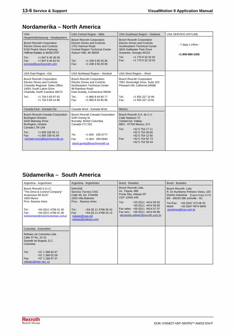
13-6 Service & Support VisualMotion 9 Application Manual
DOK-VISMOT-VM*-09VRS**-AW02-EN-P
Nordamerika – North AmericaUSAHauptniederlassung - Headquarters
Bosch Rexroth CorporationElectric Drives and Controls5150 Prairie Stone ParkwayHoffman Estates, IL 60192-3707
Tel.: +1 847 6 45 36 00Fax: +1 847 6 45 62 [email protected]
USA Central Region - Mitte
Bosch Rexroth CorporationElectric Drives and Controls1701 Harmon RoadCentral Region Technical CenterAuburn Hills, MI 48326
Tel.: +1 248 3 93 33 30Fax: +1 248 3 93 29 06
USA Southeast Region - Südwest
Bosch Rexroth CorporationElectric Drives and ControlsSoutheastern Technical Center3625 Swiftwater Park DriveSuwanee, Georgia 30124
Tel.: +1 770 9 32 32 00Fax: +1 770 9 32 19 03
USA SERVICE-HOTLINE
- 7 days x 24hrs -
+1-800-860-1055
USA East Region –Ost
Bosch Rexroth CorporationElectric Drives and ControlsCharlotte Regional Sales Office14001 South Lakes DriveCharlotte, North Carolina 28273
Tel.: +1 704 5 83 97 62+1 704 5 83 14 86
USA Northeast Region – Nordost
Bosch Rexroth CorporationElectric Drives and ControlsNortheastern Technical Center99 Rainbow RoadEast Granby, Connecticut 06026
Tel.: +1 860 8 44 83 77Fax: +1 860 8 44 85 95
USA West Region – West
Bosch Rexroth Corporation7901 Stoneridge Drive, Suite 220Pleasant Hill, California 94588
Tel.: +1 925 227 10 84Fax: +1 925 227 10 81
Canada East - Kanada Ost
Bosch Rexroth Canada CorporationBurlington Division3426 Mainway DriveBurlington, OntarioCanada L7M 1A8
Tel.: +1 905 335 55 11Fax: +1 905 335-41 84 [email protected]
Canada West - Kanada West
Bosch Rexroth Canada Corporation5345 Goring St.Burnaby, British ColumbiaCanada V7J 1R1
Tel. +1 604 205-5777
Fax +1 604 205-6944
Mexico
Bosch Rexroth S.A. de C.V.Calle Neptuno 72Unidad Ind. VallejoMEX - 07700 Mexico, D.F.
Tel.: +52 5 754 17 11+52 5 754 36 84+52 5 754 12 60
Fax: +52 5 754 50 73+52 5 752 59 43
Südamerika – South AmericaArgentina - Argentinien
Bosch Rexroth S.A.I.C."The Drive & Control Company"Acassusso 48 41/471605 MunroProv. Buenos Aires
Tel.: +54 (0)11 4756 01 40Fax: +54 (0)11 4756 01 [email protected]
Argentina - Argentinien
NAKASEServicio Tecnico CNCCalle 49, No. 5764/661653 Villa BalesterProv. - Buenos Aires
Tel.: +54 (0) 11 4768 36 43Fax: +54 (0) 11 4768 24 13 [email protected] [email protected]
Brazil - Brasilien
Bosch Rexroth Ltda.Av. Tégula, 888Ponte Alta, Atibaia SPCEP 12942-440
Tel.: +55 (0)11 4414 56 92+55 (0)11 4414 56 84
Fax sales: +55 (0)11 4414 57 07Fax serv.: +55 (0)11 4414 56 86 [email protected]
Brazil - Brasilien
Bosch Rexroth Ltda.R. Dr.Humberto Pinheiro Vieira, 100Distrito Industrial [Caixa Postal 1273]BR - 89220-390 Joinville - SC
Tel./Fax: +55 (0)47 473 58 33Mobil: +55 (0)47 9974 6645 [email protected]
Columbia - Kolumbien
Reflutec de Colombia Ltda.Calle 37 No. 22-31Santafé de Bogotá, D.C.Colombia
Tel.: +57 1 368 82 67+57 1 368 02 59
Fax: +57 1 268 97 [email protected]. co


Printed in GermanyDOK-VISMOT-VM*-09VRS**-AW02-EN-PR911292839
Bosch Rexroth AGElectric Drives and ControlsP.O. Box 13 5797803 Lohr, GermanyBgm.-Dr.-Nebel-Str. 297816 Lohr, GermanyPhone +49 93 52-40-50 60Fax +49 93 52-40-49 [email protected]