Revit - University of Michigansven/classes/cadfun05/Revit05.pdf · Assignment 10 Revit CAD...
17
Assignment 10 Revit CAD Fundamentals I Due March 29 Architecture 411 Objectives To learn the basic concepts involved with Building Information Modeling. To become familiar with basic operation of the Revit user interface. To learn techniques for modeling walls and related architectural entities in Revit. Exercise 1. Start Revit and begin a new project. On the third floor of the Art & Architecture Building, you can start Revit by clicking "start->All Programs->Modeling and CAD->Autodesk->Autodesk Revit 6.1-> Autodesk Revit 6.1" from the start button menus. At the Media Union and ITCS Sites labs, the program should be listed somewhere near AutoCAD 2005 in the "start" button menu structure. This will bring up a program window like the one below: In the Project Browser, under "Views (all)", under "Floor Plans", "Level 1" should be highlighted. This allows you to work on the first floor in a plan view. 2. Examine your Snap and Object Snap settings. From the pull-down menus at the top of the screen, select "Settings->Snaps…". You should see a dialog box like the following: 1
-
Upload
hoangduong -
Category
Documents
-
view
217 -
download
2
Transcript of Revit - University of Michigansven/classes/cadfun05/Revit05.pdf · Assignment 10 Revit CAD...

Assignment 10 Revit CAD Fundamentals I Due March 29 Architecture 411
Objectives To learn the basic concepts involved with Building Information Modeling.
To become familiar with basic operation of the Revit user interface.
To learn techniques for modeling walls and related architectural entities in Revit.
Exercise
1. Start Revit and begin a new project. On the third floor of the Art & Architecture Building, you can start Revit by clicking "start->All Programs->Modeling and CAD->Autodesk->Autodesk Revit 6.1-> Autodesk Revit 6.1" from the start button menus. At the Media Union and ITCS Sites labs, the program should be listed somewhere near AutoCAD 2005 in the "start" button menu structure. This will bring up a program window like the one below:
In the Project Browser, under "Views (all)", under "Floor Plans", "Level 1" should be highlighted. This allows you to work on the first floor in a plan view.
2. Examine your Snap and Object Snap settings. From the pull-down menus at the top of the screen, select "Settings->Snaps…". You should see a dialog box like the following:
1
2
“Length dimension snap increments” are similar to the "Snap" setting in AutoCAD, except that the value changes (it gets smaller) the more you zoom in. The dialog box shown above, for instance, indicates that when you are zoomed out a lot, the pointer will snap to 4' increments. If you zoom in more, the pointer will snap to 6" increments. If you zoom in more, the pointer will snap to 1" increments. And if you zoom in farther still, the pointer will snap to ¼" increments.
The "Angular dimension snap increments" affect how you can move the pointer relative to the last point you entered. If you move a short distance, Revit will try to lock you in to movement at a 90 degree angle. If you move a little farther, it will let you move in 45 degree increments. If you move longer distances, it will lock you into 15, 5, or even 1 degree increments.
Object snaps are similar to those found in AutoCAD. The two-letter abbreviations are things that you can type when you are about to enter a point. Each invokes a particular type of object snapping.
For the time being, the default snap settings should work fine. Click "OK".
3. Draw a few walls to learn how the wall tool and the snap settings work. Do not worry if your drawing looks like a mess. For the time being, you are just trying to see how the tool works. You will draw something more meaningful later.
Click "Wall" from the "Basics" tab of the Design Bar. In the drawing area, click to start a wall. Click again to set the other end of the wall. Note that you must click again to begin a new wall; by default, walls do not "chain" together like AutoCAD lines. However, you can alter this behavior by
Assignment 10 Revit CAD Fundamentals I
3
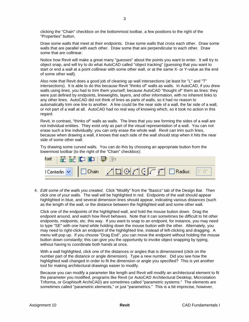
clicking the "Chain" checkbox on the bottommost toolbar, a few positions to the right of the “Properties” button.
Draw some walls that meet at their endpoints. Draw some walls that cross each other. Draw some walls that are parallel with each other. Draw some that are perpendicular to each other. Draw some that are collinear.
Notice how Revit will make a great many "guesses" about the points you want to enter. It will try to object snap, and will try to do what AutoCAD called "object tracking" (guessing that you want to start or end a wall at a point collinear with some other wall, or at the same X- or Y-value as the end of some other wall).
Also note that Revit does a good job of cleaning up wall intersections (at least for "L" and "T" intersections). It is able to do this because Revit "thinks of" walls as walls. In AutoCAD, if you drew walls using lines, you had to trim them yourself, because AutoCAD "thought of" them as lines: they were just defined by endpoints, lineweights, layers, and other information, with no inherent links to any other lines. AutoCAD did not think of lines as parts of walls, so it had no reason to automatically trim one line to another. A line could be the near side of a wall, the far side of a wall, or not part of a wall at all. AutoCAD had no real way of knowing which, so it took no action in this regard.
Revit, in contrast, "thinks of" walls as walls. The lines that you see forming the sides of a wall are not individual entities. They exist only as part of the visual representation of a wall. You can not erase such a line individually; you can only erase the whole wall. Revit can trim such lines, because when drawing a wall, it knows that each side of the wall should stop when it hits the near side of some other wall.
Try drawing some curved walls. You can do this by choosing an appropriate button from the lowermost toolbar (to the right of the “Chain” checkbox):
4. Edit some of the walls you created. Click "Modify" from the "Basics" tab of the Design Bar. Then click one of your walls. The wall will be highlighted in red. Endpoints of the wall should appear highlighted in blue, and several dimension lines should appear, indicating various distances (such as the length of the wall, or the distance between the highlighted wall and some other wall.
Click one of the endpoints of the highlighted wall, and hold the mouse button down. Drag the endpoint around, and watch how Revit behaves. Note that it can sometimes be difficult to hit other endpoints, midpoints, etc. this way. If you want to snap to an endpoint, for instance, you may need to type "SE" with one hand while holding down the mouse button with the other. Alternately, you may need to right-click an endpoint of the highlighted line, instead of left-clicking and dragging. A menu will pop up. If you choose "Drag End", you can move the endpoint without holding the mouse button down constantly; this can give you the opportunity to invoke object snapping by typing, without having to coordinate both hands at once.
With a wall highlighted, click one of the distances or angles that is dimensioned (click on the number part of the distance or angle dimension). Type a new number. Did you see how the highlighted wall changed in order to fit the dimension or angle you specified? This is yet another tool for making architectural drawings easier to modify.
Because you can modify a parameter like length and Revit will modify an architectural element to fit the parameter you modified, programs like Revit (or AutoCAD Architectural Desktop, Microstation Triforma, or Graphisoft ArchiCAD) are sometimes called "parametric systems." The elements are sometimes called "parametric elements," or just "parametrics." This is a bit imprecise, however,
Assignment 10 Revit CAD Fundamentals I

4
since technically even a line is parametric. A line has parameters: start point, end point, layer, color, etc. They just don't correspond very well to the sorts of things that architects want to manipulate, or to the sorts of manipulations architects tend to want to do.
A more accurate description of a program like Revit is "Building Information Modeling” (“BIM”) program. This is because the elements in the program correspond to building elements, and as we shall see, these elements contain information about what they are comprised of, how they are put together, and sometimes, how they perform.
5. Change the type of several of your walls. Select one of your walls by clicking it.
Note what type of wall it is (e.g., "Basic Wall : Generic – 8" ") by looking in the Type Selector in the lowermost toolbar. Click the downward pointing arrow symbol in the type selector to see the complete list of different types of walls available. Try changing the wall type to "Basic Wall : Interior - 4 7/8" Partition (1-hr)". In the plan view, you should see the wall get narrower, because this type of wall is narrower than the default 8" wall.
Now select several other walls. You can use windows and crossing boxes to select several walls at once. As in AutoCAD, if you drag a selection window to the right, it is a selection window that only selects entities that lie completely within the box. If you drag the window to the left as you specify it, it is a crossing box that also selects entities that lie partially within the box.
When you have selected several walls, use the Type Selector to change their type to "Basic Wall : Exterior – Brick on CMU". (This type of wall construction includes a concrete block wall (concrete blocks are known as "Concrete Masonry Units", or "CMUs") faced with standard bricks. When you select this type of wall, you should see the selected walls get wider in the plan, to reflect the fact that a wall of this type is wider than a wall of the previously selected type.
6. Examine the Properties of a wall. Press the "Esc" key to deselect the walls, then click on just one of the brick-on-CMU walls to highlight it. Click the Properties button to the right of the Type Selector. A dialog box like the one below should appear. This dialog box shows properties of the one particular wall that was selected. These properties include the height of the wall, which level of the building it is on ("Base Constraint"), etc.
Assignment 10 Revit CAD Fundamentals I

5
Click the "Edit/New…" button near the top of the dialog box, next to where the type of the wall is listed. This will bring up a new dialog box, like the following:
This dialog box describes the class (or "type") of wall: brick-on-CMU exterior walls. The previous dialog box described a particular instance of this class of wall. While the previous dialog box described the properties of one specific wall, this dialog box describes the properties that all exterior brick-on-CMU walls have in common. Some of these describe how the wall and its components behave. The "Structure" field refers to a description of what components comprise a brick-on-CMU exterior wall.
Click the long, narrow "Edit…" button next to "Structure". Yet another dialog box appears:
Assignment 10 Revit CAD Fundamentals I
6
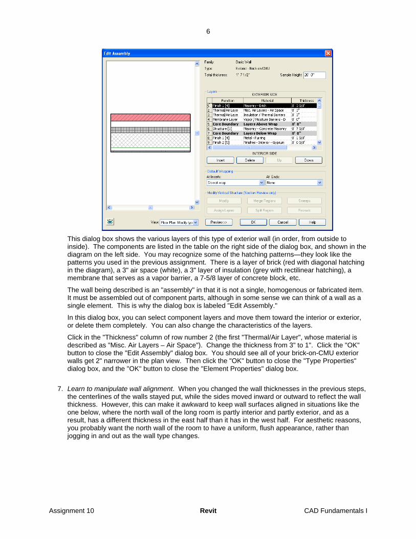
This dialog box shows the various layers of this type of exterior wall (in order, from outside to inside). The components are listed in the table on the right side of the dialog box, and shown in the diagram on the left side. You may recognize some of the hatching patterns—they look like the patterns you used in the previous assignment. There is a layer of brick (red with diagonal hatching in the diagram), a 3" air space (white), a 3" layer of insulation (grey with rectilinear hatching), a membrane that serves as a vapor barrier, a 7-5/8 layer of concrete block, etc.
The wall being described is an "assembly" in that it is not a single, homogenous or fabricated item. It must be assembled out of component parts, although in some sense we can think of a wall as a single element. This is why the dialog box is labeled "Edit Assembly."
In this dialog box, you can select component layers and move them toward the interior or exterior, or delete them completely. You can also change the characteristics of the layers.
Click in the "Thickness" column of row number 2 (the first "Thermal/Air Layer", whose material is described as "Misc. Air Layers – Air Space"). Change the thickness from 3" to 1". Click the "OK" button to close the "Edit Assembly" dialog box. You should see all of your brick-on-CMU exterior walls get 2" narrower in the plan view. Then click the "OK" button to close the "Type Properties" dialog box, and the "OK" button to close the "Element Properties" dialog box.
7. Learn to manipulate wall alignment. When you changed the wall thicknesses in the previous steps, the centerlines of the walls stayed put, while the sides moved inward or outward to reflect the wall thickness. However, this can make it awkward to keep wall surfaces aligned in situations like the one below, where the north wall of the long room is partly interior and partly exterior, and as a result, has a different thickness in the east half than it has in the west half. For aesthetic reasons, you probably want the north wall of the room to have a uniform, flush appearance, rather than jogging in and out as the wall type changes.
Assignment 10 Revit CAD Fundamentals I

7
Draw a wall and assign a type to it. Using a different wall type, draw a second wall which is collinear to it at one end, like shown below. (Make sure that you use a different wall type—otherwise, Revit will recognize the segments as a single wall, and will treat it accordingly.)
Select both walls, and click the Properties button. In the "Element Properties" dialog box, find the "Location Line" parameter, and click the corresponding value, which should be "Wall Centerline". A small down-arrow should appear; click it, and select "Finish Face: Interior". Then click "OK" to close the dialog box.
Now click on the two walls, one at a time. When you highlight them, notice where the blue endpoints appear. The endpoints should no longer appear along the centerline of the wall, they should appear along the upper or lower edge. What you have done is change how the wall "sits on" the line defined by the endpoints—where the wall is located, relative to the defining line.
It is possible that one of your walls will now have its endpoints located along the upper surface of the wall, while the other wall has endpoints along the lower surface of the wall. This is not a significant problem; Revit has a simple way to switch the sides of a wall.
When you highlight a single wall, you may notice a pair of blue arrows pointing in opposite directions, along one side of the wall:
If you click these blue arrows, it will reverse the sides of the wall. What had previously been considered to be the "exterior surface" will be switched with what had previously been considered the "interior surface". You previously told Revit to position the endpoints of the walls along the interior surfaces; if those interior surfaces are not both on the same side, you can use the blue arrows to switch the sides of one of them.
Assignment 10 Revit CAD Fundamentals I

8
Once the endpoints are on the same side of both of your walls, drag the endpoints of one line to make them line up smoothly with the endpoints of the other line, as seen below:
Note: this works best if your two collinear walls are separated from all other walls, so that no other walls intersect the two collinear ones. As discussed below in step 14, Revit sometimes has difficulty aligning walls as told if there are complex wall intersections in the vicinity.
8. Practice zooming in and out. As in AutoCAD, you can zoom in and out by using the middle wheel of the mouse. If you do not have a mouse with a middle wheel, you can zoom in and out by going to "View->Zoom" in the pull-down menus, and choosing one of the zoom commands from the menu that pops up to the side. These menus also show various two-letter command abbreviations that can be used to zoom.
9. Start a new Revit project. Choose “File->New…” from the menus. A dialog box will be displayed:
You should just click “OK to select the default template file.
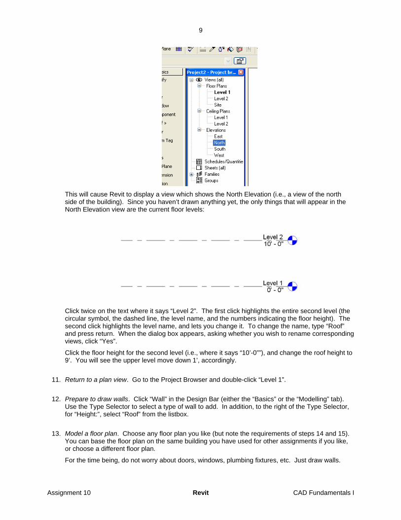
10. Set up the levels for a single-story project. Start by looking at the default levels in elevation. To do this, go to the project browser, expand “Views (all)”, and expand “Elevations”. (“Expand” means to click the plus sign beside an entry, so that you see the sub-entries.) Double-click “North”.
Assignment 10 Revit CAD Fundamentals I
9
This will cause Revit to display a view which shows the North Elevation (i.e., a view of the north side of the building). Since you haven’t drawn anything yet, the only things that will appear in the North Elevation view are the current floor levels:
Click twice on the text where it says “Level 2”. The first click highlights the entire second level (the circular symbol, the dashed line, the level name, and the numbers indicating the floor height). The second click highlights the level name, and lets you change it. To change the name, type “Roof” and press return. When the dialog box appears, asking whether you wish to rename corresponding views, click “Yes”.
Click the floor height for the second level (i.e., where it says “10’-0””), and change the roof height to 9’. You will see the upper level move down 1’, accordingly.
11. Return to a plan view. Go to the Project Browser and double-click “Level 1”.
12. Prepare to draw walls. Click “Wall” in the Design Bar (either the “Basics” or the “Modelling” tab). Use the Type Selector to select a type of wall to add. In addition, to the right of the Type Selector, for “Height:”, select “Roof” from the listbox.
13. Model a floor plan. Choose any floor plan you like (but note the requirements of steps 14 and 15). You can base the floor plan on the same building you have used for other assignments if you like, or choose a different floor plan.
For the time being, do not worry about doors, windows, plumbing fixtures, etc. Just draw walls.
Assignment 10 Revit CAD Fundamentals I
10
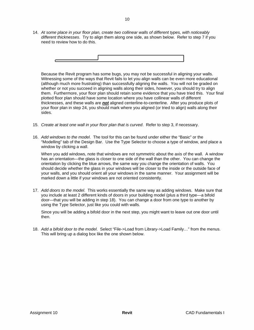
14. At some place in your floor plan, create two collinear walls of different types, with noticeably different thicknesses. Try to align them along one side, as shown below. Refer to step 7 if you need to review how to do this.
Because the Revit program has some bugs, you may not be successful in aligning your walls. Witnessing some of the ways that Revit fails to let you align walls can be even more educational (although much more frustrating) than successfully aligning the walls. You will not be graded on whether or not you succeed in aligning walls along their sides, however, you should try to align them. Furthermore, your floor plan should retain some evidence that you have tried this. Your final plotted floor plan should have some location where you have collinear walls of different thicknesses, and these walls are not aligned centerline-to-centerline. After you produce plots of your floor plan in step 24, you should mark where you aligned (or tried to align) walls along their sides.
15. Create at least one wall in your floor plan that is curved. Refer to step 3, if necessary.
16. Add windows to the model. The tool for this can be found under either the “Basic” or the “Modelling” tab of the Design Bar. Use the Type Selector to choose a type of window, and place a window by clicking a wall.
When you add windows, note that windows are not symmetric about the axis of the wall. A window has an orientation—the glass is closer to one side of the wall than the other. You can change the orientation by clicking the blue arrows, the same way you change the orientation of walls. You should decide whether the glass in your windows will be closer to the inside or the outside face of your walls, and you should orient all your windows in the same manner. Your assignment will be marked down a little if your windows are not oriented consistently.
17. Add doors to the model. This works essentially the same way as adding windows. Make sure that you include at least 2 different kinds of doors in your building model (plus a third type—a bifold door—that you will be adding in step 18). You can change a door from one type to another by using the Type Selector, just like you could with walls.
Since you will be adding a bifold door in the next step, you might want to leave out one door until then.
18. Add a bifold door to the model. Select “File->Load from Library->Load Family…” from the menus. This will bring up a dialog box like the one shown below.
Assignment 10 Revit CAD Fundamentals I

11
Double-click the “Doors” directory, and the dialog box should display a list of .rfa files. Click “Bifold-4 Panel.rfa” from the list, and click “Open”.
Once you load the .rfa file for the bifold door, you can click a wall to add an instance of the door to your model. Counting this bifold door, you should have a total of at least 3 types of doors in your model.
By default, only a few classes (“families”) of building products are loaded into memory when the Revit program runs. Many more are defined in data files that come with Revit, which can be explicitly loaded. Still more families are available via the web library (note the “Web Library” button in the “Open” dialog box). Families are available for doors, windows, lights, structural members, and other building products. Each definition includes various attributes (e.g., “height”) that describe the thing being defined, values for some of those attributes (e.g., “72””), a 3D model of the thing, a 2D representation to be used for elevation views of the thing, and a 2D representation to be used for plan views of the thing.
Revit also comes with template files that can be used to define additional families. The template files describe some of the functionality for building components—like the fact that doors and windows can not be freestanding: they have to be embedded in a wall, and will move when the wall moves. Advanced users of Revit can use these templates to define additional building products, but this is far beyond the scope of this course.
You may wish use some of the available libraries of families to embellish your model later. It is all right for you to use these libraries. Since defining building products is a fairly difficult task, it will be assumed that all doors, furniture, lights, etc. in your model come from Revit libraries, rather than being your own creation. However, if you use files that come from any source other than AutoDesk, you should document the source with a note when you hand in your assignment.
19. Produce a door schedule. When architects produce construction drawings for a project, the drawings include tables that list the doors and windows to be installed in the building. These tables are called “door and window schedules.”
Right-click the Design Bar and check the “View” tab. When the View tab and its contents are displayed in the Design Bar, click “Schedule/Quantities”. A dialog box will appear:
Assignment 10 Revit CAD Fundamentals I
12
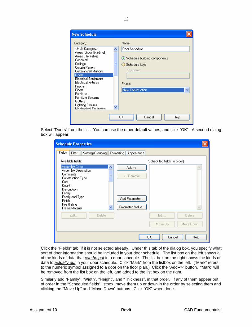
Select “Doors” from the list. You can use the other default values, and click “OK”. A second dialog box will appear:
Click the “Fields” tab, if it is not selected already. Under this tab of the dialog box, you specify what sort of door information should be included in your door schedule. The list box on the left shows all of the kinds of data that can be put in a door schedule. The list box on the right shows the kinds of data to actually put in your door schedule. Click “Mark” from the listbox on the left. (“Mark” refers to the numeric symbol assigned to a door on the floor plan.) Click the “Add-->” button. “Mark” will be removed from the list box on the left, and added to the list box on the right.
Similarly add “Family”, “Width”, “Height”, and “Thickness”, in that order. If any of them appear out of order in the “Scheduled fields” listbox, move them up or down in the order by selecting them and clicking the “Move Up” and “Move Down” buttons. Click “OK” when done.
Assignment 10 Revit CAD Fundamentals I

13
The dialog box will disappear, and a door schedule will be displayed:
The lines between columns can be dragged left or right, allowing you to change the column width.
20. Go back to your floor plan and add a door. You can switch to the floor plan by double-clicking “Level 1” in the project browser. Add a new door somewhere in the floor plan.
21. Go back to the door schedule.
Note that the door schedule already includes the new door. This is because the door schedule is not extracted from your building model; instead, Revit considers it to be just another view of your building model.
Each view of the building model contains only certain information. For instance, a plan of the first floor contains only information about entities associated with the first floor. Most of the information shown on a plan of the first floor is graphical in nature, for instance, lines outlining a wall, or a symbol for a door. But the lines themselves are not the wall. The symbol is not the door. The wall is an instance of a wall object, and is stored in the building database. The wall has many parameters, including, but not limited to, its start point, its end point, a list of material layers and their thicknesses, what level of the building the wall is on, and so forth.
Similarly, a door is an instance of a door object, and is stored in the building database. It too has its own particular attributes. Some of these attributes (like the graphical symbol for the door) can be displayed in a floor plan view. Others, like “Family”, can be displayed in a schedule view. And some, like “Mark” are shown in both views. This allows a contractor to look at the floor plan, find the number for the door, then look up the door in the door schedule to see which model of door to put at that location.
Neither view is produced from the other. Rather, both views are just different views of the building model/database.
22. Export the door schedule. Choose “File->Export->Schedule…” from the menus. A large dialog box will appear. Specify a file name and click “Save”. A smaller dialog box will then appear:
Assignment 10 Revit CAD Fundamentals I

14
Use the settings shown above, which will probably be the default settings. Click “OK”.
23. Open your exported file using a text editor or word processor. If the columns do not line up neatly, try changing the font to a fixed-width font like courier, or try setting tab stops. You should get the columns to line up neatly.
24. Print your exported door schedule. Use the “File->Print…” command from the text editor/word processor. Save your file if, if you made any changes to it. Exit the text editor/word processor.
25. Embellishment/extra work. Explore other commands in Revit. Revit is a large, complex program, and this tutorial hardly covers the most introductory concepts and commands. There are many other things Revit does that you can explore. Revit has a help system and a large collection of tutorials that may help you explore other functions.
You can try dimensioning in Revit. In many ways, it is easier in Revit than in AutoCAD, because Revit knows what kinds of objects are depicted in the plan, and it has some idea of which sorts of objects architects usually dimension to, and which key points on those objects an extension line should extend from.
If you are willing to experiment, you might want to add an additional floor to your building model, or try having Revit generate a roof based on the building footprint. However, it may take some effort and experimentation to be successful.
You can try creating a building section. This is actually almost trivial in Revit; it’s basically a matter of adding a section symbol to show where the cut is. Revit cuts the model and computes what to draw in the building section essentially automatically.
You can add “components” to your model. Many components are available if you load the proper .rfa files as described in step 18. Note, however, that while adding components is relatively simple and fast, and it will only improve your score a little.
You can try using commands in the “Site” menu or under the “site” tab of the design bar to create contour lines and a site model.
You can try using the “View” tab of the Design Bar to create sheets with title blocks and viewports showing views of your building model. If you do this, you will need to set your plot settings appropriately in order to plot the sheet instead of plotting what is on the display
Assignment 10 Revit CAD Fundamentals I

15
Operations that are effort-intensive and operations that require you to figure out something difficult will count as more embellishment than quick, simple operations.
Complexity of your floor plan will also count towards embellishment.
26. Print your floor plan. First, zoom/scroll so that you fill as much of the screen as possible with your floor plan, but still have your entire floor plan on the screen. It is not necessary to include the four “arrows” that surround your model. (In case you are wondering, the 4 “arrows” are symbols indicating where elevation views are taken from. If you delete one of the “arrows,” you will delete an elevation view. If you double-click an arrow, you will display that view on the screen.)
Prior to printing, it is also a good idea to change the proportions of your graphics window, so that the window has approximately the same proportions as the paper upon which you intend to plot. This way, when Revit fits the contents of the graphics window to the paper, it may be able to generate a larger plot, with less white space padding the sides.
Choose “File->Print…” from the menus. This will bring up a dialog box:
For “Print range”, select “Visible portion of current window”. Then click “Setup…”. This will bring up another dialog box:
Assignment 10 Revit CAD Fundamentals I

16
Make sure that “Center” and “Fit to page” are chosen. Choose either “Landscape” or “Portrait,” whichever better fits the format of your floor plan. Click “OK” when done.
When you return to the “Print” dialog box, click “Preview” to make sure that your floor plan will be shown properly. Note however, that the Print Preview function in Revit does not always depict the print accurately—i.e., it sometimes “lies.” Sometimes you need to actually print in order to see what the print will look like. When you are ready, click “OK” in the “Print” dialog box.
27. Go to a 3D view of your building model. Go to the uppermost toolbar below the pull-down menus, and click on the icon that looks like a small house:
This should bring up a 3D view of your building model. It should also add a 3D view (called “{3D}”, under “3D Views”) to the Project Browser.
If you don’t like the angle from which the model is viewed, you can change it. To do this, click the icon that looks like an eye with three arrows coming from it. This will cause a small dialog box to appear:
Assignment 10 Revit CAD Fundamentals I
17
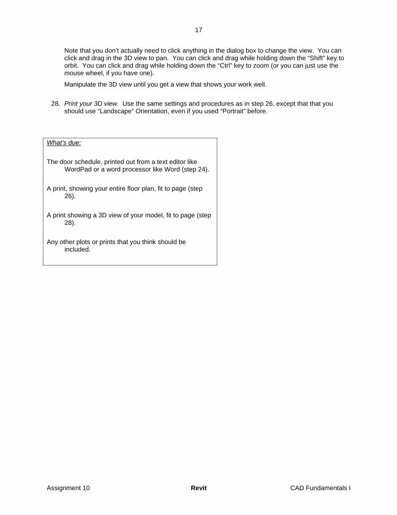
Note that you don’t actually need to click anything in the dialog box to change the view. You can click and drag in the 3D view to pan. You can click and drag while holding down the “Shift” key to orbit. You can click and drag while holding down the “Ctrl” key to zoom (or you can just use the mouse wheel, if you have one).
Manipulate the 3D view until you get a view that shows your work well.
28. Print your 3D view. Use the same settings and procedures as in step 26, except that that you should use “Landscape” Orientation, even if you used “Portrait” before.
What’s due:
The door schedule, printed out from a text editor like WordPad or a word processor like Word (step 24).
A print, showing your entire floor plan, fit to page (step 26).
A print showing a 3D view of your model, fit to page (step 28).
Any other plots or prints that you think should be included.
Assignment 10 Revit CAD Fundamentals I