
REVIT MODEL CONTENT STYLE GUIDE - … · Architecture, Revit® MEP, and Revit® Structure. Model...
67
REVIT MODEL CONTENT STYLE GUIDE December 2009 Version 2.1
Transcript of REVIT MODEL CONTENT STYLE GUIDE - … · Architecture, Revit® MEP, and Revit® Structure. Model...
REVIT MODEL CONTENT STYLE GUIDE
December 2009
Version 2.1
Copyright© 2009 Autodesk, Inc. All Rights Reserved
This publication, or parts thereof, may not be reproduced in any form, by any method, for any purpose. AUTODESK, INC., MAKES NO WARRANTY, EITHER EXPRESS OR IMPLIED, INCLUDING BUT NOT LIMITED TO ANY IMPLIED WARRANTIES OF MERCHANTABILITY OR FITNESS FOR A PARTICULAR PURPOSE REGARDING THESE MATERIALS, AND MAKES SUCH MATERIALS AVAILABLE SOLELY ON AN "AS-IS" BASIS. IN NO EVENT SHALL AUTODESK, INC., BE LIABLE TO ANYONE FOR SPECIAL, COLLATERAL, INCIDENTAL, OR CONSEQUENTIAL DAMAGES IN CONNECTION WITH OR ARISING OUT OF PURCHASE OR USE OF THESE MATERIALS. THE SOLE AND EXCLUSIVE LIABILITY TO AUTODESK, INC., REGARDLESS OF THE FORM OF ACTION, SHALL NOT EXCEED THE PURCHASE PRICE OF THE MATERIALS DESCRIBED HEREIN.
Autodesk, Inc., reserves the right to revise and improve its products as it sees fit. This publication describes the state of the product at the time of publication, and may not reflect the product at all times in the future.
Autodesk Trademarks
The following are registered trademarks of Autodesk, Inc., in the USA and/or other countries: 3D Props, 3D Studio, 3D Studio MAX, 3D Studio VIZ, 3DSurfer, 3ds max, ActiveShapes, ActiveShapes (logo), Actrix, ADI, AEC Authority (logo), AEC-X, Animator Pro, Animator Studio, ATC, AUGI, AutoCAD, AutoCAD LT, AutoCAD Map, Autodesk, Autodesk Envision, Autodesk Inventor, Autodesk (logo), Autodesk Map, Autodesk MapGuide, Autodesk Streamline, Autodesk University (logo), Autodesk View, Autodesk WalkThrough, Autodesk World, AutoLISP, AutoSketch, backdraft, Biped, bringing information down to earth, Buzzsaw, CAD Overlay, Character Studio, Cinepak, Cinepak (logo), cleaner, Codec Central, combustion, Design Your World, Design Your World (logo), EditDV, Education by Design, gmax, Heidi, HOOPS, Hyperwire, i-drop, Inside Track, IntroDV, Kinetix, lustre, MaterialSpec, Mechanical Desktop, NAAUG, ObjectARX, Physique, Planix, Powered with Autodesk Technology (logo), ProjectPoint, RadioRay, Reactor, Revit, Softdesk, Texture Universe, The AEC Authority, The Auto Architect, VISION*, Visual, Visual Construction, Visual Drainage, Visual Hydro, Visual Landscape, Visual Roads, Visual Survey, Visual Toolbox, Visual Tugboat, Visual LISP, Volo, WHIP!, and WHIP! (logo).
The following are trademarks of Autodesk, Inc., in the USA and/or other countries: AutoCAD Learning Assistance, AutoCAD LT Learning Assistance, AutoCAD Simulator, AutoCAD SQL Extension, AutoCAD SQL Interface, AutoSnap, AutoTrack, Built with ObjectARX (logo), burn, Buzzsaw.com, CAiCE, Cinestream, Civil 3D, cleaner central, ClearScale, Colour Warper, Content Explorer, Dancing Baby (image), DesignCenter, Design Doctor, Designer's Toolkit, DesignKids, DesignProf, DesignServer, Design Web Format, DWF, DWFit, DWG Linking, DXF, Extending the Design Team, GDX Driver, gmax (logo), gmax ready (logo),Heads-up Design, jobnet, ObjectDBX, onscreen onair online, Plans & Specs, Plasma, PolarSnap, Productstream, Real-time Roto, Render Queue, Visual Bridge, Visual Syllabus, and Where Design Connects.
Autodesk Canada Co. Trademarks The following are registered trademarks of Autodesk Canada Inc. in the USA and/or Canada, and/or other countries: discreet, fire, flame, flint, flint RT, frost, glass, inferno, MountStone, riot, river, smoke, sparks, stone, stream, vapour, wire.
The following are trademarks of Autodesk Canada Inc., in the USA, Canada, and/or other countries: backburner, Multi-Master Editing.
Third Party Trademarks All other brand names, product names or trademarks belong to their respective holders.
Third Party Software Program Credits ACIS Copyright© 1989-2001 Spatial Corp. Portions Copyright© 2002 Autodesk, Inc.
Copyright© 1997 Microsoft Corporation. All rights reserved.
Flash ® is a registered trademark of Macromedia, Inc. in the United States and/or other countries.
International CorrectSpell™ Spelling Correction System© 1995 by Lernout & Hauspie Speech Products, N.V. All rights reserved.
InstallShield™ 3.0. Copyright© 1997 InstallShield Software Corporation. All rights reserved.
PANTONE® Colors displayed in the software application or in the user documentation may not match PANTONE-identified standards. Consult current PANTONE Color Publications for accurate color.
PANTONE® and other Pantone, Inc. trademarks are the property of Pantone, Inc.© Pantone, Inc., 2002
Pantone, Inc. is the copyright owner of color data and/or software which are licensed to Autodesk, Inc., to distribute for use only in combination with certain Autodesk software products. PANTONE Color Data and/ or Software shall not be copied onto another disk or into memory unless as part of the execution of this Autodesk software product.
Portions Copyright© 1991-1996 Arthur D. Applegate. All rights reserved.
Portions of this software are based on the work of the Independent JPEG Group.
RAL DESIGN© RAL, Sankt Augustin, 2002
RAL CLASSIC© RAL, Sankt Augustin, 2002
RMCSG — 2 Version 2.1
Representation of the RAL Colors is done with the approval of RAL Deutsches Institut für Gütesicherung und Kennzeichnung e.V. (RAL German Institute for Quality Assurance and Certification, re. Assoc.), D-53757 Sankt Augustin.
Typefaces from the Bitstream® typeface library copyright 1992.
Typefaces from Payne Loving Trust© 1996. All rights reserved.
AutoCAD 2006 is produced under a license of data derived from DIC Color Guide® from Dainippon Ink and Chemicals, Inc. Copyright © Dainippon Ink and Chemicals, Inc. All rights reserved. DIC Color Guide computer color simulations used in this product may not exactly match DIC Color Guide, DIC color Guide Part 2 identified solid color standards. Use current DIC Color Guide Manuals for exact color reference. DIC and DIC Color Guide are registered trademarks of Dainippon Ink and Chemicals, Inc.
Printed manual and help produced with Idiom WorldServer™ .
WindowBlinds: DirectSkin™ OCX © Stardock®
AnswerWorks 4.0 © ; 1997-2003 WexTech Systems, Inc. Portions of this software © Vantage-Knexys. All rights reserved.
The Director General of the Geographic Survey Institute has issued the approval for the coordinates exchange numbered TKY2JGD for Japan Geodetic Datum 2000, also known as technical information No H1-N0.2 of the Geographic Survey Institute, to be installed and used within this software product (Approval No.: 646 issued by GSI, April 8, 2002).
Portions of this computer program are copyright © 1995-1999 LizardTech, Inc. All rights reserved. MrSID is protected by U.S. Patent No. 5,710,835. Foreign Patents Pending.
Portions of this computer program are Copyright © ; 2000 Earth Resource Mapping, Inc.
OSTN97 © Crown Copyright 1997. All rights reserved.
OSTN02 © Crown copyright 2002. All rights reserved.
OSGM02 © Crown copyright 2002, © Ordnance Survey Ireland, 2002.
FME Objects Engine © 2005 SAFE Software. All rights reserved.
GOVERNMENT USE Use, duplication, or disclosure by the U.S. Government is subject to restrictions as set forth in FAR 12.212 (Commercial Computer Software-Restricted Rights) and DFAR 227.7202 (Rights in Technical Data and Computer Software), as applicable.
Version 2.1 RMCSG — 3
CONTENTS Feedback on the Guide 7
Audience 7
Definition: Quality Revit Content 7
Contents 8
Supplementary Files 8
Additional Files 9
Section 1: Planning Revit Model Content 10
Recommended Revit Release and Discipline for Content Creation 10
1.1 Determining Design Intent 11
Determining the Template to Use 11
Family Representations 12
1.2 Balancing Performance and Design Complexity 16
Design Intent vs. Performance 16
Recommended Family File Sizes 18
Level of Detail 19
Element Visibility 20
Areas to Avoid for Optimum Performance 20 Examples of Families with Appropriate and complex Levels of Detail 21
Considerations for Nesting Family Content 22 Nesting Recommendations: 22
1.3 Autodesk Exchange Format (.ADSK) 23
AEC Exchange Environment 23
Creating Intelligent Connectors 23
Simplifying the Geometric Representation 24
Publishing to the .ADSK format 24
reading .ADSK files 25
Importing into Revit Families 25
Limitations 25
1.4 Using Imported Content 26
RMCSG — 4 Version 2.1
Supported Content 26
Limitations 26
1.5 Planning a Revit Model Family 27
Section 2: Model Content Creation Standards 28
2.1 Workflow for Model Content Creation 29
Prototyping 30
2.2 Family Units 30
2.3 Family Naming Conventions 31
2.4 Type Naming Conventions 33
2.5 Category and Subcategory Standards and Usage 35
Adding Subcategories To Model Families 35
Subcategory Naming Conventions 36
2.6 Autodesk Approved Parameter Usage 37
Adding Manufacturer Data to Families 38
CSI OmniClass Table 49 38
CSI Classification Codes 39 Assigning the MasterFormat and UniFormat Classification in Revit 39 Assigning the OmniClass classification in Revit (Revit 2010 and later) 40
2.7 Parameter Naming Conventions 41
2.8 Material Naming Conventions 44
Guidelines 44 Format For Individual Finish Materials (Stored Inside Projects) 44 Format For Individual Finish Materials Using an External Image File 45 Format For Individual Materials Images (Stored OutSide of Revit) 45
2.9 Preview Image Standards 46
Creating Autodesk Standard Family Preview Images 47
2.10 Type Catalog Standards and Usage 52
Type Catalog Standards 52
2.11 Material Application in Model Families 54
Option 1 – Apply Materials with the Material Parameter 54
Version 2.1 RMCSG — 5
Option 2 – Apply Materials to Family Geometry by Category and Subcategory 55
Option 3 – Apply Materials with Custom Instance or Type Material Parameters 55
Example: Assigning Materials to a Table Family 56
2.12 Best Practices for Adding Connectors in Revit MEP Families 58
Adding a Connector 58 System Types 59 Connector Direction 60 Primary Connector 60 Linking Connector 61 Connector Mapping 62 Connector Descriptions 63
Section 3: Testing Guidelines 64
3.1 General Family Testing Guidelines 65
Family Editor Testing Criteria 65
Project Testing Criteria for Revit Architecture 66
3.2 Family‐Specific Testing Guidelines 67
RMCSG — 6 Version 2.1
INTRODUCTION The purpose of this guide is to define Autodesk guidelines and standards for model content creation in Revit® Architecture, Revit® MEP, and Revit® Structure. Model content refers to the two‐dimensional and three‐dimensional standard component families that are used to create elements that represent manufactured content (for example, windows, furnaces, heat pumps, and structural steel members).
By following the guidelines and standards in this guide, content creators will ensure the portability and performance of their content, and fulfill the necessary distribution requirements for the Autodesk® Seek web service. The Autodesk Seek web service requires:
• the uniform display of products offered by a single manufacturer
• complete, consistent, and accurate presentation of product data across manufacturers
• the full use of Autodesk Seek search capabilities
FEEDBACK ON THE GUIDE
Please send your comments on the Revit Model Style Guide and supporting documentation to:
We can’t respond to comments individually, but feedback will be considered in future versions of the Revit Model Content Style Guide.
AUDIENCE
This guide is intended for manufacturers, content service organizations, and other content creators who have advanced knowledge of both Revit software and Revit model content creation.
DEFINITION: QUALITY REVIT CONTENT
Quality Revit content balances performance with design accuracy and required levels of detail. Quality content is easy to use because it functions reliably in a range of projects and project phases, while delivering manufactured content in a format appropriate for architecture and engineering documentation deliverables.
Quality Revit content is created with the following considerations:
• Design intent – the author has considered how the family will be used in a project. • Appropriate level of detail designed • Adequate number of types created • Flexible use of parameters
• Accuracy – complete, consistent presentation of product data. • Standards – adheres to industry and Autodesk standards.
• Naming conventions • Graphic guidelines
Version 2.1 RMCSG — 7
• Parameter usage • Performance – content designed to reduce the performance impact of the family on a project. • Testing – thorough testing of the family parameters and types independently and in a project
environment.
CONTENTS
Section 1: Planning Revit Model Content
• Explains how design complexity in families can affect project performance and offers guidelines for reducing performance impact
• Details the recommended use and limitations of content created with other CAD software
• Provides best practices for planning model content
Section 2: Model Content Creation Standards
• Describes best practices for model content creation
• Contains Autodesk standards for units, naming conventions, subcategories, parameters, preview images, and type catalogs
Section 3: Testing Guidelines
• Contains general and family‐specific testing guidelines for model content families.
Not included in this guide:
• Detailed family creation instructions
• Standards for annotation or system family creation
• Category‐specific guidelines for family creation
• In‐depth best practices for family creation
SUPPLEMENTARY FILES
The following documents and files are referenced for use with this guide and are included in the download package.
• Revit Master Parameter List .xls ‐ includes Autodesk‐approved Revit master shared parameters
• Revit Master Shared Parameter File.txt ‐ includes Autodesk‐approved shared parameters to use in your projects
• Revit Master Subcategory List.xls – includes Autodesk‐approved Revit subcategories
• Revit Master Part Type List.xls – includes Autodesk‐approved Revit part types
• Revit Model Content Sample Files – includes sample Revit model content and images
• Category‐specific Model Content Guides – includes creation guidelines for specific content
• Sharing Revit Content on Autodesk Seek – includes distribution requirements for the Autodesk Seek web service.
RMCSG — 8 Version 2.1
ADDITIONAL FILES
The following resources are available for working with both Revit model content and Autodesk Seek.
AUTODESK METADATA STYLE GUIDE AND PRODUCT WORKBOOK
The Autodesk Metadata Style Guide defines styles and formatting rules that manufacturers, content service organizations, and content specialists must abide by so that the content that they produce can be loaded into the Autodesk Seek staging environment.
Download at: http://seek.autodesk.com/participate.htm.
DOCUMENTATION
For more information on Revit family content creation, see the following reference manuals and tutorials:
• Revit® Architecture Families Guide Download at www.autodesk.com/revitarchitecture‐documentation.
• Revit Architecture, Revit® MEP, and Revit® Structure Tutorials Download at: www.autodesk.com/revitarchitecture‐documentation www.autodesk.com/revitmep‐documentation www.autodesk.com/revitstructure‐documentation
DISCUSSION GROUPS
• AUGI (Autodesk User Group International) Access at www.augi.com.
• Autodesk Seek Discussion Group Access at www.autodesk.com/contentsearch‐discussion.
Version 2.1 RMCSG — 9
SECTION 1: PLANNING REVIT MODEL CONTENT In order to ensure Revit model content is developed efficiently and to Autodesk standards, content creators should follow Autodesk‐approved best practices when creating Revit families.
By following the guidelines in this section, you can:
• create Revit family content easily and with fewer errors
• ensure consistency and stability of Revit family content
• create content suitable for delivery on Autodesk Seek
RECOMMENDED REVIT RELEASE AND DISCIPLINE FOR CONTENT CREATION
Note: All sample family and project files were created based on the Revit Platform 2009 release; therefore, they can’t be opened in earlier versions of Revit.
RECOMMENDATION: To ensure that content is available to the largest number of end users, create the content using Autodesk Revit 2009. Content created in release 2009 can also be used in later versions of Revit. If the content requires functionality available in a later release, then create the content in that release of Revit.
Use the Revit product (Revit Architecture, Revit MEP, or Revit Structure) that is appropriate for the content you are creating, for example, for a Door family, use Revit Architecture, for an Air Handling Unit, use Revit MEP. If the content crosses disciplines, for example, a lighting fixture or plumbing fixture, use the product that has the most requirements, in this case Revit MEP.
RMCSG — 10 Version 2.1
1.1 DETERMINING DESIGN INTENT
When creating a Revit family, the intended use of the family in a project environment determines the extent to which it is designed. You can design all families to include a number of representations for use in different project views and project phases.
The type and size of the project that a family is intended for use in is a critical point to consider when deciding what representations should be included in the family and what level of detail each representation should have. The more detailed a family is, the larger its file size will be. The larger the file size, the slower the performance, loading, and regeneration time of the family will be. When considering the design intent of a family, use the following guidelines:
• For larger commercial or institutional projects, in which hundreds of elements may be created with a single family, design the family to be as small as possible to minimize project size and performance impact.
• For smaller residential projects, where elements created with a single family are not used ubiquitously and where the overall project size is smaller, design the family to include more detail.
The next topic, Balancing Performance and Complexity, addresses the issue of family size and complexity in more detail.
DETERMINING THE TEMPLATE TO USE
For objects typically hosted by other components, such as a window or light fixture, start with a host‐based template. For example, for a window or door, use a wall‐based template, such as Window.rft or Door.rft. How the family is hosted (or what it does or does not attach to) determines which template should be used to create the family. In general, the choice of a template is driven by the host of the object, with the following exceptions:
• Floor‐based objects typically use a level‐based template unless they are required to cut the floor. For example, Furniture objects are created with a level‐based template.
• For objects that are designed to be used in more than one discipline, such as plumbing or lighting fixtures, use a host‐based template that allows the greatest flexibility for all disciplines. For example, a lighting fixture used exclusively in an architectural discipline could be created with a ceiling or wall‐based template, but for an engineering environment, a face‐based template is required for the model linking workflow. Therefore, for a lighting fixture that will be used in both disciplines, use a face‐based template.
Version 2.1 RMCSG — 11
FAMILY REPRESENTATIONS
Depending on the intended use of a family, it may contain the following representations:
• Schematic (generic content; typically not manufacturer specific; may include multiple levels of detail)
• Design development (manufacturer‐specific content; typically Coarse level of detail)
• Construction document (manufacturer‐specific content; typically Medium level of detail)
• High quality rendering (manufacturer‐specific content; typically Fine level of detail)
Depending on the use case for the content, the 3 manufacturer‐specific representations (Design development, Construction document, and High quality rendering) may be developed in 1 or 2 family files. For example, one family file may contain the Design development and Construction documentation representations of the content and a second file may contain the high quality rendering representation. Typically MEP content does not include a high quality rendering, so for this type of content one family file may be created containing the Design development and Construction documentation representations.
SCHEMATIC
Schematic representations are created from two‐dimensional line work and represent the family object in its most basic appearance. They can be considered “placeholders” for elements that will be included in more detailed design drawings. Schematic representations do not usually display materials.
RMCSG — 12 Version 2.1
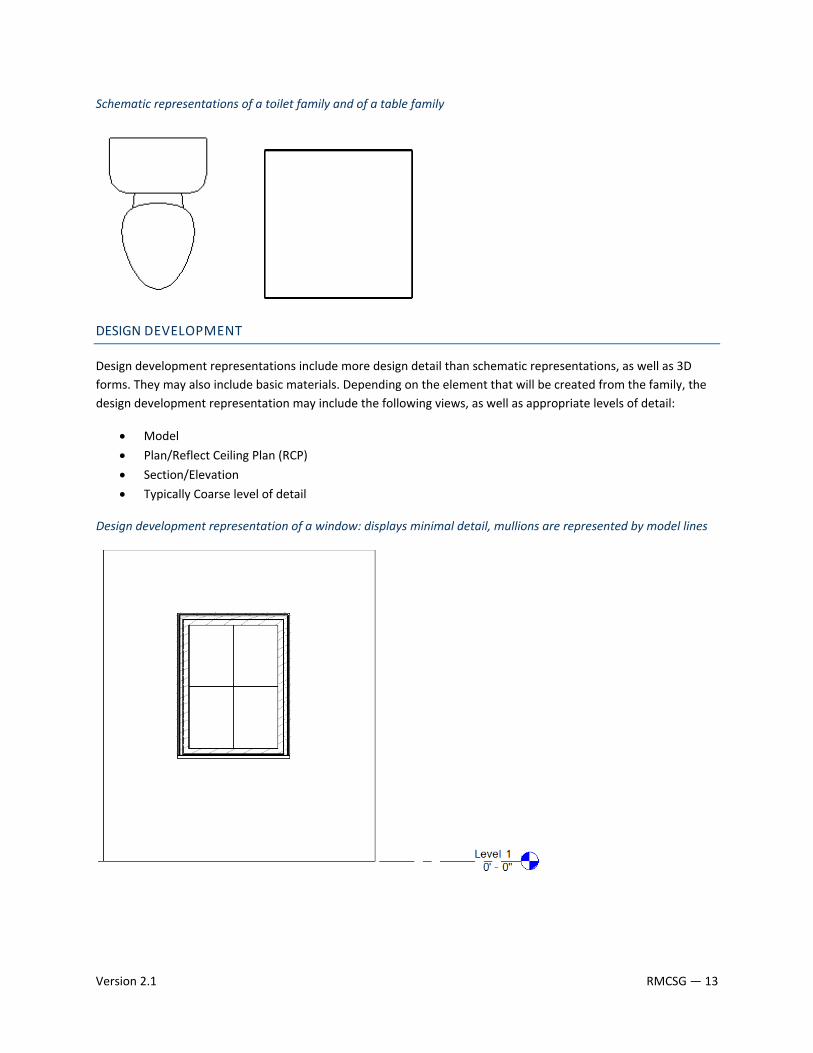
Schematic representations of a toilet family and of a table family
DESIGN DEVELOPMENT
Design development representations include more design detail than schematic representations, as well as 3D forms. They may also include basic materials. Depending on the element that will be created from the family, the design development representation may include the following views, as well as appropriate levels of detail:
• Model
• Plan/Reflect Ceiling Plan (RCP)
• Section/Elevation
• Typically Coarse level of detail
Design development representation of a window: displays minimal detail, mullions are represented by model lines
Version 2.1 RMCSG — 13
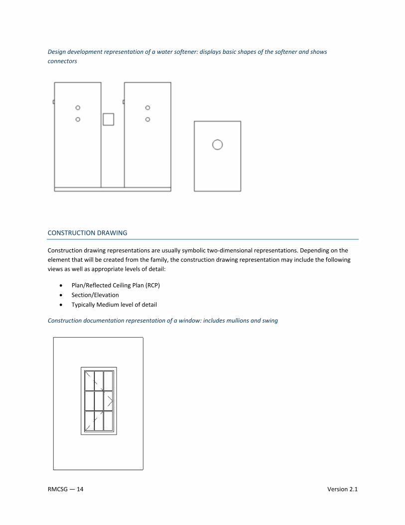
Design development representation of a water softener: displays basic shapes of the softener and shows connectors
CONSTRUCTION DRAWING
Construction drawing representations are usually symbolic two‐dimensional representations. Depending on the element that will be created from the family, the construction drawing representation may include the following views as well as appropriate levels of detail:
• Plan/Reflected Ceiling Plan (RCP)
• Section/Elevation
• Typically Medium level of detail
Construction documentation representation of a window: includes mullions and swing
RMCSG — 14 Version 2.1
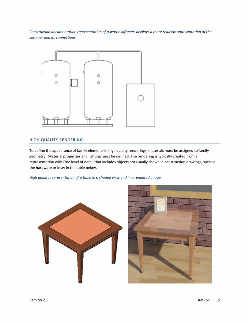
Construction documentation representation of a water softener: displays a more realistic representation of the softener and its connections
HIGH QUALITY RENDERING
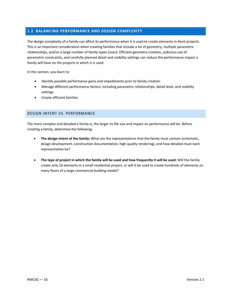
To define the appearance of family elements in high quality renderings, materials must be assigned to family geometry. Material properties and lighting must be defined. The rendering is typically created from a representation with Fine level of detail that includes objects not usually shown in construction drawings, such as the hardware or inlay in the table below.
High quality representation of a table in a shaded view and in a rendered image
Version 2.1 RMCSG — 15
1.2 BALANCING PERFORMANCE AND DESIGN COMPLEXITY
The design complexity of a family can affect its performance when it is used to create elements in Revit projects. This is an important consideration when creating families that include a lot of geometry, multiple parametric relationships, and/or a large number of family types (sizes). Efficient geometry creation, judicious use of parametric constraints, and carefully planned detail and visibility settings can reduce the performance impact a family will have on the projects in which it is used.
In this section, you learn to:
• Identify possible performance gains and impediments prior to family creation
• Manage different performance factors, including parametric relationships, detail level, and visibility settings
• Create efficient families
DESIGN INTENT VS. PERFORMANCE
The more complex and detailed a family is, the larger its file size and impact on performance will be. Before creating a family, determine the following:
• The design intent of the family: What are the representations that the family must contain (schematic, design development, construction documentation, high quality rendering), and how detailed must each representation be?
• The type of project in which the family will be used and how frequently it will be used: Will the family create only 10 elements in a small residential project, or will it be used to create hundreds of elements on many floors of a large commercial building model?
RMCSG — 16 Version 2.1
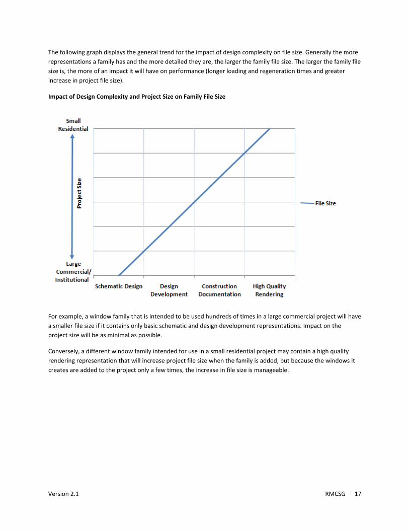
The following graph displays the general trend for the impact of design complexity on file size. Generally the more representations a family has and the more detailed they are, the larger the family file size. The larger the family file size is, the more of an impact it will have on performance (longer loading and regeneration times and greater increase in project file size).
Impact of Design Complexity and Project Size on Family File Size
For example, a window family that is intended to be used hundreds of times in a large commercial project will have a smaller file size if it contains only basic schematic and design development representations. Impact on the project size will be as minimal as possible.
Conversely, a different window family intended for use in a small residential project may contain a high quality rendering representation that will increase project file size when the family is added, but because the windows it creates are added to the project only a few times, the increase in file size is manageable.
Version 2.1 RMCSG — 17

RECOMMENDED FAMILY FILE SIZES
To provide content creators with a tangible guideline for family file size, some common family types and their recommended file sizes are listed below. Use the file sizes below as a recommendation, as actual size may vary. Large, complex, and/or unusual families may exceed these recommendations.
Application Element Complexity Level File Size Revit Architecture Casework Simple 200 – 300 K Complex 500 K Door (single‐panel) Simple 300 – 400 K Complex 600 K Furniture System Simple 200 – 300 K Complex 500 K Window (single‐unit) Simple 300 – 400 K Complex 600 K Revit MEP Air Handler Unit Simple 300 – 400 K Complex 800 K – 1000 K Chiller Simple 300 – 400 K Complex 800 K Fan Simple 200 – 300 K Complex 400 K Plumbing Fixture Simple 300 – 400 K Complex 600 K Revit Structure W‐Shape Simple 180 – 200 K Complex 300 K
IMPORTANT: To help reduce the file size, in Revit, click File→Purge Unused to delete items that are not in use, click File menu→Save As, and verify that the Compact File option is selected when saving the file.
RMCSG — 18 Version 2.1
LEVEL OF DETAIL
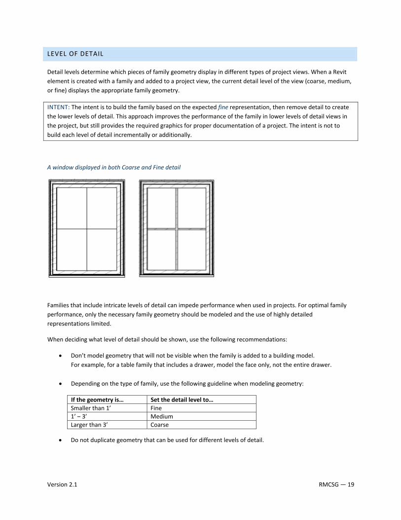
Detail levels determine which pieces of family geometry display in different types of project views. When a Revit element is created with a family and added to a project view, the current detail level of the view (coarse, medium, or fine) displays the appropriate family geometry.
INTENT: The intent is to build the family based on the expected fine representation, then remove detail to create the lower levels of detail. This approach improves the performance of the family in lower levels of detail views in the project, but still provides the required graphics for proper documentation of a project. The intent is not to build each level of detail incrementally or additionally.
A window displayed in both Coarse and Fine detail
Families that include intricate levels of detail can impede performance when used in projects. For optimal family performance, only the necessary family geometry should be modeled and the use of highly detailed representations limited.
When deciding what level of detail should be shown, use the following recommendations:
• Don’t model geometry that will not be visible when the family is added to a building model. For example, for a table family that includes a drawer, model the face only, not the entire drawer.
• Depending on the type of family, use the following guideline when modeling geometry:
If the geometry is… Set the detail level to…Smaller than 1’ Fine1’ – 3’ MediumLarger than 3’ Coarse
• Do not duplicate geometry that can be used for different levels of detail.
Version 2.1 RMCSG — 19
ELEMENT VISIBILITY
Typically, the geometry of an element created by a family will change depending on the current project view. The visibility settings of the family determine in which project views elements created with the family will display.
In a plan view, you may want to see a 2D representation of the element. In a 3D or elevation view, you may want to display a fully detailed 3D representation of the element. In other views, you may want to hide the element. Limiting the visibility of highly detailed family geometry to only certain views can improve project performance.
AREAS TO AVOID FOR OPTIMUM PERFORMANCE
Use this table as a guide to improve the performance of your families.
Common Mistake When Creating Families Recommended ApproachLack of planning prior to family creation Before creating a family, use the guidelines outlined in
1.4 Planning a Revit Model Family.
Unnecessary parametric relationships Before adding geometry to a family: • Plan the parametric relationships and create a
family skeleton that features the main parametric relationships.
• Build only the parametric family behavior that you need to avoid over‐constraining the model.
• Flex the skeleton to test the relationships before you add geometry.
Use of geometry instead of symbolic lines in plan views In plan view representations, geometry usually can be represented with symbolic lines, rather than (solid) geometry. Using geometry instead of symbolic lines will create an unnecessarily larger family.
High levels of geometric detail and underuse of visibility settings
Use the guidelines in the Level of Detail and Element Visibility sections of this guide to avoid unnecessarily large family files.
Overuse of voids, formulas, and arrays Extensive use of voids, formulas, and arrays will add to the overall family size and affect its performance in projects.
Use of too many nested families (families imported into other families)
Nest families to create geometry in other families only when necessary. Only use nested content to share objects among multiple families, for example, door hardware, muntin patterns, and so on.
Large families with many types that do not include type catalogs
The more types (particularly unused) the heavier the family. Create type catalogs for families that contain 6 or more types. See 2.10 Type Catalog Standards and Usage.
Inadequate family testing See 3.1 General Family Testing Guidelines.
RMCSG — 20 Version 2.1
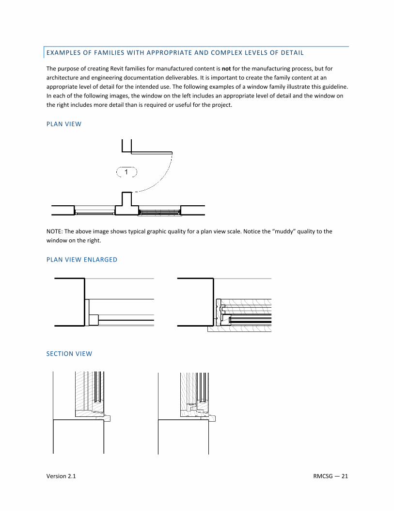
EXAMPLES OF FAMILIES WITH APPROPRIATE AND COMPLEX LEVELS OF DETAIL
The purpose of creating Revit families for manufactured content is not for the manufacturing process, but for architecture and engineering documentation deliverables. It is important to create the family content at an appropriate level of detail for the intended use. The following examples of a window family illustrate this guideline. In each of the following images, the window on the left includes an appropriate level of detail and the window on the right includes more detail than is required or useful for the project.
PLAN VIEW
NOTE: The above image shows typical graphic quality for a plan view scale. Notice the “muddy” quality to the window on the right.
PLAN VIEW ENLARGED
SECTION VIEW
Version 2.1 RMCSG — 21
CONSIDERATIONS FOR NESTING FAMILY CONTENT
A nested family is one that has been loaded into another family. In some cases, it can be convenient to represent parts of the nested family separately from the main family model. For example, you could create a windowsill family and nest it in a window family. This allows you to build upon previous work while creating families suited to your needs.
IMPORTANT: It is important to understand that nesting families increases the file size and affects performance, specifically the regeneration process of the family views.
NESTING RECOMMENDATIONS:
• Instead of nesting, consider creating all of the necessary geometry in the family. Use reference lines and labels to lock geometry in place.
• Limit nesting to 2 levels ‐ The deeper that families are nested, the longer they take to update in the project file.
• Only nest high‐value content that may be used in several different families, such as a door handle.
Be careful when changing a nested component that is shared by more than one family. When you reload the component into the project file it will update all of the families in the file sharing the same nested family.
RMCSG — 22 Version 2.1
1.3 AUTODESK EXCHANGE FORMAT (.ADSK)
Starting in the 2010 release of Autodesk products, the Autodesk Exchange format (.ADSK) provides an improved method for manufacturers to leverage Digital Prototypes to produce Revit Families. The Inventor 2010 AEC Exchange environment provides manufacturers with the ability to provide their existing Digital Prototypes as .ADSK files, which can contain a simplified 3D geometric representation, intelligent connectors, and other product metadata that can be read by Revit Architecture 2010, Revit MEP 2010, AutoCAD Architecture 2010, and AutoCAD MEP 2010 software. By reusing the information from existing CAD designs, manufacturers and their customers can avoid the time and expense required to remodel this data.
AEC EXCHANGE ENVIRONMENT
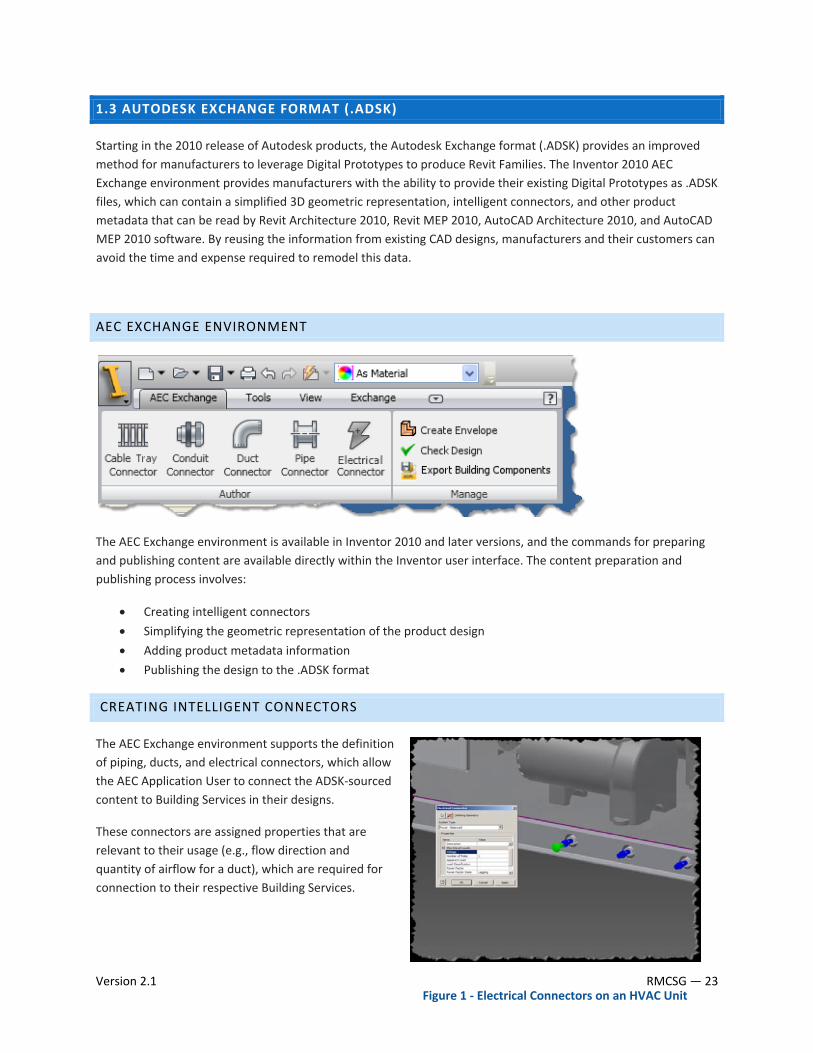
The AEC Exchange environment is available in Inventor 2010 and later versions, and the commands for preparing and publishing content are available directly within the Inventor user interface. The content preparation and publishing process involves:
• Creating intelligent connectors
• Simplifying the geometric representation of the product design
• Adding product metadata information
• Publishing the design to the .ADSK format
CREATING INTELLIGENT CONNECTORS
The AEC Exchange environment supports the definition of piping, ducts, and electrical connectors, which allow the AEC Application User to connect the ADSK‐sourced content to Building Services in their designs.
These connectors are assigned properties that are relevant to their usage (e.g., flow direction and quantity of airflow for a duct), which are required for connection to their respective Building Services.
Version 2.1 RMCSG — 23 Figure 1 ‐ Electrical Connectors on an HVAC Unit
SIMPLIFYING THE GEOMETRIC REPRESENTATION
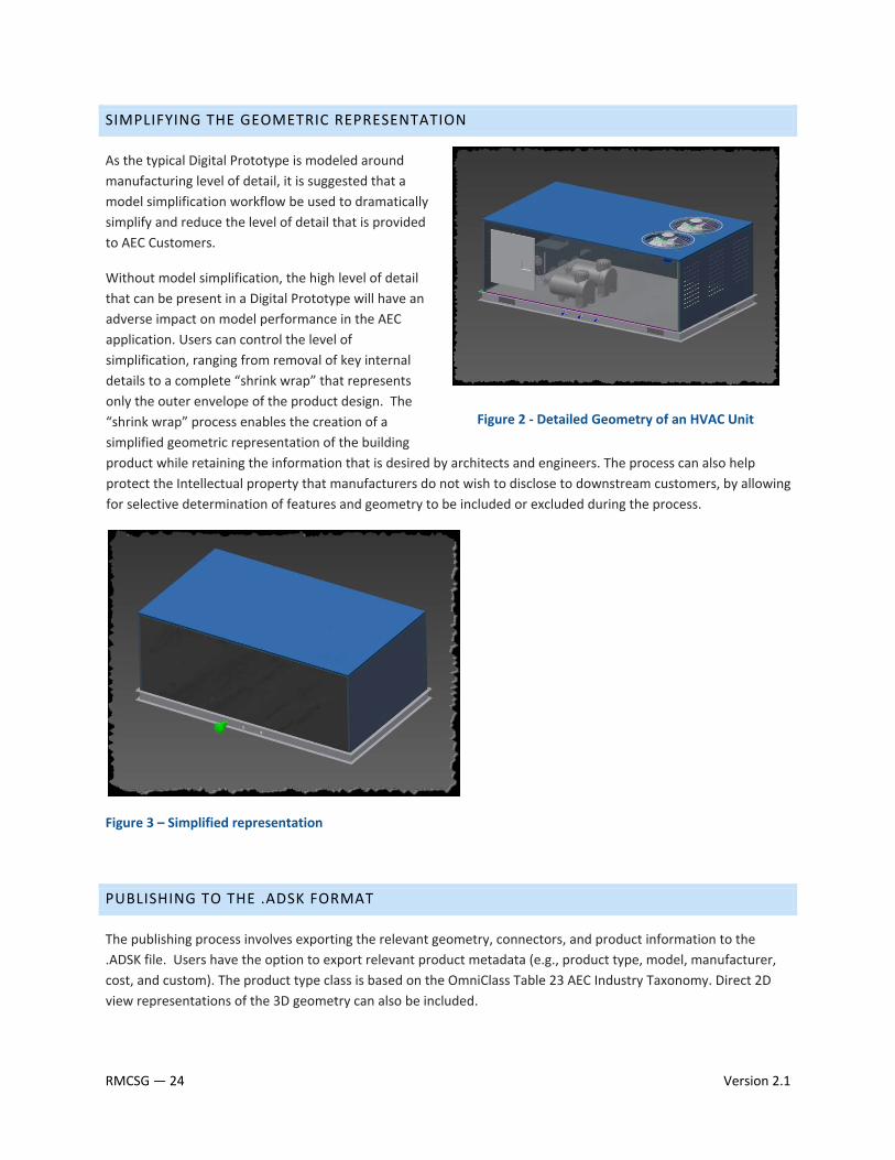
As the typical Digital Prototype is modeled around manufacturing level of detail, it is suggested that a model simplification workflow be used to dramatically simplify and reduce the level of detail that is provided to AEC Customers.
Without model simplification, the high level of detail that can be present in a Digital Prototype will have an adverse impact on model performance in the AEC application. Users can control the level of simplification, ranging from removal of key internal details to a complete “shrink wrap” that represents only the outer envelope of the product design. The “shrink wrap” process enables the creation of a simplified geometric representation of the building product while retaining the information that is desired by architects and engineers. The process can also help protect the Intellectual property that manufacturers do not wish to disclose to downstream customers, by allowing for selective determination of features and geometry to be included or excluded during the process.
Figure 2 ‐ Detailed Geometry of an HVAC Unit
Figure 3 – Simplified representation
PUBLISHING TO THE .ADSK FORMAT
The publishing process involves exporting the relevant geometry, connectors, and product information to the .ADSK file. Users have the option to export relevant product metadata (e.g., product type, model, manufacturer, cost, and custom). The product type class is based on the OmniClass Table 23 AEC Industry Taxonomy. Direct 2D view representations of the 3D geometry can also be included.
RMCSG — 24 Version 2.1

READING .ADSK FILES
The .ADSK format can be read by Revit Architecture 2010, Revit MEP 2010, AutoCAD Architecture 2010, and AutoCAD MEP 2010 software versions or later. Information from the .ADSK file can be incorporated into the receiving application and saved out in the application’s native format.
IMPORTING INTO REVIT FAMILIES
ADSK files then can be imported into Revit Families for some post processing to help meet the requirements of the Revit Model Content Style Guide. This process will be discussed in more detail in a future appendix.
LIMITATIONS
There are limitations to ADSK‐sourced content which should be understood in order to maximize the value for manufacturers and their specifying AEC customers. Note that some of these limitations can be mitigated with post‐processing of the ADSK files after it has been consumed by Revit.
• As a result of the model simplification process in Inventor and differences between the Inventor and AEC product’s Parametric geometry handling, the geometry that is currently produced for AEC applications through the AEC Exchange Environment, is static, and cannot be edited directly by the AEC user. It will appear as imported geometry.
• ADSK files do not currently contain visual appearance information, and there is no way within Revit products to manually modify their appearance.
• ADSK files do not currently support Revit Hosting behavior, and therefore the content cannot be placed on Faces of Building Elements, or have holes cut in them. Integrating the content into a Revit family (.rfa) file can help remove this limitation.
• Light Source Definitions cannot currently be defined in ADSK files, and thus must be manually added in the Revit environment if needed. Integrating them into a Revit family (.rfa) file can help remove this limitation.
As a result of current limitations, ADSK files are most effective for delivering configured engineering products that do not require a high level of variability for use by the end user.
Version 2.1 RMCSG — 25
1.4 USING IMPORTED CONTENT
Content created in other CAD formats may be imported and used to create Revit family content. Imported content may include geometry, metadata such as product performance information, connectors, and views. The use of such imported geometry does not offer all of the capabilities available with the .ADSK format (see Section 1.3) but is an option if .ADSK data is not available.
When importing geometry from other CAD formats, for optimal results and integral family functionality, it is recommended that the imported geometry is used as a guide for family creation, not as the family geometry itself.
NOTE: It is acceptable to use imported geometry for content that is difficult to create geometrically in Revit, such as people, trees, cars, etc.
SUPPORTED CONTENT
Revit families support the import of content created in the following CAD file formats:
• .DWG (Autodesk AutoCAD format)
• .DXF (AutoCAD Drawing Interchange Format)
• .SAT (Spatial Corporation Standard ACIS format)
• .SKP (Google SketchUp Model format)
LIMITATIONS
If you import content into a family and use it to create the family without modification, the resulting family types will be added to building models as static elements that do not support the dynamic parametric relationships inherent in Revit building models. Families created directly from imported content do not support direct assignment of materials and other parameters, limiting their overall use in the project environment. Imported content may also have adverse effects on project performance. In some cases, these limitations may be acceptable, but to conform to standard building information modeling practice, it is recommended that most imported content should be recreated as a fully functional Revit family.
RMCSG — 26 Version 2.1
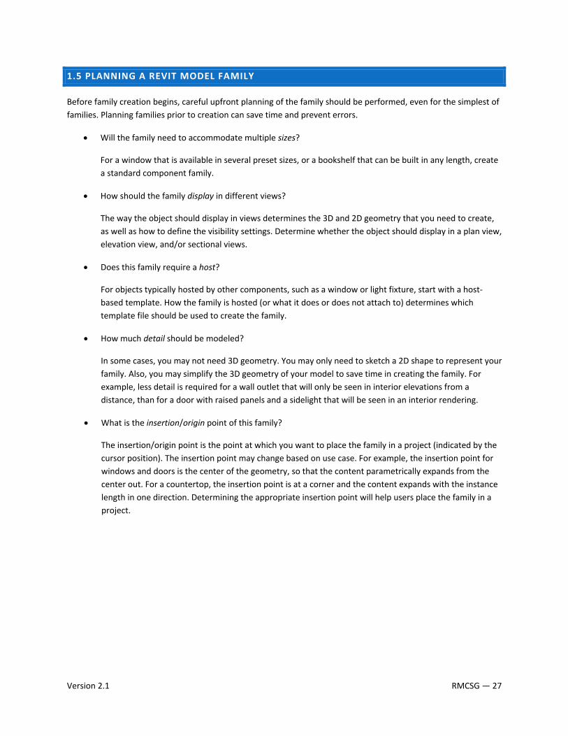
1.5 PLANNING A REVIT MODEL FAMILY
Before family creation begins, careful upfront planning of the family should be performed, even for the simplest of families. Planning families prior to creation can save time and prevent errors.
• Will the family need to accommodate multiple sizes?
For a window that is available in several preset sizes, or a bookshelf that can be built in any length, create a standard component family.
• How should the family display in different views?
The way the object should display in views determines the 3D and 2D geometry that you need to create, as well as how to define the visibility settings. Determine whether the object should display in a plan view, elevation view, and/or sectional views.
• Does this family require a host?
For objects typically hosted by other components, such as a window or light fixture, start with a host‐based template. How the family is hosted (or what it does or does not attach to) determines which template file should be used to create the family.
• How much detail should be modeled?
In some cases, you may not need 3D geometry. You may only need to sketch a 2D shape to represent your family. Also, you may simplify the 3D geometry of your model to save time in creating the family. For example, less detail is required for a wall outlet that will only be seen in interior elevations from a distance, than for a door with raised panels and a sidelight that will be seen in an interior rendering.
• What is the insertion/origin point of this family?
The insertion/origin point is the point at which you want to place the family in a project (indicated by the cursor position). The insertion point may change based on use case. For example, the insertion point for windows and doors is the center of the geometry, so that the content parametrically expands from the center out. For a countertop, the insertion point is at a corner and the content expands with the instance length in one direction. Determining the appropriate insertion point will help users place the family in a project.
Version 2.1 RMCSG — 27
SECTION 2: MODEL CONTENT CREATION STANDARDS In order to ensure Revit model content is developed efficiently, consistently, and to Autodesk standards, content creators should follow the Autodesk‐approved standards in this section when creating Revit families. Use the topics in this section to:
• ensure consistency and stability of your Revit family content
• ensure a consistent user experience
• create content suitable to share on Autodesk Seek
RMCSG — 28 Version 2.1
2.1 WORKFLOW FOR MODEL CONTENT CREATION
Before you create a model family, review the standards in this section, and then use the best practice workflow below to create your content. This workflow helps to ensure that your content is created in the most efficient and least error‐prone manner.
1. Create a new family file (.rfa) with the appropriate family template.
2. Define subcategories for the family to help control the visibility of the family geometry.
3. Create the family skeleton, or framework:
• Define the origin (the insertion point) of the family.
• Lay out reference planes to snap to when you sketch component geometry.
• Add dimensions to specify parametric relationships.
• Label dimensions to create type or instance parameters or 2D representation.
• Test, or flex, the skeleton.
4. Define family type variations by specifying different parameters.
5. Add a single level of geometry in solids and voids, and constrain the geometry to reference planes.
6. Flex the new model (types and hosts) to verify correct component behavior.
7. Repeat previous steps until the family geometry is complete.
8. Specify 2D and 3D geometry display characteristics with subcategory and entity visibility settings.
9. Save the family, and then test it.
10. For large families that include many types, create a type catalog.
TIP: For more information on the steps in this workflow, download the Revit® Architecture 2009 Families Guide (www.autodesk.com/revitarchitecture‐documentation), and see the Creating Standard Component Families topic.
Version 2.1 RMCSG — 29
PROTOTYPING
If you need to create a number of similar families:
1. Plan and create a single “prototype” family.
2. Test the prototype family in the Family Editor and in a project environment to identify any errors or inconsistencies. See Section 3: Testing Guidelines for testing criteria.
3. Correct any errors and inconsistencies and retest the family to ensure it is works properly before creating the additional families.
2.2 FAMILY UNITS
Although families can be created as unit‐specific (imperial or metric), Revit software stores all coordinates in universal units and displays specific units according to user preference. This means that:
• Units can be set to display as necessary for a target audience (i.e., display as decimal units for a civil engineering drawing or fractional units for an architectural drawing).
• Families created in imperial units may be loaded into and used in metric projects and vice versa.
For information on changing the display of units, see “Project Units” in the Revit Help.
To use an imperial or metric family in a project with different base units, use one of the following options:
• Load the family in the project where it will use the current project units. However, any imperial‐ or metric‐specific text in the family name, type names, and parameter names will still display as metric unless explicitly changed. Standards sizes may also need to be adjusted.
• Duplicate the types within a metric or imperial family to create both imperial and metric types within the family.
• Open the family, save it as a new family, and change the units.
RMCSG — 30 Version 2.1
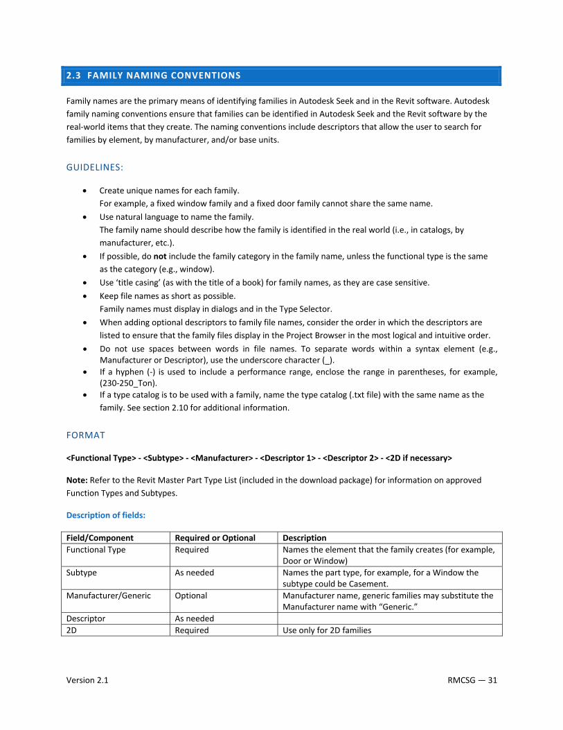
2.3 FAMILY NAMING CONVENTIONS
Family names are the primary means of identifying families in Autodesk Seek and in the Revit software. Autodesk family naming conventions ensure that families can be identified in Autodesk Seek and the Revit software by the real‐world items that they create. The naming conventions include descriptors that allow the user to search for families by element, by manufacturer, and/or base units.
GUIDELINES:
• Create unique names for each family. For example, a fixed window family and a fixed door family cannot share the same name.
• Use natural language to name the family. The family name should describe how the family is identified in the real world (i.e., in catalogs, by manufacturer, etc.).
• If possible, do not include the family category in the family name, unless the functional type is the same as the category (e.g., window).
• Use ‘title casing’ (as with the title of a book) for family names, as they are case sensitive.
• Keep file names as short as possible. Family names must display in dialogs and in the Type Selector.
• When adding optional descriptors to family file names, consider the order in which the descriptors are listed to ensure that the family files display in the Project Browser in the most logical and intuitive order.
• Do not use spaces between words in file names. To separate words within a syntax element (e.g., Manufacturer or Descriptor), use the underscore character (_).
• If a hyphen (‐) is used to include a performance range, enclose the range in parentheses, for example, (230‐250_Ton).
• If a type catalog is to be used with a family, name the type catalog (.txt file) with the same name as the family. See section 2.10 for additional information.
FORMAT
<Functional Type> ‐ <Subtype> ‐ <Manufacturer> ‐ <Descriptor 1> ‐ <Descriptor 2> ‐ <2D if necessary>
Note: Refer to the Revit Master Part Type List (included in the download package) for information on approved Function Types and Subtypes.
Description of fields:
Field/Component Required or Optional DescriptionFunctional Type Required Names the element that the family creates (for example,
Door or Window) Subtype As needed Names the part type, for example, for a Window the
subtype could be Casement. Manufacturer/Generic Optional Manufacturer name, generic families may substitute the
Manufacturer name with “Generic.” Descriptor As needed 2D Required Use only for 2D families
Version 2.1 RMCSG — 31
Examples
Window–Double_Hung–Acme–Tilting_Sash–Clad.rfa
Chiller–Air_Cooled– Acme– Low_Profile.rfa
Fountain–Drinking–Acme–Polished_Chrome.rfa
Window–Double_Hung–Generic–Wood.rfa
Chiller‐Air_Cooled‐Acme‐Scroll‐(75‐100_Ton)‐Pkgd.rfa
RMCSG — 32 Version 2.1
2.4 TYPE NAMING CONVENTIONS
All families must include one predefined type. For families that create real‐world objects that are available in standard sizes, predefined types should be generated. Unless they represent nominal sizes, type names should include units or capacity, and include a unit indicator.
When naming a family type, use the format and rules below:
GUIDELINES
• Do not include the family name or category in the type name.
• Type names should mirror actual usage.
• Type names should indicate the key differences between types (size, count, material) and, when applicable, reflect standard sizes. In some cases, you may base names on size difference, but use common terms rather than numbers.
• When types are named by size, use dimensions only. Avoid the use of characters or words. (h, w, d, or height, width, depth).
• Type names should include units or capacity and a unit indicator, unless they represent nominal sizes.
• Metric types should reflect the local unit standard, unless the types are intended to be generic.
• Keep type names as short as possible. Type names must display in dialogs and in the Type Selector.
FORMAT
Unless there is a market‐specific reason to do otherwise, use the following general order in type names:
For doors and windows: <width> x <height>
For casework and furniture: <width> x <depth> x <height>
For other element types: <width> x <depth>
Version 2.1 RMCSG — 33
For unit‐specific families:
For imperial family types:
In most cases, size should be expressed in inches. Use only one of the conventions below within a family and for related families.
For families with most sizes under 10’: XX” x YY”
For families with most sizes over 10’: XX’ – YY” x AA’ – BB”
For metric family types:
For all types in metric families: XXXX x YYYYmm (or local metric unit indicator)
For families that feature nominal sizes or industry‐standard terms:
In type names, drop the dimension indicators (“,’, or mm) and/or use industry‐standard naming conventions.
Brick (industry‐standard naming): Common, Norman, CSR, Metric Modular
Lumber (nominal sizes): 2x4
Structure (industry‐standard naming): W12 x 204
EXAMPLES
TYPES FOR AN IMPERIAL WINDOW:
16” x 24” 16” x 48” 24” x 24” 24” x 48” 24” x 72” 36” x 24” 36” x 48” 36” x 72”
RMCSG — 34 Version 2.1

2.5 CATEGORY AND SUBCATEGORY STANDARDS AND USAGE
All families, including generic families, must be assigned to appropriate categories and subcategories. When a family is created, it is assigned a category. The category defines its top level of identification (for example, Door, Window, or Casework) within the project environment. When the family is used in a project, the family can be located in the Project Browser under its category, and elements created by the family types will schedule by its category. The line weight, line color, line pattern, and material assignment of the family geometry can also be assigned to by category.
To display different line weights, line colors, line patterns, and material assignments for different geometric components of the family (for example, the frame, sash, mullions, and glass that comprise a window), the components can be assigned to subcategories within the family category.
Categories are predefined in Revit software and cannot be created or changed by the user. Subcategories are predefined in some families, but other subcategories can be created in families as needed.
ADDING SUBCATEGORIES TO MODEL FAMILIES
If you need to add subcategories in your families, use the steps below to ensure that your subcategories adhere to Autodesk standards:
1. Open the list of Autodesk‐approved subcategories, Revit Master Subcategory List.xls (included in the download package).
2. Select the workbook that corresponds to the category of the family that you are creating. The first table contains any predefined subcategories that are established by the family template. The second table lists additional subcategories that you can use.
Version 2.1 RMCSG — 35
3. Determine if any of the additional subcategories fit your needs.
4. If the list does not contain the subcategories that you need, create new subcategories using the naming conventions in the next section.
5. Submit your subcategories to the Autodesk Seek team for approval. After they are approved, the subcategories will be added to the master list.
SUBCATEGORY NAMING CONVENTIONS
• Create unique names for each subcategory.
• Use natural language to name the subcategory. The subcategory name should describe how the subcategory is identified in the real world (i.e., in catalogs, by manufacturer, etc.)
• Do not include the family category in the subcategory.
• Keep subcategory names as short as possible.
• Capitalize the leading letters of the words that form the subcategory name.
RMCSG — 36 Version 2.1
2.6 AUTODESK APPROVED PARAMETER USAGE
Families contain parameters that not only create the family geometry, but identify or classify the elements that are created by the family. All families have predefined parameters that you assign values or data to, but you can add parameters that are not predefined in Revit software (that are not system parameters).
IMPORTANT: If you want to display the names and values of custom parameters in a schedule, they must be defined as shared parameters in a text file that is independent of family and project files.
REQUIREMENT: To promote consistency in model content (particularly for manufacturer content that is shared on Autodesk Seek), use parameters as they are explicitly defined (including the GUID) in the approved shared parameters file. If a required parameter is not in the file, add it to your content as necessary. It is also recommended to include the shared parameter file containing the additional parameters with your content package. When creating custom parameters, refer to 2.7 Parameter Naming Conventions.
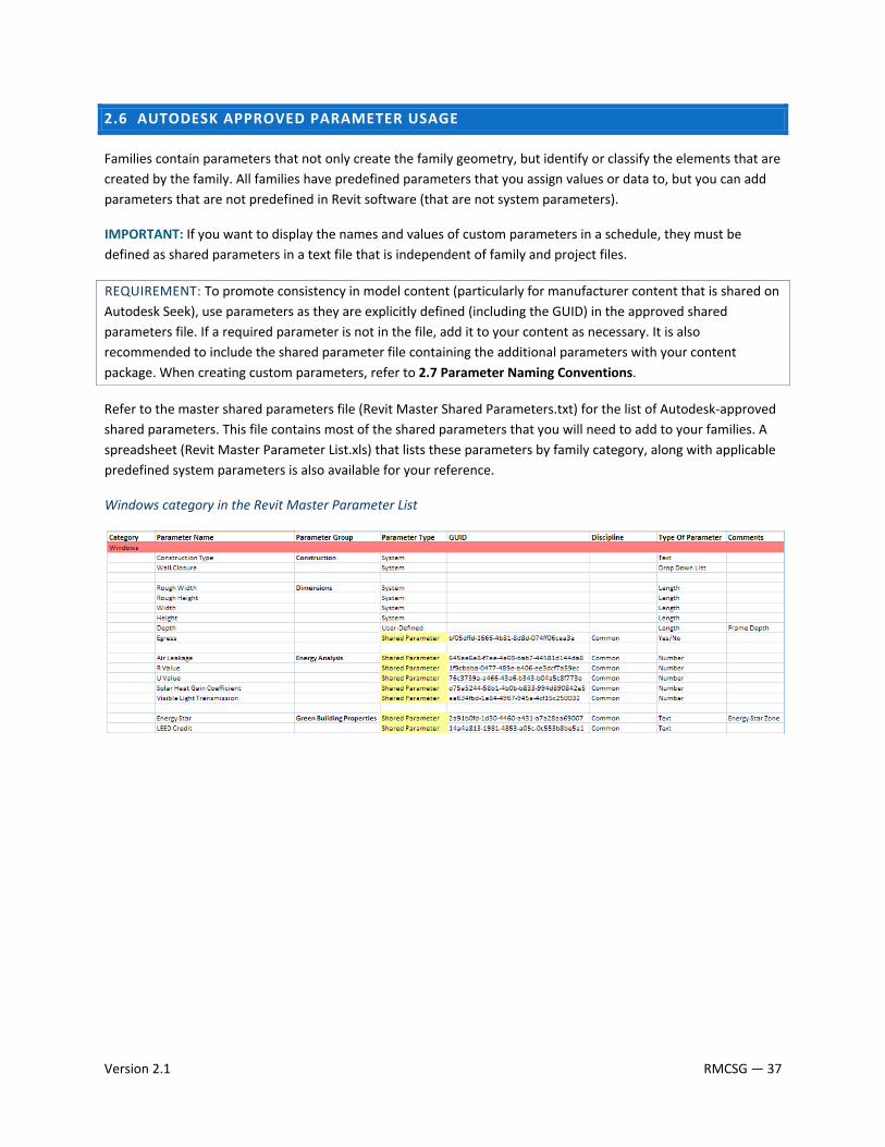
Refer to the master shared parameters file (Revit Master Shared Parameters.txt) for the list of Autodesk‐approved shared parameters. This file contains most of the shared parameters that you will need to add to your families. A spreadsheet (Revit Master Parameter List.xls) that lists these parameters by family category, along with applicable predefined system parameters is also available for your reference.
Windows category in the Revit Master Parameter List
Version 2.1 RMCSG — 37
ADDING MANUFACTURER DATA TO FAMILIES
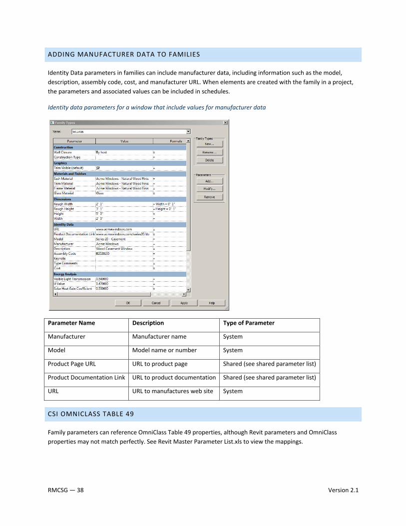
Identity Data parameters in families can include manufacturer data, including information such as the model, description, assembly code, cost, and manufacturer URL. When elements are created with the family in a project, the parameters and associated values can be included in schedules.
Identity data parameters for a window that include values for manufacturer data
Parameter Name Description Type of Parameter
Manufacturer Manufacturer name System
Model Model name or number System
Product Page URL URL to product page Shared (see shared parameter list)
Product Documentation Link URL to product documentation Shared (see shared parameter list)
URL URL to manufactures web site System
CSI OMNICLASS TABLE 49
Family parameters can reference OmniClass Table 49 properties, although Revit parameters and OmniClass properties may not match perfectly. See Revit Master Parameter List.xls to view the mappings.
RMCSG — 38 Version 2.1
CSI CLASSIFICATION CODES
On Autodesk Seek, content families can be located by the appropriate CSI (Construction Specifications Institute) code. For best results, include information in 3 format standards:
• MasterFormat 2004 – 50 divisions that standardize information in construction project manuals.
• UniFormat II (Assembly Code) – Organizing preliminary construction information based on its systems and assemblies. Used for preliminary project descriptions, performance specifying and cost estimation.
• OmniClass 1.0 – Consists of 15 tables, each representing a different facet of construction information.
For more information on the standards, refer to the CSI Web site, http://www.csinet.org/s_csi/index.asp.
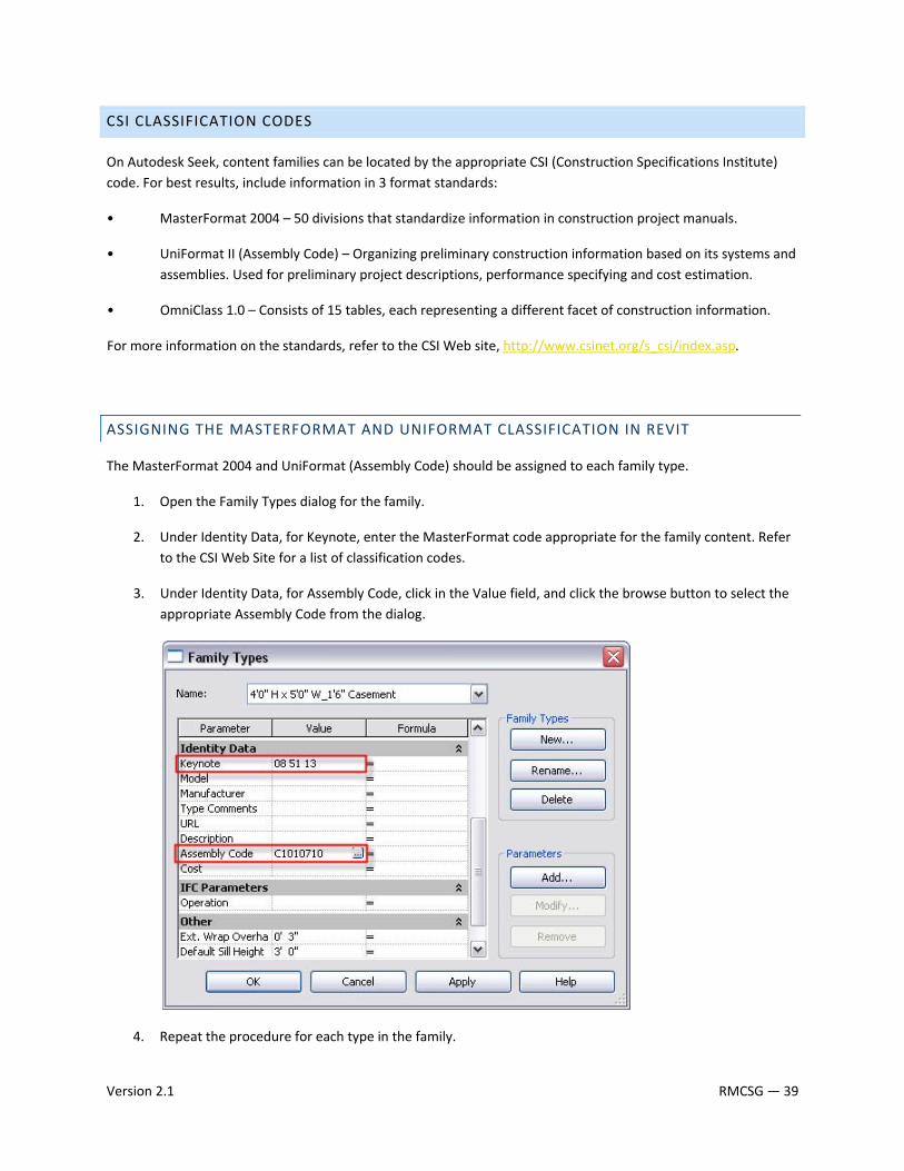
ASSIGNING THE MASTERFORMAT AND UNIFORMAT CLASSIFICATION IN REVIT
The MasterFormat 2004 and UniFormat (Assembly Code) should be assigned to each family type.
1. Open the Family Types dialog for the family.
2. Under Identity Data, for Keynote, enter the MasterFormat code appropriate for the family content. Refer to the CSI Web Site for a list of classification codes.
3. Under Identity Data, for Assembly Code, click in the Value field, and click the browse button to select the appropriate Assembly Code from the dialog.
4. Repeat the procedure for each type in the family.
Version 2.1 RMCSG — 39
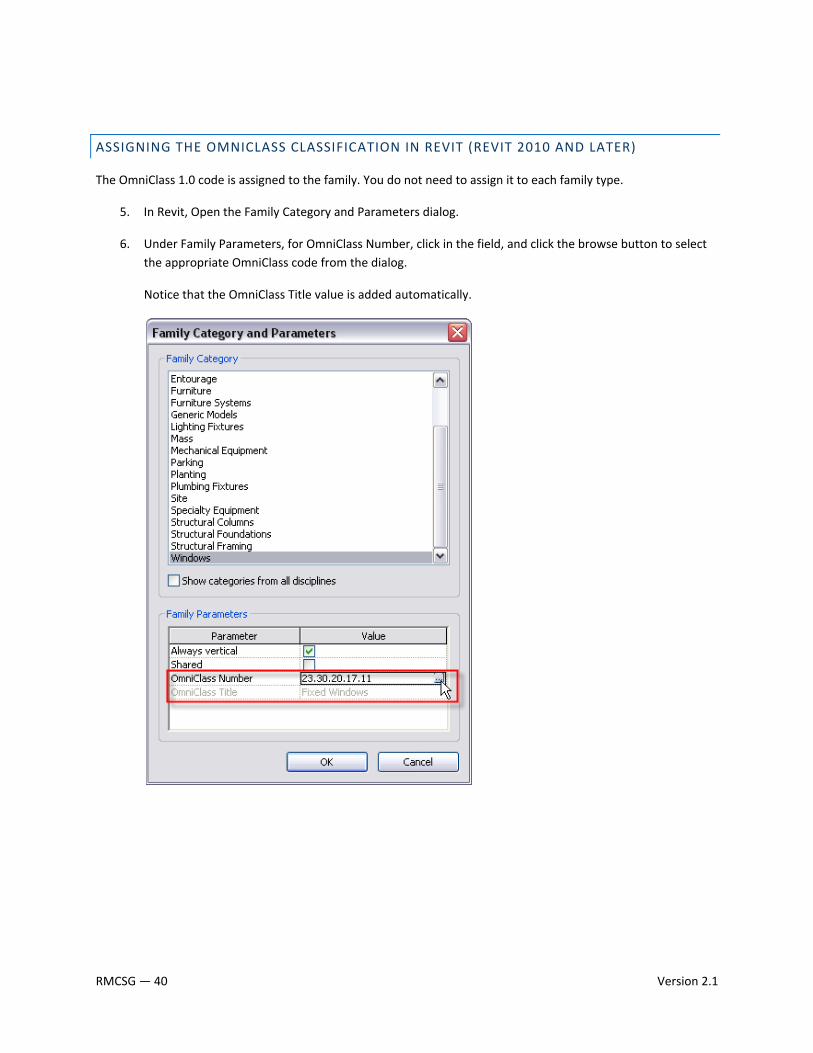
ASSIGNING THE OMNICLASS CLASSIFICATION IN REVIT (REVIT 2010 AND LATER)
The OmniClass 1.0 code is assigned to the family. You do not need to assign it to each family type.
5. In Revit, Open the Family Category and Parameters dialog.
6. Under Family Parameters, for OmniClass Number, click in the field, and click the browse button to select the appropriate OmniClass code from the dialog.
Notice that the OmniClass Title value is added automatically.
RMCSG — 40 Version 2.1
2.7 PARAMETER NAMING CONVENTIONS
Consistent parameter naming enables easier and more comprehensive parametric searching in Autodesk Seek. Create parameters only when variation creates meaningfully differentiated types that represent real‐world possibilities.
GUIDELINES
• Use standard approved parameter names when available.
• Keep parameter names as short as possible.
• Avoid abbreviation and truncation, when possible.
• Use ‘title casing’ (as with the title of a book) for parameter names, as they are case sensitive (e.g., Coefficient of Performance; Point of Shipment; High and Low Pressure Gas Connection Diameter).
• Parameters must display in dialogs.
• Do not change label names provided by the Revit family templates.
• Parameter names that you reuse to create equalities should be carefully checked for name coherence.
• Use the most common descriptor for a group of parameters as the first part of the name so that the parameters sort logically (e.g., Filter Face Area; Filter Efficiency).
• Parameters for subsequent items should include a number in the name before the final part of the description, but do not include a number in the name for the first item (e.g., Actual Hot Gas Flow; Actual Hot Gas 2 Flow).
• Avoid using symbols in parameter names, including: + ‐ / \ * ( ) “ ‘ < > | ^ $ { } [ ].
• Do not include units in the name of a parameter (e.g., Supply Air Flow CFM).
• Using the terms Actual or Design:
o Actual – describes the actual value the system definition requires. “Actual” parameters are linked to connectors and are often used for parameters that define flow rates, for example, Actual Supply Air Flow; Actual Chilled Water Flow.
o Design – describes what the product is designed to do, for example, Design Ventilation Air Flow; Design Return Air Flow.
• Name Yes/No parameters so they imply that they return a Yes/No value, for example:
o Has Handle
o Is Energy Efficient
o Show Hoods
Version 2.1 RMCSG — 41
FORMAT
<Function/Object> <Type of measurement/Descriptor>
<Function/Object> required if the parameter applies to a sub‐component rather than the entire family.
<Type of measurement/Descriptor> required for all parameters to describe the value being passed.
EXAMPLES
PARAMETERS THAT APPLY TO THE ENTIRE FAMILY
Format: <Type of measurement/Descriptor>
Casement window:
• Height
• Default Sill Height
• Width
• Window Inset
• Rough Width
• Rough Height
Engineering equipment:
• Actual Heater Gas Flow
• Total Heating Capacity
• Full Load Current
• Compressor Type
PARAMETERS THAT DESCRIBE A MEASUREMENT VALUE OF A SUB‐COMPONENT:
Format: <Function/Object> <Type of Measurement/Descriptor>
• Heat Pump Coil Face Area
• Heat Pump Coil Face Velocity
• Exhaust Fan Blade Speed
• Exhaust Fan Drive
• Exhaust Fan Motor Speed
RMCSG — 42 Version 2.1
PARAMETERS THAT DESCRIBE THE LINEAR DIMENSION OF A SUB‐COMPONENT (CONNECTOR)
Format: <Function/Object> Connection <Type of Measurement/Descriptor>
• Hot Gas Bypass 2 Connection Diameter
• Condenser Water Connection Diameter
• Supply Air Connection Width
• Supply Air Connection Height
Version 2.1 RMCSG — 43
2.8 MATERIAL NAMING CONVENTIONS
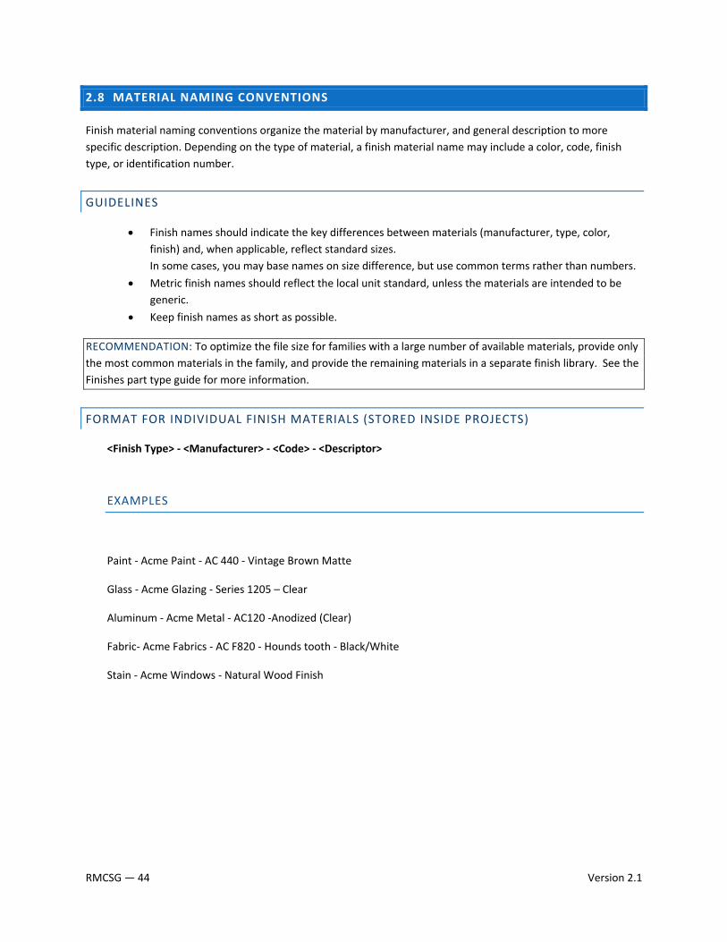
Finish material naming conventions organize the material by manufacturer, and general description to more specific description. Depending on the type of material, a finish material name may include a color, code, finish type, or identification number.
GUIDELINES
• Finish names should indicate the key differences between materials (manufacturer, type, color, finish) and, when applicable, reflect standard sizes. In some cases, you may base names on size difference, but use common terms rather than numbers.
• Metric finish names should reflect the local unit standard, unless the materials are intended to be generic.
• Keep finish names as short as possible.
RECOMMENDATION: To optimize the file size for families with a large number of available materials, provide only the most common materials in the family, and provide the remaining materials in a separate finish library. See the Finishes part type guide for more information.
FORMAT FOR INDIVIDUAL FINISH MATERIALS (STORED INSIDE PROJECTS)
<Finish Type> ‐ <Manufacturer> ‐ <Code> ‐ <Descriptor>
EXAMPLES
Paint ‐ Acme Paint ‐ AC 440 ‐ Vintage Brown Matte
Glass ‐ Acme Glazing ‐ Series 1205 – Clear
Aluminum ‐ Acme Metal ‐ AC120 ‐Anodized (Clear)
Fabric‐ Acme Fabrics ‐ AC F820 ‐ Hounds tooth ‐ Black/White
Stain ‐ Acme Windows ‐ Natural Wood Finish
RMCSG — 44 Version 2.1

FORMAT FOR INDIVIDUAL FINISH MATERIALS USING AN EXTERNAL IMAGE FILE
Materials requiring external images, bump maps and cutout should be stored in a location that can be shared by multiple Revit Product installs.
For Windows XP: C:\Documents and Settings\All Users\Application Data\Revit Manufacturer Library\Materials\<MFG> For Windows Vista and Windows 7: C:\ProgramData\All Users\Application Data\Revit Manufacturer Library\Materials\<MFG>
GUIDELINES:
• Create unique names for each unique material image.
• Capitalize the leading letters in each portion of the family name.
• Do not use spaces between words in file names. To separate words within a syntax element (e.g., Manufacturer or Descriptor), use the underscore character (_).
• Acceptable file formats for material images include: bmp, jpg, jpeg and png. • Provide a readme to describe where the image files must be located and how to map Revit to the “Revit
Manufacturer Library“ folder in the Rendering Options dialog.
FORMAT FOR INDIVIDUAL MATERIALS IMAGES (STORED OUTSIDE OF REVIT)
Material Image:
<Finish Type>‐<Manufacturer>‐<Code>‐<Descriptor> + file extension
Bump maps:
<Finish Type>‐<Manufacturer>‐<Code>‐<Descriptor>‐bump + file extension
Cutouts:
<Finish Type>‐<Manufacturer>‐<Code>‐<Descriptor>‐cutout + file extension
EXAMPLES
Image File: Paint‐Acme_Paint‐AC_440‐Vintage_Brown_Matte.jpg Stain‐Acme_Windows‐Natural_Wood_Finish.jpg Bump Image File: ‐bump.jpg Stain‐Acme_Windows‐Natural_Wood_Finish‐bump.jpg Cut‐outs/Perforations: ‐cutout.jpg Aluminum‐Acme_Fencing‐AC120‐Anodized‐cutout.jpg
Version 2.1 RMCSG — 45
2.9 PREVIEW IMAGE STANDARDS
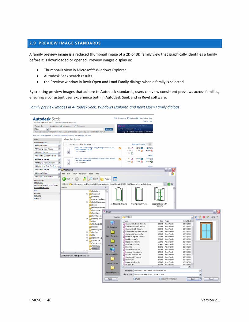
A family preview image is a reduced thumbnail image of a 2D or 3D family view that graphically identifies a family before it is downloaded or opened. Preview images display in:
• Thumbnails view in Microsoft® Windows Explorer
• Autodesk Seek search results
• the Preview window in Revit Open and Load Family dialogs when a family is selected
By creating preview images that adhere to Autodesk standards, users can view consistent previews across families, ensuring a consistent user experience both in Autodesk Seek and in Revit software.
Family preview images in Autodesk Seek, Windows Explorer, and Revit Open Family dialogs
RMCSG — 46 Version 2.1
CREATING AUTODESK STANDARD FAMILY PREVIEW IMAGES
To create a preview image, begin by creating a family view to use exclusively for the preview image. Although you can save any family view as the preview image view, the best practice is to create a view that can be set to consistently display as is required for the preview image.
After you create the view, set Autodesk standard graphic controls in the preview image view to ensure visual consistency with the preview images of other Revit families. Different graphic standards exist for the following types of family preview images:
• Detail component and annotation families
• Hosted model component families
• Non‐hosted model component families
NOTE: Although annotation families are not covered in this guide, similar standards for annotation preview images exist.
IMPORTANT: When modifications to the preview image view are complete, save the view and set the family to use the current view as the preview image. Each time you save and close the family, you must ensure that the preview image view is the active (open) view so it will display as the preview image.
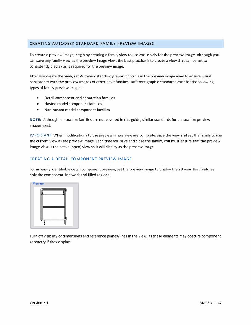
CREATING A DETAIL COMPONENT PREVIEW IMAGE
For an easily identifiable detail component preview, set the preview image to display the 2D view that features only the component line work and filled regions.
Turn off visibility of dimensions and reference planes/lines in the view, as these elements may obscure component geometry if they display.
Version 2.1 RMCSG — 47
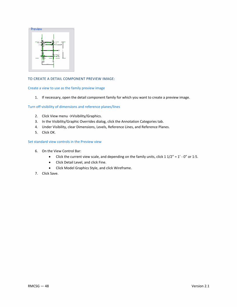
TO CREATE A DETAIL COMPONENT PREVIEW IMAGE:
Create a view to use as the family preview image
1. If necessary, open the detail component family for which you want to create a preview image.
Turn off visibility of dimensions and reference planes/lines
2. Click View menu →Visibility/Graphics. 3. In the Visibility/Graphic Overrides dialog, click the Annotation Categories tab. 4. Under Visibility, clear Dimensions, Levels, Reference Lines, and Reference Planes. 5. Click OK.
Set standard view controls in the Preview view
6. On the View Control Bar:
• Click the current view scale, and depending on the family units, click 1 1/2” = 1’ ‐ 0” or 1:5.
• Click Detail Level, and click Fine.
• Click Model Graphics Style, and click Wireframe. 7. Click Save.
RMCSG — 48 Version 2.1
CREATING A HOSTED OR NON‐HOSTED MODEL COMPONENT PREVIEW IMAGE
Depending on the type of model component that a preview image depicts, it may display a 2D or isometric view. If the preview image is created for a hosted family, host elements may or may not display in the preview.
This topic presents general guidelines for creating preview images. For additional guidelines, refer to the category‐specific documentation for model component preview images.
Create preview image views according to the following general guidelines:
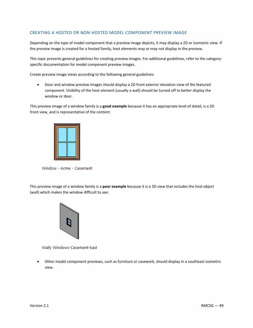
• Door and window preview images should display a 2D front exterior elevation view of the featured component. Visibility of the host element (usually a wall) should be turned off to better display the window or door.
This preview image of a window family is a good example because it has an appropriate level of detail, is a 2D front view, and is representative of the content:
This preview image of a window family is a poor example because it is a 3D view that includes the host object (wall) which makes the window difficult to see:
• Other model component previews, such as furniture or casework, should display in a southeast isometric view.
Version 2.1 RMCSG — 49
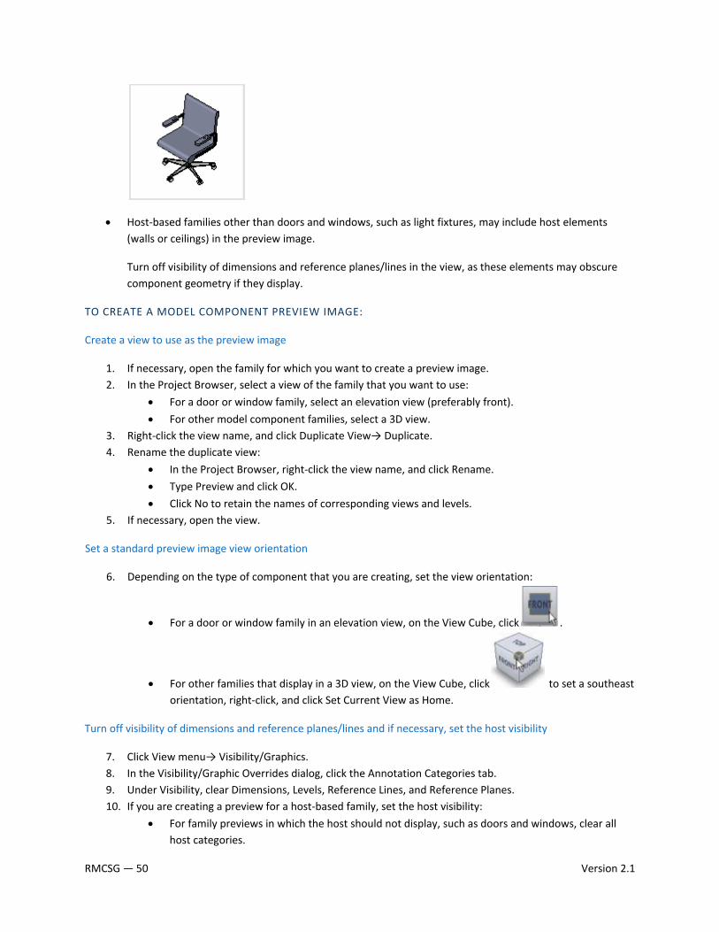
• Host‐based families other than doors and windows, such as light fixtures, may include host elements (walls or ceilings) in the preview image.
Turn off visibility of dimensions and reference planes/lines in the view, as these elements may obscure component geometry if they display.
TO CREATE A MODEL COMPONENT PREVIEW IMAGE:
Create a view to use as the preview image
1. If necessary, open the family for which you want to create a preview image. 2. In the Project Browser, select a view of the family that you want to use:
• For a door or window family, select an elevation view (preferably front).
• For other model component families, select a 3D view. 3. Right‐click the view name, and click Duplicate View→ Duplicate. 4. Rename the duplicate view:
• In the Project Browser, right‐click the view name, and click Rename.
• Type Preview and click OK.
• Click No to retain the names of corresponding views and levels. 5. If necessary, open the view.
Set a standard preview image view orientation
6. Depending on the type of component that you are creating, set the view orientation:
• For a door or window family in an elevation view, on the View Cube, click .
• For other families that display in a 3D view, on the View Cube, click to set a southeast orientation, right‐click, and click Set Current View as Home.
Turn off visibility of dimensions and reference planes/lines and if necessary, set the host visibility
7. Click View menu→ Visibility/Graphics. 8. In the Visibility/Graphic Overrides dialog, click the Annotation Categories tab. 9. Under Visibility, clear Dimensions, Levels, Reference Lines, and Reference Planes. 10. If you are creating a preview for a host‐based family, set the host visibility:
• For family previews in which the host should not display, such as doors and windows, clear all host categories.
RMCSG — 50 Version 2.1
• For family previews in which the host should display, select all host categories. 11. Click OK.
Set standard view controls in the Preview view
12. On the View Control Bar: • Click the current view scale, and depending on the family units, click 1 1/2” = 1’ ‐ 0” or 1:5.
• Click Detail Level, and click Fine.
• Click Model Graphics Style, and click Shading with Edges.
Set the preview image to display the current view
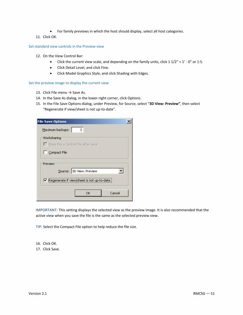
13. Click File menu → Save As. 14. In the Save As dialog, in the lower‐right corner, click Options. 15. In the File Save Options dialog, under Preview, for Source, select “3D View: Preview”, then select
“Regenerate if view/sheet is not up‐to‐date”.
IMPORTANT: This setting displays the selected view as the preview image. It is also recommended that the active view when you save the file is the same as the selected preview view. TIP: Select the Compact File option to help reduce the file size. 16. Click OK. 17. Click Save.
Version 2.1 RMCSG — 51
2.10 TYPE CATALOG STANDARDS AND USAGE
A type catalog is comma‐delimited TXT file that, when placed in the same directory as a family, displays a list of family types before the family is loaded into a project. You can select and load only the family types that the current project requires, avoiding an unnecessary increase in project size from unused types and a long list of types in the Type Selector. The type catalog also provides an external means of editing the family, as you can remove and add parameters and types in the catalog file (TXT).
TYPE CATALOG STANDARDS
Use the following standards when creating type catalogs:
• Use any text editor to create type catalogs.
• Create type catalogs for families that contain six or more types.
• Name a type catalog file (.txt) with the same name as the family file (.rfa) that it supports.
• Ensure that parameters in type catalogs are test loaded by the family for which you create the type catalog. If the parameters are not used, the family will not load.
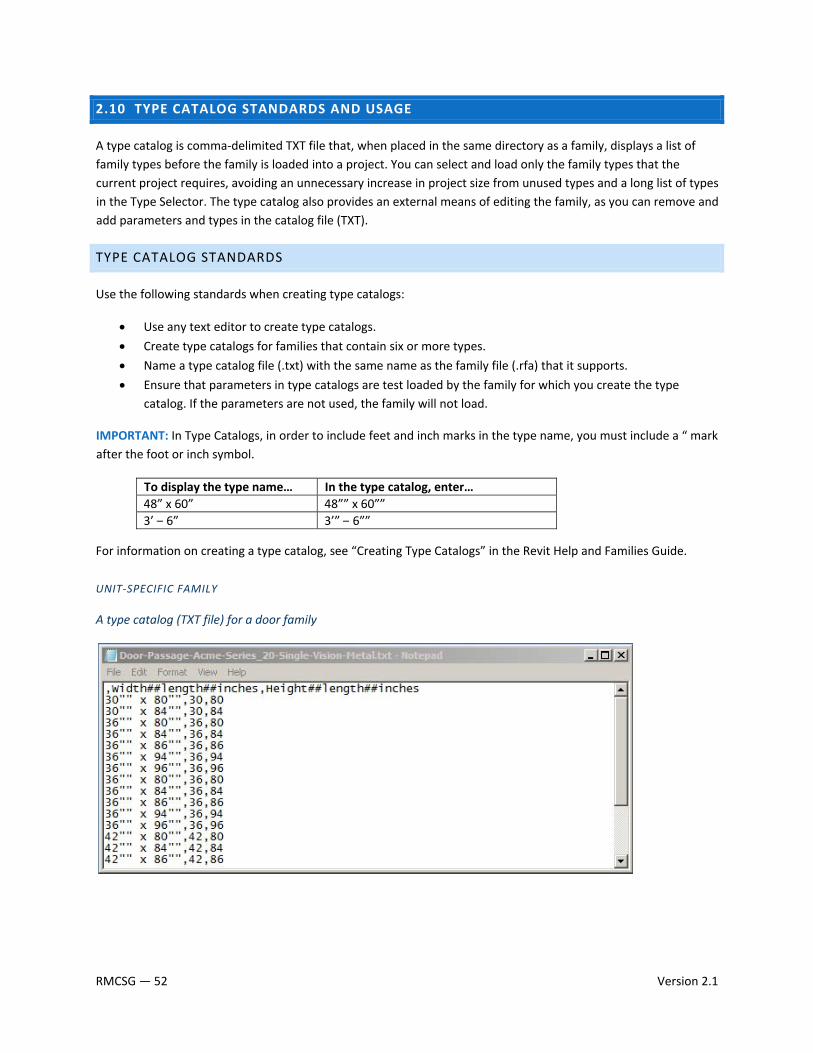
IMPORTANT: In Type Catalogs, in order to include feet and inch marks in the type name, you must include a “ mark after the foot or inch symbol.
To display the type name… In the type catalog, enter…48” x 60” 48”” x 60””3’ – 6” 3’” – 6””
For information on creating a type catalog, see “Creating Type Catalogs” in the Revit Help and Families Guide.
UNIT‐SPECIFIC FAMILY
A type catalog (TXT file) for a door family
RMCSG — 52 Version 2.1
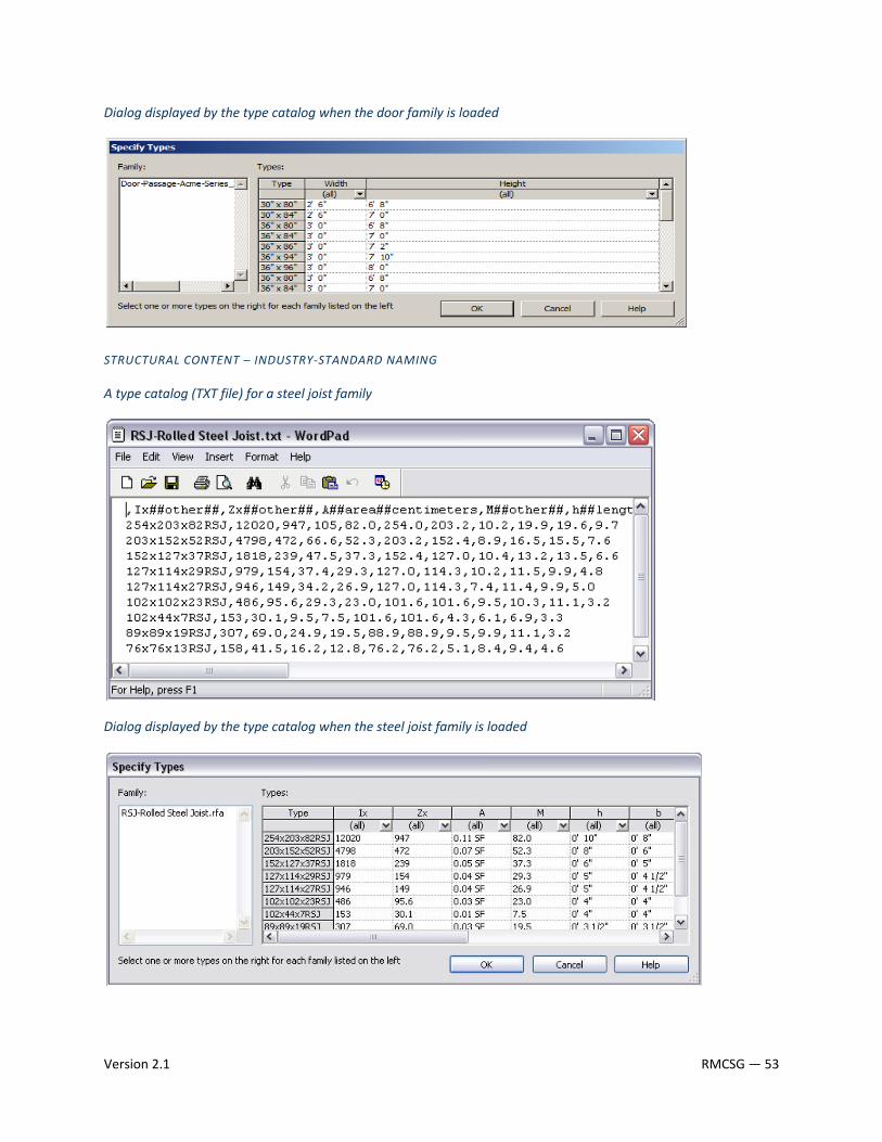
Dialog displayed by the type catalog when the door family is loaded
STRUCTURAL CONTENT – INDUSTRY‐STANDARD NAMING
A type catalog (TXT file) for a steel joist family
Dialog displayed by the type catalog when the steel joist family is loaded
Version 2.1 RMCSG — 53

2.11 MATERIAL APPLICATION IN MODEL FAMILIES
Materials can be applied to families to depict the real‐world display of elements created with the family in shaded and rendered views.
IMPORTANT: When applying materials to a family, remember that materials increase the family size, which in turn decreases its performance when it is loaded and used in projects.
Depending on how you apply materials to a family’s geometry, you can control the user’s ability to modify the materials of elements that they create with the family. Use these guidelines to apply materials to family geometry:
If you want to… Then…
use materials that will not need to be changed Apply the material directly to the family geometry by assigning it to the Material parameter (Option 1).
change the material for the family category and/or for subsets of geometric components in the family
Apply a material to the family category.
Create subcategories, assign materials to each subcategory, and assign subcategories to geometry
(Option 2).
change the material for a geometric component in a family by instance or type
Create an instance or type material parameter and assign it to the appropriate family geometry (Option 3).
NOTE: This is the most flexible and preferred method of material assignment.
If possible, use the materials that are available in the Revit software when assigning materials to family geometry. If you need to create a material, make sure that the material name conforms to the naming conventions described in the Material Naming Conventions topic.
OPTION 1 – APPLY MATERIALS WITH THE MATERIAL PARAMETER
You can apply materials directly to some or all of the family geometry in the Family Editor. Each piece of family geometry has a default Material parameter to which you can assign materials.
USE THIS METHOD WHEN:
The material of the family geometry is unlikely to change, such as for a manufactured component that is supplied with a single standard material.
RMCSG — 54 Version 2.1
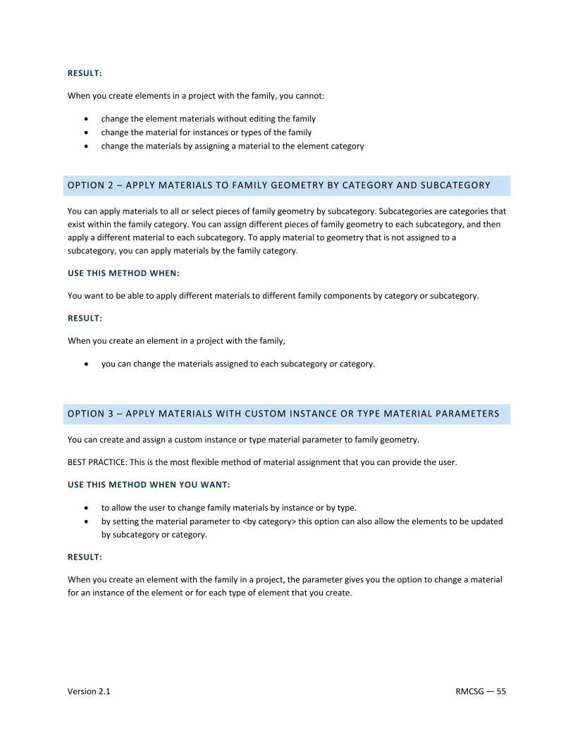
RESULT:
When you create elements in a project with the family, you cannot:
• change the element materials without editing the family
• change the material for instances or types of the family
• change the materials by assigning a material to the element category
OPTION 2 – APPLY MATERIALS TO FAMILY GEOMETRY BY CATEGORY AND SUBCATEGORY
You can apply materials to all or select pieces of family geometry by subcategory. Subcategories are categories that exist within the family category. You can assign different pieces of family geometry to each subcategory, and then apply a different material to each subcategory. To apply material to geometry that is not assigned to a subcategory, you can apply materials by the family category.
USE THIS METHOD WHEN:
You want to be able to apply different materials to different family components by category or subcategory.
RESULT:
When you create an element in a project with the family,
• you can change the materials assigned to each subcategory or category.
OPTION 3 – APPLY MATERIALS WITH CUSTOM INSTANCE OR TYPE MATERIAL PARAMETERS
You can create and assign a custom instance or type material parameter to family geometry.
BEST PRACTICE: This is the most flexible method of material assignment that you can provide the user.
USE THIS METHOD WHEN YOU WANT:
• to allow the user to change family materials by instance or by type.
• by setting the material parameter to <by category> this option can also allow the elements to be updated by subcategory or category.
RESULT:
When you create an element with the family in a project, the parameter gives you the option to change a material for an instance of the element or for each type of element that you create.
Version 2.1 RMCSG — 55
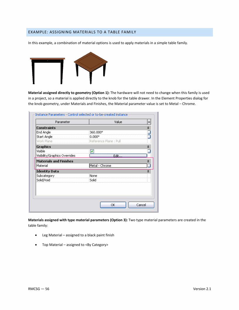
EXAMPLE: ASSIGNING MATERIALS TO A TABLE FAMILY
In this example, a combination of material options is used to apply materials in a simple table family.
Material assigned directly to geometry (Option 1): The hardware will not need to change when this family is used in a project, so a material is applied directly to the knob for the table drawer. In the Element Properties dialog for the knob geometry, under Materials and Finishes, the Material parameter value is set to Metal – Chrome.
Materials assigned with type material parameters (Option 3): Two type material parameters are created in the table family:
• Leg Material – assigned to a black paint finish
• Top Material – assigned to <By Category>
RMCSG — 56 Version 2.1
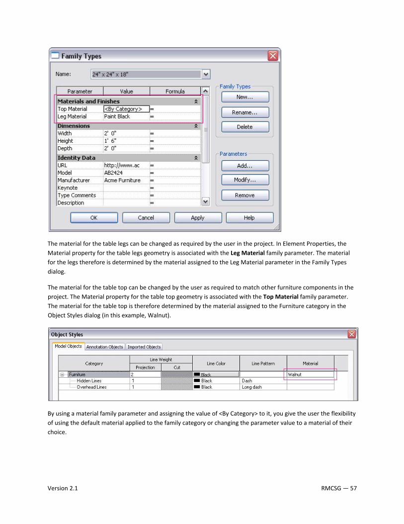
The material for the table legs can be changed as required by the user in the project. In Element Properties, the Material property for the table legs geometry is associated with the Leg Material family parameter. The material for the legs therefore is determined by the material assigned to the Leg Material parameter in the Family Types dialog.
The material for the table top can be changed by the user as required to match other furniture components in the project. The Material property for the table top geometry is associated with the Top Material family parameter. The material for the table top is therefore determined by the material assigned to the Furniture category in the Object Styles dialog (in this example, Walnut).
By using a material family parameter and assigning the value of <By Category> to it, you give the user the flexibility of using the default material applied to the family category or changing the parameter value to a material of their choice.
Version 2.1 RMCSG — 57
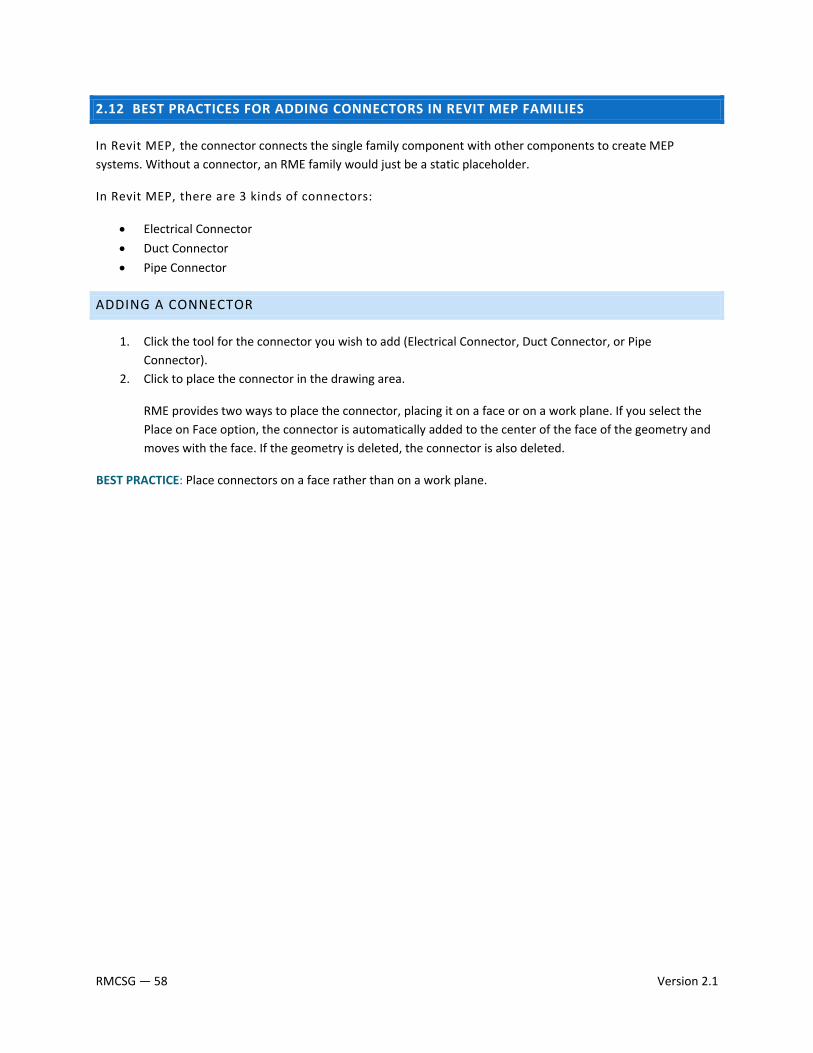
2.12 BEST PRACTICES FOR ADDING CONNECTORS IN REVIT MEP FAMILIES
In Revit MEP, the connector connects the single family component with other components to create MEP systems. Without a connector, an RME family would just be a static placeholder.
In Revit MEP, there are 3 kinds of connectors:
• Electrical Connector
• Duct Connector
• Pipe Connector
ADDING A CONNECTOR
1. Click the tool for the connector you wish to add (Electrical Connector, Duct Connector, or Pipe Connector).
2. Click to place the connector in the drawing area.
RME provides two ways to place the connector, placing it on a face or on a work plane. If you select the Place on Face option, the connector is automatically added to the center of the face of the geometry and moves with the face. If the geometry is deleted, the connector is also deleted.
BEST PRACTICE: Place connectors on a face rather than on a work plane.
RMCSG — 58 Version 2.1
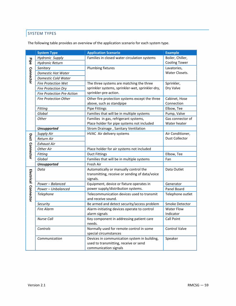
SYSTEM TYPES
The following table provides an overview of the application scenario for each system type.
System Type Application Scenario Example
Pipe Connector
Hydronic Supply Families in closed water circulation systems Boiler, Chiller, Cooling Tower Hydronic Return
Sanitary Plumbing fixtures
Lavatories, Water Closets. Domestic Hot Water
Domestic Cold Water Fire Protection Wet The three systems are matching the three
sprinkler systems, sprinkler‐wet, sprinkler‐dry, sprinkler‐pre‐action.
Sprinkler, Dry Valve Fire Protection Dry
Fire Protection Pre‐Action Fire Protection Other Other fire protection systems except the three
above, such as standpipe Cabinet, Hose Connection
Fitting Pipe Fittings Elbow, Tee Global Families that will be in multiple systems Pump, Valve Other Families in gas, refrigerant systems,
Place holder for pipe systems not included Gas connector of Water heater
Unsupported Strom Drainage , Sanitary Ventilation
Duct Connector
Supply Air HVAC Air delivery systems Air Conditioner, Dust Collector Return Air
Exhaust Air Other Air Place holder for air systems not included Fitting Duct Fittings Elbow, Tee Global Families that will be in multiple systems Fan Unsupported Fresh Air
Electrical Connector
Data Automatically or manually control the transmitting, receive or sending of data/voice signals.
Data Outlet
Power – Balanced Equipment, device or fixture operates in power supply/distribution systems.
Generator Power – Unbalanced Panel Board Telephone Telecommunication devices used to transmit
and receive sound. Telephone outlet
Security Be armed and detect security/access problem Smoke DetectorFire Alarm Alarm‐initiating devices operate to control
alarm signals Water Flow Indicator
Nurse Call Key component in addressing patient care needs.
Call Point
Controls Normally used for remote control in some special circumstances
Control Valve
Communication Devices in communication system in building, used to transmitting, receive or send communication signals
Speaker
Version 2.1 RMCSG — 59

CONNECTOR DIRECTION
For duct/pipe connectors, an arrow, perpendicular to the surface, displays. The direction that the arrow is pointing is also the direction in which the connecting duct/pipe will be drawn. As the picture shows, vertical duct can be drawn from an up connector in an air terminal.
NOTE: The arrow does not represent the flow direction.
PRIMARY CONNECTOR
By default, the first connector in each domain is assigned as the primary connector. In the following image, you can easily identify the primary connector (connector 1) by the cross symbol. The Re‐assign Primary tool allows you to reassign the primary connector, as required.
The primary connector of pipe and duct fittings should be located at coordinates (‐1, 0, 0). In the following image of the plan view of a P‐Trap, connector 1 is the primary connector.
RMCSG — 60 Version 2.1
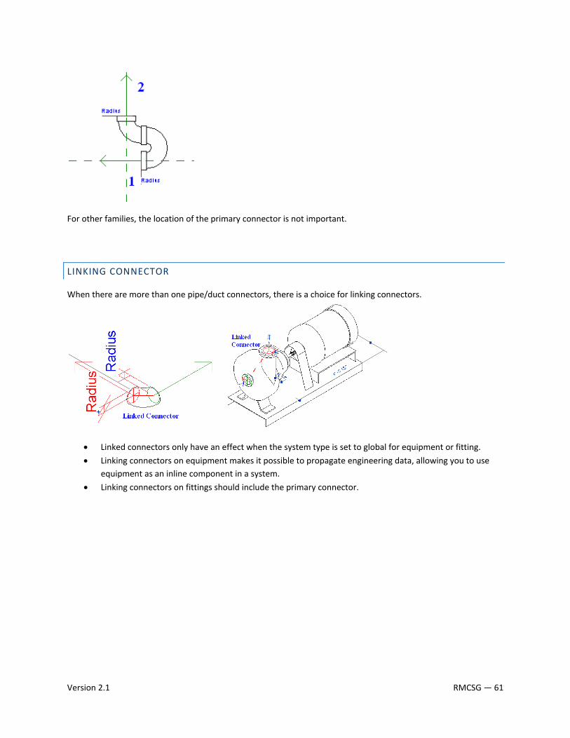
For other families, the location of the primary connector is not important.
LINKING CONNECTOR
When there are more than one pipe/duct connectors, there is a choice for linking connectors.
• Linked connectors only have an effect when the system type is set to global for equipment or fitting.
• Linking connectors on equipment makes it possible to propagate engineering data, allowing you to use equipment as an inline component in a system.
• Linking connectors on fittings should include the primary connector.
Version 2.1 RMCSG — 61
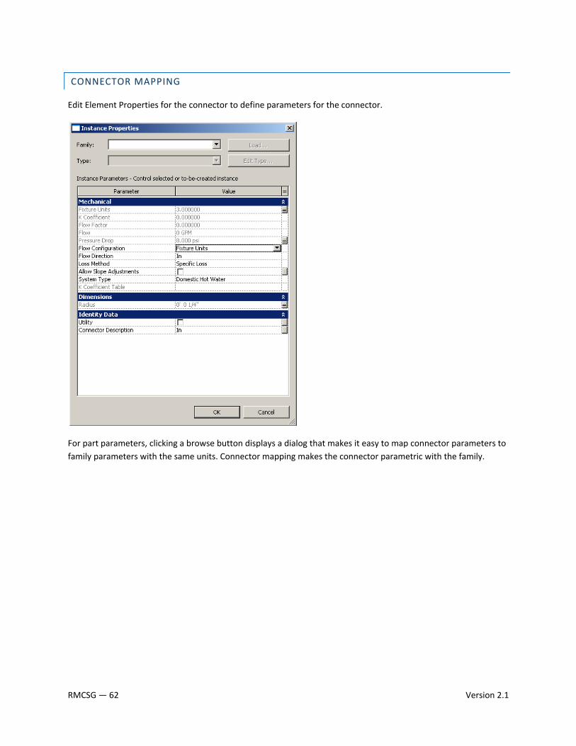
CONNECTOR MAPPING
Edit Element Properties for the connector to define parameters for the connector.
For part parameters, clicking a browse button displays a dialog that makes it easy to map connector parameters to family parameters with the same units. Connector mapping makes the connector parametric with the family.
RMCSG — 62 Version 2.1
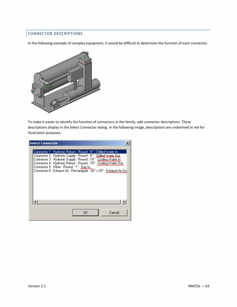
CONNECTOR DESCRIPTIONS
In the following example of complex equipment, it would be difficult to determine the function of each connector.
To make it easier to identify the function of connectors in the family, add connector descriptions. These descriptions display in the Select Connector dialog. In the following image, descriptions are underlined in red for illustration purposes.
Version 2.1 RMCSG — 63
SECTION 3: TESTING GUIDELINES To ensure the quality of Revit family content, thoroughly test families before using them in production or sharing them on Autodesk Seek. Test families with the guidelines in this section to:
• verify that new family content meets Autodesk standards
• ensure family parametric relationships
• ensure a consistent user experience
Two sets of testing guidelines are included: general guidelines and family‐specific guidelines:
• Use the general family testing guidelines to test all families.
• Use the family‐specific testing guidelines to test specific criteria per family type.
In addition, category‐specific testing guidelines are available for some family categories. These documents contain specific testing guidelines that you should use when available. Before testing a family, determine whether a category‐specific document has been published for the category of the family that you are testing.
RMCSG — 64 Version 2.1
3.1 GENERAL FAMILY TESTING GUIDELINES
Perform general testing on a family when it is:
• open in the Family Editor
• loaded into a project
Use the criteria in the checklists below to test families in each of the above environments. When testing families in projects, it is strongly recommended that you:
• Test families in projects created with the generic metric and imperial testing template projects that were included in the download package.
• Test families in projects that match the design intent of the family. For example, test a window family that is designed to be placed in a large commercial building in a large commercial project.
• Content that is designed to work in more than one Revit discipline must be tested in all applicable disciplines. For example, for a lighting fixture, test the connectors in Revit MEP, and verify that the fixture casts light as expected when rendering in Revit Architecture.
TIP: For large content creation projects, it is recommended that “spot checking” or random testing of 10% of the content be performed by a tester who is not the content creator.
FAMILY EDITOR TESTING CRITERIA
R Test all family parameters to ensure that the geometry flexes/adjusts correctly when the family parameters are modified.
R Test all family types – change the type, apply it, and inspect the geometry to verify that the dimensions and relationships are maintained.
R In a host‐based family, verify that the host flexes as expected. Change the host thickness and ensure that the family geometry adjusts appropriately.
R Verify that the family preview image is using the Preview view.
R Check all views to ensure that the family displays appropriately in different detail levels and when different Model Graphics styles are applied.
R Test constraints: o Test the handles on the edge of the geometry and make sure that all geometry is constrained to
either a reference plane or a reference line. o Test the dimension parameter to make sure that the reference plane or line is being adjusted by
the parameter and not the actual geometry.
Version 2.1 RMCSG — 65
PROJECT TESTING CRITERIA FOR REVIT ARCHITECTURE
R Using a test project or one of the testing template projects available for download, load the family in a project environment, and check all views for anomalies. If the family includes a type catalog, use it to load the family.
R Inspect the family appearance in all views (plan, reflected ceiling plan, elevation, Section, 3D) at all detail levels (Coarse, Medium, Fine).
R Inspect the family appearance in different Model Graphics Styles: Wireframe, Hidden Line, Shading, and Shading with Edges.
R Test all family types – change the type, apply it, and inspect the geometry to verify that the dimensions and relationships are maintained.
R Create new types and modify all parameters, checking all views for anomalies.
R Modify all material assignments to verify that materials are associated to the geometry correctly. TIP: To better inspect family geometry, modify all material type parameters to glass. Also, if any of the family geometry does not display as glass, then a material parameter is assigned incorrectly.
R Modify category and subcategory materials to verify the family is not using material type parameters.
R For hosted families:
R Place hosted families into the provided host thicknesses and confirm families work in all hosts appropriate to the families use, including in‐place walls and mass elements.
R Modify the host thickness by 25% ‐ 400%, and check for unconnected geometry and/or plan representations that may be disconnected from the geometry.
R Re‐inspect the family appearance in all views to ensure that the geometry displays as expected.
R Dimension to all references and snap all references to walls.
R Create a test rendering.
R Test the following commands on geometry created in the family:
R Copy/Paste
R Rotate
R Mirror
R Verify that the family preview image is using the Preview view.
R Test the family in an actual project, verify its performance, and ensure that the project matches the design intent of the family.
RMCSG — 66 Version 2.1
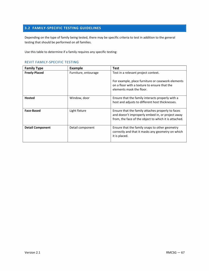
Version 2.1 RMCSG — 67
3.2 FAMILY‐SPECIFIC TESTING GUIDELINES
Depending on the type of family being tested, there may be specific criteria to test in addition to the general testing that should be performed on all families. Use this table to determine if a family requires any specific testing:
REVIT FAMILY‐SPECIFIC TESTING
Family Type Example Test Freely‐Placed Furniture, entourage Test in a relevant project context.
For example, place furniture or casework elements on a floor with a texture to ensure that the elements mask the floor.
Hosted Window, door Ensure that the family interacts properly with a host and adjusts to different host thicknesses.
Face‐Based Light fixture Ensure that the family attaches properly to faces and doesn’t improperly embed in, or project away from, the face of the object to which it is attached.
Detail Component Detail component Ensure that the family snaps to other geometry correctly and that it masks any geometry on which it is placed.