REVISION SW-508 - Iowa Department of TransportationConcrete Fillet', and modified circle notes....
2
place bond breaker Trowel smooth and place bond breaker Trowel smooth and 12'' 6'' 6'' 1 Back of Curb 8'' 4'' 6'' 6'' 1 4'' 4'' 6'' 8'' 3'' 3'' 8'' 18'' 8'' 4t2 4t3 4t1 4i1 4i1 4t1 6010 . 508 F I GURE (36'' typ., 18'' min.) Width of Insert Standard Curb Face of 6'' min. 5'' 2 : 1 Grade Form Slope Pavement Normal (if applicable) Edge of Gutter '' 2 1 1 '' 4 3 '' 2 1 '' 2 1 S H EET 1 O F 2 12'' 6'' 6'' 1 Back of Curb 8'' 4'' 6'' 6'' 1 4'' 4'' 8'' 3'' 8'' 18'' 8'' 4t2 4t3 4t1 4i1 4i1 4t1 (36'' typ., 18'' min.) Width of Insert min. 5'' 2 : 1 Grade Form Slope Pavement Normal (if applicable) Edge of Gutter '' 2 1 '' 2 1 5" '' 2 1 2'' Sloped Curb Face of 4'' 1 (6 Inch Standard Curb) INSERT (4 Inch Sloped Curb) INSERT inch. 2 1 reduce dimensions indicated by less than 36 inches. For an 18 inch insert, Insert shaping may be modified for insert widths 8" SW-508 REVISION 04-17-18 SHEET 1 of 2 REVISIONS: 'Concrete Fillet', and modified circle notes. Added second insert drawing to include 4" curb, changed 'Invert' callout to 3 INTAKE, LARGE BOX SINGLE OPEN-THROAT CURB STANDARD PLAN ROAD FIGURE 6010.508 SUDAS DIRECTOR DESIGN METHODS ENGINEER
Transcript of REVISION SW-508 - Iowa Department of TransportationConcrete Fillet', and modified circle notes....

place bond breaker
Trowel smooth and
place bond breaker
Trowel smooth and
12''6'' 6''
1
Back of Curb
8''
4''
6''6''
1
4''
4''
6''
8''
3''
3''
8''
18''
8''
4t2 4t3 4t1
4i14i1
4t1
6010.5
08
FIG
UR
E
(36'' typ., 18'' min.)
Width of Insert
Standard Curb
Face of 6''
min.5''
2:1
Grade
Form
Slope
Pavement
Normal
(if applicable)
Edge of Gutter
''21
1 ''43 ''2
1
''21
SHEET 1 O
F 2
12''6'' 6''
1
Back of Curb
8''
4''
6''6''
1
4''
4''
8''
3''
8''
18''
8''
4t2 4t3 4t1
4i1
4i1
4t1
(36'' typ., 18'' min.)
Width of Insert
min.5''
2:1
Grade
Form
Slope
Pavement
Normal
(if applicable)
Edge of Gutter
''21
''21
5"
''21
2''
Sloped Curb
Face of 4''
1
(6 Inch Standard Curb)INSERT
(4 Inch Sloped Curb)INSERT
inch.21
reduce dimensions indicated by
less than 36 inches. For an 18 inch insert,
Insert shaping may be modified for insert widths
8"
SW-508
REVISION
04-17-18
SHEET 1 of 2
REVISIONS:'Concrete Fillet', and modified circle notes.Added second insert drawing to include 4" curb, changed 'Invert' callout to
3
INTAKE, LARGE BOX
SINGLE OPEN-THROAT CURB
STANDARD PLANROADFIGURE 6010.508
SUDAS DIRECTOR DESIGN METHODS ENGINEER
REINFORCING BAR LIST
Mark Size Location Shape Count Length Spacing
MAXIMUM PIPE DIAMETERS
SHEET 2 OF 2
6010.5
08
FIG
UR
E
36''
Structure
Cast-in-place
30''
Structure
Precast
4w3
4w2
4w1
4i1
4b2
4b1
4t3
4t2
4t1
4
4
4
4
4
4
4
4
4
Walls
Walls
Walls
Insert
Base
Base
Top
Top
Top
4'-8''
4'-8''
Wall Height minus 4''
Boxout Length minus 8''
4'-6''
4'-6''
1'-10''
4'-6''
4'-8''
Varies
Varies
16
4
6
6
10
4
7
12''
12''
14''
See Plan
11''
11''
6''
12''
See Insert
Boxout Length
4'-0''
3''
5'-0''
4'-0'' 6''6''
18'' min.
36'' typ. Flow
10''
4'-0'' min.
6''
4t3
4''
Back of Curb
2
4
PLAN
12'' typ.
4t2
4t1
4t2
(Back of Curb)
Location Station
4'-0'' min. at Low Point
2'-0'' min. on Grade
'E' Joint
(typ.)
Dowel Bar
4i1
Insert
4t1
'E' Joint
'ED' Joint
4i1
'B' Joint
'ED' Joint'' Radius4
1Edge to
(11'-0'' min., 20'-0'' max.)
8''
Form Grade
22"
5'-0''
2
TYPICAL SECTION
6'' min.
12'' min.
3
Casting
Type G
SW-602
6'' 26''
4t1
Joint (typ.)
Construction
Optional
10'-0'' max.
Depth
Height
Wall Height
Wall
Lowest
Flowline
8'' min.
4'-0'' 6''
Back of Curb
4b1 4b2
4w1
4w2
FilletConcrete
6''
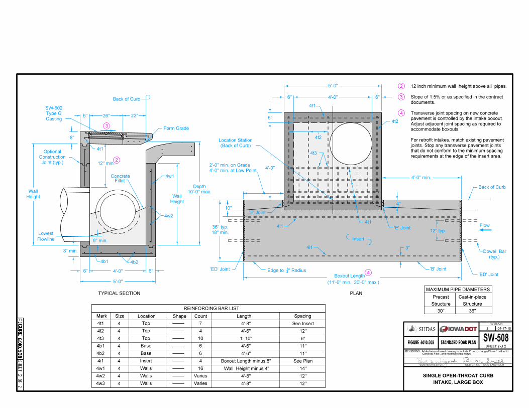
requirements at the edge of the insert area.
that do not conform to the minimum spacing
joints. Stop any transverse pavement joints
For retrofit intakes, match existing pavement
accommodate boxouts.
Adjust adjacent joint spacing as required to
pavement is controlled by the intake boxout.
Transverse joint spacing on new concrete
documents.
Slope of 1.5% or as specified in the contract
12 inch minimum wall height above all pipes.
3
4
SW-508
REVISION
04-17-18
SHEET 2 of 2
REVISIONS:'Concrete Fillet', and modified circle notes.Added second insert drawing to include 4" curb, changed 'Invert' callout to
3
INTAKE, LARGE BOX
SINGLE OPEN-THROAT CURB
STANDARD PLANROADFIGURE 6010.508
SUDAS DIRECTOR DESIGN METHODS ENGINEER