
Regulatory Guide 1.21, Revision 2, Measuring, Evaluating, and ...
U.S. NUCLEAR REGULATORY COMMISSION Revision 1 January 1999
REGULATORY GUIDE OFFICE OF NUCLEAR REGULATORY RESEARCH
REGULATORY GUIDE 3.54 (Draft was issued as DG-301 0)
SPENT FUEL HEAT GENERATION IN AN INDEPENDENT SPENT FUEL STORAGE INSTALLATION
A. INTRODUCTION
In 10 CFR Part 72, "Licensing Requirements for the Independent Storage of Spent Nuclear Fuel and HighLevel Radioactive Waste," paragraph (h)(1) of Section 72.122, "Overall Requirements," requires that spent fuel cladding be protected during storage against degradation that leads to gross ruptures or the fuel must be otherwise confined such that degradation of the fuel during storage will not pose operational safety problems with respect to its removal from storage. It
K>j has been shown that, under certain environmental conditions, high storage temperatures can cause degradation and gross rupture of the fuel rods to occur very rapidly. It is necessary to know what storage temperatures are anticipated during the life of the storage installation and that these temperatures will not significantly degrade the cladding to a point that causes gross ruptures. The temperature in an independent spent fuel storage installation is a function of the heat generated by the stored fuel assemblies. The spent fuel storage system is required by 10 CFR 72.128(a)(4) to be designed with a heat removal capability consistent with its importance to safety.
This regulatory guide presents a method acceptable to the Nuclear Regulatory Commission (NRC) staff for calculating heat generation rates for use as design, input for an independent spent fuel storage installation. The original guide, issued in September 1984, was based on validated analyses performed for pressurized-water reactors (PWRs), and boiling-water reactors (BWRs) were considered only as a simple conservative extension of the PWR data base. In this revision, the procedure for determining heat generation rates for both PWRs and BWRs is based on analyses of each reactor type using calculational methods that have been validated against measured heat generation data from PWR and BWR assemblies.
This revision presents a methodology that is simpler and is therefore expected to be more useful to applicants and reviewers.
This regulatory guide contains no information collection requirements and therefore is not subject to the requirements of the Paperwork Reduction Act of 1980 (44 U.S.C. 3501 et seq.).
USNRC REGULATORY GUIDES The guides are Issued ki the following ten broad divisions:
Regulatory Guides awe Issued to describe and make available to the public such infomiation as methods acceptable to the NRC staff for implementing specific parts of the 1. Power Reactors 6. Products
Commission's regulations, techniques used by the staff In evaluating specific problems or 2. Research and Test reactors 7. Transportation
postulated accidents, and data needed by the NRC staff in its review of applications for & Fuels and Materials Facitltes 8. Occupational Health
permits and licenses. Regulatory guides are not substitutes for regulations. and compli- 4. Environmental and Siting 9. Antitrust and Financial Review
ance with them Is not required. Methods and solutions different from those set out In the 5. Materials and Plant Protection 10. General
guides will be acceptable iN they provide a basis for the findings requisite to the Issuance of continuance of a permit or license by the Commission.
Single copies of regulatory guides may be obtained free of charge by writing the Reproduc
This guide was issued after consideration of comments received from the public. Corn- tion and Distribution Services Section, Office of the Chief Information Officer. U.S. Nuclear ments and suggestions for Inprovements In these guides are encouraged at al times, and Regulatory Commission. Washington, DC 20555-0001; or by fax at (310)415-2289;, or by guides will be revised, as appropriate, to accommodate comments and to reflect new infor- e-mail to [email protected]. mation or experience.
Issued guides may also be purchased from the National Technical Information Service on
Written comments may be submitted to the Rules and Directives Branch, ADM, U.S. Nuclear a standing order basis. Details on this service may be obtained by writing NTIS, 5285 Port Regulatory Commission, Washington, DC 20555-0001. Royal Road. Springfield, VA 22161.
J
B. DISCUSSION
The methodology of NUREG/CR-5625 1 is appropriate for computing the heat generation rates of fuel assemblies from light-water-cooled power reactors as a function of burnup, specific power, and decay time. The computed heat generation results are used in the next section in a procedure for determining heat generation rates for PWR and BWR assemblies.
Calculations of decay heat have been verified by comparison with the existing data base of experimentally measured decay heat rates for PWR and BWR spent fuel. The range of parameter values in the procedure is considered to lie in the mainstream of typical burnup, specific power, enrichment, and cooling time. A detailed example is shown in Appendix A.
The following terms and units have been used in
this guide.
TERMS AND UNITS USED IN GUIDE
Be - bumup in last cycle, MWd/kgU Be-. - burnup in next-to-last cycle, MWd/kgU Bi - fuel bumup increase for cycle i, MWd/kgU Btot - total bumup of discharged fuel, MWd/kgU E, - initial fuel enrichment, wt-% 235U P - specific power of fuel as in Equations 2 and 3,
kW/kgU P•n - average cumulative specific power during 80%
uptime, kW/kgU Paoe-l - average cumulative specific power (at 80%)
through cycle e-1, the next-to-last cycle Pe - fuel-specific power during the last cycle e Pe-• - fuel-specific power during cycle e-1, the next
to-last cycle PL, PH - lower and higher values of specific power that
bracket the specific power value of Pav, Plab - heat generation rate that is obtained from the
table by interpolation between the lower and higher bracketing values
Pyu• - final heat generation rate determined by applying all adjustment factors, followed by the safety factor to the value Ptb
TL, TH - lower and higher time values in a table that bracket the cooling time of interest, Tc
'Technical Support for a Proposed Decay Heat Guide Using SAS2H/ ORIGEN-S Data, NUREG/CR-5625 (ORNL-6698), September 1994. Copies are available for inspection or copying for a fee from the NRC Public Document Room at 2120 L Street NW., Washington, DC; the PDR's mailing address is Mail Stop LL-6, Washington, DC 20555; telephone (202) 634-3273; fax (202) 634-3343. Copies may be purchased at current rates from the U.S. Government Printing Office, P.O. Box 37082, Washington, DC 20402-9328 [telephone (202) 512-1800]; or from the National Technical Information Service by writing NTIS at Port Royal Road, Springfield, VA 22161.
S - percentage safety factor applied to decay heat rates, Plab
Tc - cooling time of an assembly, in years T1 - cycle time of last cycle before discharge, in days Te-1 - cycle time of next-to-last cycle, in days T - cycle time of ith reactor operating cycle,
including downtime for all but last cycle of assembly history, in days
7r. - reactor residence time of assembly, from first loading to shutdown for discharge, in days
f7 - last-cycle short cooling time modification factor f'7 - next-to-last cycle short cooling time factor fe - 23SJ initial enrichment modification factor fp - excess power adjustment factor p - heat generation rate of spent fuel assembly,
W/kgU
C. REGULATORY POSITION
The following method for determining heat generation rates of reactor spent fuel assemblies is acceptable to the NRC staff. There may be fuel assemblies with characteristics that are sufficiently outside the mainstream of typical operations that they need a separate computation of the heat generation rate. A discussion of the characteristics of assumed typical reactor operations is given in Appendix B.
The first part of this section contains the definitions and derivations, as used in this guide, of parameters needed in the determination of the heat generation rate of a fuel assembly. The second part contains the procedure used in deriving the final heat rate of an assembly. Although allowance has been made to use simple adjustment factors for cases that are somewhat atypical, many cases will probably not require any adjustment of the table heat rate other than the safety factor.
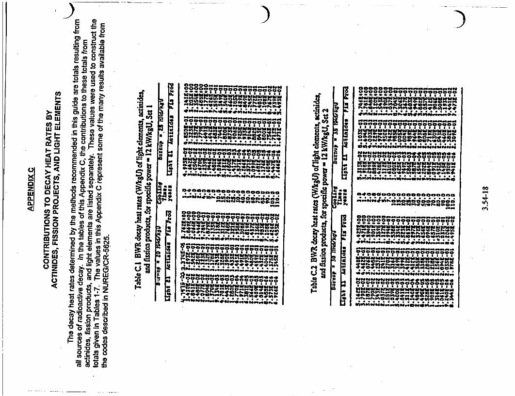
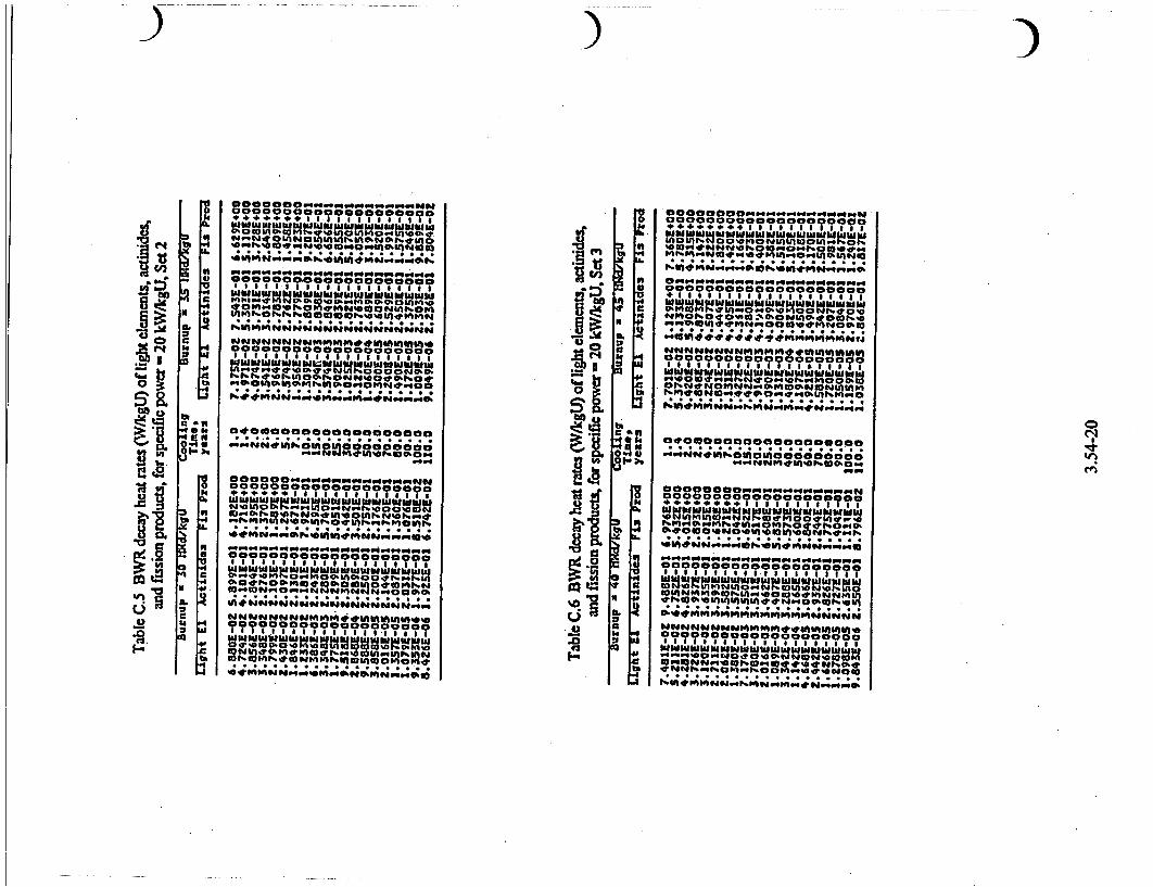
Heat generation rate tables for actinides, fission products, and light elements are given in Appendix C for informational purposes only. They are not used directly in this guide's method for determining heat rates.
1. DEFINITIONS AND DERIVATIONS OF PARAMETERS
The following definitions and derivations of parameters of the spent fuel assembly are used in the procedure in this guide.
1.1 Heat Generation Rate (p)
The heat generation rate of the spent fuel assembly is the recoverable thermal energy (from radioactive decay) of the assembly per unit time per unit fuel mass.
3.54-2
The units for heat generation rate used in this guide are watts per kilogram U (W/kgU), where U is the initial uranium loaded. Heat generation rate has also been referred to as decay heat rate, afterbeat, or afterheat power.
1.2 Cycle and Cycle Times (T,)
A cycle of the operating history for a fuel assembly is, with one exception, the duration between the time criticality is obtained for the initially loaded or reloaded reactor to the time at which the next reloaded core becomes critical. The exception is for the last cycle, in which the cycle ends with the last reactor shutdown before discharge of the assembly. T. denotes the elapsed time during cycle i for the assembly. Specifically, the first and last cycles are denoted by i =
s (for start) and i = e (for end), respectively. T , the total residence time of the assembly, is the sum of all T, for i = s through e, inclusive. Except for the last cycle for an assembly, the cycle times include the downtimes during reload. Cycle times, in this guide, are in days.
1.3 Fuel Burnup of the Assembly (B, and B,)
The fuel burnup of cycle i, Be, is the recoverable thermal energy per unit fuel mass during the cycle in units of megawatt days per metric ton (tonne) initial uranium (MWd/tU), or in the SI unitse of mass used in
~ this guide, megawatt days per kilogram U (MWd/ kgU). Bi is the best maximum estimate of the fuel assembly bumup during cycle i. B,o, is the total operating history burnup:
Btot-=iB i=5
(Equation 1)
1.4 Specific Power of the Fuel (P., P,, P,,, and P,,.,)
Specific power has a unique meaning in this guide. The reason for developing this definition is to take into account the differences between the actual operating history of the assembly and that used in the computation of the tabulated heat generation rates. The calculational model applied an uptime (time at power) of 80% of the cycle time in all except the last cycle (of the discharged fuel assembly), which had no downtime. The definition of specific power, used here, has two basic characteristics. First, when the actual uptime experienced by the assembly exceeds the 80% applied in the SAS2H/ORIGEN-S calculations, the heat rate derived by the guide procedure maintains equivalent accuracies within 1%. Second, when the actual uptime experienced is lower than the 80% applied in the calculations, the heat rate is reduced.
2 The International System of Units.
The technical basis for these characteristics is presented in NUREG/CR-5625.
The specific power of cycle i, or e (last cycle), in kW/kgU, using bumup in MWd/kgU, is determined by:
1000B P 1 = Bfor i < e 0.8Th
(Equation 2)
10.0B= for I = e
The average specific power over the entire operating history of a fuel assembly, using the same units as in Equation 2, is determined by:
PIW. lOOOB, P.. = *-I
T.+o.8 E T, •l.
(Equation 3)
The average specific power through the next-tolast cycle is used in applying the adjustment factor for short cooling time (see Regulatory Position 2.2). This parameter is determined by:
1000 (Bw, - B,) 0- -- 0(T,,- T,)
(Equation 4)
Note that BM, and P ,, as derived here, are used in determining the heat generation rate with this guide. Also, for cooling times <7 years, Pe is used in an adjustment formula. The method applied here accommodates storing a fuel assembly outside the reactor during one or two cycles and returning it to the reactor. Then, B, = 0 may be set for all intermediate storage cycles. If the cooling time is short (i.e., _10 years), the results derived here may be excessively high for cases in which the fuel was temporarily discharged. Other evaluation methods that include the incorporation of storage cycles in the power history may be preferable.
1.5 Assembly Cooling Time (7T)
The cooling time, T, of an assembly is the time elapsed from the last downtine of the reactor prior to its discharge (at end of T) to the time at which the heat generation rate is desired. Cooling times, in this guide, are in years.
1.6 Assembly Initial Fuel Enrichment (E,)
The initial enrichment, E, of the fuel assembly is considered to be the average weight percent 2 35
U in the
3.54-3
uranium when it is first loaded into the reactor. Heat generation rates vary with initial enrichment for fuel having the same burnup and specific power; the heat rate increases with lower enrichment. If the enrichment is different from that used in the
*'c.alculations at a given burnup'and specific power, a correction factor is applied.
2. DETERMINATION OF HEAT GENERATION RATES
Directions for determining the heat generation rates of light-water-reactor (LWR) fuel assemblies from Tables 1 through 8 are given in this section. First, a heat rate, p,, is found by interpolation from Tables 1 through 3 or Tables 5 through 7. Next, a safety factor and all the necessary adjustment factors are applied to determine the final heat generation rate, P .- There are three adjustment factors (see Regulatory Pj,4ons 2.2 to 2.4) plus a safety factor (see Regulatory Position 2.5) that are applied in computing the final heat generation rate, Pp.,, fromp.,. In many cases, the adjustment factors are unity and thus are not needed. An alternative to these directions is the use of the light-water-reactor afterheat rate calculation (LWRARC) code on a personal computer; the code is referred to in Regulatory Position 2.7. This code evaluates pt andpn using the data and procedures established in this guide.
2.1 Computing Heat Rate Provided by Tables
Tables 1 through 3 are for BWR fuel, and Tables 5 through 7 are forPWR fuel. .The heat rates in each table pertain to a single average specific poWaand are listed as a function of total bumup and cooling time. After determining P , B., and T as above, select the next lower (L-index) and next higher (H-index) heat rate values from the tables so that:
and
P• P •v ePH BL•SB,. •5BHf
TL•T •TI
Compute pb, the heat generation rate, at P , B., and T, by proper interpolation between the tabuated values of heat rates at the lower and higher parameter limits. A linear interpolation should-beused between heat rates for either burnup or specific power interpolations. In computing the heat rate at T, the interpolation should be logarithmic in heat rate and linear in cooling time. Specifically, the interpolation formulas for interpolating in specific power, burnup, and cooling time are, respectively,
P PL + PLp -L)
P PL + PH-PL (Bt -EBL) PH - PB.
P. [-;- (to- rL BELT
(Equation 5)
(Equation 6)
(Equation 7)
Where PL and PH represent the tabulated or interpolated heat rates at the appropriate parameter limits corresponding to the L and H index. If applied in the sequence given above, Equation 5 would need to be used four times to obtain p values that correspond to B. and B at valups of T and T,. A mini-table. of four p valuesat 4P is now available to interpolate burnup and cooling time. Equation 6 would then be applied to obtain two values of p at TL and TH. One fmal interpolation of these two p values (at P, and B,o,) using Equation 7 is needed to calculate the final p, value corresponding to P , B , and T. The optional Lagrangian interpolation scheme offered by the LWRARC code is also considered an acceptable method for interpolating the decay heat data.
If P. or B,, falls below the minimum table value range, the minimum table-specific power or burnup, respectively, may be used conservatively. If P exceefls the maximum table value, the table with the maximum-specific power (Table 3 for BWR fuel and Table 7 for PWR fuel) may be used in addition to the adjustment factor, fp, described in Regulatory Position 2.3.
The tables should not be applied if B, exceeds the maximum burnup in the tables, or if T is less than the minimum (1 year). If T exceeds the maximum (110 years) cooling time of the tables, the 1 10-year value is acceptable, although it may be too conservative.
2.2 Short Cooling Time Factorsf7 andf'7
The heat rates presented in Tables 1 through 3 and Tables 5 through 7 were computed from operating histories in which a constant specific power and an uptime of 80% of the cycle time were applied. Expected variations from these assumptions cause only minor changes (51 %) in decay heat rates beyond approximately 7 years of cooling. However, if the specific power near the end of the operating history is
3.54-4
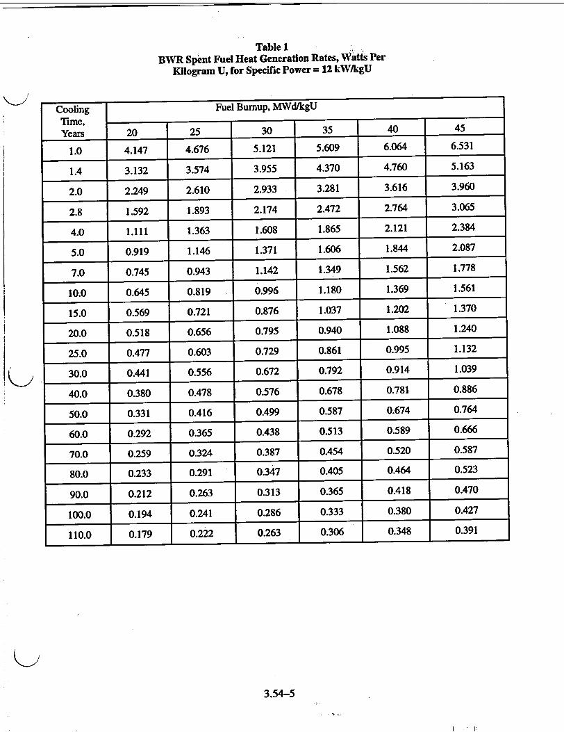
Table I BWR Spent Fuel Heat Generation Rates, Watts Per
Kilogram U, for Specific Power = 12 kW/kgU
Cooling Fuel Burnup, MWd/kgU
Time, Years 20 25 30 35 40 45
1.0 4.147 4.676 5.121 5.609 6.064 6.531
1.4 3.132 3.574 3.955 4.370 4.760 5.163
2.0 2.249 2.610 2.933 3.281 3.616 3.960
2.8 1.592 1.893 2.174 2.472 2.764 3.065
4.0 1.111 1.363 1.608 1.865 2.121 2.384
5.0 0.919 1.146 1.371 1.606 1.844 2.087
7.0 0.745 0.943 1.142 1.349 1.562 1.778
10.0 0.645 0.819 0.996 1.180 1.369 1.561
15.0 0.569 0.721 0.876 1.037 1.202 1.370
20.0 0.518 0.656 0.795 0.940 1.088 1.240
25.0 0.477 0.603 0.729 0.861 0.995 1.132
30.0 0.441 0.556 0.672 0.792 0.914 1.039
40.0 0.380 0.478 0.576 0.678 0.781 0.886
50.0 0.331 0.416 0.499 0.587 0.674 0.764
60.0 0.292 0.365 0.438 0.513 0.589 0.666
70.0 0.259 0.324 0.387 0.454 0.520 0.587
80.0 0.233 0.291 0.347 0.405 0.464 0.523
90.0 0.212 0.263 0.313 0.365 0.418 0.470
100.0 0.194 0.241 0.286 0.333 0.380 0.427
110.0 0.179 0.222 0.263 0.306 0.348 0.391
3.54-5
I . .1
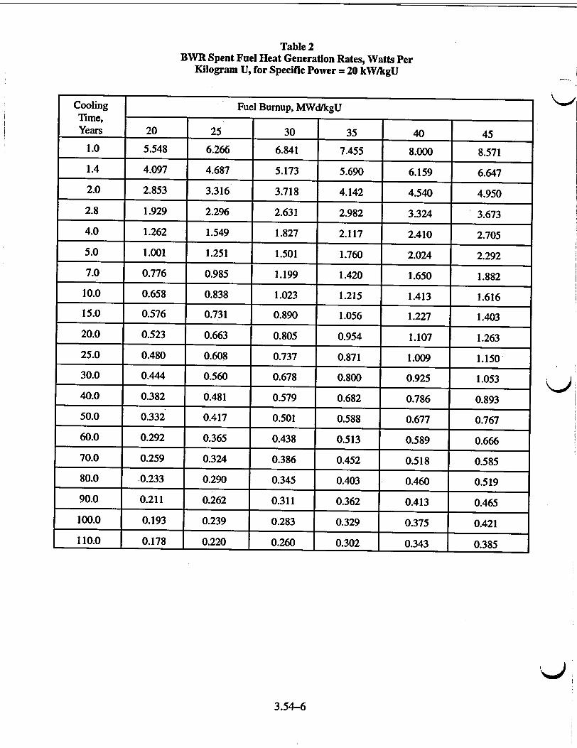
Table 2 BWR Spent Fuel Heat Generation Rates, Watts Per
Kilogram U, for Specific Power = 20 kW/kgU
Cooling Fuel Bumup, MWd/kgU Time, Years 20 25 30 35 40 45
1.0 5.548 6.266 6.841 7.455 8.000 8.571
1.4 4.097 4.687 5.173 5.690 6.159 6.647
2.0 2.853 3.316 3.718 4.142 4.540 4.950
2.8 1.929 2.296 2.631 2.982 3.324 3.673
4.0 1.262 1.549 1.827 2.117 2.410 2.705
5.0 1.001 1.251 1.501 1.760 2.024 2.292
7.0 0.776 0.985 1.199 1.420 1.650 1.882
10.0 0.658 0.838 1.023 1.215 1.413 1.616
15.0 0.576 0.731 0.890 1.056 1.227 1.403
20.0 0.523 0.663 0.805 0.954 1.107 1.263
25.0 0.480 0.608 0.737 0.871 1.009 1.150
30.0 0.444 0.560 0.678 0.800 0.925 1.053
40.0 0.382 0.481 0.579 0.682 0.786 0.893
50.0 0.332 0.417 0.501 0.588 0.677 0.767
60.0 0.292 0.365 0.438 0.513 0.589 0.666
70.0 0.259 0.324 0.386 0.452 0.518 0.585
80.0 0.233 0.290 0.345 0.403 0.460 0.519
90.0 0.211 0.262 0.311 0.362 0.413 0.465
100.0 0.193 0.239 0.283 0.329 0.375 0.421
110.0 0.178 0.220 0.260 0.302 0.343 0.385
Q143.54-6
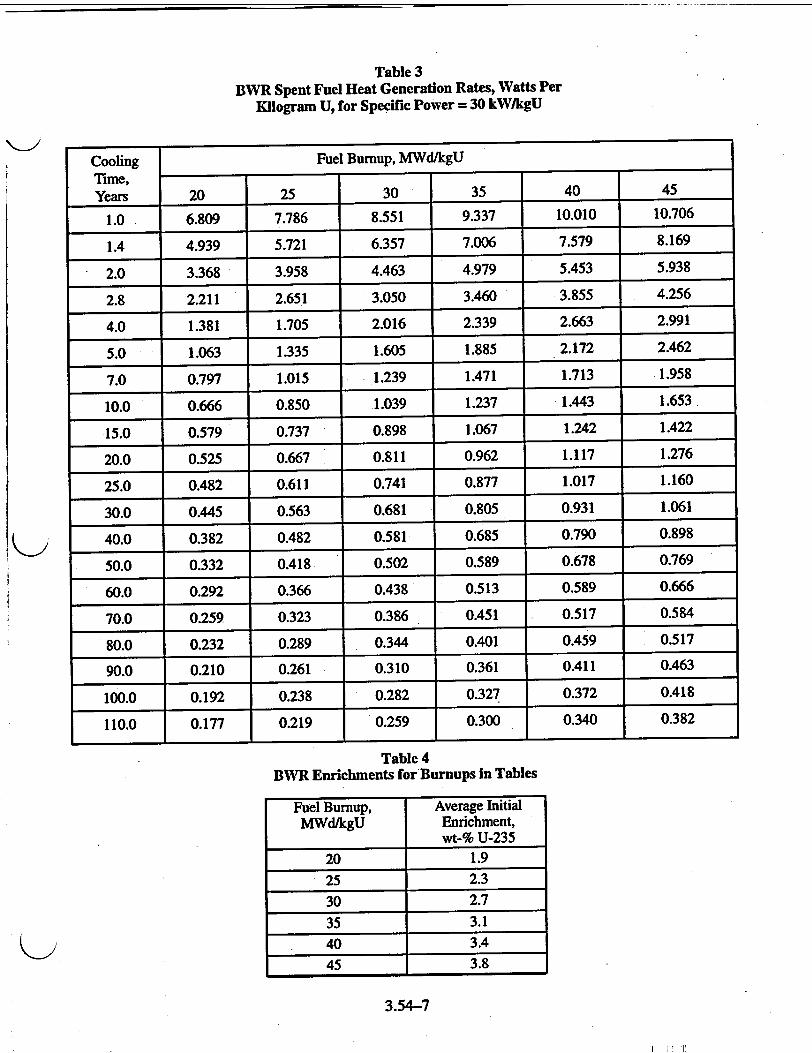
Table 3 BWR Spent Fuel Heat Generation Rates, Watts Per
Kilogram U, for Specific Power = 30 kW/kgU
Cooling Fuel Bumup, MWd/kgU Time, Years 20 25 30 35 40 45
1.0 6.809 7.786 8.551 9.337 10.010 10.706
1.4 4.939 5.721 6.357 7.006 7.579 8.169
2.0 3.368 3.958 4.463 4.979 5.453 5.938
2.8 2.211 2.651 3.050 3.460 3.855 4.256
4.0 1.381 1.705 2.016 2.339 2.663 2.991
5.0 1.063 1.335 1.605 1.885 2.172 2.462
7.0 0.797 1.015 1.239 1.471 1.713 1.958
10.0 0.666 0.850 1.039 1.237 1.443 1.653
-15.0 0.579 0.737 0.898 1.067 1.242 1.422
20.0 0.525 0.667 0.811 0.962 1.117 1.276
25.0 0.482 0.611 0.741 0.877 1.017 1.160
30.0 0.445 0.563 0.681 0.805 0.931 1.061
40.0 0.382 0.482 0.581 0.685 0.790 0.898
50.0 0.332 0.418 0.502 0.589 0.678 0.769
60.0 0.292 0.366 0.438 0.513 0.589 0.666
70.0 0.259 0.323 0.386 0.451 0.517 0.584
80.0 0.232 0.289 0.344 0.401 0.459 0.517
90.0 0.210 0.261 0.310 0.361 0.411 0.463
100.0 0.192 0.238 0.282 0.327 0.372 0.418
110.0 0.177 0.219 0.259 0.300 0.340 0.382
Table 4 BWR Enrichments for'Burnups In Tables
Fuel Burnup, Average Initial MWd/kgU Enrichment,
wt-% U-235 20 1.9
25 2.3
30 2.7
35 3.1
40 3.4
45 3.8
3.54-7
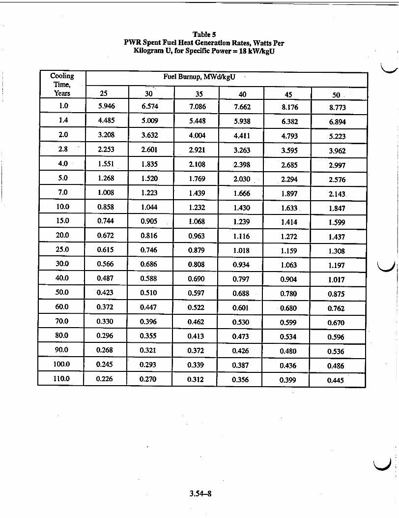
Table 5 PWR Spent Fuel Heat Generation Rates, Watts Per
Kilogram U, for Specific Power = 18 kW/kgU
Cooling Fuel Burnup, MWd/kgU Time, Years 25 30 35 40 45 50
1.0 5.946 6.574 7.086 7.662 8.176 8.773
1.4 4.485 5.009 5.448 5.938 6.382 6.894
2.0 3.208 3.632 4.004 4.411 4.793 5.223
2.8 2.253 2.601 2.921 3.263 3.595 3.962
4.0 1.551 1.835 2.108 2.398 2.685 2.997
5.0 1.268 1,520 1.769 2.030 2.294 2.576
7.0 1.008 1.223 1.439 1.666 1.897 2.143
10.0 0.858 1.044 1.232 1.430 1.633 1.847
15.0 0.744 0.905 1.068 1.239 1.414 1.599
20.0 0.672 0.816 0.963 1.116 1.272 1.437
25.0 0.615 0.746 0.879 1.018 1.159 1.308
30.0 0.566 0.686 0.808 0.934 1.063 1.197
40.0 0.487 0.588 0.690 0.797 0.904 1.017
50.0 0.423 0.510 0.597 0.688 0.780 0.875
60.0 0.372 0.447 0.522 0.601 0.680 0.762
70.0 0.330 0.396 0.462 0.530 0.599 0.670
80.0 0.296 0.355 0.413 0.473 0.534 0.596
90.0 0.268 0.321 0.372 0.426 0.480 0.536
100.0 0.245 0.293 0.339 0.387 0.436 0.486
110.0 0.226 0.270 0.312 0.356 0.399 0.445
3.54-8
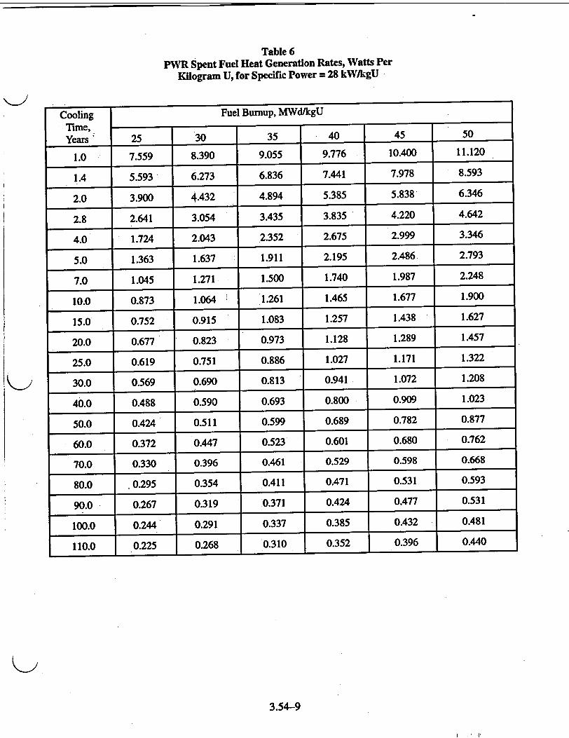
Table 6 PWR Spent Fuel Heat Generation Rates, Watts Per
Kilogram U, for Specific Power = 28 kW/kgU
Cooling Fuel Bumup, MWd/kgU
Time, Years 25 30 35 40 45 50
1.0 7.559 8.390 9.055 9.776 10.400 11.120
1.4 5.593 6.273 6.836 7.441 7.978 8.593
2.0 3.900 4.432 4.894 5.385 5.838 6.346
2.8 2.641 3.054 3.435 3.835 4.220 4.642
4.0 1.724 2.043 2.352 2.675 2.999 3.346
5.0 1.363 1.637 1.911 2.195 2.486 2.793
7.0 1.045 1.271 1.500 1.740 1.987 2.248
10.0 0.873 1.064 1.261 1.465 1.677 1.900
15.0 0.752 0.915 1.083 1.257 1.438 1.627
20.0 0.677 0.823 0.973 1.128 1.289 1.457
25.0 0.619 0.751 0.886 1.027 1.171 1.322
30.0 0.569 0.690 0.813 0.941 1.072 1.208
40.0 0.488 0.590 0.693 0.800 0.909 1.023
50.0 0.424 0.511 0.599 0.689 0.782 0.877
60.0 0.372 0.447 0.523 0.601 0.680 0.762
70.0 0.330 0.396 0.461 0.529 0.598 0.668
80.0 .0.295 0.354 0.411 0.471 0.531 0.593
90.0 0.267 0.319 0.371 0.424 0.477 0.531
100.0 0.244 0.291 0.337 0.385 0.432 0.481
110.0 0.225 0.268 0.310 0.352 0.396 0.440
3.54-9
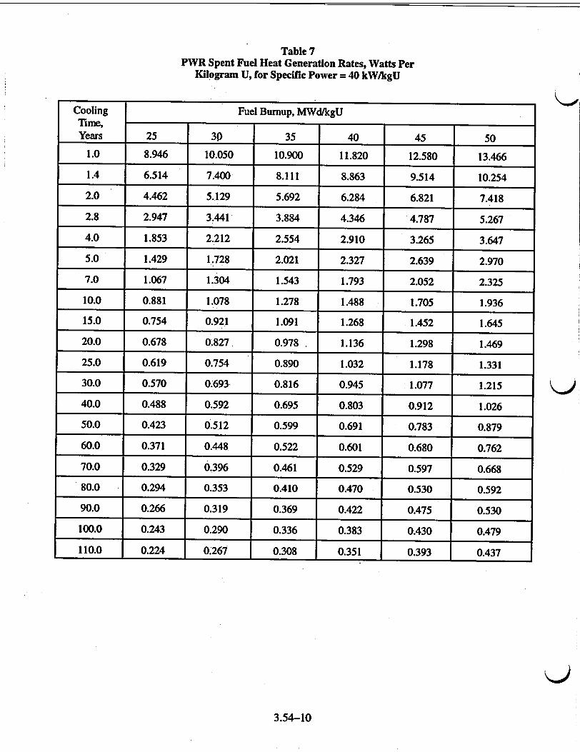
Table 7 PWR Spent Fuel Heat Generation Rates, Watts Per
Kilogram U, for Specific Power = 40 kW/kgU
Cooling Fuel Burnup, MWd/kgU Time, Years 25 30 35 40 45 50
1.0 8.946 10.050 10.900 11.820 12.580 13.466
1.4 6.514 7.400 8.111 8.863 9.514 10.254
2.0 4.462 5.129 5.692 6.284 6.821 7.418
2.8 2.947 3441 3.884 4.346 4.787 5.267
4.0 1.853 2.212 2.554 2.910 3.265 3.647
5.0 1.429 1,728 2.021 2.327 2.639 2.970
7.0 1.067 1.304 1.543 1.793 2.052 2.325
10.0 0.881 1.078 1.278 1.488 1.705 1.936
15.0 0.754 0.921 1.091 1.268 1.452 1.645
20.0 0.678 0.827 0.978 1.136 1.298 1.469
25.0 0.619 0.754 0.890 1.032 1.178 1.331
30.0 0.570 0.693 0.816 0.945 1.077 1.215
40.0 0.488 0.592 0.695 0.803 0.912 1.026
50.0 0.423 0.512 0.599 0.691 0.783 0.879
60.0 0.371 0.448 0.522 0.601 0.680 0.762
70.0 0.329 0.396 0.461 0.529 0.597 0.668
80.0 0.294 0.353 0.410 0.470 0.530 0.592
90.0 0.266 0.319 0.369 0.422 0.475 0.530
100.0 0.243 0.290 0.336 0.383 0.430 0.479
110.0 0.224 0.267 0.308 0.351 0.393 0.437
K)j
3.54-10
K)
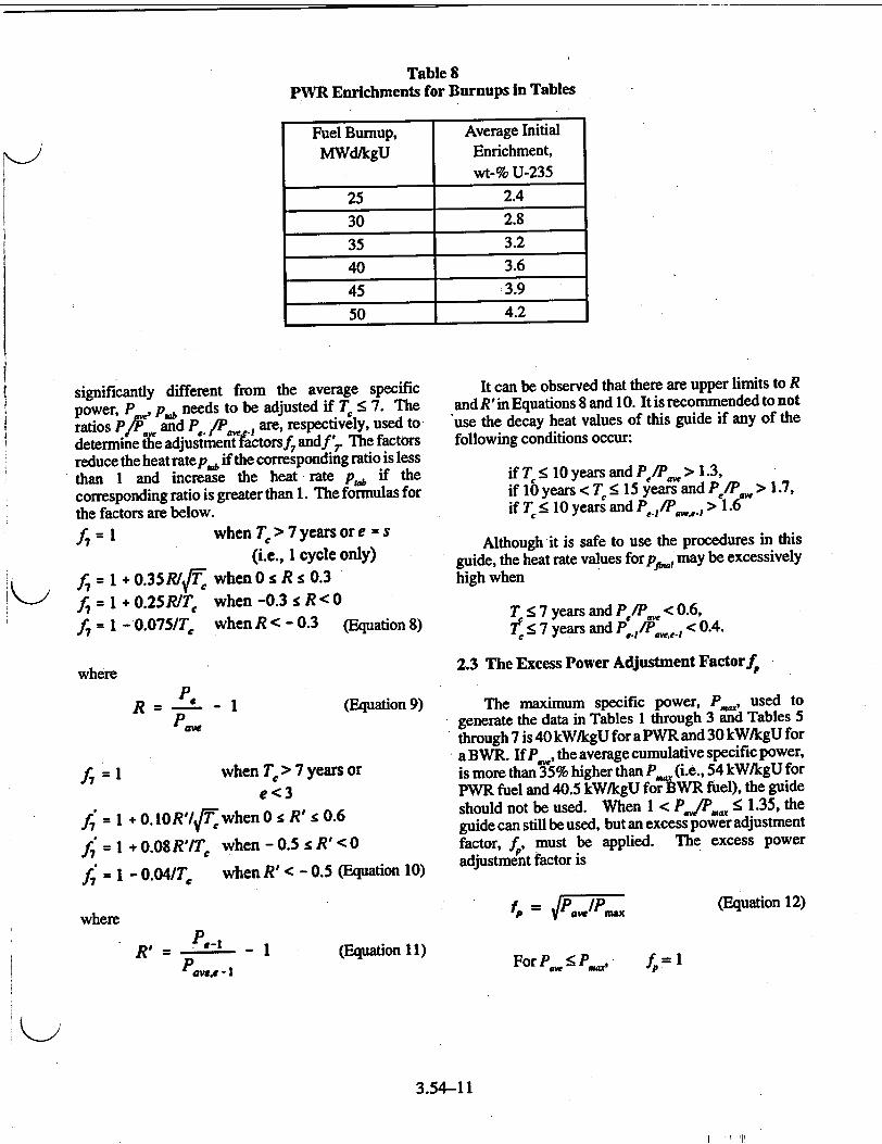
Table 8 PWR Enrichments for Burnups in Tables
Fuel Burnup, Average Initial
MWd/kgU Enrichment, wt-% U-235
25 2.4
30 2.8
35 3.2
40 3.6
45 3,9
50 4.2
significantly different from the average specific power, P ,•, p,1 needs to be adjusted if T < 7. The ratios Pf and P/P are, respectively, used to determine the adjustmenatictorsf 7 andf'> The factors reduce the heat rate pb, if the corresponding ratio is less than 1 and increase the heat rate p,., if the corresponding ratio is greater than 1. The formulas for the factors are below.
A = when T, > 7 years or e = s (i.e., I cycle only)
f 7 = 1 + 0.35RI1/ -when 0s R s 0.3
f = I + 0.25RIT' when -0.3 s R < 0
f= 1 - 0.075/T, when R < - 0.3 (Equation 8)
where
PW R = a--p - (Equation 9)
f7 = 1 when TC > 7 years or
e<3 r' = I +0.lOR'/.[T when0"f R' c0.6
f = I + 0.08 R'IT when - 0.5 : R' < 0
J = C - 0.04/TC
where
when R' < - 0.5 (Equation 10)
P,, R' PC-, -1
Pawx, - I(Equation 11)
It can be observed that there are upper limits to R and R'in Equations 8 and 10. It is recommended to not "use the decay heat values of this guide if any of the following conditions occur:
if T < 10 years and P/Pw > 1.3, if 10 years < T < 15 years and P/P > 1.7, if T < 10 years and P,,fý,., > 1.6
Although it is safe to use the procedures in this guide, the heat rate values forp• may be excessively
high when
T < 7 years and P/P• < 0.6,
T 5 7 years and Pe-/P.. < 0.4.
2.3 The Excess Power Adjustment Factorf,
The maximum specific power, P , used to generate the data in Tables 1 through 3 a Tables 5
through 7 is 40 kW/kgU for a PWR and 30 kWikgU for a BWR. If P , the average cumulative specific power, is more than 35% higher than P,. (i.e., 54 kW/kgU for PWR fuel and 40.5 kW/kgU for BWR fuel), the guide
should not be used. When 1 < P,,P.. < 1.35, the guide can still be used, but an excess power adjustment factor, f , must be applied. The excess power adjustment factor is
Fo= vP.,/P.mx
For P• •; P30=,
(Equation 12)
fP =1
3.54-11
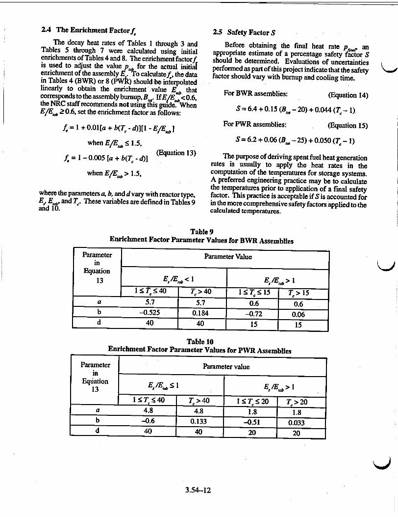
2.4 The Enrichment Factorf
The decay heat rates of Tables 1 through 3 and Tables 5 through 7 were calculated using initial enrichments of Tables 4 and 8. The enrichment factorf. is used to adjust the value p . for the actual initial enrichment of the assembly E . o calculatef , the data in Tables 4 (BWR) or 8 (PWk) should be interpolated linearly to obtain the enrichment value E.a that corresponds to the assembly burnup, B . IfE/E. < 0.6, the NRC staff recommends not using &is guide. When E/E• Ž 0.6, set the enrichment factor as follows:
.f= +0.01[a + b(T - d)][l - EIE,4]
when E!E,Ab< 1.5,
f,=1 - 0.005 [a + b(T- d) (Euation3)
when E/Eab > 1.5,
where the parameters a, b, and d vary with reactor type, Ee Eab, and K'. These variables are defined in Tables 9 and 10.
2.5 Safety Factor S
Before obtaining the final heat rate pa, an appropriate estimate of a percentage safety factor S should be determined. Evaluations of uncertainties performed as part of this project indicate that the safety factor should vary with burnup and cooling time.
For BWR assemblies: (Equation 14)
S= 6.4 + 0.15 (Bw - 20) + 0.044 (T,- 1)
For PWR assemblies: (Equation 15)
S = 6.2 + 0.06 (Bw - 25) + 0.050 (T - 1)
The purpose of deriving spent fuel heat generation rates is usually to apply the heat rates in the computation of the temperatures for storage systems. A preferred engineering practice may be to calculate the temperatures prior to application of a final safety factor. This practice is acceptable ifS is accounted for in the more comprehensive safety factors applied to the calculated temperatures.
Table 9 Enrichment Factor Parameter Values for BWR Assemblies
Parameter Parameter Value in
Equation 13 E /E,, < 1 E,/E;b > 1
:1• <40 T>40 1 TK 15 K >15 a 5.7 5.7 0.6 0.6 b -0.525 0.184 -0.72 0.06 d 40 40 15 15
Table 10 Enrichment Factor Parameter Values for PWR Assemblies
Parameter Parameter value in
Equation EIE •1 EIE 13 E ab s tab >1
1l<T<540 T>40 1<T<K20 T >20 a 4.8 4.8 1.8 1.8 b -0.6 0.133 -0.51 0.033 d 40 1 40 20 20
3.54-12
2.6 Final Heat Generation Rate Evaluation
The equation for converting p,•, determined in Regulatory Position 2.1, to the final heat generation rate of the assembly, is
pft = (1 + 0.0S)f7 f 7 ffp," (Equation 16)
where fI f;. f, f,, and S are determined by the procedures given in Regulatory Positions 2.2 through 2.5.
2.7 Heat Rate Evaluation by LWRARC Code
The LWRARC (light-water-reactor afterheat rate calculation) code is an MS-DOS PC program that performs the calculations in this guide. The only input for cases in which the cooling time exceeds 15 years are Be T,,, E., and T. Additionally, the short cooling time factors require B' and T• of the last and next-to-last cycles. The code features a pull-down menu system with data entry screens containing context-sensitive
help messages and verification dialog boxes. The menus may be used with either a keyboard or a mouse. The code printout (one page per case) contains the input data, the computed safety and adjustment factors, and the interpolated and final computed decay heat rates. The output file may be printed, observed on a monitor, or saved. Input cases may be saved, retrieved, duplicated, or stacked in the input file.
The LWRARC code may be requested from the Radiation Safety Information Computational Center (RSICC).
Radiation Safety Information Computational Center
Oak Ridge National Laboratory P.O. Box 2008 Oak Ridge, TN 37831-6362 Telephone: (423)574-6176 FAX: (423)574-6182 Electronic Mail: PDCm1±gox
3.54-13
APPENDIX A
SAMPLE CASE USING HEAT GENERATION RATE TABLES
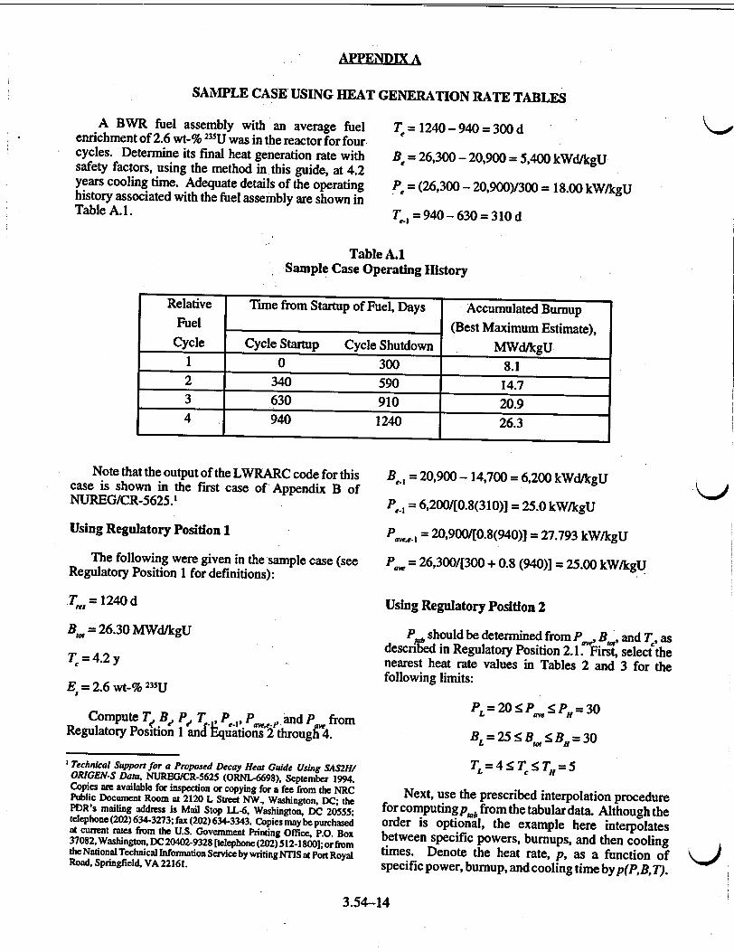
A BWR fuel assembly with an average fuel enrichment of 2.6 wt-% 235U was in the reactor for four cycles. Determine its final heat generation rate with safety factors, using the method in this guide, at 4.2 years cooling time. Adequate details of the operating history associated with the fuel assembly are shown in Table A.1.
T = 1240 - 940 = 300 d
Be = 26,300 - 20,900 = 5,400 kWd/kgU
p = (26,300 - 20,900)/300 = 18.00 kW/kgU
T 1= 940 - 630 = 310 d
Table A.1 Sample Case Operating History
Note that the output of the LWRARC code for this case is shown in the first case of Appendix B of NUREG/CR-5625.1
Using Regulatory Position 1
The following were given in the sample case (see Regulatory Position 1 for definitions):
T = 1240d
B,, = 26.30 MWd/kgU
T= 4.2 y
E = 2.6 wt-% 235U
Compute T B, P ,T, P PP,, and P from Regulatory Position 1 and Equations 2 through 4.
'Technical Support for a Proposed Decay Heat Guide Using SAS2H/ OPJGEN-S Data, NUREBG/CR-5625 (ORNL-6698), September 1994. Copies are available for inspection or copying for a fee from the NRC Public Document Room at 2120 L Street NW, Washington, DC; the PDR's mailing address is Mail Stop LL-6, Washington, DC 20555; telephone (202) 634-3273; fax (202) 634-3343. Copies may be purchased at current rates from the U.S. Government Printing Office, P.O. Box 37082, Washington, DC 20402-9328 [telephone (202) 5 12-1800]; or from the National Technical Information Service by writing NTIS at Port Royal Road, Springfield, VA 22161.
B,_l = 20,900 - 14,700 = 6,200 kWd/kgU
P., = 6,200/[0.8(310)] = 25.0 kW/kgU
P .a.1 = 20,900/[0.8(940)] = 27.793 kW/kgU
Paw = 26,300/[300 + 0.8 (940)] = 25.00 kW/kgU
Using Regulatory Position 2
P~b should be determined from P , B.0 and T, as described in Regulatory Position 2.1. First, select the nearest heat rate values in Tables 2 and 3 for the following limits:
PL = 20<Pa< f iPH 30
BE = 25 :< B,.5B.Y 30
T f=4 r T : 5
Next, use the prescribed interpolation procedure for computing p. b from the tabular data. Although the order is optional, the example here interpolates between specific powers, burnups, and then cooling times. Denote the heat rate, p, as a function of specific power, bumup, and cooling time byp(P,B,T).
3.54-14
Relative Time from Startup of Fuel, Days Accumulated Burnup Fuel (Best Maximum Estimate),
Cycle Cycle Startup Cycle Shutdown MWd/kgU 1 0 300 8.1 2 340 590 14.7 3 630 910 20.9 4 940 1240 26.3
K)j
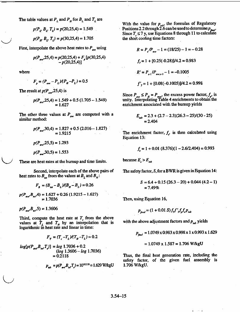
The table values at PI. and P,, for BL, and T. are
P(P'v BL, TL) = p(20,25,4) = 1.549
p(P1 , BL, TL) = p(30,25 ,4) = 1.705
First, interpolate the above heat rates to P. using
p(Pf,25,4) = p(20,25,4) + F [p(30,25,4) - p(20,25,4)]
With the value for p,, the formulas of Regulatory Positions 2.2 through 2.6 can be used to determinepr,. Since T < 7 y, use Equations 8 through 11 to calculate the short cooling time factors:
R = P1P - 1 = (18/25) - 1 02= 0.9 8
f7 I + [0.25(-0.28)]/4.2 = 0.983
where
F = (Pý. - PL Y(PH -PL) = 0-5
The result at p(P ,25,4) is
p(P ,25,4) = 1.549 + 0.5 (1.705 - 1.549) = 1.627
The other three values at P• are computed with a similar method:
p(P ,30,4) = 1.827 + 0.5 (2.016 - 1.827) - 1.9215
p(P ,25,5) = 1.293
f = 1 + [0.08(-0.1005)]/4.2 = 0.998
Since P < P. = P ., the excess power factor, f., is unity. Interpolating Table 4 enrichments to obtain the enrichment associated with the burnup yields
E,1 = 2.3 + (2.7 - 2.3)(26.3 - 25)/(30 - 25) = 2.404
The enrichment factor, f, is then calculated using Equation 13:
p(P.,30,5) = 1.553 f = I + 0.01 (8.376)(1 - 2.6/2.404) = 0.993
These are heat rates at the burnup and time limits.
Second, interpolate each of the above pairs of heat rates to Bo, from the values at BL and B.:
FR = (B,,- Bi )/(BH- BL) = 0.26
p(PaBot,4) = 1.627 + 0.26 (1.9215 - 1.627)
= 1.7036
p(PwB,,,5) = 1.3606
Third, compute the heat rate at T from the above values at TL and TH by an interpolation that is logarithmic in heat rate and linear in time:
FT = (T -TL )(TH-TL) = 0.2
log[p(P,•BdT)] = log 1.7036 + 0.2 (log 1.3606 - log 1.7036)
=0.2118
I pb =p(PeB,,Td)= 10°o2 = l.629W/kgU
because E > E1
The safety factor, S, for a BWR is given in Equation 14:
S = 6.4 + 0.15 (26.3 - 20) + 0.044 (4.2 - 1) = 7.49%
Then, using Equation 16,
Pfjmt = (1 + 0.01 S)f 7f' 7fffpl,
with the above adjustment factors and p, yields
Pa = 1.0749 x 0.983 x 0.998 x I x 0.993 x 1.629
= 1.0749 x 1.587 = 1.706 W/kgU
Thus, the final heat generation rate, including the safety factor, of the given fuel assembly is 1.706 W/kgU.
3.54-15
R'= P .,IPo.- I = -O.lO005

APPENDgIXB
ACCEPTABILITY AND LIMITS OF THE GUIDE
-Inherent difficulties arise in attempting to prepare a heat rate guide that has appropriate safety factors, is not excessively conservative, is easy to use, and applies to all commercial reactor spent fuel assemblies. In the endeavor to increase the value of the guide to licensees, the NRC staff made an effort to ensure that safe but not overly conservative heat rates were computed. The procedures and data recommended in the guide should be appropriate for most power reactor operations with only minor limitations in applicability.
In general, the guide should not be applied outside the parameters of Tables 1 through 8. These restrictions, in addition to certain limits on adjustment factors, are given in the text. The major table limits are summarized in Table B.1.
applied to correct for variations in power history that differ from those used in the generation of the tables. For example, the heat rate at 1 year is increased substantially if the power in the last cycle is twice the average power of the assembly. The limits on the conditions in Regulatory Position 2.2 on ratios of cycle to average specific power are needed; first, to derive cooling time adjustment factors that are valid, and second, to exclude cases that are extremely atypical. Although these limits were determined so that the factors are safe, a reasonable degree of discretion should be used in the considerations of atypical assemblies-particularly with regard to their power histories.
Another variable that requires attention is the 59Co content of the clad and structural materials. Cobalt-59
Table B.1 Parameter Range for Applicability
of the Regulatory Guide
In using the guide, the lower limit on cooling time, T, and the upper limit on burnup, B,.O, should never be extended. An adjustment factor, f , can be applied if the specific power, P/', does not exceed the maximum value of the tables by more than 35%. Thus, if P is greater than 54 kW/gU for PWR fuel or 40.5 kW/kgU for BWR fuel, the guide should not be applied. The minimum table value of specific power or bumup can be used for values below the table range; however, if the real value is considerably less than the table minimum, the heat rate derived can be excessively conservative. Also, the upper cooling time limit is conservative for longer cooling times.
In preparing generic depletion/decay analyses for specific applications, the most difficult condition to model is the power operating history of the assembly. Although a power history variation (other than the most extreme) does not significantly change the decay heat rate after a cooling time of approximately 7 years, it can have significant influence on the results in the first few years. Cooling time adjustment factors, f 7 and f '7, are
is partly transformed to 6Co in the reactor and subsequently contributes to the decay heat rate. The 59Co content used in deriving the tables here should apply only to assemblies containing Zircaloy-clad fuel pins. The 6OCo contribution can become excessive for 59Co contents found in stainless-steel-clad fuel pins. Thus, the use of the guide for stainless-steel-clad assemblies should be limited to cooling times that exceed 20 years. Because 6Co has a 5.27-year halflife, the heat rate contribution from 6°Co is reduced by the factor of 13.9 in 20 years.
In addition to the parameters used here, decay heat rates are a function of other variables to a lesser degree. Variations in moderator density (coolant pressure, temperature) can change decay heat rates, although calculations indicated that the expected differences (approximately 0.2% heat rate change per 1% change in water density, during any of the first 30-year decay times) are not sufficient to require additional corrections. The PWR decay heat rates in the tables were calculated for fuel assemblies containing water
3.54-16
Parameter BWR PWR T (year) 1-110 1-110 B, (MWd/kgU) 20-45 25-50 Pav (kW/kgU) 12-30 18-40
K)
holes. Computed decay heat rates .for assemblies
containing burnable poison rods (BPRs) did not
change significantly (•1% during the first 30-year decay) from fuel assemblies containing water holes.
Several conditions were considered in deriving the safety factors (Equations 14 and 15) that were developed for use in the guide. Partial uncertainties in the heat generation rates were computed for
selected cases by applying the known standard deviations of half-lives, Q-values, and fission yields of all the fission product nuclides that make a significant contribution to decay heat rates. This calculation did not account for uncertainties in
contributions produced by the neutron absorption in
nuclides in the reactor flux, or from variations in other parameters. In addition to the standard deviations in neutron cross sections, much of the uncertainty from neutron absorption arose from approximations in the model used in the depletion analysis. In developing the safety factors, these more indirect uncertainties were determined from comparisons of the calculated
total or individual nuclide decay heat rates with those determined by independent computational methods, as well as comparisons of heat rate measurements obtained for a variety of reactor spent fuel assemblies. Note from the equations that the safety factors increase with both burnup and cooling time. This
increase in the safety factor is a result of the increased importance of the actinides to the decay heat with increased burnup and cooling time together with the
larger uncertainty in actinide predictions caused by
model approximations and limited experimental data.
Whenever the design or operating conditions for a spent fuel assembly exceed the parameter ranges accepted in this guide, another well-qualified method
of analysis that accounts for the exceptions should be used. A well-qualified method would be one that has a
technical basis that is validated against measured heat
rate data and has been demonstrated to provide conservative heat-rate estimates (i.e., per justified safety factors consistent with the measured data) for the extended design or operating conditions.
3.54-17
z w
_nJ
1Au
00
U.
)jo E
10 0
60
0 0 0ID
0 0D ~cao
=20 0
CC
0 0 C
a
804- to C a L0 0 0-L
,a) CL0. o.. < 00
0 < N
0.
m Lo a 'a .a .C ij Q
(0 0
S0~ .- 08
0 G -aC
=_. "U-W I M Coo
I
3'
'0
4
it *Ii
SW I..
I 'S a. a I. a
U
0.
-0-0
MRWISIM
700-ro00000V .I * * *. . . . . . .
;4444446
44
1* WI
SW I-.
I 4
a
a. a
S. p U
RON
3
0. I c �u
3AI
I S In U
a. a
a U
V
U
p.. '4
IS
**I*g C ecp
0 0 a0~I~ ~0k *0 0,64
4-eq~p pe pope
wwww 444.0, "4d4:00' A4 w C~
.. 4 .d.9..0.000T!.
)
0
z w 0.
I&
I
a. U '4
U
00
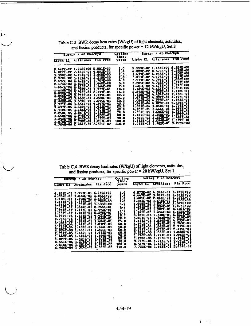
Table C.3 BW .decay heat rates (W/kgU) of light elements, actinides, and fission products, for specific power , 12 kW/kgU, Set 3
Burnup = 40 lHd/kgU Coolinq Burnup 4 45 MHd/kgU
Eight~ E•Actinides Fis Prod years Light El Actinides Fis Prod
5.467E-02 1.008E#00 S.001E400 1.0 5.559E-02 1.186E400 5.2891400
4.027E-02 7.380[-01 4.00Z£*00 1.4 4.089E-OZ 8.S74E-01 4.2651400 3.390E-02 5.141E-01 3.0681*00 2.0 3.439E-02 6.255-01 3.300E*00
2.970E-OZ 4.1981-01 Z.31E500 Z.8 3.013E-0Z S.]75E-01 Z.S1E700 Z.4971-02 3.875E-01 1.709E#00 4.0 Z.533E-OZ 4.791E-01 1.850E+00
2.173E-02 3.8Z7E-03 1.440E*00 5.0 2.20SE-02 4.723E-01 1.593E+00 1.657E-02 3.8101-01 1.364E#00 7.0 1.681E-02 4.6751-01 1.293E+00
1.11ZE-02 3.797E-01 9.777E-01 10.0 1.129E-02 4.A6[E-01 1.067E.00 5.800E-03 3.760E-01 8.199E-01 15.0 S.89Z1-03 4.533E-01 9.1101-01 3.066E-03 3.7112-01 7.139E-01 20.0 3.1181-03 4.434E-01 7.930E-01 1.641E-03 3.653E-01 6.280E-01 Z3.0 1.671E-03 4.33ZE-01 6.973E-01 8.90SE-04 3.5901-01 5.54S. -01 30.0 9.086E-04 4.:29E-O: 6.1551-01 9.771E-04 3.4S6E-01 4.347E-01 40.0 2.841E-04 4.OZ9E-0]: 4.824E-01 9.697E-05 3.320E-01 3.4ZZ-01 SO.0 3.001E-04 3.840E-01 3.797E-01 4.118E-O5 3.1881-01 Z.701E-01 60.0 4.286E-OS 3.666E-01 2.996E-01
.Z501-0S 3.064E-01 2.134E-01 7C.0 Z.3571-0S 3.50SE-01 2.367[-01 I. ESE-GS Z.9481-01 1,688E-01 80.0 1.6291-OS 3.358E-01 1.8721-01 1.4ZZ1-OS 2.8401-01 1.33SE-01 90.0 1.307E-05 3.ZZ31-01 1.481E-01 1.0781-0S Z.739E-01 1.0S7E-01 100.0 1.13SE-0S 3.099E-01 1.17Z2-01 9.704E-06 Z.646E-01 8.36SE-02 110.0 1.0ZZE-OS 2.9851-01 9.979E-02
Table C.4 BWR decay kict rates (W/KggU) of light elements, actinides, and fission products, for specific power '20 kW/kgU, Set 1
Burnup a 20 O ,Wd/kqgU Cooling Burnup a 25 ttd/,kgU Time; ---des
Light E1 Actinides Fis Prod years Light El Actinxdes Fis Prod
6.2811-02 2.957[-01 5.1901400 2.0 6.5731-02 4.366E-01 5.764E400 4.084E-02 t.036E-01 3.E53E*00 1.4 4.447E-01 3.012E-01 4.341E+00 3.278*-02 1.3981-01 2.680E100 2.0 3.60S5-02 t.0681-01 3.073F400 2.332E-02 1.119E-01 1.789E400 t.8 3.123E-02 1.648E-02 2.IOE400 Z.36ZE-02 1.0511-02 1.133E+00 4.0 2.60SE-02 1.5311-01 .1.370E+00 2.047E-02 1.064E-01 6.744E-01 5.0 2.2f6Z-02 1.536E-01 1.071E400 1.SSE-OZ 1.113E-01 6.493E-01 7.0 1.716E-02 1.58Z1-01 8.1013-01 1.03ZE-02 2.181E-01 5.29SE-02 10.0 1.14SE-02 1.646E-Cl 6.620E-01 S.299E-03 1.271E-01 4.431E-01 IS.0 5.905E-03 1.7301-01 S.SZIE-01 2.7481-03 1.337E-01 3.8646-01 20.0 3.081E-03 1.788E-01 4.610E-01 1.436E-03 1.384E-01 3.406E-01 25.0 1.6231-03 1.826E-01 4.2331-01 7.S70E-04 1.4161-01 3.0121-01 30.0 6.6401-04 1.849E-01 3.7431-01 2.182E-04 1.4SOE5-01 2.366E-01 40.0 2.S54E-04 1.865E-01 2.939E-01 6.936E-05 1.4561-01 1.86SE-01 S5.0 8.361E-OS 1.8S31-01 2.31SE-01 2.71ZE-OS 1.447E-01 1.473E-01 60.0 3.3ZZ-OS 1.826E-01 1.8281-01 1.4491-OS 1.42S1-01 1.164E-01 70.0 1.7481-OS 1.791E-01 1.44SE-01 1.027E-05 1.404E-401 9.2081-02 80.0 1.Z20E-OS 1.7531E-01 1.143E-01 8.5S1.-06 1.37E4-01 7.Z861-02 90.0 9.719E-06 1.713E-01 9.0401-02 7.6181-06 1.3SIE-01 S.767[-02 100.0 8.5191-06 1.673E-01 7.15S1E-O 6.966E-06 1.324E-01 4.5631-OZ 110.0 7.72ZE-06 1.6351-01 S.664E-02
3.54-19
I 1 .1
)
�uu�
0 4.10
.2
.0 a�.
:30000" ...... me"
..... .... ... . M "!
0
4, v
00
1�L POu
ii
.2
.0
If 16
64
,40
4. to
.9
b
b K
2 4
a.
C 54 a
INN
rý 0
*Osea0000 *0 0000000000a
ch.ON moow :IM NUMENZNNNNN,.N
u09iI 00. MI'.
*~~~~ .1 CC. . 40** ** -. .
O*0000000000 nit0
Ma'. PA .4N(O~.a.5 m .U 0 toN
NC1001 WP OpO 0. MIT
00000000000000006000
%.n N .40am.Ca1Na0.a3
000000
0*0OO 0o *01oooo 106
off , '04 s.0 .p004.4
)
t
I
C
'4
'I
9, .4 II.
U .4 a .4
.4 11 'a 5, b .4
)
rt
0 0f 3g13.
I r
0.
N
.4
I, 0 U .4 a .4 'a
.4 II
4. a b
0n
el;
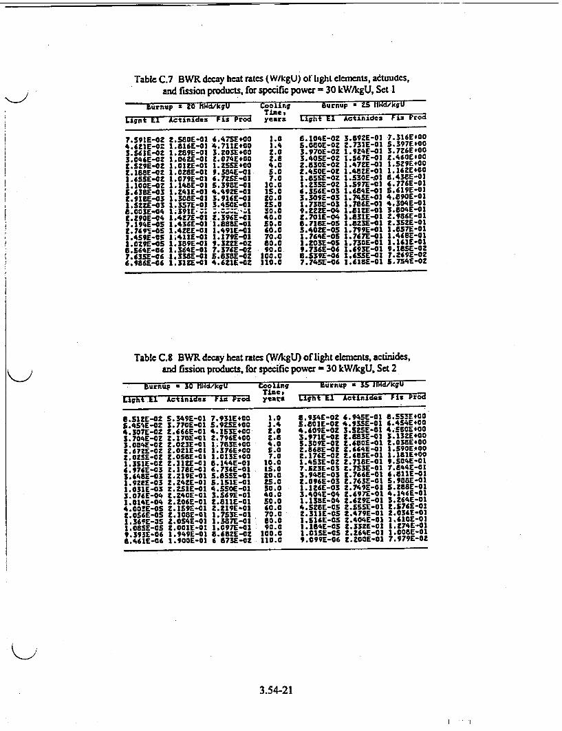
Table C.7 BWR decay heat rates (W/kgU) of light elements, adtmudcs, and fission products, for specific power = 30 kW/kgU, Set 1
Burnup a 20 hWd/kgU Cooling Burnup = 25. II1d/kgU _________________________ Time, * ______________
Lignt El Actinides Fis Prod years Light El Actinide.s FLs Prod
7.591E-02 ZSSE0-01 A.4,75E.00 1.0 5.104E-02 3.89ZE-01 7.316E#00 4.621E-O2 1.816E-01 4.?711EO0 1.4 S.0801-OZ 2.731E-01 S.397E100 3.S4IE-OZ 1.289E-01 3.203E+00 Z.0 3.970E-02 1.924E-01 3.726E*00 3.046E-02 1.0621-01 2.074E+00 2.8 3.405E-0Z 1.567E-01 Z.460E#00 Z.S29E-OZ I.0SZE-01 I.ZSSEO5 4.0 2.830E-02 ].472E-01 1.S291400 2.188E-02 1.0ZSE-01 9.384E-01 5.0 2.450E-02 14aZE-01 1.162E4+00 I.ASSE-02 1.079E-01 6.7Z,1-01 7.0 I.85SE-OZ 1.530E-01 6.438E-01 1.1001-0Z 1.148E-01 5.3981-01 10.0 I.Z35E-02 1.597E-01 6.776E-01 5.638E-03 1.241E-01 4.492-0a 15.0 4.356E-03 1.;841-01 5.619E-01 E.915E-03 1.308E-01 3.916E-03 20.0 3.309E-03 1.74SE-01 4.890E-01 I.SZZ-03 1.357E-01 3.430[-01 ZS.O 1.7381-03 1.786E-01 4.304E-01 8.003E-,04 I.391E-Z; :;z,:; 30.0 9.222-04 1.812E-01 3.804E-01 2.29OE-04 1.427E-01 2.396"1-01 40.0 2.701E-04 1.631E-01 2.986E-01 7.194E-.S 1.436E-01 1.88SE-01 50.0 8.718E-OS 1.8231-01 2.3SZ-01 2.749!-0S 1.4ZE1-01 1.491E-01 60.0 3.40ZE-OS 1.799E-01 1.857E-01 1.4S9E-0S 1.4111-01 1.179E-01 70.,0 1.764E-05 1.767E-01 1.4681-01 1.0Z91-0S 1.389E-01 9.3Z21-02 80.0 I.O3E-OS 1.7301-01 1.161]-01 6.S64E-06 1.3641-01 7.376E-0? 90.0 9.736E-06 1.493E-01 9.185E-02 7.435E-06 1.3381-01 5.838E-OZ 200.0 8.$391-06 1.63SE-01 7.2691-OZ 4.98U6-06 1.3121-01 4.622E-02 110.0 7.745E-06 1.615E-01 S,754E-02
Table C.8 BWR decay heat rates (W/kgU) of light elm•ents, actinides, and fission products, for specific power - 30 kW/kgU, Set 2
burnup 30 Wi'd/lkgU Coo ling Burnup a 35 IlWd/kgU Time, I
LEht .E1 Actinides Frz rod yeats Light Il Actinides Fis Prod
8.SZE-02 5.349E-01 7.931E+00 1.0 8.934E-OZ 4.9451-01 8.5531*00 5.4S'E-02 5.7701-01 5.9251400 1.4 5.801E-02 4.93S1-01 6.4541*00 4.307E-02 2.4661-01 4.1531400 2.0 4.609E-0Z 3.SSE-01 4-5804E00 3.704E-02 Z.1701-01 2.796E100 2.6 3.971E-02 Z.8831-01 3.13ZE400 3.084E-0Z Z.OZ30-01 1.783100 4.0 3.3091-02 2.680E-01 2.038E400 2.67ZE-OZ 2.0Z1E-03 1.376E#00 5.0 Z.868E-02 9.664E-01 1.5901E00 2.OZS0-OZ Z.OSSE-01 1.013E*00 7.0 2.176E-02 2.68SE-01 1.181E100 1.331E-02Z .1121-01 6.144E-01 10.0 1.4531-0Z 2.7181-01 9.504E-01 6.976E-03 2.178--01 4.736E-01 IS.0 7.523E-03 2.7531-01 7.644E-01 3.6481-03 2.219E-01 S.SS-01 20.0 3.948E-03 2.7661-01 ;.811E-01 1.921E-03 Z.Z421-O1 5,1511-01 ZS.0 Z.0961-03 2.7631-01 5.9881-01 1.031E-03 Z.,S11-01 4.SSOE-01 30.0 1.1•26-03 z.7491-01 5.288E-01 3.076E-04 2.2401-01 3.569E-01 40.0 3.404E-04 2.697E-01 4.146E-01 1.014E-04 Z.2061-01 1.811E-01 SO0. 1.1381-04 2.629E-01 3.264E-01 4.00!1E-OS .1591-01 2.219E-01 40.0 4.SZ8-0S Z.SSS-1-01 2.576E-01 Z.056E-OS 2.1081-01 1.7S31-01 70.0 2.311E-05 2.479E-01 2.036E-01 1.3691-3S 2.054E-01 1.387E-01 60.0 1.S161-05 2.404E-01 1.6101-01 1.0851-OS 2.001E-01 1.097E-01 90.0 1.1541-OS 2.332E-01 1.2741-01 9.393E-06 1.949E-01 8.682E-02 100.0 I.0S1-0 Z.Z64E-01 1.0080-01 8.461E-06 1.900E-01 6 873E-02 110.0 9.099E-06 2.ZOE-01 7.979E-02
3.54-21
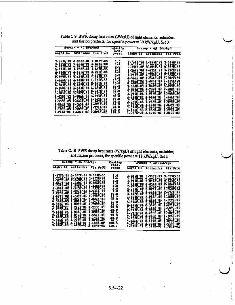
Table C.9 BWR decay heat rates (W/kgL) of light elements, actinides, and fission products, for specific power - 30 kW/kgU, Set 3
Durnup a 40 IlW/kgU Cooling EUinup x 45 tfldkjU Time, # Light 91 Actinides Fl: Frod years Light El Actinides Fiz Prod
9.37]1-02 0.8a0E-01 9.0291+00 1.0 9.716E-02 1.063E+00 9.546E100 6.150E-02 6.345E-01 6.8831E00 1.4 6.41CE-02 7.7051-03 7.334E100 4.91ZE-02 4.590E-01 4.945E+00 2.0 5.132E-O S.651]-01 S.3221*00 4.241E-0! 3.780E-01 3.4351400 Z.8 4.435E-02 4.6941-01 3.742E#00 3.538E-0Z 3.5071-01 Z.Z77t1.00 +4.0 3.701E-02 4.3571-01 Z.3I8E400 3.0681-0Z 3.4701-03 1.7941400 3.0 3.2111-0Z 4.299E-10 2.0001+00 2.3291-0! 3.463E-01 1.3431100 7.0 2.4351-02 4.2641-01 1.507E+00 1.556E-02 3.4601-01 1.0811[00 10.0 1.6Z9E-OZ 4.2Z4E-O 1.214E+00 8.070E-03 3.441E-01 8.8991-01 135.0 8.4S57-03 4.1491-01 9.982z-o0 4.2431-03 3.407E-01 7.719E-01 20.0 4,.1,E-03 4.067E-01 8.6331-01 Z.2581-03 3.3631-01 6.7a3E-0o 25.0 2.3721-03 3.9801-03 7.6001-01 f.h6E-03 3.3131-01 5.9571-01 30.0 1.Z.BI-03 3.8921-01 6.707E-01 3.703E-04 3.2021-01 4.692E-01 40.0 3.9191-04 3.7189-01 s.Z,5-01 1.2481-04 3.0861-01 3.6931-01 S0.0 1.3ZS-04 3.ss31-01 4.1361-01 5.001E-05 2.9731-01 2.9141-01 60.0 5.3431-05 3.4001-01 3.2631-01 .5s51-0s z.8a66-o0 t.3031-01 70.0 2.7301-os 3.26oz-01 2.5781-01 1.i69-0s z.7651-o0 i.821-o1 80.0 1.7771-05 3.131E-01 2.0391-01 1.297e-05-2.671E-01 1.4411-01 90.0 1.3761-05 3.0141-01 1.613E-01 1.1E01-0s .5831-e0 1.1401-01 100.0 1.1731-05 2.9061-01 1.276E-01 9.9131-06 Z.501-01 .9.0241-02 110.0 2.04779-05 z.a86z-0, 1.oso0-o
Table C. 10 PWR decay heat rates (W/AgU) of light eleancts, actinides, and fission products, for specific power =18 kW/kgU, Set 1
Burnup a .5 i1Wd/kgU Cooling Burnup a 30' tmlHd/kgU Times,
Light E1 Actinidis Fi: Prod years Light El Actinides FL: Prod
1.19EE-01 4.3771-01 5.359E100 1.0 1.269E-01 3.911E-01 5.855E+00 .06ZE-01 3.0021-01 4.0791+00 1.4 2.130E-01 4.091E-01 4.4871E00 9.S79E-02 2.04SE-01 2.9081.00 2.0 1.021E-01 Z.814E-01 3.249E100 8.aS!E-02 I.620E-01 t.0061+00 2.8 9.113E-02 2.241E-01 Z.Z86E100 7.2621-02 1.501E-01 1.3ZE8100 4.0 7.7421-02 2.0721-01 1.5501E00 6.3311-02 I.S15E-01 1.053E#00 5.5 6.771E-02 2.071E-01 1.2451#00 4.369E-02 1.5671-01 8.0311-01 7.0 3.1911-02 2.116E-01 9.5979-01 3.275E-02 1.641E-01 6.609E-01 10.0 3.49ZE-02 2.18ZE-0 7.9051-01 1.696S-01 1.7391E-01 5.30E-01 13.0 16808E-0! 2.2641-01 6.6001-01 8.806s-03 1.3071-01 C.8221-I1 zo.0 9.359E-03 2.315E-01 5.7.91[-01 4.5891-03 1.855E-01 4.Z47E-01 25.4 4.894E-03 2.351E-01 5.060E-01 z.4061-03 1.885E-01 3.7551-01 30.0 2.566E-03 2.3671-01 4.471E-01 6.8721-04 1.9101-01 2.9451-01 40.0 7.341E-04 2.366E-01 3.509E-01 Z.2351-04 1.9051-01 2.3Z39-01 50.0 2.399E-04 Z.3361-01 2.7641-01 9.681-05 1.8821[-01 .8341-01 60.0 1.0471-04 2.290E-01 2.182E-01 6.0719-05 1.849E-01 1.4501-01 70.0 6.6201-05 2.238E-01 1.724E-01 4.9121-05 1.812E-01 1.1471-01 80.0 3.3791[-OS 2.1831-01 1.3641E-01 4.4ZSE-05 1.77Z1-01 9.07ZE-02 90.0 4.8561-05 2.1271-01 1.079E-01 4.133E-05 1.7331-01 7.180E-02 100.0 4.5411-0S 2.0721-01 8.5391-02 3.904E-05 1.693E-01 3.684E-02 110.0 4.Z93E-0S Z.019E-01 6.759E-02
3.54-22
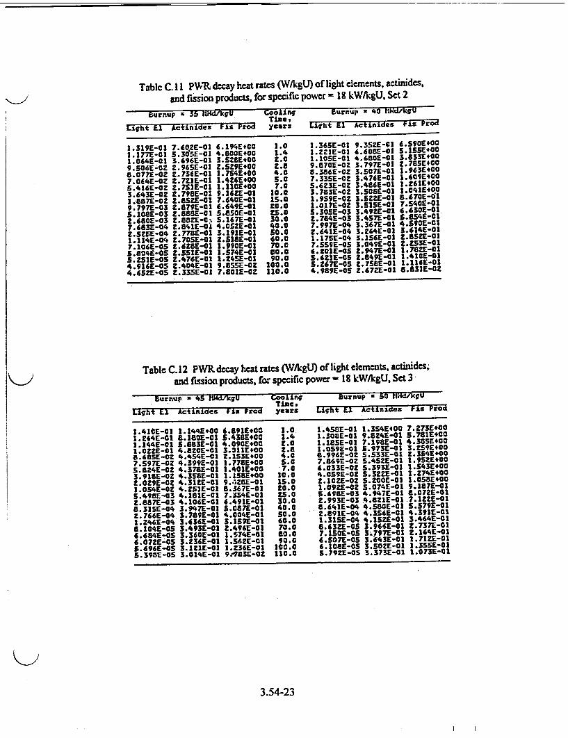
Table C. 11 PWR, decay heat rates (W/kgU) of light elements, actinides,
and fission products, for specific power = 18 kW/klgU, Set 2
Burnup r 55 ItHd/kgU Cooling Burnup = '40 Wd/kgU
Light El ActInides Fis Prod years Liqht E1 Actinides FLi Prod
1.319E-01 7.60,ZE-01 6.194E+00 1.0 1.365E-01 9.35ZE-01 S.$901E0G
1.177E-01 5.305E-01 4.800E400 1.4 1.22S1-01 6.608E-01 5.155E+00
1.064E-01 3.696E-01 3.5261400 2.0 1.10SE-01 4.680E-01 3.8333100
9.506E-0 z2.96SE-01 2.529E+00 2.8 9.870E-0Z 3.7971-01 2.785E400
8.077[-0Z Z.734E-01 1.754•• 00 4.0 8.380E-0Z 3.507E-01 1.963E100
7.064E-0Z Z.721E-01 1.4Z6E+00 5.0 7.33SE-02 3.476E-01 1.609E400
5.416E-OZ 1.7S:E-01 1.110E100 7.0 S.6Z3E-0Z 3.486E-01 1.2611+00
3.643E-02 2.798E-01 9.16Z1-01 10.0 3.783E-02 3.506E-01 l.q04*E00
1.587E-02 Zt.85 -01 7.640E-01 15.0 1.959E-02 3.5Z-01 8.0670--1 9.797E-03 2.879E-01 6.649E-01 ZO.0 1.01?E-02 3.5151-01 7.540E-01
5.108E-03 2.088E-01 S.aSOE-01 2S.0 5.305E-03 3.49ZE-01 6.630E-01
2.6601-03 Z. 8ZE-0% S.1671-01 30.0 2.784E-03 3.4571-01 56 ,•5-01
7.683E-04 Z.8411-0 4.0SZE-01 40.0 7.997E-04 3.367E-01 4.$9-01
2.521E-04 2.775T-01 3.191E-01 50.0 2.641E-04 3.264E-01 3.614E-01
1.II4E-04 2.705E-01 2.518E-01 60.0 1.1751-04 3.156E-01 Z.SSZE-01 7.1061-05 1[.628-01 1.9901-01 70.0 7.55SE-05 3.049E-01 2.253E-01 5.804E-05 t.$511-01 1.574E-01 60.0 6.201E-05 t.947E-01 1.782E-01 5.251E-05 2.4761-01 1.24SE-01 90.0 S.4211-05 2.609E-03 1.410E-01
4.916E-05 Z.A04E-01 9.8SE-OZ 100.0 5.2671-0S 2.7S81-01 1.116E-01 4.d5ZE-05 Z.3351-01 7.8011-0Z 110.0 4.9891-05 2.672E-01 8.831E-02
Table C.12 PWR decay heat rates (W/kgU) of light elements, actinides;
and fission products, for specific power- 18 kW/kgU, Set 3
Burnup a 45 MlLd/k"U CAo.Lin" Burnup s 50 ttHd/kVU _"_ Time#, _e
Light 11 Actinides Fls Prod years igUht E1 Acti•ndas Fis Prod
1.4101-01 1.144E+00 6.891E#00 1.0 1.4581-01 1.354E400 7.273E+40
1.264E-01 8.1801-01 5.438E100 1.4 1.308E-01 9.8Z41-01 5.781E00 1.144E-01 S.8831-01 4.0904E00 2.0 1.185E-01 7.198E-01 4.38S5*00 I.0ZZE-01 4.820E-01 3.)114E00 2.8 I.059E-01 5.973E-01 3.1591+00 8.6851-02 4.4541-01 2.153E1.0 4.0 6.996E-02 5.533E-.01 2.354E*00 7.597E-02 4.399E-01 1.7781+00 S.0 7.869E-02 5.4521-01 1.951E+00 S.824E-02 4.378E-01 1.4011.00 7.0 6.033E-02 S.393E-01 1.S43E*00
3.91GE-02 4.351E-01 1.158E+00 10.0 4.059E-O2 S.32ZE-01 1.2741*00
2.029E-02 4.31EE-01 9.428E-01 15.0 Z.102E-02 5.20OE-01 1.0581*00 1.054E-02 4.252E-01 8.367E-01 20.0 1.092E1-0 S.074E-01 9.187E-01 5.498E-03 4.181E-01 7.354E-01 Z5.0 5.6981-03 4.947E-01 8.072E-01 Z.887E-03 4.106E-01 6.491E-01 30.0 2.993E-03 4.8a1E-01.7.1Z21-01 8.3151-04 3.947E-01 5.0871-01 4,0.0 68.46E-04 4.58E-01 5.5791-01 2.766E-04 3.789E-01 4.004E-01 50.0 2.691E-04 4.3541-01 4.391E-01 .246E-04 3.636E-01 3.157E-01 60.0 1.3151-04 4.15.E-01 3.464E-01
5.104E-05 3.493E-01 2.496E-01 70.0 6.63ZE-05 3.944E-01 2.7371-01 6.684E-05 3.3601-01 1.574E-01 80.0 7.150E-05 3;.7971E-01 2.164E-01
6.0721-05 3.236E-01 1.562E-01 90.0 6.507E-0S 3.A3E-01 1.712E-01 5.4961-05 3.121E-01 1.236E-01 100.0 6.1081-OS 3.S0ZE-01 1.350E-01 5.3986-05 3.014E-01 9.-783-0Z 110.0 5.792E-OS 3.373E-01 1.073E-01
3.54-23
is
J0
Ad
.4
.4
9
La
0*a*~4~ -9I 9999999 I
wwwua w'w w
Mri 100 aa" oo.
# 9 1 l o oWli s i t .4Wtfff~wafw~d.W.NW.
0ooo000o0 o00000
a W' Noq1.~~ W'w 41 '1 l
IMMOM00000000
t 4
a.
C I.
$0
.4 t%
I'
b 'SN .468.
I.
�1.
if
in
:too
to -?) N
.4
N 6 U .4 C .4
ý-4 baa
ba* It CISM. ism "'itma seam ~ ~h44WW W~a5IW 'mib4ma
Maim go maiO. 9w Ella
Sdh*9 5 u - - WNW. WN
*........... *'C1MiIMM4M.5j4, 4 14q, 4
O10~00@00o0000000o .'
s l
ww. 0000000.4
3
k
I of
16.
)
t%
31..).
b
I.
a.
C I' 0
'a.
N V U .4
.4 M a' C 'Ii .4 .8
)
kn
CAI
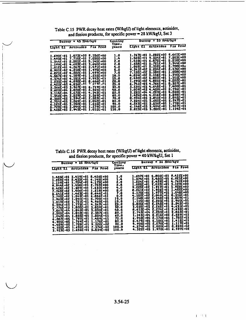
Table C. 15 PWR decay heat rates (W/kgU) of light elemenrts, actinides, and fission products, for specific power - 28 kW/kgU, Set 3
Burnup a 45 hVJd/kgU Cooling Burnup = 50 hld/kgU _______ _______ ______ Time, _ _ _ _ _ _ _ _ _ _ _
Light El A•tinides Fis- PFro years Light El Acti-nides Fis Pzod
1.690E-01 1.073E400 9.136E400 .0 1.767E-01 .1.282E400 9.661E400 1.493E-01 7.710E-01 7.058E#00 1.4 1.S651-01 9.334E-01 7.503E.00 1.344E-01 5.S8SE-01 S.1451.00 2.0 1.410E-01 4.8701-01 5.518[400 1.199E-01 4.403E-01 3.640E#00 t.8 IA.281-01 5.7Z1E-01 3.944E400 1.01[]-01 4.267E-01 Z.4711[.00 4.0 1.068E-01 5.310E-01 2.708940u 8.90]E-02 4.211E-01 1.975E.00 5.0 9.341E-02 5.234]-01 2.1761E00 6.821E-02 4.202E-01 1.4991.00 7.0 7.1$8E-OZ 5.180£-01 1.658400 4.S87E-02 4.1899-01 1.221E.00 10.0 4..814-0Z 5.116E-01 1.340E+00 t.374E-OZ 4.151E-01 9.993E-01 1S.0 Z.492g-02 S.003E-0 1.10ZE400 1.233E-02 4.098E-01 8.666E-01 tO.0 I.Z.941-O 4.886E-01 9.521E-01 6.4AZ£-03 4.036E-nl 7 II-ln. 25.o 6.741E-03 4.766E-01 6.3871-01 3.366E-03 3.967E-01 6.719E-01 30.0 3.534E-03 4.6481-01 7.400E-01 9.603E-04 3.820]-01 S.2441-01 40.0 1.009E-03 4.4201-01 $.796E-01 3.114E-04 5.6721-01 4.143E-01 50.0 3.Z8SE-04 4.[091-o1 4.5601-01 1.341E-04 3.529E-01 3.269E-01 60.0 1.424E1-0 4.01(E-01 3.598E-01 8.388E-05 3.394E-01 t.S83E-01 70.0 8.954E-05 3.841E-01 2.8421-01 6.7641-OS 3.269E-01 2.0421-01 10.0 7.2641-05 3.681E-01 Z.Z47E-01 6.l12[-OS 3.15ZE-01 1.616E-01 90.0 6.563E105 3.5361-01 1.778E-01 5.T7ZE-05 3.044E-01 1.279E-01 100.0 6.146E-05 3.404E-01 1.407E-01 5.4M51-05 2.943E-01 I.0IZ-01 110.0 5.8231-OS 3.28ZE-01 1.114E-01
Table C. 16 PWR decay heat rates (W/kgU) of light elements, actinides, and fission products, for specific power - 40 kW/kgU, Set 1
Burnup a 25 'h1d/kgU ooling Burnup x 50 lHd/.kgU _______ ______ ______ Tima, _ _ _ _ __ _ _ _ _ _
Light El Actinides FLl Perod years LIht El Actimides Fi: Prod
1.4851-01 3.419E-01 8.456E.00 1.0 1.607E-01 4.8001-01 9.4114E00 I.259 -01 Z.43SE-01 6.1451.00 1.4 1.374E-01 3.4201-01 6.92E1400 1.119g-01 1.754E-01 4.175E.00 1.0 .1.24-01 2.4591-4l 4.7611400 9.944E-02 1.4581-01 2.702E*10 Z.8 1.088]-01 t.0331-01 3.1291E00 8.428•-02 1.389E-01 1.630E4.00 4.0 9.225E-OZ 1.917E-01 1.9281.00 7.3651-02 1.406E-01 I.ZISE00 5.0 8.0611-02 3.9Z6E-01 1.4551*00 S. 41 -02 1.463E-01 8.646E-01 7.0 6.1751-02 1.977E-01 1.0451E00 3.7931-0Z 1.543E-01 6.8G6E-01 0.0 4.1521-02 2.0491-01 8.31SE-01 1.9631-02 1.6461-01 5.700E-01 31.0 2.1481-02 .2.140-01 6.859E-01 1.0191-02 1.721E-01 4.9601-01 0.0, 1.115E-02 2.2031-01 5.9601-01 5.304E-03 1.773E-01 4.367E-01 5.0o 5.805E-03 2.24Z-01 5.243E-01 2.776•-03 1.6081-01 3.859E-01 30.0 3.0381-03 2.2651-01 4.631E-01 7.6671-04 1.841E-01 3.030E-01 40.0 8.612E-04 2.2741-01 3.633E-01 2.50S5-04 1.84ZE-01 t.3871-01 50.0 2.7431-04 2.ZS3E-01 2.86Z-001 1.04Z1-04 1.8251-01 1. 88E-01 60.0 1.143E-04 2.M4161-01 .2•591-l 6.28e71-05 1.797E-01 1.489E-01 70.0 6.90Z1-05 2.2701-01 1.78SE-01 4.98SE-0S 1.764E-01 1.178E-01 80.0 S.4791-05 2.120E-01 1.41ZE-01 4.4591-05 1.7261-01 9.3201-02 90.0 4.905E-05 2.0701-01 1.117E-01 4.1SSE-OS 1.69Z1-01 7.376E-O 100.0 4.574E-05 Z.OZO-01 8.839E-02 3.9231-O5 1.456E-01 5.839E-02 110.0 4.32ZE-OS 1.97Z1-01 6.997E-02
3.54-25

Table C. 17 PWR decay heat rates (W/kgU) of light elements, actinides, and fission products, for specific power - 40 kW/kgU, Set 2
Btrnup = 35 t ld.kgU Cooling- Sunup a 40 WUCRlcgU Times
Light El Actinides Fixs Prod year: Light El Actinides Flu Prod
1.706E-01 6.341E-01 1.010E101 1.0 1.800E-01 7.998E-01 1.084E101 1.469E-03 4.S381-01 7.SOE.00 1.4 I.SS7E-1I 5.766E-01 8.1319#00 1.311E-01 3.277E-01 S.233E,00 2.0 1.393E-01 4.ZOIE-01 5.721E00 1:.1671-03 2.709E-01 3.4961*00 2.8 1.239E-01 3.4871-01 3.8731+00 9.891E-02 Z.S381-01 Z.Z011.00 4.0 1.0SIE-a 3.258E-01 2.4791400 8.644E-0Z 2.534E-01 1.6814E00 5.0 9.183E-02 3.2381-01 1.911E+00 6.6211-02 2.571E-01 1.zZ01.00 7.0 7.034E-0Z 3.Z571--03 1.397E100 4.45ZE-02 2.626E-01 9.7131-01 10.0 4.729E-02 3.Z87E-01-I.IIZE#00 2.304E-02 2.689E-01 7.990E-01 13.0 2.447E-02 3.3141-01 9.1251-01 1.195E-02 2.726E-03 6.9349-01 20.0 I.Z70E-02 3.318E-01 7.911E-01 6.2Z4E-03 2.743E-01 6.096E-03 25.0 6.612Z-03 3.306E-01 6.9511-01 3.Z$8E-03 2.74TE-0l 5.3821-01 30.0 3,4611-03 3.2811-01 6.136E-01 9.218E-04 Z.7171-01 4.220E-01 40.0 9.818E-04 3.Z071-01 4.8091-03 2.9461-04 2.665E-01 3.323E-01 50.0 3.134E-04 3.217E-01 3.786E-01 1.2301-04 2.601E-01 2.62•1-01 60.0 1.311E-04 3.022E-01 2.987E-01 7.449E-05 2.533E-03 2.07ZE-01 70.0 7.9601-OS 2.9271-01 2.360E-01 5.924E-05 2.464E-02 1.6391-03 80.0 6.3401-0S 2.8341-03 1.866E-01 S.310E-05 2.3941-01 1.2961-01 90.0 .68SE--05 2.746E-01 1.477E-01 4.956E-0S 2.331E-01 3.026E-01 100.0 S.313E-05 2.663E-01 1.169E-01 4.6361-os z.Z68E-01 8.1Zs1-02 110.0 3.0271-os Z.s58-01 9.249E-02
Table C. 18 PWR decay heat rates (W/kgU) of light elements, actinides, and fission products, for specific power - 40 kW/kgU, Set 3
BuRnup 2 45 fl•L/IgU CooJ0Lngr burnup * 50 fl4/kgLU Time,
Light E1 ActiniLdes el Prod years Light EL Actinzdes Fl* Prod
1.901E-01 9.994E-01 1.1399+01 1.0 2.001E-01 1.2061V,00 1.0614OI 1.65ZE-01 7.266E-01 8.6ZZ1.00 1.4 1.746E-01 6.8671-01 9.1931*00 1.480•-01 5.34S1-01 6.1381,00 2.0 1.651E-01 6.6121-01 6.6001400 1.3181-01 4.4601-01 4.209E#00 z.8 1.394E-02 5.560E-01 4.57ZE100 1.118E-01 4.157E-01 2.738st00 4.0 1.1821-01 5.184E-01 3.010E100 9.767E-02 4.1141-01 2.130E#00 3.0 1.033E-01 5.114E-01 Z.35SE100 7.482E-02 4.1021-01 2.367E100 7.0 7.9171-02 5.064E-01 1.7391400 3.030E-02 4.0921-01 1.Z46,Ot" 20.0 5.323:-02 5.003E-01 1.38ZE100 2.6031-02 4.0591-02 1.02.OVO 135.0 Z.7341-02 4.8961-01 3.1281400 1.3SIE-02 4.01CI-01 8.8351-01 20.0 1.4291-02 4.7831-01 9.7611-01 7.034E-03 3.9511-01 7.75;E-01 23.0 7.443E-03 4.6681-03 8.5681-01 3.682E-03 3.886E-01 6.8W6r-02 30.0 3.897E-03 4.5549-01 7.5S7E-01 1.045E-03 3.7461-01 5.3631-01 40.0 1.107E-03 44334E-01 5.918E-01 3.34SE-04 3.604E-01 4.ZZE-01 50.0 3.549E-04 4.130E-01 4.657E-01 1.406E-04 3.466E-01-3.3301-01 60.0 1.4971-04 3.9431-01 3.673E-03 8.S74E-05 3.336E-03 2.6311-01 70.0 9.166E-0S 3.773E-01 2.90ZE-01 6.84SE-OS 3.ZIS1-02 2.0801-01 80.0 7.336E-OS 3.6201-01 2.29SE-01 6.151E-OS 3.1031-01 1.6461-01 90.0 6.5961-oS 3.4801-03 1.81M1-01 S.749E-OS 2.9981-01 1.302E-01 100.0 6.161G-0S 3.351E-01 1.437E-01 S.44ZE-OS 2.90Z1-03 1.0311-01 110.0 3.841Z-03 3.234E-01 1.1371-01
3.54-26
Value /Impact Statement
A Value/Impact Statement was published with Regulatory Guide 3.54 when it was issued in September 1994. No changes are necessary, so a separate value/impact statement for this proposed Revision 1 has not been prepared. A copy of the value/impact statement is available for inspection or copying for a fee in the Commission's Public Document Room at 2120 L Street NW., Washington, DC, under Regulatory Guide 3.54. The PDR's mailing address is the Mail Stop LL-6, Washington, DC 20555; telephone (202) 634-3273; fax (202) 634-3343.
K-I
3.54-27

)UNITED STATES
NUCLEAR REGULATORY COMMISSION WASHINGTON, DC 20555-0001
FIRST CLASS MAIL POSTAGE AND FEES PAID
USNRC PERMIT NO. G-67
OFFICIAL BUSINESS PENALTY FOR PRIVATE USE, $300


![THE INSURANCE REGULATORY AND DEVELOPMENT AUTHORITY … · 2019-10-01 · 3 THE INSURANCE REGULATORY AND DEVELOPMENT AUTHORITY ACT, 1999 ACT NO. 41 OF 1999 [29th December, 1999.] An](https://static.fdocuments.us/doc/165x107/5e8d08678243c816c643fe6e/the-insurance-regulatory-and-development-authority-2019-10-01-3-the-insurance.jpg)


