Revision Date: November 1, 2017jproc.ca/haida_manuals/radar asdic sonar iff_2018_01_06.pdf ·...
83
Revision Date: November 1, 2017
Transcript of Revision Date: November 1, 2017jproc.ca/haida_manuals/radar asdic sonar iff_2018_01_06.pdf ·...

Revision Date: November 1, 2017

2
Table of Contents 1.0 RADAR SECTION – SEARCH SETS................................................................................... 3 1.1 INTRODUCTION .................................................................................................................... 3 1.2 OPERATION ............................................................................................................................ 4 1.3 Type 271 - Air/Surface Warning Set ....................................................................................... 6 1.4 Type 291 - Air Search Set ..................................................................................................... 10
1.5 Type 293M - Warning Combined Type................................................................................. 13 1.6 Sperry MK II Navigation Radar ............................................................................................ 21 1.7 AN/SPA-4 PPI Indicator ....................................................................................................... 23 1.8 VK5 PPI Indicator.................................................................................................................. 24
1.9 AN/SPS-6C Air Search ........................................................................................................... 25 2.0 RADAR SECTION - GUNNERY ....................................................................................... 28
2.1 Type 285 ................................................................................................................................ 28 2.2 AN/SPG-34 ............................................................................................................................ 35
3.0 IFF SYSTEMS ...................................................................................................................... 37 3.1 Type 242M IFF Interrogator (Mk III) ................................................................................... 40 3.2 Type 253P Transponder ......................................................................................................... 44
3.3 AN/UPX-1A IFF SYSTEM (Mk X) .................................................................................... 45 3.4 AN/UPM-99 ........................................................................................................................... 50
4.0 ASDIC/SONAR SECTION ................................................................................................... 52 4.1 SONAR INSTRUMENT SPACE .......................................................................................... 55 4.2 Type 144Q Search Sonar ....................................................................................................... 55
4.3 Type 147B Depth Finding Set ............................................................................................... 61
4.4 Type 162 ................................................................................................................................ 62
4.5 Type 164B Range and Bearing Finding Set ........................................................................... 62 4.6 AN/SQS-10 Search Sonar ...................................................................................................... 64
4.7 AN/SQS-501 Sea Bottom Identification Set.......................................................................... 70 4.8 Hull Outfit 7A ........................................................................................................................ 72 4.8 SONAR CONTROL ROOM ................................................................................................. 73
5.0 OTHER SOUND BASED SYSTEMS ................................................................................. 78 5.1 Type 761 Depth Recorder ...................................................................................................... 78 5.2 AN/UQC-1B Underwater Telephone ..................................................................................... 79 6.0 OTHER EQUIPMENT .......................................................................................................... 80 6.1 4356M BOTTLE TRANSMITTER ....................................................................................... 80
6.2 RTU........................................................................................................................................ 81
7.0 BIBLIOGRAPHY .................................................................................................................. 81 8.0 ABOUT THE AUTHOR ........................................................................................................ 82 9.0 REVISIONS ............................................................................................................................ 82
3
1.0 RADAR SECTION – SEARCH SETS
This document intends to explain the Radar, IFF and Sonar systems that were used aboard
HMCS HAIDA from the time of her commissioning in August 1943 until she paid off in October
1963. The term ASDIC will be used instead of SONAR sonar where it is historically appropriate.
The various pieces of equipment in each section are not listed in any particular order.
1.1 INTRODUCTION
Radar was the name given during World War II to an electronic system in which radio waves
were bounced off a target in order to detect its presence and locate its position. RADAR is an
acronym derived from the fuller term RAdio Detection And Ranging. A large number of
researchers helped to develop the hardware and techniques of radar, but the development of the
earliest practical radar system is usually credited to the British scientist, Sir Robert Watson-Watt.
The German, Italian and Japanese navies all deployed radar systems of their own but they were
substantially less advanced and much less effective than those used by the Allies. The concept of
detecting an aircraft was considered so important, that each country kept the implementations
very secret.
RDF (Radio Direction Finding) was the acronym used by the Brits as an attempt to disguise
radar technology from the Axis powers. The acronym RADAR was created by Lieutenant
Commander Samuel M. Tucker USN and F. R. Furth in November 1940, for a two-way, pulsed
transmission system, although it was not accepted by all the Allies until 1943. Thereafter it
received general international acceptance.
One of the most important advances made during radar development was the invention of the
cavity magnetron in 1940 by Sir John Randall and Henry Boot. This device generated high-
power pulses in the microwave region of the radio spectrum and was small enough to be held in
the palm of the hand. Originally, the cavity magnetron was made from copper and it simply
melted after short use. By testing various metals, Randall and Boot eventually settled on
molybdenum as the best choice of material for the cavity magnetron. This was a silver-white,
brittle metal with a high heating point. The magnetron could generate pulsed powers of 500 kW
in the S band (10 cm) and 150 kW in the X band (3 cm)
Another advance in radar was duplexing, a method still in use today. This is a switching
technique that allows the same antenna to be used for both transmission and reception by
blocking the receiver during transmission periods. In addition, the echo signals are displayed on
a CRT that uses a radial time-base that rotates in synchronism with the aerial. Since the targets
appear in their correct plan positions relative to the radar station, this form of display is named
the Plan Position Indicator (PPI).

4
The is the same type of 10 cm magnetron brought to
North America by the Tizard Mission in 1940. This specific
example is Canadian Type 8 BX s/n 19152. It was
manufactured by Northern Electric for Research Enterprises
Ltd, a Canadian Crown Corporation. One of the filament
leads is missing. (Photo by Jacques Hamel, VE2DJQ, Le
Musée Québecois de la Radio)
1.2 OPERATION
In radar, a transmitter produces radio waves, which are then radiated from an antenna which
"illuminates" the airspace with those waves. A target, such as an aircraft or ship, that enters this
space, scatters a small portion of this radio energy back to the antenna. This weak signal is
amplified and displayed on a cathode ray tube (CRT) where it can be studied by a trained
operator. Once the presence of the target has been detected, its range and bearing must be
measured. Because radio waves travel at 186,000 mi/sec or 328 yards per microsecond, distance
can be determined by measuring the time taken for a radio wave to travel from transmitter to the
target and back to the receiver. In pulse radar, the radiation is not continuous but is emitted as a
succession of short bursts, each lasting a few microseconds. A wide pulse is desirable because it
delivers more energy and results in stronger signal return for the receiver. Wide pulses also have
a disadvantage -- they limit the minimum distance at which targets can be detected. While the
pulse is being transmitted, the receiver input must be blocked to prevent electrical damage from
the transmitted pulse and to avoid false target indications. If a target is located close to the set, its
echo might return while the receiver is still blocked. In this scenario, no target indication would
be shown.

5
This transmitted pulse of radio energy is emitted upon receipt of a firing signal from a trigger
unit that simultaneously initiates the time-base sweep on the CRT. Once the electronic clock is
started, and when the echo signal arrives on the tube, the time delay can be measured thus
calculating the range. Pulses are emitted at the rate of a few hundred per second and the operator
sees a steady signal on the CRT.
There is one disadvantage of using a high pulse repetition rate. Once a pulse is sent out,
sufficient time must be allowed for the echo to be received. If another pulse is sent out before the
first one is received, false indications will be displayed. The pulse repetition rate, therefore,
determines the maximum workable range of the radar set.
CHAFF
Researcher Robert Langille provides this short passage regarding CHAFF and HAIDA’s
relevance to it. “The development of chaff as a radar countermeasure started in the Second
World War by both the British and the Germans –each unaware that they discovered the same
secret. In July 1942, Lady Joan Curran investigated the idea of generating a cloud of false radar
echoes by dumping packets of aluminum stripes from an aircraft. The invention originated from
the idea by Doctor Reginald Victor (R.V.) Jones in 1937, that a piece of metal foil (Dipole) cut
to half the wavelength of the transmitter radar frequency could be used dispersed from aircraft
and create false target echos to deceive enemy radar operators. The invented device was
codenamed Window by the British, Chaff by the Americans, and Duppel in Germany (named for
the Berlin district where the first tests took place in 1942). However, Duppel saw limited use by
the Germans during World War II as Field Marshall Goering thought it would invite retaliation.
Thus, he ordered subsequent technical records destroyed. The decision not to use the Window
application was a much debated and well-kept secret by the highest levels in Allied Command. It
wasn’t until early 1943 that Prime Minister Winston Churchill approved and authorized its use.
A couple of weeks later, Window was first used by the Royal Air Force (RAF) during Operation
GOMORRAH – the devastating air-raids On Hamburg. During this operation, 90million
aluminized paper strips were dispersed, each measuring 12 by 0.6 inches. Window greatly
contributed to the confusion of the Wurzburg radar system and its operators, blinding them
almost completely and rendering the German air defence batteries useless.
Out of the 791 RAF bombers deployed, only 12 did not return, whereas in previous missions,
without the use of Window, more than 10% of the aircrafts had been lost. For a long time,
Window was only used to attack the German Wurzburg radar systems. Quite notably, and along
with other deceptive devices, it was later used to provide the two false-target (fictitious) fleets
during the D-Day invasion components of Operations Glimmer and Taxable. The success of
these operations was greatly contributed to by the Canadian destroyer HMCS Haida, which was
designated as the lead ship for trials off the coast of Scotland a couple of months prior to the
planned invasion. Haida, along with the Sterling and Lancaster bombers and smaller seaborne
vessels, conducted extensive and successful testing trials which led to the enabling and success
of these two operations". (The Haida reference is from the book " Bodyguard of Lies by Anthony
Cave Brown. The actual mention is at the end of Chapter 8”
6
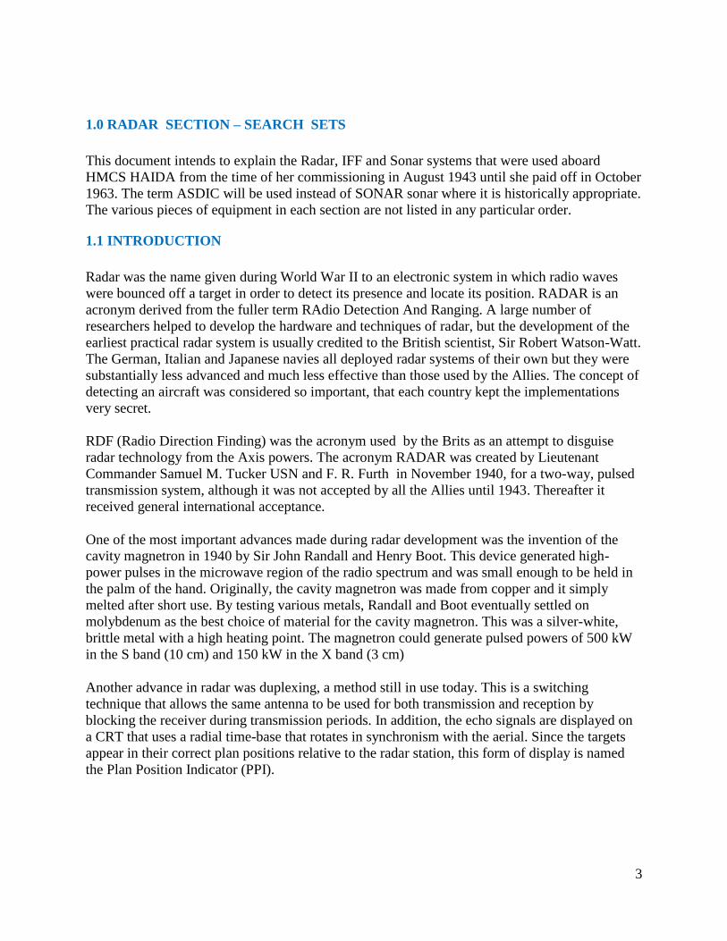
1.3 Type 271 - Air/Surface Warning Set
Antenna location: After boathouse
Equipment location: Some electronics on the back side of the antenna. Suspect the operator sat
directly under the 271 since the antenna was rotated manually.
Installed: During the January 1944 refit in Plymouth
Removed: During November 1944 refit in Halifax.?
While the SW1C prototype was being tested in HMCS Chambly, a new air/surface warning set,
namely the 271, was being tested aboard a Flower class corvette, HMS Orchis in England on 25
March 1941. The 271 set, using the cavity magnetron, operated on ten centimetre wavelengths
(3030 MHz) at a power level of 5 kilowatts, was keyed by 1.5 microsecond wide pulses at a PRF
of 500 Hz. This was quite a breakthrough in technology for the time, however it only used a
ranging display (A scope), a rather inefficient means for a search radar. Its finer and narrower
beam (5 degrees H by 20 degrees V) would permit escorts to detect trimmed-down U-boats at
long distances, consistently and accurately. Sea trials indicated that the 271 could detect a
trimmed-down submarine at 3,500 yards and a periscope at 900 yards. A battle ship was
detectable at 13 nm.
271 set. (Photo courtesy HMS Collingwood Radar Museum)
After the British provided a "gift" magnetron to the USA in November 1940, progress there was
also very rapid. The Type SG set designed by Raytheon went to as a prototype in a destroyer
with a display using a Plan Position Indicator (PPI) in June 1941. The SG worked on a frequency
of 3175 MHz with a 50 kW output.
By the spring of 1943, the large majority of mid-ocean escorts were fitted with the 271, however,
many ships of the Western Local Escort Force were not. To complicate matters, the British
introduced two improved models, namely, the 271P and 271Q. Both of these versions had output

7
power increased from 8 kilowatts in the 271 to 90 kilowatts in the 271Q. This quantum jump in
power output can be directly attributed to a major improvement in magnetron technology. While
the RCN was struggling to fit new ships with first generation 271's, they were also under great
pressure to upgrade existing radars. By September 1943, only fourteen 271Q sets and fifty three
271P's were fitted into RCN vessels along with three original production models. The
introduction of 10 cm radar into fleet destroyers was delayed until the needs of the escorts were
satisfied.
Since the 271 set operated at the 10 cm wavelength, the antenna could be made small enough to
be housed in its own Perspex bubble and mounted on top of the operator's cabin. The antenna
consisted of a 'double cheesecake' with separate transmitting and receiving antennas stacked one
on top of the other. This radar was sometimes called 'lighthouse' due to the shape of the dome.
Some of the transmitting and receiving elements had to be affixed directly to the back of the
antenna to overcome co-axial line losses. In the original 271, the power feed to the antenna was
by coaxial cable so this limited rotation to 200 degrees. When the original magnetron was
redesigned to produce higher power, waveguide was introduced to the antenna system. Coaxial
cable could not handle those power levels.
Initially, the new 271 set was viewed with suspicion by the crews of the ships in which they were
installed. Noting that the ratings were reluctant to go aloft, especially to the crow's nest just
above the 'lighthouse', the captain of a ship in which a new 271 radar had just been installed
questioned a seaman as to the reason. After a bashful amount of toe stubbing, the sailor
confessed that the 'buzz' was that rays from the set would make a man impotent. Nipping an
incident in the bud, the quick witted captain declared the rumour to be nonsense. "Radar rays",
he maintained, "made a man temporarily sterile, not impotent". From this viewpoint, it was
viewed as a bonus rather than a drawback especially on shore leave. The 271 then became the
most popular piece of equipment in the ship.
A 271 set (variant unknown) was installed on HMCS Haida during her January 1944 refit while
she was in Plymouth. The radar hut was located astern between the searchlight and the pom-pom
guns. An integral, perspex, "hat-box" antenna was mounted directly above the 271 office.

8
Perspex enclosure for the 271 radar antenna. This is
a recreated enclosure found on HMCS Sackville.
(Photo by Jerry Proc)

9
271 antenna front view. There were two, cheesecake style parabolic
reflectors mounted on top of each other. One was for receive and the
other for transmit. The antenna was manually trained by a hand
wheel in located in the radar office. (Image source unknown)

10
This image shows the antenna backside which contains some
electronics. (Image credit unknown)
1.4 Type 291 - Air Search Set
First antenna location: Foremast top in 1943.
First Equipment location: In an office on the Flag Deck below the bridge in 1943.
Second antenna location: Relocated to mainmast top in 1944
Second equipment location: 291 moved to the Second Wireless Office
Removed: During 1950-52 modernization
This was the final British 214 MHz (P-Band) small ship, air search radar that was introduced in
1942. Early versions of this set required separate transmitting and receiving antennas, but a TR
box was soon developed. The antenna was similar in concept to that of a 281 type, but the
dipoles were supported by an X-shaped structure. This antenna had a beam width of 40 degrees
and was of the lazy 'H' construction. Power output was 100 kilowatts at a pulse length of 1.1
microseconds. PRF was 500 Hz. It had the capability of detecting a bomber at 15 nm.
By 1944, type 291 was fitted to nearly all British destroyers and lesser escorts. Its installation
time was seven days. The M, P and Q versions had powered rotation for the antenna and PPI
displays in addition to the 'A' scopes. Type 291U, developed for coastal forces and trawlers, had
a special lightweight aerial consisting of a pair of superimposed Yagis. It could detect a
submarine at 1.5 nm. Another variant, the 291W, was designed for submarines with a rotating
aerial that had to be watertight and withstand hydrostatic pressure.
Eventually, the 291U and W sets were replaced with the model 267W. As for the 291, it
remained in service in destroyers until about 1952 after which destroyer air search was restricted
to coverage provided by the 293 set, the target indication radar.

11
Both the 291 and 293 sets were fitted on HMCS Haida simultaneously. Les Taylor of Walsall
England, a former radar mechanic on Haida, recalls the details of the fitting. "The 291 office was
located on the flag deck below the bridge. The antenna, which was located at the top of the
foremast was fed by Pyrotenax cable. This coaxial type cable consisted of a centre conductor
surrounded by a powdered, ceramic-like compressed insulating material. The centre conductor
and the insulation was enclosed within a hollow copper tube. If, for any reason, moisture entered
the cable, its insulation properties fell below acceptable limits and required the occasional
treatment with a blow torch to drive out the moisture.
During my service on HAIDA, I was solely responsible for maintenance, range calibration, and
repair of the radar equipment. There was no one that I could turn to for help, advice or to discuss
technical problems. Slightly short of my eighteenth birthday, and being the youngest person
aboard, I was supposed to be the expert. The technical radar school at HMS Valkyrie on the Isle
of Man had many rooms containing radar equipment for either large or small ships. We were
given a training choice on particular radar types that were fitted on large or small ships.
Afterwards, we were drafted to those particular ships upon the completion of our training. I
chose small ships. How lucky! ".
291 Antenna. It is not known what version of 291 set was fitted to
HAIDA. (Photo courtesy CB 4182/45 Radar Manual)

12
1946: The 291 radar was co-located in the Second W/T office
after late 1944. Above - 291 transmitter; 291 receiver; 291
indicator; Aerial control under indicator. Power supply board
for outfit DUF (under aerial control); PPI; 242 IFF modulator,
mixer, transmitter, IFF responser below PPI. On starboard
bulkhead, PPI control board; 242 IFF control board. (RCN
Photo HS 1749-67

13
1.5 Type 293M - Warning Combined Type
Antenna location: Foremast, teardrop platform
Equipment location. Port side , main deck , across from the galley in the space now occupied by
the EMR compartment.
Installed: May have been installed during HAIDA's 1944 Canadian refit ?
Still aboard in 1958, but perhapsnot being used.
Removed: By 1960 ?
This type was an S-band target indicator (sometimes referred to as 'Warning Combined' type)
using the same transmitter as the 277 and was equipped with the new, azimuth stabilized, 'cheese'
antenna. It acquired that name because it looked like a block of cheese cut in half. Stabilization
was necessary otherwise, the roll of the ship would tilt the 'fanned' beam and air targets might be
displayed at wildly wrong bearings. The beam was wide in the vertical plane so that the ship's
roll would have little effect. Typical detection range was 15 nm for an aircraft at 10,000 feet.
Type 293M, which incorporated an 8 foot antenna, was introduced into service in 1945. 293P
was similar to the previous model but it was modified for easier maintenance. A post-war radar
program introduced the 293Q set with a redesigned 12 foot antenna. HAIDA was fitted with the
293M type until the late 1950's.
In Korea, 293 radars were operated in accordance with an Electronic Emission Control (EMC)
policy. This meant that the radar could be turned on for a 3 minute duration for every 15 minute
interval since the 293 was detectable by warning devices. It was assumed that the Koreans had
such devices so the 293 sets were used for short periods of time only. High Definition Warning
Sets (HDWS) radar was not detectable and required no such precautions.
293 antenna outfit variants. HAIDA used AQR antenna.

14
The AQR antenna used to be a shore exhibit when HAIDA
was still in Tornto (Photo by Jerry Proc)

15
Operations Room Aboard HAIDA in 1946: Forward bulkhead showing the 293M PPI slave
display. Through a large magnifying glass fitted in the deckhead of the Operations Room
starboard side, bridge personnel could read the plot table and the PPI display. The front of the
PPI display is shown with the mirror mounting frames folded back and in the stowed position.
When in use, the frame was extended and a mirror would be inserted into the frame and
positioned so the screen could be viewed from above. The Plot Table is shown with the dust
cover in place. (RCN photo #1749-56)

16
293M Office. Starboard bulkhead: 230 volt, 50 cycle, 3 phase power board; DUG Motor starter;
Power board for DUG (180 volt, 500 cycle); Board Distributing 2-AM (RCN photo # HS1749-
52)

17
293M office. After bulkhead: 293 transmitter; Output unit; P51 receiver; modulator; 253P IFF
controls over modulator. On the port bulkhead, receiving panel L26; Wavemeter G82A and
anti-wave clutter unit over L-26; aerial controls unit 20H below. (RCN photo # HS1749-53)

18
293M Office. After bulkhead: 293 transmitter; modulator; On the port bulkhead, 253P IFF
(extreme left of photograph) 242 IFF responser, performance meter, modulator and mixer;
Receiver panel L26, with wavemeter G82A and anti-wave clutter unit; AQR aerial control table
(front cover removed to show control unit 20-H). (RCN photo # HS1749-54)

19
293M Office. Port bulkhead: PPI Unit; ranging outfit RTE including panel L-37 and two strobe
generators; cathode follower unit is below RTE. (RCN photo # HS1749-55)

20
293 Office, 1946: Target Indication Room - after bulkhead.
Ranging outfit RTB including panel L-37 and two strobe generators. TIU/PPI displaying 293M;
Outfit JH-1 (panel L-43); PPI control board and 242 IFF aerial indicator (over TIU). (RCN photo
HS 1749-58)

21
1.6 Sperry MK II Navigation Radar
Antenna (scanner) location: Midway up the foremast.
Equipment location: PPI display and control unit in Operations Room
Transmitter and receiver in the AN/SPS-6C compartment
Installed: 1952
HAIDA paid off with this type
This was a medium range, surface search radar designated as a High Definition Warning Surface
(HDWS) set. From the early 1950's, until well into the 1970's, almost every ship in the RCN was
fitted with the Sperry Mk 2. Although its primary use was to locate other ships, helicopters,
navigation aids and shorelines, it was very effective in detecting submarine periscopes. This type
was fitted aboard HAIDA. After life expiry, the Mk II was replaced by the Sperry Mk 127E solid
state radar.
Peak power:30 kilowatts
Operating frequency: 9375 MHz +\- 45 MHz
Pulse length: 0.25 microseconds
Pulse repetition rate: 1000 pulses per second
Scanner rotation rate : 15 rpm
Beam Width: Horizontal - 2 degrees
Vertical - 17 degrees
Range markers: Fixed 0.5, 2, and 5 mile intervals +/- 1%
Variable - 0.3 to 20 miles +/- 2%
Range scales:1, 2, 6, 15 and 30 miles
Resolution: For range:80 yards; For bearing - 2 degrees
Indicator CRT size: 12 inch diameter
Dimensions and Weights: Indicator - 27"D x 20"W x 51"H ; 350 lbs
Scanner:20"L x 50"W x 49.5"H ; 300 lbs
Tx/Rx: 26.5"D x 22"W x 17"H ; 190 lbs
Power requirements:115 VAC 60 Hz, 1000 watts
Contractor: Sperry Gyroscope, Great Neck, N.Y
Vintage: May 1953

22
This is the Sperry MkII PPI display as fitted in the Ops Room of
HMCS HAIDA. (Photo by Jerry Proc)
Location of the Sperry MK II scanner (antenna) on
the foremast. (Photo by Jerry Sullivan)

23
1.7 AN/SPA-4 PPI Indicator
Location: One in the AN/SPS-6C compartment and a slave unit on the bridge..
Installed: 1953 +/-
HAIDA paid off with this type
The Range-Azimuth Indicator AN/SPA-4 was a self-contained unit that was designed for
operation with any naval search radar system having a pulse repetition frequency between 140
and 3,000 pps. This indicator was capable of receiving radar information from one of eight
different radar systems as selected by a front panel control but this feature was not used in
HMCS HAIDA . On HAIDA there was an externally mounted selector switch that was used to
select the radar input source. The SPA4 employed a remote PPI type indicator using a 10 inch,
flat CRT.
Azimuth was determined by means of a mechanical cursor coupled to an electronic cursor jointly
they were accurate to within one degree. Azimuth information was also indicated by a
mechanical counter when the cursor was moved. Range information was obtained from range
rings that could be displayed at intervals of 0.5, 1, 2, 5, 10, 20 and 50 miles. Range could also be
measured by a mechanical counter. An electronic range strobe was accurate to within 1 percent
of the maximum range being viewed.
The SPA-4 was also capable of transmitting electrically, the bearing and range information to
other systems such as fire control or directly to a projector on the plot table. That would cut
down on verbal communication. The unit on the bridge could be slaved to either the SPS-6C or
the Sperry Mk II radars.
SPECIFICATIONS
Range selection: 1.5 to 300 miles continuous using a centered
PPI and limited by the pulse rate of radar set
that it was connected to.
Weight : 378 pounds
Dimensions: 38" H x 19" W x 21" D
Power requirements:120 VAC, 60 Hz at 10 amps
Contractor: RCA Victor Company, Montreal P.Q.
Contract number: FE 113375, A/T 2-P-1-1877
Vintage: September 1953

24
SPA-4 graphic courtesy RCN
1.8 VK5 PPI Indicator
Location: Operations Room
Installed: 1956?
HAIDA paid off with this type
This was a PPI radar display and one unit was installed in HAIDA's Operations Room. It had a
10 inch CRT and its primary feature was the ability to offset the sweep from the centre of the
screen. The VK5 contained 101 vacuum tubes. It could be switched between the AN/SPS6-C air
search and Sperry Mk II radars in order to display targets of interest.

25
This VK5 example can be found aboard HMCS HAIDA. (Photo by Jerry Proc)
1.9 AN/SPS-6C Air Search
Antenna location. On its own dedicated platform on the foremast.
Equipment location: In the SPS-6C radar compartment, port side, above the galley. Switchable
PPI displays in the Operations Room and bridge.
Installed: 1953. (HAIDA sailed to Korea on her second tour of duty with SPS-6C installed).
HAIDA paid off with this type
The radar set AN/SPS6-C was a shipborne, long range, air and surface search type designed to
supply target bearing and range data to its five inch A-scope indicator. In addition, as many as
four, external, PPI indicators of the Radar Indicating Equipment VE, or Radar Repeater
Equipment VJ or VK types could be attached to the SPS-6C. The RCN called this system WA

26
meaning Warning Air. In 1947, the SPS-6 was granted AN nomenclature and the initial sets were
procured from Westinghouse by the US Navy. Following quickly in 1947 were the 6A and 6B
variants. The 6C and 6D versions were introduced in 1951, and the final 6E model in 1964.
The antenna was a unidirectional, parabolic type reflector, equipped with a wind balancing vane
and had a characteristic 30 degree cosecant pattern in the vertical plane. Horizontally, the beam
width was 3.5 degrees. Its rotational period was 5 to 15 RPM in automatic mode and up to 2.5
rpm in manual mode. A dual feed horn on the antenna transmitted and received both radar and
IFF signals. Overall weight for the antenna and its mounting pedestal was 924 pounds. The
antenna itself weighed 591 pounds. Contrast that with the weight of the system cabinet which
tipped the scales at 1,063 pounds.
During the life of this system, there were four major American procurements. The first two were
awarded to Westinghouse of Baltimore Md, the third went to AVCO Mfg/Crosley Division of
Evandale Ohio and the final procurement was given to Stromberg- Carlson of Rochester, New
York. Quantity and years of procurement by the RCN are not known at this time. HMCS HAIDA
was fitted with AN/SPS-6C at the time she was paid off. It was originally fitted on her second
tour of duty to Korea.
AN/SPS-6C SPECIFICATIONS
Frequency range: 1250 to 1350 MHz
Power output: 500 to 750 kilowatts
Pulse repetition rate: One pulse rate is 150 pps with a pulse width of four
microseconds. The other pulse rate is 600 pps with a pulse
width of one microsecond. The pulse rate could be varied
+/- 10 percent from each of the two frequencies given
above, by means of a calibrated front panel control.
Receiver type - Superheterodyne type; 30 MHs IF
Equipped with automatic frequency control
and anti-jamming features.
Range markers: The 'A' scope had range markers of 4, 20,
80, and 200 miles
Indicator types The system was designed to interface to
either VE, VF or VG type equipment
Power requirements: 115 or 440 VAC, 60 Hertz at 5.5 kilowatts

27
AN/SPS-6C major system components. (Photo courtesy Westinghouse Electric Corporation)

28
2.0 RADAR SECTION - GUNNERY
2.1 Type 285
Antenna location: 6 Yagi antennas mounted on the gun director.
Equipment location: At the base of the foremast. Fitted on-build in 1943. Was still there in 1946
according to some photos.
Removed: Likely during the 1950-52 modernization and upgrade to the Mk 63 Fire Control
System.
This was a secondary-battery gunnery radar, first fitted aboard ships in 1941. It employed two
types of aerial arrays; one with six Yagi's and the other with five Yagi's. In the six Yagi version,
three aerials were used to transmit and three to receive. This arrangement produced a narrower
18 by 43 degree beam. HAIDA was fitted with the six Yagi array. Bearing accuracy was 3 to 4
degrees typical, with an accuracy of 100 yards on the 15,000 yard scale. This 25 kilowatt set was
keyed by 1.7 microsecond pulses and operated at a 50 cm wavelength. At maximum range, it
could detect a cruiser at 7 nm. On Haida, the 285 set was fitted-on-build (1943).The gunnery
office was located at the base of the foremast while the aerial was mounted atop the director
control tower on the bridge. The 'P' variant was an improvement on the original design with the
introduction of a transmit/receive switch (T-R) which permitted the use of a common antenna.
Beam width was reduced to 9.5 degrees along with a reduction in pulse width and higher
transmitter power. The Auto Barrage Unit (ABU) which was associated with the Ranging Panel
L22 was also installed. ABU was fed with range and rate of change information from the L22
panel and using a mechanical calculator, provided the 'instant of fire' for range settings on the
fuses in use.
Unfortunately, the 285 was fundamentally flawed due to its inability to follow aerial targets in
elevation and was replaced with the model 275. As the director was manually controlled, it was
difficult to follow fast moving aircraft.

29
285 Gun Director pictorial showing the six Yagi antennas that belong with the 285 radar
system. (Image from CB 4182/45 Radar Manual)
According to manual CB4182/45, the 285 is comprised of three major parts. Since the pictorial
cannot fit on a single 8.5 x 11 piece of paper, it has been split up into three tables as shown
below.
285 radar – part 1 of 3. (Image from CB 4182/45 Radar Manual)

30
285 radar – part 2 of 3. (Image from CB 4182/45 Radar Manual)

31
285 radar – part 3 of 3. (Image from CB 4182/45 Radar Manual)
Now comes the BIG problem. The photos below, taken of HAIDA’s 285 radar in 1946, are not
in agreement with the pictorial above. CB4182/45 offers no other clues. This remains a mystery.

32
1946 - Starboard bulkhead. 285 transmitter; supply board for
outfit DPA (50 volt, 50 cycle, 3 phase). At very rightmost, a valve
heating box for CV-13. (RCN photo # 1749-71)

33
1946 - Starboard bulkhead view. Power board for outfit
DPA; valve heating box.
After bulkhead (right side). Power supply board and
motor starter for outfit DUA (180 volt, 500 cycle). (RCN
photo # 1749-72)
34
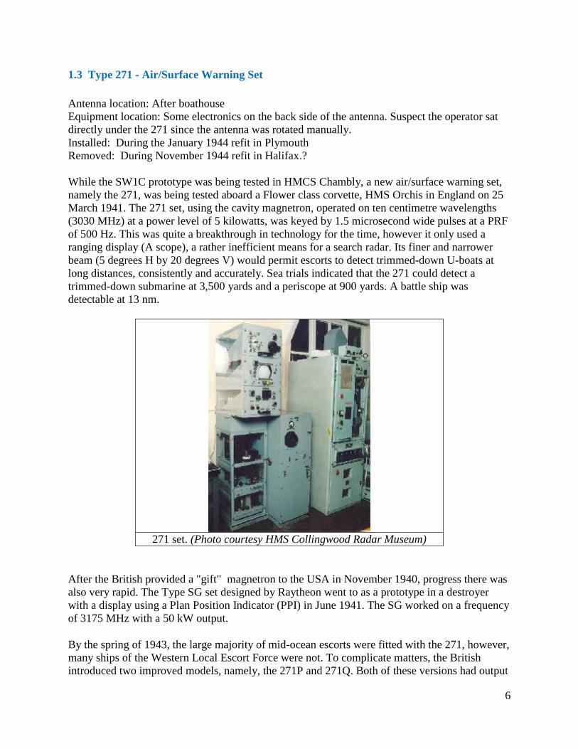
1946 - After bulkhead. 285 receiver. (RCN photo #
1749-73)
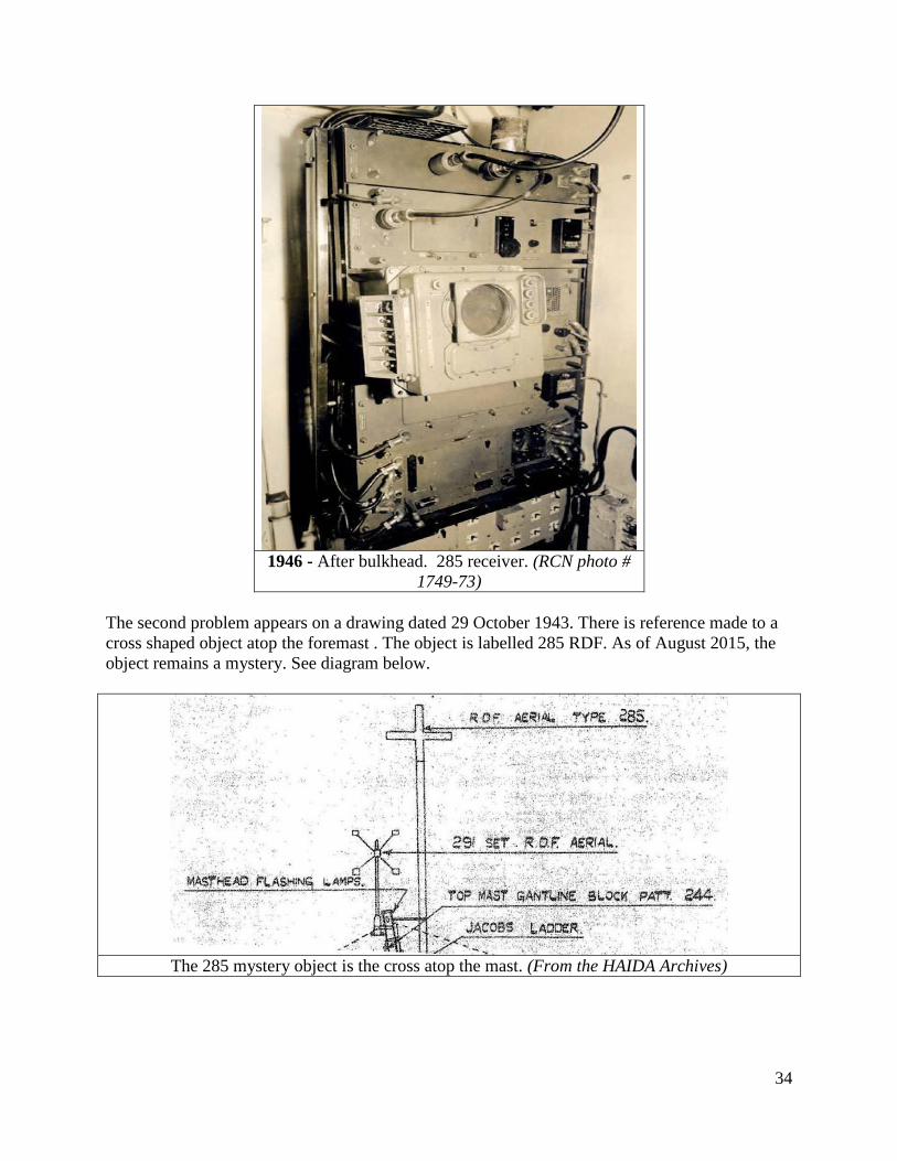
The second problem appears on a drawing dated 29 October 1943. There is reference made to a
cross shaped object atop the foremast . The object is labelled 285 RDF. As of August 2015, the
object remains a mystery. See diagram below.
The 285 mystery object is the cross atop the mast. (From the HAIDA Archives)

35
2.2 AN/SPG-34
HAIDA had two independent SPG-34 antennas and Mk 63 Fire Control Systems.
Antenna locations: One atop ‘B’ Gun and one atop the 3”50 gun.
Equipment location: Forward position - In a separate compartment on the starboard side, Flag
Deck. Aft position - In a separate compartment behind the Armourers Workshop.
Installed: During 1950-52 modernization.
HAIDA paid off with this type.
SPG-34 is an X-band fire control radar for AA guns. It measured the range from the gun to the
target and the value derived was used to calculate the lead-off angle of the gun. The antenna was
a 40 inch diameter dish that could produce a 2.4 degree beam. Power output was 25 to 30 KW
with a range of 25,000 yards.
Side view of the SPG34 radar as fitted on HAIDA's 3"50 gun. (Photo by
Jerry Proc)

36
AN/SPG-34 electronics. (Photo # DNS-24595 courtesy DND, Canadian Forces Joint
Imagery Centre provided via by Robert Langille)

37
3.0 IFF SYSTEMS
The IFF acronym is derived from the words Identification, Friend or Foe. Sometimes it was
called Radar Identification and Recognition System. Starting with the Mk I system in WWII,
IFF initially started with its own separate equipment and antennas and had some limited direction
finding capability. In later developments it was incorporated to work with the main radar search
antenna. Today, the IFF interrogator is embedded in the feedhorn (or a secondary antenna
'bolted' to the parent) of the radar antenna and as the radar sweeps and hits a target it challenges
it at the same time. The operator on the radar set sees an IFF squawk on his PPI. The latest
equipment using the Mk 12 protocol displays all kinds of information to the challenger.
When IFF is being used, the searching radar automatically sends interrogating pulses. This is
accomplished by having the IFF dipole antenna mounted across the opening of the feed horn of
the radar antenna. The IFF unit in a friendly target will automatically respond with the correct
reply and the reply is made visible on the screen of the interrogating radar.
British IFF systems were coded into two series during World War II; the 240 series was used for
interrogators and the 250 series for responders and beacons.
IFF DEVELOPMENTS OVER TIME
MK I AND MK 2 IFF'S
In 1940, the MK I system was introduced in British service. Its details were disclosed to the
United States that fall, but this system was already obsolete. Quite independently, the Naval
Research Labratory (NRL) had developed a pulse transponder in 1939. To challenge, the radar
was switched to a special pulse repetition frequency (PRF) which triggered responses. In US
Service, the CXAMM IFF system was considered equivalent to the British Mk II. So far, the
radar itself was the interrogator. Since the interrogator and transponder operated on the radar
frequency such operation was not satisfactory when many different radars were used.
MK III IFF
The Mk III IFF was Watson-Watt's invention and the precursor of modern IFF systems. IFF
challenge and response were to occupy a separate, specialized band (A-Band; 165 to 185 MHz or
157 to 187 MHz, depending on the reference text). It was adopted as the standard Allied IFF of
World War II and remained in US service for sometime after the war. An important design
criterion was to ensure that the returning signals gave an accurate indication of target bearing and
not merely of target range. The solution was to locate the IFF interrogator on the radar antenna,
rotating with it to give directional indications. The same device would also receive the response.
This was known as an 'interrogator-responsor' system. Mk III was distributed to all Allied forces
including the Soviet Union. From a post-war point of view, it could be considered thoroughly
compromised.

38
Because the system relied on active responses from other ships and aircraft, there were no
problems with sea returns. It was possible to use vertical polarization, thus giving better vertical
coverage. The transmitters also required much less power for a given range so the fitting of IFF
presented few space problems. Initially, the interrogator aerials consisted of directional Yagi
arrays mounted on a horizontal U bar, but in 1944, the most commonly used aerial system
consisted of four, broad-band cage dipoles in a rectangular configuration and capable of powered
rotation.
Reports on the value of IFF varied, according to the theatre of operations. They ranged from
"worked very well" to "never saw it used once in two years at sea."
MK IV IFF
Back in the United States, the NRL designed an alternative system designated Mk IV. It differed
from the Mk III system by employing separate frequencies (470 and 493.5 MHz) for challenge
and reply. Mk IV was generally held in reserve during the war in case the Mk III was
compromised. A few were used in the Pacific theatre at the end of the war. In Europe, it was not
used due to its closeness to the frequency of the German Wurzberg radar that operated at 550
MHz. A German radar operator might discover IFF pulses from Allied aircraft, thus
compromising the system. Due to its higher operating frequency (G-band), Mk IV had greater
directivity and the typical beam width was 7 to 10 degrees.
MK V IFF
Mark III was an interim measure and the NRL was directed to produce a new system that
became Mk V/UNB (United Nations Beaconry). Wider transmitter and receiver frequency
separation permitted the use of higher gain antennas and higher frequencies (950 to 1150 MHz)
made for better directivity. Twelve channels were made available within this range as an anti-
jamming measure. Signals were coded to permit, for example, identification of one among
several 'friendlies'. On a Plan Position Indicator (PPI) display, transponder coding would be
displayed as a dot and dash elongation (radically) of the target pip. The first Mk V systems
appeared in August of 1944 but the system did not complete service evaluation until 1947-48.
Mk V was considered successful but few were produced. Installations were confined to CVB's
and fleet carriers where it was important to be able to track and identify fast targets such as jet
aircraft. As an example, Mk V could identify a jet aircraft flying at 175 mph at 20,000 feet. An
attempt was made to re-design and simplify the Mk V system. It was designated as Mk VI.
MK X IFF
The follow up system to Mk V was Mark X, a system developed in the USA. At first, this did not
mean a jump from the fifth to the tenth Allied IFF system. The X denoted an experimental
system and after it went into production, it assigned the Mk X (ten) nomenclature. There were
problems with the Mk V system. It used a universal 'code of the day' to distinguish friend from
foe but the NRL considered this a serious, potential security risk. Another danger in the Mk V
was enemy use of Allied IFF to identify our own craft. By July 1952, the Mk X system started

39
operational use in 50 per cent of the US Navy. The balance of the fleet was to be converted by
January 1954.
The Mk X IFF system sends a pulsed secondary signal from its Interrogator along with the main
radar signal. This in turn is received by a Transponder situated in the craft under observation.
The Transponder then sends back an appropriate reply that is detected by the Interrogator and
distributed for display. Separate pre-set frequencies are used for interrogation and reply; 1030
MHz for transmission and 1090 MHz for reply. Normally, the IFF antenna will rotate in
synchronism with the main air warning radar thus enabling the responses to be superimposed on
the radar picture.
Three modes of operation are available for General, Personal and Functional identification. The
mode of operation is determined by the spacing between the two 1 microsecond pulses which
constitute the interrogating signals. Spacings employed are 3, 5, and 8 microseconds for modes
1, 2 and 3 respectively. The transponder reply to each of these interrogations is a single one
microsecond pulse except in the case of an aircraft in which the reply to a mode 2 challenge is
two, one microsecond pulses spaced 16 microseconds apart. In addition, the aircraft has the
facility of an emergency reply consisting of four, one microsecond pulses spaced by 16
microseconds between adjacent pulses. A transponder will always reply to a mode 1
interrogation but replies to interrogation in modes 2 and 3 are optional. This is dependent upon
the setting of appropriate switches on the transponder control panel. When set to emergency
mode, the aircraft transponder will transmit the four pulse reply to all modes of interrogation.
MK XII IFF
Mark X did not provide real security. Its interrogation pulse was not coded. There was always a
possibility that an enemy might use Mk X interrogation pulses to induce US aircraft to identify
themselves and then use the aircraft's IFF system as a homing beacon for missiles. As early as
1951, the NRL had developed a vacuum tube binary coder but it was too massive for airborne
use. Transistor technology improved matters. By 1956, an American tri-service group had been
formed to implement what has now become the Mk XII system, the current system in use.
This is a fully cryptographic system so even if the enemy had full knowledge of the system
design, it cannot be used unless the correct interrogation and response codes are known.
Modern day IFF systems are basically Question/Answer systems. An interrogator system sends
out a coded radio signal that asks any number of queries, including: Who are you? The
interrogator system is frequently associated with a primary radar installation, but it may also be
installed aboard a ship or another airplane. The interrogation code or challenge, as it is called, is
received by an electronic system known as a transponder that is aboard the target aircraft. If the
transponder receives the proper electronic code from an interrogator, it automatically transmits
the requested identification back to the interrogating radar. Because it was developed as an
adjunct to the primary echo-type detection radar and is usually used in conjunction with a
primary radar, the IFF system is also known as secondary radar.

40
Modern IFF is a two channel system, with one frequency (1030 MHz) used for the interrogating
signals and another (1090 MHz) for the reply. The system is further broken down into four
modes of operation, two for both military and civilian aircraft and two strictly for military use.
Each mode of operation elicits a specific type of information from the aircraft that is being
challenged.
Mode 1, which has 64 reply codes, is used in military air traffic control to determine what type of
aircraft is answering or what type of mission it is on.
Mode 2, also only for military use, requests the "tail number" that identifies a particular aircraft.
There are 4096 possible reply codes in this mode.
Mode 3/A is the standard air traffic control mode. It is used internationally, in conjunction with
the automatic altitude reporting mode (Mode C), to provide positive control of all aircraft flying
under instrument flight rules. Such aircraft are assigned unique mode3/A codes by the airport
departure controller. General aviation aircraft flying under visual flight rules are not under
constant positive control, and such aircraft use a common Mode 3/A code of 1200. In either case,
the assigned code number is manually entered into the transponder control unit by the pilot or a
crew member.
Altitude information is provided to the transponder by the aircraft's air data computer in
increments of 100 feet. When interrogated in Mode C, the transponder automatically replies with
the aircraft altitude. Ground interrogators normally interlace modes by alternately sending Mode
3/A and Mode C challenges thus receiving continuous identity and altitude data from the
controlled aircraft.
3.1 Type 242M IFF Interrogator (Mk III)
Antenna location: TBA
Equipment location: ?
Installed : On build,1943
Removed: ?
Type 242 IFF series interrogation equipment was fitted on RCN ships in conjunction with Type
291 (and Type 275) radar sets to provide 'A' band interrogation using the standard Mark III IFF
system. Interrogators could function anywhere in the 165 to 185 MHz band, but were normally
used around 179 or 182 MHz (1.8 to 1.6 metres) at a power output of 1 kilowatt. The pulse
repetition frequency was 125 or 50 pulses per second and the pulse length was 6 microseconds.
When used with radar types 291, the 242 was fitted with aerial outfit 'ASD'. This aerial had an
omni-directional radiation pattern. Type 242 was first introduced into service in 1943. The pulse
repetition frequency of the main radar was counted down in ratios of 4:1 or 10:1 in the modulator
which then fired the interrogator transmitter. Simultaneously, a secondary trace, displaced from
the main trace was displayed as an 'A' scope presentation. Interrogator signals received by the
responsor unit were displayed on this secondary trace as inverted signals along with the normal
radar echoes. Correspondence of the interrogator pulse and the radar echo identified the target.

41
The associated shipborne transponder was the type 253 or the Mark III IFF when fitted on an
aircraft. Haida was fitted with the 242WC and 242WS types in the mid 1940's.
Type 242 was used with types 271 (and 275) radar
Type 242M was used with radar types 293 (and 276/277).
Type242P/Q were used with radar sets 960/982/983.
Frequency band: 165 to 185 or 159 to 189 MHz (covers all variants)
242 Interrogator - Component Parts.
1.W4790 responsor unit 2 and 7 are
the AD transmitter 4. W6332
Modulator and mixer. (Photo courtesy
of the British Admiralty)
42
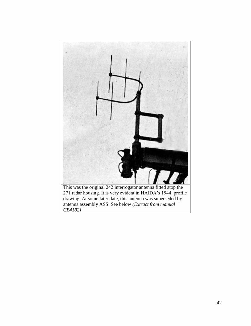
This was the original 242 interrogator antenna fitted atop the
271 radar housing. It is very evident in HAIDA’s 1944 profile
drawing. At some later date, this antenna was superseded by
antenna assembly ASS. See below (Extract from manual
CB4182)

43
Close up view of 242M Aerial Outfit ASS.
(Photo courtesy of the British Admiralty)
Aerial Outfit ASS on HAIDA during her first
tour of duty in Korea. (Photo courtesy RCN)

44
3.2 Type 253P Transponder
Antenna location: TBA
Equipment location: ?
Installed : On build in 1943
Removed: When the IFF MK X system was installed.
Type 253P was a shipborne transponder, compatible with the Mark III IFF system and operated
in response to triggering pulses from any interrogator or radar set in the same frequency band.
When triggered, Types 253P/Q responded with various coded signals as required for the
purposes of normal interrogation or ship-to-ship identification or homing. This set could operate
in the 157 to 187 MHz band but normally operated at 182 MHz for ship-to-ship identification or
when used as a beacon facility. In a normal fit, aerial outfit 'ASH' was used. For installation
aboard coastal craft, aerial outfit 'ANT' was used. Normally the power output was 10 watts. A
low power setting of 0.75 watts was available as an anti-direction finding measure. The pulse
repetition frequency was triggered by the receipt of signals from interrogators of radar sets. This
was limited only by a 300 microsecond period of quiescence between each transmission. The
pulse length of the output signal could be set for narrow (6-10 us), wide (17-25 us), or distress
mode (80 us).
Types 253P and 253Q were similar except that type 253Q was mounted in a resilient steel
cabinet. By operating the buttons marked 'I', 'A', and 'B' on the code selection unit, the following
operating conditions were permitted:
I: Normal Mark III IFF responses (sweeping 157-187 MHz every 2.8 seconds). Six codes were
available by selection and each code consisted of four transmissions using narrow and wide
pulses. A complete code was transmitted once every 11.2 seconds. A special extra wide pulse
was available for distress purposes.
A: Alternate normal IFF codes consisting of four narrow pulses for 5.6 seconds followed by 5.6
seconds of Identity Code on a fixed frequency of 182 MHz. This code consisted of two letters
that could be of any combination of nine narrow, wide or blank pulses which were selected by
means of the nine switches on the Code Selection Unit.
C: Chopped response on the frequency of 182 MHz. The response was mechanically interrupted
for 40 milliseconds every one-fifth second to distinguish it from a normal code.
To limit mutual interference, the antenna for type 253P was situated at least 12 feet or more from
the nearest interrogator antenna on a ship. Haida was fitted with the type 253P transponder
during the mid 1940's.

45
253 Transponder component
parts (Image courtesy of the
British Admiralty)
3.3 AN/UPX-1A IFF SYSTEM (Mk X)
Antenna locations: One antenna on port and one on the starboard side of lower yardarm on the
foremast.
Equipment located: In a rack in the EMR compartment .
Installed: Believed to be 1958, when the EMR was created.
HAIDA paid off with this type.
When HMCS HAIDA paid off, her Mark X IFF fit is listed below. Most of the equipment was
fitted in the EMR compartment while it was in service. All that remains today of the original
system is a single AS-177 antenna on the foremast yardarm and a C1008/UPA-24 box which was
located after 1992.
UPX-1A SYSTEM COMPONENTS
* AN/UPA-24 /KY80 IFF Video Decoder
* AN/UPA-24 /C1008 Radar Set Control (in Operations Room)

46
* AN/UPX-1A /RT-194A IFF Receiver-Transmitter (for IFF dipole in front of SPS-6C feed
horn)
* AN/UPX-1A /KY-61A IFF Coder/Decoder
* AB-274 IFF Dipole antenna assembly in front of SPS-6C feed horn
* AN/UPX-5 /RT-269 IFF Receiver-Transmitter (for dedicated IFF antenna on foremast
yardarm)
* AN/UPX-5 /KY-88 IFF Decoder
* AS-177 Antenna Assembly (dedicated to UPX-5). 1090 MHz TX/ 1030RX
* AN/UPM-99 Radar Test Set
* AS-177 Antenna Assembly (dedicated to UPM-99)
These devices were shown on the ship's drawing as intentions but were never installed:
* AN/UPA-38 /KY-136 Video Coder
* AN/UPA-38 /C1407 Radar Set Control (in Ops Room)
The AS-177 antenna aboard HAIDA. The
outer shell has been weatherworn, thus
exposing the fibreglass base material. (Photo
by Jerry Proc)

47
UPA-24/C1008 Control. This
was the control box for the
group video decoder. Located
in the Ops Room, it
controlled the mode of
transmission ( ie mode 1, 2 or
3) and the 'squawk' code
assigned to each particular
ship. (Photo by Jerry Proc)
KY-61/UPX-1 This was the IFF Coder/Decoder(Photo courtesy Destroyer Escort Central)

48
RT-194/UPX-1 . This the IFF interrogator. Comprised of a receiver/transmitter whose output
connects to the IFF dipole in front of SPS-6C feed horn. (Photo courtesy Destroyer Escort
Central)
SPECS: Tx Freq. 1090 MHz, Rx Freq.1030 MHz. Average power - 1 kw. using Modes 1, 2
and 3. Mode 1 and 2 was a Naval and Air Force mode. Mode 3 was also a airborne civilian
mode. The UPX-1 transmitting mode was also controlled by the AN/UPX-24".

49
Haida's IFF Interrogation Initiation System (Drawing by Jerry Proc)

50
Haida's IFF Interrogation/Response System
3.4 AN/UPM-99
This was the IFF test set used to test the Mk X IFF system. The UPM-99 simulated the responses
of aircraft transponders, and in doing so, the shipboard technicians could verify the correct
operation of the UPA-24/C1008 decoder for each radar display fitted with IFF. The safety of the
ship depended on this equipment for if the aircraft in question did not respond with the right set
of codes it would be declared as hostile.
Radar Test Set AN/UPM-99 is designed for testing and performing corrective maintenance on
IFF equipment of both the Mark X and SIF (Selective Identification Feature) type. It can also be
used for making various tests required for maintenance of other radar equipment operating
within the 925 to 1225 MHz frequency range.

51
The entire test set incorporates 88 vacuum tubes and 72 solid state diodes and was introduced in
1960. It was intended for HMCS HAIDA but was never fitted.
From bottom to top: PP-2391 Power Supply; SM-189/UPM99
Code Simulator ; TS-1253-UP Radar Test Set; CY-
1156/UPM-4 Accessory Box. The TS-1253 unit can function
separately since it has an internal power supply and
incorporates the functions of a precision oscilloscope and SlF
code generator. (Image credit unknown)
52
4.0 ASDIC/SONAR SECTION
INTRODUCTION
The first device used to locate submarines is called Asdic (named after the Anti-Submarine
Detection Investigation Committee) and was invented during World War I by British, American,
and French scientists. This system located underwater objects by transmitting an acoustical pulse
of energy, then listening for any echoes returned from that object. From ASDIC, the more
modern term SONAR was borne, which means SOund NAvigation and Ranging. SONAR is an
American term dating from World War II and is now used universally to describe all underwater
detection equipment. In the RCN, the term SONAR started coming into general usage around
1955 and in the Royal Navy, around 1964.
A problem with early Asdic's was their limited search ability as the oscillator projected its cone
shaped beam at an angle of 10 degrees from the horizontal. Below the beam of acoustical energy
was a considerable amount of dead space that would permit the target to elude Asdic. If the
enemy escaped detection, depth charges had to be dropped by estimating the target's position.
Wartime experience showed that this dead zone was even larger than envisioned because
submarines could dive far deeper than was originally thought possible. As a result, a clever
submarine commander could often manoeuvre out of harm's way. Once contact was lost, it was
very difficult to re-establish.
When operating in conjunction with other detection ships, it was very important that all the
operating Asdic's were tuned to different frequencies. If an operator was negligent of this, a
transmitted pulse from another ship's Asdic would be detected as an extremely loud echo on
another set. The operators' ears would experience the threshold of pain as the amplified echo
thundered in his headphones. The Asdics developed during the war operated on a number of
discrete frequencies between 14 and 22 KHz. Power output of oscillators was inversely
proportional to the operating frequency. Many operators favoured operation in the 14 to 15 KHz
range because they believed that greater ranges could be obtained as contrasted by operating at
18 to 20 KHz. It was well known that greater ranges could be had at 10 or 12 KHz, but that
meant increasing the oscillator size. It was a trade off.
Asdic set designs generally fell into one of two categories depending on the type of Asdic dome.
In the first type, the oscillator was housed in a dome fixed to the bottom of a vessel near the bow.
The second type was housed in a retractable dome that could be positioned inside a chamber
built into the hull of a vessel. Normally, this last type was fitted into vessels whose operations
could damage an unretracted housing. Destroyers, which could damage their domes while
operating at high speeds, and minesweepers, which could foul Asdic domes with their sweeping
gear, were typically fitted with a retractable dome. To protect Asdic sets from ice damage, the
RCN decided to fit all new vessels with retractable domes in mid-1942. When the dome was in
the housed position, it precluded using Asdic. Corvettes, Fairmiles and converted yachts that
only incorporated the most basic of necessities, did not have retractable domes. As a result, many
of these ships sheared their domes by striking logs or chunks of ice off the coast of

53
Newfoundland. These fixed installations were not very successful but it was better than not
having any system. When corvettes discovered a U-boat lurking in the depths, it became practice
for the corvette to try to drive the U-boat underwater where it was slow and nearly blind, then
return to the convoy. Trying to overtake the U-boat was pointless since the surface speed of the
U-boat was slightly higher than that of a corvette. Later on, design improvements produced a
sword shaped oscillator whose physical appearance resembled that of a sword and the angle from
the sword to the bow could be altered to detect deep targets. In some Fairmiles, the oscillator was
fixed to the hull and to train it on a new bearing, the ship would have to be turned. The standard
procedure was to steer on the contact while altering course in a cast off fashion and back on
again until the ship was able to drop depth charges.
From its inception in 1917 until the late 1940's, the detection range of Asdic remained at
basically 2000 yards. True, during World War II, there were refinements in fire control and depth
measurement, but the range remained much the same. If conditions were ideal, a target at a range
of 3000 to 4000 yards could be detected and but that was the absolute limit. Contrast this to
today's hydrophone technology that can detect the propeller noise of a diesel electric submarine
at distances of 100 nm. A modern system can also identify the class of submarine by comparing
the hydrophone signal to a pre-loaded signature in the memory of a computer. Tactically, an
Asdic that only produced a narrow beam was very useful for attack, but not for search, since it
could not look rapidly in many directions. It was not until the end of World War II that 'true'
search sonar was introduced into the world's navies.
ASDIC OPERATIONS ABOARD HMCS HAIDA
Wilf Knecht of Nanaimo, British Columbia was a former Asdic rating and he provides an
impression of Asdic operations aboard HMCS Haida during the 1944/45 period."A normal duty
watch consisted of two operators manning the equipment. The Asdic recorders were located in a
cabin below the bridge, on the port side and off the plot room. Under normal conditions, one
rating operated the Asdic and communicated with the bridge using voice pipe while the other
stood by. Both operators took turns in the active position.
When Action Stations were sounded, three operators sat on a bench in front of the Asdic and
actively manned it. An HSD (Higher Submarine Detector) monitored the proceedings. On the
left side of the bench, sat an operator who read out the bearing if a contact was acquired. Any
rapid change or loss of bearing also had to be reported to the bridge. The centre operator
operated the training control, raised and lowered the dome and controlled the firing of the depth
charges. The right most rating would operate the range finder. A gyro compass repeater was
provided for use by the middle operator and a magnetic compass was also fitted in case the gyro
failed. When using a magnetic compass, a stop watch had to be used to establish range.
When leaving or entering harbour, the Captain or Officer of the Watch would inform the Asdic
hut when to lower or raise the oscillator dome. It had to be raised if Haida was steaming above
20 knots or dome damage would result. Sometimes this was forgotten by the bridge and the
Asdic operator would have to request permission to raise the dome. Operators did not search the
sea at random. The normal search procedure in most cases was given as: set range to 2000 yards
and begin search from Red 30 degrees to 5 degrees past the bow. If no echo was returned on the

54
given bearing, the operator would search from Green 30 degrees to 5 degrees past the bow. This
sweep was repeated until ordered otherwise or a contact was made. If a contact was made, the
range recorder operator would reduce the automatic transmission time to eliminate the lag time
between transmissions as the target drew closer to the attacking vessel.
Every contact had to be classified for type, distance, direction and be reported to the bridge
immediately. Operators had to be aware of the Doppler effect, which is a change in pitch of the
echo as the target moved closer or more distant. The operator had also had a chance to
demonstrate his skills in determining if an object was a whale, tide or water conditions, large
schools of fish, rock formations or old wrecks." One point that Wilf highlights is the fact that
there was no documentation issued to Asdic ratings due to the prevailing level of secrecy. Jim
Fairnie of Victoria B.C. recalled another side to this secrecy. "Asdic operators were prohibited
from wearing Asdic badges on uniforms while at sea in case their vessel was torpedoed and they
were picked up by the enemy. To add to the disguise, the operators wore a torpedoman's badge."
Because Asdic transmissions were audible by their nature, operators had to wear headphones to
hear the incoming echoes. Since it was also necessary to communicate with the bridge, the
operator could not keep both ears covered so the one earpiece was placed against the side of the
head and then switched occasionally. If a contact was acquired during Action Stations, its echo
could be patched into the ships loud hail to keep everyone informed as to status. When not
operating Asdic, operators would be assigned to the plotting table or the depth sounder."
John Coates explains his role in Haida's Asdic room. "In action, I took up my station behind the
operators and wore my chest set. This was merely a set of headphones and a chest microphone.
One earpiece was wired to monitor the contact and the other was connected to the bridge/ops
room circuit along with the microphone. There was an extra long lead on the headset so I could
step around the corner and see the Plot.
If I wanted the most current contact status from any of the operators, I would touch them on the
shoulder as part of an established drill. We did keep a continuous flow of bearing and range
information to the bridge and the Plot and consciously kept the verbal chatter to a minimum.
Rear Admiral Bob Welland (Ret'd) of Ottawa Ontario, relates some of his wartime experiences
as CO of Haida and Assiniboine. "The CO's of the ships in a squadron or group got to know each
other well and usually had opportunities to discuss the last operation and the up and coming one.
We also compared our habits at sea. For instance, I stayed up at night because that's when the
action happened and I knew that the Officers of the Watch could handle the situation in daylight.
Also, I never got undressed except to wash up. I arranged an Asdic gyro indicator to be fitted in
my sea cabin along with a speaker that pinged if an echo was detected. Upon hearing an echo, I
would wake up and using the voice pipe, I would have the ship turning before making it up the
ladder to the bridge. I was not alone in this. Many of the senior operators and the HSD's slept in
the Asdic office for the same reasons.
Over time, it got to the point where the CO's of various ships created a 'pool' and took bets as to
which ship would be torpedoed or be in collision. I won twice but had to share the pot with
another Captain."
55
4.1 SONAR INSTRUMENT SPACE
All the Sonar/ASDIC electronics was located in this space. Transducers were situated in the
Hull Outfit 7A. Indicators and controls in the Sonar Control Room and one type 164 indicator in
the Operations Room.
4.2 Type 144Q Search Sonar
System installed: On-build in 1943
System removed: Likely during 1950-52 modernization.
HAIDA'S equipment manifest of the mid 1940's lists the installation of the 144Q Asdic set. Both
the 144 and 145 sets were designed to be used with ahead throwing weapons such as Hedgehog
but could easily be used with depth charges. This new development in Asdic technology made its
service debut in May of 1943. The main features of the 144Q set are described below.
The Q attachment was an additional Asdic set which required separate transmitting and receiving
equipment suitably inter- connected with the main set. Physically, the Q oscillator was mounted
beneath the main oscillator and trained with it. It projected a fan shaped beam that was narrower
in the horizontal plane than the main Asdic beam but sufficiently wide in the vertical plane to
receive echoes at any angle from the horizontal to 45 degrees below horizontal. The beam was
only 3 degrees wide on the horizontal plane. Collectively, this new arrangement enabled contact
to be maintained with deep targets at short ranges and also minimized the dead zone. The Q
beam was transmitted through a window in the bottom part of the dome.
This arrangement allowed the Q oscillator to be used at angles of up to 70 degrees from the bow.
In shallow water, the Q beam would strike the bottom giving long drawn out echoes that
appeared similar to heavy reverberations. This effect made the Q beam appear stronger than the
main beam but the effect disappeared in deep water.
Range
The transmission range was selectable between 1000 and 2500 yards.
Frequencies
The main set could operate at any one of a series of fixed frequencies. In KHz as listed:
Y 14
A 15
B 16
C 17
D 18
E 19
F 20
56
G 21
H 22
The Q attachment operated at 38.5 KHz. To avoid mutual interference between the main set and
the Q attachment, the two transmitting circuits were synchronized so that they transmitted
simultaneously. During reception, Doppler shift was much more pronounced on the Q beam as
opposed to the main beam.
Oscillator
The Q oscillator was rectangular in shape, completely encased in rubber, and its dimensions were
12.5 inches long by 2 inches wide and 2 inches thick. Within the dome, the oscillator was
mounted so it faced downwards at a fixed angle of 15 degrees.
Transmitter
The key operating circuit was completed by the range recorder or by Morse key. Alternately, the
circuit could be closed if the send-receive key was moved to the 'Send' position. This action
connected the oscillator by way of the tuning panel to the high frequency motor-alternator. A
high frequency alternating current was then applied to the oscillator which in turn sent a
transmission. The transmission ceased immediately when the key operating circuit was broken.
The motor-alternator set that provided the high frequency current for the oscillator, consisted of a
110 or 220 volt motor driving an inductor type alternator over a range of 4,666 to 7,333
revolutions per minute. This corresponded to a frequency range of 14 to 22 KHz. Dual motor-
alternators with a change over switch were fitted to allow for maintenance on one unit while the
other unit was on-line.
Oscillator frequencies were changed by opening a control box near the motor and moving the
'wandering' lead marked F (field) to a different resistance tap. The selected tap would either
speed up or slow down the motor thus changing the output frequency of the alternator. The
output was then fed to the tuning panel that consisted of an inductor, a capacitor and resistor.
These components formed a resonant circuit that effectively stepped up the output voltage of the
alternator to the 2000 volt level required by the oscillator.
It is estimated that the output power of the transmitter was in the range of 300 to 500 watts. The
tuning of the receiver to match the actual transmitted frequency was most important - and the
facilities to do that were not easy to understand and execute in practice.
Dome
In the retracted position, the dome protruded eleven inches below the keel and was four and a
half feet below the keel when extended. A two horsepower motor was required to raise and lower
the dome with a provision to do it manually. A set of indicator lamps in the Asdic office
indicated the position of the dome -- red was for the working position, green was for housed and
red/green for any intermediate state. In the housed position, the dome, the raft, and the oscillator

57
were drawn up to the top of the trunk. The top of the raft butted up against a dermatine seating
ring under the top of the trunk, thus making a watertight joint. This allowed the portable cover to
be unbolted, in the event that either of the oscillators had to be changed. The procedure would
only work if the dome was undamaged.
The Staybrite window of the dome, was aligned with the face of the oscillator so sound waves
could be transmitted and received in a 360 degree arc in 5 degree steps. Staybrite was secured
over a ribbed section of heavy cast metal and this ribbing is what produced the window effect.
Both fixed and retractable domes used Staybrite windows.
Maximum design speed for the dome was 25 knots but on Haida, the maximum working speed
was 20 knots. When retracting or extending the dome, it was necessary to check the voltage of
the mains supply. In a 220 volt mains' system, the voltage could not drop below 180 volts. If it
did, the contactor in the control board could fail to operate thus causing the dome to bump
against the end stops and cause damage.
The dome was normally housed for any of the following conditions: when working cables; when
working bottom lines; when entering or leaving harbour; when steaming into a heavy sea; if
cessation of Asdic operations could be tolerated; and finally, when navigating in shoal water and
Asdic is not required for navigation.
AVC Receiver
The Automatic Volume Control (AVC) receiver was a rack mounted, seven tube heterodyne-
amplifier, operating in the 10 to 26 KHz range. Any received sound would disturb the oscillator
which in turn produced a weak voltage fluctuation across its terminals. This voltage was then
applied through the tuning panel and the send- receive key to the input of the AVC receiver
where it was amplified and heterodyned. The A.V.C. output was then fed to the Very/Quick
(V/Q) changeover board. Here, the signal could be distributed to the recorder, the loudspeaker,
the telephone switches or any combination of these.
Why was an AVC receiver required? When reverberations were received and were extremely
loud, they drowned the echo. To overcome this problem, automatic volume control was used.
Such an amplifier reduced the amplitude of loud sounds and amplified weak sounds thus
producing a 'smoothed out' effect. This in itself is problematic, because echoes would not be
distinguishable from reverberations. To overcome the second problem, the amplifier was
designed to prevent the AVC from functioning whenever a loud sound was received. This
allowed the echoes to escape the smoothing process and made to stand out very clearly against
the long (and consequently reduced) sound of the reverberations.
Within the AVC receiver, there was an electronic oscillator whose output signal was mixed with
the incoming signal. This is known as the heterodyning process. In the 144Q set, the difference
between these two frequencies was 1000 cycles per second. This tone was then passed to the
range recorder where it generated a mark on a strip of paper.

58
Range Recorder
This instrument was designed to visually record sounds received by the oscillator and provide an
accurate range plot on paper. At the appropriate time, as determined by adjustments made to the
recorder settings, it automatically actuated the release of depth charges or the firing of ahead-
thrown charges.
144Q Range Recorder. (Photo courtesy of the British
Admiralty)
Specially treated paper was driven by a gear mechanism and marked with a stylus. This paper
was impregnated with a solution of potassium iodide and starch. Passage of electrical current
through the paper from stylus to roller released 'free' iodine. The iodine was then deposited on
the paper thus making a record in the form of a brown mark. When installing fresh paper records,
it was imperative to minimize the amount of time that the paper was exposed to air. Within the
recorder, the paper roll was stored in an airtight container known as a tank. Each roll of paper
was 30 yards long and a black warning mark would appear on the right hand edge signifying the
approach of the end of the roll. After its appearance, there was still sufficient paper remaining to
complete the attack. Alternately, yellow coloured, cadmium-iodide paper could be used in the
range recorder. Generally speaking, the range recorder was only switched on when investigating
a contact and during attack.
The recorder also had a paper speed switch which had two positions. - Cruising and Attacking. In
Cruising , the paper moved slowly, just fast enough to give a clear space for the stylus to mark
on. In Attacking mode, the paper moved at a faster speed. The object of the switch was to save
paper by providing a slow paper speed when sweeping. When sweeping was initiated, the range
recorder operator had to see that the paper speed switch was set to cruising. On gaining contact,
the switch was set to Attacking .

59
To summarize, the range recorder has two jobs. One is to make the transducer train and transmit
when it should. The other is to mark the echoes on the paper and indicate the time to fire the A/S
weapon. The recorder is fitted with control switches. They are the barrel switch with four
positions, the scale change switch and the paper speed switch. It also has a handle to adjust the
transmission interval.
Bearing Recorder
This instrument indicated the gun bearing when carrying out an ahead-thrown weapon attack
against a submarine. An adjustment was provided to make allowance for ship's own speed and
the sinking time of the charges. The bearing recorder was used in conjunction with the range
recorder from which it obtained the necessary impulses for the paper drive motor.
144Q Bearing Recorder. (Photo courtesy of the British Admiralty)
Operating the 144Q Asdic
Harry Carson provides a detailed explanation on the operation of the 144Q stepping switch. "The
stepping switch was a spring loaded, stepped switch, mounted in the centre of the training wheel.
When the switch was moved to the right, it would train the oscillator to the right. If the switch
was released by the operator, the training mechanism would reverse the direction of rotation and
set the oscillator to the same angle as the switch setting. The oscillator would be kept in that
direction until the operator heard an echo. At this time, he tapped the switch and continued to do
so each time an echo was heard. The oscillator would then be trained off the contact by the
control mechanism until the First Operator would receive no echo. Next, the stepping switch was
reversed and the training mechanism would reverse direction. The Operator would then tap the
switch sharply when the echo was heard. Again, the stepper switch would be reversed and

60
repeated until the bearing 'cut-on' could be determined. Additional repetitions of this procedure
allowed the operator to determine right cut-on, left cut-on, extent of target and bearing
movement. This data along with information on the echo Doppler would be reported to the
bridge.
In the Operations room, the data was plotted on the A.R.L. Plot in preparation for the depth
charge attack. If the echo was lost and the 'lost contact' procedure failed to relocate the echo, the
A.R.L. Plot would assist the Anti-Submarine Officer (A/S C.O.) in estimating the position of the
sub based on the A.R.L. Plot layout. The A/S C.O. would then give the operator a new sector to
search. This would still not guarantee that the contact would be found as both the hunter and the
hunted may have gone around in circles."
This pictorial illustrates the shape of the detection area for the 144 ASDIC, the 'Q; attachment
and the 147 ASDIC. (Graphic courtesy of Destroyer Escort Central)

61
4.3 Type 147B Depth Finding Set
Supplement to Type 144Q
System installed: 1943?
System upgraded to 147F during 1950-52 modernization ?
The 147 type was a depth finding set that complemented the main Asdic set (144Q and the Q
attachment. It's most notable feature was its sword shaped oscillator operating at a frequency of
50 KHz. Physically, the sword was four to five inches wide and approximately four to five feet
long. To prevent interference with the main set, the 147 was mounted ahead of it. When not in
use, the sword was stored in a lifting tube mounted within the hull. When deployed, the sword
could project a fan shaped beam being narrow in the vertical plane and wide in the horizontal
plane. It could be trained up to 65 degrees horizontally and 45 degrees vertically. This new
design, which added depth determining capability, could accurately track a target within 20 feet.
Another feature was its integration with Squid, an ahead-throwing Anti-Submarine (A/S) mortar.
Together, they formed the most effective A/S weapons system of World War II. When an echo
was received on a 147B set, the operator would tilt the sword until the echo was lost. He would
then reverse the procedure until the echo was heard again, then continue sweeping until the echo
was lost on the opposite end of the sweep. Every echo received would then be printed on the
depth recorder. A line of light on the depth recorder would indicate the centre of the echo trace.
The operator would then look at a calibrated scale and read off the depth directly in feet. From
here, the information was used for setting the pistols on depth charge fuses or transmitted to the
Squid mount. When Hedgehog was fitted, depth information was not applied, since this weapon
had to strike a solid object before it exploded.
New style recorders automatically gave range and direction for steering, while the set itself could
automatically set and fire Squid mortars. After the war, it was calculated that a well trained 147
team could achieve a 50 per cent kill rate, nearly nine times that of depth charge system and
substantially more than Hedgehog. The 147 set was first tested in March of 1943 and entered
service with the Royal Navy in September of that year. It cannot be ascertained when the RCN
was informed of this new Asdic type, but discussions for procurement of the 147 did not begin
until September of 1943. Eventually 150 of these sets were ordered with the intention of
eventually retrofitting all RCN escort ships. A 147F set was fitted on Haida and was
complementary to the 164B attack sonar.
Harry Carson also adds, "While serving in HMCS Haida from March 15, 1952 to September 24,
1953, the sonar on board was not used extensively in the Korean Campaign as the North Koreans
had no submarines. Gunnery was the major weapon of this war although we swept for
hydrophone effect especially when sighting Junks along the coast."

62
This photo illustrates the opening for the 147 set. The photo
was taken when HMCS HAIDA was in drydock in
2003.(Photo by Jim Brewer)
Type 147F Depth Finding Set.
Used in conjunction with 164B set
System installed or upgraded: ?
HAIDA paid off with this type
4.4 Type 162
Notation found on 1952 HAIDA drawing along with 147B set.
System installed: ?
System removed: ?
The book “Seek and Strike” describes the 162 as a bottom contact classification set for detecting
submarines or bottom wrecks. See AN/SQS-501.
4.5 Type 164B Range and Bearing Finding Set
Used with Ahead Throwing Weapons such as Squid.
System installed: ?
HAIDA paid off with this type
This Asdic set was mainly fitted into frigates and Tribal class destroyers and designed to be used
with Hedgehog or Squid (mortar bomb). It incorporated a quartz transducer and the Q2

63
attachment that is well documented in the 144Q section. In many ways, it was very similar to the
144Q set. The type 164 was a range and bearing finding device that was supplemented with
depth data from the 147F set. If fitted on a frigate, then Hull Outfit (dome) number 3 would be
used. For Tribal Class destroyers, Hull Outfit 7 or 7A was used. On Haida, both the 164 and
SQS-10 transducers were fitted into Hull Outfit 7A. The type 164 bearing repeater was a large
mechanical indicator with bearing pointers.
Type 164 range recorder. (Courtesy of the
Collingwood Collection).

64
Type 164 Bearing Recorder. (Courtesy of the
Collingwood Collection).
4.6 AN/SQS-10 Search Sonar
System installed: During 1950-52 modernization
HAIDA paid off with this type
The AN/SQS-10 sonar was called an azimuth scanning AM type since it transmitted and
received omni-directionally. When HMCS Haida was paid off, she was fitted with this sonar
type, so it will be discussed in greater detail. SQS-10 sonar was granted 'AN Nomenclature' type
number in 1950 and manufactured by Sangamo Electric. Unlike the wartime Asdic sets, this unit
did not use a quartz oscillator. Instead, it was replaced with a transducer -- a device that produces
underwater sound based on the magnetostriction principle. Unlike the 2000 yard limit of the
wartime Asdics, this set could operate out to 6000 yards under ideal conditions when echo
ranging.
What is Magnetostriction?
When an iron rod is placed inside a coil and a direct current (DC) is passed through the coil, the
iron will lengthen. This is known as an electromagnet. If the current is reversed, the rod will
again lengthen. By substituting alternating current (AC) the rod can be made to vibrate at twice
the applied frequency. The amount of lengthening is also dependent upon the material used and
it's magnetization properties.
To overcome the doubling effect, a DC polarizing current is applied to the coil. This causes the
iron rod to lengthen and stay lengthened by a certain amount. If AC is applied on top of the DC,
the rod lengthens even farther during the positive half cycle but returns to its normal length
during the negative half. The frequency of the applied AC is selected to be close to the natural

65
resonant frequency of the rod. By bundling multiple electromagnets and attaching the ends of the
rods to each of two plates, a pulse of sound can be produced. One plate, which is thicker than the
other is known as the base and the other plate is called the diaphragm.
Research indicated that nickel was an ideal material to use in the construction of a transducer
since it has a characteristic to retain residual magnetism. This magnetism assists with the
production of the polarization field. An alternate method to manufacture a transducer would be
to use laminated nickel-iron stampings instead of rods. Each of these electromagnets was called a
stave or an element.
Transducer Construction
The SQS-10 transducer was cylindrical in shape and operated on the magnetostriction principle.
Externally, the transducer is covered with a heavy rubber jacket or boot to keep the internal
elements watertight. Electrically, it was two transducers in a common housing. The SEARCH
section consisted of 48 vertical staves arranged into four sections. Each stave contained nickel
laminations and a polarizing magnet and was electrically independent of the others. Located
directly above this array of staves was a second ring of staves that formed the second transducer
within the common housing.
This second transducer was used for echo ranging when the target was too deep or too close and
the ship was about to pass over it. Since this second transducer permitted the target contact to be
held until the last moment, this transducer was called the MAINTENANCE OF CLOSE
CONTACT (MCC). The MCC mode was switch selectable from the operator’s console.
There was no need to rotate a transducer of this type since the 48 staves covered an arc of 360
degrees. When training the audio system to the bearing of the target, it was a case of simply
enabling the staves on which the returning echo or hydrophone effect was the loudest. This was
done with the audio scanning switch. A transducer transfer switch selected the normal or MCC
portions of the transducer.

66
Cut-away view of the SQS-10 transducer. (Courtesy of the RCN)

67
SQS-10 COMPONENTS
SQS-10 major component listing. (Graphic courtesy Sangamo Electric Company)
AF/RF Amplifier (AM-580/SQS-10)
The primary purpose of the AF/RF Amplifier was to amplify the audio frequency or radio
frequency signals received from the 48 staves of the transducer and pass them across the audio
and video scanning switches. In addition, the unit contained the keying relay, also known as the
send/receive key.
Receiver Scanning Switch Assembly (R433A/SQS10)
This was a cabinet that contained a three channel receiver, the master oscillator and the
audio/video scanning system. Pulse lengths from the oscillator were adjustable for 7, 35 or 100
millisecond intervals. One channel of the three channel receiver was used for the audio signal.
The other two were used as a twin channel receiver for the video portion of the system. A sum-
difference switch on the operators console determined whether they acted as two separate
receivers or as one. This affected the display on the CRT mounted in the operator’s console. In
sum, any echo or noise will brighten, but as only as a large mass. If switched to difference, a
sharp, clear spot was displayed.
The video scanning switch differed greatly from the audio scanning switch. It consisted of 48
staves rotating at 3000 revolutions per minute, thus giving 9000 scans per minute. Its rotor was
divided into a right and left half which permitted the twin channel receiver to be used as either a
single unit, or as two separate receivers. Through means of a 2:3 gearing ratio, the rotor was
connected to a sweep generator. This generator controlled the rotation of the spot on the cathode
ray tube and also the distance that the spot moved from the centre to the outer edge of the CRT.
Visually, a small blotch of light was produced at the centre of the CRT and blossomed out into a
circle by the time it reached the edge of the CRT.
Transmitter (T318-SQS10)
This assembly contained the power amplifiers for the transducer when echo ranging was used.
The 20 KHz signal produced by the master oscillator was amplified and connected to the
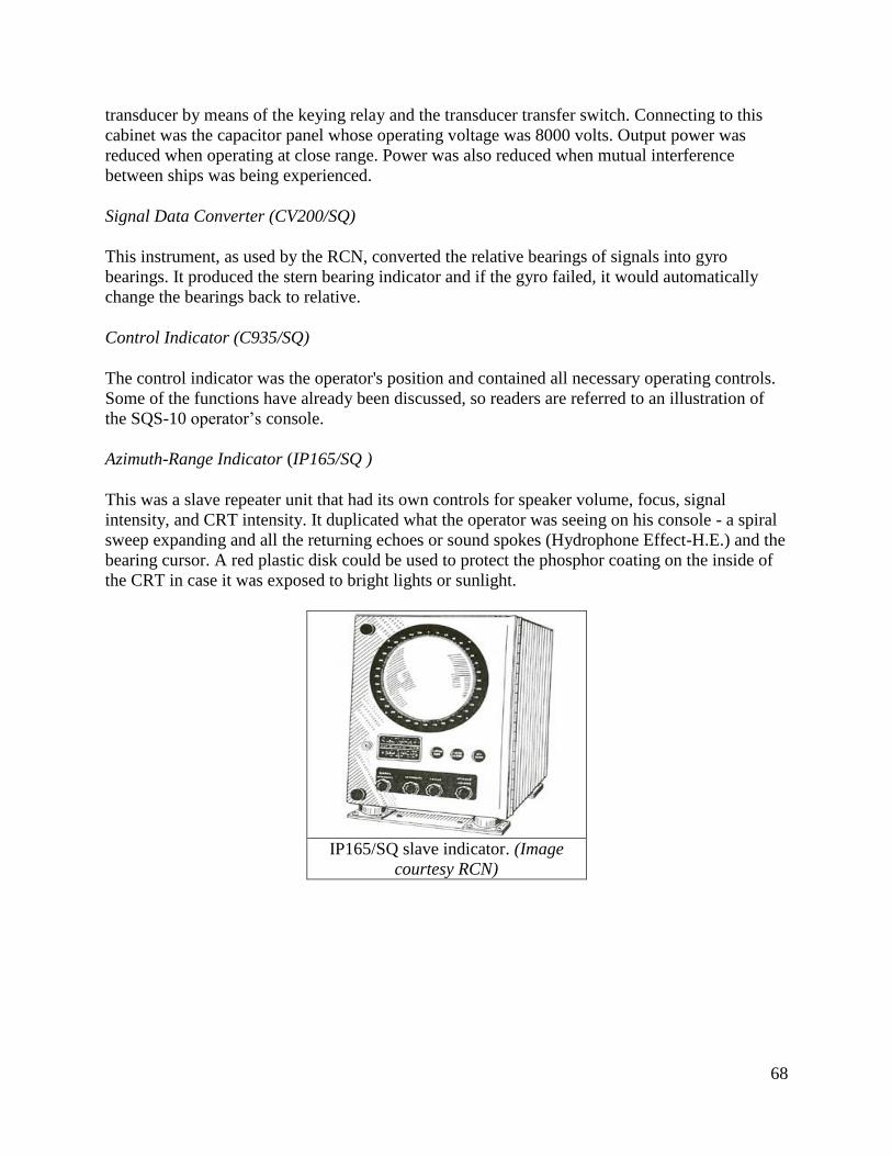
68
transducer by means of the keying relay and the transducer transfer switch. Connecting to this
cabinet was the capacitor panel whose operating voltage was 8000 volts. Output power was
reduced when operating at close range. Power was also reduced when mutual interference
between ships was being experienced.
Signal Data Converter (CV200/SQ)
This instrument, as used by the RCN, converted the relative bearings of signals into gyro
bearings. It produced the stern bearing indicator and if the gyro failed, it would automatically
change the bearings back to relative.
Control Indicator (C935/SQ)
The control indicator was the operator's position and contained all necessary operating controls.
Some of the functions have already been discussed, so readers are referred to an illustration of
the SQS-10 operator’s console.
Azimuth-Range Indicator (IP165/SQ )
This was a slave repeater unit that had its own controls for speaker volume, focus, signal
intensity, and CRT intensity. It duplicated what the operator was seeing on his console - a spiral
sweep expanding and all the returning echoes or sound spokes (Hydrophone Effect-H.E.) and the
bearing cursor. A red plastic disk could be used to protect the phosphor coating on the inside of
the CRT in case it was exposed to bright lights or sunlight.
IP165/SQ slave indicator. (Image
courtesy RCN)

69
AN/SQS-10 Operators Console (Graphic courtesy of the RCN)
Operating Hints
Here are a few operating hints for the SQS-10 sonar quoted directly from the Sonarman Trade
Group 1 Manual.
"Should you see an echo anywhere in the CRT, whether it is within the sweep ordered or not,
investigate it aurally by training your audio beam on the bearing. If you have difficulty in
determining Doppler, switch pulse length to long for a few transmissions. To help distinguish
between a wake and or submarine echo, transmit by hand immediately after the instrument has
sent out its normal transmission. Wake echoes tend to be mushy, but a submarine will reflect two
distinct echoes. If it's necessary to punch through a wake to reach a submarine, it will be easier
by switching to a short pulse length."
The AN/SQS-10A was developed in 1953 but an initial procurement by the US Navy was
cancelled. Canadian procurements are not known at this time.
Tom Fullerton operated the SQS-10 while serving with the RCN. He recalls the following. "The
SQS-10 was my favourite. I participated, with about 20 of my shipmates, in a three week course
at the USN Fleet Sonar School Key West FL in July 1963, called something like "Target Aspect
Using Scanning Sonar." We were shown that it was actually possible to determine the course of
the submarine (+ or - 180 degrees) by examining the shape of the blip on the screen. I found that

70
to be easy using the SQS-10 in close range (1000 yd scale) and with the high definition switch
on. I have no evidence that any of the other course participants applied their newly acquired
knowledge to that technique.
When we became operational again, I was put in charge of my watch (the "SCO") even though I
was still an AB at the time. I would talk over a microphone to the action plot in the Ops Room
next door. The contacts were fed automatically into the plotting table using inputs from our sonar
and from acoustic info (dunking passive sonar) from the helicopters. Radar ops tracked the
chopper's location. There was also a lot of chatter directly from one Ops Room to another when
ships were in company. Traditionally when the submarine altered course or changed speed, it
would show up perhaps 2 minutes later on the plot. Individuals had no idea of the big picture
unless they were watching the plot. The Captain was normally in the Ops Room during these
exercises.
When I (using my new-found knowledge, plus echo pitch to eliminate the 180 thing) started to
tell them that the target was altering course and calling out new headings in the middle of the
course change, the folks watching the plot were at least 2 minutes behind my information. At
first there was total disbelief, then a sense that there was something spooky going on. I ended up
with two people who outranked me (a Leading Seaman and a P.O 2nd class) on my watch. The
LS constantly complained, but the P2 was an amiable fellow from Prince Edward Island who
didn't care a whit.
As the "SCO," I stood behind the 5 operators - three on the 502, one each on the SQS-10 and the
SQS-503. I had a microphone and a headset. One phone was tuned to the Ops Room, the other
was switchable between the three sets. I wandered along behind the operators and watched what
they were doing. When we got in within 1000 yds, I would stand behind the SQS-10 operator
and throw the necessary switches. I carried a small plastic ruler that I could lay against the blip
and then carefully move it to the screen center to determine target course. I also had the mortar
firing pistol mounted in the deckhead above me, next to the headphone switch".
4.7 AN/SQS-501 Sea Bottom Identification Set
System installed: ?
HAIDA paid off with this type
The AN/SQS-501 was an auxiliary set designed specifically for identifying submarines lying on
the ocean floor where the depth of water was not too great. In the Royal Navy, this set was
known as the type 162 or Cockshafer. There were three, fixed, quartz transducers mounted in the
forward end of the ships hull. One unit faced port and another faced starboard. The third unit,
mounted in the keel, faced straight down. In operation, either the port and keel or the starboard
and keel transducers were used. They produced a sound beam at right angles to the ship's fore
and aft line. This beam was fan shaped, being narrow in the horizontal and very wide in the
vertical plane. A simple changeover switch provided a means of projecting the beam to port or to
starboard.
The recorder produced a shadow trace that gave a reasonably clear picture of the bottomed
object. By application of a mathematical formula, it was possible to determine the length and

71
width of the target. The transducers were mounted in hull fittings that were secured on the inside
of the ship's hull. Another system equalized the pressure inside the fittings to that of outside sea
water. This was accomplished with inter-connecting pipes between the hull mountings and a
supply tank that was mounted inside the ship at water level. The liquid used in this system
consisted of a mixture of water and glycerine. This prevented freezing and possible damage to
the hull mountings in colder climates.
The port or starboard side hull openings for the SQS501 transducer look like
this. This photo of HAIDA's hull was taken when she was in drydock in
2003. The hull has just been power washed, hence the lack of paint. (Photo by
Jim Brewer)

72
4.8 Hull Outfit 7A (commonly, the Sonar Dome)
Dome installed: Likely during the 1950-52 modernization.
HAIDA paid off with this type
The maximum working speed of this dome was 20 knots however, SONAR echoes are very
difficult to detect beyond 15 knots because the water rushing by the dome would mask the
incoming echoes. Any SONAR dome on any ship was normally housed inside the hull for any
of the following conditions: 1) When working cables or bottom lines; when entering or leaving
harbour; when steaming into a heavy sea 2) If cessation of SONAR operations could be
tolerated; and finally, when navigating in shoal water and SONAR was not required for
navigation.
This SONAR dome, actually known as “HULL OUTFIT
#7A” was part of HMCS HAIDA’s SONAR system. To
protect the transducers, which are mounted within the dome,
the exterior of the Hull Outfit is clad with a special type of
stainless steel called Staybrite. When in operation, the dome
is lowered from the hull of the ship using a hoist. It then
floods with sea water, thus permitting the passage of the
transmitted sound pulse and reception of echoes. Note that the
SONAR dome is being displayed in an inverted position. The
flange with the bolt holes would normally be secured to the
hoisting mechanism. (Photo by Jerry Proc)

73
4.8 SONAR CONTROL ROOM
Top view: This drawing shows the ASDIC Control Room in 1943. (Image
via HAIDA Archives)

74
Top view: This is how the Sonar Control Room looked in 1957. (Via HAIDA archives).
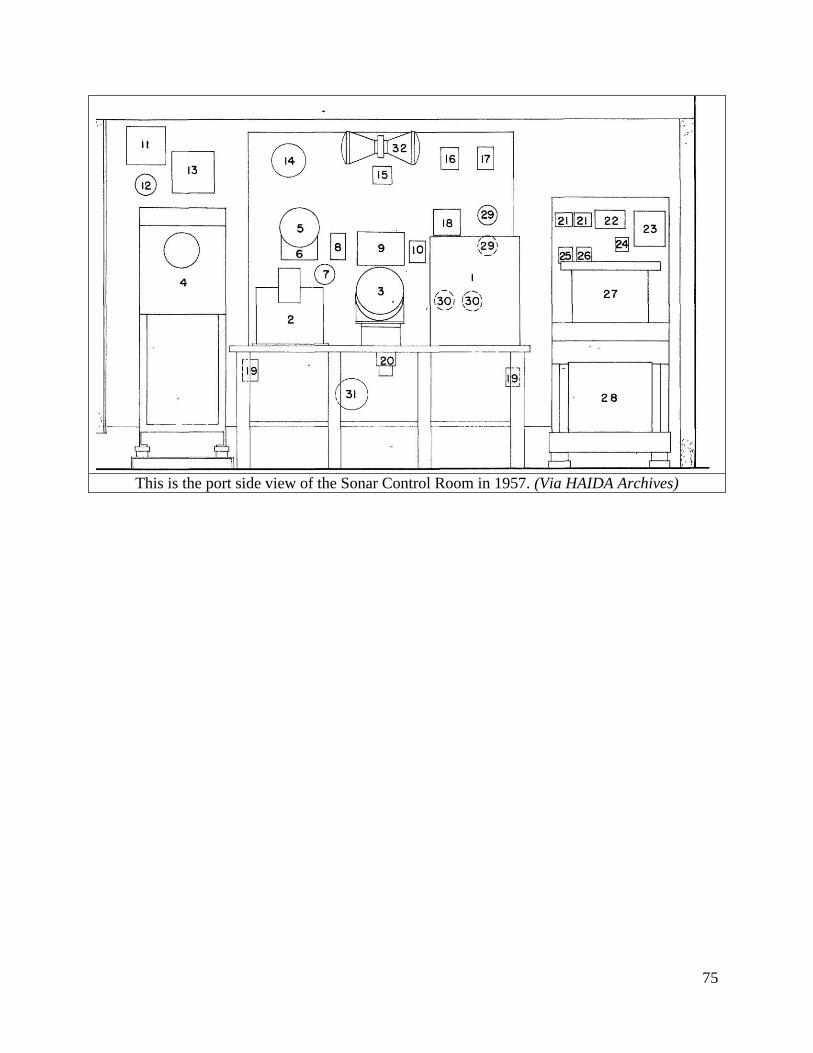
75
This is the port side view of the Sonar Control Room in 1957. (Via HAIDA Archives)

76
This is the equipment listing for the Sonar Control Room for 1957. (Via HAIDA Archives)

77
1963: Equipment ID in this photo:
1) Dome locator. It has three indicator lights: up--moving--down.
2) Gyro repeater.
3) 164B Bearing Recorder. It also sent a signal to readout in the wheel house. When the
bridge gave the order "steer by sonar", the helmsman would follow the sonar bearing
repeater.
4) Operator Position. By turning the knob to a new bearing, the transducer will follow to the
new bearing. By pressing the knob, the sonar set transmits a single pulse.
5) 164B Range Recorder.
6) 164B Down Angle Recorder.
7) Barometer. It does not belong in the SCR and was placed there only to cover up a bunch of
cut cable ends.
Three, small, circular gauges mounted to the plywood bulkhead do not belong there. These
are pressure gauges and were mounted for a movie shoot. They have never been taken down.
The AN/SQS-10 operator's console would have been at the left side of the Sonar Control
Room. HAIDA does not have an example of it. There was also a repeater for it above the
VK5 slave PPI in the Operations Room. .
The AN/SQS-501 recorder is mounted on the starboard bulkhead in the Operations Room.
(Photo by Jerry Proc)

78
5.0 OTHER SOUND BASED SYSTEMS
5.1 Type 761 Depth Recorder
System installed: on build in 1943?
HAIDA paid off with this type.
Haida's equipment manifest from the mid 1940's indicates that a Model 761 echo sounding set
was fitted. To measure water depth, a ship transmits an underwater sound impulse that travels
through the sea at a uniform speed. On reaching the sea bed, an echo is returned which is then
measured and recorded graphically. The interval of the echo is proportional to the depth of the
sea.
761 Echo Sounding Set. (Photo courtesy of the
British Admiralty)

79
5.2 AN/UQC-1B Underwater Telephone
System Installed: ?
HAIDA paid off with this type
This device was an underwater communication set, or as it was more commonly referred to as an
Underwater Telephone. It was designed for use on submarines and surface ships to provide
amplitude modulated (AM) voice or CW communication through the water using a 8.0875 kHz
carrier. AM mode employed Single Side Band (SSB) using the upper side band (USB). The
useable range varied between 8,000 to 12,000 yards depending on ship's speed and sonar
conditions. That is the range quoted for the 'A' and 'B' variants. Morse code used a fixed audio
note of 712 Hz. Personnel stationed on the ship's bridge used a telephone like device when
communicating on voice.
A small, cylindrical, magnetostriction transducer was fitted in the sonar dome, aft of the main
set. A combined receiver-transmitter panel was fitted in the sonar instrument space while the
'sonar set control - remote control unit' (SSC-RCU) was mounted at either the command position
or in the operations room. The SSC- RCU contained a power off/on switch for the set, a
loudspeaker with volume control, a Morse key, a phone/CW switch and a microphone.
A hand written note on one of the source documents for this device indicates that the RCN
ordered 45 sets on the initial procurement. HMCS Haida was fitted with the AN/UQC-1B at the
time she was paid off.
OTHER DATA
Manufacturers: UQC-1, 1A, 1B RCA , Camden N.J.
UQC-1D Bendix Corp, Bendix Pacific Division, North Hollywood California
Production : 1A - March 1958
1B - 1960
1D - 1962
(one Parts Manual for the UQC-1B is dated 1956)
Stock Numbers:
'B' variant - NATO 5845-21-041-1681.
'D' variant - NATO 5845-21-041-5083
Manuals:
Maintenance Standards for AN/UQC-1, 1A, 1B.
Bureau of Ships. NAVSHIPS 91180.42. Contract Number 71851. RCA. March 31, 1958

80
Front view of the receiver-transmitter
cabinet with the service panel removed.
(Graphic courtesy of RCA Victor)
The receiver-transmitter cabinet with both chassis
swung down for servicing. (Graphic courtesy of
RCA Victor)
6.0 OTHER EQUIPMENT
6.1 4356M BOTTLE TRANSMITTER
The bottle transmitter (B.T.) did not emit any radio frequencies. This device was used to provide
transmission to a group of repeater motors, such as those in a radar installation, or to step up the
number of repeaters that can be controlled from a gyro-compass where it is inconvenient to use a
multiple transmitter or transmitter panel. They were also used extensively where it was desired to
use Admiralty type equipment controlled by some other type of gyro compass.
Bottle transmitters fell into two groups -- pattern #5356 that transmitted to M-type repeater
motors and pattern #5355 that transmitted to Sperry-type repeater motors. The B.T. could operate

81
a load equivalent to fifteen Mark 10 M-type repeater motors at its maximum. On HMCS
HAIDA, the bottle transmitter was used to transmit azimuth information from the Admiralty Mk
5 Gyrocompass to remote indicators.
4356M Bottle Transmitter.
(Photo courtesy of the British
Admiralty)
6.2 RTU
HAIDA was fitted with RTU during the mid 1940's. The acronym means Range Transmission
Unit (M type system). It was used to transmit radar information to remote indicators on the ship.
No photo of it is available,
7.0 BIBLIOGRAPHY
To maintain the brevity in this list, extracts in this paper have been made from the respective
equipment manuals whenever those manuals were readily available. Much of the other material
has been extracted from the web page ASDIC, RADAR and IFF SYSTEMS used by the RCN -
WWII and Post War by Jerry Proc. The document can be found at: http://jproc.ca/sari/
Individual Contributors:
1) Peter Huber and Frontline Magazine
2) Sandy McClearn <smcclearn(at)ns.sympatico.ca>
3) Øyvind Garvik <oygarvik(at)online.no>
4) Robert Langille, <ewcs(at)ewcs.ca>5) “ The Threat to the S Band Marine Radar Frequency
Allocation and the Necessity to Preserve It” by John. H. Beattie, Journal of Navigation, no 53

82
(2000), pp 299-312.
6) Extracts from Publication CB 4182/45 Radar Manual (Use of radar) from 1945 provided by
Øyvind Garvik .
7) Øyvind Garvik <oygarvik(at)online.no>
8) Le Musée Québecois de la Radio - Jacques Hamel, VE2DJQ
9) Robert Langille <ewcs(at)ewcs.ca>
8.0 ABOUT THE AUTHOR
Jerry Proc, VE3FAB, a resident of Etobicoke Ontario, has been a licensed amateur radio operator
since 1964 and also holds an Advanced Amateur Radio Operator's Certificate. His interest in
electronics was sparked at a very young age and during the 1960's Jerry developed a fascination
with military radio gear. In 1970, he graduated with a diploma in Electronics Engineering
Technology from the Radio College of Canada. Later, he obtained an Advanced Networking
Certificate through Continuing Education Studies program at Humber College, Etobicoke
Ontario. Jerry has served in both a technical and managerial capacity in the mainframe computer
and data communications field since 1970 and is currently retired from Bell Canada where he
was employed as a network support specialist.
Jerry Proc in August 2015
His involvement with the restoration of radio systems aboard HMCS HAIDA started out quite
innocently in July of 1992. It has now developed into a very engrossing and stimulating
endeavour. In October 1999, his efforts to restore HAIDA's radio rooms and other significant
contributions were recognized by the Historic Naval Ships Association and awarded Jerry the
Bos'n Marvin Curry award, the first Canadian to receive it. In early 2001, Jerry's research work
on radio and radar was officially recognized and incorporated into the Appendices of the book
"HMCS HAIDA - Battle Ensign Flying" by Barry Gough.
To see Jerry's web pages go to URL: http://jproc.ca
9.0 REVISIONS
2015/08/26 - Initial release of manual .
2017/11/01 - Replaced incorrect image of 144Q range recorder with correct image. Added
images of type 164 range and bearing recorders.

83