Revision 13 SB650-03-01
14
Citation SERVICE BULLETIN REVISION Revision 13 SB650-03-01 TRANSMITTAL SHEET This sheet transmits Revision 13 to SB650-03-01. A. Added a note to Step 6E which gives instructions to restore the check valves to production configuration if they were reversed. B. Added airplane -7092 to the serial effectivity. NOTE: This revision replaces the original issue of SB650-03-01 and all previous revisions in their entirety. NOTE: Change bars and pointing hands are not used in this publication to denote revised material. This transmittal sheet provides a complete description of the changes made by this revision, except for editorial changes. REVISION COMPLIANCE NO EFFECT. Airplanes previously modified by this service bulletin are not affected by this revision. SUMMARY OF REVISIONS Original Issue May 18/1984 Revision 1 Jun 8/1984 Revision 2 Jul 19/1985 Revision 3 Jun 3/1987 Revision 4 Apr 1/1993 Revision 5 Jun 17/1993 Revision 6 Mar 17/1995 Revision 7 Jul 31/1995 Revision 8 May 13/1997 Revision 9 Aug 22/1997 Revision 10 Aug 21/2000 Revision 11 Nov 30/2004 Revision 12 Aug 25/2005 Revision 13 Jun 27/2006
Transcript of Revision 13 SB650-03-01

CitationSERVICE BULLETIN
REVISIONRevision 13 SB650-03-01
TRANSMITTAL SHEET
This sheet transmits Revision 13 to SB650-03-01.A. Added a note to Step 6E which gives instructions to restore the check valves to production configuration
if they were reversed.B. Added airplane -7092 to the serial effectivity.
NOTE: This revision replaces the original issue of SB650-03-01 and all previous revisions in their entirety.
NOTE: Change bars and pointing hands are not used in this publication to denote revised material. Thistransmittal sheet provides a complete description of the changes made by this revision, exceptfor editorial changes.
REVISION COMPLIANCE
NO EFFECT. Airplanes previously modified by this service bulletin are not affected by this revision.
SUMMARY OF REVISIONS
Original Issue May 18/1984
Revision 1 Jun 8/1984
Revision 2 Jul 19/1985
Revision 3 Jun 3/1987
Revision 4 Apr 1/1993
Revision 5 Jun 17/1993
Revision 6 Mar 17/1995
Revision 7 Jul 31/1995
Revision 8 May 13/1997
Revision 9 Aug 22/1997
Revision 10 Aug 21/2000
Revision 11 Nov 30/2004
Revision 12 Aug 25/2005
Revision 13 Jun 27/2006

CitationSERVICE BULLETIN
REVISIONRevision 12 SB650-03-01
TRANSMITTAL SHEET
This sheet transmits Revision 12 to SB650-03-01.A. Adds airplane -0080 to the EFFECTIVITY section.
NOTE: This revision replaces the original issue of SB650-03-01 and all previous revisions in their entirety.
NOTE: Change bars and pointing hands are not used in this publication to denote revised material. Thistransmittal sheet provides a complete description of the changes made by this revision, exceptfor editorial changes.
REVISION COMPLIANCE
NO EFFECT. Airplanes previously modified by this service bulletin are not affected by this revision.
SUMMARY OF REVISIONS
Original Issue May 18/1984
Revision 1 Jun 8/1984
Revision 2 Jul 19/1985
Revision 3 Jun 3/1987
Revision 4 Apr 1/1993
Revision 5 Jun 17/1993
Revision 6 Mar 17/1995
Revision 7 Jul 31/1995
Revision 8 May 13/1997
Revision 9 Aug 22/1997
Revision 10 Aug 21/2000
Revision 11 Nov 30/2004
Revision 12 Aug 25/2005


CitationSERVICE BULLETIN
REVISIONRevision 11 SB650-03-01
TRANSMITTAL SHEET
This sheet transmits Revision 11 to SB650-03-01.A. Adds airplane -7067 to the EFFECTIVITY section and Step 4 of the ACCOMPLISHMENT
INSTRUCTIONS.B. Adds Cessna Model 650 Citation VII Wiring Diagram Manual to the REFERENCE section.C. Removes engineering drawings from the MATERIAL INFORMATION section and adds them to the
REFERENCE section.
NOTE: This revision replaces the original issue of SB650-03-01 and all previous revisions in their entirety.
NOTE: Change bars and pointing hands are not used in this publication to denote revised material. Thistransmittal sheet provides a complete description of the changes made by this revision, exceptfor editorial changes.
REVISION COMPLIANCE
NO EFFECT. Airplanes previously modified by this service bulletin are not affected by this revision.
SUMMARY OF REVISIONS
Original Issue May 18/1984
Revision 1 Jun 8/1984
Revision 2 Jul 19/1985
Revision 3 Jun 3/1987
Revision 4 Apr 1/1993
Revision 5 Jun 17/1993
Revision 6 Mar 17/1995
Revision 7 Jul 31/1995
Revision 8 May 13/1997
Revision 9 Aug 22/1997
Revision 10 Aug 21/2000
Revision 11 Nov 30/2004

Citation SERVICE BULLETINSB650-03-01
TITLE
CERTIFICATION REQUIREMENTS - UNITED STATES TO CANADIAN CONVERSION
EFFECTIVITY
MODEL SERIAL NUMBERS
650 -0007, -0014, -0023, -0042, -0062, -0065, -0087, -0101,-0104, -0116, -0195, -7067, -7092
NOTE: This service bulletin may be accomplished only at a Cessna owned Citation Service Center; or, whenindividually approved through Citation Customer Services, at other Cessna authorized service facilities.
NOTE: This service bulletin is not compatible with SB650-27-48.
REASON
To modify an airplane to meet Canadian certification requirements.
DESCRIPTION
This service bulletin provides parts and instructions to install dual hydraulic unloading relief valves,spoiler asymmetry detection system and oil quantity placards, and to modify the spoiler hold-downelectrical system.
COMPLIANCE
OPTIONAL. This service bulletin may be accomplished at the discretion of the owner.
A service bulletin published by Cessna Aircraft Company may be recorded as “completed” in an aircraftlog only when the following requirements are satisfied:
1) The mechanic must complete all of the instructions in the service bulletin, including the intenttherein.
2) The mechanic must correctly use and install all applicable parts supplied with the service bulletinkit. Only with written authorization from Cessna Aircraft Company can substitute parts or rebuiltparts be used to replace new parts.
3) The mechanic or airplane owner must use the technical data in the service bulletin only asapproved and published.
4) The mechanic or airplane owner must apply the information in the service bulletin only to aircraftserial numbers identified in the “Effectivity” section of the bulletin.
5) The mechanic or airplane owner must use maintenance practices that are identified as acceptablestandard practices in the aviation industry and governmental regulations.
No individual or corporate organization other than Cessna Aircraft Company is authorized to make orapply any changes to a Cessna-issued service bulletin, service letter, or flight manual supplement withoutprior written consent from Cessna Aircraft Company.
Cessna Aircraft Company is not responsible for the quality of maintenance performed to comply with thisdocument, unless the maintenance is accomplished at a Cessna-owned Citation Service Center.
May 18/1984 650-03-01Revision 13 - Jun 27/2006 Page 1 of 6
Cessna Aircraft Company, Citation Marketing Division, P.O. Box 7706, Wichita, KS 67277, U.S.A. 1-316-517-6000, Fax 1-316-517-8500
COPYRIGHT © 1984
May 18/1984 650-03-01Revision 13 - Jun 27/2006 Page 2
Citation SERVICE BULLETINSB650-03-01
FLIGHT CREW OPERATIONS
No Change.
APPROVAL
FAA approval has been obtained on technical data in this publication that affects airplane type design.
This information is considered an amendment to the Cessna Manufacturer's Maintenance Manual.
MANPOWER
WORK PHASE MAN-HOURS
Modification *
MATERIAL - Cost and Availability
PART NUMBER AVAILABILITY COST
SB650-03-01-0 * *
SB650-03-01-1 * *
* Refer to the attached Service Bulletin Supplemental Data sheet for man-hours, material cost andavailability, and warranty information.
CONSUMABLE MATERIAL
In addition to the above kit(s), the following materials, or equivalent, are required for the accomplishmentof this service bulletin.
NAME NUMBER MANUFACTURER USE
Adhesive Eastman 910 Eastman Kodak Company343 State StreetRochester, NY 14650
Secure position ofpermaswage fittings intube subassemblies.
Solvent Methyl N-Propyl(MEK)
Commercially available Cleaning.
Solvent Isopropyl Alcohol Commercially available Flush out hydraulic linesbefore installing.
TOOLING
NAME NUMBER MANUFACTURER USE
Permaswage hy-draulic power supply
DLT02MAPP1000 Deutsch Metal Components Division14800 S. Figueroa StreetLos Angeles, CA PO Box 61188
Power supply forpermaswage tool kits.
Permaswage tool, kit#1 (3/16 inch through3/8 inch tubing)
DLT30MAP-SKT3011
Deutsch Metal Components Division14800 S. Figueroa StreetLos Angeles, CA PO Box 61188
Swage tubing.

Citation SERVICE BULLETINSB650-03-01
CHANGE IN WEIGHT AND BALANCE
MODEL 650
WEIGHT INCREASE +6.7 pounds
RESULTANT MOMENT +2101.0 inch-pounds
MOMENT/100 +21.0
REFERENCES
Cessna Model 650 Citation III, VI, and VII Maintenance Manual
Cessna Model 650 Citation III Wiring Diagram Manuals
Cessna Model 650 Citation VII Wiring Diagram Manual
The Cessna Engineering Drawings and documents below are necessary to accomplish this modificationfor all airplanes:
NOTE: The latest revision of each document and all applicable amendments, drawing change notices, andparts lists released at the time of modification must be used.
DRAWING NUMBER DRAWING TITLE
6200011 Canadian DOT Modification Kit - Optional
6218124 Spoiler Asymmetry Box Installation
The Cessna Engineering Drawings and documents below are necessary to accomplish this modificationfor all airplanes:
NOTE: The latest revision of each document and all applicable amendments, drawing change notices, andparts lists released at the time of modification must be used.
DRAWING NUMBER DRAWING TITLE
6217110 Plumbing Installation - Hydraulic Aft Fuselage
6217198 Aft Baggage Bulkhead Installation - Hydraulic
PUBLICATIONS AFFECTED
Cessna Model 650 Citation III, VI, and VII Illustrated Parts Catalog
ACCOMPLISHMENT INSTRUCTIONS
1. (Airplanes 650-0001 thru 650-0104) Install dual unloading relief valves as follows:
A. Remove 9914093-1 Relief Valve from the aft baggage bulkhead hydraulic panel. Cap the fittingswith one each MS21914-6 and MS21914-8 Caps.
B. Install two 70076 Unloading Relief Valves per Cessna Engineering Drawing 6217110. (Refer tothe Maintenance Manual, Chapter 20, Tube Bending Criteria and Permaswaging - MaintenancePractices.)
2. Install the spoiler asymmetry detection system as follows:
A. Install 6218002-5 Spoiler Asymmetry Box in the left side console per Cessna Engineering Drawing6218124.
May 18/1984 650-03-01Revision 13 - Jun 27/2006 Page 3

May 18/1984 650-03-01Revision 13 - Jun 27/2006 Page 4
Citation SERVICE BULLETINSB650-03-01
B. (Airplanes 650-0001 thru 650-0065 not incorporating SB650-27-32.) Replace the 623845-104Spoiler Position Transmitters with the 86784-1 Transmitter. (Refer to the Maintenance Manual,Chapter 27, Speedbrake Position/Indicating System - Maintenance Practices.)
NOTE: The new transmitters may already have been installed as a spares replacement. A newbracket is required to install the new transmitter.
C. Wire the spoiler asymmetry detection system per the Wiring Diagram Manual, Chapter 27, SpoilerAsymmetry Detection.)
3. (Airplanes 650-0001 thru 650-0173.) Modify the spoiler hold-down wiring by performing the 6200011-2Auxiliary Power Junction Box Modification. (Refer to the Wiring Diagram Manual Citation Serial -0001Thru -0173, Chapter 27, Spoiler Asymmetry Detection.)
4. (Airplanes 650-0195 and 650-7067) Install K204 Auxiliary Hydraulic Latch/Spoiler Asymmetry Relayin the left power J-Box. (Refer to the Wiring Diagram Manual Citation Serial -0174 Thru -0199 and-7067,Chapter 27, Speed Brake Asymmetry Detection.)
5. Install 6200181-90 Oil Quantity Placard on the inside of each nacelle oil filler door. Position placards sothey can be read when the filler doors are open.
6. Perform a functional test of the unloading relief valves as follows: NOTE: Test the left and right unloadingrelief valves.
NOTE: A high-flow one gallon-per-minute or more) ground service unit, capable of supplying 4000 psi,must be available for this test. If one is not available, a high pressure hand pump may be used inplace of a ground service unit, but the left and right pressure lines from the engine pumps must becapped. Cap the lines by disconnecting them at a check valve on the aft baggage bulkhead andreversing the check valve.
A. Disconnect the engine-driven hydraulic pump pressure hose from the pump.
B. Connect a ground service unit or hand pump to the pressure hose.
C. Turn on the ground service unit or operate the hand pump and apply 3800 psi to the airplane system.
(1) Check for leaks at all unloading relief valve locations.
(2) Verify that the unloading relief valve does not open at 3800 psi.
D. Increase the hydraulic pressure from the ground service unit or hand pump and verify that theunloading relief valve opens at 4000 psi +100 or -100 psi.
NOTE: Pressure will drop to 200-300 psi if a high-flow ground service unit is used. Pressure willdrop to zero if a hand pump is used.
E. Shut off the ground service unit, disconnect from the airplane, and reconnect the pressure hose tothe engine-driven hydraulic pump.
NOTE: If the check valves were reversed, restore them to production configuration.
7. Bleed the hydraulic system and service the hydraulic reservoir. (Refer to the Maintenance Manual,Chapter 12, Servicing, Hydraulic System Reservoir - Servicing.)
8. Perform the Spoiler/Speedbrake System Operational Test, Auxiliary Hydraulic Pump Electrical ControlFunctional Test and Spoiler Asymmetry Hold-Down Functional Test. (Refer to the Maintenance Manual,Chapter 27, Spoiler/Speedbrake - Adjustment/Test.)
9. Ensure that the latest revision of the FAA Approved on Behalf of Transport Canada Airplane Flight Manualis available for use prior to operation of the airplane.
10. Record that this service bulletin has been completed.
A. Complete a Maintenance Transaction Report.
B. Put a copy of the completed Maintenance Transaction Report in the airplane logbook.
Citation SERVICE BULLETINSB650-03-01
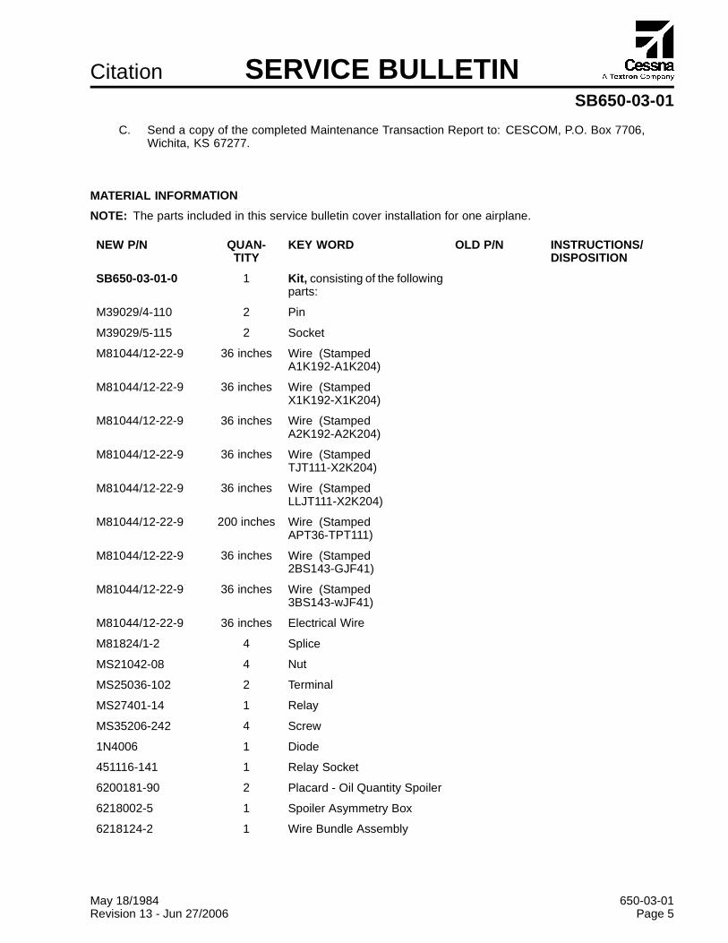
C. Send a copy of the completed Maintenance Transaction Report to: CESCOM, P.O. Box 7706,Wichita, KS 67277.
MATERIAL INFORMATION
NOTE: The parts included in this service bulletin cover installation for one airplane.
NEW P/N QUAN-TITY
KEY WORD OLD P/N INSTRUCTIONS/DISPOSITION
SB650-03-01-0 1 Kit, consisting of the followingparts:
M39029/4-110 2 Pin
M39029/5-115 2 Socket
M81044/12-22-9 36 inches Wire (StampedA1K192-A1K204)
M81044/12-22-9 36 inches Wire (StampedX1K192-X1K204)
M81044/12-22-9 36 inches Wire (StampedA2K192-A2K204)
M81044/12-22-9 36 inches Wire (StampedTJT111-X2K204)
M81044/12-22-9 36 inches Wire (StampedLLJT111-X2K204)
M81044/12-22-9 200 inches Wire (StampedAPT36-TPT111)
M81044/12-22-9 36 inches Wire (Stamped2BS143-GJF41)
M81044/12-22-9 36 inches Wire (Stamped3BS143-wJF41)
M81044/12-22-9 36 inches Electrical Wire
M81824/1-2 4 Splice
MS21042-08 4 Nut
MS25036-102 2 Terminal
MS27401-14 1 Relay
MS35206-242 4 Screw
1N4006 1 Diode
451116-141 1 Relay Socket
6200181-90 2 Placard - Oil Quantity Spoiler
6218002-5 1 Spoiler Asymmetry Box
6218124-2 1 Wire Bundle Assembly
May 18/1984 650-03-01Revision 13 - Jun 27/2006 Page 5

May 18/1984 650-03-01Revision 13 - Jun 27/2006 Page 6
Citation SERVICE BULLETINSB650-03-01
NEW P/N QUAN-TITY
KEY WORD OLD P/N INSTRUCTIONS/DISPOSITION
6218124-3 1 Wire Bundle Assembly
SB650-03-01 1 Instructions
Airplanes -0001 thru -0104, order the following kit in addition to the SB650-03-01 kit.
NEW P/N QUAN-TITY
KEY WORD OLD P/N INSTRUCTIONS/DISPOSITION
SB650-03-01-1 1 Kit, consisting of the followingparts:
AN894D10-8 2 Reducer
AN6289-8 2 Nut
S2909J08 4 Sleeve
S2910-08 4 Nut
S2917D10 2 Tee
MS21902D10 2 Union
MS21909-8 2 Tee
MS21914-6 1 Cap
MS21914-8 1 Cap
MS28773-08 2 Retainer
MS28778-8 4 O-Ring
MS28778-10 2 O-Ring
70076 2 Valve, Unloading Relief
6207023-43 1 Line Assembly, Left
6207023-48 1 Line Assembly, Right
6207023-3 1 Line Assembly
6217198-3 1 Bulkhead Installation

CitationSERVICE BULLETIN
SUPPLEMENTAL DATASB650-03-01
TITLE
CERTIFICATION REQUIREMENTS - UNITED STATES TO CANADIAN CONVERSION
EFFECTIVITY
MODEL SERIAL NUMBERS
650 -0007, -0014, -0023, -0042, -0062, -0065, -0087, -0101,-0104, -0116, -0195, -7067, -7092
MANPOWER
WORK PHASE MAN-HOURS
Modification *
MATERIAL - Cost and Availability
PART NUMBER AVAILABILITY COST
SB650-03-01-0 * *
SB650-03-01-1 * *
* Please contact Citation Parts Distribution for current cost and availability of parts listed in this servicebulletin. Phone at 1-800-835-4000 (Domestic) or 1-316-517-7542 (International). Send Email to:[email protected] or telefax at 1-316-517-7711.
Based on availability and lead times, parts may require advanced scheduling.
In cases where the required part(s) are available as exchange, order the exchange part and, uponcompletion, expedite the return of the removed core to avoid return penalties. Contact the Citation PartsDistribution Sales Desk for availability of exchange parts.
May 18/1984 650-03-01Revision L - Jun 27/2006 Page 1 of 1
Cessna Aircraft Company, Citation Marketing Division, P.O. Box 7706, Wichita, KS 67277, U.S.A. 1-316-517-6000, Fax 1-316-517-8500
COPYRIGHT © 1984


![NEI 03-01 [Revision 2] · 2012-12-01 · NEI 03-01 (Revision 2) Draft September 2008 ACKNOWLEDGEMENTS This document, NEI 03-01, Nuclear Power Plant Access Authorization Program, was](https://static.fdocuments.us/doc/165x107/5e88e8ab72cf501305111bda/nei-03-01-revision-2-2012-12-01-nei-03-01-revision-2-draft-september-2008.jpg)