REVISED GEOTECHNICAL ENGINEERING … Group is pleased to submit this revised geotechnical...
43
REVISED GEOTECHNICAL ENGINEERING REPORT ROUTE 608 WIDENING TINKLING SPRING ROAD AUGUSTA COUNTY, VIRGINIA JOB NUMBER: 34049.002 PREPARED FOR: AUGUSTA COUNTY DEPARTMENT OF COMMUNITY DEVELOPMENT P.O. BOX 590 VERONA, VIRGINIA 24482 March 8, 2016 Revised July 23, 2016
Transcript of REVISED GEOTECHNICAL ENGINEERING … Group is pleased to submit this revised geotechnical...

REVISED GEOTECHNICAL ENGINEERING REPORT
ROUTE 608 WIDENING TINKLING SPRING ROAD
AUGUSTA COUNTY, VIRGINIA
JOB NUMBER: 34049.002
PREPARED FOR:
AUGUSTA COUNTY DEPARTMENT OF COMMUNITY DEVELOPMENT
P.O. BOX 590 VERONA, VIRGINIA 24482
March 8, 2016
Revised July 23, 2016

TABLE OF CONTENTS EXECUTIVE SUMMARY ............................................................................................. A
1. PROJECT INFORMATION .................................................................................... 1 2. FIELD EXPLORATION .......................................................................................... 2 3. LABORATORY TESTING ...................................................................................... 3 4. SITE GEOLOGY ....................................................................................................... 4 5. SUBSURFACE CONDITIONS ................................................................................ 5
5.1 Ground Surface Cover ........................................................................................ 5 5.2 Existing Fill Soils ................................................................................................ 5 5.3 Residual Soils...................................................................................................... 5 5.4 Groundwater ....................................................................................................... 5
6. EXISTING PAVEMENT SECTION THICKNESSES .......................................... 5 7. CONCLUSIONS AND RECOMMENDATIONS .................................................. 6
7.1 Site Preparation ................................................................................................... 6 7.1.1 General .................................................................................................... 6 7.1.2 Subgrade Evaluation ............................................................................... 7
7.2 Excavations ......................................................................................................... 7 7.3 Embankment Fill ................................................................................................. 8
7.3.1 Embankment Fill Materials..................................................................... 8 7.3.2 Re-use of On-Site Soils as Embankment Fill ......................................... 8 7.3.3 Compaction Recommendations .............................................................. 8
7.4 Embankment Fill Slopes ..................................................................................... 8 7.5 Anticipated Foundation Materials ....................................................................... 8 7.6 Pavement Support ............................................................................................... 8
7.6.1 Proposed Lane Widening ........................................................................ 9 7.6.2 Existing Route 608 Pavement Section .................................................. 10
8. LIMITATIONS OF REPORT ................................................................................ 10 9. CLOSURE ................................................................................................................ 11
APPENDICES
Appendix A – Figures Appendix B – Boring Logs Appendix C – Laboratory Test Results Appendix D – Pavement Calculations Appendix E – Asphalt Core Photo Logs

A
EXECUTIVE SUMMARY
For your convenience, this report is summarized in outline form below. This brief summary should not be used for design or construction purposes without reviewing the more detailed conclusions and recommendations contained in this report.
1. The field exploration included a visual site reconnaissance by a representative of Timmons Group and the performance of seven hand auger borings (HA-01, HA-02, HA-02A, HA-03, HA-04, HA-04A and HA-05) and five pavement cores (C-01 through C-05).
2. The borings encountered approximately one inch of surficial topsoil. Existing fill soils were encountered in all the hand auger borings, except for HA-02 and HA-02A, to depths up to five feet below the ground surface. The fill consisted of soft to very stiff elastic silt (MH), lean clay (CL), silt (ML) and very loose to medium dense silty sand (SM). Beneath the topsoil and fill, undisturbed residual soils were encountered in hand auger borings HA-01, HA-02 HA-02A and HA-03 up to depths up to 3.5 feet below the ground surface. The soils consisted of medium dense silty sand (SM). At the time of exploration, water was not encountered in the borings.
3. We recommend that site grading be conducted during the typically drier summer months.
4. Near-surface soils typically appeared relatively stiff. However, existing fill in one of the hand auger borings (HA-05) appeared soft to a depth of about 2 to 3 feet. The near-surface soils in the vicinity of boring HA-05 are anticipated to be below the density required by VDOT Road and Bridge Specifications and are anticipated to require additional densification or repairs.
5. Rock materials are expected to be encountered at depths of approximately 4 feet from existing grade.
6. We recommend new pavement sections consist of 7 inches of asphalt pavement underlain by 8 inches of VDOT 21B stone and a VDOT approved stabilization geotextile. This report provides the required strength parameters for the stabilization geotextile.
7. Our evaluation indicates that existing Route 608 pavement sections combined with planned asphalt pavement build-up should be sufficient to support design traffic loading.

1
1001 Boulders Parkway Suite 300 Richmond, VA 23225
P 804.200.6500 F 804.560.1016 www.timmons.com
July 23, 2016
Augusta County Department of Community Development Post Office Box 590 Verona, Virginia 24482
Attention: Mr. Jerry Van Lear
Re: Revised Geotechnical Engineering Report Route 608 Widening Tinkling Spring Road (Route 608) Augusta County, Virginia Timmons Group Project No. 34049.002 Mr. Van Lear:
Timmons Group is pleased to submit this revised geotechnical engineering report for the referenced project. This report is a second revision to our original Geotechnical Engineering Report dated March 8, 2016. Revisions were made to address recent VDOT comments on the original report and first revision. The objectives of our services were to explore subsurface conditions and provide our geotechnical recommendations for site grading and pavement support.
1. PROJECT INFORMATION
The project corridor is located along Route 608 (Tinkling Spring Road) in Augusta County, Virginia. A Site Vicinity Map is shown on Figure 1. Proposed construction will consist of upgrading Route 608 from two to four lanes through the construction of two new southbound lanes. In addition, the existing Route 608 will receive pavement build-up and overlays to improve the existing pavement section. A new median will also be constructed. The project corridor is approximately 2,400 feet long and will extend from Ramsey Road to approximately 600 feet west of Ladd Road.
Currently, the site consists of an asphalt roadway with two lane directional travel lanes and center turn lane. The site is bounded by open fields to the north, commercial property to the south, Ramsey Road to the west and Ladd Road to the east. The ground surface in the proposed roadway area is currently relatively flat.

Geotechnical Engineering Report Project No.34049.002 Route 608 Widening – Augusta County, VA July 23, 2016
2
We have reviewed a Geotechnical Data Report (dated July 14, 2011, UPC No. 75877) by the Virginia Department of Transportation (VDOT), Staunton District Materials Section for the I-64 Exit 91 Interchange and Bridge Improvements at Route 285, Augusta County, Virginia. This project is located just east of the site referenced in this report. We have also reviewed a Final Soil Survey and Minor Structure Report dated July 13, 2012 by VDOT (UPC No. 97029) for a left turn lane on Route 608 at Route 635. This latter project is located just west of the site referenced in this report.
2. FIELD EXPLORATION
The field exploration included a visual site reconnaissance by a representative of Timmons Group and the performance of seven hand auger borings (HA-01, HA-02, HA-02A, HA-03, HA-04, HA-04A and HA-05) and five pavement cores (C-01 through C-05). Core and hand auger boring locations were selected by Timmons Group. A representative of Timmons Group established locations in the field using GPS equipment. Approximate boring locations are shown on Figure 2 in the Appendix.
Hand auger borings were performed to depths ranging from about 0.5 to 5 feet below the ground surface. Several of the hand auger borings encountered shallow refusal due to the presence of very stiff soils. Encountered materials were visually classified in the field. The DCP test procedure is as follows: The cone point of the penetrometer is first seated 2 inches into the bearing materials to embed the point. Then the cone point is driven an additional 1-3/4 inches using a 15-pound weight falling 20 inches. The penetrometer reading is the number of blows required to drive the cone point 1-3/4 inches. The cone point is then driven a second and third increment of 1-3/4 inches each and the penetrometer readings are recorded. The “average” penetration reading is the average of the second and third penetration readings. The penetrometer reading is similar to the standard penetration resistance “N-value” as defined by ASTM D 1586. The penetrometer test results provide an index for estimating soil strength and relative density.
Pavement cores were performed with a 4-inch diameter diamond-impregnated core barrel. Following coring operations, underlying crushed stone was excavated with a hand auger. Pavement and crushed stone thicknesses were then recorded. The core holes were backfilled with excavated crushed stone and the surface was patched with compacted asphalt.
Water levels were measured in open boreholes at the time of drilling. Upon completion, boreholes were then backfilled up to the original ground surface with auger cuttings. Representative portions of soil samples and the bulk samples were returned to our laboratory for quantitative testing and visual classification in general accordance with Unified Soil Classification System guidelines.
Hand auger boring logs are provided in the Appendix. Although the logs show distinct boundaries in soils types, changes in soil types are often gradual and cannot be defined at particular depths.

Geotechnical Engineering Report Project No.34049.002 Route 608 Widening – Augusta County, VA July 23, 2016
3
Ground surface elevations shown on the logs were interpolated from the topographic plan for this project and should be considered approximate.
3. LABORATORY TESTING
Laboratory testing was performed on representative split-spoon and bulk soil samples obtained from the borings. This testing consisted of natural moisture content, Atterberg limits, grain size analyses, standard Proctor, California Bearing Ratio (CBR), pH, and resistivity tests. Laboratory tests were performed in general accordance with applicable ASTM procedures. Individual laboratory test data sheets are provided in the Appendix. A summary of laboratory test data is provided in the tables below.
Natural Moisture and Classification Tests
Boring Sample Depth (Feet)
Natural Moisture Content
(%)
Atterberg Limits
Grain Size Analysis USCS
Classification LL PL PI
% Sand
% Fines*
HA-01 S-2 1-2 31.2 54 39 15 47.5 37.7 SM HA-02A Bulk 0-1.5 16.5 44 29 15 40.4 29.0 SM HA-03 S-2 1-2 38.0 72 35 37 15.1 78.2 MH HA-04 Bulk 0-1 34.0 60 33 27 28.7 43.0 SM HA-05 S-3 2-3 30.4 59 34 25 24.0 63.3 MH
*Material passing No. 200 sieve (clay and silt)
Standard Proctor and CBR Testing
Boring Depth (Feet)
Natural Moisture Content
(%)
Standard Proctor
CBR (0.1”)
%Swell USCS
Classification
Optimum Moisture Content
(%)
Maximum Dry
Density (pcf)
HA-02A 0-1.5 16.5 13.1 116.6 6.2 2.4 SM HA-04 0-1 30.4 16.8 107.3 3.1 4.1 SM
Based on the Atterberg limits testing, near-surface soils are of low to high plasticity. Based on comparison of natural moisture contents to the optimum moisture contents of the bulk samples, near-surface soils appear wet of optimum moisture. Drying of some near-surface soils will be required prior to their re-use as embankment fill. The time of year the grading occurs will likely have a significant impact on the moisture levels of near-surface soils.
Geotechnical Engineering Report Project No.34049.002 Route 608 Widening – Augusta County, VA July 23, 2016
4
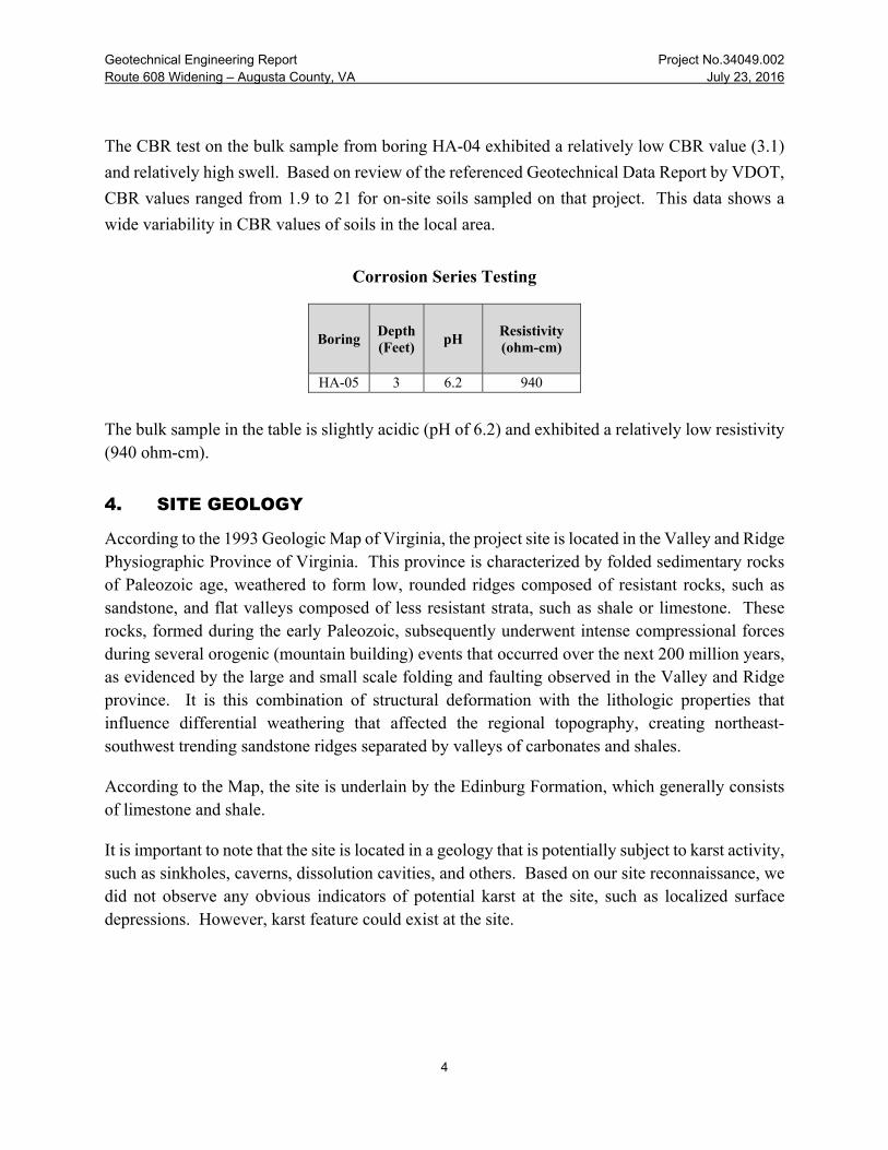
The CBR test on the bulk sample from boring HA-04 exhibited a relatively low CBR value (3.1)
and relatively high swell. Based on review of the referenced Geotechnical Data Report by VDOT,
CBR values ranged from 1.9 to 21 for on-site soils sampled on that project. This data shows a
wide variability in CBR values of soils in the local area.
Corrosion Series Testing
Boring Depth (Feet)
pH Resistivity (ohm-cm)
HA-05 3 6.2 940
The bulk sample in the table is slightly acidic (pH of 6.2) and exhibited a relatively low resistivity (940 ohm-cm).
4. SITE GEOLOGY
According to the 1993 Geologic Map of Virginia, the project site is located in the Valley and Ridge Physiographic Province of Virginia. This province is characterized by folded sedimentary rocks of Paleozoic age, weathered to form low, rounded ridges composed of resistant rocks, such as sandstone, and flat valleys composed of less resistant strata, such as shale or limestone. These rocks, formed during the early Paleozoic, subsequently underwent intense compressional forces during several orogenic (mountain building) events that occurred over the next 200 million years, as evidenced by the large and small scale folding and faulting observed in the Valley and Ridge province. It is this combination of structural deformation with the lithologic properties that influence differential weathering that affected the regional topography, creating northeast-southwest trending sandstone ridges separated by valleys of carbonates and shales.
According to the Map, the site is underlain by the Edinburg Formation, which generally consists of limestone and shale.
It is important to note that the site is located in a geology that is potentially subject to karst activity, such as sinkholes, caverns, dissolution cavities, and others. Based on our site reconnaissance, we did not observe any obvious indicators of potential karst at the site, such as localized surface depressions. However, karst feature could exist at the site.

Geotechnical Engineering Report Project No.34049.002 Route 608 Widening – Augusta County, VA July 23, 2016
5
5. SUBSURFACE CONDITIONS
The following is a summary of subsurface conditions encountered during our exploration.
5.1 Ground Surface Cover
The borings encountered approximately one inch of surficial topsoil.
5.2 Existing Fill Soils
Existing fill soils were encountered in all the hand auger borings, except for HA-02 and HA-02A, up to five feet below the ground surface. The fill consisted of very loose to medium dense silty sand (SM), soft to very stiff lean clay, elastic silt (MH), silt (ML). The predominant near-surface soil type encountered in the borings was silty sand. Average Dynamic Cone Penetrometer (DCP) values in these soils were 3 to greater than 25 blows per increment.
5.3 Residual Soils
Beneath the topsoil and fill, undisturbed residual soils were encountered in hand auger borings HA-01, HA-02 HA-02A and HA-03 up to depths up to 3.5 feet below the ground surface. The soils consisted of medium dense silty sand (SM). Average Dynamic Cone Penetrometer (DCP) values in these soils were 25+ blows per increment.
5.4 Groundwater
At the time of exploration, water was not encountered in the hand auger borings. It is important to realize that groundwater levels will fluctuate with changes in rainfall and evaporation rates. In addition, perched groundwater could be encountered within near-surface soils, particularly after rainfall.
6. EXISTING PAVEMENT SECTION THICKNESSES
Pavement cores were performed along Tinkling Spring Road (Route 608) to measure existing asphalt pavement and underlying crushed stone thicknesses. Cores were conducted in October 2015. A summary of the encountered pavement and crushed stone (stone base) thicknesses are summarized in the table below.

Geotechnical Engineering Report Project No.34049.002 Route 608 Widening – Augusta County, VA July 23, 2016
6
Measured Pavement Section Thicknesses
Core Asphalt
Thickness (inches)
Stone Base
(inches) C-01 7.5 4.5 C-02 7 5.75* C-03 5.5 1.75* C-04 6 3* C-05 7.25 1.5*
*Hand auger refusal in stone base material
Asphalt core photo logs are provided in Appendix E. It is important to note that location of core C-05 had just received an approximately 2-inch mill and overlay from an adjacent construction project. In addition, the location of core C-01 has received a mill and overlay associated with a different construction project since the time of our coring.
7. CONCLUSIONS AND RECOMMENDATIONS
The following conclusions and recommendations are based upon our hand auger borings, laboratory testing, engineering analysis, and past experience with similar projects and subsurface conditions
When reviewing our recommendations, it is important to note the prior development activities have occurred at this site. Based on our past experience with previously developed sites, unexpected subsurface conditions are often encountered. These conditions could include additional zones of low-consistency fill, debris-laden materials, abandoned utilities, and others. These conditions, if encountered, can be addressed by on-site engineering evaluation at the time of construction.
7.1 Site Preparation
7.1.1 General
Site grading will be difficult during periods of extended rainfall and low temperatures that generally occur during the winter months. If grading is conducted during a wet time period, soils will tend to rut and pump under rubber-tired traffic and provide poor subgrade support for pavements. Heavy rubber-tired construction equipment should not be allowed to operate on wet or unstable subgrades at this site due to the potential for rutting and other damage to the soils. To reduce potential earthwork problems, site preparation and grading should be scheduled during the

Geotechnical Engineering Report Project No.34049.002 Route 608 Widening – Augusta County, VA July 23, 2016
7
typically drier summer months, if possible. We recommend that exposed subgrades be sloped and sealed at the end of each day to promote runoff and reduce infiltration from rainfall.
Site preparation should begin with stripping of topsoil, removal of existing pavements (where required per project plans) and removal of any other unsuitable materials. Approximately one inch of topsoil was encountered in the borings. However, stripping activities often mix topsoil with underlying “clean” soils and cause stripping depths to be greater than actual topsoil depths, particularly during wet periods of the year. Topsoil should be wasted from the site or permanently stockpiled outside the proposed construction limits.
7.1.2 Subgrade Evaluation
After stripping of topsoil, soil subgrades to receive embankment fill, and finished subgrades, should be prepared in accordance with the latest edition of the VDOT Road and Bridge Specifications. We recommend the proofrolling of these subgrades be performed as a supplemental tool to help identify subgrade materials that are not compacted to sufficient density (per the above VDOT Specifications). We recommend that proofrolling be performed with a loaded tandem axle dump truck or equivalent.
Based on the borings, near-surface soils were relatively stiff in borings HA-01 through HA-04. However, approximately 2 to 3 feet of relatively soft existing fill was encountered in boring HA-05 and are not expected to meet VDOT density requirements. We expect that additional densification or repair of near-surface soils will be required in the vicinity of boring HA-05.
USCS soil types MH and CH are considered to be unsuitable soils on this project. Some highly plastic soils (MH) were encountered in the borings, but they were not encountered at the anticipated pavement subgrade elevation. Sites grades are currently at grade or will receive fill to reach finished grades. It is possible that these unsuitable soils could exist at finished subgrade between the boring locations. Where these unsuitable soils are encountered at finished subgrade, they should be removed to a depth of 2 feet and replaced with suitable, well-compacted materials.
7.2 Excavations
We expect that excavations will typically extend through moderate consistency soils. Based on referenced VDOT studies (UPC No. 75877 and UPC No. 97029), rock materials may be encountered within 4 feet of the ground surface.
Soil types with respect to trench safety must be evaluated on a case-by-case basis. The Contractor should be responsible for all site safety, including the determination of appropriate trench safety measures according to OSHA guidelines.

Geotechnical Engineering Report Project No.34049.002 Route 608 Widening – Augusta County, VA July 23, 2016
8
7.3 Embankment Fill
7.3.1 Embankment Fill Materials
Embankment fill should contain less than 5 percent organics or debris, have a maximum particle size of 3 inches, have a maximum liquid limit (LL) of 50, and have a maximum plasticity index (PI) of 30. Embankment fill must meet or exceed a CBR of 5.0 (VDOT Test Method VTM 8).
7.3.2 Re-use of On-Site Soils as Embankment Fill
Based on visual observation and comparison of the measured natural moisture contents of the bulk soil samples to the optimum moisture contents from the standard Proctor tests, near-surface soils appeared wet of optimum moisture. Prevailing weather conditions will have a significant impact on the amount of moisture manipulation (i.e., drying or wetting) required prior to embankment fill placement. However, based on our exploration, drying of some on-site soils should be anticipated prior to embankment fill placement.
7.3.3 Compaction Recommendations
Embankment fill should be compacted in accordance with the latest addition of the VDOT Road and Bridge Specifications. Embankment fill testing should be performed in accordance with the procedures and sampling frequencies in Section 309 of the VDOT Manual of Instruction, Chapter III.
7.4 Embankment Fill Slopes
Embankment fill slopes with heights of 6 feet or less will be required on this project. We recommend these slopes be constructed at inclinations of 3(H):1(V) and in accordance with the fill placement recommendations of this report.
7.5 Anticipated Foundation Materials
We have performed a review of the referenced VDOT geotechnical reports (UPC No. 75877 and UPC No. 97029) adjacent to the subject project. Based on our exploration and these referenced VDOT reports, storm sewer pipes and associated structures installed between the existing ground surface and to a depth of 4 feet below existing ground are assumed to have a soil foundation. Structures installed below a depth of 4 feet are assumed to have a rock foundation.
7.6 Pavement Support
Analyses (using AASHTO 1993 method and VDOT Manual of Instruction VI) were performed to calculate the required thickness for proposed lane widening of Route 608 (Tinkling Spring Road). In addition, we evaluated the structural adequacy of existing Route 608 pavement sections

Geotechnical Engineering Report Project No.34049.002 Route 608 Widening – Augusta County, VA July 23, 2016
9
(including planned pavement build-up) to support future traffic. The combined existing pavement and build-up sections were compared to the pavement structural number required for proposed lane widening. These analyses are discussed below, and calculations are presented in Appendix D. All materials and construction methods should conform to the latest edition of the VDOT Road and Bridge Specifications.
7.6.1 Proposed Lane Widening
Annual daily traffic (ADT) for 2014 and 2034 were provided. An average growth rate was determined based on the difference between the ADT values. A design CBR value of 3.1 was use in the analysis (i.e., two-thirds of the average measured laboratory CBR values). A summary of parameters used for the pavement design and the recommended section for new pavements are present below.
New Route 608 Pavement Design Criteria - A design life of 20 years, 2014 ADT of 12,000, growth rate of 2.4 percent, 3% daily truck traffic with average ESAL factor of 1.05, CBR value of 3.1 percent, terminal serviceability = 2.8, reliability = 90%, initial serviceability = 4.2, standard deviation = 0.49 for flexible (asphalt) pavements.
Based on our analysis, the recommended section for new pavements is 7 inches of asphalt pavement over 8 inches of VDOT 21B stone that is underlain by a VDOT approved stabilization geotextile fabric, with the specifications listed below. The recommended pavement section is presented in the table below. Pavement calculations are provided in the Appendix D.
Recommended Section for New Pavements
Route 608 (Tinkling Spring Road)
VDOT SM-12.5D at 220 lb/square yard
2 Inches VDOT IM 19.0A
3 Inches VDOT BM-25.0A
8 Inches VDOT 21B
VDOT Approved Stabilization Geotextile (See required strength properties below)
Geotechnical Engineering Report Project No.34049.002 Route 608 Widening – Augusta County, VA July 23, 2016
10
The VDOT approved stabilization geotextile should meet or exceed the following strength properties:
Ultimate tensile strength (ASTM D4595) – 2,500 lb/ft Tensile strength at 2% strain (ASTM D4595) – 500 lb/ft Tensile strength at 5% strain (ASTM D4595) – 1,200 lb/ft
7.6.2 Existing Route 608 Pavement Section
To evaluate the structural adequacy of the existing Route 608 pavement section (including planned build-up with new asphalt pavement), we assigned structural coefficients to existing and new pavement and then compared the structural number of the proposed pavement section to the required structural number. A required structural number of 4.53 was calculated based on the analysis described in the previous section.
The pavement sections at core locations C-1 and C-5 received a recent mill and overlay. The pavement near core C-1 received the mill and overlay after our coring operations. Because the core thicknesses at these two locations resulted in at least 7 inches of asphalt and the pavement has a new surface wearing course, it is our opinion that existing pavement sections at these core locations are sufficient to support the design traffic loads.
Core locations C-2 through C-4 have not received a recent mill and overlay. The planned asphalt pavement build-up at these three core locations ranges from 3 to 12 inches. Our calculations, which are presented in Appendix D, show that proposed pavement sections (including build-up) at locations C-02 through C-04 will be structurally adequate to support design traffic loads.
Accounting for recent overlay operations (from adjacent projects), for all existing pavements between Stations 312+50 and 324+00 that are to remain in place, we recommend that the existing pavement surface be milled to a depth of 2 inches prior to build-up or overlain with new pavements.
8. LIMITATIONS OF REPORT
The recommendations contained in this report are made on the basis of the site information made available to us and the surface and subsurface conditions that existed at the time of the exploration. While this exploration has been conducted in accordance with generally accepted geotechnical engineering practices, there remains some potential for variation of the subsurface conditions in unexplored areas of the site. If the subsurface conditions encountered during construction vary significantly from those presented in this report, we should be notified to reevaluate our recommendations. No other warranty, expressed or implied, is made as to the professional advice included in this report.

Geotechnical Engineering ReportRoute 608 Wideninq - Auqusta Countv, VA
Project No.34049.002Julv 23,2A16
conditions in unexplored areas of the site. If the subsurface conditions encountered during
construction vary significantly from those presented in this report, we should be notified toreevaluate our recouunendations. No other warranty, expressed or implied, is made as to theprofessional advice included in this report.
9. GLOSURE
:We appreciate this opportunity to be of service to you on this project. If you have any questions
regarding this study or if we can be of further assistance, please contact us at (804) 200-6500.
'Respectfully submitted,Trmuoxs Gnoup
JulianM. Ruffin IV, P.E.
Seotechnical Engineer: Nathan Reeves, P.E.
technical EngineerVA Registration No. 049619
H iE7,rHSrN^n{AhrRE;*A
No.049619 ^g
furo**-$
11

APPENDIX A
FIGURES

FIGURE
1SITE VICINITY MAP
ROUTE 608 WIDENINGAUGUSTA COUNTY, VA
SCALE:
PLOTTED BY:
DATE:
NTS
CHECKED BY: JNR
JMR
10-8-2015 PROJECT NUMBER: 34049.002
Source: Google Maps
NORTH
APPROXIMATE SITE LOCATION

W
W
W
U
G
T
U
G
T
U
G
T
S
5
O
H
P
O
H
P
O
H
P
O
H
P
O
H
P
XX
XX
3
1
5
HA-04
HA-05
C-01
C-02
C-03
C-05
A
N
G
E
L
A
R
O
A
D
P
C
P
C
C
3
0
9
3
1
0
3
1
1
3
1
2
3
1
3
3
1
4
3
1
6
3
1
7
3
1
8
3
1
9
3
2
0
3
2
1
3
2
2
3
2
3
3
2
4
3
2
5
3
2
6
3
2
7
3
2
8
3
2
9
3
3
0
C-04
HA-01
HA-02
HA-03
R
O
U
T
E
6
0
8
IV
Y
R
ID
G
E
L
A
N
E
11BH-003
JO
B N
O.
SH
EET N
O.
SCALE
DESIG
NED
BY
CH
ECKED
BY
DATE
DRAW
N BY
DATE
REVISION DESCRIPTION
These plans and associated documents are the exclusive property of TIMMONS GROUP and may not be reproduced in whole or in part and shall not be used for any purpose whatsoever, inclusive, but not
limited to construction, bidding, and/or construction staking without the express written consent of TIMMONS GROUP.
10/8/2015
ROUTE 608 WIDENING
AUGUSTA COUNTY - VIRGINIA
34049.002
2
LOCATION PLAN
J. RU
FFIN
N. REEVES
N. REEVES
K:\Geotechnical\PROJECTS\2015 Projects\34049.002 August Co - Route 608\Drafting\Boring Location Plan.dwg | Plotted on 3/3/2016 9:26 AM | by Julian Ruffin
.
.
AS SH
OW
N
0
SCALE 1"=200'
400'200'
APPROXIMATE LOCATION OF HAND AUGER BORING
NAD 83
APPROXIMATE LOCATION OF ASPHALT CORE
APPROXIMATE LOCATION OF TEST BORING VDOT
PROJECT NO. 0064-007-111 (JULY 14, 2011)

APPENDIX B
BORING LOGS

Project: Route 608Project No:Performed By: Matthew Thornton
Depth (Feet)
1 2 3 Average
10/15/2015 HA-01 0 to 1FILL consisting of orange-brown, lean clay with sand, trace gravel, moist (FL)
0 16 25+ --- 20+
1 to 2 FILL consisting of Fine to coarse, silty SAND, with gravel, moist (FL) 1 25+ --- --- 25+
2 to 3 Orange-brown, fine to coarse, silty SAND, with gravel, moist (SM) 2 25+ --- --- 25+
3 to 3.5 Orange-brown, sandy SILT, moist (ML) 3 25+ --- --- 25+
3.5 No recovery; Hand Auger Refusal 3.5 25+ --- --- 25+
Boring terminated at 3.5 feetNo water encountered in boring
Exploration located on active construction site10/15/2015 HA-02 0 to 0.1 Topsoil approximately 1" 0 25+ --- --- 25+
0.1 to 0.5 Orange-brown, fine to coarse, silty SAND with gravel, moist (SM) 0.5 25+ --- --- 25+
0.5 No recovery; Hand Auger Refusal
Boring terminated at 0.5 feetNo water encountered in boring
Offset 9' North10/15/2015 HA-02A 0 to 0.1 Topsoil approximately 1" 0 8 10 10 9
0.1 to 1.5 Orange-brown, fine to coarse, silty SAND with gravel, moist (SM) 1 20 25+ --- 22+
1.5 No recovery; Hand Auger Refusal 1.5 25+ --- --- 25+
Boring terminated at 1.5 feetNo water encountered in boring
Auger cuttings collected as bulk material from a depth of 0 to 1.5'
The dynamic cone penetrometer (DCP) test procedure is as follows: The cone point of the penetrometer is first seated 2 inches into the undisturbed bottom of borehole to embed the point. Then the cone point is driven three consecutive 1-3/4 inch depth intervalsusing a 15-pound weight falling 20 inches. The penetrometer reading is the number of blows required to drive the cone point 1-3/4 inches. An average is taken from the three readings.
Reference: "Dynamic Cone for Shallow In‐Situ Pentration Testing," Sowers and Hedges, 1966.
HAND AUGER BORING LOG
Date BoringDepth (Feet)
Description
DCP Values
34049.002

Project: Route 608Project No:Performed By: Matthew Thornton
Depth (Feet)
1 2 3 Average
10/15/2015 HA-03 0 to 0.1 Topsoil approximately 1" 0 12 17 15 14
0.1 to 1FILL consisting of orange-brown, fine to coarse, silty SAND with gravel, moist (FL)
1 5 5 5 5
1 to 2FILL consisting of red-brown, Elastic SILT with sand, trace gravel, moist (FL)
2 16 25 25+ 22+
2 to 2.6 Orange-brown, fine to coarse, silty SAND with gravel, moist (SM) 2.6 25+ --- --- 25+
2.6 No recovery; Hand Auger Refusal
Boring terminated at 2.6 feetNo water encountered in boring
10/15/2015 HA-04 0 to 0.1 Topsoil approximately 1" 0 9 7 9 8
0.1 to 1FILL consisting of orange-brown, silty SAND, with gravel, fine to course, moist (FL)
1 25+ --- --- 25+
1 No recovery; Hand Auger Refusal
Boring terminated at 1 footNo water encountered in boring
Offset 5' NorthAuger cuttings collected as bulk material from a depth of 0 to 1'
10/15/2015 HA-04A 0 to 0.1 Topsoil approximately 1" 0 10 8 25+ 14+
0.1 to 0.6FILL consisting of orange-brown, sandy LEAN CLAY with gravel, moist (FL)
0.6 25+ --- --- 25+
0.6 No recovery; Hand Auger Refusal
Boring terminated at 0.6 feetNo water encountered in boring
The dynamic cone penetrometer (DCP) test procedure is as follows: The cone point of the penetrometer is first seated 2 inches into the undisturbed bottom of borehole to embed the point. Then the cone point is driven three consecutive 1-3/4 inch depth intervalsusing a 15-pound weight falling 20 inches. The penetrometer reading is the number of blows required to drive the cone point 1-3/4 inches. An average is taken from the three readings.
Reference: "Dynamic Cone for Shallow In‐Situ Pentration Testing," Sowers and Hedges, 1966.
HAND AUGER BORING LOG
Date BoringDepth (Feet)
Description
DCP Values
34049.002

Project: Route 608Project No:Performed By: Matthew Thornton
Depth (Feet)
1 2 3 Average
10/15/2015 HA-05 0 to 0.1 Topsoil approximately 1" 0 6 6 4 5
0.1 to 2FILL consisting of gray, fine to coarse, silty SAND with gravel, moist (FL)
1 3 4 3 3
2 to 3FILL consisting of orange-brown, sandy ELASTIC SILT, trace gravel, moist (FL)
2 4 4 4 4
3 6 9 8 7
4 4 4 7 5
5 7 7 7 7
Boring terminated at 5 feetNo water encountered in boring
The dynamic cone penetrometer (DCP) test procedure is as follows: The cone point of the penetrometer is first seated 2 inches into the undisturbed bottom of borehole to embed the point. Then the cone point is driven three consecutive 1-3/4 inch depth intervalsusing a 15-pound weight falling 20 inches. The penetrometer reading is the number of blows required to drive the cone point 1-3/4 inches. An average is taken from the three readings.
Reference: "Dynamic Cone for Shallow In‐Situ Pentration Testing," Sowers and Hedges, 1966.
3 to 5FILL consisting of orange-brown, SILT with sand, trace gravel, moist (FL)
34049.002
HAND AUGER BORING LOG
Date BoringDepth (Feet)
Description
DCP Values

APPENDIX C
LABORATORY TEST RESULTS

DATE 10/30/15 GS4FIGURE NUMBER
Natural MoistureSPT Blow Counts
16.5%N/A
HA-02A Bulk/ 0-1.5
Liquid Limit
44
GRAIN SIZE DISTRIBUTION TEST REPORT
Project Number Project Name
34049.002Route 608 Widening
Location
A-2-7 (0.0)
Percent Gravel Percent Sand Percent Silt and Clay
Plastic Index
15
USCS
SM
30.6% 40.4% 29.0%
Material Description Silty SAND with Gravel
AASHTO
0
10
20
30
40
50
60
70
80
90
100
0.010.1110100
Per
cen
t F
iner
Grain Size - mm
Grain Size Distribution
#4 #10 #200#40

DATE 10/30/15 PR2
Project Number 34049.002Project Name Route 608 Widening
Location HA-02A Bulk/ 0-1.5
Material Description
15
USCS
44
AASHTO
Silty SAND with Gravel
SM A-2-7 (0.0)
PROCTOR TEST REPORT
116.613.1
FIGURE NUMBER
Maximum Dry Density, pcfOptimum Moisture
Percent FinesPlastic Index
Natural MoistureLiquid Limit
16.5%
Uncorrected Rock Corrected Results103.518.5
29.0%
80.0
90.0
100.0
110.0
120.0
130.0
0.0% 10.0% 20.0% 30.0% 40.0% 50.0% 60.0%
Dry
Den
sity
, p
cf
Water Content
Moisture-Density Curve
SM16.5%
44116.6
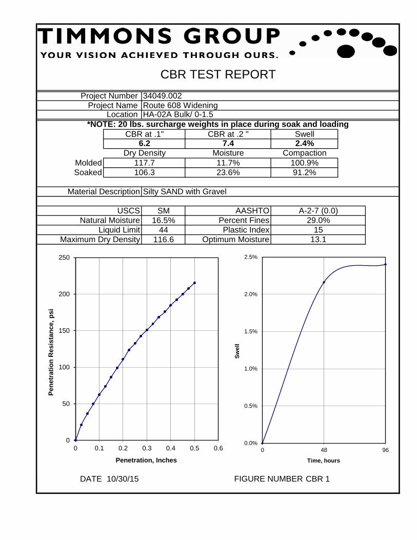
DATE 10/30/15 CBR 1
*NOTE: 20 lbs. surcharge weights in place during soak and loading
Maximum Dry Density Optimum Moisture
A-2-7 (0.0)29.0%
1513.1
AASHTOPercent Fines
91.2%
USCSNatural Moisture
Liquid Limit
Silty SAND with GravelMaterial Description
Soaked 106.3 23.6%
Compaction117.7 11.7% 100.9%
Dry Density MoistureMolded
Location HA-02A Bulk/ 0-1.5
Project Number 34049.002Project Name Route 608 Widening
6.2CBR at .1"
7.4
CBR TEST REPORT
FIGURE NUMBER
CBR at .2 "
Plastic Index
Swell2.4%
0
50
100
150
200
250
0 0.1 0.2 0.3 0.4 0.5 0.6
Pen
etra
tio
n R
esis
tan
ce,
psi
Penetration, Inches
0.0%
0.5%
1.0%
1.5%
2.0%
2.5%
0 48 96
Sw
ell
Time, hours

DATE 10/30/15 GS4FIGURE NUMBER
Natural MoistureSPT Blow Counts
30.4%N/A
HA-04 Bulk/ 0-1
Liquid Limit
60
GRAIN SIZE DISTRIBUTION TEST REPORT
Project Number Project Name
34049.002Route 608 Widening
Location
A-7-5 (4.8)
Percent Gravel Percent Sand Percent Silt and Clay
Plastic Index
27
USCS
SM
28.3% 28.7% 43.0%
Material Description Silty SAND with Gravel
AASHTO
0
10
20
30
40
50
60
70
80
90
100
0.010.1110100
Per
cen
t F
iner
Grain Size - mm
Grain Size Distribution
#4 #10 #200#40

DATE 10/30/15 PR2
Project Number 34049.002Project Name Route 608 Widening
Location HA-04 Bulk/ 0-1
Material Description
27
USCS
60
AASHTO
Silty SAND with Gravel
SM A-7-5 (4.8)
PROCTOR TEST REPORT
107.316.8
FIGURE NUMBER
Maximum Dry Density, pcfOptimum Moisture
Percent FinesPlastic Index
Natural MoistureLiquid Limit
30.4%
Uncorrected Rock Corrected Results93.723.5
43.0%
70.0
80.0
90.0
100.0
110.0
120.0
130.0
0.0% 10.0% 20.0% 30.0% 40.0% 50.0%
Dry
Den
sity
, p
cf
Water Content
Moisture-Density Curve

SM30.4%
60107.3
DATE 10/30/15 CBR 1
*NOTE: 20 lbs. surcharge weights in place during soak and loading
Maximum Dry Density Optimum Moisture
A-7-5 (4.8)43.0%
2716.8
AASHTOPercent Fines
89.4%
USCSNatural Moisture
Liquid Limit
Silty SAND with GravelMaterial Description
Soaked 96.0 30.0%
Compaction108.2 15.3% 100.8%
Dry Density MoistureMolded
Location HA-04 Bulk/ 0-1
Project Number 34049.002Project Name Route 608 Widening
3.1CBR at .1"
3.6
CBR TEST REPORT
FIGURE NUMBER
CBR at .2 "
Plastic Index
Swell4.1%
0
20
40
60
80
100
120
0 0.1 0.2 0.3 0.4 0.5 0.6
Pen
etra
tio
n R
esis
tan
ce,
psi
Penetration, Inches
0.0%
0.5%
1.0%
1.5%
2.0%
2.5%
3.0%
3.5%
4.0%
4.5%
0 48 96
Sw
ell
Time, hours

DATE 10/30/15 GS4FIGURE NUMBER
Natural MoistureSPT Blow Counts
34.0%25+
HA-01/ 1-2
Liquid Limit
54
GRAIN SIZE DISTRIBUTION TEST REPORT
Project Number Project Name
34049.002Route 608 Widening
Location
A-7-5 (1.1)
Percent Gravel Percent Sand Percent Silt and Clay
Plastic Index
15
USCS
SM
14.9% 47.5% 37.7%
Material Description Silty SAND with Gravel
AASHTO
0
10
20
30
40
50
60
70
80
90
100
0.010.1110100
Per
cen
t F
iner
Grain Size - mm
Grain Size Distribution
#4 #10 #200#40

DATE 10/30/15 GS4
6.7% 15.1% 78.2%
Material Description Elastic SILT with Sand
AASHTO
Location
A-7-5 (17.1)
Percent Gravel Percent Sand Percent Silt and Clay
Plastic Index
37
USCS
MH
GRAIN SIZE DISTRIBUTION TEST REPORT
Project Number Project Name
34049.002Route 608 Widening
FIGURE NUMBER
Natural MoistureSPT Blow Counts
31.2%5-5-5
HA-03/ 1-2
Liquid Limit
72
0
10
20
30
40
50
60
70
80
90
100
0.010.1110100
Per
cen
t F
iner
Grain Size - mm
Grain Size Distribution
#4 #10 #200#40

DATE 10/30/15 GS4
12.7% 24.0% 63.3%
Material Description Sandy Elastic SILT
AASHTO
Location
A-7-5 (7.2)
Percent Gravel Percent Sand Percent Silt and Clay
Plastic Index
25
USCS
MH
GRAIN SIZE DISTRIBUTION TEST REPORT
Project Number Project Name
34049.002Route 608 Widening
FIGURE NUMBER
Natural MoistureSPT Blow Counts
38.0%4-4-4
HA-05/ 2-3
Liquid Limit
59
0
10
20
30
40
50
60
70
80
90
100
0.010.1110100
Per
cen
t F
iner
Grain Size - mm
Grain Size Distribution
#4 #10 #200#40

HA-05
3.0
Bag
ELASTIC SILT WITH SAND (MH),orange-brown (Visual) RICH 6.2 940
Sheet 1 of 1
BoringNo.
Summary Of Laboratory TestsAppendix
Description of SoilSpecimen
Project Number:
Notes: 1. Soil tests in general accordance with ASTM standards.2. Soil classifications are in general accordance with ASTM D2487(as applicable), based on testing indicated and visualclassification.3. Key to abbreviations: NP=Non-Plastic; -- indicates no test performed
Project:
Elevationft
Laboratory Testing for TimmonsRoute 60834049.002
SampleType
SampleDepth
ft
DY
NA
MIC
LA
B S
UM
MA
RY
13
613
123
TA
SK
13
LA
B D
AT
A.G
PJ
SC
HN
AB
EL
DA
TA
TE
MP
LAT
E 2
010
_02_
25.
GD
T 1
2/2
2/15
pH
Res
isti
vity
(oh
m-c
m)
Tes
tin
g L
abo
rato
ry

APPENDIX D
PAVEMENT CALCULATIONS


APPENDIX E
Asphalt Core Photo Logs

FIGURE
1ASPHALT CORE
PHOTO LOGROUTE 608 WIDENING
AUGUSTA COUNTY, VA
SCALE:
PLOTTED BY:
DATE:
NTS
CHECKED BY: JNR
JMR
5-6-2016 PROJECT NUMBER: 34049.002
C-01Asphalt 7.5 InchesBase 4.5 Inches
C-02Asphalt 7.0 InchesBase 5.75 Inches** Hand auger refusal in base material

FIGURE
2ASPHALT CORE
PHOTO LOGROUTE 608 WIDENING
AUGUSTA COUNTY, VA
SCALE:
PLOTTED BY:
DATE:
NTS
CHECKED BY: JNR
JMR
5-6-2016 PROJECT NUMBER: 34049.002
C-03Asphalt 5.5 InchesBase 1.75 Inches** Hand auger refusal in base material
C-04Asphalt 6.0 InchesBase 3.0 Inches** Hand auger refusal in base material

FIGURE
3ASPHALT CORE
PHOTO LOGROUTE 608 WIDENING
AUGUSTA COUNTY, VA
SCALE:
PLOTTED BY:
DATE:
NTS
CHECKED BY: JNR
JMR
5-6-2016 PROJECT NUMBER: 34049.002
C-05Asphalt 7.25 InchesBase 1.5 Inches** Hand auger refusal in base material