
REVIEW Recent Progress in Interfacial Toughening and ...
13
Recent Progress in Interfacial Toughening and Damage Self-Healing of Polymer Composites Based on Electrospun and Solution-Blown Nanofibers: An Overview Xiang-Fa Wu, 1 Alexander L. Yarin 2 1 Department of Mechanical Engineering, North Dakota State University, Fargo, North Dakota 58108-6050 2 Department of Mechanical and Industrial Engineering, University of Illinois at Chicago, Chicago, Illinois 60607-7022 Correspondence to: A. L. Yarin (E - mail: [email protected]) or X.-F. Wu (E - mail: [email protected]) ABSTRACT: In this article, we provide an overview of recent progress in toughening and damage self-healing of polymer–matrix com- posites (PMCs) reinforced with electrospun or solution-blown nanofibers at interfaces with an emphasis on the innovative processing techniques and toughening and damage self-healing characterization. Because of their in-plane fiber architecture and layered struc- ture, high-performance laminated PMCs typically carry low interfacial strengths and interlaminar fracture toughnesses in contrast to their very high in-plane mechanical properties. Delamination is commonly observed in these composite structures. Continuous poly- mer and polymer-derived carbon nanofibers produced by electrospinning, solution blowing, and other recently developed techniques can be incorporated into the ultrathin resin-rich interlayers (with thicknesses of a few to dozens of micrometers) of these high-per- formance PMCs to form nanofiber-reinforced interlayers with enhanced interlaminar fracture toughnesses. When incorporated with core–shell healing-agent-loaded nanofibers, these nanofiber-richened interlayers can yield unique interfacial damage self-healing. Recent experimental investigations in these topics are reviewed and compared, and recently developed techniques for the scalable, continuous fabrication of advanced nanofibers for interfacial toughening and damage self-healing of PMCs are discussed. Develop- ments in the near future in this field are foreseen. V C 2013 Wiley Periodicals, Inc. J. Appl. Polym. Sci. 130: 2225–2237, 2013 KEYWORDS: composites; electrospinning and solution-blowing; fibers; mechanical properties; nanostructured polymers Received 6 February 2013; accepted 11 March 2013; Published online 10 May 2013 DOI: 10.1002/app.39282 INTRODUCTION Advanced polymer–matrix composites (PMCs) made of compliant polymeric matrices (typically epoxies) reinforced with high-per- formance fibers (e.g., high-strength carbon fibers) have emerged as lightweight structural materials of choice for many aerospace and aeronautical applications because of their distinct advantages over traditional metallic materials; these advantages include their highly tailorable anisotropic material properties and related high specific strength and stiffness, excellent formability and manufacturability, and superior immunity to corrosion. 1 Advanced PMCs were first developed for high-value military aircraft and spacecraft in the 1970s by the U.S. Air Force. Today, these advanced composites play a crucial role in a wide range of in-service military aerospace and aeronautical systems and reduce the weight by 10–60% over those based on metal designs; a weight reduction of 20–30% is typical of that achieved by the U.S. Air Force B2 bomber and recent F-22 rap- tor (24%). With the maturity of composite technologies, we have witnessed a trend of a rapidly expanding adoption of PMCs in commercial transport aviation in past decades. The new Boeing 787 Dreamliner is made from 50 wt % PMCs and more than 50 vol % PMCs. PMCs are also replacing more and more metal parts in ground vehicles and infrastructures as structural agility, fuel effi- ciency, and material renewability become a worldwide trend and as society also becomes more and more serious about upcoming global challenges, such as the fast depletion of fossil fuel resources and the deterioration of the environment due to the overemission of greenhouse gases and solid wastes. However, there continue to be barriers and challenges to a more expanded exploitation of composite technologies for primary- transport structures; these include damage tolerance, fuel contain- ment, repair and nondestructive inspection, modeling and failure prediction, and cost-effective manufacturing. 2 Current high-per- formance structural PMCs carrying highly anisotropic mechanical properties are typically fabricated by means of prepreg-based vac- uum bag molding or vacuum-assisted resin-transfer molding (VARTM) techniques. In the latter, in-plane fiber fabrics are Corrections added on 28 August 2013, after first online publication. V C 2013 Wiley Periodicals, Inc. WWW.MATERIALSVIEWS.COM WILEYONLINELIBRARY.COM/APP J. APPL. POLYM. SCI. 2013, DOI: 10.1002/APP.39282 2225 REVIEW
Transcript of REVIEW Recent Progress in Interfacial Toughening and ...
Recent Progress in Interfacial Toughening and Damage Self-Healing ofPolymer Composites Based on Electrospun and Solution-BlownNanofibers: An Overview
Xiang-Fa Wu,1 Alexander L. Yarin2
1Department of Mechanical Engineering, North Dakota State University, Fargo, North Dakota 58108-60502Department of Mechanical and Industrial Engineering, University of Illinois at Chicago, Chicago, Illinois 60607-7022Correspondence to: A. L. Yarin (E - mail: [email protected]) or X.-F. Wu (E - mail: [email protected])
ABSTRACT: In this article, we provide an overview of recent progress in toughening and damage self-healing of polymer–matrix com-
posites (PMCs) reinforced with electrospun or solution-blown nanofibers at interfaces with an emphasis on the innovative processing
techniques and toughening and damage self-healing characterization. Because of their in-plane fiber architecture and layered struc-
ture, high-performance laminated PMCs typically carry low interfacial strengths and interlaminar fracture toughnesses in contrast to
their very high in-plane mechanical properties. Delamination is commonly observed in these composite structures. Continuous poly-
mer and polymer-derived carbon nanofibers produced by electrospinning, solution blowing, and other recently developed techniques
can be incorporated into the ultrathin resin-rich interlayers (with thicknesses of a few to dozens of micrometers) of these high-per-
formance PMCs to form nanofiber-reinforced interlayers with enhanced interlaminar fracture toughnesses. When incorporated with
core–shell healing-agent-loaded nanofibers, these nanofiber-richened interlayers can yield unique interfacial damage self-healing.
Recent experimental investigations in these topics are reviewed and compared, and recently developed techniques for the scalable,
continuous fabrication of advanced nanofibers for interfacial toughening and damage self-healing of PMCs are discussed. Develop-
ments in the near future in this field are foreseen. VC 2013 Wiley Periodicals, Inc. J. Appl. Polym. Sci. 130: 2225–2237, 2013
KEYWORDS: composites; electrospinning and solution-blowing; fibers; mechanical properties; nanostructured polymers
Received 6 February 2013; accepted 11 March 2013; Published online 10 May 2013DOI: 10.1002/app.39282
INTRODUCTION
Advanced polymer–matrix composites (PMCs) made of compliant
polymeric matrices (typically epoxies) reinforced with high-per-
formance fibers (e.g., high-strength carbon fibers) have emerged as
lightweight structural materials of choice for many aerospace and
aeronautical applications because of their distinct advantages over
traditional metallic materials; these advantages include their highly
tailorable anisotropic material properties and related high specific
strength and stiffness, excellent formability and manufacturability,
and superior immunity to corrosion.1 Advanced PMCs were first
developed for high-value military aircraft and spacecraft in the
1970s by the U.S. Air Force. Today, these advanced composites play
a crucial role in a wide range of in-service military aerospace and
aeronautical systems and reduce the weight by 10–60% over those
based on metal designs; a weight reduction of 20–30% is typical of
that achieved by the U.S. Air Force B2 bomber and recent F-22 rap-
tor (24%). With the maturity of composite technologies, we have
witnessed a trend of a rapidly expanding adoption of PMCs in
commercial transport aviation in past decades. The new Boeing
787 Dreamliner is made from 50 wt % PMCs and more than 50
vol % PMCs. PMCs are also replacing more and more metal parts
in ground vehicles and infrastructures as structural agility, fuel effi-
ciency, and material renewability become a worldwide trend and as
society also becomes more and more serious about upcoming
global challenges, such as the fast depletion of fossil fuel resources
and the deterioration of the environment due to the overemission
of greenhouse gases and solid wastes.
However, there continue to be barriers and challenges to a more
expanded exploitation of composite technologies for primary-
transport structures; these include damage tolerance, fuel contain-
ment, repair and nondestructive inspection, modeling and failure
prediction, and cost-effective manufacturing.2 Current high-per-
formance structural PMCs carrying highly anisotropic mechanical
properties are typically fabricated by means of prepreg-based vac-
uum bag molding or vacuum-assisted resin-transfer molding
(VARTM) techniques. In the latter, in-plane fiber fabrics are
Corrections added on 28 August 2013, after first online publication.
VC 2013 Wiley Periodicals, Inc.
WWW.MATERIALSVIEWS.COM WILEYONLINELIBRARY.COM/APP J. APPL. POLYM. SCI. 2013, DOI: 10.1002/APP.39282 2225
REVIEW

commonly used and constitute the reinforcing framework of the
resulting PMCs after resin infusion and curing. The in-plane fiber
architecture can benefit extremely from the in-plane uniaxial or
biaxial mechanical properties of high-performance laminated
PMCs, which can reach those of high-strength steels and alloys.
However, compared to their superior in-plane mechanical prop-
erties, the out-of-plane properties of advanced PMCs are typically
very low; these properties include the interfacial shear strength
and interlaminar fracture toughness. Microscopic imaging of the
cross sections of advanced PMCs have indicated that there exist
ultrathin resin-rich interlayers with thicknesses of a few to dozens
of micrometers between neighboring plies (laminas). Such inter-
layers carry a very low strength and fracture toughness, especially
for thermosetting laminated PMCs. In fact, interlaminar fracture
(delamination) has commonly been observed in these composite
structures, and this has been a focus of research since the birth
of advanced laminated composites in the 1970s.3,4 A variety of
toughening techniques have been reported in the literature, spe-
cifically aimed at the suppression of the interfacial failure of
advanced PMCs; these are reviewed briefly later.
On the other hand, electrospinning as a low-cost, top-down
nanofabrication technique has been investigated extensively in the
last decade;5–10 this technique is capable of the scalable produc-
tion of high-strength, tough continuous polymers and polymer-
derived carbon nanofibers (CNFs). These nanofibers can be incor-
porated into the ultrathin resin-rich interlayers of laminated
PMCs to form nanofiber-reinforced interlayers with a high
strength and fracture toughness. In addition, when incorporated
into core–shell healing-agent-loaded nanofibers, nanofiber-tough-
ened interlayers in laminated PMCs can carry unique interfacial
damage self-healing, as we demonstrated recently.11,12 In this
review, we summarize recent experimental investigations on inter-
facial toughening and damage self-healing techniques based on
electrospun nanofibers, particularly for high-performance-fiber
(e.g., carbon and glass fibers)-reinforced laminated PMCs. There
are two main focuses: (1) the interfacial toughening and damage
self-healing mechanisms based on electrospun nanofibers and (2)
the high-efficiency, scalable fabrication of continuous core–shell
healing-agent-loaded nanofibers by electrospinning and other
recently developed low-cost fabrication techniques. The rest of
this article consists of the following. In the second section, we
present a comparative review of the interfacial failure of lami-
nated PMCs and their conventional toughening techniques. In
the third section, we summarize the recent experimental progress
in interfacial toughening and damage self-healing of laminated
PMCs based on electrospun nanofibers. In the fourth section, we
report on the recent progress in core–shell nanofiber fabrication,
which is particularly important to the production of continuous
core–shell healing-agent-loaded nanofibers uniquely for localized
interfacial damage self-healing with low costs and low weight pen-
alties. A brief prospective and concluding remarks on the
reviewed topics are contributed in the fifth section.
INTERFACIAL FAILURE OF PMCS AND FAILURESUPPRESSION TECHNIQUES
Because of the heterogeneous nature of fiber-reinforced lami-
nated PMCs, the stress–strain field and resulting failure process
in laminated PMCs are extremely inhomogeneous. Typically, a
locus with the severe stress state may lead to early microda-
mages (e.g., damage nucleation) in PMCs.13 The inhomogeneity
of the stress–strain field and the randomness of the strength–
toughness of composite constituents result in the typical failure
process of laminated PMCs, such as a progressive failure of
microcrack nucleation, matrix cracking, fiber breakage, fiber
and matrix debonding, and delamination.1,14 The typical dam-
age modes in a cross-ply PMC laminate are illustrated in Figure
1; these include matrix cracking, fiber–matrix debonding, fiber
breakage, and delamination. Delamination is a macroscopic fail-
ure phenomenon, which is usually the combination of one or
several microscopic failure modes. In reality, the damage/failure
process in PMCs is much more complicated and is highly de-
pendent on the type of load, fiber, and ply architecture and the
physical properties of the constituents. In principle, the strength
and toughness of PCMs are the combined effect of the strength
and fracture toughness of the constituents (i.e., the reinforcing
fibers and polymeric matrix), fiber–matrix interfacial properties
(e.g., interfacial physical and chemical properties, roughness),
the microstructure of the composite (e.g., fiber alignment, ply
layup, volume fraction), dominant failure modes, and stress
inhomogeneity (e.g., stress concentration). Given a fiber–matrix
combination, a practicable toughening technique, which could
enhance the strength and toughness of the resulting PMC sys-
tem, needs to address one or several dominating factors at an
affordable cost.
In the past 4 decades, quite a few effective toughening techni-
ques and concepts have been formulated and implemented in
PMCs; these include free-edge-delamination–suppression
designs,1 laminate stitching,15 modification of matrix resins by
incorporation with rigid/rubbery microparticles/nanopar-
ticles,16,17 controlled fiber debonding and fiber surface treat-
ments,18 interleaving,19 and so on. Among these, free-edge-
delamination–suppression concepts (e.g., edge reinforcement
and edge modification) belong to laminate design at the ply
level in altering the singular stress field near the laminate
edges;1–3 this is not closely relevant to materials science, how-
ever, but more to accurate free-edge stress analysis.20 Interleav-
ing is based on the incorporation of discrete thin layers of
tough resins, particulates, whiskers, or microfibers into interfa-
ces between neighboring plies of PMCs.19,21–26 The interleaved
tough resin (typically thermoplastic epoxy) carries a high shear
failure strain and provides enhanced fracture toughness at the
Figure 1. Schematic damage modes in a cross-ply PMC laminate: (1)
reinforcing fibers, (2) fiber breakage, (3) matrix cracking, (4) fiber/matrix
debonding, and (5) delamination. Reprinted with permission from ref. 12.
Courtesy of Wiley Periodicals. [Color figure can be viewed in the online
issue, which is available at wileyonlinelibrary.com.]
REVIEW
2226 J. APPL. POLYM. SCI. 2013, DOI: 10.1002/APP.39282 WILEYONLINELIBRARY.COM/APP

laminate interfaces to suppress delamination. The impact and
fatigue damage tolerance of carbon fiber–epoxy laminates can
also be noticeably improved23–26 via the allowance of redundant
shear strains along the ply interfaces, which accommodate the
strain mismatch across the laminate interfaces. Interleaving has
been used in structural laminated PMCs. However, the thickness
of the plastic interleaf is typically comparable to the ply thick-
ness, and this may result in an obvious increase in the laminate
thickness and, therefore, a decrease in the unique high specific
strength and stiffness of advanced PMCs. Thus, the search for
new interfacial toughening techniques with low costs, low
weight penalties, and high specific properties of PMCs contin-
ues. In addition, all of the previous interfacial toughening tech-
niques do not carry the damage self-healing function. As a
matter of fact, the interfacial shear strength and interlaminar
fracture toughness of laminated PMCs always degrade with
elapsing time, and this has attracted substantial attention of
researchers to explore the recent progress in self-healing materi-
als27–37 for interfacial toughening and damage self-healing of
laminated PMCs at low costs and with a low weight penalty.
NANOTECHNOLOGY-BASED INTERFACIAL TOUGHENINGTECHNIQUES FOR LAMINATED PMCS
Since the discovery of single-walled crystalline carbon nanotubes
(CNTs) in 1991,38 materials scientists have generally believed
that composites made with nanoscale reinforcing materials (e.g.,
CNTs, platelets, nanoparticles) will carry exceptional mechanical
properties superior to those of traditional composites. Although
CNTs at a small volume fraction mixed with resins have resulted
in remarkable increases in electrical and thermal conductivities
triggered by their unique percolation effect, the improvements
in the mechanical properties obtained so far are still rather dis-
appointing, particularly when they are compared to those of
advanced PMCs reinforced with high-performance continuous
fibers.39–43 Several possible mechanisms have been identified
that are responsible for such poor improvements, including
inadequate dispersion and alignment of the nanoreinforcing ele-
ments, low volume fraction, poor bonding, and insufficient
load-transfer properties at the interfaces.43 In addition, the ten-
sile strengths of CNTs and CNFs may also be much lower than
their theoretical predictions because of the unavoidable struc-
tural defects induced in the synthesis process and surface dop-
ing. So far, despite the extensive research efforts in structural
nanocomposites, the prospect of high-strength and high-tough-
ness structural nanocomposites still seems to be remote. How-
ever, recent research in nanomanufacturing and nanocomposites
has accumulated significant encouraging results in the reinforce-
ment of a small portion of the materials that can be transferred
to enhance the mechanical properties of conventional structural
PMCs at low cost, low weight penalty, and low impact to the
high specific properties of PMCs.43–50 Among these, interfacial
toughening and damage self-healing of PMCs based on electro-
spun polymers and polymer-derived CNFs have been one of the
focuses in the last decade. Substantial experimental works have
been performed on controlled nanofiber fabrication, optimal
processing of hybrid multiscale composites, and related tough-
ening and damage self-healing characterization.
So far, electrospinning as a low-cost, top-down electrohydrody-
namic nanofabrication technique has been used to produce a
variety of polymer and polymer-derived nanofibers for broad
applications, including nanocomposites, filter media, tissue scaf-
folds, and so on.51–55 Recent nanomechanical characterization
has indicated that when the diameter is below certain values
(from one to a few hundred nanometers), electrospun polymer
nanofibers exhibit obviously improved strengths and much
higher toughnesses compared to their microfiber and buck
counterparts.56–60 Several potential mechanisms could be re-
sponsible for such obvious size effects, and these are still under
intensive investigation; these include surface energy, polymer
chain alignment, improved crystallinity, and more.61–64 These
low-cost continuous nanofibers provide an excellent nanorein-
forcing material for the localized interfacial toughening of
PMCs. Among others, Kim and Reneker65 were the first to pro-
duce polymer nanocomposites reinforced with electrospun
nanofibers. In their study, chopped electrospun polybenzimida-
zole (PBI) nanofibers (diameter � 300 nm) were used to
toughen styrene–butadiene rubber (SBR). Their experiments
showed that at a PBI mass ratio of 15%, short PBI nanofiber-
toughened SBRs had an average Young’s modulus of 19.6 MPa
and a tensile strength of 2.8 MPa compared to values of 1.8 and
2.1 MPa, respectively, for the virgin SBR. Nearly a 10-fold mod-
ulus improvement and a 70% tensile strength improvement
were obtained. Furthermore, Dzenis and Reneker44 patented the
idea of novel delamination-resistant composites prepared by the
introduction of small-diameter fibers at ply interfaces, where
the electrospun nanofibers were first considered as candidates
for interfacial toughening in structurally laminated PMCs [Fig-
ure 2(a)].
Furthermore, in his thesis work at the University of Nebraska–
Lincoln (Yuris Dzenis’s group), Wu49 conducted systematic
studies on the interfacial toughening effect in an aerospace-
grade laminated PMC made of unidirectional carbon fiber/ep-
oxy prepregs (Toray P7051S-20Q-F250, Toray America, Califor-
nia) in a wide loading rate from quasistatic and cyclic to
dynamic and impact. In the investigation, nonwoven polymer
nanofibers [polyacrylonitrile (PAN)] were produced by electro-
spinning a 10 wt % PAN/N,N-dimethylformamide (DMF) solu-
tion and directly deposited onto the prepreg sheet with a
controlled thickness before the laminate panel layup. After vac-
uum bag molding, the PAN nanofibers were integrated into the
resin-rich interlayers to form nanofiber-reinforced interlayers. In
quasistatic pure-mode fracture tests based on double-cantilever
beam and end-notched flexural specimens, it was found that
the PAN nanofibers could enhance the pure-mode fracture
toughness by about 30%. A fractographical analysis of the failed
samples showed that the toughening mechanisms could include
nanofiber pullout, breakage, bridging, and plastic-nanofiber-
induced interfacial softening [Figure 1(e,f)].49 To examine the
toughening effect on the edge-delamination strength of lami-
nated PMCs, an angle-ply laminated composite reinforced with
nonwoven PAN nanofibers at its interfaces was employed, in
which the ply layup was optimized as [122/2122/02] to maxi-
mize the out-of-plane shear stress at a given effective axial
strain.20 Although the onset stress for edge delamination and
REVIEW
WWW.MATERIALSVIEWS.COM WILEYONLINELIBRARY.COM/APP J. APPL. POLYM. SCI. 2013, DOI: 10.1002/APP.39282 2227

the ultimate tensile strength of the virgin and nanofiber-tough-
ened specimens were highly scattered, statistical analysis of the
experimental data indicated obvious improvements in both the
delamination onset stress and the ultimate tensile strength [Fig-
ures 2(b,c)]. The unusual increase in the ultimate tensile
strength of the tested composite laminate through the addition
of a tiny amount of PAN nanofibers (volume fracture <1%) at
the 12�/212� interface was attributed to a plastic softening
effect by the plastic nanofibers. Moreover, comparative tension–
tension fatigue tests of the same laminated PMCs with and
without PAN nanofiber reinforcements indicated that the addi-
tion of a tiny amount of plastic PAN nanofibers at the laminate
interfaces nearly doubled the cycles of the fatigue lifetime [Fig-
ure 2(d)]; this was an exceptional enhancement to the fatigue
damage tolerance. Instrumented dynamic fracture tests based on
a Hopkinson pressure bar also confirmed the toughening effect
of the PAN nanofibers on the dynamic delamination toughness
of a thick laminated composite made of 96 unidirectional plies
(Toray P7051S-20Q-F250, Toray America).
To extend the previous interfacial toughening method for fiber-
reinforced PMCs produced by the low-cost VARTM technique,
Fong and coworkers66–69 recently performed substantial studies
of the toughening effect of ultrathin nonwoven CNFs on the
interfacial mechanical properties of laminated PMCs. Ultrathin
CNF mats were prepared by electrospinning PAN nanofibers,
followed by thermal treatments, including stabilization at 280�Cin air and carbonization at 1200�C in an argon environment.66
To process the novel hybrid multiscale PMC laminates, the
ultrathin CNF mats were first placed on the woven fabric before
resin infusion during the VARTM process. After resin infusion
and curing, the CNF mats formed toughened interlayers. Three-
point flexural and short-beam tests were adopted to evaluate
the toughening effect on the out-of-plane mechanical properties
of the novel hybrid multiscale composites. The experimental
results showed that ultrathin CNF mats at interfaces nearly
doubled the interlaminar shear strength, whereas the flexural
modulus and work of fracture did not show significant
improvements.66 The authors further considered the toughening
effect of CNF mats with different thicknesses and found that
the toughening effect could be maximized only at a certain
thickness of the CNF layer, which was measured in terms of a
nanofiber collecting time around 10 min in their particular ex-
perimental setup.69 In addition, Zhang et al.70 evaluated the
toughening effect of different types of polymer nanofibers on
the mode I interlaminar fracture toughness of hybrid multiscale
carbon-fiber fabric/epoxy composites with interfaces reinforced
with electrospun polymer nanofibers. Three types of polymer
Figure 2. (a) Conceptual hybrid multiscale PMC reinforced with electrospun continuous nanofibers at the interfaces (Reprinted with permission from
ref. 43. Copyright 2008 American Association for the Advancement of Science.). (b–d) Toughening effect in edge-delamination onset stress, ultimate
toughness strength, and fatigue lifetime of the angle-ply composite laminate with a layup [122/2122/02]s.49 (e) Scanning electron microscopy (SEM)
micrograph of the nanofibers entangled at the ply surface after delamination failure. (f) SEM micrograph of the electrospun nanofibers and reinforcing
carbon microfibers entangled at the ply surface after delamination failure. The unidirectional carbon fiber/epoxy prepregs (Toray P7051S-20Q-F250)
used in the tests were supplied by Toray America Composites.49 [Color figure can be viewed in the online issue, which is available at
wileyonlinelibrary.com.]
REVIEW
2228 J. APPL. POLYM. SCI. 2013, DOI: 10.1002/APP.39282 WILEYONLINELIBRARY.COM/APP

nanofibers were fabricated and adopted for the evaluations, i.e.,
poly(E-caprolactone), poly(vinylidene fluoride), and PAN. Their
results indicate that poly(vinylidene fluoride) and PAN demon-
strated indiscernible toughening effects; however, the poly(E-
caprolactone) nanofibers showed an obvious toughening effect
at three different fiber diameters (average), with the improve-
ment as high as 55%, depending on the fiber diameter.
The main advantages of the above interfacial toughening techni-
ques include the low cost in nanofiber fabrication, low weight
penalty to the superior specific strength and stiffness of the
PMCs because the toughening nanofibers are highly localized at
interfaces, and low impact to the PMC processing such that this
interfacial toughening method can be conveniently merged into
the conventional PMC process. Thus, this interfacial toughening
should have a promising future in PMC industries. However,
like all conventional toughening techniques, this nanofiber-
based interfacial toughening technique does not carry any dam-
age self-healing function. The interfacial mechanical properties
will irreversibly degrade with time. This has recently raised the
attention of researcher to resolve this issue.
BIO-INSPIRED INTERFACIAL DAMAGE SELF-HEALING FORLAMINATED PMCS
In nature, biological bodies have evolved various self-protection
functionalities to self-heal damage and function failure (e.g.,
bleeding, blood clotting, tissue bruising, tree bark compartmen-
talization healing); this has inspired the development of several
damage self-healing mechanisms exploited for use in engineer-
ing materials.35 The exploration of self-healing engineering
materials can be tracked to works by Dry and Sottos71–73 in the
early 1990s, where a systematic route was described for achiev-
ing self-healing materials.74 Significant progress in self-healing
materials has been made in the last decade after the seminal
work on autonomic healing composites based on encapsulated
healing agents by White et al.27 in 2001. Recently, a few
comprehensive reviews have been done on the processing of
general self-healing materials and composites, damage-healing
mechanisms, and related experimental evaluations and model-
ing.29,74,75 According to the individual damage-healing mecha-
nisms, self-healing polymeric materials and composites can be
classified as follows: (1) self-healing thermoplastic materials
based on polymer chain interdiffusion, temperature/photo/UV-
induced fusion, and so on, which rely mainly on the high mo-
bility and reactivity of the polymer chains in such materials,
and (2) self-healing thermoset materials based on passive me-
chanical-damage-induced living ring-opening metathesis poly-
merization (ROMP), in which the healing agent is stored in
microcapsules,27,32,33 hole glass fibers,35,36 engineered microvas-
cular networks,76 and so on. In addition, shape-memory poly-
mers and shape-memory polymer/alloy wires have also recently
been adopted in self-healing polymeric materials to generate no-
ticeable clamping forces for effective crack closure during the
damage-healing process;77–82 however, external disturbances
(e.g., electric current, cooling, heating) are thought to trigger
the desired shape-memory effects during the damage-healing
process. Thus, additional effort is still needed to incorporate
such healing mechanisms into engineered materials and
composites.
Among these, two mechanisms based on mammal bleeding
strategy have been investigated extensively in recent years. The
first is the microencapsulation approach, in which the self-heal-
ing system is based on ROMP;27,32,33 the second is the use of
hollow microfibers containing a healing agent with the same
ROMP reaction.35,36 In principle, the microencapsulation
approach involves the incorporation of a microencapsulated
healing agent and dispersed catalyst particles within the poly-
meric matrix. Upon cracking, the wax-type microcapsules are
ruptured by the propagating crack fronts, and this results in the
autonomous release of the healing agent into the crack surfaces
through capillary action, as illustrated in Figure 3. The subse-
quent ROMP of the healing agent (a polymer monomer) trig-
gered by catalyst particles embedded in the matrix heals the
material and prevents further crack growth. Dicyclopentadiene
(DCPD; C10H12) and Grubbs’ catalyst have been used broadly
as the self-healing system that has been mostly studied for use
in PMCs.83 DCPD is in a liquid state at room temperature and
carries a low viscosity; the related ROMP happens rapidly once
the Grubbs’s catalyst is met, typically in a few seconds to a few
minutes, which is suitable for structural damage self-healing.
In addition, damage self-healing mechanisms based on hollow
fibers embedded within an engineering material are similar to
the arteries in a natural system.35,36 To incorporate the hollow
glass fibers carrying a healing agent into composites, commer-
cially available hollow glass fibers have been demonstrated; they
can be directly consolidated into laminas and then manufac-
tured into composite laminates; that is, the self-healing system
can also function as a reinforcing element.35 The key advantages
of the hollow fiber self-healing concept are that the fibers can
be located to match the orientation of the surrounding reinforc-
ing fibers and thereby minimize the effect of the Poisson’s ratio
and the mismatch of properties between the self-healing net-
work and the reinforcing fibers. In addition, the fibers can be
placed at any location within the stacking sequence to address
specific failure threats (Figure 4).
It has been a challenge to directly exploit the previous damage
self-healing mechanisms for the interfacial damage self-healing
of laminated PMCs because of the large size of the microcap-
sules and hollow microfibers, which cannot be conveniently
integrated into the resin-rich interlayers with their thicknesses
of a few to dozens of micrometers. In fact, the relatively large
size of the microcapsules (10–1000 lm) may induce additional
problems when the microcapsules are integrated into laminated
PMCs; these potential problems include the disruption of the
fiber architecture (i.e., fiber waviness and fiber volume fraction),
the need for a good dispersion of the catalyst to provide uni-
form healing functionality, microcapsule confinement in a limit-
ing resin volume, and creation of a void in the wake of cracking
after the consumption of healing agent.35 Also, a large volume
fraction of microcapsules in the matrix will adversely decrease
the unique high specific stiffness and strength of the high-per-
formance PMCs. Additionally, some results have also indicated
specific problems in terms of healing efficiency due to the
REVIEW
WWW.MATERIALSVIEWS.COM WILEYONLINELIBRARY.COM/APP J. APPL. POLYM. SCI. 2013, DOI: 10.1002/APP.39282 2229

clumping of microcapsules into woven–roving wells, where
cracks propagate along the woven–roving peaks. Therefore, an
optimal damage self-healing strategy is expected to be able to
locate and autonomously release healing agent at specific loci of
the composites where cracking and damage are most likely to
occur, such as at the laminate interfaces.
To resolve this technical challenge, we recently proposed the use
of such recently developed fabrication techniques as co-electro-
spinning, emulsion electrospinning, and solution blowing (see
the fourth section) to enwrap the liquid healing agent (e.g.,
DCPD) into ultrathin polymer nanofibers with the diameter of
a couple of micrometers down to hundreds of nanometers.11,12
As a result, ultrathin nonwoven healing-agent-loaded nanofiber
mats can be obtained with tailorable fiber diameters and mor-
phologies through the adjustment the material and process
parameters. In one study, wet layup followed by the VARTM
technique was used to process hybrid multiscale carbon-fiber/
epoxy PMCs (layup: [0�/645�/90�]) reinforced with ultrathin
healing-agent-loaded core–shell nanofiber mats,12,84 in which
Epon 862 epoxy resin with Epicure 3234 curing agent was
selected as the polymeric matrix. It was expected that once
delamination occurred, the crack-scissored core–shell nanofibers
and liquid healing agent would be autonomously released on
the delaminated surface. In the study, a three-point-bending test
was adopted to evaluate the damage-healing efficiency of the
composite laminate after predamage. The healing efficiency was
defined by the flexural stiffness recovery ratio as follows:12,84
Stiffness recovery ratio5Healed flexural stiffness
Initial flexural stiffness3100% (1)
Figure 4. (a) Hollow glass fibers, (b) hollow glass fibers embedded in cross-ply carbon-fiber/epoxy composite laminate, and (c) damage visualization
enhancement in a composite laminate by the bleeding mechanism of a fluorescent dye released from hollow glass fibers. Reprinted from ref. 35. Copy-
right 2007 the Institute of Physics. [Color figure can be viewed in the online issue, which is available at wileyonlinelibrary.com.]
Figure 3. (a) Microencapsulated healing agent embedded in a polymeric matrix containing a catalyst capable of polymerizing the healing agent: (i) cracks
formed in the matrix wherever damage occurred; (ii) the crack ruptured the microcapsules, releasing the healing agent into the crack plane through cap-
illary action (the Lucas–Washburn mechanism); and (iii) the healing agent contacted the catalyst triggering polymerization that bound the crack faces
closed. (b) SEM image of the fracture plane of a self-healing epoxy with a ruptured urea–formaldehyde microcapsule. Reprinted with permission from
ref. 27. Copyright 2001 Macmillan, Ltd. [Color figure can be viewed in the online issue, which is available at wileyonlinelibrary.com.]
REVIEW
2230 J. APPL. POLYM. SCI. 2013, DOI: 10.1002/APP.39282 WILEYONLINELIBRARY.COM/APP
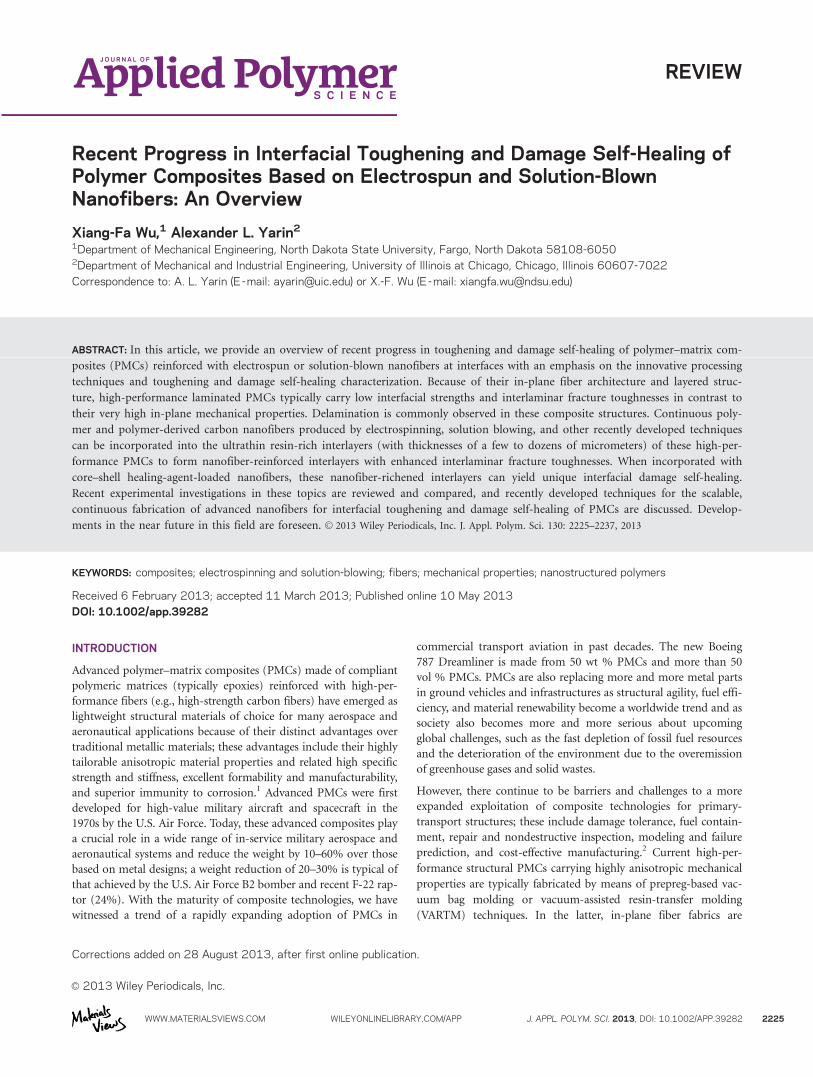
Controlled experiments in the study indicated that after the
three-point predamage test, the flexural stiffness was decreased
substantially from the original 144.8–163.9 kN/m down to 46.3–
61.2 kN/m. After 2 h of damage healing under free-loading con-
ditions, the as-healed stiffness was increased up to 99.0–159.0
kN/m, a nearly 70–100% stiffness recovery.12,84 Scanning electron
microscopy (SEM) based fractographical analysis of the failed
surface of the samples indicated the autonomous release of the
healing agent (DCPD) at the delaminated surface (Figure 5). Af-
ter the ROMP reaction, these polymerized DCPDs functioned as
discrete pins to bind the delaminated surfaces. In addition, plas-
tic deformation could be clearly differentiated at the healed spots
(after final failure), corresponding the substantial shear strains
during three-point flexural tests; this allowed significant interfa-
cial strain mismatches particularly popular in laminated PMCs.
Similarly, these plastic core–shell nanofibers could also function
as toughening nanofibers before scission and similar to the ho-
mogeneous toughening nanofibers discussed previously.12
Herein, the healing-agent-loaded core–shell nanofibers used for
interfacial damage self-healing of laminated PMCs have just
started to come into vision. Similar to other self-healing materi-
als and interfacial toughening schemes in laminated PMCs, sig-
nificant research effects are expected in the near future to
determine the fundamentals of the entire process, including the
controlled fabrication of healing-agent-loaded core–shell nano-
fibers, healing-agent delivery, toughening and damage self-heal-
ing mechanisms, and optimal design of self-healing laminated
PMCs.
HIGH-EFFICIENCY FABRICATION OF CORE–SHELLHEALING-AGENT-LOADED NANOFIBERS
Coaxial electrospinning (co-electrospinning) was developed as a
technique allowing the formation of core–shell micrometer-sized
fibers and nanofibers using electrified jets of polymer solu-
tions.85 The physical mechanism of co-electrospinning is similar
to that of electrospinning. It is based on the electrically driven
bending instability of electrified jets and is a particular example
of the Earnshaw’s instability in electrostatics.86,87 The bending
instability results in a fractal-like configuration of a polymer jet
in flight, and the corresponding enormous length, which it
Figure 5. SEM micrographs of the failed surfaces of the hybrid multiscale self-healing PMC after the three-point-bending test (interfacial self-healing
mechanisms): (a,b) core–shell nanofiber networks (the circled spots are the regions with autonomously released DCPD after predamage failure) and
(c,d) delivery of the healing agent at the core–shell nanofiber breakages due to interfacial and plastic failure of the healed spots after the three-point-
bending test.12,84 Copyright Wiley Periodicals. [Color figure can be viewed in the online issue, which is available at wileyonlinelibrary.com.]
REVIEW
WWW.MATERIALSVIEWS.COM WILEYONLINELIBRARY.COM/APP J. APPL. POLYM. SCI. 2013, DOI: 10.1002/APP.39282 2231
acquires at about a 10-cm distance from the needle to the col-
lector. As a result, the jet stretches at the rate on the order of
103 s21 and becomes very thin, whereas the viscoelasticity pre-
vents capillary breakup. In parallel, the solvent evaporates, the
polymer precipitates and solidifies, and thus, nanofibers are
formed.
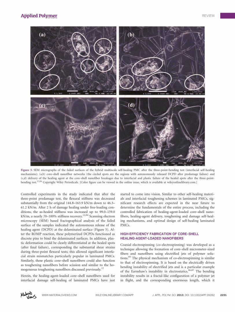
In co-electrospinning, two polymer solutions are supplied to
the core–shell needle separately (Figure 6). At the exit of the
core–shell needle attached to the double-compartment syringe
emerges a core–shell droplet.88,89 The droplet is stretched by the
electric Maxwell stresses directed toward the counter electrode,
and in supercritical regimes when the electric pulling overcomes
the surface tension and viscoelastic resistance, a core–shell jet is
issued from its tip.90 It is subjected to the bending instability
discussed previously. Several reviews have recently been devoted
to electrospininning91–93 and have shown that this technique is
widely used by many research groups.
A simplified version of co-electrospinning, which does not
require a core–shell needle, two separate syringe pumps, and
pipelines for supplying two polymer solutions, can be realized
with a standard electrospinning setup but with its application to
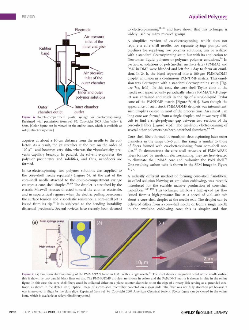
Newtonian liquid–polymer or polymer–polymer emulsions.94 In
particular, solutions of poly(methyl methacrylate) (PMMA) and
PAN in DMF were blended and left for 1 day to form an emul-
sion. In 24 h, the blend separated into a 100-lm PMMA/DMF
droplet emulsion in a continuous PAN/DMF matrix. This emul-
sion was electrospun with a standard electrospinning setup [Fig-
ure 7(a, left)]. In this case, the core–shell Taylor cone at the
needle exit appeared only periodically when a PMMA/DMF drop-
let was entrained and stuck in the tip of a single-liquid Taylor
cone of the PAN/DMF matrix [Figure 7(left)]. Even though the
appearance of such stuck PMMA/DMF droplets was intermittent,
such droplets existed in most of the process time. An almost 1 m
long core was formed from a single droplet, and it was very diffi-
cult to find a single-polymer gap between two sections of the
core–shell fiber [Figure 7(b)]. The emulsion electrospinning of
several other polymers has been described elsewhere.95–99
Core–shell fibers formed by emulsion electrospinning have outer
diameters in the range 0.5–5 lm; this range is similar to those
of fibers formed with co-electrospinning from core–shell nee-
dles.85 To demonstrate the core–shell structure of PMMA/PAN
fibers formed by emulsion electrospinning, they are heat-treated
to eliminate the PMMA core and carbonize the PAN shell.94
One resulting carbon tube is shown in the SEM image in Figure
7(c).
A radically different method of forming core–shell nanofibers,
so-called solution blowing or emulsion coblowing, was recently
introduced for the scalable massive production of core–shell
nanofibers.100–103 This technique employs a high-speed gas flow
issued from a high-pressure line at a speed of 200–300 m/s
about a core–shell droplet at the needle exit. The droplet can be
delivered either from a core–shell needle or from a single needle
in the emulsion coblowing case; this is simpler and thus
Figure 6. Double-compartment plastic syringe for co-electrospinning.
Reprinted with permission from ref. 85. Copyright 2003 John Wiley &
Sons. [Color figure can be viewed in the online issue, which is available at
wileyonlinelibrary.com.]
Figure 7. (a) Emulsion electrospinning of the PMMA/PAN blend in DMF with a single needle.94 The inset shows a magnified detail of the needle orifice;
this is shown by two parallel black lines on top. The PMMA/DMF droplets are shown in yellow and the PAN/DMF matrix is shown in blue in the online
figure. In this case, the core–shell fibers could be collected either on a plane counter electrode or on the edge of a rotary disk serving as a grounded elec-
trode, as shown in the sketch. (b,c) Optical image of a core–shell microfiber collected on a glass slide. The fiber was not fully stretched yet because it
was intercepted in flight by the glass slide. Reprinted from ref. 94. Copyright 2007 American Chemical Society. [Color figure can be viewed in the online
issue, which is available at wileyonlinelibrary.com.]
REVIEW
2232 J. APPL. POLYM. SCI. 2013, DOI: 10.1002/APP.39282 WILEYONLINELIBRARY.COM/APP

preferable. The droplet driven by the gas jet stretches and issues
a core–shell jet from its tip. The latter is stretching and bending
vigorously under the action of the gas flow as a result of the
aerodynamically driven bending instability.104,105 The jet cross-
sectional diameter rapidly reduces to the nanoscale, which after
the solvent evaporates, results in nanofibers. The productivity of
Figure 8. Optical images of the co-electrospun core–shell DCPD/PAN nanofibers.11 Panel (a) shows relatively uniform nanofibers, whereas panel (b)
depicts nanofibers affected by capillary instability visible as a series of undulations. The scale bar in both images is 5 lm. Reprinted from ref. 11. Copy-
right 2012 Royal Society of Chemistry. [Color figure can be viewed in the online issue, which is available at wileyonlinelibrary.com.]
Figure 9. Optical images of the core–shell emulsion–electrospun fibers.11 (a,b) Core–shell fibers formed from the emulsion of DCPD in PAN and DMF,
with DCPD eventually occupying the core and PAN (the shell). (c,d) Core–shell fibers formed from the emulsion of PAN and IPDI in DMF, with PAN
eventually occupying the shell and the IPDI (the core). The scale bar in all of the images is 10 lm. Reprinted from ref. 11. Copyright 2012 Royal Society
of Chemistry. [Color figure can be viewed in the online issue, which is available at wileyonlinelibrary.com.]
REVIEW
WWW.MATERIALSVIEWS.COM WILEYONLINELIBRARY.COM/APP J. APPL. POLYM. SCI. 2013, DOI: 10.1002/APP.39282 2233

the emulsion coblowing method is at least 10 times higher than
that of co-electrospinning and emulsion electrospinning.
On the basis of the three methods described previously (co-elec-
trospinning, emulsion electrospinning, and solution blowing),
we recently encapsulated the liquid healing agents [in particular,
DCPD and isophorone diisocyanate (IPDI)] into ultrathin poly-
mer fibers with outer diameters in the range from 100 nm to
several micrometers.11,12
Figure 8 depicts the core–shell PAN/DCPD nanofibers formed
with co-electrospinning from a core–shell needle. It was shown
[Figure 8(a)] that liquid DCPD dissolved in DMF was encapsu-
lated in the core surrounded by the outer PAN shell. Such core–
shell DCPD/PAN nanofibers hold great promise for damage
self-healing purposes in ultrathin geometries. The image in Fig-
ure 8(b) shows that the capillary instability of the fiber surface
and core were occasionally observed under the improper condi-
tions of the co-electrospinning, in particular, with too-dilute
solutions.
The microfibers formed by the emulsion electrospinning are
shown in Figure 9. These electrospun core–shell fibers were
formed from an emulsion of 8 wt % PAN and 5 wt % DCPD.
They were collected on a glass slide and observed under an
optical microscope [Figures 9(a,b)]. Figure 9(b) shows that
some fibers were slightly beaded; this was probably caused by
the onset of capillary instability. In the case of the emulsion
electrospun fibers, the core diameter was approximately in the
range 0.4–1.5 lm; the shell diameter was in the range 1.5–3
lm. The emulsion electrospinning of 8 wt % PAN and 5 wt %
IPDI in DMF was also possible.11 Such core–shell fibers were
highly uniform [Figures 9(c,d)]. They had core diameters in
the range 0.51–2.01 lm and shell diameters in the range 1.75–
3.81 lm.
The emulsions used in emulsion electrospinning were also tested
in emulsion solution coblowing.11 The solution-blown fibers col-
lected on glass slides were inspected under an optical microscope.
The optical images of the core–shell fibers blown from the
DCPD/PAN emulsions in DMF and those from the IPDI/PAN
emulsions in DMF are shown in Figures 10(a,b) and 10(c,d),
respectively. Figures 10(a,b) show that in the solution-blown
DCPD/PAN fibers, the shell diameter (PAN) ranged from approx-
imately 1.35 to 3.00 lm, whereas the DCPD core diameter was in
Figure 10. Optical images of the core–shell fibers formed with the emulsion solution coblowing.11 (a,b) Core–shell fibers obtained from the emulsion of
DCPD in PAN and DMF. In these core–shell fibers, DCPD occupied the core, and PAN occupied the shell. (c,d) Core–shell fibers formed from the emul-
sion of PAN and IPDI in DMF. In these fibers, IPDI occupied the core, whereas PAN was in the shell. The scale bar in all of the images is 10 lm.
Reprinted from ref. 11. Copyright 2012 Royal Society of Chemistry. [Color figure can be viewed in the online issue, which is available at
wileyonlinelibrary.com.]
REVIEW
2234 J. APPL. POLYM. SCI. 2013, DOI: 10.1002/APP.39282 WILEYONLINELIBRARY.COM/APP
the range from 0.44 to 1.30 lm. For comparison, in the solution-
blown IPDI/PAN fibers shown in Figures 10(c,d), the shell diame-
ter (PAN) ranged from 1.80 to 2.90 lm, whereas the core diame-
ter (IPDI) was in the range 0.40–0.95 lm.
PROSPECTIVE AND CONCLUDING REMARKS
The tough homogeneous nanofibers and core–shell healing-
agent-loaded nanofibers produced by co-electrospinning, solution
blowing, and several other advanced nanofabrication techniques
reviewed in this article provide a new horizon for the use of low-
cost continuous nanofibers for interfacial toughening and damage
self-repairing of high-value advanced structural composites. New
research is still expected to elucidate the toughening and damage
self-healing mechanisms of such nanofiber-integrated ultrathin
interlayers embedded in polymer composites for the purpose of
controlled fabrication and rational modeling.
In addition, the three most recently developed nanofabrication
methods for producing core–shell nanofibers (co-electrospin-
ning, emulsion electrospinning, and emulsion solution coblow-
ing) have been comparatively reviewed and were shown to be
fully capable of fabricating core–shell fibers with several healing
agents (DCPD or IPDI) encapsulated in the core. The core in
these fibers is surrounded by a polymer shell, which provides
them with structural stability. Even though the fiber sizes and
quality are approximately the same in all of these methods, the
productivity that is highly important to scale-up is incompara-
bly higher in the solution coblowing method, and this probably
makes it preferable for mass production.
An important question associated with self-healing core–shell
fibers is related to their expected rate of healing. Even though
the linear scales involved are on the order of several hundred
nanometers to a few micrometers, the flow and curing rates of
highly viscous healing agents under the conditions of the low
Reynolds number and creeping flows might be quite significant.
Therefore, one probably cannot expect an instantaneous healing
but rather a slow but persistent healing of arising microcracks.
A detailed exploration of the experimental and theoretical
aspects of such healing processes and the accompanying preser-
vation or recovery of material strength are attractive and impor-
tant directions for the future research.
Consequently, the research in this topic would greatly advance the
fundamental understanding of interfacial engineering in polymer
composites and controllable nanomanufacturing for the mass pro-
duction of nanofibers. Research activities in interfacial toughening
and damage self-healing would greatly benefit new generations of
high-strength, high-toughness structural polymer composites with
damage self-healing functions and other advanced composites with
nanoengineered multifunctional interfaces.
REFERENCES
1. Jones, R. M. Mechanics of Composite Materials, 2nd ed.;
Taylor & Francis: Philadelphia, 1999.
2. Tenney, D. R.; Pipes, R. B. Presented at the 7th Japan Interna-
tional SAMPE Symposium and Exhibition, Tokyo, Japan, 2001.
3. Pipes, R. B.; Pagano, N. J. J. Compos. Mater. 1970, 4, 538.
4. Pipes, R. B.; Daniel, I. M. J. Compos. Mater. 1971, 5, 255.
5. Doshi, J.; Reneker, D. H. J. Electrostat. 1995, 35, 151.
6. Reneker, D. H.; Chun, I. Nanotechnology 1996, 7, 216.
7. Dzenis, Y. Science 2004, 304, 1917.
8. Reneker, D. H.; Yarin, A. L.; Zussman, E.; Xu, H. Adv. Appl.
Mech. 2007, 41, 43.
9. Reneker, D. H.; Yarin, A. L. Polymer 2008, 49, 2387.
10. Greiner, A.; Wendorff, J. H. Angew. Chem. Int. Ed. 2007, 46,
5670.
11. Sinha-Ray, S.; Pelot, D. D.; Zhou, Z. P.; Rahman, A.; Wu, X.
F.; Yarin, A. L. J. Mater. Chem. 2012, 22, 9138.
12. Wu, X. F.; Rahman, A.; Zhou, Z.; Pelot, D. D.; Sinha-Ray, S.;
Chen, B.; Payne, S.; Yarin, A. L. J. Appl. Polym. Sci. 2013, 129,
1383.
13. Gdoutos, E. E.; Pilakoutas, K.; Rodopoulos, C. A. Failure
Analysis of Industrial Composite Materials; McGraw-Hill:
New York, 2000.
14. Tarpani, J. R.; Bose, W. W.; Spinelli, D. Mater. Res. 2006, 9,
115.
15. Dransfield, K.; Baillie, C.; Mai, Y. W. Compos. Sci. Tech.
1994, 50, 305.
16. Garg, A. C.; Mai, Y. W. Compos. Sci. Tech. 1998, 31, 179.
17. Low, I. M.; Mai, Y. M. In Handbook of Ceramics and Com-
posites; Cheremisinoff, N. P., Ed.; CRC: Boca Raton, 1990;
Vol. 2, p 105.
18. Kim, J. K.; Mai, Y. W. Compos. Sci. Tech. 1991, 41, 333.
19. Carlsson, L. A.; Aksoy, A. Int. J. Fracture 1991, 52, 67.
20. Wu, X. F.; Dzenis, Y. A. Compos. Struct. 2005, 70, 100.
21. Carlsson, L. A. Key Eng. Mater. 1996, 121, 489.
22. Xu, L. Y. J. Compos. Mater. 1994, 13, 509.
23. Ogihara, S.; Takeda, N.; Kobayashi, S.; Kobayashi, A. Com-
pos. Sci. Tech. 1999, 59, 1387.
24. Ogihara, S.; Takeda, N.; Kobayashi, S.; Kobayashi, A. Int. J.
Fatigue 2002, 24, 93.
25. Takeda, N.; Kobayashi, S.; Ogihara, S.; Kobayashi, A. Int. J.
Fatigue 1999, 21, 235.
26. Walker, L.; Sohn, M. S.; Hu, X. Z. Compos. A 2002, 33, 893.
27. White, S. R.; Sottos, N. R.; Geubelle, P. H.; Moore, J. S.;
Kessler, M. R.; Sriram, S. R.; Brown, E. N.; Viswanathan, S.
Nature 2001, 409, 794.
28. Wool, R. P. Nature 2001, 409, 794.
29. Wu, D. Y.; Meure, S.; Soloman, D. Prog. Polym. Sci. 2008,
33, 479.
30. van der Zwaag, S. Self-Healing Materials—An Alternative
Approach to 20 Centuries of Materials Science. Springer:
Dordrecht, The Netherlands, 2007.
31. Ghosh, S. K. Self-Healing Materials: Fundamentals, Design
Strategies, and Applications; Wiley-VCH: Weinheim, Ger-
many, 2009.
32. Kessler, M. R.; Sottos, N. R.; White, S. R. Compos. A 2003,
34, 743.
REVIEW
WWW.MATERIALSVIEWS.COM WILEYONLINELIBRARY.COM/APP J. APPL. POLYM. SCI. 2013, DOI: 10.1002/APP.39282 2235

33. Sottos, N. R.; White, S. R.; Bound, I. J. R. Soc. Interface
2007, 4, 347.
34. Hayes, S. A.; Jones, F. R.; Marshiya, K.; Zhang, W. Compos.
A 2007, 38, 1116.
35. Trask, R. S.; Williams, G. J.; Bond, I. P. Bioinsp. Biomim.
2007, 2, 1.
36. Trask, R. S.; Williams, G. J.; Bond, I. P. J. R. Soc. Interface
2007, 4, 363.
37. Yin, T.; Rong, M. Z.; Wu, J. S.; Chen, H. B.; Zhang, M. Q.
Compos. A 2008, 39, 1479.
38. Iijima, S. Nature 1991, 354, 56.
39. Thostenson, E. T.; Li, C. Y.; Chou, T. W. Compos. Sci. Tech.
2005, 65, 491.
40. Coleman, J. N.; Khan, U.; Gun’ko, Y. K. Adv. Mater. 2006,
18, 689.
41. Njuguna, J.; Pielichowski, K.; Alcock, J. R. Adv. Eng. Mater.
2007, 9, 835.
42. Alexandre, M.; Dubois, P. Mater. Sci. Eng. R. 2000, 28, 1.
43. Dzenis, Y. Science 2008, 319, 419.
44. Dzenis, Y. A.; Reneker, D. H. U.S. Pat. 6,265,333 (2001).
45. Thostenson, E. T.; Li, W. Z.; Wang, D. Z.; Ren, Z. F.; Chou,
T. W. J. Appl. Phys. 2002, 91, 6034.
46. Veedu, V. P.; Cao, A. Y.; Li, X. S.; Ma, K. G.; Soldano, C.;
Kar., S.; Ajayan, P. M.; Ghasemi-Nejhad, M. N. Nat. Mater.
2006, 5, 457.
47. Bekyarova, E.; Thostenson, E. T.; Yu, A.; Kim, H.; Gao, J.;
Tang, J.; Hahn, H. T.; Chou, T. W.; Itkis, M. E.; Haddon, R.
C. Langmuir 2007, 23, 3970.
48. Bekyarova, E.; Thostenson, E. T.; Yu, A.; Itkis, M. E.; Fakh-
rutdinvo, D.; Chou, T. W.; Haddon, R. C. J. Phys. Chem.
2007, 111, 17865.
49. Wu, X. F. Ph.D. Thesis, University of Nebraska–Lincoln,
2003.
50. Chou, T. W.; Gao, L. M.; Thostenson, E. T.; Zhang, Z. G.;
Byun, J. H. Compos. Sci. Technol. 2010, 70, 1.
51. Huang, Z. M.; Zhang, Y. Z.; Kotaki, M.; Ramakrishna, S.
Compos. Sci. Technol. 2003, 63, 2223.
52. Chronakis, I. S. J. Mater. Process. Tech. 2005, 167, 283.
53. Li, D.; Xia, Y. N. Adv. Mater. 2004, 16, 1151.
54. Ramaseshan, R.; Sundarrajan, S.; Jose, R.; Ramakrishna, S. J.
Appl. Phys. 2007, 102, 111101.
55. Baji, A.; Mai, Y. W.; Wong, S. C.; Abtahi, M.; Chen, P. Com-
pos. Sci. Technol. 2010, 70, 703.
56. Tan, E. P. S.; Lim, C. T. Rev. Sci. Instrum. 2004, 75, 2581.
57. Tan, E. P. S.; Goh, C. N.; Sow, C. H.; Lim, C. T. Appl. Phys.
Lett. 2005, 86, 073115.
58. Zussman, E.; Burman, M.; Yarin, A. L.; Khalfin, R.; Cohen,
Y. J. Polym. Sci. Part B: Polym. Phys. 2006, 44, 1482.
59. Naraghi, M.; Chasiotis, I.; Kahn, H.; Wen, Y. K.; Dzenis, Y.
Appl. Phys. Lett. 2007, 91, 151901.
60. Naraghi, M.; Chasiotis, I.; Kahn, H.; Wen, Y.; Dzenis, Y. Rev.
Sci. Instrum. 2007, 78, 085108.
61. Arinstein, A.; Burman, M.; Gendelman, O.; Zussman, E.
Nat. Nanotechnol. 2007, 2, 59.
62. Wu, X. F.; Kostogorova-Beller, Y. Y.; Goponenko, A. V.;
Hou, H. Q.; Dzenis, Y. A. Phys. Rev. E 2008, 78, 061804.
63. Wu, X. F.; Dzenis, Y. A. J. Appl. Phys. 2007, 102, 044306.
64. Wu, X. F. J. Appl. Phys. 2010, 107, 013509.
65. Kim, J. S.; Reneker, D. H. Polym. Compos. 1999, 20, 124.
66. Chen, Q.; Zhang, L. F.; Yoon, M. K.; Wu, X. F.; Arefin, R.
H.; Fong, H. J. Appl. Polym. Sci. 2012, 124, 444.
67. Chen, Q.; Zhang, L. F.; Rahman, A.; Zhou, Z. P.; Wu, X. F.;
Fong, H. Compos. A 2011, 42, 2036.
68. Chen, Q.; Zhang, L. F.; Zhao, Y.; Wu, X. F.; Fong, H. Com-
pos. B 2012, 43, 309.
69. Chen, Q.; Zhao, Y.; Zhou, Z. P.; Rahman, A.; Wu, X. F.; Wu,
W. D.; Xu, T.; Fong, H. Compos. B 2013, 44, 1.
70. Zhang, J.; Yang, T.; Lin, T.; Wang, C. H. Compos. Sci. Tech.
2012, 72, 256.
71. Dry, C. M. MRS Proc. 1992, 276, 311.
72. Dry, C. M. SPIE Proc. 1992, 1777, 367.
73. Dry, C. M.; Sottos, N. SPIE Proc. 1993, 1916, 438.
74. Wool, R. P. Soft Matter 2008, 4, 400.
75. Murphy, E. B.; Wudl, F. Prog. Polym. Sci. 2010, 35, 223.
76. Toohey, K. S.; Sottos, N. R.; Lewis, J. A.; Moore, J. S.; White,
S. R. Nat. Mater. 2007, 6, 518.
77. Kirkby, E. L.; Rule, J. D.; Michaud, V. J.; Sottos, N. R.;
White, S. R.; Manson, J. A. E. Adv. Funct. Mater. 2008, 18,
2253.
78. Kirkby, E. L.; Michaud, V. J.; Manson, J. A. E.; Sottos, N. R.;
White, S. R. Polymer 2009, 50, 5533.
79. Nji, J.; Li, G. Polymer 2010, 51, 6021.
80. Li, G.; Meng, H.; Hu, J. J. R. Soc. Interface 2012, 9, 3279.
81. Neuser, S.; Michaud, V.; White, S. R. Polymer 2012, 53, 370.
82. Li, G.; Ajisafe, O.; Meng, H. Polymer 2013, 54, 920.
83. Bielawski, C. W.; Grubbs, R. H. Prog. Polym. Sci. 2007, 32, 1.
84. Rahman, A. M. S. Thesis, North Dakota State University,
2012.
85. Sun, Z.; Zussman, E.; Yarin, A. L.; Wendorff, J. H.; Greiner,
A. Adv. Mater. 2003, 15, 1929.
86. Reneker, D. H.; Yarin, A. L.; Fong, H.; Koombhongse, S. J.
Appl. Phys. 2000, 87, 4531.
87. Jeans, J. The Mathematical Theory of Electricity and Magne-
tism; Cambridge University Press: Cambridge, United King-
dom, 1958.
88. Zussman, E.; Yarin, A. L.; Bazilevsky, A. V.; Avrahami, R.;
Feldman, M. Adv. Mater. 2006, 18, 348.
89. Reznik, S. N.; Yarin, A. L.; Zussman, E.; Bercovici, L. Phys.
Fluids 2006, 18, 062101.
90. Han, T.; Yarin, A. L.; Reneker, D. H. Polymer 2008, 49, 1651.
91. Greiner, A.; Wendorff, J. H.; Yarin, A. L.; Zussman, E. Appl.
Microbiol. Biotech. 2006, 71, 387.
92. Yarin, A. L.; Zussman, E.; Wendorff, J. H.; Greiner, A. J.
Mater. Chem. 2007, 17, 2585.
REVIEW
2236 J. APPL. POLYM. SCI. 2013, DOI: 10.1002/APP.39282 WILEYONLINELIBRARY.COM/APP

93. Yarin, A. L. Polym. Adv. Technol. 2011, 22, 310.
94. Bazilevsky, A. V.; Yarin, A. L.; Megaridis, C. M. Langmuir
2007, 23, 2311.
95. Li, X. H.; Shao, C. L.; Liu, Y. C. Langmuir 2007, 23, 10920.
96. Kim, C.; Jeong, Y. I.; Ngoc, B. T. N.; Yang, K. S.; Kojima,
M.; Kim, Y. A.; Endo, M.; Lee, J. W. Small 2007, 3, 91.
97. Zhang, J. F.; Yang, D. Z.; Xu, F.; Zhang, Z. P.; Yin, R. X.;
Nie, J. Macromolecules 2009, 42, 5278.
98. Angeles, M.; Cheng, H. L.; Velankar, S. S. Polym. Adv. Tech-
nol. 2008, 19, 728.
99. Xu, X. L.; Zhuang, X. L.; Chen, X. S.; Wang, X.; Yang, L.;
Jing, X. Macromol. Rapid Commun. 2006, 27, 1637.
100. Sinha-Ray, S.; Yarin, A. L.; Pourdeyhimi, B. Carbon 2010,
48, 3575.
101. Sinha-Ray, S.; Zhang, Y.; Yarin, A. L.; Davis, S. C.; Pour-
deyhimi, B. Biomacromolecules 2011, 12, 2357.
102. Khansari, S.; Sinha-Ray, S.; Yarin, A. L.; Pourdeyhimi, B. J.
Appl. Phys. 2012, 111, 044906.
103. Khansari, S.; Sinha-Ray, S.; Yarin, A. L.; Pourdeyhimi, B.
Ind. Eng. Chem. Res. 2012, 51, 15109.
104. Sinha-Ray, S.; Yarin, A. L.; Pourdeyhimi, B. J. Appl. Phys.
2010, 108, 034912.
105. Yarin, A. L.; Sinha-Ray, S.; Pourdeyhimi, B. J. Appl. Phys.
2010, 108, 034913.
REVIEW
WWW.MATERIALSVIEWS.COM WILEYONLINELIBRARY.COM/APP J. APPL. POLYM. SCI. 2013, DOI: 10.1002/APP.39282 2237


![1 Interfacial Rheology System. 2 Background of Interfacial Rheology Interfacial Shear Stress Interfacial Shear Viscosity = [ ]](https://static.fdocuments.us/doc/165x107/56649d1f5503460f949f3d29/1-interfacial-rheology-system-2-background-of-interfacial-rheology-interfacial.jpg)