
Review of Structure, Properties and abricationF of Single ...
30
* † * †
Transcript of Review of Structure, Properties and abricationF of Single ...

Review of Structure, Properties and Fabrication of Single-Crystal
Beryllium
Muhammed Sameed∗
Advanced Photon Source, Argonne National Lab, Argonne, IL 60439†
Abstract
Due to its unusual combination of properties, beryllium has been utilized as x-ray window mate-
rial in commercial x-ray applications. Considerable interest also exists in using beryllium for syn-
chrotron radiation optics, particularly as lenses and monochromators. High quality single-crystal
beryllium may be used for these applications. For this purpose, a basic review of single-crystal
beryllium is presented here, including its structure, properties and fabrication techniques. Pub-
lished research from the 1950s until the present was utilized to obtain beryllium single-crystal
properties and fabrication information. Studies indicate that monocrystals may be grown in any
crystal orientation desired, but inadequate growth tenchniques have been the limiting factor in grow-
ing high quality crystals. Recent technological advancements however have �nally permitted the
growth of beryllium monocrystals suitable for testing as lenses and monochromators. Experiments
need to be conducted to verify the feasibility of single-crystal beryllium for these applications.
∗Electronic address: [email protected]†Cornell High Energy Synchrotron Source, Cornell University, Ithaca, NY 14853
1
Contents
I. Introduction 2
II. About the Advanced Photon Source (Synchrotron Facility) 3
III. Beryllium Basics 3
A. Discovery 3
B. Physical Properties 4
C. Chemical Properties 4
D. Nuclear Properties 6
E. Hazards and Safety Measures 6
IV. Single-Crystal Beryllium 8
A. Beryllium Crystal Structure and Properties 8
1. Structure 8
2. Elastic Properties 9
B. Manufacturing of Single-Crystals 13
C. Fabrication of Single-Crystal Beryllium 20
1. Production Processes 20
2. Production History 24
V. Conclusion 26
Acknowledgments 26
References 27
I. INTRODUCTION
Beryllium, with its low atomic number of 4, is highly transparent to energetic particles
and x-rays. Coupled with a unique set of mechanical and thermal properties, it is an
ideal material for use in x-ray applications. Beryllium metal windows, in the shape of disks,
rectangles and arc segments, have already been extensively used in medicine and industry, for
example in CT scanning, radiography, baggage inspection and other non-destructive testing
2

and imaging applications[1]. However, due to the inavailability of high quality beryllium
crystals, the metal has not been used as an x-ray lens or monochromator, components widely
employed in synchrotron light sources. To understand the details of single-crystal beryllium
and its fabrication process, a basic literature review of single-crystal beryllium was required
and is presented in this paper. Beryllium's properties and hazards are outlined, followed
by a more detailed review of its structure and elastic properties. The paper also describes
single-crystal manufacturing techniques. Fabrication processes and history of single-crystal
beryllium are discussed in detail. Aspects of fracture mechanics and fatigue have been
excluded however, and may be the subject of a future study.
II. ABOUT THE ADVANCED PHOTON SOURCE (SYNCHROTRON FACILITY)
The Advanced Photon Source (APS) at Argonne National Laboratory is a third gener-
ation synchrotron facility designed to provide high intensity and tunable hard x-ray beams
to scientists for experimental purposes. At the APS, high energy (7-GeV) electrons move
around the in a circular storage ring as a narrow, focused beam. These revolving electrons
radiate intense x-rays in a broad range of frequencies. Optical elements in the facility � for
example x-ray windows, lenses and monochromators � are responsible for conditioning this
radiation, for example into a focused, monochromatic x-ray beam. The hard x-rays pene-
trate matter easily and can be used to investigate the composition, structure and function
of materials of interest. The APS has provided bright x-ray beams to over 5,000 scientists
from around the world and from nearly every scienti�c discipline, allowing the collection
of valuable data that promises to impact our technologies and our understanding of the
materials that make up our world[2].
III. BERYLLIUM BASICS
A. Discovery
Human beings have been in the presence of beryllium since the early days. Beryllium
containing gemstones such as emerald and aquamarine have been collected and traded for
countless years. French chemist Vauquelin is however credited to have �rst discovered the
element while conducting chemical analysis on beryl[3]. He was able to obtain beryllium
3

hydroxide by �rst dissolving the beryl in aqueous alkali and then boiling the solution. The
�rst elemental form of beryllium was extracted in 1828 in two independent experiments by
German chemist Friedrich Wohler and French chemist Antoine Bussy when they reacted
beryllium chloride with potassium. The gray metal produced at the end of the reaction was
named beryllium byWohler, and this name was o�cially adopted by IUPAC in 1957[4]. Since
the early twentieth century, beryllium metal, its alloys and its oxide have been produced
and used in a variety of applications.
B. Physical Properties
Beryllium is a gray metal and solid at room temperature. It has a low density, high
melting and boiling points and a low coe�cient of thermal expansion. The high speci�c heat
capacity and thermal conductivity give beryllium the ability to dissipate heat very quickly.
At cryogenic temperatures however, beryllium has a very low speci�c heat capacity. These
features ensure that beryllium is thermally a very stable metal. Some principal physical
properties of beryllium are outlined in Table I on page 5. Properties for aluminum, silicon
and copper are also given for comparison.
Due to its low density and very high elastic modulus, beryllium has the lowest sti�ness
to weight ratio of all metals. The metal is classi�ed as brittle at room temperature. Its
ductility increases however at temperatures above 450 K[9], making it possible to shape the
metal into the required geometry if high temperatures are maintained.
C. Chemical Properties
Beryllium is an alkaline earth metal. It has an electronic con�guration of 1s22s2, and gen-
erally exhibits a +2 oxidation state in its various compounds. The metal reacts readily with
hydrochloric acid and sulphuric acid, releasing hydrogen gas and forming beryllium sulphate
and beryllium chloride respectively. However, beryllium does not react with concentrated
nitric acid or other oxidizing acids due to the formation of an inert layer of beryllium oxide
that prevents further reaction. This inert oxide layer exists for every piece of beryllium
metal that has been exposed to air, and therefore exposed beryllium only reacts with air or
water at elevated temperatures[10].
4

Properties
Berylliu
mAluminum
Silicon
Copper
Atomicweight
9.0122
26.98
28.09
63.55
Crystal
structure
hexagonalclose-packed
face-centeredcubicdiam
ondcubicface-centeredcubic
Density,g/cm
31.85
2.70
2.33
8.94
Melting
point,
ºC
1287
660
1414
1084
Boilin
gpoint,
ºC
2469
2519
3265
2562
Latentheat
offusion,kJ/m
ol12.2
10.71
50.21
13.26
Speci�cheat
capacity,J/mol
.K
16.443
24.200
19.789
24.440
Therm
alcond
uctivity,W/m
.K
200
237
149
401
Electricalcond
uctivity,[nW.m
]-10.028
0.035
10−12
0.060
Electronegativity
1.5
1.6
1.9
1.9
Coe�cientof
thermal
expansion,µ/K
11.3
23.1
2.6
16.5
Elasticmodulus,GPa
287-318
70185
110-128
Mohshardness
5.5
2.75
73
TableI:General
properties
ofberyllium,aluminum,siliconandcopper
atroom
temperature.[5�8]
5

Beryllium oxide and hydroxide are amphoteric in nature, and react with both acidic
and alkaline solutions to produce beryllium salts. Beryllium reacts with strong bases to
evolve hydrogen gas leaving an aqueous beryllate solution. Warm beryllium also reacts
incandescently with phosphorous, chlorine and �uorine[11].
D. Nuclear Properties
Beryllium exists in many di�erent isotopic forms, all but one of which are either unstable
or occur very rarely. For this reason, beryllium is considered a mononuclidic element, with
9Be of atomic mass 9.012182 being the only stable isotope[3]. 9Be isotope has four protonos
and �ve neutrons in the nucleus. Curiously, it is the only monoisotopic element with an
even proton number.
Beryllium has a low cross-section for neutron capture and a high cross-section for neutron
scattering, making it an excellent moderating material[12]. The exact values of the cross-
sections vary depending on the neutron energy and crystal quality (impurities and grain
size). The dependence on neutron energy on cross section for two separate grain sizes is
qualitatively shown in Figure 1 on page 7. At higher neutron energies, the total cross
section is nearly identical for both coarse-grained and �ne-grained beryllium.
E. Hazards and Safety Measures
Having outlined some of the general properties of beryllium, it is important to describe
its associated hazards and proper safety measures required when working with this element.
The toxicity of beryllium has been investigated since the 1950s, and many research articles
have been published, sometimes with con�icting results.
The Occupational Safety and Health Administration (OSHA) - a federal agency of the
United States that regulates workplace safety and health - categorizes beryllium metal pow-
der and dust as a Class B poison[11]. The powder or dust is highly toxic if inhaled, and
severe exposure can lead to an ailment known as chronic beryllium disease. OSHA has
adopted a limit of 2 mg/m3of beryllium dust in air as the maximum daily occupational
exposure[11]. Beryllium powder is �ammable and high concentrations of beryllium dust
may even be explosive, producing extremely toxic fumes of beryllium oxide.
6
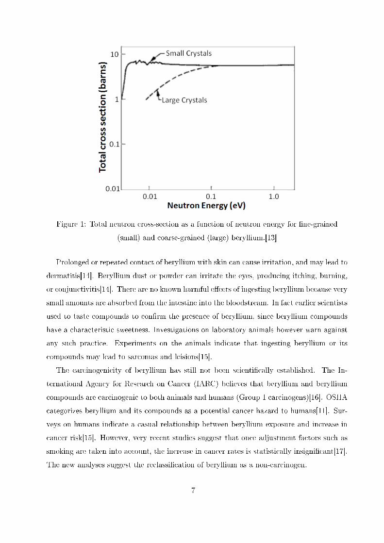
Figure 1: Total neutron cross-section as a function of neutron energy for �ne-grained
(small) and coarse-grained (large) beryllium.[13]
Prolonged or repeated contact of beryllium with skin can cause irritation, and may lead to
dermatitis[14]. Beryllium dust or powder can irritate the eyes, producing itching, burning,
or conjunctivitis[14]. There are no known harmful e�ects of ingesting beryllium because very
small amounts are absorbed from the intestine into the bloodstream. In fact earlier scientists
used to taste compounds to con�rm the presence of beryllium, since beryllium compounds
have a characteristic sweetness. Investigations on laboratory animals however warn against
any such practice. Experiments on the animals indicate that ingesting beryllium or its
compounds may lead to sarcomas and leisions[15].
The carcinogenicity of beryllium has still not been scienti�cally established. The In-
ternational Agency for Research on Cancer (IARC) believes that beryllium and beryllium
compounds are carcinogenic to both animals and humans (Group 1 carcinogens)[16]. OSHA
categorizes beryllium and its compounds as a potential cancer hazard to humans[11]. Sur-
veys on humans indicate a casual relationship between beryllium exposure and increase in
cancer risk[15]. However, very recent studies suggest that once adjustment factors such as
smoking are taken into account, the increase in cancer rates is statistically insigni�cant[17].
The new analyses suggest the reclassi�cation of beryllium as a non-carcinogen.
7

Space Group P63/mmc (Space group number: 194)
a 2.286 Å
c 3.583 Å
Table II: beryllium hcp parameters[20]
Due to beryllium's toxicity, certain safety precautions need to be followed in places where
fabrication or machining of beryllium or its compounds takes place. Beryllium levels in
the workplace need to be monitored to ensure compliance with exposure limits. Eyewash
stations and safety showers should be available. Approved respirators should be provided
for processes that would exceed the exposure limit, and for emergencies. High levels of
fumes may be generated when beryllium metal or its alloys are heated. Such workplaces
should be kept isolated and well ventilated with fresh-air. It is also essential to protect the
environment by purifying the exhaust air before releasing it into the atmosphere. A detailed
description of hazards and safety measures associated with beryllium may be found in the
Materials Safety Data Sheet.
IV. SINGLE-CRYSTAL BERYLLIUM
A. Beryllium Crystal Structure and Properties
1. Structure
Beryllium solid exhibits two di�erent crystal lattice structures. The more general form
of beryllium is hexagonal close-packed (hcp) known as a-beryllium. At 1250ºC however,
beryllium bonds rearrange into a body-centered cubic (bcc) structure. This form is called
b-beryllium and is stable between this transition point and beryllium's melting temperature
of 1287ºC.
Figure 2a on page 9 shows a unit cell in the hcp strucutre. Figure 2b on page 9 shows the
hexagonal symmetry in the unit cell. Due to its hexagonal symmetry, the only important
parameters of the unit cell are the lengths a and c. At room temperature, beryllium has
an axial ratio (c/a) of 1.568, the smallest for any hcp metal. Table II on page 8 gives more
information about the crystal structure of beryllium.
8
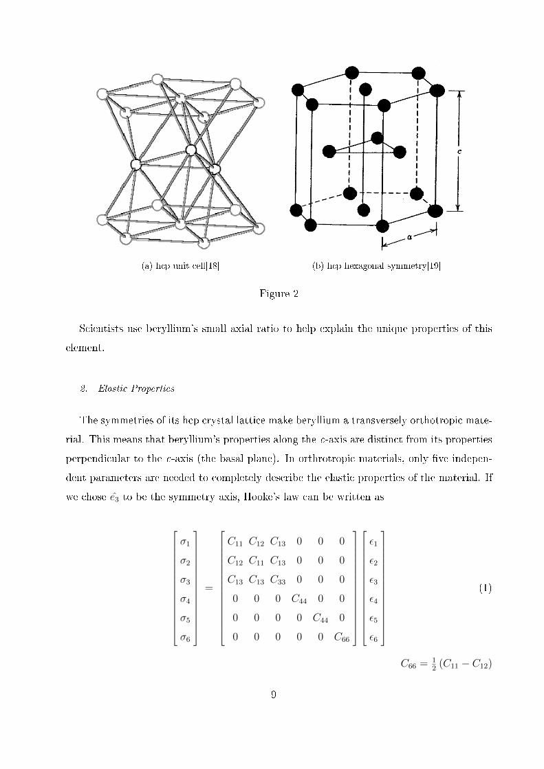
(a) hcp unit cell[18] (b) hcp hexagonal symmetry[19]
Figure 2
Scientists use beryllium's small axial ratio to help explain the unique properties of this
element.
2. Elastic Properties
The symmetries of its hcp crystal lattice make beryllium a transversely orthotropic mate-
rial. This means that beryllium's properties along the c-axis are distinct from its properties
perpendicular to the c-axis (the basal plane). In orthrotropic materials, only �ve indepen-
dent parameters are needed to completely describe the elastic properties of the material. If
we chose e3 to be the symmetry axis, Hooke's law can be written as
σ1
σ2
σ3
σ4
σ5
σ6
=
C11 C12 C13 0 0 0
C12 C11 C13 0 0 0
C13 C13 C33 0 0 0
0 0 0 C44 0 0
0 0 0 0 C44 0
0 0 0 0 0 C66
ε1
ε2
ε3
ε4
ε5
ε6
(1)
C66 =12(C11 − C12)
9

or
[σ] = [C] [ε]
where [C] is the sti�ness tensor.
The inverse relation is expressed as
ε11
ε22
ε33
ε23
ε31
ε12
=
1E11
− ν12E11
− ν31E33
0 0 0
− ν12E11
1E11
− ν31E33
0 0 0
− ν13E11
− ν13E11
1E33
0 0 0
0 0 0 1G23
0 0
0 0 0 0 1G31
0
0 0 0 0 0 1G12
σ11
σ22
σ33
σ23
σ31
σ12
(2)
1G23
= 1G31
= 1C44
1G12
= 1C66
= 2(1+ν12)E11
or
[ε] = [S] [σ]
where [S] is the compliance tensor, and [S] = [C]−1. In both of these tensors, there are
only �ve independent parameters. Scientists generally measure C11, C33, C44, C12 and C13
in experimental investigations.
In the past sixty years, many experiemnts have been conducted to determine these elastic
constants of single-crystal beryllium. Table III on page 11 shows values for Cij from all known
published sources. Voigt-Reuss-Hill (VRH) averaging methods were employed to calculate
quasi-isotropic Young (E ), bulk (B) and shear (G) moduli and Poisson ratio (ν). These four
parameters are helpful in investigating the relationship between monocrystal and polycrystal
beryllium.
The paper by Kadas et al.[29] is a theoretical undertaking to determine the elastic prop-
erties of beryllium from �rst principles. The paper by Migliori et al.[28] is an experimental
investigation to measure the elastic constants of beryllium. We will pay particular atten-
tion to these two papers. Comparing their results from Table III on page 11, we see a
strong agreement between the predicted and measured values of all the constants except for
10

Authors
L.GoldG.TuerSm
ith,
ArbogastFisher,Dever
Silversm
ith,
AverbachTestardi,CondonRow
land
,WhiteMigliori
etal.Kadasetal.
C11
308
282
292.3
294.0
295.4
285.8
288.8
293.6
288.2
C33
357
370
336.4
357.0
356.1
342.8
354.2
356.7
365.2
C44
110
135
162.5
163.0
170.6
166.9
154.9
162.2
156.7
C66
183
131
132.8
133.4
134.8
135.2
134.4
133.4
131.4
C12
-58
2026.7
27.6
25.9
14.8
201.0
26.8
25.4
C13
876.6
14.0
14.2
-1.0
11.0
4.7
14.0
0.0
E293.9
294.4
311.1
315.8
317.6
311.1
306.9
315.2
309.2
B128
111
114.4
117.1
110.4
109.4
109.8
116.8
111.7
G132
139
148.6
150.3
155.6
151.6
148.4
150.1
148.8
ν0.116
0.056
0.047
0.051
0.021
0.026
0.034
0.050
0.039
TableIII:Elasticconstants
ofsingle-crystal
beryllium
atroom
temperature.Allunitsarein
GPaexceptforνwhichis
unit-less.[21�29]
11

E11 E33 ν12 ν13 ν31
290.7 355.5 0.0894 0.0357 0.0437
Table IV: Principal Yonug moduli Eii, and principal Poisson ratios νij of beryllium.[28]
Authors C33/C11 C44/C66
Smith, Arbogast 1.15 1.22
Fisher, Dever 1.21 1.22
Silversmith, Averbach 1.21 1.27
Testardi, Condon 1.20 1.23
Rowland, White 1.23 1.15
Migliori et al. 1.21 1.22
Kadas et al. 1.27 1.19
Averagea 1.21 1.22
aResults from Gold[21] and Tuer[22] were not included in this table due to the signi�cant deviation of their
sti�ness values from later experiments.
Table V: Measure of elastic anisotropy of single-crystal beryllium at room temperature.
C13. Measurements were also made on polycrystal beryllium and excellent agreement was
reported between the measured moduli values and the VRH approximated �gures[28].
For readers of this paper who are not particularly familiar with the sti�ness tensor, a
more intuitive way to decribe the elastic properties of the structure would be to provide
�ve independent elastic constants from among the the Young, bulk and shear moduli and
Poisson ratios. Table IV on page 12 gives Young moduli and Poisson ratios for the principal
directions.
A good way of measuring the degree of elastic anisotropy of hcp metals is by evaluating
the ratios C33/C11 , C44/C66 and C12/C13 . A value of unity for all three indicates perfect
isotropy. We calculated the C33/C11 and C44/C66 ratios for beryllium from published data.
Values for C12/C13 were not calculated due to the high discrepency in the measured values.
The results are given in Table V on page 12. With an average of 1.21 for C33/C11 and 1.22
for C44/C66, beryllium is seen to exhibit some anisotropic behavior.
12

So far, we have only considered the properties of beryllium at room temperature. We
will now outline the e�ect of changing temperature on some of these important properties.
As mentioned earlier, the hexagonal axial ratio (c/a) for beryllium at room temperature
is 1.568. However, this ratio varies with changing temperature. Figure 3a on page 14 shows
this variation as suggested by a theoretical model. Figure 3b on page 14 shows this variation
as measured in an experiment.
Using values from the graph, we estimate that the axial ratio decreases by not more than
0.4% for either of the plots. Since this change is very small, we can assume that the coe�cient
of thermal expansion along the a-axis is essentially equal to the thermal expansion coe�cient
along the c-axis at all temperatures. These results have been experimentally con�rmed as
well[30, 31], as shown in Figure 4 on page 15. In practical terms, this means that beryllium
contracts or expands nearly isotropically with changing temperature.
The sti�ness constants Cij also vary with changing temperature. Figure 5 on page 15
shows their dependence on temperature. The plotted data is from three di�erent published
sources. From the graph, we see that the variation is gradual and the largest change occurs
for C11 and C33 in the given temperature range. There is substantial deviation in the values
from the three sources. Also, accurate data for elevated temperatures is not available.
Further experiments and theoretical investigations are needed in order to more accurately
ascertain the signi�cance of changing temperature on the elastic constants of beryllium.
B. Manufacturing of Single-Crystals
Single crystals are employed in a variety of industrial applications that make use of their
unique properties. For example large silicon monocrystals are used in semiconductor elec-
tronics for their electronic properties, whereas the high strength of single-crystal superalloys
is important in turbine blades[32].
There are a number of ways of manufacturing single-crystals. However, the quality, pu-
rity and defect structure of the single-crystal product will depend on the both the material
and the method used. Listed below are some of the more widely used single-crystal man-
ufacturing techniques, along with a brief description of the apparatus and the processes
involved.
13

(a) Theoretical unit cell axial ratio of α-beryllium as a function of
temperature.[29]
(b) Measured unit cell axial ratio of α-beryllium as a
function of temperature.[30]
Figure 3
14

Figure 4: Measured linear thermal expansion coe�cients as a function of temperature.[30]
Figure 5: Sti�ness constants as a function of temperature. Theoretical results by Kadas et
al.[29] are represented by lines, experimental data of Smith and Arbogast[23] is denoted by
open symbols and measurements of Rowland and White[27] are displayed with �lled
symbols.
15

Figure 6: A simpli�ed diagram of the Verneuil process.
a. Flame Fusion Method Also known as the Verneuil Process, the method was devel-
oped in 1902 by the French chemist Auguste Verneuil. Figure 6 on page 16 shows a simpli�ed
schematic of the Verneuil furnace. Raw materials are fed at the top of the furnace. Hydrogen
and oxygen is supplied into the chamber for combustion. At the tip of the narrow tube where
combustion takes place, a high temperature above the melting poing of the raw materials is
maintained. Liquid droplets of the material are collected at the tip of the support structure
below. The support is slowly pulled away from the combustion region to allow the liquid to
solidify and forms a continuous single-crystal boule. The quality of the crystal depends on
the purity of the initial raw material, the pulling velocity and the temperature distribution
in the combustion region.
The method is primarily used in the fabrication of synthetic gemstones.[33, 34]
b. Czochralski Method The procedure was developed in 1916 by Polish scientist Jan
Czochralski. Figure 7 on page 17 shows a layout of the Czolarski process for production of
doped single-crystal silicon.
In the Czochralski method, the raw material is metled into a crucible, and dopants are
added if required. A seed crystal, mounted on a rod, is introduced into the melt. The
seed crystal's rod is then slowly pulled upwards, allowing solidi�cation of the liquid at the
seed-melt interface. The pulling of the rod may be simultaneously accompanied by rotation
16

Figure 7: The Czochralski process in the case of silicon.
of the rod, rotation of the crucible or both. As the rod is pulled, the crystal grows, and a
cylindrical boule of single-crystal is obtained at the end.
The quality of the crystal depends on the purity of the initial raw materials, the pulling
velocity, the rotation speed and the purity of the crucible and of the atmosphere around the
crystal. It is also important to orient the seed crystal properly, since the lattice orientation
in the �nal boule directly depends on the original orientation of the seed.
This is the most popular method for the production of large single-crystals, and is most
commonly used to manufacture single-crystals of semiconductors and metals.[33, 35]
c. Bridgman-Stockbarger Method In this method, the raw material is sealed inside an
ampoule. The ampoule is then placed in a furnace. Figure 8 on page 18 shows a schematic
of the furnace. Along the length of the furnace, three separate temperature regions are
maintained: the �hot region�, the �temperature gradient region� and the �cold region�. The
solid-liquid interface is located in the temperature gradient region.
Initially, the ampoule is inserted in the furnace such that it resides completely in the hot
region. The raw material melts giving liquid charge. The ampoule is then slowly moved
downward from the high temperature region to the low temperature region, all the while
rotating. As the charge passes through the solid-liquid interface, the melt solidi�es and
starts growing into a single crystal. The interfaces is moved along the complete length of
the ampoule and a single-crystal rod of the material is obtained at the end.
The quality of the crystal depends on the purity of the initial raw material, the pulling
velocity, the rotation speed and the temperature distribution in the furnace. The mechanism
17

Figure 8: A diagram of the Bridgman-Stockbarger process.
may be used in both horizontal and vertical directions. This Brigman-Stockbargter method
also allows the simultaneous growth of multiple single crystals if several ampoules are placed
parallel to each other in the furnace. The method is generally used to manufacture single-
crystals not easily obtained from the Czochralski method, for example gallium arsenide.[33,
36, 37]
d. Float Zone Method The �oat zone method is similar to the Bridgman-Stockbarger
method, but instead of melting the entire raw material, the idea is to move a short uniform
�molten zone� through the material. The technique was originally employed for puri�cation
purposes in a process known as �zone re�ning�, introduced in the early 1950s at Bell Labs.
Figure 9 on page 19 shows the �oat zone mechanism. The feed rod is placed in a feed rod
holder. A small portion of the rod, generally near the bottom, is heated by an RF induction
coil to create the molten zone. The feed rod is then slowly moved downward, and may also
be rotated at the same time. As the rod is lowered, the molten zone moves along the length
of the rod and all the impurities remain within the molten region. Below the molten zone,
the material solidi�es. Because of the lack of impurities in this region, the boule can grow
as a single crystal if a seed crystal is placed at the base. At the end of the process, the
18

Figure 9: Float zone method.
impurities are segregated to one end of the boule, which may be cut o� to give a high purity
single-crystal rod. The process may be repeated several times to further remove impurities
and defects.
One of the main advantages of this crystal growth scheme is the absence of a crucible
or ampoule. This avoids contamination from the crucible, and also ensures that there are
no nucleations zones apart from the site of the seed crystal. The monocrystals produced by
19

the �oat zone are therefore superior in quality than those manufactured from the methods
mentioned earlier.[33, 38�41]
e. Solution Growth Method This method is similar to the Czochralski process. How-
ever, instead of melting the raw material in the crucible, the material is dissolved in an
appropriate solvent until the solution is saturated. Once saturation is achieved, a seed
crystal mounted on a rod is lowered into the solution. For this crystal to grow, the solu-
tion needs to be supersaturated. Supersaturation can be achieved by slow cooling of the
solution, changing the pH of the solution or introducing another solvent that reduces the
solubility of the solute. As the solution is cooled, the solute precipitates and grows on the
seed crystal. The seed crystal's rod is slowly pulled out of the solution allowing the crystal
to grow uniformly. At the end, one large single-crystal may be obtained.
This method is useful for materials with a high melting point. The limitation however lies
in the possible inavailability of appropriate solvents that allow supersaturation and stable
crystallization.[33, 42]
C. Fabrication of Single-Crystal Beryllium
1. Production Processes
At present, there are two primary methods of growing large, high purity single-crystals
of beryllium for use in scienti�c experiments:
a. Slow Directional Solidi�cation of Melt in a Crucible This is one of the earliest and
simplest methods used to grow beryllium monocrystals. Figure 10 on page 22 shows a sketch
of the equipment used for the growth process. A crucible �lled with beryllium feed material
is placed in a vaccuum tight tube. The tube is �lled with high purity argon due to the high
vapor pressure of beryllium. The feed material is completely melted in the furnace, ensuring
that the orientation of grains within the starting material does not in�uence the subsequent
crystal growth. The furnace is slowly raised to allow the directional solidi�cation of the
melt. Solidi�cation �rst begins at the bottom of the crucible. Heterogeneous nucleation
occurs at the crucible wall resulting in the growth of several large single-crystal grains in
the �nal ingot. Figure 11 on page 23 shows the granularity of such an ingot. The single-
crystals may be extracted from the metal ingot by an appropriate cutting instrument, for
20

example with a jeweller's saw or a spark-erosion machine for higher precision. The �rst
beryllium monocrystals were grown using this technique[22]. Monocrystals fabricated by
this method have been mainly used for investigating the mechanical and fracture behavior
of beryllium[21�23, 27, 30, 44, 45] where the perfection of the single-crystals is not vital.
The procedure has proved unsuccessful in growing single-crystals of the quality required for
neutron monochromators[43].
b. Float Zone Method The �oating zone technique has been explained earlier in this
paper on page 18. It has by far been the most popular method of manufacturing beryllium
monocrystals. After its development in 1952, the zone re�ning process was employed to
grow single-crystal beryllium pieces for use in all sorts of experiments[25, 28, 46�51]. Special
precautions are considered while growing beryllium monocrystals by �oat zone. Due to the
high vapor pressure of beryllium, the feed rod is almost always surrounded in a high purity
argon atmosphere. The toxicity of beryllium vapor and dust also necessitates that the entire
apparatues is housed in an airtight glove box.
A popular variant of the �oat zone equipment setup uses a double-ellipsod mirror furnace
instead of the traditional RF induction coil to produce the molten zone in the feed rod. Fig-
ure 12 on page 24 shows a basic schematic of the double-ellipsoid mirror furnace. The lamps
model point sources of radiation surrounded by ellipsoidal mirrors. The radiation re�ects
o� of the mirrors and is concentrated on a particular region of the feed rod, heating it up to
create the molten zone. The equipment is described in detail by Eyer et al.[53]. The double-
ellipsoid mirror furnace avoids vibrations produced by the alternating electromagnetic �eld
in an induction heated facility. Because the furnace also a�ords excellent control of crystal
diameter, the necking process can be implemented to reduce the defect concentration in the
crystal[43, 54]. With these added bene�ts, �oat zone with double-ellipsoid mirror furnace
has been successfully employed to grow beryllium single-crystals with defect concentrations
suitable for use in neutron monochromator applications[43, 54, 55]. These crystals can also
be used as high �ux X-ray monochromators, but further improvement in crystal quality and
increased understanding of the defect structure is needed for use in synchrotron radiation
optics[54].
An experimental investigation has shown that there is no preferred direction for the
growth of beryllium single-crystals[43]. With the use of a properly oriented seed crystal,
it is possible to grow beryllium single-crystals of any desired orientation[43, 56]. In the
21

Figure 10: Sketch of directional solidi�cation equipment and temperature pro�le of the
furnace.[43]
22

Figure 11: Microstructure of a directionally solidi�ed beryllium rod. Numbers 1-9 indicate
the large single-crystal grains.[43]
absence of a seed crystal however, the orientation of the monocrystal will be determined
by the orientation of the pre-existing grains in the feed rod. It is worth noting that in the
past, extruded beryllium stock has often been used as feed in the �oat zone procedure. The
extrusion process results in the grains being oriented in a particular direction within the
rod. Therefore when these rods are used in �oat zone, the resulting single-crystals have a
growth direction almost always parallel to the basal plane[43].
Experiments have also established guidelines about the growth velocity and rotation
velocity of the seed crystal mount, as well as the usefulness of the necking technique. A
growth velocity of 1mm/min is considered ideal[54]. A higher velocity disrupts the single-
23

Figure 12: Schematic of �oating-zone crystal growth in a double-ellipsoid mirror
furnace.[52]
crystal growth, but a lower velocity is not seen to improve the crystal quality. In order to
get a uniform temperature distribution across the molten zone, it is also necessary to rotate
the seed crystal, but no particular dependence on rotational velocity is observed[54]. Lastly,
the necking technique is only deemed useful if the seed crystal contains several grains. The
necking ensures that only one of the grains will propogate and grow into the single-crystal
boule[54]. If the seed crystal is already single-grained, then necking is not required.
Once the single-crystals have been grown by either melt solidi�cation or �oat zone, they
are cut and shaped into a speci�c geometry requied for the experiment. Often the crystals are
worked into a rectangular cross-section with the c-axis parallel to one edge of the rectangle,
with opposite faces ground closely parallel[23, 27]. After obtaining the requierd geometry,
the metal is chemically etched and polished for greater crystal perfection. A metal specimen
may be coated with another material for protection against scratching or surface damage.
2. Production History
Since the early 1950s, samples of beryllium single-crystals have been manufactured for
use in scienti�c experiments. The earliest beryllium monocrystals were obtained by cutting
from large-grained cast ingots grown by melt solidi�cation. With improving technology and
increasing demand for better crystals, the �oat zone process became more widespread and
established itself as the leading beryllium crystal growth mechanism in the 1970s. Instead of
growing their own beryllium monocrystals however, the scienti�c community opted to pur-
24

chase or loan the material from established manufacturers instead. The Franklin Institute[57]
was the largest producer of zone re�ned beryllium single-crystals in the latter half of the
twentieth century. Other manufacturers mentioned in the references include Nuclear Metals,
Inc.[58], The Benjamin Franklin Institute of Technology[59] and Brush Wellman Inc. Elec-
trofusion Products[60]. Information about other national or international manufacturers of
single-crystal beryllium is not currently available.
In the past couple of decades, the semiconductor microprocessor industry has grown
tremendously thanks to the large-scale production and availability of single-crystal silicon
wafers. Unfortunately, this has not been the case with beryllium. High quality beryllium
monocrystals are still generally expensive and di�cult to acquire. A single-crystal beryllium
rod of approximately 15mm diameter and 25mm length will cost approximately $30,000 a
piece[61]. In comparison, a single-crystal silicon piece of the similar dimensions and quality
costs less than $10 a piece[62�64].
The epitaxial growth of single-crystal beryllium �lms was �rst reported in 1992 by a
group of scientists from the University of Arizona, Tucson[65]. Single-crystal �lms were
grown on α-Al2O3(sapphire), silicon and germanium substrates at several di�erent substrate
temperatures and deposition rates, and the various results were published in a series of
papers[65�70] between 1992 and 1994. It was determined that beryllium forms an epitaxial
overlayer with Be(0001) layer parallel to α-Al2O3(0001), Si(111) and Ge(111). In situ and ex
situ analysis on the �lms indicated that all beryllium layers grown were high quality single-
crystals. The crystal perfection was better for Ge than for Si, which in turn was better than
for α-Al2O3[70]. This is attributed to the small lattice mismatches between beryllium and the
substrates. The lattice mismatches for Be (0001) with α-Al2O3(0001), Si(111) and Ge(111)
are 3.9%, 3.4% and 1.0% respectively[70]. A direct relation was also observed between
crystal quality and the substrate temperature at the time of crystal growth. The �lms were
grown with temperatures between 100ºC and 500ºC. The structural coherence length and
therefore the crystal quality was observed to increase with increasing temperature. At the
same time however, formation of discontinuous �islands� instead of a continuous Be �lm was
seen for temperatures beyond 300ºC. In the case of Si(111) and Ge(111), the �lm surface
also became visibly rough at these high temperatures. Such unwanted features degrade
the overall quality of single-crystal �lms. Table VI on page 26 shows the best growth
temperature for each substrate material as determined by x-ray di�raction and ion beam
25

Substrate Growth Temperature (ºC) X-ray Di�raction Rocking Curve FWHM Ion Beam Channeling qmin
α-Al2O3 125 0.51±0.02 0.81±0.02
Si 300 0.24±0.02 0.33±0.02
Ge 300 0.19±0.02 0.18±0.02
Table VI: Summary of best Be �lms grown on each of the three substrates.[70]
channeling parameters. The best �lms were grown on Ge(111) at 300ºC.
V. CONCLUSION
With improved zone re�ning technology and the mirror furnace �oat zone technique, it is
possible to grow beryllium crystals without sub-grains and with a low defect density. With
these high quality crystals now available, it is worthwhile to investigate the application of
monocrystal instead of polycrystal beryllium in x-ray windows. The lack of grain bound-
aries within the single-crystal lattice would a�ord improved x-ray transmission and avoid
unwanted attenuation due to scattering of the x-rays. Also, development of beryllium for
monochromator applications in synchrotron facilities looks promising. Experiments need to
be conducted on available crystals to ascertain their performance in lens and monochroma-
tor applications. Further theoretical and experimental investigations are also required to
understand and in�uence of impurities and defects on the x-ray characteristics of beryllium.
Acknowledgments
I am extremely grateful to Dr. Eric Prebys, Dr. Linda Spentzouris and the Lee Teng
Committee for this wonderful opportunity to explore accelerator physics. I would like to
thank the organizers of US Particle Accelerator School, particularly Dr. William Barletta,
for the amazing arrangements he made to help us learn so much during our short stay at
Boston. My special thanks to my mentor, Dr. Ali Khounsary, for his guidance, support
and advice throughout the internship. I also got valuable support and suggestions from Dr.
Curt Preissner, Dr. Bran Brajuskovic, Dr. Lahsen Assou�d. I also thank Mary Straka,
Cindy Crawford and the Argonne librarians for helping me with the library resources. I
26

thank Loretta Cokeley for the administrative support. I would also like to thank fellow Lee
Teng interns Adam Alongi, Qingyi Wang, Branko Popovic and Kenneth Schlax for their
continuous encouragement and advice. And last but not least, I would like to thank all
the interns at Argonne National Laboratory for making this summer a truly educational
experience.
[1] http://www.berylliumproducts.com/CommercialXray.aspx
[2] http://aps.anl.gov/About/ALD/
[3] J. R. De Laeter, J. K. Bohlke, P. De Bievre, H. Hidaka, H. S. Peiser, K. J. R. Rosman, P. D.
P. Taylor, �Atomic Weights of the Elements: Review 2000 (IUPAC Technical Report)�, Pure
Appl. Chem. 75, 683-800 (2003)
[4] K. A. Walsh, �Extraction�, in D. R. Floyd, J. N. Lowe, Beryllium Science and Technology Vol.
2 (1979), pp. 1
[5] http://en.wikipedia.org/wiki/Beryllium
[6] http://en.wikipedia.org/wiki/Aluminium
[7] http://en.wikipedia.org/wiki/Silicon
[8] http://en.wikipedia.org/wiki/Copper
[9] F. Aldinger, �Flow and Fracture of Single Crystals�, in D. Webster, G. J. London, Beryllium
Science and Technology Vol. 1 (1979), pp. 7,11
[10] R. J. Hanrahan Jr., �Moisture e�ects on the oxidation of beryllides�, in M. McNallan, E. Opila,
T. Maruyama, T. Narita, High Temperature Corrosion and Materials Chemistry (2000), pp.
145-146
[11] Materials Safety Data Sheet
[12] A. Goldberg, �Physical and Nuclear Properties�, in K. A. Walsh, Beryllium Chemistry and
Processing (2009), pp. 42
[13] A. Goldberg, �Physical and Nuclear Properties�, in K. A. Walsh, Beryllium Chemistry and
Processing (2009), pp. 48
[14] http://en.wikipedia.org/wiki/Beryllium_poisoning
[15] R. M. Bruce, L. Ingerman, A. Jarabek, �Toxicological Review of Beryllium and Compounds�,
CAS No.7440-41-7, (1998)
27

[16] http://www.inchem.org/documents/iarc/vol58/mono58-1.html
[17] http://www.brushwellman.com/EHS/FAQ/FAQ%20201.pdf
[18] http://�gwitandfriends.info/Metalle-Tut/hcp.gif
[19] http://www.benbest.com/cryonics/lessons.html
[20] A. Goldberg, �Physical and Nuclear Properties�, in K. A. Walsh, Beryllium Chemistry and
Processing (2009), pp. 27
[21] L. Gold, �Evaluation of the Sti�ness Coe�cients for Beryllium from Ultrasonic Measurements
in Polycrystalline and Single Crystal Specimens�, Phys. Rev. 77, 390-395 (1950)
[22] G. Tuer, unpublished research quoted in D. Lillie, in The Metal Beryllium (ASM, Cleveland,
1955), pp. 304�327
[23] J. F. Smith, C. L. Arbogast, �Elastic Constants of Single Crystal Beryllium�, J. Appl. Phys.
31, 99-102 (1960)
[24] E. Fisher, D. Dever, Argonne National Laboratory Report 7155, 192-197 (1965)
[25] D. J. Silversmith, B. L. Averbach, �Pressure Dependence of the Elastic Constants of Beryllium
and Beryllium-Copper Alloys�, Phys. Rev. B 1, 567-571 (1970)
[26] L. R. Testardi and J. H. Condon, �Landau Quantum Oscillations of the Velocity of Sound in
Be: The Strain Dependence of the Fermi Surface�, Phys. Rev. B 1, 3928-3942 (1970)
[27] W. D. Rowland and J. S. White, �The determination of the elastic constants of beryllium in
the temperature range 25 to 300°C�, J. Phys. F: Met. Phys. 2, 231-236 (1972)
[28] A. Migliori, H. Ledbetter, D. J. Thoma, T. W. Darling, �Beryllium's monocrystal and poly-
crystal elastic constants�, J. Appl. Phys. 95, 2436-2440 (2004)
[29] K. Kadas, L. Vitos, R. Ahuja, B. Johansson, J. Kollar, �Temperature-dependent elastic prop-
erties of α-beryllium from �rst princilpes�, Phys. Rev. B 76, 235109 (2007)
[30] R. W. Meyerho�, J. F. Smith, �Anisotropic Thermal Expansion of Single Crystals of Thallium,
Yttrium, Beryllium, and Zinc at Low Temperatures�, J. Appl. Phys. 33, 219-224 (1962)
[31] A. Goldberg, �Physical and Nuclear Properties�, in K. A. Walsh, Beryllium Chemistry and
Processing (2009), pp. 36
[32] http://www.appropedia.org/Single_Crystal_Turbine_Blades
[33] Z. Liu, A. Stavrinadis, �Growth of Bulk Single Crystal and its Application to SiC�,
http://www.mansic.eu/documents/PAM1/Chaussende.pdf (2008)
[34] http://en.wikipedia.org/wiki/Verneuil_process
28

[35] http://en.wikipedia.org/wiki/Czochralski_process
[36] http://www.fkf.mpg.de/crystal/D6-Bridgman_growth.pdf
[37] http://en.wikipedia.org/wiki/Bridgman-Stockbarger_technique
[38] http://www.tf.uni-kiel.de/matwis/amat/elmat_en/kap_6/advanced/t6_1_3.html
[39] http://en.wikipedia.org/wiki/Zone_melting
[40] W. G. Pfann, J. Met. 4, Trans. AIME 194, 747 (1952)
[41] http://seam.ustb.edu.cn/UploadFile//20071228063558406.pdf
[42] http://en.wikipedia.org/wiki/Crystallization
[43] S. Jönsson, �The Crystallization Behaviour of Beryllium�, J. Crystal Growth 63, 116-124 (1983)
[44] I. I. Papirov, G. F. Tikhinskii, S. S. Avotin, P. I. Stoev, �Study of failure of beryllium crystals
on the basal plane�, Strength of Materials 8, 1192-1197 (1976)
[45] I. I. Papirov, P. I. Stoev, G. F. Tikhinskii, �Failure of single crystals of beryllium�, Strength of
Materials 11, 763-769 (1979)
[46] J. F. Breedis, A. Lawley, J. A. Zeiger, �Fatigue Studies of Single Crystal Beryllium�, Report
NASA-CR-59031, Contract No. NASR-145, (1964)
[47] A. Lawley, J. F. Breedis,J. D. Meakin, �The Microstrain Behavior of Beryllium Single Crystals�,
Acta Metallurgica 14, 1339-1347 (1966)
[48] D. H. Buckley �E�ect of orientation of friction characteristics of single-crystal beryllium in
vacuum (10-10 Torr)�, Report NASA-TN-D-3485, (1966)
[49] R. K. Govila, M. H. Kamdar, �Cleavage in beryllium monocrystals�, Metallurgical and Mate-
rials Transactions B 1, 1011-1018 (1970)
[50] L. E. Pope, J. N. Johnson, �Shock-wave compression of single-crystal beryllium�, J. Appl. Phys.
46, 720-729 (1975)
[51] M. Wilhelm, F. Aldinger, �Low temperature basal cleavage in single crystals of beryllium and
beryllium alloys with copper�, Z. Metallk. 66, 323-329 (1975)
[52] C.W. Lan, �Three-dimensional simulation of �oating-zone crystal growth of oxide crystals�, J.
Crystal Growth 247, 597-612 (2003)
[53] A. Eyer, R. Nitsche, H. Zimmermann, �A double-ellipsoid mirror furnace for zone crystallization
experiments in spacelab�, J. Crystal Growth 47, 219-229 (1979)
[54] S. Stiltz, A. K. Freund, �Growth of High Quality Beryllium Crystals for Neutron Monochro-
mators�, J. Crystal Growth 88, 321-331 (1988)
29

[55] A. K. Freund, S. Jönsson, S. Stiltz, G. Petzow, �The development of beryllium single crystals
for neutron monochromatization�, Journal of Nuclear Materials 124, 215-221 (1984)
[56] J. Deloche, Y. Malmejac, B. Schaub, �Etude des conditions de croissance de monocristaux de
beryllium�, J. Crystal Growth 13-14 , 814-817 (1972)
[57] The Franklin Institute | 222 North 20th Street, Philadelphia, PA 19103
[58] The Nuclear Metals, Inc. (NMI) | 2229 Main Street, Concord, MA, 01742
[59] The Benjamin Franklin Institute of Technology | 41 Berkeley Street, Boston, MA 02116
[60] Brush Wellman Inc. Electrofusion Products | 44036 South Grimmer Boulevard, Fremont, CA
94538
[61] Merry Boo, Sales/Technical Support Engineer, Brush Wellman Inc. Electrofusion Products,
BW-Electrofusion Quote Reference No. 3007107 (2010)
[62] http://cgi.ebay.com/SILICON-Pulled-Single-Crystal-Metal-BLANKS-1-5-OD-/230415438215
[63] http://cgi.ebay.com/SILICON-Pulled-Single-Crystal-rect-plate-100630-48-/230494507711
[64] http://cgi.ebay.com/SILICON-Pulled-Single-Crystal-rect-plate-100630-49-/380247707628
[65] J. A. Ru�ner, J. M. Slaughter, C. M. Falco, �Epitaxial growth of Be on α-Al2O3�, Appl. Phys.
Lett. 60, 2995-2997 (1992)
[66] J. A. Ru�ner, J. M. Slaughter, J. Eickmann, C. M. Falco, �Epitaxial growth and surface
structure of (0001) Be on (111) Si�, Appl. Phys. Lett. 64, 31-33 (1994)
[67] Charles M. Falco, �Laboratory for X-Ray Optics, Final Technical Report�, Contract No.
AFOSR-90-0140 (1993)
[68] Charles M. Falco, Jon M. Slaughter, �Laboratory for X-Ray Optics, Final Technical Report�,
Contract No. F49620-93-0201 (1994)
[69] J. A. Ru�ner, J. M. Slaughter, P. A. Kearney, C. M. Falco �Fabrication and characterization
of beryllium-based multilayer mirrors for soft x-rays�, SPIE Vol. 1547, 176-186 (1992)
[70] C. M. Falco, J. Eickmann, J. A. Ru�ner, J. M. Slaughter, �Growth and surface structure of
epitaxial Be thin �lms�, SPIE Vol. 2364, 338-344 (1994)
30